

Page 1
TECHNICAL
GUIDE
IP Network Guidance:
HelixNet Digital Partyline
Page 2
Introduction
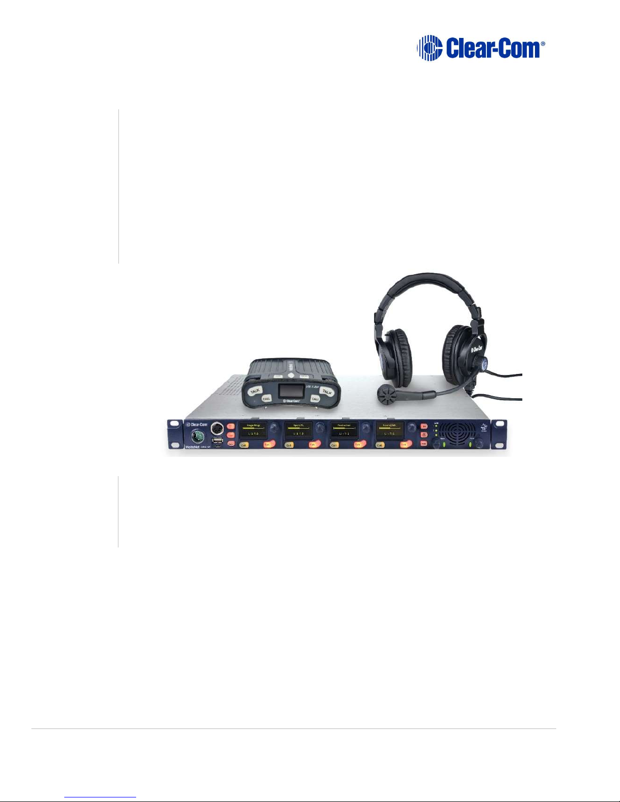
HelixNet Digital Partyline
The HelixNet Digital Partyline system offers a tremendous amount of flexibility and
performance to broadcast and live productions requiring partyline/group
communications. HelixNet Digital Network Partyline System delivers all the features and
functions of industry-standard analog partyline systems along with digital audio clarity
over 24 channels and IP connectivity via Powerline or connected Power-over-Ethernet
(PoE). HelixNet operates over any standard single, twisted-pair, shielded cable (like
microphone cable) using our Powerline technology. As this paper will explain, it can also
be interconnected over standard IT network infrastructures via IP/LAN or IP connected
Powerline.
HelixNet
Network
Guidance
This guide provides specifications, best practices and guidance for the integration of
HelixNet into an existing or new IP network. Several of the terms used in this paper are
technical in nature, please see the glossary at the end of the document for explanations
and definitions.
Technical Guide | HelixNet IP Network Guidance Page 2
Page 3
HelixNet
“Network”
Digital
Partyline
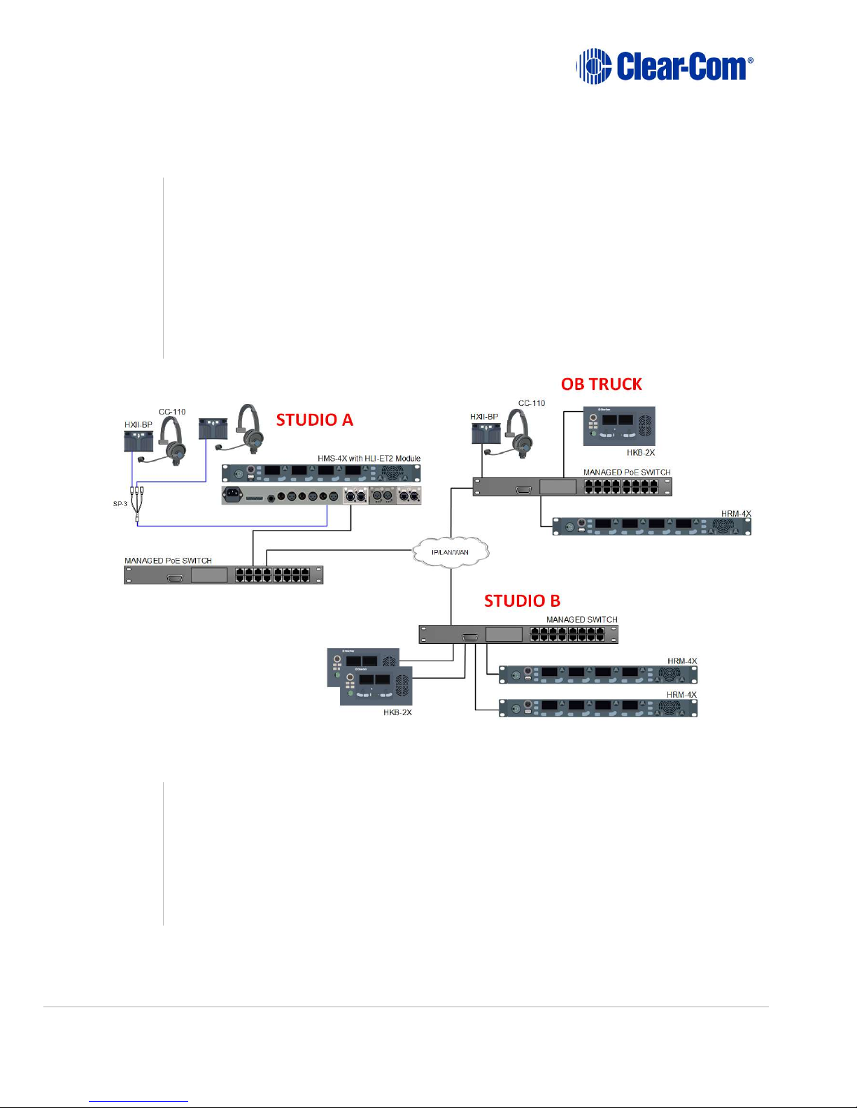
In Figure 1 (below) teams in separate studios (A and B) can communicate with an
outside broadcasting truck on the same digital partyline system over their existing IP
network. With cabling integration possibilities in either XLR or CAT5/6, HelixNet
becomes a flexible solution in multiple scenarios.
- Live Production
- Performing Arts and Theatre
- House of Worship
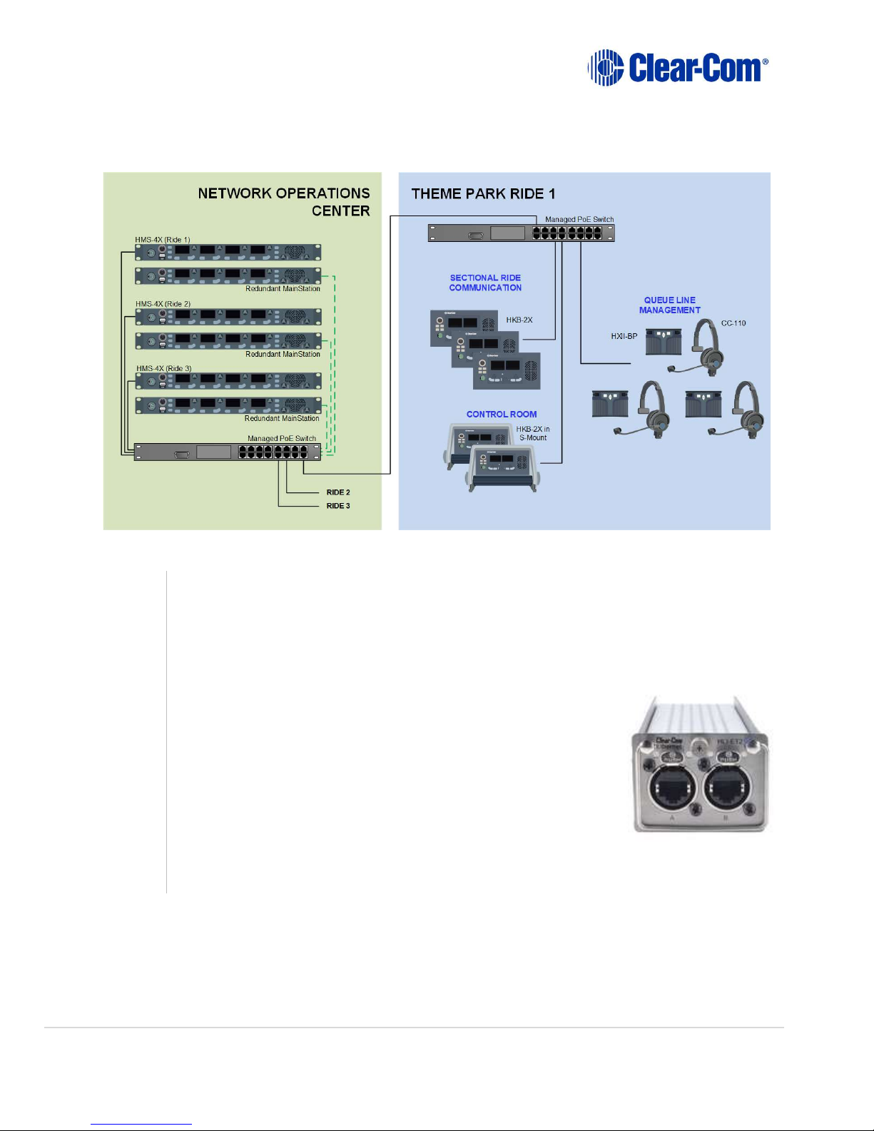
- Theme Park Ride Communications (Figure 2)
Because of its IP capability, HelixNet is an excellent solution for intercom
communication for Theme Park Rides as shown in Figure 2 (below). A Park’s Network
Operations Center houses sets of HelixNet Main Stations per ride – one HMS is live
production, the second is a redundant back up. The HMS connects to a local switch, the
local switch then connects via CAT5/6 to a second PoE switch at the ride locale. HelixNet
endpoints (HKB and HXII-BP) are placed at strategic positions within the ride to connect
operators and provide a safe experience for the customer.
Technical Guide | HelixNet IP Network Guidance Page 3
Figure 1
Page 4
HLI-ET2
Network
Topology
The HelixNet Main Station (HMS-4X), Remote Station (HRM-4X), Speaker Station (HKB2X) and Beltpack (HXII-BP) use a 100Mb Network Interface Card (NIC). Devices are
physically added to the network by connecting the RJ45 LAN port on the device to an
Ethernet switch port using a shielded CAT5 or CAT6 cable. HRM, HKB and HXII-BP units
can be powered using PoE Ethernet switches or a local power supply. To connect the
HMS-4X to the Ethernet switch, it must be fitted with a HLI-ET2
2-port Ethernet module (pictured). There are two ports
available on each module. The HLI-ET2 ports act as two normal
switch ports. They can be daisy chained together, but they do
not use Spanning Tree Protocol - connecting both ports to the
same switch can cause redundant paths or loops which will
cause a packet storm and severely degrade both networks.
Best practice would be to use one port to connect to the
network switch, and the second port to daisy chain to other
HelixNet or LQ devices.
Figure 2
Module
Technical Guide | HelixNet IP Network Guidance Page 4
Page 5
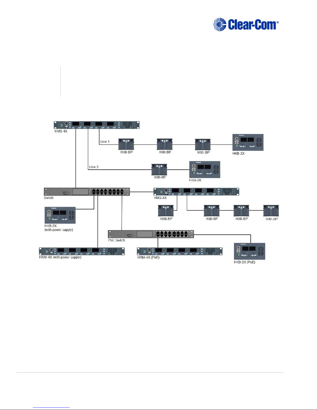
HelixNet devices can be paired/linked together across subnets. They use the mDNS
protocol to auto-discover each other. Figure 3 below shows a typical network topology
with HelixNet endpoints connected directly to the HMS-4X mainstation, endpoints with
a local power supply connected via a switch, and endpoints connected via a PoE switch.
Technical Guide | HelixNet IP Network Guidance Page 5
Figure 3
Page 6

HMS Network Configuration:
Network
Configuration
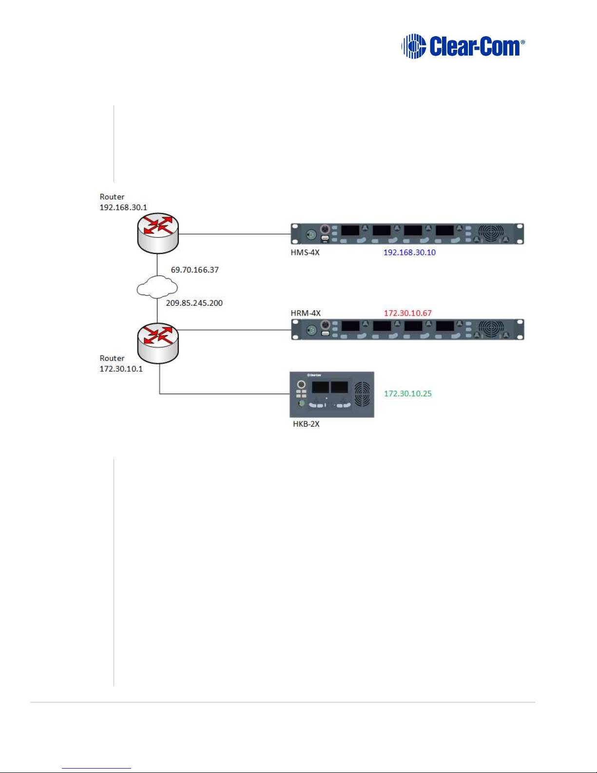
Connecting Across Routable Subnets
Company networks typically have multiple subnets or VLANs. IP routers are already configured
to route IP traffic across those subnets. The HMS and HRM/HKB/HXII-BP must have their IP
address, Subnet mask and Gateway set properly (all automatically done when there is a DHCP
server available on the network). If the HRM/HKB/HXII-BP is deployed on a different subnet,
you will need to Pair to Station by entering the IP address of the HMS (Pair to Station by Name
is not available in the Figure 4 example below). “Pair to Station by Name” is discussed later in
this document.
Figure 4
IP Address: 192.168.30.10
Subnet Mask: 255.255.255.0
Gateway: 192.168.30.1
HRM Network Configuration:
IP Address: 172.30.10.67
Subnet Mask: 255.255.0.0
Gateway: 172.30.10.1
Pair to Station:192.168.30.10
HKB Network Configuration:
IP Address: 172.30.10.25
Subnet Mask: 255.255.0.0
Gateway: 172.30.10.1
Pair to Station:192.168.30.10
Technical Guide | HelixNet IP Network Guidance Page 6
Page 7
Connecting Across Non
-
Routable Subnets
HMS Network Configuration:
The second scenario occurs when an HMS is in a private/separate network, not directly
reachable from where the HRM/HKB is located. A reachable IP router/gateway, on the network
where the HMS is located, must be configured to forward all the IP traffic for port 6001 TCP/UDP
to the HMS (Figure 5):
Figure 5
IP Address: 192.168.30.10
Subnet Mask: 255.255.255.0
Gateway: 192.168.30.1
Here the Router on the HMS side must port-forward everything from 6001 TCP/UDP to
192.168.30.10:6001
HRM Network Configuration:
IP Address: 172.30.10.67
Subnet Mask: 255.255.0.0
Gateway: 172.30.10.1
Pair to Station: 69.70.166.37
HKB Network Configuration:
IP Address: 172.30.10.25
Subnet Mask: 255.255.0.0
Gateway: 172.30.10.1
Pair to Station: 69.70.166.37
Technical Guide | HelixNet IP Network Guidance Page 7
Page 8

Firewall:
TCP/UDP
IP Ports
It should be noted that HelixNet reserves the 10.0.0.0/16 network for connecting
HelixNet devices by powerline – placing HelixNet devices/systems on 10.x network may
cause issues.
To support remote connectivity of HelixNet endpoints external to a LAN or WAN, port
forwarding rules will be needed to achieve the required connectivity to the HMS that
has been set into Link-Master mode. Listed below is the Port # and a description of what
the opened port provides access to.
- Port 6001 TCP - Pairing with HKB-2X, HRM-4X, HXII-BP, Authenticate, update,
and reboot
- Port 6001 UDP - Audio
- Port 80 HTML – Core Configuration Manager (not recommended as
management of the system should be limited to a device within the secured
network)
LinkMaster
Mode
To create a Link-Group, you must designate one unit as Link-Master in the Core
Configuration Manager (CCM). The Core Configuration Manager (CCM) interface
provides an intuitive software utility for HelixNet on any browser-enabled platform. The
CCM facilitates a quick and simple means of configuring any devices in a Link-Group,
including role-based configuration of endpoints, save and restore, and live monitoring
of all system components.
The Link-Master designation serves three main purposes:
- It facilitates Link-Group membership.
- It is the owner of configured Role information, meaning that Roles will only
persist (be maintained consistently) if the Link-Master is operational.
- It is responsible for the synchronization and distribution of both configuration
(Roles) and device availability status throughout the Link-Group.
Note: Clear-Com recommends that the IP address of the Link-Master is allocated
statically. When allocated by DHCP, the IP address can change. If this happens the LinkMembers will no longer be able to reach the Link-Master device, and Role information
may not be available.
Note: Any device can be set to Link-Master or Link-Member. The default setting for
HelixNet linking mode is Link Disabled.
HelixNet devices that are not identified as master will have the designation of LinkMember. Joining a device to a Link-Group requires that device to be set to Link-Member
which will prompt the user to enter the IP address of the Link-Master. Once joined to
the Link-Group, all devices attempt to connect to all other devices within the group.
Technical Guide | HelixNet IP Network Guidance Page 8
Page 9

When connecting HelixNet to a
managed network switch, ensure that the connection performs
- Configuration and control of any device is possible through any other unit in the
group
- Configuration information is both distributed and persisted within every node of
the group
- The Link-Group significantly reduces loss of service within the set group
HelixNet
Pairing by
Name
HKB-2X, HRM-4X, and HXII-BP on the same subnet can pair to a system by name. The
system uses mDNS to propagate HMS and HRM (when configured as an expansion host)
presence in a network. As a device populates it’s mDNS entry, it specifies an ID, an IP
address, a name and a list of services.
When configuration changes, the mDNS entry is updated and all devices connected “by
name” will update and re-pair/link/expand as required.
NETWORK INSTALLATION
Managed
Ethernet
Switch
at a minimum of 100Mb full duplex.
If the system is using more than one switch, ensure that the bridge between the switches also
operates at a minimum of 1Gb full duplex. When using a managed switch, the port connected
to the HelixNet Main Station and endpoints should be set at 100Mb versus letting the port autonegotiate.
Note: You do not need to set all ports to 100Mb, only the ones connected to the HMS-4X, HRM4X, HKB-2X & HXII-BP.
We recommend the following specifications when selecting a managed switch to use with
HelixNet:
- 100/1000Base-T Layer 3 Managed Switch
- QoS support with the audio traffic prioritized over other data
- If Energy Efficient Ethernet is supported, ensure it is disabled
- SPF/Mini-GBIC support
If connecting two or more switches together, we recommend the bridge / link
ports between the switches supports at least 1GB.
Technical Guide | HelixNet IP Network Guidance Page 9
Page 10

Unmanaged
Ethernet
Switch
Hubs
Connecting
HelixNet to
Your
Network
Since unmanaged Ethernet switches do not allow user manage port speeds, it is best to
use a 100Mb switch. An unmanaged Ethernet switch can connect to a managed switch,
but the port that is physically connected to the HelixNet device or endpoint must be
100Mb full duplex.
Hubs should not be used with HelixNet. A Hub’s all port transmission will crash the
HelixNet Network.
Integrating HelixNet into your network may need an IP addressing scheme defined with
the help of your IT department. We recommend using a STATIC IP address for the
HelixNet Main Station then leaving all other HelixNet devices on DHCP. However, there
are a few scenarios where DHCP may not be desirable.
- In a large HelixNet systems with roughly 30 HRMs, 10 HKBs and 10 beltpacks, a
DHCP server may not assign addresses to devices fast enough for a network this
size. In this case, it is better to utilize static IPs for each device.
- When a port on a Cisco switch starts up, there is a Spanning Tree Protocol (STP)
exchange before IP traffic starts flowing properly. This exchange can take up to
a minute to complete. In this situation HelixNet devices configured for DHCP
addressing will often timeout before receiving its initial IP address. They will
retry and get a proper IP address a minute later, but our recommendation in this
case is to either use static IP addresses or enabling PortFast on Cisco switches
port.
If no DHCP server is found, the Main Station and all other HelixNet devices will revert to
an unused link-local address in the 169.254.0.0/16 block - devices on this subnet block
will then be discovered by the Main Station. If neither of these options are used, the
Networking menu on the device allows you to disable DHCP and set static IP addresses.
Technical Guide | HelixNet IP Network Guidance Page 10
Page 11

Disable
IMGP
Snooping
IGMP snooping is a tool used to make network traffic more efficient. A switch with IGMP
snooping enabled will typically only send data to nodes that have an existing
relationship with the sender. Because IGMP snooping is covered by two overlapping
standards, one from IEEE and one from IETF, implementation can vary depending on
the manufacturer.
When connecting HelixNet equipment together, IGMP snooping should be disabled.
With HelixNet, especially during discovery/linking, data needs to flow throughout the
network so all HelixNet equipment (endpoints and devices) capture data they need.
Additionally, if you experience a problem where HelixNet station names are
disappearing from linking/pairing/expansion menus, it could be caused by the snooping
feature. IGMP reportedly can also cause issues with Bonjour/mDNS and PTP.
Example: NetGear / Extreme switches have IGMP enabled by default. Ensure that
""block unregistered multicast"" is set to off. This is a scenario where IGMP snooping
blocks traffic that must be allowed for mDNS and PTP.
Technical Guide | HelixNet IP Network Guidance Page 11
Page 12

HelixNet
Audio
Bandwidth
Bandwidth required is based around the Audio stream – there is additional data on the
network, but it is not significant. Audio runs at 300kbps per audio stream. Figure 6
(below) shows a typical HelixNet system with four endpoints (HelixNet Devices)
connecting to the Main Station over powerline, and three endpoints (HelixNet Devices)
connecting to a switch, which in turn connects to the same Main Station.
Figure 6
- Each HelixNet device transmits at 300 kbps when a user is talking.
- The HMS-4X only routes audio where appropriate, between an audio source and
a listening destination. Audio mixing is done at each destination.
- An audio source is sent once to the HMS-4X. The HMS-4X then sends the audio
stream point-to-point to each destination that is currently listening to that
source.
- Talk pressed/latched = 300kbps is sent to HMS-4X.
- Each 2W/4W/PGM port when assigned = 300kbps is sent internally to HMS-4X.
- PGM on an HRM if assigned = 300kbps for the mic, 300kbps for PGM/SA
- No Talk or No Assignment = no audio is sent to HMS-4X.
Note: Enabling VOX on 2-wire or 4-wire port will significantly reduce the bandwidth as
otherwise, audio will always be sent from the I/O source to any listener in the system.
The same occurs for the distribution of the Program.
- Audio and Data sent will max out at 1.2Mbps per destination.
- Between linked HMS-4X stations, each audio source is sent once, and only if a
user is listening on the second HMS-4X.
Technical Guide | HelixNet IP Network Guidance Page 12
Page 13

Based on the bandwidth allocations noted, the HelixNet system in Figure 7 (below) will
carry the talker’s 300kbps to the HMS-4X. One listener is on the Main Station, and the
three end points receive 900kbps combined.
One User Talking / Four Users Listening
Figure 7
Technical Guide | HelixNet IP Network Guidance Page 13
Page 14

Figure 8 increases the number of talkers to two, on the same channel, with the same
four endpoints listening.
Two Users Talking on Same Channel / Four Users Listening
Examples
Figure 8
Workflow (worst-case scenarios where most or all talk keys are latched):
Theater: 1 HMS-4X, 20 HXII-BP, 8-10 channels. 1 Production channel, HXII-BP evenly
distributed on other channels (3-4 persons per channel), all over IP (connected to a
single 24 port switch)
Rehearsal: All Talk latched, many people listening to 2-3 persons talking at the same
time.
Bandwidth usage:
- 300kbps from each HXII-BP to switch
- 600-900kbps from switch to each HXII-BP
- 20*300kbps = 6Mbps from switch to HMS-4X
- 20*(600-900) = 12-18Mbps from HMS-4X to switch
Larger Theater: 3 linked HMS-4X, 39 HXII-BP evenly distributed over the 3 HMS-4X, 15
channels.
Rehearsal: All Talk latched, many people listening to 2-3 persons talking at the same
time.
Bandwidth usage:
- 300kbps from each HXII-BP to switch
Technical Guide | HelixNet IP Network Guidance Page 14
Page 15

- 600-900kbps from switch to each HXII-BP
- From switch to each HMS-4X
o 13*300kbps = 3.9Mbps from switch to HMS-4X (for HXII-BP)
o 2*13*300kbps = 7.8Mbps from switch to HMS-4X (for receiving 13
audio sources from each other two HMS-4X)
o Total = 11.7Mbps
- From switch to each HMS-4X to switch
o 13*(600-900) = 7.8-11.7Mbps from HMS-4X to switch (for HXII-BP)
o 2*13*300 kbps = 7.8Mbps from HMS-4X to switch (for sending 13
audio sources over to other two HMS-4X)
o Total = 15.6 – 19.5Mbps
Up to 60 HelixNet devices / endpoints can be connected over a network, making it
important to understand and calculate the bandwidth needs for the HelixNet system.
Endpoints are assigned to devices as follows:
- One (1) endpoint for HXII-BP/HKB-2X
- Two (2) endpoints for HMS (Mic/Headset/Loudspeaker is one, PGM is the
other)
- One (1) endpoint per 2-wire/4-wire port (i.e. 2 endpoints per HelixNet
module or LQ)
- Two (2) endpoints for each module installed – HLI-2W2, HLI-4W2
- Three (3) endpoints for HRM (Mic/Headset/Loudspeaker is one, 4-wire PGM
input is the second, 4-wire SA Out is the third)
Utilizing more than 60 endpoints may result in choppy audio. On IP connected
endpoints, you will see the blinking “Paired” icon as audio packets are lost. On
powerline, the bandwidth available is shared between equipment on that line and is
reduced the further you are from the HMS-4X. The number of bars of the powerline
icon indicates how much bandwidth you have. At two bars, or less, you will begin to
experience choppy audio.
Clear-Com has developed a powerline calculator to not only manage bandwidth, but to
also assist you in cable length and power limits. The calculator can be found here:
http://www.clearcom.com/userfiles/file/Software/HelixNetCablingCalculator/index.html#/
Technical Guide | HelixNet IP Network Guidance Page 15
Page 16

We have designed all HelixNet devices to comply with the IEEE 802.3af
-
2003 PoE standard which
In general, depending on the number of devices on a network, users will experience
some latency. The table below describes what you can expect over powerline or IP.
Specification Value
Latency on Powerline 30-80ms (Depends on cable type and length, and
how many devices are connected. The greater
the number of devices, the greater the latency.)
Latency over IP Network
Bandwidth Used 300kbps per active Talker
IP Version IPv4
PoE
Specification
75-80ms Beltpack-to-Beltpack (Powerline)
30-35ms Beltpack-to-Beltpack (Ethernet)
40-60ms Beltpack-to-4Wire (Powerline)
30-35ms Beltpack-to-4Wire (Ethernet)
30-35ms HMS-to-HMS (linked transport of audio)
states up to 15.4 W of DC power on each port. These devices require no more than 12.95W to
operate. (15.4W delivered from the power source with some allowance for loss in the cable).
Ensure the total wattage on the PoE switch can deliver to the total number of PoE devices
connected. Most PoE switches SHARE the total wattage across all ports.
The following devices can be powered by PoE:
- HelixNet Remote station (HRM-4X)
- HelixNet Speaker station (HKB-2X)
- HelixNet II Beltpack (HXII-BP) - the HXII-BP
only uses 4W of PoE power
This IEEE 802.3af standard RJ45 PoE pinout chart
shows what pins carry power for the BP.
Technical Guide | HelixNet IP Network Guidance Page 16
Page 17

SUPPORT
Try our Clear
-
Com Solution Finder knowledgebase of FAQs, resolutions to problems, and "How
Technical
Questions
Technical,
Service and
Repair
Issues
Technical
Training
do I...?" Information was provided by expert Clear-Com product and technical teams and
customers like you. Solution finder is located here: http://www.clearcom.com/support/clearcom-solution-finder
Find your regional Support Contact here: http://www.clearcom.com/contact/support-contacts
Or submit a question online, and a member of the Technical Support staff will respond within
24 hours:
http://www.clearcom.com/support/support-request
Clear-Com offers a wide range of training classes on communication technologies and productspecific operations. Training can be delivered at Clear-Com College (Alameda, CA - USA), ClearCom Academy (Cambridge, UK), Clear-Com Think Academy (Poway, CA - USA), or customized
for delivery at your site with your equipment. Some classes may qualify for CTS© RU credits.
For more information on topics,
GLOSSARY
HelixNet
Terms
Core Configuration Manager (CCM)
The Core Configuration Manager (CCM) interface provides an intuitive software utility
for HelixNet on any browser-enabled platform. The CCM facilitates a quick and simple
means of configuring any devices in a Link-Group, including role-based configuration of
endpoints, account management (Agent-IC, SIP and IVC-32-HX cards), save and restore,
and live monitoring of all system components.
Endpoint
A point in the system where audio data can be delivered and consumed, versus a
“device” which has the capability to route audio to an endpoint.
HMS-4X
The HMS-4X is a 1RU digital partyline main station that provides power and up to 12
networked channels of audio. A single Main Station can support up to 20 digital
beltpacks on a single shielded twisted-pair cable.
Technical Guide | HelixNet IP Network Guidance Page 17
Page 18

HRM-4X
The HRM-4X is a 4-channel 1RU digital partyline headset and speaker Remote Station
that connects to HelixNet HMS-4X Main Stations and other HelixNet user stations over
a single shielded twisted-pair cable. The HRM-4X can be locally powered via an external
power supply or third-party Power-over-Ethernet (PoE) power source.
HKB-2X
The HKB-2X is a 4-channel, two-display with shift page, flush mount digital partyline
headset and Speaker Station that connects to HelixNet Main or Remote Stations over a
single shielded twisted-pair cable. The HKB-2X can be locally powered via an external
power supply or third-party Power-over-Ethernet (PoE) power source.
HXII-BP
The HXII-BP is a rugged and ergonomically designed 2-channel digital partyline beltpack.
A beltpack can have access to two of any twenty-four available system channels over a
single shielded twisted-pair cable or Power-over-Ethernet (PoE).
HLI-ET2
The HLI-ET2 is an Ethernet LAN network interface module for the HMS-4X main station
that enables a dual LAN interface to link to other HMS-4X main stations, connect to
HRM-4X remote stations or HKB-2X speaker stations, and LQ Series devices.
Internet /
Network
Terms
Bandwidth
Bandwidth is also defined as the amount of data that can be transmitted in a fixed
amount of time. For digital devices, the bandwidth is usually expressed in bits per
second(bps) or bytes per second. For analog devices, the bandwidth is expressed in
cycles per second, or Hertz (Hz).
DHCP
DHCP is controlled by a DHCP server that dynamically distributes network configuration
parameters, such as IP addresses, for interfaces and services
Gateway
A default gateway in computer networking is the node that is assumed to know how to
forward packets on to other networks
Technical Guide | HelixNet IP Network Guidance Page 18
Page 19

Hub
Hubs are commonly used to connect segments of a LAN. A hub contains multiple ports.
When a packet arrives at one port, it is copied to the other ports so that all segments of
the LAN can see all packets.
Managed / Unmanaged Switch
A managed switch can be configured to prioritize LAN traffic so the most important
information gets through. An unmanaged switch on the other hand behaves like a “plug
and play” device. It cannot be configured and simply allows the devices to communicate
with one another.
mDNS
multicast Domain Name System (mDNS) resolves host names to IP addresses within
small networks that do not include a local name server.
Powerline
A communication method that uses electrical wiring to simultaneously carry both data
and electric power.
Power over Ethernet (PoE)
Any of several standard or ad-hoc systems which pass electric power along with data on
twisted pair Ethernet cabling. This allows a single cable to provide both data connection
and electric power to devices such as wireless access points, IP cameras, and VoIP
phones.
Quality of Service (QoS)
QoS is a feature of routers and switches which prioritizes traffic so that more important
traffic can pass first. The result is a performance improvement for critical network
traffic. QoS equipment is useful with VoIP phones or in LANs with high volumes of local
traffic.
Router
A router is a device that joins networks together and routes traffic between them. A
router will have at least two network cards (NICs), one physically connected to one
network and the other physically connected to another network.
Spanning Tree Protocol (STP)
A network protocol that builds a logical loop-free topology for Ethernet networks. The
basic function of STP is to prevent bridge loops and the broadcast radiation that results
from them.
Technical Guide | HelixNet IP Network Guidance Page 19
Page 20

Static IP
A static IP address is an IP address that was manually configured for a device, versus
one that was assigned via a DHCP server. It's called static because it doesn't change.
Subnet
A subnetwork or subnet is a logical subdivision of an IP network. The practice of dividing
a network into two or more networks is called subnetting.
TCP
TCP (Transmission Control Protocol) is a standard that defines how to establish and
maintain a network conversation via which application programs can exchange data.
TCP works with the Internet Protocol (IP), which defines how computers send packets
of data to each other
UDP
(User Datagram Protocol) is an alternative communications protocol to Transmission
Control Protocol (TCP) used primarily for establishing low-latency and loss tolerating
connections between applications on the Internet.
Technical Guide | HelixNet IP Network Guidance Page 20
Page 21

About
Clear-Com
Clear-Com
Offices
Clear-Com, an HME company, is a trusted global provider of professional realtime communications solutions and services since 1968. We innovate market
proven technologies that link people together through wired and wireless
systems.
Clear-Com was first to market portable wired and wireless intercom systems
for live performances. Since then, our history of technological advancements
and innovations has delivered significant improvements to the way people
collaborate in professional settings where real-time communication matters.
For the markets we serve -- broadcast, live performance, live events, sports,
military, aerospace and government -- our communication products have
consistently met the demands for high quality audio, reliability, scalability and
low latency, while addressing communication requirements of varying size and
complexity. Our reputation in the industry is not only based on our product
achievements, but also on our consistent level of customer engagement and
dedication to delivering the right solutions for specialized applications, with the
expertise to make it work. Around the globe and across markets, Clear-Com’s
innovations and solutions have received numerous awards and recognitions for
ingenuity and impact to customers.
Americas and Asia-Pacific Headquarters
Clear-Com, LLC
1301 Marina Village Parkway, Suite 105
Alameda, California 94501
United States
Tel: +1.510.337.6600 or 1.800.462.HELP
(4357)
Fax: +1.510.337.6699
Email: SalesSupportUS@clearcom.com
Canada Office
Clear-Com Research Inc.
1430 Hocquart, Suite 101
St-Bruno-de-Montarville
Quebec J3V 6E1
Canada
Tel: +1 (450) 653-9669
Europe, Middle East, and Africa
Headquarters
HME Clear-Com, LTD
2000 Beach Drive
Cambridge Research Park
Cambridge CB25 9TP
United Kingdom
Tel: +44 1223 815000
Fax: +44 1223 815001
Email: SalesSupportEMEA@clearcom.com
Clear-Com LLC. China Representative Office
美国科利尔通讯有限公司北京代表处
Room #1206, North Tower A, Shangdu SOHO
Chaoyang District.
Beijing, China, 100020
Sales/Marketing Tel: +86 10 59002608
Service Tel: +86 10 59000198
Technical Guide | HelixNet IP Network Guidance Page 21
 Loading...