

Page 1

Owner’s Manual
CA-5200
Power Amplifier
Manuel d’utilisation
CA-5200
Amplificateur de Puissance
FRANÇAISENGLISH
Page 2
WARNING: TO REDUCE THE RISK OF FIRE OR ELECTRIC SHOCK, DO
NOT EXPOSE THIS APPLIANCE TO RAIN OR MOISTURE.
ENGLISH
CAUTION
RISK OF ELECTRIC SHOCK
DO NOT OPEN
CAUTION: TO REDUCE THE RISK OF ELECTRICAL SHOCK, DO
NOT REMOVE COVER. NO USER-SERVICEABLE PARTS INSIDE.
REFER SERVICING TO QUALIFIED PERSONNEL.
The lightning flash with arrowhead symbol, within an equilateral triangle, is intended to alert the
user to the presence of uninsulated dangerous voltage within the product’s enclosure that may be of
sufficient magnitude to constitute a risk of electric shock to persons.
The exclamation point within an equilateral triangle is intended to alert the user to the presence of
important operating and maintenance (servicing) instructions in the literature accompanying the
appliance.
Marking by the “CE” symbol (shown left) indicates compliance of this device with the EMC
(Electromagnetic Compatibility) and LVD (Low Voltage Directive) standards of the European
Community.
Classe products are designed to comply with international directives on the Restriction of Hazardous
Substances (RoHS) in electrical and electronic equipment and the disposal of Waste Electrical and
Electronic Equipment (WEEE). The crossed wheelie bin symbol indicates compliance and that the
products must be appropriately recycled or processed in accordance with these directives.
NOTICE
All of us at Classé take extreme care to ensure that your purchase will remain a prized investment. We are proud to inform you that all
Classé components have been officially approved for the European Community (CE) mark.
This means that your Classé product was subjected to the most rigorous manufacturing and safety tests in the world. The CE mark certifies
that your purchase meets or exceeds all European Community requirements for unit-to-unit consistency and consumer safety.
This equipment has been tested and found to comply with the limits for a Class B digital device, pursuant to Part 15 of the FCC Rules.
These limits are designed to provide reasonable protection against harmful interference in a residential installation. This equipment gener
ates, uses and can radiate radio frequency energy and, if not installed and used in accordance with the instructions, may cause harmful
interference to radio communications. However, there is no guarantee that interference will not occur in a particular installation. If this
equipment does cause interference to radio or television reception, which can be determined by turning the equipment on and off, the user
is encouraged to try to correct the interference by one or more of the following measures:
• Reorient or relocate the receiving antenna;
• Increase the separation between the equipment and the receiver;
• Connect the equipment into an outlet on a circuit different from that to which the receiver is connected;
• Consult the dealer or an experienced radio/TV technician for help.
CAUTION: Changes or modifications to this equipment not expressly approved by the manufacturer could void the user’s authority to
operate the equipment.
The information contained in the manual is subject to change without notice. The most current version of this manual will be posted on
our web site at http://www.classeaudio.com.
-
2
Page 3

Important Safety Instructions
Caution:
Please read and observe all warnings and instructions in this owner’s manual and all those
marked on the unit. Retain this owner’s manual for future reference.
1. Do not attempt to service this product yourself. Do not open the cover for any reason. There are no
user-serviceable parts inside. An open unit, particularly if it is still connected to an AC source, presents
a potentially lethal shock hazard. Refer all questions to authorized service personnel only.
2. To prevent fire or shock hazard, do not expose the unit to water or moisture. If a liquid does enter
your component, immediately disconnect it from the AC mains and take it to your Classé dealer for a
thorough check-up.
3. Do not place your component near any heat-producing device such as a radiator, stove, etc., Keep
it away from direct sunlight.
4. Connect your component only to an AC source of the proper voltage. The shipping container and
the rear panel serial number tag will indicate the proper voltage. Use of any other voltage may damage
the unit and void the warranty.
5. AC cords should be routed so that they are not likely to be walked on or pinched by items
placed upon or against them. Do not stress the AC cord by stretching it to reach a plug. If damage
does occur to the AC cord, take it to your Classé dealer for a thorough check-up and proper repair or
replacement.
ENGLISH
6. If your component will be out of use for an extended period of time (vacation, etc. ), you may wish
to unplug the power cord from the AC source to prevent any chance of problems from a voltage surge
or lightning strike.
7. NEVER wet the inside of this product with any liquid.
8. NEVER pour or spill liquids directly onto this unit.
9. NEVER block air flow through ventilation slots or heatsinks.
10. NEVER bypass any fuse.
11. NEVER replace any fuse with a value or type other than that specified.
12. NEVER attempt to repair this product. If a problem occurs, contact your Classé dealer.
13. NEVER expose this product to extremely high or low temperatures.
14. NEVER operate this product in an explosive atmosphere.
15. ALWAYS unplug sensitive electronic equipment during lightning storms.
Please record the serial number of your new Classé component here for future reference.
Serial #: __________________
3
Page 4

ENGLISH
Contents
Welcome to the Classé family ..........................................................................5
a word about installation .......................................................................... 5
Unpacking and Placement ...............................................................................6
unpacking your amplifier ......................................................................... 6
placement ................................................................................................ 6
ventilation ................................................................................................ 6
custom installations .................................................................................. 7
serial number ........................................................................................... 7
register your purchase! ............................................................................. 7
operating voltage ...................................................................................... 7
warm up/break-in period .......................................................................... 8
please read this manual… ........................................................................ 8
Special Design Features ...................................................................................9
highly refined circuit design ..................................................................... 9
extensive listening tests ............................................................................ 9
extraordinary longevity .......................................................................... 10
robust protection .................................................................................... 10
Front Panel .....................................................................................................11
Rear Panel .....................................................................................................13
Initial Setup ...................................................................................................18
configuring balanced/single-ended operation .................................. 18
configuring amplifier turn-on delay/amp no. .................................... 19
Care and Maintenance ...................................................................................20
Troubleshooting .............................................................................................21
Specifications ................................................................................................23
Dimensions ...................................................................................................46
4
Page 5

Welcome to the Classé family
Congratulations on your purchase of a Classé product. It is the result of many
years of continuous refinement, and we are sure that you will enjoy it for many
years to come.
We value our relationship with our customers. Please allow us to stay in touch
with you by returning your warranty card now, before you pack up the shipping
carton of your new product and forget all about it. Doing so will enable us to
let you know about any possible future upgrades or updates that might become
available for your Classé component.
Sending in your warranty card also registers your product with us so that
warranty service can be obtained easily and quickly, even if you have mislaid
your original sales slip.
Please, take a few minutes to fill out the warranty registration
card, and drop it in the mail.
You will find the warranty registration card at the end of the separate warranty
policy booklet, enclosed.
ENGLISH
a word about installation Every effort has been made to make the Classé CA-5200 simple and
straightforward to install and use.
Still, we have no way to evaluate many other variables such as the size and shape
of your room, its acoustics, and the associated equipment you have chosen to use
with your amplifier. All of these factors influence the ultimate performance of
your system.
For this reason, we strongly encourage you to have your system
installed and calibrated by your dealer, whose experience,
training, and specialized equipment can make a profound
difference in the final performance of the system.
5
Page 6

Unpacking and Placement
ENGLISH
unpacking your amplifier Carefully unpack your power amplifier according to the supplied instructions,
and remove all accessories from the carton. Please take care when lifting the
amplifier, as it is quite heavy.
Important! Keep all packing materials for future transport of your Classé
product. Shipping your new component in anything other than
its purpose-designed packing material may result in damage
that is not covered by the warranty.
placement There are two options when placing your power amplifier: you may place it close
to the speakers, requiring longer interconnecting cables from the preamplifier; or
place it close to the preamplifier, requiring longer speaker cables.
Although either approach will yield excellent performance, you might consider
the first option for two reasons. First, signal quality degrades more easily when
transmitted as a combination of both high voltage and high current, suggesting
that speaker cables should be kept as short as practical. Second, high quality
amplifiers use massive power supplies which inevitably radiate some degree of
magnetic fields. Ideally, one would separate these fields from sensitive source
components by a reasonable distance.
If it is more convenient for you to place the amplifier in an equipment rack,
along with your other components, we suggest placing it at the bottom of the
rack, well away from your source components and preamplifier. This location
will also be more stable than placing such a heavy component near the top of a
rack, which might make it top-heavy.
Note that adequate clearance for the AC cord and connecting cables
must be left behind the CA-5200. We suggest leaving eight inches
(20 cm) of free space behind your power amplifier to allow all cables
sufficient room to bend without crimping or undue strain.
ventilation Your Classé power amplifier generates a certain amount of heat in the course
of normal operation. Be sure to allow six inches of clearance above it and
three inches to each side to allow heat dissipation through air circulation. The
vents on both the bottom and the top of the CA-5200 must be kept free from
any obstruction which would reduce the flow of air through the unit. Avoid
placement on soft surfaces that would restrict airflow (such as plush carpeting).
6
Page 7
custom installations Drawings are included in this manual to facilitate special installations and
custom cabinetry (see the section
rack mount kit is available for this product. Contact your Classé dealer for more
information.
serial number The serial number for your power amplifier is found on the rear of the unit.
Please note and record this number on the page entitled Important Safety
Instructions for your future reference.
register your purchase! Having found the serial number, now would be a good time to fill out the
registration card. Please register your purchase so we can advise you of updates
and other items of interest.
It will take only a minute or so. Please complete the card now, before you forget.
operating voltage The CA-5200 power amplifier is set at the factory (internally) for 100V, 120V,
230V, or 240V AC mains operation, as appropriate for the country in which
it is to be sold (230V only in European Union countries, in compliance with CE
regulations). The voltage setting may not be changed by the user or dealer.
Dimensions). An optional, purpose-designed
ENGLISH
Make sure that the label on the rear panel of your power amplifier indicates
the correct AC operating voltage for your location. Attempting to operate your
power amplifier at an incorrect voltage may damage the unit.
Warning: The voltage setting of your power amplifier may not be changed
by the user. There are no user-serviceable parts within the
unit. Please refer any problems to an authorized Classé service
center.
If the AC mains voltage indicated on your power amplifier is incorrect, please
contact your local, authorized Classé dealer or distributor.
The CA-5200 can easily be powered by a normal 15-ampere AC mains line. If
other devices are also powered from the same AC line, their additional power
consumption should be taken into account.
7
Page 8

ENGLISH
warm up/break-in period Your new Classé power amplifier will deliver outstanding performance
The CA-5200 includes protection circuitry that will prevent the amplifier from
operating at dangerously high or low voltages.
• At startup: the AC mains voltage must be within a range of
approximately -15% to +10% of its nominal value at startup, or
the amplifier will not turn on. For example, a 120V unit requires
the AC mains to be between approximately 95V–135V in order to
turn on.
• Over-voltage during operation: if the AC mains voltage surges
by roughly 10% or more during operation, the amplifier will enter
protection mode and shut down. The Standby LED will flash to
indicate the protection mode has been engaged.
• Under-voltage during operation: if the AC mains voltage sags by
15% or more, the amplifier will continue to play (since this does
not present a particular danger to the amplifier), but note that
it may not be able to achieve its usual standard of performance
under these compromised conditions. The Standby LED
flash to indicate the condition.
immediately. However, you should expect to hear it improve somewhat as
it reaches its normal operating temperatures and its various components
“break-in.” It has been our experience that the greatest changes occur within the
first 300 hours, as the amplifier reaches thermal equilibrium and the capacitors
fully form. After this initial break-in period, the performance of your new
product should remain quite consistent for years to come.
will
The only exception to this rule is if the unit is placed in standby
for an extended period of time, allowing it to cool down. Depending on the
degree of cooling involved, you should expect a brief warm-up period before the
power amplifier’s sound quality is at its best. Unless your amplifier was allowed
to become quite chilled, subsequent thermal re-stabilization should not take
long. Fortunately, you should never have to repeat the initial 300 hour break-in
period.
please read this manual… Please take a few minutes to review this manual, and to familiarize yourself with
your new amplifier. We understand that you are anxious to plug everything in
and get started. However, reading this manual and following the advice it gives
will ensure that you get all the benefits you deserve from having purchased such
a fine piece of equipment.
or unplugged
8
Page 9

Special Design Features
ENGLISH
highly refined
circuit design
extensive listening tests Excellent measured performance is to be expected in world-class products, and
All Classé analog amplification stages are based on circuits that have been
extensively optimized over many years of continuous development.
By starting with excellent circuit designs and working with them over the years,
we are able to discover the many small refinements that add up to superlative
performance, in a variety of applications. Altering a voltage here, or using a
slightly different part there, may make all the difference between solid and
absolutely outstanding performance.
This level of refinement only comes with a great deal of experience, and is
not available to those who flit from one trendy notion to the next. It accounts
in no small measure for both the consistency of sonic performance among
Classé products (as they are all based on similar analog gain stages), and for the
consistently excellent reviews those products receive by owners and reviewers
alike.
Classé products deliver that performance. However, experience has shown that
technical excellence alone is insufficient to guarantee subjectively musical results.
For this reason, all Classé products are laboriously fine-tuned during the
development process by carefully controlled listening tests. Our ears are still
some of the finest laboratory test instruments available, and nicely complement
more traditional engineering test equipment. In the course of optimizing the
circuitry for a product, hundreds of decisions are made based on the subjective
impression given by substituting one high quality part for another.
As an example, we may listen to half a dozen 0.1% film resistors of the same
value, from several different companies. Standard tests may show them all to
provide identical results in terms of noise, distortion, and so forth. Yet, almost
invariably, one selection yields some small improvement in the subjective
reaction to the performance of the product under development. Less often, even
a single such change can result in a surprisingly large improvement.
Multiply those various improvements by the dozens or even hundreds of such
decisions that must be made before the product can be finalized for production,
and you have a remarkable improvement, indeed—all based on careful listening
tests, which we view as a necessary complement to the solid engineering you
might rightly expect from Classé.
9
Page 10

extraordinary longevity Another benefit of having worked with highly refined circuit designs so
extensively over many years is that we have vast experience in what works well
over the long term.
ENGLISH
By using only the highest quality parts to begin with, and then using them in an
informed way as a result of both accelerated aging experiments and actual longterm experience, we are able to design and manufacture products which we are
confident will stand the test of time.
We are confident that your new Classé product will give you many years of
trouble-free reliability and musical enjoyment, just as previous Classé products
have given their owners.
robust protection Finally, your new Classé amplifier incorporates a variety of protection circuits, all
designed to protect both the amplifier and your loudspeakers against dangerous
fault conditions. Significantly, these protection circuits do not intrude upon
or limit the normal performance of the amplifier; rather, they simply put the
amplifier into protection mode when confronted with abnormal conditions.
These conditions include:
• output overload
• DC offset
• AC mains voltage (outside of normal tolerances)
• excessive operating temperatures
If any of the first three conditions occurs on either channel
might harm either your amplifier or possibly your loudspeakers), the amplifier will
immediately go into protection mode. In such a case, a
will blink red, indicating the channel with the fault, and the sound will be
muted until the fault can be righted.
(any of which
Channel LED indicator
If the fault is not channel-related, e.g. AC mains voltage out of range, the
Standby LED will blink. In all cases, the unit will need to be re-started once the
cause of the fault condition has been rectified.
10
Page 11
Front Panel
ENGLISH
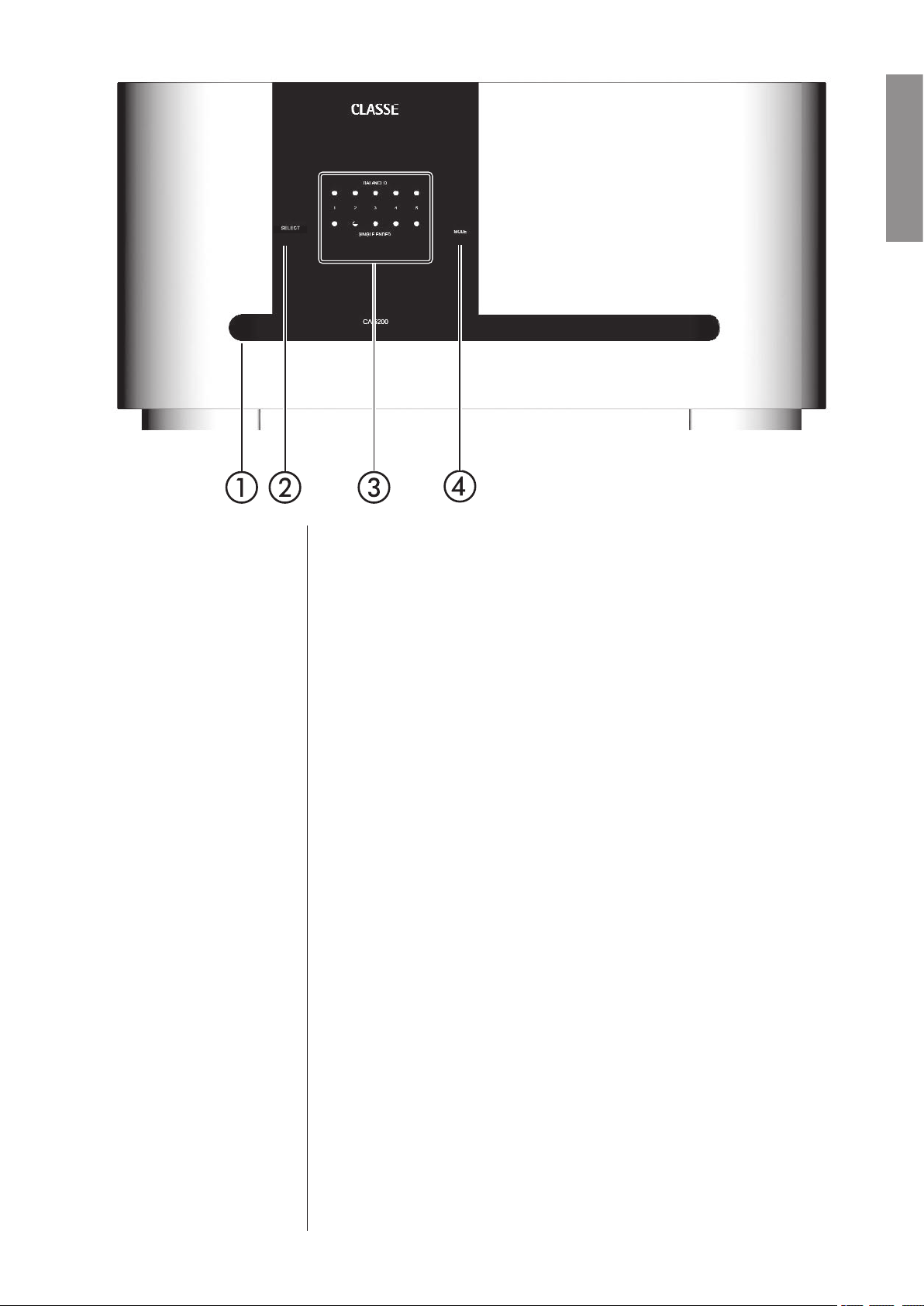
1 Standby button & LED indicator
The front panel Standby button will toggle the amplifier between operate,
its fully operational state, and a standby mode that leaves the amplifier off,
yet ready to respond to system commands via any of the supported control
options (e.g. IR input, DC trigger, CAN Bus, or RS-232).
The current state of the amplifier is indicated by the
the center of the Standby button. The state of this LED indicates the
following:
• on = standby
• flashing (on power-up) =
• off + Channel LED on = operate
• flashing (after power-up) = AC mains voltage out of range
When in standby, the amplifier’s gain stages are powered down. Only a
small power supply and control circuit remain on, consuming relatively
little power. Fortunately, since the output stages by their nature conduct a
great deal of current, they warm up and sound their best very quickly.
If you are not going to use the amplifier for an extended period of time,
perhaps while traveling for a vacation, we suggest you disconnect it from
the AC mains. Please be certain that the amplifier is in standby
disconnecting it from the AC mains.
initialization
LED indicator in
prior to
11
Page 12

ENGLISH
Also, it is a good practice to physically disconnect any and all valuable
electronics from the AC mains during electrical storms, as a lightning
strike anywhere near your home can put a tremendous surge on the AC
mains that can easily damage any piece of electronics, no matter how well
designed and protected. The best protection in the case of severe electrical
storms is to simply remove the electronics from any connection with the
power grid.
2 Select button
The Select button is used (along with the Mode button) when configuring
the amplifier for either balanced or single-ended operation. It is also used
when configuring the turn-on delay or amplifier number for an amplifier
connected to a Classé preamplifier by the DC Trigger or CAN Bus control
systems.
3 Channel status LED indicators
Each amplifier channel has two
Channel LED indicators. They are used to
indicate the use of either balanced (XLR) or single-ended (RCA) inputs for
that channel.
These indicators are also used to indicate fault conditions in your amplifier,
should any ever arise. If a channel’s LED indicators blink red, there is a
problem in that particular channel. If all the
Channel LEDs are blinking
red, there may be a systemic problem that is not specific to a particular
channel.
Caution! If you see any Channel LED Indicator blinking red, please
disconnect the amplifier from the AC mains immediately and
check that all external connections are cleanly made and
secure. If the AC mains are not easily accessible, you can press
and hold the Standby button for three seconds to reset the
amplifier. If no fault is immediately obvious, please call your
authorized Classé dealer for assistance.
4 Mode button
The Mode button is used (along with the Select button) when configuring
the amplifier for either balanced or single-ended operation. It is also
used when configuring the turn-on delay and amplifier number of the
amplifier when it is connected to a Classé preamplifier by the CAN Bus
communications or Trigger systems.
12
Page 13
ENGLISH
Rear Panel
The following descriptions are intended as a quick reference, should you have
any questions about your new product. Please see the next section (entitled
Initial Setup) for specific advice on incorporating your new amplifier into your
system.
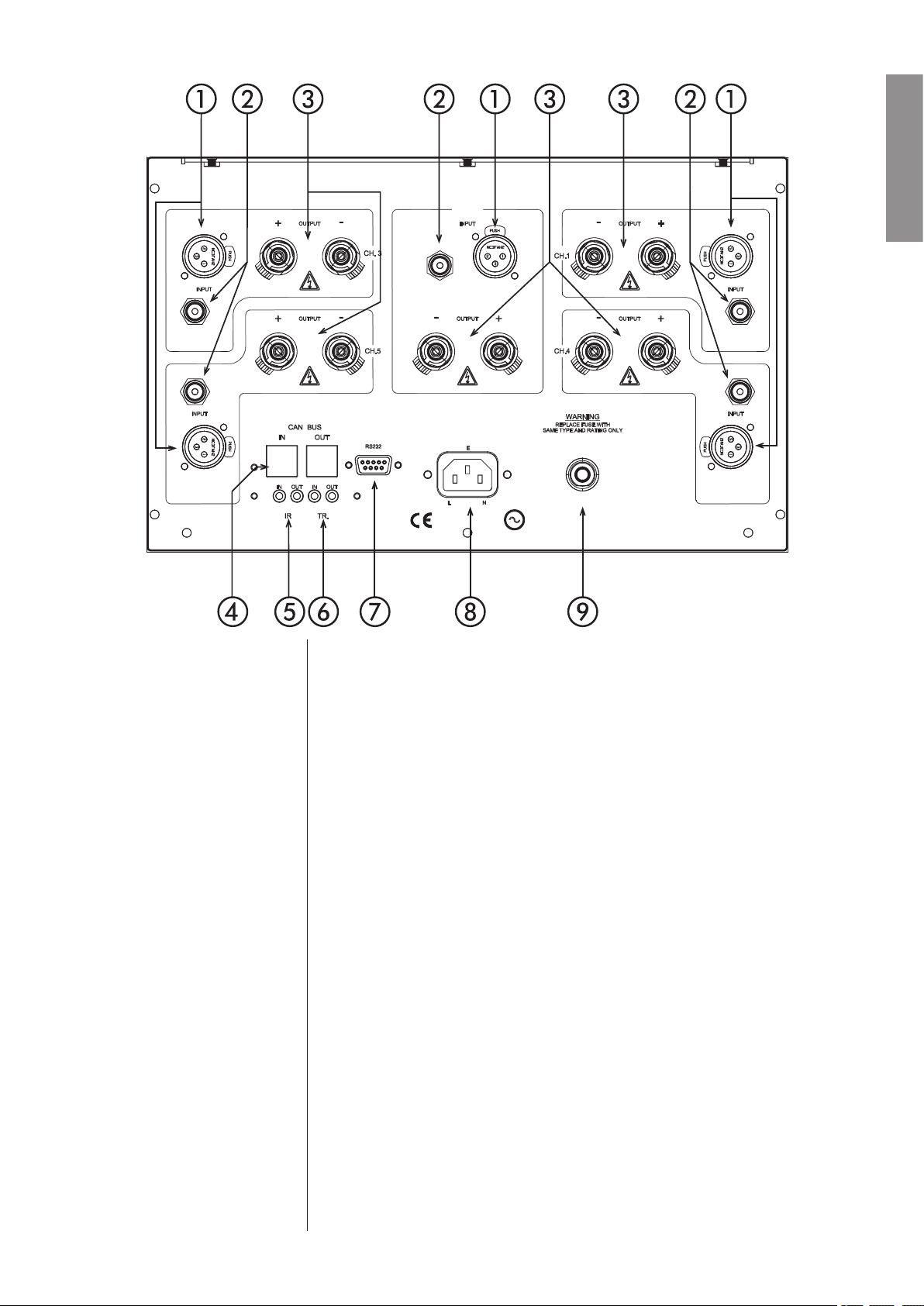
1 Balanced (XLR) Input
Balanced audio interconnections were originally developed in the
professional audio world, for preserving the delicate nuances of extremely
small microphone-level signals. For many years now, they have also been
used by performance-oriented consumer companies like Classé to preserve
every nuance of the finest audio performances in your collection.
Technically, balanced audio interconnections provide two distinct benefits:
they double the signal’s strength as it travels from one component to the
next, increasing the potential signal to noise ratio by 6 dB; they also do an
excellent job of rejecting noise and interference that might otherwise be
picked up between the components, due to either EMI (electromagnetic
interference) or RFI (radio frequency interference). In the world of wireless
telecommunications, there is more potential interference around than ever
before—it makes sense to keep it out of music and movie soundtracks.
13
Page 14

For this reason, we strongly recommend using the balanced analog
interconnections between your Classé components wherever possible.
The pin assignments of these XLR input connectors are:
ENGLISH
Pin 1: Signal ground
Pin 2: Signal + (non-inverting)
Pin 3: Signal – (inverting)
Connector ground lug: chassis ground
These pin assignments are consistent with the standard adopted by the
Audio Engineering Society (AES14-1992).
If you are using your Classé power amplifier with a Classé preamplifier,
you’re all set – just take standard balanced interconnect cables and plug
them in.Then engage that input on the power amplifier by configuring it
as described in Initial Setup.
If you are using another brand of preamplifier, please refer to the operating
manual of your balanced-output preamplifier to verify that the pin
assignments of its output connectors correspond to your amplifier. If
not, have your dealer wire the cables so that the appropriate output pin
connects to the equivalent input pin.
2 Single-Ended (RCA) Input
Single-ended cables using RCA connectors are the most common form
of analog connection used in consumer electronics. When implemented
carefully and with use of high quality interconnecting cables, this standard
can provide excellent performance. Classé has gone to extraordinary effort
to ensure that the single-ended (RCA) inputs of your power amplifier are
as good as possible. However, this connection standard cannot offer the
immunity from interference that balanced interconnection does—hence
our recommendation to use the balanced inputs when possible.
If you elect to use the single-ended inputs of your Classé power amplifier,
you need to engage them by configuring the amplifier as described in
Initial Setup
3 Speaker Outputs
A pair of high quality five-way binding posts is provided for each channel
of the amplifier.
Although the binding posts on your Classé amplifier will accept bare wire
connections, we strongly recommend the use of high quality spade or hook
lugs, crimped and soldered onto the ends of your speaker wires. Using
high quality connectors will ensure that your speaker connections do not
gradually deteriorate from fraying and oxidizing bare wires. It also helps
prevent accidental short-circuits from poorly-terminated connections.
.
14
Page 15
4 Classé CAN Bus Control Ports
These RJ-45 connectors are reserved for future control and communication
applications using Classé Audio’s implementation of the Controller Area
Network (CAN) Bus specification.
ENGLISH
5 IR Input and Output
1/8th
Your Classé amplifier includes two
-inch mini mono-jacks in order to
support the IR remote controls that are ubiquitous today. IR commands
exist for toggling the amplifier between operate
discrete command codes for either operate
and standby, as well as
or standby. These codes may be
used in “macros” for sophisticated remote control systems, facilitating the
control of the amplifier in the larger context of a complete system.
Actually, this IR Input and Output
description is a bit of a misnomer: the
input supplied to these plugs is electrical in nature, not IR. It is obtained by
using standard IR receivers, distribution amplifiers, and emitters (available
from your dealer) to translate the remote’s flashes of infrared light into
corresponding pulses of electricity. The big advantages here include being
able to easily route the signals anywhere they might need to go, and the
reliability of a solid electrical connection.
Since an IR distribution system such as your dealer may design for you
usually must control many products, your amplifier includes both an IR
input (for the control of this product) and an IR output (so as to pass
along the same signal to the next product). This allows you to “daisy chain”
your control wires from one product to the next.
The amplifier is designed to respond to IR commands of 5 Volts DC,
with the tip of the mini mono-plugs defined to be “positive” relative to the
shank of the plug.
15
Page 16

ENGLISH
6 DC Trigger Input and Output
Many audio/video preamplifiers can supply a DC control voltage to
associated equipment in order to induce desired behavior. Your Classé
amplifier can take advantage of these capabilities in order to be switched
between operate
and standby automatically, perhaps in concert with the A/
V preamp itself.
1/8th
Two
(that is, toggling between operate
-inch mini mono-jacks provide this remote-controlled turn-on
and standby) of the amplifier. These jacks
provide a simple pass-through of the control voltage from one to the other,
allowing you to “daisy-chain” a series of amplifiers quite easily.
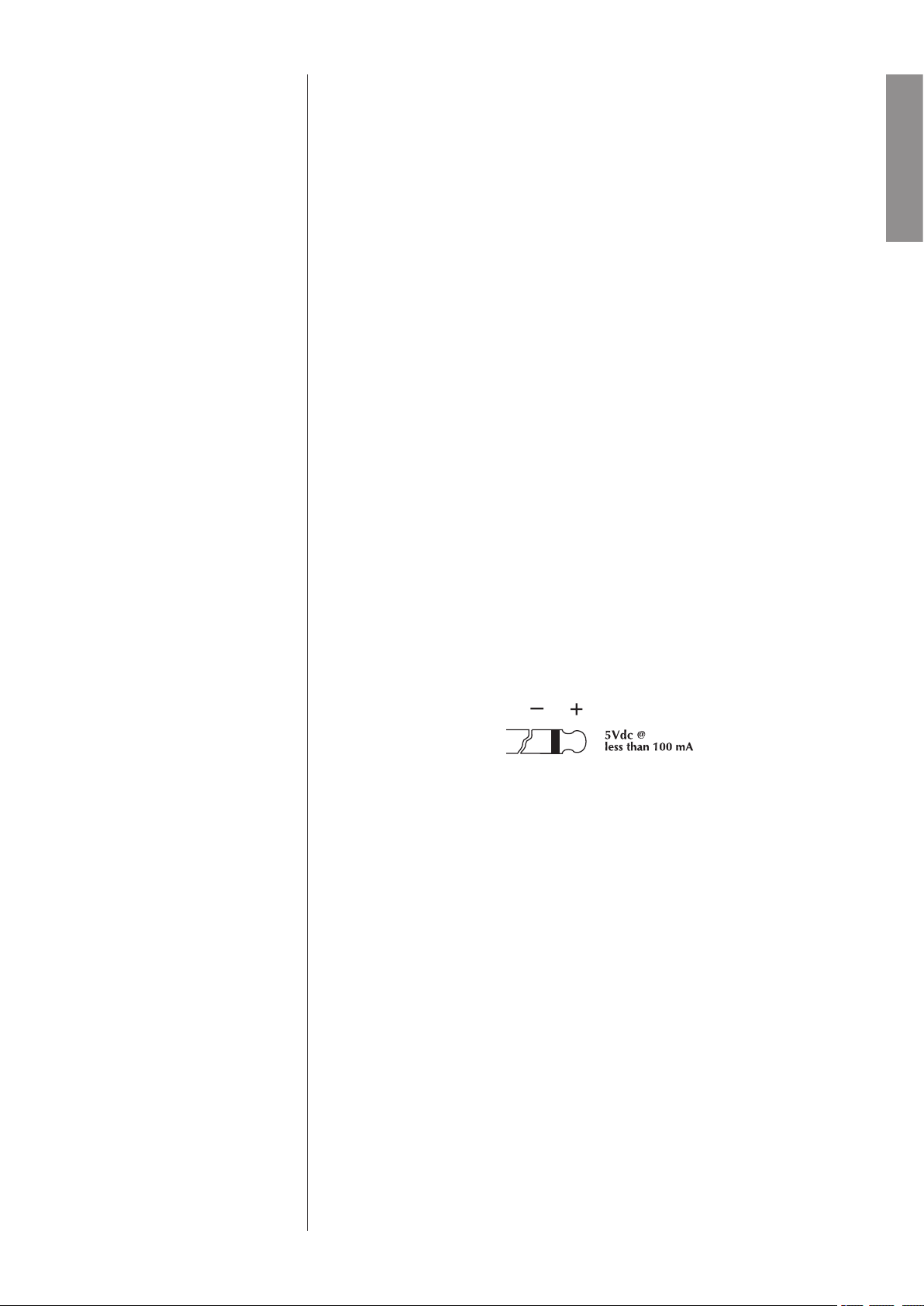
The remote trigger will be operated by the presence of 5–12 Volts DC,
with tip polarity as shown below:
7 RS-232 Control Port
This DB-9 connector has two purposes:
• downloading new operating software into your amplifier (should
new features ever be added, for example)
• for external control of your amplifier by systems such as
i-Command™, AMX® and Crestron
™
For more information, please contact your dealer and ask about home
automation systems.
8 AC Mains Input
An IEC standard power cord is used with the CA-5200. Plug the cord into
the IEC receptacle on the rear panel, and the other end into a suitable wall
outlet.
9 AC Mains Fuse
Your Classé power amplifier has an AC mains fuse,
accessible on the
rear panel. If you suspect that your AC fuse has blown, disconnect your
amplifier from the AC mains, as well as from its input connections and
speaker connections, and refer to the appropriate item of the section
enitled Troubleshooting.
Do not open your amplifier. There are no user-serviceable parts within
this product.
16
Page 17

Danger! Potentially dangerous voltages and current capabilities exist
within your power amplifier, even when disconnected from AC
mains. Do not attempt to open any portion of the amplifier’s
cabinet. There are no user-serviceable parts inside your power
amplifier. All service of this product must be referred to a
qualified Classé dealer or distributor.
ENGLISH
17
Page 18

ENGLISH
Initial Setup
Your new Classé amplifier is quite simple to set up and enjoy. Please follow the
steps outlined below in order to safely set up and use your new amplifier.
Important: The AC mains connection should be the last connection you
make on your new power amplifier. In addition, it is always
a good idea to power up your power amplifier(s) last, after
everything else has been powered up and has stabilized.
Conversely, it is good practice to power the amplifier(s) down
first when shutting down the system, as this prevents any
transients from other components from getting through to
your loudspeakers.
1. Unpack everything according to the included instructions.
Be careful when doing so, as this amplifier is quite heavy.
2. Place your amplifier (be sure to read “Unpacking and Placement”)
and connect it to the AC mains.
This includes deciding on the location, making sure you have adequate
ventilation, and adequate clearance for all the wires behind the amplifier.
Once accomplished, connect the amplifier directly to the AC mains. Do
not use extension cords, as most are not suitable for the current sometimes
required by your amplifier.
.
configuring balanced/
single-ended operation
3. Configure your amplifier.
The Select and Mode buttons are used when configuring your amplifier
for how you would like it to operate.
While in standby, pressing the Select button will cause the Channel LEDs
to light up, indicating how the amplifier is currently configured (either
balanced or single-ended) for each channel.
One of the
may select either balanced or single-ended operation for that channel. Press
the Mode button to toggle between either the balanced mode or the singleended mode of operation, as indicated by which of the two channel LEDs
for that channel is blinking.
Press the Select button again to select the next channel, and repeat the pro
cess until the amplifier is configured as you desire. To finish, continue to
press and release the Select
Make sure you configure the amplifier to use the type of input connection
you will be using for each channel. You may safely use any combination of
single-ended and balanced input connections your system requires.
Channel LED indicators will be blinking, indicating that you
-
button until all the Channel LEDs are off.
18
Page 19

configuring amplifier
turn-on delay/amp no.
In a system that contains multiple Classé amplifiers, you may set the
number of seconds of turn-on delay for each amplifier, allowing each
to turn on in the order you have specified, rather than all at once.
number also acts as an ID when using the CAN Bus. (Having several powerful
amplifiers all turning on at the same time can sometimes stress the AC mains in
your home, potentially leading to nuisance tripping of circuit breakers).
For example, to set the delay for two seconds (and to designate a particular
amplifier as #2):
This
ENGLISH
• Place the amplifier in standby
• Press and hold the Mode
lit. When released, both LEDs will blink to indicate the turn-on
delay and current number of the amplifier (e.g. once to indicate a
one second delay and amplifier #1).
• If you want to change the current amplifier number setting, press
and hold the Mode button again until both Channel LEDs are
on.
• While continuing to hold the Mode button, press the Select
button two times (the same number as the desired delay in
seconds and the amplifier number);
• Release the Mode button. The amplifier will confirm your choice
by blinking the Channel LEDs twice.
4. Make your preamp connections.
With the amplifier in standby (or disconnected from the AC mains),
and using high quality interconnecting cables, make the appropriate
connections with the balanced or single-ended connectors (as configured in
).
Step 3
Make sure all the connections are snug, even if it means gently squeezing
the outer shell of the RCA with pliers and reinserting it to tighten the
connection.
(Standby LED on)
button until both Channel LEDs are
5. Make your speaker connections.
Make the connection between the output terminals of the amplifier and
your loudspeakers, using high quality speaker wires.
Connect the black (–) terminals on the amplifier to the black (–) terminals
on your speaker, and the red (+) terminals on the amplifier to the red (+)
terminals on your speaker.
If bi-wiring, run a total of four conductors between each amplifier channel
and its corresponding loudspeaker: two separate +/– leads, one for the
bass and the other for the mids and treble. Make sure that no wires cross
between the red (+) and black (–) terminals, at either end.
Make sure all the connections are snug and cannot be easily wiggled free,
but do not overtighten them. If you can give the speaker wires a reasonable
tug without movement, they are snug. Further tightening will not make a
better connection, and (taken to the extreme) may damage the connectors.
19
Page 20

6. Double-check all your connections.
We understand that this step sounds redundant, but it is worth the extra
minute or two it might take just to ensure that all connections are correct
and secure before plugging the power cables to the AC outlets..
ENGLISH
7. Turn on all the other components in your system, and then turn
on your amplifier.
It is always good practice to turn any power amplifier on last, and to turn
it off first. Doing so prevents any turn-on/turn-off transients that might
originate in other components from damaging your loudspeakers.
Care and Maintenance
To remove dust from the cabinet of your amplifier, use a feather duster or a lintfree soft cloth. To remove dirt and fingerprints, we recommend isopropyl alcohol
and a soft cloth. Dampen the cloth with alcohol first and then lightly clean the
surface of the amplifier with the cloth. Do not use excessive amounts of alcohol
that might drip off the cloth and into the amplifier.
Caution! At no time should liquid cleaners be applied directly to
the amplifier, as direct application of liquids may result in
damage to electronic components within the unit.
20
Page 21

Troubleshooting
In general, you should refer any service problems to your Classé dealer. Before
contacting your dealer, however, please check to see if the problem is listed here.
1. No sound, and no Channel LED is lit.
• The amplifier is not plugged into the AC mains, or the AC
mains are down (circuit breaker, fuse).
• A brown-out or short-term loss of power might require the
internal microprocessor to be reset. Unplug the unit for at least
30 seconds and then plug it in again and try powering it up.
• The AC mains fuse is blown. See Troubleshooting #4, below (or
contact your Classé dealer).
• The AC mains is out of range. Check the voltage specified on
the rear panel.
2. No sound, and one or more Channel LEDs is blinking red.
• Your protection circuitry may have been engaged. To reset the
amplifier, press and hold the Standby button for 3 seconds
to power down the amplifier. Then disconnect all inputs and
outputs.
• Then try powering up the amplifier by pressing the Standby
button. If the
in the amplifier itself. It should be powered down, disconnected
from the AC mains and taken to your Classe dealer for service.
• If it powers up without any difficulty, power it back down and
reconnect only the inputs. Then restart the amplifier. If it goes
into its blinking protection mode, something is wrong with a
component “upstream” of the amplifier—probably a DC offset
or similar problem. Your amplifier is trying to protect your
loudspeakers (even small amounts of DC can damage woofers in
relatively little time). Try different source components to discover
whether the problem is limited to a single source, or exists all the
time (which would indicate a problem with the preamplifier).
Contact your dealer for help with the appropriate component.
LED continues to blink, there is a fault condition
ENGLISH
3. The amplifier keeps shutting off.
• Make sure you are providing adequate ventilation to the
amplifier, and that the ambient room temperature is below
105°F (40°C).
• Run through the troubleshooting sequence outlined above
(assuming the amplifier is going into its protection mode).
21
Page 22

4. The AC mains fuse is blown.
There is a specific troubleshooting procedure for a blown AC mains fuse,
since this rare occurrence sometimes indicates a significant problem. Please
follow the following steps, in order:
ENGLISH
a. Disconnect your amplifier from the AC mains, as well as from its
input connections and speaker connections, and remove the fuse
cover on the rear of the unit.
b. If the fuse appears to be blown, replace it only with a fuse of
the same type and rating (specified below). Using any other type
of fuse, particularly a larger-value fuse, can result in permanent
damage to your amplifier. If you are uncomfortable replacing the
fuse yourself, contact your Classé dealer for assistance.
Mains voltage: 100/120VAC
Fuse type: MDA slow-blow
Rating: 15A
Mains voltage: 230/240VAC
Fuse type: MDL slow-blow
Rating: 12A
c. After replacing the fuse and fuse cover, reconnect the amplifier to
the AC mains only and turn it on without reconnecting either the
inputs or the speaker wires. If the fuse blows again, disconnect it
from the AC mains and contact your Classé dealer for assistance.
d. If everything seems fine, place the amplifier back into standby
and carefully reconnect the input cable and power the amplifier
up. If the fuse then blows (or the amplifier goes into protection),
you may have a serious fault with your preamplifier/processor.
Contact your Classé dealer.
e. Finally, if everything is still fine, place the amplifier in standby
and carefully reconnect the speaker wires. Check
the speaker wires for possible short circuits. Then power up the
amplifier again. If the amplifier remains functional (the fuse
does not blow), then the original fuse probably blew in order to
protect the amplifier from a large AC mains surge. If it blows
again, contact your Classé dealer for assistance.
5. The Standby LED is flashing quickly, and a Channel LED is flashing
red.
• Try resetting the unit by disconnecting it from the AC mains
power, waiting a few seconds, and reconnecting the amplifier to
power. If this does not solve the problem, contact your Classé
dealer for assistance.
both ends of
22
Page 23

Specifications
Classé Audio reserves the right to make improvements without notice.
■ Power output 200W/ch continuous rms @ 8Ω
(both channels driven) 370W/ch continuous rms @ 4
■ Frequency response 10Hz – 22kHz (+0/-0.1dB)
10Hz – 155kHz (+0/-3.0dB)
■ Phase better than -10° @ 22kHz
■ Signal-to-noise ratio 108dB
(ref. full ouput, 10Hz – 80kHz)
■ Channel separation better than 80dB @ 20kHz
■ Noise floor (FFT) all peaks less than -95dBV
(10Hz – 80kHz)
■ Distortion (THD + noise) 0.003% @ 8Ω
(unweighted, 1.0Vrms/1kHz input, 10Hz – 500kHz)
■ Voltage gain 29.1dB
■ Sensitivity 1.4Vrms for rated output @ 8Ω
■ Input Impedance 100kΩ
■ Rated power consumption (as per IEC60065 para. 2.3.10) 1056W
■ Idle power consumption 348W
■ Mains voltage specified on rear panel
(cannot be changed by dealer or user)
■ Dimensions (not incl. controls or connectors) Width: 17.5” (445mm)
Height: 8.75” (222mm)
Depth: 21” (534mm)
■ Shipping weight 133 lbs (60kg)
■ Net weight 121 lbs (55kg)
Ω
ENGLISH
.
For more information, see your Classé dealer, or contact:
Classé Audio
5070 François Cusson
Lachine, Quebec
Canada H8T 1B3
Telephone +1 (514) 636-6384
FAX +1 (514) 636-1428
http://www.classeaudio.com
email: cservice@classeaudio.com
Classé and the Classé logo are trademarks of Classé Audio Inc. of Lachine, Canada. All rights
reserved.
i-Command™ is a trademark of Equity International, Inc. All rights reserved.
AMX® is a registered trademark of AMX Corporation of Richardson, TX. All rights reserved.
Crestron™ is a trademark of Crestron Electronics, Inc. of Rockleigh, NJ. All rights reserved.
23
Page 24

ATTENTION : POUR RÉDUIRE LES RISQUES D’INCENDIE ET D’ÉLECTROCUTION,
NE JAMAIS EXPOSER CET APPAREIL À LA PLUIE OU L’HUMIDITÉ.
ATTENTION
RISQUE D’ÉLECTROCUTION
NE PAS OUVRIR
ATTENTION : POUR RÉDUIRE LES RISQUES D’ÉLECTROCUTION, NE JAMAIS
ÔTER LE CAPOT DE L’APPAREIL. AUCUNE PIÈCE ACCESSIBLE PAR L’UTILISATEUR
À L’INTÉRIEUR. CONSULTER UN TECHNICIEN AGRÉÉ EN CAS DE PROBLÈME.
FRANÇAIS
Toute l’équipe Classé a pris un soin particulier pour que cet appareil représente pour vous un véritable investissement. Nous sommes fiers de
vous annoncer que tous les appareils Classé ont reçu officiellement l’agrément des normes de la Communauté Européenne (CE).
Cela signifie que votre appareil Classé répond aux normes de sécurité et de fabrication les plus draconiennes du monde. Le symbole « CE »
signifie que votre acquisition satisfait ou dépasse les normes de la Communauté Européenne quant à sa qualité de fabrication spécifique et
individuelle et au respect total de votre sécurité.
Cet appareil a été testé et satisfait totalement aux normes concernant les appareils numériques de Classe B, selon le chapitre 15 des normes
FCC. Ces limites concernent une protection raisonnable contre les risques d’interférences dans une installation résidentielle. Cet appareil
génère, utilise et peut rayonner une énergie radiofréquence, ce qui, s’il n’est pas installé selon les instructions contenues dans ce manuel,
peut générer des parasites dans les radiocommunications. Cependant, il n’y a aucune garantie que de telles interférences ne se produisent pas
dans certains cas d’espèce. Si vous constatez de telles interférences sur la réception radio ou télévision, ce qui peut être mis en évidence en
éteignant puis rallumant cet appareil, nous vous encourageons à les éliminer en essayant une des procédures suivantes :
• Réorientez ou déplacer l’antenne de réception.
• Éloignez plus les appareils de réception et cet appareil les uns des autres.
• Branchez cet appareil dans une prise d’alimentation secteur d’un circuit différent de celui alimentant les appareils de réception.
• Contactez un technicien agréé radio/TV pour assistance.
ATTENTION : Des modifications sur cet appareil, non expressément approuvées par son constructeur, annulent totalement la
responsabilité de ce dernier et la garantie sur l’appareil.
Les informations contenues dans ce manuel sont sujettes à modification sans préavis. La dernière version de ce manuel (en anglais) est en
permanence disponible sur notre site Internet à l’adresse htpp://www.classeaudio.co
Le symbole de l’éclair terminé par une flèche dans un triangle équilatéral est destiné à alerter
l’utilisateur de la présence d’une tension électrique « dangereuse » non isolée à l’intérieur de
l’appareil, suffisante pour entraîner l’électrocution des personnes.
Le symbole du point d’exclamation dans un triangle équilatéral est destiné à alerter l’utilisateur de
la présence de conseils et indications importantes dans le manuel accompagnant l’appareil.
Le symbole « CE » (ci-contre, à gauche), indique que l’appareil a reçu le total agrément des
normes de la Communauté Européenne concernant ses caractéristiques électromagnétiques
(EMC, Electromagnetic Compatibility) et basse tension (LVD, Low Voltage Directivity).
Tous les appareils Classé sont conçus en totale conformité avec les directives internationales
concernant les restrictions d’utilisation de substances dangereuses (RoHS) pour l’environnement,
dans les équipements électriques et électroniques, ainsi que pour le recyclage des matériaux utilisés
(WEEE, pour Waste Electrical and Electronic Equipment). Le symbole du conteneur à ordures
barré par une croix indique la compatibilité avec ces directives, et le fait que les appareils peuvent
être correctement recyclés ou traités dans le respect total de ces normes.
REMARQUE
24
Page 25

Importantes instructions concernant la sécurité
Attention :
Veuillez lire et observer toutes les instructions et recommandations de ce manuel
d’utilisation, ainsi que celles inscrites sur l’appareil lui-même. Conservez soigneusement ce
manuel d’utilisation.
1. Ne tentez pas de réparer vous-même l’appareil. Ne jamais retirer son capot, pour quelque raison
que ce soit. Il n’y a à l’intérieur aucune pièce susceptible d’être changée ou modifiée par l’utilisateur.
Un appareil ouvert, surtout s’il est encore branché sur le secteur, présente des risques mortels
d’électrocution. Adressez-vous toujours à un technicien qualifié et agréé.
2. Pour éviter tout risque d’incendie et d’électrocution, ne jamais exposer l’appareil à la pluie
ou l’humidité. Si un liquide pénètre à l’intérieur de l’appareil, débranchez-le immédiatement de
l’alimentation secteur et faites-le tout de suite vérifier par un technicien qualifié et agréé.
3. N’installez pas l’appareil près d’une source de chaleur, tel qu’un radiateur, une bouche de chaleur,
etc. et ne le laissez pas exposé aux rayons directs du soleil.
4. Branchez l’appareil sur une source d’alimentation secteur de tension correcte. L’emballage externe
et une étiquette en face arrière, à côté du numéro de série, indique la tension d’alimentation correcte.
Une mauvaise tension d’alimentation peut entraîner une panne importante, et annule la garantie.
5. Le câble d’alimentation secteur doit être disposé de telle manière qu’il ne soit pas écrasé ou
pincé par un quelconque appareil ou objet placé sur son trajet. Ne tirez pas directement sur le
câble pour débrancher la prise. Si le câble d’alimentation présente la moindre détérioration, montrez-le
immédiatement à votre revendeur agréé Classé afin qu’il procède à sa réparation ou son remplacement.
FRANÇAIS
6. Si vous n’utilisez pas l’appareil pendant une période relativement longue (vacances, etc.),
débranchez-le du secteur pour éviter tout problème pouvant survenir d’une éventuelle surtension ou
d’un orage.
7. NE JAMAIS laisser un liquide s’introduire à l’intérieur de l’appareil.
8. NE JAMAIS poser de récipient contenant un liquide sur l’appareil.
9. NE JAMAIS bloquer la ventilation par les ouïes ou les ventilateurs de l’appareil.
10. NE JAMAIS court-circuiter aucun fusible.
11. NE JAMAIS remplacer un fusible par un modèle d’une valeur ou d’un type différents de celui
remplacé.
12. NE JAMAIS tenter de réparer ou modifier soi-même cet appareil. Si un problème survient, contactez
immédiatement votre revendeur agréé Classé.
13. NE JAMAIS exposer l’appareil à des températures extrêmes, trop élevées ou trop basses.
14. NE JAMAIS faire fonctionner cet appareil dans une atmosphère présentant des risques d’explosion.
15. TOUJOURS débrancher un appareil électronique sensible pendant un orage.
Veuillez noter ci-dessous le numéro de série de votre nouveau maillon Classé, pour future référence.
Numéro de série # : ____________________________________
25
Page 26

FRANÇAIS
Sommaire
Bienvenue dans la famille Classé ...................................................................27
Un mot concernant l’installation ............................................................ 27
Déballage et installation ................................................................................28
Déballage de votre amplificateur ............................................................ 28
Installation ............................................................................................. 28
Ventilation ............................................................................................. 28
Installations particulières ........................................................................ 29
Numéro de série .................................................................................... 29
Enregistrez votre achat ! ......................................................................... 29
Tension d’alimentation ........................................................................... 29
Période de rodage/mise en chauffe ......................................................... 30
Veuillez lire ce manuel d’utilisation… .................................................... 30
Caractéristiques particulières de la conception ..............................................31
Conception très sophistiquée des circuits ............................................... 31
D’innombrables tests d’écoute ............................................................... 31
Fiabilité extraordinaire ........................................................................... 32
Protection totale ..................................................................................... 32
Face avant ......................................................................................................33
Face arrière ....................................................................................................35
Réglage initial ................................................................................................40
Configuration des canaux ................................................................ 40
Configuration de l’allumage de l’amplificateur ................................ 41
Entretien & Maintenance ...............................................................................42
Dysfonctionnements ......................................................................................43
Spécifications ................................................................................................45
Dimensions ...................................................................................................46
26
Page 27

Bienvenue dans la famille Classé
Nous vous félicitons pour votre achat d’un maillon Classé. Il représente le
résultat de nombreuses années de perfectionnement, et nous sommes certains
qu’il vous apportera des années de plaisir.
Nous tenons à établir une véritable relation avec nos clients. Aussi veuillez nous
retourner la carte de garantie avant de la remettre dans le carton d’emballage
et l’oublier ! Nous pourrons ainsi vous tenir au courant de toutes les futures
améliorations éventuellement apportées à votre maillon Classé.
Le retour de votre garantie permet également d’enregistrer votre appareil, et
ainsi, si un problème devait se présenter, de bénéficier rapidement et facilement
de la garantie, même si vous avez égaré vos documents d’achat.
Veuillez prendre quelques minutes pour remplir la carte de
garantie et nous la renvoyer dans les plus brefs délais.
Vous trouverez cette carte de garantie à la fin du livret de garantie séparé contenu
dans l’emballage.
FRANÇAIS
Un mot concernant
l’installation
Pour cette raison, nous vous encourageons vivement à
Tous les efforts nécessaires ont été accomplis pour rendre le Classé CA-5200
simple et évident à utiliser.
Cependant, nous n’avons aucun moyen de connaître et évaluer certaines vari
ables telles que la taille et la forme de votre pièce d’écoute, son acoustique et
l’équipement associé avec votre amplificateur. Tous ces facteurs influencent pour
tant la qualité finale de votre système.
demander à votre revendeur agréé de procéder lui-même
à l’installation et au réglage de votre système, car son
expérience, sa compétence et l’utilisation éventuelle de
moyens de mesures peuvent entraîner une différence
fondamentale dans la qualité finale obtenue par votre
système.
-
-
27
Page 28

Déballage et installation
FRANÇAIS
Déballage de
votre amplificateur
Important ! Conservez tous les éléments du carton d’emballage et ce
Installation Il y a deux options pour l’installation de votre amplificateur de puissance : vous
Veuillez déballer soigneusement votre amplificateur de puissance suivant les
instructions fournies, et retirez tous ses accessoires du carton d’emballage. Prenez
garde lorsque vous soulevez l’amplificateur, car il est assez lourd.
dernier pour tout transport futur. Le transport de votre
appareil dans un autre emballage pourrait entraîner des
détériorations à celui-ci, dommages non couverts par la
garantie.
pouvez l’installer près des enceintes acoustiques, ce qui nécessitera une liaison
longue avec le préamplificateur ; ou vous pouvez le placer près du préamplifica
teur, ce qui nécessitera des câbles longs vers les enceintes acoustiques.
Bien que ces deux solutions donnent d’excellents résultats, votre préférence
pourra aller vers la première, et ce pour deux raisons. Premièrement, le
signal se dégrade plus vite lorsqu’il est transmis sous une forme nécessitant
simultanément tension et courant élevés, ce qui sous-entend que les câbles vers
les enceintes acoustiques doivent être les plus courts possible. Deuxièmement,
les amplificateurs de haute qualité utilisent des transformateurs d’alimentation
massifs, qui génèrent tous plus ou moins des champs magnétiques. Idéalement,
ces champs magnétiques doivent être éloignés raisonnablement des maillonssources particulièrement sensibles.
-
S’il est cependant plus facile pour vous d’installer l’amplificateur dans un système
en rack, nous vous conseillons de le placer en bas de ce rack, le plus loin possible
du préamplificateur et des sources électroniques. Le positionnement en bas du
rack assure également une meilleure stabilité physique, compte tenu du poids de
l’amplificateur.
Notez qu’il doit y avoir un espace dégagé suffisant à l’arrière du CA5200 pour le branchement et passage des câbles secteur et de liaison.
Nous vous suggérons de laisser un espace d’au moins 20 cm, y compris
de longueur de câble, pour leur développement correct sans risque de
tension ou de torsion exagérées.
Ventilation Votre amplificateur de puissance Classé génère une certaine quantité de
chaleur, normale pendant son fonctionnement. Assurez donc un espace libre
d’une quinzaine de centimètres au-dessus de son capot, et d’environ 8 cm sur
chacun de ses côtés. Les ouïes d’aération présentes sur le dessus et sur les côtés
doivent être laissées libres de toute obstruction qui risquerait de réduire le flux
d’air traversant le châssis de l’appareil. Evitez de le poser sur une surface molle
(moquette ou tapis, par exemple) qui risquerait également de réduire sa bonne
aération interne.
28
Page 29

Installations particulières De schémas sont inclus dans ce manuel afin de faciliter l’éventuel encastrement
dans un meuble sur mesure (voir
spécialement adapté est disponible en option. Contactez votre revendeur agréé
Classé pour de plus amples informations à ce sujet.
Numéro de série Le numérode série de votre amplificateur de puissance se trouve sur sa face
arrière. Veuillez le noter et le reporter à la fin de la rubrique “ importantes
instructions concernant la sécurité ” de ce manuel d’utilisation, pour toute future
référence.
Enregistrez votre achat ! Puisque vous venez de noter le numéro de série, c’est une excellente chose
pour en profiter pour remplir la carte de garantie. L’enregistrement de votre
achat auprès de nous vous permettra d’être tenus au courant des éventuelles
améliorations et de nombreux autres sujets d’intérêt.
Cela ne vous prendra qu’une minute. Veuillez s’il vous plaît compléter la carte
maintenant. Ensuite, vous allez oublier…
Tension d’alimentation L’amplificateur de puissance CA-5200 est réglé en usine (de manière interne)
sur une tension d’alimentation de 100 V, ou 120 V, ou 230 V, ou 240 V,
suivant le pays dans lequel il a été vendu. (230 V uniquement dans les pays de
la Communauté Européenne, suivant les normes CE en vigueur)
tension d’alimentation ne peut être modifié par l’utilisateur.
Dimensions). Un kit de montage en rack
. Ce réglage de la
FRANÇAIS
Assurez-vous que l’étiquette, sur la face arrière de l’amplificateur de puissance
indique bien la tension correspondant à votre réseau d’alimentation secteur.
Le fait de vouloir faire fonctionner l’appareil sur une autre valeur de tension
d’alimentation peut l’endommager de manière irrémédiable.
Attention : La tension d’alimentation de votre amplificateur de
puissance ne peut être modifiée par l’utilisateur. Il n’existe
aucune pièce à l’intérieur susceptible d’être modifiée par
l’utilisateur. En cas de problème, veuillez vous adresser
immédiatement et exclusivement à un revendeur agréé
Classé.
Si la tension d’alimentation indiquée sur votre amplificateur de puissance est
incorrecte, veuillez contacter votre revendeur agréé Classé.
Le CA-5200 peut aisément être alimenté par une ligne secteur normale de 15
ampères. Mais si d’autres appareils sont branchés sur cette même ligne, leur
consommation supplémentaire doit être prise en compte pour l’ensemble de la
ligne.
29
Page 30

FRANÇAIS
Période de rodage/mise
en chauffe
Le CA-5200 intègre un circuit de protection qui évite à l’amplificateur de
fonctionner sous une tension d’alimentation trop forte ou trop faible.
• À l’allumage : la tension d’alimentation doit se trouver dans une
fourchette d’environ – 15 % à + 10 % de sa valeur nominale, ou
l’amplificateur ne s’allumera pas. Par exemple, un appareil prévu
pour une tension de 120 V nécessite une tension d’alimentation
réelle comprise entre 95 et 135 V pour s’allumer effectivement.
• Surtension pendant le fonctionnement : si la tension
d’alimentation augmente brusquement de 10 % ou plus pendant
le fonctionnement, l’amplificateur se met en mode de protection
puis s’éteint. La diode de mise en veille Standby clignote pour
indiquer la mise en service du mode de protection.
• Sous-tension pendant le fonctionnement : si la tension
d’alimentation diminue de 15 % ou plus, l’amplificateur continue
de fonctionner (car cela ne présente pas de danger particulier pour
lui), mais il ne sera alors pas capable de tenir ses spécifications et
performances normales dans ces conditions. La diode de mise en
veille Standby clignote pour indiquer le problème.
Votre nouvel amplificateur de puissance Classé délivre des performances
exceptionnelles immédiatement. Toutefois, ses performances musicales seront
optimales après qu’il ait atteint sa température normale de fonctionnement et
le “ rodage ” de tous ses composants. Selon notre expérience, ce changement
apparaît au bout de 300 heures, période au-delà de laquelle l’amplificateur
atteint son équilibre thermal parfait et ses condensateurs leur charge optimale.
Une fois cette période initiale passée, les performances de votre nouvel appareil
restent constantes pendant des années.
Veuillez lire ce manuel
d’utilisation…
La seule exception à cette règle concerne la mise en veille ou l’extinction totale de
l’appareil pendant une longue période, qui entraînera son refroidissement total.
Dans ce cas, une brève nouvelle période de “ mise en chauffe ” sera nécessaire
pour obtenir les qualités sonores optimales. À moins que votre amplificateur
ait été stocké dans des conditions inhabituelles, cette nouvelle stabilisation
thermique ne prend que quelques minutes. Heureusement, vous n’aurez pas à
attendre une nouvelle fois la période de rodage initiale de 300 heures !
Prenez le temps nécessaire pour lire ce manuel, et ainsi vous familiariser avec
votre nouvel amplificateur. Nous comprenons que vous êtes pressé de le brancher
et de l’écouter. Cependant, la lecture attentive de ce manuel et des conseils qui
y figurent vous permettra, seule, de découvrir tous les avantages de cette superbe
pièce d’électronique que vous venez de vous offrir. Merci d’avance.
30
Page 31

Caractéristiques particulières
de la conception
Conception très
sophistiquée des circuits
D’innombrables tests
d’écoute
Tous les étages analogiques d’amplification Classé sont basés sur des circuits qui
ont été grandement améliorés au fil des années d’un développement continuel.
En débutant avec des schémas électroniques excellents et en les travaillant
ensuite pendant des années, nous avons pu découvrir des raffinements subtils
mais essentiels, garantissant des performances absolument exceptionnelles
dans une grande variété d’applications. En modifiant une tension ici, ou en
changeant légèrement la valeur d’un composant là, nous avons pu ainsi creuser
une différence essentielle entre une “ bonne ” musicalité et cette musicalité
exceptionnelle.
Ce niveau de raffinement ne peut venir que de l’expérience et ne saurait être
obtenu par ceux qui passent sans cesse de la dernière notion technique à la mode
à la suivante. Il explique en partie la constance des performances musicales de
tous les appareils Classé (car tous sont basés sur des étages de gain analogiques
similaires) ainsi que l’unanimité de l’excellence des jugements de leurs
propriétaires comme des critiques des magazines spécialisés.
D’excellentes performances mesurées sont le moins que l’on puisse attendre des
appareils de réputation mondiale et, bien sûr, tous les appareils Classé satisfont
aux normes les plus strictes. Cependant, l’expérience nous a montré que cette
excellence technique n’était pas suffisante pour garantir des résultats subjectifs
musicaux dignes de ce nom.
FRANÇAIS
Pour cette raison, tous les appareils Classé sont très soigneusement et
laborieusement contrôlés, pendant tout le processus de leur conception et de
leur fabrication, par des tests d’écoute. Nos oreilles constituent en effet encore
les instruments de mesure les plus précis que nous ayons, et le complément
indispensable des instruments de mesures électroniques. Dans la recherche de
l’optimisation des circuits d’un appareil, ce sont des centaines de décisions basées
sur des impressions subjectives qui sont prises, par exemple pour substituer tel
composant de très haute qualité par un autre.
À titre d’exemple, nous avons ainsi “ écouté ” une demi-douzaine de résistances
à film métallique 0,1 % de la même valeur, mais de fabricants différents. Les
mesures standards donnaient exactement les mêmes résultats en terme de bruit
résiduel, distorsion, etc. Mais, invariablement, c’était la même résistance d’une
marque donnée qui apportait une petite amélioration de la qualité sonore
subjective de l’appareil en cours de développement. Plus rarement, une telle
modification se traduit par une amélioration sonore étonnamment élevée !
En multipliant ces améliorations successives et diverses des douzaines ou même
des centaines de fois, ce qui est fait avant que l’appareil en cause entre réellement
en production, la différence de qualité sonore finale est tout simplement
remarquable. Voilà pourquoi des tests d’écoute soignés et répétés constituent
pour nous le complément indispensable à notre solide expérience technologique,
toutes choses que vous êtes en droit d’attendre d’une marque comme Classé.
31
Page 32

Fiabilité extraordinaire Un des autres avantages de travailler depuis de nombreuses années sur des
circuits électroniques sophistiqués, maintes et maintes fois améliorés, concerne
l’expérience que nous avons de leur fiabilité à long terme.
En utilisant uniquement des composants de très haute qualité, et en connaissant
parfaitement leur comportement face à un vieillissement accéléré ainsi que réel,
nous pouvons concevoir des appareils dont nous sommes certains de la résistance
à l’épreuve du temps.
Nous sommes ainsi convaincus que votre nouveau maillon Classé vous donnera
des années de plaisir musical sans aucun problème, comme tous les précédents
appareils Classé en donnent à leurs propriétaires.
FRANÇAIS
Protection totale Enfin, votre appareil Classé intègre de nombreux circuits de protection, tous
destinés à protéger à la fois l’amplificateur et vos enceintes acoustiques contre les
aléas de fonctionnement les plus dangereux. En plus, ces circuits de protection
ne dégradent en rien les performances normales de l’amplificateur, mais
éteignent simplement l’amplificateur s’il se trouve confronté avec des conditions
dangereuses. Ces conditions sont :
• Surcharge en sortie
• Ecrêtage
• Courant continu offset
• Tension d’alimentation secteur (hors des tolérances normales)
• Températures de fonctionnement excessives
Si une telle condition survient (chacune peut nuire à l’amplificateur et
certainement aux enceintes acoustiques), l’amplificateur se coupe immédiatement.
Dans ce cas, les indicateurs par diodes LED clignoteront jusqu’à ce que le défaut
disparaisse, puis l’amplificateur se remettra en marche. Si le défaut est spécifique
à un canal, seules les diodes de ce canal clignoteront en rouge ; si le défaut n’est
pas imputable à un canal précis (tension d’alimentation trop faible, par exemple),
la diode de mise en veille Standby clignotera.
32
Page 33

Face avant
1 Touche de mise en veille Standby et diode LED indicatrice
La touche de mise en veille Standby de la face avant permet de basculer
l’amplificateur entre son mode de fonctionnement normal et son mode de
veille Standby qui “ éteint ” l’amplificateur tout en lui permettant de réagir
aux différents modes d’allumage qu’il supporte (télécommande infrarouge,
commutation par courant continu DC Trigger, prise bus CAN, ou prise
RS-232).
FRANÇAIS
Le mode de fonctionnement courant de l’amplificateur est indiqué par
la diode LED de la touche Standby, en face avant, avec les variations de
couleur suivantes :
• en service
• clignotement (à l’allumage) = initialisation des circuits
• extinction + diode LED
Channel allumée = fonctionnement normal
• clignotement = tension d’alimentation secteur
(après l’allumage) hors limites autorisées
En mode de veille Standby, les étages de gain de l’amplificateur sont
éteints. Seuls une petite partie de l’alimentation et les étages de contrôle
restent sous tension, consommant relativement peu d’énergie électrique.
Heureusement, comme les étages de sortie nécessitent par nature beaucoup
de courant, leur température de fonctionnement idéale est très vite atteinte,
tout comme, parallèlement, la meilleure musicalité possible.
Si vous ne comptez pas utiliser l’amplificateur pendant une période assez
longue, voyage ou vacances par exemple, nous vous recommandons de
débrancher son alimentation secteur. Vérifiez bien que l’amplificateur est
en mode de veille Standby avant de débrancher son alimentation.
(on) = mise en veille standby
33
Page 34

FRANÇAIS
C’est aussi une excellente habitude que de débrancher physiquement du
secteur tous les appareils électroniques sophistiqués pendant un orage, car
ses éclairs peuvent entraîner une surtension secteur importante capable
de dépasser les limites d’un simple interrupteur général secteur. Une
telle surtension (qui peut atteindre plusieurs centaines de volts) peut
endommager n’importe quel appareil électronique, quelles que soient sa
robustesse et sa qualité de fabrication. La meilleure protection pendant un
orage consiste donc purement et simplement à couper “ physiquement ”
l’alimentation secteur.
2 Touche de sélection Select
La touche Select (en liaison avec la touche Mode) est utilisée pour
configurer les canaux de l’amplificateur suivant qu’ils fonctionnent en
mode symétrique ou asymétrique. Elle permet également de configurer
la séquence d’allumage de plusieurs amplificateurs Classé reliés à un
préamplificateur Classé via la prise Bus CAN ou les prises de commutation
Trigger.
3 Diodes indicatrices LED des canaux
Chaque canal de l’amplificateur possède deux diodes LED indicatrices
de son fonctionnement. Elles indiquent l’utilisation, soit des entrées
symétriques (XLR), soit des entrées asymétriques (RCA), et ce pour chaque
canal.
Ces diodes vous avertissent également d’un éventuel problème de
fonctionnement - ce qui n’arrivera sûrement jamais. Si une diode LED,
sur un canal, se met à clignoter en rouge, c’est qu’il existe un problème
particulier sur ce canal. Si toutes les diodes
rouge, c’est qu’il y a un problème général non spécifique à un seul canal.
Attention ! Si une diode Channel LED se met à clignoter en rouge,
débranchez immédiatement l’amplificateur de son
alimentation secteur. Vérifiez que tous les branchements,
en entrées comme en sorties, sont parfaitement effectués et
sûrs. Si la prise d’alimentation secteur n’est pas facilement
accessible, vous pouvez presser et maintenir la pression sur
la touche de mise en veille Standby pendant trois secondes
pour réinitialiser l’amplificateur. Si le problème ne vous
apparaît pas facilement et immédiatement, ne tentez rien
mais veuillez contacter votre revendeur agréé Classé.
4 Touche Mode
La touche Mode est utilisée (en liaison avec la touche Select) pour
configurer les canaux de l’amplificateur suivant qu’ils fonctionnent en
mode symétrique ou asymétrique. Elle permet également de configurer
la séquence d’allumage de plusieurs amplificateurs Classé reliés à un
préamplificateur Classé via la prise Bus CAN ou les prises de commutation
Trigger.
Channel LED clignotent en
34
Page 35

Face arrière
Les descriptions qui suivent sont conçues pour vous servir de guide instantané
en réponse aux questions que vous pourriez vous poser concernant votre
nouvel appareil. Veuillez vous reporter au chapitre suivant (titré
pour de plus amples précisions, et pour l’intégration parfaite de votre nouvel
amplificateur dans votre système.
Réglage initial)
FRANÇAIS
1 Entrée symétrique (XLR)
Les branchements audio symétriques ont été développés à l’origine pour le
monde professionnel, afin de préserver les délicates nuances des très faibles
signaux fournis par les microphones. Depuis plusieurs années maintenant,
ils sont également utilisés par les constructeurs réputés comme Classé, pour
préserver chaque nuance des plus belles performances de vos sources audio.
Techniquement, les liaisons audio symétriques apportent deux avantages
distincts : elles doublent la force du signal lorsqu’il voyage d’un maillon
à un autre, améliorant le rapport signal-bruit de 6 dB ; elles fournissent
également un excellent travail pour la réjection de tous les bruits parasites
et des interférences pouvant être captées entre les maillons, que ce soit
des interférences électromagnétiques (EMI) ou de fréquences radio (RFI).
Dans notre monde moderne constellé de liaisons sans fil, le nombre
d’interférences potentielles flottant autour de nous est incroyablement plus
élevé qu’il y a quelques années – ce qui revêt une importance particulière
pour profiter au mieux de nos musiques et bandes sonores de films
préférées.
35
Page 36

Pour cette raison, nous vous recommandons vivement d’utiliser les liaisons
symétriques entre tous vos maillons Classé, à chaque fois que cela est
possible.
FRANÇAIS
Le brochage des prises femelles
Broche 1 : masse du signal
Broche 2 : Signal + (non inversé)
Broche 3 : Signal – (inversé)
Couronne externe de la prise : masse du châssis
Ce brochage est conforme à la norme édictée par l’Audio Engineering
Society (AES).
Si vous utilisez votre amplificateur Classé avec un préamplificateur
Classé, il n’y a aucun problème. Achetez simplement un câble de liaison
symétrique standard, et branchez-le ! Vous devrez simplement configurer
l’amplificateur pour lui indiquer que vous utilisez ses prises symétriques,
comme décrit dans le chapitre suivant
Si vous utilisez un préamplificateur d’une autre marque, veuillez vous
reporter à son manuel d’utilisation pour vérifier que le brochage de ses
prises de sortie symétriques est bien identique à celui de l’amplificateur.
Dans le cas contraire, demandez à votre revendeur qu’il vous fabrique les
câbles symétriques spécialement adaptés à votre liaison.
2 Entrée asymétrique (RCA)
Les câbles de liaison asymétriques utilisant des prises RCA sont encore
les plus répandus pour les liaisons analogiques des appareils électroniques
grand public. Lorsqu’ils sont soigneusement utilisés et choisis avec du câble
et des prises de haute qualité, ils fournissent d’excellentes performances.
Classé a d’ailleurs déployé des efforts inhabituels pour que les prises
asymétriques (RCA) de votre amplificateur soient les meilleures possible.
Cependant, ce type de connexion ne peut offrir la même immunité
contre les parasites externes qu’une liaison symétrique – d’où notre
recommandation précédente pour l’utilisation des liaisons symétriques dès
que cela est possible.
XLR d’entrée est le suivant :
Réglage initial.
36
Si vous décidez d’utiliser les entrées asymétriques de votre amplificateur de
puissance Classé, vous devez le configurer comme indiqué dans le chapitre
suivant
3 Sorties enceintes acoustiques (Speakers)
Deux paires de prises vissantes acceptant cinq types de connexion différents
sont fournies, pour chaque canal de l’amplificateur, afin de faciliter un
éventuel “ bi-câblage ”.
En pratique, le bi-câblage nécessite deux paires de câbles (de préférence
identiques) entre chaque canal de l’amplificateur et son enceinte acoustique
correspondante. Dans la plupart des cas, l’amélioration subjective constatée
concerne le niveau plus grand de détails reproduits et de transparence,
résultant de l’envoi de signaux séparés aux deux sections du filtre de
l’enceinte alimentant leur haut-parleur respectif.
Réglage initial.
Page 37

(La majorité des enceintes acoustiques haut de gamme propose désormais deux
paires de connecteurs correspondant chacune à une section du filtre intégré,
l’une destinée à alimenter uniquement le haut-parleur de grave, et l’autre
la section médium-aigu, composé d’un ou plusieurs haut-parleurs pour la
reproduction du médium et de l’aigu.)
Bien que les bornes vissantes de votre amplificateur Classé acceptent
directement du fil nu de forte section, nous vous recommandons vivement
d’utiliser des connecteurs-fourches, sertis et/ou soudés directement sur les
extrémités des câbles. L’utilisation de tels connecteurs de très haute qualité
vous garantit que les contacts ne se détérioreront pas progressivement, par
oxydation des brins nus des conducteurs. Elle permet également d’éliminer
les risques de court-circuit constatés avec de mauvaises connexions par fils
nus uniquement.
4 Prises de commande Classé CAN Bus
Ces prises de type RJ-45 sont réservées pour de futures applications
concernant le contrôle et la communication entre maillons.
5 Entrée et sortie IR (infrarouge)
Votre amplificateur Classé intègre deux prises
capables de véhiculer les signaux infrarouge de télécommande très
répandus aujourd’hui. De tels signaux infrarouge permettent de
basculer l’amplificateur entre son mode de veille Standby
fonctionnement normal, et peuvent également transmettre tous les autres
ordres infrarouge d’allumage-extinction. Ces codes peuvent également être
intégrés dans des macrocommandes sophistiquées pour le contrôle total de
séquences de commande de l’installation complète.
mini mono-jacks
et son mode de
FRANÇAIS
En fait, l’expression “ Entrée et sortie IR ” est inadaptée : le signal envoyé
via ces prises est électrique, et non infrarouge. Il est obtenu par des
récepteurs, distributeurs ou émetteurs (disponibles chez votre revendeur
agréé) qui transforment les impulsions de lumière infrarouge en impulsions
électriques correspondantes. Le grand avantage de cette conversion est
de pouvoir ensuite véhiculer ces signaux par câble où bon vous semble
sans risque de les voir disparaître grâce à la fiabilité de la liaison purement
électrique.
Parce que le système de commande infrarouge conçu par votre revendeur
commandera certainement plusieurs appareils, votre amplificateur propose
à la fois une entrée (pour le contrôle de cet amplificateur) et une sortie
(pour le contrôle d’autres maillons). Les signaux de commande peuvent
ainsi passer d’un appareil à l’autre, selon le principe “ daisy chain ” (comme
les lampes d’une guirlande).
L’amplificateur peut recevoir des tensions de commande (trigger) de type
5 volts continu, la pointe des prises mini-jacks étant le positif de ce signal,
par rapport au corps « négatif » de la prise.
37
Page 38

6 Entrée et sortie commutation Trigger
La plupart des préamplificateurs audio/vidéo possèdent un système
de commande par tension continue permettant de modifier l’état de
fonctionnement des maillons associés. Votre amplificateur Classé sait tirer
parti de cette possibilité pour passer de son mode de veille Standby
fonctionnement normal, peut-être simultanément avec le préamplificateur
A/V lui-même.
à son
FRANÇAIS
Deux prises
commutation veille/marche de l’amplificateur. Ces prises véhiculent la
tension de commutation dans l’amplificateur sans la modifier, afin par
exemple de commuter simultanément plusieurs amplificateurs selon le
mode “ daisy chain ”.
La commutation est activée en présence d’une tension continue comprise
entre 5 et 12 volts, le câble des prises jacks étant le suivant :
7 Prise de commande RS 232
Cette prise a deux rôles :
• charger un nouveau programme de gestion du fonctionnement
dans votre amplificateur (lorsque de nouvelles fonctions lui sont
ajoutées, par exemple)
• pour le contrôle externe de l’amplificateur par des systèmes de
pilotage comme les modèles AMX® et Crestron™
Pour de plus amples informations sur concernant les systèmes
d’automatisation totale, veuillez contacter votre revendeur agréé.
mini mono-jacks fournissent la tension nécessaire à cette
8 Prise d’alimentation secteur AC Mains
Le CA-5200 utilise un câble d’alimentation secteur normalisé IEC.
Branchez ce câble IEC dans la prise correspondante à l’arrière de
l’amplificateur, puis ensuite son autre extrémité dans une prise
d’alimentation secteur murale.
9 Fusible d’alimentation secteur AC Mains Fuse
Votre amplificateur de puissance Classé est équipé d’un fusible de
protection générale d’alimentation secteur, accessible en face arrière. Si
vous suspectez ce fusible d’avoir fondu, débranchez votre amplificateur
de l’alimentation secteur, ainsi que ses prises d’entrée et câbles d’enceintes
acoustiques, puis ôtez le couvercle du fusible en face arrière.
Ne jamais ouvrir l’amplificateur. Il n’y a à l’intérieur aucun élément
susceptible d’être changé ou modifié par l’utilisateur.
38
Page 39

Danger ! Il y a à l’intérieur de l’amplificateur des tensions et courants
électriques potentiellement dangereux, même lorsque celuici est débranché de son alimentation secteur. Ne jamais
essayer d’ouvrir tout ou partie du coffret de l’appareil. Il n’y
a à l’intérieur de l’amplificateur aucun élément susceptible
d’être changé ou modifié par l’utilisateur. Toutes les
interventions sur cet appareil doivent impérativement être
confiées à un revendeur ou distributeur agréé Classé.
FRANÇAIS
39
Page 40

FRANÇAIS
Réglage initial
Votre nouvel amplificateur Classé est d’utilisation très simple. Veuillez
simplement suivre les étapes suivantes pour garantir le réglage et l’utilisation sûrs
et efficaces de votre nouvel amplificateur.
Important : Le branchement de l’alimentation secteur doit toujours être le
dernier effectué sur votre nouvel amplificateur. C’est d’ailleurs,
en règle générale, une excellente habitude que celle consistant
à toujours allumer en dernier, dans le système, le ou les
amplificateurs de puissance, après que tous les autres maillons
soient alimentés par le secteur et stabilisés.
De la même manière, prenez l’habitude d’éteindre toujours en
premier le ou les amplificateurs de puissance, ce qui évite aux
enceintes acoustiques de supporter d’éventuels parasites de
commutation lors de l’extinction des autres maillons.
1 Déballez chacun des éléments selon les instructions fournies plus
haut.
Prenez garde au fait que l’amplificateur est particulièrement lourd.
2 Installer l’amplificateur (lire soigneusement, plus haut, les
paragraphes “ Déballage ” et “ Installation ”), et branchez-le sur
son alimentation secteur.
Ceci sous-entend que vous ayez auparavant décidé de l’endroit précis,
vérifié la ventilation correcte autour de l’appareil, du bon passage de tous
les câbles à l’arrière. Branchez ensuite l’amplificateur directement dans
une prise secteur murale. N’utilisez pas de câbles rallonges, qui la plupart
du temps ne sont pas adaptés à la consommation électrique nécessitée par
l’amplificateur.
3 Configurez votre amplificateur.
Les touches Select et Mode vous permettent de configurer votre
amplificateur en fonction de la manière dont vous souhaitez l’utiliser.
Configuration des canaux L’appareil étant en mode de veille Standby, une pression sur la touche
Select allume les diodes d’un canal donné, vous indiquant ainsi quel canal
est en cours de configuration (fonctionnement en mode asymétrique ou
symétrique).
Le clignotement des diodes d’un canal indique que celui va pouvoir être
configuré pour le choix du mode symétrique ou asymétrique. Pressez la
touche Mode pour choisir entre mode symétrique ou asymétrique, suivant
qu’une ou les deux diodes restent allumées.
40
Pressez la touche Select de nouveau pour choisir le canal suivant, et répéter
la procédure pour choisir le mode de fonctionnement. Pour finir, pressez la
touche Select jusqu’à ce que toutes les diodes soient éteintes.
Assurez-vous que l’amplificateur est bien configuré en fonction des entrées
réellement utilisées, ce pour chaque canal. Vous pouvez utiliser n’importe
quelle combinaison de configuration suivant les besoins de votre système.
Page 41

Configuration de l’allumage
de l’amplificateur
Dans les systèmes utilisant plusieurs amplificateurs de puissance Classé,
vous pouvez classer par ordre numérique tous les amplificateurs, qui
porteront alors les numéros #1, #2, #3 et ainsi de suite. Lorsqu’ils sont
reliés à un préamplificateur Classé via la prise CAN Bus ou par commutation
Trigger, ils s’allumeront successivement dans l’ordre de leur numéro, et non
tous en même temps. (Si plusieurs amplificateurs très puissants étaient allumés
en même temps, cela risquerait de surcharger ponctuellement votre réseau
électrique, au point parfois de déclencher le disjoncteur général).
Pour attribuer à un amplificateur donné le numéro #x, par exemple :
• Placez l’amplificateur dans son mode de veille Standby
LED Standby
• Pressez et maintenez la pression sur la touche Mode jusqu’à
ce que toutes les diodes de tous les canaux soient allumées. En
relâchant la touche, les diodes clignotent le nombre de fois
correspondant au numéro de l’amplificateur (par exemple, les
diodes clignotent deux fois pour indiquer l’amplificateur #2).
• Si vous souhaitez changer ce numéro pour l’amplificateur, pressez
et maintenez la pression sur la touche Mode jusqu’à ce que toutes
les diodes soient allumées.
• Tout en maintenant la pression sur la touche Mode, pressez la
touche Select le nombre de fois correspondant au numéro que
vous souhaitez donner à l’amplificateur (3 fois pour ampli #3, 4
fois pour amplis #4, etc.).
• Relâchez la touche Mode. L’amplificateur confirmera alors
votre choix par le clignotement des diodes le nombre de fois
correspondant au numéro choisi.
allumée).
(diode
FRANÇAIS
4 Effectuez les branchements avec le préamplificateur
L’amplificateur étant en mode de veille standby
alimentation secteur, et en utilisant les prises symétriques ou asymétriques
selon la configuration choisie à l’étape 3, effectuez les branchements
appropriés en n’utilisant que des câbles de très haute qualité.
Assurez-vous que toutes les connexions sont parfaites, en resserrant
notamment légèrement les couronnes externes des prises RCA avec des
pinces avant de les insérer dans les prises femelles.
5 Effectuez les branchements avec les enceintes acoustiques
Effectuez toutes les connexions nécessaires entre les sorties de
l’amplificateur et vos enceintes acoustiques, en utilisant des câbles
spécifiques de très haute qualité.
Branchez les prises noires (–) de l’amplificateur sur les prises noires (–) de
vos enceintes acoustiques, et les prises rouges (+) de l’amplificateur sur les
prises rouges (+) des enceintes. En cas de bi-câblage, quatre conducteurs
doivent relier chaque canal de l’amplificateur à son enceinte acoustique
correspondante : soit deux paires de câbles +/– séparées, une pour le grave,
l’autre pour le médium-aigu. Vérifiez bien qu’aucun câble ne soit croisé
entre les prises (+) et (–), à chacune de ses extrémités.
ou débranché de son
41
Page 42

FRANÇAIS
Vérifiez que tous les branchements soient solides et ne puissent se défaire
d’eux-mêmes, mais ne serrez tout de même pas trop fort. Si vous pouvez
tirer raisonnablement sur chaque câble sans qu’il ne présente le moindre
mouvement aux extrémités, la qualité de la liaison est suffisante. Un serrage
trop prononcé n’améliorera pas la qualité des contacts, et peut même, à la
limite, détériorer les prises.
6 Vérifiez deux fois toutes les connexions
Nous savons bien que ce paragraphe peut sembler inutile et agaçant, mais
il n’est pourtant jamais inutile de dépenser une ou deux minutes pour bien
vérifier chaque connexion, et éventuellement vérifier puis modifier celles
qui semblent de qualité précaire.
7 Allumez tous les maillons du système, puis allumez l’amplificateur
C’est une excellente habitude à prendre que d’allumer toujours en dernier
le ou les amplificateurs de puissance, et également de les éteindre les
premiers. Cela évite les bruits parasites pouvant survenir à l’allumage/
extinction de certains maillons, qui peuvent alors atteindre et endommager
les enceintes acoustiques.
Entretien & Maintenance
Pour enlever la poussière sur le coffret, utilisez un plumeau ou un fin tissu non
pelucheux. Pour retirer la saleté ou des traces de doigt, nous recommandons
uniquement un chiffon doux légèrement imbibé d’alcool isopropyle. Imbibez
uniquement le chiffon d’alcool, avant de le passer doucement sur la surface de
l’amplificateur. Ne pas utiliser trop d’alcool afin qu’il ne puisse en aucun cas
s’égoutter du chiffon.
Attention ! Ne jamais, en aucun cas, appliquer directement de produit
liquide sur l’amplificateur, car un liquide quel qu’il soit
introduit dans l’appareil peut endommager gravement et
irrémédiablement celui-ci.
42
Page 43

Dysfonctionnements
En règle générale, consultez toujours votre revendeur agréé Classé en cas de
problème. Avant cela, toutefois, vérifiez si le problème rencontré n’est pas évoqué
ci-après. Essayez alors la ou les solutions proposées. Si rien ne résout votre
problème, consultez votre revendeur agréé Classé.
1 Pas de son, et les diodes LED des canaux ne s’allument pas.
• L’amplificateur n’est pas branché dans une prise d’alimentation
secteur, ou l’alimentation n’est pas effective (disjoncteur, fusible
fondu).
• Un problème ponctuel de perte de tension ou de puissance
nécessite la remise à zéro du processeur interne. Débranchez
l’appareil pendant au moins 30 secondes, puis rebranchez-le et
allumez-le.
• Le fusible d’alimentation secteur est fondu. Voir le problème
de fonctionnement #4 ci-dessous (ou contactez votre revendeur
Classé).
• La tension d’alimentation n’est pas correcte. Vérifiez la tension
d’alimentation requise sur la face arrière de l’appareil.
2 Pas de son, et une ou plusieurs diodes LED des canaux clignotent
en rouge.
• Le circuit de protection est entré en service. Pour réinitialiser
l’amplificateur, pressez et maintenez la pression pendant
3 secondes sur la touche de mise en veille Standby. Puis
débranchez toutes ses prises, en entrées comme en sorties.
• Essayez de nouveau de rallumer l’amplificateur, en pressant la
touche Standby. Si la diode LED continue de clignoter, c’est qu’il
y a un problème de fonctionnement de l’amplificateur lui-même.
Débranchez-le du secteur et portez-le chez votre revendeur agréé
Classé pour vérification.
• S’il fonctionne ainsi sans problème, éteignez-le, rebranchez
toutes les entrées, puis rallumez-le. S’il se remet en mode de
protection (diodes clignotantes), le problème vient d’un élément
du système placé “ en amont ”, probablement une tension
continue parasite ou similaire. Votre amplificateur essaie alors
de protéger vos enceintes acoustiques (même une faible tension
continue permanente peut suffire à endommager définitivement
les haut-parleurs de grave en relativement peu de temps). Essayez
de brancher et débrancher les différentes sources pour déterminer
celle qui est la cause du problème, si cela provient d’un seul
maillon ou survient en permanence (cas du préamplificateur
défectueux). Contactez votre revendeur pour vous aider à
déterminer puis éradiquer la cause de la panne.
FRANÇAIS
3 L’amplificateur reste éteint
• Vérifiez qu’il existe bien une ventilation adéquate autour de
l’appareil, et que la température ambiante de la pièce n’excède pas
40 °C (105 °F).
• Passez en revue les problèmes détaillés ci-dessus (si l’amplificateur
s’est mis en mode de protection).
43
Page 44

FRANÇAIS
4 Le fusible d’alimentation secteur a fondu
La procédure de résolution du problème “ fusible secteur fondu ” est
particulière, d’autant que cet événement – très rare – indique généralement
la présence d’un problème sérieux. Veuillez donc suivre les étapes suivantes,
en respectant bien leur ordre :
a. Débranchez l’amplificateur de son alimentation secteur, de ses
câbles en entrées comme en sorties, et retirez le capot du fusible,
sur la face arrière.
b. Si le fusible est fondu, remplacez-le mais uniquement avec un
fusible exactement de même type et de même valeur. L’utilisation
d’un fusible différente, type ou valeur, et notamment d’un fusible
de valeur plus élevée, peut entraîner des dommages irréversibles
à votre amplificateur. Si ce changement de fusible vous semble
trop compliqué, n’hésitez pas à contacter votre revendeur pour
assistance.
Tension d’alimentation secteur : 100/120 VAC
Type de fusible : MDA à fusion retardée
Valeur du fusible : 15 A
Tension d’alimentation secteur : 230/240 VAC
Type de fusible : MDA à fusion retardée
Valeur du fusible : 12 A
c. Après avoir replacé le fusible et son capot, rebranchez
l’amplificateur
rebrancher aucune de ses entrées et sorties. Si le fusible fond à
nouveau, débranchez l’amplificateur et contactez immédiatement
votre revendeur agréé.
d. Si tout semble se passer normalement, mettez l’amplificateur
dans son mode de veille standby, rebranchez soigneusement
tous les câbles en entrée et rallumez-le. Si le fusible fond à
nouveau (ou que l’amplificateur se met en mode de protection),
le problème – sérieux – vient du préamplificateur/processeur.
Contactez votre revendeur agréé Classé.
e. Enfin, si tout se passe normalement, remettez l’amplificateur
dans son mode de veille standby puis rebranchez soigneusement
les enceintes acoustiques. Vérifiez l’absence de tout courtcircuit aux deux extrémités des différents câbles. Puis rallumez
l’amplificateur. Si le fonctionnement est normal (le fusible ne
fond pas), c’est que le précédent fusible a probablement fondu
pour protéger l’amplificateur d’une importante surtension
secteur. S’il fond à nouveau, contactez votre revendeur agréé
Classé pour assistance.
5 La diode LED de mise en veille Standby bleue clignote rapidement,
puis une ou plusieurs des diodes LED des canaux clignotent en
rouge.
• Essayez de remettre à zéro l’appareil en le débranchant du
secteur, attendez plusieurs secondes puis rebranchez-le. Si cela ne
corrige pas le problème, contacter votre revendeur agréé Classé
pour assistance.
uniquement sur son alimentation secteur, et sans
44
Page 45

Spécifications
■ Puissance de sortie nominale : 200 W/canal RMS en continu @ 8 Ω
370 W/canal RMS en continu @ 4
■ Réponse en fréquence : 10 Hz à 22 kHz (+0/-0,1 dB)
10 Hz à 155 kHz (+0/-3 dB)
■ Phase : inférieure à – 10° (22 kHz)
■ Rapport signal-bruit : supérieur à – 108 dB
(réf. sortie maximum, 10 Hz – 80 kHz)
■ Séparation des canaux : supérieure à 80 dB @ 20 kHz
■ Bruit seuil FFT : toutes crêtes sous – 95 dBv
■ Distorsion harmonique totale + bruit : 0,003 % @ 8 Ω
(non pondéré, entrée 1 Vrms/1 kHz, 10 Hz – 500 kHz)
■ Gain en tension : 29,1 dB
■ Sensibilité : 1,4 Vrms à puissance maximum @ 8 Ω
■ Impédance d’entrée : 100 kΩ
■ Consommation à puissance maximum : 1056 W
(norme IEC60065, par. 2.3.10)
■ Consommation électrique moyenne : 348 W
■ Tension d’alimentation secteur : indiquée sur la face arrière
(ne peut être modifiée par l’utilisateur ou le revendeur
■ Dimensions hors tout : Largeur : 445 mm
(sans boutons ni prises) Hauteur : 222 mm
Profondeur : 534 mm
■ Poids emballé : 60 kg.
■ Poids net : 55 kg.
(10 Hz – 80 kHz)
Ω
FRANÇAIS
)
Toutes ces caractéristiques sont exactes au moment où ce manuel est imprimé.
Classé se réserve le droit d’améliorer ses produits sans préavis.
Pour de plus amples informations, contactez votre revendeur Classé, ou con
tactez :
Classé Audio
5070 François Cusson
Lachine, Québec
Canada H8T 1B3
Téléphone +1 (514) 636-6384
Fax +1 (514) 636-1428
Internet : http://www.classeaudio.com
http://www.classeaudio.com
email: cservice@classeaudio.com
Classé et le logo Classé sont des marques déposées de Classé Audio Inc., Lachine, Canada. Tous droits réservées.
i-Command™ est une marque déposée de Equity International, Inc. Tous droits réservés.
AMX® est une marque déposée de AMX Corporation of Richardson, TX. Tous droits réservés.
Crestron™ est une marque déposée de Crestron Electronics, Inc., Rockleigh, NJ. Tous droits réservés.
-
45
Page 46

Dimensions
46
Page 47

Page 48

Classé Audio
5070 François Cusson
Lachine, Quebec
Canada H8T 1B3
+1 (514) 636-6384
+1 (514) 636-1428 (fax)
http://www.classeaudio.com
email: cservice@classeaudio.com
Copyright © 2005 Classé Audio Inc. Printed in Canada.
v2.1 110405
 Loading...