

Page 1

d/emploi
Manual
Istruzioni
de
instrucciones
per
J'uso
MZ55
AM/FM
RADIO
REPRODUCTOR
NAuTICO
RADIO
MARITTlMO·
MARINE
CO
•
AM/FM-LECTEUR
•
DE
CON
RADIO
•
AM/FM
CON
PLAYER
CD
MARIN
DISCOS
DE
COMPACTOS
AM/FM
LETIORE
CD
PER
usa
rnJOO~@
DIGITALAUDIO
Page 2

Contents
1.
FEATURES 2
2.
CONTROLS 3
SOURCE UNIT 3
DISPLAY 3
3.
BUnON
Names of the Buttons and their Functions 4
4. PRECAUTIONS 5
5. HANDLING COMPACT DISCS 6
6. DCP (Detachable
7. OPERATIONS 8
Basic Operations 8
Radio Mode Operations 10
CD Mode Operations
a.
TROUBLESHOOTING
9.
WIRE CONNECTIONS
10. ERROR DISPLAYS
11. SPECIFICATIONS
TERMINOLOGY 4
Control
Panel) 7
11
13
14
14
15
•
Visible
•
Rotary
• Z-Enhancer
•
MAGNA
• MfiGI-TUNE®
• Seek
White Negative LCD and White Illuminated
Volume
BASS EX
I Manual Up I Down
for
Easy Operation
with
3 Mode
for
Dynamic
FM
Reception System
Sound
Tuning
Selector
Bass
Tuning
• a-Times Oversampling Digital Filter and
• Preset Station Scan (PS),
• 2-Channel RCA Line Level
• AM 1 Band,
FM
3 bands each 6
• Repeat 1Random Play
• 200W (50 W X
4)
Maximum Power
Automatic
Output
Ilnlro
channels
Music
Output
Store (AS)
Scan
Buttons
Dual1-Bit
DIA
Converters
total 24 channels, Preset
Memory
Function
2
M255
Be
suretounfold
Vel/illel
Cerci6resededesplegaryde
Assicurarsi rij aprire e
deployer
ei VOliS referer a
Jeggerefa{Jag
and
read
the
!a
page
leerlapagina
ina
next
page.
suivante.
siguiente.
success/va.
~
Page 3

Note:
Be suretounfold this page
Remarque:
Nota: Cuando lea los capitulos, despliegue esta pagina y consulte los diagramas.
Nota:
Veuillez deployer cette pageetvous refereraux schemas quand vous lisez chaque chapifre.
Ass/curars}diaprire questa pagfna e fare rifer/mento a quest!
capitola.
and
refertothe front diagrams as you read each chapter.
dfagrammf
UNlOAD FUENTE/
quandosflegge cfascun
[FNC]
[A-M]
[BND]
[RELEASE]
[CD SLOT]
MAGI-TUitE
[DIRECT]
[Z]
[ISR]
[PIA]
D~PLAY/AFRCHEUR/WSUAL~ADOR/D~PLAY
3 M255
Page 4

I
Note:
•Besuretoread
this chapter referringtothe
front diagramsofchapter
"2.
CONTROLS"onpage
Names of the Buttons and their Functions
3.
[RELEASE]
• Press the [RELEASE] button to unlock the
[CD SLOT]
•
CO
insertion slot.
[.]
button
• Ejects a
button
CO
when it is loaded into the unit.
OCP.
[Z] button
• Use the button to select one of the three types
of
sound
memory. (Z-Enhancer)
[lSR] button
• Recalls ISR radio station in memory.
• Press and hold for 2 seconds or longer: Stores
current station into ISR memory (radio mode
only).
[PIA]
• Performs preset scan whileinthe radio mode.
When the button
is performed.
[SCN] button
• Plays 10 seconds of each track whileinthe CD
mode.
characteristics
button
already
is
pressed and held, auto store
stored
in
[
...
/11]
button
• Plays or pauses a CD whileinthe CD mode.
[SS] button
• Press the
button pressed, to turn the screen saver function on or off.
[DIRECT] button
• Stores a station into memory or recall it directly
while in the radio mode.
[<
...],[
• Selects a station while in the radio mode or selects a track when listening to a CD.
• Press and hold the button for 1second or longer
to switch to fast-forward/fast-backward.
[ROTARY] knob
• Adjust the volume by turning the knob clockwise
or
counterclockwise.
• Use the knob to perform various settings.
[BND] button
• Switches the band,orseek tuning or manual tuning while in the radio mode.
• Plays the first track while in the CD mode.
..
>]
[55]
button while keeping the [BND]
button
[RPT] button
• Plays repeatedly while in the CD mode.
[ROM]
• Performs random play while in the CD mode.
[DISP] button
• Press the [DISP] button while keeping the [BND]
button
button pressed, to switch the display indication
(Main display, clock display).
4 M255
[A-M] button
• Press and hold the button for2seconds orlonger
to switch the MAGNA BASS EX on/off.
• Use the button to switch
treble, balance, fader)
[FNC] button
• Press the button to turn on the power.
Press and hold the buttonfor 1 second or longer
to turn off the power.
• Switches the operation mode among radio and
CD mode.
to
the audio mode (bass,
Page 5

1.
When it is very coldinthe boat and the unit
used soon after switching on the heater, the
disc and the optical components may become
fogged and not operate properly. Wipe fogged
discs with a soft cloth. Fogged optical components will naturally return to normal when the
unit is left for about one hour after which it will
operate normally.
This equipment has been tested and found to comply with the limits for a Class 8 digital device, pur-
15
suant to Part
These limits are designed
protection against harmful interference in a residential installation.
This equipment generates, uses, and can radiate
radio frequency energy and, if not installed and
used
in
accordance with the instructions, may
cause harmful interference to radio communications. However, there
ference will not occur
If this equipmentdoes cause harmful interference
to radio or television reception, which can be determined by turning the equipment off and on, the
user
is
encouraged to consult the dealer or
experienced radiofTV technician for help.
of the FCC Rules.
to
provide reasonable
is
no guarantee that inter-
in
a particular installation.
an
is
2.
When the boatisunderwayinrough water the
sound may skip as a result of intense vibrations and shock.
3.
This
unit
usesaprecision
Even in the event that trouble arises, never
open the case,
lubricate the rotating parts.
USE OF CONTROLS, ADJUSTMENTS,
PERFORMANCE OF PROCEDURES OTHER
THAN THOSE SPECIFIED HEREIN,
RESULT IN HAZARDOUS RADIATION EXPOSURE.
THE
COMPACT
NOT BE
ANYONE EXCEPT PROPERLY QUALIFIED
SERVICE
ADJUSTED
PERSONNEL
disassemble
DISC PLAYER SHOULD
OR REPAIRED BY
mechanism.
the unit,
MAY
I
or
OR
IltUi·';1I@i,t.hfi·Jj'lfi#jfil
CHANGES OR MODIFICATIONS TO THIS
PRODUCT NOTAPPROVED
FACTURER
AND WILL VIOLATE FCC APPROVAL.
WILL
VOID THE WARRANTY
BYTHEMANU·
MODEL
C€
12V
e GROUND EUROPA: AM531-1602kHz
= 15ALoad
THIS
OPERATION
(1)
THIS DEVICE MAY NOT CAUSE HARMFUL INTERFERENCE, AND
(2)
THIS DEVICE MUST ACCEPT ANY INTERFERENCE RECEIVED,
INCLUDING INTERFERENCE THAT
OPERATION.
THIS
SUBCHAPTER J APPLICABLEATDATE OF MANUFACTURE.
CLARION
40
DEVICE
COMPLIES
IS
SUBJECT TO THE FOLLOWING TWO CONDITIONS:
PRODUCTION
CO.,LTD. 50 KAMtTODA, TODA-SHI, SAITAMA-KEN, JAPAN
CLASS1LASER
M255
USA:
AM530-1710kHz/FM
AUSTRALIA:
WITH PART15OF
COMPLIES
87.9-107.9MHz
IFM
AM531-1629kHz/FM
MAY
CAUSE UNDESIRED
WITH DHHS RULES21CFR
B7.5-1OBMHz
THE FCC RULES.
PRODUCT
~
-------
0051
MANUFACTURED:
SERIAL
No.
PE-2692B
722 877
ClarlonCo.,Lld.
MADEINMALAYSIA
Clarion
87.0-10BMHz
I
286-6571-00
Bottom
ViewofSource
Unit
M255 5
Page 6
I
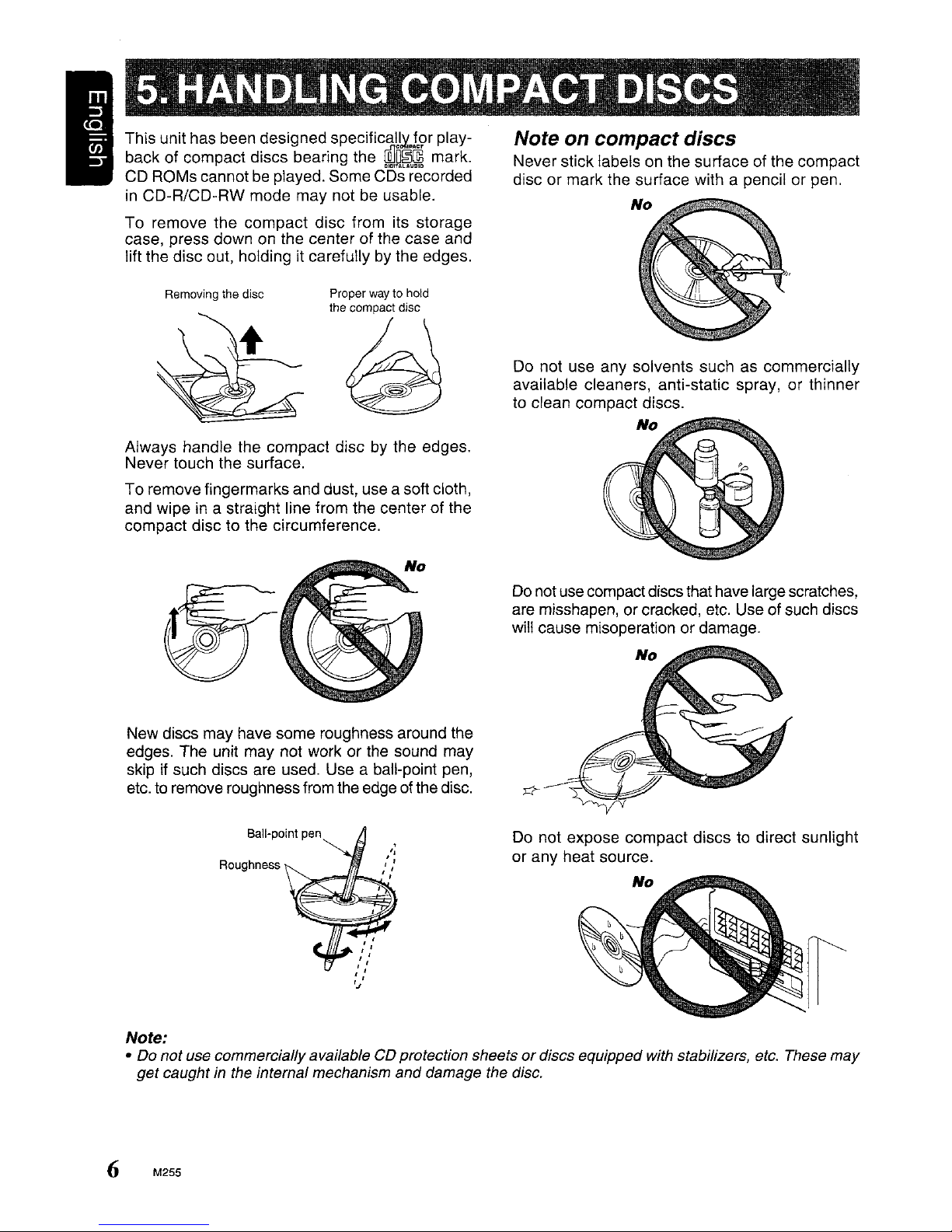
This unit has been designed
back of compact discs bearing the
CD ROMs cannot be played. Some dO's"recorded
in
CD-R/CD-RW mode may not be usable.
To
remove the compact disc from its storage
case, press down on the center of the case and
lift the disc out, holding it carefully by the edges.
specifjcaU~plcs>r
cQ]D~~
play-
mark.
Note on compact discs
Never stick labelsonthe surface of the compact
disc or mark the surface with a pencil or pen.
No
Removing the disc
Proper way to hold
the compact disc
~
Always handle the compact disc by the edges.
Never touch the surface.
To remove fingermarks and dust, use a soft cloth,
and wipe in a straight line from the center of the
compact disc to the circumference.
New discs may have some roughness around the
edges. The unit may not work or the sound may
skip if such discs are used. Use a baH-point pen,
etc.
to
remove roughness from the edge of thedisc.
Do not use any solvents such as commercially
available cleaners, anti-static spray, or thinner
to clean compact discs.
No
Do
notuse compact discsthathavelargescratches,
are misshapen, or cracked, etc. Use of such discs
will cause misoperation or damage.
No
Roughness
Note:
• Do
not
use commercially available CD protection sheetsordiscs equipped with stabilizers, etc. These
get
caught in the internal mechanism and damage the disc.
6
M255
Do not expose compact discs to direct sunlight
or any heat source.
No
may
Page 7

The control panel can
theft. When detaching the control panel, store it
in
the DCP (Detachable Control Panel) case to
prevent scratches.
We
recommend taking the
leaving the car.
be
detached to prevent
OCP
with you when
Removing the DCP
1.
Press the [FNC] button for 1 second or longer
to switch off the power.
2.
Pressinthe [RELEASE] button.
~[RELEA5E]button
f~
*
The
DCPisunlocked
3.
Remove the DCP.
Storing the DCP in the DCP case
Hold the
figure below, and put it into the supplied
(Ensure the DCP is
• The DC? can be damaged by impact. After
removing it, be careful not
ject the unittostrong shocks.
• When the Release button
DC?
cause it to fall. To prevent damage to the
DC?, always store it
ing it. (See figure above.)
• The connector connecting the main unitand
the DC? is
careful not to damageitby pressing on it
with fingernails, pens, screwdrivers, etc.
OCP,inthe orientation as showninthe
OCP
case.
in
the correct orientation.)
to
drop or sub-
is
pressed and the
is
unlocked, the car's vibrations may
in
its case after detach-
an
extremely important part.
Be
I
Attaching the DCP
1. Insert the right side of the
unit.
2.
Insert the left side of the
the main unit.
OCP
OCP
into the main
to attach into
DCP
connector
Note:
•Ifthe
cloth
OCPisdirty,
only.
wipe
off
the
dirt
withasoft,
M255
dry
7
Page 8

IBasic Operations
Note:
Be
suretoread
chapter
this chapter referringtothe front diagrams
"2.
CONTROLS"onpage
of
3.
Lower
unit
ting.Ifthe
up,
den
or
Turning
1. Press the [FNC] button.
2. The illumination and display on the unit light
3. Press and hold the [FNC] button for 1 second
Selecting a
1.
2. Each time you press the [FNC] button, the op-
Note:
•IftheCDmodeisselected whennodiscisinserted,
Adjusting
Turning the [ROTARY] knob clockwise increases
the volume; turning
the volume.
*The volume level
the
volume
off. The
unitispowered
when
the
unitispowered
loud
volume
damage
the
on/off
up. The unit automatically remembers its last
operation mode and will automatically switch
to display that mode.
or longer to turn off the power for the unit.
unit
unit.
level
stores
may
the
before
the
off
harm
power
last
with
back
your
powering
volume
the
volume
on,
the
hearing
mode
Press the [FNC] button to change the opera-
tion mode.
in
eration mode changes
Radio mode
the display shows
mum).
~
CD mode~Radio mode
"NO
the
volume
it
is
from 0 (minimum)to33
counterclockwise decreases
the following order:
DISC".
(maxi-
the
set-
sudand/
...
Setting
The unit provides 3 types of sound tone effects,
stored
':'
The factory default settingis"Z-EHCR OFF".
Each time you press the
fect changes
"Z-ENHANCER
ENHANCER
HANCER1"...
• Z-ENHANCER 1
• Z-ENHANCER 2
• Z-ENHANCER 3
• Z-EHCR
Audio
Press the [A-M] button to select the adjustment
mode. The mode switches as follows each time
the [A-M] button
BASS~TREB~BAL~FAD~Previous mode
'"
The display returnstothe previous mode 7 seconds after the adjustment.
Adjusting
1.
Press the [A-M] button and select "BASS".
2. Turning the [ROTARY] knob clockwise empha-
sizes the bass; turning it counterclockwise at-
tenuates the bass.
~,
Adjusting
1.
Press the [A-M] button and select "TREB".
2.
Turning the [ROTARY] knob clockwise emphasizes the treble; turning it counterclockwise
attenuates the treble.
* The factory default settingis"0". (Adjustment
Note:
• Bass and Treble
enhancer"
the
Z-Enhancer
in
memory. Select the one you prefer.
[Z] button, the tone ef-
in
the following order:
1"~"Z-ENHANCER
3"
~
"Z-EHCR
: bass emphasized
: treble emphasized
: bass and treble emphasized
OFF
mode
The factory default setting
range:
range:
-7to+7)
-7to+7)
is
: no sound effect
adjustments
is
pressed:
the
bass
the
treble
can
onlybeadjusted when the
off.
OFF"~"Z-EN-
is
2"~"Z-
"0". (Adjustment
"Z_
8 M255
Page 9

Basic Operations
Adjusting the balance
1.
Press the
2.
Turning the [ROTARY] knob clockwise emphasizes the sound from the right speaker; turn-
it
ing
from the left speaker.
'"
The factory default settingis"0".
range:L13toR13)
[A~M]
button and select "BAL".
counterclockwise emphasizes the sound
(Adjustment
Adjusting the fader
1.
Press the [A-M] button and select "FAD".
2.
Turning the [ROTARY] knob clockwise emphasizes the sound from the front speakers; turning it counterclockwise emphasizes the sound
from the rear speakers. The line-level outputs
in
are used
settings.
",
The factory default settingis"0".
range:
conjunction with the rear speaker
(Adjustment
F12toR12)
Turning the MAGNA BASS EX on/off
The MAGNA BASS
to provide you with a dynamic sound.
*
The
factory default settingisoff.
Press
and
hold the [A-M] button
longertoturn the MAGNA
in
the display lightsonor
EX
emphasizes deep bass
for
2 seconds
BASSEXand
off.
"M-B
EX"
or
Switching the clock display I
Press and hold the [BND] button, and then press •
the [DI5P] button to switch between the operation mode and the clock display.
Setting the clock
1.
Press and hold the [BND] button, and then
to
press the [DI5P] button
play.
2.
Press and hold the [BND] button, and then
press the [DI5P] button for 2 seconds or longer.
3.
Press the
and MINUTE selection. Then turn the [ROTARY]
minute or counterclockwise to decrease hour/
minute.
4.
Press the [BND] button, then clockisset.
Note:
•Ifyou
setting the clock, the clock setting operation
canceled.
If
you
•
repair,
[<"llI]
or [
knob
clockwise
select another operation
remove the vehicle's battery
the
clock will
reset,soyou
display the clock dis-
...>]button to toggle HOUR
to increase
mode
for
must setitagain.
hour
while
you
a check or
will
are
be
/
Turning the screen saverfunction on
or off
This unitisprovided with the screen saver function. You can turn on or off this function.
If
the button operationisperformed with the screen
saver function on, the operation display corresponding to the button operation is shown for
about 30 seconds and the display returns to the
screen saver display.
*The factory default setting
[55]
Press the
button pressed, to turn the screen saver function
on or off.
button while keeping the [BND]
is
off.
M255 9
Page 10

Radio Mode Operations
I
FM
reception
For enhanced
tuner includes signal actuated stereocontrol and
multipath noise reduction circuits.
FM
performance the MfiGI-
TUNE@)
Listeningtothe radio
1.
Press the [FNC] button and select the radio
mode. then the radio will be
2.
To select a preset band, press the [BNO] button, then select one of the preset bands such
as
FM1,
FM2,
FM3orAM.
is
button
FM1~FM2
3.
Press the
desired station.
Manual
1.
Press the [BNO] buttontoselect the desired
band FM1, FM2, FM3 or
2.
Press and hold the [BNO] button for 2 seconds or longer, then the "MANU"
display, which means that a manual selection
function is
3.
Press the [
in
a station.
Seek
1.
Press the [BNO} button to select the desired
band FM1, FM2, FM3 or AM.
2.Ifthe "MANU" is litinthe display, press and
hold the {BNO] button for 2 seconds or longer.
When the "MANU" display is off, the seek tuning
3.
Press the
seek
pressed, the display will change as:
~FM3
[<<Ill]
~AM
or [
....>]button to tuneinthe
tuning
on.
<<Ill]
or [
....
>]button to manually tune
tuning
is
now available.
[<<Ill]
or [
....
>] button to automatically
in
a station.
on.
Every
~FM1
AM.
time
is
the
[BNO]
lit
in
the
Manual memory
1.
Press the [BNO] button, to select a band you
want to store
2.
Press the [
desired station.
3.
Press and hold one of the [DIRECT] buttons
for 2 seconds or longer to store the current
station into preset memory.
Auto
store
<<Ill]
function
function
in
the memory.
or [
....>]button to tune into a
(Automatic Station Store)
1.
Press [BNO] button to select the desired band
FM1, FM2, FM3 or
2.
Press and hold the
or longer. The stations at which the reception
is
the strongest will be automatically stored
memory.
Notes:
•
When
the
auto
storeisperformed,
viously storedinmemoryatthat positionisoverwritten.
When
the
•
six,
button
Preset
numberofstations
the
previous memory content
willberetained.
scanning
AM.
[PIA]
button for 2 seconds
the
storedisless
for
station
each
pre-
than
direct
(Preset Station Scan)
When the
indicated with preset memory numbers, and the
stations are tuned in for 7 seconds each,
order
button again to cancel the preset scanning mode.
Instant
With this function, a specific radio station can be
recalled from any mode.
[PIA}
buttonispressed, "SCN" will be
in
which they were stored. Press the
station recall (lSR)
in
[PIA]
the
in
Preset
Preset Memory Function can store up to
stations: six stations for eachofFM1,FM2, FM3
and AM.
10
M255
memory
function
24
memory
ISR
1.
Press the [FNC] button, then select the radio
mode.
2.
Select the radio station which you wanttostore
in
the memory.
3.
Press and hold the [ISR] button for 2 seconds
or longer.
Recalling ISR
Press the [ISR] button and the display will show
"ISR". Then the radio station preViously memo-
be
rized will
to disengage the unit from recalling the lSR func-
tion.
selected. Press the [ISR] button again
Page 11

Radio Mode Operations
CD
Mode Operations
Area change
Use this function
stereo
anywhere
Switchable
This boat stereo is initially setto tune in frequency
intervals of
the
standard calibrations in the U.S.
the unit outside
dure to switch
The
table
for
the U.S.
10kHz
below
~
Frequency
spacing
when
you
are using
outside the U.S.
frequency
the
the
frequency range.
lists the frequency specifications
and
other
Initial Setting
(U.S.
standard)
10
kHz
spacing
for
AM
and
200
kHz
When
U.S., usethe following proce-
countries.
New
Setting
(Australia
standard)
9
kHz
New
9
the
boat
for
FM,
using
Setting
(Europe
standard)
kHz
AM
Frequency
range
Frequency
spacing
530
1710
200
to
kHz
kHz
531
1602
50
to
kHz
kHz
531
1602
50
to
kHz
kHz
FM
Frequency
range
87.9
107.9
to
MHz
87.0
to
108 MHz 108 MHz
87.5
to
Loading a CD
Insert aCDinto
the labeled side facing
play, the
Notes:
•
Do
not put your hand, fingers,orforeign objects
into the CD insertion slot.
•
If
a CD has already been loaded, another CD can-
be
not
fully.
• Discs not bearing the
with the unit. CD-ROMs cannot
• Some CDs recorded
be
not
Listeningtothe
Press
the CD will start playing.
the
the
centeroftheCDinsertion slot with
up.
"LOAD" appearsinthe dis-
CD
enters into
inserted.
usable.
[FNC] button to select the CD mode,
the
slot
and
start playing.
Do
not insert another one force-
~Ri~
mark cannotbeplayed
be
played.
in
CD-R/CD-RW mode may
disc
already inserted
I
Switching
Australia
While pressing the
button, then "Australia standard" will be selected.
the
area change
standard (New Setting)
[AM]
button, press
the
[RPT]
Inside U.S. standard (Initial Setting)
While pressing
button, then "U.S. standard" will be selected.
the
[AM]
button, press
the
[SeN]
Europe standard (New Setting)
While pressing
button, then
the
"Europe
[AM]
button, press the [ROM]
standard" willbeselected.
Stopping (Pausing)
While
button will stop
cated.
Press the
mode.
Ejecting
Press the
Note:
• Ifthe ejected CD is left as
• Note that mini CD's will not reload, so make sure
Top
Pressthe [BND] button, then the CD will start playing from the first song (track
the
CDisplaying,
[.-/11]
the
[.]
seconds.
remove them.
function
the
CD
button again to resume the play
CD
button, then theCDwill be ejected.
playback
pressing
and
"PAUSE"
it
is, it will reload after 15
number
the
will be indi-
1).
[.-111]
to
M255
11
Page 12

I
CD Mode Operations
Selecting tracks (Songs)
Press the [<
1Jlo>
<..
..
]or [
..
>]button.
: Playback will start from the next track.
:Playback will start from the beginning
the
track
currently
button is
from the previous track.
pressed
playing.
again, the CD will
When
of
this
play
Fast-forward and fast-backward
Press and hold the
..
> :To fast-forward
<..
:To fast-backward
*For
CD
mode pressing the [<
1 second or longer will move
3 times faster than normal play, and pressing
3 seconds or longer will
faster.
[<..]
or[..>]button.
do
the operation 30 times
..
]or [
..
>]button for
fOliNardorbackward
it
for
Scan play (lntro Music Scan)
AtAudio CD press the [SeN] button, the "SeN" is
lit, then the CD will play the first 10 seconds of
of
each track
button again to disengage the unitfrom scan play.
the whole disc. Press the [SeN]
*A scan play will start from the track foHowing the
one
currently playing.
Repeat play
At Audio CD press the [RPT] button, the "RPT" is
lit, then the track currently playing will play repeatedly. Press the [RPT] button again to disengage the unit from repeat play.
Random play
At Audio CD operation, press the [ROM] button,
the "ROM" is lit, then the entire tracks on the disc
will be played at random. Press the [ROM] button
again to disengage the unit from random play.
12
M255
Page 13

Power does not turn on.
is
(No sound
produced)
Fuse
is
blown.
Replace with a fuse of the same amperage. If
the fuse blows again, consult your store of
purchase.
Compact disc cannot be
loaded.
is
Sound skips or
Sound
is
bad directly after
power is turned on.
Nothing happens when
button are pressed.
Display
is
not accurate.
noisy.
Incorrect wiring.
Another compact disc
already loaded.
Compact disc is dirty.
Compact disc
scratched or warped.
Water droplets may form
the internal lens.
The microprocessor has
malfunctioned due to noise,
etc.
DCP or main unit connectors Wipe the dirt off with a soft cloth moistened with
are dirty. cleaning alcohol.
is
is
heavily
Consult your store of purchase.
Eject the compact disc before loading the new
one.
Clean the compact disc with a soft cloth.
Replace with a compact disc with no scratches.
on
Let dry for about 1 hour with the power on.
Turn off the power, then press the
button and remove the DCP.
Press the reset button for about 2 seconds with
rod.
a thin
Reset button
[RELEASE]
M255
13
Page 14

IHead Unit Harness Wire Connections
+
Yellow
Red
Black
Blue
OrangelWhite
BluelWhite
Grey
Grey/Black
White
White/Black
Purple
Purple/Black
Green
Green/Black
12VDC
12VDC
+
Ground
Power
Dimmer
Amplifier
Right Front
Right
Left Front
Left
Right
Right
Left
Left
Constant
Switch Lead/Accessory
Antenna
Remote
Front
Speaker
Front
Speaker
Rear
Speaker
Rear
Speaker
Rear
Speaker
Rear
Speaker
Turn-on
Turn-on
Speaker
Speaker
Power
(+)
(-)
(+)
(-)
(+)
(-)
(+)
(-)
Source/Memory
*Note: All wire 1unctions may not
be
available on the head
unit
RCA Connections
Rear
Right
Left
Rear
•
Red
White
To
protect the system, this unit has been equipped with self diagnostic functions.Ifa fault
arises, a warning is issued by various· error displays. Follow the corrective measures and
remove the fault.
ER2
ER3
Line Level Output (Full Range)
Line Level Output (Full Range)
This
error display indicates that a fault has arisen in the
mechanism of the source unit (for example,
ejected).
~
Check
This error display indicates that
of a scratched disc
~
Check
the
source unit.
the
compact disc.
the
pickup focus is off because
or
some otherfactor during source unit play.
the
disc cannot be
ER6
14 M255
This indicates that the CD's
read,
for
example because the selected disc is upside-down.
TOC
(tableofcontents) cannot
be
Page 15

FM
tuner
Frequency Range: 87.9 MHz to 107.9 MHz
Usable Sensitivity:
50 dB QUieting Sensitivity: 17 dBf
Alternate Channel Selectivity: 75 dB
Stereo Separation
Frequency Response (±3 dB): 30 Hz to 15 kHz
AM
tuner
Frequency Range:
AM
530 kHz to 1710 kHz
11
dBf
(1
kHz): 35 dB
General
Power Supply Voltage:
to
14.4 V DC (10.8 V
tive ground
Current Consumption: Less than 15 A
Speaker Impedance: 4
Weight: 2.42 lb.
Dimensions:
178 mm Width X 50
Depth
15.6 V allowable), nega-
Q
(4
0 to 8 0 allowable)
(1.1
kg)
mm
Height X 152
I
mm
Usable Sensitivity: 25
CD
player
System: Compact disc audio system
Usable Discs: Compact disc
Frequency Response:
Signal-to-Noise Ratio: 100 dB
Dynamic Range: 95 dB
Harmonic Distortion:
Audio
Maximum Power Output: 200 W (50 W X 4 ch)
Continuous Average Power Output:
17 W X
Bass Control Action (100 Hz): ±14 dB
Treble Control Action (10 kHz): ±14 dB
Line Output (with AlC 1kHz, 10 kO): 1.7 V
4,
into 40,20 Hz to 20 kHz, 1%THD
!1
V
10Hz
0.01
(1
%
to 20 kHz
(1
kHz)
(±1
kHz) IHF-A
dB)
~~D
I 188 mm I 58 mm
Notes:
• Specifications comply
• Specifications
without notice for further improvement.
•
If
thisisnot
unit
may
and
done,
happen.
with
design
severe damagetothe
0
JEITA Standards.
are
subject to change
source
M255
15
Page 16

PrintedinMalaysia / ImprimeenMalaisie ! lmpreso en Malasia ! StampatoinMalaysia
Clarion Co., Ltd.
All
Rights Reserved. Copyright © 2005: Clarion Co.,
Ltd.
PE-26928
280-8164-00
Page 17

Printed in Malaysia
IlmprimeenMaiasie
IlmpresoenMalasia1Stampalo in Maraysia
2003/2 (D.C)
284-9735-00
Clarion
~
InstaliationlWire Connection Guide I Manuel
d'installation
et de connexion
GUla de instalaci6n/conexi6n de cables I Guida all'installazione/collegamento dei
fUi
.........
-
-1.
BEFORE STARTING I PREPARATIFS I ANTES DE COMENZAR I PRIMADICOMINCIARE
1.
This set is exclusively for use in boats with a
negative ground, 12 V power supply.
2.
Read these instructions carefully.
3.
Be sure to disconnect the battery
"8"
terminal
before starting. This is to prevent short circuits
during installation (Figure 1).
1.
Cet appareil estexclusivement destine aetre
utilise dans les bateaux avec une alimentation
12 V
amassenegative.
2.
Lire ces instructions attentivement.
3.
S'assurer de debrancher la borne
'\::;>"
de la
balterie avant de commencer. Cela evitera les
court-circuits pendant I'installation.(Figure 1)
1.1.Esta unidadhasido disefiada para
utilizarse exclusivamente en botes con fuente
de alimentaci6n de 12
V,
Ynegativo
amasa.
2.
Lea cuidadosamente estas instrucciones.
3.
Antes de comenzar, cerci6resededesconec-
tar el terminal
"8"
de la bateria. Esto es para
evitar cortocircuitos durante la instalaci6n.
(Figura 1)
1.
Questo apparecchio e esciusivamente per
I'uso in barche con alimentazione a 12 V a
massa negativa.
2.
Leggete queste istruzioni attentamente.
3. Assicuratevi di scollegare
il
terminale
"8"
della batteria prima di cominciare. Questo
serve per prevenire la messa a corto circuito
durante I'installazione. (Figura 1)
Soat battery
Batterie
de
voiture
Sateria del autom6vil
Batteria dell'automobile
Figure 11Figure 1 I Figura 11Figura 1
.........
-
-2.
CAUTIONS ON INSTALLATION I PRECAUTIONS
AU
SUJET DE L'INSTALLATION
PRECAUCIONES PARA LA INSTALACION
I PRECAUZIONI PER L'INSTALLAZIONE
1.
Prepare all articles necessary for installing the
1.
Avant de commencer, preparer toutes les
1.
Antes de comenzar, prepare todos los
1.
Controllate che la staffa sia pronta prima di
source unit before starting.
pieces necessaires pour installer I'appareil
elementos necesarios para instalar la unidad
iniziare I'installazione.
2.
Install
the unit within 30° of the horizontal
pilote.
fuente.
2. Installate
l'unit13
entro 3D' dal piano
plane (Figure 2).
2.
Installer I'appareil avec un angle inferieur a 2. Instale la unidad con un cingulo de30° sobre
orizzontale. (Figura 2)
3.
If you have to do anywork on the boat body,
30" par rapport
aI'ho-rizontal (Figure 2).
el plano horizontal (Figura 2).
3.
Se fosse necessario eseguire interventi sui
such as drilling holes, consultyour boat dealer
3.
S'i1
est necessaire d'effectuer certains travaux
3.
Si debe efectuar algun trabajo en el cuerpo
corpo della barca, come la trapanatura di fori,
beforehand.
sur
la coque du bateau, comme percer des
del bote, como el taladrado de orificios,
consuitare prima
il
concessionario della barca.
4.
Use the enclosed screwsfor installation.
trous, consulter d'abord votre concessionnaire
consulte anticipadamente a su proveedordel
4.
UsateIeviti in dotazione per I'installazione.
Using other screws can cause damage
de bateaux.
bote.
LUso di altre viti pub causare danni. (Figura 3)
(Figure 3).
4.
Utiliser les vis fournies pour I'installation. 4.
Utilice los tornil/os suministrados para la
Lutilisation d'autres vis peut causer des
instalaci6n. La utilizaci6n de otros tornillos
dommages (Figure 3).
podrfa resultar en dafios (Figura 3).
Chassis 1Chassis 1Chassis 1Cilassis
Max.5/16"(8mm)
---------
Max.5!16"(8mm)
Max. 5/16" (8 mm)
Massimo. 5/16"(8 mm)
Chassis
1Chassis I Chassis 1Chassis
Damage
Endommage
Dai'iado
Danno
Figure 2 1Figure 2 1Figura 2 1Figura 2
Figure 3
I Figure 3 1Figura 3 1Figura 3
Page 18

.....
_-
-3.
INSTALLING THE SOURCE UNIT I INSTALLATION
DE
L'APPAREIL PILOTE
INSTALACION
DE
LA UNlOAD FUENTE IINSTALLAZIONE DELL'UNITA
• Universal Mount
1.
Place the universal mounting bracket into the
instrument panel, use a screwdriver
to
bend
each
stopperofthe universal mounting
bracket inward, then secure
the
stopper
as
shown in Figure
4.
2. Wire
as
shown in Section 8.
3.
Insert the source unit into the universal
mounting bracket until it locks.
4.
Mount the
outer
escutcheon so thatall the
hooks
are
locked.
• Montage universel
1.
Placer Ie support de montage universel dans
Ie tableau
de
bord, utiliserun tournevis pour
replier vers I'exterieur chaque languette du
support
de
montage universel, puis fixer les
languettes comme montre
sur
la Figure 4.
2.
Cabler
comme
montre
dans
la section 8.
3.
Inserer I'appareil pilote
dans
Ie support de
montage universel jusqu'ace qu'il so it bloque.
4.
Monter
I'ecusson exterieurdemaniere que
taus les crochets soient verrauilles.
• Montaje universal
1.
Coloque el soporte de montaje universal en el
tablero
de
instrumentos, utilice un destornilla-
dor
para doblar cada reten del soporte
de
montaje universal hacia adentro, y despues
asegure el reten
como
se muestraenla
Figura
4.
2.
Conecte los cables como se muestra en la
Seccian
8.
3.
Inserte la unidad fuente en el soporte
de
montaje universal hasta que
quede
engancha-
da.
4.
Coloque la pieza ornamental exterior
de
forma que todos los ganchos queden
trabados.
• Montaggio universale
1. Collocare la plancia di rnontaggio universale
nel pannello strumenti, usare un cacciavite
per piegare verso I'interno ciascun fermo della
plancia di montaggio universale e quindi
fissare
II
ferrno
come
mostrato nella Figura 4.
2. ColJegare come illustrato nella Sezione 8.
3.
Inserlre I'unita di fonte nella staffa di
montaggio universale fino
ache
si blocca,
4.
Montare la cornice esterna in modo che tutti i
ganci siano bloccati.
Notes:
1)
Some
boat
models require special
mounting kits for proper installation.
Consult
your
Clarion dealer for details.
2) Fasten the frontstopper securely
to
prevent the source unitfrom coming loose.
Remarques:
1)
Certains modeles de bateaux necessitent
un kit de montage special
pour
une
installation correcte. ConsulterIerevendeur Clarion
pour
les details.
2) Serrer fermement
la
languette avant
pour
eviterque J'appareil pilote nesedesserre.
Notas:
1)
Algunos modelos de bates requieren de
juegos de montaje especiales para
su
instalaci6n apropiada. Con respecto a los
detalles, consulte
a
su
proveedor Clarion.
2) Apriete con seguridad los retenes
delanteros para evitarque la unidadfuente
se af/oje.
Nota:
1)
AlcunimodeJli di barca richiedono corredi
di montaggio speciali
per
un'instalJazione
corretta. Consultare
iI concessionario
Clarion
per
dettagli.
2) Fissare if fermo anteriore saldamente
per
evitare che I'unita di fontesistacchi.
Note:
Before
attaching
the
universal
mounting
bracket,
slightly
bend
the
spring
toward
the
inside
with
your
fingers
and
attachitto
the
sideofboat
Remarque:
Avant
de
fixerIesupportdemontage
universel, pliez
legerement
Ie
ressort vers I'interieur
avec
les
doigtsetfixez-Ie
surIecotedubateau.
Nota:
Antesdefijarelsoportedemontaje universal, doble
ligeramente
el
resorte
haciaelinterior
con
los
dedos
y fijelo
en
la
parte
lateral
del
bote,
Nota:
Primadiapplicarelastaffadimontaggio
universale,
piegare
leggermentelamolla
verso
I'interno
conIedita e applicarla
al
lato
della
barca,
ee
ee
e
//~
Hexagonal
bolt
Ecrou
hexagonal
Perno
hexagonal
Sullone
esagonale
Strap
Armature
Banda
Cinghia
*
This
partIsnot
providedinsome
models.
"
Cette
piece
n'existe
pas
sur
tous
les
modeles.
*
Esta
piezanose
suministra
con
algunos
modelos.
*Questa parte
nonein
dotazione
per
alcuni
modelJi.
Universal
mounting
bracket
Supportdemontage
universel
Soportedemontaje
universal
Planciadimontaggio
universale
Stoppers
Languettes
Retenes
Fermo
r
Instrument
panel
Tableaudebord
Tablerodeinstrumentos
Pannello
strumenti
Hole
Trou
Orificio
Outer escutcheon
Ecusson
exlerieur
Pieza
ornamental
exterior
Frontalino eslerno
._---
Stoppers
Languettes
Retenes
Fenno
t
Top
Haul
Parte
superior
Cima
Installation direction
~
Sens
d'installation
~
Direcci6ndeinstalaci6n
Direzione
di
installazione
+
Bottom
Bas
Parte
inferior
Fondo
Outer escutcheon side view
Vue
laterale de I'ecusson exterieur
Vista lateral de la pleza ornamental exterior
Vista anteriore del frontalino estemo
• Console opening dimensions
• Dimensions d'ouverture de
la
console
• Dimensiones de la abertura
de
la consola
• Dimensioni a console aperta
Figure
4 /
Figure
4 /
Figura
4 /
Figura
4
.....
_-
-4.
REMOVAL
OFTHE
SOURCE UNITI DEPOSE
DE
L'APPAREIL PILOTE
DESMONTAJE DE LA UNlOAD FUENTE I RIMOZIONE DELL'UNITA01FONTE
1. When removing the source unit, disassemble 1.
Lors
de
la deposedeI'appareil pilote,
1.
Para
desmontar
la unidad fuente, realice el
1,
Quando si rimuove I'unita di fonte, smontarla
it in the reverse
of
the
order
in Section "3.
demonter
dans
I'ordre inversedela Section procedimien.to inverso aldela Seccian "3.
seguendo in ordine Inverso
II
procedimento
INSTALLING
THE
SOURCE
UNIT".
"3, INSTALLATION
DE
J.:APPAREIL PILOTE", INSTALACIONDELA
UNlOAD FUENTE".
della sezione "3. INSTALLAZIONE
2. Press the outer escutcheon upward and
2.
Presser I'ecusson exterieur versIehaut et Ie 2.
Presione la pieza ornamental exterior hacia
OELL:UNITA
01
FONTE".
remove it (Figure 5).
retirer (Figure 5).
afuera
y extralgala (Figura 5).
2.
Premere la cornice esterna verso I'alto e
3. Insert
and
lock the
hook
plates (Figure 6). 3.
Inserer et verrouiller lesplaques a crochet
3.
Inserte y bloquee las placasdeenganche
rlmuoverla (Figura 5).
4.
Pull the
hook
platestoremove the source
(Figure 6).
(Figura 6).
3.
Inserire e bloccareIelinguette (Figura 6):
unit.
4,
Tirer sur les plaquesacrochet pour retirer
4,
Tiredelas placasdeenganche para extraer
4.
Tirare Ie linguette per rimuovere I'unita di
I'appareil pilote.
la unidad fuente
..
fonte,
Outer escutcheon
Ecusson
exterieur
Pieza
ornamental
exterior
Scudo
esteriore
Figure
5 /
Figure
5 / Figura 5 /
Figura
5
2-Hook
plates
---'"
2-Piaques a
crocl1et
2-Placasdeenganche
2-Linguetta
Figure
6/Figure6/
Figura6/Figura
6
Page 19

----
-5.
CAUTIONSONWIRING I PRECAUTIONSAUSUJET DES CONNEXIONS
PRECAUCIONES PARA
LA
CONEXIONDECABLESI PRECAUZIONI RIGUARDANTIILCABLAGGIO
1.
Be suretoturn the
power
off
when
wiring.
2. Be particularly careful where you route the
wires.
Keep them well away from the engine,
exhaust pipe, etc.
Heat
may
damage
the
wires.
3.
If the fuse should blow, check that the wiring is
correct.
If
it is, replace the fuse with a new
one
with
the
same
amperage ratingasthe original one.
4.
To
replace the fuse, open the lockon the
source unit side,
remove the old fuse and
insert the new one. (Figure
7)
* There are various types
of
fuse cases. Do
not let the battery side terminal touch
other
metal parts.
1. S'assurer de mettre I'appareil hors circuit
avant
de
faire Ie cablage.
2. Faire particulierement attention lors
de
I'acheminement des fils.
Les elolgner du moteur,
des
tuyaux
d'echappement, etc. La chaleur risque
d'endommager
ces fils.
3.
Si Ie fusible saute, verifier siIecablage est
correct.
Si Ie fusible estgrille, Ie remplacer par un
fusible neuf de meme amperage que Ie fusible
d'origine.
4. Pour remplacer Ie fusible, ouvrir Ie loquet
sur
Ie cotedeI'appareil pilote, retirer I'ancien
fusible et inserer Ie fusible neuf. (Figure 7)
*
II
existe plusleurs types de boTtiers a
fusibles. Ne pas laisser la borne
de
batterie
entrer en contact
avec
les autres pieces
metalilques.
1.
Antesdehacer
las conexiones, asegurese de
desconectar la alimentaci6n
de
la unidad.
2.
Sea
especialmente cuidadoso al dirigir y fijar
los cables.
mantengalos alejados del motor, tubo
de
escape, etc.EIcalor puede
danar
los cables.
3. Si el fusible se quema,
revise
las conexiones.
Si estaquemado, reemplace el fusible
por
otro
nuevo
con el mismo valordeamperaje
que
el
original.
4. Para reemplazar el fusible, abra la tapa
de
la
unidad fuente, retire el fusible antiguo e
instale otro
nuevo.
(Figura 7)
* Existen distintos tipos
de
cajasdefusibles.
no permita
que
el terminal
delladodela
baterfa quede en contacto con otras partes
metalicas.
1. Assicuratevi di spegnere la corrente prima dl
collegare I fili.
2.
Fate particolare attenzione quando sistemate i
fili.
Teneteli lontani dal motore, dalla marmitta,
ecc.
II
calore potrebbe danneggiare i fili.
3. Nel caso In cui
II
fuslbile dovesse saltare,
controllate che
il
cablagglo sia corretto.
4. Per sostituire
II
fusiblle, aprireIIblocco sui lato
dell'unita di fonte, rimuovere
il
fusibile vecchio
e inserlre uno nuovo. (Figura 7)
* Esistonovari tipl di portafusibile. Evltare che
il
termlnale del lato batteria venga in
contatto con parti metailiche.
Figure 7 I Figure 7 I Figura 7 I Figura 7
Fuse case
Boltier
afusible
Gaja de fusible
Port a fusibile
Example 3
Exemple3
Ejemplo 3
Esempio 3
Fuse case
Boitier
afusible
Gaja de fusible
Port a fusibile
'"
Example 2
Exemple 2
Ejemplo2
Esempio 2
Fuse case
Boltier
iJ.
fusible
Gaja de fusible
Port a lusibile
Example 1
Exemple 1
Ejemplo 1
Esempio 1
----
-6.
GENERAL
CAUTIONSIPRECAUTIONS
GENERALESIPRECAUCIONES
GENERALESIPRECAUZIONI
GENERALI
1.
Do
not open the case.
There
arenouser
serviceable parts inside. If you drop anything
into the unit during installation, consult your
dealer
or
an authorized
CLARION
service
center.
2. Use a soft,
dry
clothtoclean the case. Never
use hard cloth, thinner, benzen, alcohol, etc.
For tough dirt, apply a little cold
or
warm
water
to
a soft cloth and wipe off the dirt gentry.
1.
Ne pas ouvrirIecoffre!.IIn'y a pasdepieces
reparables
par
I'utilisateur aI'interieur
de
I'appareil. Si un objet esttombe dans
I'apparell pendant I'installation, consulter votre
revendeur ou un service apres-vente agree
CLARION.
2. Utiliser un chiffon doux et sec
pour
nettoyer Ie
coffret, nejamais utlliser un chiffon rigide, un
diluant, du benzene,
de
I'alcool, etc. Pour
enlever la salete tenace, appliquer un peu
d'eau froide ou tiede surun chiffon doux et
essuyer doucement la salete.
1.
No
abra la caja. Enelinterior no hay piezas
que
pueda
reparar el usuarlo. Si dentrodela
unidad entra algo durante la instalaci6n,
consulte a su proveedor
0 a un centro
de
servicio autorizado
por
CLARION.
2. Para limpiar la caja, utilice un
pano
suave y
seco. no use nunca un pano duro, dlluidorde
pintura, beneeno, alcohol, etc. Para la
suciedad resistente, aplique un poco
de
agua
frfa
0 caliente a un
pano
suave y frote
suavemente la parte sucia.
1.
Non
aprireilrlvestimento. All'lnterno non
esistono parti riparabili dall'utilizzatore. Se
qualcosa cade nell'apparecchio durante
I'installazlone, consultare
il
proprio rivenditore
a un centro assistenza
CLARION
autorizzato.
2. Usare un panno morbido asciutto per pulire
il
rivestimento.
Non
usare mai panni ruvidi,
solvente, benzina, alcool, ecc. Per sporco
resistente, applicare un poco di acqua fredda
o tiepida ad un panno morbido e togliere
10
sporco delicatamente.
IMPORTANT:
Improper installation may cause damageto your
unit
or
boat. If youdonot have the appropriate
experience, consult a qualified installer. Cutting
chassis wire leads voids
the
warranty.
IMPORTANT:
Une
installation incorrecte peut endommager
I'appareil ou Ie vehicule. Si I'on ne possede pas
les connaissances requises, consulter un
installateur qualifie.
Couper
Ie til du chassis
annule la garantie.
IMPORTANTE:
La instalaci6n inapropiada puede causar danos
en su unidad
0 su autom6vil. Si usted no posee
la experiencia apropiada, consulte a un
instalador cualificado.
EI
corte de los
conductores
de
puesta
amasa
(carrocerfa)
anulara la garantfa.
IMPORTANT:
Un'lnstaliazione impropria
puC>
causare danni
all'apparecchio
0 alia barca. Se non si ha
I'esperienza necessaria, consultare un tecnlco
qualificato.
II
taglio del filo del telaio annulla la
garanzla.
----
-7.
SAMPLE SYSTEMS I EXEMPLESDESYSTEMESI EJEMPLOSDESISTEMAS I ESEMPIO DEL SISTEMA
CD
Source
unit
®
RCA Extension Cables (sold separately)
®
2-Channel Power
Amplifier
®
Front
Speakers
®
Rear Speakers
®
Sub-woofers
<V
Din-cord cable (M335
only)
~J_~jJEl:lI'~i~_pilote
._
.....®....
i
C;?~I13~pr()lof1g(lt§lJrFlC;J.\(v§f1dus?PClr?rn§nt)
® i
Amplificateurdepuissance
2 canaux
~-!.~~~:~:::~~:{*~~-----====--=-===~--~:-
--®--j
Sub.:woofers----------
------
-----
Fz5Tc§blei!cordonDIN(M335seulemenij
CD
Unidad fuente
®
Cables prolonQadores RCA (vendidos aparte)
®
Amplificadordepotencia
de
2 canales
®
Altavoces delanteros
®
Altavoces traseros
®
AltavocesdesUbgraves
<V
Cable DIN (M335 solamente)
CD
iUnita
di
fonte
-"®I-C;(lV()(jiprgiulJf1gaFlC;t\-FElf1dlJI~s-eJpa-r?ta-nl~f1tEl)
® j
Amplificatoredipotenza a 2 canali
-®
1A!toParianti
anteriori~===:-=
® j
Altoparlanti
posteriori
® ! Sub-woofers
®
'Cavo
DIN
solo
M335)
Page 20

-8.
WIRE CONNECTIONS I
I
CONEXIONDECABLES I CONEXIONES
• Rear Layout
II
Disposition arriere
• Disposici6n trasera
II
Disposizione sui retro
To
external amplifier
*1
Leave
the
protective
capsonwire
terminals
which
are
not
connected.
CAUTION: Please make sure when connecting external power amplifier, that you properly, to the
boat chassis, ground the amplifier. If this is not done, severe damage to the source
unit may happen.
COlleoare COf'rettanlente a
Altrinlerlfi
\l~rifi~:ilrtlo
seri
Rear Left
Arriere
gauche
Trasero izquierdo
Posteriore sinistro
Rear Right
Arriere
droit
Trasero derecho
Posteriore destrn
White
Blanc
Blanco
Bianco
Red
Rouge
Rajo
Rosso
d'e~ndiOnlmaQ4er
gravement
Hacia el amplificador externo
*1
Dejeelc,apuch6n
protectorenlos
cables
quenoesten
conectados.
PRECAUCION: Cuando conecte un amplificador de potencia externo, cerciorese de ponerlo
adecuadamente a masa en
el
chasis de su bote.Sino10hiciese,launidad fuente
pod
ria
danarse seriamente.
Antenna
Antenne
Antena
16-pin
connector
Antenna Connecteur 16 broches
cCC:3l::3l::3l:,,:]
0
e
~
-+
..
I__
@_o
c_o_n_ec_t_o_rd_e_16_c_o_nt_a_ct
_
DIN
CORD
Connecttoexternal
wire
Remote
Control
(For
M335
only)
DIN
raccorde
ala telecomrnande a
externe (pour
M335
seulernent)
CABLE
DIN
Conecteloalcontrolador
remoto
alambrico
externo
(Para
M335
solamente)
CAVa
DIN
Collegare al telecomando con
tili
esterno (solo M335)
Accessory+12
V
Accessoire +12V
Accesorio+12
V
Accessorio +12V
Connect
directlytobattery.
BrancheI' directement ala batterie.
Conectelo
directamenteala
baterfa.
Collegare direttamente alia batteria.
Orange/White
wire
(Illumination
lead)
Fil orange/blanc (fil d'eclairage)
Conductor
anaranjado/blanco
(conductordealimentaci6n)
Filo arancione/bianco (cava dl ailluminazione)
Cable prolongador de 16 contactos
(fijadoala
unidad
fuente)
dj
a 16 piedini
Fuse
(15
A)
Fusible (15 A)
Fusible
(15
A)
Fusibile (15 A)
Yellow
wire
(Memory
back-up
lead)
Fil jaune
(til
de soutien memoire)
Conductor
amarillo
(Conductordeprotecci6ndela
memoria)
Fila gialla (cava di 505tegno memoria)
Red
wire
(Power
lead)
Fil rouge (fil d'alimentatian)
Conductor
rojo
(Conductordealimentaci6n)
Filo rosso (cava di alimentazione)
Blue/White
wire
(Power
Antenna
turn-on
lead)
Fil bleu/blanc (fil de mise soustension dlantenne electrique)
Conductor
azul/blanco
(Conductordeconexi6ndela
alimentaci6ndela
antena
motorizada)
Filo blu/bianco (cava di attivazione antenna motorizzata)
Connecttoremote
turn-on
leadofPower
Antenna.
(0.5Acurrent
max.)
ConnectezIefildemise saus tension telecammandable de I'antenne
electrlque. (Courrant maximum de
0,5
A)
Conecteloalconductordeconexi6n
automaticadela
alimentaci6ndela
antena
motorizada.
(corriente
maximade0,5
A)
Collegare al fila dl accensione telecomandatadell'antenna automatica.
(mass. corrente
0,5 A)
+
White
+ Blanc
+
Blanco
+ Bianco
+ White
+ Blanc
+
Blanco
+ Bianco
-
Green/Black
- Vert/noir
-
Verde/negro
- Verde/Nero
+
Green
+ Vert
+
Verde
+ Verde
-
White/Black
- Blanc/nair
-
Blanco/negro
- Bianco/Nero
-
White/Black
- Blanc/nair
-
Blanco/negro
- Bianco/Nero
+
Gray
+ Gris
+
Gris
+ Grigio
-
Purple/Black
- Pourpre/noir
-
Purpura/negro
- Viola/Nero
+
Purple
+ Pourpre
+
Purpura
+ Viola
+
Gray
+ Gris
+
Gris
+.
Grigio
-
Gray/Black
--
Gris/nair
-
Gris/negro
- Grigio/Nero
+
Purple
+ Pourpre
+
Purpura
+ Viola
-
Gray/Black
- Gris/nair
-
Gris/negro
- Grigio/Nero
Rear Right
Arrh~re
droit
Trasero derecho
Posteriors destro
Left
Gauche
Izquierdo
Sinjstro
Right
Droit
Derecho
Destro
Rear Left
Arriere
gauche
Trasero izquierdo
Posteriore
sinistro
Front Right
Avant
droit
Delantero derecho
Anteriore destro
Front Left
Avant
gauche
Delantero izquierdo
Anteriore
sinistro
or
o
o
4-Speaker system
Systeme a4
haut~par!eurs
Sistema con 4 altavoces
Sistema a4-diffusori
2-Speaker system
Systeme a2hautwparleurs
Sistema con 2 altavoces
Sistema
a 2
diffusori
-
Purple/Black
- Pourpreinoir
-
Purpura/negro
- Viola/Nero
+
Green
+ Vert
+
Verde
+ Verde
Black
wire
(Ground
lead)
Fil nair (fil de terre)
Conductor
negro
(Conductordepuesta
amasa)
Filo nero (filo di massa)
Not used.
Insulate each wire.
fiL
No se utiliza.
Aisle todos los conductores.
Non
Isolare
filo.
-
Green/Black
- Vert/noir
-
Verde/negro
- Verde/Nero
Connecttovehicle
chassis
ground.
Brancher ala terre du chassis du vehicule,
Conecteloauna
parte
metalica
del
chasis
del
vehfculo.
Collegare alia
massa
telaio del veicolo.
Clarion Co., Ltd.
Page 21

281-0624-00 2002/4
LIMITED WARRANTY INFORMATION
Clarion
This productiswarranted against all defectsinmaterial workmanship for a period of one year from the
date of original purchase. Clarion ProAudio products, except for speakers, are covered by a two year
limited warranty when installed by
and the extent of responsibility of Clarion Corporation of America ("Clarion") under this limited warranty
are
as
follows:
1.
PROOF OF DATE OF PURCHASE
PRODUCT. IN THE CASE OF THE TWO (2) YEAR LIMITED WARRANTY FOR CLARION
PROAUDIO PRODUCT, PROOF OF INSTALLATION
REQUIRED. INFORMATION ABOUT CLARION AUTHORIZED WARRANTY SERVICE
MAY
CENTERS
LISTED BELOW.
2.
This limited warranty will become void if service performed by anyone other thananapproved
Clarion Warranty Service Center results
3.
This limited warranty does not apply to
accident, or which has had the serial number altered, defaced or removed, or which has been
connected, installed, adjusted or repaired, other than
by Clarion.
4.
This limited warranty does not cover car static or other electrical interferences, tape head or laser
pick-up cleaning or adjustments, or labor costs for the removal or reinstallation of the unit for repair.
5.
The sole responsibility of Clarion under this limited warranty shall be limited to the repair of the
product or replacement of the product, at the sole discretion of Clarion.
6.
Product must be shippedinits original carton or equivalent carton, fully insured, with shipping
charges prepaid. Clarion will not assume any responsibility for any loss or damage incurred
shipping.
7.
ALL IMPLIED WARRANTIES EXCEPT TO THE EXTENT PROHIBITED BY APPLICABLE LAW
SHALL HAVE NO GREATER DURATION THAN THE WARRANTY PERIOD SET FORTH ABOVE.
UNDER NO CIRCUMSTANCES SHALL CLARION BE LIABLE FOR ANY LOSS OR DAMAGE,
DIRECT OR CONSEQUENTIAL, ARISING OUT OF THE USE OR INABILITY TO USE THE
PRODUCT. BECAUSE SOME STATES DO NOT ALLOW LIMITATIONS ON HOW LONG
IMPLIED WARRANTY LASTS OR EXCLUSIONS OR LIMITATIONS OF INCIDENTAL OR
CONSEQUENTIAL DAMAGES, THE ABOVE LIMITATIONS OR EXCLUSIONS MAY NOT APPLY
TO YOU.
8.THIS
9.
LIMITED WARRANTY GIVES YOU SPECIFIC LEGAL RIGHTS, AND YOU MAY ALSO HAVE
OTHER RIGHTS WHICH VARY FROM STATE TO STATE.
Should you have any difficulties with the performance of this product during the warranty period,
please call or visit our web site for a listing of Authorized Warranty Service Centers
You may also contact the Clarion Customer Service at the address listed below for any service help
you may need with Clarion products.
BE OBTAINED BY CONTACTING OR WRITING CLARION
For USA and Canada only
an
authorized Clarion dealer. The conditions of this limited warranty
WILL
BE REQUIRED FOR WARRANTY SERVICE OF THIS
BY
in
damage to the product.
any,
product which has been subject to misuse, neglect or
in
accordance with the instructions furnished
AN AUTHORIZED DEALER IS
AT
THE ADDRESS
in
your area.
in
AN
(A)
In
USA:
Clarion Corporation of America
Attn: Customer Service Manager
661
W.
Redondo Beach Blvd
Gardena, CA. 90247-4201
1-800-GO-CLARION
(310)327-9100
www.c1arion.com
In
Canada:
Clarion Canada, Inc.
Warranty Service Center
2239 Winston Park Drive
Oakville, Ontario L6H
(~OS)829-4600
www.c1arioncanada.com
SR1
 Loading...