

Page 1
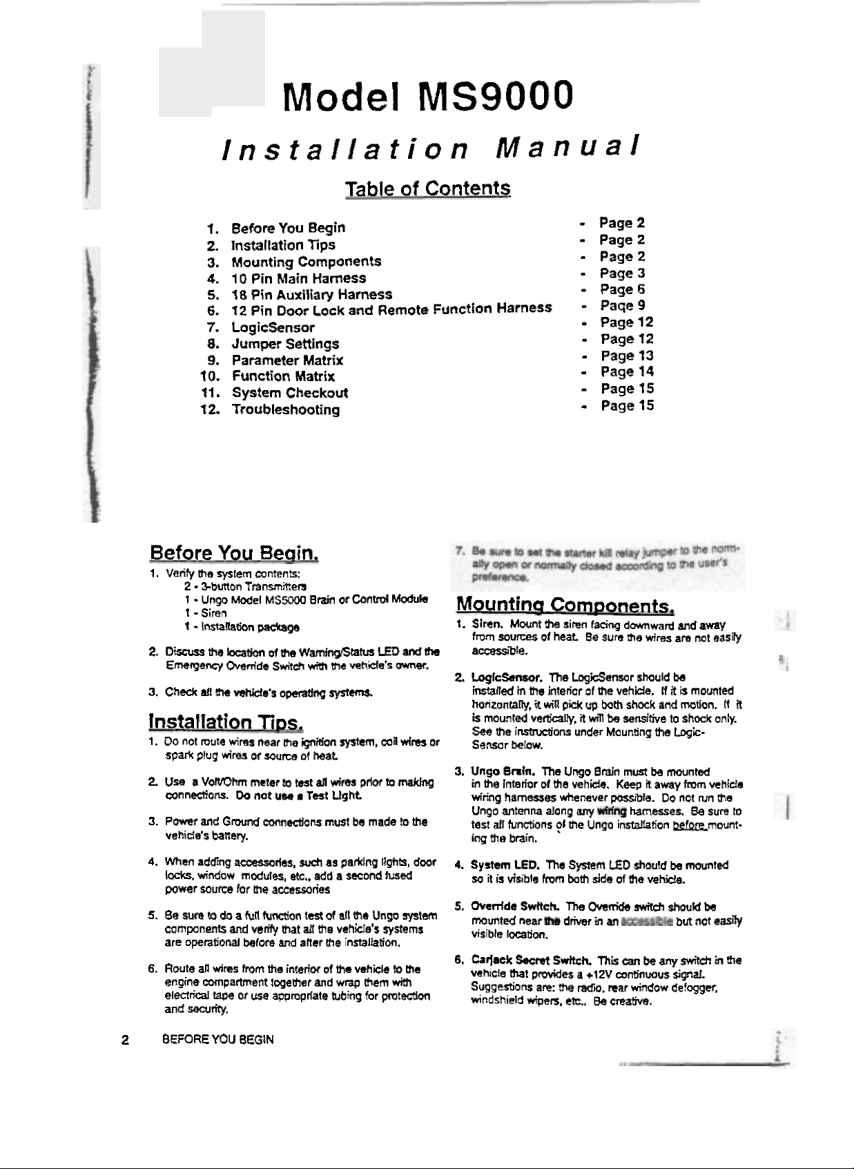
Model
MS9000
Installation
I.
Before
2.
Installation
3.
Mounting
4.
10
5.
18
6.
12
7.
Logicsensor
8.
Jumper
9.
Parameter
10. Function
11.
System
t
2.
Troubleshooting
Before
1.
Verify
2.
Discuss
Emergency
3.
Chedr
lnstallatian
1.
Do
spark
2.
Usa
connections.
3.
Power
vehide's
the
2
%burten
1
Ungo
t - Siren
1
-
Installation
the
all
tha
not
mute
plug
a
VorVOhm
and
battery.
You
system
Transmken
Model
beation
Overtide
vshide's
wiras
wires
Do
Gmd
You
Pin
Main
Pin
Auxiliarv
Pin
Door
Settings
Checkout
Beclin.
mntents:
MSW
package
d
tfw
Sdt&
opeathg
Rps,
near
Lhs
of
source
meter
tO
not
utm
connadons
Table
Begin
tips
Components
Harness
Harness
~&k
and
Matrix
Matrix
Bmin
ot
C~tltrd
WamlnfiBtm
wilh
the
vehide's
systm
@don
rystem,
of
heat
mst
all
wim
Ught
mwt
prior
be
made
a
Test
of
Remote
Module
LED
9nd
owner.
mil
drds
to
rnaCdng
!o
the
Manual
Contents
Function
ths
2
or
3,
Harness
Mountina
I.
Siren.
from
sources
accessibb.
Loglcm.
installed
hnzontab,
k
mounted
See
the
Sensdr
Unge
in
fie
wiring
Ungo
test
all
ing
tfie
Mwnt
h
of
in
the
it
win
verE-alfy,
irtsmai~m
Mow.
Bmfn.
The
Interior
of
hamesses
antenna
functions
bmin.
-
Page
2
-
Page
2
-
Page2
-
Page
3
-
Page
6
-
Page
-
-
-
-
-
-
9
Page
12
Page
12
Page
13
Page
14
Page 15
Page
15
Components.
siren
banq
Be
sum
of
me
up
bth
wii
Bmh
Ungo
domward
ms
wires
shculd
vehicle.
shoek
h
sensitive
Mounting
must
Keep
it
pwsbfe.
harnesses.
instalfation
1
and
fhe
be
away
heat
The
Logienxrr
interior
pi&
it
under
Ungo
the
vehida.
whenever
along
any
?I
the
and
am
be
it
is
mounted
motion.
to
shock
Log'c-
mounted
from
Do
not
Be
-mount-
away
not
nm
sum
easily
It
R
only.
vehide
ma
to
4.
When
adding
Ioc!ci.
power
5.
Be
sure
components
are
operational
6.
Route
engine
elearical
and
writy.
2
BEFORE
~~rles,
window
all
modules,
murm
for
me
ro
da
a
full
and
verify
belore
wims
from
mpartment
tape
or
WI
YOU
BEGIN
sueh
etc.,
accewries
Won
test
that
all
and
aher
the
interior
togeaCler
appmprlate
as
add
of
the
the
of
and
tubing
PadnCJ
a
second
aft
tho
Unw
vshiclds
installation,
the
vehicle
wmp
Fhem
for
lights,
door
SLLSPJd
sfstem
systems
to
met
wiU~
protection
4.
System
so
it
5.
Ovedds
,,#d
visible
6.
Carlack
vehtcie
Suggestions
mndsh~eId
LED.
is
visible
location.
Secret
that
The
fmm
Swftch.
near
pcwides
are:
wipes,
System
both
The
Overdo
driven
Srrttch
a
+12V
the
Mi.
ct.
ED
side
in
an
+hi
rear
Be
creative.
shourd
of
the
vehide.
switch
can
be
mnZinwus
window
be
mounted
shautd
but
any
switCh
Jgd.
de?ggw.
net
bs
,,,lty
in
the
Page 2
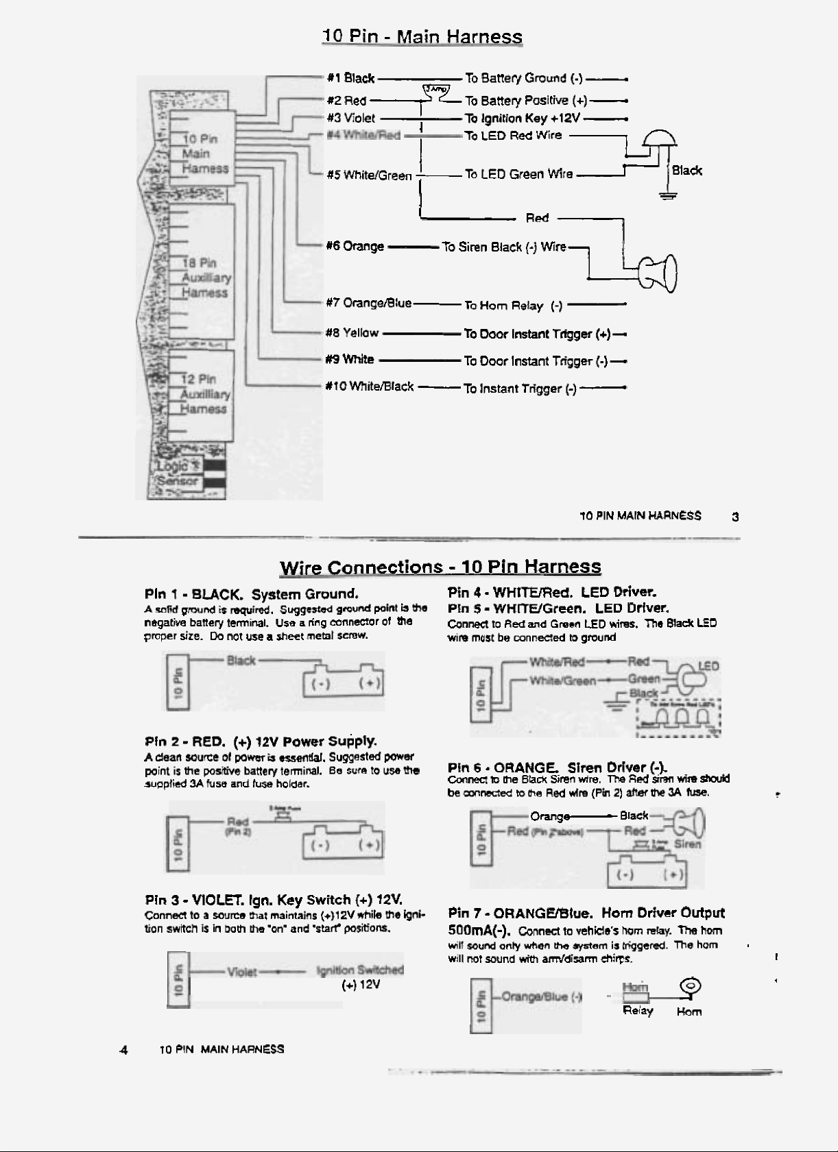
10
#l
#2
#3
Violet
Pin
lack
Red
.+p-
-
Main
Harness
I
To
Batter{
To
sane
To
Ignition
To
LED
Gmund
y
Positive
Key
Red
+12V
Wire
(-)
(+I
-
-
-
#5 White/Green
rt6
Orange
#7
OrangetBlue-
#a
yellow
#9
White
#f
O
Mite/Black
I
-To
L
To
-
LED
Siren
To
Horn
To
Door
To
Door
To
Instant
Green
Black
Relay
Instant
Instant
Wire
(-)
Wire
Rd&
(-)
Tfigger
Trigger
Trigger
L41a&
(-)
(+)
(-1
-
10
PIN
-
-
MAIN
-
d
HARNESS
3
Pln
1
k
serf
negatiw
proper
PIn
2
A
dean
point
is
supplied
Pin
3
Connen
'lion
swrtch
-
BUCK.
gmnd
banery
dze.
Da
-
RED.
wuze
the
pos~
3A
fwss
-
VIOLR.
to
a
source
is
in
System
IS
mid.
terminal.
not
we
(+)
or
power
battery
and
lgn.
mat
both
be
a
12V
b
fuse
maintains
'on"
Wire
Ground.
suggested
Use
a
ring
sheet
metal
Power
-w.
temiml.
holder.
Key
Switch
and
'skf
Connections
gmund
pint
b
thm
tmfineK3Or
screw.
supply.
Suggested
Be
(+112v
of
miu
sure
to
use
{+I
12V.
~i!a
posmom.
(+)
me
1
2v
me
thu
hni-
-
-
10
Pin
Harness
Pin
4
-
WHlfEFFlcd.
PIn
5
-
WWlTWGreen.
mnm
wim
Pin
Coonecl
befonnsctedteP'te
Pin
500mA(-).
WIT
will
to
Red
must
be
connected
6
-
ORANGE.
lo
me
Bhck
7
-
ORANGB8lue.
onb
sound
Connect
when
with
mud
no!
LED
Driver.
LED
Driver.
and
Green
LED
to
Siren
Siren
Redwlre(Ph2)afterW3A
Orang-
to
he
amddisarm
wims,
gmnd
Driver
mm,
The
Horn
vehicle's
wem
ehirs.
Red
Brack
horn
is
trigger&.
Relay
Driver
The
(-).
sren
rehy.
Bla&
wire
h.
Output
The
The horn
9
Horn
LED
SmM
r
horn
-
F
4
4
10
PIN
MAIN
HARNESS
Page 3
Pin
8
Connecl
Pin
9
Cafinecr
Pin
10
(-1.
Connect
either
of
Orange
-
YELLOW.
to
positive
-
WHITE.
to
neqative
-
WHIT
to
these
inputs
flash)
on
Door
doar
switch
Door
doof
switch
UBlaek
any
other
wZ11
shw
Tamper
AleR
Instant
Firnit.
Instant
dmit
Door
negah
as
a
Trigger
Trigger
Instant
trigger.
doar
kggrr
Trigger
A
Wgger
[+I.
(-1.
an
(rong
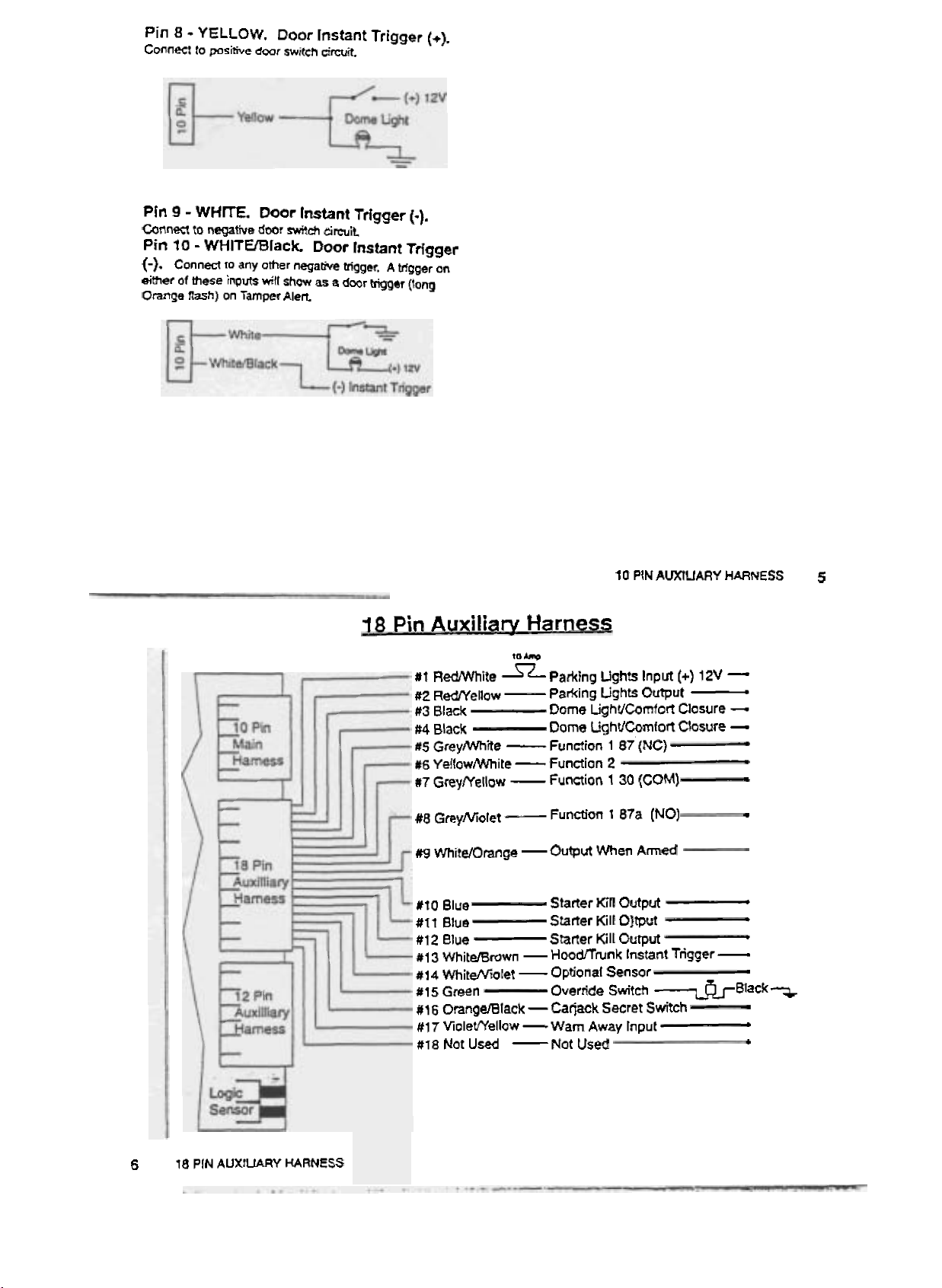
18
Pin
Auxiliary
#I
RedMlhila
#2
RMellow
s3
Black
#4
Black
#5
GreyMae
W6
YelZowWhite
117
GreySr'ellow
#8
GreyMolet
Wg
WhitelOrange
#to
Blue
#It
#12
rtl3
mitamwn
#14
White/Vl&t
#Is
Green
#16
OrangeJBlack
#I
7
#I&
Harness
to
*
=parking
-
Parking
Dome
Dome
-
Function,
-
Function
-
Function
-
Function
-0Wut
Starter
Blue
Elue
VioletfYellow - Warn
Not
Used
-
-
-
-
Starter
Starter
Hooflwnk
Qptionaf
Override
Ca
jack
Not
10
PIN
Uphts
Input
Ljghts
1
87
Output
(NC)
LighUCumf~rt
LighVCarnfort
2
1
30
(COM)
1
87a
(NO)
When
Amed
Kill
Output
Kill
OJtput
Kill
Output
Instant
Sensor
Switch
Secret
Switch
Away
Input
Used
AWUARY
(+)
12V
-
Closure
Closure
;Trigger
-
lack^
HARNESS
-
-
-
+
-
I
J
.
5
6
18
PIN
AUXtUARY
HARNESS
Page 4

Xin
1
-
Conned
Pin
2
-
REDMlhite.
to
+12V
thmugh
REDffelIow.
Wire
Park.
a
sepamte
Park
~hh
Connections
Lights
(+)I
10
Amp
Lights
2V.
hrsa.
Out.
-
18
Pin
Pin
6
-
YELLOWMThite.
500
mA
ly
disable
pafame!es
Harness
(-1.
You
the
L~icSensor
No.
2
on
may
page
select
lor
13.
Remote
this
ouZpuF
one
use
Used
with
Function
lo
automaricar-
only.
See
Frrnote
2.
System
Sun
Pins
3
and
fad
Cfos~te.
and
oaut
ararely fused
(-1
signal.
hmng
use
at
System
for
Q
Pin
5.
GREYMlhite.
(NO).
See
4
-
BLACK.
You
this
amit.
power
load
a
solid
c5assis
Panmeter
Black
-
lack
4
description
may
use
If
+12V
dirm
ground.
No.
+t
2V
Remote
under
Dame
either
is
equ~d,
from
the
a
on
or
(-)
Input
Dome
LgM
of
Comfon
Pins
7&
Parking
Circuit
PlqhtCorn-
-
wire
for
the
use
battery.
Salm
Me
page
11.
Cbsura
Functiofl
8.
Light
input
a
For
pflper
1
,87
Pin
Pin
a
On
on-board
fhe
cally
the user
alarm.
eonnnm.
YellowlWhite
QJ
-
7
-
GREYffellow.
S
-
GREYNiolet
the
MSW.
ce~ay.
H-mnk
disabled
:o
aecess
In
o~er
raymite
GrayNiolet
as
to
Remote
OQ
nut
and
@&ensor
long
fhe
operate.
Function
function
ercaed
as
the
tmnk
a
(NO)
(COM)
(NC)
18
PIN
Fundfon
1
is
20
Amps
Mggeo
vunk
remains
with&
having
bunk
fin
87
-0u2put
30
-lnpvt
87a
-Custom
AUXILIARY
Remote
Trigger
1
30
1
87a
mtmlled
on
Zhts
an:
automati-
open,
to
digarm
swrtcfi
must
(+
ar
I+
or
Appliations
HARNESS
Start
Wire
(COM).
(NC).
by
an
cirFu~C
ailowing
ma
be
-)
-)
Pin
9
-
WHITUOrange. Ground
When
tional
to
Bin
nect
Armed.
sensum.
a
radar
sensor
10 - SLUE.
to
supplied
Pins (land
3
(-1.
Connect
The
laetocy
the
wning
I
you
Jumper
mm-
closed.'
see
SO0
This
omut
onty at time
Starter
outside
12
=
BLUE.
to
outside
far
the
wish
Io
change
Semnps
diagram
Normath
HomWty
mA(-1).
ke
Ocfeat
Starter
staRer
ra
CIossd
Om.
Output
To
aaessoties
used
to
rho
sm
~ccess~des,
Additronal
1
pmvide
is
armed.
Sensor
(-),
Con-
or
abb-
power
relay*
Defeat
relayls).
kt1
crcut
a
'mrmally
an
page
-
Usn
Jvmpsn 1 and
UH~
2
is
hormalv
open'
12.
-WHI-
StVpWW1~-
2
arsd
Sun.?
w7-
and
sening.
2
3
Pin
I3
-
WHITVBrown.
Trigger
Pin
input.
Pin
Conn~
Bbck
(-1.
14
-
WHITEMolet.
Rvimr
15
-GREEN.
!a
wire
from
Rquims negative
rqaM
.
wim
Override
Override
!rum
Green
Hooflrunk
Opttonal
(.)
agpLr,
Ovemde
Switch
4-1
Ogger.
I*=
)
Switch.
SWeh.
to
g'wnd.
Sensor
Trigger
instant
From
Cunnm
rnp-
1
&
PIN
8
AUXlLlARY
HARNESS
Page 5

1
Pin
16
-
ORANGWBtack.
Switch.
vehrc!e
when advaled.
Pin
Rsuires
Pin
l3is
that
will
f
7
-
V1OLETIYelfow.
negative
18
-
Not
can
be
provide
(-1
input
Used,
Carjack
conneed
+12V
mnlinwusly
Warn
to
pmuce
to
any
switch
Away
a
warn
Secret
{not
pulsed)
away
in
the
Input.
c?lirp.
Wire
Connections
Pin
1
-
GREENMolet.
Pin
2
-
GREENIY~IIow.
Pin
3
-
GREENMchite.
Pin
4
-
BL'UWiolet.
Pin
5 - SLUUYellow.
Pin
6
-
BLUWhite.
sure
to
see
proper
System
selections
make
Door
Door
Ooor
Door
Parameters
lor
use
-
12
Door
Ooor
Unlock
Unlock
Unlock
1.3,s
mlh
Pin
Harness
Lock
Lack
Lock
and
5
automatic
07a
30
(COM)
87
(NO)
87a
30
87
(NO)&
on
pase
docr
(UC)
(NC)
(COME
13
to
lccko.
-
I2
---*---
Pin
Poor
Lack
and
Remote
#I
GreemVoiet
#2
GreenlYelIow
U3
GreeniWhite
#5
Blueffellow
318
YellowMolet
12
Function
Door
Door
Door
Ooorlrnk
Doorlock
6wdock
Function
Function
Function
PIN
AUXILIARY
Harness
Unlock
Unlock
UnZock
87a
30
87
3
4
5
87a
30
87
(NO)
(NCJ
(COM)
(NO)
HARNESS
(NC)
(COM)
9
b
!
i
i
1
#I
1
Yelow/Red
1812
YellowJOmnge
12
PIN
t
0
AUXIUAFW
HARNESS
Function
Function
6
7
(latchedNnlatched)
.#
Page 6

Pin
Pin
Pin
Pin
Pin
An
me
7.
Not
Used.
8
-
YELLOWMolet.
9
-
YELLOWIBlaek.
TO
-
YELLOVUBlue.
f
I
-
YELLOWmed.
above
are
500
mA
Function
(-)
outputs.
Function
Function
Function
3.
4.
5.
6
RYelloW?
Pin
12
-
YELZOWlOrange.
tatehed
System
Or
Parameter
Un
late
8
on
hed.
page
t2
Remole
500
13
for
PIN
AUXIUARY
Functions
Function
m~
(-) uutpvt
pmgramming.
HARNESS
7.
Eh
t
1
LocaicSensor
The
LwicSen~r
Ing
surface.
me
fire
waR.
For
seruihiry
LegicSmsor
Far
sensiw
Pbg
the
Vogo
brain.
Typid
to
horircntally
to
Unp
must
I-tiions
both
sb&
shock
Logemxlr
h
onty
are
and
mount
into
hstd
the
steering
motLon.
Zhe
h
RCA
mount
sensor
to
MUM.
almn
the
vsrticav.
the
Of
Page 7

Programming
t.
Ooor
Locks
Only
2.
LwlcSensor
ed
3.
Ign.
Controlled
4.
System
5.
Dome
6.
Passive
7.
Dwr
8.
Latched
To
Change
1.
lgniZion
2.
Mmn
3.
Press
The
4.
Press
To
Reset
1.
Ignition
2.
Press
3.
While
Off
Door
Diaqnostks
LightfComton
Arming
kk
Occrr
Ziming
Function
Parameters:
on.
4
seconds,
button
1
or
System
buaon
1
LED
to
Allparameters
off.
€ha
MOde
holding
button
bunon
Cocks
Chum
Lucks
7
use
Mode
2
la
will
mange
3.
select
shw
Zha
3
dmss
turn
Matrix
Transmitter
Mode
None
Grrwn
Green
Green
O~W
Orange
Red
Red
button
punon
tha
desired parameter.
cumfit
xtling.
sem'ng.
to
and
hdd
Lhe
ignitlon
on.
for
Ungo
Parameters
Button
f
or 2
(mt
d~~sarm)
1
2
1
and
2
I
2
I
hold
lor
4
-1
2
3)
to decl
Sofa
Factory
on
the
All
(See
=
factory
thid
push.
settings
desired
maub
Settings:
am
Pro
LED
Solid (Fadorl)
1300rs
LugicSensor
Door
will
Wll
no1 Ignore
Dcme
OOUE
I
mnd
Nd
latched
color.
above).
selrting.
Urithin
5
reset
tieconds,
m
rmw
Security
will
not
not defeated
not
lock
Cight
w~ll
net
pulse
d~
factory
lock
dome
light
Imk
msmitter
settings.
Systems
LED
Flashing
LqicS-r
Doors
win
Will
ignow
C3rnren
DWS
win
4
second
LED
flash
defeat-
w
dome
Closure
lock
pulse
d.
light
Function
Function
Function
Function
Funchon 4
Fum'on
Funaon
Fundtian
1
2
3
5
5
7
Matrix
Nan@
Gt#n
Green
orange
Orange
Red
Red
for
Ungo
1
or
2
(Not
AmrtObzarm)
1
2
1
2
1
2
Pro
Onhard
Security
lmnk
Remote
Selectable
relay
release
start
wirtr
latched
on
MSm.
an
all
selecable
or
unlat-
Syseerns
Smaff
models.
LqicSenrot
Umut
shunt
-
MSm
14
FUNCTION
MATRIX
Page 8

!
I
I
I
Svstem
1.
Check
all
-LogicSensor
-Doors
-TnmWlood
-Additional
2.
Verity
starler
the
vehicle
3.
Antl-Cajack
a.
Change
press
b.
In
Level
sending
c.
In
revel
seconds
Trouble
1.
Unga
system
a.
Check
b.
Ann-Caqadr
c.
Transminer
2
Cannot
enter
a.
lgnition
b.
Icyition
c.
Tranwnrner
d.
Check
e.
An3-Ca
Checkout
trigger
sources.
(if
connected)
sensors
kin
is
property
when
Me
sys:em
(if
connected).
mDdes
-
Me
II.
the
I.
hrm
AmrlDisarm
trip
system
reset
slgnal.
trip
Me
system
after
Me
turning
Shootinq
does
Transmmer
not
on
Transminer
jack
not
battery
is
mpp&
not
in~halired
Parameter
on
br
mom
not
initialized
banery
is
trpped
connected
Verify
on
the
bunon.
by
by
respond
rdjudng
Man
4
has
been
that
secret
StaBng the
opening
me
ignition
to
the transmitter.
mods
secgnds
by
trying
triggered.
you
can:
switch
vehicle
the
door
on.
to
and
winlout
40
start
3.
lgnitlon
a.
Venty
doar
b.
Mr
c.
Door
4.
LogkSonsor
a.
Venfy
is
not
5.
Anti-Carjack
a.
Anti-Carjack
b.
Door
E.
System
6.
Antf-Cadack
a.
Reset
b.
Reset
c.
In
the
switded
signal
8.
It
mre
system
controlled
system
panmmter
locks
was
opened
locks
nut
ccnnectw
not
the
!he
ofl
wilt
mode
/use
will
sw~tch
sw~tch
trigger
off,
can
be
inconem
m'll
Ignore
wr(tlnq
Sensitwrw
posrlion
not
if
not
mf
not
then
sent
that
in
plnswitch
full
door
lecu
after
ignition
Mp.
is
SM
ladty.
mt
receiving
pressM
mode,
the
back
on
reset
signals
further
not
is
set
lo
Ungc
setting
b
off
+l2Vob
3
times
ignition
agaln
are
reset
worktng
for
icnition
was
turned
Syslern
for
the
wrthin
must
before
sent.
signal
antmfie
on
h@i-
1Q
*ecwrds
be
me
the
Unga
lor
2
minutes
!
t
reset
SYSTEM
CHECKOUT
t
5
 Loading...