

Page 1

VARIANT 260
VARIANT 260 ROTO CUT
VARIANT 280
VARIANT 280 ROTO CUT
Operating
instructions
Page 2

e
s
ve
r
s
f
a
ty
e
eg
r
l
u
t
a
o
i
!
s
n
e
R
d
a
a
d
n
o
b
Page 3

1
Introduction
Page 4

Page 5

Introduction
Introduction
INTRODUCTION
These operating instructions for round balers
VARIANT 260/260 RC and VARIANT 280/280 RC
(valid from 73000005; 73200011) were primarily
written for the machine operator and inform about use,
adjustment and operation of the round baler.
Please follow the guidelines on correct care and
maintenance of your round baler to ensure permanent
availability and a long service life of the round baler.
Have your round baler inspected by your CLAAS
service center immediately after harvest within the
framework of these winter storage recommendations.
Deficiencies in maintenance or incorrect operation
lead to a drop in performance and result in time losses.
Use our experience and latest knowledge in long stalk
harvest implemented in this round baler by correct
operation and thorough maintenance, and your round
baler will always produce excellent results.
Your CLAAS Service Department
000 298 456 6 - BA VARIANT 260/280 - 260/280 RC 1.1.1
Page 6

Introduction
1.1.2 BA VARIANT 260/280 - 260/280 RC - 000 298 456 6
Page 7

2
Contents
Page 8

Page 9

Contents
CONTENTS
Contents
1. Introduction
Introduction ............................................................................ 1.1.1
2. Contents
3. General notes
Road traffic ............................................................................ 3.1.1
To be observed especially ..................................................... 3.2.1
Type plate ........................................................................ 3.3.1
Machine serial number .................................................... 3.3.1
4. Safety precautions
Safety precautions ................................................................. 4.1.1
Personal injury may result if these safety precautions
are not followed ............................................................... 4.1.1
Safety signs ..................................................................... 4.1.3
Transporting baler on a public thoroughfare .................... 4.1.3
Transporting baler on a public thoroughfare .......................... 4.1.5
Recommended warning lights ......................................... 4.1.5
Preparing for transport ..................................................... 4.1.5
4.
4. Safety signs
5. Technical data
CLAAS Variant 260/280 / Variant260/280 RC ...................... 5.1.1
Intake elements ............................................................... 5.1.1
Cutting device .................................................................. 5.1.1
Bale compression ............................................................ 5.1.2
Wrapping facility .............................................................. 5.1.2
Wheels ............................................................................. 5.1.2
Hydraulics ........................................................................ 5.1.2
Required tractor hydraulics .............................................. 5.1.3
Hydraulic pressure ........................................................... 5.1.3
Electrics ........................................................................... 5.1.3
CLAAS Variant 260/280 / Variant260/280 RC ...................... 5.1.4
Dimensions of the round baler ......................................... 5.1.4
CLAAS Variant 260/280 / Variant260/280 Roto Cut ............. 5.1.5
Safety installations ................................................................. 5.1.5
Shearing screws .............................................................. 5.1.5
Overload clutch ................................................................ 5.1.5
6. Design and working principle
Machine overview .................................................................. 6.1.1
Power train ...................................................................... 6.1.3
Shear coupling and freewheeling propshaft .................... 6.1.3
Cam clutch – propshaft .................................................... 6.1.3
Pick up ............................................................................. 6.1.4
Cutter ............................................................................... 6.1.5
Dummy blade holder (optional) ....................................... 6.1.5
Baling chamber ................................................................ 6.1.6
Wrapping of bales ............................................................ 6.1.6
Bale ejector ...................................................................... 6.1.7
Storage of round bales .................................................... 6.1.7
Rotor shut down clutch .................................................... 6.1.7
Manual reversing of rotor ................................................. 6.1.8
Twine boxes .................................................................... 6.1.8
Steps ............................................................................... 6.1.9
Fire extinguisher (country option) .................................... 6.1.9
Active hydraulic system ................................................... 6.1.9
Automatic chain lubrication ........................................... 6.1.10
Side indicator (optional) ................................................ 6.1.11
Control box .................................................................... 6.1.11
7. Before starting operation
Check and pay attention to the following before
starting operation of the machine .......................................... 7.1.1
Hitching up the baler ............................................................. 7.2.1
Coupling the propshaft to the baler ................................. 7.2.1
Propshaft with clamping cone lock .................................. 7.2.2
Installing propshaft with CC-lock ..................................... 7.2.2
Parking support ............................................................... 7.2.2
Before coupling the round baler ...................................... 7.2.3
After coupling the round baler ......................................... 7.2.3
Coupling to the trailer coupling ring ................................. 7.2.3
Greasing the towing eye ................................................. 7.2.4
Connecting the propshaft to the tractor
(for trailer coupling) ........................................ 7.2.4
Shortening the propshaft ................................................. 7.2.6
Preventing the propshaft guards from rotating
with the drive shaft .......................................................... 7.2.7
Coupling to the towing hitch ............................................ 7.2.8
Connecting the propshaft to the tractor ........................... 7.2.9
Attaching to the ball head .............................................. 7.2.10
Connecting the cables ........................................................... 7.3.1
Control box ...................................................................... 7.3.1
Power supply ................................................................... 7.3.1
Travel lights ..................................................................... 7.3.1
Connecting hydraulic hoses ............................................ 7.3.2
Tailgate opening speed ................................................... 7.3.2
Before transport ..................................................................... 7.4.1
8. Setting up the baler
Collecting ............................................................................... 8.1.1
Height adjustment of pick-up ........................................... 8.1.1
Adjusting pick-up working height
(Pick-up without support wheels) .................................... 8.1.1
Pick-up with support wheels ............................................ 8.1.2
Support wheels ............................................................... 8.1.2
Cutting device
(VARIANT 260/280 RC) ........................................................ 8.2.1
Dummy knives ................................................................. 8.2.1
Installing and removing knives ........................................ 8.2.1
Placing the blades into the dummy blade holder ............ 8.2.2
Locking the knives ........................................................... 8.2.3
Pressing bales ....................................................................... 8.3.1
Baling pressure adjustment ............................................. 8.3.1
Adjusting the bale diameter ............................................. 8.3.1
Adjusting the soft core diameter ...................................... 8.3.2
Wrapping ............................................................................... 8.4.1
Net wrapping ................................................................... 8.4.1
Inserting the net .............................................................. 8.4.1
Adjusting the number of net windings ............................. 8.4.5
000 298 456 6 - BA VARIANT 260/280 - 260/280 RC 2.1.1
Page 10

Contents
Twine wrapping ................................................................ 8.4.6
Threading the wrapping twine .......................................... 8.4.6
Adjusting number of twine windings .............................. 8.4.10
Adjusting the twine windings at the outer edges
of the bale ...................................................................... 8.4.11
Tying with three threads ................................................ 8.4.12
Preparing the twine eyelet ............................................. 8.4.12
Tying with three threads ................................................ 8.4.12
Baler adjustment under extreme silage conditions ................ 8.5.1
Removal of belt guides .................................................... 8.5.1
Installation of belt guides ................................................. 8.5.1
Round baler with twine and net wrapping .............................. 8.6.1
Changing to twine wrapping ............................................ 8.6.1
Adjusting drive for twine wrapping ................................... 8.6.1
Applying the V-belt brake ................................................. 8.6.1
Changing to net wrapping ................................................ 8.6.2
Adjusting drive for net wrapping ...................................... 8.6.2
Releasing V-belt brake .................................................... 8.6.2
Baling of silage ................................................................ 8.6.2
Installing dummy knife holder (optional) on
VARIANT ROTO CUT ..................................................... 8.6.3
9. Operation
Starting operation of round baler ........................................... 9.1.1
Charging the baling chamber ........................................... 9.1.2
Side indicator ................................................................... 9.1.3
Automatic wrapping ......................................................... 9.1.4
Tying delay ...................................................................... 9.1.4
Delay function .................................................................. 9.1.4
Twine wrapping: Setting the delay ................................... 9.1.4
Net wrapping: Setting the delay ....................................... 9.1.5
Wrapping and ejection of bales ....................................... 9.1.6
Placement of bales .......................................................... 9.1.8
Output of bales without bale ejector ................................ 9.1.8
Bale counter ..................................................................... 9.1.8
Round baler with net wrapping ........................................ 9.1.8
Round baler with twine and net wrapping ........................ 9.1.8
Round baler with twine wrapping ..................................... 9.1.8
Manual overload of automatic wrapping .......................... 9.1.9
Triggering early wrapping ................................................ 9.1.9
Delaying the wrapping process: ....................................... 9.1.9
Cutting device (ROTO CUT) .......................................... 9.1.10
Slewing the blades in ..................................................... 9.1.10
Slewing the blades out ................................................... 9.1.10
Adjusting the volume of the audible warning signal ....... 9.1.10
Blockage of the round baler ................................................... 9.2.1
Cam clutch – propeller shaft ............................................ 9.2.1
Rotor reversing facility
(VARIANT 260/280 / 260/280 RC) ................................... 9.2.1
Fault, cause or remedy .......................................................... 9.3.1
Twine wrapping ................................................................ 9.3.1
Net wrapping .................................................................... 9.3.2
10. After use
Unhitching the baler ............................................................. 10.1.1
Wheel chock .................................................................. 10.1.1
Parking support .............................................................. 10.1.1
Control box .................................................................... 10.1.2
Hydraulic hoses and electrical wiring ............................. 10.1.2
Propshaft ....................................................................... 10.1.3
Gauge wheels ............................................................... 10.1.4
Cleaning of dirt .............................................................. 10.1.4
11. Maintenance
Important notes on maintenance ......................................... 11.1.1
General notes on maintenance ..................................... 11.1.1
Maintenance and lubricant tables ........................................ 11.2.1
Maintenance tables ....................................................... 11.2.1
Lubricant table ............................................................... 11.2.2
Drives .................................................................................. 11.3.1
Shear pin main drive ..................................................... 11.3.1
Shear pin pick-up drive .................................................. 11.3.1
Mitre gear ...................................................................... 11.3.1
Tightening the drive chains ........................................... 11.3.2
Tightening the pick-up drive chain ................................. 11.3.2
Tensioning the drive chain for the feed auger ............... 11.3.3
Adjusting the pressure springs for the pressing roller ... 11.3.3
Adjusting the clamping device for the net blade ............ 11.3.4
Adjusting the disc brake ................................................ 11.3.4
Tightening the chain drive tension springs
(belts and rotor) ............................................................. 11.3.4
Tightening the chain drive tension springs
in the tailgate ................................................................. 11.3.5
Adjusting the tension springs for top tensioning arm ..... 11.3.5
Adjusting the tension springs for bottom tensioning arm 11.3.5
Tightening the tension spring for the net roll brake bow 11.3.6
Adjusting the spring cylinder for freewheeling drive ...... 11.3.6
Adjusting the bale ejector tension springs ..................... 11.3.6
Adjusting the linkage to the bale ejector limit switch ..... 11.3.7
Drive brake for twine wrapping ...................................... 11.3.7
Adjusting the pressure springs on shut-off coupling ...... 11.3.7
Adjusting the friction clutch pressure springs
(ratchet wheel) (Net wrapping) ...................................... 11.3.7
Adjusting the twine tensioner ........................................ 11.3.8
Settings of the inductive sensors ................................... 11.3.8
Inductive sensor „maximum ball diameter“ .................... 11.3.8
Inductive sensor „closed door“ ...................................... 11.3.8
Hydraulic oil filter
(Machines with filter system) ......................................... 11.3.9
Automatic chain lubrication ......................................... 11.3.10
Adjusting the Linatex guide plate ................................ 11.3.11
Fire extinguisher (optional) .......................................... 11.3.12
Flat belts .............................................................................. 11.4.1
Relieving flat belts ......................................................... 11.4.2
Checking flat belts ......................................................... 11.4.3
Relieving flat belts ......................................................... 11.4.4
Installing flat belts .......................................................... 11.4.6
Belt alignment ................................................................ 11.4.7
Adjusting the scraper, bottom roller ............................... 11.4.7
Tires .............................................................................. 11.4.8
Check tight fit of wheel nuts .......................................... 11.4.8
Checking wheel hub backlash ....................................... 11.4.8
Adjusting the backlash .................................................. 11.4.8
2.1.2 BA VARIANT 260/280 - 260/280 RC - 000 298 456 6
Page 11

Proposals for winter storage ................................................ 11.5.1
12. Lubrication chart
Lubricants and notes ........................................................... 12.1.1
13. Glossary
Contents
000 298 456 6 - BA VARIANT 260/280 - 260/280 RC 2.1.3
Page 12

Contents
2.1.4 BA VARIANT 260/280 - 260/280 RC - 000 298 456 6
Page 13

3
General notes
Page 14

Page 15

General notes
General notes
ROAD TRAFFIC
The vehicle operator must always have two wheel
chocks on the vehicle.
When driving on public roads with agricultural or
forestry equipment attached, the highway code of
the respective country must be strictly complied
with.
Above all, no bale must be in the round baler.
If parts of the baler, the conditions of which are
clearly specified, are later changed or modified in
such a way that their operation will endanger any
other participants in traffic, the type approval will
become invalid and a new type approval must be
applied for. In this case the Iof working equipment
must be presented to the responsible technical
inspection authority for motor vehicles (e.g. TÜV) for
issuing an expertise (§ 19 para. 2 StVZO).
If you are in doubt that this may be the case, please
contact us as the manufacturer.
If the round baler is pulled after a tractor, especially
the following devices have to be connected:
- The cable of the lighting equipment.
- The cable for power supply.
Before starting to drive the condition of:
- the connection between pulling vehicle and baler
- the lighting equipment must be checked.
If the license plate given to the vehicle owner for
one his tractors is concealed when the baler is
hitched up, attach a picture of this plate, including its
lighting, onto the baler.
The local road traffic regulations may differ in
individual countries.
The maximum speed under the road traffic
regulations for the country of operation must be
observed. However, the hitched baler is designed to
travel at a maximum speed of 25 km/h (16 mph). It
is not permissible to exceed that speed.
000 298 456 6 - BA VARIANT 260/280 - 260/280 RC 3.1.1
Page 16

General notes
3.1.2 BA VARIANT 260/280 - 260/280 RC - 000 298 456 6
Page 17

General notes
General notes
TO BE OBSERVED ESPECIALLY
In order to avoid any dangers all information in
these operating instructions must be read and
applied by all persons using, maintaining,
repairing or inspecting this round baler. Read in
particular the section “Concerning safety”.
The use of spare parts, accessories and
attachments not originally supplied by CLAAS
and not tested and approved by CLAAS may
impair design specific characteristics of CLAAS
machines or have a negative effect on their
functionality, thereby impairing the active and/
or passive driving as well as the working safety.
CLAAS does not assume liability for damage
resulting from the use of parts, accessories and
attachments not originally manufactured and
supplied by CLAAS.
Technical data, dimensions and weights are
non-binding. The right for changes in the course
of technical development and errors remains
reserved.
The terms front, rear, right and left always apply
in travel direction.
000 298 456 6 - BA VARIANT 260/280 - 260/280 RC 3.2.1
Page 18

General notes
3.2.2 BA VARIANT 260/280 - 260/280 RC - 000 298 456 6
Page 19
General notes
General notes
When ordering spare parts or if you have any technical
questions please provide the machine number of the
round baler together with the respective serial number.
This is absolutely necessary in order to avoid wrong
spare parts deliveries.
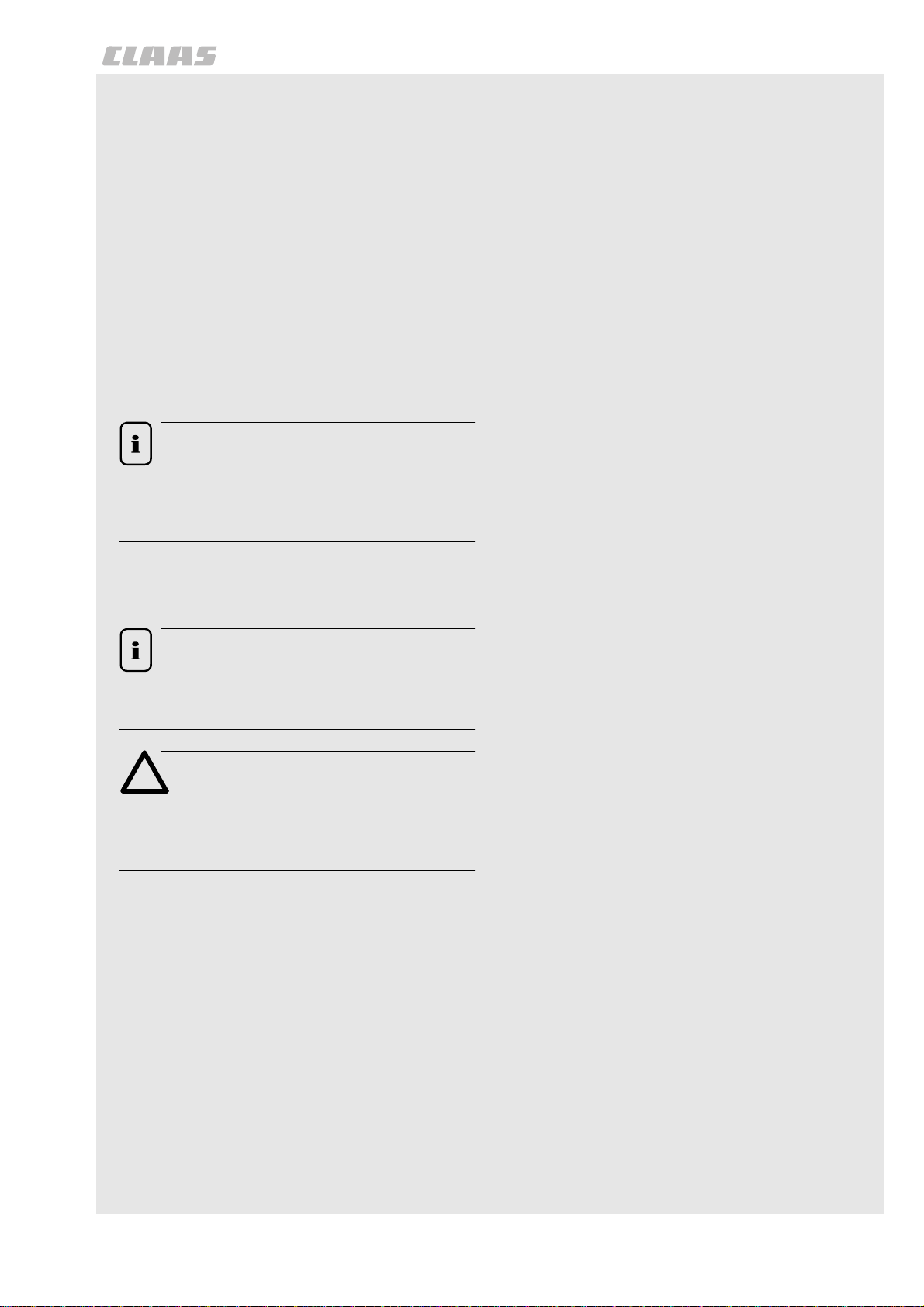
Type pl ate
The type plate with the machine serial number is fixed
to the right hand machine wall.
A=Type
B = Year of construction
C = Machine number
D = Permissible total weight
(Fig. 1, 2)
1
Type:
N°
Année de Fabrication
Poids total autorisé en charge
USINES CLAAS - FRANCE
57148 - WOIPPY
800093
A C
B
D
2
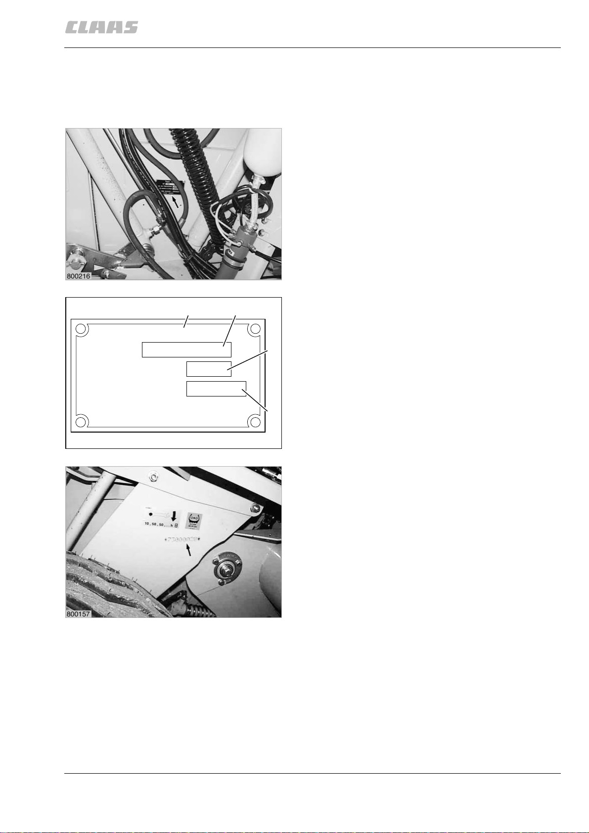
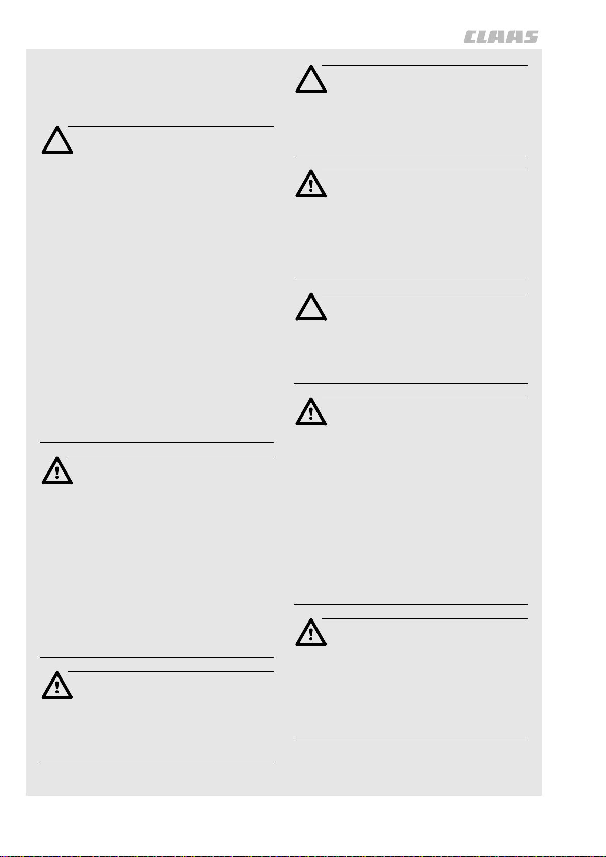
Machine serial number
The machine number is additionally stamped in the
tie-bar above the right-hand wheel.
(Fig. 3)
3
000 298 456 6 - BA VARIANT 260/280 - 260/280 RC 3.3.1
Page 20

General notes
3.3.2 BA VARIANT 260/280 - 260/280 RC - 000 298 456 6
Page 21

4
Safety precautions
Page 22

Page 23
Safety precautions
Safety precautions
SAFETY PRECAUTIONS
For your safety, and those working with you, follow
these safety precautions and observe all safety
signs on the machine.
In order to provide a better view, certain
photographs or illustrations in this manual may
show an assembly with the safety shield removed.
However, a machine should never be operated in
this condition. Keep all shields in place. If shield
removal becomes necessary for repairs, replace
shield prior to machine operation!
Replace any Danger, Warning, Caution or
Instruction Safety signs that are missing or not
readable. Location of safety signs are indicated
within this manual.
Note!
The figure in () refers to the adjacent picture
and indicates the correct location of the
safety sign on the machine.
Personal inj ury ma y result if these safety precautions are not followed
• MAKE SURE no person is allowed on any part
of the Baler when tractor is running.
• MAKE SURE all safety shields and covers are
installed properly when Baler is operating.
• MAKE SURE all bystanders are in a safe
position before starting the tractor or operating
Baler.
• MAKE SURE the pickup head is fully lowered
before any part of the hydraulic system is
disconnected.
• MAKE SURE no one is allowed under the
pickup head unless the pickup head is in
transport position and securely locked.
• MAKE SURE all safety shields on Baler are in
place and secured when any have been
removed for servicing, to make adjustments,
etc. Remember, these shields are provided for
the protection of those working on or around
the Baler.
When parts are replaced that have safety signs,
make sure you install a new safety sign with each
new part.
Note!
New safety signs are available from your
CLAAS Dealer.
Attention!
Before using the machine read and
understand Operator’s Manual safety
messages!
Read and understand all safety signs on the
machine.
Learn and practice safe use of controls before
operating.
It is your responsibility to understand and follow
manufacturers instructions on machine operation,
service, and to observe pertinent laws and
regulations.
Operator Manuals may be obtained from your
CLAAS Dealer.
• NEVER STAND in path of Baler while
operating.
• KEEP OUT of Baler compartment while
operating.
• BE SURE all hydraulic fittings are tightened
securely whenever they have been loosened or
disconnected. Replace all hoses which have
become frayed. Escaping hydraulic oil under
pressure can cause personal injury.
• If Baler hydraulic system is equipped with an
accumulator, accumulator shutoff valve must be
closed before: (a) any part of the hydraulic
system is loosened or is to be disconnected,
and (b) the Baler is to be transported for any
distance.
• T AKE NO TE that hydraulic fluid under pressure
escaping from a very small hole can be almost
invisible. Use a small piece of cardboard or
wood to search/check for possible leaks.
• NEVER use your hands to detect pressure
leaks.
• CONSULT A DOCTOR immediately if you
sustain an injury by escaping fluids. Serious
infection or reactions can develop if proper
medical treatment is not administered quickly.
• MAKE SURE all oil or grease is removed from
operator’s ladder and platform and other
access areas immediately if any is spilled.
000 298 456 6 - BA VARIANT 260/280 - 260/280 RC 4.1.1
Page 24
Safety precautions
• BE EXTRA CAREFUL to keep hands, feet and
loose clothing away from moving parts.
• READ THIS MANUAL and take note of ALL
safety precautions included herein.
Attention!
Do not remove, install or make repairs to a
tire on a rim. Take tire and rim to the
nearest available tire specialist, who have
experience and the safety tools. If the tire
is not correctly positioned on the rim, or
the tire pressure is too high then the tire
bead is liable to loosen on one side,
resulting in the pressured air to leak out at
high speed and with force. This can lead
to the risk of the tire flying off and causing
serious injury!
Attention!
To provide more secure hand and foot
mobility, preventing slipping and possible
injury, always face the machine when
mounting and dismounting.
Danger!
Never operate the engine in a closed
building. Proper ventilation is required
under all circumstances.
Contact with belts, chains etc. can cause
injury. Keep clear.
A tire can explode during inflation and
cause serious injury or death. Never
increase air pressure beyond 35 PSI to
seat the bead on the rim. Replace a tire if
it has a defect. Replace a wheel rim which
has cracks, wear or severe rust. Make
sure that all the air is removed from a tire
before removing the tire from the rim.
Never use force on an inflated or partially
inflated tire. Make sure the tire is correctly
seated before inflating.
Danger!
Check the machine for leaks or any parts
that are broken, not working correctly, or
missing. Before you start the machine,
tighten all caps, dipsticks, battery covers,
etc.
Never use gasoline, naphtha or any other
volatile material for any cleaning
purposes. These materials may be toxic
and/or flammable.
Attention!
To help prevent personal injuries during
operation and maintenance, loose shirts,
sleeves or jackets must never be worn by
the operator.
Danger!
Before starting the tractor, be sure all
operating controls are in neutral. This will
ease starting loads on the starter and
batteries of the tractor and will eliminate
the accidental start up of power driven
equipment.
Travel speed should be such that
complete control and machine stability is
maintained at all times. Where possible,
avoid operating near ditches,
embankments and holes. Reduce speed
when turning, crossing slopes, and on
rough, slick, or muddy surfaces.
Use only metric tools. Other tools may not
fit properly. They may slip and cause
injury.
Danger!
Before leaving the tractor, stop the engine,
and remove the starter key. The gear shift
lever must be in neutral and the parking
brake engaged.
4.1.2 BA VARIANT 260/280 - 260/280 RC - 000 298 456 6
Danger!
On highways use lighting equipment
according to local laws. Keep SMV
emblem clean and visible. Replace SMV
emblem when damaged or sun faded.
Stop, look and listen before entering
public thoroughfare or a highway.
Page 25
Attention!
Safety precautions
Safety signs
Collision of high speed road traffic and
slow moving machines can cause
personal injury or death.
Stay off slopes too steep for safe
operation. Shift down before you start up
or down a hill with heavy load. Avoid ”free
wheeling”.
Danger!
Provide a first aid kit for use in case of
accident.
As a safety precaution, it is suggested one or
more fire extinguishers be carried on the Baler
at all times. Fire extinguishers must be
purchased from Fire & Safety equipment supply
store.
Attention!
Look for this symbol to point out important
safety precautions. It means BECOME
ALERT! YOUR SAFETY IS INVOLVED.
This machine is of metric design.
Measurements in this manual are metric
with the customary U.S. measurements
following. Use only metric hardware and
tools as specified.
Attention!
Install new safety signs if the old safety
signs are destroyed, lost, painted over or
can not be read. When parts are replaced
that have safety signs, make sure you
install a new safety sign with each new
part.
Note!
New safety signs are available from your
Dealer or write to:
CLAAS OF AMERICA Inc.
P.O.Box 3008
3030 Norcross Drive
Columbus Indiana 47201
USA.
Transporting baler on a public thoroughfare
Whenever a Baler is to be transported on a public
thoroughfare, the following preparation of the Baler
should be made:
• Position pickup in the transport position. Close
gate, raise pickup and converging wheels, if
equipped.
• Make sure warning devices, such as slow
moving vehicle emblem, reflectors, etc., are
installed, clean and are in good condition.
Replacement Parts:
– When replacement parts are necessary for
periodic maintenance and servicing, genuine
CLAAS replacements must be used to restore
your equipment to original specifications.
– CLAAS will not claim responsibility for usage of
unapproved parts and/or accessories and
damages as a result of their usage.
• Use flashinglights according to local laws. Keep
SMV emblem clean and visible. Replace SMV
emblem when damaged or sun faded.
• For reference purposes, measure the overall
width and height of the Baler. These
measurements are particularly important for
transporting along narrow roads and where
underpasses may be encountered.
• If the Baler hydraulic system is equipped with
an accumulator, make sure the accumulator
shutoff valve is closed.
000 298 456 6 - BA VARIANT 260/280 - 260/280 RC 4.1.3
Page 26

Safety precautions
Danger!
Proper tire pressure should be maintained
at all times to insure stability during road
travel.
Always use a safety chain while
transporting baler. Sudden jolts or rocking
could cause the drawbar to break. If a
rocking motion occurs when transporting,
reduce speed until rocking stops. Check
rear tractor wheels for any tire tread wear
or pressure loss. Refer to operator’s
manual for tractor tire pressures.
Use care when towing baler at transport
speeds. Reduce speed if the weight of
baler exceeds weight of tractor.
When towing baler on public roads, an
extended mirror to improve visibility of
traffic behind the baler is recommended.
Mirrors are available from your dealer.
When the Baler is being transported on a public
thouroughfare, the following precautions must be
observed:
• Reduce speed before applying the brakes.
Using a hydrostatic transmission to slow the
vehicle is more effective than merely applying
the brakes.
If in doubt regarding local or state/provincial laws
pertaining to transportation of farm equipment,
consult your local law enforcement agency.
Danger!
Use or warning lights and turn signals are
recommended when transporting this
equipment on public roads, unless
prohibited by state or Local Laws.
A safety lighting kit is available from your
CLAAS dealer.
☞ Always use a safety chain when
transporting baler on public roads.
Transporting baler at speeds in excess
of 20 mph (32 km/h) is not
recommended.
Use care when towing baler at transport
speeds. Reduce speed if the combined
weight of baler with bale exceeds weight
of tractor. The approved minimal total
weight of tractor must not receed 2.5 tons
(2500 kg).
The towed baler can be transported
without brakesystem, when the approved
minimal total weight of tractor is 2.5 tons
(2500 kg).
Note!
Install new safety signs if the old are
destroyed, lost, painted over or can not be
read. When parts are replaced that have
safety signs, make sure you install a new
safety sign with each new part.
New safety signs are available from your
Dealer or write to:
CLAAS OF AMERICA Inc.
P.O. Box 3008
3030 Norcross Drive
Columbus Indiana 47201
USA
TO SHOW TECHNICAL DETAILS OF BALER
COMPONENTS AND ASSEMBLIES IN THIS
OPERATOR’S MANUAL, A NUMBER OF SAFETY
SHIELDS AND PANELS WERE REMOVED FOR
PHOTOGRAPHIC PURPOSES O NLY. ALL
SAFETY SHIELDS AND PANELS MUST BE
INSTALLED BEFORE BALING OPERATIONS
COMMENCE.
4.1.4 BA VARIANT 260/280 - 260/280 RC - 000 298 456 6
Page 27

Safety precautions
Safety precautions
TRANSPORTING BALER ON A PUBLIC THOROUGHFARE
Attention!
When transporting the baler on a highway
use SMV emblem (PN 514 155.1).
Recommended warning lights
1
Attention!
Use of flashing warning lights and turn
signals are recommended when towing this
equipment on public roadfs unless prohibited
by state or local regulations. An implement
safety lighting kit is available from your
Dealer.
800297
Preparing for transport
Attention!
Always use a safety chain while transporting
baler. Sudden jolts or rocking could cause
the drawbar to break. If a rocking motion
occurs when transporting, reduce speed until
rocking stops. Check rear tractor wheels for
any tire tread wear or air pressure loss.
Refer to operator’s manual for tractor tire
pressures.
2
Note!
Route safety chain from baler through hitch and
secure to drawbar supporting structure as
shown. Remove all slack except what is needed
for turns. Do not make sharp turns when
transporting baler. Damage could result if
tongue strikes tractor tire.
000 298 456 6 - BA VARIANT 260/280 - 260/280 RC 4.1.5
Page 28

Safety precautions
Danger!
Do not secure baler safety chain to drawbar.
Use care when towing baler at transport
speeds. Reduce speed if the combined
weight of baler with bale exceeds weight of
tractor. The approved minimal total weight of
tractor must not receed 6 tons (6000 kg).
The towed baler can be transported without
brakesystem, when the approved minimal
total weight of tractor is 6 tons (6000 kg).
4.1.6 BA VARIANT 260/280 - 260/280 RC - 000 298 456 6
Page 29

Safety signs
Page 30

Page 31

Safety signs
Safety signs
1
1
2
4
514 432.2 (1)
(Fig.1,2,3,4)
1
3
000 298 456 6 - BA VARIANT 260/280 - 260/280 RC 4.2.1
Page 32

Safety signs
3
5
7
514 959.0 (3)
(Fig.5,6,7)
3
6
4.2.2 BA VARIANT 260/280 - 260/280 RC - 000 298 456 6
Page 33

4
4
Safety signs
4
8
11
514 545.1 (4)
(Fig.8,9,10,11)
4
4
9
10
000 298 456 6 - BA VARIANT 260/280 - 260/280 RC 4.2.3
Page 34

Safety signs
5
13
514 847.2 (5)
(Fig. 12, 13)
12
4.2.4 BA VARIANT 260/280 - 260/280 RC - 000 298 456 6
Page 35

6
Safety signs
6
14
16
514 848.1 (6)
15
(Fig.14,15,16)
000 298 456 6 - BA VARIANT 260/280 - 260/280 RC 4.2.5
Page 36

Safety signs
7
7
7
17
18
20
514 551.1 (7)
(Fig. 17, 18, 19, 20)
19
4.2.6 BA VARIANT 260/280 - 260/280 RC - 000 298 456 6
Page 37

9
Safety signs
WHEEL BOLTS OR NUTS MUST BE RETORQUED
AFTER 1 HOUR OF OPERATION AND THEN AFTER
EACH 10 HOURS OF OPERATION FOR THE FIRST
50 HOURS ON NEW MACHINES OR WHEN WHEELS
ARE REMOVED AND REPLACED.
514 553.2
23
9
21
22
514 553.2 (9)
(Fig.21,22,23)
000 298 456 6 - BA VARIANT 260/280 - 260/280 RC 4.2.7
Page 38

Safety signs
24
25
514 424.2 (12)
(Fig. 24, 25)
4.2.8 BA VARIANT 260/280 - 260/280 RC - 000 298 456 6
Page 39

Safety signs
13
13
26
13
28
514 958.0 (13)
(Fig.26,27,28)
27
000 298 456 6 - BA VARIANT 260/280 - 260/280 RC 4.2.9
Page 40

Safety signs
14
14
31
514 961.0 (14)
(Fig.29,30,31)
29
30
4.2.10 BA VARIANT 260/280 - 260/280 RC - 000 298 456 6
Page 41

15
Safety signs
33
514 155.1 (15)
32
(Fig. 32, 33)
000 298 456 6 - BA VARIANT 260/280 - 260/280 RC 4.2.11
Page 42

Safety signs
16
34
16
16
35
36
38
515 400.0 (16)
(Fig. 34, 35, 36, 37, 38)
16
37
4.2.12 BA VARIANT 260/280 - 260/280 RC - 000 298 456 6
Page 43

18
Safety signs
39
41
515 398.0 (18)
(Fig.39,40,41)
18
40
000 298 456 6 - BA VARIANT 260/280 - 260/280 RC 4.2.13
Page 44

Safety signs
81
42
515 702.1 (81)
(Fig. 42, 43)
43
4.2.14 BA VARIANT 260/280 - 260/280 RC - 000 298 456 6
Page 45

82
Safety signs
45
515 335.0 (82)
44
(Fig. 44, 45)
000 298 456 6 - BA VARIANT 260/280 - 260/280 RC 4.2.15
Page 46

Safety signs
93
46
93
47
48
353 078.0 (93)
(Fig.46,47,48)
4.2.16 BA VARIANT 260/280 - 260/280 RC - 000 298 456 6
Page 47

Safety signs
94
50
515 084.0 (94)
(Fig. 49, 50)
49
000 298 456 6 - BA VARIANT 260/280 - 260/280 RC 4.2.17
Page 48

Safety signs
95
51
52
516 171.0 (95)
(Fig. 51, 52)
4.2.18 BA VARIANT 260/280 - 260/280 RC - 000 298 456 6
Page 49

96
Safety signs
57
515 402.0 (96)
(Fig. 53, 54, 55, 56, 57)
53
96
96
54
96
55
96
56
000 298 456 6 - BA VARIANT 260/280 - 260/280 RC 4.2.19
Page 50

Safety signs
97
58
59
955 917.2 (97)
(Fig. 58, 59)
4.2.20 BA VARIANT 260/280 - 260/280 RC - 000 298 456 6
Page 51

5
Technical data
Page 52

Page 53

Technical data
CLAAS VARIANT 260/280 / VARIANT 260/280 RC
Round baler equipped with 11.8/80 - 15.3 8 PR tires to determine the technical data.
Required force Baler without
cutting device
Baler with
cutting device
Power take-off speed Optional equipment 540 rpm or 1000 rpm
Minimum torque
on the power take-off shaft
Propeller shaft Optional equipment Cam clutch or overload shear coupling
Version tractor side
Hitching Draw bar for top and bottom hitching
at 540 rpm
at 1000 rpm
machine side
Tractor from 66 kW (90 HP)
Tractor from 74 kW (100 HP)
2050 Nm (1507.35 ft lb)
1100 Nm (811.8 ft lb)
wide angle
free-wheeling
(Top = towing mouth*, Bottom = trailer coupling ring)
Technical data
* in Germany only permitted with
type-approved draw bar
For Italy only permitted with swivelling towing eye
Towing eye height adjustable
Tightening torques for draw bar
fastening bolts Hexagon screw
M 24 x 120 DIN 931-8.8 = 640 Nm (470.6 ft lb)
Tightening torques for towing
eye
fastening bolt
Draw bar tongue load 510 kg (1124,33 pd) on towing eye
Supporting foot height-adjustable via crank handle
Hexagon screw
M 20 x 140 DIN 931-8.8 = 370 Nm (272.06 ft lb)
Intake elements
Pick-up 2.10 m (82.7’’)Pick-up width
Prong carrier
Number of prongs
Prong pitch
Lift out
Height adjustment
Optional equipment Ground guidance
on request
VARIANT 260/280 RC
VARIANT 260/280
2,100 mm (82.7’’)
4
16 dual prongs per row
61 mm (2.4’’)
hydraulically adjustable, from the tractor
via depth stops on VARIANT 280 up to serial-no. 73000904
via chain on VARIANT 260 and VARIANT 280 from
serial-no. 73000905
2 rigid support wheels
2 oscillating support wheels
Baffle plate
Constraint feed by cutting rotor
Constraint feed by conveying rotor
Cutting device
VARIANT 260/280 RC Number of knives: 14
Shortest cutting length approx. 70 mm (2.8’’)
Activation and deactivation of knives via control box
000 298 456 6 - BA VARIANT 260/280 - 260/280 RC 5.1.1
Page 54

Technical data
CLAAS VARIANT 260/280 / VARIANT 260/280 RC
Bale compression
Variable baling chamber 10 rolls and 5 circulating endless belts
form the baling chamber
Bale compression via tension springs and hydraulic cylinders
acting on the baling chamber
Bale diameter adjustable 0,90 m bis 1,55 m (VARIANT 260) (35.4’’ to 61.0’’)
0,90 m bis 1,70 m (VARIANT 280) (35.4’’ to 66.9’’)
Adjustment by the scale
Soft core diameter adjustable 0,30 m bis 1,25 m (VARIANT 260) (11.8’’ to 49.2’’)
0,30 m bis 1,40 m (VARIANT 280) (11.8’’ to 55.1’’)
at least 0.30 m (11.8’’) smaller than the bale diameter
Tailgate mechanical locking, opening and closing
via double-acting control valve on tractor
Steel chain rolls automatic chain lubrication
Baling pressure monitoring Pressure gauge on baler
Baling pressure 20 to 180 bar
(290 to 2610.6 psi)
Baling pressure via a potentiometer
adjustable from »1 to 5«
Wrapping facility
Twine wrapping Sisal
Synthetic
Twine box 4 twine rolls
Wheels
Support wheels for pick-up 16 x 6.50 - 8 4 PR 2.1 bar (30.45 psi)
Tightening torques for
wheel screws 300 Nm (220.6 ft lb)
Tires Air pressure
11.5/80 -15.3 8 PR
15.0/55 - 17 10 PR
19.0/45 - 17 10 PR
500/50 - 17 10 PR
Hydraulics
net or / and twine wrapping,
Start of wrapping automatically with twine wrapping
Number of twine wrapping revolutions adjustable in
10 stages
Number of net wrapping revolutions adjustable in 7 stages
200 to 330 m/kg (7874’’ to 12992’’/pd)
400 to 750 m/kg (15748’’ to 29527’’/pd)
2.5 bar (36.25 psi)
2.5 bar (36.25 psi)
2.5 bar (36.25 psi)
2.5 bar (36.25 psi)
2 double-acting hydraulic cylinders
for tailgate
2 single-acting hydraulic cylinders
for hydraulic pick-up lift-out
2 single-acting hydraulic cylinders
for cutting facility
3 double-acting hydraulic cylinders
for belts and tensioning arms
Flow capacity, hydraulic oil by standard minimum 42 l/min (11 US gal/min);
maximum 80 l/min (21 US gal/min)
5.1.2 BA VARIANT 260/280 - 260/280 RC - 000 298 456 6
Page 55

CLAAS VARIANT 260/280 / VARIANT 260/280 RC
Technical data
Required tractor
hydraulics
1 double-acting control valve with plug coupling connections
for tailgate lock required.
1 single-acting control valve with plug coupling connection for
the hydraulic pick-up lift-out
or switching on/ off of the knives required.
Hydraulic pressure
Hydraulic pressure from tractor Minimum 160 bar (2320 psi)
Maximum 230 bar (3335 psi)
Maximum oil temperature 80 °C (176 °F)
Electrics
Required tractor electrics 7-pole socket for driving lights
2-pole utility socket (12 Volt)
with 25 A pendant fuse
000 298 456 6 - BA VARIANT 260/280 - 260/280 RC 5.1.3
Page 56

Technical data
CLAAS VARIANT 260/280 / VARIANT 260/280 RC
H
BL
204955
Dimensions of the round baler
WIDTH B Width across tires for 11.5/80 - 15.3 8 PR
for 15.0/55 - 17 10 PR
for 19.0/45 - 17 10 PR
for 500/50 - 17 10 PR
Width across pick-up support wheels
Width across pick-up support wheels
HEIGHT H VARIANT 260/260 RC for 11.5/80 - 15.3 PR
VARIANT 280/280 RC for 11.5/80 - 15.3 8 PR and
LENGTH L from towing eye to rear edge of machineDrawing by drawing mouth 4,149 mm (163.3’’)
Track width with tires 11.5/80 -15.3 8 PR
Weights Basic machine with support wheels
VARIANT 260
VARIANT 260 RC
VARIANT 280
VARIANT 280 RC
with twine and net wrapping
with twine and net wrapping
with twine and net wrapping
with twine and net wrapping
fixed
oscillating
and 15.0/55 - 17 10 PR
for 19.0/45 - 17 10 PR
for 500/50 - 17 10 PR
15.0/55 - 17 10 PR
for 19.0/45 - 17 10 PR
for 500/50 - 17 10 PR
Drawing by trailer coupling
ringwith bale ejector
15.0/55 - 17 10 PR
19.0/45 - 17 10 PR
500/50 - 17 10 PR
2,800 kg (6172.8 pd)
2,936 kg (6472.7 pd)
2,840 kg (6261 pd)
2,976 kg (6560.8 pd)
2,400 mm (94.5’’)
2,491 mm (98.07’’)
2,661 mm (104.8’’)
2,670 mm (105.1’’)
2,569 mm (101.1’’)
2,770 mm (109’’)
2,756 mm (108.5’’)
2,770 mm (109’’)
2,799 mm (110.2’’)
2,989 mm (117.7’’)
3,003 mm (118.3’’)
3,032 mm (119.4’’)
3,878 mm (152.7’’)
+529 mm (+20.8’’)
2,110 mm (83.1’’)
2,100 mm (82.7’’)
2,170 mm (85.4’’)
2,170 mm (85.4’’)
for pick-up
+40 kg (88.2 pd)
+40 kg (88.2 pd)
+40 kg (88.2 pd)
+40 kg (88.2 pd)
5.1.4 BA VARIANT 260/280 - 260/280 RC - 000 298 456 6
Page 57

Technical data
CLAAS VARIANT 260/280 / VARIANT 260/280 ROTO CUT
SAFETY INSTALLATIONS
Shearing screws Propeller shaft 1 hexagon bolt M 8 x 60 DIN 931-8.8
1 locking nut VM 8
Tightening torque 23 Nm (16.9 ft lb)
Pick-up drive 1 hexagon bolt M 8 x 60 DIN 931-8.8
1 locking nut VM 8
1 contact washer A 8
Tightening torque 23 Nm (16.9 ft lb)
Overload clutch Propeller shaft
540 rpm
540 rpm
1000 rpm
cam clutch 2050 Nm (1507 ft lb)
shearing screw 2130 Nm (1566 ft lb)
cam clutch 1100 Nm (808.8 ft lb)
000 298 456 6 - BA VARIANT 260/280 - 260/280 RC 5.1.5
Page 58

Technical data
5.1.6 BA VARIANT 260/280 - 260/280 RC - 000 298 456 6
Page 59

6
Design and working
principle
Page 60

Page 61

Design and working principle
Design and working princip le
16
17
26
15
25
18
13
14
12
11
20
19
10
21
1
9
8
24
2
7
22
3
5
6
23
4
204957
MACHINE OVERVIEW
Attention!
When dislocating the machine with a crane
attention has to be paid to install the user
chains vertically (in order to avoid a bending
of the flat links) (see Fig. 23).
Use a spacer tube if necessary.
1 Towing eye, adjustable
2 Wide angle propeller shaft with free wheeling
3 Ladder
4 Supporting wheel, pick-up
5 Sprocket with free wheeling, pick-up drive
6 Gear reducer unit for pick-up drive and shearing
clutch
7 Roller chain, pick-up drum, left
8 Electromagnetic clutch, net and twine wrapping
9 Electromagnetic clutch, for twine wrapping
10 Angular gear
11 Drive, net and twine wrapping
12 Adjustment – number of net wrappings
13 Net roll
14 Net roll brake
15 Top tensioning arm
16 Tension springs for top tensioning arm
17 Circulatory continuous belts, 5 pieces
1
18 Lower tensioning arm
19 Hydraulic cylinder for baling pressure
20 Hydraulic cylinder for tailgate
21 Tailgate lock
22 Rubber-coated drive roll, tailgate
23 Wheel
24 Lower deflection roller, tailgate
25 Twine box
26 Upper deflection roller, tailgate
(Fig. 1)
000 298 456 6 - BA VARIANT 260/280 - 260/280 RC 6.1.1
Page 62

Design and working principle
32
204958
27
28
29
30
39
37
31
38
42
35
45
33
34
36
46
40
41
43
47
44
2
27 Bale ejector
28 Tailgate
29 Tension spring, chain tensioner
30 Gear reducer unit, chain drive
31 Gear reducer unit, chain drive for dualbelt drive
32 Free wheeling roller
33 Tension spring
34 Hydraulic cylinder
35 Chain tensioner
36 Lubricant pump, chain lubrication
37 Tension spring
38 Hydraulic cylinder for tailgate
39 Chain drive, rubber-coated roller
40 Chain drive, rotor
41 Rotor
42 Cutting facility ((VARIANT 260/280 RC)
43 Chain drive, right-hand transverse conveyor worm
44 Supporting wheel, pick-up
45 Pick-up lift-out
46 Switch-off clutch, rotor
47 Supportingfoot with spindle
(Fig. 2)
6.1.2 BA VARIANT 260/280 - 260/280 RC - 000 298 456 6
Page 63

Design and working principle
Design and working princip le
Power train
The machine is driven via a wide angle propshaft with
power take-off speeds of 540 rpm or 1000 rpm*.
The propshaft is fitted with a wide angle coupling on
tractor side and of and a freewheeling coupling, an
overload coupling* or a clutch* on baler side.
* Optional equipment
Shear coupling and freewheeling propshaft
With the round baler working under overload or in case
of blockage the shear pin on shear coupling (K) is
sheared off. This interrupts the power input.
(Fig. 3)
3
Cam clutch – propshaft
With the round baler working under overload or in case
of blockage of the rotor, the cam clutch (N) will
disengage the power input.
(Fig. 4)
4
000 298 456 6 - BA VARIANT 260/280 - 260/280 RC 6.1.3
Page 64

Design and working principle
Pick up
Pick-up drum (T) picks stalks up neatly. Hold down (N)
or baffle plate (P) (OPTION) ensure even intake.
Danger!
Hold down (M) and tube (S) also serve as
safety installations and must never be
removed during operation.
The pickup height can be adjusted in 6 positions by
5
adjusting the depth stops (VARIANT 280 to serial-no.
73000904) or by hooking chains (D) to the respective
position (VARIANT 260 and VARIANT 280 from
serial-no. 73000905).
(Fig. 5, 6)
Hold down (N) above the pick-up supports the
transport of stalks and ensures uniform feeding of the
baling chamber, even when picking up non-uniform
swaths. The hold down can be removed after opening
locks (G).
Baffle plate (P) prevents coiling of short stalks, thin
swaths and aftermath.
The laterally mounted conveyor screw (B) conveyes
the stalks collected by the pick-up drum to the center,
where they are picked up by the rotor, i.e. quick
removal from the pick-up.
6
(Fig. 5, 6)
6.1.4 BA VARIANT 260/280 - 260/280 RC - 000 298 456 6
Page 65

Design and working princip le
Cutter
(VARIANT 260/280 RC)
The cutter can be swivelled in and out by hydraulic
cylinders (Z) operated via push buttons in the control
box.
Cutter (A) cuts the material to be compressed to a
length of approx. 70 cm (27.5’’) before it enters into the
baling chamber.
Cutting rotor (R) is part of the cutter.
The cutter is equipped with 14 individual blades, which
7
are protected against foreign matter.
When picking up heavy foreign objects like stones,
hard wood or similar, springs (F) enable resilient
retraction of the blades.
After escaping the foreign particle the springs return
the blades to their original positions.
(Fig. 7, 8)
8
Dummy blade holder (optional)
Disassembled blades and dummy blades must be
stored in holder (H) provided for this purpose. Holder
(H) must be installed on the right-hand machine side at
the back of the platform.
(Fig. 9)
9
000 298 456 6 - BA VARIANT 260/280 - 260/280 RC 6.1.5
Page 66

Design and working principle
Baling chamber
The conveyor and cutter rotor feeds the picked up
stalks into the baling chamber and, in cooperation with
the belts, causes immediate rotation of the bale core.
The bale diameter can be adjusted from 0.90 m
(35.4’’) to max. 1.55 m (61.0’’) on VARIANT 260 and
0.90 m (35.4’’) to max. 1.70 m (66.9’’) on
VARIANT 280.
The baling pressure is adjustable and can be read on
the pressure gage.
Wrappi ng of ba les
Automatic wrapping is activated after the bale has
reached the specified diameter.
Automatic wrapping can be overridden manually on
the control box.
(Fig. 10, 11)
10
11
6.1.6 BA VARIANT 260/280 - 260/280 RC - 000 298 456 6
Page 67

up to serial-no. 73000904, 73200060
from serial-no. 73000905, 73200061
12
Design and working princip le
Bale ejector
The bale leaves the baling chamber via bale ejector
(A).
As soon a the bale ejector is forced down by the bale,
the stop sign in the control box (S) lights up and signal
horn (B) sounds.
After the bale has left the bale ejector the stop sign
goes out and the signal horn stops.
Bale counter (Z) in the control box counts the number
of bales.
(Fig.12,13,25)
Storage of round bales
Round bales produced with CLAAS VARIANT 260/
280 / 260/280 RC are almost insensitive to weather
factors. Bales wrapped in nets are particularly
advantageous. Even high precipitation quantities
penetrate only slightly into the bale.
A
13
Rotor shut down clutch
When opening the tailgate clutch (Q) will stop the rotor
momentarily. This prevents both net and already
wrapped bale from being damaged.
The rotor will start again when closing the tailgate.
Danger!
In order to avoid material deposits or fire
hazards close the tailgate only when the
belts are running.
14
(Fig. 14)
000 298 456 6 - BA VARIANT 260/280 - 260/280 RC 6.1.7
Page 68

Design and working principle
Manual reversing of rotor
For the removal of blockages the rotor can be
manually reversed via shaft (W) using lever (H).
(Fig. 14, 15)
15
3-way ball valve (V) must additionally be switched over
to the front.
(Fig. 16)
16
17
Twine box es
The top or bottom compartment of the twine box can
be used either for four rolls of twine each or, after
removal of the separating plates (T), for a spare net
roll.
Fix the net roll with the clamping belt.
(Fig. 17)
6.1.8 BA VARIANT 260/280 - 260/280 RC - 000 298 456 6
Page 69

Design and working princip le
Steps
For easy access when hitching the round baler to the
tractor fold-down steps (L) are fitted on the left-hand
side of the platform.
Danger!
Access is only permitted with the tractor
engine shut down and the ignition key pulled
out.
18
19
Fold the steps up before transport and use.
(Fig. 18)
Fire extinguisher (country option)
Fire extinguisher (F) must be fastened on the right
hand side of the platform.
The operability of fire extinguisher (F) must be
checked at least every 2 years.
The date of manufacturing or final inspection on the
fire extinguisher is valid.
(Fig. 19)
Active hydraulic system
Machines, year of construction 2005
The round balers Claas Variant 260 and 280 are
equipped with an „active hydraulic system“. The
function „active hydraulic system“ has two effects on
the machine.
– It affects the tension of the belts when closing the
tailgate: belts are tensioned.
– It affects a better belt guidance at the beginning of
the baling process in extreme cases of silage and
when dealing with small swaths. To ensure proper
operation, the bales must be pressed without a
soft core in such circumstances.
000 298 456 6 - BA VARIANT 260/280 - 260/280 RC 6.1.9
Page 70

Design and working principle
VARIANT 280 up to serial-no. 73000904
VARIANT 260 and VARIANT 280 from serial-no. 73000905
Automatic chain lubrication
The hydraulic pressure generated by opening the
tailgate operates distributor pump (P).
The roller chains are regularly lubricated by plastic
tubes and brushes (B).
When closing the tailgate the pump chamber fills up
with new lubricant from tank (T or D) for the next
lubrication process.
(Fig. 20, 21, 22, 23)
20
21
22
23
6.1.10 BA VARIANT 260/280 - 260/280 RC - 000 298 456 6
Page 71

24
Design and working princip le
Side indicator (optional)
When the round baler is in operation and a minimum
pressing pressure is reached, these indicators show
whether both sides of the baling chamber are evenly
filled.
This is sensed on the right and left hand sides in the
baling chamber and displayed in control box (D) via
lever (H) and limit switch (E).
(Fig. 24, 25)
Control box
Control box (D) with bracket is mounted on the tractor
within the reach of the driver.
It contains switches and lights to control and monitor
the round baler.
25
Overview
(N) Emergency stop switch, control box ON / OFF
(F) Side indicator,
optional for VARIANT 260/280 / 260/280 RC
(R1) Reset side indicators
(A) Buzzer for audible warning signals
(Z) Bale counter
(R2) Reset bale counter
(K) Fault indicator light
(S) Stop sign, stop tractor immediately!
(1) Selection of twine wrapping with status indicator
(lamp)
(2) Selection of net wrapping with status indicator
(lamp)
(3) Roto Cut ON or swing in plates with
status indicator (lamp)
(4) Roto Cut OFF or swing out plates with
status indicator (lamp)
(5) Trigger manual wrapping
(6) Delay automatic wrapping process
(Fig. 25)
000 298 456 6 - BA VARIANT 260/280 - 260/280 RC 6.1.11
Page 72

Design and working principle
6.1.12 BA VARIANT 260/280 - 260/280 RC - 000 298 456 6
Page 73

7
Before starting operation
Page 74

Page 75

Before starting operation
Before star t ing operatio n
CHECK AND PAY ATTENTION TO THE FOLLOWING BEFORE STARTING OPERATION OF THE MACHINE
1. Remove or unpack all parts fastened with wire
and/or packed with the machine.
2. On the ROTO CUT version withdraw dummy
blades and dummy blade holder from the twine
box. Install dummy blade holder on the platform.
3. To open the tailgate the tractor must be fitted with
a control valve.
4. An additional single-acting control valve with rapid
action couplers must be installed to be able to
swing the blades in and out (VARIANT 260/
280 RC).
5. Check all connections for leaks.
6. Power take-off speed must be 540 rpm or
1000 rpm.
7. Couple the tractor power take-off shaft only at idle
speed.
8. On balers with swinging drawbar (observe
version). Check presence and fit of bushing in
trailer coupling ring.
9. Hitch the round baler to the trailer coupling ring of
the tractor.
Only hitch up balers with type-approved draw
bar.
10. Move the support to transport position.
15. Connect the 7-pin plug for travel light to tractor
socket and round baler.
16. Connect the control box cable to the 13-pin socket
on the round baler.
17. Mount the control box to the tractor within the
reach of the driver.
18. Close the tailgate before using the baler.
19. Work with a low power take-off shaft speed may
be required to avoid crumbling losses when
working with very dry and brittle baling material.
Work with thin swaths it may require a higher
travel speed.
20. Avoid travels at idle speed with the power take-off
shaft engaged.
21. Do not allow the round baler to run unnecessarily
with empty or open baling chamber. This may
cause damage to running belts.
22. Round baler with net wrapping facility:
For commissioning remove the blade guard and
coat the rubber rollers slightly with talcum powder.
23. Check wheel nuts or wheel studs for tight fit
(tightening torques see »Tec hn ica l Da t a«). Check
tire pressure, if necessary correct it as specified in
the »Technical Data«.
24. When assembling wheels retighten the wheel
bolts after the first 10 operating hours, then check
for tightness every 50 operating hours. Tightening
torques see »Specifications«.
11. Secure the propshaft guard with chains against
moving.
12. After hitching up the round baler and coupling the
propshaft make sure the propshaft is free to move
by cautiously driving right and left hand turns.
13. The best initial position of the pick-up drum is at a
distance of 20 to 30 mm (0.79’’ - 1.2’’) between
teeth and ground. The gage wheels on the pick-up
should be slightly raised when working on hard
stubbles, in order to avoid damage to the wheels.
14. Connect the 2-pin plug to the socket on the tractor
for electric power supply to the round baler.
If the tractor is not already equipped with a 2-pin
socket, such a socket should be retrofitted.
The cable with the 25 A pendant fuse, available
under part number 011 708.0, must be connected
directly to the positive and negative pole of the
tractor battery.
If the tractor has a 24V starting system this cable
must only be connected to the battery linked to
frame ground. Fuses with rating > 25 A are not
permitted.
Assembly of wheels is only permitted when using
lifting gear of appropriate load bearing capacity for
the total weight of the respective round baler type.
25. Check tension and condition of chains.
26. Check oil level in angular drives.
27. Check oil level in chain lubrication tank.
28. Never let the roundbaler run without supervision.
000 298 456 6 - BA VARIANT 260/280 - 260/280 RC 7.1.1
Page 76

Before starting operation
7.1.2 BA VARIANT 260/280 - 260/280 RC - 000 298 456 6
Page 77

Before starting operation
800020
Before star t ing operatio n
HITCHING UP THE BALER
Before initial commissioning of the round baler connect
drawbar and propshaft to the tractor.
Danger!
Couple the round baler as instructed and
fasten and secure it only to the specified
facilities.
Take care when coupling and decoupling the
1
round baler to and from the tractor!
Note!
The round baler must be coupled horizontally in
order to ensure an optimal material flow in the
pickup.
Pay particular attention to correct coupling to the
tractor in order to avoid damage to propshaft and
drive. For safe travelling the hitching must be adjusted
with the trailer coupling (see chapter „Shortening the
propshaft“).
Maximum cornering is determined by the retracted
propshaft length „L“.
(Fig. 1)
Coupling the propshaft to the baler
Pull guard (S) back after loosening the rapid action
couplings to connect the propeller shaft.
(Fig. 2)
2
000 298 456 6 - BA VARIANT 260/280 - 260/280 RC 7.2.1
Page 78

Before starting operation
Propshaft with shear coupling and freewheeling:
Press sliding pin (1) of the propshaft in. Slide propshaft
over transmission input shaft. Push the propshaft until
the sliding pin engages reliably in the shaft groove.
(Fig. 3)
3
Propshaft with clamping cone lock
The CC-lock enables a clearance-free connection
between propshaft fork and power take-off shaft.
The installed spring ensures automatic compensation
of tolerances and settlements between hub and shaft.
Installing propshaft with CC-lock
Unscrew clamping cone (K).
Slide the propshaft over the transmission input shaft
so that bore for clamping cone and notch on power
take-off shaft are in line.
Turn clamping cone (K) in and tighten it.
Reinstall guard (S).
(Fig. 4)
4
Parking support
Danger!
Always position the parking support (A)
correctly before decoupling or coupling the
round baler (stability). Take care when
operating the parking support – risk of
squashing!
Check, whether bolt (B) is secured with the
linch pin.
5
7.2.2 BA VARIANT 260/280 - 260/280 RC - 000 298 456 6
Page 79

VARIANT 280 up to serial-no. 73000054
Before star t ing operatio n
Before coupling the round baler
Turn crank handle (W) to adjust the draw bar to the
required coupling height.
After coupling the round baler turn parking support (A)
completely up with crank handle (W).
(Fig. 5)
After coupling the round baler
After removing the linch pin pull bolt (B) out and extend
parking support (A) to the front.
Turn parking support by 180 degree and push it back
in so that the bolt can be reinserted.
Secure the bolt with the linch pin.
(Fig. 6)
VARIANT 260 and VARIANT 280 from serial-no. 73000055
90°
6
7
2
1
Note!
Lock crank handle (C) with locking clamp (D).
(Fig. 7)
Coupling to the trailer coupling ring
Danger!
Changing of draw bar height (e.g. from
towing hitch to trailer coupling ring or vice
versa) is only permitted for authorized
workshops.
Adjust the trailer coupling ring on the tractor
so that the hitching point is below the joint of
the wide angle propshaft.
The round baler must be hitched horizontally
to the trailer coupling ring of the tractor.
The height of draw bar can be adjusted after
unscrewing bolts (1) and loosening the clamping fitting
on the carrier tube.
(Fig. 8)
3
000 298 456 6 - BA VARIANT 260/280 - 260/280 RC 7.2.3
8
Page 80

Before starting operation
After adjusting the draw bar adjust the towing eye
parallel to the ground by loosening bolt (3).
Then tighten all bolts with the specified tightening
torque.
Tightening torques for bolts:
Bolt (1)
M 24 x 120 DIN 931-8.8 = 640 Nm (470.6 ft lb)
Bolts (2)
3
M 24 x 80 DIN 931-8.8 = 640 Nm (470.6 ft lb)
Bolt (3)
9
M 20 x 140 DIN 931-8.8 = 370 Nm (272.06 ft lb)
(Fig. 8, 9)
Danger!
Fastening bolts (1, 2 and 3) must be
retightened after the first 10 operating hours
and then need to be checked after in 50 hrs
intervals.
10
Greasing the towing eye
The bushing in the towing eye must always be
greased. Otherwise friction will cause wear.
Connecting the propshaft to the tractor
(for trailer coupling)
Adjust the trailer coupling ring on the tractor so that the
hitching point is below the joint of the wide angle
propshaft. Connect the baler.
Slide the propshaft over the power take-off shaft of the
tractor, so that sliding pin (T) engages in the groove.
Comply with maintenance instructions (see chapter
“Lubrication chart”)
(Fig. 10)
7.2.4 BA VARIANT 260/280 - 260/280 RC - 000 298 456 6
Page 81

800024
Before star t ing operatio n
Checking the overlap of the propshaft halves:
First connect the propshaft halves to tractor and
L
Z
P
U
11
machine, making sure that the propshafts do not
telescope into one another, but are positioned beside
each other.
When driving straight ahead the propshaft tubes
should be engaged as far as possible, but their ends
should not abut („L
„P
“ = overlapping of section).
U
“ = inserted propshaft length
Z
When steering extremely to left and right the propshaft
must only be pulled one third (30%) out of the section
overlap (P
(L
= max. length when steering).
B
) at fully inserted condition (LZ)
U
If the propshaft halves abut when telescoped to
shortest position, they must be shortened accordingly.
800025
S
L
B
Install the propshaft halves on the tractor and on the
baler side after cutting to length.
(Fig. 11, 12)
P
U
12
On the baler side a guard (S) is pushed over the
protection tube and fastened with quick locks to the
collar of the transmission.
Retaining chain (G) has the function of a fastening in
case the quick locks have been loosened and the
propshaft has been taken off.
Hook the suspension chain for the propshaft protection
tube into the eye in the draw bar member provided for
this purpose.
13
Danger!
Do not remove the propshaft guards
(E and S) – danger of accident!
(Fig. 10, 13)
000 298 456 6 - BA VARIANT 260/280 - 260/280 RC 7.2.5
Page 82

Before starting operation
A
B
Shortening the propshaft
Place the propshaft halves beside each other in
shortest operating position.
From edge (B) of outer protection tube (A) mark
measurement (X) 40 mm (1.57’’) on inner protection
tube (C).
(Fig. 14)
C
C
X
D
D
14
Remove the protection tubes.
Cut outer protection tube (A) off at the mark.
Hold the cut off section (D) against the inner protection
tube (C) and cut the same length off the inner
protection tube.
(Fig. 15)
15
Shorten outer section tube (E) and the inner section
tubes (F) by the same length as piece (D) cut off the
outer protection tube (the inner section tube is
hardened).
Deburr the cutting edges and thoroughly remove all
chips.
Grease the propshaft after fitting it together.
Attention!
E
16
(Fig. 16, 17)
Not greasing the splined shafts during
assembly will drastically reduce the life
expectancy of the propshaft.
F
D
17
7.2.6 BA VARIANT 260/280 - 260/280 RC - 000 298 456 6
Page 83

Before star t ing operatio n
Preventing the propshaft guar ds from rota ting with the drive shaft
Danger!
Do not attempt to operate the baler without
the propshaft protection tube in place –
danger of accident!
Replace any damaged guards immediately.
Engage the PTO gradually to prevent stress
on the drives.
Attention!
Safety chains must only transfer radial forces
to the guard and should only be of a length
that they can sling around the protection
tubes for 90 degrees.
Danger!
The drawbar height (e.g. from top hitching to
bottom hitching or vice versa) may only be
changed by a qualified workshop.
000 298 456 6 - BA VARIANT 260/280 - 260/280 RC 7.2.7
Page 84

Before starting operation
90°
3
Coupling to the towing hitch
(in Germany only permitted with type-approved draw
bar)
2
1
18
The round baler must be coupled horizontally to the
towing hitch of the tractor.
The height of draw bar (Z) can be adjusted after
unscrewing bolts (1 and 3).
After changing the draw bar adjust the trailer coupling
ring parallel to the ground. Then tighten all bolts (1 and
3) with the specified tightening torque.
Tightening torques for bolts (Not in Germany, see
below):
Bolt (1)
M 24 x 2 x 120 DIN 960-10.9 = 640 Nm (470.6 ft lb)
Bolt (2)
M 24 x 2 x 80 DIN 960-10.9 = 640 Nm (470.6 ft lb)
Bolt (3)
M 20 x 1,5 x 140 DIN 960-10.9 = 370 Nm (272.06 ft lb)
19
Tightening torques for bolts (Germany - as specified
by TÜV):
Bolt (1)
M 24 x 2 x 120 DIN 960-10.9 = 828 Nm (608.82 ft lb)
Bolt (2)
M 24 x 2 x 80 DIN 960-10.9 = 828 Nm (608.82 ft lb)
Bolt (3)
M 20 x 1,5 x 140 DIN 960-10.9 = 486 Nm (357.35 ft lb)
Danger!
Fastening bolts (1, 2 and 3) must be
retightened after the first 10 operating hours
and then need to be checked after in 50 hrs
intervals.
(Fig. 18, 19)
7.2.8 BA VARIANT 260/280 - 260/280 RC - 000 298 456 6
Page 85

20
Before star t ing operatio n
Connecting the propshaft to the tractor
(for trailer coupling)
Slide the propshaft over the power take-off shaft of the
tractor, so that sliding pin (T) engages in the groove.
Do not slide the propshaft tubes into one another.
Hold the propshaft tubes side by side with the tractor
steered sharply to the right and left and check the
amount of overlap.
The propshaft tubes should overlap as far as possible,
but their ends should not hit the stop.
Note!
The overlap of the propshafts must be at least
200 mm (0.79’’) when travelling straight ahead.
In case of short installation measurements shorten the
propshaft tubes to the required length.
21
Note!
After shortening the propshaft tubes the edges
must be deburred.
After adapting the propshaft to the power take off shaft
make sure that sliding pin (T) clicks correctly into
place.
Hook fastening chain (G) for propshaft protection
tubes (E) to towbar and tractor.
Chain (K) is used to suspend the propshaft when
unhitching the baler.
Before attaching the propeller shaft unhook chain (K),
so that the propeller shaft can move freely.Before
connecting the propshaft unhook chain (K), so that the
propshaft can move freely.
(Fig. 20, 21)
000 298 456 6 - BA VARIANT 260/280 - 260/280 RC 7.2.9
Page 86

Before starting operation
K
Attaching to the ball head
(only permitted in accordance with the customary
local laws)
The ball head coupling (K) must be set up in a parallel
position to the ground.
The ball head coupling is screwed to the towing fork
with a screw type M20 x 1.5 x 140 - DIN 960 10.9 (2).
2
22
Tightening torque (2) = 486 Nm (357.35 ft lb)
Attention!
Secure the baler to prevent it from rolling and
rest on its jack stand.
Tighten up the fastening screw (2) after the
first 10 hours of operation, then check that it
is still tight after every 50 hours of operation.
Hitch up the baler and secure it.
(Fig. 22)
7.2.10 BA VARIANT 260/280 - 260/280 RC - 000 298 456 6
Page 87

Before starting operation
Before star t ing operatio n
CONNECTING THE CABLES
Control box
Fasten the supplied holder (A) on the tractor within the
reach of the driver.
Attach control box (D) to the holder.
(Fig. 1)
1
Danger!
The tractor should not be running and the
ignition should be switched off when
connecting electric cables.
Connect the 13-pole plug (13) of the connecting cable
for the control box to the 13-pole socket on the
platform.
(Fig. 2)
2
Power supply
Push the 2-pole plug (3) for the power supply of the
round baler into the utility socket on the tractor and
connect it with the 2-pole utility socket (3) on the
platform.
(Fig. 2, 3)
3
Travel lights
Push the 7-pole plug (7) for the travel lights of the
round baler into the utility socket on the tractor and
connect it with the 7-pole utility socket (7) on the baler.
(Fig. 2, 3)
000 298 456 6 - BA VARIANT 260/280 - 260/280 RC 7.3.1
Page 88

Before starting operation
Connecting hydraulic hoses
The hydraulic function connections between tractor
and round baler are marked with colours (dust caps).
Black = Pick-up lift-out
Red = Close tailgate
Green = Open tailgate
Danger!
Mixing up of connections will reverse the
function (e.g. up / down) – danger of
accident!
Take the hydraulic hoses out of the slot in the platform.
(Fig. 4)
4
Connect the hydraulic hoses (2) (1 red, 1 green) for
tailgate control to a double-acting control valve.
Connect the third hydraulic hose (1, black) for the
hydraulic pick-up control or knives in / out
(ROTO CUT) respectively to a single-acting control
valve.
(Fig. 5)
5
Tailgate opening speed
Depending on the tractor type the available hydraulic
power is different.
Note!
On the tractor the oil flow must be set to full flow,
i.e. the valve on the tractor must be in fully
opened position (max. 80 l/min)
(max. 21 US gal/min).
7.3.2 BA VARIANT 260/280 - 260/280 RC - 000 298 456 6
Page 89

Before starting operation
VARIANT 280 up to serial-no. 73000904
VARIANT 260 and VARIANT 280 from serial-no. 73000905
BEFORE TRANSPORT
1. Hitch the round baler, secure the hitching pin.
2. Raise the parking support.
3. Connect propeller shaft and hydraulic hoses.
4. Connect electric cable.
5. Set the pick-up to transport position (highest
position), insert and secure depth stops (T) in rear
position or attach chains (K).
6. For transport of the round baler or when driving on
1
roads gauge wheels (S) must be removed and
stored in the tailgate. Slide bar (L) across the pin
and secure it with the linch pin.
7. If necessary move the baffle plate to transport
position.
8. Store the wheel chocks in the brackets provided
for this purpose.
Before star t ing operatio n
2
3
(Fig.1,2,3)
000 298 456 6 - BA VARIANT 260/280 - 260/280 RC 7.4.1
Page 90

Before starting operation
7.4.2 BA VARIANT 260/280 - 260/280 RC - 000 298 456 6
Page 91

8
Setting up the baler
Page 92

Page 93

Setting up the baler
VARIANT 280 up to serial-no. 73000904
VARIANT 260 and VARIANT 280 from serial-no 73000905
Setting up the baler
COLLECTING
Height adjustment of pick-up
Danger!
For transport and when working below the
pick-up or the cutting floor the pick-up must
be raised to the highest position with the
tractor hydraulics. Then adjust depth stops
(T) on left and right hand sides to highest
position (6) or hook chains (A) in highest
1
The pick-up height can be set to 6 different positions
by adjusting the depth stops accordingly
(VARIANT 280 up to serial-no. 73000904).
Recommendation
position.
Position 1 lowest position for hay and silage
(with support wheels)
Position 6 highest position
(Transport position and use for hay)
without support wheels)
The pick-up height can be adjusted by attaching
2
chains (A) at the required height (VARIANT 260 and
VARIANT 280 from serial-no. 73000905).
(Fig. 1, 2)
Adjusting pick-up working height
(Pick-up without support wheels)
Lower the pick-up drum until a distance of 20 – 30 mm
(0.79’’ – 1.2’’) between fork teeth and ground is
reached.
The height of the pick-up is adjusted by the tractor
hydraulics.
During work the control lever of the tractor must be in
floating position.
000 298 456 6 - BA VARIANT 260/280 - 260/280 RC 8.1.1
Page 94

Setting up the baler
Pick-up with support wheels
Use for hay and silage:
Lower the pick-up with support wheels to the ground.
Adjust depth stops (T) to lowest position (position 1) or
hook chain (A) into the last chain link.
The distance between fork teeth and ground should be
20 – 30 mm (0.79’’ – 1.2’’); if necessary, adjust the
support wheels at (X) on both sides accordingly.
(Fig.1,3,4)
3
Use for straw:
Raise the supporting wheels as high as possible or
even remove them so that they do not come in contact
with the stubbles.
Lower the pick-up until the fork teeth are at the same
height as the stubbles.
Lock depth stops (T) in required position or hook chain
(A) into the required chain link. If necessary, raise the
pick-up slightly for this purpose.
(Fig.1,3,4)
Support wheels
Installing and removing the support wheels:
For installation push the bearing journals (C) of the
support wheels through the bearings and secure them
from the back with linch pins (K).
Slide the required height adjustment hole of bar (L) on
the respective carrier arm onto the bolt and secure it
with the spring pin.
Perform disassembly in reverse order.
Linch pin (K) must then be captivated in hole of plate
4
(L).
(Fig. 4)
8.1.2 BA VARIANT 260/280 - 260/280 RC - 000 298 456 6
Page 95

Setting up the baler
Setting up the baler
CUTTING DEVICE
(VARIANT 260/280 RC)
Dummy knives
When baling with removed knives (M), these knives
must be replaced by dummy knives (B) so that no
baling material is pressed through the knife slots.
Under harvesting conditions with a lot of stones we
recommend to replace half of the knives by dummy
knives.
Insert dummy knife (B) or knife into the dummy knife
holder.
If the cutting blades are not required for a longer
period of time, they should be replaced by dummy
1
blades to avoid unnecessary wear of cutting edges.
Note!
up to serial-no. 73000055
from serial-no. 73000056
If the dummy knife holder is not installed yet,
see page 8.6.3.
(Fig.1,2,3)
Installing and removing knives
Danger!
There is always a risk of injury when working
on the cutting facility.
Wear gloves.
To replace the knives proceed as follows:
– Swash the knives out (see chapter “operation”).
2
– To remove the knives disassemble the hold-down
from the front.
– For disassembly of the knives raise the pick-up
from the rear to highest position.
3
000 298 456 6 - BA VARIANT 260/280 - 260/280 RC 8.2.1
Page 96

Setting up the baler
Placing the blades into the dummy blade holder
The unused blades are placed with the blades facing
the ground.
(Fig. 4)
4
Open tailgate.
Danger!
When working on the opened tailgate and
inside the baling chamber set the lever (H) of
the safety lock to end position (Z).
Before closing the tailgate set lever (H) to
end position (O).
(Fig. 5)
5
On the right-hand side of the baler pull lever (A) out of
the lock and swash it forward.
(Fig. 6)
6
Unhook and remove or insert knife (M).
(Fig. 7)
7
8.2.2 BA VARIANT 260/280 - 260/280 RC - 000 298 456 6
Page 97

Setting up the baler
Locking the knives
After installing the knives swash lever (A) completely
back and engage it (pin (D) must engage in bore (C)).
Re-install the hold-down (if it has been removed) or
close the tailgate.
(Fig. 8)
8
000 298 456 6 - BA VARIANT 260/280 - 260/280 RC 8.2.3
Page 98

Setting up the baler
8.2.4 BA VARIANT 260/280 - 260/280 RC - 000 298 456 6
Page 99

Setting up the baler
Setting up the baler
PRESSING BALES
Baling pressure adjustment
The baling density depends on the stalks and the
baling pressure.
The Variant 260/280 / 260/280 ROTO CUT is
equipped with a pressure regulator (E), which controls
the baling pressure from »0to5«.
1 = low baling pressure
5 = high baling pressure
1
Note!
For initial start-up of the baler the baling
pressure should be adjusted to position »2-3«
only. After 20 - 30 bales the baling pressure may
be increased.
The figures »0-5« on the pressure regulator (E) are
reference values.
For adjustment pull the locking plate (R) slightly
forward, adjust it accordingly and let it click into place.
(Fig. 1, 2)
2
Adjusting the bale diameter
The bale diameter can be adjusted by displacing
pointer (Z).
For this purpose loosen hand wheel (A) and set pointer
(Z) to the desired bale diameter on the scale.
The bale diameter can be adjusted from 0.90 m
(35.4’’) to max. 1.55 m (61.0’’) on VARIANT 260 and
from 0.90 m (35.4’’) to max. 1.70 m (66.9’’) on
VARIANT 280.
After completing the adjustment retighten hand wheel
(A).
3
(Fig. 3)
000 298 456 6 - BA VARIANT 260/280 - 260/280 RC 8.3.1
Page 100

Setting up the baler
Adjusting the soft core diameter
With the soft core facility the baling pressure inside the
baling chamber can be delayed depending on the
position of the pointer (X) (loosen hand wheel (B) to
adjust the pointer).
Example:
On the scale pointer (X) is in position »1.2« (soft core
diameter 1.2 m (47.2’’)).
The increase in baling pressure up to the soft core
diameter of 1.2 m (47.2’’) is accomplished with a
hydraulic pressure of approx. 20 bar only.
4
Once the soft core diameter of 1.2 m (47.2’’) is
reached the baling pressure is increased up to the
adjusted pressure level.
There is always a minimum difference of 0.3 m (11.8’’)
between the adjusted bale diameter and the soft core.
Example:
The desired bale diameter has been set to 1.2 m
(47.2’’).
The soft core can be set to max. 0.9 m (35.4’’).
Attention!
With the soft core facility, the function „active
hydraulic system“ is deactivated at the
beginning of the baling process. However,
the function „active hydraulic system“ is
activated again when closing the tailgate.
(Fig. 4)
8.3.2 BA VARIANT 260/280 - 260/280 RC - 000 298 456 6
 Loading...