


HYDRAULICS
ELECTRICS
TECHNICAL DATA
CLCL
CL
CLCL
AA
AS TAS T
A
AS T
AA
AS TAS T
ARGO K50 K60 K70ARGO K50 K60 K70
ARGO K50 K60 K70
ARGO K50 K60 K70ARGO K50 K60 K70

The machines in this handbook are designed essentially for agricultural and associated applications. This is
their intended use.
Any modifications made to the machine without prior written approval from CLAAS or if the machine is used
in any way contrary to the intended use or if the machine is not properly driven or maintained then the
Company will not accept any liability whatsoever for any damage or injury (whether direct or consequential).
The method of operation and maintenance specified in this handbook should be strictly adhered to.
For your parts requirements, it is essential that only genuine CLAAS parts are fitted. Any resultant damage
from non-genuine parts will invalidate your machine warranty.
CLAAS operates a policy of continuous improvement to its products and reserve the right to change specifi-
cations and equipment without notice. Therefore some information within this handbook may differ from your
machine.
This manual is designed to service machines:
from Serial No. 51200011
up to Serial No. 51200727.
from Serial No. K5D00100
from Serial No. K6D00100
from Serial No. K7D00100

CONTENTS
INTRODUCTION
General
Machine identification
Health and Safety
SAFETY WARNINGS
SECTION 1
HYDRAULICS
Description and Operation 1.1
Description 1.1
General 1.1
Dumping (dissipation) of hydraulic pressure 1.1
To dump brake system pressure 1.1
To dump a system pressure 1.1
Hydraulic Circuit - Single Circuit Braking (up to Machines S/No.51200317) 1.2
Hydraulic Circuit - Single Circuit Braking (from Machines S/No.51200318 to 51200471) 1.4
Hydraulic Circuit - Single Circuit Braking (from Machines S/No.51200472 to 51200551) 1.6
Hydraulic Circuit - Single Circuit Braking (from Machines S/No.51200552 to 51200727) 1.8
Hydraulic Circuit - Dual Circuit Braking (up to Machines S/No.51200317) 1.10
Hydraulic Circuit - Dual Circuit Braking (from Machines S/No.51200318 to 51200471) 1.12
Hydraulic Circuit - Dual Circuit Braking (from Machines S/No.51200472 to 51200551) 1.14
Hydraulic Circuit - Dual Circuit Braking (from Machines S/No.51200552 to 51200727) 1.16
Components
General 1.18
Hydraulic tank 1.18
Suction line connections to hydraulic tank 1.18
Return hose connections to hydraulic tank (up to Machines S/No.51200471) 1.18
Return hose connections to hydraulic tank (from Machines S/No.51200472) 1.18
Hydraulic pump (load sensing) 1.19
Pump compensator (load sensing) 1.19
Tank filter 1.19
Filler/Breather 1.19
Auxiliary hydraulic pump 1.19
Fan motor (up to Machines S/No.51200471) 1.20
Fan reverse motor (from Machines S/No.51200472) 1.20
Pressure reducing valve (PRV) for the parking brake (up to Machines S/No.51200551) 1.21
Pressure filter 1.21
Single circuit brake pressure servo valve (MICO) (up to Machines S/No.51200471) 1.22
Duel circuit brake pressure servo valve (MICO) (up to Machines S/No.51200471) 1.22
Single circuit brake pressure servo valve (SAFIM) (from Machines S/No.51200472) 1.23
Duel circuit brake pressure servo valve (SAFIN) (from Machines S/No.51200472) 1.23
Accumulator(s) 1.24
Pressure switch 1.24
Pressure switch (transmission dump) 1.24
Front axle 1.25
Steering cylinder (front) 1.25
Pressure switch (brake light) 1.25
Pressure switch (parking brake) 1.26
Rear axle 1.26
Steering cylinder (rear) 1.26
Non-return valve 1.26
Steering valve 1.27
Steering in Neutral position 1.27
Steering in Operation 1.28
Pressure relief valve 1.28
Steering selector valve 1.29

CONTENTS
Components (continued)
Control valve 1.30
Outlet section (PVP) 1.31
Function 1.31
Extension section 1.32
Function 1.32
Crowd section 1.33
Function 1.33
Lift section 1.34
Function 1.34
1st service/2nd service section 1.35
Function 1.35
Inlet section (PVSP) section 1.36
Function 1.36
Accumulator 1.38
Tap 1.38
Trailer brake valve 1.38
Trailer brake coupling 1.38
Extension cylinder 1.39
Load control valve 1.39
Crowd cylinder 1.40
Load control valve 1.40
Compensator cylinder 1.41
Lift cylinder 1.41
Load control valve 1.42
Diverter valve 1.43
Manifold 1.43
Autohitch cylinder 1.44
1st service couplings 1.44
2nd service couplings 1.44
Trailer tipping connection 1.44
St art-up valve 1.44
Non-return valve (up to Machine S/No.51200317 only) 1.45
Pressure relief valve (up to Machine S/No.51200471 only) 1.45
Breather 1.45
Parking brake valve (from Machine S/No.51200552 only) 1.46
Fan reverse valve (from Machine S/No.51200472 only) 1.47
Oil cooler (from Machine S/No.51200472 only) 1.48
Operation 1.49
General 1.49
Relief valves 1.49
System pressure checks 1.50
LS pump 1.52
LS pump compensator operation 1.52
Standby position (engine switched off) 1.53
Standby position (engine started) 1.54
Pump goes into delivery 1.56
Constant volumetric flow 1.58
Downstroking of the pump 1.59
Maximum pressure limiting (pressure relief valve function) 1.45
Adjusting the pump 1.63

CONTENTS
Maintenance 1.64
Torque tightening 1.64
Hydraulic level 1.66
Check 1.66
Hydraulic tank 1.67
Removal 1.67
Installation 1.67
Hydraulic pump (LS) 1.68
Removal 1.68
Installation 1.68
Auxiliary hydraulic pump 1.69
Removal 1.69
Installation 1.69
Fan motor (up to Machines S/No.51200471 only) 1.70
Removal 1.70
Installation 1.70
Fan motor bearings (up to Machines S/No.51200471 only) 1.71
Removal 1.71
Installation 1.71
Fan motor (from Machines S/No.51200472 only) 1.72
Removal 1.72
Installation 1.72
Fan drive bearings (from Machines S/No.51200472 only) 1.73
Removal 1.73
Installation 1.73
Fan reverse valve (from Machines S/No.51200472 only) 1.74
Removal 1.74
Installation 1.74
Parking brake valve (from Machines S/No.51200472 only) 1.75
Removal 1.75
Installation 1.75
Hydraulic filter 1.76
Removal 1.76
Installation 1.76
Brake valve (MICO) (up to Machines S/No.51200471 only) 1.77
Operation 1.77
Brake valve (SAFIM) (from Machines S/No.51200472 only) 1.77
Operation 1.77
Single brake valve (MICO) (up to Machines S/No.51200471 only) 1.78
Removal 1.78
Installation 1.78
Servicing 1.79
Dismantling 1.79
Assembly 1.80
Single brake valve (SAFIM) (from Machines S/No.51200472 only) 1.81
Removal 1.81
Installation 1.81
Servicing 1.82
Dismantling (General) 1.82
Assembly (General) 1.82
Dismantling (Brake master module) 1.83
Assembly (Brake master module) 1.83
Dismantling (Brake valve module) 1.84
Assembly (Brake valve module) 1.84

CONTENTS
Dual brake valve (MICO) (up to Machines S/No.51200471 only) 1.85
Removal 1.85
Installation 1.85
Servicing 1.86
Dismantling 1.86
Assembly 1.88
Dual brake valve (SAFIM) (from Machines S/No.51200472 only) 1.89
Removal 1.89
Installation 1.89
Servicing 1.90
Removal and installation (General) 1.90
Dismantling (Brake master module) 1.90
Assembly (Brake master module) 1.90
Dismantling (Brake valve module) 1.91
Assembly (Brake valve module) 1.91
Trailer brake valve 1.92
Removal 1.92
Installation 1.92
Servicing 1.93
Dismantling 1.93
Assembly 1.94
Brake system bleeding 1.95
General 1.95
Diverter valve 1.96
Removal 1.96
Installation 1.96
Manifold 1.97
Removal 1.97
Installation 1.97
Control valve 1.98
Removal 1.98
Installation 1.98
Servicing 1.99
Dismantling 1.99
Assembly 1.99
Spool sections 1.101
General 1.101
Dismantling 1.101
Assembly 1.101
Inlet section (PVSP) 1.103
General 1.103
Dismantling 1.103
Assembly 1.103
Outlet section (PVP) 1.104
General 1.104
Dismantling 1.104
Assembly 1.104
Steering 1.105
Description 1.105
Operation 1.105
Checking the steering system 1.107
Steering cylinder 1.107
Steering unit (OSPF) 1.107
Servicing 1.107
Steering valve assembly 1.108
Removal 1.108
Installation 1.108
Servicing 1.109
Dismantling 1.109
Assembly 1.109

CONTENTS
Hydraulic cylinders 1.110
Extension cylinder 1.110
Removal 1.110
Installation 1.111
Crowd cylinder 1.112
Removal 1.112
Installation 1.112
Compensator cylinder 1.113
Removal 1.113
Installation 1.113
Lift cylinder 1.114
Removal 1.114
Installation 1.114
Extension, crowd, compensator and lift cylinder 1.115
Servicing 1.115
Dismantling 1.115
Assembly 1.115
Autohitch cylinder 1.117
Removal 1.117
Installation 1.117
Dismantling 1.117
Assembly 1.118
Carriage locking cylinder 1.119
Removal 1.119
Installation 1.119
Dismantling 1.119
Assembly 1.120
Steering cylinder 1.121
Removal 1.121
Installation 1.121
Dismantling 1.122
Assembly 1.122
SECTION 2
ELECTRICS
Circuit diagrams
Circuit diagram key - Wiring terminations 2.1
Circuit diagram key - Components 2.2
Circuit diagram key - General Information 2.4
Power generation, S tarting, Non APC (Sheet 1) 2.4
Power generation, Starting, With APC (Sheet 1A) 2.5
Hydraulic controls, Steering control, Safe load indicator , Large lock out relay (Sheet 2) 2.6
Hydraulic controls, Steering control, Safe load indicator , Mini lock out relay (Sheet 2A) 2.7
Wipers, Washers, Horn, Worklights (Sheet 3) 2. 8
Wipers, Washers, Horn, Worklights combined boom/side worklights, Switching (Sheet 3A) 2.9
Head/side lights, Fog lights, Number plate lights, Head Flasher (Sheet 4) 2.10
Head/side lights, Fog lights, Number plate lights, Head Flasher (Sheet 4A) 2.11
Turn indicators, Reverse lamps, S teer sensors, S top lights, Radio (Sheet 5) 2.12
Inst display , Sensor switches, Fan motor , Aircon, Interior light, Beacon, Fuel Sender ,
Fan reverse, Hydraulic temp. (Sheet 6) 2.13
APC 50 with Ign controlled APC bat feed, Screened sensor cable, P/brake link (Sheet 7) 2.14
Non APC,Correct P/brake and trans dump, No P/brake controller , Circuit link (Sheet 7A) 2.15
Chassis loom (Illustration) 2.16
Engine loom (Illustration) 2.17
Cab loom (Illustration) 2.18

CONTENTS
Longitudinal stability indicator 2.19
Description 2.19
Sensor 2.20
Specification 2.20
Display Module 2.20
Specification 2.20
Testing and adjustment 2.23
Troubleshooting 2.23
Visual inspection 2.23
System check 2.24
Error indications from the display module 2.25
Sensor - test 2.25
General 2.25
Procedure to test the operation of the sensor 2.26
Procedure to install a sensor 2.27
Procedure to replace the display module 2.28
Calibration 2.29
Calibration procedure 2.29
Resetting the zero point 2.31
Testing load sensor function 2.32
Functional test of load sensor indicator 2.32
Procedure 2.33
Main instrument panel 2.34
Description 2.34
Removal 2.34
Installation 2.34
Functional description 2.35
Solo control joystick 2.36
Removal 2.36
Installation 2.36
Starter 2.37
Removal 2.37
Installation 2.37
Fusebox and relays 2.38
Description 2.38
Removal 2.38
Installation 2.38
Alternator 2.40
Alternator drive belt check 2.40
Removal 2.41
Installation 2.41
Automatic powershift 2.42
Automatic powershift controller 2.42
Removal 2.42
Installation 2.42
Forward / Neutral / Reverse (FNR) switch assembly 2.43
Removal 2.43
Installation 2.43

CONTENTS
SECTION 3
TECHNICAL DATA
Dimensions 3.1
Performance 3.2
Machine speed (km/hr) for 106 hp 3.2
Carriage 3.3
Cycle time 3.3
Engine 3.4
Cooling 3.4
Transmission 3.4
Tyres 3.4
Hydraulics 3.5
Electrics 3.5
Capacities 3.5
INTRODUCTION
General
The contents of this Repair Manual, although correct at the time of publication, may be subject to alteration
by the manufacturer without notice.
This manual assumes that maintenance personnel have a sound knowledge of workshop practices and
safety procedures associated with the repairs of this type of machine. This manual is designed to assist with
the more specialised information required for removal and strip-down of major components.
It is recommended that the relevant part of this Repair Manual is studied carefully before proceeding with
any maintenance.
Machine identification
To make sure that the correct parts are obtained, always quote the machine Serial Number when ordering
parts.
Health and Safety
To prevent injury to personnel and damage to equipment and machinery, care must be taken to operate in a
safe manner. Read the Safety Warnings that follow and always work in a safe manner and obey the relevant
Warnings.
Throughout this manual and on the machine there are safety notes. Each note starts with a single word. The
meaning of these single words is as follows:
Identifies a hazard exists. If proper precautions are not taken, it is highly probable that the
operator (or others) could be killed or seriously injured.
Identifies a reminder of safety practices. Failure to observe these safety practices could result
in injury to the operator (or others) or damage to the machine.
In general these notes are used to indicate that the procedures being described in the manual must be
followed to avoid serious injury or death to yourself or others. The notes are also used to protect the machine from unsafe maintenance practices.
NOTE: An identification number in bold type, after an item, refers to the number of that item in the main
hydraulic schematic illustration.
SAFETY WARNINGS
Always wear correct fitting protective clothing. Loose or baggy clothing can be extremely
dangerous when operating or maintaining a machine.
Where possible, only work on or close to engines or machinery when they are stopped. If this
is not practical, remember to keep tools, test equipment and all parts of your body well away
from moving parts.
Avoid contact with exhaust pipes and exhaust manifolds when the engine is running; these
can be very hot.
Many liquids used on this machine are harmful if taken internally or splashed into the eyes. In
the event of accidentally swallowing oil, diesel fuel, anti-freeze, battery acid etc., DO NOT
induce vomiting, but OBTAIN QUALIFIED MEDICAL ASSISTANCE IMMEDIATELY.
Always obtain advice before mixing oils; some are incompatible.
Never run an engine in an enclosed space unless an exhaust extraction system is used.
Always Disconnect battery cables before using an external charger to prevent damage to
electrical system components.
Always Disconnect battery cables before working on the electrical system to prevent injury
caused by electric shock.
When it is necessary to work on the electrical system with power on, for fault diagnosis,
always have a safety man in attendance
Any dust found on the machine or produced during work on the machine should be removed
by extraction, not by blowing. Dust waste should be dampened, placed in a sealed container
and marked for safe disposal.
Always dump pressure from the hydraulic system before carrying out any maintenance or
adjustment (refer to page 1.1).
Never leave the machine unattended with pressure in the system.
Fine jets of hydraulic fluid at high pressure can penetrate the skin. Do not use your fingers to
check for hydraulic fluid leaks. Do not put your face close to suspected leaks. If hydraulic
fluid penetrates your skin OBTAIN QUALIFIED MEDICAL ASSISTANCE IMMEDIATELY.
Never allow unqualified personnel to attempt to remove or replace any part of the machine.
Always use the correct lifting equipment to remove large or heavy components.
Never attempt to lift or hold up the machine using the lash-down points.

SECTION 1
HYDRAULICS

HYDRAULICS 1.1
DESCRIPTION AND OPERATION
DESCRIPTION
General
The hydraulic system supplies the power for boom
manipulation, attachments, brakes and steering.
A hydraulic oil reservoir has a filter breather cap and
supplies the main and auxiliary hydraulic pumps.
The reservoir is also fitted with a sight gauge. With the
boom in the lower position, retracted and with the carriage
tilted forward, the oil level will be visible in the gauge
above the red line.
The main hydraulic pump is driven from the engine
gearbox and is of the variable displacement type.
Pressurized oil from the hydraulic pump is directed to the
hydraulic control valve assembly (PVG). The control
valve is modular in construction and combines individual
sections (slices), each with a different use. At one end
of the control valve is the priority module (PVSP), which
controls the supply of hydraulic oil to the steering and
brake systems. The remaining oil is supplied to those
sections of the control valve that control each boom
service.
Dumping (dissipation) of hydraulic
pressure
Always dump all hydraulic pressure
from the system before servicing any
hydraulic component.
Ensure there is sufficient space and
headroom around machine before
operating any hydraulic control.
To dump brake system pressure
1. Stop the engine.
2. Make sure the machine is parked on firm and
level ground and chock the wheels.
3. Turn the ignition switch to position (1).
4. Set the parking brake switch, if necessary, to the
parking brake applied position.
The brakes, steering and boom services each supply a
load-sensing signal, hydraulically, to the main hydraulic
pump. This maintains the optimum supply of oil to those
services.
The auxiliary hydraulic pump is driven by the engine
timing case gears and supplies pressurized oil to the
motor of the engine cooling fan. It also supplies oil to the
front axle parking brake units, to keep the parking brake
off. When this hydraulic pressure is released, spring
pressure applies the parking brake.
The hydraulic tank is divided into clean and dirty sides by
a mesh filter. A low-pressure filter is installed in the oil
supply to the cooling fan system. This filter constantly
filters the hydraulic fluid and a blockage indicator, installed
in the filter, operates a warning light in the cab when
servicing is required.
Modifications, such as the introduction of a reverse
cooling fan or different brake servo valves, will change
the basic layout of the system. To obtain the correct
component layout you must refer to the applicable
schematic illustration, which can be located using the
batch Serial Number (S/No.) for the particular machine.
5. Press the brake pedal repeatedly until the brake
charge warning lamp illuminates.
6. Press the brake pedal a further twenty times to
ensure that residual pressure in the brake system is
fully dissipated.
7. Turn the ignition switch to off.
To dump a system pressure
NOTE: This procedure applies to all machine hydraulic
systems, except brakes.
1. Stop the engine.
2. Make sure the machine is parked on firm and
level ground and chock the wheels.
3. Turn the ignition switch to position ‘I’.
3. Operate the applicable system until all hydraulic
pressure has been dissipated.
4. Turn the ignition switch to off.
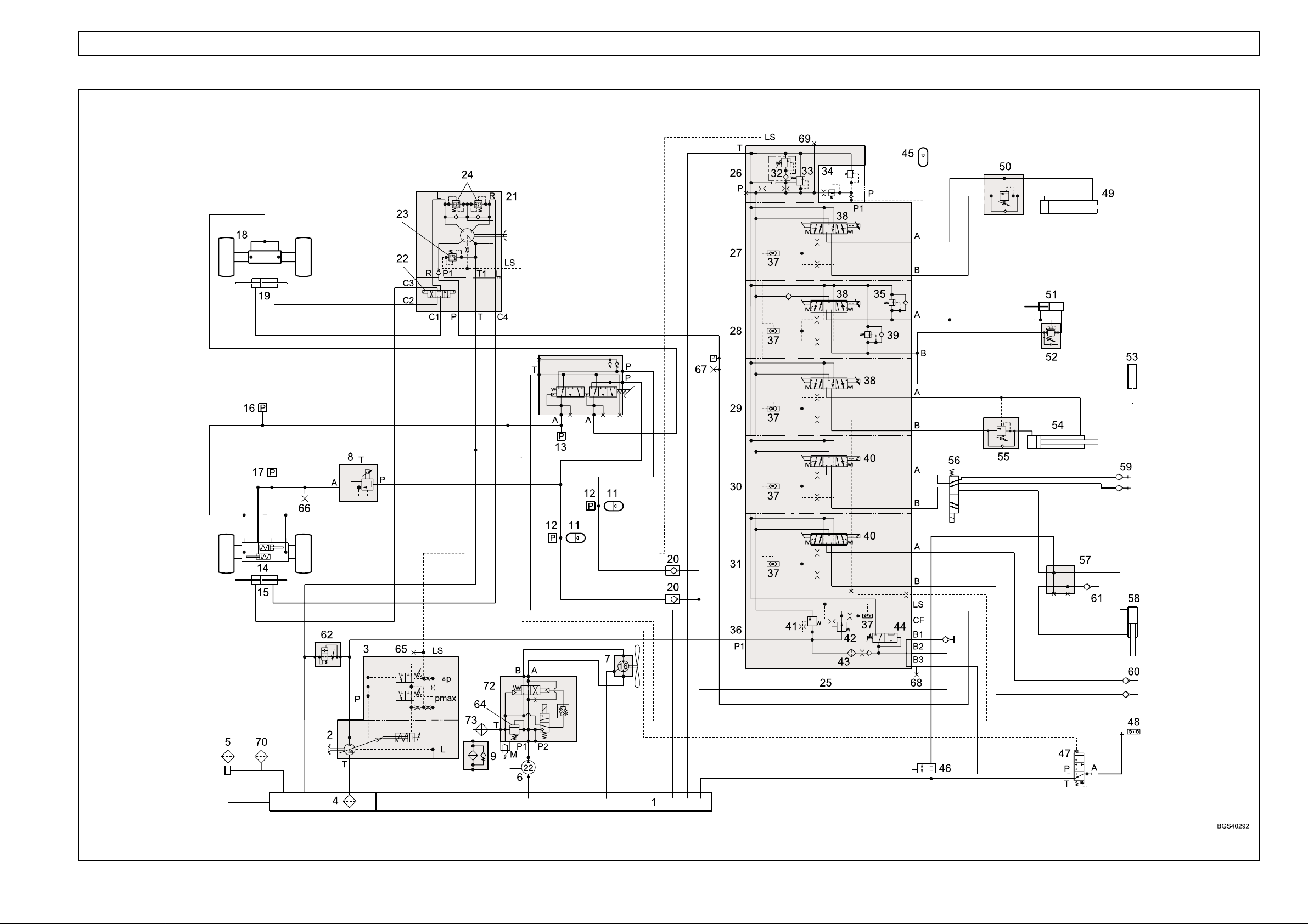
HYDRAULICS 1.2
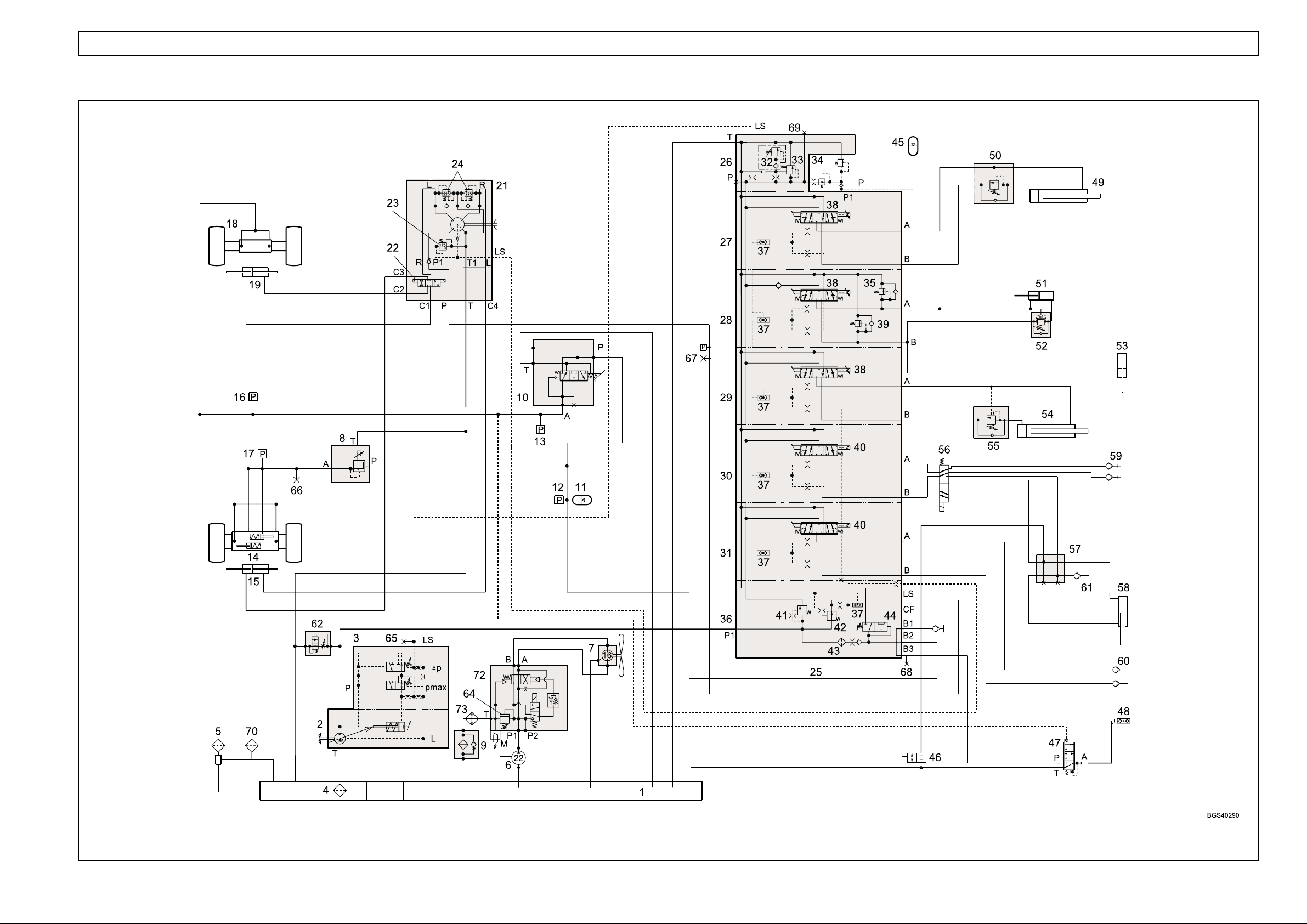
HYDRAULIC CIRCUIT - SINGLE CIRCUIT BRAKING (up to Machine S/No.51200317)

HYDRAULICS 1.3
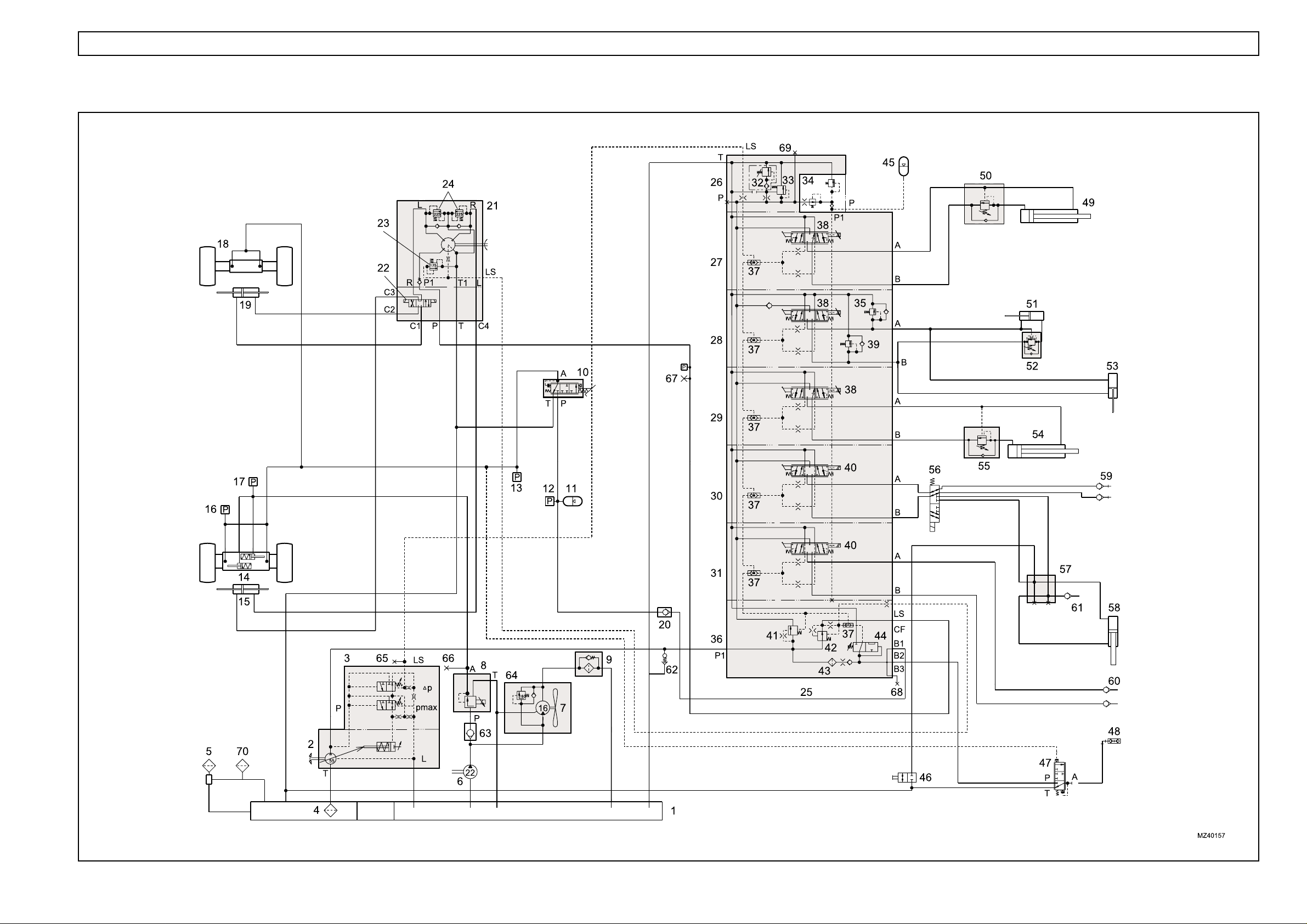
Key to hydraulic circuit - single circuit braking
1. Hydraulic tank (reservoir)
2. Hydraulic pump, load sensing (LS)
3. LS pump compensator
4. Gauze filter (Not Serviceable)
5. Filler/breather
6. Auxiliary hydraulic pump
7. Fan motor
8. Pressure reducing valve (parking brake control)
9. Pressure filter
10. Brake servo valve
11. Accumulator
12. Pressure switch (116 bar)
13. Pressure switch (15 bar)
14. Front axle (park brake actuators)
15. Steering cylinder (front)
16. Pressure switch (5 bar)
17. Pressure switch (16 bar)
18. Rear axle
19. Steering cylinder (rear)
20. Non-return valve
21. Steering control valve (Danfoss OSPF)
22. Steering selector valve (attached to OSPF
valve)
23. Pressure relief valve (175 bar)
24. Shock valve (225 - 245 bar)
25. Hydraulics control valve (PVG 32)
26. Outlet section (PVP)
27. Extension section
28. Crowd/compensator section
29. Lift section
30. 1st auxiliary section (carriage/autohitch)
31. 2nd auxiliary section
32. Pressure relief valve (290 bar)
33. Pressure raising spool
34. Pilot valve
35. Shock valve (175 bar)
36. Inlet section (PVSP)
37. LS shuttle valve
38. Proportional controller
39. Shock valve (265 bar)
40. Controller (not proportional)
41. Priority valve (brakes and steering)
42. Priority valve (steering)
43. Filter
44. Brake accumulator charge valve (BAC)
45. Accumulator
(up to Machine S/No.51200317)
46. Tap
47. Trailer brake valve
48. Trailer brake coupling
49. Extension cylinder
50. Load control valve
51. Crowd cylinder
52. Load control valve
53. Compensator cylinder
54. Lift cylinder
55. Load control valve
56. Diverter valve
57. Manifold
58. Cylinder, autohitch
59. 1st service couplings
60. 2nd service couplings
61. Trailer tipping coupling
62. Start-up valve
63. Non-return valve
64. Pressure relief valve (160 bar)
65. Test point 1 (main system pressure LS)
66. Test point 2 (parking brake release pressure)
67. Test point 3 (steering system pressure)
68. Test point 4 (brake circuit)
69. Test point 5 (main circuit pressure P)
70. Auxiliary breather
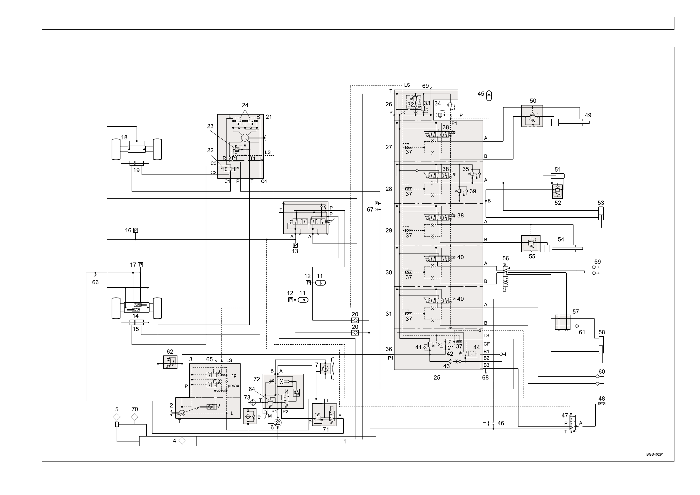
HYDRAULICS 1.4
HYDRAULIC CIRCUIT - SINGLE CIRCUIT BRAKING (from Machine S/No.51200318 to 51200471)

HYDRAULICS 1.5
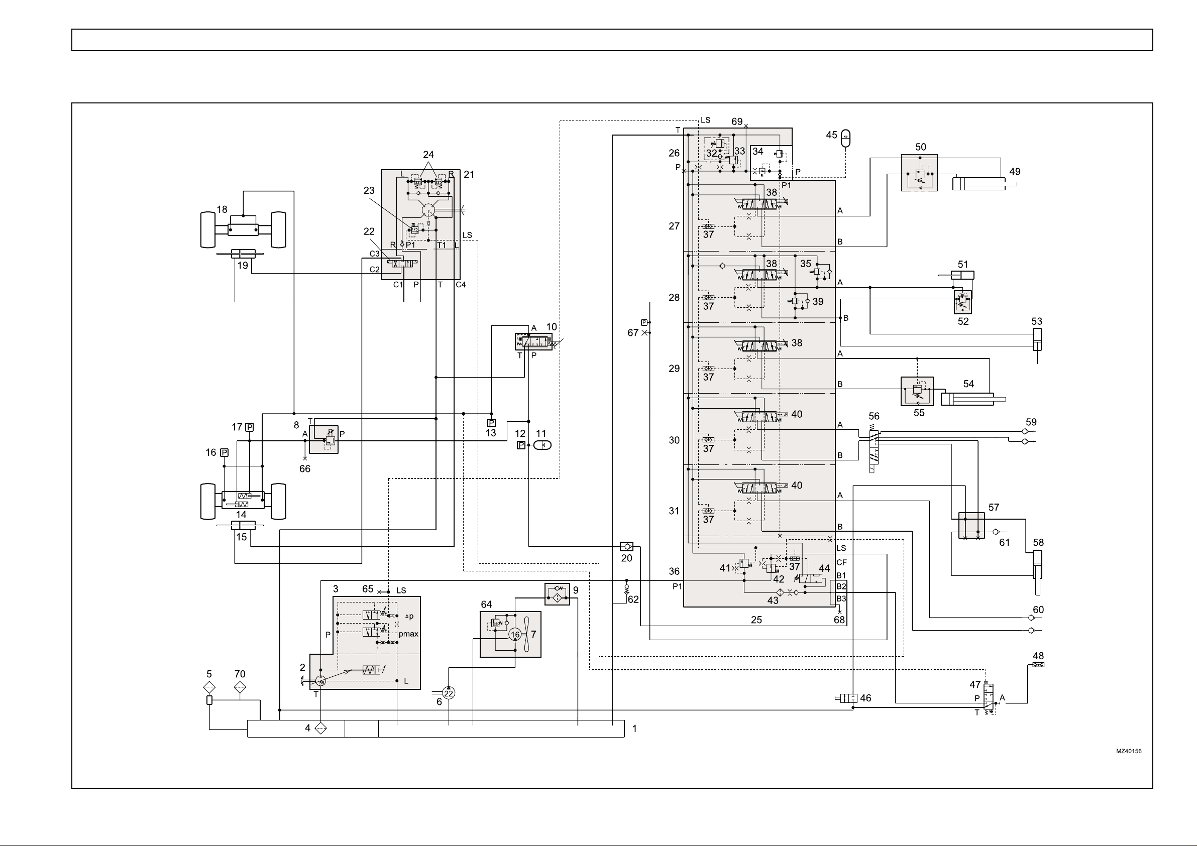
Key to hydraulic circuit - single circuit braking
1. Hydraulic tank
2. Hydraulic pump, load sensing (LS)
3. LS pump compensator
4. Gauze filter (Not Serviceable)
5. Filler/breather
6. Auxiliary hydraulic pump
7. Fan motor
8. Pressure reducing valve (parking brake control)
9. Pressure filter
10. Brake valve
11. Accumulator
12. Pressure switch (116 bar)
13. Pressure switch (15 bar)
14. Front axle (park brake actuators)
15. Steering cylinder (front)
16. Pressure switch (5 bar)
17. Pressure switch (16 bar)
18. Rear axle
19. Steering cylinder (rear)
20. Non-return valve
21. Steering control valve (Danfoss OSPF)
22. Steering selector valve (attached to OSPF
valve)
23. Pressure relief valve (175 bar)
24. Shock valve (225 - 245 bar)
25. Hydraulic control valve (PVG 32)
26. Outlet section (PVP)
27. Extension section
28. Crowd/compensator section
29. Lift section
30. 1st auxiliary section (carriage/autohitch)
31. 2nd auxiliary section
32. Pressure relief valve (290 bar)
33. Pressure raising spool
34. Pilot valve
35. Shock valve (175 bar)
36. Inlet section (PVSP)
37. LS shuttle valve
38. Proportional controller
39. Shock valve (265 bar)
40. Controller (not proportional)
41. Priority valve (brakes and steering)
42. Priority valve (steering)
43. Filter
44. Brake accumulator charge valve (BAC)
45. Accumulator
(from Machine S/No.51200318 to 51200471)
46. Tap
47. Trailer brake valve
48. Trailer brake coupling
49. Extension cylinder
50. Load control valve
51. Crowd cylinder
52. Load control valve
53. Compensator cylinder
54. Lift cylinder
55. Load control valve
56. Diverter valve
57. Manifold
58. Cylinder (autohitch)
59. 1st service couplings
60. 2nd service couplings
61. Trailer tipping coupling
62. Start-up valve
63. NOT FITTED
64. Pressure relief valve (160 bar)
65. Test point 1 (main system pressure LS)
66. Test point 2 (parking brake release pressure)
67. Test point 3 (steering system pressure)
68. Test point 4 (brake circuit)
69. Test point 5 (main circuit pressure P)
70. Auxiliary breather
HYDRAULICS 1.6
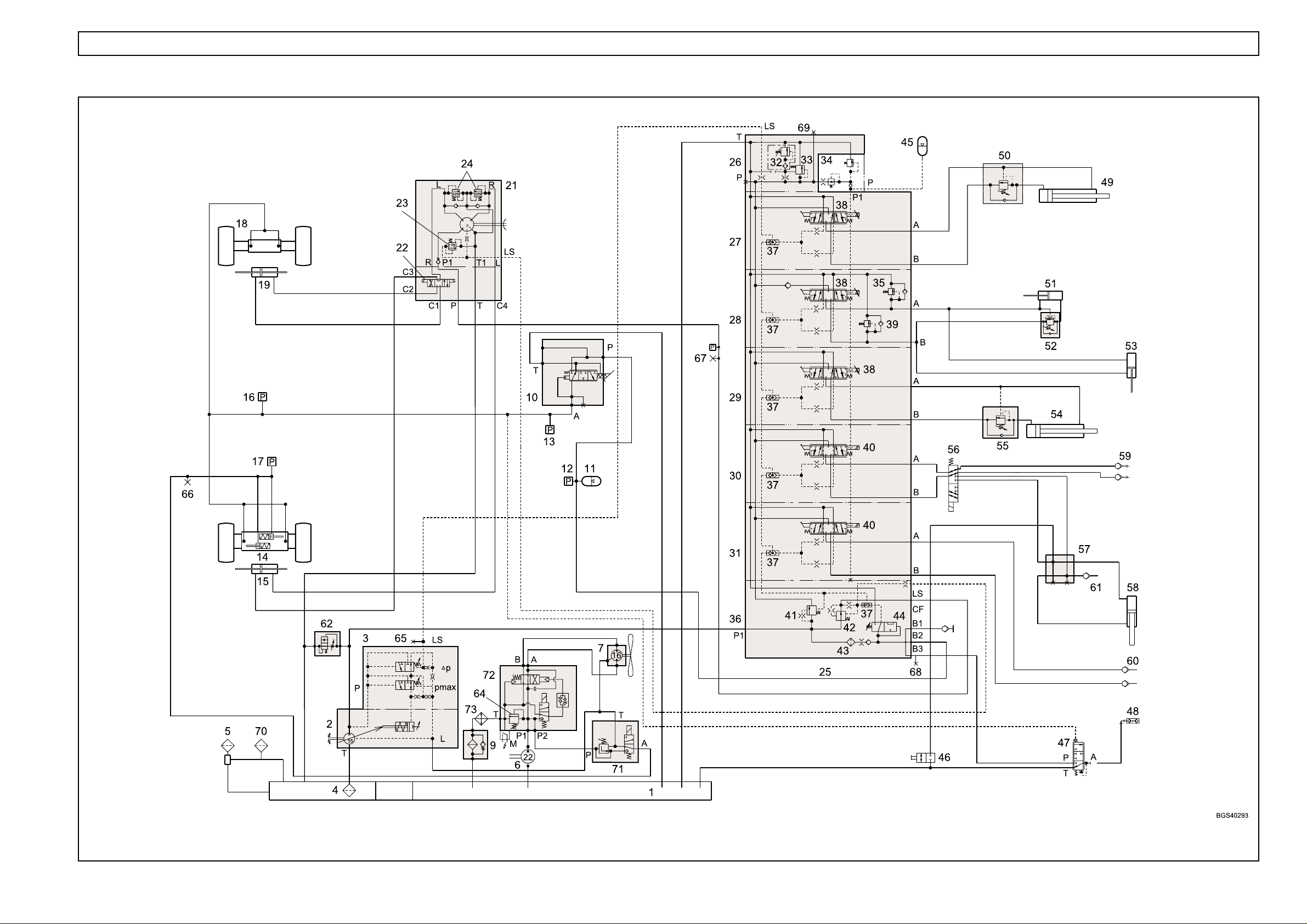
HYDRAULIC CIRCUIT - SINGLE CIRCUIT BRAKING (from Machine S/No. 51200472 to 51200551)

HYDRAULICS 1.7
Key to hydraulic circuit - single circuit braking
1. Hydraulic tank
2. Hydraulic pump, load sensing (LS)
3. LS pump compensator
4. Gauze filter (Not Serviceable)
5. Filler/breather
6. Auxiliary hydraulic pump
7. Fan motor
8. Pressure reducing valve (parking brake control)
9. Pressure filter
10. Brake valve (Safim type)
11. Accumulator
12. Pressure switch (116 bar)
13. Pressure switch (15 bar)
14. Front axle (park brake actuators)
15. Steering cylinder (front)
16. Pressure switch (5 bar)
17. Pressure switch (16 bar)
18. Rear axle
19. Steering cylinder (rear)
20. NOT FITTED
21. Steering control valve (Danfoss OSPF)
22. Steering selector valve (attached to OSPF
valve)
23. Pressure relief valve (175 bar)
24. Shock valve (225 - 245 bar)
25. Hydraulic control valve (PVG 32)
26. Outlet section (PVP)
27. Extension section
28. Crowd/compensator section
29. Lift section
30. 1st auxiliary section (carriage/autohitch)
31. 2nd auxiliary section
32. Pressure relief valve (290 bar)
33. Pressure raising spool
34. Pilot valve
35. Shock valve (175 bar)
36. Inlet section (PVSP)
37. LS shuttle valve
38. Proportional controller
39. Shock valve (265 bar)
40. Controller (not proportional)
41. Priority valve (brakes and steering)
42. Priority valve (steering)
43. Filter
44. Brake accumulator charge valve (BAC)
45. Accumulator
(from Machine S/No.51200472 to 51200551)
46. Tap
47. Trailer brake valve
48. Trailer brake coupling
49. Extension cylinder
50. Load control valve
51. Crowd cylinder
52. Load control valve
53. Compensator cylinder
54. Lift cylinder
55. Load control valve
56. Diverter valve
57. Manifold
58. Cylinder, autohitch
59. 1st service couplings
60. 2nd service couplings
61. Trailer tipping coupling
62. Start-up valve
63. NOT FITTED
64. Pressure regulator, 120 bar
65. Test point 1 (main system pressure LS)
66. Test point 2 (parking brake release pressure)
67. Test point 3 (steering system pressure)
68. Test point 4 (brake circuit)
69. Test point 5 (main circuit pressure P)
70. Auxiliary breather
71. NOT FITTED
72. Fan reverse valve
73. Oil cooler
HYDRAULICS 1.8
HYDRAULIC CIRCUIT - SINGLE CIRCUIT BRAKING (from Machine S/No. 51200552 to 51200727)

HYDRAULICS 1.9
Key to hydraulic circuit - single circuit braking
1. Hydraulic tank
2. Hydraulic pump, load sensing (LS)
3. LS pump compensator
4. Gauze filter (Not Serviceable)
5. Filler/breather
6. Auxiliary hydraulic pump
7. Fan motor
8. NOT FITTED
9. Pressure filter
10. Brake valve (Safim type)
11. Accumulator
12. Pressure switch (116 bar)
13. Pressure switch (15 bar)
14. Front axle (park brake actuators)
15. Steering cylinder (front)
16. Pressure switch (5 bar)
17. Pressure switch (16 bar)
18. Rear axle
19. Steering cylinder (rear)
20. NOT FITTED
21. Steering control valve (Danfoss OSPF)
22. Steering selector valve (attached to OSPF
valve)
23. Pressure relief valve (175 bar)
24. Shock valve (225 - 245 bar)
25. Hydraulic control valve (PVG 32)
26. Outlet section (PVP)
27. Extension section
28. Crowd/compensator section
29. Lift section
30. 1st auxiliary section (carriage/autohitch)
31. 2nd auxiliary section
32. Pressure relief valve (290 bar)
33. Pressure raising spool
34. Pilot valve
35. Shock valve (175 bar)
36. Inlet section (PVSP)
37. LS shuttle valve
38. Proportional controller
39. Shock valve (265 bar)
40. Controller (not proportional)
41. Priority valve (brakes and steering)
42. Priority valve (steering)
43. Filter
44. Brake accumulator charge valve (BAC)
45. Accumulator
(from Machine S/No.51200552 to 51200727)
46. Tap
47. Trailer brake valve
48. Trailer brake coupling
49. Extension cylinder
50. Load control valve
51. Crowd cylinder
52. Load control valve
53. Compensator cylinder
54. Lift cylinder
55. Load control valve
56. Diverter valve
57. Manifold
58. Cylinder, autohitch
59. 1st service couplings
60. 2nd service couplings
61. Trailer tipping coupling
62. Start-up valve
63. NOT FITTED
64. Pressure regulator, 120 bar
65. Test point 1 (main system pressure LS)
66. Test point 2 (parking brake release pressure)
67. Test point 3 (steering system pressure)
68. Test point 4 (brake circuit)
69. Test point 5 (main circuit pressure P)
70. Auxiliary breather
71. Parking brake valve
72. Fan reverse valve
73. Oil cooler
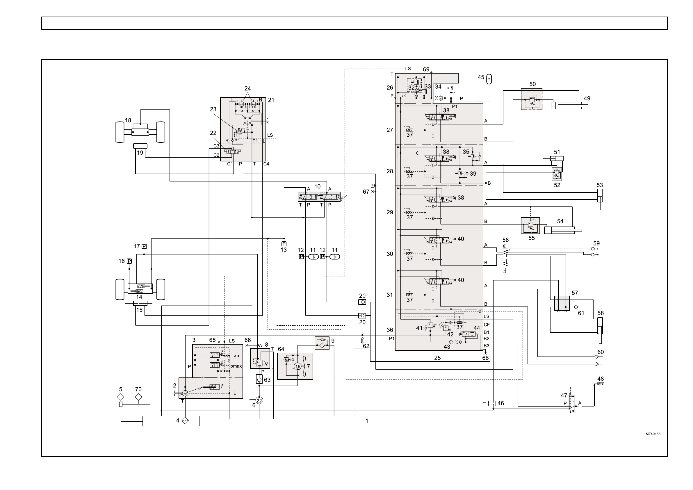
HYDRAULICS 1.10
HYDRAULIC CIRCUIT - DUAL CIRCUIT BRAKING (up to Machine S/No.51200317)

HYDRAULICS 1.11
Key to hydraulic circuit - dual circuit braking
1. Hydraulic tank
2. Hydraulic pump, load sensing (LS)
3. LS pump compensator
4. Gauze filter (Not Serviceable)
5. Filler/breather
6. Auxiliary hydraulic pump
7. Fan motor
8. Pressure reducing valve (parking brake control)
9. Pressure filter
10. Brake valve
11. Accumulator
12. Pressure switch (116 bar)
13. Pressure switch (15 bar)
14. Front axle (park brake actuators)
15. Steering cylinder (front)
16. Pressure switch (5 bar)
17. Pressure switch (16 bar)
18. Rear axle
19. Steering cylinder (rear)
20. Non-return valve
21. Steering control valve (Danfoss OSPF)
22. Steering selector valve (attached to OSPF
valve)
23. Pressure relief valve (175 bar)
24. Shock valve (225 - 245 bar)
25. Hydraulic control valve (PVG 32)
26. Outlet section (PVP)
27. Extension section
28. Crowd/compensator section
29. Lift section
30. 1st auxiliary section (carriage/autohitch)
31. 2nd auxiliary section
32. Pressure relief valve (290 bar)
33. Pressure raising spool
34. Pilot valve
35. Shock valve (175 bar)
36. Inlet section (PVSP)
37. LS shuttle valve
38. Proportional controller
39. Shock valve (265 bar)
40. Controller, (not proportional)
41. Priority valve (brakes and steering)
42. Priority valve (steering)
43. Filter
44. Brake accumulator charge valve (BAC)
45. Accumulator
(up to Machine S/No.51200317)
46. Tap
47. Trailer brake valve
48. Trailer brake coupling
49. Extension cylinder
50. Load control valve
51. Crowd cylinder
52. Load control valve
53. Compensator cylinder
54. Lift cylinder
55. Load control valve
56. Diverter valve
57. Manifold
58. Cylinder, autohitch
59. 1st service couplings
60. 2nd service couplings
61. Trailer tipping coupling
62. Start-up valve
63. Non-return valve
64. Pressure relief valve (160 bar)
65. Test point 1 (main system pressure LS)
66. Test point 2 (parking brake release pressure)
67. Test point 3 (steering system pressure)
68. Test point 4 (brake circuit)
69. Test point 5 (main circuit pressure P)
70. Auxiliary breather
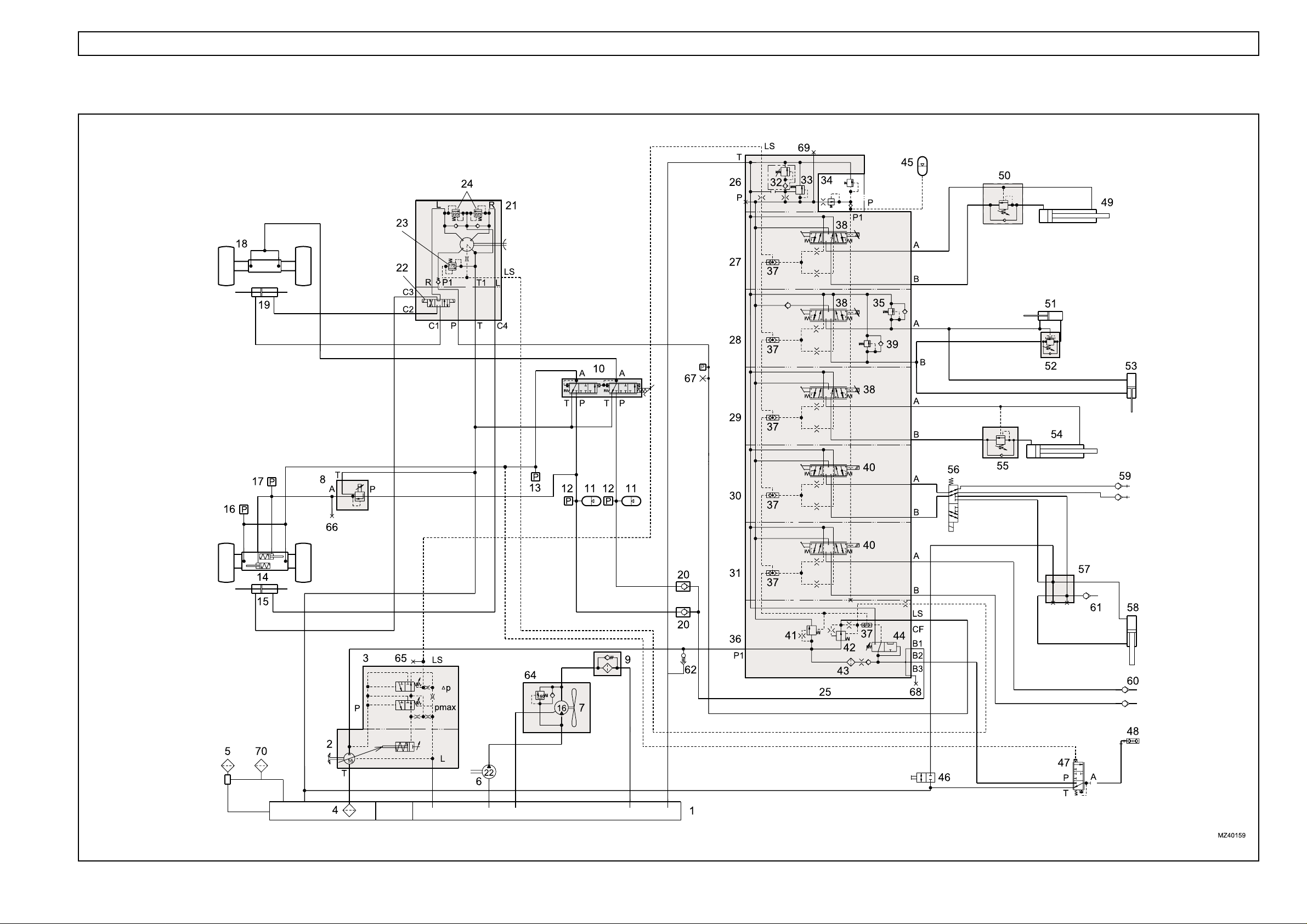
HYDRAULICS 1.12
HYDRAULIC CIRCUIT - DUAL CIRCUIT BRAKING (from Machine S/No.51200318 to 51200471)

HYDRAULICS 1.13
Key to hydraulic circuit - dual circuit braking
1. Hydraulic tank
2. Hydraulic pump, load sensing (LS)
3. LS pump compensator
4. Gauze filter (Not Serviceable)
5. Filler/breather
6. Auxiliary hydraulic pump
7. Fan motor
8. Pressure reducing valve (parking brake
control)
9. Pressure filter
10. Brake valve
11. Accumulator
12. Pressure switch (116 bar)
13. Pressure switch (15 bar)
14. Front axle (park brake actuators)
15. Steering cylinder (front)
16. Pressure switch (5 bar)
17. Pressure switch (16 bar)
18. Rear axle
19. Steering cylinder (rear)
20. Non-return valve
21. Steering control valve (Danfoss OSPF)
22. Steering selector valve (attached to OSPF valve)
23. Pressure relief valve (175 bar)
24. Shock valve (225 - 245 bar)
25. Hydraulic control valve (PVG 32)
26. Outlet section (PVP)
27. Extension section
28. Crowd/compensator section
29. Lift section
30. 1st auxiliary section (carriage/autohitch)
31. 2nd auxiliary section
32. Pressure relief valve, 290 bar
33. Pressure raising spool
34. Pilot valve
35. Shock valve (175 bar)
36. Inlet section (PVSP)
37. LS shuttle valve
38. Proportional controller
39. Shock valve (265 bar)
40. Controller (not proportional)
41. Priority valve (brakes and steering)
42. Priority valve, steering
43. Filter
44. Brake accumulator charge valve (BAC)
45. Accumulator
(from Machine S/No.51200318 TO 512471)
46. Tap
47. Trailer brake valve
48. Trailer brake coupling
49. Extension cylinder
50. Load control valve
51. Crowd cylinder
52. Load control valve
53. Compensator cylinder
54. Lift cylinder
55. Load control valve
56. Diverter valve
57. Manifold
58. Cylinder, autohitch
59. 1st service couplings
60. 2nd service couplings
61. Trailer tipping coupling
62. Start-up valve
63. NOT FITTED
64. Pressure relief valve (160 bar)
65. Test point 1 (main system pressure LS)
66. Test point 2 (Park brake release pressure)
67. Test point 3 (steering system pressure)
68. Test point 4 (brake circuit)
69. Test point 5 (main circuit pressure P)
70 Auxiliary breather
HYDRAULICS 1.14
HYDRAULIC CIRCUIT - DUAL CIRCUIT BRAKING (from Machine S/No.51200472 to 51200551)

HYDRAULICS 1.15
Key to hydraulic circuit - dual circuit braking
1. Hydraulic tank
2. Hydraulic pump, load sensing (LS)
3. LS pump compensator
4. Gauze filter (Not Serviceable)
5. Filler/breather
6. Auxiliary hydraulic pump
7. Fan motor
8. Pressure reducing valve (parking brake
control)
9. Pressure filter
10. Brake valve
11. Accumulator
12. Pressure switch (116 bar)
13. Pressure switch (15 bar)
14. Front axle (park brake actuators)
15. Steering cylinder (front)
16. Pressure switch (5 bar)
17. Pressure switch (16 bar)
18. Rear axle
19. Steering cylinder (rear)
20. Non-return valve
21. Steering control valve (Danfoss OSPF)
22. Steering selector valve (attached to OSPF valve)
23. Pressure relief valve (175 bar)
24. Shock valve (225 - 245 bar)
25. Hydraulic control valve (PVG 32)
26. Outlet section (PVP)
27. Extension section
28. Crowd/compensator section
29. Lift section
30. 1st auxiliary section (carriage/autohitch)
31. 2nd auxiliary section
32. Pressure relief valve, 290 bar
33. Pressure raising spool
34. Pilot valve
35. Shock valve (175 bar)
36. Inlet section (PVSP)
37. LS shuttle valve
38. Proportional controller
39. Shock valve (265 bar)
40. Controller (not proportional)
41. Priority valve (brakes and steering)
42. Priority valve, steering
43. Filter
44. Brake accumulator charge valve (BAC)
45. Accumulator
(from Machine S/No.51200472 TO 512551)
46. Tap
47. Trailer brake valve
48. Trailer brake coupling
49. Extension cylinder
50. Load control valve
51. Crowd cylinder
52. Load control valve
53. Compensator cylinder
54. Lift cylinder
55. Load control valve
56. Diverter valve
57. Manifold
58. Cylinder, autohitch
59. 1st service couplings
60. 2nd service couplings
61. Trailer tipping coupling
62. Start-up valve
63. NOT FITTED
64. Pressure regulator, 120 bar
65. Test point 1 (main system pressure LS)
66. Test point 2 (Park brake release pressure)
67. Test point 3 (steering system pressure)
68. Test point 4 (brake circuit)
69. Test point 5 (main circuit pressure P)
70 Auxiliary breather
71. NOT FITTED
72. Fan reverse valve
73. Oil cooler
HYDRAULICS 1.16
HYDRAULIC CIRCUIT - DUAL CIRCUIT BRAKING (from Machine S/No.51200552 to 51200727)

HYDRAULICS 1.17
Key to hydraulic circuit - dual circuit braking
1. Hydraulic tank
2. Hydraulic pump, load sensing (LS)
3. LS pump compensator
4. Gauze filter (Not Serviceable)
5. Filler/breather
6. Auxiliary hydraulic pump
7. Fan motor
8. NOT FITTED
9. Pressure filter
10. Brake valve (Safim type)
11. Accumulator
12. Pressure switch (116 bar)
13. Pressure switch (15 bar)
14. Front axle (park brake actuators)
15. Steering cylinder (front)
16. Pressure switch (5 bar)
17. Pressure switch (16 bar)
18. Rear axle
19. Steering cylinder (rear)
20. Non-return valve
21. Steering control valve (Danfoss OSPF)
22. Steering selector valve (attached to OSPF valve)
23. Pressure relief valve (175 bar)
24. Shock valve (225 - 245 bar)
25. Hydraulic control valve (PVG 32)
26. Outlet section (PVP)
27. Extension section
28. Crowd/compensator section
29. Lift section
30. 1st auxiliary section (carriage/autohitch)
31. 2nd auxiliary section
32. Pressure relief valve, 290 bar
33. Pressure raising spool
34. Pilot valve
35. Shock valve (175 bar)
36. Inlet section (PVSP)
37. LS shuttle valve
38. Proportional controller
39. Shock valve (265 bar)
40. Controller (not proportional)
41. Priority valve (brakes and steering)
42. Priority valve, steering
43. Filter
44. Brake accumulator charge valve (BAC)
45. Accumulator
(from Machine S/No.51200552 TO 512727)
46. Tap
47. Trailer brake valve
48. Trailer brake coupling
49. Extension cylinder
50. Load control valve
51. Crowd cylinder
52. Load control valve
53. Compensator cylinder
54. Lift cylinder
55. Load control valve
56. Diverter valve
57. Manifold
58. Cylinder, autohitch
59. 1st service couplings
60. 2nd service couplings
61. Trailer tipping coupling
62. Start-up valve
63. NOT FITTED
64. Pressure regulator, 120 bar
65. Test point 1 (main system pressure LS)
66. Test point 2 (Park brake release pressure)
67. Test point 3 (steering system pressure)
68. Test point 4 (brake circuit)
69. Test point 5 (main circuit pressure P)
70 Auxiliary breather
71. Parking brake valve
72. Fan reverse valve
73. Oil cooler
1.18 HYDRAULICS
COMPONENTS
General
NOTE: An identification number in bold type, after an
item, refers to the number of that item in the main
hydraulic schematic illustration.
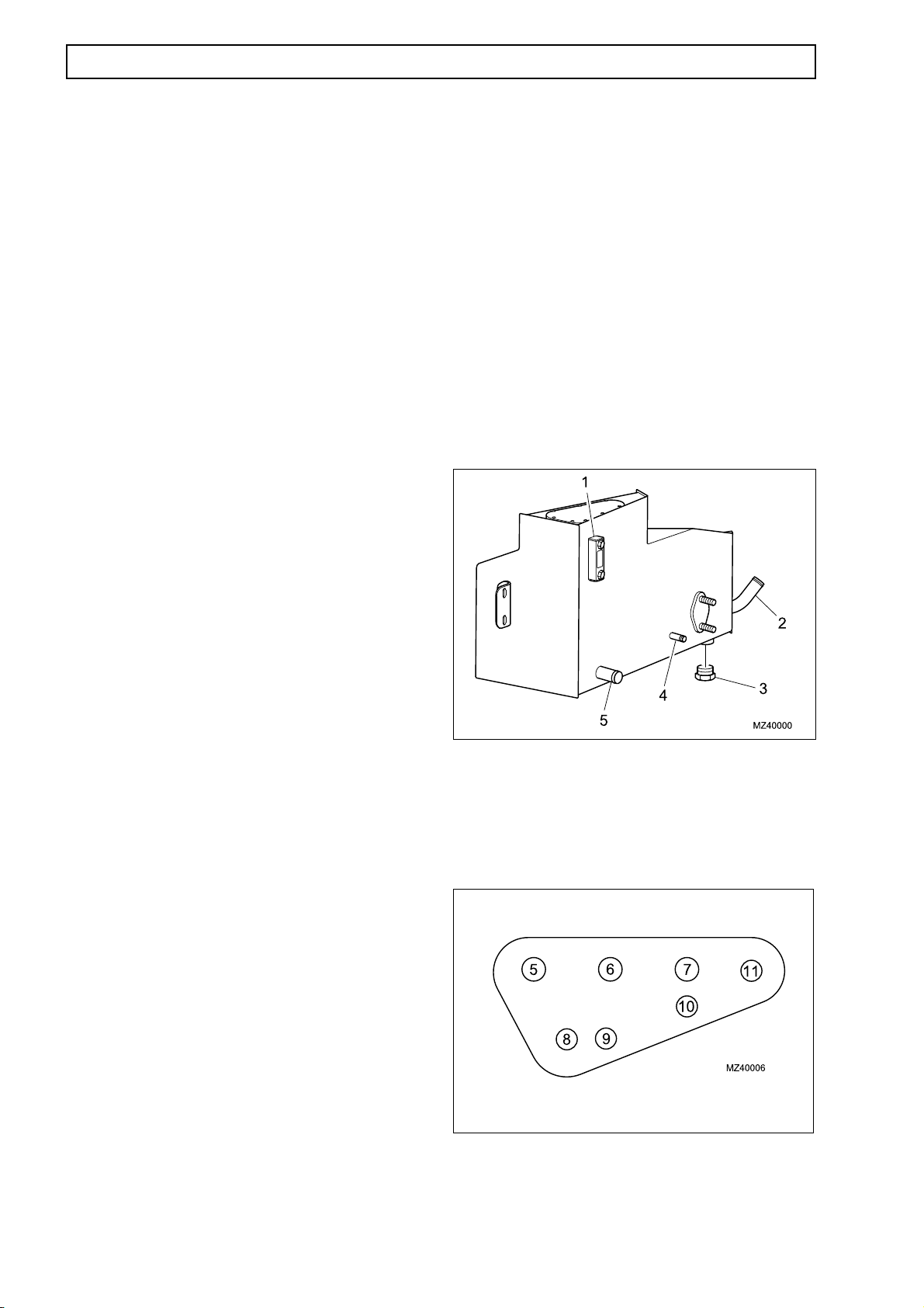
Hydraulic tank (1)
A single hydraulic reservoir feeds the main and
auxiliary systems of the machine. A sight glass is
fitted to check system contents. An internal 40 µm
mesh filter (pre-filtration) separates the clean and
dirty sides of the tank. Both system suction lines are
taken from the clean side of the mesh filter. All
return lines go to a manifold and return fluid to dirty
side of tank for pre filtration.
Specifications:
Nominal tank capacity 67 litres
Total system capacity (oil) 128 litres
Suction line connections to hydraulic tank
1. Sight glass
2. Suction - Main Pump
3. Drain plug
4. Suction - Auxiliary Pump
5. Filler
Return hose connections to hydraulic tank
(up to Machine S/No.51200471)
5. Return from PVG (Main Control Valve)
6. Return from LS Pump and Filter
7. From LS Pump Case Drain
8. Breather (connected to Filler)
9. Return from Brake and Steering circuits
10. From Trailer Brake (optional)
11. Return from Parking Brake PRV
Return hose connections to hydraulic tank
(from Machine S/No.51200472)
5. Return from PVG (Main Control Valve)
6. Return from LS Pump and Filter
7. (Blank fitted)
8. Breather (connected to Filler)
9. Return from Brake circuit
10. From Trailer Brake (optional)
11. Return from Brake and Parking Brake circuit

HYDRAULICS 1.19
Hydraulic Pump (load sensing) (2)
The load sensing hydraulic pump supplies pressure
to operate all services, except the fan motor and
parking brake circuits.
Specifications
Pressure (P) 250 bar (3625 psi)
Pressure (load sensing) 14 bar (200 psi)
Pressure (stand-by) 20 bar (290 psi)
Capacity (flow)
(up to Machine S/No.51200471)
122 l/min @ 2300 rpm
(from Machine S/No.51200472)
122 l/min @ 2200 rpm
Pump compensator (load sensing) (3)
The LS pump compensator controls the stand-by pressure
of the pump when services are not demanding oil, then
causes the pump to swash and deliver full pressure when
a service is operated. The valve also contains a pressure
relief valve.
Tank filter (4)
The filter (not illustrated) is in the hydraulic tank and
separates the return side from the clean side of the tank
and is rated at 40 mm.
Filler/breather (5)
The hydraulic tank is replenished through the filler/
breather (5) which contains a filter rated at 7µm. The
filler breather maintains a positive pressure of 0.3
bar (4 psi) in the hydraulic tank.
Auxiliary hydraulic pump (6)
The auxiliary pump supplies pressure to operate the
engine cooling fan motor and keep the parking brake
off while the engine is running.
Specifications
Pressure 160 bar (2320 psi)
(Max allowable in circuit)
Capacity (flow) 50 l/min @ 2300 rpm
NOTE: On Machines up to S/No.51200317, a non-return
valve (63), between the auxiliary pump (6) and the PRV
(8) maintains line pressure security from any fluctuation
in the auxiliary circuit. This prevents any immediate
application of the parking brake in the event of engine or
hydraulic failure.

1.20 HYDRAULICS
Fan motor (7)
NOTE: Fitted to machines up to S/No.51200471only.
This type of fan motor is hydraulically operated from
the auxiliary circuit and is fitted as part of the engine
cooling system. The fan is secured to the drive shaft
with a woodruff key, nut and tab washer. A cartridge
pressure relief valve (64) is attached to the fan motor.
Specifications:
Pressure relief valve 160 bar (2320 psi)
1. To pressure filter (9)
2. Fan motor (7)
3. Pressure - auxiliary pump (6)
4. Return to tank (1)
Fan reverse motor (7)
NOTE: Fitted to machines from S/No.51200472 only.
5. Pressure relief valve (64)
This type of fan motor is hydraulically operated from the
auxiliary circuit and is fitted as part of the Reverse Fan
engine cooling system. The fan is secured to the drive
shaft with a woodruff key, nut and tab washer.
1. Fan reverse valve (72)
2. Fan motor (7)
3. Fan reverse valve (72)
4. Return to tank (1)

HYDRAULICS 1.21
Pressure Reducing Valve (PRV) - for the
parking brake (8)
NOTE: (Fitted to Machines up to S/No.51200551
only
The Pressure Reducing Valve (PRV) (8) for the
parking brake is electrically controlled from a switch
in the cab (refer to electrical section). The PRV is
located in the engine pod for Machines up to S/
No.51200317 and adjacent to the front axle for
Machine S/No's.51200318 to 51200551. The switch
operates a solenoid on the valve to give proportional
operation. The pressure can be tested using test
point 2 (66 - Refer to Page 1.30), which is in the
output from connection A.
NOTE: The voltage to the solenoid is supplied
through a voltage transformer, to achieve the
proportionality required.
Under no circumstances should
battery voltage be applied to this
solenoid.
Specifications:
Operating pressure 16 bar (230 psi)
Maximum pressure 20 bar (290 psi)
Solenoid 3mm/12vdc/100% prop
Pressure filter (9)
NOTE: (Fitted to Machines up to S/No.51200471 only)
The oil pressure filter (9) is installed in the return line,
between the fan motor (7) and the hydraulic tank (1).
NOTE: (Fitted to Machines from S/No.51200472 only)
The oil pressure filter (9) is installed in the return line,
between the reverse fan valve (72) and the hydraulic
tank (1).
If the filter becomes blocked, a filter blockage warning
light in the cab illuminates and a bypass will open at 3.5
bar (50 psi).
T. Return to hydraulic tank (1)
P. Supply from Auxiliary pump (6)
A. Supply to Parking Brake actuators (14)
When the warning light is illuminated
NO filtration is taking place. Always
change the filter IMMEDIATELY.
Specifications
Filtration 10µm
1. Pressure switch
2. Bypass valve
3. Filter bowl
4. Filter media

1.22 HYDRAULICS
Single circuit brake pressure servo valve
(MICO) (10)
NOTE: Fitted to Machines up to S/No.51200471 only.
The brake pressure servo valve can be either single
or dual depending on the model of the machine.
The operation of the servo valve is proportional to
brake pedal movement. When the brake pedal is
pressed, the valve (10) allows pressure in the
accumulator (11) to apply the brakes. When the brake
pedal is released, the valve (10) closes the pressure line
from the accumulator (11) and diverts brake pressure
from the brake units to the hydraulic tank (1), releasing
the brakes.
Specification
Brake pressure at A 44 bar (640 psi)
Dual circuit brake pressure servo valve
(MICO) (10)
NOTE: Fitted to Machines up to S/No.51200471 only.
With a dual brake servo valve (10), the front and rear
brakes are operated independently of each other by
separate feed and return lines from the servo valve.
Specification
Brake pressure at A
(not shown) 44 bar (640 psi)
Servo Valve - Single circuit brake pedal
P Pressure supply from Accumulator (11)
T Return to Hydraulic Tank (1)
A Supply to Brakes on Front (14) and Rear (18)
Axles
Servo Valve - Dual circuit brake pedal
P Pressure supplies from Accumulators (11)
T Return from Hydraulic Tank (1)
A (not shown) - Supply to Brakes on Front (14)
and Rear (18) Axles

HYDRAULICS 1.23
Single circuit brake pressure servo valve
(SAFIM) (10)
NOTE: Fitted from Machines Serial No.51200472
only
The brake pressure servo valve can be either single or
dual depending on the model of the machine. The
valve is constructed from 3 separate modules, the
master cylinder, valve body and end plate. Brake
pedal travel and braking pressure are set using an
adjusting screw, located on the base on the brake
valve.
The operation of the servo valve (1) is proportional to
brake pedal movement. When the brake pedal is
pressed, a pivoted lever moves a master cylinder,
which positions an associated sprung loaded plunger.
The plunger is in contact with the main shuttle valve
in the valve body Refer to Page 1.84). The shuttle
valve controls the flow of the pressure oil supply from
the brake accumulator. The accumulator is supplied
from the inlet (PVSP) section of the main hydraulic
control valve. When the shuttle valve is moved, the
oil supply from the accumulator is allowed to flow to
the outlet connection in the end plate, which supplies
the front and rear brakes units.
Servo Valve - Single circuit brake pedal
P Pressure supply from Accumulator (11)
T Return to Hydraulic Tank (1)
A Supply to Brakes on Front (14) and Rear (18)
Axles
When the brake pedal is released, spring pressure in
the master valve releases pressure on the shuttle
valve and repositions the brake pedal. The shuttle
valve moves under spring pressure to close the oil
supply from the accumulator and divert residual oil
pressure from the brake system to the hydraulic
tank, releasing the brakes.
Specification:
Brake pressure at A 44 bar (640 psi)
Dual circuit Brake pressure servo valve
(SAFIM) (10)
NOTE: Fitted from Machines Serial No.51200472
only
The construction and operation of the dual brake
servo valve is similar to the single servo valve. The
primary difference is that the front and rear brakes are
operated independently of each other by separate
feed and return lines from the servo valve.
Specification:
Brake pressure at A 44 bar (640 psi)
Servo Valve - Dual circuit brake pedal
P Pressure supply from Accumulators (11)
T Return to Hydraulic Tank (1)
A Supply to Brakes on Front (14) and Rear (18)
Axles

1.24 HYDRAULICS
Accumulator(s) (11)
The nitrogen charged accumulator(s) provide
hydraulic pressure for efficient operation of the brakes
under all pump load conditions. One accumulator is
fitted for the single brake system and two are fitted for
the dual brake system. The accumulator(s) are located
in the chassis behind the cab assembly.
Specifications
Pre-charge pressure 41 bar (595 psi)
Oil capacity 0.75 litre
Pressure switch (12)
The pressure switch illuminates a warning light in the
cab when brake pressure drops to a critical level.
The pressure switch is located adjacent to the
accumulator(s) (11) behind of the cab structure,
forward of the rear axle.
Specification
Operating pressure 116 bar (1682 psi) falling
Pressure switch (transmission dump) (13)
When the transmission dump selector switch in the
cab is operated the pressure switch will disconnect
transmission when the brakes are applied. The
pressure switch is located adjacent to the
transmission drop box, above the drive shaft.
Specification
Operating pressure 15 bar (217 psi) rising

HYDRAULICS 1.25
Front axle (14)
The front axle contains double reduction bevel and
planetary hub reduction gears and a limited slip
differential. Braking is by inboard multi-disc units, the
axle also contains a parking brake.
The outboard wheel hubs are steerable, operated
by a steering cylinder (15) attached to the axle.
Steering cylinder (front) (15)
The front steering cylinder is a double acting
hydraulic cylinder, supplied with pressure operating
oil from the Steering Control Valve (21). The two
cylinder rams have a ball joint end fitting, which
connect to the swivel hubs for the front wheels. The
front steering cylinder is attached to the rear of the
front axle, above the drive shaft housing.
Specification
Stroke (lock to lock) 200 mm
Bore 85 mm
Pressure switch (brake light) (16)
When the brake pedal is depressed the pressure
switch operates and illuminates the brake stoplights
at the rear light clusters. The switch is located in the
brake pipes on the right side of the front axle.
Specification
Operating pressure 5 bar (72 psi) rising

1.26 HYDRAULICS
Pressure switch (parking brake) (17)
When the parking brake pressure (17) falls below 16
bar (232 psi) the pressure switch illuminates a
warning light in the cab. The switch is located in the
brake pipes on the right side of the front axle.
If light is on, parking brake has been applied.
If light comes on when parking brake is
not applied, stop vehicle and investigate
fault.
Specification
Operating pressure 16 bar (232 psi) rising
Rear axle (18)
The rear axle (18) contains double reduction bevel
and planetary hub reduction gears and a limited slip
differential. Braking is by inboard multi-disc units
(when taken as an option).
The outboard wheel hubs are steerable, operated by
a steering cylinder (19) attached to the axle.
Steering cylinder (rear) (19)
The rear steering cylinder (19) is a double acting
hydraulic cylinder, supplied with pressure operating
oil from the Steering Control Valve. The two cylinder
rams have a ball joint end fitting, which connect to
the swivel hubs for the front wheels. The rear
steering cylinder is attached to the front of the rear
axle, above the drive shaft housing.
Specification
Stroke (lock to lock) 200 mm
Bore 85 mm
Non-return valve (20)
The non-return valve (NRV) allows pressure supply oil
to be supplied from the main hydraulic control valve to
the Brake Servo valve. The NRV (20) prevents oil
from the brake servo valve returning into the main
control valve. This valve is fitted to Machines for
certain markets only.

HYDRAULICS 1.27
Steering valve (21)
The steering system is dynamic and fully load
sensing and is supplied with pressure operating oil
from the load sensing (LS) output of the inlet section
(PVSP) (36) on the main hydraulic control valve (25).
The valve contains a PRV (23) and two shock valves
(24).
Steering in Neutral position
When the steering valve is in the neutral position, the
spring in the priority valve (42) moves the valve to
allow the oil to pass freely, from the load sensing
line, through the priority valve (42) and the steering
control valve (21) to the hydraulic tank (1). The oil
supply from the hydraulic pump (2) is locked.
As back pressure increases at the spool of the
priority valve (42), the valve spring is compressed and
the spool moves to allow oil to flow to the working
hydraulics.
STEERING - NEUTRAL POSITION

1.28 HYDRAULICS
Steering in Operation
As the steering wheel is turned, the rotary valve
proportionally directs the oil flow from the LS line of
the inlet section (PVSP) (36) to the steering selector
valve (21) (not shown). The LS line is not fully closed
until the rotary valve is fully open. When the steering
input is stopped, the rotor passages close, steering
input stops and the system returns to the loadsensing mode.
Specification
Type OSPF250LS
PRV 170-175 bar (2465-2537 psi)
Shock valve 225-245 bar (3262-3552 psi)
STEERING - RIGHT TURN OPERATION
Pressure relief valve (23)
If an overpressure condition exists, a pressure relief
valve (PRV) will bypass pressure oil from the spring
side of the priority valve (42) to the hydraulic tank (1).
The upstream oil pressure is greater and moves the
spool valve, against the spring, allowing oil to be
supplied to the working hydaulics.
Specification:
Operating pressure 175 bar (254 psi)

HYDRAULICS 1.29
Steering selector valve (22)
The steering selector valve is solenoid operated and
diverts oil to the respective ports of the steering
cylinders. Three modes of steering are available by
selecting the steering mode switch in the cab to give
either two-wheel steering (front wheels), four-wheel
steering or ‘crab’ steering.
The machine must always be
stationary before changing steering
modes.
C 1 To rear steering cylinder (19)
C 2 To rear steering cylinder (19)
C 4 To front steering cylinder (15)
T Return to hydraulic tank (1)
P From inlet section (36) CF - Line
C 3 T o front steering cylinder (15)
O OSPF250 valve
A Adapter
E Selector valve
LS From inlet section (36) LS – Line

1.30 HYDRAULICS
Control valve (25)
The control valve consists of up to five individual spool
valves, with common pressure and return lines, linked
together by an inlet and outlet cover. The inlet
(PVSP) (36) contains a priority valve (43) (steering)
module and brake accumulator charge valve (44). The
spools, outlet cover and PSVP are secured together
with tie bolts. The individual components of the valve
described are (26) to (44).
Key to control valve
NOTE: Numbers in bold type refer to identification
numbers on main hydraulic schematic.
1 Outlet section (PVP) (26)
2 Test Point 1 (65)
3 Boom extend/retract section (27)
4 Crowd/compensator section (28)
5 Boom lift/lower section (29)
6 1st auxiliary section (30)
7 2nd auxiliary section (31)
8 Manual operation module
9 Brake and Accumulator Charge valve (BAC) (44)
10 Steering Priority Valve (42)
11 Inlet Section (PVSP) (36)
12 Brakes/Steering Priority Valve (12)
Key to control valve (continued)
13 Tie bolt
14 Washer
15 Nut
16 LS Shuttle Valve (37)
17 Pressure supply (36)
18 Brake and Accumulator Charge valve (BAC) (44)
19 Steering Valve (22)
20 Electric module (38, 40)
21 Test Point 4 (68)
22 2nd Service Couplings (60)
23 2nd Service Couplings (60)
24 Diverter Valve (56)
25 Diverter Valve (56)
26 Load Control Valve (55)
27 Lift Cylinder (54)
28 Relief valve, crowd back (39)
29 Load Control Valve (52)
30 Crowd Cylinder (51)
31 Relief valve, crowd forward (36)
32 Test {Point 5 (69)
33 Extension Cylinder (49)
34 Load Control Valve (50)
35 Relief valve, main system (32)
36 Pilot pressure regulator (34)
37 Hydraulic Tank (1)
HYDRAULICS 1.31
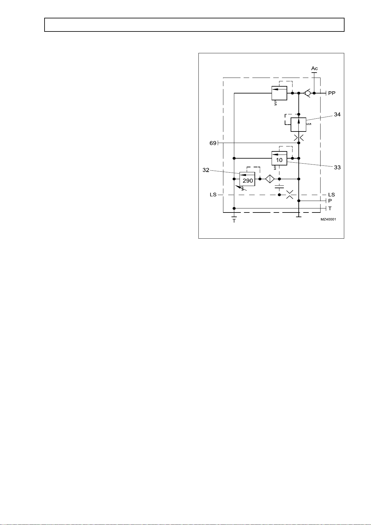
Outlet section (PVP) (26)
Ac Accumulator
PP Pilot pressure
LS Load sensing
T Return to tank
P Pressure
32 Main pressure relief valve (RV1-290 bar)
34 Pilot pressure regulator (14 bar)
33 Compensator (pressure raising spool) (10 bar)
69 Test point
Function
The closed centre provides for ultimate system protection
and the provision of pilot pressure for the operation of the
spools.

1.32 HYDRAULICS
Extension section (27)
A Port A - connection to service
B Port B - connection to service
PP Pilot pressure
LS Load sensing
T Return to tank
P Pressure
(37) LS shuttle valve
(38) Controller, proportional
Function
Extension service is fully proportional and operated
electrically to provide oil flow to the extension circuit.
When the spool is moved from the neutral position, oil
at P (standby pressure 20 bar (290 psi)) is delivered
to the consumer (service). The oil at the consumer
meets a resistance (i.e. to move the piston) and the
pressure at P rises to overcome this force. The P line
is connected permanently to the LS line; therefore the
pump receives a signal to swash to the required
position to provide the pressure required to overcome
the resistance. The pressure at P will therefore be the
LS pressure plus the standby pressure of 20 bar (290
psi).
The pump will always react to the highest pressure
requested when more than one service is operated by
virtue of the LS shuttle valve in each section.
When the valve returns to neutral the pressure at P
drops and therefore the pressure in the LS line also
drops.
The spool is operated by pilot oil pressure delivered
by the electrical actuator under the command of the
‘Solo’ joystick and is fully proportional.
In neutral the spool is ‘half-motored’, connecting port
B to the T line.

HYDRAULICS 1.33
Crowd section (28)
A Port A - connection to service
B Port B - connection to service
PP Pilot pressure
LS Load sensing
T Return to tank
P Pressure
(35) Shock and anti-cavitation valve - Port A
(RV2-175 bar)
(37) LS shuttle valve
(38) Controller, proportional
(39) Shock and anti-cavitation valve - Port B
(RV3-265 bar)
Function
Crowd service is fully proportional and operated
electrically to provide oil flow to the crowd circuit.
When the spool is moved from the neutral position,
oil at P (standby pressure 20 bar (290 psi)) is
delivered to the consumer (service). The oil at the
consumer meets a resistance (i.e. to move the
piston) and the pressure at P rises to overcome this
force. The P line is connected permanently to the LS
line; therefore the pump receives a signal to swash to
the required position to provide the pressure required
to overcome the resistance. The pressure at P will
therefore be the LS pressure plus the standby
pressure of 20 bar (290 psi).
The pump will always react to the highest pressure
requested when more than one service is operated by
virtue of the LS shuttle valve in each section.
When the valve returns to neutral the pressure at P
drops and therefore the pressure in the LS line also
drops.
The spool is operated by pilot oil pressure delivered
by the electrical actuator under the command of the
‘Solo’ joystick and is fully proportional.
In neutral the spool is closed’, neither of the
consumer ports A or B are connected to the T line.
This enables self-levelling operation from the
compensator cylinder.
To protect the circuit, shock valves are provided in
both A and B ports.

1.34 HYDRAULICS
Lift section (29)
A Port A - connection to service
B Port B - connection to service
PP Pilot pressure
LS Load sensing
T Return to tank
P Pressure
(37) LS shuttle valve
(40) Controller, proportional
Function
Lift service is fully proportional and operated
electrically to provide oil flow to the lift circuit.
When the spool is moved from the neutral position,
oil at P (standby pressure 20 bar (290 psi)) is
delivered to the consumer (service). The oil at the
consumer meets a resistance (i.e. to move the
piston) and the pressure at P rises to overcome this
force. The P line is connected permanently to the LS
line; therefore the pump receives a signal to swash to
the required position to provide the pressure required
to overcome the resistance. The pressure at P will
therefore be the LS pressure plus the standby
pressure of 20 bar (290 psi).
The pump will always react to the highest pressure
requested when more than one service is operated
by virtue of the LS shuttle valve in each section.
When the valve returns to neutral the pressure at P
drops and therefore the pressure in the LS line also
drops.
The spool is operated by pilot oil pressure delivered
by the electrical actuator under the command of the
‘Solo’ joystick and is fully proportional.
In neutral the spool is ‘half-motored’, connecting port
B to the T line.

HYDRAULICS 1.35
1st service (30)/2nd service (31) section
A Port A - connection to service
B Port B - connection to service
PP Pilot pressure
LS Load sensing
T Return to tank
P Pressure
(37) LS shuttle valve
(40) Controller, non-proportional
Function
1st service/2nd service is non-proportional and
operated electrically to provide oil flow to the 1st
service/2nd service circuit.
When the spool is moved from the neutral position,
oil at P [standby pressure 20 bar (290 psi)] is
delivered to the consumer (service). The oil at the
consumer meets a resistance (i.e. to move the
piston) and the pressure at P rises to overcome this
force. The P line is connected permanently to the LS
line; therefore the pump receives a signal to swash to
the required position to provide the pressure required
to overcome the resistance. The pressure at P will
therefore be the LS pressure plus the standby
pressure of 20 bar (290 psi).
The pump will always react to the highest pressure
requested when more than one service is operated by
virtue of the LS shuttle valve in each section.
When the valve returns to neutral the pressure at P
drops and therefore the pressure in the LS line also
drops.
The spool is operated by pilot oil pressure delivered
by the electrical actuator under the command of the
‘Solo’ joystick.
These sections, although electrically controlled, are
non-proportional. Operation of the buttons on the
‘Solo’ joystick operate these sections as an on-off
switch.
In neutral the spool is closed, neither of the
consumer ports A and B are connected to the T line.

1.36 HYDRAULICS
Inlet section (PVSP) (36)
LS (1) Load sensing (to steering valve)
CF Steering valve
B1 Main brake
B2 Trailer brake (optional)
B3 Pressure test point (67)
LS Load sensing
T Return to tank
P Pressure
A BAC valve spring
(37) LS shuttle valve
(41) Priority valve
(42) Steering priority valve (compensator)
(43) Filter
(44) Brake accumulator charge (BAC)
(68) Test point
Function
The inlet section (PVSP) provides oil to:
(a) The brake circuit through the BAC valve (44), this
gives a charge of between 138-159 bar (2000-2300
psi) and operates in preference to all other services.
Brake charge pressure can be tested at test point B3
(68).
(b) The steering circuit with oil on demand by the
steering priority valve (42).
The oil arriving at P is delivered to the BAC valve and
onto the accumulators, the resistance to charging the
accumulator causes the pressure to rise at P which,
as it is connected to the LS line via the BAC valve,
signals to the pump. The pump responds by delivering
oil at the required pressure.
The system charges at 138 bar and stops charging at
159 bar. At the upper limit 159 bar, the oil pressure at
P overcomes the force of the BAC valve spring (A)
and closes the connection between P and LS; the
pump therefore goes to standby. When the pressure
in P falls below 138 bar, the spring force opens the
valve and the system recharges.
At the same time, pump pressure is supplied to the
steering unit via the CF port. If the steering is not
being used, the pump at standby pressure overcomes
the spring force in the priority valve (41) and supplies
oil to the other consumers.
When the steering wheel is moved, the resistance to
oil from the steering cylinders builds in the CF line.
This is also sensed by the LS line, which, as it is
linked to the steering priority valve (42). makes sure
steering is given priority as well as signalling the
pressure requirement to the pump.

HYDRAULICS 1.37

1.38 HYDRAULICS
Accumulator (45)
The nitrogen charged accumulators (1) provide
hydraulic pressure for operation of spools when
engine is switched off. The accumulators are
attached to brackets, located adjacent to the main
hydraulic control valve (25).
Specifications
Pre-charge pressure 7 bar (100 psi)
Oil capacity 0.75 litre
Tap (46)
The tap valve (3) (46) is located on the rear service
plate (1) and connects the return line from the
autohitch manifold (2) to the hydraulic tank. When
operated, the tap valve (3) allows return oil from the
autohitch manifold(2) to flow to the hydraulic tank.
The return line downstream from the tap valve (3)
connects to the return line from the trailer brake
valve (4). The tap valve (3) is used to convert the
dual acting service for the autohitch to single acting
service for trailer tipping.
Trailer brake valve (47)
The trailer brake valve, if fitted, is located on the
rear service plate and is connected to the inlet
section (36) of the main hydraulic control valve
(25), the hydraulic tank (1) and the trailer coupling
(48). When a trailer brake is connected to the
trailer brake coupling and the brakes are applied,
the porting of the valve applies proportional
pressure to the trailer brake. When the brakes are
released, the valve diverts the hydraulic oil to the
hydraulic tank (1).
1 Accumulators
1 Service plate 3 Tap valve (46)
2 Manifold 4 Trailer valve
The valve is pilot operated by a signal taken from
the operation of the service brakes.
Key to Trailer Brake Valve
1 Outlet to Trailer Brake Coupling (48)
2 Inlet from Tap (46)
3 Pressure supply (B2)
Trailer brake coupling (48)
The trailer brake coupling (1) is a self-sealing, quick
release coupling, located on the rear service plate
(2). The coupling is used to connect a trailer
braking system to the trailer brake valve (47), if
fitted.
Key to Trailer Brake Coupling
1 Trailer brake coupling
2 Rear service plate

HYDRAULICS 1.39
Extension cylinder (49)
The boom extension cylinder is fitted inside the boom
of the machine and is supplied with operating pressure
oil from a load control valve (50).
Specification:
Type K 50 Stroke 1971 mm
Bore 80 mm
Type K 60 Stroke 2111 mm
Bore 80 mm
Type K 70 Stroke 2917 mm
Bore 80 mm
Load control valve (50)
The load control valve for the extension cylinder is
fitted in the pressure oil supply lines, between the
extension section (27) and the boom extension
cylinder (49). The valve prevents any load
movement in the event of hose bursts or leakage. If
the valve is defective, a complete new cartridge
must be fitted.
The load control valve is factory set and
should never be dismantled or adjusted
except for resealing.
Key to Load Control Valve
1. From the extension section (27)
2. Extension cylinder (rod side)
3. Extension cylinder (full bore side)
4. From the extension section (27)
5. Pilot pressure
6. Supply pressure
7. Pressure relief

1.40 HYDRAULICS
Crowd cylinder (51)
The crowd cylinder is fitted inside the head of the
boom and controls the operation of the head
attachments. The crowd cylinder is supplied with
operating pressure oil from the crowd/compensator
section (28) and a load control valve (52).
Specification:
Stroke 350 mm
Bore 125 mm
Load control valve (52)
The load control valve for the crowd cylinder is
fitted between the crowd cylinder (51) and the
crowd/compensator section (28). The valve
prevents any load movement in the event of hose
bursts or leakage. If the valve is defective, a
complete new cartridge must be fitted.
The load control valve is factory set
and should never be dismantled or
adjusted except for resealing.
Key to Load Control Valve
1. From the crowd/compensator section (28)
2. Crowd/compensator cylinder (rod side)
3. Crowd/compensator cylinder (full bore
side)
4. From the crowd/compensator section (28)
5. Pilot pressure
6. Supply pressure
7. Pressure relief
HYDRAULICS 1.41
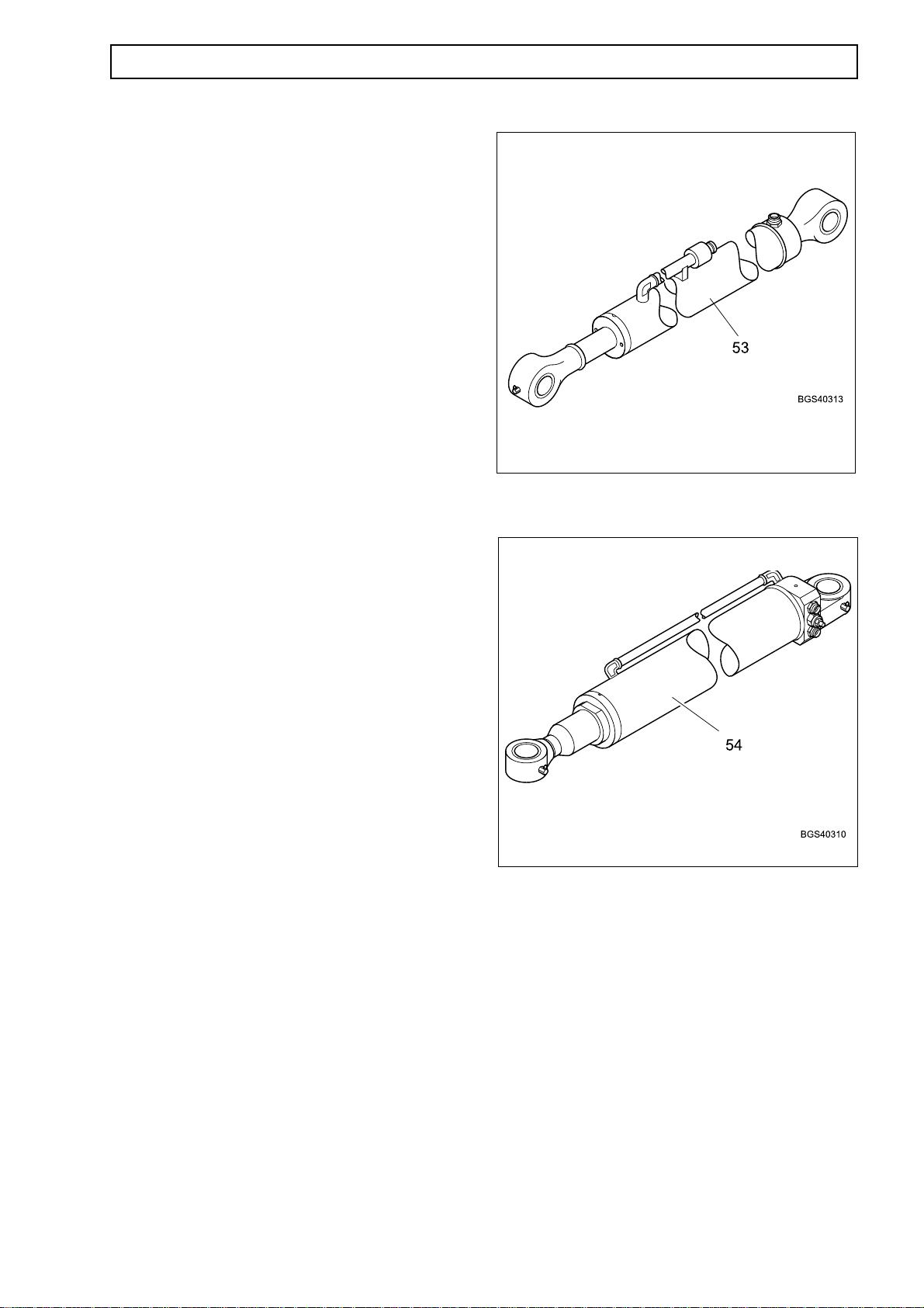
Compensator cylinder (53)
The compensator extension cylinder is fitted below
and to the rear of the extension boom and is
connected to the load control valve (52) and the
crowd/compensator section (28).
Specification
Stroke 750 mm
Bore 63 mm
ILLUSTRATION REQUIRED (IPC 723)
Lift cylinder (54)
The lift cylinder is fitted below and forward of the
extension boom. The lift cylinder is supplied with
operating pressure oil from the lift section (29) and
a load control valve (55).
Specification
Type K50 Stroke 1325 mm
Bore 125 mm
Type K60 Stroke 1325 mm
Bore 125 mm
Type K70 Stroke 1400 mm
Bore 125 mm

1.42 HYDRAULICS
Load control valve (55)
The load control valve for the lift cylinder is fitted in
the pressure oil supply lines, between the lift section
(29) and the lift extension cylinder (54). The valve
prevents any load movement in the event of hose
bursts or leakage. If the valve is defective, a
complete new cartridge must be fitted.
The load control valve is factory set
and should never be dismantled or
adjusted except for resealing.
Key to Load Control Valve
1. From the lift section (29)
2. Lift cylinder (rod side)
3. Lift cylinder (full bore side)
4. From the lift section (29)
5. Pilot pressure
6. Supply pressure
7. Pressure relief

HYDRAULICS 1.43
Diverter valve (56)
The diverter valve, if fitted, is attached to a bracket,
which is fitted to the rear service plate, to the left
side of the chassis member. The valve is
connected between the 1st auxiliary section (30)
and the 1st service couplings (59) and autohitch
manifold (57).
The valve is solenoid operated and selected by a
rocker switch in the cab. When selected, the valve
diverts oil from the 1st auxiliary service to the rear
of the machine where it can be utilized to operate
trailer tipping or autohitch.
Specification:
Solenoid Operating voltage 12V DC
Key to Diverter Valve
1 To the 1st service coupling (59)
2 To the 1st service coupling (59)
3 Autohitch manifold (57)
4. Autohitch manifold (57)
5-10. Not used
11. To the 1st auxiliary section (30)
12. To the 1st auxiliary section (30)
Manifold (57)
The manifold is attached to the rear service plate
and is located between the autohitch cylinder (58)
and the diverter valve (56). The manifold is used to
deliver oil to the autohitch or trailer tipping services.

1.44 HYDRAULICS
Autohitch cylinder (58)
The autohitch cylinder, if fitted, is located on the
rear of the machine and is used to automatically
connect and lift a trailer onto the machine. The
pressure oil supplies to the autohitch cylinder are
from the autohitch manifold (57).
Specification
Stroke 325 mm
Bore 60 mm
1st service couplings (59).
The 1st service couplings (not illustrated) are of the
quick-release type and are used to attach hydraulic
services to the front of the machine.
2nd service couplings (60)
The 2nd service couplings are of the quick-release
type and, if fitted, are used to attach a second
hydraulic attachment to the front of the machine.
Trailer tipping connection (61)
The trailer tipping connection (not illustrated) is of
the quick-release coupling type and, if fitted,
connects hydraulic supplies to the trailer tipping
service.
Start-up valve (62)
The start-up valve is fitted in the hydraulic supply
line between the LS hydraulic pump (2) and the
control valve PVSP inlet section (36). An internal
spring valve opens the start-up valve to divert fluid
to the hydraulic tank (1) when the engine is being
started, offloading the build-up of pressure. When
the LS hydraulic pump builds up sufficient pressure,
the fluid pressure overcomes the spring valve,
which closes and prevents fluid from flowing back to
the hydraulic tank (1).

HYDRAULICS 1.45
Non-return valve (63)
(Up to Machine S/No.51200317 only)
This is a simple non-return valve, which maintains
system pressure for the parking brake circuit, in the
event of hydraulic or engine failure.
Pressure relief valve (64)
(Up to Machine S/No.51200471 only)
The cartridge pressure relief valve is attached to the
cooling fan motor (7) and relieves excess pressure
in the hydraulic fluid supply to the motor. The valve
relieves pressure by diverting hydraulic fluid flow to
the hydraulic tank (1).
Specifications
Pressure relief valve 160 bar (2320 psi)
Breather (70)
The breather is fitted to the overflow line from the
filler neck to tank return and ensures that the
hydraulic tank is vented. This prevents any build up
of positive or negative air pressure inside the tank,
which would cause damage to the tank or restrict
fluid flow.

1.46 HYDRAULICS
Parking brake valve (71)
(From Machine S/No.51200552 only)
The parking brake valve is fitted between the
hydraulic tank (1), the cooling fan motor (7) and the
fan reverse valve circuit (72). The valve is solenoid
operated from a switch in the operators cab and
applies the parking brake.
The valve is supplied with hydraulic fluid from the
fan reverse valve (72) and has a solenoid operated
valve and a pressure relief valve. When selected
by the operator, the solenoid valve operates to
supply hydraulic fluid to the parking brake actuators
on the front axle. When de-selected, the valve
releases the hydraulic fluid pressure to the parking
brake and returns the fluid flow to the hydraulic tank
(1).
Specifications
Pressure relief valve 18 bar (261 psi) max
Solenoid voltage 12V DC
Key to Parking Brake Valve
1. Solenoid operated valve
2. Pressure relief valve
A Supply to Parking Brake actuators (14)
P Supply from Fan Reverse Valve (72)
T Return to hydraulic tank (1)

HYDRAULICS 1.47
Fan reverse valve (72)
(From Machine S/No.51200472 only)
The fan reverse valve is fitted between the
hydraulic tank (1), the cooling fan motor (7) and the
parking brake valve (71). The valve is manually
operated from a switch in the operators cab and
reverses the direction of rotation of the engine
cooling fan. This enables debris that is blocking the
radiator to be blown clear to restore correct cooling.
The valve is supplied with hydraulic fluid from the
auxiliary hydraulic pump (6) and has a solenoid
operated valve, servo valve, pressure relief valve
and a temperature operated switch. In normal
operating conditions, the hydraulic fluid supply from
the auxiliary pump (6) is directed by the solenoid
valve to the fan motor (7). The return fluid is
directed by the solenoid valve, through the oil
cooler (73) to the hydraulic tank (1).
If the radiator becomes blocked, the temperature of
the hydraulic fluid increases. When the fluid
temperature reaches 100 °C, the temperature
switch is operated. This illuminates a warning light
in the operators cab. When the operator holds
down the cab selector switch, the solenoid valve
operates to reverse the flow of hydraulic fluid to the
fan motor, reversing the direction of fan rotation.
A connection from the fan reverse valve supplies
operating fluid to the parking brake valve (71).
Specifications
Pressure relief valve 140 bar (2030 psi) max
Temperature switch 100 °C
Solenoid voltage 12V DC
Key to Fan Reverse Valve
1. Solenoid operated valve
2. Non-return valves
3. Servo valve
4. Pressure relief valve
5. Temperature switch
A Return from fan motor (7)
B Supply to fan motor (7)
M Temperature switch
T Return to hydraulic tank (1)
P1 Oil supply from auxiliary pump (6)
P2 Supply to Parking brake valve (71)

1.48 HYDRAULICS
Oil cooler (73)
(From Machine S/No.51200472 only)
An oil cooler is fitted in the return line to the
hydraulic tank (1), between the fan reverse valve
(72) and the oil pressure filter (9). The oil cooler is
attached by brackets to the machine structure with
two bolts and washers.
The oil cooler has three tubular cooling elements,
through which the hydraulic fluid flows on the return
to the hydraulic tank. The hydraulic fluid is cooled
by engine coolant flowing over the three cooling
elements.

HYDRAULICS 1.49
OPERATION
General
NOTE: An identification number in bold type, after
an item, refers to the number of that item in the
main hydraulic schematic illustration.
Hydraulic fluid reaches the control valve inlet
section (PVSP) (36) from the load-sensing pump.
Spools are closed centre, dead headed into a
pressure adjustment spool. When a spool is
actuated pressure is fed through the shuttle valve
circuit to the spring chamber behind the pressure
adjustment spool. This action restricts fluid return to
tank and increases pump pressure to operate the
selected circuit through the spool valve slice.
Hydraulic pressure is now directed to the service
with return flow diverted to tank.
If the control/spool is not released when the spool
reaches the end of its travel, the fluid builds up
pressure. This pressure is also sensed in the LS
circuit, when this pressure reaches maximum of 250
bar (3625 psi) the pump de-swashes.
Do not adjust the factory set relief
valves in the crowd spool.
The crowd spool contains two relief valves, one for
the crowd forward or dump (RV2) (35) set at 175
bar (2538 psi) and one for the crowd back (RV3)
(39) set at 265 bar (3843 psi).
Relief valves RV2 and RV3 are factory set and
cannot be adjusted. The pressure setting is stamped
on the valve, the spring colours do not relate to the
pressure rating of the valve.
It is important that the relief valves are
not allowed to remain open for more
than a few seconds, otherwise extreme
fluid temperatures will result and cause
damage to the hydraulic seals and
reduce the life of the hydraulic fluid.
The speed of operation of the services is related to
the amount of spool movement and therefore fluid
flow.
If external pressure is generated by accidental
contact with buildings or road surfaces, etc, the
System is protected by installation of relief valves.
Relief valves
Relief valves are fitted to the control valve to
control system pressure and the carriage/crowd
service pressure.
The boom extend/retract, lift/lower and all auxiliary
pressures are protected by the main system relief
valve (RV1) (32) in the outlet section (PVP) (25) of
the control valve (25). The relief valve is set at 290
bar (4205 psi). It is unlikely that this is opened, as in
normal circumstances the pump de-swashes when
250 bar (3625 psi) is sensed in the LS line.

1.50 HYDRAULICS
System pressure checks
NOTE: Only check hydraulic pressure when oil is at
normal working temperature (60 ± 4°C) and with
engine at fast idle (1800 rpm).
Five test points are available as follows:
Test point 1 (65) (main system) - load sensing side
Located on the LS line from compensator valve of
the main pump.
1. Connect pressure gauge to test point 1 (65).
2. Start engine. This gauge will indicate the
load sensing signal required by any of the
services being operated.
3. Operate any service. When a service is operated
to its limit, the maximum pressure of 250 bar (3625
psi) will be maintained and the pump will ‘deswash’.
4. Read pressure gauge.
5. Check pressure does not exceed 250 bar (3625
psi).
3 LS pump compensator valve
65 Test point
Test point 2 (66) (Park Brake Circuit)
On machines up to S/No 51200317 and from S/No
51200728, the test point is located in the engine
compartment, on the bulkhead above the LS pump.
1. Connect pressure gauge to test point 2 (66).
2. Start engine.
4. Read pressure gauge.
5. Check pressure is between 16 to 20 bar (232 to
290 psi).
On machines from S/No 51200318 to 51200727 the
test point 2 (66) is located to the rear of the front
axle.
8 Pressure reducing valve
66 Test point
66 Test point

HYDRAULICS 1.50A
Test point 3 (67) (priority steering)
Located adjacent to the bulkhead plate for steering
and brake hose connections at the front right of the
cab.
1. Connect pressure gauge to test point 3 (67).
2. Start engine.
3. Whilst steering the wheels, the gauge will show the
pressure of the oil supplied to the steering unit.
4. Read pressure gauge.
5. Check pressure - at full steering this will be 175 +/
- 10 bar (2538 +/- 145 psi).
67 Test point

1.50B HYDRAULICS

HYDRAULICS 1.51
Test point 4 (68). (Brake circuit)
This test point is located on the inlet section (PVSP)
(36) of the main valve (25), on port B3.
1. Connect pressure gauge to test point 4 (68).
2. Start engine.
3. Read pressure gauge.
4. Check pressure - when operating the gauge will
read the stored pressure in the accumulator.
Recharge will occur at 138 +/- 5 bar (2001 +/- 72.5
psi) and stop charging sat 160 +/- 5 bar (2321 +/-
72.5 psi).
NOTE: The test port will allow measurement of oil
pressure in the brake charge circuit.
NOTE: When other services are used, the pressure
seen at this Test Point will be up to a maximum of
250 bar (3625 psi).
NOTE: For dual circuit brake machines, this reading
is only accurate whilst the brakes are being charged.
Test point 5 (69). (Main system – pressure P)
This test point is located on the outlet section (PVP) (26)
of the main valve (25).
1. Connect pressure gauge to test point 5 (69).
2. Start engine.
3. The gauge will read the pressure raised by the pump
when demanded by the boom services and will be higher
than the LS pressure by 20 bar (290 psi) (stand-by).
4. Read pressure gauge.
5. Check pressure is up to 270 +/- 10 bar (3916 +/- 72.5
psi).
36 PVSP inlet section
68 Test point
26 PVP outlet section
69 Test point

1.52 HYDRAULICS
LS pump (2)
The load sensing hydraulic pump supplies pressure
to operate all services, except the fan motor and
hydraulic filter. The pump operation phases are as
follows:
LS pump compensator (3) operation
The pressure spring of the volumetric flow controller
(3) is designed so that the pump pressure acting on
the face is always 20 bar (290 psi) higher than the
load pressure acting via port (2).
The pressure of 20 bar (290 psi) is the stand-by
pressure.
The pressure regulator (4) limits the pressure in the
service hydraulic circuit to 250 ±5 bar (3625 ±70 psi)
(PRV function).
1. LS compensator (3)
2. Inlet port
3. Volumetric flow controller
4. Pressure regulator
5. Connection to pump
6. Connection to control plunger of pump
7. Connection to tank
8. Orifice
AA Supply oil
BB Oil at reduced pressure
D D Control oil
LL Tank

HYDRAULICS 1.53
Stand-by position (engine switched off)
With the machine switched off there is no pressure in
the hydraulic system. Pressure spring (17) has
pushed the volumetric flow controller (3) up to the
stop. In this position, the upper side of control
plunger (10) is connected to the tank via the
volumetric flow controller (3).
The control spring (11) has moved the swash plate
(13) to maximum deflection.
9. LS pump (2)
1. LS compensator (3)
3. Volumetric flow controller
10. Control plunger
11. Control spring
12. Pump drive
13. Swash plate
14. Plunger
15. Pump inlet port
16. Pump outlet port
17. Pressure spring (stand-by pressure)
18. Control edge
19. Adjustment screw (stand-by pressure)
20. Adjustment screw (max; pump pressure)
21. Pressure spring
22. Control edge
AA Supply oil
BB Oil at reduced pressure
D D Control oil
LL Tank

1.54 HYDRAULICS
Stand-by position (engine started)
All control valves are in the neutral position. The
swash plate (13) is at maximum deflection.
With the machine started, the pump delivers
maximum volumetric flow via pump outlet (16) to the
control spool of all the control valves.
As the control spools are completely shutting off the
oil flow, the pressure increases and acts on the right
hand side of the volumetric flow controller (3) which
is moved to the left against the pressure spring
(stand-by pressure) (17). Control edge (18) is opened
so that pressure acts on the upper side of control
plunger (10). Swash plate (13) is now moved back
against control spring (11) into the minimum delivery
position. This process is completed within 10
milliseconds.
In this pump position
• Only the volumetric flow required to
compensate leakage losses is generated.
• The pressure required for the initial actuation of
a consumer is maintained.
Since every control valve is actuated when in the
neutral position, the inlet port (2) for the load
pressure is pressure free.
In order to move the volumetric flow controller (3); the
pump pressure only has to overcome the force of the
pressure spring (stand-by pressure) (17). The
pressure require to do this is 22 bar (320 psi) and is
referred to as the ‘low pressure stand-by pressure’.
The ‘low pressure stand-by pressure’ is slightly higher
than the stand-by pressure of 20 bar (290 psi).
Depending on the setting of the volumetric flow
controller (3) and the pump leakage, the ‘low
pressure stand-by pressure’ and the stand-by
pressure may be equal. However, the stand-by
pressure can never be higher than the ‘low pressure
stand-by pressure’.
The ‘low pressure stand-by pressure’ cannot be
preset and may vary between machines. It changes
with increasing leakage in the pump or system.
The pump remains in the ‘low pressure stand-by’
position until one of the valves is actuated. In this
position, the pump requires very little drive energy.

HYDRAULICS 1.55
9. LS pump (2)
1. LS compensator (3)
2. Inlet port
3. Volumetric flow controller
10. Control plunger
11. Control spring
13. Swash plate
16. Pump outlet port
17. Pressure spring (stand-by pressure)
18. Control edge
AA Supply oil
BB Oil at reduced pressure
EE Oil from charge pump
LL Tank

1.56 HYDRAULICS
Pump goes into delivery
When a control valve is actuated and thus increased
delivery volume is demanded from the pump, the
pump pressure drops slightly.
The following conditions are created at the
volumetric flow controller (3):
• The pump pressure acts on the right hand
face.
• The load pressure and the spring force of the
pressure spring (stand-by pressure) (17) acts
in the spring chamber.
As the load pressure and the spring force of the
pressure spring (stand-by pressure) (17) is larger
than the pump pressure acting on the right face
volumetric flow controller (3) is moved to the right up
to the stop.
As a result:
• The passage of the pump pressure to control
plunger (10) is barred.
• Control plunger (10) is linked to the tank (no
pressure on the upper side of the plunger).
• Swash plate (13) is deflected by control
spring (11).
Increased volumetric flow demand.
Example:
A selective control valve is actuated. The load
pressure is 140 bar (1508 psi); the pump moves to a
pressure of 160 bar (1537 psi) 140 bar load pressure
+ 20 bar stand-by pressure).
If an additional second selective service is now
actuated with a load pressure of 100 bar (1450 psi),
the pump pressure drops slightly.
The pressure on the upper side of control plunger
(10) is also reduced as a result and the angle of
swash plate (13) is increased so that the delivery
volume is increased until the additional volumetric
flow demand of the second service is satisfied.
The pump now delivers a higher volumetric flow
through the pump outlet (16). This process is
referred to as ‘upstroking’. The volumetric flow of the
pump is determined by the throttling effect of the
open control spool cross-section or by the setting of
the flow divider of a selective control valve.
Lower volumetric flow demand
If the control valve cross-section is reduced (the
volumetric flow is to be reduced), the load pressure at
inlet port (2) drops.
The force conditions at volumetric flow controller (3)
change as a result, so that it is pushed to the left up
against the pressure spring in relation to the drop in
pressure.
Control plunger (10) is pressurized and the angle of
the swash plate (13) is reduced; the delivery of the
pump is reduced until the volumetric flow demand is
satisfied.

HYDRAULICS 1.57
9 LS pump (2)
1. LS compensator (3)
2. Inlet port
3. Volumetric flow controller
10. Control plunger
11. Control spring
13. Swash plate
16. Pump outlet port
17. Pressure spring (stand-by pressure)
AA Supply oil
D D Control oil
EE Oil from charge pump
LL Tank

1.58 HYDRAULICS
Constant volumetric flow
During operation of a consumer with a constant load
(e.g. hydraulic motor), the volumetric flow controller
(3) is actuated into a stable position.
The following pressure conditions then exist at
the volumetric flow controller (3):
• Load pressure (signal pressure) plus the spring
force of stand-by pressure spring (17) act on
the left-hand face.
• The pump pressure acts on the right hand side.
The difference in pressure is the stand-by pressure,
which corresponds to the force of pressure spring
(17). The stand-by pressure should be 20 bar
(290 psi); it can be set with adjustment screw (19).
9. LS pump (2)
1. LS compensator (3)
3. Volumetric flow controller
17. Pressure spring (stand-by pressure)
19. Adjustment screw
AA Supply oil
BB Oil at reduced pressure
D D Control oil
EE Oil from charge oil
LL Tank

HYDRAULICS 1.59
Downstroking of the pump
The pump is downstroked under the following
conditions:
• A control valve is moved to the neutral position;
no volumetric flow is required.
• During operation, one control valve is moved to
the neutral position or to the precision control
range. A smaller volumetric flow is required.
The pump must always be downstroked when a
smaller volumetric flow is required.
The downstroking process is started when the
pressure and the spring force of the pressure acting
on the right face of the volumetric flow controller (3)
is higher than that acting on the left hand face (in the
spring chamber).
In this case the volumetric flow controller (3) is
moved to the left against the pressure spring (17)
and control edge (18) opens. This leads to an
increased pressure on the upper side of the control
plunger (10), which reduces the angle of the swash
plate (13) against the control spring (11) and the
volumetric flow is reduced.
The volumetric load controller (3) and swash plate
(13) are in a constant position.
The pump delivers the volumetric flow required for
the two consumers.
If the second selective control valve, 100 bar
(1450 psi) load pressure, is now moved to the neutral
position, the volumetric flow has to be reduced as
now only the first selective service has to be
supplied.
This is achieved by switching off one of the selected
circuits. This causes the pump pressure to rise
briefly, as the volumetric flow is now only delivered to
the first selective control valve.
The volumetric flow controller (3) is moved to the left,
the control edge (18) opens and the pressure on the
upper side of control plunger (10) is reduced.
The angle of the swash plate (13) is decreased so
that the delivery volume is reduced.
If a selective control valve is moved to the precision
control range (a very small volumetric flow is to be
delivered to the consumer), the load pressure at inlet
port (2) drops.
The force conditions at the volumetric flow controller
(3) change as a result so that it is pushed to the left,
up against the pressure spring (17) in relation to the
drop in pressure.
The control edge (18) is opened so that control
plunger (10) is pressurized. The angle of swash plate
(13) is reduced; the delivery of the pump is reduced
until the volumetric flow demand is satisfied.
Example
During parallel operation of two selective services, the
load pressures are 140 bar (1508 psi) and 100 bar
(1450 psi).
The pump moves to a pressure of 160 bar (1537 psi)
(140 bar load pressure + 20 bar stand-by pressure).

1.60 HYDRAULICS
9 LS pump (2)
1. LS compensator (3)
2. Inlet port
3. Volumetric flow controller
10. Control plunger
11. Control spring
13. Swash plate
17. Pressure spring (stand-by pressure)
18. Control edge
AA Supply oil
BB Oil at reduced pressure
D D Control oil
EE Oil from charge pump
LL Tank

HYDRAULICS
Maximum pressure limiting (pressure relief
valve function)
The pressure in the hydraulic system is limited to
250 ±5 bar (3625 ± 70 psi) in order to prevent
damage to the components. This function is
performed by the pressure regulator (4).
During normal operations (working pressure < max:
pressure) pressure regulator (4) is pushed to the
right, up against the stop by pressure spring (21).
If for example, a selective control valve is actuated
and the cylinder reaches its end position, the load
pressure at inlet port (2) rises until it is equal to the
pressure at pump outlet port (16).
Under these pressure conditions:
Volumetric flow controller (3) is pushed to the right
against the stop by pressure spring (17).
1.61
Pressure regulator (4) is pushed to the left, up to the
stop against the force of pressure spring (21).
This movement takes place at a pressure of to 250
± 5 bar (3625 ± 70 psi). Control edge (18) is opened
so that the pump pressure acts on the upper side of
control plunger (10).
The swash plate (13) is now moved to its ‘minimum
delivery’ position against the force of control spring
(11). This process takes 8-10 milliseconds.
The pump now delivers the minimum volumetric
flow against the maximum pressure of to 250 ± 5
bar (3625 ± 70 psi).
The hydraulic system remains at the maximum
pressure level until the selective control valve is
moved to the neutral position.

1.62
HYDRAULICS
9 LS pump (2)
1. LS compensator (3)
2. Inlet port
3. Volumetric flow controller
4. Pressure regulator
10. Control plunger
11. Control spring
13. Swash plate
16. Pump outlet
17. Pressure spring (standby pressure)
18. Control edge
21. Pressure spring
AA Supply oil
BB Oil at reduced pressure
DD Control oil
EE Oil from charge pump
LL Tank

HYDRAULICS
Adjusting the pump
1.63
The main system pressure and the standby
pressure can be adjusted using the adjusters (19
and 20) on the LS compensator valve (1). The
procedure for adjusting the hydraulic pressure is as
follows:
NOTE: Only check hydraulic pressure when oil is at
normal working temperature (60 ± 4°C) and with
engine at fast idle (1800 rpm).
Main system pressure
Connect pressure gauge to test point 1 (65).
Start engine. This gauge will indicate the load
sensing signal required by any of the services being
operated. Operate any service and read the
pressure requirement, when a service is operated to
its limit the maximum pressure of 250 bar (3625
psi) will be maintained and the pump will ‘deswash’.
Read pressure gauge.
Adjust pressure spring (21) using adjuster screw
(20) to set the pressure to 250 ± 5 bar (3625 ± 70
psi)
Standby pressure
Connect pressure gauge to test point 5 (69).
Start engine. Make sure all services are in neutral
then read the pressure gauge. The pressure should
be 20 bar (290 psi). Adjust pressure spring (17)
using adjuster screw (19) to set the standby
pressure to 20 bar (290 psi).
1. LS compensator (3)
3. Volumetric flow controller
17. Pressure spring (standby pressure)
19. Adjuster screw (standby pressure)
20. Adjuster screw (main pressure)
21. Pressure spring (main pressure)
AA Supply oil
BB Oil at reduced pressure
DD Control oil
LL Tank

1.64
MAINTENANCE
Torque tightening
Where torque tightening figures are not given in
the procedures, use the torque tightening settings
in the following tables related to that fitting. The
figures relate to thread sizes and are applicable to
steel only and have a tolerance of 10%.
Male Union Adaptors
HYDRAULICS
Tub e O/D
Series
6L G1/8A 16
6S G1/4A 55
8L G1/4A 35
8S G1/4A 55
10L G1/4A 35
10S G3/8A 80
12L G3/8A 70
12S G3/8A 80
15L G1/2A 90
16S G1/2A 115
18L G1/2A 90
20S G3/4A 180
22L G3/4A 180
25S G1A 310
28L G1A 310
30S G1 1/4A 450
35L G1 1/4A 450
38S G1 1/2A 5 40
42L G1 1/2A 5 40
6L M 10x1 18
6S M 12x1.5 35
8L M 12x1.5 25
8S M 14x1.5 55
10L M 14x1.5 45
10S M 16x1.5 70
12L M 16x1.5 55
12S M 18x1.5 90
15L M 18x1.5 70
16S M 22x1.5 135
18L M 22x1.5 125
20S M 27x2 180
22L M 26x1.5 180
25S M 33x2 310
28L M 33x2 310
30S M 42x2 450
35L M 42x2 450
38S M 48x2 540
42L M 4 8x2 5 40
Thread Torque Nm

HYDRAULICS
DKO Fittings
1.65
Walform Fittings
:miDebuT
)5.1x01(L01M9154
)5.1x21(L21M2215
)5.1x51(L51M7247
)0.2x81(L81M2307
)5.2ro0.2x22(L22M63531
)5.2ro0.2x22(L82M14661
:miDebuT
)5.1x01(L01M9105
)5.1x21(L21M2207
)5.1x51(L51M72001
)0.2x81(L81M23081
)5.2ro0.2x22(L22M63032
)5.2ro0.2x22(L82M14033
hcnerW
eziS
hcnerW
eziS
euqroT
mN
euqroT
mN
Controlled Final Assembly Fittings
:miDebuT
)5.1x01(L01M9105
)5.1x21(L21M2207
)5.1x51(L51M72001
)0.2x81(L81M23511
)5.2ro0.2x22(L22M63032
)5.2ro0.2x22(L82M14033
hcnerW
eziS
Flexible Hoses
:miDebuT
)5.1x01(L01M9154
)5.1x21(L21M2215
)5.1x51(L51M7247
)0.2x81(L81M2307
)5.2ro0.2x22(L22M63531
)5.2ro0.2x22(L82M14661
hcnerW
eziS
euqroT
mN
euqroT
mN
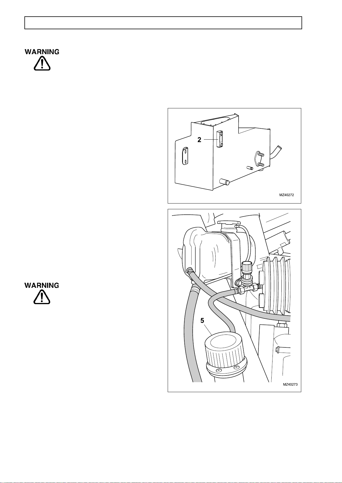
1.66
Fine jets of hydraulic fluid at high
pressure can penetrate the skin. Do
not use your fingers to check for
hydraulic fluid leaks. Do not put your
face close to suspected leaks. If
hydaulic fluid penetrates your skin
seek mecical help immediately.
HYDRAULIC LEVEL
Check
1. Position the machine on level ground.
2. Make sure all hydraulic cylinders are fully closed.
3. Stop the engine, apply the parking brake.
HYDRAULICS
4. Open the engine pod cover.
5. Check hydraulic tank sightglass (2), make sure
fluid level shows in sightglass and is above the red
line.
NOTE: Wait for two minutes, after engine is
stopped, before checking fluid level.
6 .Replenish fluid if necessary as follows:
The cap maintains an air pressure of
0.3 bar in the hydraulic tank.
7. Clean filler cap (1) and remove.
8. Top up hydraulic tank with fluid to correct level
and refit filler cap.
9. Close engine pod cover.
1. Filler cap
2. Sightglass

HYDRAULICS
HYDRAULIC TANK (1)
Removal
NOTE: Removal and installation of the hydraulic
tank is possible with the machine on the
ground.However, increasing the ground clearance
or positioning the machine over a pit will make the
operation easier and quicker.
1.67
Installation
1. Installation is the reverse of removal.
2. Use new hose clips and gaskets
3. Refer to Page 1.66 and replenish the hydraulic
tank before engine is started.
1. Position the machine over a pit, if available, or lift
on axle stands.
2. Stop the engine and chock the machine, apply
the parking brake.
3. Refer to page 1.1 and dump hydraulic pressure
then disconnect the battery.
NOTE: The hydraulic tank contains 67 litres (15 gal)
of fluid.
4. Remove the drain plug (2) and drain the hydraulic
fluid into a suitable container. Do not reuse the
hydraulic fluid unless it can be specially filtered and
tested.
5. Remove the hose clips (9) from the suction hoses
(4 & 5) of the main and auxiliary pumps and the
filler hose (3). Remove the hoses from the hydraulic
tank (1).
4. Purge the hydraulic system by starting the engine
and operating all services to fully extend and retract
cylinders several times.
5. Refer to Page 1.66, check the hydraulic level and
replenish if necessary.
6. Remove the two sightglass attachment bolts and
remove the sightglass (6).
7. Remove the screws securing the return manifold
(7) to the tank and lift the manifold to release the
gasket (8).
8. Support the hydraulic tank; remove the two nuts
from the studs and the two bolts securing the tank to
the engine and transmission sub-assembly. Lower
the tank and remove from beneath the machine.
9. Fit blanks to all openings on the tank and hoses
on the machine to prevent the ingress of dirt.
1. Hydraulic tank
2. Drain plug
3. Filler hose
4. Suction hose – auxiliary pump
5. Suction hose – main pump
6. Sightglass
7. Return manifold
8. Gasket
9. Hose clips

1.68
HYDRAULIC PUMP (LS) (2)
HYDRAULICS
Removal
NOTE: The hydraulic pump (LS) is located in the
engine compartment, attached to the gearbox.
Remove components as necessary to get access to
the pump.
1. Stop the engine and chock the machine, apply
the parking brake.
2. Refer to page 1.1 and dump hydraulic pressure
then disconnect the battery.
3. Make sure the pump is free from dirt to avoid
contamination of the hydraulic system.
4. Remove the LS hose (3) from the LS
compensator (2).
5. Remove the case drain hose (4) from the main
body of the pump (1).
6. Remove the four cap screws (6) and washers
from the pump inlet hose (5) and remove hose from
pump.
4. Refer to Page 1.66 and replenish the hydraulic
tank before the engine is started.
5. Purge the hydraulic system by starting the engine
and operating all services to fully extend and retract
cylinders several times. Refer to page 1.66, check
the hydraulic level and replenish if necessary.
7. Remove the four cap screws (8) and washers
from the two half-clamps (9) on the pump outlet
hose (7) and remove the half-clamps and hose from
pump.
8. Remove the two attachment bolts (10) and
washers securing pump to gearbox (11) and remove
pump.
9. Fit blanks to all openings on the pump and hoses
to prevent the ingress of dirt.
Installation
1. Installation is the reverse of removal.
When fitting a new LS hydraulic pump,
it is vital that the case of the pump is
filled with oil before the pump is fitted.
2. Fill the pump with 0.25 litre (0.44 pt) of oil,
through the case drain connection on the pump.
1. LS hydraulic pump
2. LS compensator
3. LS hose
4. Case drain hose
5. Inlet hose
6. Cap screw
7. Outlet hose
8. Cap screw
9. Half-clamp
10. Bolt
11. Gearbox
3. Use new O-rings when assembling the inlet and
outlet hoses, lightly lubricated with clean hydraulic
oil. Use new washers on the cap screws when
assembling the inlet and outlet hoses.

HYDRAULICS
AUXILIARY HYDRAULIC PUMP (6)
Removal
NOTE: The auxiliary hydraulic pump is located in
the engine compartment, attached to the timing
case. Remove components as necessary to get
access to the pump.
1. Stop the engine and chock the machine, apply
the parking brake.
2. Refer to page 1.1 and dump hydraulic pressure
then disconnect the battery.
3. Make sure the pump is free from dirt to avoid
contamination of the hydraulic system.
1.69
4. Remove the inlet hose (2) from the pump (1).
5. Remove the outlet hose (3) from the pump (1).
6. Remove the five cap screws and washers
securing the pump to the timing case (4) and
remove the pump.
7. Fit blanks to all openings on the pump and hoses
to prevent the ingress of dirt.
8. When a new pump is to be installed, remove the
nut (6) and washer (7) securing the drive gear (8) to
the pump shaft. Remove the drive gear and
woodruff key from the shaft.
Installation
1. Installation is the reverse of removal.
2. Use new washers (9) on the cap screws (10)
when assembling the inlet and outlet hoses.
1. Auxiliary pump
2. Inlet hose
3. Outlet hose
4. Timing case
3. Use a new gasket (5) between the pump and
timing case when installing the pump.
4. Refer to page 1.66, check the hydraulic level and
replenish if necessary before the engine is started.
5. Purge the hydraulic system by starting the engine
and operating all services to fully extend and retract
cylinders several times.
6. Check the hydraulic level and refer to Page 1.66
and replenish if necessary.
5. Gasket
6. Nut
7. Washer
8. Gear
9. Washer
10. Cap screw

1.70
FAN MOTOR (7)
NOTE: Up to Machines S/No.51200471 only.
Removal
1. Stop the engine and chock the machine, apply
the parking brake.
2. Refer to page 1.1 and dump hydraulic pressure
then disconnect the battery.
3. Open engine cover to gain access to fan motor.
4. Remove fan guard by unscrewing fasteners (1)
and lifting guard clear.
5. Disconnect the three hydraulic hoses from the
fan motor (5); blank the fan motor connections and
open hoses.
HYDRAULICS
6. Loosen the V-belt pivot fastener (2) and link arm
fasteners (3 & 4). Remove V-belt (6) from pulley
(7).
7. Remove the nut and washer (8 & 9) securing
pulley (7) to fan motor and remove pulley.
8. Remove the four bolts, washers and nuts (10, 11
& 12) securing fan motor to mounting bracket (13)
and remove fan motor.
Installation
1. Installation is the reverse of the above procedure.
2. Make sure the woodruff key is fitted to the fan
motor drive shaft before fitting the pulley.
3. Tension the V-belt and check tension using a
'Fenner' or similar tension indicator. A force of 30 N
at the mid-point on the belt should give a deflection
of 8 mm.
4. Refer to Page 1.66, check the hydraulic level and
replenish if necessary.

HYDRAULICS
FAN DRIVE BEARINGS
NOTE: Up to Machines S/No.51200471 only.
Removal
1. Stop the engine and chock the machine, apply
the parking brake.
2. Refer to page 1.1 and dump hydraulic pressure
then disconnect the battery.
3. Open engine cover to gain access to fan motor.
4. Remove the fuel sediment bowl from its bracket.
5. Remove fan guard by unscrewing bolts (1) and
lifting guard clear.
6. Loosen the V-belt pivot bolts (2) and link arm
bolts (3). Remove V-belt (4) from pulley (5).
1.71
7. Loosen the mounting bolts (6) for the radiator and
the bolts (7) beneath the fan motor and pull the
radiator forwards slightly.
8. Remove the securing bolts from the fan carrier
(8) and remove fan (9) complete with carrier.
9. Remove the setscrew (10) and washers (11 & 12)
securing pulley (5) to the hub (13). Using a suitable
puller, remove the pulley from the hub.
10. Remove the woodruff key (14) from the hub
shaft and remove the hub from hub carrier.
11. Remove circlip (15) then push out bearing (16).
Note position of spacer (17) then, using a small
punch, remove bearing (18) from carrier.
Installation
1. Installation is the reverse of the above procedure.
2. Make sure the woodruff key is fitted to the hub
shaft before fitting the pulley.
3. Make sure the spacer is fitted tbetween the
bearings before fitting the bearings.
4. Tension the V-belt and check tension using a
'Fenner' or similar tension indicator. A force of 30 N
at the mid-point on the belt should give a deflection
of 8 mm.
1. Bolt 10 Setscrew
2. Bolt 11 Washer
3. Bolt 12 Washer
4. V-belt 13 Hub
5. Pulley 14 Woodruff key
6. Bolt 15 Circlip
7. Bolt 16 Bearing
8. Carrier 17 Spacer
9. Fan 18 Bearing

1.72
FAN MOTOR (7)
NOTE: From Machines S/No.51200472 only.
Removal
1. Stop the engine and chock the machine, apply
the parking brake.
2. Refer to page 1.1 and dump hydraulic pressure
then disconnect the battery.
3. Open engine cover to gain access to fan motor
(4).
4. Remove fan guard (3) by unscrewing nuts (1) and
washers (2) and lifting clear the guard (3 ).
5. Disconnect the three hydraulic hoses from the
fan motor (4) and blank the fan motor connections
and open hoses.
HYDRAULICS
6. Loosen the four bolts (9), washers (10) and nuts,
that attach the fan motor (4) to the fan casing (8).
Remove V-belt (11) from the pulley (5).
7. Remove the nut (6) and washer (7) securing the
pulley (5) to the fan motor (4). Remove the pulley
(5).
8. Remove the four bolts (9), washers (10) and nuts,
that attach the fan motor (4) to the fan casing (8).
Remove the fan motor (4) from the machine.
Installation
1. Installation is the reverse of the above procedure.
2. Make sure the woodruff key is fitted to the fan
motor drive shaft before fitting the pulley (5).
3. Tension the V-belt (11) and check tension using a
'Fenner' or similar tension indicator. A force of 30 N
at the mid-point on the belt should give a deflection
of 8 mm.
1. Nut 7 Washer
2. Washer 8 Fan casing
3. Guard 9 Bolt
4. Fan motor 10 Washer
5. Pulley 11 V-belt
6 Nut
4. Refer to Page 1.66, check the hydraulic level and
replenish if necessary.

HYDRAULICS
FAN DRIVE BEARINGS
NOTE: From Machines S/No.51200472 only.
Removal
1. Stop the engine and chock the machine, apply
the parking brake.
2. Refer to page 1.1 and dump hydraulic pressure
then disconnect the battery.
3. Open engine cover to gain access to fan motor.
4. Remove the fuel sediment bowl from its bracket.
5. Refer to Page 1.72 and do steps 4 and 6, to
remove the fan guard and loosen and remove the
V-belt (7).
6. Remove the eight nuts and washers that secure
the fan carrier (8) to the radiator. Remove the fan
carrier (8), with the fan (14) and pulley (6)
attached.assembly attached.
1.73
7. Remove the four securing bolts (16) and washers
(15) that secure the fan (14) to the hub (13).
Remove the fan (14).
8. Remove the setscrew (4) and washer (5) securing
the pulley (6) to the hub (13). Using a suitable
puller, remove the pulley (6) from the hub (13).
9. Remove the woodruff key (12) from the hub shaft
and remove the hub (13) from hub carrier.
11. Remove circlip (9) then push out bearing (10).
Note position of spacer (11) then, using a small
punch, remove bearing (10) from carrier.
Installation
1. Installation is the reverse of the above procedure.
2. Make sure the woodruff key (12) is fitted to the
hub shaft before fitting the pulley (6).
3. Make sure the spacer (11) is fitted between the
bearings (10) before fitting the bearings.
4. Tension the V-belt (7) and check tension using a
'Fenner' or similar tension indicator. A force of 30 N
at the mid-point on the belt should give a deflection
of 8 mm.
1. Nut 9. Circlip
2. Washer 10. Brearing
3. Guard 11. Spacer
4. Bolt 12. Woodruff key
5. Washer 13. Hub
6. Pulley 14. Fan
7. V-belt 15. Washer
8. Fan carrier 16. Bolt

1.74
FAN REVERSE VALVE (72)
NOTE: From Machines S/No.51200472 only.
Removal
1. Stop the engine and chock the machine, apply
the parking brake.
2. Refer to page 1.1 and dump hydraulic pressure
then disconnect the battery.
3. Open engine cover to gain access to fan reverse
valve (2) on the air cleaner bracket.
4. Disconnect the electrical connectors to the fan
reverse valve solenoid (3) and the temperture
switch.
HYDRAULICS
5. Disconnect the five hydraulic hoses (1) from the
fan reverse valve (2) and blank the valve
connections and open hoses.
6. Remove the bolts (5) and washers (4) that attach
the fan reverse valve (2) to the air cleaner bracket.
Remove the fan reverse valve (2) from the
machine.
Installation
1. Installation is the reverse of the above procedure.
2. Refer to page 1.66, check the hydraulic level and
replenish if necessary before the engine is started.
3. Purge the hydraulic system by starting the engine
and operating the fan reverse system and all services.
Fully extend and retract cylinders several times.
4. Refer to Page 1.66. Check the hydraulic level
and replenish if necessary.
1. Hoses
2. Fan reverse valve
3. Solenoid valve
4. Washer
5. Bolt

HYDRAULICS
PARKING BRAKE VALVE (71)
NOTE: From Machines S/No.51200472 only.
Removal
1. Stop the engine and chock the machine, apply
the parking brake.
2. Refer to page 1.1 and dump hydraulic pressure
then disconnect the battery.
3. Gain access to parking brake valve (1), located
on the machine structure, adjacent to the front axle.
4. Disconnect the electrical connector to the parking
brake valve solenoid (4).
5. Disconnect the three hydraulic hoses (5) from the
parking brake valve (1) and blank the valve
connections and open hoses.
1.75
6. Remove the bolt (6), washer (3) and nut (2) that
attach the parking brake valve (1) to the structure.
Remove the parking brake valve (1) from the
machine.
Installation
1. Installation is the reverse of the above procedure.
2. Refer to page 1.66, check the hydraulic level and
replenish if necessary before the engine is started.
3. Purge the hydraulic system by starting the engine
and operating the fan reverse system and all services.
Fully extend and retract cylinders several times.
4. Refer to Page 1.66. Check the hydraulic level
and replenish if necessary.
1. Parking brake valve
2. Nut
3. Washer
4. Solenoid valve
5. Hoses
6. Bolt

1.76
HYDRAULIC FILTER (9)
Removal
NOTE: The hydraulic filter is fitted in the engine
compartment. Remove components as necessary
to get access to the filter.
1. Stop the engine and chock the machine, apply
the parking brake.
2. Refer to page 1.1 and dump hydraulic pressure
then disconnect the battery.
3. Make sure filter is free from dirt to avoid
contamination of the hydraulic system.
4. Remove the indicator lead (2) from the indicator
switch on the hydraulic filter (1).
HYDRAULICS
5. Remove the inlet hose (3) and outlet hose (4)
from the filter (1) and fit blanks to the hoses and
filter.
6. Remove the four attachment bolts (6) securing
the filter to the mounting bracket (5) and remove
the filter.
7. Fit blanks to all openings on the filter and hoses
to prevent the ingress of dirt.
Installation
1. Installation is the reverse of removal.
2. Refer to the service manual and fit a new filter
element.
3. Refer to page 1.66, check the hydraulic level and
replenish if necessary before the engine is started.
1. Hydraulic filter (9)
2. Indicator lead
3. Inlet hose
4. Outlet hose
5. Mounting bracket
6. Bolt (Qty 4)
4. Purge the hydraulic system by starting the engine
and operating all services to fully extend and retract
cylinders several times.
5. Refer to page 1.66, check the hydraulic level and
replenish if necessary.

HYDRAULICS
1.77
BRAKE VALVE (MICO) (10)
NOTE: Up to Machines S/No.51200471 only.
Operation
A single or tandem brake valve (MICO type) is fitted
to the machine, depending on model. The method
of operation is as follows:
NOTE: The single and tandem brake valve
operation is similar, the tandem design has two
spools and two sets of ports to allow for
independent operation of each system regardless of
condition of the other half.
With no force applied to the brake pedal, the valve
is in the neutral position and hydraulic system
pressure at the pressure port is blocked by the
spool, the brake pressure port is open to tank
through the tank port.
Initial application of the brake pedal moves the
spool into a position where all the ports are closed
and brake pressure has not been applied. Further
movement of the pedal moves the spool beyond the
closed position and allows pressurised fluid to flow
to the brake port. When pedal movement is
stopped, the pressure at each end of the spool
balances and fluid flow stops. If further pressure is
applied to the brake pedal the spool will allow more
fluid to pass to the brakes until the spool balances
again. Maximum brake pressure is achieved when
the brake pedal is fully depressed and the piston is
bottomed in the housing.
When the brake pedal is released, the spool moves
to close the pressure port and gradually open the
tank port to allow brake pressure to return to tank.
BRAKE VALVE (SAFIM) (10)
NOTE: From Machines S/No.51200472 only.
Operation
A single or tandem brake valve (SAFIM type) is
fitted to the machine, depending on model. The
method of operation is as follows:
NOTE: The single and tandem brake valve
operation is similar. The primary difference is that
the front and rear brakes are operated
independently of each other by separate feed and
return lines from the servo valve.
The brake pressure servo valve can be either single
or dual depending on the model of the machine.
The valve is constructed from 3 seperate modules,
the master cylinder, valve body and end plate.
Brake pedal travel and braking pressure are set
using an adjusting screw, located on the base on
the brake valve.
The operation of the servo valve is proportional to
brake pedal movement. When the brake pedal is
pressed, a pivoted lever moves a master cylinder,
which positions an associated sprung loaded plunger.
The plunger is in contact with the main shuttle valve in
the valve body. The shuttle valve controls the flow of
the pressure oil supply from the brake accumulator.
The accumulator is supplied from the inlet (PVSP)
section of the main hydraulic control valve. When the
shuttle valve is moved, the oil supply from the
accumulator is allowed to flow to the outlet connection
in the end plate, which supplies the front and rear
brakes units.
When the brake pedal is released, spring pressure in
the master valve releases pressure on the shuttle
valve and re-positions the brake pedal. The shuttle
valve moves under spring pressure to close the oil
supply from the accumulator and divert residual oil
pressure from the brake system to the hydraulic tank,
releasing the brakes.
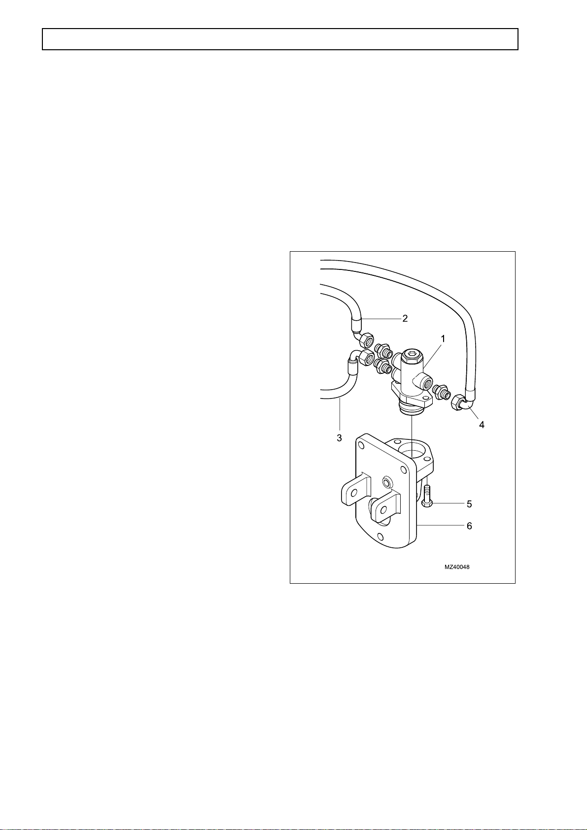
1.78
SINGLE BRAKE VALVE (MICO) (10)
HYDRAULICS
NOTE: Up to Machines S/No.51200471 only.
Removal
NOTE: The brake valve is fitted forward of the cab.
Remove the front cover and any components as
necessary to get access to the brake valve.
1. Stop the engine and chock the machine, apply
the parking brake.
2. Refer to page 1.1 and dump hydraulic pressure
then disconnect the battery.
3. Make sure brake valve is free from dirt to avoid
contamination of the hydraulic system.
4. Position a suitable container under the valve to
collect any oil spillage during removal.
5. Make sure the hoses are identified before
removal to help installation.
3. Refer to Page 1.66 and replenish the hydraulic
tank before the engine is started.
4. Bleed the brake system (refer to Page 1.95) and
test the brakes.
5. Purge the hydraulic system by starting the
engine and operating all services to fully extend and
retract cylinders several times.
6. Refer to Page 1.66, check the hydraulic level
and replenish if necessary.
6. Remove the system pressure hose (2) from
brake valve connector ‘P’.
7. Remove the return hose (3) from brake valve
connector ‘T’.
8. Remove the service hose (4) from brake valve
connector ‘A’. Take care not to lose the orifice
located in the fitting.
9. Remove the two attachment bolts (5) securing
the brake valve (1) to the mounting bracket (6) and
remove the brake valve.
10. Fit blanks to all openings on the brake valve
and hoses to prevent the ingress of dirt.
Installation
1. Installation is the reverse of removal.
2. Make sure that the spool of the brake valve is
fully out. If necessary, adjust the brake pedal
adjustment cap-screw inside the cab until the spool
of the brake valve is fully out. Then torque tighten
the cap-screw lock nut to 25-27 Nm (18-20 lbf/ft.).
1. Brake valve (10)
2. Pressure hose ‘P’
3. Return hose ‘T’
4. Service hose ‘A’
5. Bolt
6. Bracket
Torque tighten the components as follows:
Bolt (5) – 25-27 Nm (18-20 lbf/ft.)

HYDRAULICS
1.79
SINGLE BRAKE VALVE (MICO) (10) Servicing
NOTE: Up to Machines S/No.51200471 only.
Servicing is normally restricted to the replacement
of seals. When the bore of the cylinder or the piston
is scored, the brake valve must be replaced.
Dismantling
1. Make sure all the blanks are secure in the ports
then clean any dirt off the assembly before
dismantling.
2. Remove boot (20*) from piston (19).
3. Remove piston (19), springs (15**), (16), (17) and
shims (14) from housing bore.
NOTE: Some models also use a 6.35 mm (0.25 in.)
spacer with shims. Note the number of shims
removed from housing.
9. Remove O-ring (8*) and cup (10*) (note
orientation) from spacer (11). Remove O-ring (8*)
and O-rings (6*) from sleeve (7).
4. Examine bearing (18) for wear or damage, only
remove if necessary.
NOTE: Excessive wear on bearing (18) and piston
(19) require replacement.
5. Remove retainer assembly (13) from housing
bore (a ball bearing is pressed into the retainer).
6. Loosen nut (1) and remove end plug (4) from
housing. Remove spring (5), nut (1), washer (2) and
O-ring (3*) from end plug (4).
7. Use a wooden dowel to remove spacer (11),
sleeve (7) and spool (9) assembly from housing
bore.
NOTE: Take care not to scratch or mark sleeve (7)
or housing bore.Sleeve (7) and spool (9) are a
matched pair and must not be mixed with other
parts. Excessive wear on sleeve or spool will require
replacement.
8. Separate spacer (11) and spool (9) from sleeve
(7).
1. Nut 11. Spacer
2. Washer 12. Housing
3*. O-ring 13. Retainer assembly
4. End plug 14. Shim(s)
5. Spring 15.** Spring
6*. O-ring 16. Spring
7. Sleeve 17. Spring
8*. O-ring 18. Bearing
9. Spool 19. Piston
10.* Cup 20*. Boot
* Included in repair kit
** Not used in all models
NOTE: Take care not to damage cup or O-ring
grooves or bore.

1.80
SINGLE BRAKE VALVE (MICO) (10) Assembly
Use a repair kit when assembling the valve, the
repair kit contains a new cup, boot and O-rings.
Before assembly, lightly lubricate the parts from the
repair kit and the spool and sleeve with clean
hydraulic oil.
Make sure all parts are clean before assembly.
1. Install a new cup (10*) in spacer (11) and one
new O-ring (8*) on spacer (11). Note direction of
cup.
2. Install two new O-rings (6*) on large diameter end
of sleeve (7) and new O-ring (8*) on small end of
sleeve (7).
HYDRAULICS
3. Carefully install spool (9) into sleeve (7). Note
direction of spool.
4. Install sleeve (7) and spool (9) assembly into
housing bore using a wooden dowel. Note direction
of assembly. Install spring (5) into housing bore.
5. Install end plug (4) and torque load to 10.9-20.3
Nm (96-180 lbf/in.) to seat sleeves. Then loosen
end plug ¼ turn and torque load to 1.1-6.0 Nm (1060 lbf/in.). Install new O-ring (3), washer (2) and nut
(1). Hold the end plug (4) with a wrench and torque
load nut to 68.1-81.4 Nm (50-60 lbf/ft.).
6. Install retainer assembly (13) in housing.
NOTE: Depress retainer (13) until it bottoms on
spacer (11). Spool (9) and retainer (13) should
return when released. If the spool and retainer do
not return when released, the bore of sleeve (7)
may be damaged.
7. Install shim(s) (14), springs (15**), (16) and (17)
and piston (19) in housing bore.
1. Nut 11. Spacer
2. Washer 12. Housing
3*. O-ring 13. Retainer assembly
4. End plug 14. Shim(s)
5. Spring 15**. Spring
6*. O-ring 16. Spring
7. Sleeve 17. Spring
8*. O-ring 18. Bearing
9. Spool 19. Piston
10*. Cup 20*. Boot
* Included in repair kit
** Not used in all models
NOTE: Not all models use spring (15**). Some
models also use a 6.35 mm (0.25 in.) spacer with
shims. Make sure the same number of shims and
the spacer, that were removed during dismantling,
are installed.
8. Install new boot (20*) on housing.
9. Test the brake pressure at service hose A on
brake valve. Pressure can be adjusted by adding or
removing shims (14) to retainer assembly (13).

HYDRAULICS
1.81
SINGLE BRAKE VALVE (SAFIM) (10)
NOTE: From Machines S/No.51200472 only.
Removal
NOTE: The brake valve is fitted forward of the cab.
Remove the front cover and any components as
necessary to get access to the brake valve.
1. Stop the engine and chock the machine, apply
the parking brake.
2. Refer to page 1.1 and dump hydraulic pressure
then disconnect the battery.
3. Make sure brake valve is free from dirt to avoid
contamination of the hydraulic system.
4. Position a suitable container under the valve to
collect any oil spillage during removal.
3. Bleed the brake system (refer to Page 1.95) and
test the brakes. If necessary, adjust the brake
pressure by connecting a pressure gauge to test
point 68 and apply the brakes. Adjust the brake
pressure by altering the position of brake pedal
travel with the adjuster screw (2).
4. Refer to Page 1.66 and replenish the hydraulic
tank, before the engine is started.
5. Purge the hydraulic system by starting the
engine and operating all services to fully extend
and retract cylinders several times.
6. Refer to Page 1.66, check the hydraulic level
and replenish if necessary.
5. Make sure the hoses are identified to help
installation. Disconnect the three hoses (1) from
the valve (10).
7. Remove the two protective caps (3) from the
brake pedal attachment bolt (4). Remove the nut
(8) and bolt (4) and remove the brake pedal (5).
8. Fit blanks to all openings on the brake valve and
hoses to prevent the ingress of dirt.
9. Remove the four cap screws (7) from the base
plate (6).
12. Remove the brake valve assembly (10) from
the machine.
Installation
1. Installation is the reverse of removal.
2. If necessary, adjust the brake pedal angle by
adjusting the threaded peg (9) under the brake
pedal (10). Once adjusted, tighten the peg lock
nut.

1.82
SINGLE BRAKE VALVE (SAFIM) -Servicing
NOTE: From Machines S/No.51200472 only.
Servicing is normally restricted to the replacement of
seals in the brake master and brake valve modules of
the valve assembly. When any cylinder bore or sliding
contact surface is scored, the brake valve must be
replaced.
Dimantling (General)
NOTE: During intial dismantling, make sure all items
are noted and kept with the correct part of the brake
valve.
1. Make sure all the blanks are secure in the ports then
clean any dirt off the assembly before dismantling.
HYDRAULICS
2. Loosen the two screws (1) sufficient to remove
the end plate (2) and brake valve module (3) from
the brake master module (4).
3. Carefully, as an assembly, remove the end plate
(2) and brake valve module (3), with the two screws
(1), from the brake master module (4).
4. Carefully remove the two screws (1) and seperate
the end plate (2) from the brake valve module (3).
Assembly (General)
1. Installation is the reverse of removal.
2. If necessary, adjust the brake pedal angle/brake
pressure (refer to brake valve installation procedure
at Page 1.81).
1. Screws
2. End plate
3. Brake valve module
4. Brake master module

HYDRAULICS
SINGLE BRAKE VALVE (SAFIM)-Servicing
1.83
NOTE: From Machines S/No.51200472 only.
Servicing is normally restricted to the replacement of
seals in the brake master and brake valve modules of
the valve assembly. When any cylinder bore or sliding
contact surface is scored, the brake valve must be
replaced.
Dismantling (Brake Master Module)
1. Remove the grub screw (2) that secures the
pedal pivot pin (5) in position. Carefully drift out the
pedal pivot pin (5) from the pedal base and extract
the pedal lever (1) and cover (3).
2. Remove the end plug (4) from the brake master
module (19).
3. Extract the valve cylinder (17) from the brake
master module (19).
3. Before assembly, lightly lubricate the parts from
the repair kit and the spool and sleeve with clean
hydraulic oil.
4. Make sure all parts are clean before assembly.
4. Remove the circlip (15) from the brake master
module (19).
5. Carefully extract the O-seal (13), valve assembly
and gland seal (18) from the brake master module
(19).
6. Remove the plug (7) and washer (6) from the
brake master module (19).
7. Remove the adjuster (8) and nut (9) from the
brake master module (19).
8. Remove the screw (10) and pin (12) from the
valve assembly. Seperate the the two end plates
(14) and (16) and three springs (11) of the valve
assembly.
9. Clean and examine the valve assemby parts and
bore, pedal pivot pin (5) and pivot points of the
brake master module (19).
Assembly (Brake master module)
1. Installation is the reverse of the removal.
2. Make sure a new gland seal (18) and O-ring seal
(13) are fitted.
1. Pedal lever
2. Grub screw
3. Cover
4. End plug
5. Pivot pin
6. Plug
7. Washer
8. Adjuster
9. Nut
10. Screw
11. Springs
12. Pin
13. O-ring seal
14. End plate
15. Circlip
16. End plate
17. Valve cylinder
18. Gland seal
19. Brake master module

1.84
SINGLE BRAKE VALVE (SAFIM) -Servicing
NOTE: From Machines S/No.51200472 only.
Servicing is normally restricted to the replacement of
seals in the brake master and brake valve modules of
the valve assembly. When any cylinder bore or sliding
contact surface is scored, the brake valve must be
replaced.
Dismantling (Brake Valve Module)
1. Remove the spring (8) and shuttle valve (7) and
O-seal (6) from the brake valve module (9).
2. Remove the four O-seals (10) from the brake
valve module (9).
HYDRAULICS
3. Remove the grub screw (5) from the brake valve
module (9).
3. Remove the circlip (1) and extract the plug (11),
sealing ring (2) and seal (3), valve (10) and spring
(4) from the brake valve module (9).
4. Clean and examine the valve module (9), valve
(4), shuttle vale (7) and plug (11).
Assembly (Brake valve module)
1. Installation is the reverse of removal.
2. Make sure a new sealing ring (2) and O-ring
seals (10), (2) and (6) are fitted.
3. Before assembly, lightly lubricate the parts from
the repair kit and the spool and sleeve with clean
hydraulic oil.
4. Make sure all parts are clean before assembly.
1. Circlip
2. Sealing ring
3. Seal
4. Spring
5. Grub screw
6. O-ring seal
7. Shuttle valve
8. Spring
9. Brake valve module
10. O-ring seal
11. Plug

HYDRAULICS
DUAL BRAKE VALVE (MICO) (10)
1.85
NOTE: Up to Machines S/No.51200471 only.
Removal
NOTE: The brake valve is fitted forward of the cab.
Remove the front cover and any components as
necessary to get access to the brake valve.
1. Stop the engine and chock the machine, apply the
parking brake.
2. Refer to page 1.1 and dump hydraulic pressure
then disconnect the battery.
3. Make sure brake valve is free from dirt to avoid
contamination of the hydraulic system.
4. Position a suitable container under the valve to
collect any oil spillage during removal.
5. Make sure the hoses are identified before removal
to help installation.
4. Bleed the brake system (refer to Page 1.95) and
test the brakes.
5. Purge the hydraulic system by starting the engine
and operating all services to fully extend and retract
cylinders several times.
6. Refer to Page 1.66, check the hydraulic level and
replenish if necessary.
6. Remove the two system pressure hoses (2) and (
3) from brake valve connectors ‘P’.
7. Remove the two return hoses (4) and (5) from brake
valve connectors ‘T’.
8. Remove the two service hoses (6) and (7) from
brake valve connectors ‘A’.
9. Remove the two attachment bolts (8) securing the
brake valve (1) to the mounting bracket (9) and
remove the brake valve.
10. Fit blanks to all openings on the brake valve and
hoses to prevent the ingress of dirt.
Installation
1. Installation is the reverse of removal.
2. Make sure that the spool of the brake valve is fully
out. If necessary, adjust the brake pedal adjustment
cap-screw inside the cab until the spool of the brake
valve is fully out. Then torque tighten the cap-screw
lock nut to 25-27 Nm (18-20 lbf/ft.).
1. Brake valve (10)
2. Pressure hose ‘P’
3. Pressure hose ‘P’
4. Return hose ‘T’
5. Return hose ‘T’
6. Service hose ‘A’
7. Service hose ‘A’
8. Bolt
9. Bracket
Torque tighten the components as follows:
3. Refer to Page 1.66 and replenish the hydraulic tank
before the engine is started.
Bolt (8) – 25-27 Nm (18-20 lbf/ft.)

1.86
DUAL BRAKE VALVE (MICO) - Servicing
HYDRAULICS
NOTE: Up to Machines S/No.51200471 only.
Servicing is normally restricted to the replacement of
seals. When the bore of the cylinder or the piston is
scored, the brake valve must be replaced.
Dismantling
1. Make sure all the blanks are secure in the ports
then clean any dirt off the assembly before
dismantling.
2. Remove boot (23*) from piston (22).
3. Remove piston (22), springs (18**), (19), (20) and
shims (17) from housing bore.
NOTE: Some models also use a 6.35 mm (0.25 in.)
spacer with shims. Note the number of shims removed
from housing.
4. Examine bearing (21) for wear or damage, only
remove if necessary.
9. Remove O-ring (10*) and cup (13*) (note
orientation) from spacer (14). Remove O-ring (10)
from sleeve (11) and O-rings (7*) from sleeve (8).
NOTE: Take care not to damage cup or O-ring grooves
or bore.
NOTE: Excessive wear on bearing (21) and piston (22)
require replacement.
5. Remove retainer assembly (18) from housing bore
(a ball bearing is pressed into the retainer).
6. Loosen nut (1) and remove end plug (4) from
housing. Remove spring (6), retainer (5), nut (1),
washer (2) and O-ring (3*) from end plug (4).
7. Use a wooden dowel to remove spacer (14),
sleeves (8) and (11) and spools (9) and (12)
assembly from housing bore. This assembly must be
removed through end plug (4) end of housing.
NOTE: Take care not to scratch or mark sleeves (8) and
(11) or housing bore. Sleeve (8) and spool (9) also
sleeve (11) and spool (12) are matched pairs and must
not be mixed with other parts. Excessive wear on sleeve
or spool will require replacement.
8. Separate spacer (14) and spools (9) and (12) from
sleeves (8) and (11).
 Loading...