

Page 1

Liner 3000 with Communicator
Technical Systems
Electric System /
Hydraulic System
Page 2

Page 3

TIC Liner 3000 with Communicator Electric System
Contents Electric System
CCU – Claas Control Unit.............................................................................................. ZE-2
Pin assignment in modules.......................................................................................... ZE-10
01a - Main power supply- Circuit diagram with
„Basic tractor equipment“ retrofit kit (ISO socket) .............................................01a-2
01b - Main power supply- Circuit diagram without
„Basic tractor equipment“ retrofit kit (2-pin power supply socket) .....................01b-2
05a - Terminal............................................................................................................05a-2
06a - CAN bus, power supply of modules Circuit diagram with „Basic tractor
equipment“ retrofit kit (ISO socket) ...................................................................06a-2
06b - CAN bus, power supply of modules Circuit diagram without
„Basic tractor equipment“ retrofit kit (2-pin power supply socket) .....................06b-2
07a - Chassis transport and working position ............................................................07a-2
08a - Turning area circuit...........................................................................................08a-2
10a - Raking height adjustment .................................................................................10a-2
11a - Raising and lowering the rotor arms .................................................................11a-2
13a - Adjusting the front rotor working width..............................................................13a-2
26a - Machine monitoring ..........................................................................................26a-2
Index ....................................................................................................................... Index-3
Page 4

Electric System Liner 3000 with Communicator TIC
Page 5

CCU – Claas Control Unit
Page 6
Electric System Liner 3000 with Communicator TIC
CCU – Claas Control Unit
ZE-2 Lin-e-ze 12/03
Page 7

TIC Liner 3000 with Communicator Electric System
Key to diagram:
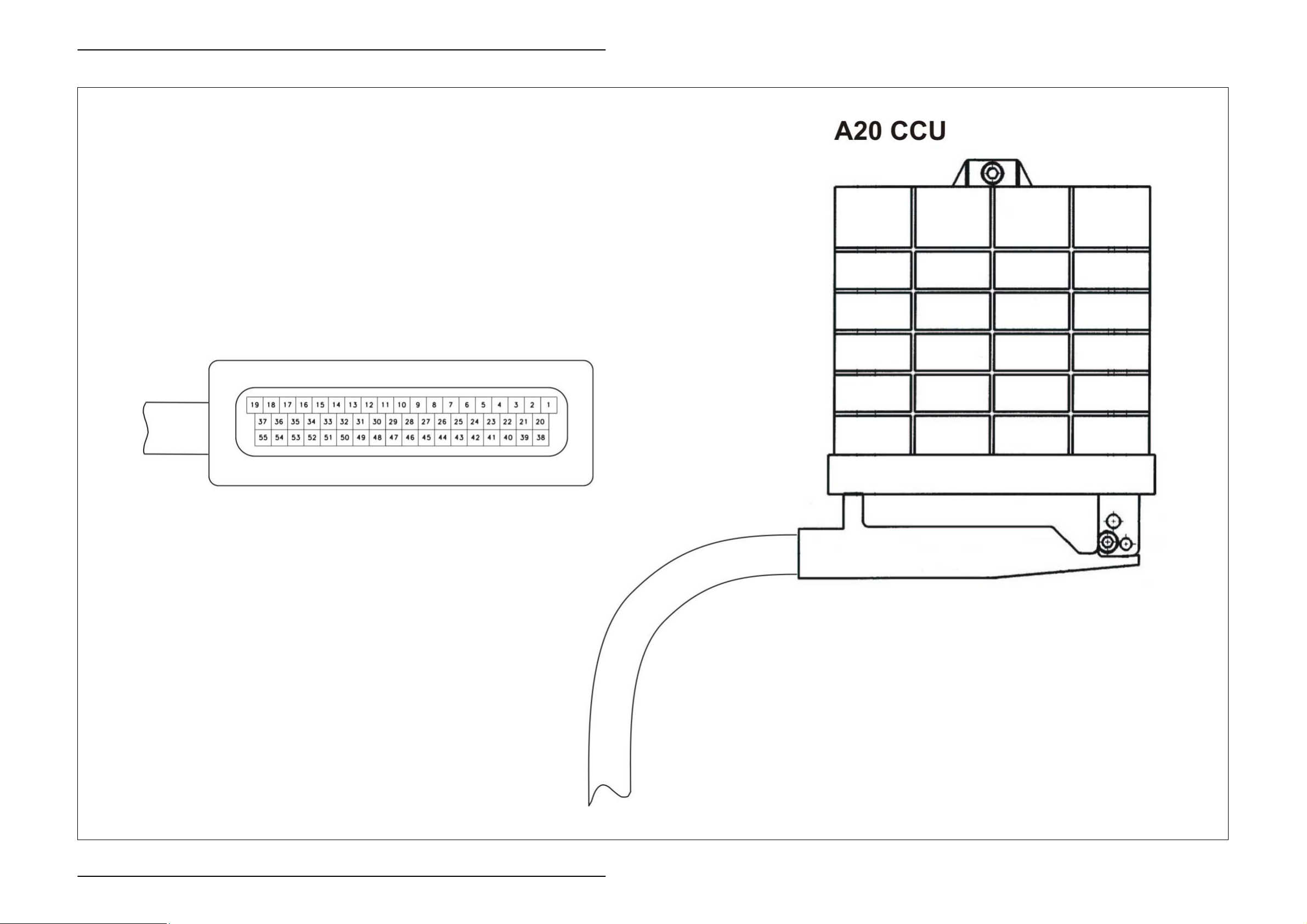
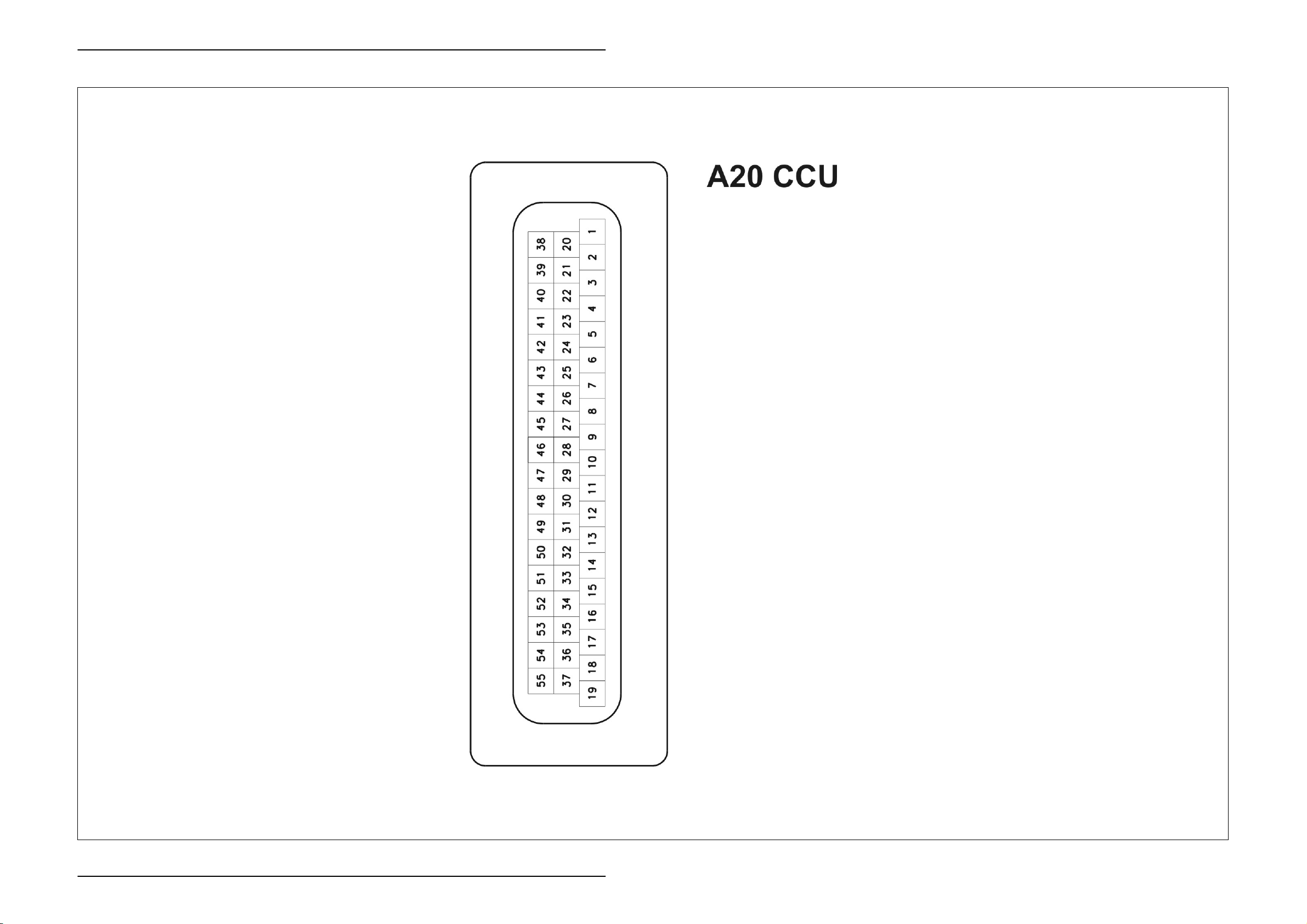
A20 CCU Module
12/03 Lin-e-ze ZE-3
Page 8

Electric System Liner 3000 mit Communicator TIC
ZE-4 Lin-e-ze 12/03
Page 9

Pin assignment in modules
Page 10
Electric System Liner 3000 with Communicator TIC
Pin assignment in modules
ZE-10 Lin-e-ze 12/03
Page 11
TIC Liner 3000 with Communicator Electric System
A20 CCU module
Pin Function Component Measuring
1 Power earth 31 Earth Input 6
2 Wheel revolution connector - - - 8
3 Not used - - - -
4 Offset correction of rotor position
sensors
5 Electronics plus +30/E 12 V Input 6
6 Not used - - - -
7 Not used - - - -
8 Temperature connector - - - 26
9 Not used - - - -
10 Not used - - - -
11 Not used - - - -
12 Power supply of rotor position sensors B121 12 V Output 8
13 Signal input B121-1 PWM. 5-95% Input 8
14 Signal input B121-3 PWM. 5-95% Input 8
15 Not used - - - -
16 Not used - - - -
17 CAN low - - - 6
18 Not used - - - -
19 Electronics earth XD pin 7 32 Earth Input 5
20 Drive speed B9 Earth frequency Input 8
21 Chassis position Z99 Earth Input 7
22 Lower rotor height adjustment V16-1 5 V Output 10
23 Switch on electronic unit +15/T12 12 V Input 6 and 1
24 Diagnosis plug XD pin 1 XD Boot signal Input 5
25 Not used - - - -
26 Not used - - - -
27 Not used - - - -
28 Not used - - - -
29 Not used - - - -
30 Not used - - - -
31 Temperature connector - - - 26
32 Signal input B121-2 PWM. 5-95% Input 8
33 Signal input B121-4 PWM. 5-95% Input 8
34 Not used - - - -
35 Not used - - - -
36 CAN high - - - 6
37 Not used - - - -
38 Power plus +30/P 12 V Input 7, 10, 11, 13
39 Power plus +30/P 12 V Input 7, 10, 11, 13
40 Electronics plus +30/E 12 V Input 6
Direction Circuit
variable
V16-2 5 V Output 8
diagram no.
12/03 Lin-e-ze ZE-11
Page 12

Electric System Liner 3000 with Communicator TIC
A20 CCU module
Pin Function Component Measuring
variable
41 Raise rotor height adjustment Y157 12 V Output 10
42 Increase working width Y162 12 V Output 13
43 Decrease working width Y163 12 V Output 13
44 Lower chassis Y159 12 V Output 7
45 Raise chassis Y158 12 V Output 7
46 Raise rear right rotor Y160 12 V PWM Output 11
47 Raise rear left rotor Y161 12 V PWM Output 11
48 Lower rear right rotor Y169 12 V PWM Output 11
49 Lower rear left rotor Y168 12 V PWM Output 11
50 CAN bus socket (7-pin) XD pin 2 serial
XD Data - 5
interface
51 CAN bus socket (7-pin) XD pin 3 serial
XD Data - 5
interface
52 Lower front left rotor Y166 12 V PWM Output 11
53 Lower front right rotor Y164 12 V PWM Output 11
54 Raise front left rotor Y167 12 V PWM Output 11
55 Raise front right rotor Y165 12 V PWM Output 11
Direction Circuit
diagram no.
Circuit diagram assignment
of fuses and relays
Component Designation Circuit Diagram
F1.1 5 A fuse 1a, 1b
F1.2 25 A fuse 1a, 1b
F2 1A fuse (basic tractor equipment) 1a
F3 60 A fuse (basic tractor equipment) 1a
F4 25 A fuse (basic tractor equipment) 1a
V16-1 Amplifier 10
V16-2 Amplifier 8
E-12 Lin-e-ze 12/03
Page 13
1a
Main power supply
Liner 3000 with Communicator
Circuit diagram with „Basic tractor equipment“ retrofit kit
(ISO socket)
Page 14
Electric System Liner 3000 with Communicator TIC
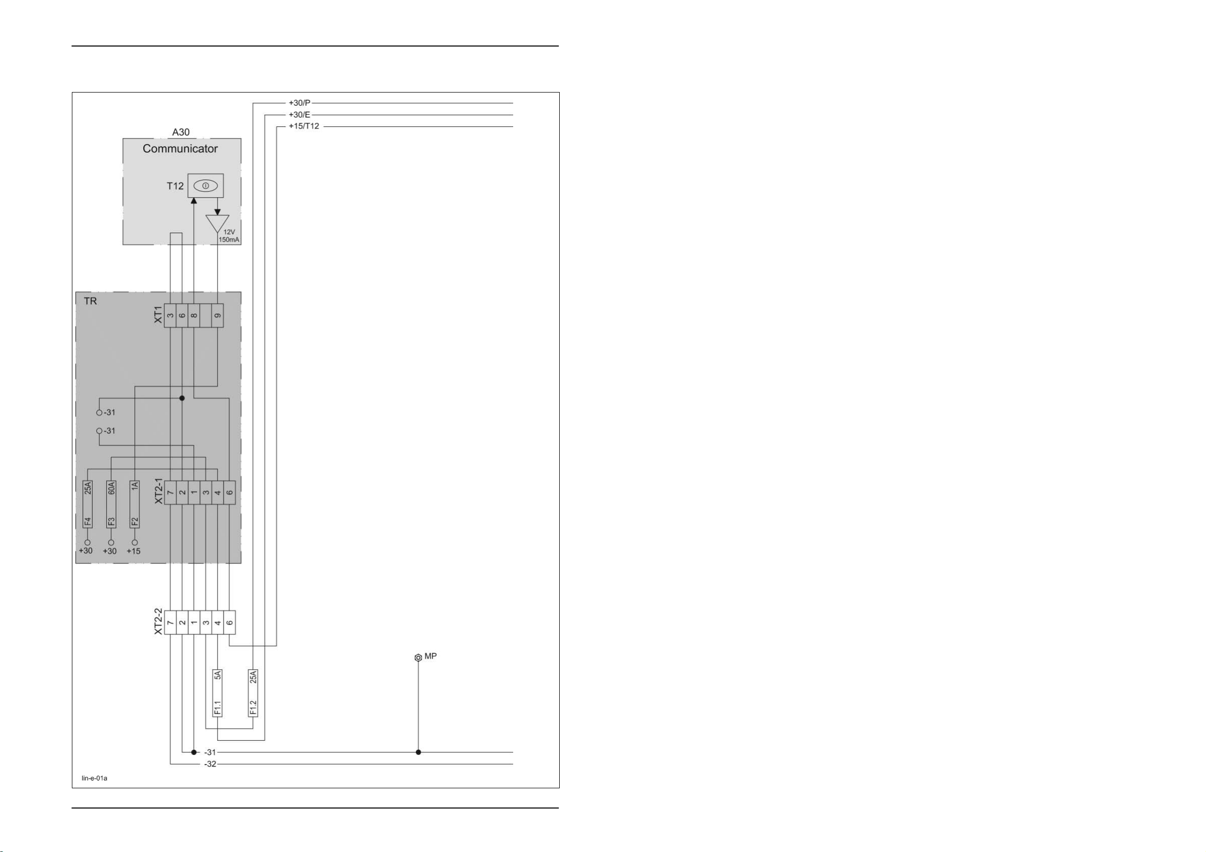
01a - Main power supply -
Circuit diagram with „Basic tractor equipment“ retrofit kit (ISO socket)
Key to diagram:
A30 Terminal
F2 1 A fuse
F3 60 A fuse
F4 25 A fuse
F1.1 5 A fuse
F1.2 25 A fuse
MP Earth point
TR Basic tractor equipment
(tractor retrofit kit according to ISO standard)
T12 Main switch
XT1 Terminal connector
XT2-1 Tractor connector, 9-pin (acc. to ISO standard)
XT2-2 Implement connector, 9-pin (acc. to ISO standard)
+30/P Potential, power plus
+30/E Potential, electronics plus
-31 Potential, power earth
-32 Potential, electronics earth
1a-2 Lin-01-el. 12/03
Page 15

TIC Liner 3000 with Communicator Electric System
Description of function:
TR Basic tractor equipment Before using the implement, the basic tractor equipment wiring loom must
be fitted. The tractor is now equipped with a standardized (ISO) socket.
Please refer to the Operator's Manual for further information.
Main power supply Power supply from the tractor is via the (ISO) socket connector XT1-1,
XT1-2.
Potential + 30/P The potential + 30/P (battery power plus) is safeguarded with 25 A by fuse
F1.2 at the implement.
Potential + 30/E The potential + 30/E (battery electronic plus) is safeguarded with 5 A by
fuse F1.1 at the implement.
Potential + 15/T12 This potential is switched by the tractor potential 15 (ignition plus) and by
the main switch T12 at terminal A30 and serves for switching on the
electronic unit.
Note: When switching the ignition off, the electronic unit of the
implement is also shut down.
12/03 Lin-01-el. 1a-3
Page 16
Electric System Liner 3000 with Communicator TIC
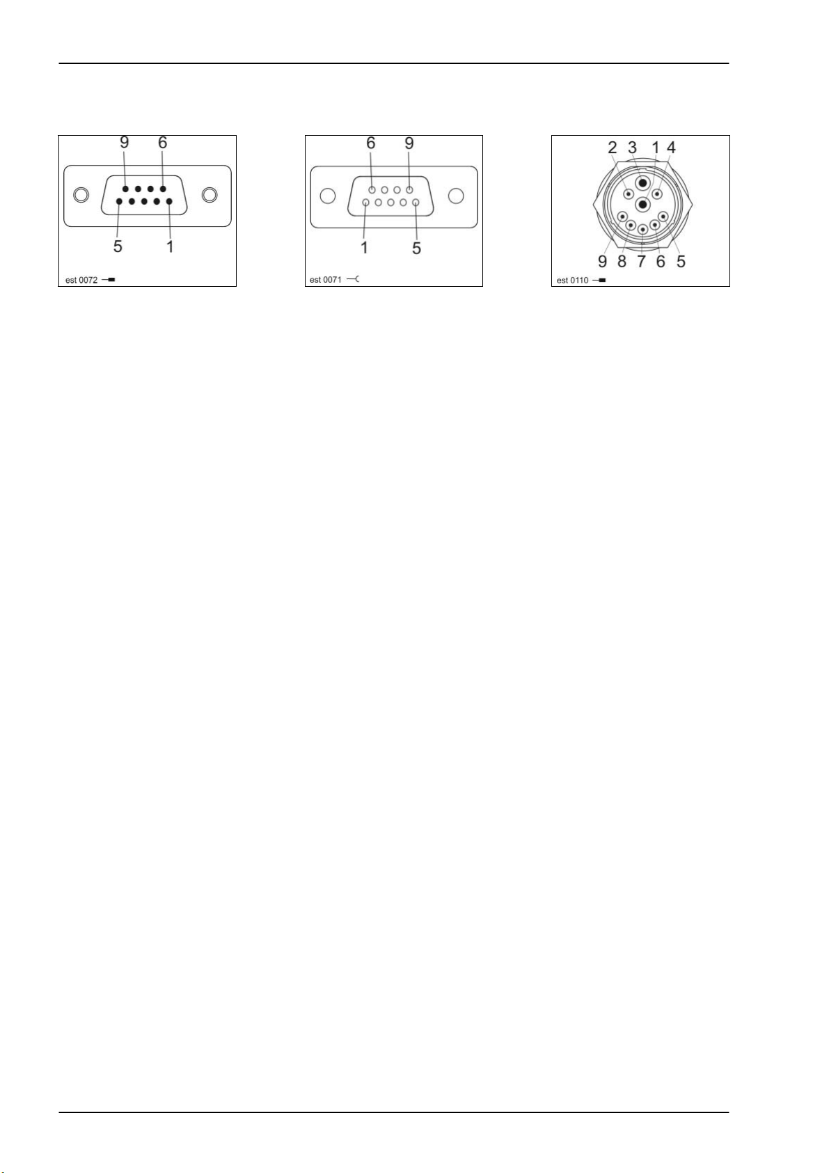
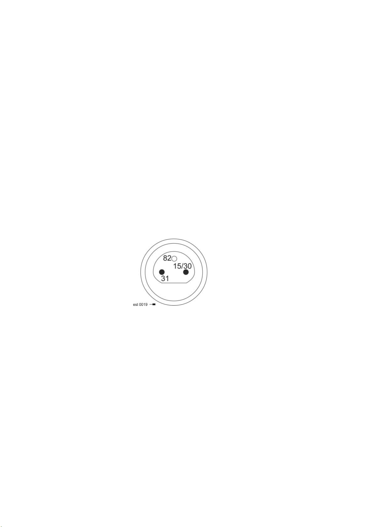
Connector pin definition:
Connector XT1 Socket XT1 Connector XT2-1 XT2-2
1a-4 Lin-01-el. 12/03
Page 17

1b
Main power supply
Liner 3000 with Communicator
Circuit diagram without
„Basic tractor equipment“ retrofit kit
(2-pin power supply socket)
Page 18

Electric System Liner 3000 with Communicator TIC
01b - Main power supply-
Circuit diagram without „Basic tractor equipment“ retrofit kit (2-pin power supply socket)
Key to diagram:
A30 Terminal
F1.1 5 A fuse
F1.2 25 A fuse
MP Earth point
T12 Main switch
XT1 Terminal connector
XT2 Implement connector, 9-pin (acc. to ISO standard)
XV Power supply connector
+30/P Potential, power plus
+30/E Potential, electronics plus
-31 Potential, power earth
-32 Potential, electronics earth
1b-2 Lin-01-el. 12/03
Page 19

TIC Liner 3000 with Communicator Electric System
Description of function:
Main power supply Power supply from the tractor is via the XV connector.
Potential + 30/P The potential + 30/P (battery power plus) is safeguarded with 25 A by fuse
F1.2 at the implement.
Potential + 30/E The potential + 30/E (battery electronic plus) is safeguarded with 5 A by
fuse F1.1 at the implement.
Potential + 15/T12 This potential is switched the main switch T12 at terminal A30 and serves
for switching on the electronic unit.
Note: To avoid tractor battery discharge during extended breaks, the
electronic unit of the implement should be shut down using the
main switch T12 on terminal A30.
12/03 Lin-01-el. 1b-3
Page 20
Electric System Liner 3000 with Communicator TIC
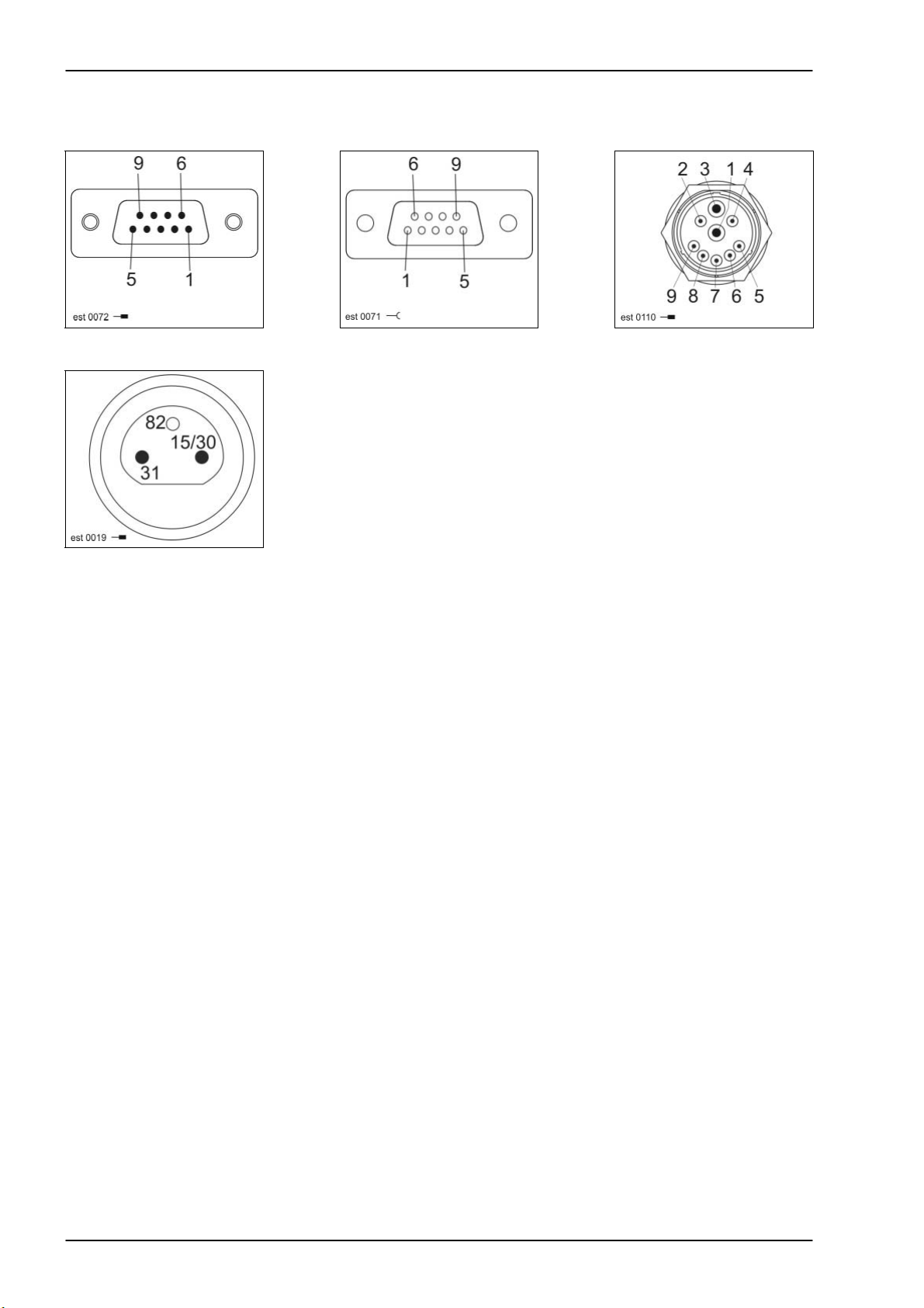
Connector pin definition:
Connector XT1 Socket XT1 Connector XT2
Connector XV
1b-4 Lin-01-el. 12/03
Page 21

5a
Terminal
Liner 3000 with Communicator
Page 22

Electric System Liner 3000 with Communicator TIC
05a - Terminal
Key to diagram:
A20 CCU module
CAN_
END
V18 Active CAN bus termination
XD CAN bus socket (7-pin)
Wiring loom connector
5a-2 Lin-05-el. 12/03
Page 23

TIC Liner 3000 with Communicator Electric System
Description of function:
Terminal The XD connector serves for diagnosis with the CDS CLAAS Diagnosis
system.
12/03 Lin-05-el. 5a-3
Page 24
Electric System Liner 3000 with Communicator TIC
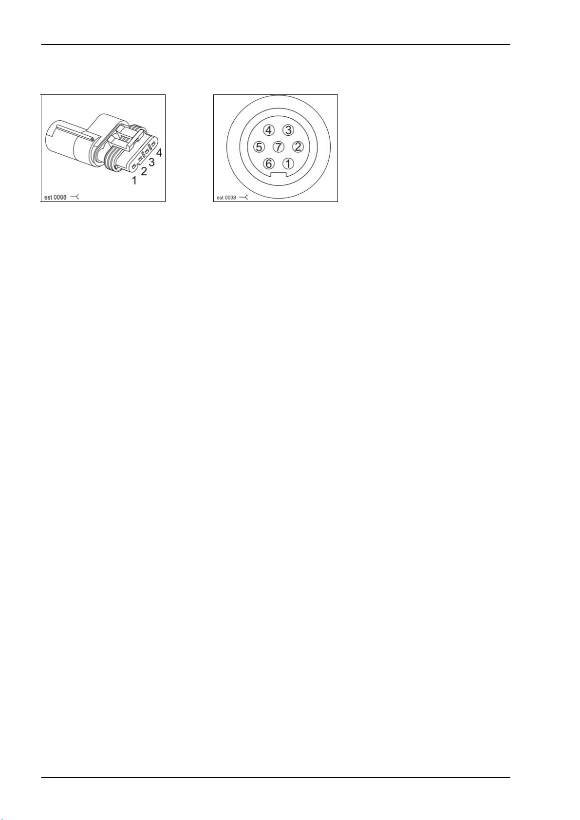
Connector pin definition:
Connector CAN_END Socket XD
5a-4 Lin-05-el. 12/03
Page 25

6a
CAN bus, power supply of modules
Liner 3000 with Communicator
Circuit diagram with
„Basic tractor equipment“ retrofit kit
(ISO socket)
Page 26

Electric System Liner 3000 with Communicator TIC
06a - CAN bus, power supply of modules
Circuit diagram with „Basic tractor equipment“ retrofit kit (ISO socket)
Key to diagram:
A20 CCU module
A30 Terminal
XT1 Terminal connector
XT2-1 Tractor connector, 9-pin (acc. to ISO standard)
XT2-2 Implement connector, 9-pin (acc. to ISO standard)
6a-2 Lin-06-el. 12/03
Page 27

TIC Liner 3000 with Communicator Electric System
Description of function:
The performance data (operating hours, ...) are stored in module A 20.
Communication of the module with the CCT terminal A30 is via the
CAN bus.
12/03 Lin-06-el. 6a-3
Page 28

Electric System Liner 3000 with Communicator TIC
Connector pin definition:
Connector XT1 Socket XT1 Connector XT2-1, XT2-2
6a-4 Lin-06-el. 12/03
Page 29
6b
CAN bus, power supply of modules
Liner 3000 with Communicator
Circuit diagram without
„Basic tractor equipment“ retrofit kit
(2-pin power supply socket)
Page 30
Electric System Liner 3000 with Communicator TIC
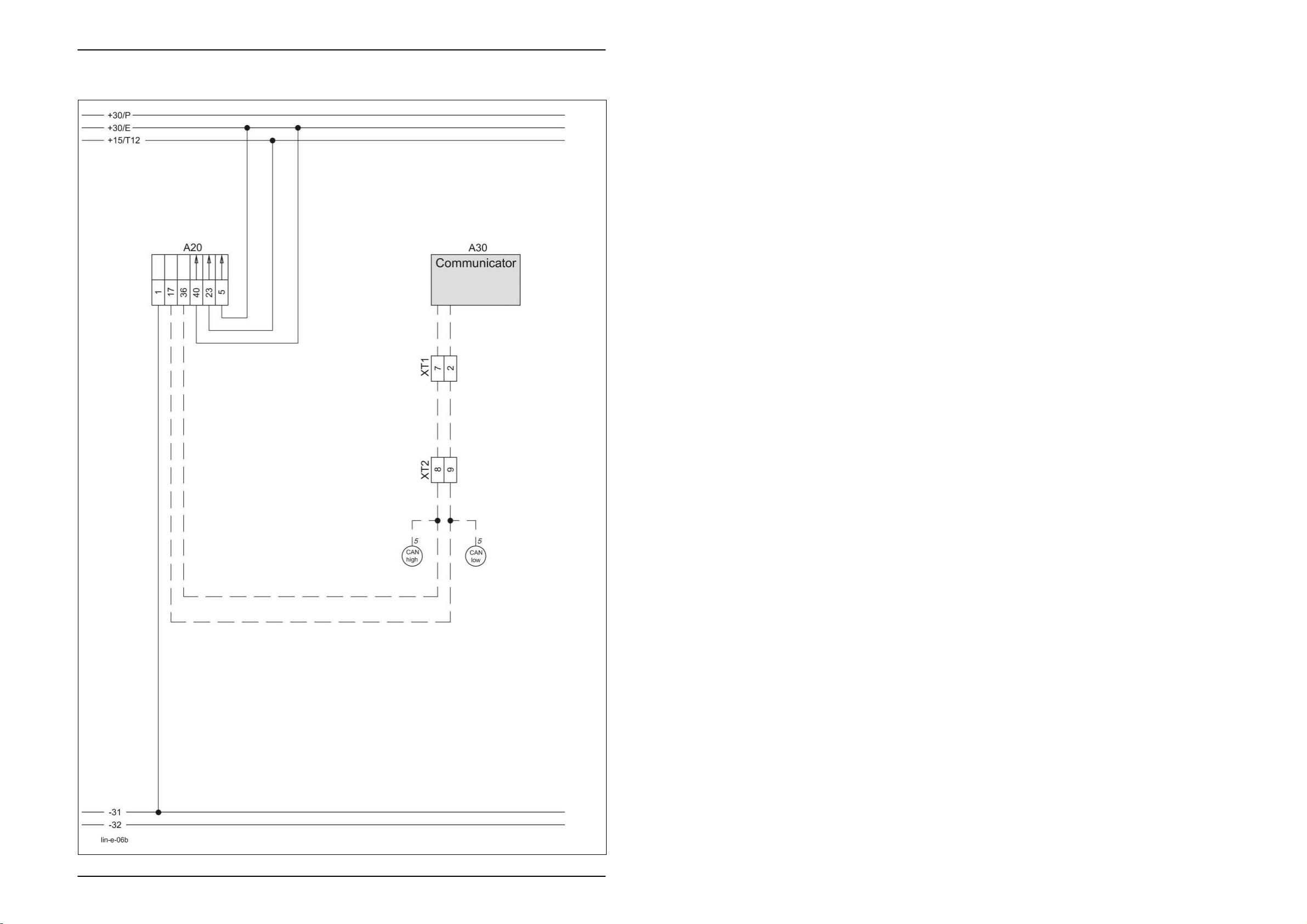
06b - CAN bus, power supply of modules
Circuit diagram without „Basic tractor equipment“ retrofit kit (2-pin power supply socket)
Key to diagram:
A20 CCU module
A30 Terminal
XT1 Terminal connector
XT2 Tractor connector, 9-pin (acc. to ISO standard)
6b-2 Lin-06-el. 12/03
Page 31

TIC Liner 3000 with Communicator Electric System
Description of function:
The performance data (operating hours, ...) are stored in module A 20.
Communication of the module with the CCT terminal A30 is via the
CAN bus.
12/03 Lin-06-el. 6b-3
Page 32

Electric System Liner 3000 with Communicator TIC
Connector pin definition:
Connector XT1 Socket XT1 Connector XT2
6b-4 Lin-06-el. 12/03
Page 33

7a
Chassis transport and working
position
Liner 3000 with Communicator
Page 34

Electric System Liner 3000 with Communicator TIC
07a - Chassis transport and working position
Key to diagram:
A20 CCU module
Axle Wiring loom connector
MV9 Wiring loom connector
MV10 Wiring loom connector
Y158 Raise chassis solenoid coil
Y159 Lower chassis solenoid coil
Z99 Chassis position actual value switch
Measured value table:
Item Component Measured value Remark
Y158
Y159
Z99 Chassis position
Solenoid coil 3.8 A
3.2 Ω
1 – 0 (Earth signal) Reed contact
actual value switch
See inscription
7a-2 Lin-07-el. 12/03
Page 35

TIC Liner 3000 with Communicator Electric System
Description of function:
Module A 20 actuates the corresponding solenoid coils Y 158 and Y159
for raising and lowering the chassis.
This is done automatically with the program "Approach working position /
Transport position" or using the "Manual operation" function.
Working position = chassis raised
Transport position = chassis lowered.
Secondary chassis raise When the turning area circuit is running, the Chassis raise solenoid coil
(Y158) is actuated for 2 seconds in parallel with lowering of the rotors.
This keeps the chassis from lowering when in the working position due to
a possible leak.
Chassis position The chassis position switch (Z99) transmits a signal to the electronic unit
when the chassis is raised.
If the chassis position is not detected in the "Approach working position"
and "Reset basic values" programs, the automatic functions are aborted.
Adjustment of sensors The chassis position switch (Z99) is set to a clearance of 4 mm from the
signal magnet with the chassis raised.
In this position, the signal magnet and the sensor should not be centred
opposite each other, but slightly offset.
12/03 Lin-07-el. 7a-3
Page 36

Electric System Liner 3000 with Communicator TIC
Connector pin definition:
Socket MV9, MV10 Axle connector
7a-4 Lin-07-el. 12/03
Page 37

8a
Turning area circuit
Liner 3000 with Communicator
Page 38

Electric System Liner 3000 with Communicator TIC
08a - Turning area circuit
Key to diagram:
A20 CCU Module
B9 Drive speed sensor
B121-1 Rotor position sensor, front left
B121-2 Rotor position sensor, front right
B121-3 Rotor position sensor, rear left
B121-4 Rotor position sensor, rear right
D1-4 Diode component
V16-2 Amplifier
S-LV Wiring loom connector
S-RV Wiring loom connector
S-LH Wiring loom connector
S-RH Wiring loom connector
Wheel
rev.
Wiring loom connector
Measured value table:
Item Component Measured value Remark
B121 Rotor position
sensors
B121 Rotor position
sensors
B6 Drive sensor 1 – 0 earth signal Metal is detected
Approx. 5% PWM
signal
Approx. 95% PWM
signal
Cylinder retracted
Cylinder extended
by sensor or not.
Lin-08-el. 12/03
8a-2
Page 39

TIC Liner 3000 with Communicator Electric System
Description of function:
To control the automatic functions, the electronic unit monitors:
- the drive speed
- the position of the rotor arms' hydraulic cylinders
Rotor position sensors B121 The rotor position sensors are integrated in the hydraulic cylinders as
contactless position measuring sensors.
A spindle with a steep thread inside the hydraulic cylinders rotates a
signal generator.
The angle of rotation between the retracted and the extended cylinder
position is < 360°.
The signal generator emits a magnetic field to the sensor electronic unit
located opposite of it. The position of the magnetic field which
corresponds to the hydraulic cylinder position is detected by the sensor
electronic unit.
The sensor electronic unit transmits a pulse-width modulated signal
(PWM, corresponding to the hydraulic cylinder position) to module A 20.
With the hydraulic cylinder retracted, this signal is 5% and with the
cylinder extended, it is 95% PWM.
See also the Technical Systems / Hydraulic system documentation.
Offset of rotor position
sensors B 121
The position "Hydraulic cylinder retracted" must be programmed in the
sensor electronic unit (= sensor offset).
This programming changes when the ram rod of a hydraulic cylinder is
rotated, e.g. during service work.
For offset programming, the sensor signal output must be connected to
the 12 V sensor supply voltage for at least 2 seconds.
The CCU module carries out this offset programming during each basic
initialisation. This is done by the diode component D.1-4 and amplifier
V16-2.
This is detected at terminal A30. When the basic initialisation is carried
out, a cylinder position of 100% and then of 5% is displayed for a short
time when in transport position (cylinder retracted).
When a hydraulic cylinder position which is illogical to the electronic unit is
detected, e.g. due to service work, an error is reported.
In order to remove the error, the operator may move to transport position
or carry out a basic initialisation.
The PWM signal from sensors B121 is also displayed as cylinder position
on terminal A30. This involves slight deviations:
90% signal change = 100% change of display on terminal A30.
Approach transport position
program
If the drive sensor B9 detects a signal change (universal drive shaft is
rotating), approaching the transport position in automatic mode is not
possible.
Adjustment of
drive sensor B9
Sensor B9 is set to a clearance of 3-4 mm from the outside profile of the
drive shaft.
12/03 Lin-08-el.
08a-7
Page 40

Electric System Liner 3000 with Communicator TIC
Connector pin definition:
Connector B9
Socket B121, wheel rev.
Relay socket V16-2
Lin-08-el. 12/03
8a-4
Page 41

10a
Raking height adjustment
Liner 3000 with Communicator
Page 42

Electric System Liner 3000 with Communicator TIC
10a - Raking height adjustment
Key to diagram:
A20 CCU module
V16-1 Amplifier
Y156 Lower rotor height solenoid coil
Y157 Raise rotor height solenoid coil
Y158 Raise chassis solenoid coil
Y164 Lower front right rotor solenoid coil
Y166 Lower front left rotor solenoid coil
Y168 Lower rear left rotor solenoid coil
Y170 Front right height blocking valve solenoid coil
Y171 Front left height blocking valve solenoid coil
Y172 Rear right height blocking valve solenoid coil
Y173 Rear left height blocking valve solenoid coil
MV13 Wiring loom connector
MV14 Wiring loom connector
MV15 Wiring loom connector
MV16 Wiring loom connector
MV17 Wiring loom connector
MV18 Wiring loom connector
Measured value table:
Item Component Measured value Remark
Y156
Y157
Y158
Y164
Y166
Y168
Y170
Y171
Y172
Y173
Solenoid coil 3.8 A
3.2 Ω
See inscription
Lin-10-el. 12/03
10a-2
Page 43

TIC Liner 3000 with Communicator Electric System
Description of function:
To adjust the raking height, the module A 20 actuates the corresponding
solenoid coils.
Lower rotor height
adjustment
The rotor height adjustment solenoid coil (Y 156) is actuated by amplifier
V16-1.
Parallel functions for rotor
height adjustment
To actuate the height blocking valves (Y170-173), the corresponding
functions "Lower rotors" or "Raise chassis" are actuated in parallel.
12/03 Lin-10-el.
10a-3
Page 44

Electric System Liner 3000 with Communicator TIC
Connector pin definition:
Socket Y156-173 Relay socket V16-1
Lin-10-el. 12/03
10a-4
Page 45

11a
Raising and lowering
the rotor arms
Liner 3000 with Communicator
Page 46

Electric System Liner 3000 with Communicator TIC
11a - Raising and lowering the rotor arms
Key to diagram:
A20 CCU module
Y160 Raise rear right rotor solenoid coil
Y161 Raise rear left rotor solenoid coil
Y164 Lower front right rotor solenoid coil
Y165 Raise front right rotor solenoid coil
Y166 Lower front left rotor solenoid coil
Y167 Raise front left rotor solenoid coil
Y168 Lower rear left rotor solenoid coil
Y169 Lower rear right rotor solenoid coil
MV1 Wiring loom connector
MV2 Wiring loom connector
MV3 Wiring loom connector
MV4 Wiring loom connector
MV7 Wiring loom connector
MV8 Wiring loom connector
MV11 Wiring loom connector
MV12 Wiring loom connector
Measured value table:
Item Component Measured value Remark
Y160
Y161
Y164
Y165
Y166
Y167
Y168
Y169
Solenoid coil 3.8 A
3.2 Ω
See inscription
Lin-11-el. 12/03
11a-2
Page 47

TIC Liner 3000 with Communicator Electric System
Description of function:
To adjust the rotor height, the module A 20 actuates the solenoid coils
according to the "Turning area function" programming or according to the
operator's wish.
Turning area function In the turning area function, the raising height and the time delay for
raising and lowering of the front and rear rotor arms can be programmed.
12/03 Lin-11-el.
11a-3
Page 48

Electric System Liner 3000 with Communicator TIC
Connector pin definition:
Connector Y160-169
Lin-11-el. 12/03
11a-4
Page 49

13a
Adjusting the front rotor
working width
Liner 3000 with Communicator
Page 50

Electric System Liner 3000 with Communicator TIC
13a - Adjusting the front rotor working width
Key to diagram:
A20 CCU module
Y162 Increase working width solenoid coil
Y163 Decrease working width solenoid coil
MV5 Wiring loom connector
MV6 Wiring loom connector
Measured value table:
Item Component Measured value Remark
Y162
Y163
Solenoid coil 3.8 A
3.2 Ω
See inscription
Lin-13-el. 12/03
13a-2
Page 51

TIC Liner 3000 with Communicator Electric System
Description of function:
To adjust the front rotor working width, the module A 20 actuates the
solenoid coils (Y162, Y163) according to the operator's wish.
12/03 Lin-13-el.
13a-3
Page 52

Electric System Liner 3000 with Communicator TIC
Connector pin definition:
Connector Y162, 163
Lin-13-el. 12/03
13a-4
Page 53

26a
Machine monitoring
Liner 3000 with Communicator
Page 54

Electric System Liner 3000 with Communicator TIC
26a - Machine monitorino
Key to diagram:
A20 CCU module
Temp Wiring loom connector
26a-2 Lin-26-el. 12/03
Page 55

TIC Liner 3000 with Communicator Electric System
Description of function:
None
12/03 Lin-01-el.
26a-3
Page 56

Electric System Liner 3000 with Communicator TIC
Connector pin definition:
Temp connector
26a-4 Lin-26-el. 12/03
Page 57

TIC Liner 3000 with Communicator Electric System
Index
12/03 Lin-e-index index-1
Page 58

Electric System Liner 3000 with Communicator TIC
index-2 Lin-e-index 12/03
Page 59

TIC Liner 3000 with Communicator Electric System
Index:
Amplifier 8a, 10a
A
CAN bus 5°, 6°, 6b
C
CAN bus socket (7-pin) 5a
CCU module E-2
Chassis position switch 7a
Drive speed 8a
D
Earth point 1a
E
Fuse 1a, 1b
F
Height blocking valves 10a
H
Increase / decrease working width 13a
I
Lower chassis 7a
L
Main switch 1a
M
Potential 1a
P
Raise chassis 7a
R
Rotor, front, raise / lower 11a
Rotor height adjustment 11a
Rotor position 8a
Rotor, rear, raise / lower 11a
Rotor, rear right, lower 11a
Terminal 1a
T
Tractor, basic equipment 1a
12/03 Lin-e-index index-3
Page 60

Electric System Liner 3000 with Communicator TIC
index-4 Lin-e-index 12/03
Page 61

Liner 3000 with Communicator
Technical Systems
Hydraulic System
Page 62

Page 63

Contents Hydraulic System
Chapter 1 Overall hydraulic system....................................1-1
Chapter 2 Individual functions ............................................2-1
Page 64

Page 65

TIC Liner 3000 with Communicator Overall Hydraulic System
Chapter 1 Overall hydraulic system
1.1 Overall hydraulic system circuit diagram,
up to serial no. 14
Connection to tractor hydraulic system..................1-4
1.2 Overall hydraulic system circuit diagram,
from serial no. 15
Connection to tractor hydraulic system..................1-9
1.3 Valve block, up to serial no. 14............................1-15
1.4 Valve block, from serial no. 15.............................1-18
1.5 Valve block ..........................................................1-22
12/03 Lin-h-Kap1 1-1
Page 66

Overall Hydraulic System Liner 3000 with Communicator TIC
1-2 Lin-h-Kap1 12/03
Page 67

TIC Liner 3000 with Communicator Overall Hydraulic System
1.1
Overall hydraulic system
circuit diagram
- up to serial no. 14
12/03 Lin-h-Kap1 1-3
Page 68

Overall Hydraulic System Liner 3000 with Communicator TIC
1.1 Overall hydraulic system circuit diagram, up to serial no. 14
Connection to tractor hydraulic system
1-4 Lin-h-Kap1 12/03
Page 69

TIC Liner 3000 with Communicator Overall Hydraulic System
Key to diagram:
214-1 Rear right rotor hydraulic motor
214-2 Rear left rotor hydraulic motor
214-3 Front right rotor hydraulic motor
214-4 Front left rotor hydraulic motor
385 Chassis hydraulic cylinder
386 Rear right rotor hydraulic cylinder
387 Rear left rotor hydraulic cylinder
388 Front swath width hydraulic cylinder
389 Front right rotor hydraulic cylinder
390 Front left rotor hydraulic cylinder
410 Orifice plate Ø 1.5 mm
411 Orifice plate Ø 1.8 mm
429 Restrictor Ø 1.5 mm
434 Restrictor Ø 3.0 mm
634 System screw (handwheel)
706 Pressure relief valve 180
734 Lock-up valve unit
763 Input pressure balance
767-1 Flow controller 6l/min ± 0.5 l
767-2 Flow controller 10l/min ± 1.0 l
767-3 Flow controller 10l/min ± 1.0 l
767-4 Flow controller 20l/min ± 0.5 l
768 LS signal shuttle valve
769 Flow divider
Y156 (MV14) Lower rotor height solenoid valve
Y157 (MV13) Raise rotor height solenoid valve
Y158 (MV10) Raise chassis solenoid valve
Y159 (MV9) Lower chassis solenoid valve
Y160 (MV8) Raise rear right rotor solenoid valve
Y161 (MV7) Raise rear left rotor solenoid valve
Y162 (MV5) Increase working width solenoid valve
Y163 (MV6) Decrease working width solenoid valve
Y164 (MV3) Lower front right rotor solenoid valve
Y165 (MV4) Raise front right rotor solenoid valve
Y166 (MV1) Lower front left rotor solenoid valve
Y167 (MV2) Raise front left rotor solenoid valve
Y168 (MV11) Lower rear left rotor solenoid valve
Y169 (MV12) Lower rear right rotor solenoid valve
Y170 (MV15) Front right height blocking valve solenoid valve
Y171 (MV16) Front left height blocking valve solenoid valve
Y172 (MV17) Rear right height blocking valve solenoid valve
Y173 (MV18) Rear left height blocking valve solenoid valve
LS Load sensing port
Re1 Remote port 1
Re2 Remote port 2
P Pump
T Tank
Tr Tractor
+10
bar
12/03 Lin-h-Kap1 1-5
Page 70

Overall Hydraulic System Liner 3000 with Communicator TIC
Connection to tractor
hydraulic system
The attachment can be connected to any tractor hydraulic system
available on the market.
Connection to tractors with
constant-flow hydraulic
system or load-sensing
system
The quick release coupling 801-2 is connected to a control unit port of the
tractor with adjustable oil flow.
This control unit provides oil supply for the attachment and is adjusted to
a constant volume flow of Q
= 50 l/min.
max
The system screw (handwheel) 634 is turned out up to the stop so
that the input pressure balance 763 is operative.
The quick release coupling 801-3 is in general connected to the
pressureless return line T of the tractor.
If a pressureless return line is not allowed in continuous operation (e.g.
because lubrication of the tractor gearbox is not guaranteed), a doubleacting control unit can be used for supplying oil to the attachment.
In this case, the quick release coupling 801-2 is connected to port A
(feed) and quick release coupling 801-3 to port B (return) of the
corresponding tractor control valve.
Adjust the volume flow to Q
= 50 l/min; please refer also to the tractor's
max
Operating Manual, e.g. "Continuous operation of hydraulic motors".
The quick release coupling 801-4 (LS, working hydraulics signal) is not
used with this connection option.
If the tractor is not provided with a flow-adjustable control unit, the volume
flow must not exceed 50 l/min.
Connection to tractors with
constant-pressure hydraulic
system
The quick release coupling 801-2 is connected to a control unit port of the
tractor with adjustable oil flow.
This control unit provides oil supply for the attachment and is adjusted to
an oil flow of approx. Q
= 50 l/min.
max
The system screw (handwheel) 634 is turned in up to the stop so that
the input pressure balance 763 is blocked.
The tractor's hydraulic pump is shut down when the system pressure has
been reached.
The quick release coupling 801-3 is connected to port T (pressureless
return line) of the tractor.
The quick release coupling 801-4 (LS, working hydraulics signal) is not
used with this connection option.
Important! The pressure relief valve 706 must be set approx. 20 bar
higher than the tractor's pressure protection (oil will heat
up!). Block pressure relief valve 706 if necessary.
1-6 Lin-h-Kap1 12/03
Page 71

TIC Liner 3000 with Communicator Overall Hydraulic System
Connection to tractors with
load-sensing system and a
Power Beyond port
The quick release coupling 801-2 is connected directly to the pump via
the Power Beyond port P.
The quick release coupling 801-3 is connected to port T (pressureless
return line) of the tractor.
The quick release coupling 801-4 (LS, working hydraulics signal) is
connected to the tractor's "LS signal" port when using this connection
option.
The system screw (handwheel) 634 is turned in up to the stop so that
the input pressure balance 763 is blocked.
The tractor's hydraulic pump regulates as a function of the attachment's
load signal.
Test points/Characteristics When no function is active on the attachment, the attachment must not
load the tractor hydraulically
(The tractor engine speed must not be reduced).
The allowed temperature of the tractor's hydraulic system must not be
exceeded; see also the Operator's Manual of the tractor.
Important! The pressure relief valve 706 must be set approx. 20 bar
higher than the tractor's pressure protection (oil will heat up!).
Block pressure relief valve 706 if necessary.
12/03 Lin-h-Kap1 1-7
Page 72

Overall Hydraulic System Liner 3000 with Communicator TIC
1.2
Overall hydraulic system
circuit diagram
- from serial no. 15
1-8 Lin-h-Kap1 12/03
Page 73

TIC Liner 3000 with Communicator Overall Hydraulic System
1.2 Overall hydraulic system circuit diagram, from serial no. 15
Connection to tractor hydraulic system
12/03 Lin-h-Kap1 1-9
Page 74

Page 75

TIC Liner 3000 with Communicator Overall Hydraulic System
Key to diagram:
214-1 Rear right rotor hydraulic motor
214-2 Rear left rotor hydraulic motor
214-3 Front right rotor hydraulic motor
214-4 Front left rotor hydraulic motor
385 Chassis hydraulic cylinder
386 Rear right rotor hydraulic cylinder
387 Rear left rotor hydraulic cylinder
388 Front swath width hydraulic cylinder
389 Front right rotor hydraulic cylinder
390 Front left rotor hydraulic cylinder
410 Orifice plate Ø 1.5 mm
411 Orifice plate Ø 1.8 mm
429 Restrictor Ø 1.5 mm
434 Restrictor Ø 3.0 mm
634 System screw (handwheel)
734 Lock-up valve unit
763 Input pressure balance
767-1 Flow controller 6l/min ± 0.5 l
767-2 Flow controller 10l/min ± 1.0 l
767-3 Flow controller 10l/min ± 1.0 l
767-4 Flow controller 20l/min ± 0.5 l
768 LS signal shuttle valve
769 Flow divider
Y156 (MV14) Lower rotor height solenoid valve
Y157 (MV13) Raise rotor height solenoid valve
Y158 (MV10) Raise chassis solenoid valve
Y159 (MV9) Lower chassis solenoid valve
Y160 (MV8) Raise rear right rotor solenoid valve
Y161 (MV7) Raise rear left rotor solenoid valve
Y162 (MV5) Increase working width solenoid valve
Y163 (MV6) Decrease working width solenoid valve
Y164 (MV3) Lower front right rotor solenoid valve
Y165 (MV4) Raise front right rotor solenoid valve
Y166 (MV1) Lower front left rotor solenoid valve
Y167 (MV2) Raise front left rotor solenoid valve
Y168 (MV11) Lower rear left rotor solenoid valve
Y169 (MV12) Lower rear right rotor solenoid valve
Y170 (MV15) Front right height blocking valve solenoid valve
Y171 (MV16) Front left height blocking valve solenoid valve
Y172 (MV17) Rear right height blocking valve solenoid valve
Y173 (MV18) Rear left height blocking valve solenoid valve
LS Load sensing port
Re1 Remote port 1
Re2 Remote port 2
P Pump
T Tank
Tr Tractor
12/03 Lin-h-Kap1 1-11
Page 76

Overall Hydraulic System Liner 3000 with Communicator TIC
Connection to tractor
hydraulic system
The attachment can be connected to any tractor hydraulic system
available on the market.
Connection to tractors with
constant-flow hydraulic
system or load-sensing
system
The quick release coupling 801-2 is connected to a control unit port of the
tractor with adjustable oil flow.
This control unit provides oil supply for the attachment and is adjusted to
a constant volume flow of Q
= 50 l/min.
max
The system screw (handwheel) 634 is turned out up to the stop so
that the input pressure balance 763 is operative.
The quick release coupling 801-3 is in general connected to the
pressureless return line T of the tractor.
If a pressureless return line is not allowed in continuous operation
(e.g. because lubrication of the tractor gearbox is not guaranteed), a
double-acting control unit can be used for supplying oil to the attachment.
In this case, the quick release coupling 801-2 is connected to port A
(feed) and quick release coupling 801-3 to port B (return) of the
corresponding tractor control valve.
Adjust the volume flow to Q
= 50 l/min; please refer also to the tractor's
max
Operating Manual, e.g. "Continuous operation of hydraulic motors".
The quick release coupling 801-4 (LS, working hydraulics signal) is not
used with this connection option.
If the tractor is not provided with a flow-adjustable control unit, the volume
flow must not exceed 50 l/min.
Connection to tractors with
constant-pressure hydraulic
system
The quick release coupling 801-2 is connected to a control unit port of the
tractor with adjustable oil flow.
This control unit provides oil supply for the attachment and is adjusted to
an oil flow of approx. Q
= 50 l/min.
max
The system screw (handwheel) 634 is turned in up to the stop so that
the input pressure balance 763 is blocked.
The tractor's hydraulic pump is shut down when the system pressure has
been reached.
The quick release coupling 801-3 is connected to port T (pressureless
return line) of the tractor.
The quick release coupling 801-4 (LS, working hydraulics signal) is not
used with this connection option.
Important! The pressure relief valve 706 must be set approx. 20 bar
higher than the tractor's pressure protection (oil will heat
up!). Block pressure relief valve 706 if necessary.
1-12 Lin-h-Kap1 12/03
Page 77

TIC Liner 3000 with Communicator Overall Hydraulic System
Connection to tractors with
load-sensing system and a
Power Beyond port
Test points/Characteristics When no function is active on the attachment, the attachment must not
The quick release coupling 801-2 is connected directly to the pump via
the Power Beyond port P.
The quick release coupling 801-3 is connected to port T (pressureless
return line) of the tractor.
The quick release coupling 801-4 (LS, working hydraulics signal) is
connected to the tractor's "LS signal" port when using this connection
option.
The system screw (handwheel) 634 is turned in up to the stop so that
the input pressure balance 763 is blocked.
The tractor's hydraulic pump regulates as a function of the attachment's
load signal.
load the tractor hydraulically
(The tractor engine speed must not be reduced).
The allowed temperature of the tractor's hydraulic system must not be
exceeded; see also the Operator's Manual of the tractor.
Important! The pressure relief valve 706 must be set approx. 20 bar
higher than the tractor's pressure protection (oil will heat
up!). Block pressure relief valve 706 if necessary.
12/03 Lin-h-Kap1 1-13
Page 78

Overall Hydraulic System Liner 3000 with Communicator TIC
1.3
Valve block
- up to serial no. 14
1-14 Lin-h-Kap1 12/03
Page 79

TIC Liner 3000 with Communicator Overall Hydraulic System
1.3 Valve block, up to serial no. 14
12/03 Lin-h-Kap1 1-15
Page 80

Overall Hydraulic System Liner 3000 with Communicator TIC
Key to diagram:
214-1 Rear right rotor hydraulic motor
214-2 Rear left rotor hydraulic motor
214-3 Front right rotor hydraulic motor
214-4 Front left rotor hydraulic motor
385 Chassis hydraulic cylinder
386 Rear right rotor hydraulic cylinder
387 Rear left rotor hydraulic cylinder
388 Front swath width hydraulic cylinder
389 Front right rotor hydraulic cylinder
390 Front left rotor hydraulic cylinder
410 Orifice plate Ø 1.5mm
429 Restrictor Ø 1.5mm
434 Restrictor Ø 3.0mm
634 System screw
706 Pressure relief valve .................................180
734 Lock-up valve unit
763 Input pressure balance
767-1 Flow controller 6l/min ± 0.5 l
767-2 Flow controller 10l/min ± 1.0l
767-3 Flow controller 10l/min ± 1.0l
767-4 Flow controller 20l/min ± 0.5 l
768 LS signal shuttle valve
769 Flow divider
Y156 (MV14) Lower rotor height solenoid valve
Y157 (MV13) Raise rotor height solenoid valve
Y158 (MV10) Raise chassis solenoid valve
Y159 (MV9) Lower chassis solenoid valve
Y160 (MV8) Raise rear right rotor solenoid valve
Y161 (MV7) Raise rear left rotor solenoid valve
Y162 (MV5) Increase working width solenoid valve
Y163 (MV6) Decrease working width solenoid valve
Y164 (MV3) Lower front right rotor solenoid valve
Y165 (MV4) Raise front right rotor solenoid valve
Y166 (MV1) Lower front left rotor solenoid valve
Y167 (MV2) Raise front left rotor solenoid valve
Y168 (MV11) Lower rear left rotor solenoid valve
Y169 (MV12) Lower rear right rotor solenoid valve
Y170 (MV15) Front right height blocking valve solenoid valve
Y171 (MV16) Front left height blocking valve solenoid valve
Y172 (MV17) Rear right height blocking valve solenoid valve
Y173 (MV18) Rear left height blocking valve solenoid valve
CCU CLAAS Control Unit
LS Load sensing port
Re1 Remote port 1
Re2 Remote port 2
P Pump
T Tank
Tr Tractor
+10
bar
1-16 Lin-h-Kap1 12/03
Page 81

TIC Liner 3000 with Communicator Overall Hydraulic System
1.4
Valve block
- from serial no. 15
12/03 Lin-h-Kap1 1-17
Page 82

Overall Hydraulic System Liner 3000 with Communicator TIC
1.4 Valve block, from serial no. 15
1-18 Lin-h-Kap1 12/03
Page 83

TIC Liner 3000 with Communicator Overall Hydraulic System
Key to diagram:
214-1 Rear right rotor hydraulic motor
214-2 Rear left rotor hydraulic motor
214-3 Front right rotor hydraulic motor
214-4 Front left rotor hydraulic motor
385 Chassis hydraulic cylinder
386 Rear right rotor hydraulic cylinder
387 Rear left rotor hydraulic cylinder
388 Front swath width hydraulic cylinder
389 Front right rotor hydraulic cylinder
390 Front left rotor hydraulic cylinder
410 Orifice plate Ø 1.5 mm
429 Restrictor Ø 1.5 mm
434 Restrictor Ø 3.0 mm
634 System screw
734 Lock-up valve unit
763 Input pressure balance
767-1 Flow controller 6l/min ± 0.5 l
767-2 Flow controller 10l/min ± 1.0 l
767-3 Flow controller 10l/min ± 1.0 l
767-4 Flow controller 20l/min ± 0.5 l
768 LS signal shuttle valve
769 Flow divider
Y156 (MV14) Lower rotor height solenoid valve
Y157 (MV13) Raise rotor height solenoid valve
Y158 (MV10) Raise chassis solenoid valve
Y159 (MV9) Lower chassis solenoid valve
Y160 (MV8) Raise rear right rotor solenoid valve
Y161 (MV7) Raise rear left rotor solenoid valve
Y162 (MV5) Increase working width solenoid valve
Y163 (MV6) Decrease working width solenoid valve
Y164 (MV3) Lower front right rotor solenoid valve
Y165 (MV4) Raise front right rotor solenoid valve
Y166 (MV1) Lower front left rotor solenoid valve
Y167 (MV2) Raise front left rotor solenoid valve
Y168 (MV11) Lower rear left rotor solenoid valve
Y169 (MV12) Lower rear right rotor solenoid valve
Y170 (MV15) Front right height blocking valve solenoid valve
Y171 (MV16) Front left height blocking valve solenoid valve
Y172 (MV17) Rear right height blocking valve solenoid valve
Y173 (MV18) Rear left height blocking valve solenoid valve
CCU CLAAS Control Unit
LS Load sensing port
Re1 Remote port 1
Re2 Remote port 2
P Pump
T Tank
Tr Tractor
12/03 Lin-h-Kap1 1-19
Page 84

Overall Hydraulic System Liner 3000 with Communicator TIC
1-20 Lin-h-Kap1 12/03
Page 85

TIC Liner 3000 with Communicator Overall Hydraulic System
1.5
Valve block
Solenoid coils with plug (German).
LS port in the input pressure balance block
12/03 Lin-h-Kap1 1-21
Page 86

Overall Hydraulic System Liner 3000 with Communicator TIC
1.5 Valve block
with LS port in the input pressure balance block (763)
1-22 Lin-h-Kap1 12/03
Page 87

TIC Liner 3000 with Communicator Overall Hydraulic System
Key to diagram:
410 Orifice plate Ø 1.5 mm
634 System screw
763 Input pressure balance
767-1 Flow controller 6 l/min ± 1.0 l
767-2 Flow controller 10 l/min ± 1.0 l
767-3 Flow controller 10 l/min ± 1.0 l
767-4 Flow controller 20 l/min ± 1.0 l
768 LS signal shuttle valve
Y156 (MV14) Lower rotor height solenoid valve
Y157 (MV13) Raise rotor height solenoid valve
Y158 (MV10) Raise chassis solenoid valve
Y159 (MV9) Lower chassis solenoid valve
Y160 (MV8) Raise rear right rotor solenoid valve
Y161 (MV7) Raise rear left rotor solenoid valve
Y162 (MV5) Increase working width solenoid valve
Y163 (MV6) Decrease working width solenoid valve
Y164 (MV3) Lower front right rotor solenoid valve
Y165 (MV4) Raise front right rotor solenoid valve
Y166 (MV1) Lower front left rotor solenoid valve
Y167 (MV2) Raise front left rotor solenoid valve
LS Load sensing port
P Pump
T Tank
12/03 Lin-h-Kap1 1-21
Page 88

Page 89

TIC Liner 3000 with Communicator Individual functions
Chapter 2 Individual functions
2.1 Input pressure balance,
system screw and pressure relief valve.................2-2
2.2 Raising/lowering front rotors..................................2-4
2.3 Increasing/reducing the working width...................2-6
2.4 Raising the rear rotor.............................................2-8
2.5 Raising/lowering the chassis ...............................2-10
2.6 Raising/lowering the rotor height adjustment.......2-12
2.7 Hydraulic cylinder ................................................2-14
2.8 Flow divider .........................................................2-16
12/03 Lin-h-Kap2 2-1
Page 90

Individual functions Liner 3000 with Communicator TIC
2.1 Input pressure balance, system screw and pressure relief valve
Key to diagram:
Note: The pressure relief valve (706) is built in only up to serial no. 15.
634 System screw
706 Pressure relief valve 180
763 Input pressure balance
P Pump
T Tank
+10
bar
2-2 Lin-h-Kap2 12/03
Page 91

TIC Liner 3000 with Communicator Individual functions
Description of function:
No volume flow is flowing The pressure spring pushes the control piston of the input pressure
balance (763) to its stop. The connection from P to T is closed.
Volume flow is flowing – no
solenoid valve is actuated
One solenoid valve is
actuated
Volume flow is supplied via channel P and flows to each of the
downstream control units.
Since no solenoid valve has been actuated, each spool blocks the volume
flow.
This builds up pressure which acts on the left-hand end of the input
pressure balance (763) control piston and pushes it against the pressure
spring.
This opens the connection from P to T. At the same time, a partial volume
flow flows via the orifice plate (in the control piston) into the spring space
of the control piston.
The spring space is not pressurized since it is connected to the channel
(LS).
A fixed pressure difference is established at the control piston.
When a downstream solenoid valve is actuated, volume flow flows via
channel P and the spool into the cylinder(s).
The load pressure built up now is directed into the spring space of the
input pressure balance (763) control piston via the LS channel.
The pressure build-up controls the control piston so that the connection
from P to T is partly closed.
This closing is necessary to make volume flow available for actuating the
cylinder(s).
However, the control piston is displaced to the left only until the fixed
pressure difference is re-established.
A partial volume flow will continue to flow into the tank.
When the cylinders are at their stop position, the pressure rises and is
available in the spring space of the input pressure balance (763) control
piston via the LS channel and presses the control piston to its stop. The
pressure in channel P opens the pressure control valve (706).
12/03 Lin-h-Kap2 2-3
Page 92

Individual functions Liner 3000 with Communicator TIC
2.2 Raising/lowering front rotors
Key to diagram:
Y164 (MV3) Lower front right rotor solenoid valve
Y165 (MV4) Raise front right rotor solenoid valve
Y166 (MV1) Lower front left rotor solenoid valve
Y167 (MV2) Raise front left rotor solenoid valve
768 LS signal shuttle valve
P Pump
T Tank
2-4 Lin-h-Kap2 12/03
Page 93

TIC Liner 3000 with Communicator Individual functions
A
Description of function:
No volume flow flowing, the
solenoid valves are not
actuated
Solenoid coil is active The solenoid coil is actuated proportionally by the CCU (CLAAS Control
Due to the two face-end pressure springs, the spool is positioned so that
port P is blocked (see diagram).
Unit). The spool can be positioned in any position, depending on this
actuation.
The active solenoid coil actuates the spool against the face-end pressure
spring.
Volume flow flows from channel (P) via the spool to the consumer port.
t the same time, the volume flow from the other consumer port flows into
the tank (T) via the spool.
12/03 Lin-h-Kap2 2-5
Page 94

Individual functions Liner 3000 with Communicator TIC
2.3 Increasing/reducing the working width
Key to diagram:
Y162 (MV5) Increase working width solenoid valve
Y163 (MV6) Decrease working width solenoid valve
767-4 Flow controller 20l/min ± 0.5 l
768 LS signal shuttle valve
3a Orifice plate
2-6 Lin-h-Kap2 12/03
Page 95

TIC Liner 3000 with Communicator Individual functions
A
Description of function:
No volume flow flowing, the
solenoid valve is not
actuated
Oil supply is available,
but the control unit is not yet
actuated
Example:
Solenoid valve (Y162) is
actuated
Control behaviour of the
flow controller
Due to the two face-end pressure springs, the spool is positioned so that
the ports P and the consumer ports are blocked (see diagram).
The volume flow enters the control unit via channel P. It flows to the spool
through the orifice plate of flow controller (767-4).
Since the spool prevents continued flow, a pressure is built up which acts
on the right-hand face end of flow controller (767-4) and also in the spring
space. Now equal forces act on the flow controller (767-4) and the
pressure spring pushes it to its stop position.
The solenoid coil (Y162) actuates the spool to the left against the
pressure spring.
The connection from the pump (P) to the left-hand consumer port and the
connection of the right-hand consumer port to the tank (T) are opened.
In this position, the flow controller (767-4) controls the volume flow to
20l/min ± 0.5 l. This happens even when the load pressure of the
consumer changes.
When volume flow flows through the flow controller (767-4), different
pressures result:
- The pump pressure acts upstream of the orifice plate (3a)
- The load pressure acts downstream of the orifice plate (3a)
Since the pressure downstream of the orifice plate is lower than the
pressure upstream of the orifice plate, a pressure difference results.
The flow controller keeps this pressure difference constant even when the
load pressure of the consumer (in the spring space) changes.
t a constant pressure difference, the volume flow to the consumer is also
constant.
12/03 Med-h-Kap2 2-7
Page 96

Individual functions Liner 3000 with Communicator TIC
2.4 Raising the rear rotor
Key to diagram:
Y160 (MV8) Raise rear right rotor solenoid valve
Y161 (MV7) Raise rear left rotor solenoid valve
767-2, -3 Flow controller 10l/min ± 1
768 LS signal shuttle valve
3a Orifice plate
2-8 Lin-h-Kap2 12/03
Page 97

TIC Liner 3000 with Communicator Individual functions
Description of function:
No volume flow flowing, the
solenoid valve is not
actuated
Oil supply is available,
but the control unit is not yet
actuated
Solenoid valve is actuated The solenoid coil (Y160, Y161) actuates the spool to the left against the
Control behaviour of the
flow controller
Due to the two face-end pressure springs, the spool is positioned so that
port (P) is blocked and the consumer port is connected to the tank (T)
(see diagram).
The volume flow enters the control unit via channel P.
It flows to the spool through the orifice plate (3a) of flow controller
(767-2. -3).
Since the spool prevents continued flow, a pressure is built up which acts
on the right-hand face end of flow controller (767-2. -3) and also in the
spring space.
Now equal forces act on the flow controller (767-2. -3) and the pressure
spring pushes it to its stop position.
pressure spring.
This opens the connection from the pump (P) to the consumer port.
In this position, the flow controller (767-4) controls the volume flow to
10l/min ± 1 l. This happens even when the load pressure of the consumer
changes.
When volume flow flows through the flow controller (767-2. -3), different
pressures result:
- The pump pressure acts upstream of the orifice plate (3a)
- The load pressure acts downstream of the orifice plate (3a)
Since the pressure downstream of the orifice plate is lower than the
pressure upstream of the orifice plate, a pressure difference results.
The flow controller keeps this pressure difference constant even when the
load pressure of the consumer (in the spring space) changes.
At a constant pressure difference, the volume flow to the consumer is also
constant.
12/03 Lin-h-Kap2 2-9
Page 98

Individual functions Liner 3000 with Communicator TIC
2.5 Raising/lowering the chassis
Key to diagram:
Y158 (MV10) Raise chassis solenoid valve
Y159 (MV9) Lower chassis solenoid valve
732 Non-return valve
768 LS signal shuttle valve
s Ram
2-10 Lin-h-Kap2 12/03
Page 99

TIC Liner 3000 with Communicator Individual functions
Description of function:
No volume flow flowing, the
solenoid valves are not
actuated
Solenoid coil (Y158) is
active
Solenoid coil (Y159) is
active
Due to the two face-end pressure springs, the spool is positioned so that
port P is blocked (see diagram).
The consumer port is blocked by the non-return valve (732).
The solenoid coil (Y158) is actuated by the CCU (CLAAS Control Unit).
The active solenoid coil (Y158) actuates the spool to the left against the
face-end pressure spring.
Volume flow flows from channel (P) via the spool, opens the non-return
valve (732) and reaches the left-hand consumer port.
The solenoid coil (Y159) is actuated by the CCU (CLAAS Control Unit).
The active solenoid coil (Y159) actuates the spool to the right against the
face-end pressure spring.
Volume flow flows from channel (P) via the spool to the closed consumer
port. The pressure which now builds up opens the non-return valve (732)
via the ram (s). The left-hand consumer port is now connected to the tank
(T) via the opened non-return valve and the spool.
12/03 Lin-h-Kap2 2-11
Page 100

Individual functions Liner 3000 with Communicator TIC
2.6 Raising/lowering the rotor height adjustment
Key to diagram:
Y156 (MV14) Lower rotor height solenoid valve
Y157 (MV13) Raise rotor height solenoid valve
767-1 Flow controller 6l/min ± 0.5 l
768 LS signal shuttle valve
3a Orifice plate
2-12 Lin-h-Kap2 12/03
 Loading...