

Claas Lexion 570 Service Manual

LEXION 570 – 520 Montana
Technical Systems
Electric System

Electric System LEXION 500 TIC
TIC LEXION 500 Electric System
Layout of electric circuit diagrams
Lex-e-01a
Following the circuit diagram layout, all electric circuits are shown in
individual circuit diagrams. Some explanations are given below to illustrate
the layout.
Numbering of circuit diagrams
- The respective numbering can be found on the corresponding cover
sheet and in the footer.
- Depending on the machine no., the components fitted and the country
specification, there may be several individual circuit diagrams 01a,
01b, 01c, etc. for a given function.
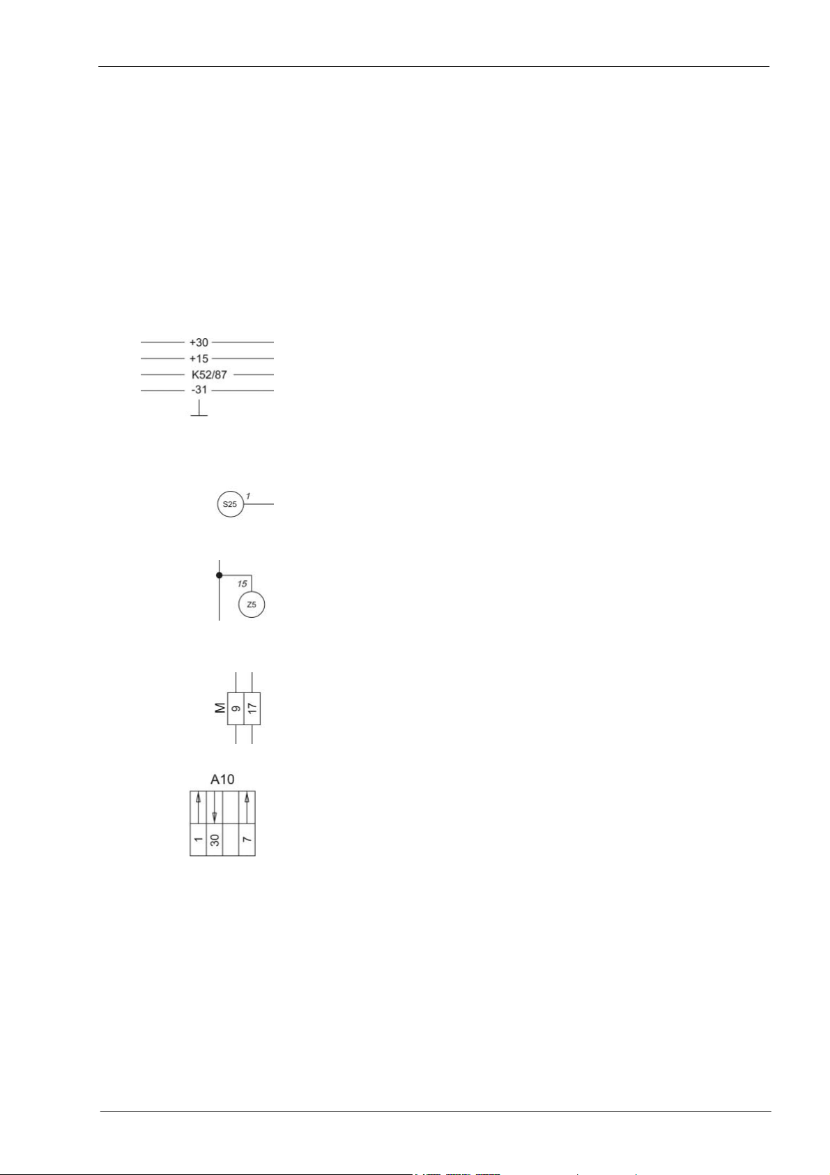
Potentials
- Main power supply (battery)
- Ignition switch power supply (switched)
- Relay-controlled power supply
- Earth
- Housing earth (external)
Connections
- The description provided inside the circle (e.g. „S25”) defines the
connection.
- Numbers next to the circle (e.g. „1”) describe the continuation of the
cabling in accordance with the circuit diagram numbering. This circuit
diagram numbering can be taken among others from the footer.
Example: Many electric circuits depend on the seat contact switch Z5 (see
circuit diagram 17a). The number next to the circle (e.g. 15)
indicates the number of the circuit diagram on which another
function depending on the seat contact is shown.
Designations
- Connectors (e.g. „M”, pin 9 and 17) .
Each chapter lists the respective connectors and their pin assignment
in the individual connection tables.
- Modules (e.g. „A12 - Speed monitor“)
The arrows identify the functional inputs and outputs according to the
assignment table provided in chapter ZE.
Electric System LEXION 500 TIC
7-n-21
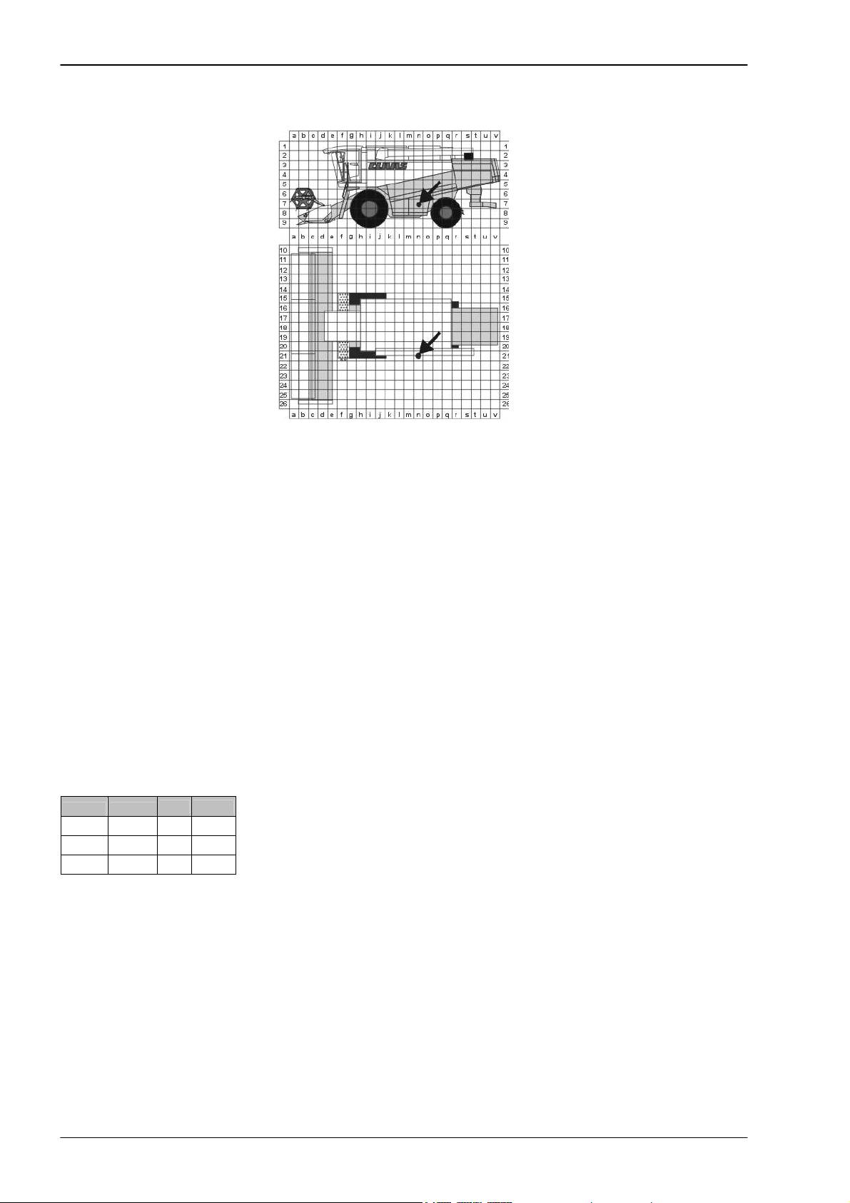
- Position of components according to component grid coordinates
A 1 ... Z 99
- Component designation according to CLAAS standards catalogue
A- Terminal / Module
B- Sensor
E- Lighting
F- Fuse
G- Voltage Source
H- Signalling Device / Lamp
K- Relay
M- Electric Motor
P- Gauge
R- Potentiometer / Resistor
S- Switches – Cab Operation
T- Switches – Terminal Operation
U- Switches – External Operation
V- Electronic Component
W- Antenna
X- Connector
Y- Solenoid coil
Z- Actual Value Function Switch
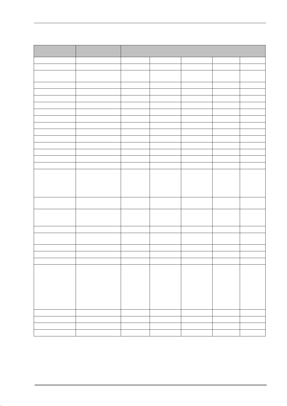
Connections list
from to 1
BB - 5 S 54 0.5 bl-wh
BB -10 Y 25 0.5 bk
MW-17 K49/86 0.75 br
mm2 Colour
- List of connections within the central terminal compartment, stating
cross-section (mm²) and colour of cables connected to the machine.
rd - red
bk - black
br - brown
wh - white
bl - blue
gr -grey
ye - yellow
gn - green
pi - pink
or - orange
vi - violet

TIC LEXION 500 Electric System
Contents:
Central terminal compartment ......................................................................................................................ZE-2
Pin assignment in modules............................................................................................................................ M-2
01a Main power supply, diesel engine electric starting motor................................................................ 01a-2
01s Main power supply, diesel engine electric starting motor - Montana 570-520 .................................01s-2
02a Starting the diesel engine, diesel engine electric starting motor - CAT C12, C10, C9, 3126B ....... 02a-2
02b Starting the diesel engine, diesel engine electric starting motor- DC 502 LA ................................. 02b-2
02s
Starting the diesel engine, diesel engine speed adjustment - CAT C12, C10, C9, 3126B,
Montana 570-520 - with external MONTANA control unit ................................................................02s-
Starting the diesel engine, diesel engine speed adjustment - CAT C12, C10, C9, 3126B,
02t
Montana 570-520 - with integrated MONTANA control unit............................................................. 02t-
Diesel engine cut-off system ........................................................................................................... 03a-2
03a
04a
Road travel activation, master valve................................................................................................ 04a-2
04s
Road travel activation, working hydraulics master valve, Montana 570-520
- with external MONTANA control unit..............................................................................................04s-
04t Road travel activation, working hydraulics master valve, Montana 570-520
- with integrated MONTANA control unit .......................................................................................... 04t-
05a Terminal, keyboard, rotary switch, printer ....................................................................................... 05a-2
05b
Terminal, keyboard, rotary switch, printer - with electro-hydraulic ground drive (EFA) .................. 05b-2
06a
CAN bus, module power supply, for diesel engine CATERPILLAR - C12, C10, C9, 3126B .......... 06a-2
06b CAN bus, module power supply, for diesel engine Daimler - Chrysler DC 502 LA......................... 06b-2
06s
CAN bus, module power supply, Montana 570-520 - with external MONTANA control unit ...........06s-2
06t
CAN bus, module power supply, Montana 570-520 - with integrated MONTANA control unit ........ 06t-2
07a
Threshing mechanism circuit ........................................................................................................... 07a-2
2
2
2
2

Electric System LEXION 500 TIC
08a Concave adjustment / Threshing drum variable-speed drive ..........................................................08a-2
09a Rotor flap adjustment / Rotor variable-speed drive .........................................................................09a-2
10a Fan variable-speed drive .................................................................................................................10a-2
11a Sieve adjustment .............................................................................................................................11a-2
12a Deflector adjustment ........................................................................................................................12a-2
13a Straw and chaff spreader, uni-spreader - LEXION 580................................................................... 13a-2
13b Straw and chaff spreader, radial spreader....................................................................................... 13b-2
14a Swinging the grain tank unloading tube........................................................................................... 14a-2
15a Grain tank unloading / Grain tank unloading aid.............................................................................. 15a-2
16a Rape cutting knife circuit.................................................................................................................. 16a-2
17a Front attachment drive, reverser drive, front attachment quick stop ...............................................17a-2
17s
Front attachment drive, reverser drive, front attachment quick stop, Montana 570-520
- with external MONTANA control unit............................................................................................. 17s-
18a
Front attachment variable-speed drive ............................................................................................18a-2
19a Straw chopper.................................................................................................................................. 19a-2
19b Straw chopper, radial spreader without chaff spreader ................................................................... 19b-2
19c
Straw chopper, radial spreader with chaff spreader ........................................................................ 19c-2
20a
Front attachment raise/lower, cross levelling................................................................................... 20a-2
20s
Raise/lower front attachment, cross levelling - Montana 570-520................................................... 20s-2
21a
Reel adjustment - Standard cutterbar.............................................................................................. 21a-2
21b Reel adjustment - VARIO cutterbar .................................................................................................21b-2
21c
Reel adjustment - Folding cutterbar................................................................................................. 21c-2
21d
Folding the maize picker, snapping plate adjustment, down maize augers .................................... 21d-2
22a Reel variable-speed drive ................................................................................................................ 22a-2
23a
Cutting table adjustment (Vario), folding the cutterbar ....................................................................23a-2
24a AUTOCONTOUR (CAC)..................................................................................................................24a-2
Speed monitor..................................................................................................................................25a-2
25a
2

TIC LEXION 500 Electric System
26a Machine monitor .............................................................................................................................. 26a-2
26s Machine monitor, Montana 570-520 - with external MONTANA control unit ...................................26s-2
Machine monitor, Montana 570-520 - with external MONTANA control unit ................................... 26t-2
26t
27a
Yield meter / Grainmeter ................................................................................................................. 27a-2
28a
AUTOPILOT – Laser system........................................................................................................... 28a-2
AUTOPILOT – Feeler system.......................................................................................................... 28b-2
28b
28c
AUTOPILOT – GPS-controlled steering...........................................................................................28c-2
29a
Performance monitor ....................................................................................................................... 29a-2
Open / close grain tank (electric), grain tank full signal, warning beacon ....................................... 30a-2
30a
30b
Open / close grain tank (hydraulic), grain tank full signal, warning beacon .................................... 30b-2
31a
Front attachment dampening........................................................................................................... 31a-2
32a
All-wheel drive, fuel tank.................................................................................................................. 32a-2
32b
All-wheel drive - Overdrive, fuel tank............................................................................................... 32b-2
33a Cutterbar spring lock........................................................................................................................ 33a-2
34 *not available
35 *not available
36a
Indicator system (Europe) ............................................................................................................... 36a-2
36b
Indicator system (USA).................................................................................................................... 36b-2
37a Windscreen wiper, windscreen washer ........................................................................................... 37a-2
38a
Compressor-type air conditioner ..................................................................................................... 38a-2
38b
Automatic air conditioner ................................................................................................................. 38b-2
39a Cab comfort equipment – Operator's seat....................................................................................... 39a-2
40a
Additional sockets, fuse tester......................................................................................................... 40a-2
41s Axle control system, front attachment control system, Montana 570-520
- with external MONTANA control unit..............................................................................................41s-
41t
Axle control system and front attachment control system, Montana 570-520
- with integrated Montana control unit .............................................................................................. 41t-
42a Ground drive and brake control ....................................................................................................... 42a-2
42s
Ground drive and brake control, Montana 570-520 - with external MONTANA control unit ............42s-2
42t
Ground drive and brake control, Montana 570-520 - with integrated MONTANA control unit......... 42t-2
43 *not available
2
2

Electric System LEXION 500 TIC
44a
Electro-hydraulic gearshift - 3-speed manual gearbox .................................................................... 44a-2
45a
Main lighting circuit, taillight, position light ....................................................................................... 45a-2
46a
Dipped headlights, full beam, dipped headlights changeover switch .............................................. 46a-2
47a
Work lights I .....................................................................................................................................47a-2
Work lights II ....................................................................................................................................48a-2
48a
49a
Sieve, grain tank and returns lighting, reversing horn, brake light................................................... 49a-2
50a
Instrument lighting, broadcast receiver, mirror adjustment.............................................................. 50a-2
Component grid ............................................................................................................................................. R-2
Index ...................................................................................................................................................... index-2

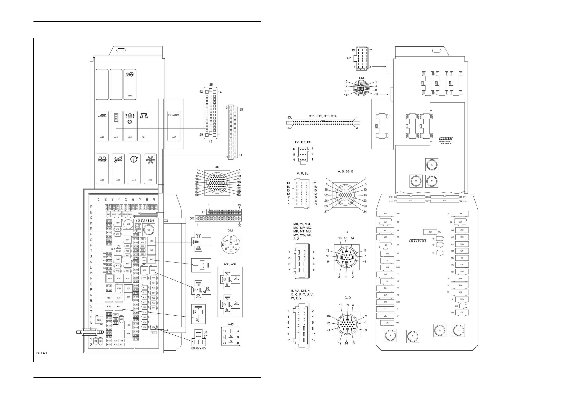
Central terminal compartment
Electric System LEXION 500 TIC
Central terminal compartment
ZE-2 Lex-e-ZE 03/05

TIC LEXION 500 Electric System
Key to diagram:
Centr. term. comp.
position
A08 AUTOCONTOUR module (CAC)
A09 AUTOPILOT module
A10 Fieldwork computer module (BIF/CAB)
A12 Speed monitor module (DZW)
A16 Reel controller module (HAS)
A17 Engine adaptation module (ADM)
A21 YIELD METER module (LEM)
A25 Sieve adjustment module
A28 Uni-spreader module (VGS)
A33 Sidefinder module
A34 Grain tank module
A37 Electro-hydraulic gearshift (EHS) module
A45 Ground drive hydraulic motor brake
DI Warning device diode PCB
D0 Master valve diode PCB
DS Diagnosis (63-pin) VIA
ST1 Connecting cable (ribbon cable)
ST2 Connecting cable (ribbon cable)
ST3 Connecting cable (ribbon cable)
ST4 Connecting cable (ribbon cable)
F1
F2 Sieve adjustment module 12 V control
F3
F4 +12 V electronic unit A 8
F5
F6 Spare (plug MU) K-L 2
F7
F8
F9
F10 Yield meter F 2
F11
F12 Work lights relay C-D 2
F13
F14
F15 Dipped headlights / Full beam Y 4
F16
F17 Electronic unit plus RIO M 6
F18 Cutterbar quick stop L 2
F19
F20 All-wheel drive 12 V switch E 2
F21 Threshing mechanism relay L 6
F22
F23 Hazard warning switch 30 I-J 6
F24
F25
F26 Reel controller S 6
F27 Upper/lower sieve A 2-3
F28
F29 Ground speed control lever limit switch
F30 Brake light switch 12 V / Sieve pan light W-X 6
Modules
restrictor module (HBM)
Electronic components
Fuses
Dipped headlights circuit Z 4
unit
CAN connection of performance monitor A 7-8
12 V air conditioner fan X-Y 2
CAC module A 7
Reel module A 6
Yield meter F 2
Inside work lights V-W 2
Cigarette lighter K 6
Seat socket G-H 7
12 V CAB/DZW A 9
Engine speed switch G 6
Threshing mechanism ON I-J 7
Hazard warning switch 15 I 6
Fan speed relay N 6
Autopilot switch H 7
12 V
Connection
between basic PCB
and module PCB /
Interconnection list
on page ZE-6
G 2
H 6
03/05 Lex-e-ZE ZE-3

Electric System LEXION 500 TIC
Key to diagram:
Centr. term. comp.
position
F31
F32 12 V IMO A 5
F33
F34 Engine ignition X 6
F35 Fold cutterbar N-O 6
F36
F37 12 V grain tank drive Q 6
F38 Work light U 3
F39
F40 Vehicle lighting switch 12 V Z 2
F41
F42 12 V horn / wiper and washer system V 3
F43 Position light, left-hand W 6
F44
F45 Left-hand full beam relay U 6
F46 Left-hand dipped beam relay S 6
F47
F48 Right-hand dipped beam relay R 6
F49 Table adjustment T 6
F50
F51 Ignition diagnosis plug A 6
F52 Instrument lighting X 2
F53
F54 Uni-spreader/Autopilot module A 9
F55 Worklight switch U 2
F56
F57 Spare module J 2
F58 Spare (connector H) O 2
F59
F60 12 V sockets LP/HP T-U 2
F61
F62 Outside railing worklights relay V 2
F63 Power supply for 12 V potentiometers A 5
F64
F65 Spare relay 40A incl. 12 V/30A F 6
F66
F67
F68
F69
F70
F71
F72
F73
F74 Broadcast radio / radio 12 V constant plus Z 3
F75
F76 Maintenance lights J 6
F77 Front attachment electronic unit plus K 2
F78
F79 VCU terminal 30 Y 6
Fuses
Rotary switch 12 V A 3
Air conditioner relay W 2
Grain tank extension I 7
Chopper ON/OFF pushbutton A 4
Warning beacon Y 2
Position light, right-hand V 6
Right-hand full beam relay U-V 6
Grain tank extension P 6
Returns lighting O 6
Spare module H 2
Engine diagnosis G 7
Sidefinder T-U 3
12V speed sensors P 2
12 V deflector adjustment RIO / radial
spreader
Rotor flaps RIO / rotor variator A 4
Wheel position worklights I-J 2
Cooling box socket outlet 12V G-H 6
Ignition switch back-up fuse Y 3
Sieve adjustment module 12V power A 2
MINI ECU M 2
Stubble lighting worklights X 9
Transmission controller 12 V power supply D 2
Diagnosis DC terminal 15 P-Q 6
L 6
ZE-4 Lex-e-ZE 03/05

TIC LEXION 500 Electric System
Key to diagram:
Centr. term. comp.
position
K1
K2 Lower reel R-S 9
K3
K4 Reel backward P-Q 9
K5 Raise cutterbar N 7-8
K6
K7 Cutterbar left-hand cross levelling E 3-4
K8 Cutterbar right-hand cross levelling F 3-4
K9
K10 Table adjustment backward T 7-8
K12
K13 Threshing mechanism On/Off P-Q 7-8
K14 Threshing mechanism On/Off L 3-4
K15
K20 Lighting main relay U-V 4
K23 Generator B-C 5
K24
K25 Left-hand full beam relay U 7-8
K26 Right-hand full beam relay V 7-8
K27
K28 Right-hand dipped beam relay Q-R 7-8
K31 Grain tank extension up O 9
K32
K37 Fan speed - L-M 7-8
K38 Fan speed + L-M 8-9
K41
K42 Upper sieve adjustment + B-C 3
K43 Lower sieve adjustment - B-C 4
K44
K45 Work lights U-V 1
K46
K47 Flash relay USA J-K 8-9
K48 Indicator relay Europe I 8-9
K49
K50 Work lights relay S 2
K51
K52
K53
K54
K55
K56
K57
K58
K59
K60 Wheel position work lights O-P 4
K61
K62 Warning beacon grain tank 70% full Y-Z 1
K63 Fan speed relay J-K 7-8
K66
K67 Spare relay J 5
K68
K69 Spare relay H 5
Relay
Raise reel S 9
Reel forward Q-R 9
Lower cutterbar N 9
Table adjustment forward S 7-8
Ground speed control lever zero position P 7-8
Cutterbar quick stop L-M 3-4
Air conditioner relay W 7-8
Left-hand dipped beam relay R-S 7-8
Grain tank extension down P 9
Upper sieve adjustment - B-C 2
Lower sieve adjustment + B-C 5
Maintenance lights J-K 3-4
Road travel main relay Q-R 4
Relay 15 X 5
Ignition relay 15a S 4
Start relay V-W 5
Stubble lighting W 9
Work lights relay Q-R 2
Electronic unit plus L-M 5
Transducer G-H 8-9
Alternator relay K-L 5
Work lights relay D 3-4
Warning beacon Y-Z 1
Spare relay 40 A G 5
Spare relay I 5
03/05 Lex-e-ZE ZE-5

Electric System LEXION 500 TIC
Connecting cable Boards – Central terminal compartment
(Assignment table: Module → Connector): 1/5
Module board
Module / Pin
A08 01
A08 02
A08 03
A08 05
A08 06
A08 07
A08 08
A08 12
A08 13
A08 14
A08 15
A08 16
A08 18
A08 19
A08 20
A08 22
A08 25
A10 01
A10 02
A10 03
A10 04
A10 05
A10 06
A10 09
A10 10
A10 13
A10 14
A10 15
A10 16
A10 17
A10 18
A10 19
A10 20
Connecting cable
ST 1-4 Pin
ST3 36
ST2 63,64
ST1 23
ST2 43
ST2 51
ST4 13
ST1 35
ST2 40
ST2 36
ST3 35
ST3
17
18
ST1 21
ST2 49
ST2 41
23, 24
25, 26
ST2
27, 28
29, 30
31, 32
ST1 39
ST3 32
55, 56
57, 58
ST3
59, 60
61, 62
63, 64
ST2 50
ST4 13
ST2 58
ST2 33
ST2 46
ST3 54
ST2 19
ST1 21
ST3
33
34
ST3 53
ST3 50
ST4 1
ST2 57
ST2 52
ST4 12
Motherboard
Connector / Pin
K8 87 SL 10 MQ 3
Z 8 Q 12
MW 3 MV 3 MU 3
M 3
M 5
H 3 DS 53 W 2
E 25 DS 48
V 5 K5 87 DO 8
V 6 K6 87 DS 6
K7 87 MQ 4 SL 11
F07 a DS 5
MW 4 MV 4 MU 4
M 6
M 1
N 12 F35 a U 7
E 27
DO 1
F16 a
K38 86
H 3 DS 53 W 2
P 6 MO 1
MA 8
Z 3
M 9 DI 1
P 4 R 1 A34 2R
E 30 MO 4 MP 4
F04 a
V 2 DO 13
K37 86
P 14
SL 7 DS 2
O 10 DS 1 SL 8
W 1 F22 a K63 86 MN 2 DS 52
ZE-6 Lex-e-ZE 03/05

TIC LEXION 500 Electric System
Connecting cable Boards – Central terminal compartment
(Assignment table: Module → Connector): 2/5
Module board
Module / Pin
A10 24
A10 27
A10 29
A10 32
A10 33
A10 34
A10 40
A10 41
A10 42
A12 01
A12 02
A12 03
A12 04
A12 12
A12 13
A12 14
A12 15
A12 16
A12 20
A12 25
A16 01
A16 02
A16 03
A16 04
A16 05
A16 07
A16 08
A16 09
A16 10
A16 13
A16 14
A16 15
A16 16
A16 17
A16 18
A16 20
Connecting cable
ST 1-4 Pin
ST4 10
ST2 13
ST2 34
ST1 20
ST4 2
ST1 32
ST1 23
ST2 47
ST2 11
ST3 49
ST3 38
ST1 23
ST1 19
ST1 42
ST3 4
ST2 10
ST3
33
34
ST1 21
55, 56
57, 58
ST3
59, 60
61, 62
63, 64
ST2 14
ST2 48
ST2
63
64
ST1 23
ST1 40
ST1 36
ST2 37
ST1 22
ST3 3
ST2 54
ST2 22
ST2 56
ST3 1,2
ST1 21
ST1 34
ST3 20
19, 20
21, 22
ST3
23, 24
25, 26
27, 28
Motherboard
Connector / Pin
O 9
G 11 XM G
V 1
Z 4
P 15
C 18 G 16 K58 86 MM 8
E 31 MO 7 MP 3
G 9 XM F
G 12 XM C
Q 1 DO 17
Y 1 Y 12 MO 8 E 1 E 12
E 31 MO 7 MP 3
W 10 MN 3 DS 17
V 8 DO 15
V 7 DO 16
Q 2
F04 a
E 30 MO 4 MP 4
F16 a
P 7
E 6 DS 20 DO 3 K1 87
Z 8 Q 12
MW 3 MV 3 MU 3
P 8 MQ 5 DO 2 DS 7 SL 12
E 22
N 11
E 24
Z 5
E 28
Q 7 DS 24
E 7 K2 87 DS 21
F08 a
MW 4 MV 4 MU 4
E 29 MA 12
K3 86 K3 30 K4 86 K4 30 K2 30
Q 4 F26 a K1 86 K1 30 K2 86
03/05 Lex-e-ZE ZE-7

Electric System LEXION 500 TIC
Connecting cable Boards – Central terminal compartment
(Assignment table: Module → Connector): 3/5
Module board
Module / Pin
A16 21
A16 22
A16 25
A25 01
A25 02
A25 03
A25 08
A25 12
A25 13
A25 14
A25 15
A25 16
A25 20
A28 02
A28 03
A28 07
A28 11
A28 12
A28 13
A28 15
A28 16
A28 20
A28 25
A28 13
A28 15
A28 16
A28 20
A28 25
Connecting cable
ST 1-4 Pin
ST1 38
ST2 45
ST2 44
ST4 4
ST3 39
ST1 23
ST2 39
ST4 3
ST4 6
ST4 5
ST4 17
ST1 21
ST1
61, 62
63, 64
ST3 40
ST1 23
1, 2, 3, 4
ST1
5, 6, 7, 8
9, 10
ST1 26
ST1
ST1
ST3
11, 12
13, 14
53, 54
55, 56
51
52
ST1 21
1, 2, 3, 4,
ST1
5, 6, 7, 8,
9, 10
ST1
ST1
15, 16
17, 18
53, 54
55, 56
ST3 51, 52
ST1 21
1, 2, 3, 4,
ST1
5, 6, 7, 8
9, 10
ST1
15, 16,
17, 18
Motherboard
Connector / Pin
E 23
Q 3
Q 8 DS 25
K42 86
MH 2 MH 7 MU 2 MP 2 H 1
A45 3 SL 4 MR 3 DS 62
DS 46
K41 86
K44 86
K43 86
MV 1 F02 a MW 1
A45 9 SL 5 MR 4 DS 63
F71 a
R 3 MV 2 K55 85 O 4 MW 2
A45 3 SL 4 MR 3 DS 62
DS 49 MN 7
DS 47
DS 26 MN 5
DS 27 MN 6
MR 1 F54 a
A45 9 SL 5 MR 4 DS 63
DS 49 MN 7
MN 8
DS 27 MN 6
MR 1 F54 a
A45 9 SL 5 MR 4 DS 63
DS 49 MN 7
MN 8
ZE-8 Lex-e-ZE 03/05
TIC LEXION 500 Electric System
Connecting cable Boards – Central terminal compartment
(Assignment table: Module → Connector): 4/5
Module board
Module / Pin
A 01
A 04
A 05
A 06
A 08
A 09
A 10
A 11
A 12
A 14
A 15
A 16
A 17
A 18
A 19
A 20
A 21
A 22
A 23
A 28
A 34
B 01
B 02
B 03
B 07
B 08
B 09
B 10
Connecting cable
ST 1-4 Pin
ST4 19
ST4 15
ST2
59
60
ST1 24
ST2 61
ST1 29
ST1 33
ST2 9
ST2 53
ST1 31
ST2 55
ST2 62
ST2 21
ST4 16
ST1 23
ST1 21
43, 44
45, 46
ST1
47, 48
49, 50
51, 52
ST2
1, 2, 3, 4,
5, 6, 7, 8
5, 6, 7, 8,
ST3
9, 10, 11,
12, 13, 14
ST4 7, 8, 9
ST2
63
64
ST1 41
ST4 18
50, 51
52, 53
54, 55
ST4
56, 57
58, 59
60, 61
62, 63
64
ST4 5
ST4 6
ST4 3
ST4 4
Motherboard
Connector / Pin
U 10 SL 20
MN 4 DS 33
A34 4R H 6 DS 16 W 4
G 14 K24 85
A34 8L W 3 H 5 M 21 DS 15
MH 6
MH 8
T 8 Y 2 SL 6
G 6 DI 13
MH 5 K62 85
W 9 DI 4
W 5
K23 87a G 13
K57 49a C 20
E 31 MO 7 MP 3
E 30 MO 4 MP 4
F32 a
MA 10 DS 61 U 4 MT 8 K46 85
F51 a DS 58 DS 59
F31 a DS 56
Z 8 Q 12
Z 6 DS 51 F64 a
F17 a MO 5 SL 14 K5 86 K5 30
F67 a
K43 86
K44 86
K41 86
K42 86
03/05 Lex-e-ZE ZE-9

Electric System LEXION 500 TIC
Connecting cable Boards – Central terminal compartment
(Assignment table: Module → Connector): 5/5
Module board
Module / Pin
B 11
B 13
B 14
B 15
B 16
B 17
B 20
B 23
B 24
B 25
B 26
B 27
B 28
B 29
B 30
B 31
B 33
B 34
BB 10
BB 12
BB 13
BB 19
BB 24
BB 29
Connecting cable
ST 1-4 Pin
ST1
61, 62
63, 64
ST1 23
ST1 21
32, 33
34, 35
ST4
36, 37
38, 39
40, 41
ST4
ST4
42, 43
44, 45
46, 47
48, 49
ST2 59, 60
ST1 34
ST3 29
ST2 2
ST4
ST4
ST4
ST1
20, 21
22, 23
24, 25
26, 27
28, 29
30, 31
57, 58
59, 60
ST1 27, 28
ST1 35
ST2 64
ST2 39
ST1 35
ST2 64
ST1 27, 28
ST1 26
ST1 41
ST2 3
ST2 24
ST2 25
ST2
15, 16
17, 18
ST3 15, 16
Motherboard
Connector / Pin
F71 a
MW 3 MV 3 MU 3
MW 4 MV 4 MU 4
F39 a
Q 6 DS 18 DO 22
Q 5 DS 19 DO 20
A34 4R H 6 DS 16 W 4
E 29 MA 12
F03 a MU 1
P 12 MI 2 T 7 T 6 C 16
K41 30
K42 30
K43 30
K44 30
DS 57 MU 8 MR 5 F63 a
E 25 DS 48
CB 2 Bridge a E 37
DS 46
E 25 DS 48
CB 2 Bridge a E 37
DS 57 MU 8 MR 5 F63 a
DS 47
Z 6 DS 51 F64 a
MQ 8 V 12 V 11 MT 4 MT 3
K6 30 K6 86 K7 86 K7 30
K8 86 K8 30
ZE-10 Lex-e-ZE 03/05
Central terminal compartment
Montana 570-520
- with external MONTANA control unit
- up to serial no. 582 00051
581 00026
580 00028
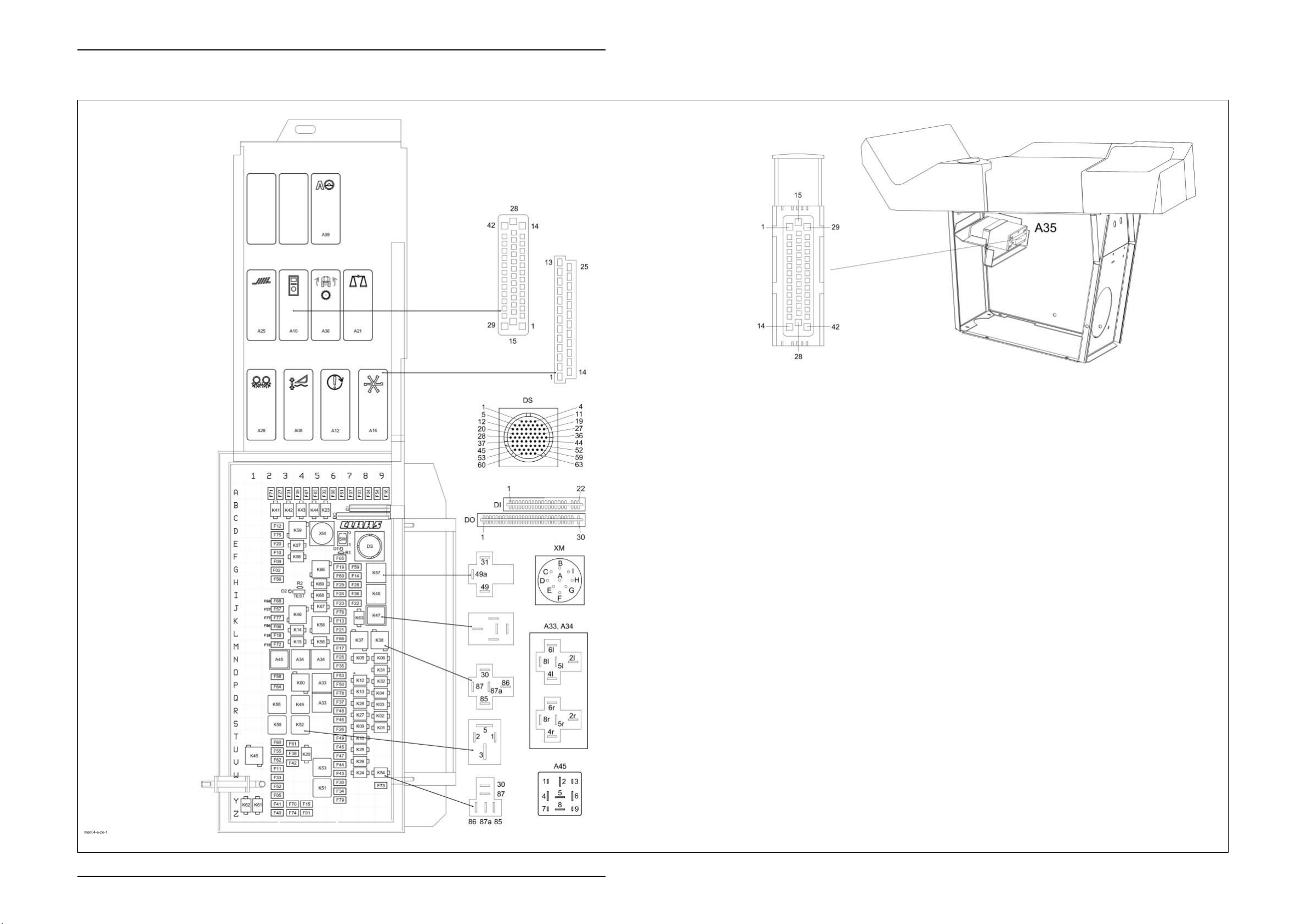
Electric System LEXION Montana 570-520 TIC
Central terminal compartment Montana 570-520 - with external MONTANA control unit
(up to serial no. 582 00051, 581 00026; 580 00028)
ZE-12 Lex-e-ZE 03/05

TIC LEXION Montana 570-520 Electric System
Key to diagram:
Centr. term.
comp. position
A08 AUTOCONTOUR module (CAC)
A09 AUTOPILOT module
A10 Fieldwork computer module (BIF/CAB)
A12 Speed monitor module (DZW)
A16 Reel controller module (HAS)
A17 Engine adaptation module (ADM)
A21 YIELD METER module (LEM)
A25 Sieve adjustment module
A28 Uni-spreader module (VGS)
A33 Sidefinder module
A34 Grain tank module
A35 MONTANA control unit module
A36 MONTANA gearshift control module
A45 Ground drive hydraulic motor brake restrictor
DI Warning device diode PCB
D0 Master valve diode PCB
DS Diagnosis (63-pin) VIA
ST1 Connecting cable (ribbon cable)
ST2 Connecting cable (ribbon cable)
ST3 Connecting cable (ribbon cable)
ST4 Connecting cable (ribbon cable)
F1
F2 Sieve adjustment module 12 V control unit G 2
F3
F4 +12 V electronic unit A 8
F5
F6 Spare (MU connector) K-L 2
F7
F8
F9
F10
F11
F12
F13
F14
F15
F16 12 V CAB/DZW A 9
F17
F18 Cutterbar quick stop L 2
F19 Engine speed switch G 6
F20
F21 Threshing mechanism relay L 6
F22 Threshing mechanism ON I-J 7
F23
F24 Hazard warning switch 15 I 6
F25
F26
F27 Upper/lower sieve A 2-3
F28
F29
F30 Brake light switch 12 V / Sieve pan light W-X 6
Modules
module (HBM)
Electronic components
Fuses
Dipped headlights circuit Z 4
CAN connection of performance monitor A 7-8
12 V air conditioner fan X-Y 2
CAC module A 7
Reel module A 6
Yield meter F 2
Yield meter F 2
Inside work lights V-W 2
Work lights relay C-D 2
Cigarette lighter K 6
Seat socket G-H 7
Dipped headlights / Full beam Y 4
Electronic unit plus M 6
All-wheel drive 12 V switch E 2
Hazard warning switch 30 I-J 6
Fan speed relay N 6
Reel controller S 6
Autopilot switch H 7
Ground speed control lever limit switch 12 V H 6
Connection
between basic
PCB and module
PCB /
Interconnection
list on page ZE-6
03/05 Lex-e-ZE ZE-13

Electric System LEXION Montana 570-520 TIC
Key to diagram:
Centr. term.
comp. position
F31
F32 12 V IMO A 5
F33
F34 Engine ignition X 6
F35 Cutterbar fold N-O 6
F36
F37 12 V grain tank drive Q 6
F38 Work light U 3
F39
F40 Vehicle lighting switch 12 V Z 2
F41
F42 12 V horn / wiper and washer system V 3
F43 Position light, left-hand W 6
F44
F45 Left-hand full beam relay U 6
F46 Left-hand dipped beam relay S 6
F47
F48 Right-hand dipped beam relay R 6
F49 Table adjustment T 6
F50
F51 Ignition diagnosis plug A 6
F52 Instrument lighting X 2
F53
F54 Uni-spreader/Autopilot module A 9
F55 Worklight switch U 2
F56
F57 Spare module J 2
F58 Spare (connector H) O 2
F59
F60 12V sockets LP/HP T-U 2
F61
F62 Outside railing worklights relay V 2
F63 Power supply for 12 V potentiometers A 5
F64
F65 Spare relay 40 A incl. 12 V/30 A F 6
F66
F67
F68
F69
F70
F71
F72
F73
F74
F75 Transmission controller 12 V power supply D 2
F76
F77 Front attachment electronic unit plus K 2
F78 Diagnosis DC terminal 15 P-Q 6
F79
Fuses
Rotary switch 12 V A 3
Air conditioner relay W 2
Grain tank extension I 7
Chopper On/Off pushbutton A 4
Warning beacon Y 2
Position light, right-hand V 6
Right-hand full beam relay U-V 6
Grain tank extension P 6
Returns lighting O 6
Spare module H 2
Engine diagnosis G 7
Sidefinder T-U 3
12 V speed sensors P 2
12 V Deflector adjustment / Radial spreader L 6
Rotor flaps / rotor variator A 4
Wheel position worklights I-J 2
Cooling box socket outlet 12 V G-H 6
Ignition switch back-up fuse Y 3
Sieve adjustment module 12 V power A 2
MINI ECU M 2
Stubble lighting worklights X 9
Radio / Mobile radio 12 V constant plus Z 3
Maintenance lights J 6
VCU terminal 30 Y 6
ZE-14 Lex-e-ZE 03/05

TIC LEXION Montana 570-520 Electric System
Key to diagram:
Centr. term.
comp. position
K1
K2 Lower reel R-S 9
K3
K4 Reel backward P-Q 9
K5 Raise cutterbar N 7-8
K6
K7 Cutterbar left-hand lateral levelling E 3-4
K8 Cutterbar right-hand lateral levelling F 3-4
K9
K10 Table adjustment backward T 7-8
K12
K13 Threshing mechanism On/Off P-Q 7-8
K14 Threshing mechanism On/Off L 3-4
K15
K20 Lighting main relay U-V 4
K23 Alternator B-C 5
K24
K25 Left-hand full beam relay U 7-8
K26 Right-hand full beam relay V 7-8
K27
K28 Right-hand dipped beam relay Q-R 7-8
K31 Grain tank extension up O 9
K32
K37 Fan speed - L-M 7-8
K38 Fan speed + L-M 8-9
K41
K42 Upper sieve adjustment + B-C 3
K43 Lower sieve adjustment - B-C 4
K44
K45 Work lights U-V 1
K46
K47 Flash relay USA J-K 8-9
K48 Indicator relay Europe I 8-9
K49
K50 Work lights relay S 2
K51
K52
K53
K54
K55
K56
K57
K58
K59
K60 Wheel position work lights O-P 4
K61
K62 Warning beacon grain tank 70% full Y-Z 1
K63 Fan speed relay J-K 7-8
K66
K67 Spare relay J 5
K68
K69 Spare relay H 5
Relays
Raise reel S 9
Reel forward Q-R 9
Lower cutterbar N 9
Table adjustment forward S 7-8
Ground speed control lever zero position P 7-8
Cutterbar quick stop L-M 3-4
Air conditioner relay W 7-8
Left-hand dipped beam relay R-S 7-8
Grain tank extension down P 9
Upper sieve adjustment - B-C 2
Lower sieve adjustment + B-C 5
Maintenance lights J-K 3-4
Road travel main relay Q-R 4
Relay 15 X 5
Ignition relay 15a S 4
Start relay V-W 5
Stubble lighting W 9
Work lights relay Q-R 2
Electronic unit plus L-M 5
Transducer G-H 8-9
Alternator relay K-L 5
Work lights relay D 3-4
Warning beacon Y-Z 1
Spare relay 40 A G 5
Spare relay I 5
03/05 Lex-e-ZE ZE-15

Electric System LEXION Montana 570-520 TIC
ZE-16 Lex-e-ZE 03/05
Central terminal compartment
Montana 570-520
- with integrated MONTANA control unit
- from serial no. 581 00027 to 581 00037
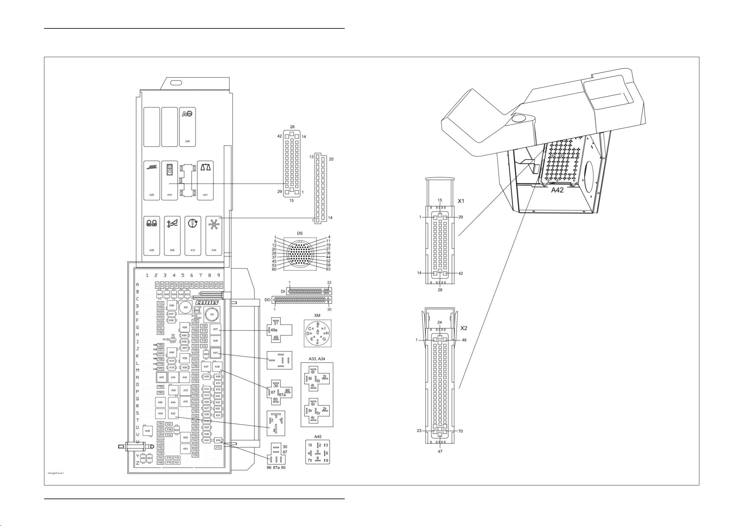
Electric System LEXION Montana 570-520 TIC
Central terminal compartment Montana 570-520 - with integrated MONTANA control unit
(from serial no. 581 00027 to 581 00037)
ZE-18 Lex-e-ZE 03/05

TIC LEXION Montana 570-520 Electric System
Key to diagram:
Centr. term.
comp. position
A08 AUTOCONTOUR module (CAC)
A09 AUTOPILOT module
A10 Fieldwork computer module (BIF/CAB)
A12 Speed monitor module (DZW)
A16 Reel controller module (HAS)
A17 Engine adaptation module (ADM)
A21 YIELD METER module (LEM)
A25 Sieve adjustment module
A28 Uni-spreader module (VGS)
A33 Sidefinder module
A34 Grain tank module
A42 MONTANA GEN II module
A45 Ground drive hydraulic motor brake restrictor
DI Warning device diode PCB
D0 Master valve diode PCB
DS Diagnosis (63-pin) VIA
ST1 Connecting cable (ribbon cable)
ST2 Connecting cable (ribbon cable)
ST3 Connecting cable (ribbon cable)
ST4 Connecting cable (ribbon cable)
F1
F2 Sieve adjustment module 12 V control unit G 2
F3 CAN connection of performance monitor A 7-8
F4
F5 12 V air conditioner fan X-Y 2
F6
F7 CAC module A 7
F8
F9
F10
F11
F12
F13
F14
F15
F16
F17 Electronic unit plus M 6
F18
F19 Engine speed switch G 6
F20 All-wheel drive 12 V switch E 2
F21
F22 Threshing mechanism ON I-J 7
F23 Hazard warning switch 30 I-J 6
F24
F25 Fan speed relay N 6
F26
F27
F28 Autopilot switch H 7
F29
F30 Brake light switch 12 V / Sieve pan light W-X 6
Modules
module (HBM)
Electronic components
Fuses
Dipped headlights circuit Z 4
+12 V electronic unit A 8
Spare (MU connector) K-L 2
Reel module A 6
Yield meter F 2
Yield meter F 2
Inside work lights V-W 2
Work lights relay C-D 2
Cigarette lighter K 6
Seat socket G-H 7
Dipped headlights / Full beam Y 4
12 V CAB/DZW A 9
Cutterbar quick stop L 2
Threshing mechanism relay L 6
Hazard warning switch 15 I 6
Reel controller S 6
Upper/lower sieve A 2-3
Ground speed control lever limit switch 12 V H 6
Connection
between basic
PCB and module
PCB /
Interconnection
list on page ZE-6
03/05 Lex-e-ZE ZE-19

Electric System LEXION Montana 570-520 TIC
Key to diagram:
Centr. term.
comp. position
F31
F32 12 V IMO A 5
F33
F34 Engine ignition X 6
F35 Cutterbar fold N-O 6
F36
F37 12 V grain tank drive Q 6
F38 Work light U 3
F39
F40 Vehicle lighting switch 12 V Z 2
F41
F42 12 V horn / wiper and washer system V 3
F43 Position light, left-hand W 6
F44
F45 Left-hand full beam relay U 6
F46 Left-hand dipped beam relay S 6
F47
F48 Right-hand dipped beam relay R 6
F49 Table adjustment T 6
F50
F51 Ignition diagnosis plug A 6
F52 Instrument lighting X 2
F53
F54 Uni-spreader/Autopilot module A 9
F55 Worklight switch U 2
F56
F57 Spare module J 2
F58 Spare (connector H) O 2
F59
F60 12V sockets LP/HP T-U 2
F61
F62 Outside railing worklights relay V 2
F63 Power supply for 12 V potentiometers A 5
F64
F65 Spare relay 40 A incl. 12 V/30 A F 6
F66
F67
F68
F69
F70
F71
F72
F73
F74
F75 Transmission controller 12 V power supply D 2
F76
F77 Front attachment electronic unit plus K 2
F78 Diagnosis DC terminal 15 P-Q 6
F79
Fuses
Rotary switch 12 V A 3
Air conditioner relay W 2
Grain tank extension I 7
Chopper On/Off pushbutton A 4
Warning beacon Y 2
Position light, right-hand V 6
Right-hand full beam relay U-V 6
Grain tank extension P 6
Returns lighting O 6
Spare module H 2
Engine diagnosis G 7
Sidefinder T-U 3
12 V speed sensors P 2
12 V Deflector adjustment / Radial spreader L 6
Rotor flaps / rotor variator A 4
Wheel position worklights I-J 2
Cooling box socket outlet 12 V G-H 6
Ignition switch back-up fuse Y 3
Sieve adjustment module 12 V power A 2
MINI ECU M 2
Stubble lighting worklights X 9
Radio / Mobile radio 12 V constant plus Z 3
Maintenance lights J 6
VCU terminal 30 Y 6
ZE-20 Lex-e-ZE 03/05

TIC LEXION Montana 570-520 Electric System
Key to diagram:
Centr. term.
comp. position
K1
K2 Lower reel R-S 9
K3
K4 Reel backward P-Q 9
K5 Raise cutterbar N 7-8
K6
K7 Cutterbar left-hand lateral levelling E 3-4
K8 Cutterbar right-hand lateral levelling F 3-4
K9
K10 Table adjustment backward T 7-8
K12
K13 Threshing mechanism On/Off P-Q 7-8
K14 Threshing mechanism On/Off L 3-4
K15
K20 Lighting main relay U-V 4
K23 Alternator B-C 5
K24
K25 Left-hand full beam relay U 7-8
K26 Right-hand full beam relay V 7-8
K27
K28 Right-hand dipped beam relay Q-R 7-8
K31 Grain tank extension up O 9
K32
K37 Fan speed - L-M 7-8
K38 Fan speed + L-M 8-9
K41
K42 Upper sieve adjustment + B-C 3
K43 Lower sieve adjustment - B-C 4
K44
K45 Work lights U-V 1
K46
K47 Flash relay USA J-K 8-9
K48 Indicator relay Europe I 8-9
K49
K50 Work lights relay S 2
K51
K52
K53
K54
K55
K56
K57
K58
K59
K60 Wheel position work lights O-P 4
K61
K62 Warning beacon grain tank 70% full Y-Z 1
K63 Fan speed relay J-K 7-8
K66
K67 Spare relay J 5
K68
K69 Spare relay H 5
Relays
Raise reel S 9
Reel forward Q-R 9
Lower cutterbar N 9
Table adjustment forward S 7-8
Ground speed control lever zero position P 7-8
Cutterbar quick stop L-M 3-4
Air conditioner relay W 7-8
Left-hand dipped beam relay R-S 7-8
Grain tank extension down P 9
Upper sieve adjustment - B-C 2
Lower sieve adjustment + B-C 5
Maintenance lights J-K 3-4
Road travel main relay Q-R 4
Relay 15 X 5
Ignition relay 15a S 4
Start relay V-W 5
Stubble lighting W 9
Work lights relay Q-R 2
Electronic unit plus L-M 5
Transducer G-H 8-9
Alternator relay K-L 5
Work lights relay D 3-4
Warning beacon Y-Z 1
Spare relay 40 A G 5
Spare relay I 5
03/05 Lex-e-ZE ZE-21

Electric System LEXION Montana 570-520 TIC
ZE-22 Lex-e-ZE 03/05
 Loading...