

Claas LEXION 600, LEXION 570, LEXION 550, LEXION 560, LEXION 540 Repair Manual Supplement
...
LEXION 560-510
LEXION 600-570
Repair manual
supplement

82703
!
s
n
o
i
t
c
u
r
t
s
n
i
y
t
e
f
a
s
e
h
t
P
l
e
a
s
e
w
o
l
l
o
f
d
n
a
d
a
e
r

Contents
1 Introduction
1.1 General information . . . . . . . . . . . . . . . . . . . . . . . . . . . . . . . . . . . . . . . . . . . . . . . . . . . . . . . . . . . . . . . 6
1.1.1 Validity of manual . . . . . . . . . . . . . . . . . . . . . . . . . . . . . . . . . . . . . . . . . . . . . . . . . . . . . . . . . . . . 6
2 Feed rake conveyor
2.1 Feed rake conveyor . . . . . . . . . . . . . . . . . . . . . . . . . . . . . . . . . . . . . . . . . . . . . . . . . . . . . . . . . . . . . . . 7
2.1.1 Replacing the HP feed rake conveyor anti-slip strips . . . . . . . . . . . . . . . . . . . . . . . . . . . . . . . . . 7
3 Straw discharge
3.1 Chaff spreader . . . . . . . . . . . . . . . . . . . . . . . . . . . . . . . . . . . . . . . . . . . . . . . . . . . . . . . . . . . . . . . . . . . 8
3.1.1 Overview of chaff spreader / chaff spreader fan LEXION 600 - 560 (type 589 - 584) . . . . . . . . 8
3.1.2 Overview of radial spreader LEXION 600 - 560 (type 589 - 584) . . . . . . . . . . . . . . . . . . . . . . . 10
3.2 Straw spreader . . . . . . . . . . . . . . . . . . . . . . . . . . . . . . . . . . . . . . . . . . . . . . . . . . . . . . . . . . . . . . . . . . 12
3.2.1 Overview of straw spreader . . . . . . . . . . . . . . . . . . . . . . . . . . . . . . . . . . . . . . . . . . . . . . . . . . . 12
4 Drives
4.1 Drive belts / drive chains . . . . . . . . . . . . . . . . . . . . . . . . . . . . . . . . . . . . . . . . . . . . . . . . . . . . . . . . . . 14
4.1.1 Drive diagram, left side (LEXION 600 with JET STREAM cleaning system) . . . . . . . . . . . . . . 14
4.1.2 Drive diagram, right side (LEXION 600 with JET STREAM cleaning system) . . . . . . . . . . . . . 16
4.1.3 Drive diagram, left side (LEXION 580 with standard cleaning system) . . . . . . . . . . . . . . . . . . 17
4.1.4 Drive diagram, right side (LEXION 580 with standard cleaning system) . . . . . . . . . . . . . . . . . 19
4.1.5 Drive diagram, left side (LEXION 570 with standard cleaning system) . . . . . . . . . . . . . . . . . . 21
4.1.6 Drive diagram, right side (LEXION 570 with standard cleaning system) . . . . . . . . . . . . . . . . . 23
4.1.7 Drive diagram, left side (LEXION 570 with JET STREAM cleaning system) . . . . . . . . . . . . . . 24
4.1.8 Drive diagram, right side (LEXION 570 with JET STREAM cleaning system) . . . . . . . . . . . . . 26
4.1.9 Drive diagram, left side (LEXION 560 - 510 with standard cleaning system) . . . . . . . . . . . . . . 28
4.1.10 Drive diagram, right side (LEXION 560 - 510 with standard cleaning system) . . . . . . . . . . . . . 30
4.1.11 Removing belt (R26) . . . . . . . . . . . . . . . . . . . . . . . . . . . . . . . . . . . . . . . . . . . . . . . . . . . . . . . . 31
4.1.12 Installing belt (R26) . . . . . . . . . . . . . . . . . . . . . . . . . . . . . . . . . . . . . . . . . . . . . . . . . . . . . . . . . . 32
4.1.13 Adjusting belt (R26) . . . . . . . . . . . . . . . . . . . . . . . . . . . . . . . . . . . . . . . . . . . . . . . . . . . . . . . . . 34
4.2 Fan drive of JET STREAM cleaning system LEXION 570 . . . . . . . . . . . . . . . . . . . . . . . . . . . . . . . . 35
4.2.1 Overview of fan variable-speed drive (electric) from serial no. ... . . . . . . . . . . . . . . . . . . . . . . . 35
4.2.2 Overview of fan variable-speed drive (spring-loaded) from serial no. ... . . . . . . . . . . . . . . . . . 37
4.2.3 Overview of fan variable-speed drive from serial no. ... . . . . . . . . . . . . . . . . . . . . . . . . . . . . . . 39
4.3 Special tool for fan drive of JET STREAM cleaning system LEXION 570 . . . . . . . . . . . . . . . . . . . 41
4.3.1 Disassembling the fan variable-speed drive (spring-loaded) from serial no. ... . . . . . . . . . . . . 41
4.3.2 Disassembling the fan variable-speed drive (spring-loaded) from serial no. ... . . . . . . . . . . . . 42
4.4 Front attachment drive . . . . . . . . . . . . . . . . . . . . . . . . . . . . . . . . . . . . . . . . . . . . . . . . . . . . . . . . . . . . 43
4.4.1 Overview of belt (R2) . . . . . . . . . . . . . . . . . . . . . . . . . . . . . . . . . . . . . . . . . . . . . . . . . . . . . . . . 43
4.4.2 Removing the drive pulley of belt (R2) from serial no. ... . . . . . . . . . . . . . . . . . . . . . . . . . . . . . 44
4.4.3 Overview of drive pulley of belt (R2) from serial no. ... . . . . . . . . . . . . . . . . . . . . . . . . . . . . . . . 45
4.4.4 Installing drive pulley of belt (R2) from serial no. ... . . . . . . . . . . . . . . . . . . . . . . . . . . . . . . . . . 46
4.4.5 Overview of belt (R3) (with front attachment variable-speed drive) . . . . . . . . . . . . . . . . . . . . . 47
4.4.6 Removing the front attachment variable-speed drive (hydraulic) from serial no. ... . . . . . . . . . 48
4.4.7 Overview of front attachment variable-speed drive (hydraulic) from serial no. ... . . . . . . . . . . . 49
4.4.8 Installing the front attachment variable-speed drive (hydraulic) from serial no. ... . . . . . . . . . . 50
4.4.9 Overview of belt (R3) (with front attachment step drive) . . . . . . . . . . . . . . . . . . . . . . . . . . . . . 52
4.4.10 Overview of belt (R26) . . . . . . . . . . . . . . . . . . . . . . . . . . . . . . . . . . . . . . . . . . . . . . . . . . . . . . . 53
82703
3

4.4.11 Removing drive pulley of belt (R26) . . . . . . . . . . . . . . . . . . . . . . . . . . . . . . . . . . . . . . . . . . . . . 54
4.4.12 Overview of drive pulley of belt (R26) . . . . . . . . . . . . . . . . . . . . . . . . . . . . . . . . . . . . . . . . . . . 55
4.4.13 Installing the drive pulley of belt (R26) . . . . . . . . . . . . . . . . . . . . . . . . . . . . . . . . . . . . . . . . . . . 56
4.4.14 Removing the driven pulley of belt (R26) . . . . . . . . . . . . . . . . . . . . . . . . . . . . . . . . . . . . . . . . . 56
4.4.15 Overview of driven pulley of belt (R26) . . . . . . . . . . . . . . . . . . . . . . . . . . . . . . . . . . . . . . . . . . 58
4.4.16 Installing the driven pulley of belt (R26) . . . . . . . . . . . . . . . . . . . . . . . . . . . . . . . . . . . . . . . . . . 59
4.4.17 Overview of jockey pulley of belt (R26) . . . . . . . . . . . . . . . . . . . . . . . . . . . . . . . . . . . . . . . . . . 60
4.5 Special tools for front attachment drive . . . . . . . . . . . . . . . . . . . . . . . . . . . . . . . . . . . . . . . . . . . . . 61
4.5.1 Installing drive pulley of belt (R2) from serial no. ... . . . . . . . . . . . . . . . . . . . . . . . . . . . . . . . . . 61
4.5.2 Removing the front attachment variable-speed drive (hydraulic) from serial no. ... . . . . . . . . . 62
4.5.3 Installing the front attachment variable-speed drive (hydraulic) from serial no. ... . . . . . . . . . . 63
4.5.4 Installing the drive pulley of belt (R26) . . . . . . . . . . . . . . . . . . . . . . . . . . . . . . . . . . . . . . . . . . . 64
4.5.5 Removing the driven pulley of belt (R26) . . . . . . . . . . . . . . . . . . . . . . . . . . . . . . . . . . . . . . . . . 65
4.5.6 Installing the driven pulley of belt (R26) . . . . . . . . . . . . . . . . . . . . . . . . . . . . . . . . . . . . . . . . . . 66
4.6 Impeller drive . . . . . . . . . . . . . . . . . . . . . . . . . . . . . . . . . . . . . . . . . . . . . . . . . . . . . . . . . . . . . . . . . . . 67
4.6.1 Removing the driven pulley of belt (R5) from serial no. ... . . . . . . . . . . . . . . . . . . . . . . . . . . . . 67
4.6.2 Overview of driven pulley of belt (R5) from serial no. ... . . . . . . . . . . . . . . . . . . . . . . . . . . . . . 68
4.6.3 Installing the driven pulley of belt (R5) from serial no. ... . . . . . . . . . . . . . . . . . . . . . . . . . . . . . 69
4.7 Special tool for impeller drive . . . . . . . . . . . . . . . . . . . . . . . . . . . . . . . . . . . . . . . . . . . . . . . . . . . . . . 70
4.7.1 Removing the driven pulley of belt (R5) from serial no. ... . . . . . . . . . . . . . . . . . . . . . . . . . . . . 70
82703
5 Axles, tyres
5.1 Steering Axle . . . . . . . . . . . . . . . . . . . . . . . . . . . . . . . . . . . . . . . . . . . . . . . . . . . . . . . . . . . . . . . . . . . 71
5.1.1 Removing the rear axle / CLAAS 4-Trac axle with standard cleaning system . . . . . . . . . . . . . 71
5.1.2 Installing the rear axle / CLAAS 4-Trac axle with standard cleaning system . . . . . . . . . . . . . . 73
5.1.3 Removing the rear axle / CLAAS 4-Trac axle / ACTIVE TRAC axle
with JET STREAM cleaning system . . . . . . . . . . . . . . . . . . . . . . . . . . . . . . . . . . . . . . . . . . . . 76
5.1.4 Installing the rear axle / CLAAS 4-Trac axle / ACTIVE TRAC axle
with JET STREAM cleaning system . . . . . . . . . . . . . . . . . . . . . . . . . . . . . . . . . . . . . . . . . . . . 78
5.1.5 Overview of rear axle (10 t, adjustable) . . . . . . . . . . . . . . . . . . . . . . . . . . . . . . . . . . . . . . . . . . 81
5.1.6 Overview of rear axle (9.5 t, adjustable) . . . . . . . . . . . . . . . . . . . . . . . . . . . . . . . . . . . . . . . . . 85
5.1.7 Overview of rear axle (9 t, adjustable) . . . . . . . . . . . . . . . . . . . . . . . . . . . . . . . . . . . . . . . . . . . 89
5.1.8 Overview of rear axle (9 t, rigid) . . . . . . . . . . . . . . . . . . . . . . . . . . . . . . . . . . . . . . . . . . . . . . . . 93
5.1.9 Overview of rear axle (8.5 t, adjustable) . . . . . . . . . . . . . . . . . . . . . . . . . . . . . . . . . . . . . . . . . 97
5.1.10 Overview of rear axle (7.5 t rigid / adjustable) . . . . . . . . . . . . . . . . . . . . . . . . . . . . . . . . . . . . 101
5.1.11 Overview of rear axle (7 t, adjustable) . . . . . . . . . . . . . . . . . . . . . . . . . . . . . . . . . . . . . . . . . . 105
5.2 Rear drive axle . . . . . . . . . . . . . . . . . . . . . . . . . . . . . . . . . . . . . . . . . . . . . . . . . . . . . . . . . . . . . . . . . 109
5.2.1 Removing the motor retainer of the ACTIVE TRAC axle (11 t) . . . . . . . . . . . . . . . . . . . . . . . 109
5.2.2 Overview of motor retainer of ACTIVE TRAC axle (11 t) . . . . . . . . . . . . . . . . . . . . . . . . . . . . . 111
5.2.3 Installing the motor retainer of ACTIVE TRAC axle (11 t) . . . . . . . . . . . . . . . . . . . . . . . . . . . .112
5.2.4 Removing the gearbox of ACTIVE TRAC axle (11 t) . . . . . . . . . . . . . . . . . . . . . . . . . . . . . . . .114
5.2.5 Installing the gearbox of ACTIVE TRAC axle (11 t) . . . . . . . . . . . . . . . . . . . . . . . . . . . . . . . . .115
5.2.6 Overview of ACTIVE TRAC axle (11 t) . . . . . . . . . . . . . . . . . . . . . . . . . . . . . . . . . . . . . . . . . .117
5.2.7 Overview of CLAAS 4-Trac axle (11 t) . . . . . . . . . . . . . . . . . . . . . . . . . . . . . . . . . . . . . . . . . . 121
5.2.8 Overview of CLAAS 4-Trac axle (9 t / 10 t) . . . . . . . . . . . . . . . . . . . . . . . . . . . . . . . . . . . . . . 125
5.2.9 Overview of CLAAS 4-Trac axle (9.5 t) . . . . . . . . . . . . . . . . . . . . . . . . . . . . . . . . . . . . . . . . . 129
5.3 Special tool for rear drive axle . . . . . . . . . . . . . . . . . . . . . . . . . . . . . . . . . . . . . . . . . . . . . . . . . . . . 133
5.3.1 Installing the motor retainer of ACTIVE TRAC axle (11 t) . . . . . . . . . . . . . . . . . . . . . . . . . . . 133
4

6 Hydraulic system
6.1 General . . . . . . . . . . . . . . . . . . . . . . . . . . . . . . . . . . . . . . . . . . . . . . . . . . . . . . . . . . . . . . . . . . . . . . . 134
6.1.1 Venting the hydrostatic system with mechano-hydraulic ground drive . . . . . . . . . . . . . . . . . . 134
6.1.2 Venting the hydrostatic system with electro-hydraulic ground drive . . . . . . . . . . . . . . . . . . . . 138
6.1.3 Venting the CLAAS 4-Trac system with mechano-hydraulic ground drive . . . . . . . . . . . . . . . 141
6.2 Special tool for general hydraulic system . . . . . . . . . . . . . . . . . . . . . . . . . . . . . . . . . . . . . . . . . . . 142
6.2.1 Venting the hydrostatic system with mechano-hydraulic ground drive . . . . . . . . . . . . . . . . . . 142
6.2.2 Venting the hydrostatic system with electro-hydraulic ground drive . . . . . . . . . . . . . . . . . . . . 142
6.3 Hydraulic motors . . . . . . . . . . . . . . . . . . . . . . . . . . . . . . . . . . . . . . . . . . . . . . . . . . . . . . . . . . . . . . . 143
6.3.1 Removing the radial spreader motor (241 / 242) . . . . . . . . . . . . . . . . . . . . . . . . . . . . . . . . . . 143
6.3.2 Installing the radial spreader motor (241 / 242) . . . . . . . . . . . . . . . . . . . . . . . . . . . . . . . . . . . 144
6.3.3 Removing the CLAAS 4-Trac axle motor (203 / 204) . . . . . . . . . . . . . . . . . . . . . . . . . . . . . . . 146
6.3.4 Installing the CLAAS 4-Trac axle motor (203 / 204) . . . . . . . . . . . . . . . . . . . . . . . . . . . . . . . . 149
6.3.5 Removing the motor of ACTIVE TRAC axle (2063 / 2064) . . . . . . . . . . . . . . . . . . . . . . . . . . 155
6.3.6 Installing the motor of ACTIVE TRAC axle (2063 / 2064) . . . . . . . . . . . . . . . . . . . . . . . . . . . 157
6.3.7 Overview of steering hydraulic cylinder (twin piston rod cylinder) (323) . . . . . . . . . . . . . . . . . 160
6.4 Special tool for hydraulic motors . . . . . . . . . . . . . . . . . . . . . . . . . . . . . . . . . . . . . . . . . . . . . . . . . . 162
6.4.1 Installing the radial spreader motor (241 / 242) . . . . . . . . . . . . . . . . . . . . . . . . . . . . . . . . . . . 162
6.5 Hydraulic cylinder . . . . . . . . . . . . . . . . . . . . . . . . . . . . . . . . . . . . . . . . . . . . . . . . . . . . . . . . . . . . . . . 163
6.5.1 Overview of steering hydraulic cylinder (twin piston rod cylinder) (323) . . . . . . . . . . . . . . . . . 163
82703
7 Engine
7.1 Transfer gearbox . . . . . . . . . . . . . . . . . . . . . . . . . . . . . . . . . . . . . . . . . . . . . . . . . . . . . . . . . . . . . . . . 165
7.1.1 Disassembling the transfer box . . . . . . . . . . . . . . . . . . . . . . . . . . . . . . . . . . . . . . . . . . . . . . . 165
7.1.2 Overview of transfer gearbox . . . . . . . . . . . . . . . . . . . . . . . . . . . . . . . . . . . . . . . . . . . . . . . . . 169
7.2 Special tool for transfer gearbox . . . . . . . . . . . . . . . . . . . . . . . . . . . . . . . . . . . . . . . . . . . . . . . . . . 174
7.2.1 Disassembling the transfer gearbox . . . . . . . . . . . . . . . . . . . . . . . . . . . . . . . . . . . . . . . . . . . . 174
7.2.2 Disassembling the transfer gearbox . . . . . . . . . . . . . . . . . . . . . . . . . . . . . . . . . . . . . . . . . . . . 175
7.2.3 Assembling the transfer gearbox . . . . . . . . . . . . . . . . . . . . . . . . . . . . . . . . . . . . . . . . . . . . . . 176
7.2.4 Assembling the transfer gearbox . . . . . . . . . . . . . . . . . . . . . . . . . . . . . . . . . . . . . . . . . . . . . . 177
5

1 Introduction
1.1 General information
1 Introduction
1.1 General information
1.1.1 Validity of manual
This manual applies only when used together with the
repair manual of the machine in question. The present
manual only includes the information deviating from
the original repair manual.
These instructions apply to the following machine /
front attachment:
Designation Type Serial number
From To
LEXION 600 589 58900011 –
LEXION 580 586 58600011 –
LEXION 570 585 58500011 –
82704
85574
LEXION 560 584 58400011 –
LEXION 550 584 58400011 –
LEXION 540 584 58400011 –
LEXION 540 C 584 58400011 –
LEXION 530 583 58300011 –
LEXION 520 583 58300011 –
LEXION 510 583 58300011 –
6 00 0290 380 0 - ERG RHB LEXION 600-510 - 01/09
2 Feed rake conveyor
2.1 Feed rake conveyor
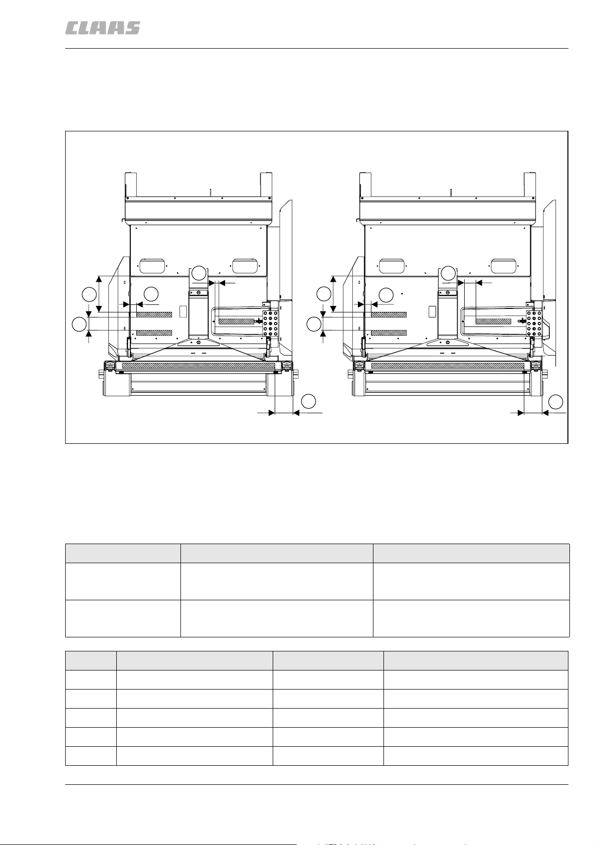
2.1.1 Replacing the HP feed rake conveyor anti-slip strips
2 Feed rake conveyor
2.1 Feed rake conveyor
82705
91711
A
Y
W
U
0° : 496 mm
+11° : 593 mm
Mass X für: -8° : 428 mm
X
W
U
X
V
B
Y
0° : 496 mm
+11° : 593 mm
Mass X für: -8° : 428 mm
V
31735
1
– Replace the anti-slip strips.
- Loosen the anti-slip strips (1) with a hot-air gun.
- Clean the base and ensure it is free of grease
and rust.
- Apply new anti-slip strips (1) to suit the dimensions and in parallel with one another.
Figure Designation Dimensions of anti-slip strips
A HP feed rake conveyor (1420 mm wide) 50 mm x 340 mm (3 pcs.)
B HP feed rake conveyor (1700 mm wide) 50 mm x 340 mm (3 pcs.)
Pos. Designation Dimensions Remarks
U Spacing dimension 64 mm
V Spacing dimension 177 mm
W Spacing dimension 350 mm
X Spacing dimension 125 mm
Y Spacing dimension 40 mm
00 0290 380 0 - ERG RHB LEXION 600-510 - 01/09 7
50 mm x 1470 mm (1 pc.)
50 mm x 1470 mm (1 pc.)
 Loading...