

Claas LEXION 600, LEXION 570, LEXION 550, LEXION 560, LEXION 540 Repair Manual Supplement
...
LEXION 560-510
LEXION 600-570
Repair manual
supplement

82703
!
s
n
o
i
t
c
u
r
t
s
n
i
y
t
e
f
a
s
e
h
t
P
l
e
a
s
e
w
o
l
l
o
f
d
n
a
d
a
e
r

Contents
1 Introduction
1.1 General information . . . . . . . . . . . . . . . . . . . . . . . . . . . . . . . . . . . . . . . . . . . . . . . . . . . . . . . . . . . . . . . 6
1.1.1 Validity of manual . . . . . . . . . . . . . . . . . . . . . . . . . . . . . . . . . . . . . . . . . . . . . . . . . . . . . . . . . . . . 6
2 Feed rake conveyor
2.1 Feed rake conveyor . . . . . . . . . . . . . . . . . . . . . . . . . . . . . . . . . . . . . . . . . . . . . . . . . . . . . . . . . . . . . . . 7
2.1.1 Replacing the HP feed rake conveyor anti-slip strips . . . . . . . . . . . . . . . . . . . . . . . . . . . . . . . . . 7
3 Straw discharge
3.1 Chaff spreader . . . . . . . . . . . . . . . . . . . . . . . . . . . . . . . . . . . . . . . . . . . . . . . . . . . . . . . . . . . . . . . . . . . 8
3.1.1 Overview of chaff spreader / chaff spreader fan LEXION 600 - 560 (type 589 - 584) . . . . . . . . 8
3.1.2 Overview of radial spreader LEXION 600 - 560 (type 589 - 584) . . . . . . . . . . . . . . . . . . . . . . . 10
3.2 Straw spreader . . . . . . . . . . . . . . . . . . . . . . . . . . . . . . . . . . . . . . . . . . . . . . . . . . . . . . . . . . . . . . . . . . 12
3.2.1 Overview of straw spreader . . . . . . . . . . . . . . . . . . . . . . . . . . . . . . . . . . . . . . . . . . . . . . . . . . . 12
4 Drives
4.1 Drive belts / drive chains . . . . . . . . . . . . . . . . . . . . . . . . . . . . . . . . . . . . . . . . . . . . . . . . . . . . . . . . . . 14
4.1.1 Drive diagram, left side (LEXION 600 with JET STREAM cleaning system) . . . . . . . . . . . . . . 14
4.1.2 Drive diagram, right side (LEXION 600 with JET STREAM cleaning system) . . . . . . . . . . . . . 16
4.1.3 Drive diagram, left side (LEXION 580 with standard cleaning system) . . . . . . . . . . . . . . . . . . 17
4.1.4 Drive diagram, right side (LEXION 580 with standard cleaning system) . . . . . . . . . . . . . . . . . 19
4.1.5 Drive diagram, left side (LEXION 570 with standard cleaning system) . . . . . . . . . . . . . . . . . . 21
4.1.6 Drive diagram, right side (LEXION 570 with standard cleaning system) . . . . . . . . . . . . . . . . . 23
4.1.7 Drive diagram, left side (LEXION 570 with JET STREAM cleaning system) . . . . . . . . . . . . . . 24
4.1.8 Drive diagram, right side (LEXION 570 with JET STREAM cleaning system) . . . . . . . . . . . . . 26
4.1.9 Drive diagram, left side (LEXION 560 - 510 with standard cleaning system) . . . . . . . . . . . . . . 28
4.1.10 Drive diagram, right side (LEXION 560 - 510 with standard cleaning system) . . . . . . . . . . . . . 30
4.1.11 Removing belt (R26) . . . . . . . . . . . . . . . . . . . . . . . . . . . . . . . . . . . . . . . . . . . . . . . . . . . . . . . . 31
4.1.12 Installing belt (R26) . . . . . . . . . . . . . . . . . . . . . . . . . . . . . . . . . . . . . . . . . . . . . . . . . . . . . . . . . . 32
4.1.13 Adjusting belt (R26) . . . . . . . . . . . . . . . . . . . . . . . . . . . . . . . . . . . . . . . . . . . . . . . . . . . . . . . . . 34
4.2 Fan drive of JET STREAM cleaning system LEXION 570 . . . . . . . . . . . . . . . . . . . . . . . . . . . . . . . . 35
4.2.1 Overview of fan variable-speed drive (electric) from serial no. ... . . . . . . . . . . . . . . . . . . . . . . . 35
4.2.2 Overview of fan variable-speed drive (spring-loaded) from serial no. ... . . . . . . . . . . . . . . . . . 37
4.2.3 Overview of fan variable-speed drive from serial no. ... . . . . . . . . . . . . . . . . . . . . . . . . . . . . . . 39
4.3 Special tool for fan drive of JET STREAM cleaning system LEXION 570 . . . . . . . . . . . . . . . . . . . 41
4.3.1 Disassembling the fan variable-speed drive (spring-loaded) from serial no. ... . . . . . . . . . . . . 41
4.3.2 Disassembling the fan variable-speed drive (spring-loaded) from serial no. ... . . . . . . . . . . . . 42
4.4 Front attachment drive . . . . . . . . . . . . . . . . . . . . . . . . . . . . . . . . . . . . . . . . . . . . . . . . . . . . . . . . . . . . 43
4.4.1 Overview of belt (R2) . . . . . . . . . . . . . . . . . . . . . . . . . . . . . . . . . . . . . . . . . . . . . . . . . . . . . . . . 43
4.4.2 Removing the drive pulley of belt (R2) from serial no. ... . . . . . . . . . . . . . . . . . . . . . . . . . . . . . 44
4.4.3 Overview of drive pulley of belt (R2) from serial no. ... . . . . . . . . . . . . . . . . . . . . . . . . . . . . . . . 45
4.4.4 Installing drive pulley of belt (R2) from serial no. ... . . . . . . . . . . . . . . . . . . . . . . . . . . . . . . . . . 46
4.4.5 Overview of belt (R3) (with front attachment variable-speed drive) . . . . . . . . . . . . . . . . . . . . . 47
4.4.6 Removing the front attachment variable-speed drive (hydraulic) from serial no. ... . . . . . . . . . 48
4.4.7 Overview of front attachment variable-speed drive (hydraulic) from serial no. ... . . . . . . . . . . . 49
4.4.8 Installing the front attachment variable-speed drive (hydraulic) from serial no. ... . . . . . . . . . . 50
4.4.9 Overview of belt (R3) (with front attachment step drive) . . . . . . . . . . . . . . . . . . . . . . . . . . . . . 52
4.4.10 Overview of belt (R26) . . . . . . . . . . . . . . . . . . . . . . . . . . . . . . . . . . . . . . . . . . . . . . . . . . . . . . . 53
82703
3

4.4.11 Removing drive pulley of belt (R26) . . . . . . . . . . . . . . . . . . . . . . . . . . . . . . . . . . . . . . . . . . . . . 54
4.4.12 Overview of drive pulley of belt (R26) . . . . . . . . . . . . . . . . . . . . . . . . . . . . . . . . . . . . . . . . . . . 55
4.4.13 Installing the drive pulley of belt (R26) . . . . . . . . . . . . . . . . . . . . . . . . . . . . . . . . . . . . . . . . . . . 56
4.4.14 Removing the driven pulley of belt (R26) . . . . . . . . . . . . . . . . . . . . . . . . . . . . . . . . . . . . . . . . . 56
4.4.15 Overview of driven pulley of belt (R26) . . . . . . . . . . . . . . . . . . . . . . . . . . . . . . . . . . . . . . . . . . 58
4.4.16 Installing the driven pulley of belt (R26) . . . . . . . . . . . . . . . . . . . . . . . . . . . . . . . . . . . . . . . . . . 59
4.4.17 Overview of jockey pulley of belt (R26) . . . . . . . . . . . . . . . . . . . . . . . . . . . . . . . . . . . . . . . . . . 60
4.5 Special tools for front attachment drive . . . . . . . . . . . . . . . . . . . . . . . . . . . . . . . . . . . . . . . . . . . . . 61
4.5.1 Installing drive pulley of belt (R2) from serial no. ... . . . . . . . . . . . . . . . . . . . . . . . . . . . . . . . . . 61
4.5.2 Removing the front attachment variable-speed drive (hydraulic) from serial no. ... . . . . . . . . . 62
4.5.3 Installing the front attachment variable-speed drive (hydraulic) from serial no. ... . . . . . . . . . . 63
4.5.4 Installing the drive pulley of belt (R26) . . . . . . . . . . . . . . . . . . . . . . . . . . . . . . . . . . . . . . . . . . . 64
4.5.5 Removing the driven pulley of belt (R26) . . . . . . . . . . . . . . . . . . . . . . . . . . . . . . . . . . . . . . . . . 65
4.5.6 Installing the driven pulley of belt (R26) . . . . . . . . . . . . . . . . . . . . . . . . . . . . . . . . . . . . . . . . . . 66
4.6 Impeller drive . . . . . . . . . . . . . . . . . . . . . . . . . . . . . . . . . . . . . . . . . . . . . . . . . . . . . . . . . . . . . . . . . . . 67
4.6.1 Removing the driven pulley of belt (R5) from serial no. ... . . . . . . . . . . . . . . . . . . . . . . . . . . . . 67
4.6.2 Overview of driven pulley of belt (R5) from serial no. ... . . . . . . . . . . . . . . . . . . . . . . . . . . . . . 68
4.6.3 Installing the driven pulley of belt (R5) from serial no. ... . . . . . . . . . . . . . . . . . . . . . . . . . . . . . 69
4.7 Special tool for impeller drive . . . . . . . . . . . . . . . . . . . . . . . . . . . . . . . . . . . . . . . . . . . . . . . . . . . . . . 70
4.7.1 Removing the driven pulley of belt (R5) from serial no. ... . . . . . . . . . . . . . . . . . . . . . . . . . . . . 70
82703
5 Axles, tyres
5.1 Steering Axle . . . . . . . . . . . . . . . . . . . . . . . . . . . . . . . . . . . . . . . . . . . . . . . . . . . . . . . . . . . . . . . . . . . 71
5.1.1 Removing the rear axle / CLAAS 4-Trac axle with standard cleaning system . . . . . . . . . . . . . 71
5.1.2 Installing the rear axle / CLAAS 4-Trac axle with standard cleaning system . . . . . . . . . . . . . . 73
5.1.3 Removing the rear axle / CLAAS 4-Trac axle / ACTIVE TRAC axle
with JET STREAM cleaning system . . . . . . . . . . . . . . . . . . . . . . . . . . . . . . . . . . . . . . . . . . . . 76
5.1.4 Installing the rear axle / CLAAS 4-Trac axle / ACTIVE TRAC axle
with JET STREAM cleaning system . . . . . . . . . . . . . . . . . . . . . . . . . . . . . . . . . . . . . . . . . . . . 78
5.1.5 Overview of rear axle (10 t, adjustable) . . . . . . . . . . . . . . . . . . . . . . . . . . . . . . . . . . . . . . . . . . 81
5.1.6 Overview of rear axle (9.5 t, adjustable) . . . . . . . . . . . . . . . . . . . . . . . . . . . . . . . . . . . . . . . . . 85
5.1.7 Overview of rear axle (9 t, adjustable) . . . . . . . . . . . . . . . . . . . . . . . . . . . . . . . . . . . . . . . . . . . 89
5.1.8 Overview of rear axle (9 t, rigid) . . . . . . . . . . . . . . . . . . . . . . . . . . . . . . . . . . . . . . . . . . . . . . . . 93
5.1.9 Overview of rear axle (8.5 t, adjustable) . . . . . . . . . . . . . . . . . . . . . . . . . . . . . . . . . . . . . . . . . 97
5.1.10 Overview of rear axle (7.5 t rigid / adjustable) . . . . . . . . . . . . . . . . . . . . . . . . . . . . . . . . . . . . 101
5.1.11 Overview of rear axle (7 t, adjustable) . . . . . . . . . . . . . . . . . . . . . . . . . . . . . . . . . . . . . . . . . . 105
5.2 Rear drive axle . . . . . . . . . . . . . . . . . . . . . . . . . . . . . . . . . . . . . . . . . . . . . . . . . . . . . . . . . . . . . . . . . 109
5.2.1 Removing the motor retainer of the ACTIVE TRAC axle (11 t) . . . . . . . . . . . . . . . . . . . . . . . 109
5.2.2 Overview of motor retainer of ACTIVE TRAC axle (11 t) . . . . . . . . . . . . . . . . . . . . . . . . . . . . . 111
5.2.3 Installing the motor retainer of ACTIVE TRAC axle (11 t) . . . . . . . . . . . . . . . . . . . . . . . . . . . .112
5.2.4 Removing the gearbox of ACTIVE TRAC axle (11 t) . . . . . . . . . . . . . . . . . . . . . . . . . . . . . . . .114
5.2.5 Installing the gearbox of ACTIVE TRAC axle (11 t) . . . . . . . . . . . . . . . . . . . . . . . . . . . . . . . . .115
5.2.6 Overview of ACTIVE TRAC axle (11 t) . . . . . . . . . . . . . . . . . . . . . . . . . . . . . . . . . . . . . . . . . .117
5.2.7 Overview of CLAAS 4-Trac axle (11 t) . . . . . . . . . . . . . . . . . . . . . . . . . . . . . . . . . . . . . . . . . . 121
5.2.8 Overview of CLAAS 4-Trac axle (9 t / 10 t) . . . . . . . . . . . . . . . . . . . . . . . . . . . . . . . . . . . . . . 125
5.2.9 Overview of CLAAS 4-Trac axle (9.5 t) . . . . . . . . . . . . . . . . . . . . . . . . . . . . . . . . . . . . . . . . . 129
5.3 Special tool for rear drive axle . . . . . . . . . . . . . . . . . . . . . . . . . . . . . . . . . . . . . . . . . . . . . . . . . . . . 133
5.3.1 Installing the motor retainer of ACTIVE TRAC axle (11 t) . . . . . . . . . . . . . . . . . . . . . . . . . . . 133
4

6 Hydraulic system
6.1 General . . . . . . . . . . . . . . . . . . . . . . . . . . . . . . . . . . . . . . . . . . . . . . . . . . . . . . . . . . . . . . . . . . . . . . . 134
6.1.1 Venting the hydrostatic system with mechano-hydraulic ground drive . . . . . . . . . . . . . . . . . . 134
6.1.2 Venting the hydrostatic system with electro-hydraulic ground drive . . . . . . . . . . . . . . . . . . . . 138
6.1.3 Venting the CLAAS 4-Trac system with mechano-hydraulic ground drive . . . . . . . . . . . . . . . 141
6.2 Special tool for general hydraulic system . . . . . . . . . . . . . . . . . . . . . . . . . . . . . . . . . . . . . . . . . . . 142
6.2.1 Venting the hydrostatic system with mechano-hydraulic ground drive . . . . . . . . . . . . . . . . . . 142
6.2.2 Venting the hydrostatic system with electro-hydraulic ground drive . . . . . . . . . . . . . . . . . . . . 142
6.3 Hydraulic motors . . . . . . . . . . . . . . . . . . . . . . . . . . . . . . . . . . . . . . . . . . . . . . . . . . . . . . . . . . . . . . . 143
6.3.1 Removing the radial spreader motor (241 / 242) . . . . . . . . . . . . . . . . . . . . . . . . . . . . . . . . . . 143
6.3.2 Installing the radial spreader motor (241 / 242) . . . . . . . . . . . . . . . . . . . . . . . . . . . . . . . . . . . 144
6.3.3 Removing the CLAAS 4-Trac axle motor (203 / 204) . . . . . . . . . . . . . . . . . . . . . . . . . . . . . . . 146
6.3.4 Installing the CLAAS 4-Trac axle motor (203 / 204) . . . . . . . . . . . . . . . . . . . . . . . . . . . . . . . . 149
6.3.5 Removing the motor of ACTIVE TRAC axle (2063 / 2064) . . . . . . . . . . . . . . . . . . . . . . . . . . 155
6.3.6 Installing the motor of ACTIVE TRAC axle (2063 / 2064) . . . . . . . . . . . . . . . . . . . . . . . . . . . 157
6.3.7 Overview of steering hydraulic cylinder (twin piston rod cylinder) (323) . . . . . . . . . . . . . . . . . 160
6.4 Special tool for hydraulic motors . . . . . . . . . . . . . . . . . . . . . . . . . . . . . . . . . . . . . . . . . . . . . . . . . . 162
6.4.1 Installing the radial spreader motor (241 / 242) . . . . . . . . . . . . . . . . . . . . . . . . . . . . . . . . . . . 162
6.5 Hydraulic cylinder . . . . . . . . . . . . . . . . . . . . . . . . . . . . . . . . . . . . . . . . . . . . . . . . . . . . . . . . . . . . . . . 163
6.5.1 Overview of steering hydraulic cylinder (twin piston rod cylinder) (323) . . . . . . . . . . . . . . . . . 163
82703
7 Engine
7.1 Transfer gearbox . . . . . . . . . . . . . . . . . . . . . . . . . . . . . . . . . . . . . . . . . . . . . . . . . . . . . . . . . . . . . . . . 165
7.1.1 Disassembling the transfer box . . . . . . . . . . . . . . . . . . . . . . . . . . . . . . . . . . . . . . . . . . . . . . . 165
7.1.2 Overview of transfer gearbox . . . . . . . . . . . . . . . . . . . . . . . . . . . . . . . . . . . . . . . . . . . . . . . . . 169
7.2 Special tool for transfer gearbox . . . . . . . . . . . . . . . . . . . . . . . . . . . . . . . . . . . . . . . . . . . . . . . . . . 174
7.2.1 Disassembling the transfer gearbox . . . . . . . . . . . . . . . . . . . . . . . . . . . . . . . . . . . . . . . . . . . . 174
7.2.2 Disassembling the transfer gearbox . . . . . . . . . . . . . . . . . . . . . . . . . . . . . . . . . . . . . . . . . . . . 175
7.2.3 Assembling the transfer gearbox . . . . . . . . . . . . . . . . . . . . . . . . . . . . . . . . . . . . . . . . . . . . . . 176
7.2.4 Assembling the transfer gearbox . . . . . . . . . . . . . . . . . . . . . . . . . . . . . . . . . . . . . . . . . . . . . . 177
5

1 Introduction
1.1 General information
1 Introduction
1.1 General information
1.1.1 Validity of manual
This manual applies only when used together with the
repair manual of the machine in question. The present
manual only includes the information deviating from
the original repair manual.
These instructions apply to the following machine /
front attachment:
Designation Type Serial number
From To
LEXION 600 589 58900011 –
LEXION 580 586 58600011 –
LEXION 570 585 58500011 –
82704
85574
LEXION 560 584 58400011 –
LEXION 550 584 58400011 –
LEXION 540 584 58400011 –
LEXION 540 C 584 58400011 –
LEXION 530 583 58300011 –
LEXION 520 583 58300011 –
LEXION 510 583 58300011 –
6 00 0290 380 0 - ERG RHB LEXION 600-510 - 01/09
2 Feed rake conveyor
2.1 Feed rake conveyor
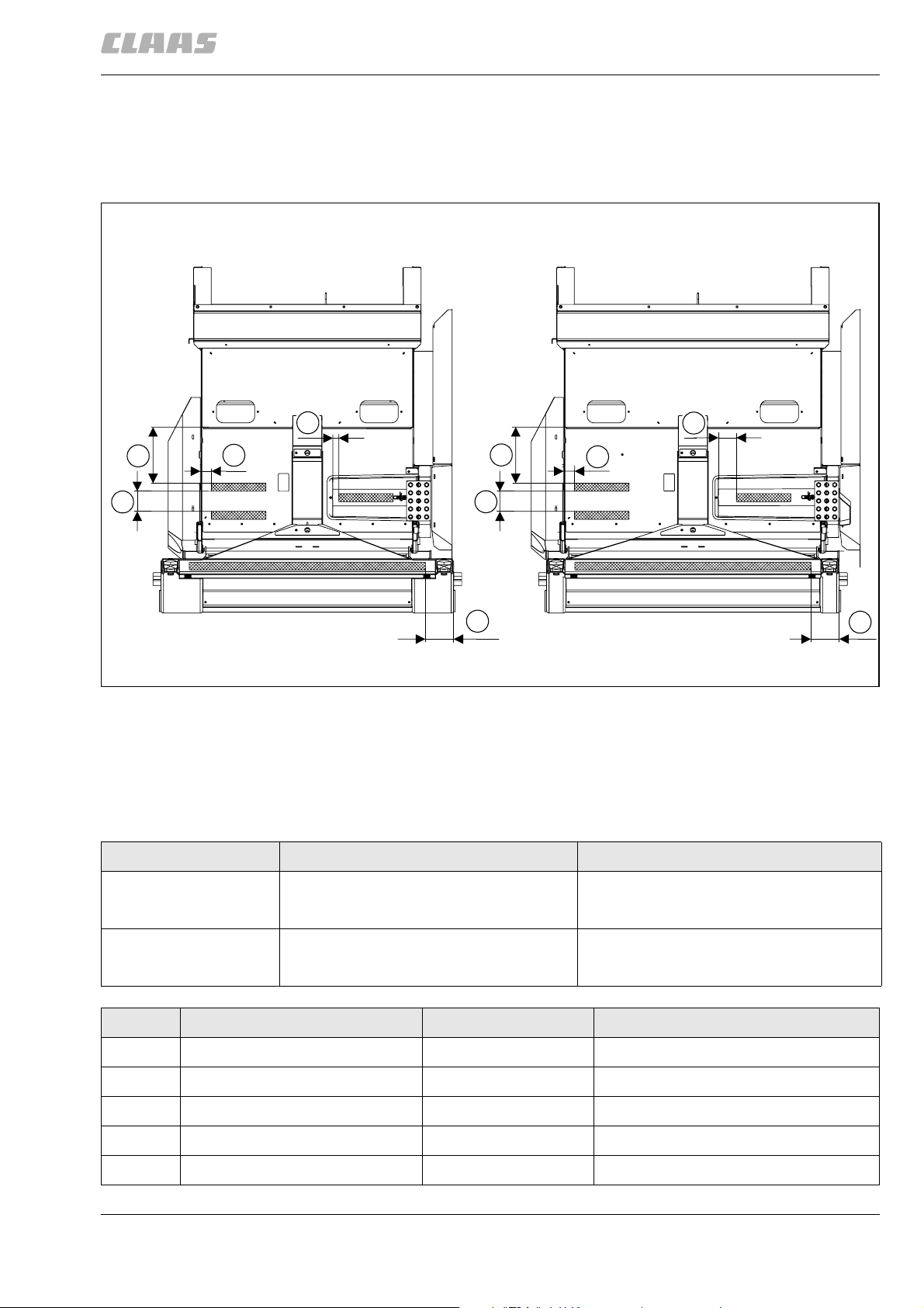
2.1.1 Replacing the HP feed rake conveyor anti-slip strips
2 Feed rake conveyor
2.1 Feed rake conveyor
82705
91711
A
Y
W
U
0° : 496 mm
+11° : 593 mm
Mass X für: -8° : 428 mm
X
W
U
X
V
B
Y
0° : 496 mm
+11° : 593 mm
Mass X für: -8° : 428 mm
V
31735
1
– Replace the anti-slip strips.
- Loosen the anti-slip strips (1) with a hot-air gun.
- Clean the base and ensure it is free of grease
and rust.
- Apply new anti-slip strips (1) to suit the dimensions and in parallel with one another.
Figure Designation Dimensions of anti-slip strips
A HP feed rake conveyor (1420 mm wide) 50 mm x 340 mm (3 pcs.)
B HP feed rake conveyor (1700 mm wide) 50 mm x 340 mm (3 pcs.)
Pos. Designation Dimensions Remarks
U Spacing dimension 64 mm
V Spacing dimension 177 mm
W Spacing dimension 350 mm
X Spacing dimension 125 mm
Y Spacing dimension 40 mm
00 0290 380 0 - ERG RHB LEXION 600-510 - 01/09 7
50 mm x 1470 mm (1 pc.)
50 mm x 1470 mm (1 pc.)

3 Straw discharge
3.1 Chaff spreader
3 Straw discharge
3.1 Chaff spreader
3.1.1 Overview of chaff spreader / chaff spreader fan LEXION 600 - 560 (type 589 - 584)
A
82706
86528
10
3
7
B
1
5
W
K
11
K
2
8
4
6
9
29610
1
Heading
A Overview of chaff spreader / chaff spreader
fan LEXION 600 - 560 (type 589 - 584)
B Removing / installing the chaff spreader drive
hydraulic motor (223)
8 00 0290 380 0 - ERG RHB LEXION 600-510 - 01/09

3 Straw discharge
3.1 Chaff spreader
82706
Pos. M
A
Auxiliary utilities Remarks
(Nm)
1 - 8 Multi-purpose grease, e.g.:
CLAAS AGRIGREASE EP 2,
Part no. 00 0147 437 0
Solid lubricant, e.g.:
MOLYKOTE G-n plus
Part no. 00 0177 571 0
9 Multi-purpose grease, e.g.:
CLAAS AGRIGREASE EP 2,
– Adjusting the torsional backlash (W):
- Unlock lock collars (1) and (2) and knock
them off.
- Slacken off hub (3).
- Loosen bolts (4).
- Adjust the torsional backlash (W) by relocating shaft (5) in the bearings and, if required,
by removing or adding shims (6).
- Check the contact pattern of the tooth flanks
with engineer's blue.
- Fix lock collars (1) and (2) by blows and
secure them.
- Bolt down hub (3).
- Tighten bolts (4).
Rub solid grease on bevel gears (7) and (8) and
apply some multi-purpose grease.
Fill lids (9) with 450 g of multi-purpose grease
each.
Part no. 00 0147 437 0
10, 11 7 Nm
M
= Tightening torque
A
Pos. Designation Dimensions Remarks
W Adjustment dimension (tor-
0.3-0.5mm
sional backlash)
00 0290 380 0 - ERG RHB LEXION 600-510 - 01/09 9

3 Straw discharge
3.1 Chaff spreader
3.1.2 Overview of radial spreader LEXION 600 - 560 (type 589 - 584)
82706
86806
B1
1
X
2
C
B2
3
C
A
Y
1
M
6
M
C
L
3
5
4
3
M
1
L
5
10 00 0290 380 0 - ERG RHB LEXION 600-510 - 01/09
29682
2

3 Straw discharge
3.1 Chaff spreader
Heading
A Overview of radial spreader
LEXION 600 - 560 (type 589 - 584).
B B1 = Removing / installing the left radial
spreader motor (241).
B2 = Removing / installing the right radial
spreader motor (242).
C Removing / disassembling / disassembled /
assembling / installing the chaff plate
adjustment hydraulic cylinder (3005).
82706
Pos. M
A
Auxiliary utilities Remarks
(Nm)
1, 2 Adjust deflector plates (1) to dimension (X) from the
roof panel (2).
Move the deflector plates (1) back and forth in front
of one another. Check the clearance (Y) over the
entire length here. The deflector plates (1) must not
touch one another!
3, 4, 5 Install the rubber paddle (3) so with clamping
sleeves that the thicker top layer (4) faces the
direction of rotation (observe the fabric insert)!
Install panhead screws (5) with new self-locking
nuts and the with the head in the direction of
rotation.
6 123 Nm
= Tightening torque
M
A
Pos. Designation Dimensions Remarks
X Adjustment dimension 10 mm
Y Checking dimension 6 mm
00 0290 380 0 - ERG RHB LEXION 600-510 - 01/09 11

3 Straw discharge
3.2 Straw spreader
3.2 Straw spreader
3.2.1 Overview of straw spreader
1
5
2
6
3
10
9
B
82706
86944
A
7
4
8
13
15
14
13
11
X
16
17
C
12
29727
12 00 0290 380 0 - ERG RHB LEXION 600-510 - 01/09
3

3 Straw discharge
3.2 Straw spreader
82706
Heading
A Overview of straw spreader.
B Removing / installing the straw spreader drive
hydraulic motor (223).
C Removing / installing / adjusting belt (R17).
Pos. M
A
Auxiliary utilities Remarks
(Nm)
1 - 8 90 Nm – Removing / installing toothed belt pulleys
(5 - 8):
- Remove belt (R17).
- Unscrew tensioning screws (1 - 4).
- Screw tensioning screws (1 - 4) into the free
tapped holes until the lock collars are slackened off.
- Pull off toothed belt pulleys (5 - 8).
- Clean toothed belt pulleys (5 - 8), the lock
collars and the shaft ends so they are free of
grease.
- Pre-assemble toothed belt pulleys (5 - 8)
with lock collars and slide them on the shaft
ends.
- Align toothed belt pulleys (5 - 8) towards
one another, using a ruler.
- Arrest lock collars with tensioning screws
(1 - 4).
Tightening torque = 90 Nm
- Install and adjust belt (R17).
9 130 Nm
10, 11 40 Nm
12 Silicone sealing compound, e.g.:
Seal corners (12) with silicone sealing compound.
Silicone rubber
Part no. 00 0136 544 0
13, 14 Adjust dimension (X) between belt and ball bearing
(13) at the eccentric (14) with belt (R17) tensioned.
15, 16,
17
Install brackets (15) with an offset dimension (Y)
between them.
Check free rotation of wings (16) and (17).
M
= Tightening torque
A
Pos. Designation Dimensions Remarks
X Adjustment dimension 1.2 mm
Y Adjustment dimension 60°
00 0290 380 0 - ERG RHB LEXION 600-510 - 01/09 13

4 Drives
4.1 Drive belts / drive chains
4 Drives
4.1 Drive belts / drive chains
4.1.1 Drive diagram, left side (LEXION 600 with JET STREAM cleaning system)
82707
15176
R1
R2
R3
K11
R5
R6
R9
R7
R4
R8
R21
R10
R18
R12
R26
R3
R13
R14
R25
R17
Designation
R1 Feed rake conveyor suction blower drive
R2 Front attachment drive, 2nd step (without variable-speed drive)
R3 Front attachment drive, 3rd step (with variable-speed drive or step drive)
R4 Front attachment variable-speed drive, 2nd step
R5 Impeller drive
R6 Reel hydraulic pump drive
R7 Front attachment drive, 1st step
R8 Straw spreader, chaff spreader and radial spreader hydraulic pump drive
R9 Threshing mechanism drive
R10 Grain tank unloading drive, 1st step
K11 Grain tank unloading drive, 2nd step
R12 Straw chopper drive, 1st step
R13 Straw chopper drive, 2nd step
R14 Straw chopper drive, 3rd step
6200
1
D = Threshing drum, V = Accelerator, W = Impeller, R = Drive belts, K = Drive chains
14 00 0290 380 0 - ERG RHB LEXION 600-510 - 01/09

4.1 Drive belts / drive chains
Designation
R17 Straw spreader drive
R18 Sieve pan drive, 1st step
R21 Sieve pan drive, 3rd step
R25 Sieve pan drive, 2nd step
R26 Front attachment step drive, 2nd step
D = Threshing drum, V = Accelerator, W = Impeller, R = Drive belts, K = Drive chains
4 Drives
82707
00 0290 380 0 - ERG RHB LEXION 600-510 - 01/09 15

4 Drives
4.1 Drive belts / drive chains
4.1.2 Drive diagram, right side (LEXION 600 with JET STREAM cleaning system)
R41
K62
K64
82707
91456
R40
R42
R61 R60
Designation
R40 Axial rotor step drive, step 2
R41 Axial rotor variable-speed drive, step 2
R42 Axial rotor drive, step 1
R47 Fan drive, step 1
R47
R63
R49
R50
R52
R53
K55
R54
6201
2
R49 Fan variable-speed drive, step 2
R50 Fan drive, step 3
R52 Threshing mechanism variable-speed drive
R53 Threshing drum drive
R54 Accelerator drive
K55 Returns auger drive
R60 A/C compressor drive and water pump drive
R61 3-phase alternator / fan drive
K62 Planar rotary chaff screen suctioning system nozzle
R63 Planar rotary chaff screen suction system fan
K64 Grain tank filler auger drive
D = Threshing drum, V = main intermediate drive shaft, T = Accelerator,
R = Drive belts, K = Drive chains
16 00 0290 380 0 - ERG RHB LEXION 600-510 - 01/09

4.1.3 Drive diagram, left side (LEXION 580 with standard cleaning system)
4 Drives
4.1 Drive belts / drive chains
82707
91458
R1
R3
R2
K11
R5
R6
R9
R7
R4
R8
R10
R18
R20
R3
R12
R19
R20R23
R26
R13
R14
R24
R17
R15
R16
Designation
R1 Feed rake conveyor suction blower drive
R2 Front attachment drive, step 2 (without variable-speed drive)
R3 Front attachment drive, step 3 (with variable-speed drive or step drive)
R4 Front attachment variable-speed drive, step 2
R5 Impeller drive
R6 Reel hydraulic pump drive
R7 Front attachment drive, step 1
R8 Hydraulic pump drive for straw spreader, chaff spreader, radial spreader
R9 Threshing mechanism drive
R10 Grain tank unloading drive, step 1
K11 Grain tank unloading drive, step 2
R12 Straw chopper drive, step 1
R13 Straw chopper drive, step 2
R14 Straw chopper drive, step 3
3639
3
R17 Straw spreader drive
R18 Sieve pan drive, step 1
D = Threshing drum, V = Accelerator, W = Impeller, R = Drive belt, K = Drive chains
00 0290 380 0 - ERG RHB LEXION 600-510 - 01/09 17

4 Drives
4.1 Drive belts / drive chains
Designation
R20 Sieve pan drive, step 3
R23 Feed pan drive, step 1
R24 Feed pan drive, step 2
R26 Front attachment step drive, step 2
D = Threshing drum, V = Accelerator, W = Impeller, R = Drive belt, K = Drive chains
82707
18 00 0290 380 0 - ERG RHB LEXION 600-510 - 01/09

4.1 Drive belts / drive chains
4.1.4 Drive diagram, right side (LEXION 580 with standard cleaning system)
4 Drives
82707
91460
R41
R40
R42
R61
K62
R60R61
R63
R46
R51
R60
R57
K56
R48
R52
K55
R53
R54
Designation
R40 Axial rotor step drive, step 2
R41 Axial rotor variable-speed drive, step 2
R42 Axial rotor drive, step 1
R46 Fan drive, step 1
R48 Fan variable-speed drive, step 2
R51 Rotary chaff screen suction blower drive
R52 Threshing mechanism variable-speed drive
R53 Threshing drum drive
R54 Accelerator drive
K55 Returns auger drive
K56 Grain tank filler auger drive
R57 Rotary chaff screen drive
R60 A/C compressor drive and water pump drive
R61 Three-phase alternator drive, fan drive
10306
4
K62 Planar rotary chaff screen suctioning system nozzle
D = Threshing drum, V = main intermediate drive shaft, T = Accelerator,
R = Drive belts, K = Drive chains
00 0290 380 0 - ERG RHB LEXION 600-510 - 01/09 19

4 Drives
4.1 Drive belts / drive chains
Designation
R63 Planar rotary chaff screen suction system fan
R60 A/C compressor drive and water pump drive
R61 3-phase alternator / fan drive
K62 Planar rotary chaff screen suctioning system nozzle
R63 Planar rotary chaff screen suction system fan
K64 Grain tank filler auger drive
D = Threshing drum, V = main intermediate drive shaft, T = Accelerator,
R = Drive belts, K = Drive chains
82707
20 00 0290 380 0 - ERG RHB LEXION 600-510 - 01/09

 Loading...