

Page 1

LEXION 470 - 420 Montana
Technical
Systems
Electric/Hydraulic
System
Supplement
Page 2

Electric System LEXION-Montana TIC
Page 3

TIC LEXION-Montana Electric System
The present document exclusively describes all special electric and hydraulic
functions of the LEXION Montana series.
Explanations and descriptions concerning the basic machine and the front attachments
can be found in the relevant Electric System (297 550.x) and Hydraulic System
(297 549.x) documents.
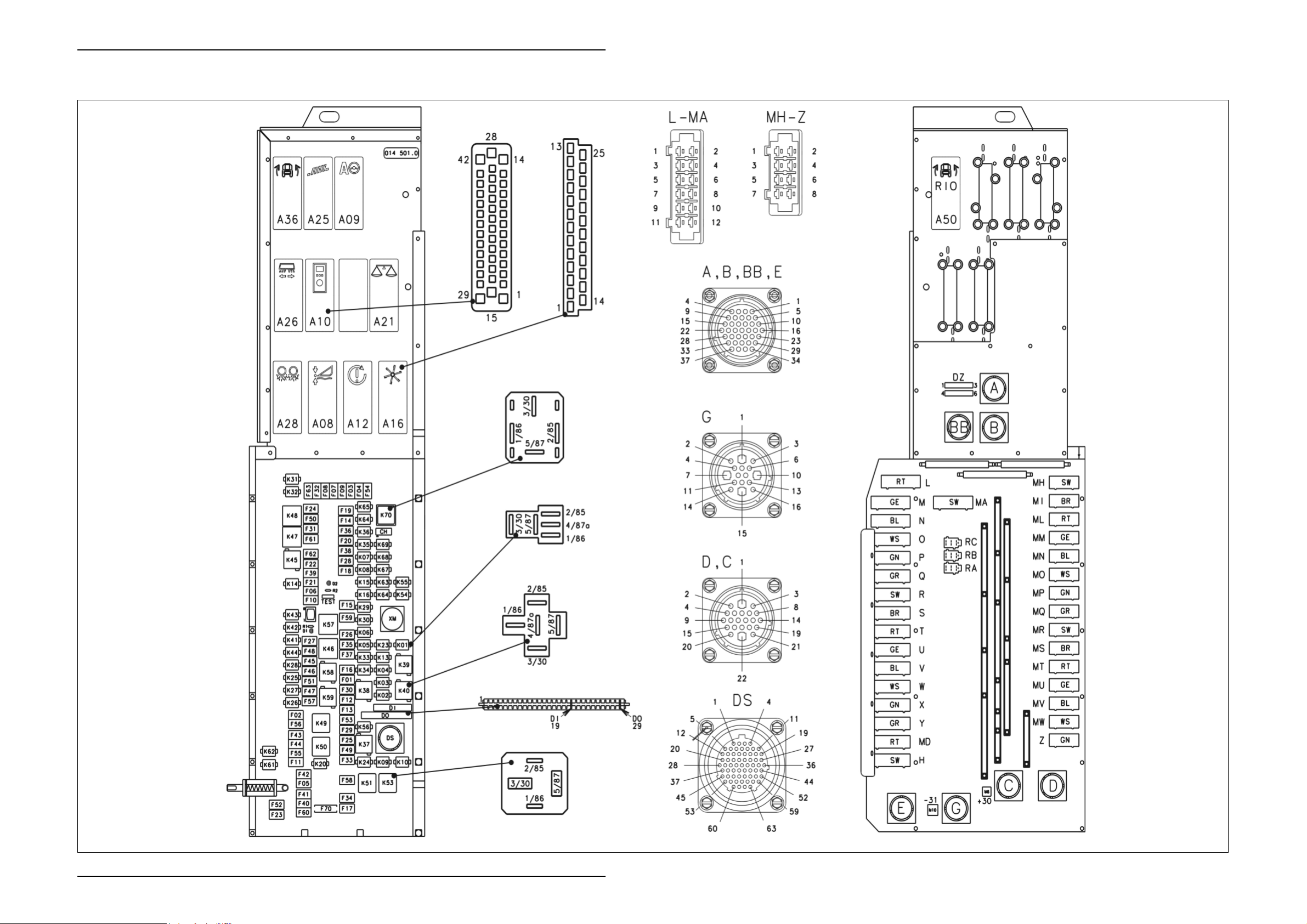
D-S - Central terminal compartment on Montana machines 014 501.0
(with RIO module A50) ................................................................................. ZE-s-2
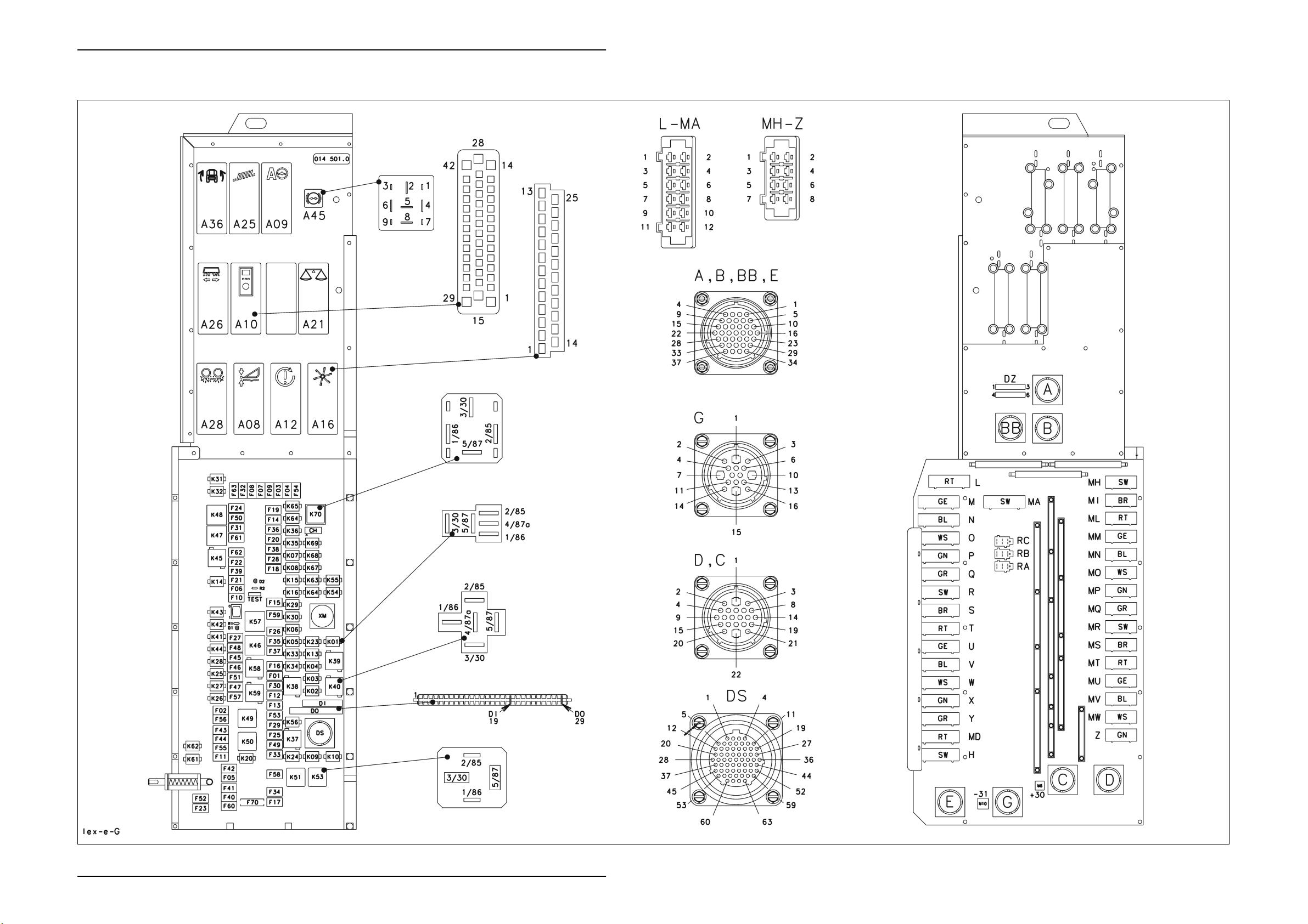
D-S - Central terminal compartment on Montana machines 014 501.0
(with HBM module A45) ............................................................................... ZE-s-4
Module A35 - Montana control unit, for Montana machines
(with RIO module A50) ................................................................................. ZE-s-9
Module A35 - Montana control unit, for Montana machines
(with HBM module A45) ............................................................................. ZE-s-10
Module A36 - Montana gearshift module.................................................................. ZE-s-11
Module A45 - Ground drive hydraulic motor brake restrictor (HBM) ......................... ZE-s-12
Module A50 - Montana RIO module ......................................................................... ZE-s-12
01s - Main power supply, diesel engine electric starting motor,
for Montana machines.................................................................................... 01s-2
02s - Starting the diesel engine, diesel engine speed adjustment
- for Montana machines.................................................................................. 02s-2
04s - Road travel activation, working hydraulics master valve,
for Montana machines with module A50 (RIO)............................................... 04s-2
04t - Road travel activation, working hydraulics master valve,
for Montana machines with module A45 (HBM) ..............................................04t-2
05s - Terminal, keyboard, rotary switch, printer,
for Montana machines with module A50 (RIO)............................................... 05s-2
05t - Terminal, keyboard, rotary switch, printer,
for Montana machines with module A45 (HBM) ..............................................05t-2
06s - CAN bus, module power supply,
for Montana machines with module A50 (RIO)............................................... 06s-2
06t - CAN bus, module power supply,
for Montana machines with module A45 (HBM) ..............................................06t-2
Page 4

Electric System LEXION-Montana TIC
Page 5

TIC LEXION-Montana Electric System
17s - Front attachment drive, reverser drive for Montana machines ....................... 17s-2
20s - Raise / lower front attachment, cross levelling – for Montana machines........ 20s-2
26s - Machine monitoring, for Montana machines................................................... 26s-2
41s - Axle control system and front attachment control system,
for Montana machines with module A50 (RIO)............................................... 41s-2
41t - Axle control system and front attachment control system,
for Montana machines with module A45 (HBM) ..............................................41t-2
42s - Ground drive and brake control,
for Montana machines with module A50 (RIO)............................................... 42s-2
42t - Ground drive and brake control,
for Montana machines with module A45 (HBM) ..............................................42t-2
Index .................................................................................................................... Index-3
Page 6

Electric System LEXION-Montana TIC
Page 7

D-S
Central terminal compartment
014 501.0
Montana (with RIO module A50)
Page 8
Electric System LEXION Montana TIC
D-S - Central terminal compartment on Montana machines
014 501.0 (with RIO module A50)
ZE-s-2 Lex-e-ZE 03/04
Page 9

D-S
Central terminal compartment
014 501.0
Montana (with HBM module A45)
Page 10
Electric System LEXION Montana TIC
D-S - Central terminal compartment on Montana machines
014 501.0 (with HBM module A45)
ZE-s-4 Lex-e-ZE 03/04
Page 11

TIC LEXION Montana Electric System
Key to diagram:
A08 AUTOCONTOUR module (CAC)
A09 AUTOPILOT module
A10 Fieldwork computer module (BIF/CAB)
A12 Speed monitor module (DZW)
A16 Reel controller module (HAS)
A21 YIELD METER module (LEM)
A25 Sieve adjustment module
A26 Deflector adjustment module
A28 Uni-spreader module (VGS)
A36 Electro-hydraulic gearshift module
A45 Ground drive hydraulic motor brake restrictor module (HBM)
A50 RIO module (ground drive hydraulic motor brake restrictor)
DI Warning device diode PCB
D0 Master valve diode PCB
DS Diagnosis (63-pin) VIA
F1
F2
F3
F4
F5
F6
F7
F8
F9
F10
F11
F12
F13
F14
F15
F16
F17
F18
F19
F20
F21
F22
F23
F24
F25
F26
F27
F28
F29
F30
F31
F32
F33
F34
F35
Modules
Electronic components
Fuses
Dipped headlights circuit
Sieve adjustment module 12 V control unit
CAN connection of performance monitor
+12 V electronic unit
12 V air conditioner fan
##
CAC module
Reel module
Yield meter
Yield meter
Inside work lights
Work lights
Cigarette lighter
Seat socket
Drum/rotor speed adjustment
Concave adjustment
Diagnosis LED
Cutterbar
Engine speed switch
All-wheel drive 12 V switch
Threshing mechanism relay
Fan speed relay
Hazard warning switch 30
Hazard warning switch 15
Fan speed relay
Reel controller
Upper/lower sieve
Autopilot switch
12 V / K56 pin 30
Brake light switch 12 V / Sieve pan light
12 V IMO
12 V IMO
Air conditioner relay
Engine control unit 12 V power supply
CAC module / VGS module
03/04 Lex-e-ZE ZE-s-5
Page 12

Electric System LEXION Montana TIC
Key to diagram:
Fuses
F36
Grain tank extension
12 V grain tank drive
F37
F38
Work light
F39
Chopper On/Off pushbutton
F40
Vehicle lighting switch 12 V
F41
Warning beacon
12 V horn / wiper and washer system
F42
F43
Position light, left-hand
F44
Position light, right-hand
F45
Left-hand full beam relay
F46
Left-hand dipped beam relay
F47
Right-hand full beam relay
Right-hand dipped beam relay
F48
F49
Table adjustment
F50
Grain tank extension
F51
Ignition diagnosis plug
F52
Instrument lighting
F53
Returns lighting
Uni-spreader/Autopilot module
F54
F55
Worklight switch
F56
Spare module
F57
Spare module
F58
Spare (connector H)
Engine diagnosis
F59
F60
12 V sockets LP/HP
F61
###
F62
Outside railing worklights relay
F63
12 V sensors power supply
F64
###
###
F65
F70
Ignition switch back-up fuse
ZE-s-6 Lex-e-ZE 03/04
Page 13

TIC LEXION Montana Electric System
Key to diagram:
K1
K2
K3
K4
K5
K6
K7
K8
K9
K10
K13
K14
K15
K16 Cutterbar
K20
K23
K24
K25
K26
K27
K28
K29 Drum speed adjustment relay
K30 Drum speed adjustment relay
K31
K32
K33 Concave clearance +
K34 Concave clearance K35 Front attachment speed +
K36 Front attachment speed K37
K38
K39 Reel speed K40 Reel speed +
Relays
Raise reel
Lower reel
Reel forward
Reel backward
Raise cutterbar
Lower cutterbar
Cutterbar left-hand cross levelling
Cutterbar right-hand cross levelling
Table adjustment forward
Table adjustment backward
Threshing mechanism On/Off
Threshing mechanism On/Off
Cutterbar
Lighting main relay
Alternator
Air conditioner relay
Left-hand full beam relay
Right-hand full beam relay
Left-hand dipped beam relay
Right-hand dipped beam relay
Grain tank extension up
Grain tank extension down
Fan speed +
Fan speed -
03/04 Lex-e-ZE ZE-s-7
Page 14

Electric System LEXION Montana TIC
Key to diagram:
K41
K42
K43
K44
K45
K46
K47
K48
K49
K50
K51
K53
K54
K55
K56
K57
K58
K59
K61
K62
K63
K64 Reel speed relay
K67
K68
K69
K70 Grain tank unloading relay
Relays
Upper sieve adjustment -
Upper sieve adjustment +
Lower sieve adjustment -
Lower sieve adjustment +
Work lights
Grain tank unloading tube swing time relay
Flash relay USA
Indicator relay Europe
Road travel main relay
Work lights relay
Relay 15
Start relay
Rotor variator +
Rotor variator -
Plus 15 power supply
Transducer
Alternator relay
Work lights relay
Warning beacon
Warning beacon grain tank 70% full
Fan speed relay
Spare relay
Spare relay
Spare relay
ZE-s-8 Lex-e-ZE 03/04
Page 15

TIC LEXION Montana Electric System
Module A35 - Montana control unit, for Montana machines (with RIO module A50)
Pin Function Component Measuring
variable
1 Earth A41 Earth Output 05S
2 CAN Low Montana A41 - Output 05S
3 CAN High Montana A41 - Output 05S
4 Power supply (CAN) A41 12 V Output 05S
5 not used --- --- --- ---
6 Parking brake signal S93 12 V Input 41S
7 Montana cross levelling sensor signal B94 0.25-4.75 V Input 41S
8 Montana feed rake conveyor sensor signal B95 0.25-4.75 V Input 41S
9 Right-hand axle angle sensor signal B92 0.25-4.75 V Input 41S
10 not used --- --- --- ---
11 Oil quantity increase Y118 12 V Output 41S
12 Master valve (Montana) Y128 12 V Output 4S, 4t
13 Lower axle, right-hand side Y116 12 V Output 41S
14 Raise axle, right-hand side Y117 12 V Output 41S
15 Rotate front attachment to the right Y112 12 V Output 41S
16 Lower cutting angle Y111 12 V Output 41S
17 Power supply (K69) --- 12 V Input 41S, 4S
18 Power supply (K69) --- 12 V Input 41S, 4S
19 RS 232 --- --- --- 05S
20 RS 232 --- --- --- 05S
21 RS 232 --- --- --- 05S
22 RS 232 (Boot) --- --- --- 05S
23 not used --- --- --- ---
24 Earth sensors B91, B92,
B93, B94,
B95
25 Cutting angle sensor signal B93 0.25-4.75 V Input 41S
26 Left-hand axle angle sensor signal B91 0.25-4.75 V Input 41S
27 Power supply of sensors B91, B92,
B93, B94,
B95
28 not used --- --- --- ---
29 Master valve (Working hydraulics) Y77 12 V Output 4S
30 Lower axle, left-hand side Y114 12 V Output 41S
31 Raise axle, left-hand side Y115 12 V Output 41S
32 Rotate front attachment to the left Y113 12 V Output 41S
33 Raise cutting angle Y110 12 V Output 41S
34 Earth --- Earth Input 41S, 4S
35 Earth --- Earth Input 41S, 4S
Earth Output 41S
12 V Output 41S
Direction Circuit
diagram no.
03/04 Lex-e-ZE ZE-s-9
Page 16

Electric System LEXION Montana TIC
Module A35 - Montana control unit, for Montana machines (with HBM module A45)
Pin Function Component Measuring
variable
1 Power supply (K69) --- 12 V Input 41t, 4t
2 Lower axle, left-hand side Y114 12 V Output 41t
3 Raise axle, left-hand side Y115 12 V Output 41t
4 Raise axle, right-hand side Y117 12V Output 41t
5 Lower axle, right-hand side Y116 12 V Output 41t
6 Rotate front attachment to the left Y113 12 V Output 41t
7 Rotate front attachment to the right Y112 12 V Output 41t
8 Raise cutting angle Y110 12 V Output 41t
9 Lower cutting angle Y111 12 V Output 41t
10 Master valve (Montana) Y128 12 V Output 4t
11 Master valve (Working hydraulics) Y77 12 V Output 4t
12 Oil quantity increase Y118 12 V Output 41t
13 not used --- --- --- ---
14 Earth --- Earth Input 41t
15 Power supply (K69) --- 12 V Input 41t, 4t
16 Left-hand axle angle sensor signal B91 0.25-4.75 V Input 41t
17 Montana cross levelling sensor signal B94 0.25-4.75 V Input 41t
18 not used --- --- --- ---
19 not used --- --- --- ---
20 not used --- --- --- ---
21 CAN Low (Inclinometer) B126 - Output 05t
22 not used --- --- --- ---
23 CAN Low (Montana) A41 - Output 05t
24 Earth A41 Earth Output 05t
25 RS 232 --- --- --- 05t
26 RS 232 --- --- --- 05t
27 not used --- --- --- ---
28 Earth --- Earth Input 41t
29 Power supply (K69) --- 12 V Input 4t
30 Right-hand axle angle sensor signal B92 0.25-4.75 V Input 41t
31 Cutting angle sensor signal B93 0.25-4.75 V Input 41t
32 Parking brake signal S93 12V Input 41t
33 Earth sensors B91, B92,
B93, B94,
B95, B126
34 not used --- --- --- ---
35 not used --- --- --- ---
36 CAN High (Inclinometer) B126 - Output 05t
37 Power supply (CAN) A41 12 V Output 05t
38 CAN High (Montana) A41 - Output 05t
39 RS 232 (Boot) --- --- --- 05t
40 RS 232 --- --- --- 05t
41 not used --- --- --- ---
42 not used --- --- --- ---
Earth Output 41t
Direction Circuit
diagram no.
ZE-s-10 Lex-e-ZE 03/04
Page 17

TIC LEXION Montana Electric System
Module A36 - Montana gearshift module
Pin Function Component Measuring
variable
1 Earth --- Earth Input 42s, 42t
2 Power supply (+15) K56 12 V Input 42s, 42t
3 Gearbox shifting release S90 12 V Output 42s, 42t
4 2nd gear signal Z83 12 V Input 42s, 42t
5 1st gear signal Z82 12 V Input 42s, 42t
6 Gearbox shift 1st gear Y107 12 V Output 42s, 42t
7 Gearbox shift 2nd gear Y108 12 V Output 42s, 42t
8 Ground speed control lever neutral signal Z57 Earth Input 1s;42s, 42t
9 Ground drive control pressure circuit SH Y125 12 V Output 42s, 42t
10 Engine speed maximum
reduced
--- 12 V – 1st gear
0 V – 2
nd
gear
11 Engine speed (Gearshift control) --- 12 V Input 42s, 42t
12 Parking brake circuit Y123 12 V Input 42s, 42t
13 Shifting aid uphill signal Y121 12 V Input 42s, 42t
14 Shifting aid downhill signal Y122 12 V Input 42s, 42t
15 Working hydraulics master valve Y77 12 V Output 4s, 4t
16 Working hydraulics master valve Y77 12 V Output 4s, 4t
17 Montana master valve Y128 12 V Output 4s, 4t
18 Montana master valve Y128 12 V Input 4s, 4t
19 Montana master valve Y128 12 V Input 4s
20 Working hydraulics master valve Y77 12 V Input 4s, 4t
21 Working hydraulics master valve Y77 12 V Input 4s, 4t
22 Working hydraulics master valve Y77 12 V Input 4s, 4t
23 Working hydraulics master valve Y77 12 V Input 4s, 4t
24 Shifting aid Y121; Y122 12 V Output 42s, 42t
25 not used --- --- --- ---
Direction Circuit
diagram no.
Output 42s, 42t
03/04 Lex-e-ZE ZE-s-11
Page 18

Electric System LEXION Montana TIC
Module A45 - Ground drive hydraulic motor brake restrictor (HBM)
Pin Function Component Measuring
variable
1 --- --- --- --- ---
2 Master valve Y77 12 V Output 42t
3 CAN high - - - 6t
4 Power +15 K51/87 12 V Input 6t
5 --- --- --- --- ---
6 Earth (GND) -31 Earth Input 6t
7 --- --- --- --- ---
8 Brake restrictor Y124 12 V Output 42t
9 CAN low - - - 6t
Module A50 - Montana RIO module
Pin Function Component Measuring
variable
R0/1 +12 V electronic unit --- --- --- ---
R0/2 +12 V power --- --- --- ---
R0/3 Output 1 Montana master valve Y128 12 V Output 4s, 42s
R0/4 Ground drive hydraulic motor brake
restrictor (output 3)
R0/5 Working hydraulics
master valve output 2
R0/6 Output 4 --- --- --- ---
R0/7 Sensor 1 --- --- --- ---
R0/8 Sensor 2 --- --- --- ---
R0/9 Earth --- --- --- ---
R0/10 Earth --- --- --- ---
R0/11 Module code 1 --- --- --- ---
R0/12 Module code 2 --- --- --- ---
R0/13 Module code 3 --- --- --- ---
R0/14 Module code 4 --- --- --- ---
R0/15 Sensor 3 --- --- --- ---
R0/16 Sensor 4
R1/1 CAN low --- --- --- 6s
R1/2 +12 V electronic unit --- 12 V Input 2s, 6s
R1/3 +12 V power --- 12 V Input 2s, 6s
R1/4 CAN high --- --- --- 6s
R1/5 Earth --- Earth Input 6s
R1/6 Earth --- Earth Input 6s
Y124 12 V Output 42s
Y77 12 V Output 4s, 42s
Direction Circuit
diagram no.
Direction Circuit
diagram no.
ZE-s-12 Lex-e-ZE 03/04
Page 19

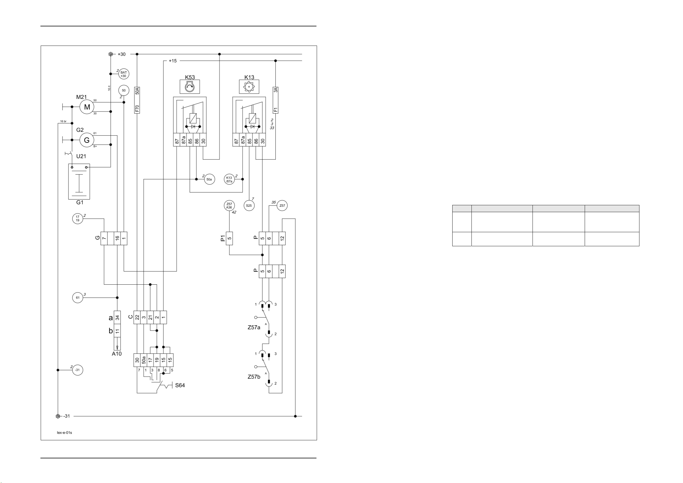
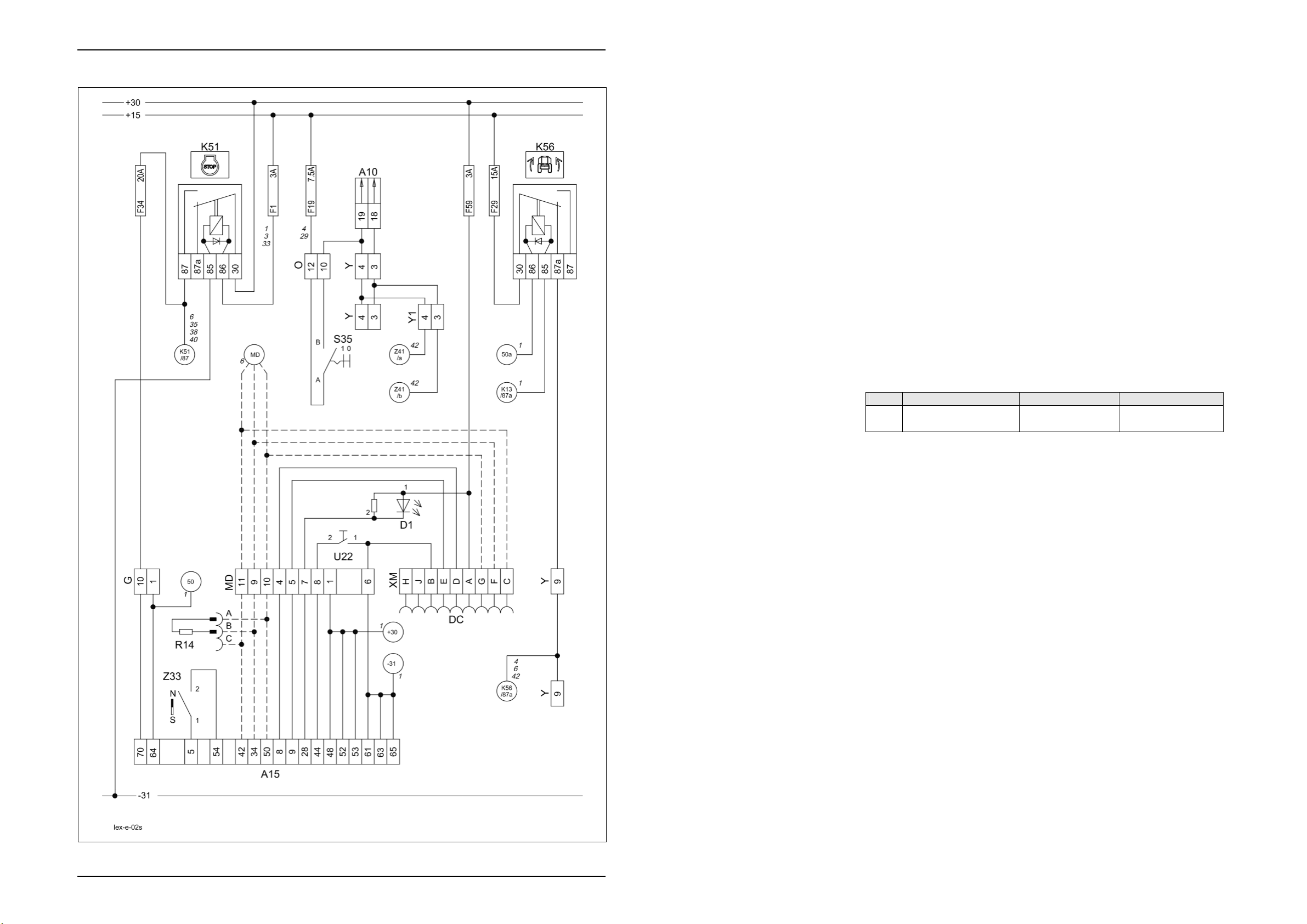
01s
Main power supply,
Diesel engine electric starting motor
for Montana machines
Page 20
Electric System LEXION Montana TIC
01s - Main power supply, diesel engine electric starting motor, for Montana machines
Key to diagram:
Coordinates
A10 Fieldwork computer module (BIF/CAB) ............................. 2-h-20
G1 Battery................................................................................ 7-n-21
G2 Generator........................................................................... 1-g-17
K13 Threshing mechanism relay............................................... 3-h-20
K53 Start relay........................................................................... 3-h-20
M21 Electric starting motor ........................................................ 3-n-19
S64 Ignition switch ..................................................................... 3-f-18
U21 Battery isolating switch ...................................................... 6-o-20
Z57 Ground speed control lever
neutral position switch - safety start switch ....................... 3-g-18
Measured value table:
Item Component Measured value Remark
K13 Remote control relay
15 A
30 A
K53 Remote control relay
70 A
95±10 Ω
115±10 Ω
(Pin 86/1 – 85/2)
(Pin 87a/4 – 30/3)
(Pin 87/5 – 30/3)
(Pin 86/1 – 85/2)
(Pin 87/5 – 30/3)
1s-2 Lex-e-01s 03/04
Page 21

TIC LEXION-Montana Electric System
Description of function:
Montana machine: In this circuit, the difference between the standard machine and the
Diesel engine electric
starting motor
Montana machine is only in a cable branch at connector P to P1. The
signal of ground speed control lever in neutral position (Z57) is required
on Montana machines for releasing the gear shifting.
As a safety start switch, relay K53 is supplied with earth only when
switches (Z57a/Z57b) on the ground speed control lever are in neutral
position and the threshing mechanism is disengaged via relay K13. The
ignition lock (S64) then actuates the diesel engine starting motor (M21)
via relay K53 with +50a.
03/04 Lex-e-01s 1s-3
Page 22
Electric System LEXION Montana TIC
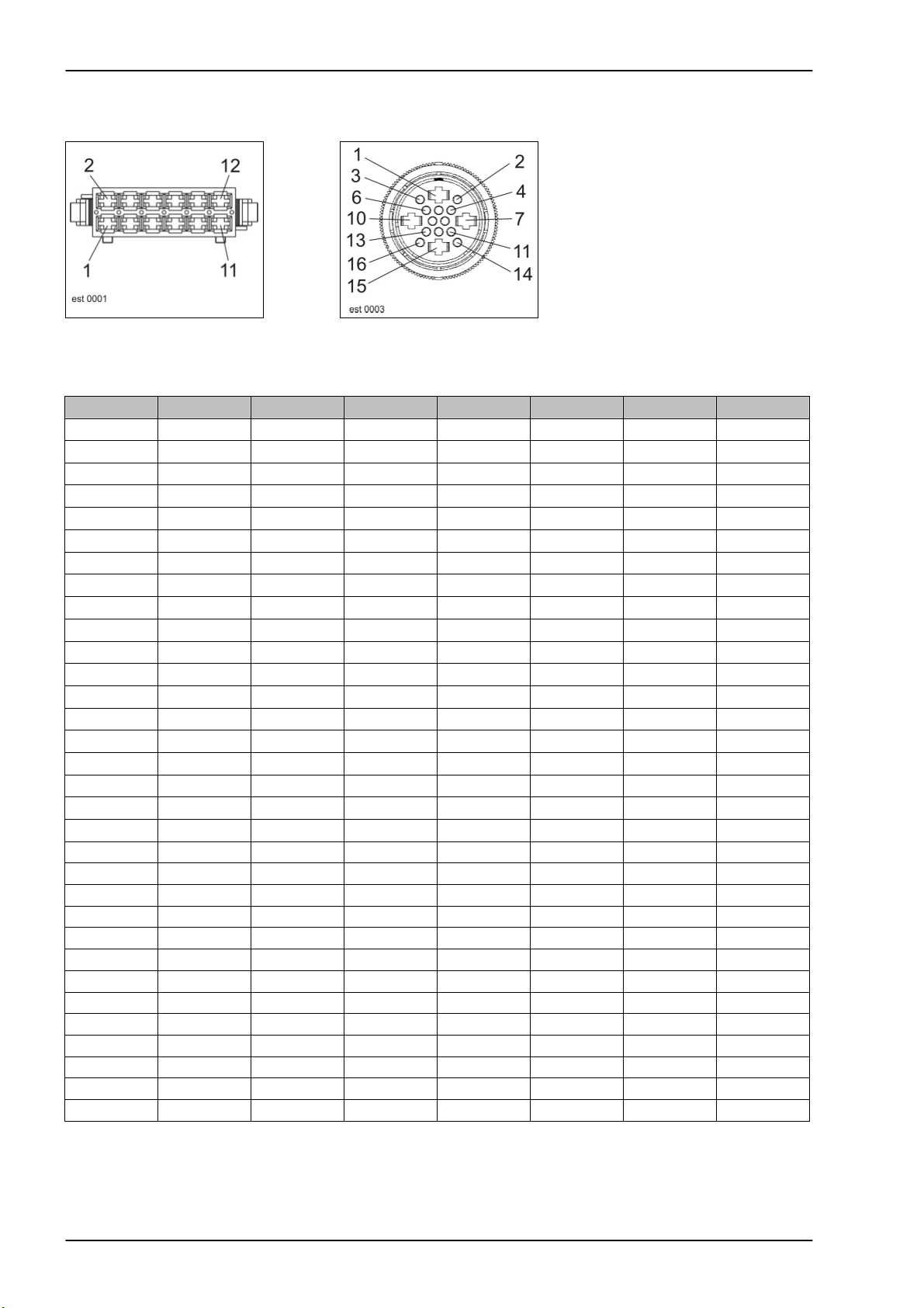
Connector pin definition:
Connector P, P1 Connector G Connector C
Interconnection list:
from to 1 to 2 to 3 to 4 to 5 mm² Colour
C-1 15 6 bk
C-2 G-7 C-21 1.5 bk-rd
C-3 K53-86 K56-86 K52-86 0.75 bk-ye
C-21 G-7 C-2 1.5 bk-rd
C-22 30 6 rd
G-1 K53-87 DS-43 4 bk-ye
G-7 C-2 C-21 1.5 bk-rd
G-16 C-18 K58-86 Cab-34 /
P-5 K13-30 1.5 vi-br
P-6 X-7 DI-7 1.5 vi-ye
P-12 31 2.5 br
P1-5 P-5 A36-8 1.5 vi-bl
0.75 bl
Bif-11
1s-4 Lex-e-01s 03/04
Page 23

02s
Starting the diesel engine,
Diesel engine speed adjustment
for Montana machines
Page 24
Electric System LEXION Montana TIC
02s - Starting the diesel engine, diesel engine speed adjustment - for Montana machines
Key to diagram:
Coordinates
A10 Fieldwork computer module (BIF/CAB) ............................. 2-h-20
A15 Electronic engine control module ...................................... 2-o-18
D1 Diesel engine error code LED............................................ 3-h-20
DC Caterpillar diagnosis .......................................................... 3-h-20
K51 Ignition switch relay ........................................................... 3-h-20
K56 Montana relay .................................................................... 3-h-20
R14 CAN bus matching resistor (J1939)................................... 3-h-20
S35 Engine speed adjustment switch ....................................... 3-g-17
U22 Diesel engine diagnosis switch.......................................... 3-h-20
Z33 Coolant level switch without engine cut-off system .......... 1-m-17
Measured value table:
Item Component Measured value Remark
K51 Remote control relay
70 A
115±10 Ω
(Pin 86/1 – 85/2)
(Pin 87/5 – 30/3)
2s-2 Lex-e-02s 03/04
Page 25

TIC LEXION Montana Electric System
Description of function:
Montana machine: In this circuit, the difference between the standard machine and the
Starting The safety start switch circuit of this engine is identical with the one used
Engine monitoring All sensors relevant for operation and monitoring of the engine are
Engine diagnosis The number of the engine errors occurred and the corresponding error
Diesel engine speed
adjustment
LEXION
Montana
Montana machine is only in a cable branch at connector Y to Y1. The
gearbox switch on connector Y is dropped for Montana machines.
The Montana functions are supplied with power via the unactuated relay
K56. During the starting process, relay K56 is actuated and thus interrupts
the power supply.
on the mechanically controlled engines.
The engine controller module (A15) is activated via relay K51 by the
ignition lock (S64). During the starting procedure, the engine controller
module (A15) receives the speed signal from the sensor provided on the
camshaft and starts the injection.
mounted on the engine wiring loom. Only the water level sensor is
connected to the CLAAS wiring loom.
The engine controller module (A15) transmits the signals for displaying
the engine speed and the coolant temperature to the CAB module (A10)
via the CAN bus J1939. The CAN module (A10) converts this signal to the
CLAAS CAN bus, thus allowing display on the terminal.
codes can be displayed in the terminal
(see also the error code list in the Electric System documentation
297550.x - Diagram 2e).
Further diagnosis is carried out via the diagnosis plug in the central
terminal compartment, using the Caterpillar diagnosis tool CAT-ET. The
display of error codes can also be activated by the diagnosis LED (D1)
after actuating the rocker switch (U22).
The diesel engine speed depends on the position of switch S35 and of the
2nd gear actual value switch (Z83) – see also circuit diagram 42s.
If full throttle speed is selected and the 2nd gear engaged (signal input
A36 / pin 4), the connection between Z41a and Z41b inside the Montana
gearshift control module (A36) is cut (pins 10 and 11) – see also circuit
diagram 42s.
The full throttle speed is reduced to road travel speed, depending on the
contry version. The maximum speed which can be achieved now can be
configured using the Claas diagnosis system CDS.
Type
470-420
Idle speed
(S35)
1200 rpm 2100 rpm 1568 rpm 1960 rpm
Full throttle at
no load
(S35)
20km/h
(Z83)
25km/h
(Z83)
03/04 Lex-e-02s 2s-3
Page 26
Electric System LEXION Montana TIC
Connector pin definition:
Connector MD, O, Y, Y1 Connector G
Interconnection list:
from to 1 to 2 to 3 to 4 to 5 mm² Colour
G-1 K53-87 DS-43 A15-64 M21-50 4 bk-ye
G-10 F34-A DS-4 A15-70 4 bk-rd
Y-3 W-7 DS-2 Cab-18 1.5 br-wh
Y-4 W-6 DS-1 O-10 Cab-19 1.5 br-ye
Y-9 K56-87a DS-3 1.5 bk
O-10 W-6 DS-1 Y-4 Cab-19 1.5 wh-rd
O-12 F19-A 2.5 bk
MD-1 30 A15-48 A15-52 A15-53 0.5 wh
MD-4 A15-8 XM-D 0.5 wh
MD-5 A15-9 XM-E 0.5 wh
MD-6 31 A15-61 A15-62 A15-63 XM-B
U22-1 0.5 wh
MD-7 A15-28 D2-K 0.5 wh
MD-8 A15-44 U22-2 0.5 wh
MD-9 A15-34 R14-B 0.5 wh
MD-10 A15-50 R14-A 0.5 wh
MD-11 A15-42 R14-C 0.5 wh
XM-A F59-A 0.5 wh
XM-B MD-6 U22-1 0.5 wh
XM-C MD-11 0.5 wh
XM-D MD-4 0.5 wh
XM-E MD-5 0.5 wh
XM-F MD-9 0.5 wh
XM-G MD-10 0.5 wh
Y1-3 Y-3 A36-10 1.5 br-gr
Y1-4 Y-4 A36-11 1.5 br-ye
Y1-9 Y-9 A50-RI-2+3 XSA-C4 XSA-B5 A36-2 1.5 bk
2s-4 Lex-e-02s 03/04
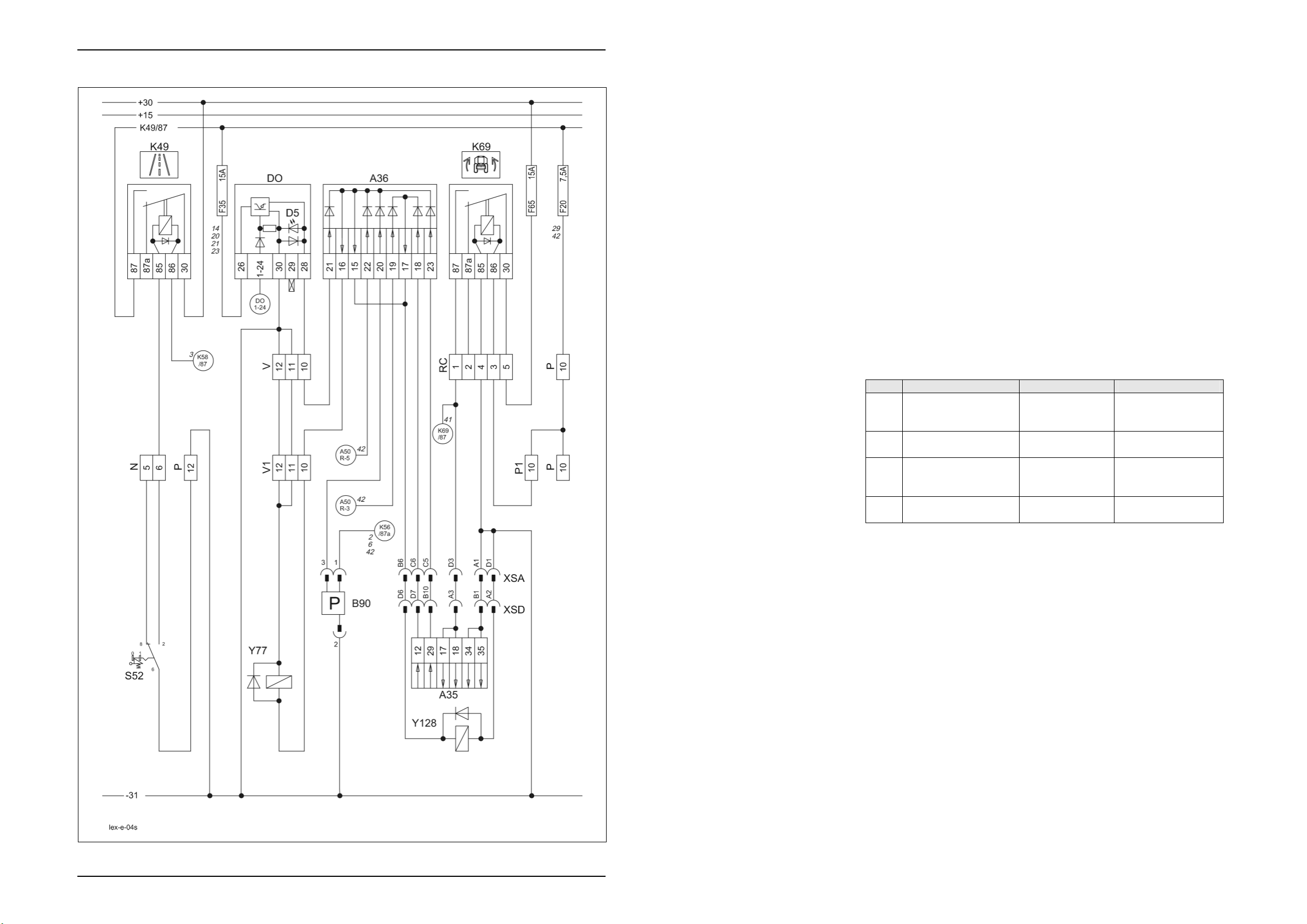
Page 27

4s
Road travel activation, master valve
for Montana machines (with RIO module A50)
Page 28
Electric System LEXION Montana TIC
04s - Road travel activation, working hydraulics master valve, for Montana machines with module A50 (RIO)
Key to diagram:
Coordinates
A35 Montana control unit module ...............................................7-i-18
A36 Montana gearshift control module ..................................... 2-h-20
B90 Brake accumulator pressure sensor/switch....................... 5-g-20
DO Master valve diode PCB .................................................... 3-h-20
D5 Master valve DO diode PCB LED...................................... 3-h-20
K49 Road travel main relay....................................................... 3-h-20
K69 Montana relay .................................................................... 3-h-20
S52 Road travel switch (red)..................................................... 3-g-17
Y77 Working hydraulics master valve solenoid coil ................. 6-m-21
Y128 Montana master valve solenoid coil .................................. 7-h-18
Measured value table:
Item Component Measured value Remark
B90 Brake circuit oil
pressure / charge
pressure
K49 Remote control relay
70 A
K69 Remote control relay
15 A
30 A
Y77
Y128
Solenoid coil 3.8 A
ON
OFF
115±10 Ω
95±10 Ω
3.2 Ω
< 135 bar
> 165 bar
(Pin 86/1 – 85/2)
(Pin 87/5 – 30/3)
(Pin 86/1 – 85/2)
(Pin 87a/4 – 30/3)
(Pin 87/5 – 30/3)
4s-2 Lex-e-04s 03/04
Page 29

TIC LEXION Montana Electric System
Description of function:
Montana machine: On Montana machines, actuation of the working hydraulics master valve
Activation of road travel During road travel, the road travel switch (S52) must be locked in order to
Working hydraulics master
valve
Montana axle hydraulics
master valve
Montana brake pressure
accumulator
Increased brake effect
Montana – only with module
A50 (RIO)
(Y77) is always via the gearshift control module (A36).
cut the power supply for all unnecessary electrical and hydraulic
functions.
In order to be able to build up the necessary working pressure for many
hydraulic controls, the neutral hydraulic circulation must be blocked (see
also the "Hydraulic system" section). In this case, the solenoid coil (Y77)
is actuated in parallel with the function directly via the diode PCB (DO)
and the gearshift control module (A36).
A LED (D5) provided on the diode PCB indicates the activation of the
circuit.
For the Montana functions as well, the circulation of the independent axle
control system hydraulics must be blocked (see also "Hydraulic System"
document).
According to the actuated functions, the Montana control unit (A35)
actuates the Montana master valve (Y128) and/or the working hydraulics
master valve (Y77) via the gearshift control module (A36).
The sensor/switch (B90) controls the brake system accumulator pressure
and, if necessary, actuates the working hydraulics master valve (Y77) via
the gearshift control module (A36) in order to recharge the brake circuit
accumulator.
If the diesel engine speed drops below 2300 rpm while braking, the RIO
module (A50) actuates the working hydraulics master valve (Y77) via
A50/pin R5 and the axle hydraulics master valve (Y128) via A50/pin R3.
This hydraulic load on the diesel engine increases the braking effect. In
addition, a brake restrictor is activated in the hydrostatic ground drive –
circuit diagram 42s.
03/04 Lex-e-04s 4s-3
Page 30
Electric System LEXION Montana TIC
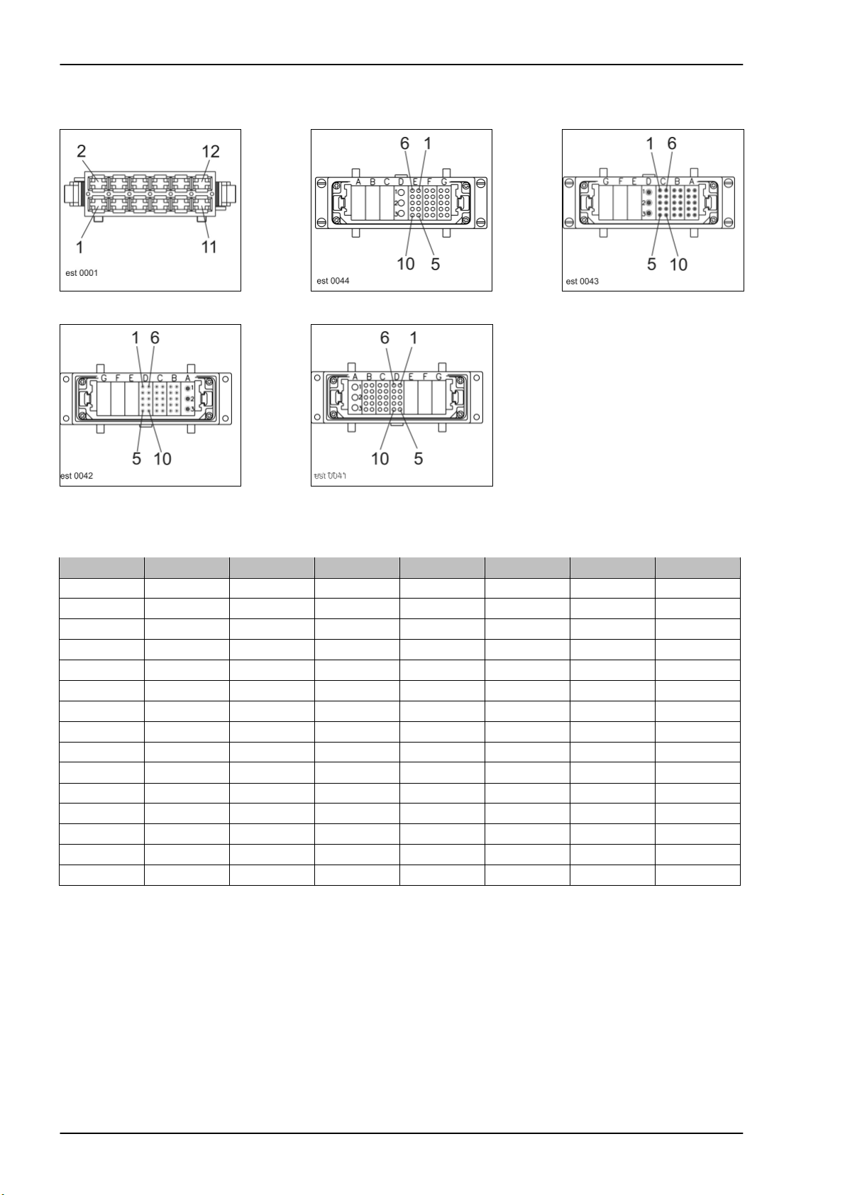
Connector pin definition:
Connector N, P, P1, V, V1 Connector XSA Connector XSA
Connector XSD Connector XSD
Interconnection list: I
from to 1 to 2 to 3 to 4 to 5 mm² Colour
N-5
N-6 K49-85 0.5 br-bl
P-10 F20-A 1.5 gn-rd
P-12 31 2.5 br
V-10 DO-28 A36-21 DS-50 1.5 pi-wh
V-11 31 2.5 br
V-12 31 2.5 br
P1-10 P-10 1.5 gn-rd
V1-10 A36-15+16 1.5 wh-pi
V1-11 V-11 2.5 br
V1-12 V-12 2.5 br
4s-4 Lex-e-04s 03/04
Page 31

TIC LEXION Montana Electric System
Interconnection list: II
from to 1 to 2 to 3 to 4 to 5 mm² Colour
XSA-A1 XSD-B1 1.5 br
XSA-B6 XSD-D6 1.5 gr-bl
XSA-C5 XSD-B10 1.5 rd-wh
XSA-C6 XSD-D7 1.5 gn-bk
XSA-D1 XSD-A2 4 br
XSA-D3 XSD-A3 4 rd-bk
XSD-A2 XSA-D1 1.5 br
XSD-A3 XSA-D3 1.5 gr-bl
XSD-B1 XSA-A1 1.5 rd-wh
XSD-B10 XSA-C5 1.5 gn-bk
XSD-D6 XSA-B6 4 br
XSD-D7 XSA-C6 4 rd-bk
03/04 Lex-e-04s 4s-5
Page 32

Electric System LEXION Montana TIC
4s-6 Lex-e-04s 03/04
Page 33

4t
Road travel activation, master valve
for Montana machines with module A45 (HBM)
Page 34

Electric System LEXION Montana TIC
04t - Road travel activation, working hydraulics master valve, for Montana machines with module A45 (HBM)
Key to diagram:
Coordinates
A35 Montana control unit module ...............................................7-i-18
A36 Montana gearshift control module ..................................... 2-h-20
B90 Brake accumulator pressure sensor/switch....................... 5-g-20
DO Master valve diode PCB .................................................... 3-h-20
D5 Master valve DO diode PCB LED...................................... 3-h-20
K49 Road travel main relay....................................................... 3-h-20
K69 Montana relay .................................................................... 3-h-20
S52 Road travel switch (red)..................................................... 3-g-17
Y77 Working hydraulics master valve solenoid coil ................. 6-m-21
Y128 Montana master valve solenoid coil .................................. 7-h-18
Measured value table:
Item Component Measured value Remark
B90 Brake circuit oil
pressure / charge
pressure
K49 Remote control relay
70 A
K69 Remote control relay
15 A
30 A
Y77
Y128
Solenoid coil 3.8 A
ON
OFF
115±10 Ω
95±10 Ω
3.2 Ω
< 135 bar
> 165 bar
(Pin 86/1 – 85/2)
(Pin 87/5 – 30/3)
(Pin 86/1 – 85/2)
(Pin 87a/4 – 30/3)
(Pin 87/5 – 30/3)
4t-2 Lex-e-04t 03/04
Page 35

TIC LEXION Montana Electric System
Description of function:
Montana machine: On Montana machines, actuation of the working hydraulics master valve
Activation of road travel During road travel, the road travel switch (S52) must be locked in order to
Working hydraulics master
valve
Montana axle hydraulics
master valve
Montana brake pressure
accumulator
Increased brake effect
Montana – only with module
A45 (HBM)
(Y77) is always via the gearshift control module (A36).
cut the power supply for all unnecessary electrical and hydraulic
functions.
In order to be able to build up the necessary working pressure for many
hydraulic controls, the neutral hydraulic circulation must be blocked (see
also the "Hydraulic system" section). In this case, the solenoid coil (Y77)
is actuated in parallel with the function directly via the diode PCB (DO)
and the gearshift control module (A36).
A LED (D5) provided on the diode PCB indicates the activation of the
circuit.
For the Montana functions as well, the circulation of the independent axle
control system hydraulics must be blocked (see also "Hydraulic System"
document).
According to the actuated functions, the Montana control unit (A35)
actuates the Montana master valve (Y128) and/or the working hydraulics
master valve (Y77) via the gearshift control module (A36).
The sensor/switch (B90) controls the brake system accumulator pressure
and, if necessary, actuates the working hydraulics master valve (Y77) via
the gearshift control module (A36) in order to recharge the brake circuit
accumulator.
If the diesel engine speed drops below 2300 rpm while braking, the HBM
module (A45) actuates the working hydraulics master valve (Y77) via
A36/pin 22 – Circuit diagram. This hydraulic load on the diesel engine
increases the braking effect.
In addition, a brake restrictor (Y124) is activated in the hydrostatic ground
drive – circuit diagram 42t.
03/04 Lex-e-04t 4t-3
Page 36

Electric System LEXION Montana TIC
Connector pin definition:
Connector N, P, P1, V, V1 Connector XSA Connector XSA
Connector XSD Connector XSD
Interconnection list: I
from to 1 to 2 to 3 to 4 to 5 mm² Colour
N-5
N-6 K49-85 0.5 br-bl
P-10 F20-A 1.5 gn-rd
P-12 31 2.5 br
V-10 DO-28 A36-21 DS-50 1.5 pi-wh
V-11 31 2.5 br
V-12 31 2.5 br
P1-10 P-10 1.5 gn-rd
V1-10 A36-15+16 1.5 wh-pi
V1-11 V-11 2.5 br
V1-12 V-12 2.5 br
4t-4 Lex-e-04t 03/04
Page 37

TIC LEXION Montana Electric System
Interconnection list: II
from to 1 to 2 to 3 to 4 to 5 mm² Colour
XSA-A1 XSD-B1 1.5 br
XSA-B6 XSD-D6 1.5 gr-bl
XSA-C5 XSD-B10 1.5 rd-wh
XSA-C6 XSD-D7 1.5 gn-bk
XSA-D1 XSD-A2 4 br
XSA-D3 XSD-A3 4 rd-bk
XSD-A2 XSA-D1 1.5 br
XSD-A3 XSA-D3 1.5 gr-bl
XSD-B1 XSA-A1 1.5 rd-wh
XSD-B10 XSA-C5 1.5 gn-bk
XSD-D6 XSA-B6 4 br
XSD-D7 XSA-C6 4 rd-bk
03/04 Lex-e-04t 4t-5
Page 38

Electric System LEXION TIC
4t-6 Lex-e-04t 03/04
Page 39

5s
Terminal, keyboard,
rotary switch, printer
for Montana machines with module A50 (RIO)
Page 40

Electric System LEXION Montana TIC
05s - Terminal, keyboard, rotary switch, printer, for Montana machines with module A50 (RIO)
Key to diagram:
Coordinates
A30 Terminal ............................................................................. 3-f-17
A35 Montana control unit module
A41 Montana terminal ................................................................ 3-f-17
T11 Function pre-selection ........................................................ 3-f-17
T19 Minus .................................................................................. 3-f-17
T26 Plus ..................................................................................... 3-f-17
XD CAN bus (7-pin) terminal .................................................... 4-f-17
X3 Printer ................................................................................. 4-f-17
XD2 Connector (data loading) .................................................... 4-f-17
5s-2 Lex-e-05s 03/04
Page 41

TIC LEXION Montana Electric System
r
Desc
iption of function:
Connectors The connectors L and ML are connected with the signal outputs to the
Power supply /
communication
Montana terminal (A41)
Connector XD2 Connector XD2 is used for loading the software of the Montana module
individual machine functions.
Connector A is connected with signal inputs from switches whose
actuated or non-actuated states allow the terminal to identify the machine
functions. The analog signals of the machine sensors are converted by
the corresponding modules (A10/A12) and read by the terminal as digital
signals from the CAN bus system.
The Montana terminal (A41) is supplied with power by the Montana
control unit module (A35) – see "Pin assignment in modules".
The Montana terminal (A41) performs all manual triggering of Montana
functions.
The Montana terminal (A41) communicates with the Montana control unit
module (A35) via an own CAN bus which is independent of the CLAAS
system.
(A35).
03/04 Lex-e-05s 5s-3
Page 42

Electric System LEXION Montana TIC
Connector pin definition:
Connector A Connector L Connector ML
Connector XD Connector XD2 Connector XSD
Connector XSD
Interconnection list:
from to 1 to 2 to 3 to 4 to 5 mm² Colour
ML-1 K35-86 0.5 rd-bl
ML-2 K36-86 0.5 rd-bk
ML-3 K54-86 0.5 br-wh
ML-4 K55-86 0.5 br-gr
ML-7 F-31A DS-56 1 bk-wh
ML-8 31 1 br
L-1 K29-86 0.5 ye-rd
L-2 K30-86 0.5 ye-br
L-3 K37-86 Cab-16 /
0.5 ye-bl
Bif-13
L-4 K38-86 Cab-2 /
0.5 ye-bk
Bif-12
L-5 K33-86 0.5 gr-wh
L-6 K34-86 0.5 gr-gn
L-7 K39-86 HAS-13 0.5 gr-rd
L-8 K40-86 HAS-25 0.5 gn-rd
L-9 K41-86 S-5 0.5 gn-br
L-10 K42-86 S-1 0.5 gn-bl
5s-4 Lex-e-05s 03/04
Page 43

TIC LEXION Montana Electric System
Interconnection list:
from to 1 to 2 to 3 to 4 to 5 mm² Colour
L-11 K43-86 S-7 0.5 gn-bk
L-12 K44-86 S-6 0.5 rd-wh
A-1 GY-1 0.5 wh
A-2 B-22 0.5 gn
A-3 B-21 0.5 ye
A-4 MN-4 DS-3 0.5 gr
A-5 B-20 W-11 DS-16 DA1-K K11-85
H-6 0.5 pi
A-6 G-2 K24-85 0.5 bl
A-7 B-19 0.5 rd
A-8 K11-87 DS-15 0.5 bk
A-9 MH-6 0.5 vi
A-10 MH-8 0.5 gr-pi
A-11 T-8 Y-2 0.5 rd-bl
A-12 G-6 DI-13 0.5 wh-gn
A-13 G-4 DI-12 0.5 br-gn
A-14 MH-5 K62-85 0.5 wh-ye
A-15 W-9 DI-4 0.5 ye-br
A-16 W-5 0.5 wh-gr
A-17 K23-87a G-13 0.5 gr-br
A-18 K57-49a C-20 0.5 gr
A-19 Cab-40 /
Bif-3
B-13 S-3 MV-3 MW-3 DS-62
E-31 MU-3 VGS-3 0.5 pi-br
A-20 Cab-13 /
Bif-16
B-14 S-9 MV-4 MW-4 DS-63
E-30 MU-4 VGS-16 0.5 wh-bl
A-21 F-32A 1 bk
A-22 31 1 br
A-23 F-51A DS-58 DS-59 1 rd
XSD - B5 0.5 wh-br
XSD - B6 0.5 pi
XSD - B7 0.5 wh-ye
XSD - B8 0.5 wh-rd
XSD - C1 0.5 wh-bl
XSD - C2 0.5 wh-gr
XSD - C3 0.5 wh-vi
XSD - C4 0.5 wh
DZW-3 MP-3 HAS-3 CAC-3
DZW-16 MP-4 HAS-16 CAC-16
03/04 Lex-e-05s 5s-5
Page 44

Electric System LEXION Montana TIC
5s-6 Lex-e-05s 03/04
Page 45

5t
Terminal, keyboard,
rotary switch, printer
for Montana machines with module A45 (HBM)
Page 46

Electric System LEXION Montana TIC
05t - Terminal, keyboard, rotary switch, printer, for Montana machines with module A45 (HBM)
Key to diagram:
Coordinates
A30 Terminal ............................................................................. 3-f-17
A35 Montana control unit module
A41 Montana terminal ................................................................ 3-f-17
T11 Function pre-selection ........................................................ 3-f-17
T19 Minus .................................................................................. 3-f-17
T26 Plus ..................................................................................... 3-f-17
XD CAN bus (7-pin) terminal .................................................... 4-f-17
X3 Printer ................................................................................. 4-f-17
XD2 Connector (data loading) .................................................... 4-f-17
5t-2 Lex-e-05t 03/04
Page 47

TIC LEXION Montana Electric System
r
Desc
iption of function:
Connectors The connectors L and ML are connected with the signal outputs to the
Power supply /
communication
Montana terminal (A41)
Connector XD2 Connector XD2 is used for loading the software of the Montana module
individual machine functions.
Connector A is connected with signal inputs from switches whose
actuated or non-actuated states allow the terminal to identify the machine
functions. The analog signals of the machine sensors are converted by
the corresponding modules (A10/A12) and read by the terminal as digital
signals from the CAN bus system.
The Montana terminal (A41) is supplied with power by the Montana
control unit module (A35) – see "Pin assignment in modules".
The Montana terminal (A41) performs all manual triggering of Montana
functions.
The Montana terminal (A41) communicates with the Montana control unit
module (A35) via an own CAN bus which is independent of the CLAAS
system.
(A35).
03/04 Lex-e-05t 5t-3
Page 48

Electric System LEXION Montana TIC
Connector pin definition:
Connector A Connector L Connector ML
Connector XD Connector XD2 Connector XSD
Connector XSD
Interconnection list:
from to 1 to 2 to 3 to 4 to 5 mm² Colour
ML-1 K35-86 0.5 rd-bl
ML-2 K36-86 0.5 rd-bk
ML-3 K54-86 0.5 br-wh
ML-4 K55-86 0.5 br-gr
ML-7 F-31A DS-56 1 bk-wh
ML-8 31 1 br
L-1 K29-86 0.5 ye-rd
L-2 K30-86 0.5 ye-br
L-3 K37-86 Cab-16 /
0.5 ye-bl
Bif-13
L-4 K38-86 Cab-2 /
0.5 ye-bk
Bif-12
L-5 K33-86 0.5 gr-wh
L-6 K34-86 0.5 gr-gn
L-7 K39-86 HAS-13 0.5 gr-rd
L-8 K40-86 HAS-25 0.5 gn-rd
L-9 K41-86 S-5 0.5 gn-br
L-10 K42-86 S-1 0.5 gn-bl
5t-4 Lex-e-05t 03/04
Page 49

TIC LEXION Montana Electric System
Interconnection list:
from to 1 to 2 to 3 to 4 to 5 mm² Colour
L-11 K43-86 S-7 0.5 gn-bk
L-12 K44-86 S-6 0.5 rd-wh
A-1 GY-1 0.5 wh
A-2 B-22 0.5 gn
A-3 B-21 0.5 ye
A-4 MN-4 DS-3 0.5 gr
A-5 B-20 W-11 DS-16 DA1-K K11-85
H-6 0.5 pi
A-6 G-2 K24-85 0.5 bl
A-7 B-19 0.5 rd
A-8 K11-87 DS-15 0.5 bk
A-9 MH-6 0.5 vi
A-10 MH-8 0.5 gr-pi
A-11 T-8 Y-2 0.5 rd-bl
A-12 G-6 DI-13 0.5 wh-gn
A-13 G-4 DI-12 0.5 br-gn
A-14 MH-5 K62-85 0.5 wh-ye
A-15 W-9 DI-4 0.5 ye-br
A-16 W-5 0.5 wh-gr
A-17 K23-87a G-13 0.5 gr-br
A-18 K57-49a C-20 0.5 gr
A-19 Cab-40 /
Bif-3
B-13 S-3 MV-3 MW-3 DS-62
E-31 MU-3 VGS-3 0.5 pi-br
A-20 Cab-13 /
Bif-16
B-14 S-9 MV-4 MW-4 DS-63
E-30 MU-4 VGS-16 0.5 wh-bl
A-21 F-32A 1 bk
A-22 31 1 br
A-23 F-51A DS-58 DS-59 1 rd
XSD - B5 0.5 wh-br
XSD - B6 0.5 pi
XSD - B7 0.5 wh-ye
XSD - B8 0.5 wh-rd
XSD - C1 0.5 wh-bl
XSD - C2 0.5 wh-gr
XSD - C3 0.5 wh-vi
XSD - C4 0.5 wh
DZW-3 MP-3 HAS-3 CAC-3
DZW-16 MP-4 HAS-16 CAC-16
03/04 Lex-e-05t 5t-5
Page 50

Electric System LEXION Montana TIC
5t-6 Lex-e-05t 03/04
Page 51

6s
CAN bus, module power supply
for Montana machines with module A50 (RIO)
Page 52

Electric System LEXION Montana TIC
06s - CAN bus, module power supply, for Montana machines with module A50 (RIO)
Key to diagram:
Coordinates
A1 AGROCOM terminal...........................................................2-h-17
A8 AUTOCONTOUR module (CAC) .......................................2-h-20
A9 AUTOPILOT module ..........................................................2-h-20
A10 Fieldwork computer module (BIF/CAB)..............................2-h-20
A12 Speed monitor module (DZW)............................................2-h-20
A13 Performance monitor module (DKG) ..................................4-p-21
A16 Reel controller module (HAS).............................................2-h-20
A21 YIELD METER module (LEM) ............................................2-h-20
A25 Sieve adjustment module ...................................................2-h-20
A27 VARIO module....................................................................2-h-20
A28 Uni-spreader module (VGS) ...............................................2-h-20
A40 Axle control system adaptation module..............................2-h-17
A50 Montana RIO module .........................................................2-h-20
B50 AUTOPILOT laser ..............................................................6-d-26
XA Multifunction coupling A......................................................8-e-21
XB Multifunction coupling B......................................................8-e-21
XC Multifunction coupling C .....................................................8-e-21
XV2 AUTOPILOT variant plug....................................................8-e-21
X5 Performance monitor ..........................................................6-p-20
6s-2 Lex-e-06s 03/04
Page 53

TIC LEXION Montana Electric System
Description of function:
Montana machine: On Montana machines, the Montana RIO module (A50) is connected with
the CAN bus by a cable branch line from connector MV to MV1.
Yield data All yield data is saved in the yield meter module (A21) whereas all other
performance data is saved in the fieldwork computer / CAN bridge module
(A10). It is therefore recommended to transmit these data prior to
replacing a defective module, using the diagnosis system
CDS3000/CDS5000.
Axle control system
adaptation
The CAN bus data of the separate Montana control unit are converted in
the axle control system adaptation module A40 and made available to the
CLAAS CAN bus system.
According to the axle position, the value of the feed rake conveyor
position sensor (B35) is offset in the AUTOCONTOUR module (CAC).
This allows working in hilly ground with the CAC function "Pre-set cutting
height control" and area counting.
AUTOCONTOUR (CAC)
Settings for Montana
The adaptation of the AUTOCONTOUR (CAC) and the axle control
systems requires special settings for Montana machines.
machines
- Cutterbar spring
setting
The 5 mm cutterbar spring setting (see also Operator's Manual) must be
made at a 50 % axle position.
- Check of cutterbar
spring setting
Check setting dimension when travelling downhill with the axle cylinders
fully extended. This dimension may be only < 15 mm.
- Learning the CAC limit
stops
The limit stops of the CAC sensors must be learned at a 75 % axle
position. While doing this, the cutting angle must be adjusted to the
working position
(cutterbar table surface in parallel with the ground).
- CAC sensitivity The recommended CAC sensitivity for use with the grain cutterbar is 45 %
with Montana machines.
- Drop rate setting
(front attachment)
The drop rate must be adjusted with the machine at operating
temperature and 50 % axle position.
The drop rate is 5 – 6 seconds from the top to the bottom position.
- Set value adjustment
of CAC cutting height
When working in the field, the cutting height control set value (working
within the sensor band range) should not be set higher than position 8.
control
03/04 Lex-e-06s 6s-3
Page 54

Electric System LEXION Montana TIC
Connector pin
assignment:
Connector S Connector
Socket XA Connector XA Socket XB
MV, MV1, MP, MR
Connector B, E
Connector XB Socket XC Connector XC
Connector X5 Connector XV2
6s-4 Lex-e-06s 03/04
Page 55

TIC LEXION Montana Electric System
Interconnection list:
from to 1 to 2 to 3 to 4 to 5 mm² Colour
S-2 31 0.5 br
S-3 Cab-40 /
Bif-3
B-13 CAC-3 MV-3 MW-3 DS-62
E-31 MU-3 VGS-3 MR-3 0.5 or
S-8 F-2A MV-1 MW-1 0.5 bk
S-9 Cab-13 /
Bif-16
B-14 CAC-16 MV-4 MW-4 DS-63
E-30 MU-4 VGS-16 MR-4 0.5 ye
MV-1 F2-A MW-1 S-8 0.5 bk
MV-2 31 1.5 br
MV-3 Cab-40 /
Bif-3
B-13 S-3 MW-3 MP-3 DS-62
E-31 MU-3 VGS-3 MR-3 0.5 or
MV-4 Cab-13 /
Bif-16
B-14 S-9 MW-4 MP-4 DS-63
E-30 MU-4 VGS-16 MR-4 0.5 ye
MV-5 F57-A 1.5 bk
MP-1 F9-A 0.5 bk
MP-2 31 1.5 br
MP-3 Cab-40 /
Bif-3
B-13 S-3 MV-3 MW-3 DS-62
E-31 MU-3 VGS-3 MR-3 0.5 or
MP-4 Cab-13 /
Bif-16
B-14 S-9 MV-4 MW-4 DS-63
E-30 MU-4 VGS-16 MR-4 0.5 ye
MR-1 F9-A 0.5 bk
MR-2 31 1.5 br
MR-3 Cab-40 /
Bif-3
B-13 S-3 MV-3 MW-3 DS-62
E-31 MU-3 VGS-3 MP-3 0.5 or
MR-4 Cab-13 /
Bif-16
B-14 S-9 MV-4 MW-4 DS-63
E-30 MU-4 VGS-16 MP-4 0.5 ye
DZW-3 MP-3 HAS-3 A-19
DZW-16 MP-4 HAS-16 A-20
DZW-3 CAC-3 HAS-3 A-19
DZW-16 CAC-16 HAS-16 A-20
DZW-3 CAC-3 HAS-3 A-19
DZW-16 CAC-16 HAS-16 A-20
DZW-3 CAC-3 HAS-3 A-19
DZW-16 CAC-16 HAS-16 A-20
03/04 Lex-e-06s 6s-5
Page 56

Electric System LEXION Montana TIC
Interconnection list:
from to 1 to 2 to 3 to 4 to 5 mm² Colour
B-13 Cab-40 /
Bif-3
MV-3 S-3 MW-3 MP-3 DS-62
E-31 MU-3 VGS-3 MR-3 0.5 or
B-14 Cab-13 /
Bif-16
MV-4 S-9 MW-4 MP-4 DS-63
E-30 MU-4 VGS-16 MR-4 0.5 ye
B-24 F3-A MU-1 1.5 bk
B-25 31 1.5 br-bl
E-1 31 1.5 br
E-12 31 1.5 br
E-21 F49-A 1.5 bl
E-30 Cab-13 /
Bif-16
MV-4 S-9 MW-4 MP-4 DS-63
B-14 MU-4 VGS-16 MR-4 0.5 ye
E-31 Cab-40 /
Bif-3
MV-3 S-3 MW-3 MP-3 DS-62
B-13 MU-3 VGS-3 MR-3 0.5 or
E-36 31 2.5 br
MV1-3 MV-3 A50-RI-4 0.5 or
MV1-4 MV-4 A50-RI-1 0.5 ye
DZW-3 CAC-3 HAS-3 A-19
DZW-16 CAC-16 HAS-16 A-20
DZW-16 CAC-16 HAS-16 A-20
DZW-3 CAC-3 HAS-3 A-19
6s-6 Lex-e-06s 03/04
Page 57

6t
CAN bus, module power supply
for Montana machines with module A45 (HBM)
Page 58

Electric System LEXION Montana TIC
06t - CAN bus, module power supply, for Montana machines with module A45 (HBM)
Key to diagram:
Coordinates
A1 AGROCOM terminal...........................................................2-h-17
A8 AUTOCONTOUR module (CAC) .......................................2-h-20
A9 AUTOPILOT module ..........................................................2-h-20
A10 Fieldwork computer module (BIF/CAB)..............................2-h-20
A12 Speed monitor module (DZW)............................................2-h-20
A13 Performance monitor module (DKG) ..................................4-p-21
A16 Reel controller module (HAS).............................................2-h-20
A21 YIELD METER module (LEM) ............................................2-h-20
A25 Sieve adjustment module ...................................................2-h-20
A27 VARIO module....................................................................2-h-20
A28 Uni-spreader module (VGS) ...............................................2-h-20
A40 Axle control system adaptation module..............................2-h-17
A45 Ground drive hydraulic motor brake
restrictor module (HBM) .....................................................2-h-20
B50 AUTOPILOT laser ..............................................................6-d-26
XA Multifunction coupling A......................................................8-e-21
XB Multifunction coupling B......................................................8-e-21
XC Multifunction coupling C .....................................................8-e-21
XV2 AUTOPILOT variant plug....................................................8-e-21
X5 Performance monitor ..........................................................6-p-20
6t-2 Lex-e-06t 03/04
Page 59

TIC LEXION Montana Electric System
Description of function:
Montana machine: On Montana machines, the Montana RIO module (A50) is connected with
the CAN bus by a cable branch line from connector MV to MV1.
Yield data All yield data is saved in the yield meter module (A21) whereas all other
performance data is saved in the fieldwork computer / CAN bridge
module (A10). It is therefore recommended to transmit these data prior to
replacing a defective module, using the diagnosis system
CDS3000/CDS5000.
Axle control system
adaptation
The CAN bus data of the separate Montana control unit are converted in
the axle control system adaptation module A40 and made available to the
CLAAS CAN bus system.
According to the axle position, the value of the feed rake conveyor
position sensor (B35) is offset in the AUTOCONTOUR module (CAC).
This allows working in hilly ground with the CAC function "Pre-set cutting
height control" and area counting.
AUTOCONTOUR (CAC)
Settings for Montana
The adaptation of the AUTOCONTOUR (CAC) and the axle control
systems requires special settings for Montana machines.
machines
- Cutterbar spring setting The 5 mm cutterbar spring setting (see also Operator's Manual) must be
made at a 50 % axle position.
- Check of cutterbar
spring setting
Check setting dimension when travelling downhill with the axle cylinders
fully extended. This dimension may be only < 15 mm.
- Learning the CAC limit
stops
The limit stops of the CAC sensors must be learned at a 75 % axle
position. While doing this, the cutting angle must be adjusted to the
working position
(cutterbar table surface in parallel with the ground).
- CAC sensitivity The recommended CAC sensitivity for use with the grain cutterbar is
45 % with Montana machines.
- Drop rate setting
(front attachment)
The drop rate must be adjusted with the machine at operating
temperature and 50 % axle position.
The drop rate is 5 – 6 seconds from the top to the bottom position.
- Set value adjustment of
CAC cutting height
When working in the field, the cutting height control set value (working
within the sensor band range) should not be set higher than position 8.
control
03/04 Lex-e-06t 6t-3
Page 60

Electric System LEXION Montana TIC
Connector pin
assignment:
Connector S Connector
Socket XA Connector XA Socket XB
MV, MV1, MP, MR
Connector B, E
Connector XB Socket XC Connector XC
Connector X5 Connector XV2
6t-4 Lex-e-06t 03/04
Page 61

TIC LEXION Montana Electric System
Interconnection list:
from to 1 to 2 to 3 to 4 to 5 mm² Colour
S-2 31 0.5 br
S-3 Cab-40 /
Bif-3
B-13 CAC-3 MV-3 MW-3 DS-62
E-31 MU-3 VGS-3 MR-3 0.5 or
S-8 F-2A MV-1 MW-1 0.5 bk
S-9 Cab-13 /
Bif-16
B-14 CAC-16 MV-4 MW-4 DS-63
E-30 MU-4 VGS-16 MR-4 0.5 ye
MV-1 F2-A MW-1 S-8 0.5 bk
MV-2 31 1.5 br
MV-3 Cab-40 /
Bif-3
B-13 S-3 MW-3 MP-3 DS-62
E-31 MU-3 VGS-3 MR-3 0.5 or
MV-4 Cab-13 /
Bif-16
B-14 S-9 MW-4 MP-4 DS-63
E-30 MU-4 VGS-16 MR-4 0.5 ye
MV-5 F57-A 1.5 bk
MP-1 F9-A 0.5 bk
MP-2 31 1.5 br
MP-3 Cab-40 /
Bif-3
B-13 S-3 MV-3 MW-3 DS-62
E-31 MU-3 VGS-3 MR-3 0.5 or
MP-4 Cab-13 /
Bif-16
B-14 S-9 MV-4 MW-4 DS-63
E-30 MU-4 VGS-16 MR-4 0.5 ye
MR-1 F9-A 0.5 bk
MR-2 31 1.5 br
MR-3 Cab-40 /
Bif-3
B-13 S-3 MV-3 MW-3 DS-62
E-31 MU-3 VGS-3 MP-3 0.5 or
MR-4 Cab-13 /
Bif-16
B-14 S-9 MV-4 MW-4 DS-63
E-30 MU-4 VGS-16 MP-4 0.5 ye
DZW-3 MP-3 HAS-3 A-19
DZW-16 MP-4 HAS-16 A-20
DZW-3 CAC-3 HAS-3 A-19
DZW-16 CAC-16 HAS-16 A-20
DZW-3 CAC-3 HAS-3 A-19
DZW-16 CAC-16 HAS-16 A-20
DZW-3 CAC-3 HAS-3 A-19
DZW-16 CAC-16 HAS-16 A-20
03/04 Lex-e-06t 6t-5
Page 62

Electric System LEXION Montana TIC
Interconnection list:
from to 1 to 2 to 3 to 4 to 5 mm² Colour
B-13 Cab-40 /
Bif-3
MV-3 S-3 MW-3 MP-3 DS-62
E-31 MU-3 VGS-3 MR-3 0.5 or
B-14 Cab-13 /
Bif-16
MV-4 S-9 MW-4 MP-4 DS-63
E-30 MU-4 VGS-16 MR-4 0.5 ye
B-24 F3-A MU-1 1.5 bk
B-25 31 1.5 br-bl
E-1 31 1.5 br
E-12 31 1.5 br
E-21 F49-A 1.5 bl
E-30 Cab-13 /
Bif-16
MV-4 S-9 MW-4 MP-4 DS-63
B-14 MU-4 VGS-16 MR-4 0.5 ye
E-31 Cab-40 /
Bif-3
MV-3 S-3 MW-3 MP-3 DS-62
B-13 MU-3 VGS-3 MR-3 0.5 or
E-36 31 2.5 br
MV1-3 MV-3 A50-RI-4 0.5 or
MV1-4 MV-4 A50-RI-1 0.5 ye
DZW-3 CAC-3 HAS-3 A-19
DZW-16 CAC-16 HAS-16 A-20
DZW-16 CAC-16 HAS-16 A-20
DZW-3 CAC-3 HAS-3 A-19
6t-6 Lex-e-06t 03/04
Page 63

17s
Front attachment drive,
reverser drive
for Montana machines
Page 64

Electric System LEXION Montana TIC
17s - Front attachment drive, reverser drive for Montana machines
Key to diagram:
Coordinates
A8 AUTOCONTOUR module (CAC)....................................... 2-h-20
A10 Fieldwork computer module (BIF/CAB) ............................. 2-h-20
A12 Speed monitor module (DZW) ........................................... 2-h-20
A16 Reel controller module (HAS) ............................................ 2-h-20
K16 Front attachment ON relay ............................................... 3-h-20
S54 Front attachment OFF switch ............................................ 3-g-17
S55 Front attachment ON switch .............................................. 3-g-17
S57 Front attachment reverse switch ..................................... 3-g-17
XEa Montana feed rake conveyor connector ............................ 5-g-17
XSA Montana operator's platform connector ............................. 5-h-17
XSD Montana operator's platform connector ............................. 5-h-17
X8 Ground speed control lever connector .............................. 4-h-17
Y86 Reverse front attachment solenoid coil ............................. 8-e-16
Y88 Front attachment clutch solenoid coil ................................ 2-p-19
Z5 Seat contact switch ............................................................ 4-g-18
Measured value table:
Item Component Measured value Remark
K16 Remote control relay
15 A
30 A
Y86 Solenoid coil 3.8 A
Y88 Solenoid coil 0.75 A
95±10 Ω
3.2 Ω
16 Ω
(Pin 86/1 – 85/2)
(Pin 87a/4 – 30/3)
(Pin 87/5 – 30/3)
17s-2 Lex-e-17s 03/04
Page 65

TIC LEXION Montana Electric System
Description of function:
Montana machine: In this circuit, the difference between the standard machine and the
Front attachment ON/OFF Relay K49 must be actuated by the road travel circuit and the threshing
Reverse front attachment The front attachment must not be engaged as a pre-condition for the
Montana machine is only two additional connectors (XSA and XSD) to
solenoid coil (Y86).
mechanism must be actuated by relay K14 as pre-conditions for the front
attachment drive.
When the START button (S55) is actuated, an earth signal is connected
to the fieldwork computer module (A10). The fieldwork computer module
(A10) now actuates relay K16. Solenoid coil (Y88) is supplied with
power – Front attachment ON function.
When the STOP button (S54) is actuated, an earth signal is connected to
the fieldwork computer module (A10). The fieldwork computer module
(A10) cuts the power supply at relay K16 – Front attachment OFF.
Important! The front attachment circuit depends on the closed seat
contact switch (Z5).
reversing function. The speed monitor module (A12) connects voltage to
the reverse switch (S57) as an additional safety feature only after the
feeder housing speed sensor (B12) stops transmitting a signal for approx.
2 seconds.
If these pre-conditions are met, voltage is connected from the speed
monitor module (A12) to solenoid coil (Y86) via the
reverse switch (S57) – Front attachment reverse function.
The master valve (Y77) is actuated via the diode PCB (DO) in parallel
with the solenoid coil (Y86) because this function requires that pressure is
built up in the system.
Important! When the reversing function is active, a signal is connected
to the reel controller module (A16) which makes the speed
adjustment variable displacement pump swing to maximum
delivery if hydraulic reel drive is used.
03/04 Lex-e-17s 17s-3
Page 66

Electric System LEXION Montana TIC
Connector pin definition:
Connector M, P, W Connector MQ Connector X8
Socket XEa Connector XEa Connector XSA
Connector XSD Connector XSD Connector XSA
17s-4 Lex-e-17s 03/04
Page 67

TIC LEXION Montana Electric System
Interconnection list:
from to 1 to 2 to 3 to 4 to 5 mm² Colour
M9 CAC-6 0.5 bl-gr
M10 CAC-18 0.5 wh-gn
W-2 K35-30 K16-87 K8-87 K15-30 CAC-7
K36-30 H-3 K64-86 DS-53 1 ye-rd
W-12 31 2.5 br
MQ-5 P-8 Do-2 DS-7 1.5 ye-bl
MQ-8 31 2.5 br
P-4 K47-TK R-1 0.5 bl-gn
P-7 K65-87a 1.5 gr
P-8 MQ-5 DO-2 DS-7 1.5 gr
P-12 31 2.5 br
XEa-1 XSD-A1 1.5 br
XEa-13 XSD-B4 1.5 ye-bl
XSA-A4 XSD-B4 1.5 ye-bl
XSA-D2 XSD-A1 4 br
XSD-A1 XEa-1 XSA-D2 4 br
XSD-B4 XEa-13 XSA-A4 1.5 ye-bl
03/04 Lex-e-17s 17s-5
Page 68

Electric System LEXION Montana TIC
17s-6 Lex-e-17s 03/04
Page 69

20s
Front attachment raise / lower,
cross levelling
for Montana machines
Page 70

Electric System LEXION Montana TIC
20s - Raise / lower front attachment, cross levelling – for Montana machines
Key to diagram:
Coordinates
A8 AUTOCONTOUR module (CAC)....................................... 2-h-20
K5 Front attachment raise relay .............................................. 3-h-20
K6 Front attachment lower relay ............................................. 3-h-20
K7 Left-hand cutterbar transverse control relay...................... 3-h-20
K8 Right-hand cutterbar transverse control relay ................... 3-h-20
S38a Front attachment raise multifunction pushbutton switch .... 3-f-18
S38b Front attachment lower multifunction pushbutton switch.... 3-f-18
S45 VARIO cutting table adjustment switch .............................. 3-f-18
S46 Cutterbar cross levelling switch (manual) .......................... 3-g-17
S69 Cross levelling /
table adjustment function pre-selection switch .................. 3-g-17
XEa Montana feed rake conveyor connector ............................ 5-g-17
XSA Montana operator's platform connector ............................. 5-h-17
XSD Montana operator's platform connector ............................. 5-h-17
X8 Ground speed control lever connector .............................. 4-h-17
Y67 Solenoid coil
AUTOCONTOUR cross levelling, left ................................. 7-f-16
Y68 Solenoid coil
AUTOCONTOUR cross levelling, right ............................... 7-f-16
Y85 Raise front attachment solenoid coil................................. 6-m-21
Y87 Lower front attachment solenoid coil ................................ 6-m-21
Measured value table:
Item Component Measured value Remark
K 5
K 6
K 7
K 8
Y67
Y68
Y85
Y87
Remote control relay
30 A
Solenoid coil 3.8 A
200±20 Ω
3.2 Ω
(Pin 86/1 - 85/2)
(Pin 87/5 – 30/3)
20s-2 Lex-e-20s 03/04
Page 71

TIC LEXION Montana Electric System
Description of function:
Montana machine: In this circuit, the difference between the standard machine and the
Raise / lower front
attachment
The pushbuttons (S38a and S38b) have different pressure stages. When
When pressing the pushbuttons (S38a or S38b) to the second stage, the
The master valve (Y77) is actuated via the diode PCB (DO) in parallel
During automatic cutterbar guiding, the AUTOCONTOUR module (A8)
Cross levelling When the road travel circuit is unlocked, relays K7 and K8 are supplied
By actuating the function pre-selection switch (S69) to the cross levelling
The master valve (Y77) is actuated via the diode PCB (DO) in parallel
During automatic cutterbar guiding, the AUTOCONTOUR module (A8)
Montana machine is only two additional connectors (XSA and XSD) to the
solenoid coils (Y67 and Y68).
When the road travel circuit is unlocked, relays K5 and K6 are supplied
with power by relay K49.
actuating the pushbutton slightly to the first stage, earth is connected as a
signal to the AUTOCONTOUR module (A8). The module (A8) actuates
the respective solenoid coils (Y85 or Y86) in a modulated way – Slowly
raise/lower function.
corresponding relays K5 and K6 are actuated and consequently also the
respective solenoid coils (Y85 or Y86) – Quickly raise/lower function.
with the front attachment raise solenoid coil (Y85) because this function
requires that pressure is built up in the system.
actuates the corresponding solenoid coils until the set values and actual
values of the corresponding sensors match.
with power by relay K49.
position, the respective relay K5 or K6 and consequently the
corresponding solenoid coil (Y67/Y68) is actuated as a function of switch
(S46).
with the cross levelling solenoid coils (Y67/Y68) because this function
requires that pressure is built up in the system.
actuates the corresponding solenoid coils until the set values and actual
values of the corresponding sensors match.
Important! The switch provided at the bottom side of the multi-function
handle controls both the VARIO cutting table adjustment
(S45) and the manual cutterbar lateral control (S46),
depending on the function pre-selection switch (S69).
03/04 Lex-e-20s 20s-3
Page 72

Electric System LEXION Montana TIC
Connector pin definition:
Connector M, MA, N, P, V Connector MQ Connector X8
Socket XEa Connector XEa Connector XSA
Connector XSD Connector XSD Connector XSA
20s-4 Lex-e-20s 03/04
Page 73

TIC LEXION Montana Electric System
Interconnection list:
from to 1 to 2 to 3 to 4 to 5 mm² Colour
MQ-3 K8-87 CAC-1 1.5 ye-vi
MQ-4 K7-87 CAC-14 1.5 ye-br
MQ-8 31 2.5 br
N-7 K7-85 1.5 gn-wh
N-8 K8-85 1.5 gn-ye
MA-6 K9-85 0.5 gr-gn
MA-7 K10-85 0.5 gr-br
V-5 K5-87 CAC-13 Do-8 DS-5 1.5 wh-rd
V-6 K6-87 CAC-12 DS-6 1.5 wh-bk
V-11 31 2.5 br
V-12 31 2.5 br
M-1 CAC-19 0.5 gr-wh
M-2 K6-85 0.5 gr-ye
M-3 CAC-5 0.5 gr-br
M-4 K5-85 0.5 gr-gn
P-12 31 2.5 br
XEa-1 XSD-A1 1.5 br
XEa-11 XSD-B2 1.5 vi-ye
XEa-12 XSD-B3 1.5 ye-br
XSA-A2 XSD-B2 1.5 vi-ye
XSA-A3 XSD-B3 1.5 ye-br
XSA-D2 XSD-A1 4 br
XSD-A1 XEa-1 XSA-D2 4 br
XSD-B2 XEa-11 XSA-A2 1.5 vi-ye
XSD-B3 XEa-12 XSA-A3 1.5 ye-br
03/04 Lex-e-20s 20s-5
Page 74

Electric System LEXION Montana TIC
20s-6 Lex-e-20s 03/04
Page 75

26s
Machine monitor
for Montana machines
Page 76

Electric System LEXION Montana TIC
26s - Machine monitoring, for Montana machines
Key to diagram:
Coordinates
DI Warning device diode PCB................................................ 3-h-20
X13 3D / rear axle connector .................................................... 3-g-17
Z1 3D sieve pan position switch ............................................. 6-o-16
Z19 Hydraulic oil level switch (min.).......................................... 2-p-20
Z20 Hydraulic oil temperature switch ........................................ 2-p-20
Z38 Steering position left switch ............................................... 7-q-16
Z39 Steering position right switch ............................................. 7-q-16
Z46 Low-pressure hydraulics switch /
ground drive oil pressure ................................................... 2-p-19
Z61 Straw blockage warning switch .......................................... 2-t-18
............................................................................................ 4-t-20
Z79 Left brake circuit pressure switch ...................................... 5-g-20
Z80 Right brake circuit pressure switch ................................... 5-g-20
26s-2 Lex-e-26s 03/04
Page 77

TIC LEXION Montana Electric System
Description of function:
Montana machine In this circuit, the difference between the standard machine and the
Filling level warning If the diesel engine is not started, the terminal (A30) recognizes an earth
Oil pressure warning If the diesel engine is started, the terminal (A30) recognizes an earth
Warning: Hydraulic oil
temperature too high
Montana brake oil pressure
warning
Montana machine is a cable branch at connector Y to Y1. The parking
brake switch at the connectors T and U is dropped on Montana machines.
In addition to the warning signals for brake lining wear (Z9) and parking
brake (Z12), insufficient brake oil pressure (Z80) is also displayed in the
terminal.
signal on pin 15 as the signal of the float switch (Z19) and displays the
filling level alarm message. At the same time, the earth signal is sent to
the pulse generator K57 through the diode PCB (DI).
signal on pin 15 as the signal of the oil pressure switch (Z46) and displays
the oil pressure alarm message. At the same time, the earth signal is sent
to the pulse generator K57 through the diode PCB (353).
The earth signal of the hydraulic oil temperature switch (Z20) is connected
to terminal (A30) and displayed as an alarm message.
The earth signal of the left / right brake circuit pressure switch (Z79/Z80)
is connected to the terminal (A30) and displayed as an alarm message.
03/04 Lex-e-26s 26s-3
Page 78

Electric System LEXION Montana TIC
Connector pin definition:
Connector T, U, W, Y, Y1 Connector MW Connector B
Interconnection list:
from to 1 to 2 to 3 to 4 to 5 mm² Colour
T-8 A-11 Y-2 1.5 br-wh
U-4 31 2.5 br
Y-1 31 2.5 br
Y-2 T-8 A-11 0.75 br-rd
W-5 A-16 0.75 br-wh
W-9 A-15 DI-4 1 gn-rd
W-12 31 2.5 br
B-19 A-7 1 bk-gr
B-21 A-3 1 bl-gr
B-22 A-2 1 bl-vi
B-37 31 1.5 br
MW-1 F2-A MV-1 S-8 0.5 bk
MW-2 31 1.5 br
MW-7 DI-10 0.5 wh
Y1-2 Y-2 1.5 br-rd
26s-4 Lex-e-26s 03/04
Page 79

41s
Axle control system,
front attachment control system
for Montana machines with module A50 (RIO)
Page 80

Electric System LEXION-Montana TIC
41s - Axle control system and front attachment control system, for Montana machines with module A50 (RIO)
Key to diagram:
Coordinates
A35 Montana control unit module ...............................................7-i-18
B91 Axle angle sensor, left ........................................................ 7-j-20
B92 Axle angle sensor, right ...................................................... 7-j-16
B93 Cutting angle sensor.......................................................... 7-e-17
B94 Montana cross levelling sensor ......................................... 8-e-16
B95 Montana feed rake conveyor position sensor.................... 6-h-16
XEa Montana feed rake conveyor connector ............................ 5-g-17
XSA Montana operator's platform .............................................. 5-h-17
XSD Montana operator's platform.............................................. 5-h-17
Y110 Raise cutting angle solenoid coil ........................................ 7-f-16
Y111 Lower cutting angle solenoid coil........................................ 7-f-16
Y112 Rotate front attachment to the right solenoid coil ............... 7-f-16
Y113 Rotate front attachment to the left solenoid coil ................. 7-f-16
Y114 Lower axle on left-hand side solenoid coil......................... 7-h-18
Y115 Raise axle on left-hand side solenoid coil ......................... 7-h-18
Y116 Lower axle on right-hand side solenoid coil....................... 7-h-18
Y117 Raise axle on right-hand side solenoid coil ....................... 7-h-18
Y118 Oil quantity increase solenoid coil ..................................... 7-h-18
Measured value table:
Item Component Measured value Remark
B91
B92
B93
B94
Y110
Y111
Y112
Y113
Y114
Y115
Y116
Y117
Y118
Sensor 12 V
0.25 V – 4.75 V
Solenoid coil 3.8 A
3.2 Ω
(Pin 1-2)
(Pin 1-3)
41s-2 Lex-e-41s 03/04
Page 81

TIC LEXION-Montana Electric System
Description of function:
1/5
Axle control system and
front attachment control
system
The system identifies the machine position using an inclination sensor
integrated in the Montana module (A35). The solenoid coils (Y114, Y115,
Y116, Y117) are actuated by the Montana module (A35) so that the
machine is always in a vertical position by means of front axle
movements. If the control system speed is not sufficient, the Montana
module (A35) additionally actuates an oil quantity increase solenoid coil
(Y118) in connection with the working hydraulics master valve (Y77) via
the gearshift control module (A36) – circuit diagram 4.
The position of the front attachment is adapted by rotating the front
attachment frame (Y112, Y113) and by changing the cutting angle (Y110,
Y111). This front attachment control system works independently of the
AUTOCONTOUR system.
The Montana module (A35) receives the necessary feedback about the
current position of the corresponding function from the respective angle
sensors (B91, B92, B93, B94, B95).
Important! All system calibrations using the Montana terminal (A41)
require that the Montana control unit module A35 receives
the signal from the unactuated parking brake (S93) – circuit
diagram 42.
Axle control system
diagnosis via Montana
Call up the diagnosis menu with the menu key, the yellow cutting angle
increase / decrease keys and the Enter key.
terminal A41:
- Diagnosis inputs Select the inputs section using the yellow keys and the Enter key.
Diagnose
Inputs
Inclinometer
Outputs
System
03/04 Lex-e-41s 41s-3
Page 82

Electric System LEXION-Montana TIC
Description of function:
2/5
Go to page 1/6 inputs using the yellow keys and the Enter key.
The parking brake symbol allows checking the function of parking brake
switch S93 (symbol) – closed / open.
Diag. Inputs 1/6
Handbrake
Reserve 1
Reserve 2
Go to page 2/6 inputs using the yellow keys and the Enter key.
The sensor value B91 is displayed.
Diag. Inputs 2/6
Cylinder left
Sensor:
Cal.min.:
Cal.max.:
Position:
3.30 V
0.12 V
4.99 V
65.3%
Go to page 3/6 inputs using the yellow keys and the Enter key.
The sensor value B92 is displayed.
Diag. Inputs 3/6
Cylinder right
Sensor:
Cal.min.:
Cal.max.:
Position:
2.01 V
0.00 V
4.86 V
41.3%
Go to page 4/6 inputs using the yellow keys and the Enter key.
The sensor value B93 is displayed.
Diag. Inputs 4/6
Cutting angle
Sensor:
Cal.min.:
Cal.max.:
Position:
3.47 V
2.64 V
3.80 V
71.8%
41s-4 Lex-e-41s 03/04
Page 83

TIC LEXION-Montana Electric System
Description of function:
The sensor value B94 is displayed.
Go to page 6/6 inputs using the yellow keys and the Enter key.
The sensor value B95 is displayed.
3/5
Go to page 5/6 inputs using the yellow keys and the Enter key.
Diag. Inputs 5/6
Cross inclinat.
Sensor:
Cal.min.:
Cal.max.:
Position:
Note: Sensor B95 is not used by the system.
Diag. Inputs 6/6
Feeder housing
Sensor:
Cal.min.:
Cal.max.:
Position:
1.57 V
1.18 V
2.53 V
28.7%
2.78 V
0.00 V
4.86 V
57.2%
03/04 Lex-e-41s 41s-5
Page 84

Electric System LEXION-Montana TIC
Description of function:
- Inclinometer diagnosis Press menu key.
Select the inclinometer section using the yellow keys and the Enter key.
Go to page 1/1 Inclinometer using the yellow keys and the Enter key.
The inclinometer is integrated in module A35.
The most recently calibrated values cal. X / cal. Y can be compared with
- Diagnosis outputs Press menu key.
The outputs section cannot be used for axle control system diagnosis
4/5
Diagnose
Inputs
Inclinometer
Outputs
System
the current actual values of angle X and angle Y.
Diag. Inclino.
Angle X: 52 inc.
Cal. X: 155 inc.
Angle Y: 71 inc.
Cal. Y: 201 inc.
since the diagnosis mode does not allow axle control system operating
functions.
Diagnose
Inputs
Inclinometer
Outputs
System
1/1
41s-6 Lex-e-41s 03/04
Page 85

TIC LEXION-Montana Electric System
Description of function:
- Power supply diagnosis Press menu back key. Select the system section using the yellow keys
Go to page 1/1 system using the yellow keys and the Enter key. The
The power supply 1 value is not used by the system.
5/5
and the Enter key.
Diagnose
Inputs
Inclinometer
Outputs
System
power supply 2 value displays the current supply voltage of module A35.
Diag. System 1/1
Supply 1:
Supply 2:
4.89 V
12.5 V
03/04 Lex-e-41s 41s-7
Page 86

Electric System LEXION-Montana TIC
Connector pin definition:
Socket XEa Connector XEa Connector XSA
Connector XSD Connector XSD Connector XSA
Interconnection list:
from to 1 to 2 to 3 to 4 to 5 mm² Colour
XEa-1 XSD-A1 1.5 br
XEa-2 0.75 br-rd
XEa-3 0.75 vi-bl
XEa-4 0.75 gn-vi
XEa-5 0.75 br-bl
XEa-6 0.75 bl-bk
XEa-7 1.5 gr-vi
XEa-8 1.5 gr-ye
XEa-9 1.5 bl-gr
XEa-10 1.5 gr-wh
XSA-A1 XSD-B1 1.5 br
XSA-A2 XSD-B2 1.5 vi-ye
XSA-D2 XSD-A1 4 br
XSA-D3 XSD-A3 4 rd-bk
XSD-A1 XEa-1 XSA-D2 4 br
XSD-A3 XSA-D3 4 rd-bk
XSD-B1 XSA-A1 1.5 bk-rd
XSD-B5 1.5 wh-br
XSD-B6 1.5 wh-pi
XSD-B7 1.5 wh-ye
XSD-B8 1.5 wh-rd
XSD-D1 XSA-B1 1.5 gr-bk
41s-8 Lex-e-41s 03/04
Page 87

41t
Axle control system,
front attachment control system
for Montana machines with module A45 (HBM)
Page 88

Electric System LEXION Montana TIC
41t - Axle control system and front attachment control system,
for Montana machines with module A45 (HBM)
Key to diagram:
Coordinates
A35 Montana control unit module ...............................................7-i-18
B91 Axle angle sensor, left ........................................................ 7-j-20
B92 Axle angle sensor, right ...................................................... 7-j-16
B93 Cutting angle sensor.......................................................... 7-e-17
B94 Montana cross levelling sensor ......................................... 8-e-16
B95 Montana feed rake conveyor position sensor.................... 6-h-16
B126-1 Axle control system inclination sensor 1
B126-2 Axle control system inclination sensor 2
XEa Montana feed rake conveyor connector ............................ 5-g-17
XSA Montana operator's platform .............................................. 5-h-17
XSD Montana operator's platform.............................................. 5-h-17
Y110 Raise cutting angle solenoid coil ........................................ 7-f-16
Y111 Lower cutting angle solenoid coil........................................ 7-f-16
Y112 Rotate front attachment to the right solenoid coil ............... 7-f-16
Y113 Rotate front attachment to the left solenoid coil ................. 7-f-16
Y114 Lower axle on left-hand side solenoid coil......................... 7-h-18
Y115 Raise axle on right-hand side solenoid coil ....................... 7-h-18
Y116 Lower axle on right-hand side solenoid coil....................... 7-h-18
Y117 Raise axle on right-hand side solenoid coil ....................... 7-h-18
Y118 Oil quantity increase solenoid coil ..................................... 7-h-18
Measured value table:
Item Component Measured value Remark
B91
B92
B93
B94
B95
Y110
Y111
Y112
Y113
Y114
Y115
Y116
Y117
Y118
Sensor 12 V
0.25 V – 4.75 V
Solenoid coil 3.8 A
Ω
3.2
(Pin 1-2)
(Pin 1-3)
41t-2 Lex-e-41t 03/04
Page 89

TIC LEXION Montana Electric System
Description of function:
Axle control system and
front attachment control
system
Axle control system
diagnosis via Montana
terminal A41
- Diagnosis inputs Select the inputs section using the yellow keys and the Enter key.
1/5
The system identifies the machine position using the inclination sensors
B126-1 / B126-2 which transmit their values to the Montana module (A35)
via an internal CAN bus. The solenoid coils (Y114, Y115, Y116, Y117) are
actuated by the Montana module (A35) so that the machine is always in a
vertical position by means of front axle movements. If the control system
speed is not sufficient, the Montana module (A35) additionally actuates an
oil quantity increase solenoid coil (Y118) in connection with the working
hydraulics master valve (Y77) via the gearshift control module (A36) –
circuit diagram 4.
The position of the front attachment is adapted by rotating the front
attachment frame (Y112, Y113) and by changing the cutting angle (Y110,
Y111). This front attachment control system works independently of the
AUTOCONTOUR system.
The Montana module (A35) receives the necessary feedback about the
current position of the corresponding function from the respective angle
sensors (B91, B92, B93, B94, B95).
Important! All system calibrations using the Montana terminal (A41)
require that the Montana control unit module A35 receives
the signal from the unactuated parking brake (S93) – circuit
diagram 42.
Call up the diagnosis menu with the menu key, the yellow cutting angle
increase / decrease keys and the Enter key.
Diag. Inclino. 2/2
Angle X:
Cal. X:
Angle Y:
Cal. Y:
0.9 Deg
-1.6 Deg
1.1 Deg
-2.9 Deg
03/04 Lex-e-41t 41t-3
Page 90

Electric System LEXION Montana TIC
Description of function:
Go to page 1/6 inputs using the yellow keys and the Enter key.
The parking brake symbol allows checking the function of parking brake
Go to page 2/6 inputs using the yellow keys and the Enter key.
The sensor value B91 is displayed.
2/5
switch S93 (symbol) – closed / open.
Diagnose
Inputs
Inclinometer
Outputs
System
Diagnose
Inputs
Inclinometer
Outputs
System
Go to page 3/6 inputs using the yellow keys and the Enter key.
The sensor value B92 is displayed.
Diag. System 1/1
Supply 1:
Supply 2:
Go to page 4/6 inputs using the yellow keys and the Enter key.
The sensor value B93 is displayed.
4.89 V
12.5 V
Diag. Inputs 4/6
Cutting angle
Sensor:
Cal.min.:
Cal.max.:
Position:
3.47 V
2.64 V
3.80 V
71.8%
41t-4 Lex-e-41t 03/04
Page 91

TIC LEXION Montana Electric System
Description of function:
The sensor value B94 is displayed.
Go to page 6/6 inputs using the yellow keys and the Enter key.
The sensor value B95 is displayed.
Note: Sensor B95 is not used by the system.
3/5
Go to page 5/6 inputs using the yellow keys and the Enter key.
Diag. Inputs 5/6
Cross inclinat.
Sensor:
Cal.min.:
Cal.max.:
Position:
Diag. Input 6/6
Feeder housing
Sensor:
Cal.min.:
Cal.max.:
Position:
1.57 V
1.18 V
2.53 V
28.7%
2.78 V
0.00 V
4.86 V
57.2%
03/04 Lex-e-41t 41t-5
Page 92

Electric System LEXION Montana TIC
Description of function:
- Inclinometer diagnosis Press menu key.
Select the inclinometer section using the yellow keys and the Enter key.
Go to page 1/2 Inclinometer using the yellow keys and the Enter key.
The most recently calibrated values cal. X / cal. Y can be compared with
4/5
Diagnose
Inputs
Inclinometer
Outputs
System
The values of sensor B126-1 are displayed.
the current actual values of angle X and angle Y.
The sensor value B126-1 can be compared with sensor B126-2
- page 2/2.
Diag. Inclino. 1/2
Angle X:
Cal. X:
Angle Y:
Cal. Y:
0.9 Deg
-1.6 Deg
1.1 Deg
-2.9 Deg
Go to page 2/2 Inclinometer using the yellow keys and the Enter key.
The values of sensor B126-2 are displayed.
The most recently calibrated values cal. X / cal. Y can be compared with
the current actual values of angle X and angle Y.
The sensor value B126-2 can be compared with sensor B126-1
- page 1/2.
Diag. Inclino. 2/2
Angle X:
Cal. X:
Angle Y:
Cal. Y:
0.9 Deg
-1.6 Deg
1.1 Deg
-2.9 Deg
41t-6 Lex-e-41t 03/04
Page 93

TIC LEXION Montana Electric System
Description of function:
- Output diagnosis Press menu key.
The outputs section cannot be used for axle control system diagnosis
- Power supply diagnosis Press menu back key. Select the system section using the yellow keys
5/5
since the diagnosis mode does not allow axle control system operating
functions.
Diagnose
Inputs
Inclinometer
Outputs
System
and the Enter key.
Diagnose
Inputs
Inclinometer
Outputs
System
Go to page 1/1 system using the yellow keys and the Enter key. The
power supply 2 value displays the current supply voltage of module A35.
The power supply 1 value is not used by the system.
Diag. System 1/1
Supply 1:
Supply 2:
4.89 V
12.5 V
03/04 Lex-e-41t 41t-7
Page 94

Electric System LEXION Montana TIC
Connector pin definition:
Socket A35
Socket XEa Connector XEa Connector XSA
Connector XSD Connector XSD Connector XSA
41t-8 Lex-e-41t 03/04
Page 95

TIC LEXION Montana Electric System
Interconnection list:
from to 1 to 2 to 3 to 4 to 5 mm² Colour
XEa-1 XSD-A1 1.5 br
XEa-2 0.75 br-rd
XEa-3 0.75 vi-bl
XEa-4 0.75 gn-vi
XEa-5 0.75 br-bl
XEa-6 0.75 bl-bk
XEa-7 1.5 gr-vi
XEa-8 1.5 gr-ye
XEa-9 1.5 bl-gr
XEa-10 1.5 gr-wh
XSA-A1 XSD-B1 1.5 br
XSA-A2 XSD-B2 1.5 vi-ye
XSA-D2 XSD-A1 4 br
XSA-D3 XSD-A3 4 rd-bk
XSD-A1 XEa-1 XSA-D2 4 br
XSD-A3 XSA-D3 4 rd-bk
XSD-B1 XSA-A1 1.5 bk-rd
XSD-B5 1.5 wh-br
XSD-B6 1.5 wh-pi
XSD-B7 1.5 wh-ye
XSD-B8 1.5 wh-rd
XSD-D1 XSA-B1 1.5 gr-bk
03/04 Lex-e-41t 41t-9
Page 96

Electric System LEXION TIC
41t-10 Lex-e-41t 03/04
Page 97

42s
Ground drive and brake control
for Montana machines with module A50 (RIO)
Page 98

Electric System LEXION Montana TIC
42s - Ground drive and brake control, for Montana machines with module A50 (RIO)
Key to diagram:
Coordinates
A36 Montana gearshift control module ..................................... 2-h-20
A50 Montana RIO module......................................................... 2-h-20
E35 Instrument lighting ............................................................. 3-g-17
H60 1
H61 2
st
gear signal light ............................................................. 3-g-17
nd
gear signal light ............................................................ 3-g-17
S90 Gearshift control switch ..................................................... 3-g-17
S91 Shifting aid switch .............................................................. 3-g-17
S92 Hydraulic motor fast/slow switch ....................................... 3-g-17
S93 Parking brake switch.......................................................... 3-g-17
S94 Differential lock switch ........................................................ 5-f-19
XSA Montana operator's platform connector ............................. 5-h-17
XSD Montana operator's platform connector ............................. 5-h-17
Y105 Differential lock solenoid coil ............................................. 7-h-18
Y106 Parking brake solenoid coil................................................ 7-h-18
Y107 Gearbox shift 1
Y108 Gearbox shift 2
st
gear solenoid coil ................................... 7-h-18
nd
gear solenoid coil................................... 7-h-18
Y121 Uphill shifting aid solenoid coil........................................... 7-h-18
Y122 Downhill shifting aid solenoid coil ...................................... 7-h-18
Y124 Ground drive brake restrictor solenoid coil ........................ 7-h-18
Y125 Ground drive control pressure solenoid coil ...................... 3-q-19
Y144 Hydraulic motor solenoid coil ............................................ 7-h-18
Z82 1
Z83 2
st
gear switch (actual value) ............................................. 8-g-19
nd
gear switch (actual value) ............................................ 8-g-19
Z84 Service brake left pedal switch ........................................... 5-f-20
Z85 Service brake right pedal switch ......................................... 5-f-20
Measured value table:
42s-2 Lex-e-42s 03/04
Item Component Measured value Remark
Y121
Y122
Solenoid coil 3.8 A
Ω
3.2
See lettering
Y124
Y144
Y105
Y106
Solenoid coil 0.75 A
Ω
16
See lettering
Y107
Y108
Y125
Page 99

TIC LEXION Montana Electric System
Description of function:
1/2
Gearshift control Both the gearshift control switch (S90) and the shifting aid switch (S91)
are supplied with power only if the signal of the ground speed control
lever in neutral position (Z57) and of the actuated parking brake
(Z84/Z85) is applied to the gearshift control module (A36).
When the shifting aid (S91) is actuated, the Montana master valve
(Y128) is actuated via the gearshift control module (A36) – circuit
diagram 04s/04t).
In addition, the corresponding solenoid coil (Y121, Y122) loads the
respective high-pressure circuit in the ground drive, making the
hydraulic motor rotate slightly. This allows shifting the 1
or the 2
nd
gear (Y108) easily by hydraulic means.
st
gear (Y107)
The gearbox switches (Z82, Z83) allow indicating the engaged gear in
the operating panel (H60, H61) and this gear is kept in position (Y107,
Y108) by the feedback to the gearshift control module (A36) even
when the parking brake is released. Via the gearshift control module
(A36), the gearbox switch 2
nd
gear (Z83) also cuts the connection with
the diesel engine speed adjustment (Z41) so that the road travel speed
is automatically set.
If none of the mechanical gears (Z82, Z 83) is engaged, no control oil
pressure for the ground drive is built up since the gearshift control
module (A36) does not actuate the solenoid coil (Y125).
Diesel engine speed adjustment
- circuit diagram 2s
The diesel engine speed depends on the position of switch S35 and of
nd
gear actual value switch (Z83).
the 2
If full throttle speed is selected and the 2
nd
gear engaged (signal input
A36 / pin 4), the connection between Z41a and Z41b inside the
Montana gearshift control module (A36) is cut (pins 10 and 11).
The full throttle speed is reduced to road travel speed, depending on
the country version.
Parking brake The parking brake (S93) is applied when solenoid coil (Y106) is not
actuated.
Besides the warning signals for insufficient brake oil pressure, the
applied parking brake (S93) is also displayed in the terminal.
If the parking brake (S93) is applied, no control oil pressure for the
ground drive is built up since the gearshift control module (A36) does
not actuate the solenoid coil (Y125).
03/04 Lex-e-42s 42s-3
Page 100

Electric System LEXION Montana TIC
Description of function:
Service brake When activating the left (Z84) and the right (Z85) service brake, the
Hydrostatic brake valve system When the diesel engine speed exceeds the allowed maximum of
Swing angle of hydraulic motor
and differential lock.
2/2
control oil pressure in the ground drive will also collapse at the
solenoid coil (Y125) and the variable-displacement pump will swing
back to zero delivery, independent of the ground drive control lever
position.
2230 rpm (e.g. downhill travel), the RIO Montana module (A50) also
receives this information from the fieldwork computer module via the
CAN bus. Now the RIO module (A50) actuates the working hydraulics
master valve (Y77) via A50/pin R5 and the axle hydraulics master
valve (Y128) via A50/pin R3 – circuit diagram 4s. This hydraulic load
on the diesel engine increases the braking effect.
When the diesel engine speed exceeds 2300 rpm, the brake restrictor
(Y124) is additionally actuated in order to restrict the high-pressure
circuit in the ground drive. When the speed now drops below
2210 rpm, the brake restrictor (Y124) is deactivated.
The hydraulic drive ranges resulting from the changed swivel angle in
the hydraulic motor (S92, Y144) and the differential lock inside the axle
(S94, Y105) are set manually without any influence from the gearshift
control module (A36).
42s-4 Lex-e-42s 03/04
 Loading...