

Page 1
Page 2
On-line owner's handbook
You can fi nd your handbook on the CITROËN website, under the
heading "MyCitroën".
This personal space provides you with information on your products
and services, direct and special contact with CITROËN and
becomes a space tailored for you.
If the heading "MyCitroën" is not available on the public website for
your country, you can fi nd your handbook at the following address:
http://service.citroen.com
Referring to the owner's handbook on-line also gives you
access to the latest information available, easily identifi ed by
the bookmarks, associated with this pictogram:
Select:
the link in "Private customer access",
the language,
the model,
the edition date appropriate for the date of registration of your vehicle.
You will fi nd your handbook, presented in the same way as the paper
version.
Page 3

C
a
e
g
s
f
accessories which are no
ecommended
N
y
s
N
deale
ecommended
e
g
m
m
We draw your attention to the following...
Your vehicle is fitted with only some of the
quipment described in this document,
dependin
pecifications for the country in which it is sold.
The
by CITROË
vehicle's electronic s
pecific warning and contact aCITROË
quipment and accessories.
on the trim level, version and the
itting of electrical equipment or
r to be shown the r
t r
may result in a failure of your
stem. Please note this
ITROËN has a presence on every continent,
complete product range,
bringing together technology and a permanent spirit of innovation,
for a modern and creative approach to mobility.
We thank you and congratulate you on your choice.
At the wheel of your new vehicle,
etting to know each system,
each control, each setting,
akes your trips, your journeys
ore comfortable and more enjoyable.
Happy motoring!
Page 4
Contents
Contents
6
Key
f
add
config
sa
ety warning
itional information
contributes to the protection of the environment
programming a function with the
uration menu
refer to the page indicated
FAMILIARISATION
334 ALPHABETICAL
INDEX
339 VISUAL SEARCH
Page 5
001
002
003
004
e
l
29
p
s
38
r
s
Adj
s
43
44
e
r
48
remote co
o
l
56
Boo
t
57
Ala
5
dow
s
o
f
an
k
l
)
68
seat
s
73
seat
s
76
Mirro
s
n
t
78
g
s
8
g
s
83
g
)
84
n
86
digital ai
conditionin
g
defros
t
94
eng
e
9
k
e
assis
t
o
x
8
o
syste
t
9
L
s
e
m
y
e
r
o
l
s
a
001
002
003
004COMFORTACCESSMONITORING DRIVING
Instrument pan
Indicator and warning lam
Gauges and indicato
ustment button
Cloc
Tri p compu t
Electronic key -
9 Electric win
61 Cockpit glass ro
63 Fuel t
64 Misfuel prevention (Diese
ntr
r
Front
Rear
r
Steering wheel adjustme
Interior fi ttin
2 Boot fi ttin
Tri angle (stowin
Heating and Ventilatio
Dual-zone
90 Rear screen demist -
Starting-switching off the
in
7 Electric parking bra
105 Hill start
106 Manual gearb
107 Gear shift indicator
10
Automatic gearb
6-speed electronic gearbox
r
116 Stop & Star
11
ane departure warning
yst
120 Head-up displa
123 Speed limit
125 Cruise contr
127 Parking sensor
129Reversing camer
Page 6
005
006
007
008
1
l
s
1
p
s
136
headl
s
1
n
g
1
t
141
n
g
143
s
1
i
s
p
s
148
n
g
152 C
t
s
158 ISO
t
s
161
C
oc
or
s
Ho
o
e
t
s
g
s
t
86
C
e
b
2
e
204
er
y
207
d
e
208
C
d
e
209
Towing th
l
e
210
ile
r
s
213
ccessorie
s
005
32 Lighting contro
35 Daytime running lam
Automatic illumination of
amp
37 Automatic headlamp dippi
40 Headlamp adjustmen
Directional lighti
Wiper control
45Automatic rain sensitive
per
w
Courtesy lam
Interior mood lighti
006
CHILD SAFETYVISIBILITY
007
SAFETY
008
PRACTICAL
INFORMATION
hild sea
FIX child sea
hild l
164 Direction indicat
165 Emergency or assistance call
165
r
166Tyre under-infl ation detecti
167 ESP syst
170 Seat bel
173 Airba
180 Tem p orary puncture repair
ki
1
hanging a whe
193Changing a bul
01 Changing a fus
12 V batt
Energy economy mo
hanging a wiper bla
e vehic
Towing a tra
Fitting roof ba
A
Page 7
009
010
011
219
e
t
220
e
s
Di
e
s
)
223
s
226
k
s
2
e
s
2
t
s
235
e
s
236
ight
s
238
on
s
239
g
s
e
y
9
Audi
e
009
CHECKS TECHNICAL DATA AUDIO AND
010
011
TELEMATICS
Opening the bonn
Petrol engin
esel engin
Running out of fuel (Diesel
Checking level
Chec
32 Petrol engin
33 Petrol weigh
Diesel engin
Diesel we
Dimensi
Identifi cation markin
242 Emergency or assistanc
245 eMyWa
29
o syst
Page 8
Familiarisation
Familiarisation
Page 9
Page 10
y
a
g
y
and
4
4
Exterior
ff
y
y
f
116
f
1
g
sible to othe
oad users
135
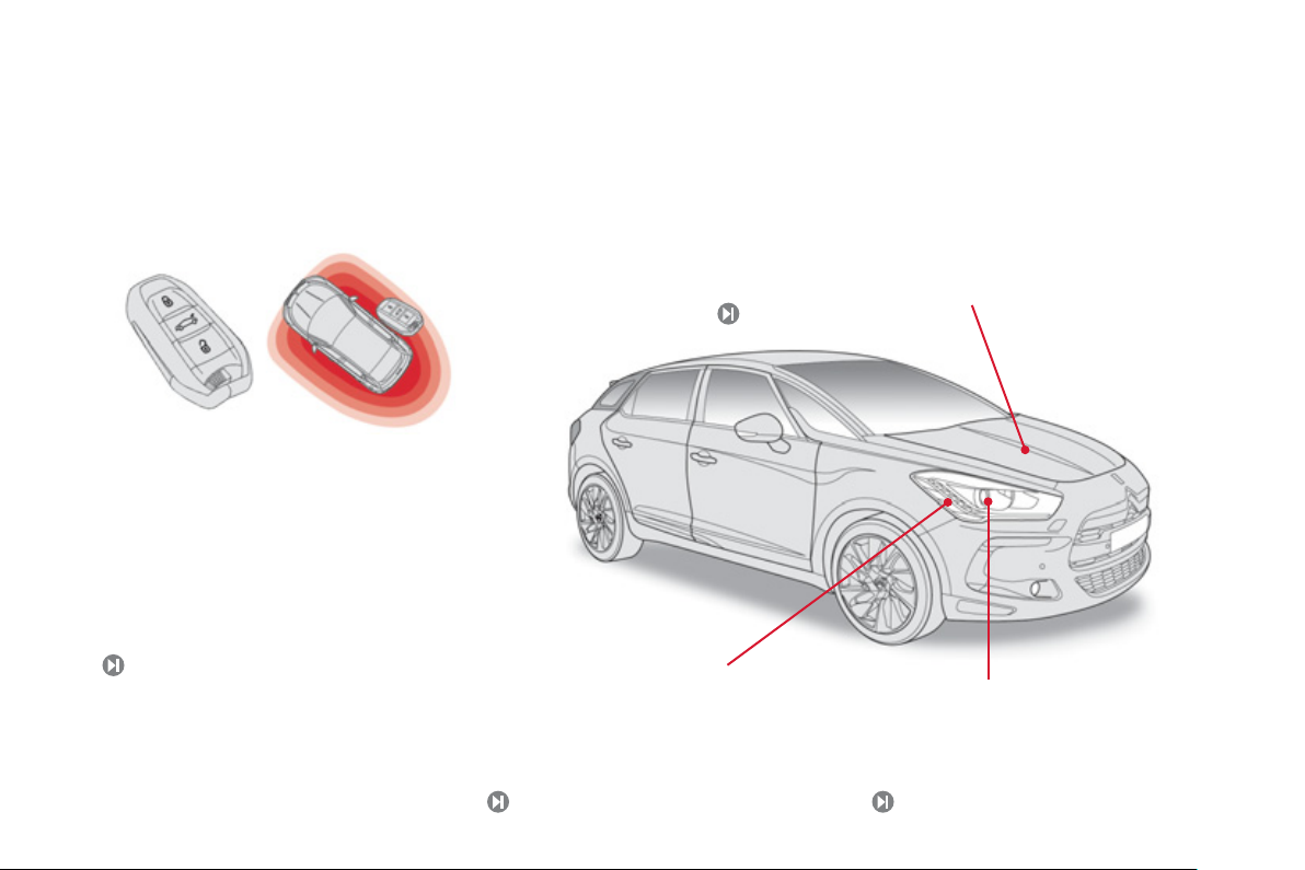
Electronic key: Keyless Entr
nd Startin
This system allows you to unlock, lock and start
our vehicle while keeping the key on your person
in the defined zone around the vehicle.
Stop & Start
This system puts the engine temporarily into standby during stops
in the tra
automaticall
s
the com
ic (red lights, traffic jams, etc...). The engine restarts
as soon as you want to move off. The Stop & Start
stem reduces fuel consumption and exhaust emissions, and offers
ort of complete silence when stationary.
8, 9
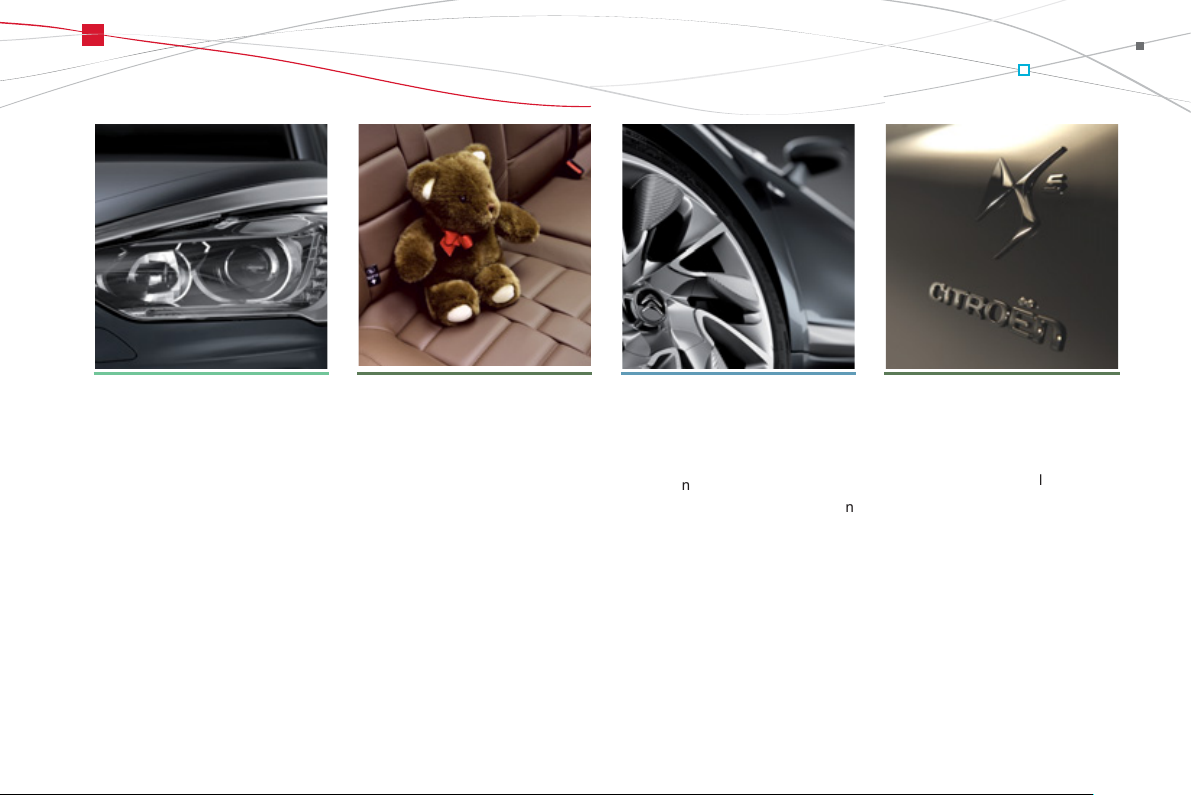
Daytime running lamps
This lighting, switched on automatically when
startin
the engine, makes your vehicle more
vi
r r
.
Directional lighting
This lighting automatically provides additional
orward visibility when cornering.
14
Page 11
Familiarisation
g
g
g
e
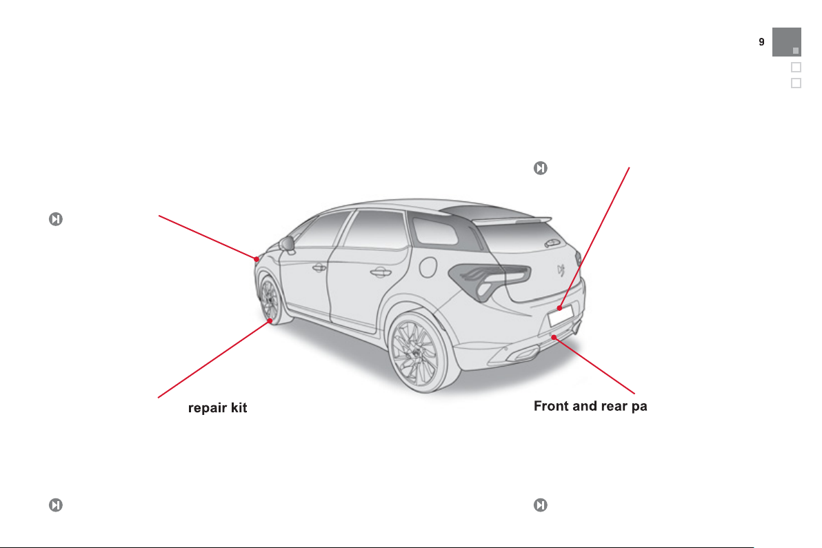
Front and rear parking sensors
obstacles located
e
7
Temporary puncture repair kit
c
y
0
igati
lly
engaging
i
colour scree
Exterior
Automatic headlamp dippin
This system automatically changes between
dipped and main beam, dependin
drivin
conditions, using a camera located in
th
interior rear view mirror.
137
This kit is a complete system consisting of a
ompressor and a sealant cartridge, to allow
the temporar
repair of a tyre.
on the
Reversing camera
This system, available only with satellite
nav
on, is activated automatica
reverse gear and provides an image
n the
129
This systems warns you of the presence of
vehicle during parking manoeuvres.
n.
in front of or behind th
on
18
12
Page 12
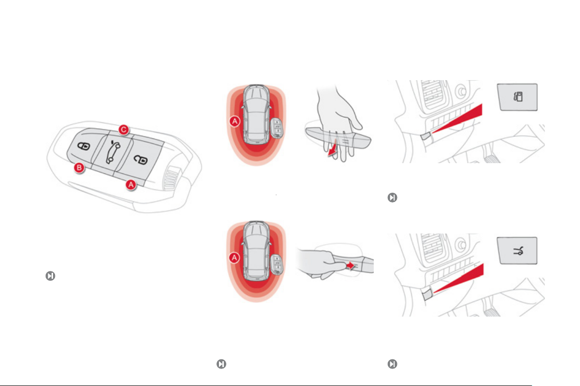
Access
1.
y
g
e de
A
around the vehicle, pass
y
A
(
ehicle
y
4
A.
B.
C.
of
49
1.
)
6
Electronic ke
Keyless Entry and Starting
Fuel tank
Unlocking the vehicle.
Normal locking of the vehicle
Unlocking the boot and complete unlocking
the vehicle.
8
Unlockin
With the electronic key on your person and in
th
fined zone
our hand behind the door handle to unlock the
vehicle, then pull on the handle to open the door.
Opening the fuel filler flap.
Tank capac i t
63
: approximately 60 litres.
Boot
Locking
With the electronic key in the defined zone
around the vehicle, press with a finger on
the door handle
v
.
at the markings) to lock the
Unlocking the boot (maintain pressure until
the boot is heard to unlock
5
.
Page 13
Familiarisation
y
s
y
n
y
(
gy
US
s
y
yWay
8
99
5
p
y
a
a
appli
ibl
97
Interior
Head-up displa
This system projects speed and cruise control/
peed limiter information onto a smoked strip
in the driver's field of vision, so that the
eed to take their eyes off the road.
120
Massage function
This system provides a lumbar massage for a
eriod of about 60 minutes. The massage is
done in 6 c
cles of 10 minutes.
do not
Electric parking brake
It combines the functions of automatic
pplication on switching off the engine and
utomatic release when moving off. Manual
cation and release remains poss
e.
Audio and communication
systems
These systems benefit from the latest
technolo
atellite navigation system with colour screen,
auxiliar
eM
Audio system
: MP3 compatible audio systems,
B player, Bluetooth hands-free system,
inputs, Hi-Fi audio system,...
24
2
Central storage containing
various systems
It is illuminated, cooled and provides storage
and locations for s
USB Player , location for 0.5 litre bottle, ...).
7
stems and loose items
Page 14
Switch panels
eac
4
6
7
1
ec
161
1
g
137
9
5
c
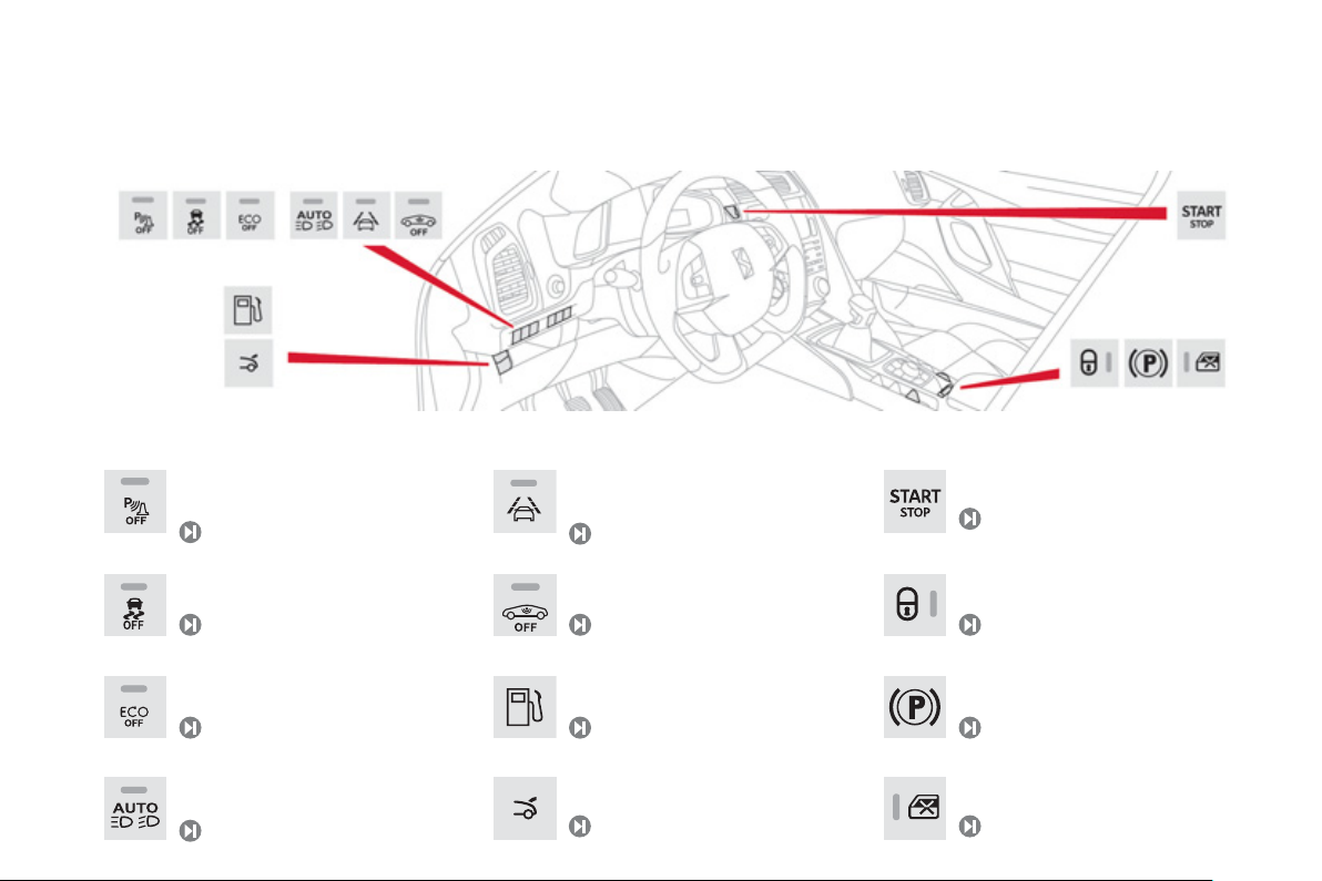
Lighting of the indicator lamp indicates the state of the corresponding function.
Deactivation of parking sensors.
28
Deactivation of the DSC system.
69
Deactivation of Stop & Start.
Activation of Automatic headlamp
dippin
.
Activation of lane departure warning.
11
tivation of the alarm.
D
57
Opening the fuel filler flap.
63
Opening the boot.
8, 5
Push button starting/stopping.
94
Locking/unlocking the passenger
ompartment.
5
Electric parking brake activated.
9
tric child lock.
El
Page 15
13
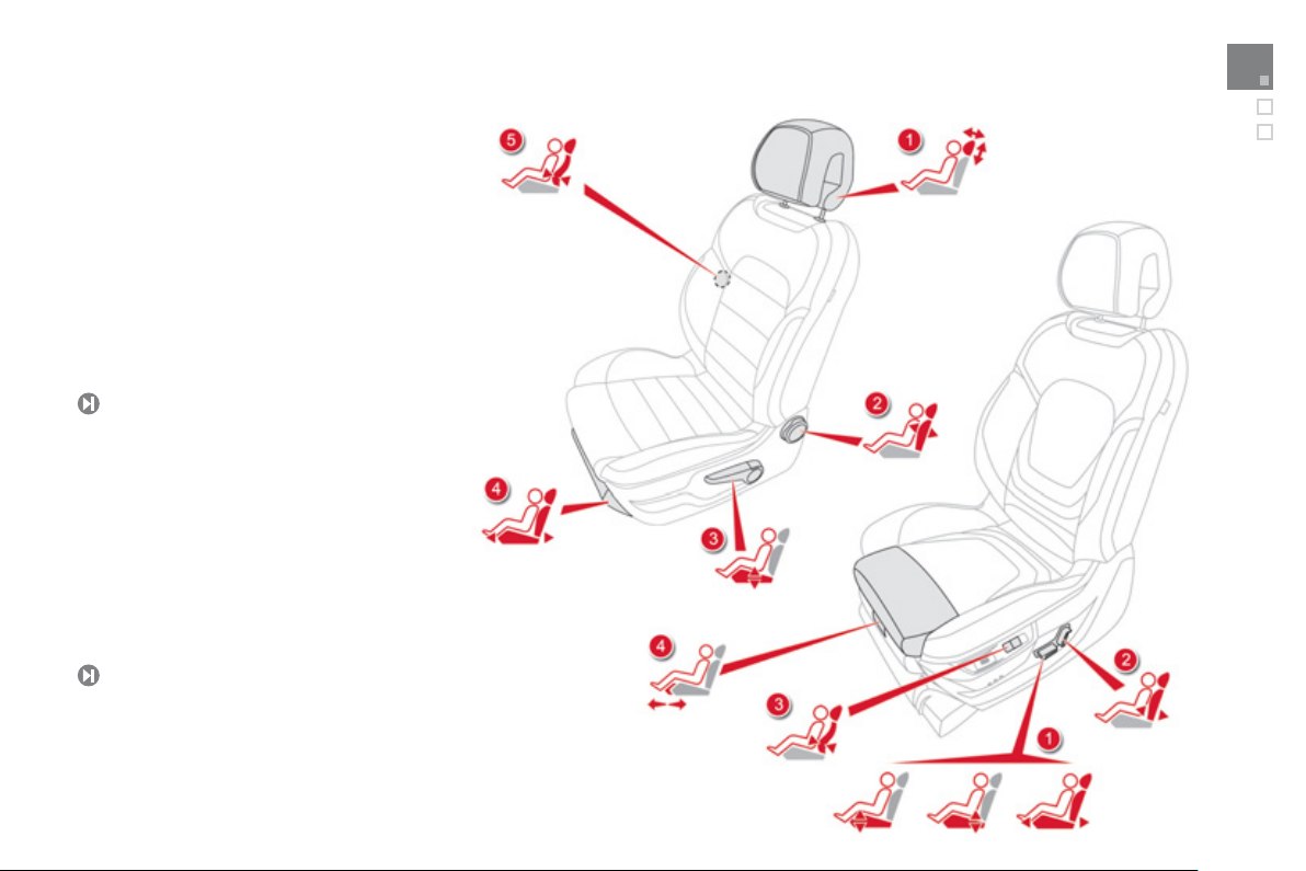
Sitting comfortably
8
1.
adj
2.
3.
4.
.
D
1.
j
2.
3.
D
Front seats
Manual
Head restraint height and angle
ustment.
Backrest angle adjustment.
Seat cushion height adjustment.
Seat forwards-backwards adjustment.
5
river's lumbar support adjustment.
6
Electrical
Angle, seat height and seat forwards-
backwards ad
Backrest angle adjustment.
river's lumbar support adjustment.
Manual cushion adjustment.
69
ustment.
Familiarisation
Page 16

s/elec
l
.
.
.
.
.
.
Cloc
.
S
.
.
.
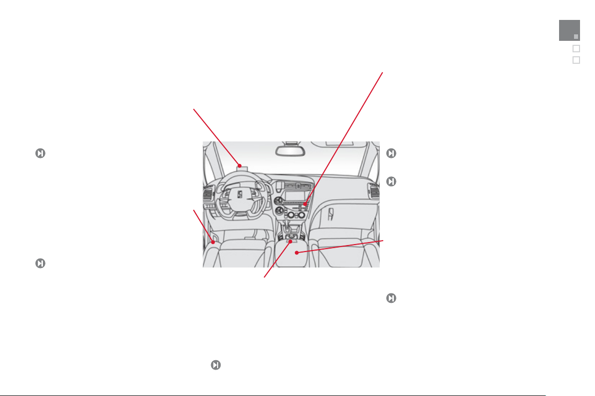
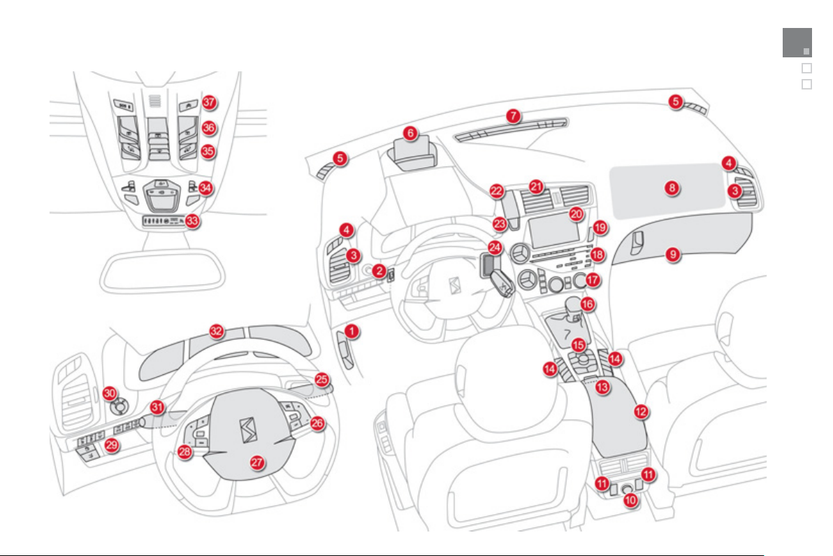
Instruments and controls
elease leve
2.
3.
4.
ents
5.
.
8.
P
9.
inside
10.
12
11.
12.
y
13.
o
28.
29.
30.
31.
32.
33.
34.
C
35.
Head
36.
C
37.
N
(
Bonnet r
Headlamp height adjustment.
Side adjustable air vents.
Front door window demisting/defrosting
v
.
Quarter light demisting windows.
6
Head-up display.
Windscreen demisting/defrosting vent.
assenger's airbag.
Glove box/Passenger's airbag deactivation
.
V accessory socket.
Rear electric window controls.
Central armrest with storage.
USB port/auxiliar
Electric parking brake.
r.
socket.
Controls for electric window
ock/central locking.
15
eMyWay controls.
16
Gear lever.
17
Heating/air conditioning controls.
18
Audio system.
19
Hazard warning lamps.
20
Multifunction screen.
Central adjustable air vents.
k.
23
tarting with the STAR T/STOP button.
24
Electronic key reader.
25
Wiper/screenwash/trip computer stalk.
26
Audio equipment steering wheel controls.
tric child
Driver's airbag.
rn.
H
Cruise control/speed limiter controls.
Switch panel (see previous page).
Door mirror adjustment.
Lighting and direction indicator stalk
Instrument panel.
Seat belt and airbag warning lamps.
ourtesy lamp.
-up display controls.
ontrols for glass roof panel blind.
CITROËNLocalised Emergency Call CITROË
depending on country of sale).
Localised Assistance Call
Page 17
1
Familiarisation
5
Page 18
Sitting comfortably
11.
.
3.
m
0
off
1
2
3
d
p
g
r
orwards
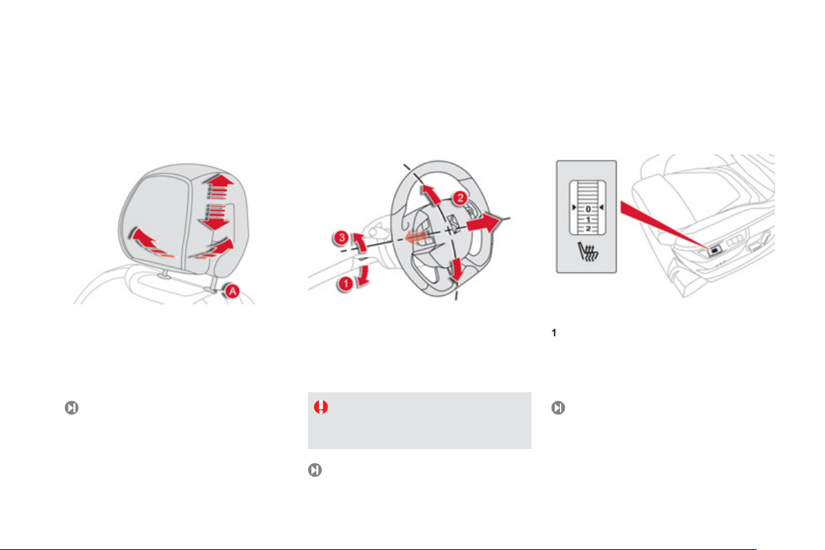
Head restraint adjustment
To lower it, simultaneously press button A an
ush down on the head restraint.
To raise it,
the desired position.
To incline it, swivel the lower part backwards o
f
uide the head restraint upwards to
.
7
Steering wheel adjustment
Release the adjustment mechanism.
2
Adjust for height and reach.
Lock the adjustment mechanism.
For reasons of safety, these operations
ust only be carried out with the
vehicle stationary.
77
Heated seats control
:
.
: low.
: medium.
: high.
72
Page 19
Sitting comfortably
Adj
1.
2.
3.
eselection o
lding th
6
0
Familiarisation
Door mirrors
ustment
Selection of the left or right mirror.
Adjusting the position of the mirror glass.
D
Fo
7
f the mirror.
e mirror.
Rear view mirror
1.Automatic detection of day/night mode.
Rear view mirror adjustment.
Front seat belts
Fastening.
Adjusting for height.
17
Page 20
Seeing clearly
g
.
.
.
O
A
owards
S
143
4
f
fog
a
S
3
Lightin
Wipers
Ring A
13
Lighting off.
Automatic illumination o
Sidelamps.
Dipped/main beam headlamps.
headlamps.
Control stalk A: windscreen wipers
2. Fast wipe.
1
Normal wipe.
Int
Intermittent wipe.
0
Park.
AUT
utomatic wiping.
Single wipe: Brief pull on the stalk
t
creenwash: Long pull on stalk towards you.
.
Ring B
Front and rear
134
lamps.
Switching on "AUTO" mode
Briefly push the stalk downwards.
Switching off "AUTO" mode
Briefly push the stalk downwards or place
the stalk in another position: Int, 1 or 2.
145
Ring B: rear wiper
P
rk.
Intermittent wipe.
creenwash.
14
Page 21
19
Monitoring
e
.
g
.
g
d
2.
g
g
concerned
C.
l
screen should
f
whic
1
Familiarisation
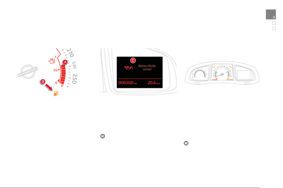
Instrument panel
On switching on, the dial needles go to the
xtent of their travel then return to 0.
A
With the ignition on, the bars indicate the
fuel remainin
B
With the engine running, the associated
low level warnin
.
lamp should go off.
With the ignition on, the instrument pane
I
the levels are not correct, top up the level
h is low.
63, 4
indicate the oil level.
Warning lamps
With the ignition on, the orange and re
warning lamps come on.
With the engine running, these warnin
lamps should go off.
If a warnin
lamp remains on, refer to the page
.
29
Page 22
Passenger safety
1.
2.
(
(
sea
seat be
C
seat be
g
F
d
g
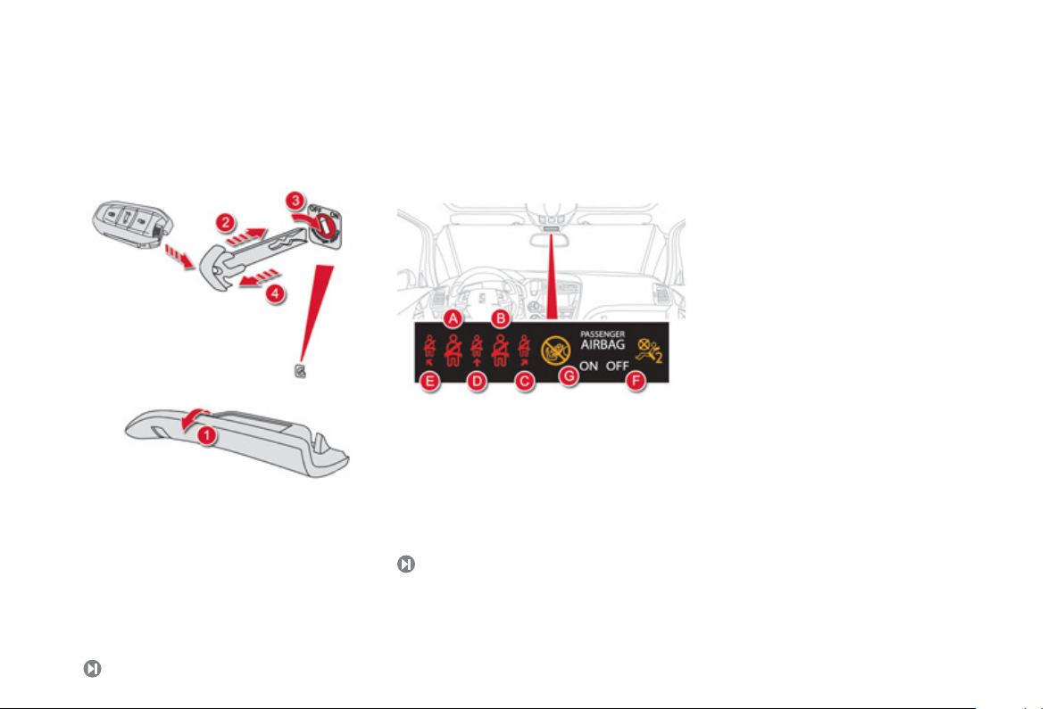
Front passenger's airbag
Open the glove box.
nsert the key (integral with the electronic key).
Select position:
"ON"
activation), with front passenger or
orwards facing" child seat,
"OFF"
deactivation), with "rear facing"
hild
t.
Remove the key keeping the switch in the
ew position.
174
Front seat belts and
assenger's front airbag
A. Left hand front
nfastened warning lamp.
Right hand front seat belt not fastened or
nfastened warning lamp.
Right hand rear seat belt not fastened or
nfastened warning lamp.
entre rear seat belt not fastened or
nfastened warning lamp.
lt not fastened or
Left hand rear
unfastened warnin
ront passenger's airbag deactivate
warning lamp.
Front passenger's airbag activated warnin
lamp.
lt not fastened or
lamp.
Page 23
he i
g
eased
g
A
g)
e
ehicle
g
Driving safely
e
of
e
ible by
lling
lly
leave a child alone i
ehicle
A
*
ess
accelerator and release
With th
g
y
f
f
ess
P
butto
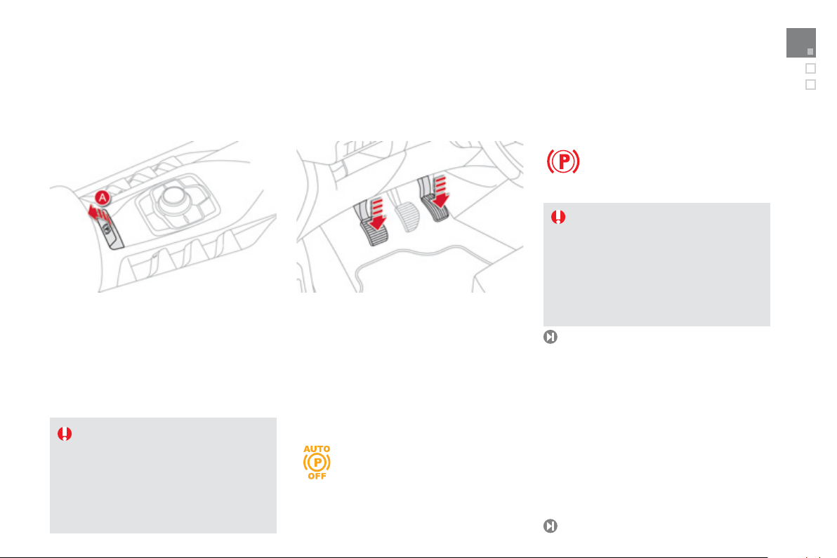
Electric parking brake
Manual Application/Release
Manual application of the parking brake is
With the ignition on,
ossible by
arking brake is poss
rake pedal and
ntrol lever A .
ulling the control lever
anual releas
ressing the
u
then
On opening the driver's door with the
ngine running, if an audible signal
s heard, apply the parking brake
manua
.
Do not
with the ignition on; they might release
the parking brake.
th
eleasing the
n the v
utomatic Application/Release
Pr
the
manual gearbox), the parking brake is released
utomatically and progressively as you move off.
e vehicle stationary, the parking brake
s applied automatically on switching off the
engine.
If this warning lamp comes on in
t
nstrument panel, automatic
* Accordin
pplication/release is
The parkin
nd rel
to country of sale.
brake must be applied
the clutch
eactivated .
.
Familiarisation
Before leaving the vehicle, check that
the the brake warnin
warning lamp in the control lever
re on fixed (not flashin
If towing a trailer or caravan or if the
lope might vary (transport by boat or
orry, recovery of the vehicle...) make
a maximum application of the parking
brake - by making a long pull on the
ntrol lever
v
7
- to immobilise th
.
lamp and the
Startin
- Insert the electronic key in the reader or
with Ke
less Entry and Starting, keep the
ectronic key in the vehicle.
- Press the brake pedal
with automatic or electronic gearboxes
or
ully declutch on vehicles with manual
earbox.
- Pr
the START/STO
irmly on vehicles
n.
Page 24
Driving safely
g
3
.
S
.
g
g
.
y
I
g
pp
7
y
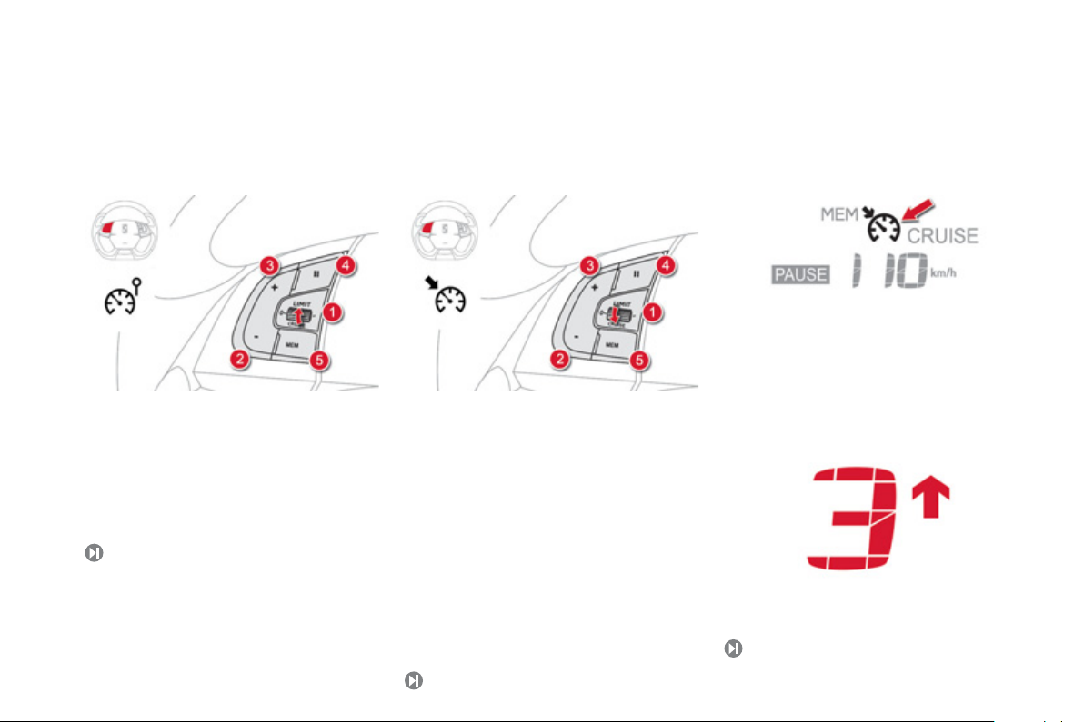
Speed limiter "LIMIT"
Cruise control "CRUISE"
Display in the instrument panel
The cruise control or speed limiter mode
a
ears in the instrument panel when it is
lected.
Selecting speed limiter mode.
Decrease the programmed value.
Increase the programmed value.
Pause/resume speed limiter.
Display of the memorised speeds (by the
udio system memory).
These values must be set with the en
12
ine running.
1
electing cruise control mode.
2
Programming a speed/Decrease the
pro
rammed value.
Programming a speed/Increase the
pro
rammed value.
Pause/resume cruise control.
5
Display of the memorised speeds (by the
audio s
n order to be programmed or activated, the
vehicle speed must be higher than 25 mph
40 km/h), with at least 4th gear engaged on
a manual
ear control or automatic gearbox).
stem memory).
earbox (2nd gear on an electronic
25
Gear shift indicator
The system may suggest, when appropriate,
that
ou change up a gear.
10
Page 25
Driving safely
6
g
x
d
7
g
g
g
d
iti
or engage reverse
S
y
y
g
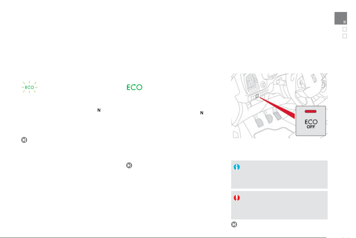
Stop & Start
Familiarisation
Going into engine STOP mode
peeds below 5 mph (8 km/h), press the brake
edal or put the gear lever in position
In certain circumstances, the STOP mode
lashes for a few seconds, then goes off.
The
ECO" warning lamp comes
on in the instrument panel and the
en
ine goes into standby; with the
lectronic gearbo
ay not be available; the
11
system an
ECO" warning lamp
Going into engine START mode Deactivation/Reactivation
The "ECO" warning lamp goes off
and the en
lectronic gearbox system:
- with the
elease the brake pedal,
- or with the
rake pedal released, move the gear lever
to pos
-
In certain circumstances,
nvoked automatically; the
lashes for a few seconds, then goes off.
on
17
ine restarts with the
ear lever in position A or
ear lever in position
or
,
.
TAR T mo d e may be
ECO" warning lamp
an
You can deactivate the s
pressing the "ECO OFF" button; the button's
warnin
lamp comes on.
The system is automatically reactivated
very time the engine is started with
the STAR T/STOP button.
Before refuelling or doing anything
nder the bonnet, you must switch
off the ignition with the START/STOP
tton.
11
stem at any time b
Page 26

Eco-driving
CO
emissions
ily
y
)
by
g
S
g
fue
Eco-driving is a range of everyday practices that allow the motorist to optimise their fuel consumption and
Optimise the use of your
earbox
With a manual gearbox, move off gently,
ange up without waiting and drive by
hanging up quite soon. If your vehicle has
the system, the gear shift indicator invites you
to change up; it is displayed in the instrument
anel, follow its instructions.
With an automatic or electronic gearbox,
tay in Drive
the type of gearbox, without pressing the
ccelerator pedal heav
D"or Auto
A" , according to
or suddenly.
Drive smoothl
Maintain a safe distance between vehicles, use
ngine braking rather than the brake pedal,
nd press the accelerator progressively. These
ractices contribute towards a reduction in fuel
onsumption and CO emissions and also helps
educe the background traffic noise.
If your vehicle has cruise control, make use of
the system at speeds above 25 mph (40 km/h
when the traffic is flowing well.
Control the use of your electrical equipment
Before moving off, if the passenger
ompartment is too warm, ventilate it
opening the windows and air vents before using
the air conditioning.
Above 30 mph (50 km/h), close the windows
and leave the air vents open.
Remember to make use of equipment that can
help keep the temperature in the passenger
ompartment down (sunroof and window
linds...).
Switch off the air conditioning, unless it has
automatic digital regulation, as soon as the
desired temperature is attained.
Switch off the demisting and defrostin
ontrols, if not automatic.
Switch off the heated seat as soon as possible.
witch off the headlamps and front foglamps
when the level of light does not require their
.
Avoid running the engine before moving off,
articularly in winter; your vehicle will warm
up much faster while driving.
As a passenger, if you avoid connecting
our multimedia devices (film, music, video
ame...), you will contribute towards limitin
the consumption of electrical energy, and so
Disconnect your portable devices before
leaving the vehicle.
.
l.
Page 27

Familiarisation
S
ibl
oads ca
use
C
5
Limit the causes of excess
onsumption
pread loads throughout the vehicle; place
the heaviest items in the bottom of the boot,
as close as poss
Limit the l
reduce wind resistance (roof bars, roof rack,
bicycle carrier, trailer...). Use a roof box in
reference.
Remove roof bars and roof racks after
At the end of winter, remove snow tyres and
refit your summer tyres.
e to the rear seats.
rried in the vehicle and
.
Observe the recommendations
n maintenance
Check the tyre pressures regularly, when cold,
eferring to the label in the door aperture,
river's side.
arry out this check in particular:
- before a long journey,
- at each change of season,
- after a long period out of use.
Don't forget the spare wheel and the tyres on
ny trailer or caravan.
Have your vehicle serviced regularly (engine
oil, oil filter, air filter...) and observe the
schedule of operations recommended by the
nufacturer.
When refuelling, do not continue after the 3
ut-off of the nozzle to avoid any overflow.
At the wheel of your new vehicle, it is only
after the first 1 800 miles (3 000 kilometres)
that you will see the fuel consumption settle
down to a consistent average.
Page 28

001
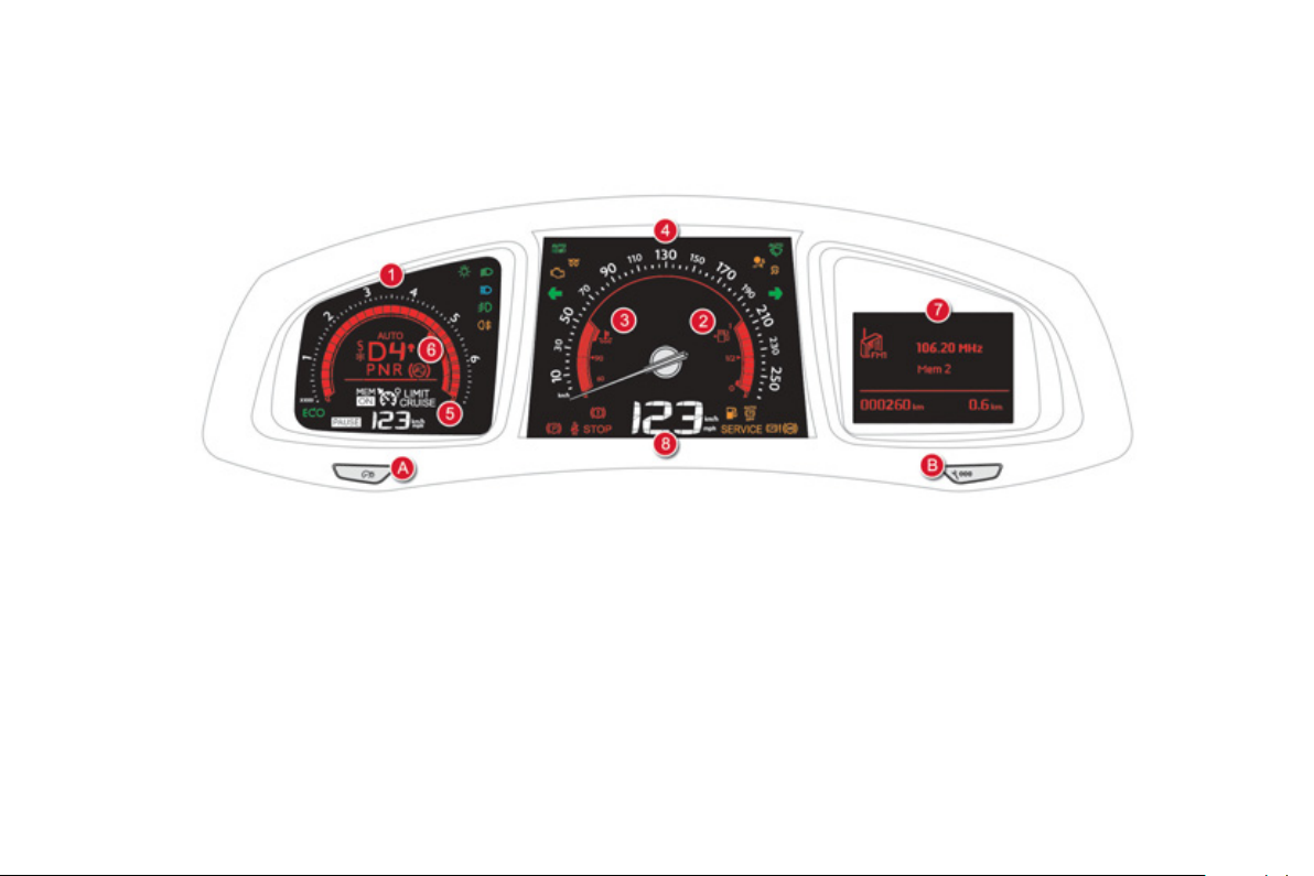
Instruments and controls
Page 29
Page 30
Petrol-Diesel instrument panel
.
g
g
(
.
.
g
i
lli
Dial
s and screens Control buttons
Rev counter (x 1 000 rpm or tr/min),
raduation according to engine (petrol or
iesel).
Fuel gauge.
Engine coolant temperature gauge.
Speedometer (mph or km/h).
Cruise control or speed limiter settings.
6
Gear shift indicator for a manual gearbox
r gear lever position and gear for an
lectronic gearbox system or automatic
earbox.
7
Instrument panel screen: trip recorder,
alert messa
e.g.: oil pressure, battery, door open, ...),
tr
p computer, media, sate
Digital speedometer (mph or km/h).
es or state of functions
te navigation.
A.Main lighting and controls dimmer.
B
- Successive short presses: under-inflation
detection, recall servicin
lert log.
- Lon
press: set the function selected to
zero
service indicator or trip recorder).
information,
Page 31

Indicator and warning lamps
Wh
f
A
g
g
fau
occurred
p
g
Monitoring
Visual indicators informing the driver that a
stem is in operation, switched off or has a
lt.
When the ignition is switched on
Certain warning lamps come on for a few
econds in the instrument panel and/or
instrument
i
nition is switched on.
anel screen when the vehicle's
en the engine is started, these same
arning lamps should go off.
I
they remain on, before moving off, refer to the
nformation on the warning lamp concerned.
ssociated warnings
The switching on of certain warning lamps may
be accompanied by an audible signal and a
messa
e in the instrument panel screen.
The warnin
fixed) or flash.
lamps may come on continuously
Certain warning lamps may come on in
one of two modes: fixed (continuous) or
flashing.
Only by relating the type of illumination
to the operation of the vehicle can it
determined whether the situation is
normal or a
Refer to the tables on the following
pages for more information.
lt has
.
Page 32

Operation indicator lamps
e
e
A
f
ps
fixed
The lighting
S
ed
g
fixed
g
pp
s
fixed
f
g
A
fixed
The lighting
"Di
d
Th
hori
g
g
If one of the following indicator lamps comes on in the instrument panel and/or instrument panel screen, this confirms that the corresponding system has come into operation.
Warning/indicator lamp
Left-hand
irection indicato
Right-hand
irection indicator
Sidelam
ipped beam
eadlamps
ain beam
headlamps
utomatic
eadlamp
dipping
Front foglamp
tat
lashing with buzzer. The lighting stalk is pushed down.
flashing with buzzer. The lighting stalk is pushed up.
.
.The li
fix
.The li
.
.The
Caus
"
idelamps" position.
eam headlamps" position.
u.
eam headlamps" position.
Its warning lamp is on.
stalk is in the
hting stalk is in the "Dipped
hting stalk is pulled towards
stalk is in the
ront foglamps are switched on. Turn the ring on the stalk rearwards twice to switch off
For more information on the lighting controls, refer to the "Visibility" section.
ppe
ction/Observations
Pull the stalk to return to di
e camera, located in the interior rear view mirror,
aut
ses or not switching between main and dipped
beam, depending on the exterior lighting and the
drivin
conditions.
Pullin
the lighting stalk to return to dipped beam.
the front fo
lamps.
ed beam headlamps.
Page 33

3
1
g
e
e
fixed
The
has bee
g
e
g
e elec
O
f
f
g
ke
automatic release" functions are
g
Monitoring
Warning/indicator lampStat
Rear foglamps fixed. The rear foglamps are switched on. Turn the ring on the stalk rearwards to switch off the
esel engine
re-heating
lectric parking
rak
eactivation of
he automatic
unctions of the
ectric parkin
ra
.
fixed. The electric parking brake is applied. Release the electric parking brake to switch off the
fixed. The "automatic application"
Caus
TART/STOP switch
ressed (ignition on).
on switching off the engine) and
"
deactivated or faulty.
Action/Observations
rear fo
lamps.
n
Wait until the warnin
Once it goes off, starting is immediate, on condition
that the brake pedal remains pressed for automatic or
ectronic gearboxes, or the clutch pedal is pressed
ully down for manual gearboxes.
The period of illumination of the warning lamp is
determined by the ambient conditions (up to about
thirty seconds in extreme conditions).
If the engine does not start, switch the ignition off and
then on, wait until the warning lamp goes off again,
then start the engine.
warnin
lamp: with your foot on the brake pedal, pull
th
tric brake control lever.
bserve the safety recommendations.
For more in
re
er to the "Driving" section.
Activate the function (according to country) via the
vehicle configuration menu or contact a CITROËN
dealer or a qualified workshop if automatic application/
release is not possible.
The parking brake can be released manually usin
the emergency release procedure.
For more information on the electric parking brake,
refer to the "Driving" section.
ormation on the electric parking brake,
lamp goes off before starting.
Page 34

Warning/indicator lamp Stat
e
e
A
A
g
A
g
fixed
seat be
Th
he gl
e
g
Move the co
g
y
t
fixed
j
y
ashes for a fe
O
ailable
or
S
ode is
ed
lly
g
STO
utomatic
wipin
fixed. The wiper control is pushed
Caus
wnwards.
ction/Observations
utomatic front wiping is activated.
To deactivate automatic wipin
talk downwards or put the stalk into another position.
, operate the control
assenger's
rbag system
Stop & Star
in the
nd passenger's front
rbag warning lamps
display.
. When the vehicle stops (red lights,
fl
econds, then goes
.
lt
e control switch, located in
ove box, has been placed in
t
ON" position.
th
The passen
tivated.
n this case, do not install a "rear
acing" child seat.
traffic
stem has put the engine into STOP
w
ST
nav
TAR T m
utomatica
er's front airbag is
ams,...) the Stop & Start
.
P mode is temporarily
.
invok
.
deactivate the passen
In this case,
The warning lamp goes off and the engine restarts
automaticall
ve off.
Refer to "Drivin
with
ntrol switch to the "OFF" position to
er's front airbag.
ou can install a "rear facing" child seat.
in START mode, as soon as you want to
- § Stop & Star t" for special cases
P mode and STAR T mo d e.
Page 35

3
eactivation indicator lamps
dibl
e
e
fixed
f
g
y
Th
p
g
f
f
e DSC/AS
deac
SC
AS
SC/AS
g
SC/AS
he vehicle is started
f
If one of the following indicator lamps comes on, this confirms that the corresponding system has been switched off intentionally.
s is may be accompanied by an au
e signal and a message in the instrument panel screen.
3
Monitoring
Warning/indicator lampStat
Caus
assenger's
irbag system
SC/ASR fixed. The button, located at the bottom
in the instrument
anel and/or seat belt
and
ront passenger's
airba
warning lamps
displa
.
e control switch, located in the
glove box, is set to the OFF
The passen
le
t of the dashboard, is pressed. Its
ndicator lamp is on.
Th
D
R: anti-slip regulation.
er's front airbag is
tivated.
R is
: dynamic stability control.
tivated.
osition.
Action/Observations
Set the control to the
assenger's front airbag.
In this case, do not
osition.
Press the button to activate the D
lamp
oes off.
The D
t
I
deactivated, the system is reactivated automatically
rom around 30 mph (50 km/h).
R system is activated automatically when
ON"position to activate the
it a child seat in the rear-facing
R. Its indicator
.
Page 36

When the engine is running or the vehicle is being driven, illumination of one of the following warning lamps indicates a fault which requires action on
f
Any f
y
e
e
A
P
dibl
h
g
out
g
f
e
fau
occurred fo
g
fy
fixed
f
fy
C
f
,
)
ily with
g
y
g
fixed.This indicates the low level i
he
esel add
eservo
y
the part o
If
the driver.
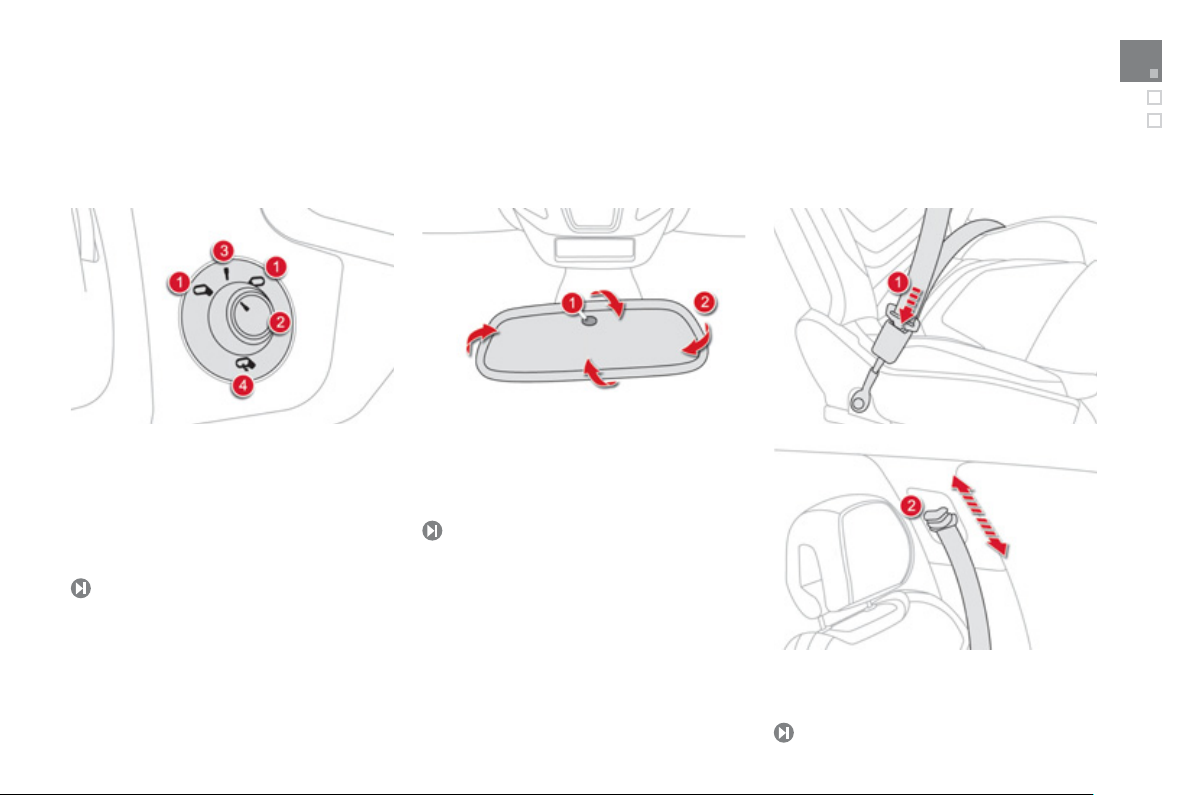
ault resulting in the illumination of a warning lamp must be investigated further by reading the associated message in the instrument panel screen.
ou encounter any problems, contact a CITROËN dealer or a qualified workshop.
Warning/indicator lamp Stat
STO
ervic
PEF: particle
missions filter
iesel
Caus
fixed, associated with
nother warning lamp,
ccompanied by an
u
e signal and a
essage in the screen.
on temporarily. A minor
. A major fault has occurred for which
fixed, associated
temporar
essage on the risk of
blocka
a
e of the PEF.
It is associated with a punctured
wheel, the braking system, the power
teering, the engine oil pressure,
t
e engine coolant temperature or a
ajor electrical fault.
there is no specific warnin
there is no speci
This indicates the start of saturation
of the particle emissions filter.
Di
lt has
ic warning lamp.
itive r
r which
lamp.
n t
ir.
ction/Observations
Stop as soon as it is safe to do so as the en
.
Park, switch off the i
dealer or a quali
the fault by reading the message shown in the
Identi
creen, such as, for example:
- the closing of the doors, boot or bonnet,
- the engine oil level,
- the screenwash level,
- the remote control battery,
- the tyre pressures,
- saturation of the particle emission filter (Diesel).
For any other faults, contact a CITROËN dealer or a
qualified workshop.
the fault by reading the message shown
Identi
on the screen and contact a
quali
ied workshop.
As soon as traffic conditions allow, regenerate the
filter b
driving at a speed of at least 35 mph (60 km/h)
until the service warnin
Have the level topped up b
qualified workshop as soon as possible.
nition and call a CITROËN
ied workshop.
ITROËN dealer or a
lamp goes off.
a CITROËN dealer or a
ine may
Page 37

35
p
e
e
ke
Th
lied
lly
/
f
f
t
A
q
y
g
g
g
g
g
p
y
y
g
e electronic brake force dis
g
e
automatic release" functions are
g
f
/
ibl
g
g
Monitoring
Warning/indicator lam
ectric parking
ra
lectric parking
rake faul
eactivation of
e automatic
unctions of the
ectric parkin
rak
Brakin
tat
flashing.
fixed.
fixed. The "automatic application"
fixed. The braking system fluid level has
+ fixed, associated
with the ABS warnin
lamp.
Caus
e electric parking brake is not
app
automatica
The application
lone, the electric parking brake has
fault.
on switching off the engine) and
"
deactivated or faulty.
dropped si
Th
EBFD) system has a fault.
nificantly.
.
release is faulty.
tribution
Action/Observations
You must stop as soon as it is sa
Park on
Contact a CITROËN dealer or a
without dela
The parkin
For more information on the electric parkin
refer to the "Drivin
Activate the function (according to country) via the
vehicle confi
dealer or a quali
release is not poss
The parking brake can be released manually using the
For more information on the electric parkin
refer to the "Drivin
You must sto
Top up with brake fluid listed b
If the problem persists, have the s
You must stop as soon as it is safe to do so.
Have it checked by a CITROËN dealer or a qualified
workshop.
lat level ground, switch off the ignition and
ontact a CITROËN dealer or a qualified workshop.
.
brake can be released manually.
" section.
uration menu or contact a CITROËN
ied workshop if automatic application
e.
mergency release procedure.
" section.
as soon as it is safe to do so.
ITROËN dealer or a qualified workshop.
e to do so.
ualified workshop
brake,
brake,
CITROËN.
stem checked by a
Page 38

Warning/indicator lamp Stat
e
e
A
bility
l
)
ing
y
y of
fixed
)
y
m
g
fau
y
y
ksh
fixed
y
l
fixed
f
e
s
he
f
g
fue
ill
ff
y
y
g
A
)
au
g
y
y
Caus
ction/Observations
nti-lock
raking System
ABS
namic
sta
contro
DSC/ASR
ngine
utodiagnosis
syste
ow fuel leve
fixed. The anti-lock braking system has a
lt.
f
flashing. The DSC/ASR regulation is
. Unless it has been deactivated
flashing.The en
. The emission control system has a
with the two last
bars
lashing.
operat
on
Wh
tank.
.
button pressed and its indicator lamp
the DSC/ASR system has a fault.
ine management system has
lt.
lt.
n it first comes on there remain
uelin t
The vehicle retains conventional brakin
Drive carefull
ITROËN dealer or a qualified workshop without
dela
.
The s
directional stabilit
Have it checked b
workshop.
Risk of destruction of the catal
Have it checked b
wor
The warning lamp should go off when the engine is started.
If it does not go off, contact a CITROËN dealer or
qualified workshop without dela
You must re
t of
s warning lamp w
is switched on, until a su
Fuel tank capacit
Never continue to drive until
this could dama
stems.
at reduced speed and contact a
stem optimises traction and improves the
the vehicle.
a CITROËN or a qualified
a CITROËN dealer or a qualified
op.
uel as soon as possible to avoid runnin
l.
come on every time the ignition
icient addition of fuel is
.
: approximately 60 litres.
ou run out of fuel as
e the emission control and injection
.
tic conver ter.
.
Page 39

37
e
e
Airbag
ily
g
g
g
fixed
O
y
g
y
/
ed
g
g
A seat be
bee
been unfastened
Monitoring
Warning/indicator lampStat
Seat belt(s)
not fastened
nfastened
s on temporar
fix
r flashin
accompanied by an
audible si
irectional
headlamps
flashin
Caus
nal.
. This lamp comes on for a few
.
. The directional headlamps system
the i
lt has not
econds when you turn on
nition, then goes off.
ne of the airbag or seat belt
retensioner systems has a fault.
a fault.
n fastened or
.
Action/Observations
Pull the strap then insert the tongue in the buckle.
This lamp should
If it does not
ualified workshop.
Have it checked b
workshop.
Have it checked b
workshop.
o off when the engine is started.
o off, contact a CITROËN dealer or a
a CITROËN dealer or a qualified
a CITROËN dealer or a qualified
Page 40

oolant temperature gauge
one
one
Y
.
h
q
p
f
h
"MAX"
With the engine running:
- in z
- in z
ou MUST stop as soon as it is safe to do so
Wait a few minutes before switching off
t
e engine.
Contact a CITROËN dealer or a
worksho
A , the temperature is correct,
, the temperature is too high; the
ntral STOP warning lamp comes on,
ccompanied by an audible signal and a
essage in the instrument panel screen.
ualified
.
A
ter driving for a few minutes, the temperature
and pressure in the cooling system increase.
To top up the level:
wait for the engine to cool,
unscrew the cap by two turns to allow the
pressure to drop,
when the pressure has dropped, remove
t
e cap,
top up the level to the
Be aware of the risk of burns when
topping up the cooling system. Do not
fill above the maximum level (indicated
on the reservoir).
mark.
Page 41

Service indicator
)
Wh
Th
ese
he di
p
)
y
g
p
e ne
due
g
dicates
he ne
ice is due
f
e scree
g
e distance recorde
esumes
at a se
soo
System which informs the driver when the
ext service is due, in accordance with the
anufacturer's servicing schedule.
e point at which the service is due is
lculated from the last indicator zero r
s determined by two parameters:
- t
- the time ela
stance travelled,
sed since the last service.
t. It
More than 1 800 miles (3 000 km
emain before the next service is due
en the ignition is switched on, no service
nformation appears in the screen.
Between 600 miles (1 000 km
nd 1 800 miles (3 000 km) remain
efore the next service is due
For 5 seconds after the ignition is switched on, the
spanner symbolising the service operations comes
on. The distance recorder displa
distance remainin
Exam
le: 1 700 miles (2 800 km) remain before
th
xt service is
For 5 seconds after the i
reen in
before the next service is due.
.
:
line indicates the
nition is switched on, the
Monitoring
Less than 600 miles (1 000 km)
emain before the next service is due
xample: 400 miles (900 km) remain before
t
xt serv
For 5 seconds a
th
5 seconds after the i
th
operation.
th
n indicates:
he spanner remains on to indicate
rvice must be carried out
.
ter the ignition is switched on,
nition is switched on,
r r
its normal
n.
5 seconds after the ignition is switched on,
esumes its normal operation. The screen then
ndicates the total and trip distances.
; the distance recorder
Illumination of the key is accompanied
a message in the instrument panel
.
Page 42

Service overdue
p
dicate tha
ice
ibl
f
e scree
g
eas
ese
accou
he distance recorde
esumes its normal
p
ese
g
b
access
y ti
P
f
For 5 seconds after the ignition is switched on,
anner flashes to in
the s
ust be carried out as soon as poss
xample:the service is overdue by 186 miles
300 km).
For 5 seconds a
th
ter the ignition is switched on,
n indicates:
t the serv
e.
Service indicator zero reset
Retrieving the service
nformation
You can
an
me.
ress the trip distance recorder zero reset
tton.
The service in
econds, then disappears.
the service information at
ormation is displayed for a few
5 seconds after the ignition is switched on,
t
o
eration.
r r
he spanner remains on.
The distance remaining may be
weighted by the time factor, dependin
n the driving conditions.
Therefore, the spanner may also come
n if you have exceeded the two year
rvice interval.
After each ser vice, the service indicator must
r
t to zero.
The procedure for resettin
switch off the ignition,
press and hold the trip distance recorder
zero reset
switch on the ignition; the distance recorder
splay begins a countdown,
when the display indicates
the button; the spanner disappears.
Following this operation, if you wish to
disconnect the battery, lock the vehicle
nd wait at l
ro r
t to be taken into
utton,
to zero is as follows:
=0", release
t five minutes for the
nt.
Page 43

Engine oil level indicator
This is indi
he i
f
g
p
efe
sectio
ocate
f
2
Sy
h
s
seconds
-
g
he i
stem which informs the driver whether
e engine oil level is correct or not.
t
Thi
information is indicated for a few
when the ignition is switched on, after the
rvice information.
The level read will only be correct
if the vehicle is on level ground and
the engine has been off for more than
minutes.
Oil level correct
This is indicated by a message in
t
nstrument panel screen.
Oil level incorrect
t
I
the low oil level is confirmed by a check
sing the dipstick, the level must be topped up
to avoid dama
cated by a message in
nstrument panel screen.
e to the engine.
Monitoring
Oil level indicator fault
This is indicated by a message in
the instrument
a CITROËN dealer or a qualified workshop.
anel screen. Contact
Dipstick
R
r to the "Checks"
dipstick and the oil
There are
marks on the dipstick:
A= max; never exceed this
-
level,
the oil filler cap, usin
rade of oil suited to your
ngine.
n to l
iller cap on your engine.
= min; top up the level via
the
the
Page 44

h
igh
f
y
Sy
y
y
ff
p
ehicle is locked or unlocked
otal distance recorder
by the dri
eros appear
Trip distance recorder
ighting dimmer
stem which measures the total distance
travelled b
The total and trip distances are displa
thirty seconds when the ignition is switched o
when the driver's door is o
v
To c onform to legislation in the country
ou are crossing, change the units
of distance (miles or km) via the
onfiguration menu.
the vehicle during its life.
ened and when the
.
ed for
System which measures a distance travelled
uring a day or other period since it was reset
to zero
,
With the ignition on, press the button until
z
ver.
.
System for manual adjustment of the brightness
the instruments and controls in relation to
t
e exterior br
tness.
Activation
When the lighting is on:
press the button to change the brightness
o
the instruments and controls,
when the level of brightness required is
eached, release the button.
Deactivation
When the lighting is off, or in day mode on
vehicles fitted with da
ressing the button does not have any effect.
time running lamps,
Page 45

Monitoring
ff f
The i
f
g
g
MyWay
f
(
y
y
ith th
ched o
Black panel (black screen)
with e
System allowing certain screens to be switched
o
or night driving (available only with
MyWay).
nstrument panel remains on with the
vehicle speed, electronic gearbox gear
elected, cruise control or speed limiter
information, if in use, and the low fuel alerts i
If there is an alert or a chan
or to a settin
nterrupted.
.
e in a function
, the black panel mode is
For more information, refer to the
Audio and telematics" chapter,
MyWay section.
Clock
The analogue clock does not have an
adjustment button.
To set the time, re
the screen
The clock is s
nce the the setting has been confirmed in
the screen, the hands will turn to s
w
e screen, and each time the ignition is
wit
er to the section relating to
audio system) configuration menu.
nchronised with the screen time;
nchronise
n.
Page 46

Trip computer
Wh
e co
seconds
use
e
p
g
y
ess
g
f
S
ith
h
f
ge f
Tri
h
f
f
g
nstrument panel screen
Information displa
Pr
the button on the end of the wiper
ontrol stalk to display the various tabs in
ion.
Trip reset
- The current information tab with:
● the ran
● the current
● the
- Trip
● t
● the avera
-
● t
● the average
- Radio or media.
- Satellite navi
e,
uel consumption,
top & Start time counter.
" w
:
e average speed,
or the first trip.
uel consumption,
p
" with:
e average speed,
or the second trip.
uel consumption,
ation.
en the trip required is displayed, press
th
ntrol for more than two
r
the left hand thumb wheel of th
teering mounted controls.
Tri
s "1" and "2" are independent but their
is identical.
For example, trip
fi
ures, and trip "2" for monthly figures.
1" can be used for daily
Page 47

A few definitions…
(
)
ce
g
y
y
g
g
A
(mpg
g
A
(
g
(
/
y
g
Monitoring
5
Range
miles or km
This indicates the distan
which can still be travelled with
the fuel remainin
n relation to the average fuel
onsumption over the last few
iles (kilometres) travelled.
This value may vary following a change
in the style of driving or the relief,
resulting in a significant change in the
urrent fuel consumption.
When the range falls below 20 miles (30 km),
dashes are displa
litres of fuel, the range is recalculated and is
displa
ed when it exceeds 60 miles (100 km).
If dashes are displayed continuously
while driving in place of the digits,
ontact a CITROËN dealer or a
ualified workshop.
ed. After filling with at least
in the tank
Current fuel consumption
(mpg or l/100 km or km/l)
This is the avera
durin
the last few seconds.
This function is only displayed from
20 mph (30 km/h).
e fuel consumption
verage fuel
onsumption
or l/100 km or km/l)
This is the avera
onsumption since the last trip
omputer zero reset.
e fuel
verage speed
mph or km/h)
This is the avera
since the last trip computer zero reset
ignition on).
e speed calculated
Stop & Start time
ounter
minutes/seconds or hours
If
our vehicle is fitted with Stop & Start, a time
ounter calculates the time spent in STOP
mode durin
t resets to zero every time the ignition is
witched on with the STAR T/STOP button.
minutes)
a journey.
Page 48

002
Access
Page 49

Page 50

Electronic key
S
g of
used to locate and sta
e
e
g
y
seconds
doo
h
Hold the button do
ind
e boot unloc
g
e vehicle
g
remote control
ystem which permits central unlocking or
lockin
vehicle, as well as providing protection against
th
the vehicle using the lock or from a
istance. It is also
ft.
rt th
Unlocking the vehicle
Complete unlocking
Press the open padlock to unlock
th
.
Selective unlocking
This setting is done in the
onfiguration menu.
Complete unlockin
fault.
To unloc k only the driver's door,
ress the open padlock once.
To unlock the other doors and the boot,
press the open padlock a
Unlocking is confirmed by rapid flashing
the direction indicators for around
two
At the same time, depending on
version, the door mirrors unfold.
.
is activated b
ain.
nlocking the boot
Press this button until you hear
th
ompletely unlocked.
k. The vehicle is
ocking the vehicle
Press the closed padlock to lock
t
e vehicle completely.
w
ows close completely.
Locking is confirmed by fixed
ighting of the direction indicators for
approximately two seconds.
The
r mirrors fold at the same time.
Be aware of children when operatin
the windows.
wn until the
Page 51

Unlocking th
"Keyless Entry and Starting" system
g
I
ol" sectio
g
defined zone
pass your
behind the door handle to unlock the
g
y
g
Thi
y
h
as
he d
doo
e
g
y
Access
System that allows the opening, closin
and starting of the vehicle while keeping the
lectronic key on your person.
t can also be used as a remote control; see the
mote contr
n.
e vehicle
Complete unlockin
With the electronic key on your person
nd in the
nd
vehicle, then pull on the handle to open the
r.
You r pass e n
as soon as the electronic ke
fined zone around the vehicle.
ers can also open their doors,
,
is in the
Selective unlockin
s setting is done via the
onfiguration menu.
B
default, complete unlocking is
tivated.
To unlock only the drivers door, wit
the electronic key on your person, pass
our hand behind the driver's door handle
then pull on the door handle to open.
To unlock the complete vehicle, pass your
and behind one of the passenger door
ndles on the same side of the vehicle
the electronic key is located, then pull on
t
oor handle to open.
Unlocking is confirmed by rapid
lashing of the direction indicators for
approximately two seconds.
The
r mirrors unfold at the sam
time.
If the alarm is on, the audible warnin
when opening a door with the ke
integral with the remote control), will
top on starting the engine.
Page 52

Locking the vehicle
(
e vehicle
y
h
doo
doors o
boo
G
s
use the remote co
ol
g
f
y
seconds
With the electronic key in the defined
A , press with a finger on one of
the door handles
th
Maintain pressure with
t
e windows close completely.
Locking is confirmed by fixed
lighting of the direction indicators for
pproximately two seconds.
The
at the markings) to lock
.
our finger until
r mirrors fold at the same time.
Ensure that no one prevents the correct
operation of the windows.
Be aware of children when operatin
the windows.
If one of the
open or if the key for Keyless Entry and
tarting has been left inside the vehicle,
the central locking does not take place.
When the vehicle is locked, if it is
nlocked inadvertently, it will relock
automatically after about thirty seconds
nless a door is opened.
The folding and unfolding of the door
mirrors by the remote control can be
deactivated by a CITROËN dealer or a
ualified workshop.
r the
t is still
ocating your vehicle
unction allows you to identify
This
our vehicle from a distance,
articularly in poor light. Your vehicle
t be locked.
Press the closed padlock on the remote
ntrol.
This will switch on the courtes
irection indicators will flash for a few
As a safety measure (children on
board), never leave the vehicle without
taking the key for the Keyless Entry and
tarting system, even for a short period.
uard against theft when the key for
the Keyless Entry and Starting system
is in the defined zone with the vehicle
nlocked.
After a long period of parking,
the automatic detection function
of the key are inhibited so as to not
scharge the vehicle's battery. You
then
unction of the key to unlock the vehicle.
lamps and the
.
ntr
Page 53

5
1
g
It also deactivates the manual ce
al
deadlocked
Using th
l
y
g
seconds to close
y
g
ith
g
y
p
g
g
ehicle to be locked
g sy
one
gai
e seconds to deadloc
Access
Ignition on without startin
the engine (accessor
osition)
With the electronic key in the reader or the
Ke
less Entry and Starting key inside the
vehicle, pressin
w
no action on the pedals, allows the ignition
to be switched on and so activate the ancillary
uipment.
Using the ancillaries for a long period
introduces the risk of a flat battery.
the "STAR T/STOP" button,
Press the "STAR T/STOP" button,
the instrument
but the en
Press the button again to switch
off the i
v
anel comes on
ine does not start.
nition and so allow the
.
eadlockin
Deadlocking renders the exterior and
nterior door controls inoperative.
ntr
ntrol button.
Therefore, never leave anyone inside
the vehicle when it is
e remote contro
Press the closed padlock to lock
the vehicle completely.
Maintain pressure with
fin
er for more than
two
Press the closed padlock again within
fiv
Ensure that no one is preventing the
orrect closing of the windows.
Be aware of children when operating
the windows.
k the vehicle.
.
our
the windows.
With the Keyless Entry and
startin
By the doors:
With the electronic key in the defined
z
at the markings) to lock the vehicle.
Within five seconds, press the door handle
a
stem
A , press a finger on the door handle
n to deadlock the vehicle.
Page 54

Emergency procedure
The i
k
p
y f
g
he i
g
o unloc
y
T
seconds to deadloc
Emergency unlocking/locking
sing the integral key
ntegral key is used to lock and unloc
the vehicle when the electronic key cannot
o
erate:
- cell batter
or disconnected, ...
- vehicle located in an area with stron
electromagnetic signals.
Maintain a pull on button
t
lat, vehicle battery discharged
ntegral key
, to extract
Complete unlockin
Turn th e key towards the front of the vehicle
t
k the vehicle.
Normal locking
Turn the key towards the rear of the vehicle
to lock the vehicle completel
.
Deadlocking
Turn the key towards the rear in the driver's
oor lock to lock the vehicle completely.
urn the key towards the rear again within
ive
k the vehicle.
Page 55

5
3
y
y
Ë
f
g
f
f
ehicle
ehicle
Pl
S
/
f
p
Access
Remote control problem -
einitialisation
Following disconnection of the vehicle battery,
replacement o
in the event o
you can no longer unlock, lock or locate your
v
Place the mechanical key (integral with the
emote control) in the lock to unlock your
v
witch on the ignition by pressing STAR T
TOP.
The electronic key is
If the
dealer or a qualified workshop as soon as
ossible.
the remote control battery or
a remote control malfunction,
.
.
ace the electronic key in the reader.
ully operational again.
roblem persists, contact a CITROËN
Changing the battery of
the electronic ke
Battery ref.: CR2032/3 volts.
This replacement batter
CITRO
N dealer or a qualified workshop.
A message appears in the instrument panel
screen when replacement o
.
Unclip the cover using a small screwdriver
t the cutout.
Lift off the cover.
Remove the flat battery from its location.
Fit the new battery into its location
observin
Clip the cover onto the casing.
the original direction of fitment.
is available from a
the battery is
Do not throw the remote control
batteries away, they contain metals
which are harmful to the environment.
Take them to an approved collection
point.
Page 56

ost electronic key
Th
g
A
Visit a CITROËN dealer with the vehicle's registration document and your personal identification documents and if possible the key code label.
The CITROËN dealer will be able to retrieve the key code and the transponder code required to order a new key.
Electronic key
The electronic key is a sensitive system; do not operate it while it is in your pocket as there is a possibility that it may unlock the vehicle, without
ou being aware of it.
Do not repeatedly press the buttons of your electronic key out of range and out of sight of your vehicle. You run the risk of stopping it from
orking and the remote control would have to be reinitialised.
e electronic key cannot operate as a remote control when it is in the reader or even when the ignition is switched on.
Locking the vehicle
Driving with the doors locked may make access to the passenger compar tment by the emergency services more difficult in an emergency.
As a safety precaution (with children on board), take the Keyless Entry and Starting electronic key when you leave the vehicle, even for a short
time.
Electrical interference
The Keyless Entry and Starting electronic key may not operate if close to certain electronic devices: telephone, laptop computer, stron
magnetic fields, ...
nti-theft protection
Do not make any modifications to the electronic engine immobiliser system; this could cause malfunctions.
Don't forget to turn the steering to engage the steering lock.
When purchasing a second-hand vehicle
Have all of the keys in your possession paired by a CITROËN dealer, to ensure that only your keys allow your vehicle to be unlocked and started.
Page 57

Central locking control
A
y)
f
y
deadlocked o
Op
s allows
doors and
boo
doors
y
o
y
g
o
55
Access
erate the button.
Thi
r unlocked.
the
If the vehicle is
rom the outside, the button is not
active. In this case, use the remote
ontrol to unlock the vehicle or pull an
interior door handle to open a door.
If one of the doors is open, central
ocking from the inside does not take
place.
the
t to be locked
r locked
utomatic central locking of
the doors
anti-intrusion securit
The doors and boot can lock automatically
hile driving (speed above 6 mph (10 km/h)).
To activate or deactivate this
b
default:
Operate this button until a
essage appears in the
instrument panel screen.
Driving with the doors locked may make
ccess to the passenger compar tment
by the emergency services more
difficult in an emergency.
ransporting long or voluminous
objects
If you want to drive with the boot open,
ress the central locking control button
to lock the
unction (activated
.
Emergency control
System allowing the doors to be locked and
unlocked manuall
f the central locking system or battery failure.
Locking the driver's door
Insert the key in the door lock, then turn it
t
the rear.
You can also appl
the passen
Unlocking the driver's door
Insert the key in the door lock, then turn it
t
the front.
in the event of a malfunction
the procedure described for
er doors.
Page 58

Boot
ess this button until the boot is heard to
lock
andle
f
ing
or
g
(
p
boo
A
of
e
Sy
f
f
O
R
f
y
C
Pull the i
ill remain locked
Locking the front and rear
passenger doors
pen the doors.
On the rear doors, check that the child lock
s not on (see Child Safety).
emove the black cap, located on the edge
o
the door, using the key.
Insert the key in the socket without forcing
t, then without turning it, move the latch
sidewa
s towards the inside of the door.
Remove the key and refit the cap.
lose the doors and check that the vehicle
as locked correctly from the outside.
Unlocking the front and rear
passenger doors
nterior door opening control.
Opening from inside
Pr
n
.
Closing
Lower the tailgate using the interior grab
h
I
the tailgate is not closed correctly,
runn
mph (10 km/h)), a message appears in the
instrument
.
ehicle movin
anel screen for a few seconds.
speed above
ngine
ailgate release
stem allowing the mechanical unlocking of
the boot in the event o
locking system mal
Unlocking
Fold back the rear seats to gain access to
the lock from inside the
Insert a small screwdriver into hole
lock to unlock the tailgate.
Move the latch to the left.
Locking after closing
If the fault persists after closing again, the boot
w
a battery or central
unction.
t.
.
th
Page 59

g
g ty
Alarm
gg
l
f
g
e a
ude o
gg
oved or knocked
Acti
.
emote co
lock the vehicle
A
g
y
g
seconds and
ute and 30 seconds
f
g
y
e remote co
g
y
System which protects and provides a deterrent
a
ainst theft and break-ins. It provides the
followin
- Exterior perimeter
The system checks for opening of the vehicle.
The alarm is tri
oor, the boot or the bonnet...
- Interior volumetric
The system checks for any variation in the
vo
The alarm is triggered i
window, enters the passen
pes of monitoring:
ered if anyone tries to open a
ume in the passenger compartment.
anyone breaks a
er compar tment or
ves inside the vehicle.
- Tilt
The system checks for any change in
th
ttit
The alarm is tri
m
f the vehicle.
ered if the vehicle is lifted,
.
Self-protection function
The system checks for the putting out of
ervice of its components.
The alarm is triggered if the battery, the
button or the wires of the siren are put
out of service or damaged.
For all work on the alarm system,
ontact a CITROËN dealer or a
ualified workshop.
Locking the vehicle with full
larm system
vation
witch off the ignition and get out of the vehicle
Press the locking button on the
r
using the Keyless Entry and
ntrol or
tarting system.
Access
The monitoring system is active: the indicator
lamp in the button flashes once per second.
fter the locking button on the remote control
is pressed or the vehicle locked usin
Ke
less Entry and Starting system, the exterior
perimeter monitorin
5 seconds, the interior volumetric monitoring
ter 45
min
I
an opening (door, boot...) is not closed
ully, the vehicle is not locked but the exterior
perimeter monitorin
dela
of 45 seconds.
is activated after a delay
the anti-tilt after one
.
will be activated after a
the
Deactivation of the volumetric
onitoring
Press the unlocking button on
th
vehicle usin
and Starting system.
The volumetric protection system is
eactivated: the indicator lamp in the
utton goes off.
OFF
ntrol or unlock the
the Keyless Entr
57
Page 60

Locking the vehicle
y
eac
cases such as
g
g y
ging
having y
i
g
h
ly
g
ff
g
g
g
gg
e remote co
e
h
g.
lock the vehicle
ing the Keyl
The indi
f
g
ed
g
y
)
O
S
g
Lock
y
doo
y
Have it checked by a CITROËN dealer or a
y
*
door o
boo
s
lly
T
iggering th
f
e
with exterior perimeter
onitoring onl
D
tivate the interior volumetric and anti-lift
onitoring to avoid unwanted triggering of the
larm in certain
- leavin
- washin
- chan
-
- transportat
Deactivation of the interior
olumetric and anti-tilt monitorin
The exterior perimeter monitorin
ctivated: the indicator lamp in the button
lashes once per second.
To b e e
out each time the i
a window partially open,
our vehicle,
a wheel,
our vehicle towed,
on by sea.
Switch of the ignition and within
ten seconds, press this button
OFF
until the indicator lamp is on
ontinuously.
Get out of the vehicle.
Press the locking button on
t
e remote control immediate
or lock the vehicle using the
eyless Entry and Starting
stem.
ective, this deactivation must be carried
nition is switched off.
:
alone is
Reactivation of the interior
olumetric and anti-tilt monitorin
Press the unlocking button on
OFF
th
vehicle using the Keyless Entry
nd Starting system to deactivate
t
e exterior perimeter monitorin
Press the locking button on the
mote control or
us
tarting system to activate all the
onitoring functions.
cator lamp in the button
again
lashes once per second.
ntrol or unlock th
ess Entry and
Triggering of the alarm
This is indicated by sounding of the siren and
lashing of the direction indicators for thirty seconds.
The monitorin
the alarm has been tri
OFF
amp in the button informs you that the alarm
was triggered during your absence. When
the i
immediatel
functions remain active until
ered eleven times in
ion.
When the vehicle is unlocked usin
the remote control or unlock
using the Keyless Entry and Starting
stem, rapid flashing of the indicator
nition is switched on, this flashing stops
.
Failure of the remote control
To deactivate the monitoring functions:
Unlock the vehicle using the key (integral with
the remote control
pen the door; the alarm is triggered.
witch on the ignition; the alarm stops.
The indicator lamp in the button
in the driver's door lock.
Locking the vehicle without
ctivating the alarm
or deadlock the vehicle using the ke
integral with the remote control) in the
river's
r lock.
Operating fault
When the ignition is switched on, fixed
illumination of the indicator lamp in the button
indicates a fault in the s
ualified workshop.
stem.
Automatic activation *
2 minutes after the last
osed, the system is activated automatica
o avoid tr
the vehicle,
n the remote control or unlock the vehicl
using the Keyless Entry and Starting
stem.
According to country.
irst press the unlocking button
r the
e alarm on entering
oes off.
t i
.
Page 61

9
Electric windows
.
.
.
T
eased
g
The electric window switches remai
O
.
.
,
).
eft hand front electric window switch
ight hand front electric window
switch
ight hand rear electric window switch
4
eft hand rear electric window switch
5.eactivating the rear electric window
witches
ocking the rear doors
child lock
Access
anual operation
o open or close the window, press or pull the
witch gently. The window stops as soon as the
witch is rel
Automatic operation
To open or close the window, press or pull
witch fully: the window opens or closes
ompletely when the switch is released.
Pressin
the switch again stops the movement
the window.
perational for approximately 45 seconds after
witching off the ignition.
nce this time has elapsed, the electric
windows will not operate. To reactivate them,
witch the ignition on again.
.
n
5
Page 62

Safety anti-pinch
lly l
f
ind
y
y
osed
y
g
The drive
fety
p
indow closed
fety of y
g
g
oc
e
doors are also
O
p
p
When the window rises and meets an obstacle,
t stops and immediately partia
In the event o
w
ow on closing, press the switch until the
window opens completely, then pull the switch
immediatel
to hold the switch for approximatel
fter the window has cl
The safet
durin
unwanted opening of the
until the window closes. Continue
anti-pinch function is not active
this operation.
owers again.
one second
.
Deactivating the rear window
ontrols
For the sa
witch 5 to prevent operation of the
ear windows irrespective of their
osition.
The warnin
ccompanied by a message confirmin
ctivation. It remains on, as long as the child
l
k is activated.
Th
pening the doors from the outside and
o
eration of the rear electric windows from the
driver's controls remain
lamp in the button comes on,
interior controls for the rear
tivated.
our children, press
ossible.
Reinitialisation of
the electric windows
Following reconnection of the battery, the
sa
anti-pinch function must be reinitialised.
he safety anti-pinch function is not active
uring these operations:
- lower the window completely, then raise
it, it will rise in ste
ach time the switch is pressed. Repeat
the operation until the window closes
ompletely,
- continue to press the switch for at least
ne second after reaching this position,
w
s of a few centimetres
.
In the event of contact during operation
the windows, you must reverse the
movement of the window. To do this,
press the switch concerned.
When operating the passenger electric
window switches, the driver must
nsure that no one is preventing correct
losing of the windows.
passengers use the electric windows
Be aware of children when operating
the windows.
Be aware of passengers or other
persons present when closing the
windows using the the electronic key or
the "Access and Starting Hands Free"
r must ensure that the
orrectly.
stem.
Page 63

1
Cockpit glass roof
Fi
blind
p
g
f
g f
p
g
Wh
blind
Electric blinds
6
Access
Component which has a tinted glass panoramic
urface to increase the light and visibility in the
assenger compartment.
tted with three electric
tem
erature and noise related comfort.
s to improve
There are two options for openin
Pull or press the control without goin
eyond the point of resistance (forwards to
lose and rearwards to open).
en you release the control, the
ontinues moving for around 2 cm, then
tops.
and closing:
Pull or press control, going beyond the
oint of resistance.
One press opens or closes the blind
ompletely.
A
ter a new action on the the control, the
blind continues movin
then sto
s.
or around 2 cm,
Page 64

Safety anti-pinch
g
blind i
.
blind
Reinitiali
fety
g
g
In automatic mode and at the end of its travel,
if the blind meets an obstacle while closin
tops and moves back slightly.
it
sation
If power to the blind is cut off while it is moving,
the sa
anti-pinch must be reinitialised:
operate the control until the blind is fully
losed,
continue to press for at least 3 seconds.
A sli
ht movement of the blind will then be
oticeable, confirming the reinitialisation.
If the blind stops and immediately opens again
durin
a closing manoeuvre:
operate the control until the blind is fully
pen,
then operate the control until the
ully closed.
he safety anti-pinch function is not
perational during these operations
s
If the blind meets an obstacle during
peration, you must reverse the
movement of the blind. To do this, press
the control concerned.
When the driver operates the
ontrol, they must ensure that no one is
preventing correct closing of the blind.
The driver must ensure that passengers
use the blind correctly.
Be aware of children when operating
the blind.
Page 65

3
Fuel tank
g
O
Thi
f
)
e le
.
y
on
y
g
f
c
educes harmful emissions
g
y
g
y.
ess
s s
g
Capacity of the tank: approximately 60 litres
6
Access
Opening
Pr
Thi
after switchin
witch the ignition on again to reactivate it.
the switch
witch remains active for a few minutes
off the ignition. If necessary,
With Stop & Start, never refuel with the
stem in STOP mode; you must switch
ff the ignition with the START/STOP
tton.
Refuelling
Additions of fuel must be of at least 5 litres to
be re
istered by the fuel gauge.
pening the filler cap may result in an inrush of
r.
s vacuum is entirely normal and results
rom the sealing of the fuel system.
Take care to select the pump that delivers
the correct
ngine (reminder on a label on the inside of
the filler flap
Open the filler cap by turning it a 1/4 turn to
th
Remove the filler cap and hang it on its
arrier (on the filler flap).
uel type for your vehicle's
.
ft.
Introduce the nozzle and push it in full
pushing open the non-return valve
etrol vehicles).
Fill the tank (don't continue past the
third cut-off of the nozzle, as this ma
ause malfunctions).
Refit the filler cap turning it a 1/4 turn to
the ri
ht.
Push the filler flap to close it.
Your vehicle is
whi
h r
the exhaust
The filler neck is narrower and allows onl
petrol nozzles to be used.
For a petrol en
uel isompulsor
If you have put in the wrong fuel for
itted with a catalytic converter
in
as.
ine, the use of unleaded
our vehicle, you must have have
he tank drained and refilled with
he correct fuel before you start
he engine
Page 66

Low fuel level
s
f
f
ff
p
y
.
g
ibl
f
y
ave
g
When the low fuel level in the tank i
eached, this warning lamp comes on
in the instrument panel, accompanied
an audible warning and a message
When it
You must re
unning out.
n the instrument panel screen.
irst comes on, around 6 litres of fuel
main in the tank.
uel as soon as possible to avoid
Misfuel prevention (Diesel) *
Mechanical device which prevents filling the tank of a Diesel vehicle with petrol. It avoids the risk of
ngine damage that can result from filling with the wrong fuel.
Located in the filler neck, the misfuel prevention device appears when the filler cap is removed.
Operation
It remains possible to use a fuel can to
ill the tank.
n order to ensure a good flow of fuel,
do not place the nozzle of the fuel can
in direct contact with the flap of the
misfuel prevention device and pour
owly.
Fuel supply cut-off
Your vehicle is equipped with a safety device
which cuts o
the fuel supply in the event of a
n.
When a
uel filler neck of your Diesel vehicle, it comes
into contact with the flap. The s
filler nozzle
etrol filler nozzle is introduced into the
stem remains
losed and prevents filling.
o not persist but introduce a Diesel type
Travelling abroad
As Diesel fuel pump nozzles may be different
in other countries, the presence of the misfuel
revention device may make refuellin
mposs
Be
you check with the CITROËN dealer network,
whether
tr
* Accordin
e.
ore travelling abroad, we recommend that
our vehicle is suitable for the fuel
umps in the country in which you want to
l.
to country of sale.
Page 67

65
)
8
y
)
)
293
y
g
biofuels
d
f
(
%
3
g
ksh
f
f
f
(
y
oduce
fue
used
Access
Deactivation
Before refuelling using non-standard Diesel
fuel nozzles
allows
revention device.
Use
Intr
Remove the tool completely.
Fill with
present in some countries), a tool
ou to temporarily disable the misfuel
the tool into the filler neck as far
the handle will allow.
l.
The misfuel prevention device will be
tivated the next time a standard
nozzle is
.
Quality of the fuel used for
petrol engines
The petrol engines are perfectly compatible
ith E10 or E24 type petrol biofuels (containing
10 % or 24 % ethanol
standards EN 22
E85 t
pe fuels (containing up to 85 % ethanol
re reserved exclusively for vehicles marketed
or the use of this type of fuel (BioFlex
vehicles
. The quality of the ethanol must
omply with European standard EN 15
For Brazil onl
to run on fuels containin
E100 type).
, conforming to European
and EN 15376.
.
, special vehicles are marketed
up to 100 % ethanol
Quality of the fuel used for
iesel engines
The Diesel engines are per fectly compatible
with
uture European standards (Diesel fuel which
omplies with standard EN 590 mixed with a
bio
available at the pumps
Fatty Acid Methyl Ester).
The B
ngines; however, this use is subject to strict
application of the special servicin
ontact a CITROËN dealer or a qualified
wor
The use o
vegetable or animal oils, pure or diluted,
domestic
damage to the engine and
which conform to current an
uel which complies with standard EN 14214)
containing up to 7
0 biofuel can be used in certain Diesel
conditions.
op.
any other type of (bio)fuel
uel...) is strictly prohibited (risk of
uel system).
DIESEL
Page 68

003
Comfort
Page 69

Page 70

Front seats
A
t
g
Adj
e
Adj
t
ber
f
p
sea
backwards
Adj
t
desired leve
f
Manual
djustments to the height and anglef
the head restrain
To raise it, pull upwards.
To lower it, press on the lu
traint at the same time.
ustment of the backrest angl
Turn the wheel to adjust the angle of the
rest.
ustment of the seat heigh
Raise or lower the control lever the num
o
times required to obtain the desired
osition.
Forwards-backwards adjustment of the
seat
osition
Lift the control bar and slide the
rwards or
ustment of the driver's lumbar
suppor
Turn the wheel to obtain the
o
lumbar support.
and the head
.
t
l
Page 71

seat are ac
about
t
Electric
Adj
t
j
o raise o
sea
sea
Adj
e
backwards
Adj
t
ess
g
ustment of the seat cushion angle
nd height, and forwards-backwards
ustmen
Raise or lower the front of the control
to ad
ust the seat cushion angle.
Raise or lower the rear of the control
t
Simultaneously raise or lower the front
Move the control forwards or
to adjust the backrest angle.
Pr
desired level of lumbar support.
. Manual adjustment of the cushion
Pull on the
Switch on the ignition or start the engine if the vehicle has gone into
The electric functions of the driver's
45 seconds after opening the front door. They are deactivated abou
45 seconds after switching off the ignition and in economy mode.
To reactivate them, switch on the ignition.
r lower the
nd rear of the control in order to raise
r lower the entire
ustment of the backrest angl
ustment of driver's lumbar suppor
the control switches to obtain the
rip to adjust the length of the
hion.
conomy mode.
t.
t.
tive for
Comfort
Page 72

Storing driving positions
y
g
he driver's sea
ess butto
seconds
g
been stored
S
iti
eca
A
j
seat co
hile driving
lling
System which stores the electrical settings
of the driver's seat and the head-up displa
ettings. It enables you to store up to
two positions usin
t
the buttons on the side of
t.
Storing a position using buttons
M/1/2
Switch on the ignition.
Adjust your seat and the head-up display.
Pr
within four
An audible si
toring a new position cancels the previous
pos
on.
n
, then press button or
.
nal indicates that the position
.
Recalling a stored position
Briefly press button
orresponding position.
n audible signal indicates the end of the
ad
ustment.
You can interrupt the current movement
by pressing button ,
ne of the
A stored position cannot be recalled
w
Reca
deactivated 45 seconds after switching
stored positions is
the ignition.
or
to r
or
or by using
ntrols.
.
ll the
Page 73

ead restra
e
.
Never drive with the head restraints
d
Head restraint height and
T
T
g
A
p
ngle adjustment
Comfort
o raise a head restraint, pull it upwards.
o remove the head restraint, press the lug
nd pull the head restraint upwards.
To put the head restraint back in place,
ngage the head restraint stems in the
openin
s keeping them in line with the seat
k.
To lower the head restraint, press the lug
nd push down on the head restraint at the
me time.
To a djust the angle of the head restraint, tilt
its lower
art forwards or rearwards.
The h
with notches which prevents it from
lowering; this is a safety device in case
of impact.
he adjustment is correct when the
pper edge of the head restraint is
evel with the top of the head
emoved; they must be in place an
usted correctly.
int is fitted with a fram
Page 74

g
y
ess this butto
g
g
y
Af
g
y
eated seats contro
l
f
Off
assage function
Activation
Pr
n.
With the engine running, the front seats can be
eated separately.
Use the adjustment dial to switch on and
:
: Low.
: Medium.
: High.
select the level o
.
heating required:
This function provides the driver with a back
massa
e. It only operates when the engine is
unning or in STOP mode of the Stop & Start
s
stem.
The warnin
function is activated for a period of 1 hour.
Durin
cycles of 10 minutes (6 minutes of massage
followed b
ter one hour, the function is deactivated, the
warnin
lamp comes on and the massage
this time, massage is performed in
4 minutes break).
lamp goes off.
Deactivation
You can deactivate the massage
function at an
tton.
time by pressing this
Page 75

3
Rear seats
f
Pl
lding th
cushio
e rea
o
sea
ehicle
Pull co
ease
sea
Fold the seat backres
Bench seat with split cushion and backrest (left hand 2/3, right hand 1/3) which can be folded individually to adapt the load space in the boot.
7
Comfort
Fo
nd backrest
Move the corresponding front seat forward
i
necessary.
ace the head restraints in the low position
r remove them.
Remove the seat belt from its guide.
e cushion
Lift the
th
Tip the seat cushion
fr
nt
Keep the seat belt guide
v
n
by hand, lifting from
r.
fully against the
t.
.
held against the
ntrol forwards to rel
the
t
t
Page 76

Repositioning the seat
K
hicl
S
g
ead restra
secure
e co
ackrest and cushion
eep the seat belt guide
ve
e to avoid trapping the seat belt when
epositioning the seat.
traighten the seat back
the h
Check that the red indicator, located next to
th
ntrol
ints and
, is no longer visible.
held against the
while refittin
it.
Reposition the cushion
Release the seat belt guide
Put the seat belt back in place in the guide.
When repositioning the seat backrest,
take care not to trap the seat belts.
Page 77

75
(
y
o remove a head restra
backres
ead restra
s
Remove the seat cushio
lling
g
Positio
seat cushio
lly in i
Comfort
Removing the seat cushion
n
from its fixings
pu
upwards.
Refittin
ixings.
the seat cushion
n the
n
vertica
Rear head restraints
These have one position for use (up) and a
ts
stowed position
The
can also be removed.
T
release the backrest using control
tilt the
pull the head restraint upwards to the stop,
then, press the lug
down).
int:
t
slightly forwards,
Never drive with the h
removed; they must be in place and
orrectly adjusted.
,
int
Page 78

Mirrors
y
g
,
locked
Th
Take this into accou
g
s
lding
g
i
(ref
Door mirrors
o
- Automatic: lock the vehicle using the
ectronic key.
- Manual: with the ignition on, turn
ntrol downwards.
Each fitted with an adjustable mirror glass
roviding the lateral rearward vision necessar
for overtaking or parking. They can also be
folded for parkin
Demisting - Defrosting
creen demist-defrost" page).
in confined spaces.
Demistin
m
running, by switching on the heated
rear screen
-defrosting of the door
rrors operates with the engine
er to the "Rear
Adjustment
Turn control A to the right or to the left
to select the correspondin
Move control
to adjust.
Return control
e objects observed are, in reality,
oser than they appear.
orrectly judge the distance of vehicles
pproaching from behind.
in all four direction
to the central position.
mirror.
nt in order to
If the mirrors are folded using control
they will not unfold when the vehicle is
n
.
Unfolding
- Automatic: unlock the vehicle using the
lectronic key.
- Manual: with the ignition on, turn
ntrol
upwards.
The folding and unfolding of the door
mirrors using the electronic key can be
deactivated by a CITROËN dealer or a
ualified workshop.
Fold the mirrors when putting your
vehicle through an automatic car wash.
Page 79

Comfort
g
y
Adj
iding
d
Equi
h
y
When stationary
Adj
igh
e
Steering wheel adjustment
Rear view mirror
ustable mirror prov
view.
pped with an anti-dazzle system, whic
darkens the mirror glass: this reduces
the nuisance to the driver caused b
eadlamps from following vehicles, low sun...
Automatic day/night model
By means of a sensor, which measures the
li
ht from the rear of the vehicle, this system
automatically and progressively changes
between the da
and night uses.
a central rearwar
the
Seeing clearly
For better rear vision, align the bottom of the
r view mirror with the bottom of the rear
.
In order to ensure optimum visibility
during your manoeuvres, the mirror
lightens automatically when reverse
ear is engaged.
As a safety measure, the mirrors should
be adjusted to reduce the "blind spot".
, pull the control lever to
release the adjustment mechanism.
ust the he
riving position.
Push the control lever to lock th
adjustment mechanism.
As a safety precaution, these
operations should only be carried out
while the vehicle is stationary.
t and reach to suit your
Page 80

Interior fi ttings
x
ge
)
)
(
)
y
.
ge
It is illumi
g
.
)
O
.
love bo
Stora
Storage (according to version
icket holder (according to version
Removable ashtray/12 V accessory
socket
120 W
Press the lid to open the ashtray.
To empt
6
stora
7
the ashtray, remove it by pulling it
pwards.
ront armrestand stora
nated, cooled and contains
e space (1.5 litre bottle, ...).
SB Player
2 V accessory socket120 W
bserve the maximum power rating to
void damaging your accessory.
n the door panel
Page 81

7
9
R
he
Fitting
g
g
y
)
p
A
Comfort
Cigarette lighter/
12 V accessory
socket
To use the cigarette lighter, press it in
nd wait a few seconds until it pops out
utomatically.
To connect a 12 V accessory (max power:
120 W
, remove the cigarette lighter and
onnect a suitable adaptor.
You can use this socket to connect a tele
harger, a bottle warmer...
fter use, put the cigarette lighter back into
lace straight away.
hone
Mats
emovable carpet protection.
move the seat fully back,
fit the mat in place,
engage the fixings by pressing down on
t
m.
Removal
To remove the mat on the driver's side:
move the seat fully back,
disengage the fixings, leaving the fixin
pins in the floor carpet,
remove the mat.
Refittin
To refit the mat on the driver's side:
position the mat correctly,
refit the fixings by pressing,
check that the mat is secured correctly.
To avoid any risk of jamming of the
pedals:
- only use mats which are suited to
the fixings already present in the
vehicle; these fixings must be used,
- never fit one mat on top of another.
The use of mats not approved b
ITROËN may interfere with access to
the pedals and hinder the operation of
the cruise control/speed limiter.
Page 82

S
f
g
®
type
(
)
di
peak
f
y
y
S
lly
use of
sectio
Comf
Centre armrest
)
e cove
f
S
A
USB Player
ort and storage system for the driver and
ront passenger.
Storage
For access to the large storage box, press
tton
then lift the cover.
For access to the small storage box (below
the armrest cover
th
These can be used
hone, MP3 player...) which can be connected
to the U
n air vent (with adjustable opening) delivers
ooled air into the large storage box.
r.
B port/auxiliary socket.
press button
or portable devices (mobile
then lift
This connection box, consisting of a JACK
auxiliary socket and a U
the
ront armrest (under the cover).
It permits the connection of portable device,
such as a di
or a USB memory stick.
It reads the audio file formats
WMA, WAV, ...
au
o equipment and played via the vehicle's
s
You can manage these
mounted controls or the audio s
panel and displa
ital audio player of the iPod
which are transmitted to your
ers.
.
B port, is located in
MP3, OGG,
iles using the steering
stem control
them in the instrument panel
When the U
arges automatica
B port is used, the portable device
.
For more information on the
this system, refer to the "Audio and
Telematics"
n.
Page 83

Comfort
bj
y
flap
Rear armrest
Lower the rear armrest for a more
omfortable position.
It ma
be fitted with cup holders and also gives
access to the ski
.
Ski fl ap
Facility for storing and transporting long
o
ects.
Opening
Lower the armrest.
Press the flap opening control.
Lower the flap.
Load the objects from inside the boot.
Page 84

Boot fi ttings
They
bj
s
gs
s
ear shelves
can be removed when carrying large
o
ects.
Bag hook
Stowing rin
Warning triangle retaining strap
Page 85

Warning triangle (stowing)
g
f
g
g
alues
)
d
yNight
Comfort
Placing the triangle in the road
Place the triangle at a distance behind
the vehicle, as shown in the table below,
accordin
of ambient li
istance from your vehicle (in metres
to the type of road and the level
ht.
Use the straps on the interior boot trim to stow
the
olded triangle or its storage box.
Before leaving your vehicle to set up
and install the triangle, put on your high
visibility vest.
To use the trian
nstructions.
le, refer to the manufacturer's
oa
a
50 m 80 m 150 m
These are the internationally recognised
v
.
Use the triangle in line with local driving
regulations.
The triangle is available as an
accessory, contact a CITROËN dealer
or a qualified workshop.
otorway
Page 86

Heating and Ventilation
f
y
y
e various circuits
y
f
g
A
o
.
/
Sy
hicle'
.
.
stem which creates and maintains good
onditions of comfort and visibility in the
s passenger compartment.
ve
Controls
The incoming air follows various routes
epending on the controls selected by
the driver, the
The temperature control enables
the level of comfort required b
th
The air distribution control enables
elect the air vents used in the passenger
ompartment by the combined use of the
The air
educe the speed of the ventilation fan.
These controls are
anel
ront passenger and rear
.
ou to obtain
mixing the air of
.
ou to
ted buttons.
low control enables you to increase or
rouped together on control
n the centre console.
Air distribution
2
Front side quarter light window demisting
Side adjustable air vents.
Windscreen demisting/defrosting vents.
defrosting vents.
Central adjustable air vents.
5. Air outlets to the driver and front passenger
twells.
6
Adjustable air vents for the rear
7
Air outlets to the rear footwells.
.
Page 87

ocated
boo
bility
Recommendations for ventilation and air conditioning
y
Comfort
5
In order for these systems to be fully effective, follow the operation and maintenance
uidelines below:
To obtain an even air distribution, take care not to obstruct the exterior air intake grilles
located at the base of the windscreen, the nozzles, the vents and the air outlets, as well
the air extractor l
Do not cover the sunshine sensor, located on the dashboard; this is used for regulation
the digital air conditioning system.
Operate the air conditioning system for at least 5 to 10 minutes, once or twice a month
to keep it in perfect working order.
Ensure that the passenger compar tment filter is in good condition and have the filter
lements replaced regularly (refer to the "Checks" section).
We recommend the use of a combined passenger compar tment filter. Thanks to its
pecial active additive, it contributes to the purification of the air breathed by the
ccupants and the cleanliness of the passenger compartment (reduction of allergic
mptoms, bad odours and greasy deposits).
To ensure correct operation of the air conditioning system, you are also advised to have
t checked regularly as recommended in the servicing booklet.
If the system does not produce cold air, switch it off and contact a CITROËN dealer or a
ualified workshop.
You can switch off the air conditioning (AC button) and stay in Automatic mode in order
to limit fuel consumption. If misting appears while in this mode, you can switch the air
onditioning back on temporarily to improve the situation.
When towing the maximum load on a steep gradient in high temperatures, switching off the
air conditioning increases the available engine power and so improves the towing a
in the
t.
.
If after an extended stop in sunshine,
the interior temperature is very high, first
ventilate the passenger compar tment for
few moments.
ut the air flow control at a setting high
nough to quickly change the air in the
passenger compartment.
The air conditioning system does not
ontain chlorine and does not present
any danger to the ozone layer.
The condensation created by the air
onditioning results in a discharge
water under the vehicle which is
perfectly normal.
If you want to prioritise heating, start
and leave the engine running b
pressing ECO OFF.
Page 88

Dual-zone digital air conditioning
ecommend
use of one of
e
odes available
f
ger
y
y
ess the
dly
f
p
g
g
g
he rea
desired comfo
y
y
A
utomatic operation
1. Automatic comfort programme
We r
th
three AUTO m
they provide optimised regulation o
the temperature in the passen
ompartment according to the comfort value
that
ou have chosen.
These three modes automaticall
stem, according to the desired setting, while
lso maintaining the desired comfort value.
stem is designed to operate effectivel
This s
in all seasons, with the windows closed.
the
control the
:
Pr
- a
- a second indicator lam
- a third indicator lamp comes on; the
Use the "medium" and "hi
preference to maintain the comfort level at
t
AUTO" button repeate
irst indicator lamp comes on; the "low"
etting mode is selected,
"medium" settin
"hi
h" mode setting is selected.
r.
comes on; the
mode is selected,
h" settings in
When the engine is cold, the air
low will reach its optimum level
progressively, taking account of the
weather and the
o as to avoid too great a distribution
f cold air.
On entering the vehicle, if the interior
temperature is much colder or warmer
than the comfort value, there is no
need to change the value displayed in
rder to obtain the comfort required. In
all seasons, with the windows closed
the system corrects the difference
:
in temperature automatically and as
uickly as possible.
rt level
Page 89

y
ceed
e
g
2-3. Driver's-passenger's side
Th
C
Tu
alue
A
f
g
g
g
ailable
settings
The driver and front passenger can
ach adjust the temperature to their
equirements.
e value indicated on the display
orresponds to a level of comfort and not to a
temperature in degrees
elsius or Fahrenheit.
4. Automatic visibilit
See "Front demistin
- defrosting".
Comfort
Manual operation
If you wish, you can make a different choice
rom that offered by the system by changing a
etting. The
ther functions, except the air conditioning, will
till be controlled automatically.
Pressing the
AUTO" indicator lamps go off; the
AUTO" button returns the
stem to completely automatic operation.
7
rn control or
espectively to decrease or increase this
v
.
setting around the value 21 provides
optimum com
requirements, a settin
rmal.
You are advised to avoid a left/ri
difference of more than 3.
to the left or to the right
ort. However, depending on your
between 18 and 24 is
ht settin
ith Stop & Start, when demisting has
been activated, the STOP mode is not
v
.
For maximum cooling or heating of the
passenger compar tment, it is possible
to ex
maximum value 28.
the minimum value 14 or th
Turn control 2or
LO" is displayed or to the right
ntil
is displayed.
to the left until
Page 90

5. Air conditioning On/Off
ess
h
g
(
ess one o
s
e footwells
ou can combine
o obta
desired a
o
ease
e
g
d
d
y
e screenwas
g
e vehicle
dicates
lly
The indi
"A"
dicates tha
ecirculation is
p
dicates
g
With
y
y
6. Air distribution adjustment
8. Air intake/Air recirculation
Pr
this button to switch off
t
e air conditioning.
Switchin
discomfort
the system off could result in
humidity, condensation).
Press this button again to return to
utomatic operation of the air conditioning.
e indicator lamp in the "A/C" button
on.
Pr
to direct the air flow towards:
- the windscreen and side windows,
- the outer and centre air vents,
- th
Y
t
in the
the three orientations
r more button
.
ir distribution.
7. Air fl ow adjustment
Turn this control to the left t
r
the air flow or to th
ight to increase the air flow.
The air flow indicator lamps, between the two
fans, come on pro
value requested.
ressively in relation to the
Air recirculation enables the passenger
ompartment to be isolated from exterior odours
an
smoke when external pollution is detecte
if your vehicle is fitted with a pollution sensor).
It is activated automaticall
th
It is inactive when the ambient temperature
is below 5 °C to avoid the risk of mistin
th
out pollution sensor
h.
.
- The indicator lamp with "A" on
in
ontrolled automatica
-
orced manually.
- Both indicator lam
in
ontrolled automatically without
takin
of pollution.
our vehicle is not fitted with a
If
pollution sensor, press this button
to force recirculation manuall
on operation of
that recirculation is
cator lamp without
n in
account of the detection
t r
s off
that recirculation is
in
.
.
Page 91

Comfort
e
ff
he ventilatio
f
)
y
off
h
T
9. Maximum air conditioning
If you want to quickly cool
t
e air in the passenger
ompartment, press this
button;
LO" is displayed.
o return to the previous settings, press the
utton again.
Switching the system off
Turn the air flow control to th
t until all of the indicator
amps go off.
This action switches o
t
Temperature related com
ssured but a slight flow of air, due to the
movement of the vehicle, can still be felt.
Modify the settings (temperature, air flow or
n.
air distribution
to reactivate the s
re it was switched
Avoid prolonged operation in interior
ir recirculation mode or driving for
long periods with the system off (risk of
ndensation and deterioration of air
quality).
the air conditioning and
ort is no longer
or press the
stem with the values set
AUTO"button
.
Page 92

doo
s
Front Demist -
g/def
off
ically by
A
g
S
o demist or defros
e
dscreen and side
s
Th
lly
dscreen and side
y
he indi
Th
f
h
e rear screen and
doo
Rear screen and door mirrors
Defrost
utomatic visibility programme
elect this programme
t
win
as quickly as possible.
e system automatica
onditioning, air flow and air intake, and
rovides optimum distribution towards the
win
To stop the programme, press either the
"visibilit
ndicator lamp in the button goes off and
t
e system starts again with the values in
use be
" button again or
cator lamp in the "AUTO"button
on.
ore it was overridden by the visibility
.
With Stop & Start, when demisting has
been activated, the STOP mode is not
vailable.
manages the air
windows.
t th
window
AUTO", the
demist - defrost
Switching on
The rear screen demisting/defrosting can only
operate when the en
Switching off
The demisting/defrosting switches off automatically
to prevent an excessive consumption of current.
ine is running.
Press this button (located on
t
e air conditioning system
ontrol panel) to demist/defrost
th
mirrors. The indicator lamp
iated with the button
mes on.
It is possible to stop the
demistin
re it is switched
automat
utton again. The indicator
amp associated with the
utton goes off.
the
rosting operation
pressing the
r
Switch off the demisting/defrosting
f the rear screen and
as soon as appropriate, as lower
urrent consumption results in
reduced fuel consumption.
r mirror
Page 93

Comfort
Page 94

004
Driving
Page 95

Page 96

Starting-switching off the engine
y
g
g
With a
With the
ill
g
g
ess the "
P
" butto
Th
ess
g
manual gearbox, put the gear lever in neutral.
ectronic gearboxstem , put the gear lever in
With an
utomatic gearbox , put the gear lever in or
.
Starting usin
the electronic key
Insert the electronic key in the reader.
Press the brake pedal for vehicles with
utomatic gearbox or electronic gearbox
s
stem, or fully declutch for vehicles with
manual gearbox.
Pr
e engine starts.
START/STO
Starting with the "Keyless
ntry and Starting" system
With the electronic key inside the vehicle
it is not necessary to put it in the reader),
press the brake pedal for vehicles with
n.
automatic
stem, or fully declutch for vehicles with
a manual
earbox or electronic gearbox
earbox.
Pr
the " START/STOP " button.
The en
ine starts.
If one of the starting conditions is not
met, a reminder message appears in
the instrument panel screen. In some
ircumstances, it is necessary to turn
the steering wheel slightly while pressin
the "START/STOP" button to assist
unlocking of the steering; a message
warns you when this is needed.
The "Keyless Entry and Starting" device
must be in the defined zone.
For safety reasons, do not leave this
zone with the vehicle running.
For Diesel vehicles, in very
old weather the engine w
not start until the preheater
warning lamp has gone off.
If this warning lamp comes on after
pressing "STAR T/STOP", you should
hold the brake pedal down until the
warning lamp goes off.
Page 97

Switching off using the
y
)
butto
g
ess
g
g
g
f
f
y
y
With th
S
g
y
he i
g
ehicle to be locked
lectronic ke
Immobilise the vehicle.
Pr
the " START/STOP " button.
The en
ine stops and the
teering column locks.
Remove the electronic key from the reader.
Electronic key left in the reader
If the electronic key is left in the reader,
n opening the driver's door a message
appears to warn you.
Stopping with the "Keyless
Entry and Starting" system
Immobilise the vehicle.
With the electronic key inside
the vehicle, press the "START/
STOP"
The en
teering column locks.
n.
ine stops and the
If the vehicle is not immobilised, the
ngine will not stop.
Ignition on without starting
he engine
accessory position
e electronic key in the reader or the
Keyless Entry and
vehicle, pressin
ith no action on the pedals, allows the ignition
to be switched on and so activate the ancillar
equipment.
Using the ancillaries for a long period
introduces the risk of a flat battery.
tarting key inside the
the "STAR T/STOP" button,
Press the "STAR T/STOP" button,
t
nstrument panel comes on
but the engine does not start.
Press the button again to switch
off the i
nition and so allow the
v
.
Driving
Anti-theft protection
Electronic engine immobiliser
The keys contain an electronic chip which has
a secret code. When the i
n, this code must be recognised in order for
tarting to be possible.
This electronic en
ngine management system a few minutes
a
ter the ignition is switched off and prevents
tarting of the engine by anyone who does not
ave the key.
In the event o
b
a message in the instrument panel screen.
In this case,
a CITROËN dealer as soon as possible.
a malfunction, you are informed
our vehicle does not start; contact
nition is switched
ine immobiliser locks the
5
Page 98

mergency starting with
g
g
y
.
Th
f
do
3
g
h
f
(
y
y
g
y)
he Keyless Entry and Startin
system
Emergency switch-off Electronic key not recognised b
he "Keyless Entry and Starting"
system
In the event o
n be switched of without conditions. To
this, press and hold the "START/STOP" button
for about
In this case the steerin
as t
e vehicle stops.
When the electronic key is in the defined zone
nd your vehicle does not start after pressin
the "STAR T/STOP" button:
Insert the electronic key in the reader.
ress the brake pedal on vehicles with
utomatic gearbox or electronic gearbox
stem, or fully declutch with a manual
s
earbox
Press the "STAR T/STOP" button.
e engine starts.
an emergency only, the engine
seconds.
column locks as soon
the electronic key is no longer in the defined
I
zone when driving or when you
witching off the engine, a message appears in
the instrument panel.
Press and hold the "STAR T/STOP"
button for about 3 seconds if
force switchin
estarting will not be possible without
the ke
off the engine (note that
.
later) request
ou want to
Page 99

ease
e
lly
erse
A
or
.
s
-
e
)
e
lling
lling
p
g
g
ease
ou can contact a C
dealer or a
g
g
Electric parking brake
y
f
deactivated
leave the vehicle withou
The electric parking brake combine
2 operating modes:
Automatic Application/Releas
Application is automatic when the engine
tops, release is automatic on use of the
ccelerator (this mode is activated by
default
,
anual Application/Releas
Manual application of the parking brake is
one by pu
Manual release is done by pu
eleasing the control lever, while pressing
the brake
When the driver's door is opened, there is an
audible si
brake is not applied.
control lever
then
edal.
nal and a message is displayed if the
Programming the automatic
ode
Depending on the country of sale of the vehicle,
the automatic application when the en
witched off and the automatic rel
ou press the accelerator can be deactivated.
Y
ualified workshop to have it activated.
In this case, pro
the confi
If deactivated, the parking brake must
be applied and released manuall
I
this warning lamp comes on in the
nstrument panel, the automatic mode
ITROËN
ramming is done via
uration menu.
.
ine is
when
.
Label on door panel
Driving
It is recommended that you do not
apply the parking brake in very cold
onditions (ice) and during towing
breakdown, caravan...).
For this, with the ignition on, deactivate
the automatic functions and rel
parking brake manua
Manual gearbox
rev
lectronic gearbox system :
elect position
Automatic gearbox: select
position or
Never
hecking that the parking brake is on.
This warning lamp comes on
fixed.
:
engage first gear
.
R
th
t
7
Page 100

ke
elease co
e
y
f y
f
y
y
y
pp
:
f
lying th
y
y (e.g
g
ppli
ds
With th
g
ll
Manual application
g
he co
,
ake on"
’
dibl
p
e vehicle stationary, to apply the parkin
brake whether the engine is running or off,
ntrol lever
The application of the parking brake is
onfirmed by:
- illumination of the brakin
lamp and of the
t
ntrol lever
- display of the message
ndbr
When the driver
ngine running, there is an au
essage is displayed if the parking brake has
ot been applied, unless the selector lever is
in
osition
earbox.
Before leaving the vehicle, check that
nstrument panel and the control lever
are on fixed, not flashing.
s door is opened with the
(Park) in the case of an automatic
arking brake warning lamps in the
.
warning
warning lamp in
e signal and a
Manual release
u
With the ignition on or the engine running, to
elease the parking brake,
pedal, pullthen r
The full release of the parking brake is
onfirmed by:
- the braking warning lamp and
th
warning lamp in the control
ver A going off,
- displa
I
ou pull the control lever
the brake pedal, the parking brake will not
e released and a message appears in the
instrument panel.
of the message
Handbrake off".
the
ra
ntrol lever
without pressing
Maximum a
I
necessary, you can make a
lication of the parking brake. It is obtained
b
means of a
until
ou see the message "Parking brake
applied full
Maximum a
- in the case of a vehicle towing a caravan
- when the slope
" and an audible signal is heard.
or a trailer, i
ctivated but you are app
brake manually,
var
. on a ferry, on a lorry, durin
towing).
In the case of towing, a loaded vehicle
r parking on a gradient, make a
maximum application of the parking
rake then turn the front wheels towar
the pavement and engage a gear when
you park.
After a maximum application, the
release time will be longer.
cation
aximum
ong pull on control lever A ,
lication is essential
the automatic functions are
e parking
ou are parked on may
 Loading...