


Specifications
PRINTER PRESENTER UNIT
MODEL
Rev .1.0 First created Oct. 14, 1999
Rev .1.1 Revised Jan. 25, 2000
PRU·PMU·PHU Series

REVISION
Rev.No. Date Content
Rev. 1.0 Oct. 14, 1999 First created
Rev. 1.1 Jan. 25, 2000 Revised
NOTE
1. These specifications only apply to this product.
2. The contents of these specifications are subject to change without prior notice. Always consult the latest
revision of the specifications.
3. Transcription, duplication, or modification of any content of these specifications is prohibited without
written permission from Japan CBM Corporation.
i

THE TABLE OF CONTENTS
1. GENERAL OUTLINE .......................................................................... 1
1.1 Features ....................................................................................................................1
1.2 Uses.......................................................................................................................... 1
2. BASIC SPECIFICATIONS .................................................................. 3
2.1 Classification of Equipment..................................................................................... 3
2.1.1 PRU Series (Presenter Unit)............................................................................ 3
2.1.2 PMU Series (Printer Mechanism Unit) ........................................................... 3
2.1.3 PHU Series (Paper Holding Unit) ................................................................... 3
2.2 Specifications Lists .................................................................................................. 4
2.2.1 PRU Series (Presenter Unit)............................................................................ 4
2.2.2 PMU Series (Printer Mechanism Unit) ........................................................... 7
2.2.3 PHU Series (Paper Holding Unit) ................................................................... 7
2.3 Designing PRU and PMU Unit Installation............................................................. 8
3. CONNECTION TERMINALS........................................................... 10
3.1 Connection Terminals ............................................................................................ 10
3.1.1 Presenter’s Connection Terminals................................................................. 10
3.1.2 Auto-Cutter’s Connection Terminals............................................................. 11
3.2 PMU Connection Terminals .................................................................................. 12
4. FLOW CHART ........................................................................... 15
4.1 PRU Unit Initialization at Power On ..................................................................... 15
4.2 Printing (Issuing Receipts)..................................................................................... 17
4.3 Outputting Printed Paper ....................................................................................... 18
5. TIMING CHART ........................................................................ 19
5.1 PRU Timing Chart ................................................................................................. 19
5.2 PPU Timing Chart (Controlled by paper sensor)................................................... 20
6. DESIGN CONSIDERATIONS .................................................... 21
ii

7. OPERATION ....................................................................................... 22
7.1 PRU (Presenter Unit) ............................................................................................. 22
7.1.1 Clearing Jams in the Presenter ...................................................................... 22
7.1.2 Releasing a Locked Cutter ............................................................................ 23
7.2 PMU (Printer Mechanism Unit) ............................................................................ 24
7.2.1 Loading Printing Paper ................................................................................. 24
7.2.2 Removing Residual Paper ............................................................................. 26
7.2.3 Clearing Paper Jams...................................................................................... 27
7.3 PHU (Paper Holding Unit) .................................................................................... 28
7.3.1 Loading a Paper Roll..................................................................................... 28
7.3.2 Paper-Near-End Sensor Function.................................................................. 29
8. OUTLINE DRAWINGS...................................................................... 30
8.1 Outline Drawing for PRU-130............................................................................... 30
8.2 Outline Drawing for PMU-231.............................................................................. 31
8.3 Outline Drawing for PHU-131/132 ....................................................................... 32
iii

PRU·PMU·PHU SERIES SPECIFICATIONS
1. GENERAL OUTLINE
The PRU-130 is a presenter unit (automatic paper feed output unit) equipped with an auto-cutter
mechanism. When used in conjunction with various types of printer, the PRU-130 can help to
prevent paper misfeeds, paper jams, and troubles associated with issuing coupons and receipts.
The PMU-231 is a mechanical printer unit exclusively designed for the PRU-130.
The PHU-131 / 132 is a paper holder that can accommodate a large-diameter paper roll.
1.1 Features
<PRU-130>
•Compact and lightweight.
•High reliability realized at a low cost, based on a simple mechanism.
•Up to 170 mm (or 6.7 inches) long receipts can be issued. (Receipts longer than 170 mm are
pushed out of the paper output slot as printing proceeds.)
•Equipped with a thin-type, high-reliability auto-cutter.
<PMU-231>
•High speed with low noise, based on line thermal printing technology.
•Long-life head adopted, and high reliability attained with a simple mechanism.
<PHU-131 / 132>
•Capable of holding a large-diameter paper roll (ø 203 mm max.).
•Near-paper-end sensor adjustable.
•Capable of 2-level detection of near-paper-end conditions. (PHU-132)
1.2 Uses
• Issuing a variety of tickets and coupons (game machines and amusement equipment).
• Unattended ticket issuing systems
• Outdoor information terminals (KIOSK)
• ATM bank terminals
1

PRU·PMU·PHU SERIES SPECIFICATIONS
CAUTION:
•Install this equipment to machines which are placed horizontally and securely.
•Do not install the equipment near a heater, radiator, or in direct sunlight.
•Avoid using the equipment in a high-temperature, high-humidity, or dirty environment.
•Avoid condensation occurring on or inside the equipment. If condensation should occur, never turn on
the equipment until the condensation disappears completely.
•Be sure to keep this User’s Manual with care for future reference.
2
2. BASIC SPECIFICATIONS
2.1 Classification of Equipment
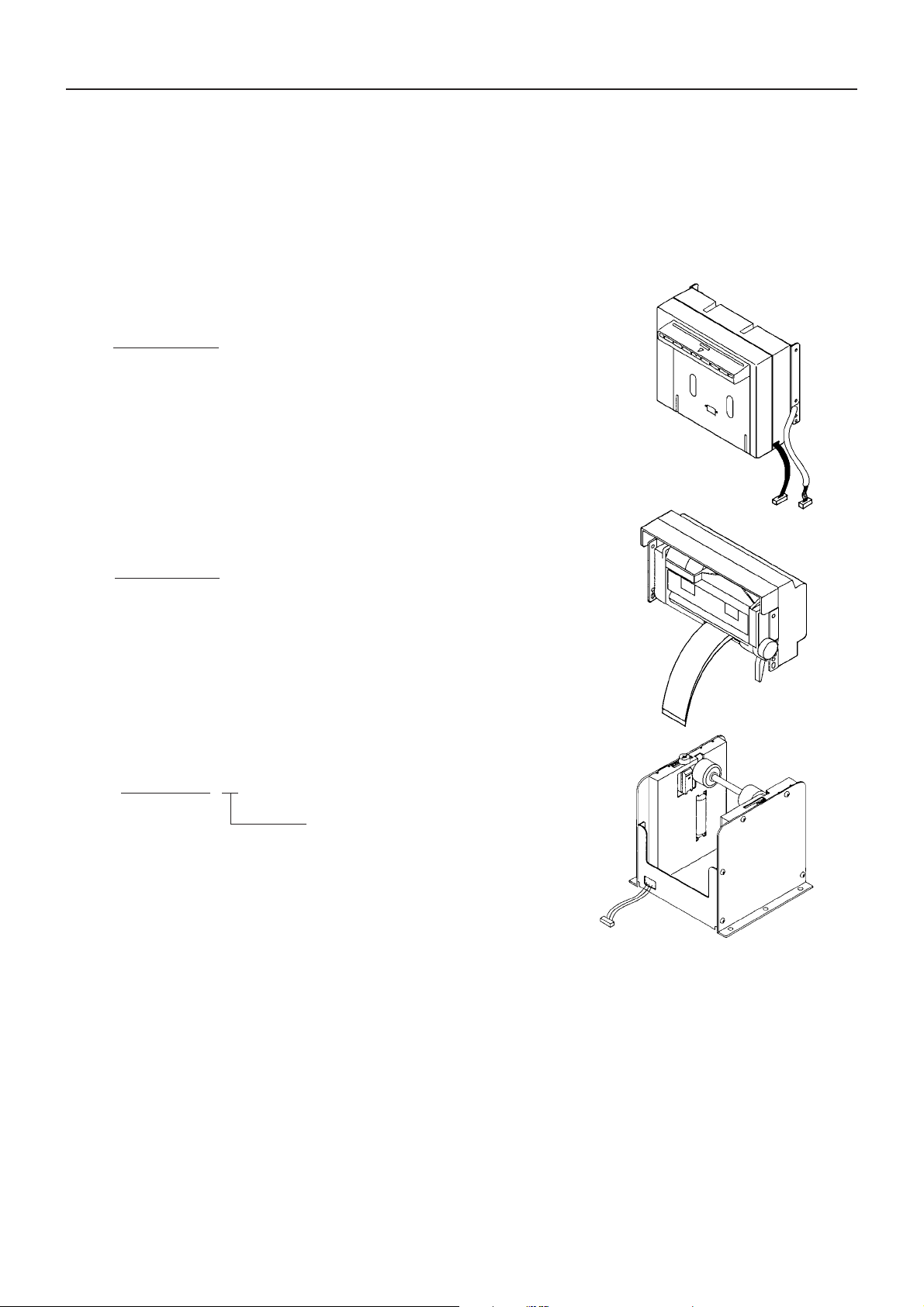
2.1.1 PRU Series (Presenter Unit)
PRU-130
<Composition>
•Paper transport section
•Auto-cutter
•Paper sensor
•Attaching bracket
2.1.2 PMU Series (Printer Mechanism Unit)
PRU·PMU·PHU SERIES SPECIFICATIONS
PMU-231
<Composition>
•Printer mechanism
•Paper guide
•Attaching bracket
2.1.3 PHU Series (Paper Holding Unit)
PHU-13 1
PNE sensor
1 : 1 piece
2 : 2 pieces
3

2.2 Specifications Lists
2.2.1 PRU Series (Presenter Unit)
(1) General Specifications
Item Content
Used Paper Type : Thermal paper
Paper width : 58 to 82.5 mm
Paper thickness : 60 to 85 µm
Presenter
Auto-cutter Cutting method : V-shaped blade, slide-type full cutting
(ACS-230F) Allowable cutting frequency : 20 cuts/min
Drive voltage DC 24 V ±10% (Motor)
Reliability Presenter life: 30 km or over
Use environment Operation : 5 to 40 C°; 35 to 85 % RH (no condensation)
External dimensions
Weight 0.5 kg
Standard issue length : 64 to 170 mm (2.5 to 6.7 inches)
∗Refer to “2.3 Designing PRU and PMU Unit Installation’’
Issue speed : Approx. 350 mm/sec
DC 5 V ± 5% (Sensor related)
Auto cutter life : 500,000 cuts or over
Storage : – 20 to 60 C°; 10 to 90 % RH (no condensation)
Refer to “8.1 Outline Drawing for PRU-130”.
PRU·PMU·PHU SERIES SPECIFICATIONS
When used in combination with the PMU-231
(2) Paper issue length
64 to 170 mm (2.5 to 6.7 inches)
•When used in combination with the printer mechanism unit PMU-231.
•The length of paper longer than 170 mm is pushed out of the paper output slot.
• Refer to “2.3 Designing PRU and PMU Unit Installation” and “4. FLOW CHART” and
“5. TIMING CHART”.
(3) Motor
When voltage is applied to the motor, the paper is transported. Referring to “4. FLOW CHART”
and “5. TIMING CHART”, perform motor control.
Type : DC brush motor
Drive voltage : DC 24 V ± 10 %
Current : Max. starting current : 140 mA (DC 24 V, 25 C°)
Ave. starting current : 60 mA (DC 24 V, 25 C°)
4
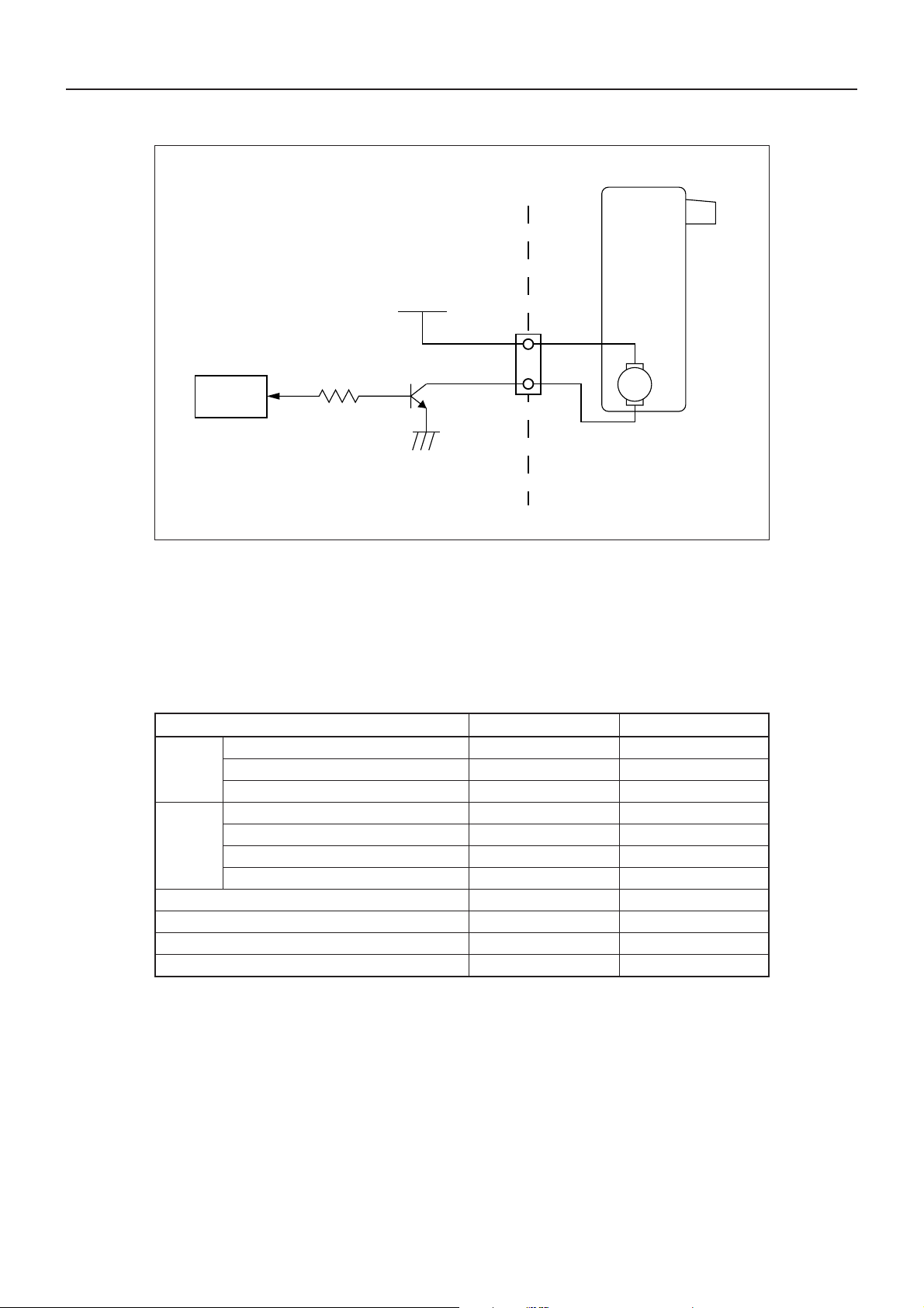
• Recommended circuit diagram
Vdd (+24 V)
PRU·PMU·PHU SERIES SPECIFICATIONS
+24V
4
1KΩ
2SC4671
CPU
GND
* 2SC4671 is a Darlington transistor with a built-in Zener diode.
* For pin numbers, refer to “ 3. 1 Connection Terminals”.
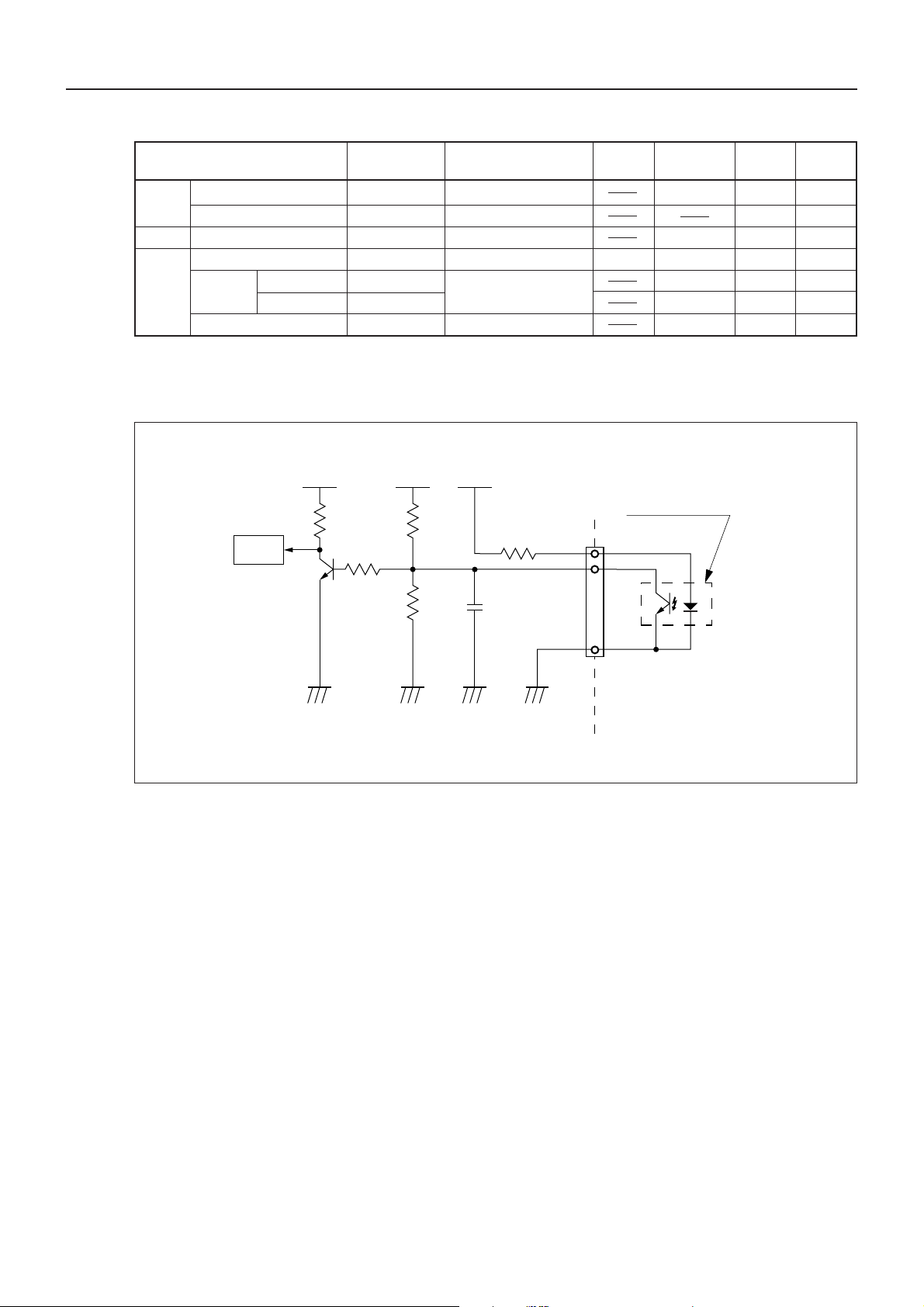
(4) Paper sensor
• Type : Reflective-type photo-interrupter
• Product No. : GP2S24 (SHARP)
• Absolute max. rating : (25 C°)
Item Symbol Rated value
Forward current IF 50 mA
Input Reverse current VR 6 V
Allowable loss P 75 mW
Collector-emitter voltage VCEO 35 V
Output
Soldering temperature (within 5 sec) Tsol 260 C°
Emitter-collector voltage VECO 6 V
Collector current I
Collector loss PC 75 mW
Total allowable loss Ptot 100 mA
Operating temperature T
Storage temperature Tstg – 40 to +100 C°
5
C
opr
M
20 mA
– 20 to +85 C°
5
• Photoelectric characteristics
PRU·PMU·PHU SERIES SPECIFICATIONS
Min. Standard Max.
value value value
Input
Item Symbol Condition
Forward voltage V
F
IF=20 mA 1.2 1.4 V
Reverse current IR VR=6 V 10 µA
Output Dark current I CEO VCE=20 V 10
Transfer
characteristics
Photocurrent I
Response Upper limit tr
time Lower limit tf
Leakage current I
C
LEAK
IF=4 mA, VCE=2 V
VCE=2 V, I C=100 µA
RL=1 kΩ, d=1 mm
IF =4 mA, V
CE
=2 V
20 45 120 µA
• Recommended circuit diagram
VddVddVdd
Paper sensor
(Photo-interrupter)
Anode
Collector
CPU
3.3KΩ
100Ω
33KΩ
180Ω
1
2
Unit
–9
10
–7
A
20 100 µs
20 100 µs
0.1 µA
33KΩ
GND GND GND GND
User side Presenter side
0.01µF
Cathode
3
* For pin numbers, refer to “ 3. 1 Connection Terminals”.
(5) Auto Cutter
For recommend circuit and seguence diagrams, refer to the separate “ACS 230 Specifications”.
6
PRU·PMU·PHU SERIES SPECIFICATIONS
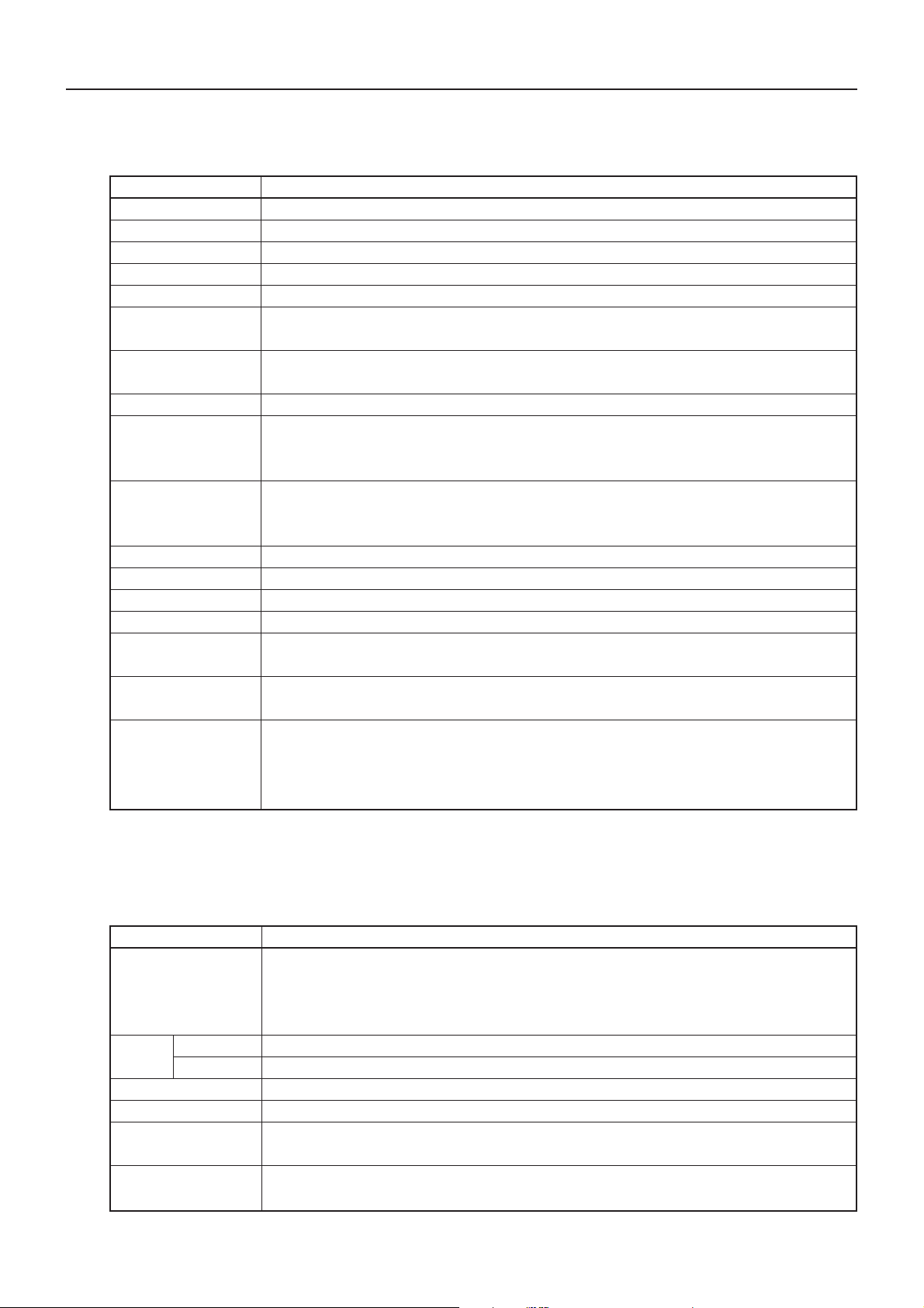
2.2.2 PMU Series (Printer Mechanism Unit)
<General Specifications>
Item Content
Print mechanism LT-380V Bottom paper insertion
Print method Line thermal dot printing
Print width 72 mm/576 dots
Dot density 8 dots/mm (horizontal and vertical)
Print speed 62.5 mm/s (at max. speed), (500 dot lines/s)
Print column and 48 columns (12 × 24 font A) 1.25 × 3.00 mm
character size 64 columns (9 × 24 font B) 0.88 × 3.00 mm
Line spacing 4.23 mm (1/6 inches)
Selectable with commands (1/203 inches min.)
Types of bar code UPC-A, JAN (EAN) : 13 col./8 col., ITF, CODE39, CODE128, CODABAR
Used Paper Thermal paper roll : Width 80 mm
Paper thickness : 60 to 85 µm
Recommended paper : TF-50KS-E, E2C (Nippon Paper)
Sensor Auto Loading detection
Black mark detection (optional)
Head temperature detection, Head-up detection
Supply voltage DC 24 V ± 7 %
Power consumption 100 W
Weight 0.3 kg
External dimensions Refer to “8.2 Outline Drawing for PMU-231”.
Operating temperature 5 to 40 °C; 35 to 85 % RH (no condensation)
and relative humidity
Storage temperature –20 to 60 °C; 10 to 90 % RH (no condensation)
and relative humidity
Reliability Print head service life
Pulse resistance : 50 million pulses or over (print coverage 12.5 %)
Wear resistance : 30 km or over (at normal temperature and humidity with recommended
thermal paper)
* For details, refer to the specifications for the LT-380/381 Thermal Printers.
2.2.3 PHU Series (Paper Holding Unit)
<General Specifications>
Item Content
Paper Paper rolls Width 80 mm
Outside diameter ø 203 mm or less
Inside diameter ø 25.4 mm
Paper thickness 60 to 85 µm
Sensor PHU-131 PaperNearend sensor 1-level (adjustable)
PHU-132 PaperNearend sensor 2-level (adjustable)
Weight 0.9 kg (with paper roll excluded)
External dimensions Refer to “8.3 Outline Drawing for PHU-131/132”.
Operating temperature 5 to 40 °C; 35 to 85 % RH (no condensation)
and humidity
Storage temperature –20 to 60 °C; 10 to 90 % RH (no condensation)
and humidity
7

PRU·PMU·PHU SERIES SPECIFICATIONS
2.3 Designing PRU and PMU Unit Installation
Install the PRU and PMU units by referring to the following dimensions.
28.5
0
0
12°
52
37.5
50
Papen Sensor detection
position
When paper is longer
than 170 mm
Detection position
of the auto loading Sensor
81.4
8

PRU·PMU·PHU SERIES SPECIFICATIONS
CAUTION:
•As mounting holes for the PRU and PMU units, ø 2.7 mm burred holes are provided. So, when
mounting them, use M3 tapping screws.
•Exercise good care so that no unnecessary load is applied to the equipment and cables.
•Make sure that there are no obstructing objects when opening/closing the PRU front door.
•Avoid installing the equipment in a hot and/or humid place.
•Avoid installing the equipment in a dusty place or where it is subjected to vibrations.
9

3. CONNECTION TERMINALS
3.1 Connection Terminals
3.1.1 Presenter’s Connection Terminals
(1) Connectors Used and their purposes
Function No. of pins Type Recommended mating connector
Drive motor
Paper sensor 51004-0500 53015-0510
(2) Pin layout
Terminal No. Terminal name Function
1 Light-emitting diode Anode
2 Photo-transistor Collector Paper sensor
3 Photo-transistor Emitter
4A
5A
5
Molex 53014-0510
PRU·PMU·PHU SERIES SPECIFICATIONS
Molex
53025-0510
Presenter drive motor
(3) Circuit Diagram
Terminals No
1
2
3
4
5
(4) Terminal layout and color
Brown
Red
Orange
M
Yellow
Green
Paper
sensor
Presenter
drive motor
12345
10

3.1.2 Auto-Cutter’s Connection Terminals
(1) Connectors Used and their purposes
Function No. of pins Type Recommended mating connector
Cutter drive motor
Switch
(2) Pin layout
Terminal No. Wire color Function
1 Red Motor (+)
2 Black Motor (–)
3 Gray Switch
4 Gray Switch
4
Molex
5264-04
PRU·PMU·PHU SERIES SPECIFICATIONS
Molex
5267
5268
(3) Terminal layout and color
Black
Red
Gray
Gray
1234
11
PRU·PMU·PHU SERIES SPECIFICATIONS
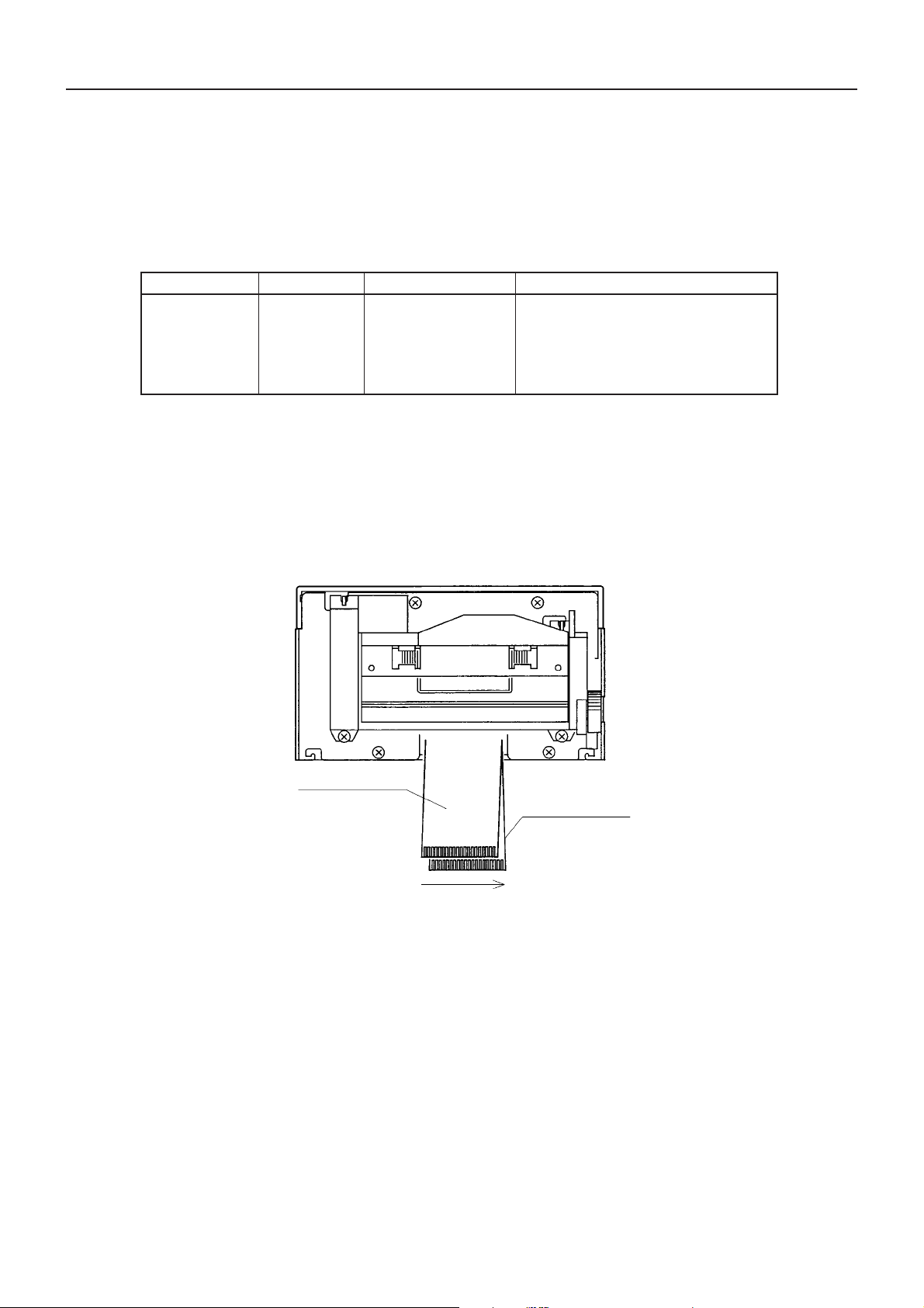
3.2 PMU Connection Terminals
The connection terminals are comprised of two flexible flat cables (FFC), the details of which are
shown below.
(1) Cable Connectors used and their purposes
Function No. of pins Type Recommended mating connector
•Motor
•Paper sensor FFC
•Head-up sensor
20
(Pitch = 1.25 mm)
•Thermal head
(2) Arrangement of FCC cable terminals
The arrangement of the FFC terminals and the functions of their terminal pins are as shown
below.
Molex
5597-20APB
5597-20CPB
FFC B
FFC A
120
12

(3) The functions of the FFC terminals pins
<FFC A>
Terminal
No.
1 STRB 3 Strobe 3
2 STRB 2 Strobe 2
3 STRB 2 Strobe 2
4 STRB 2 Strobe 2
5 STRB 1 Strobe 1
6 STRB 1 Strobe 1
7 STRB 1 Strobe 1
8 V cc Thermal head driver power supply
9 TH Thermistor
10 GND GND
11 CP Clock signal for data transfer
12 DO Print data serial output
13 PR For identification of heating element resistance
14 GND GND
15 GND GND
16 GND GND
17 GND GND
18 COM Thermal head common
19 COM Thermal head common
20 COM Thermal head common
Signal name Function
PRU·PMU·PHU SERIES SPECIFICATIONS
13

<FFC B>
Terminal
No.
1A
2B
3
4B
5
6
7
8
9
10
11 COM Thermal head common
12 COM Thermal head common
13 COM Thermal head common
14 GND GND
15 GND GND
16 GND GND
17 LATCH Print data latch signal
18 DI Print data serial input
19 STRB 3 Strobe 3
20 STRB 3 Strobe 3
Signal name Function
Paper feed motor
A
Photo-transistor
collector
Photo-transistor
emitter
Light-emitting diode
anode
Light-emitting diode
cathode
Head-up sensor
output
Head-up sensor
output
Paper sensor
Head-up sensor
PRU·PMU·PHU SERIES SPECIFICATIONS
14

4. FLOW CHART
4.1 PRU Unit Initialization at Power On
Power On
Hardware initialization
PRU·PMU·PHU SERIES SPECIFICATIONS
Auto-cutter (ACS-230F)
initialization
Paper-out in
printermechanism?
Waiting for Alarm to be
reset.
Auto-loading
performed already?
No
* For the ACS-230 initialization sequence and
drive sequence, refer to the separate
“Specifications for the ACS-230”.
No
Yes
I
Presenter initialization
Presenter initialization
On-line standby state
15

I
Paper feed of 20 lines
(Approx. 85 mm)
PRU·PMU·PHU SERIES SPECIFICATIONS
Auto-cutter (ACS-230F)
initialization
Full cutting
(Auto-cutter is driven.)
Presenter motor is driven
(1.5 sec)
Paper outputted from
paper exit slot?
Yes
Complete
* For the ACS-230 initialization sequence and
drive sequence, refer to the separate
“Specifications for the ACS-230”.
No
16

PRU·PMU·PHU SERIES SPECIFICATIONS
4.2 Printing (Issuing Receipts)
The following sequence takes place when one of various print commands, such as print command
(OAh), print and line feed command (ODh), print and minimal-pitch paper feed command (ESC J),
and print and n-line paper feed command (ESC d), is executed.
Printing
(Issuing receipt)
Print and paper feed
Presenter is driven
Print and paper
feed complete?
Yes
Complete
No
17

PRU·PMU·PHU SERIES SPECIFICATIONS
4.3 Outputting Printed Paper
The following sequence takes place in synchronism with the driving of the auto-cutter.
Cutter driving
No
Amount of paper feed
less than 63 mm?
Yes
Paper feed of difference
of 63 mm performed.
Full cutting (Auto cutter is
driven.)
Presenter is driven.
1.5 second timer is
started.
1.5 second timer
timed out?
* While feeding this difference of paper (blank
feed), if a paper-out condition occurs, the
auto-cutter is not driven, and the equipment
goes into a “wait-alarm-reset” state.
* For the ACS-230 initialization sequence and
drive sequence, refer to the separate
“Specifications for the ACS-230”.
No
Yes
Presenter is turned off.
Paper outputted
from paper exit slot?
Yes
Complete
18
No

1.5 sec
PRU·PMU·PHU SERIES SPECIFICATIONS
ON
OFF
ON
OFF
ON
OFF
ON
OFF
Approx. 200ms
1ms
ON
OFF
5. TIMING CHART
5.1 PRU Timing Chart
Motor Drive Signal
Printer
Motor Drive Signal
Presenter
19
Motor Drive Signal
Auto Cutter
Motor Brake Signal
Cutter Sensor Signal

1.5 sec
PRU·PMU·PHU SERIES SPECIFICATIONS
ON
OFF
ON
OFF
HIGH
LOW
ON
OFF
ON
OFF
Approx. 200ms
1ms
ON
OFF
Motor Drive Signal
Printer
(Controlled by paper sensor)
5.2 PPU Timing Chart
Motor Drive Signal
Presenter
Paper Sensor
20
Motor Drive Signal
Auto Cutter
Motor Drive Signal
Cutter Sensor Signal

PRU·PMU·PHU SERIES SPECIFICATIONS
6. DESIGN CONSIDERATIONS
(1) As mounting holes for the PRU and PMU units, ø 2.7 mm burred holes are provided. So, when
mounting them, use M3 tapping screws.
(2) Refer to Sec. 2.3 for Designing PRU and PMU Unit Installation.
(3) Exercise good care so that no unnecessary load is applied to the equipment and cables.
(4) Make sure that there are no obstructing objects when opening/closing the PRU front door.
(5) Avoid installing the equipment in a hot and/or humid place.
(6) Avoid installing the equipment in a dusty place or where it is subjected to vibrations.
21

7. OPERATION
7.1 PRU (Presenter Unit)
7.1.1 Clearing Jams in the Presenter
Turn OFF the power.
1
Open the front door.
2
While rotating the roller with your hand, remove any paper
3
from the inside completely.
Use a pair of tweezers to remove any paper jamming
4
PRU·PMU·PHU SERIES SPECIFICATIONS
Close the front door.
5
CAUTION:
•Do not try to rotate the roller forcibly or apply excessive force. This may damage the equipment.
22

7.1.2 Releasing a Locked Cutter
Referring to “7.1.1 Clearing Jams in the Presenter”, remove
1
any paper in the paper path.
Turn ON the power. The auto-cutter initializes itself, and the
2
blade is returned.
If the blade is not returned by the operation in step 2, turn
3
OFF the power, and rotate the auto-cutter emergency knob in
the direction of the arrow to have the auto-cutter blade
returned.
PRU·PMU·PHU SERIES SPECIFICATIONS
Using a pair of tweezers, remove any paper remaining on and
4
around the auto-cutter blade.
Emergency knob
23

7.2 PMU (Printer Mechanism Unit)
7.2.1 Loading Printing Paper
PRU·PMU·PHU SERIES SPECIFICATIONS
Cut the edge of the paper roll approximately at a
1
right angle and straight.
Check the winding direction of the paper roll, and
2
then insert the paper roller into the paper roll.
Install the paper roller (on which the paper roll was
3
set) in the paper holder.
Make sure that the printer is turned ON.
4
Paper winding
direction
Good Good Good
No good No good No good
24
Paper roller

If residual paper is still remaining inside after a
5
paper-out condition, remove it by referring to “7.2.2
Removing Residual Paper”.
Raise the head-up lever of the printer mechanism.
6
Insert the end of the paper roll straight into the
7
paper insertion slot up until the paper comes to a
stop.
Lower the head-up lever, and the printer is now
8
ready to print.
PRU·PMU·PHU SERIES SPECIFICATIONS
Up
Head-up lever
Down
CAUTION:
•Always use the specified types of paper rolls.
• Use of paper other than specified may not guarantee print quality, head service life, presenter
functions, etc.
• Do not insert paper into the presenter with its end fluffed or folded over. Otherwise, paper jams or
improper paper insertion may result.
• If there is a slack in the paper, wind the paper roll back slightly to remove the slack.
• If the paper is set inclined, raise the head-up lever to correct, or pull the paper out once and then
reinsert it.
• Do not hold or push on the paper while in printing. This may cause a paper jam.
25

7.2.2 Removing Residual Paper
Raise the head-up lever.
1
PRU·PMU·PHU SERIES SPECIFICATIONS
Pull the paper out slowly. The head moves away
2
from the platen roller, allowing the paper to be
pulled out.
Knob
Head-up lever
CAUTION:
•Never pull out the paper with the head-up lever left lowered. This may damage the head.
• Some mechanical parts of the printer may become HOT. Be extremely careful to do any printer
related work immediately after printing.
26

7.2.3 Clearing Paper Jams
Turn the OFF power.
1
Cut apart the paper at a point near the paper insertion
2
slot.
Move the knobs on both sides in the direction of the
3
arrow to separate the printer mechanism and the autocutter.
Raise the head-up lever to move the head away from
4
the platen roller.
PRU·PMU·PHU SERIES SPECIFICATIONS
Rotate the printer mechanism knob and remove any
5
paper remaining in the paper path completely.
Lower the head-up lever, and return the printer
6
mechanism to its original position.
Knob
CAUTION:
•The head area is HOT . Avoid any printer-related work immediately after printing.
• While removing residual paper, be careful not to touch the heated surface of the head with a bare
hand or any metal object.
27

7.3 PHU (Paper Holding Unit)
7.3.1 Loading a Paper Roll
Check the winding direction of the paper roll, and then insert the paper roller
1
into the paper roll.
Install the paper roller (on which paper roll was set) in the paper holder.
2
Paper winding
direction
PRU·PMU·PHU SERIES SPECIFICATIONS
Paper roller
28

7.3.2 Paper-Near-End Sensor Function
When the paper supply becomes low, the PNE (Paper-Near-
1
End) sensor outputs a signal, informing the host of this fact,
and printing can be stopped.
The PNE sensor can be adjusted by loosening the screw on its
2
top to allow up to 50-mm paper roll diameter.
PRU·PMU·PHU SERIES SPECIFICATIONS
29

8. OUTLINE DRAWINGS
8.1 Outline Drawing for PRU-130
(Paper roll width)
0
-0.5
80
67(Paper roll center)
PRU·PMU·PHU SERIES SPECIFICATIONS
90.8
21.6
Note 1)
4– ø 2.7
(Burred)
97.5
Paper
insertion
slot
57.2
46.2
6.5
52
74.6
Note 1): Use M3 tapping screws.
14.5
Paper exit slot
4.5
9
7.2
67
121.5
Presenter harness
Auto-cutter
harness
160
Unit : mm
250
30

8.2 Outline Drawing for PMU-231
80
PRU·PMU·PHU SERIES SPECIFICATIONS
Note 1)
37.55.25
4
4 – ø 2.7
(Burred)
26.5
1.5
121.3
33.23
49.23
66
68.5
21
2 – ø 3
(Slots)
160
Flat cables
Note 1): Use M3 tapping screws.
Unit : mm
31

8.3 Outline Drawing for PHU-131/132
6 – ø 5
132.2
122.2
250
PNE harness
5
48 48
12
ø 203.2
(Max. paper roll dia.)
PRU·PMU·PHU SERIES SPECIFICATIONS
120
125.2
1.6
Unit : mm
32
 Loading...