

Command Reference
LINE THERMAL PRINTER
MODEL
Rev. 1.01 Newly issued on December 19, 2002
PPU-231II
REVISION
Rev.No. Date Comment
Rev. 1.00 Jun. 10, 2002 Newly issued
Rev. 1.01 Dec. 19, 2002 Revised P. 12, P. 78, P. 79, P. 90
1. PRINT CONTROL FUNCTIONS
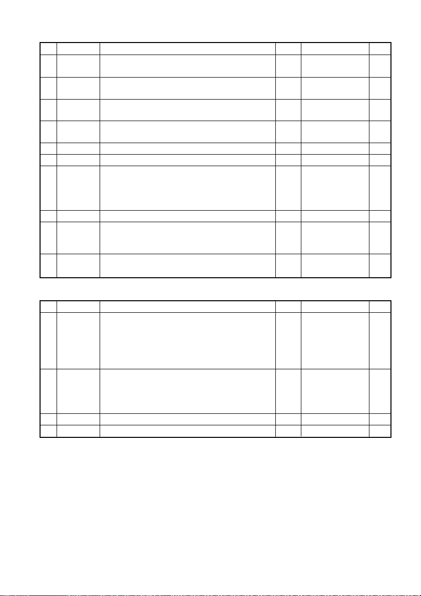
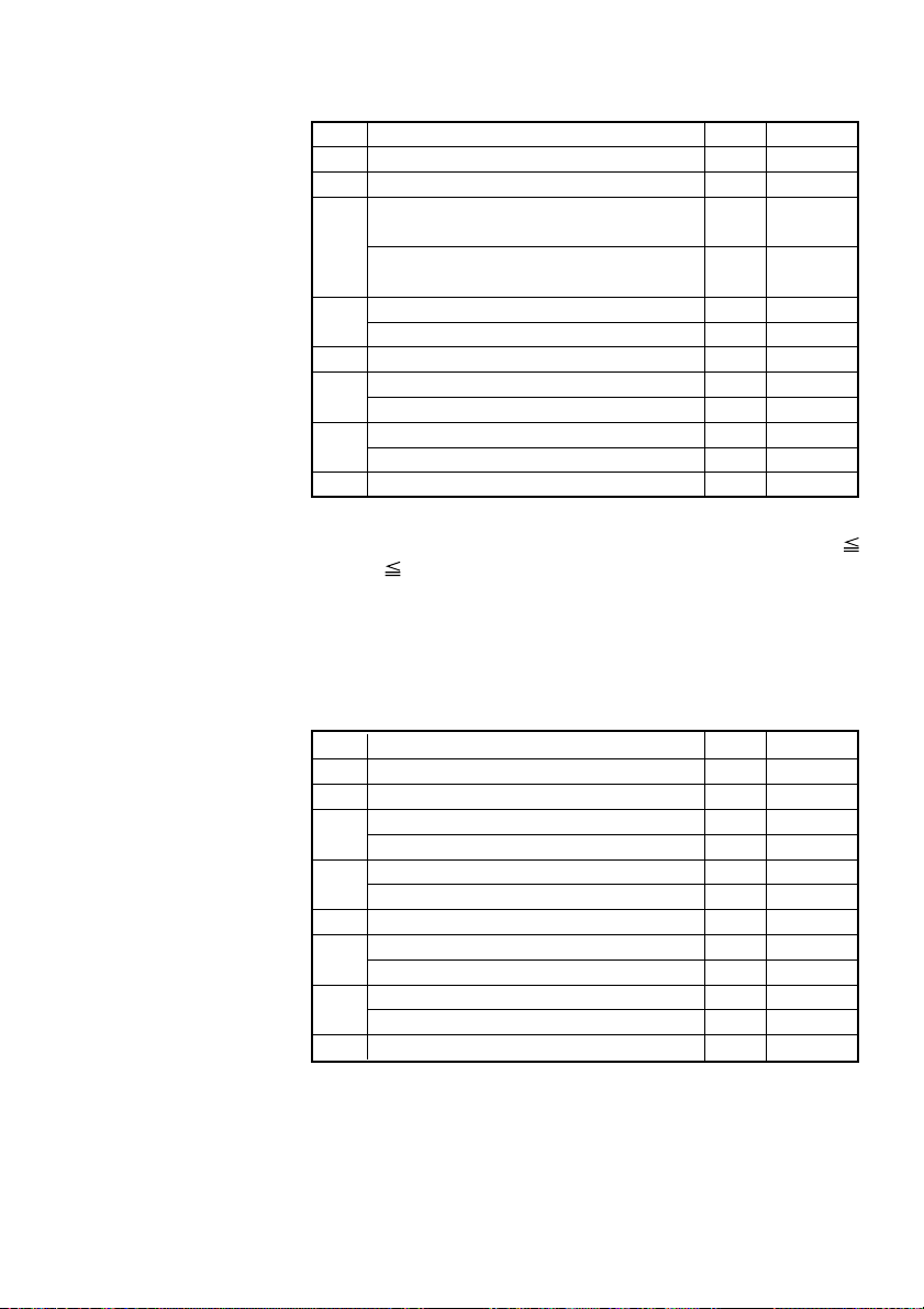
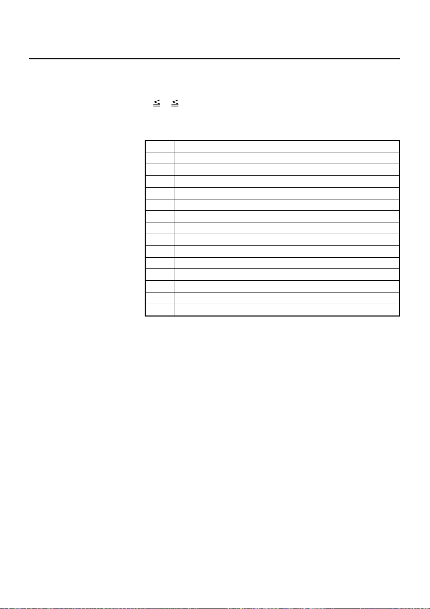
1.1 Command List
No.
Command
1 HT Horizontal tab S.P.
2 LF Printing and paper feed S.P.
3 CR Back to printing S.P.
Printing in PAGE MODE and returning to
4FF
5 CAN Canceling print data in PAGE MODE P
6 DLE EOT Sending status in real-time S.P.
7 DLE ENQ Real-time request to printer S.P.
8 ESC FF Printing data in PAGE MODE P
9
10 ESC SP Setting the right spacing of the character S.P.*
11 ESC ! Collectively specifying the printing mode S.P.
12 ESC $ Specifying the absolute positions S.P.
13 ESC %
14 ESC & Defining the download characters S.P.
15 ESC
16 ESC - Specifying/Canceling underline S.P.
17 ESC 2 Specifying 1/6-inch line feed rate S.P.
18 ESC 3 Setting line feed rate of minimum pitch S.P.*
19 ESC = Data input control S.P.
20 ESC ? Deleting download characters S.P.
21 ESC @ Initializing the printer S.P.
22 ESC D Setting horizontal tab position S.P.
23 ESC E Specifying/Canceling Emphasis Printing S.P.
24 ESC G
25 ESC J
26 ESC L Selecting PAGE MODE S
27 ESC M Selection of character fonts S.P.
28 ESC R Selecting the international character set S.P.
29 ESC S Selecting STANDARD MODE P
30 ESC T
STANDARD MODE
Printing and paper feeding to the top of
the Black mark position
Specifying/Canceling download character set
Specifying the bit image mode S.P.
*
Specifying/Canceling Double strike printing
Printing and feeding paper in minimum pitch
Selecting the character printing direction
in PAGE MODE
Function Mode Code Page
<09>H
<0A>H
<0D>H
P
<0C>H
S
<18>H
<10>H<04>H<n>
<10>H<05>H<n>
<1B>H<0C>H
<1B>H<20>H<n>
<1B>H<21>H<n>
*
<1B>H<24>H<n1>
<n2>
S.P. <1B>H<25>H<n>
<1B>H<26>H<s>H
<n><m>[<a><p1>
<p2> ⋅ ⋅ <ps×a>]
m-n+1
<1B>H<2A>H<m>
<n1><n2>[<d>]k
<1B>H<2D>H<n>
<1B>H<32>H
<1B>H<33>H<n>
<1B>H<3D>H<n>
<1B>H<3F>H<n>
<1B>H<40>H
<1B>H<44>H [<n>]k<00>
<1B>H<45>H<n>
S.P.
<1B>H<47>H<n>
S.P.*
<1B>H<4A>H<n>
<1B>H<4C>H
<1B>H<4D>H<n>
<1B>H<52>H<n>
<1B>H<53>H
<1B>H<54>H<n>
P
— 1 —
5
6
7
8
9
10
13
14
15
17
19
21
22
24
26
27
28
29
30
31
32
33
34
35
36
37
38
39
40
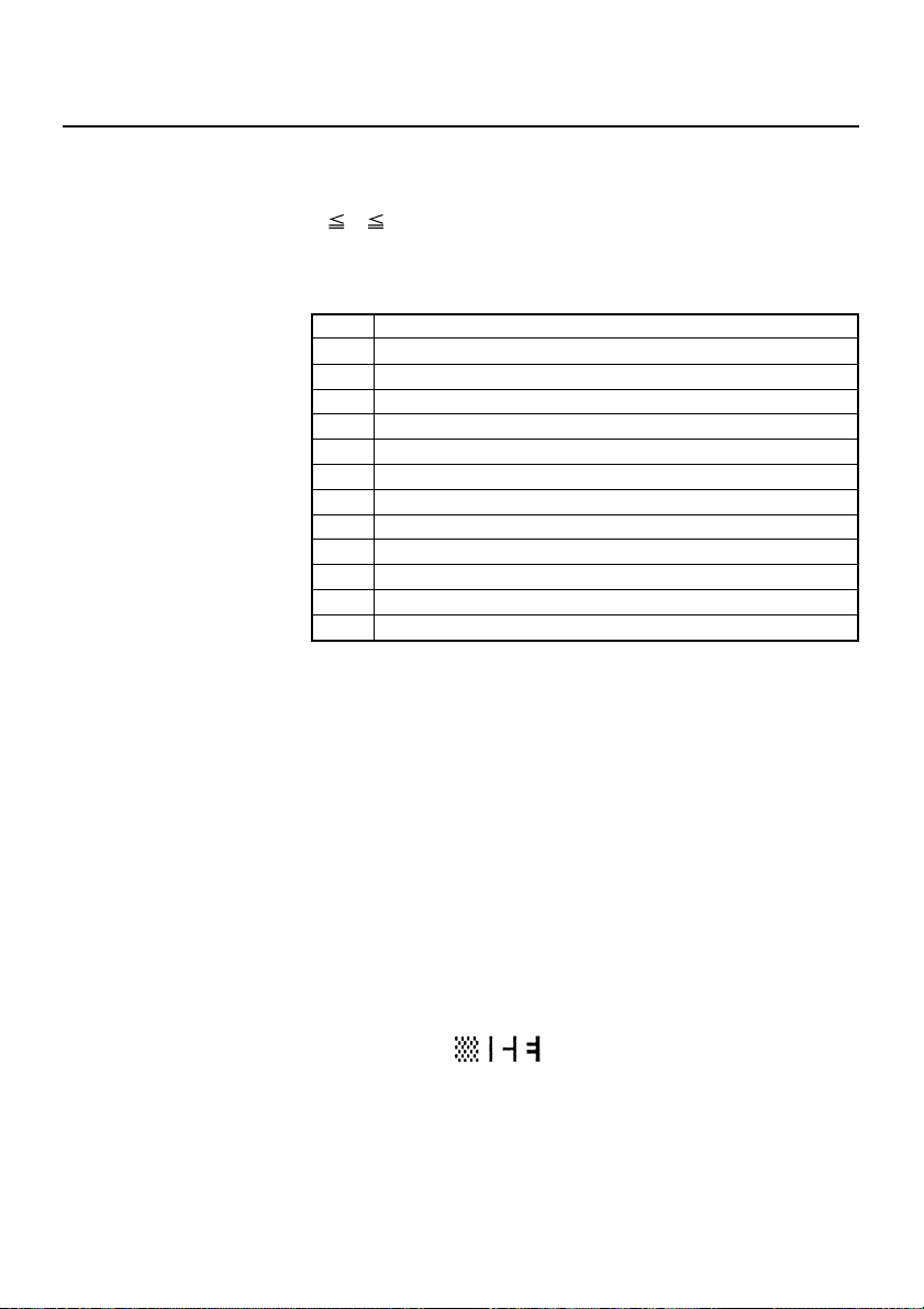
No.
Command
31 ESC V
32 ESC W Defining the print area in PAGE MODE P*
33 ESC \ Specifying the relative position S.P.*
34 ESC a Aligning the characters S.P.
35 ESC c3
36 ESC c4
37 ESC c5 Enabling/Disabling the panel switches S.P.
38 ESC d
39 ESC n
40 ESC t Selecting the character code table S.P.
41 ESC {
42 GS ! Specifying the character size S.P.
43 GS $
44 GS
45 GS ( A Execution of test printing S
46 GS / Printing the downloaded bit image S.P.
47 GS : Starting/Ending macro definition S.P.
48 GS A
49 GS B
50 GS H
51 GS I Sending the printer ID S.P.
52 GS L Setting the left margin S
53 GS P Specifying the basic calculation pitch S.P.
54 GS R0 Collecting receipts S.P.
55 GS R1 Setting receipt collection timer S.P.
56 GS S Detecting a black mark S.P.
In the Mode column: S = STANDARD MODE, P = PAGE MODE
Specifying/Canceling 90°-right-turned
characters
Selecting the Paper Sensor valid for
paper end signal output
Selecting the Paper Near-end Sensor valid
for print stop
Printing and feeding the paper by “n” lines
Setting a remaining amount of printout
Specifying/Canceling the inverted characters
Specifying the absolute vertical position
of characters in PAGE MODE
Defining the download bit image S.P.
*
Correcting the position of black mark
top position
Specifying/Canceling the black/white
inverted printing
Selecting of printing position of HRI
characters
Function Mode Code Page
S.P.
S.P.
S.P.
S.P.
P
S.P.
S.P.
S.P.
* shows the command affected by GS P.
57 GS V Cutting the paper S.P.*
S
<1B>H<56>H<n>
<1B>H<57>H<xL><xH>
<yL><yH><dxL><dxH>
<dyL><dyH>
<1B>H<5C>H<nL><nH>
<1B>H<61>H<n>
<1B>H<63>H<33>H
<n>
<1B>H<63>H<34>H
<n>
<1B>H<63>H<35>H
<n>
<1B>H<64>H<n>
<1B>H<6E>H<n>
<1B>H<74>H<n>
S
<1B>H<7B>H<n>
<1D>H<21>H<n>
<1D>H<24>H<nL>
*
<nH>
<1D>H<2A>H<n1>
<n2>[<d>]n1×n2×8
<1D>H<28>H<41>H
<pL><pH><n><m>
<1D>H<2F>H<m>
<1D>H<3A>H
<1D>H<41>H<m>
<n>
<1D>H<42>H<n>
<1D>H<48>H<n>
<1D>H<49>H<n>
<1D>H<4C>H<nL>
*
<nH>
<1D>H<50>H<x>
<y>
<1D>H<53>H<30>
H<n>H
<1D>H<53>H<31>
H<n>
<1D>H<53>H
(
1)<1D>H<56>H<m>
(2)<1D>H<56>H<m>
<n>
41
42
44
45
46
47
48
49
50
51
52
53
55
56
58
59
60
61
62
63
65
66
68
69
70
71
72
— 2 —
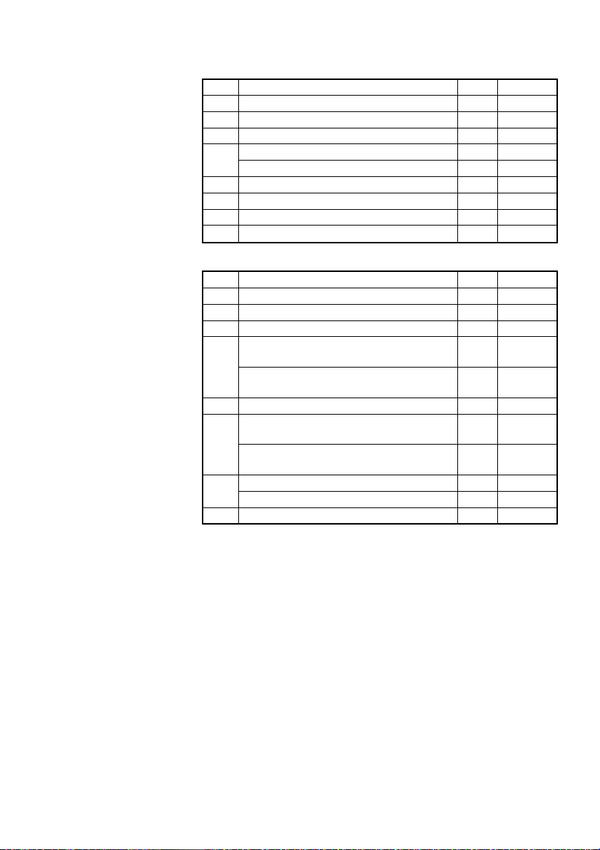
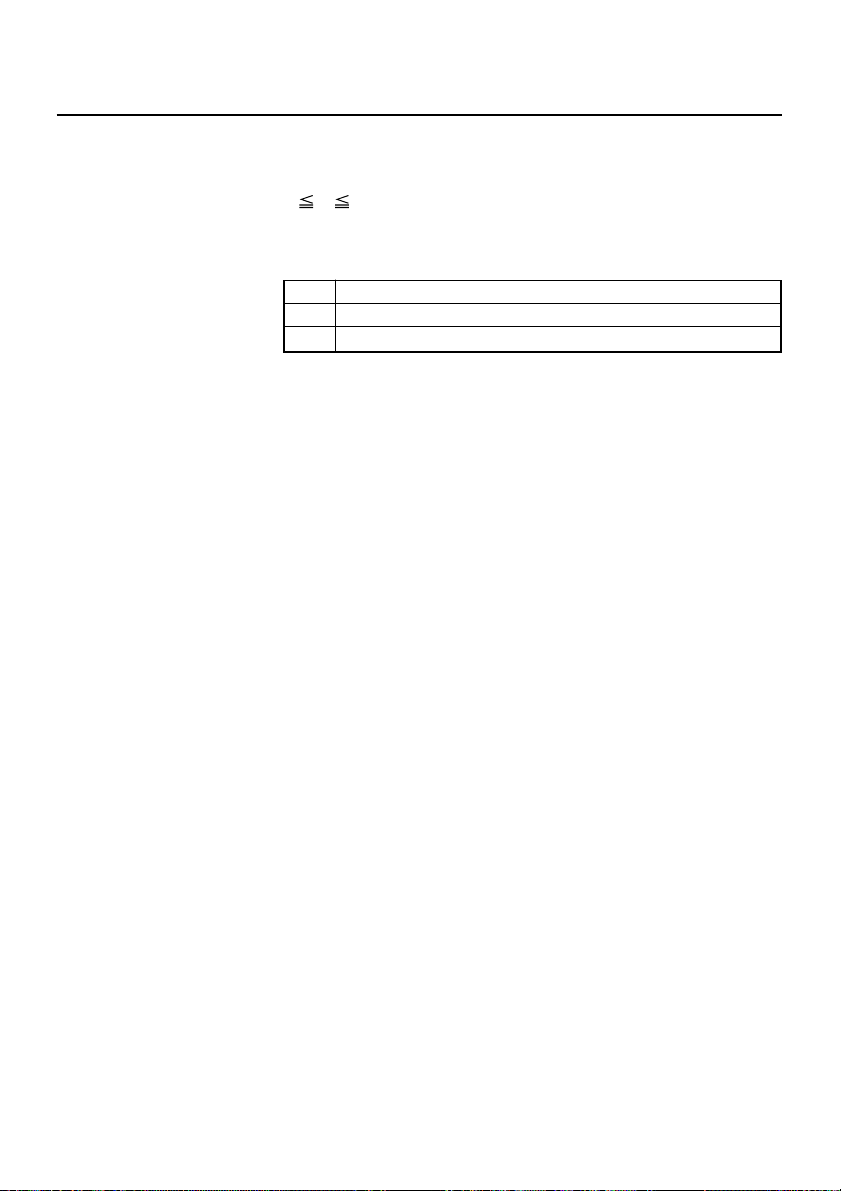
No.
Command
58 GS W Setting the print area width S.P.*
59 GS \
60 GS ^ Executing the macro S.P.
61 GS a
62 GS f Selecting the font of HRI characters S.P.
63 GS h Specifying the height of the bar code S.P.
64 GS k Printing the bar code S.P.
65 GS r Sending status S.P.
66 GS v0
67 GS w
Specifying the relative vertical position
of a character in PAGE MODE
Enabling/Disabling ASB (Automatic
Status Back)
Printing of raster bit image S
Specifying the horizontal size
(magnification) of bar code
Function Mode Code Page
S.P.*
S.P.
S.P.
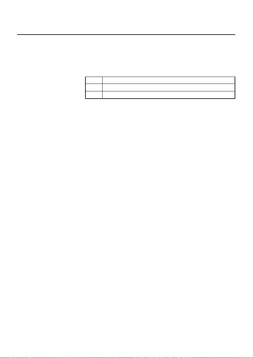
Command relative to NV memory
No.
Command
68 FS g3
69 FS g4
70 FS p Printing the download NV bit images S
71 FS q Defining the download NV bit image S
Writing data into the download user NV memory
Reading data from the download user NV memory
Function Mode Code Page
S.P.
<1D>H<57>H<nL>
<nH>
<1D>H<5C>H<nL>
<nH>
<1D>H<5E>H<n1>
<n2><n3>
<1D>H<61>H<n>
<1D>H<66>H<n>
<1D>H<68>H<n>
(1)<1D>H<6B>H<m>
[d1...dk]NUL
(2)<1D>H<6B>H<m>
<n>[d1...dn]
<1D>H<72>H<n>
<1D>H<76>H<30>H
<m><xL><xH>
<yL><yH>[<d>]k
<1D>H<77>H<n>
<1C>H<67>H<33>
<m>H<a1>H<a2>H
S
<a3>H<a4>H<nL>H
<nH>H[<d>]nL+
(nH×256)
<1C>H<67>H<34>H
<m>H<a1>H<a2>H
<a3>H<a4>H<nL>H
<nH>H
<1C>H<70>H<n><m>
<1C>H<71>H<n>H
73
75
76
77
80
81
82
90
91
93
94
96
98
100
In the Mode column: S = STANDARD MODE, P = PAGE MODE
* shows the command affected by GS P.
Commands Nos. 48 and 56 are available only if the Black mark feature is specified.
— 3 —

1.2 Command Details
1.2.1 Descriptions of Each Item
XXXX
[Function] The name of a command.
[Code] The string of codes comprising the command is represented
[Range] Indicates the values (setting range) of argumeuts of the
[Outline] Describes the functions of the command.
[Caution] Describes important points and cautionary notes, as required.
[Default] Initial values for the command if it has arguments.
[Reference] Describes commands related to the command when it is used.
[Sample Program] Describes examples of coding on Quick-Basic.
[Printing Result] Describes the print results obtained by executing the above
by < >H for hexadecimal numbers, < >B for binary numbers,
and < > for decimal numbers, [ ] k denotes the number of
repetition of “k” times.
command.
Note: If values outside the defined domain specified with
control codes are used, malfunctions could possibly
occur, so be sure to use the values within the defined
domain.
Examples are only for reference. They may vary depending
on language and version. For details, please refer to a manual
in your language.
programs. However, the print r esults shown are different in scale
from actual print results.
— 4 —

1.2.2 Command Details
HT
[Function] Horizontal tab
[Code] <09>H
[Outline] Shifts the printing position to the next horizontal tab position.
• Ignored when the next horizontal tab position has not been
set.
[Caution] • The horizontal tab position is set by ESC D.
• The initial setting of horizontal tab positions is at intervals of
8 characters for font A at 9th, 17th, 25th, 33rd, columns.
[See Also] ESC D
[Sample Program]
[Printing Result]
LPRINT “0123456789012345678901”;
LPRINT CHR$(&HA);
LPRINT CHR$(&H9) + “AAA”;
LPRINT CHR$(&H9) + “BBB”;
LPRINT CHR$(&HA) ;
LPRINT CHR$(&H1B) + “D”;
LPRINT CHR$(3) + CHR$(7) + CHR$(14) + CHR$(0);
LPRINT CHR$(&H9) + “AAA”;
LPRINT CHR$(&H9) + “BBB”;
LPRINT CHR$(&H9) + “CCC” + CHR$(&HA) ;
END
12345678901234567890
AAA BBB
AAA BBB CCC ← When set to the 4th, 8th, and 15th columns
← Initially set horizontal tab
— 5 —

LF
[Function] Printing and paper feed
[Code] <0A>H
[Outline] Prints data inside the print buffer and feeds paper based on the
line feed amount having been set.
[Caution] The head of the line becomes the next print starting position.
[See Also] ESC 2, ESC 3
[Sample Program]
LPRINT “AAA” + CHR$(&HA) ;
LPRINT “BBB” + CHR$(&HA) ;
LPRINT CHR$(&HA) ;
LPRINT “CCC” + CHR$(&HA) ;
END
[Print Results]
← Print and line feed
AAA
BBB ← Print and line feed
← Line feed only
CCC ← Print and line feed
— 6 —

CR
[Function] Back to printing
[Code] <0D>H
[Outline] 1) When DSW1-5 is OFF:
This command is ignored.
2) When DSW1-5 is ON:
With data held inside the internal print buffer, printing and
line feed are performed.
Without data inside the internal print buffer, however, only
line feed is performed.
[See Also] LF
[Sample Program]
[Print Results]
LPRINT “AAA” + CHR$(&HD) ;
LPRINT “BBB” + CHR$(&HD) ;
LPRINT CHR$(&HD) ;
LPRINT “CCC” + CHR$(&HD) ;
END
AAA
← Print and line feed
BBB ← Print and line feed
← Line feed only
CCC ← Print and line feed
— 7 —
FF (Page Mode)
[Function] Printing in PAGE MODE and returning to STANDARD MODE
[Code] <0C>H
[Outline] Executes a batch printout of the data mapped in the entire print
area, and then returns to STANDARD MODE.
[Caution] • All mapped data is erased after printout.
• The print area set up by ESC W is initialized.
• This command does not execute a paper cut.
• After this command is executed, the beginning of the line is
taken as the start position for the next print.
• This command is only effective when the PAGE MODE is
selected.
[See Also] ESC FF, ESC L, ESC S, GS FF
FF (Standard Mode)
[Function] Printing and paper feeding to the top of the Black mark position
[Code] <0C>H
[Outline] This command prints the data in the printer buffer and searches
for the head of the next label (Black mark position)
[Caution] This command is valid only when the label printer is selected
with DS2-7. It is ignored when the thermal paper is specified.
After sending one label worth of print data, be sure to send this
command or GS FF command. After the user intentionally
moved the label paper, this command cannnot search for the
head of the label properly.
[See Also] GS FF, GS <
[Sample Program]
LPRINT “ABC” ; CHR$ (&HA) ;
LPRINT “123” ; CHR$ (&HC) ;
LPRINT “HHHHH” ; CHR$ (&HA) ;
LPRINT “gggg” ; CHR$ (&HC) ;
END
[Print Result]
ABC
123
HHHHH
ggggg
— 8 —

CAN
[Function] Canceling print data in PAGE MODE
[Code] <18>H
[Outline] Erases all data contained in the currently effective print area in
PAGE MODE.
[Caution] • This command is only effective when PAGE MODE is selected.
• If the previously established print area overlaps the currently
effective print area, the overlapped data in the previously
established area will be erased.
[See Also] ESC L, ESC W
— 9 —
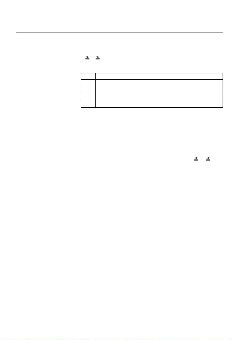
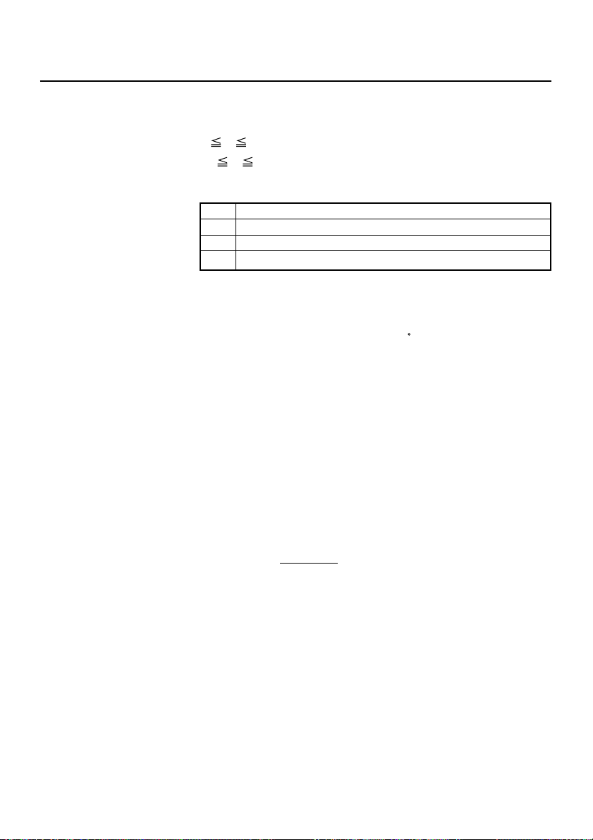
DLE EOT n
[Function] Sending status in real-time
[Code] <10>H<04>H<n>
[Range] 1
[Outline] Sends in real-time the status specified by “n”.
[Caution] • Each status represents the current status. It is 1 byte data.
n 4
n Status
1 Printer status
2 Status caused by an offline condition
3 Status caused by an error
4 Continuous paper detector status
• The status is transferred without checking whether the host is
ready to receive or busy.
• This command is executed even if the printer is in offline state,
receive-buffer full state, or error state.
• This command is dealt with when it is received.
• If another data string of <10>H<04>H<n> (1
received, the printer acts the same way as with this command.
Therefore, the user should be reminded of this fact.
[Example 1]
Suppose a command “ESC * mnL nH [d1 ... dk]”, where d1 =
<10>H, d2 = <04>H, d3 = <01>H.
• The DLE EOT n command cannot be interleaved into the code
string of another command consisting of 2 bytes or more.
[Example 2]
If the printer sends DLE EOT 3 after the host has sent up to ESC
3 in its attempt to send ESC 3 n, the printer handles the ESC 3
as ESC 3 <10>H. Thus, the user should be cautious.
• If ASB (Automatic Status Back) is enabled by GS a, it is
necessary to discriminate between the status due to ASB and
the status due to this command.
n 4) is
— 10 —
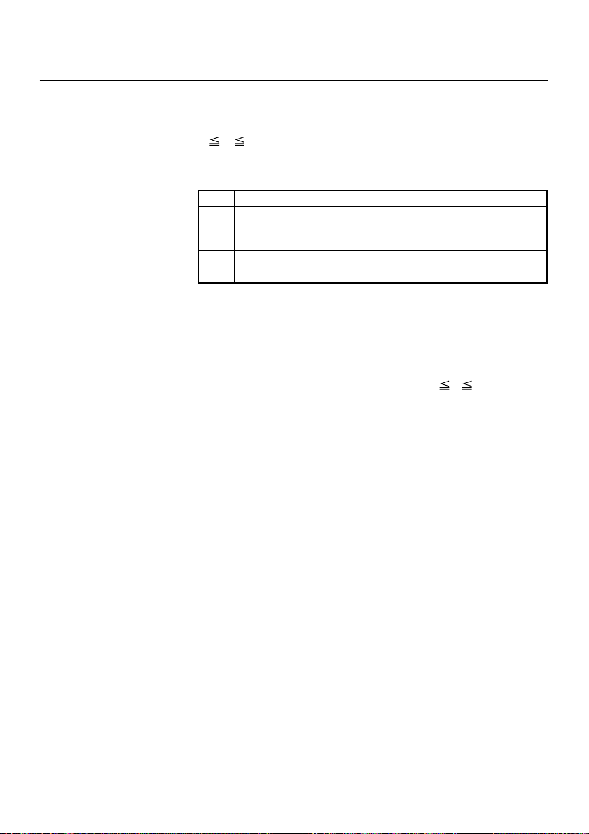
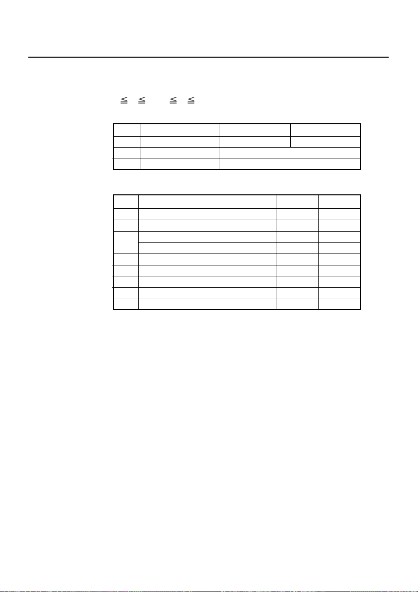
(1) Printer status (When n = 1 is specified)
Bit Status Hex. Decimal
0 Unused 00 0
1 Unused 02 2
2 Undefined — —
Online status 00 0
3
Offline status 08 8
4 Unused 10 16
5 Undefined — —
6 Undefined — —
7 Unused 00 0
(2)
Status caused by an offline condition (When n = 2 is specified)
Bit Status Hex. Decimal
0 Unused 00 0
1 Unused 02 2
2 Unused 00 0
Not in paper feed state triggered by
FEED switch
3
In paper feed state triggered by FEED
switch
4 Unused 10 16
Printing is not stopped because of
“paper out” state
5
Printing is stopped because of
“paper out” state
Error not occurred 00 0
6
Error occurred 40 64
7 Unused 00 0
00 0
08 8
00 0
20 32
Bit 5: Printing is stopped if the paper end detector detects a
“paper out” state, or if the printer is out of paper when
the Paper Near-end Sensor is enabled by ESC c 4. At this
time, bit 5 = “1”.
— 11 —
(3) Status caused by an error (when n = 3 is specified)
Bit Status Hex. Decimal
0 Unused 00 0
1 Unused 02 2
No Black mark detection error occurred
(only when “Black mark” is selected).
2
A Black mark detection error occurred
(only when “Black mark” is selected).
Auto cutter error not occurred 00 0
3
Auto cutter error occurred 08 8
4 Unused 10 16
Unrecoverable error not occurred 00 0
5
Unrecoverable error occurred 20 32
Auto recovery error not occurred 00 0
6
Auto recovery error occurred 40 64
7 Undefined 00 0
00 0
04 4
Bit 3: If this error occurred because of a paper jam, for example,
remove the cause of the error, and then DLE ENQ n (1
n 2) can be used to recover from the error. However, it
is not possible to recover from any error due to a circuit
problem (e.g., broken wire).
Bit 6: If a head overheat error is detected, the printing is stopped
until the head temperature falls. At this time, bit 6 = “1”.
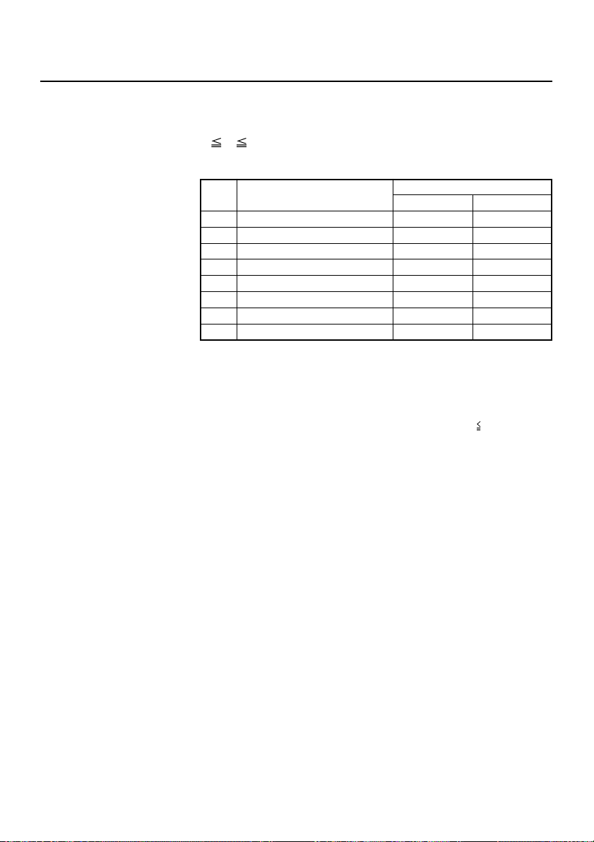
(4) Continuous paper detector status (When n = 4 is specified)
Bit Status Hex. Decimal
0 Unused 00 0
1 Unused 02 02
Paper found by Paper Near-end Sensor 1 00 0
2
Paper not found by Paper Near-end Sensor 1 04 4
Paper found by Paper Near-end Sensor 2 00 0
3
Paper not found by Paper Near-end Sensor 2 08 8
4 Unused 10 16
Paper found by Paper-end Sensor 00 0
5
Paper not found by Paper-end Sensor 20 32
Paper found by Presenter Sensor 00 0
6
Paper not found by Presenter Sensor 40 64
7 Unused 00 0
[See Also] DLE ENQ, GS a, GS r
— 12 —
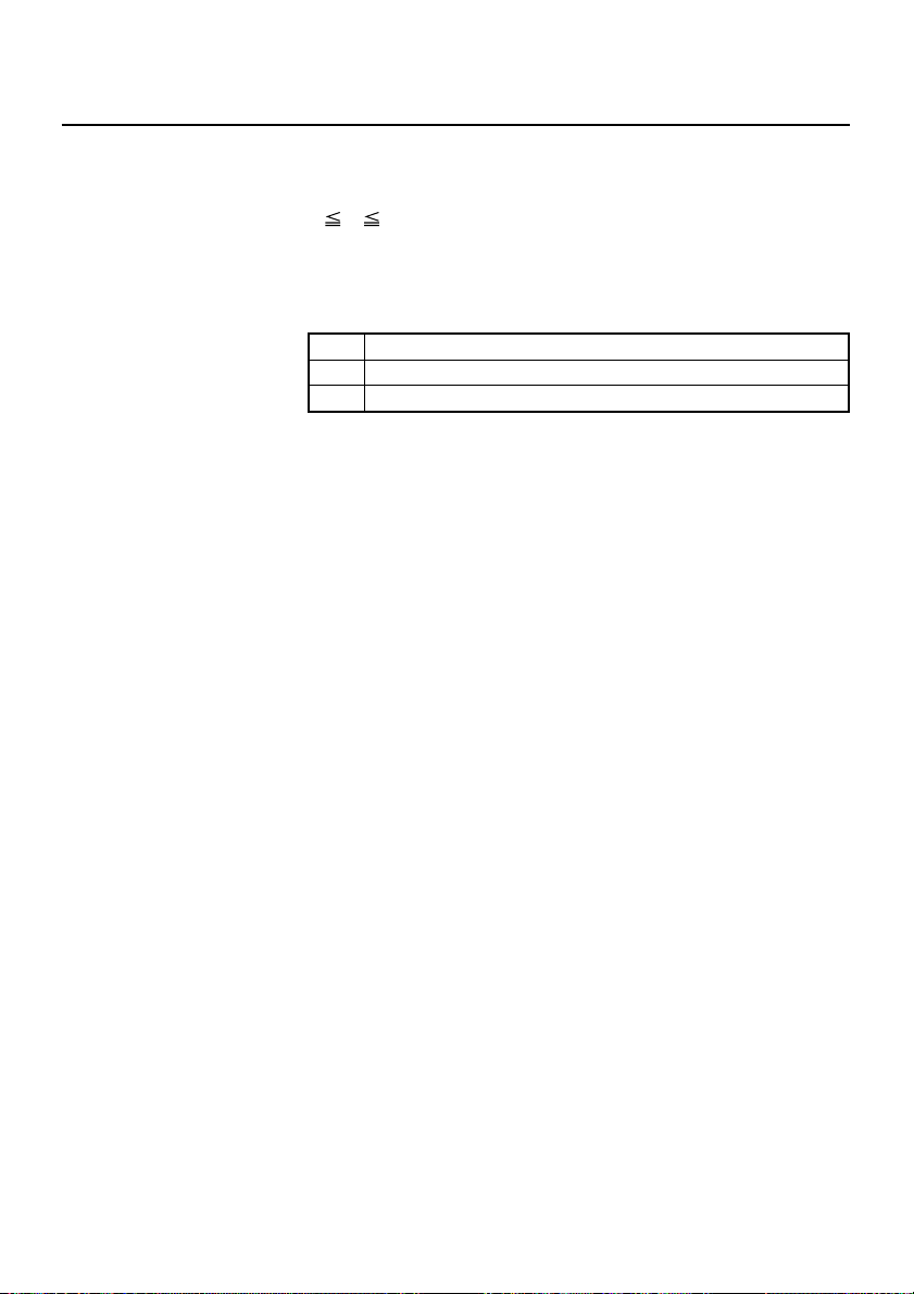
DLE ENQ n
[Function] Real-time request to printer
[Code] <10>H<05>H<n>
[Range] 1
[Outline] The printer responds in real-time to the request that the host
[Caution] • This command is only effective if an auto cutter error has
[See Also] DLE EOT
n 2
specifies with number “n”.
n Function
After recovering from an error, the printer resumes
1
printing from the beginning of the line where the error
occurred.
• This command is dealt with when it is received.
• This command is also executed even if the printer is in a
• If another data string of <10>H<05>H<n>(1
[Example 1]
If, for example, a command “ESC * m nL nH {d} k”, where d1 =
<10>H, d2=<05>H, d3=<01>H1, is given, the DLE ENQ n
command cannot be interleaved into the code string of another
command consisting of two bytes or more.
[Example 2]
• If the printer sends DLE ENQ 2 when the host has sent up to
• Even if DLE ENQ 2 is executed, the settings made by, for
The printer clears the receive buffer and the print buffer,
2
and then recovers from the error.
occurred.
receive-buffer full state.
n 2) is received,
the printer acts in the same way as with this command. The
user should, therefore, be reminded of this fact.
ESC 3 in its attempt to send ESC 3 n, the printer treats the ESC
3 as ESC 3 <10>H. Thus, the user should be careful.
example, ESC ! and ESC 3 retain the conditions when the error
occurred. A combined use of this command and ESC @ can
completely initialize the printer.
— 13 —

ESC FF
[Function] Printing data in PAGE MODE
[Code] <1B>H<0C>H
[Outline] Executes a batch printout of the data mapped in the entire print
area in PAGE MODE.
[Caution] • This command is only effective when PAGE MODE is selected.
• Mapped data, as well as the ESC T and ESC W settings, and
the character mapping position are held even after printing.
[See Also] FF, ESC L, ESC S
— 14 —

ESC SP n
[Function] Setting the right spacing of the character
[Code] <1B>H<20>H<n>
[Range] 0
[Outline] Sets the right spacing of character to [n × basic calculation pitch]
[Caution] • If the horizontal magnification of character is 2 or more, the
[Default] n = 0
[See Also] GS P
n 255
inches.
right spacing increases with the magnification.
• The right spacing can be set separately for the STANDARD
and PAGE MODES.
• The basic calculation pitch is set by GS P. Once defined, the
right spacing is not changed if the basic calculation pitch is
changed by GS P.
• Fractions resulting from calculation are corrected with the
minimum pitch of the mechanism, and the remainder is
omitted.
• In STANDARD MODE, this command uses the horizontal basic
calculation pitch (x).
• In PAGE MODE, the basic calculation pitch used by this
command depends on the start point:
(1) If the start point specified by ESC T is top left or bottom
right, the command uses the horizontal basic calculation
pitch (x).
(2) If the start point specified by ESC T is top right or bottom
left, the command uses the vertical basic calculation pitch
(y).
• The maximum right spacing is capable of approximately 31.906
mm (255/203 inches). A setting greater than this maximum is
trimmed to the maximum.
— 15 —

[Sample Program]
[Print Results]
LPRINT CHR$(&H1B) + “ ” + CHR$(0) ;
LPRINT “AAAAA” + CHR$(&HA) ;
LPRINT CHR$(&H1B) + “ ” + CHR$(1) ;
LPRINT “AAAAA” + CHR$(&HA) ;
LPRINT CHR$(&H1B) + “ ” + CHR$(12) ;
LPRINT “AAAAA” + CHR$(&HA) ;
END
AAAAA
← 0-dot space
AAAAA ← 1-dot space
AAAAA← 12-dots space
— 16 —
ESC ! n
[Function] Collectively specifying the printing mode
[Code] <1B>H<21>H<n>
[Range] 0
[Outline] Printing mode is assigned.
[Caution] • With double height and double width being specified
[Default] n = 0
[See Also] ESC E, ESC –, GS !
n 255
Bit Function
0 Character Font Font A Font B
1 Undefined
2 Undefined
3 Emphasis Canceled Specified
4 Double height Canceled Specified
5 Double width Canceled Specified
6 Undefined
7 Underline Canceled Specified
Value
01
simultaneously, quadruple characters are created.
• An underline is attached to the full character width, which,
however, is not attached to the part having been skipped by
the horizontal tab. Neither is it attached to 90
-right-turned
characters.
• The underline width is as specified by the <ESC –> command.
(The default setting is 1 dot width.)
• In case characters with different vertical magnification ratios
coexist on the same line, they are printed on the same base
line.
— 17 —
[Sample Program]
LPRINT CHR$(&H1B) + “!” + CHR$(&H00) + “H” ;
LPRINT CHR$(&H1B) + “!” + CHR$(&H01) + “H” ;
LPRINT CHR$(&H1B) + “!” + CHR$(&H08) + “H” ;
LPRINT CHR$(&H1B) + “!” + CHR$(&H10) + “H” ;
LPRINT CHR$(&H1B) + “!” + CHR$(&H20) + “H” ;
LPRINT CHR$(&H1B) + “!” + CHR$(&HB9) + “H” ;
LPRINT CHR$(&HA) ;
END
[Print Results]
Font A
Font B
Font A + Emphasis
∨∨∨
∨∨ ∨∨
Font B + Emphasis + Quadruple + Underline
Font A + Underline
Font A + Double Width
Font A + Double Height
— 18 —

ESC $ n1 n2
[Function] Specifying the absolute positions
[Code] <1B>H<24>H<n1><n2>
[Range] 0
[Outline] The printing start position is specified with the number of dots
[Caution] The basic calculation pitch is set by GS P. After the line feed
[Default] The initial value is not defined.
[See Also] ESC \, GS P, GS \, GS $
n1 255
0
n2 255
(1/203 inch unit) from the beginning of a line.
• The number of dots is divided by 256, whose quotient is taken
as “n2” and the residual as “n1”.
• Therefore, the printing start position is equal to n1 + n2 × 256
from the beginning of a line.
width is set, if the basic calculation by GS P leaves a fraction,
the fraction is corrected with the minimum pitch of the
mechanism, and the remainder is omitted.
In STANDARD MODE, this command uses the horizontal (Paper
feed direction) basic calculation pitch (x).
In PAGE MODE, this command acts differently depending on
the start point:
(1) If the start point specified by ESC T is top right or bottom
left, the command uses the vertical (Paper feed direction)
basic calculation pitch (y).
(2) If the start point specified by ESC T is top left or bottom
right , the command uses the horizontal (Perpendicular to
the paper feed direction) basic calculation pitch (x).
Specification beyond the end of the line is ignored.
— 19 —

[Sample Program]
LPRINT CHR$(&H1B) + “$” ;
LPRINT CHR$(0) + CHR$(0) + “A” ;
LPRINT CHR$(&H1B) + “$” ;
LPRINT CHR$(50) + CHR$(0) + “B” ;
LPRINT CHR$(&H1B) + “$” ;
LPRINT CHR$(0) + CHR$(1) + “C” ;
LPRINT CHR$(&HA) ;
LPRINT CHR$(&H1B) + “$” ;
LPRINT CHR$(100) + CHR$(0) + “A” ;
LPRINT CHR$(&H1B) + “\” ;
LPRINT CHR$(&HC2) + CHR$(&HFF) + “B” ;
LPRINT CHR$(&HA);
END
[Print Results]
Absolute Position Specified
0 50 100 256
<
AB C
<
<
<
BA
<
Relative Position Specified
–62
— 20 —
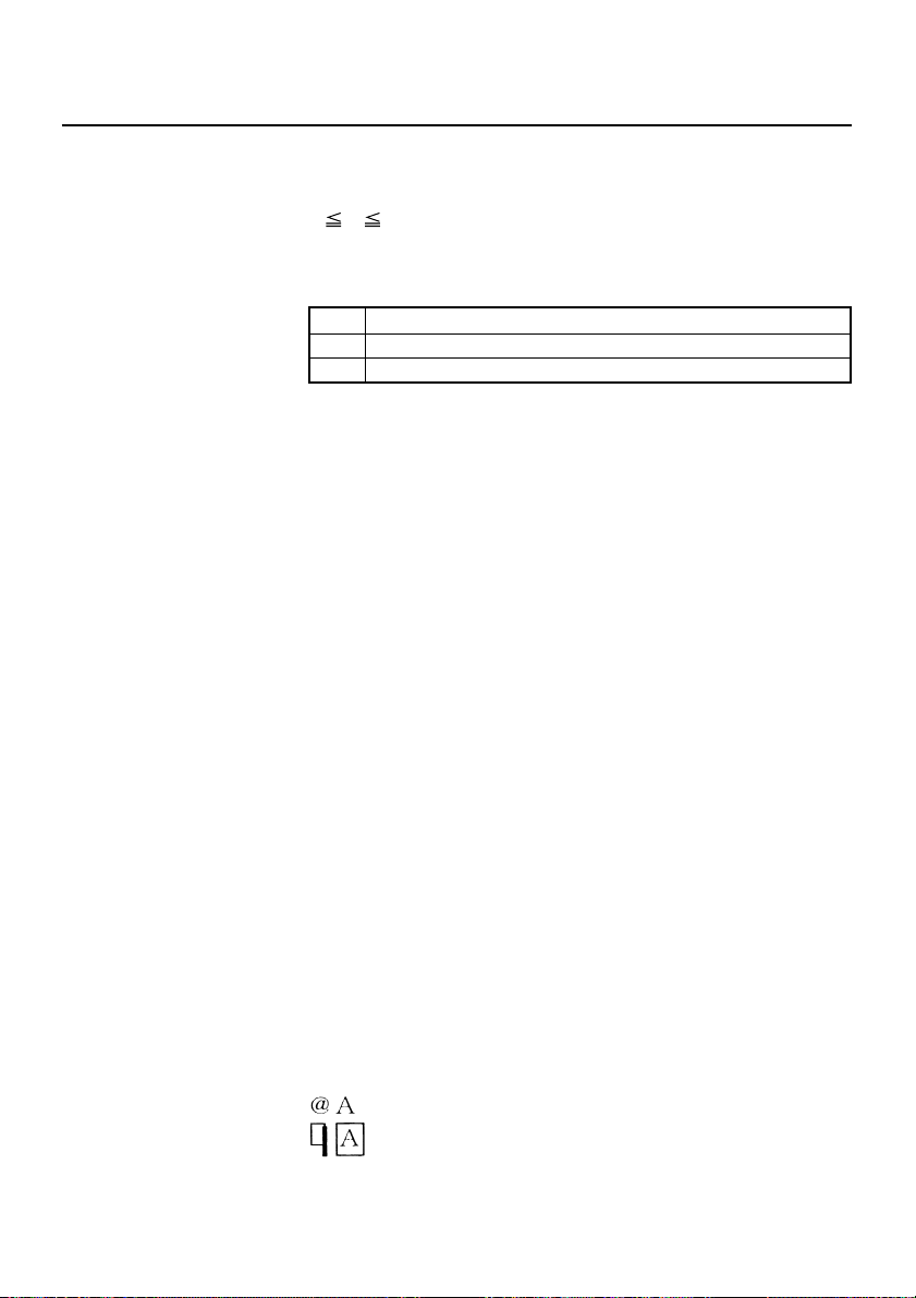
ESC % n
[Function] Specifying/Canceling download character set
[Code] <1B>H<25>H<n>
[Range] 0
[Outline] Specifying/canceling download characters.
[Caution] Download characters and download bit images cannot be
[Default] n = 0
[See Also] ESC &
[Sample Program]
SETCHR:
n 255
• Only the lowest bit (n0) is valid for n.
n0 Function
0 Canceling download character set
1 Specifying download character set
defined simultaneously.
GOSUB SETCHR
LPRINT CHR$(&H1B) + “%” + CHR$(0) ;
LPRINT “@A” + CHR$(&HA) ;
LPRINT CHR$(&H1B) + “%” + CHR$(1) ;
LPRINT “@A” +CHR$(&HA) ;
END
LPRINT CHR$(&H1B) + “&” ;
LPRINT CHR$(3) + “@” + “A”;
FOR J=1 TO 2
READ REP
LPRINT CHR$(REP) ;
FOR I=1 TO REP∗3
READ D
LPRINT CHR$(D)
NEXT I
NEXT J
RETURN
DATA 6
DAT A &HEF, &H80, &H00
DATA &H80, &H80, &H00
DATA &H80, &H80, &H00
DATA &H80, &H80, &H00
DATA &HFF, &HFF, &HFF
DATA &HFF, &HFF, &HFF
DATA 12
DATA &HFF, &HFF, &HFF
DATA &H80, &H07, &HF9
DATA &H80, &HFF, &HF9
DATA &H87, &HFE, &H01
DATA &H9F, &H06, &H01
DATA &HF8, &H06, &H01
DATA &HF8, &H06, &H01
DATA &H9F, &H06, &H01
DATA &H87, &HFE, &H01
DATA &H80, &HFE, &HF9
DATA &H80, &H07, &HF9
DATA &HFF, &HFF, &HFF
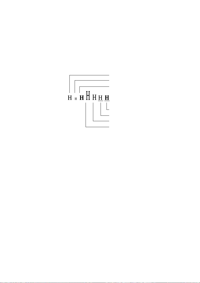
[Print Results]
← Internal Character Set
← Download Character
— 21 —
ESC & s n m [a [p] s×a] m–n+1
[Function] Defining the download characters
[Code] <1B>H<26>H<s>H<n><m>[<a><p1><p2> ⋅ ⋅ <ps × a>]m-n+1
[Range] s = 3
32
n m 126
a 12 (Font A)
0
0
a 9 (Font B)
p1 ⋅ ⋅ ps × a 255
0
[Outline] Defines the font of download characters of alphanumeric
characters.
• “s” indicates the number of bytes in vertical direction.
• “n” indicates the start character code and “m” the end
character code. To define only one character, set n=m.
• Character codes definable includes 95 ASCII codes in total in
the range of <20>H to <7E>H.
• “a” indicates the number of dots to be defined in horizontal
direction.
• “p” is the data to be defined, which indicate a pattern equal to
“a” dots in horizontal direction from the left end. The rest of
the pattern on the right side is filled with space.
The number of data to be defined is s × a.
• Download characters thus defined remain valid until
redefinition, ESC @, GS
power OFF is performed.
[Caution] • Download characters and download bit images cannot be
defined simultaneously.
• Running this command clears the definition of the download
bit image.
[Default] Same as the internal character set.
[See Also] ESC %, ESC ?
, FS q execution, ESC ? deletion or
*
— 22 —
[Example]
12dot
9dot
24dot
p1 p4
p2
p3
p5
p6
p34
MSB
p35
p36
Font A Font B
LSB
24dot
p1 p4
p2
p3
p5
p6
p25
MSB
p26
p27
LSB
Create each data bit by setting “1” for a printed dot and “0” for
an unprinted dot.
[Sample Program] Refer to Sample Program and Print Results for ESC % on
page 23.
— 23 —
ESC * m n1 n2 [ d ] k
[Function] Specifying the bit image mode
[Code] <1B>H<2A>H<m><n1><n2> [<d>] k
[Range] m= 0, 1, 32, 33
0
n1 255
0
n2 3
0
d 255
k = n1 + 256 × n2 (m = 0, 1)
k = (n1+ 256 × n2) × 3 (m = 32, 33)
[Outline] According to the number of dots specified in “n1”, “n2”, specify
the bit image of mode “m”.
• The number of dots printed is divided by 256, whose quotient
is taken as n2 and residual as “n1”.
• The total number of dots printed in the horizontal direction is
equal to n1 + (256 × n2).
• When bit image data have been input in excess of dot positions
that can be printed on one line, the excess data are discarded.
• ”d” is bit image data. Bits to be printed are specified as “1”
and those not as “0”.
• The bit image modes specified by m are shown as follows:
m
0 8-dots single density 8 67 DPI 101 DPI 288
1 8-dots double density 8 67 DPI 203 DPI 576
32 24-dots single density 24 203 DPI 101 DPI 288
33 24-dots double density 24 203 DPI 203 DPI 576
Mode
Vertical Direction Horizontal Direction
No. of Dots Dot Density Dot Density Max. No. of Dots
[Caution] • When the value of m is out of the above range, the data
following after n1 is processed as normal printing data.
• After completion of bit image printing, the printer returns to
normal data processing mode.
— 24 —
[Sample Program]
LPRINT CHR$(&H1B) + “*”;
LPRINT CHR$(0) + CHR$(20) + CHR$(0);
GOSUB IMG1
LPRINT CHR$(&HA);
LPRINT CHR$(&H1B + “
LPRINT CHR$(1) + CHR$(20) + CHR$(0);
GOSUB IMG1
LPRINT CHR$(&HA);
LPRINT CHR$(&H1B) + “
LPRINT CHR$(32) + CHR$(20) + CHR$(0);
GOSUB IMG2
LPRINT CHR$(&HA);
LPRINT CHR$(&H1B) + “
LPRINT CHR$(33) + CHR$(20) + CHR$(0);
GOSUB IMG2
LPRINT CHR$(&HA);
END
IMG1:
LPRINT CHR$(&HFF);
FOR I=1 TO 18
”;
*
”;
*
”;
*
LPRINT CHR$(&H85);
NEXT I
LPRINT CHR$(&HFF);
RETURN
IMG2:
LPRINT CHR$(&HFF);
LPRINT CHR$(&HFF);
LPRINT CHR$(&HFF);
FOR I=1 TO 18
LPRINT CHR$(&H80);
LPRINT CHR$(&H00);
LPRINT CHR$(&H05);
NEXT I
LPRINT CHR$(&HFF);
LPRINT CHR$(&HFF);
LPRINT CHR$(&HFF);
RETURN
[Print Results]
← 8-dots single density
← 8-dots double density
← 24-dots single density
← 24-dots double density
— 25 —
ESC – n
[Function] Specifying/Canceling underline
[Code] <1B>H<2D>H<n>
[Range] 0
[Outline] Specifying/canceling an underline.
[Caution] • An underline is attached to the full character width. It is,
[Default] n = 0
[See Also] ESC !, FS -
[Sample Program]
n 2
48
n 50
n Function
0.48 Canceling an underline
1.49 Specifying an underline for 1-dot width
2.50 Specifying an underline for 2-dots width
however, not attached to the part having been skipped by
horizontal tab command.
• An underline is not attached to a 90
- right-turned characters.
LPRINT CHR$(&H1B) + “-” + CHR$(0);
LPRINT “AAAAA”;
LPRINT CHR$(&H1B) + “-” + CHR$(1);
LPRINT “AAAAA” + CHR$(&HA);
END
[Print Results]
Underline Canceled
←→
AAAAAAAAAA
←→
Underline Specified
— 26 —
ESC 2
[Function] Specifying 1/6-inch line feed rate
[Code] <1B>H<32>H
[Outline] The line feed rate per line is specified by 1/6 inch.
[Caution] Line feed rate can be specified respectively for both ST ANDARD
MODE and PAGE MODE.
[Sample Program]
[Print Results]
LPRINT “AAAAA” + CHR$(&HA);
LPRINT CHR$(&H1B) + “3” + CHR$(0);
LPRINT “AAAAA” + CHR$(&HA);
LPRINT CHR$(&H1B) + “3” + CHR$(50);
LPRINT “AAAAA” + CHR$(&HA);
LPRINT CHR$(&H1B) + “2”;
LPRINT “AAAAA” + CHR$(&HA);
LPRINT “AAAAA”;
LPRINT CHR$(&H1B) + “J” + CHR$(100);
LPRINT “AAAAA” + CHR$(&HA);
LPRINT “AAAAA” + CHR$(&HA);
END
AAAAA
AAAAA
AAAAA
AAAAA
<
1/6-inch line feed
<
<
0/203-inch line feed
<
<
50/203-inch line feed
<
<
1/6-inch line feed
<
<
AAAAA
AAAAA
AAAAA
100 /203-inch line feed
<
<
1/6-inch line feed
<
— 27 —

ESC 3 n
[Function] Setting line feed rate of minimum pitch
[Code] <1B>H<33>H<n>
[Range] 0
[Outline] Sets the line feed width per line to [n × basic calculation pitch]
[Caution] The line feed width can be set separately for the STANDARD
[Default] Approx 4.23 mm
[See Also] ESC 2, GS P
n 255
inches.
and PAGE MODES.
The basic calculation pitch is set by GS P. Once defined, the line
feed width is not changed if the basic calculation pitch is changed
by GS P.
Fractions resulting from calculation are corrected with the
minimum pitch of the mechanism, and the remainder is omitted.
• In STANDARD MODE, this command uses the vertical (Paper
feed direction) basic calculation pitch (y).
• In PAGE MODE, this command acts differently depending on
the start point:
(1) If the start point specified by ESC T is top left or bottom
right, the command uses the vertical (Paper feed direction)
basic calculation pitch (y).
(2) If the start point specified by ESC T is top right or bottom
left, the command uses the horizontal (Perpendicular to
the paper feed direction) basic calculation pitch (x).
The maximum settable line feed width is 1016 mm (40 inches).
A setting greater than this maximum is trimmed to the
maximum.
— 28 —

ESC = n
[Function] Data input control
[Code] <1B>H<3D>H<n>
[Range] 0
[Outline] Selecting equipment for which data input from the host is valid.
[Caution] • Even when the printer has not been selected, it can become
[Default] n = 1
n 255
• Each bit of “n” indicates as follows:
Bit Equipment
0 Printer Invalid Valid
1 Not defined
2 Not defined
3 Not defined
4 Not defined
5 Not defined
6 Not defined
7 Not defined
Value
01
• When the printer has not been selected, this printer abandons
all the received data until it is selected by this command.
BUSY state through printer operation.
• When the printer is deselected, this printer discards all the
data until it is selected with this command. (Except DLE EOT,
DLE ENQ, and DLE DC4)
— 29 —

ESC ? n
[Function] Deleting download characters
[Code] <1B>H<3F>H<n>
[Range] 32
[Outline] Deletes the downloaded characters of specified code.
[Caution] • The character “n” indicates the character code used to delete
[See Also] ESC &, ESC %
n 126
the defined pattern. After the deletion, characters are printed
in the same pattern as the internal characters.
• This command deletes the code-defined pattern of the
character font selected by ESC !.
• This command is ignored if the specified character code is
undefined.
— 30 —

ESC @
[Function] Initializing the printer
[Code] <1B>H<40>H
[Outline] Clears data stored in the print buffer and brings various settings
to the initial state (Default state).
[Caution] • The settings of DIP switches are not read again.
• Data inside the internal input buffer is not cleared.
• Macro definitions are not cleared.
• NV bit image definitions are not cleared.
• Data in the user NV memory is not cleared.
[Sample Program]
[Print Results]
LPRINT CHR$(&H1B) + “!” + CHR$(&H30);
LPRINT CHR$(&H1B) + “V” + CHR$(1);
LPRINT “AAA” + CHR$(&HA);
LPRINT CHR$(&H1B) + “@”;
LPRINT “AAA” + CHR$(&HA);
END
A
A
A
← Each setting has been
AAA
initialized by this command.
— 31 —

ESC D [ n ] k NUL
[Function] Setting horizontal tab position
[Code] <1B>H<44>H [<n>] k<00>
[Range] 1
[Outline] Specifying a horizontal tab position.
[Caution] When the data, <n> k, is equal to or smaller than its preceding
[Default] • Tab positions are set at eight-character intervals (9th., 17th.,
[See Also] HT
[Sample Program] Refer to Sample Program and Print Results for HT on page 6.
n 255
0
k 32
• “n” indicates the number of columns from the beginning to
the horizontal tab position. Note, however, that “n= set position
– 1”. For example, to set the position at 9th column, n=8 is to
be specified.
• “k” denotes the number of horizontal tab positions you want
to set.
• The tab position is set at a position where it is “character width
× n” from the beginning of a line. The character width, at this
time, includes the space on the right. In double width
characters, it is made double the ordinary case.
• Tab positions that can be specified are maximum 32.
Specifying tab positions exceeding this limit is ignored.
• <n> k, which denotes a setting position, is input in the
increasing order and ends at <00> H.
• ESC D <NUL> clears all the set tab positions. Following
clearing, the horizontal tab command is ignored.
data, <n> k-1, it is assumed that tab setting is finished. If this is
the case, the next data onward will be processed as normal
data.
When the data, <n> k, exceeds a 1-line print area, set the
horizontal tab position, as “Set column position = Maximum
print columns + 1”. The horizontal tab position does not change
even if the character width is altered after setting the horizontal
tab position.
25th. columns) of Font A.
— 32 —
ESC E n
[Function] Specifying/Canceling Emphasis Printing
[Code] <1B>H<45>H<n>
[Range] 0
[Outline] Specifying/canceling the emphasized characters.
[See Also] ESC !
[Sample Program]
n 255
• “n” is valid only for the lowest bit (n0).
• Control by the lowest bit (n0) is shown as follows:
n0 Function
0 Canceling emphasis printing
1 Specifying emphasis printing
• This is effective to all characters.
• Dot configuration of a emphasized character includes one extra
dot added at its side.
• Emphasis printing can also be specified using ESC !, however ,
ESC E or ESC !, whichever command is processed last, takes
precedence.
LPRINT CHR$(&H1B) + “E” + CHR$(0);
LPRINT “AAABBB” + CHR$(&HA);
LPRINT CHR$(&H1B) + “E” + CHR$(1);
LPRINT “AAABBB” + CHR$(&HA);
END
[Print Results]
AAABBB
AAABBB
← Emphasis canceled
← Emphasis specified
— 33 —

ESC G n
[Function] Specifying/Canceling Double strike printing
[Code] <1B>H<47>H<n>
[Range] 0
[Outline] Specifying/canceling the double strike printing.
[Caution] With this printer,double-strike printing and emphasis printing
[See Also] ESC E
[Sample Program]
n 255
• “n” is valid only for the lowest bit (n0).
• Control by the lowest bit (n0) is shown as follows.
n0 Function
0 Canceling double strike printing
1 Specifying double strike printing
This is effective to all characters.
provide completely the same results.
LPRINT CHR$(&H1B) + “G” + CHR$(0);
LPRINT “AAABBB” + CHR$(&HA);
LPRINT CHR$(&H1B) + “G” + CHR$(1);
LPRINT “AAABBB” + CHR$(&HA);
END
[Print Results]
AAABBB
AAABBB
← Double strike printing canceled
← Double strike printing specified
— 34 —

ESC J n
[Function] Printing and feeding paper in minimum pitch
[Code] <1B>H<4A>H<n>
[Range] 0
[Outline] Prints the data held in the print buffer and feeds paper by [n ×
[Caution] The line feed width can be set separately for the STANDARD
[Default] The initial value is not defined.
[Sample Program] Refer to Sample Program and Print Results for ESC 2 on
n 255
basic calculation pitch] inches. The beginning of the line is taken
as the next print start position.
and PAGE MODES.
• This command does not affect the line feed width defined by
ESC 2 or ESC 3.
• The basic calculation pitch is set by GS P.
• Fractions resulting from calculation are corrected with the
minimum pitch of the mechanism, and the remainder is
omitted.
• In STANDARD MODE, this command uses the vertical (Paper
feed direction) basic calculation pitch (y).
• In PAGE MODE, this command acts differently depending on
the start point:
(1) If the start point specified by ESC T is top left or bottom
right, the command uses the vertical (Paper feed direction)
basic calculation pitch (y).
(2) If the start point specified by ESC T is top right or bottom
left, the command uses the horizontal (Perpendicular to the
paper feed direction) basic calculation pitch (x).
The maximum settable line feed width is 1016 mm (40 inches).
A setting greater than this maximum is trimmed to the
maximum. The beginning of the line is taken as the next print
start position.
page 29.
— 35 —

ESC L
[Function] Selecting PAGE MODE
[Code] <1B>H<4C>H
[Outline] Switches from STANDARD MODE to PAGE MODE.
[Caution] • This command is only effective if it entered at the beginning
of a line.
• This command is not effective if it is entered when in PAGE
MODE.
• STANDARD MODE is restored when printing specified by FF
is finished or when ESC S is issued.
• The character mapping start position will be the point specified
by ESC T in the print area specified by ESC W.
• The commands listed below, which have separate settings for
PAGE MODE and STANDARD MODE, are changed to the
settings for PAGE MODE use.
(1) Spacing setting: ESC SP
(2) Line feed width setting: ESC 2, ESC 3
• The following commands are valid only in PAGE MODE.
(1) ESC V Specifying/canceling 90°-right-turned characters.
(2) ESC a Aligning the characters.
(3) ESC { Specifying/canceling the inverted characters.
(4) GS L Setting the left margin.
(5) G3S W Setting the print area width.
• ESC @ restores STANDARD MODE.
[See Also] FF, CAN, ESC FF, ESC S, ESC T, ESC W, GS $, GS \
— 36 —

ESC M n
[Function] Selection of character fonts
[Code] <1B>H<4D>H<n>
[Definition value] n=0, 1, 48, 49
[Outline] Selects character fonts.
n Function
0, 48 Selection of font A (12 × 24)
1, 49 Selection of font B (9 × 24)
[Details] ESC ! can also select fonts, but the setting made by the command
that has last been processed becomes valid.
[Reference] ESC !
— 37 —
ESC R n
[Function] Selecting the international character set
[Code] <1B>H<52>H<n>
[Range] 0
[Outline] Depending on the value of “n”, one of the following character
[Default] n = 0
[See Also] Character Code Table (International Character Set)
n 10
sets is specified;
n Character Set
0 U.S.A.
1 France
2 Germany
3 U.K.
4 Denmark I
5 Sweden
6 Italy
7 Spain I
8 Japan
9 Norway
10 Denmark II
11 Spain II
12 Latin America
13 Korea
— 38 —

ESC S
[Function] Selecting STANDARD MODE
[Code] <1B>H<53>H
[Outline] Switches from PAGE MODE to STANDARD MODE.
[Caution] • This command is only effective if it is entered when in PAGE
MODE.
• Any data mapped in PAGE MODE is erased.
• After this command is executed, the beginning of the line is
taken as the next print start position.
• The print area defined by ESC W is initialized.
• The commands listed below, which have separate settings for
STANDARD MODE and PAGE MODE, are changed to the
settings for STANDARD MODE use.
(1) Spacing setting: ESC SP
(2) Line feed width setting: ESC 2, ESC 3
• STANDARD MODE is selected when the printer is turned on
or reset,or when ESC @ is executed.
[See Also] FF, ESC FF, ESC L
— 39 —

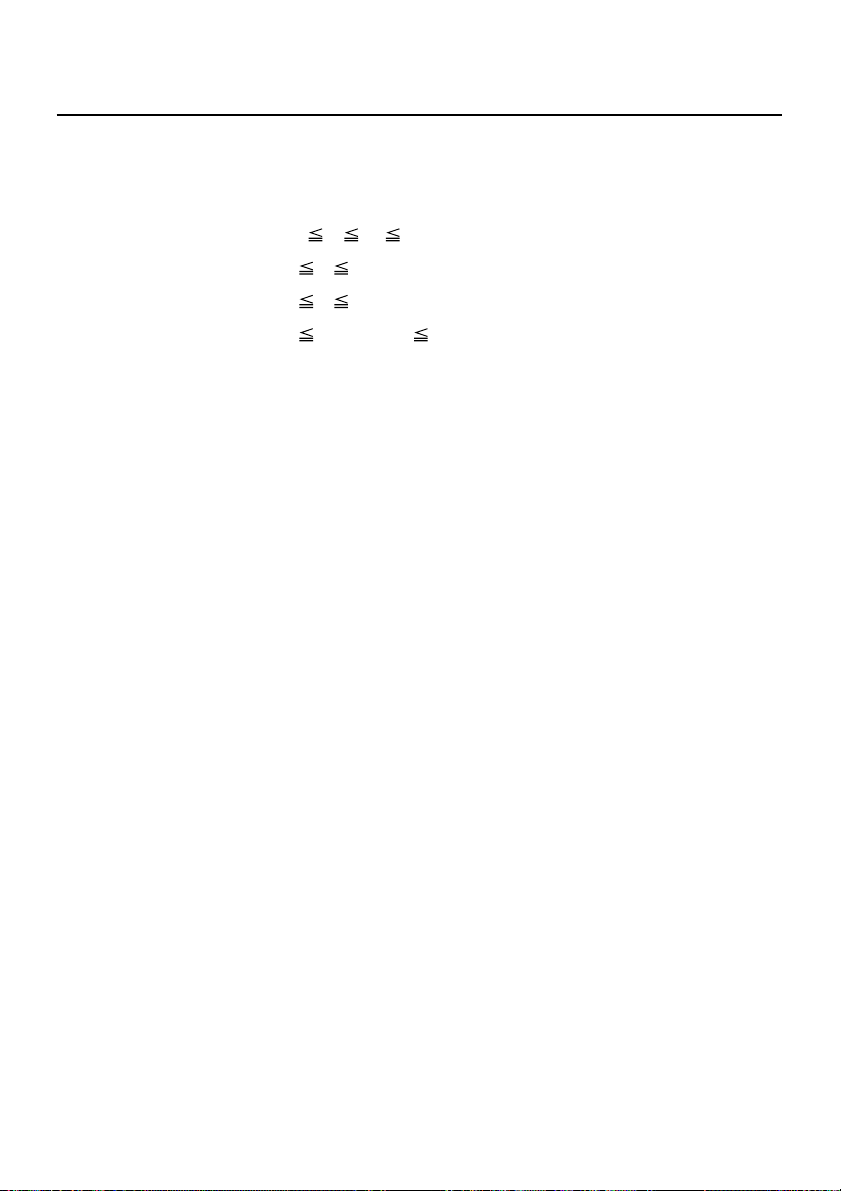
ESC T n
[Function] Selecting the character printing direction in PAGE MODE
[Code] <1B>H<54>H<n>
[Range] 0
[Outline] Selects the direction and start point of character printing in
n 3
48
n 51
PAGE MODE.
n Printing direction Start point
0, 48 Left to right Top left (“A” in the figure)
1, 49 Bottom to top Bottom left (“B” in the figure)
2, 50 Right to left Bottom right (“C” in the figure)
3, 51 Top to bottom Top right (“D” in the figure)
Reference
<
<
Print Area
Paper Feed Direction
[Caution] • When STANDARD MODE is selected, this command only
executes the internal flagging of the printer without affecting
the printing in STANDARD MODE.
• The character mapping position will be the start point of the
print area specified by ESC W.
• The basic calculation pitch (x or y) used by the following
commands varies with the start point.
(1) If the start point is the top left or bottom right (The
characters are mapped in the direction perpendicular to
the paper feed),
• Commands using x: ESC SP, ESC S, ESC \
• Commands using y: ESC 3, ESC J, GS $, GS \
(2) If the start point is the top right or bottom left (The
characters are mapped in the paper feed direction),
• Commands using x: ESC 3, ESC J, GS $, GS \
• Commands using y: ESC SP, ESC S, ESC \
[Default] n = 0
[See Also] ESC $, ESC L, ESC W, ESC \, GS $, GS P, GS \
— 40 —
ESC V n
[Function] Specifying/Canceling 90°-right-turned characters
[Code] <1B>H<56>H<n>
[Range] n = 0, 1, 48, 49
[Outline] Specifying/canceling 90°-right- turned characters.
n Function
0, 48 Canceling 90°-right- turned Characters
1, 49 Specifying 90°-right- turned Characters
[Caution] No underlines are attached to 90°-right- turned characters .
[Default] n = 0
[Sample Program]
LPRINT CHR$(&H1B) + “V” + CHR$(0);
LPRINT “AAAAA”;
LPRINT CHR$(&H1B) + “V” + CHR$(1);
LPRINT “AAAAA” + CHR$(&HA);
END
[Print Results]
90° Rotation Canceled
←→
AAAAA
A
A
A
A
A
←→
90° Rotation Specified
— 41 —

ESC W xL xH yL yH dxL dxH dyL dyH
[Function] Defining the print area in PAGE MODE
[Code] <1B>H<57>H<xL><xH><yL><yH><dxL><dxH><dyL><dyH>
[Range] 0
[Outline] Defines the location and size of the print area.
[Caution] • When STANDARD MODE is selected, this command only
xL, xH, yL, yH, dxL, dxH, dyL, dyH 255,
except for dxL = dxH = 0 or dyL = dyH = 0
• Horizontal start point = [(xL + xH × 256) × basic calculation
pitch] inches
• Vertical start point = [(yL + yH × 256) × basic calculation pitch]
inches
• Horizontal length = [(dxL + dxH × 256) × basic calculation pitch]
inches
• Vertical length = [(dyL + dyH × 256) × basic calculation pitch]
inches
executes the internal flagging of the printer without affecting
the printing in STANDARD MODE.
• If the horizontal start point or vertical start point is out of the
printable area, this command is canceled and the next data is
handled as normal data.
• If the horizontal length or vertical length is 0, this command is
canceled and the next data is handled as normal data.
• The character mapping position will be the start point specified
by ESC T in the print area.
• If the “horizontal start point + horizontal length” is greater
than the horizontal printable area, the “horizontal printable
area - horizontal start point” is taken as the horizontal length.
• If the “vertical start point + vertical length” is greater than the
vertical printable area, the “vertical printable area - vertical
start point” is taken as the vertical length.
• The basic calculation pitch is defined by GS P. Once defined,
the print area is not changed if the basic calculation pitch is
changed by GS P.
• Fractions resulting from calculations are corrected with the
minimum pitch of the mechanism, and the remainder is
omitted.
• The horizontal start point and horizontal length are calculated
with the basic calculation pitch (x). The vertical start point and
vertical length are calculated with the basic calculation pitch
(y).
— 42 —

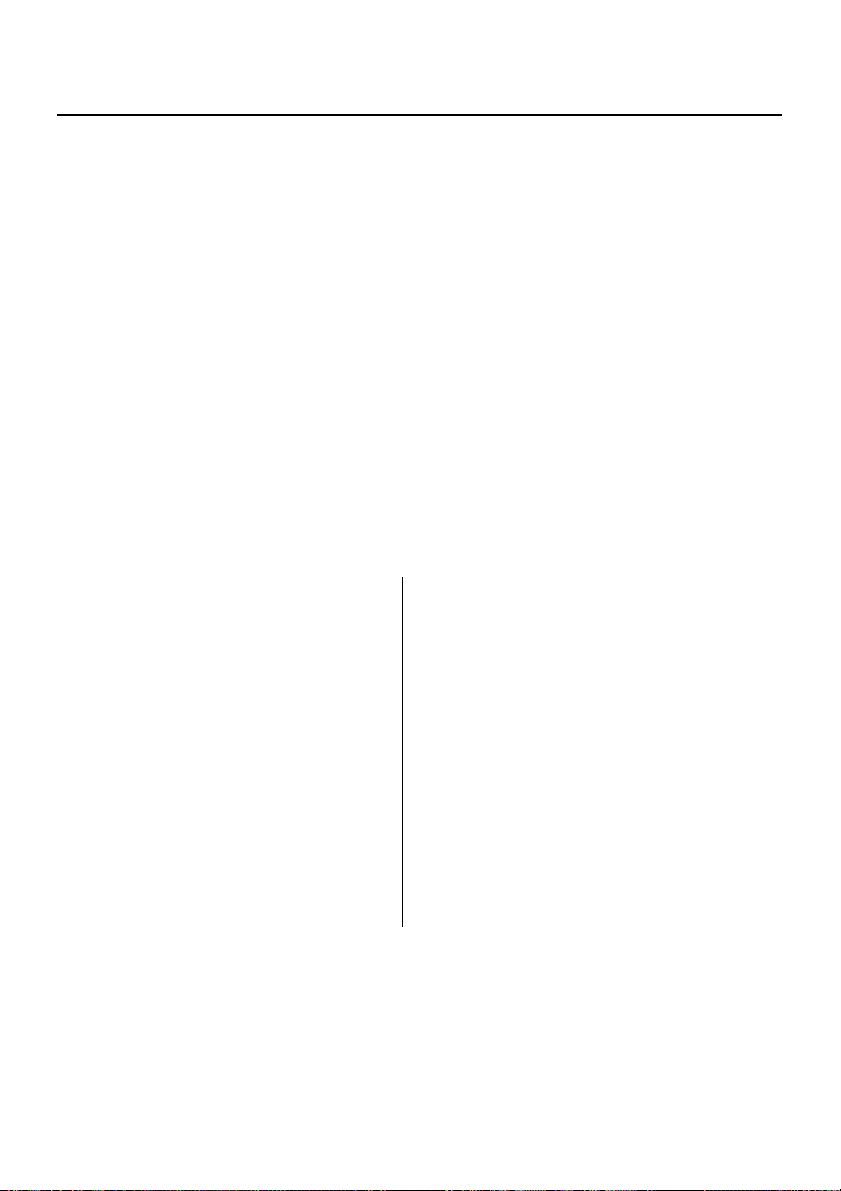
• The figure below illustrates the print area, where X = horizontal
start point, Y=vertical start point, Dx=horizontal length, and
Dy=vertical length.
Print Area
The printable area for this printer is approximately 72.070 mm
(576/203 inches) horizontally and 117 mm (1662/360 inches)
vertically.
[Default] xL=xH=yL=yH=0
dxL=64, dxH=2, dyL=126, dyH=6 (When 58mm wide paper is
used: dxL=176, dxH=1)
[See Also] CAN, ESC L, ESC T, GS P
Paper
<
Paper Feed Direction
— 43 —

ESC \ nL nH
[Function] Specifying the relative position
[Code] <1B>H<5C>H<nL><nH>
[Range] 0
[Outline] This command specifies the next print start position in a relative
[Caution] • Specification of a position outside the print area is ignored.
[See Also] ESC $, GS P
[Sample Program] Refer to Sample Program and Print Results for ESC $ on
nL 255
0
nH 255
position with respect to the current position. The next print start
position will be at a point of [(nL + nH × 256) × basic calculation
pitch] inches away from the current position.
• If a new position is specified to the right of the current position
in the direction of printing, it should be specified as positive
(+). If it is to the left, it should be as negative(-).
• A negative value is the complement of 65536. For example, to
move the position by N pitches to the left, specify it as:
nL + nH × 256 = 65536 - N
• The basic calculation pitch is set by GS P.
• Fractions resulting from calculation are corrected with the
minimum pitch of the mechanism, and the remainder is
omitted.
• In STANDARD MODE, this command uses the horizontal basic
calculation pitch (x).
• In PAGE MODE, this command acts differently depending on
the start point:
(1) If the start point specified by ESC T is top left or bottom
right, the command specifies the relative position in the
direction perpendicular to the paper feed (The character’ s
side-to-side direction), using the horizontal basic
calculation pitch (x).
(2) If the start point is top right or bottom left, the command
specifies the relative position in the paper feed direction
(The character’s side-to-side direction), using the vertical
basic calculation pitch (y).
page 21.
— 44 —

ESC a n
[Function] Aligning the characters
[Code] <1B>H<61>H<n>
[Range] 0
[Outline] All the printed data within one line are aligned in the specified
[Caution] • This command is valid only when it is inputted at the beginning
[Default] n = 0
[Sample Program]
[Print Results]
n 2
48
n 50
position.
• Depending on the value “n”, positional alignment is carried
out as shown in the table below:
n Position
0,48 Left end alignment
1,49 Centering
2,50 Right end alignment
of a line.
• This command does not affect the PAGE MODE.
LPRINT CHR$(&H1B) + “a” + CHR$(0);
LPRINT “AAAAA” + CHR$(&HA);
LPRINT CHR$(&H1B) + “a” + CHR$(1);
LPRINT “AAAAA” + CHR$(&HA);
LPRINT CHR$(&H1B) + “a” + CHR$(2);
LPRINT “AAAAA” + CHR$(&HA);
END
<
AAAAA
AAAAA
AAAAA
Left-justified Centered Right-justified
Paper Feed
Direction
— 45 —

ESC c 3 n
[Function] Selecting the Paper Sensor valid for a paper end signal output
[Code] <1B>H<63>H<33>H<n>
[Range] 0
[Outline] This command selects by which Paper Sensor a paper end signal
[Caution] This command is valid only for the parallel interface.
[Default] n = 15
n 255
should be output. Each bit for “n” has the following meaning:
Bit Position
0 Paper Near-end Disabled Enabled
1 Paper Near-end Disabled Enabled
2 Paper end Disabled Enabled
3 Paper end Disabled Enabled
4 Undefined
5 Undefined
6 Undefined
7 Undefined
Value
01
— 46 —

ESC c 4 n
[Function] Selecting the Paper Near-end Sensor valid for print stop
[Code] <1B>H<63>H<34>H<n>
[Range] 0
[Outline] This command selects the Paper Near-end Sensor which helps
[Default] n = 0
n 255
to stop printing when the paper supply almost runs out.
Each bit for “n” has the following meaning:
Bit Position
0 Paper Near-end Disabled Enabled
1 Paper Near-end Disabled Enabled
2 Undefined
3 Undefined
4 Undefined
5 Undefined
6 Undefined
7 Undefined
Value
01
This printer can only select one kind of Paper Sensor, a Paper
Near-end Sensor.
— 47 —
ESC c 5 n
[Function] Enabling/Disabling the panel switches
[Code] <1B>H<63>H<35>H<n>
[Range] 0
[Outline] Enabling/disabling the FEED switch.
[Caution] When the panel switch is disabled with this command, the FEED
[Default] n = 0
[Sample Program]
LPRINT CHR$(&H1B) + “c5” + CHR$(0);
LPRINT CHR$(&H1B) + “c5” + CHR$(1);
n 255
• “n” is valid only in the lowest bit.
n0 Condition
0 FEED switch valid
1 FEED switch invalid
switch is also disabled. Therefore, the paper cannot be fed by
operating the FEED switch. Regardless of the setting of this
command, the FEED switch is always enable while the switch is
being waited for at the time of macro execution.
← When enabling the FEED switch
← When disabling the FEED switch
— 48 —

ESC d n
[Function] Printing and feeding the paper by “n” lines
[Code] <1B>H<64>H<n>
[Range] 0
[Outline] Prints data in the print buffer and feeds paper by “n” lines.
[Caution] If [n × line feed width] exceeds approximately 1016 mm, this
[Default] The initial value is not defined.
[Sample Program]
n 255
• Specified lines do not remain.
• The beginning of the line is specified as the next print start
position.
command feeds paper by approximately 1016 mm (40 inches).
LPRINT “AAAAA”;
LPRINT CHR$(&H1B) + “d” + CHR$(2);
LPRINT “AAAAA” + CHR$(&HA);
END
[Print Results]
AAAAA
AAAAA
<
2/6-inch line feed
<
— 49 —

ESC n n
[Function] Setting a remaining amount of printout
[Code] <1B>H<6E>H<n>
[Range] 0
[Outline] This command sets the remaining amount of printing after
[Caution] • If the paper near end (PNE) sensor is disabled, this command
[Default] n=150 (150 cm)
[Sample Program]
n 255 (“n” in the 2nd byte denotes this command.)
detecting paper near end 1. n is set in cm.
has no function.
• The set value and the remaining amount of printing are not
cleared by the initialize command (ESC @).
• If a value lower than the preset value is set during PNE
detection, the printer may stop printing.
• The set value remains valid until the printer is restarted or the
a new value is set.
LPRINT CHR$ (&H1B); “n”; CHR$ (100);
← When setting the
remaining amount of
printing to 100 cm
— 50 —
ESC t n
[Function] Selecting the character code table
[Code] <1B>H<74>H<n>
[Range] 0
[Outline] Selecting the character code table:
[Default] This is a character code table specified with DIP Switch.
[Sample Program]
n 9, n = 255
The character code table is selected based on the value of “n”.
n Character Code Table
0 Codepage PC437 (USA, European Standard)
1 Codepage Katakana (Japanese)
2 Codepage PC850 (Multilingual)
3 Codepage PC860 (Portuguese)
4 Codepage PC863 (Canadian-French)
5 Codepage PC865 (Nordic)
6 Codepage PC852 (Eastern Europe)
7 Codepage PC866 (Russian)
8 Codepage PC857 (Turkish)
9 Windows Codepage
255 Space Page(For user setting)
LPRINT CHR$(&H1B) + “t” + CHR$(0);
LPRINT “n”=0;
FOR C=&HB2 TO &HB5
LPRINT CHR$(C);
NEXT C
LPRINT CHR$(&HA);
LPRINT CHR$(&H1B) + “t” + CHR$(9);
LPRINT “n”=9;
FOR C=&HB2 TO &HB5
LPRINT CHR$(C);
NEXT C
LPRINT CHR$(&HA);
END
[Print Results]
n = 0
n= 9
23’µ
— 51 —
← n = 0
← n = 9

ESC { n
[Function] Specifying/Canceling the inverted characters
[Code] <1B>H<7B>H<n>
[Range] 0
[Outline] Specifying/canceling inverted characters.
[Caution] • Inverted printing means printing the line turned 180°.
[Default] n = 0
[Sample Program]
[Print Results]
n 255
• “n” is valid only for the lowest bit (n0).
• Control by the lowest bit (n0) is shown as follows:
n0 Condition
0 Canceling inverted characters.
1 Specifying inverted characters.
• This command is valid only when it is specified at the beginning
of a line.
• This command does not affect the PAGE MODE.
LPRINT CHR$(&H1B) + “{” + CHR$(0);
LPRINT “
AAAAA
” + CHR$(&HA);
LPRINT “BBBBB” + CHR$(&HA);
LPRINT CHR$(&H1B) + “{” + CHR$(1);
LPRINT “
AAAAA
” + CHR$(&HA);
LPRINT “BBBBB” + CHR$(&HA);
END
<
AAAAA
BBBBB
Inversion Canceled
Inversion Specified
Paper Feed
AAAAA
Direction
BBBBB
— 52 —

GS ! n
[Function] Specifying the character size
[Code] <1D>H<21>H<n>
[Range] 0
[Outline] Specifies the character size (Vertical and horizontal
Table 1 Horizontal Magnification
Hex. Decimal Magnification
00 0 1 ×(Standard)
10 16 2 ×(Double width)
20 32 3 ×
30 48 4 ×
40 64 5 ×
50 80 6 ×
60 96 7 ×
70 112 8 ×
n 255, where:
1
vertical magnification 8,
1
horizontal magnification 8
magnification).
Bit Function
0
1 Vertical magnification Refer to Table 2, “Vertical
2 specification Magnification”.
3
4
5 Horizontal magnification Refer to Table 1, “Horizontal
6 specification Magnification”.
7
Hex. Number Decimal Number
Value
Table 2 Vertical Magnification
Hex. Decimal Magnification
00 0 1 ×(Standard)
01 1 2 ×(Double height)
02 2 3 ×
03 3 4 ×
04 4 5 ×
05 5 6 ×
06 6 7 ×
07 7 8 ×
[Caution] • This command works for all ANK characters except for HRI
characters.
• This command is ignored if either the vertical magnification
or horizontal magnification is out of the defined range.
• In STANDARD MODE, the vertical direction is defined as the
paper feed direction, and the horizontal direction is defined as
the direction perpendicular to the paper feed. These definitions
are, therefore, interchanged when 90°-right-turned characters
are specified.
• In PAGE MODE, the vertical direction means the top-bottom
direction of each character . The horizontal direction means the
side-to-side direction of each character.
— 53 —

• If characters of different vertical magnification are contained
in a line, the baseline of each character is lined up.
• Horizontal and vertical magnification can also be specified/
canceled by ESC !.
The ESC ! or GS ! command, whichever is handled last,
becomes effective.
[Default] n = 0
[See Also] ESC !
— 54 —

GS $ nL nH
[Function] Specifying the absolute vertical position of characters in
PAGE MODE
[Code] <1D>H<24>H<nL><nH>
[Range] 0
[Outline] This command is used in PAGE MODE to specify the vertical
[Caution] • This command is ignored when PAGE MODE is not selected.
[See Also] ESC $, ESC T, ESC W, ESC \, GS P, GS \
nL 255
0
nH 255
position of characters at the data mapping start position as an
absolute value measured from the start point. The vertical
position of a character at the next data mapping start position
will be at a point [(nL + nH × 256) × basic calculation pitch] inches
away from the start point.
• Any specification of absolute vertical position out of the print
area is ignored.
• The horizontal position of a character at the data mapping start
position is not moved.
• The start point used as the reference is specified by ESC T.
• Depending on the start point specified by ESC T , this command
acts as follows:
(1) If the start point is the top left or bottom right, the command
specifies the absolute position in the paper feed direction
(The character’s top-bottom direction), using the vertical
basic calculation pitch (y).
(2) If the start point is the top right or bottom left, the command
specifies the absolute position in the direction
perpendicular to the paper feed (The character’ s top-bottom
direction) using the horizontal basic calculation pitch (x).
• The basic calculation pitch is set by GS P.
• Fractions resulting from calculations are corrected with the
minimum pitch of the mechanism, and the remainder is
omitted.
— 55 —

GS * n1 n2 [ d ] n1×n2×8
[Function] Defining the download bit image
[Code] <1D>H<2A>H<n1><n2> [< d >] n1 × n2 × 8
[Range] 1
[Outline] Defines download bit images of the number of dots specified
[Caution] • Relations between the bit image data and the dots defined are
[See Also] GS /
n1 255
1
n2 48
n1 × n2
0
1536
d 255
by n1 and n2.
• The numbers of dots are n1 × 8 in horizontal direction and n2
× 8 in vertical direction.
• ”d” indicates bit image data.
• Once defined, the download bit image remains effective until
redefinition, ESC @ execution, ESC &, or power OFF takes
place.
shown below.
• A download character and a download bit image cannot be
defined simultaneously.
With this command executed, the defined content of a
downloaded character is cleared.
n2 × 8 dots
d1
d2
dn2
— 56 —
dn2 + 1
dn2 + 2
dn2 × 2
n1 × 8 dots
dn2 × 2 + 1
dn2 × 2 + 1
MSB
LSB
dn2 × n2 × 8

[Sample Program]
[Print Results]
GOSUB IMG
LPRINT CHR$(&H1D) + “/” + CHR$(0);
LPRINT CHR$(&H1D) + “/” + CHR$(1);
LPRINT CHR$(&H1D) + “/” + CHR$(2);
LPRINT CHR$(&H1D) + “/” + CHR$(3);
END
IMG:
n1=10 : n2=5
LPRINT CHR$(&H1D) + “
LPRINT CHR$(n1) + CHR$(n2);
FOR J=1 TO n1
FOR I=1 TO n2
LPRINT CHR$(J);
NEXT I
NEXT J
RETURN
8
*
← NORMAL MODE
← DOUBLE HEIGHT MODE
”;
*
← DOUBLE WIDTH MODE
— 57 —
← QUADRUPLE MODE

GS ( A pL pH n m
[Function] Execution of test printing
[Code] <1D>H<28>H<41>H<pL><pH><n><m>
[Definition] (pL+(pH × 256))=2 (pL=2, pH=0)
0
n 2, 48 n 50
1
m 3, 49 m 51
[Outline] Specified test printing will be executed.
• pL, pH will specify the number of subsequent parameters by
(pL+(pH × 256))bytes.
• n will specify the paper for test printing in the following table.
n Category of paper
0, 48 Basic paper (Paper rolls)
1, 49
2, 50
• m will specify the category of test printing in the following
table.
m Category of test printing
1, 49 Hexadecimal dump
2, 50 Printer’s status printing
3, 51 Rolling pattern printing
[Details] • This command is only valid when processed at the head of a
line during the STANDARD MODE.
• The command will be ignored in PAGE MODE.
• During macro definition, if this command is processed, the
macro definition is suspended, and the command starts being
processed.
• Printer will reset its hard disk after finishing test printing.
Therefore, the printer makes download characters, bit map
images and macros undefined, clears the reception buffer/print
buffer, and returns the various settings to defaults. At this time,
the DIP switches are read again.
• Paper cutting is performed at the end of test printing.
• Printer will be BUSY when the processing of the command
starts.
Paper rolls
— 58 —

GS / m
[Function] Printing the downloaded bit image
[Code] <1D>H<2F>H<m>
[Range] 0
[Outline] Prints downloaded bit image in a mode specified by “m”.
m 3
48
m 51
Modes that can be selected by “m” are shown below.
m Mode Name
0,48
1,49
2,50
3,51
NORMAL MODE
DOUBLE WIDTH MODE
DOUBLE HEIGHT MODE
QUADRUPLE SIZE MODE
Dot Density in Dot Density in
Vertical Direction
203 DPI 203 DPI
203 DPI 101 DPI
101 DPI 203 DPI
101 DPI 101 DPI
Horizontal Direction
[Caution] • When data exist in the print buffer, this command is ignored.
• When a downloaded bit image has not been defined, this
command is ignored.
• A portion of a downloaded bit image exceeding one line length
is not printed.
• A downloaded character and a downloaded bit image cannot
be defined simultaneously.
[See Also] GS
*
— 59 —

GS :
[Function] Starting/Ending macro definition
[Code] <1D>H<3A>H
[Outline] Specifying starting/ending macro definition.
Reception of this command during macro definition signifies
ending the macro definition.
[Caution] Maximum content available for macro definition is 2048 bytes.
A portion exceeding 2048 bytes is not defined.
• Even with ESC @ (Initialization of the printer) having been
executed, defined content is not cleared. Therefore, it is
possible to include ESC @ into the content of macro definition.
• Normal printing operation is carried out even during macro
definition.
[Default] The initial value is not defined.
[See Also] GS ^
[Sample Program]
[Print Results]
LPRINT CHR$(&H1D) + “:”;
LPRINT “+———+” + CHR$(&HA);
LPRINT “| |” + CHR$(&HA);
LPRINT “+———+” + CHR$(&HA);
LPRINT CHR$(&H1D) + “:”;
LPRINT CHR$(&H1D) + “^”;
LPRINT CHR$(2) + CHR$(10);
END
<
Normal Printing during Macro Definition
<
<
Printing during Macro Execution
<
— 60 —

GS A m n
[Function] Correcting the position of black mark top position
[Code] <1D>H<41>H<m> <n>
[Range] m=0, 0
[Outline] This command sets the top position of the black mark with the
amount of correction set for the default position.
m0 Direction
[Caution] • This command is valid only when selecting the black mark.
• This command is ignored in other than the time just after a
paper feed caused by the black mark top position detecting
command (FF, GS FF, GS A) or by the operation of the FEED
switch, and just after setting the top of form at printer power
on.
• If you want to correct the top position in the forward direction,
set the value in consideration of the print length as the printable
area may change after setting the value.
• Use the basic pitch for vertical direction in calculating the
amount of correction. If the calculation has any odd value,
correct it with the minimum pitch of the mechanism with the
rest discarded.
• Correction in the reverse direction is not carried out.
[See Also] FF, GS FF
n 255
0 Corrects in the forward direction.
— 61 —

GS B n
[Function] Specifying/Canceling the black/white inverted printing
[Code] <1D>H<42>H<n>
[Range] 0
[Outline] This command specifies or cancels the black/white inverted
[Caution] • Number “n” is only valid in the lowest bit.
[Default] n = 0
n 255
printing.
• “n” is valid only for the lowest bit (n0).
• Control by the lowest bit (n0) is shown as follows:
n0 Function
0 The black/white inverted printing is canceled.
1 The black/white inverted printing is specified.
• The black/white inversion works on internal and downloaded
characters.
• The black/white inversion works also on the right spacing of
characters defined by ESC SP.
• This command does not affect the bit image, downloaded bit
image, bar code, HRI characters, or the skip area specified by
HT, ESC $, or ESC \.
• This command does not affect the space between lines.
• Black/white inversion specification takes precedence over
underline specification. Underline printing specified is,
therefore, nullified if black/white inversion is specified; the
underline setting, however, remains unchanged.
— 62 —

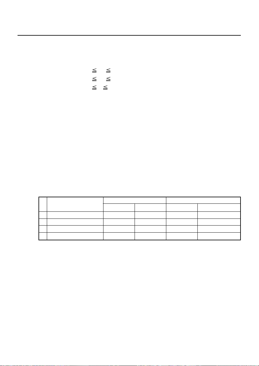
GS H n
[Function] Selecting of printing position of HRI characters
[Code] <1D>H<48>H<n>
[Range] 0
[Outline] Selecting printing position of HRI characters in printing
[Caution] • The HRI characters refer to the bar code-turned characters so
[Default] n = 0
[See Also] GS f, GS k
[Sample Program]
n 3
48
n 51
bar codes.
• “n” means the followings.
n Printing Position
0,48 No printing
1,49 Above the bar code
2,50 Below the bar code
3,51 Both above and below the bar code
that you can read them.
• The HRI characters are printed in the font selected with GS f.
• Specify before the GS k command.
LPRINT CHR$(&H1B) + “3” + CHR$(5);
LPRINT CHR$(&H1D) + “h” + CHR$(50);
LPRINT CHR$(&H1D) + “H” + CHR$(0);
GOSUB BC
LPRINT CHR$(&H1D) + “H” + CHR$(1);
GOSUB BC
LPRINT CHR$(&H1D) + “H” + CHR$(2);
GOSUB BC
LPRINT CHR$(&H1D) + “H” + CHR$(3);
GOSUB BC
END
BC:
LPRINT CHR$(&H1D) + “k”;
LPRINT CHR$(4);
LPRINT “12” + CHR$(0);
LPRINT CHR$(&HA);
RETURN
— 63 —

[Print Results]
No HRI characters
Printed above
Printed below
Printed above and below
— 64 —
GS I n
[Function] Sending the printer ID
[Code] <1D>H<49>H<n>
[Range] 1
[Outline] Sends the specified printer ID.
[Caution] • Under DTR/DSR control, the printer sends the printer ID after verifying
n 3 49 n 51
n Type of printer ID Specification Value (Hex.)
1,49 Model ID CBM1000 30
2,50 Type ID Refer to table “Type ID” below
3,51 ROM version ID As per ROM version
Type ID If n=2, 50 is specified:
Bit Meaning Hex. Decimal
0 Equipped for 2 byte code support 01 1
1 Equipped with autocutter 02 2
Thermosensitive paper Label —
2
Label paper(when "Label" is selected)
3 Undefined — —
4 Unused 00 0
5 Undefined — —
6 Undefined — —
7 Unused 00 0
—
—
—
that the host is ready to receive. If the host is not ready to receive, the
printer waits for the host to become ready to receive.
• Under XON/XOFF control, the printer sends the printer ID without
checking whether the host is ready to receive or busy.
• Because this command is executed when data is mapped in the receive
buffer, there may be a delay between command r eceiving and printer
ID sending depending on the condition of the receive buffer.
• If ASB (Automatic Status Back) is enabled by GS a, the host must
discriminate between the printer ID due to this command and the
status due to ASB.
— 65 —
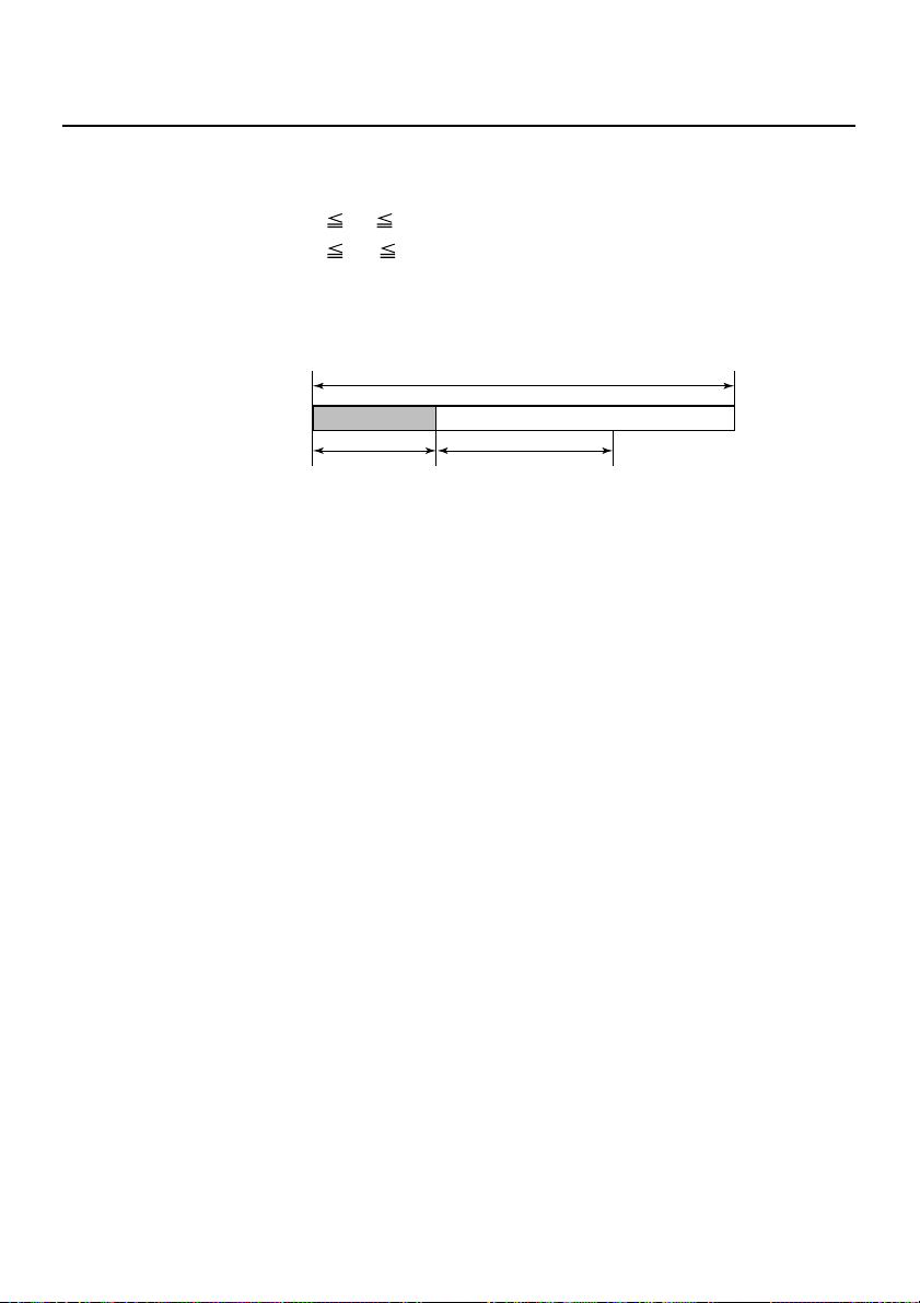
GS L nL nH
[Function] Setting the left margin
[Code] <1D>H<4C>H<nL><nH>
[Range] 0
[Outline] This command sets the left margin specified by nL and nH. The
nL 255
0
nH 255
value of the left margin is [(nL + nH × 256) × basic calculation
pitch] inches.
Printable Area
Left Margin
Print Area Width
[Caution] • This command only works when it is entered at the beginning
of a line.
• When PAGE MODE is selected, this command only executes
the internal flagging of the printer.
• The setting of this command does not affect PAGE MODE.
• The maximum settable left margin is equal to the horizontal
printable area. A setting greater than this maximum is trimmed
to the maximum.
• The basic calculation pitch is defined by GS P. Once defined,
the left margin is not changed if the basic calculation pitch is
changed by GS P.
• The left margin is calculated with the horizontal basic
calculation pitch (x) set by GS P. A fraction resulting from the
calculation is corrected with the minimum pitch of the
mechanism, and the remainder is omitted.
• When mapping character data, if the print area specified is
not wide enough to accommodate one character of the current
font, only the line for that character data is handled as follows:
(1) The print area is extended toward the right to be equivalent
to one character of the current font, but not wider than the
printable area.
(2) If an area for one character cannot be provided as a result
of step (1), the print area is extended toward the left. (So,
the left margin is decreased.)
— 66 —

• When mapping non-character data (Bit image, downloaded
bit image, or bar code), if the print area specified is narrower
than 9-bits, only the line for that data is handled as follows:
(1) The print area is extended toward the left (So, the left
margin is decreased) until it is 9-dot wide, but not wider
than the printable area.
[Default] nL = 0, nH = 0
[See Also] GS P, GS W
— 67 —

GS P x y
[Function] Specifying the basic calculation pitch
[Code] <1D>H<50>H<x><y>
[Range] 0
[Outline] This command sets the horizontal basic calculation pitch to
[Caution] • The horizontal direction is defined as the direction
[Default] x = 203, y = 360
[See Also] ESC SP, ESC $, ESC 3, ESC J, ESC W, ESC \, GS $, GS L, GS W,
x 255
y 255
0
approx. 25.4/x mm (1/x inches), and the vertical basic calculation
pitch to approx. 25.4/y mm (1/y inches).
• If x = 0, the horizontal basic calculation pitch is reverted to the
default value.
• If y = 0, the vertical basic calculation pitch is reverted to the
default value.
perpendicular to the paper feed, and the vertical direction is
defined as the paper feed direction.
• In STANDARD MODE, the following parameters are used
regardless of the character orientation (e.g. inverted or 90°right-turned).
(1) Commands using x: ESC SP, ESC $, ESC \, GS L,
GS W
(2) Commands using y: ESC 3, ESC J
• In PAGE MODE, the parameters used depend on the character
orientation, as follows:
(1) If the start point specified by ESC T is the top left or bottom
right (The characters are mapped in the direction
perpendicular to the paper feed):
• Commands using x: ESC SP, ESC $, ESC W, ESC \
• Commands using y: ESC 3, ESC J, ESC W, GS $,GS \
(2) If the start point specified by ESC T is the top right or bottom
left (The characters are mapped in the paper feed direction):
• Commands using x: ESC 3, ESC J, ESC W, GS $,GS \
• Commands using y: ESC SP, ESC $, ESC W, ESC \
• This command does not affect any other values that are
already set.
• If calculations made in combination with another command
generate fractions, the fractions are corrected with the
minimum pitch of the mechanism, and the remainder is
omitted.
GS \
— 68 —

GS R 0 n
[Function] Collecting receipts
[Code] <1D>H<53>H<30>H<n>H
[Range] n=0
[Outline] • This command is valid only when the collection function of
the DIP switch is enabled.
• This command is ignored in any of the following cases.
(1) There is no paper in the presenter.
The state where no eject command is received or receipt
has already been removed.
(2) A command related to the next printing has been received.
The state where a command related to the next printing
has already been received.
[Caution] This command is ignored when the collection function of the
DIP switch is disabled.
[See Also] GS R 1 n
— 69 —

GS R 1 n
[Function] Setting receipt collection timer
[Code] <1D>H<53>H<31>H<n>
[Range] 0
[Outline] • This command is valid only when the collection function of
[Caution] This command is ignored when the collecting function of the
[Default] n=0
[See Also] GS R 0 n
n 9
the DIP switch is enabled.
• This command sets the wait time till the receipts are collected
automatically.
• If n=1 to 9, n × 2.5 sec is set. If n=0, receipts are not collected
automatically.
• This command is ignored in any of the following cases.
(1) There is no paper in the presenter.
The state where no eject command is received or receipt
has already been removed.
(2) A command related to the next printing has been received.
The state where a command related to the next printing
has already been received.
DIP switch is disabled.
— 70 —

GS S
[Function] Detecting a black mark
[Code] <1D>H<53>H
[Outline] • This command is valid only when a black mark is set in the
paper selection with DIP switch.
• Entering this command allows detection of a black mark.
• When a black mark is detected, the print paper is cut and
ejected.
• Also at the time of printer power on, a black mark is detected
and the print paper is cut and ejected. (Settable with DIP switch)
• If the 18-in. black mark cannot be detected, a mark detection
error occurs, causing BUSY and FAULT to be generated while
cutting and ejecting the print paper.
[Caution] This command is ignored when normal thermal paper is set in
the paper selection with DIP switch.
— 71 —

GS V m ......... (1)
GS V m n ..... (2)
[Function] Cutting the paper
[Code] (1) <1D>H<56>H<m>
(2) <1D>H<56>H<m><n>
[Range] (1) m = 0, 1, 48, 49
(2) m = 65, 66
0
n 255
[Outline] Performs the specified paper cutting.
m Function
0,1,48,49 Paper cut (full cut) (Leaving a bridge area uncut)
65,66
[Caution] • Fully cut for the label sheet specs.
• In STANDARD MODE, this command only works when it is
entered at the beginning of a line.
For (1):
• A partial cut (Leaving a bridge area uncut) is executed.
For (2):
• If n = 0, the paper is fed to the cut position, and then cut. If n
≠ 0, the paper is fed by “n × basic calculation pitch” inches
past the cut position, and then cut.
• The basic calculation pitch is set by GS P.
The paper feed amount is calculated with the vertical basic
calculation pitch (y).
A fraction resulting from the calculation is corrected with the
minimum pitch of the mechanism, and the remainder is
omitted.
Paper feed by “cut position + {n × basic calculation
pitch}”and paper cut (full cut) (Leaving a bridge area uncut)
— 72 —
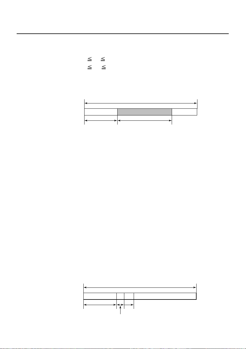
GS W nL nH
[Function] Setting the print area width
[Code] <1D>H<57>H<nL><nH>
[Range] 0
[Outline] Sets the print area width specified by nL and nH.
[Caution] • This command only works when it is entered at the beginning
nL 255
0
nH 255
• The print area width will be [(nL + nH × 256) × basic calculation
pitch] inches.
Printable Area
Print Area WidthLeft Margin
of a line.
• When PAGE MODE is selected, this command only executes
the internal flagging of the printer.
• The setting of this command does not affect PAGE MODE.
• If the value entered with this command exceeds the printable
area for one line, the entire area except the left margin is set
as the print area width.
• The basic calculation pitches are defined by GS P. Once
defined, the print area width is not changed if the basic
calculation pitch is changed by GS P.
• The print area width is calculated with the horizontal basic
calculation pitch (x) defined by GS P. A fraction resulting from
the calculation is corrected with the minimum pitch of the
mechanism, and the remainder is omitted.
• If the first character to be mapped at the beginning of a line
has a width (Including the right spacing) greater than the print
area width, only that line is handled as follows:
(1) The print area is extended toward the right to accommodate
the first character, but not wider than the printable area.
Left Margin
Printable Area
A
Extended toward the right
Print Area Width
— 73 —

(2) If a sufficient area cannot be provided as a result of step
(1), the print area is extended toward the left (So, the left
margin is decreased).
Printable Area
(1)
Extended
toward
the right
Left Margin
(2)The left margin
is trimmed
A
Print Area Width
(3) If a sufficient area cannot be provided as a result of step
(2), the right spacing is trimmed.
• When mapping a bit image (Or downloaded bit image), if the
print area is narrower than the minimum width of the bit image
(Two dots for single density, or one dot for double density),
only the line for that image is handled as follows:
(1) The print area is extended toward the left (So, the left
margin is decreased) until it is equal to the minimum width
of the image, but not wider than the printable area.
[Default] nL=64, nH=2 (When 58mm wide paper is used: nL=176, nH=1)
Since the default value varies depending on the number of
columns, refer to “Defing the print area in PAGE MODE; ESC
W”on page 44, for more information.
[See Also] GS L, GS P
— 74 —

GS \ nL nH
[Function] Specifying the relative vertical position of a character in
PAGE MODE
[Code] <1D>H<5C>H<nL><nH>
[Range] 0
[Outline] This command is used in PAGE MODE to specify the vertical
[Caution] • This command is ignored when PAGE MODE is not selected.
nL 255
0
nH 255
position of a character in the data mapping start position, in a
relative position with respect to the current position. The next
data mapping start position will be at a point [(nL + nH × 256)×
basic calculation pitch] inches away from the current position.
• If a new position is specified for a character located beneath
the current position, it should be specified as positive (+). If it
is above the current position, it should be negative (-).
• A negative value is the complement of 65536. For example, to
move the position by N pitches up, specify it as:
nL + nH × 256 = 65536 - N
• The specification of a relative position outside the specified
print area is ignored.
• Depending on the start point specified by ESC T , this command
acts as follows:
(1) If the start point is the top left or bottom right, the command
specifies the relative position in the paper feed direction
(The character’s top-bottom direction) using the vertical
basic calculation pitch (y).
(2) If the start point is the top right or bottom left, the command
specifies the relative position in the direction perpendicular
to the paper feed (The character’s top-bottom direction)
using the horizontal basic calculation pitch (x).
• The basic calculation pitch is set by GS P.
• Fractions resulting from calculations are corrected with the
minimum pitch of the mechanism, and the remainder is
omitted.
— 75 —

GS ^ n1 n2 n3
[Function] Executing the macro
[Code] <1D>H<5E>H<n1><n2><n3>
[Range] 0
[Outline] Executing contents defined in macro.
[Caution] • When this command is received while in macro definition,
[Default] The initial value is not defined.
[See Also] GS :
[Sample Program] Refer to Sample Program and Print Results for GS: on page 62.
n1 255
0
n2 255
0
n3 1
n1 : The number of times of macro execution
n2 : Waiting time on macro execution
Waiting time of n2 × 100 msec is given for every execution.
n3 : Macro execution mode
n3=0 Continuous execution:
The Macro is executed “n1” times continuously at the
time interval specified by “n2”.
n3=1 Execution by FEED Switch:
After waiting for the time specified by “n2”, the
ARARM LED flickers and the FEED switch is waiting to
be pressed. When it is pressed, the macro is executed
once. This action is repeated “n1” times.
suspension of macro definition is indicated. At this time, the
defined content is cleared.
• No execution takes place when the macro is held undefined
or n1=0.
• While in macro execution with n3=1, paper feed with the FEED
switch is not available.
— 76 —

GS a n
[Function] Enabling/Disabling ASB (Automatic Status Back)
[Code] <1D>H<61>H<n>
[Range] 0
[Outline] This command selects the status item to be addressed by ASB
[Caution] • If any status item is enabled, the status is sent to the host
n 255
(Automatic Status Back.)
Bit Status item addressed by ASB Hex. Decimal
0 Undefined ——
Online/offline status = disabled 00 0
1
Online/offline status = enabled 02 2
Error status = disabled 00 0
2
Error status = enabled 04 4
Continuous Paper Sensor = disabled 00 0
3
Continuous Paper Sensor = enabled 08 8
4 Undefined ——
5 Undefined ——
6 Undefined ——
7 Undefined ——
when this command is executed. After that time on, the status
is sent each time an enabled status item changes. Because
each status item represents the current condition, status items
disabled for ASB may also have changed.
• The ASB function is disabled if all status items are disabled.
• If the ASB function is enabled by default, the host receives the
status the first time the printer gets ready for communication
after it is turned on.
• The printer sends 4 bytes of status shown in the tables below,
without checking whether the host is ready to receive or busy.
The 4 bytes of status is a continuous string except for XOFF
code.
• Because this command is executed when data is mapped in
the receive buffer, there may be a delay between command
receiving and status sending depending on the condition of
the receive buffer.
• Even if the printer is excluded from the selection of peripheral
equipment (ESC =), the 4 bytes of status is sent to the host
whenever status changes.
• When DLE EOT , GS I, or GS r is used, the host must discriminate
between the status specified by these commands and the
status due to ASB.
— 77 —
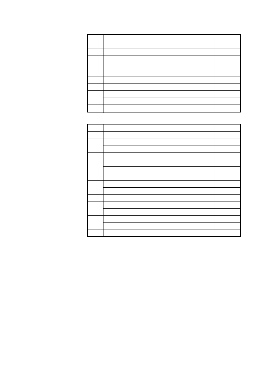
(1) 1st byte (Printer information)
Bit Status Hex. Decimal
0 Unused 00 0
1 Unused 00 0
2 Unused 00 0
Online status 00 0
3
Offline status 08 8
4 Unused 10 16
5 Unused 00 0
Not in paper feed state triggered by FEED switch
6
In paper feed state triggered by FEED switch
7 Unused 00 0
00 0
40 64
(2) 2nd byte (Error occurrence information)
Bit Status Hex. Decimal
0 Undefined — —
Paper not jammed in Presenter 00 0
1
Paper jammed in Presenter 02 2
No Black mark detection error occurred
(only when “Black mark” is selected).
2
A Black mark detection error occurred
(only when “Black mark” is selected).
Auto cutter error not occurred 00 0
3
Auto cutter error occurred 08 8
4 Unused 00 0
Unrecoverable error not occurred 00 0
5
Unrecoverable error occurred 20 32
Auto recovery error not occurred 00 0
6
Auto recovery error occurred 40 64
7 Unused 00 0
00 0
04 4
Bit 1: If this error occurs due to paper jam, etc., remove the cause
of the error and press the FEED switch to return to the
normal condition. If this error is caused by the deficiency
of a circuit (disconnection, etc.), pressing the FEED switch
cannot recover the normal operation.
— 78 —

(3) 3rd byte (Paper Sensor information)
Bit Status Hex. Decimal
Paper found by Paper Near-end Sensor 1
0
Paper not found by Paper Near-end Sensor 1
Paper found by Paper Near-end Sensor 2
1
Paper not found by Paper Near-end Sensor 2
Paper found by Paper-end Sensor 00 0
2
Paper not found by Paper-end Sensor 04 4
Paper found by Presenter Sensor 00 0
3
Paper not found by Presenter Sensor 08 8
4 Unused 00 0
5 Undefined — —
6 Undefined — —
7 Unused 00 0
00 0
01 1
00 0
02 2
(4) 4th byte (Paper Sensor information)
Bit Status Hex Decimal
0 Undefined — —
1 Undefined — —
2 Undefined — —
3 Undefined — —
4 Unused 00 0
5 Undefined — —
6 Undefined — —
7 Unused 00 0
[Default] n = 0
[See Also] DLE EOT, GS r
— 79 —

GS f n
[Function] Selecting the font of HRI characters
[Code] <1D>H<66>H<n>
[Range] n = 0, 1
[Outline] Selecting the font of HRI characters in printing bar code.
The type of font can be selected with “n” as follows:
n Font
0, 48 Font A (12 × 24)
1, 49 Font B (9 × 24)
The HRI characters refer to the bar code-turned characters so
that you can read them.
[Caution] The HRI characters are printed at the position specified with
GS H.
[Default] n = 0
[See Also] GS H
[Sample Program]
[Print Results]
LPRINT CHR$(&H1D) + “h” + CHR$(50);
LPRINT CHR$(&H1D) + “H” + CHR$(2);
LPRINT CHR$(&H1D) + “f” + CHR$(0);
GOSUB BC
LPRINT CHR$(&H1D) + “f” + CHR$(1);
GOSUB BC
END
BC:
LPRINT CHR$(&H1D) + “k”;
LPRINT CHR$(4);
LPRINT “12” + CHR$(0);
LPRINT CHR$(&HA);
RETURN
— 80 —
← FONT A
← FONT B

GS h n
[Function] Specifying the height of the bar code
[Code] <1D>H<68>H<n>
[Range] 1
[Outline] Selecting bar code height.
[Default] n = 162
[Sample Program] Refer to Sample Program and Print Results for GS w on
n 255
“n” denotes the number of dots in the vertical direction.
page 93.
— 81 —

GS k m [d1 ..... dk] NUL
GS k m n [d1 ...... dn]
[Function] Printing the bar code
[Code] (1) <1D>H<6B>H<m> [d1.....dk] NUL
(2) <1D>H<6B>H<m><n> [d1....dn]
[Range] (1) 0
[Outline] Selects a bar code system and prints the bar code.
m 6 The definitions of “k” and “d” vary with the
bar code system.
(2) 65
m 73 The definitions of “n” and “d” vary with the
bar code system.
For (1):
m Bar code system Range of “n” Range of “d”
0 UPC-A 11 k 12 48 d 57
1 UPC-E 11 k 12 48 d 57
2 JAN13 (EAN) 12 k 13 48 d 57
3 JAN8 (EAN) 7 k 8 48 d 57
4 CODE39 1 k
5 ITF
6 CODABAR 1 k
1 k (Must be 48 d 57
an even number)
48 d 57, 65 d 90
32, 36, 37, 43, 45, 46, 47
48 d 57, 65 d 68
36, 43, 45, 46, 47, 58
For (2):
m Bar code system Range of “n” Range of “d”
65 UPC-A 11 n 12 48 d 57
66 UPC-E 11 n 12 48 d 57
67 JAN13 (EAN) 12 n 13 48 d 57
68 JAN8 (EAN) 7 n 8 48 d 57
69 CODE39 1 n 255
70 ITF
71 CODABAR 1 n 255
72 CODE93 1 n 255 0 d 127
73 CODE128 2 n 255 0 d 127
1 n 255 (An
even number)
48 d 57, 65 d 90
32, 36, 37, 43, 45, 46, 47
48 d 57
48 d 57, 65 d 68
36, 43, 45, 46, 47, 58
— 82 —

[Caution] For (1):
• This command ends with a NUL code.
• For UPC-A or UPC-E, the bar code is printed when 12 bytes of
bar code data have been entered, and the subsequent data is
handled as normal data.
• For JAN13, the bar code is printed when 13 bytes of bar code
data have been entered, and the subsequent data is handled
as normal data.
• For JAN8, the bar code is printed when 8 bytes of bar code
data have been entered, and the subsequent data is handled
as normal data.
• The data of ITF bar code must have an even number of
columns. Should the data have an odd number of columns,
the last column is ignored.
For (2):
• Numeral “n” indicates the number of data items, and the
subsequent “n” bytes of data are handled as bar code data.
• If “n” is out of the range, the processing of the command is
aborted, and the subsequent data is handled as normal data.
For STANDARD MODE:
• If “d” is out of the range, only a paper feed is executed, and
the subsequent data is handled as normal data.
• If the bar code is wider than the print area for one line, the bar
code is not printed, but only a paper feed is executed.
• The amount of paper feed corresponds to the height of the
bar code (Including the HRI characters if HRI character printing
is specified), irrespective of the line feed width set by a
command such as ESC 2 or ESC 3.
• This command only works if no data exists in the print buffer.
If any data exists in the print buffer, the data subsequent to
“m” is handled as normal data.
• After the bar code is printed, the beginning of the line is taken
as the start position for the next print.
• This command is not affected by any print modes (Emphasis,
double strike, underline, and character size), except for the
inverted character mode.
— 83 —

For PAGE MODE:
• This command only maps the bar code, without performing a
printout. After the bar code is mapped, the dot next to the last
data item of the bar code is taken as the start position for the
next data mapping.
• If “d” is out of the range, the processing of the command is
aborted, and the subsequent data is handled as normal data.
In this case, the data mapping start position does not move.
• If the bar code is wider than the print area, the bar code is not
printed, but the data mapping start position is moved to the
left end of the non-print area.
[Default] The initial value is not defined.
— 84 —

[Description of Bar Codes]
<For print examples, refer to page 88.>
UPC-A This bar code, consisting of numerals only, has a
UPC-E This bar code, consisting of numerals only, has
JAN-13(EAN) This bar code, consisting of numerals only, has a
JAN-8(EAN) This bar code, consisting of numerals only, has a
CODE39 This bar code, consisting of upper -case alphabetic
ITF This bar code, consisting of only numerals, has a
fixed length of 12 columns; a 11-column number
entered from the host or application software plus
a check digit (12th column) automatically
calculated inside the printer. If the 12th-column
numeral is sent from the host, the entire bar code
will be printed as it is.
a fixed length of 8 columns; the first number
system character is “0” stationary. A 12-column
numeral entered from the host or application
software is compressed to 8 columns with a check
digit attached and then is printed. The 12thcolumn check digit is automatically calculated
inside the printer. If it is and sent from the host,
the entire bar code will be printed, compressed
to 8 columns.
fixed length of 13 columns; a 12-column number
entered from the host or application software plus
a check digit (13th column) automatically
calculated inside the printer. If the 13th-column
numeral is sent from the host, the entire bar code
will be printed as it is.
fixed length of 8 columns; a 7-column number
entered from the host or application software plus
a check digit (8th column) automatically
calculated inside the printer. If the 8th-column
numeral is sent from the host, the entire bar code
will be printed as it is.
characters and numerals, has a variable length
of columns. The start/stop code “∗” is
automatically added by the printer. The available
characters include space and “$ % + –
•
/ 0 1 2 3 4
5 6 7 8 9” and upper-case alphabetic characters.
variable length of even-number columns. If a code
of odd-number columns is sent, the bar code will
not be printed.
— 85 —

CODABAR (NW-7)
This bar code, consisting of alphanumerics, has
a variable length of columns. Available characters
include “0 1 2 3 4 5 6 7 8 9 A B C D $ + – . / :”. A
start/stop code is required; any one of A, B, C,
and D is used.
CODE93 This bar code, consisting of alphanumeric and
control characters, has a variable length of
columns. The HRI character string is preceded and
followed by a “■” character. HRI characters for
control characters (00H - 1FH, and 7FH) are each
printed as a combination of a “■” character and
an alphabetic character.
Control character
ASCII Hex. ASCII Hex.
NUL 00 ■ U DLE 10 ■ P
SOH 01 ■ A DC1 11 ■ Q
STX 02 ■ B DC2 12 ■ R
ETX 03 ■ C DC3 13 ■ S
EOT 04 ■ D DC4 14 ■ T
ENQ 05 ■ E NAK 15 ■ U
ACK 06 ■ F SYN 16 ■ V
BEL 07 ■ G ETB 17 ■ W
BS 08 ■ H CAN 18 ■ X
HT 09 ■ IEM19■ Y
LF 0A ■ J SUB 1A ■ Z
VT 0B ■ K ESC 1B ■ A
FF 0C ■ LFS1C■ B
CR 0D ■ MGS1D■ C
SO 0E ■ NRS1E■ D
SI 0F ■ 0US1F■ E
HRI character
Control character
DEL 7F ■ T
HRI character
— 86 —

CODE128 This bar code consists of 103 bar code characters
and three code sets, enabling 128 ASCII code
characters to be printed. It has a variable length
of columns.
• Code set A ASCII characters 00H - 5FH can be
represented.
• Code set B ASCII characters 20H - 7FH can be
represented.
• Code set C Two-digit numbers 00 - 99 can each
be represented by one character.
In addition to the above characters, special
characters are available:
• Shift character (SHIFT)
When used in code set A, one character next to a
Shift character is treated as a character of code
set B. When used in code set B, one character
next to a Shift character is treated as a character
of code set A. The Shift character cannot be used
in code set C.
• Code set select characters (CODE A, CODE B,
CODE C):
The code set following a code set select character
is switched to code set A, B, or C.
• Function characters (FNC1, FNC2, FNC3, FNC4):
How the function characters are used depends
on each application. In code set C, only FNC1 is
available.
When sending print data, note these points:
(1) Each string of bar code data must begin with a code set
select character (CODE A, CODE B, or CODE C), which selects
the first code set to use.
(2) Every special character is specified by a combination of two
characters: a brace “{” followed by one character. A brace
“{” itself is sent twice consecutively.
— 87 —

[Sample Program]
Special characters
Hex. ASCII
7B53 { S SHIFT SHIFT –N/A
7B41 { A –N/A CODE A CODE A
7B42 { B CODE B –N/A CODE B
7B43 { C CODE C CODE C –N/A
7B31 { 1 FNC1 FNC1 FNC1
7B32 { 2 FNC2 FNC2 –N/A
7B33 { 3 FNC3 FNC3 –N/A
7B34 { 4 FNC4 FNC4 –N/A
7B7B { { ‘ { ‘ ‘ { ‘ ‘ { ‘
Code set A Code set B Code set C
<Example>
To print “No.” in code set B, followed by “123456” in code
set C, send the following data string:
GS k <73><10><7Bh 42h> “No.” <7Bh 43h><12><34><56>
• If the printer finds a string of bar code data that does not begin
with a code set select character, it immediately aborts the
command processing and handles the subsequent data as
normal data.
• If the printer received a character that is not available in the
currently selected code set, it immediately aborts the command
processing and handles the subsequent data as normal data.
• An HRI character corresponding to either a Shift character or
a code select character is not printed. An HRI character for
either a function character or a control character is treated as
a space character.
LPRINT CHR$(&H1D) + “H” + CHR$(2);
LPRINT CHR$(&H1D) + “k”;
LPRINT CHR$(4);
LPRINT “123” + CHR$(0);
END
[Print Results]
When the data “123” is printed with the code 39
— 88 —

[Description of Bar Codes]
UPC-A, UPC-E, JAN-13 (EAN), JAN-8 (EAN), CODE39, ITF,
CODABAR, CODE93, CODE128
Type Print Sample Outline of Symbol
UPC-A
12-column fixed-length bar code
consisting of numerals only.
UPC-E
JAN-13
JAN-8
CODE39
ITF
CODABAR
(NW-7)
CODE93
8-column fixed-length bar code
consisting of numerals only.
Abbreviated version of UPC-A.
13-column fixed-length bar code
consisting of numerals only.
8-column fixed-length bar code
consisting of numerals only.
Variable-length bar code consisting
of alphabetic characters and
numerals. The start/stop code “∗”is
automatically added.
Even-column variable-length bar
code consisting of numerals only.
Variable-length bar code consisting
of alphanumeric characters. Any one
of A, B, C, and D is required as the
start/stop code.
Variable-length bar code consisting
of alphanumeric and control
characters.
CODE128
Variable-length bar code consisting
of any of 128 ASCII code characters.
Printing is done according to bar code type, number of print
columns, bar code height, width (Magnification), availability of
HRI character, and bar code data.
— 89 —

GS r n
[Function] Sending status
[Code] <1D>H<72>H<n>
[Range] n=1, 49
[Outline] Sends the specified status to the host.
n Function
1,49 Sends the paper Sensor status.
[Caution] • When the serial interface is used:
For DTR/DSR control:
The printer sends the status after verifying that the host is
ready to receive. If the host is not ready to receive, the
printer waits for the host to become ready to receive.
For XON/XOFF control:
The printer sends the status without checking whether the
host is ready to receive or busy.
• Because this command is executed when data is mapped in
the receive buffer, there may be a delay between receiving the
command and sending the status depending on the condition
of the receive buffer.
• If ASB (Automatic Status Back) is enabled by GS a, the host
must discriminate between the status due to this command
and the status due to ASB.
• Paper Sensor status (n = 1, 49)
Bit Status Hex. Decimal
Paper found by Paper Near-end Sensor 1
0
Paper not found by Paper Near-end Sensor 1
Paper found by Paper Near-end Sensor 2
1
Paper not found by Paper Near-end Sensor 2
Paper found by Paper-end Sensor 00 0
2
Paper not found by Paper-end Sensor (04) (4)
Paper found by Presenter Sensor 00 0
3
Paper not found by Presenter Sensor 08 8
4 Unused 00 0
5 Undefined — —
6 Undefined — —
7 Unused 00 0
Bit 2: Whenever the Paper-end Sensor detects a “paper out”
state, the printer goes offline, and the command is not
executed. The printer, therefore, never sends a status bit
2 = “1”.
[See Also] DLE EOT, GS a
— 90 —
00 0
01 1
00 0
02 2

GS v 0 m xL xH yL yH d1...dk
[Function] Printing of raster bit image
[Code] <1D>H<76>H<30>H<m><xL><xH><yL><yH> [<d>] k
[Range] 0
[Outline] Prints raster bit images in mode “m”.
[Details] • In STANDARD MODE, this command is valid only when ther e
m 3, 48 m 51, 0 xL 255, 0 xH 255,
0
yL 255, 0 yH 8, 0 d 255,
k=(xL+xH × 256) × (yL+yH × 256), however, k≠0
m Mode Name
0,48
1,49
2,50
3,51
NORMAL MODE
DOUBLE WIDTH MODE
DOUBLE HEIGHT MODE
QUADRUPLE SIZE MODE
Dot Density in Dot Density in
Vertical Direction
203 DPI 203 DPI
203 DPI 101 DPI
101 DPI 203 DPI
101 DPI 101 DPI
Horizontal Direction
• xL, xH specify the number of data in horizontal direction of
the bit image to (xL+xH × 256) bytes.
• yL, yH specify the number of data in vertical direction of the
bit image to (yL+yH × 256) bytes.
is no print data in the print buffer.
• Any of the print modes (Character size, emphasis, double strike,
inverting, underlining, back-to-white reversing, etc.) does not
affect the raster bit image.
• If the print area specified by GS L and GS W is narrower than
a minimum width, the print area for that line only is extended
to the minimum width. The minimum width is one dot in
NORMAL MODE (m=0, 48) and DOUBLE HEIGHT MODE (m=2,
50), and 2 dot in DOUBLE WIDTH MODE (m=1, 49) and
QUADRUPLE SIZE MODE (m=3, 51).
• Any part of data that is out of the print area is only read and
discarded in units of dot.
• The print start position can arbitrarily be specified with HT
(Horizontal tab), ESC $ (Specifying absolute position), ESC \
(Specifying relative positions), and GS L (Setting left margins).
Note that if the print start position is not a multiple of 8, the
printing speed may decrease.
• The setting of ESC a (Aligning characters) are also valid for
the raster bit image.
— 91 —

[Example]
• If this command is executed during macro definition, the macro
definition is suspended, and the processing of the command
starts. The macro is left undefined.
• “d” denotes defined data. Dots to be printed are specified as
“1”, and those not to be printed as “0”.
When xL+xH × 256= 64
(xL+xH × 256) × 8 dot = 512 dot
123 62
65 66 67
7
6 5 4 3 2 1 0
MSB
126
k-2
LSB
63 64
127
k-1
128
k
yL+yH × 256 dot
— 92 —

GS w n
[Function] Specifying the horizontal size (Magnification) of bar code
[Code] <1D>H<77>H<n>
[Range] 2
[Outline] Selecting bar code width.
[Default] n = 3
[Sample Program]
n 6
“n” denotes the number of dots in fine element width.
LPRINT CHR$(&H1D) + “h” + CHR$(30);
LPRINT CHR$(&H1D) + “w” + CHR$(2);
GOSUB BC
LPRINT CHR$(&H1D) + “h” + CHR$(50);
LPRINT CHR$(&H1D) + “w” + CHR$(3);
GOSUB BC
LPRINT CHR$(&H1D) + “h” + CHR$(80);
LPRINT CHR$(&H1D) + “w” + CHR$(4);
GOSUB BC
END
BC:
LPRINT CHR$(&H1D) + “k”;
LPRINT CHR$(4);
LPRINT “12” + CHR$(0);
RETURN
[Print Results]
— 93 —
← Height = 30, Magnification = 2
← Height = 50,
← Height = 80,
Magnification = 3
Magnification = 4

FS g3 m a1 a2 a3 a4 nL nH d1…dk
[Function] Writing data into the download user NV memory
[Code] <1C>H<67>H<33>H<m>H<a1>H<a2>H<a3>H<a4>H
<nL>H<nH>H[<d>]nL+(nH × 256)
[Range] m=0
6000H
Sto rage start address
k=(nL+(nH × 256))
[Outline] This command loads data into the download user NV memory .
•“m” is fixed at 0.
• a1, a2, a3, a4 set the data storage start address at (a1+(a2 ×
• nL, nH sets the number of stored data to (nL+(nH × 256)) bytes.
•“d” denotes the data to be stored.
[Details] • The download user NV memory refers to a storage area
• When the STANDARD MODE is selected, this command is valid
• This command is invalid when PAGE MODE is selected.
• If this command is sent while a macro is being defined, the
• If the argument (m), the storage start address (a1, a2, a3, a4),
• Date storage processing causes “overwriting” to be executed,
• When an error occurs during the writing process, the error
• Data in the user NV memory can be read by using the FS g4
• Data in the user NV memory is not initialized by using the ESC
(a1+(a2 × 256)+(a3 × 65536)+(a4 × 16777216)) 7FFFH
(nL+(nH × 256)) 1024
256)+(a3 × 65536)+(a4 × 16777216)).
exclusively for character data secured on non-volatile memory.
Font A: Start address 6000H End address 71FFH (36 bytes for
1 character)
Font B: Start address 7200H End address 7F7FH (27 bytes for
1 character)
only when it is written at the head of the line.
definition process will be stopped and the execution of this
command will start.
or the number of stored data (nL, nH) is outside the definition
area, this command becomes invalid and the following data
will be processed as normal data.
thus erasing the data stored already before the storage
processing was executed.
will be a “Memory or gate-array R/W error”.
command.
@ command, the FS q command or by resetting the printer or
turning the power off.
— 94 —

[Caution] • Because frequent writing in the non-volatile memory can
destroy the memory, the writing command (FS g3) should be
used less than 10 times a day.
• It may happen that the printer becomes BUSY during the
process of writing data into the non-volatile memory while
this command is executed. When the printer becomes BUSY,
it will stop receiving data. Therefore, sending data from the
host (Including real time commands) is prohibited.
[Reference] FS g4
— 95 —
FS g4 m a1 a2 a3 a4 nL nH
[Function] Reading data from the download user NV memory
[Code] <1C>H<67>H<34>H<m>H<a1>H<a2>H<a3>H<a4>H
<nL>H<nH>H
[Range] m=0
6000H
Write start address +n1+nH × 256
K=(nL+(nH × 256))
[Outline] • This command reads data from the download user NV
•“m” is fixed at 0.
• a1, a2, a3, a4 set the data sending start address at (a1+(a2 ×
• nL, nH set the number of sent data to (nL+(nH × 256)) bytes.
[Details] • The download user NV memory refers to a storage area
• If the argument (m), the send start address (a1, a2, a3, a4), or
• When the preparation for sending data is completed, the
• When the DTR/DSR control is selected, all codes are sent
(a1+(a2 × 256)+(a3 × 65536)+(a4 × 16777216)) 7FFFH
8000H
memory.
256)+(a3 × 65536)+(a4 × 16777216)).
exclusively for character data secured on non-volatile memory.
Font A: Start address 6000H End address 71FFH (36 bytes for
1 character)
Font B:Start address 7200H End address 7F7FH (27 bytes for
1 character)
the number of sent data (nL, nH) is outside the definition area,
this command becomes invalid and the following data will be
processed as normal data.
following processes are executed.
1) The printer state will change from READY to BUSY. If the
printer state is already set to BUSY, the printer will do
nothing.
2) (Header + data + NUL) is sent.
3) The printer state will change from BUSY to READY. At this
moment, if the printer state is set to BUSY because of other
reasons, it remains in the BUSY state.
The construction of (Header + data + NUL) is as follows.
Header:5FH in hexadecimal = 95 in decimal (1 byte)
Data: data in download user NV memory ((nL+nH × 256)
bytes)
continuously after verifying that the host can receive the data
to be sent. If the host cannot receive the data, it will wait until
it can be received.
— 96 —

• When the XON/XOFF control is selected, all the codes are sent
continuously without verifying that the host can receive the
data. Data that has been sent is always continuous except for
the XOFF code.
• When parallel interface is used, the size of the buffer for
sending data (The buffer that stores all data to be sent except
for ASB status) is 99 bytes. Data which exceeds 99 bytes, will
be discarded.
• Data can be written into the download user NV memory using
the FS g3 command.
• There may be a delay between receiving this command and
storing the data depending on the state of the receiving buffer.
[Caution] • After the header is sent, all data will be sent without verifying
whether the host can receive the data or not. Therefore, the
available space in the receiving buffer of the host should be
more than (The number of sent data+2) in order not to lose
data during the execution of this command.
• While data is being sent, real time commands (Commands
with a DLE extension) will be ignored. And even if the ASB
function is validly selected, ASB status will not be sent while
data is in the process of being sent. Therefore, it is not possible
to check the change in the printer state by checking its status.
The user must pay attention to this.
[Reference] FS g3
— 97 —
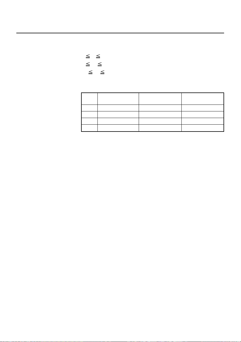
F S p n m
[Function] Printing the download NV bit images
[Code] <1C>H<70>H<n><m>
[Range] 1 n 255
0
m 3
48
m 51
[Outline] This command prints the download NV bit images (n) using a
specified mode (m).
m Mode Name
0,48
1,49
2,50
3,51
•“n” denotes the number of the download bit image.
•“m” denotes the bit image mode.
NORMAL MODE
DOUBLE WIDTH MODE
DOUBLE HEIGHT MODE
QUADRUPLE SIZE MODE
[Details] • The download NV bit image refers to the image that is defined
by the FS q command in the non-volatile memory and printed
by the FS p command.
• When the specified NV bit image “n” is undefined, this
command is invalid.
• When the STANDARD MODE is selected, this command is valid
only when there is no data in the print buffer.
• This command is invalid when PAGE MODE is selected.
• Any printing modes except the upside-down printing mode
(i.e. emphasis, double strike, underlining, character size,
inverted character printing, 90˚ - right-turned) are not affected.
• When the printing area set by the functions GS L and GS W is
not enough for one vertical line of the download NV bit image,
the line alone is dealt with as follows. One vertical line of the
bit image is 1dot in NORMAL MODE (m = 0, 48) and DOUBLE
HEIGHT MODE (m = 2, 50), and it is 2 dots in double WIDTH
MODE (m = 1, 49) and QUADRUPLE SIZE MODE. (m = 3, 51)
1) The printing area is extended to the right side within the
limits of the printing area so that one vertical line of the
download NV bit image can be printed.
2) When a sufficient printing area cannot be maintained even
after executing (1), the printing area is extended to the left
side. (The left margin is reduced.)
Dot Density in Dot Density in
Vertical Direction
203 DPI 203 DPI
203 DPI 101 DPI
101 DPI 203 DPI
101 DPI 101 DPI
Horizontal Direction
— 98 —
 Loading...