

Page 1

Page 2

Table of Contents
Table of Contents
Product Overview ........................................................ 4
Package Contents ...................................................4
System Requirements ............................................. 4
Introduction ..............................................................5
Features ..................................................................6
Hardware Overview ................................................. 7
Hardware Overview ................................................. 8
Hardware Installation ...............................................9
Installation ..................................................................11
Wireless Installation Considerations ...................... 11
Software Installation ..............................................12
Conguration ............................................................. 17
Installation Wizard .................................................17
Setup ...............................................................18
Network Settings .............................................. 19
Wireless Network Settings ...............................20
Upgrade ........................................................... 22
Enabling UPnP for Windows® XP .......................... 23
Testing the DCS-3420 ........................................... 28
Viewing Your DCS-3420 ........................................ 29
Using the DCS-3420 with an Internet Browser ......30
Home .....................................................................31
Connection Type .............................................. 32
Conguration ...................................................33
Advanced ............................................................... 33
Network ............................................................ 33
Wireless ........................................................... 35
Mail & FTP ....................................................... 37
DDNS & UPnP .................................................39
Video ................................................................ 40
Audio ................................................................ 43
Image Setting ................................................... 44
Motion Detection ..............................................45
Tools ......................................................................46
Admin ............................................................... 46
System .............................................................47
Applications .....................................................48
Default .............................................................50
Status ....................................................................51
Device Info .......................................................51
Log ...................................................................52
Help .......................................................................53
Record Snapshots to your FTP server .................. 54
I/O Connector ........................................................58
DI/DO Connection Diagram ...................................59
Adjusting the Camera Focus ................................. 62
Replacing the Lens ................................................63
Reset and Restore ................................................. 64
Installing the IP Surveillance Software .................. 65
Using the IP Surveillance Software ....................... 70
2D-Link DCS-3420 User Manual
Page 3

Table of Contents
Launcher ..........................................................70
Monitor Program .............................................. 74
Playback Program .........................................107
Schedule Video Recording .................................. 118
Wireless Security.....................................................121
What is WEP? .....................................................121
What is WPA? .....................................................122
Setting Security ...................................................123
Using & Conguring the DCS-3420 .....................124
Router Set-Up and Installation ............................128
Troubleshooting ...................................................... 131
Wireless Basics ....................................................... 134
Networking Basics .................................................. 139
Check your IP address ........................................139
Statically Assign an IP address ........................... 140
Technical Specications......................................... 141
Contacting Technical Support ............................... 143
Warranty ...................................................................144
Registration .............................................................. 149
3D-Link DCS-3420 User Manual
Page 4

Section 1 - Product Overview
• D-Link DCS-3420 Wireless Day & Night Internet Camera
• CAT5 Ethernet Cable
• Power Adapter
• Antenna
• Manual and Software on CD
• Quick Install Guide
• Camera Stand
Note: Using a power supply with a different voltage than the one
included with your product will cause damage and void the warranty
for this product.
Product Overview
Package Contents
If any of the above items are missing, please contact your reseller.
System Requirements
• Windows® 2000 or XP
• At least 256MB of memory (512MB recommended)
• An available Ethernet connection
• Internet Explorer 6.x or higher Internet Web Browser
• VGA card resolution: 800x600 or above
• CPU: 1.7GHz or above processor (2.8GHz plus processor with 512MB memory and a 32MB video card
is required for multiple camera viewing and recording in IP surveillance program)
4D-Link DCS-3420 User Manual
Page 5

Section 1 - Product Overview
Introduction
The D-Link SECURICAM Network DCS-3420 Wireless Day & Night Internet Camera is a powerful surveillance system
that connects wirelessly to your 802.11b/g* network. The DCS-3420 differs from a conventional PC Camera because it
is a standalone system with a built-in CPU and Web server, providing a low-cost solution capable of solving demanding
security and home/ofce monitoring needs. It is designed with aluminum casing for maximum heat dissipation and
better protection. Snapshot enables you to save a snapshot image directly from a Web browser to a local hard drive
without installing any software. With 0.5 lux light sensitivity, the DCS-3420 is capable of capturing video in rooms with
minimal lighting. With optional Day & Night Auto iris lens, IR LED Lens or night vision illuminator1, you can customize
your surveillance application to enable low light or night vision video streaming. You can also zoom in on all the action
with the DCS-3420’s 4x digital zoom2 feature. The DCS-3420 gives you the ability to monitor video and audio in your
home/ofce using an Internet browser from any where in the world! Simple installation procedures, along with the built-
in Web-based interface offers easy integration to your network environments.
Note: Use of audio or video equipment for recording the image or voice of a person without their knowledge and consent
is prohibited in certain states or jurisdictions. Nothing herein represents a warranty or representation that the D-Link
product provided herein is suitable for the end-user’s intended use under the applicable laws of his or her state. D-Link
disclaims any liability whatsoever for any end-user use of the D-Link product, which fails to comply with applicable
state, local, or federal laws.
*Maximum wireless signal rate derived from IEEE Standard 802.11g specifications. Actual data throughput will vary. Network conditions and environmental factors lower actual data
throughput rate.
1
Optional accessories for Day & Night Morning and night version surveillance are available.
2
4x digital zoom enlarges an image by magnifying the pixels in a selected portion of the image by 4 times.
5D-Link DCS-3420 User Manual
Page 6

Section 1 - Product Overview
• Supports a Variety of Protocols: Supporting TCP/IP networking, SMTP e-mail, HTTP and other Internet related
protocols, the DCS-3420 Internet Camera can be integrated easily into other Internet/Intranet applications because
of its standards-based features.
• Remote Snapshot Images: Using the Snapshot feature, you save snapshots directly from the Web browser to a local hard
drive without installing any software, making it convenient to instantly capture any moment from a remote location.
• Low Light Recording and 4x Digital Zoom: The DCS-3420’s 0.5 lux light sensitivity allows you to capture video in rooms
with minimal lighting, making it ideal for use at night time. The camera also features 4x digital zoom for closer viewing.
• Optional Day & Night Auto iris lens, IR LED Lens or night vision illuminator2, you can customize your surveillance
application to enable low light or night vision video streaming.
• Web Conguration: Using the Internet Explorer Web browser, administrators can congure and manage the Internet
Camera directly from its own Web page via the Intranet or the Internet. Up to 20 user names and passwords are permitted,
with privilege settings controlled by the administrator.
Features
• Built-in BNC (Bayonet Neil-Concelman) connector is used for professional video connections. It benets users who
integrate digital IP camera into traditional system (CCTV) for both analog and digital video streaming purpose.
• Powerful Surveillance and Remote Monitoring Utility: The powerful IP surveillance software assigns an administrator
with a pre-dened user ID and password who can modify the Internet Camera settings from a remote site via an Intranet
or the Internet. Administrators are allowed to monitor the video image, record the video image to a hard drive, and take
snapshots.
• Broad Range of Applications: With today’s high-speed Internet, the Internet Camera provides the ideal solution for live
video images over the Intranet and Internet for remote monitoring. The DCS-3420 allows remote access from an Internet
Explorer Web browser for live image viewing with audio and allows the administrator to manage and control the Internet
Camera anywhere and any time. Apply the Internet Camera to monitor various objects and places such as homes,
ofces, banks, hospitals, child-care centers, amusement parks and other varieties of industrial and public monitoring.
The Internet Camera can also be used for intruder detection with its motion-detection mode, capture still images and
video images for archiving and many more applications. The wireless capability means you can place the camera where
it is inconvenient to install network cables.
6D-Link DCS-3420 User Manual
Page 7
Section 1 - Product Overview
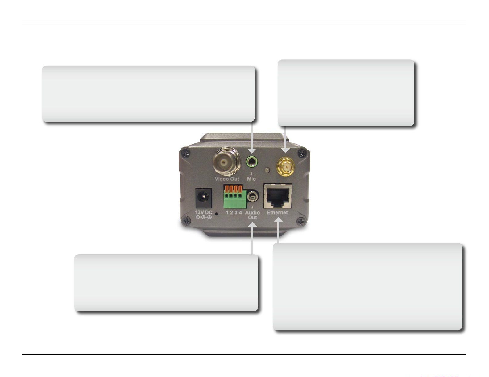
Hardware Overview
Microphone Connector
The DCS-3420 Wireless Day & Night Internet Camera
has an internal microphone built-in. However, you have
the option of using an external microphone by plugging
it into the microphone connector.
Antenna Connector
The antenna is included with the
DCS-3420. It fastens onto the
antenna connector on the back
panel to provide a connection with
a wireless network.
Audio Out Connector
The DCS-3420 provides an Audio Out connector
to be used for 2-way audio. Speakers (not
included) may be connected to the camera to
provide audio for 2-way communication.
Ethernet Cable Connector
The Internet Camera’s back panel features an
RJ-45 connector for connections to 10Base-T
Ethernet cabling or 100Base-TX Fast Ethernet
cabling. This network port supports the NWay
protocol, allowing the Internet Camera to
automatically detect or negotiate the transmission
speed of the network.
7D-Link DCS-3420 User Manual
Page 8

Section 1 - Product Overview
Hardware Overview
BNC
The BNC connector is used for professional
video connections. It benets users who
integrate digital IP camera into traditional
system (CCTV) for both analog and digital
video streaming purpose.
Power LED
The power LED is positioned on the back of the camera
lens next to the antenna connector. As soon as the power
adapter is connected to the camera, the power LED will ash
red and green several times, indicating that the DCS-3420 is
conducting a self-test. Upon passing the self-test, the LED will
turn green, indicating a good connection to an Ethernet port.
A red LED indicates that no connection has been made.
DC Power Connector
The DC power input connector is located on
the DCS-3420 Internet Camera’s back panel
and is labeled 12V DC with a single socket
to supply power to the Internet Camera.
Reset Button
Reset will be initiated when the reset button
is pressed once and held until the Power LED
ashes through its cycle twice.
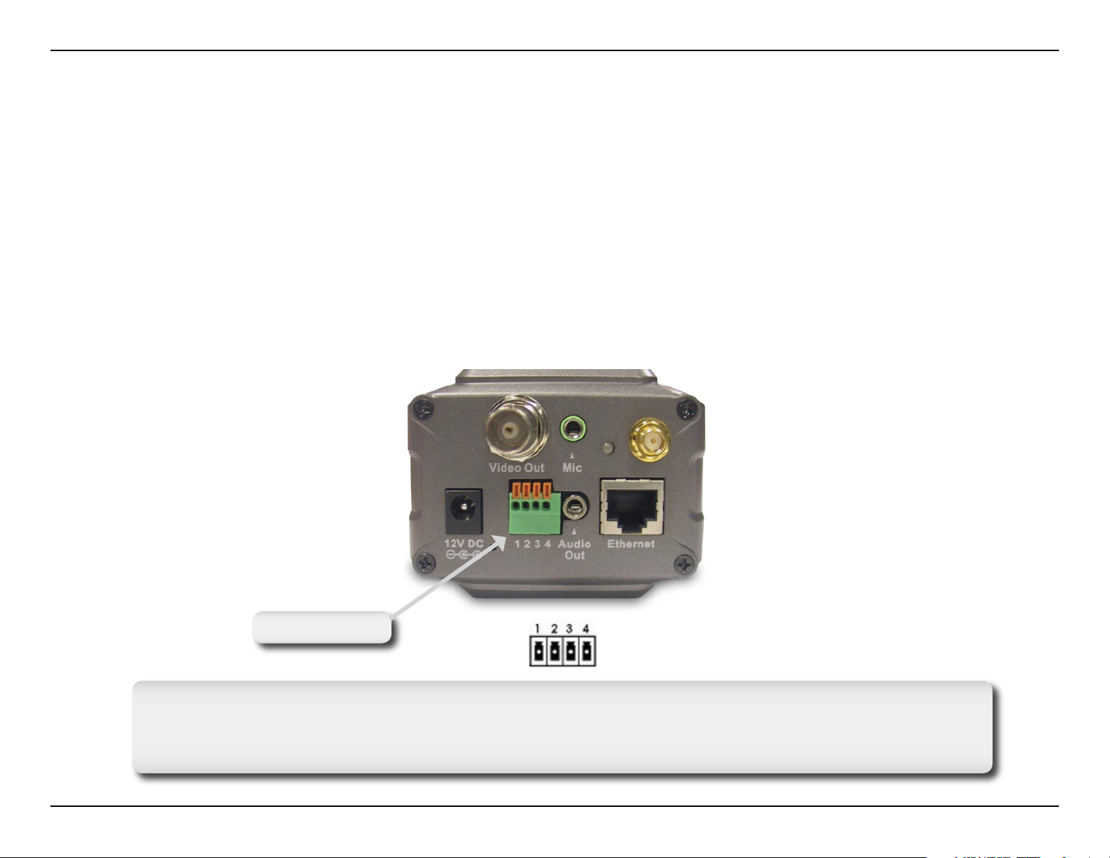
I/O Connector
The DCS-3420 provides a terminal block with two pairs
of connectors situated on the back panel. One pair is
for input and the other is for output. The I/O connectors
provide the physical interface to send and receive digital
signals to and from a variety of external devices.
8D-Link DCS-3420 User Manual
Page 9

Section 1 - Product Overview
Hardware Installation
If your are connecting the DCS-3420 to a wired Ethernet network, connect an
Ethernet cable to the network cable connector located to the network cable connector
located on the camera’s back panel and attach it to the network.
Note: It is required that an Ethernet cable is used during initial setup. Once your
wireless configuration is set, you may disconnect the Ethernet cable and begin
communicating wirelessly with your DCS-3420.
Locate the antennas included with your DCS-3420 and attach them to the antenna
connectors located on the back of the DCS-3420.
Attach the external power supply to the DC power input connector located on the
Internet Camera’s back panel (labeled 12VDC) and connect it to your wall outlet.
Note: When you have a proper connection, the LED will turn from red to green.
The light may cycle on and off and your computer may show an intermittent loss of
connectivity, this is normal until you have configured your Internet Camera.
9D-Link DCS-3420 User Manual
Page 10
Section 1 - Product Overview
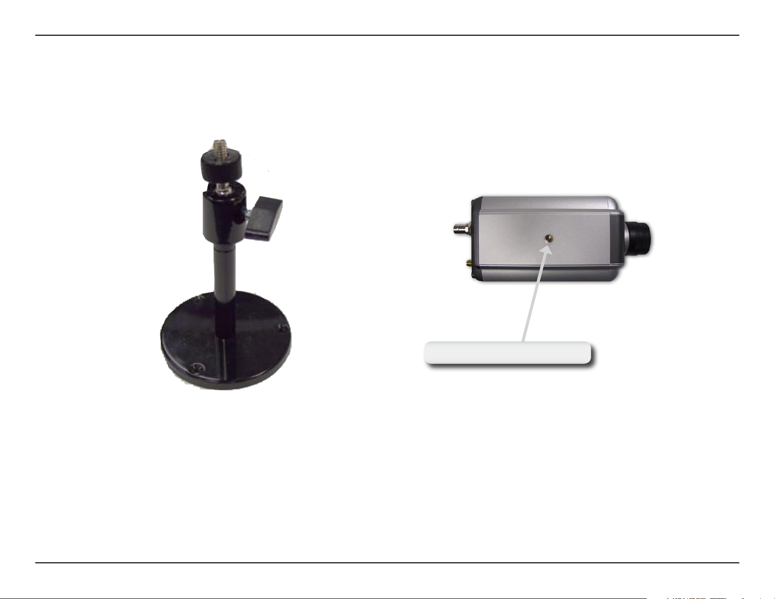
The Internet Camera comes with a camera stand with a swivel ball screw head that can be attached to the Internet
Camera bottom socket cavity. Attach the camera stand to the Internet Camera and station it for your application. There
are holes located in the base of the camera stand allowing the Internet Camera to be mounted to the ceiling, or any
wall securely.
Socket for camera stand
10D-Link DCS-3420 User Manual
Page 11

Section 2 - Installation
Installation
Wireless Installation Considerations
The D-Link wireless internet camera lets you access your network using a wireless connection from virtually anywhere
within the operating range of your wireless network. Keep in mind, however, that the number, thickness and location of
walls, ceilings, or other objects that the wireless signals must pass through, may limit the range. Typical ranges vary
depending on the types of materials and background RF (radio frequency) noise in your home or business. The key
to maximizing wireless range is to follow these basic guidelines:
1. Keep the number of walls and ceilings between the D-Link adapter and other network devices to a
minimum - each wall or ceiling can reduce your adapter’s range from 3-90 feet (1-30 meters.) Position
your devices so that the number of walls or ceilings is minimized.
2. Be aware of the direct line between network devices. A wall that is 1.5 feet thick (.5 meters), at a
45-degree angle appears to be almost 3 feet (1 meter) thick. At a 2-degree angle it looks over 42 feet
(14 meters) thick! Position devices so that the signal will travel straight through a wall or ceiling (instead
of at an angle) for better reception.
3. Building Materials make a difference. A solid metal door or aluminum studs may have a negative effect on
range. Try to position access points, wireless routers, and computers so that the signal passes through
drywall or open doorways. Materials and objects such as glass, steel, metal, walls with insulation, water
(sh tanks), mirrors, le cabinets, brick, and concrete will degrade your wireless signal.
4. Keep your product away (at least 3-6 feet or 1-2 meters) from electrical devices or appliances that
generate RF noise.
5. If you are using 2.4GHz cordless phones or X-10 (wireless products such as ceiling fans, lights, and
home security systems), your wireless connection may degrade dramatically or drop completely. Make
sure your 2.4GHz phone base is as far away from your wireless devices as possible. The base transmits
a signal even if the phone in not in use.
11D-Link DCS-3420 User Manual
Page 12

Section 2 - Installation
Software Installation
Turn on the computer and Insert the D-Link DCS-3420 Driver CD in the CD-ROM drive. The step-by-step instructions that
follow are shown in Windows® XP. The steps and screens are similar for the other Windows® operating systems.
Click Installation Wizard
If the CD Autorun function does not automatically start on your computer, click Windows® Start > Run. In the Run
command box type “D:\DCS3420.exe”, where D: represents the drive letter of your CD-ROM. If it does start, proceed
to the next screen.
12D-Link DCS-3420 User Manual
Page 13

Section 2 - Installation
Please wait while the InstallShield Wizard prepares to install.
Click Next
13D-Link DCS-3420 User Manual
Page 14

Section 2 - Installation
The InstallShield will install the driver in the following folder. To
install the driver into a different folder, click Browse and select
another folder.
Click Next
Select the Program folder that Setup will add program icons to.
You may type a new folder name, or select one from the existing
folders list.
Click Next
14D-Link DCS-3420 User Manual
Page 15
Section 2 - Installation
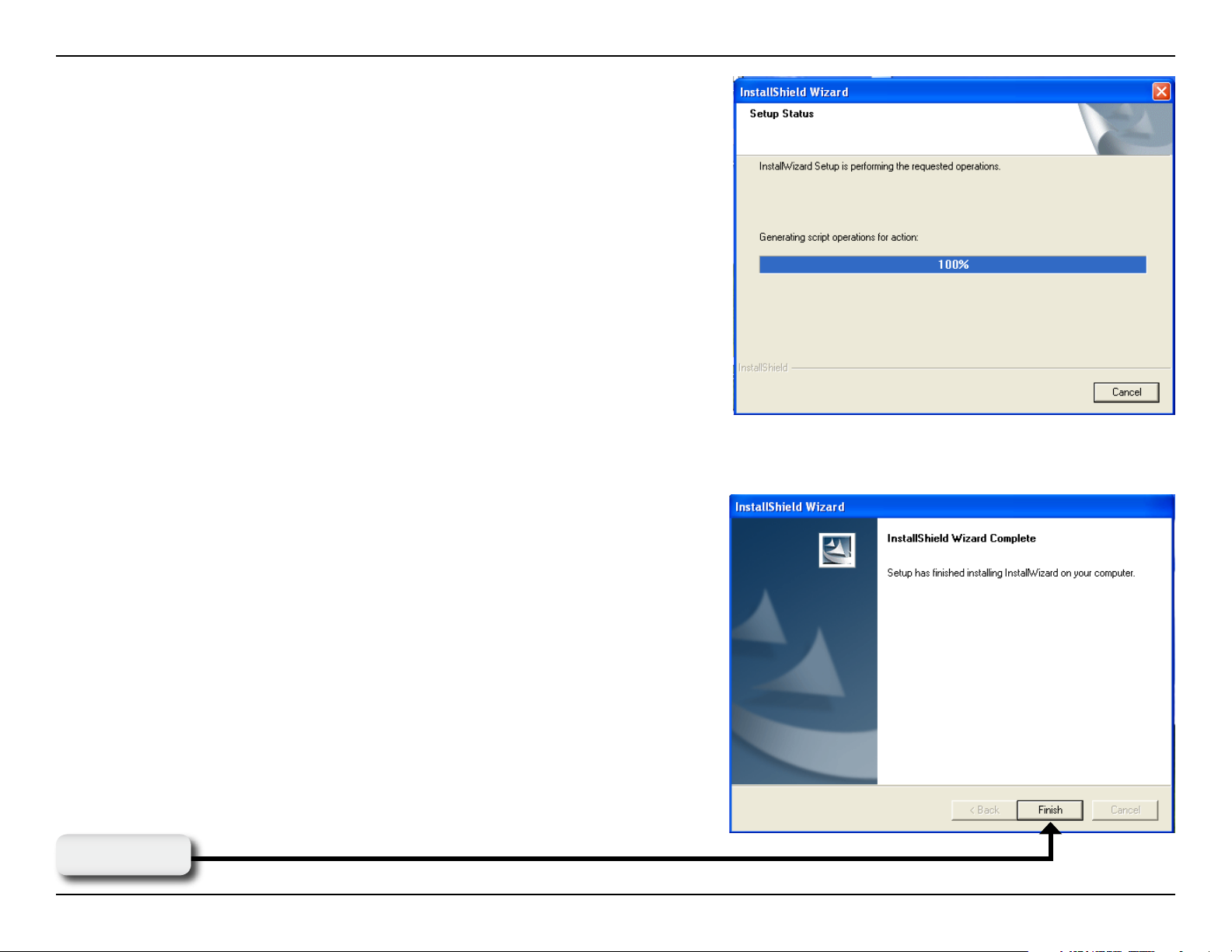
Please wait while the Installation Wizard is installed.
Installation is now complete.
Click Finish
15D-Link DCS-3420 User Manual
Page 16

Section 2 - Installation
To access the Installation Wizard screen, click on the Installation Wizard Icon on your desktop.
The opening Installation Wizard screen will appear and show a MAC address of the DCS-3420 and an IP Address. If
you have a DHCP* server on your network, there will be a valid IP Address displayed here, indicated by a “Yes” under
the assigned column.
*A DHCP server is a device that supplies IP Addresses to its clients that are on the same network.
16D-Link DCS-3420 User Manual
Page 17

Section 3 - Configuration
Configuration
This section will show you how to congure your new D-Link wireless internet camera using the D-Link Installation
Wizard.
Installation Wizard
The following options are available on the Installation Wizard screen by clicking on the corresponding tab:
Click Setup
17D-Link DCS-3420 User Manual
Page 18

Section 3 - Configuration
Setup
On the initial Setup Screen you can congure System and Date/Time settings for each camera. Click Next to
congure Network settings for the camera.
Click Next
18D-Link DCS-3420 User Manual
Page 19
Section 3 - Configuration
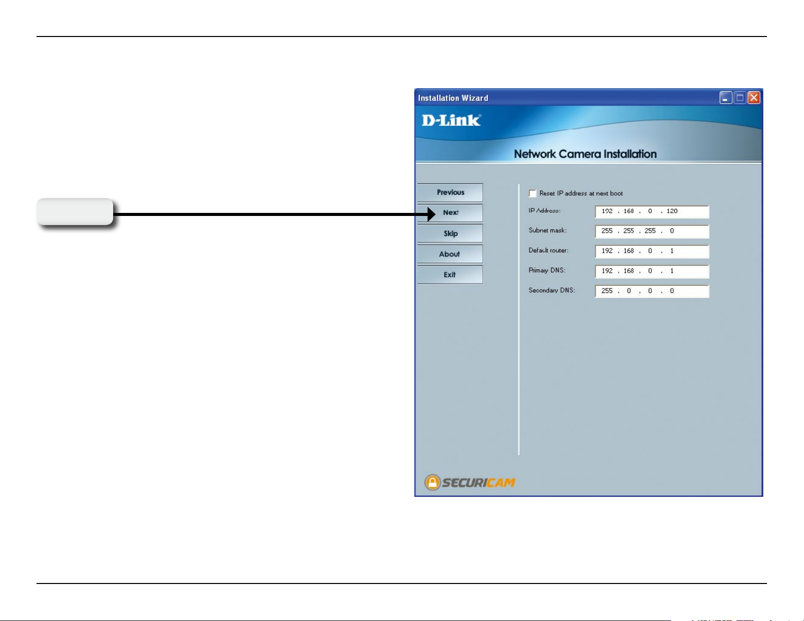
Network Settings
Users can congure the Network Settings for the camera
by entering the IP address, Subnet mask, Default router IP,
Primary DNS, and Secondary DNS. The option to reset IP
address at next boot is automatically selected. If you would
like to keep your IP address settings, make sure to uncheck
this box.
Click Next
19D-Link DCS-3420 User Manual
Page 20

Section 3 - Configuration
Wireless Network Settings
Users can congure the Wireless Network Settings for
the camera, by entering the SSID and selecting the
Wireless Mode, Channel, TX Rate, and Preamble.
Click Next
Note: Check the Data Encryption box to enable data
encryption and congure the settings. These settings are
explained and can also be configured on the Advanced >
Network screen (page 33) when configuring the camera
via a Web Browser.
20D-Link DCS-3420 User Manual
Page 21

Section 3 - Configuration
Click Apply to save the congured settings. Users can click
Previous to modify changes.
Click Apply
21D-Link DCS-3420 User Manual
Page 22
Section 3 - Configuration
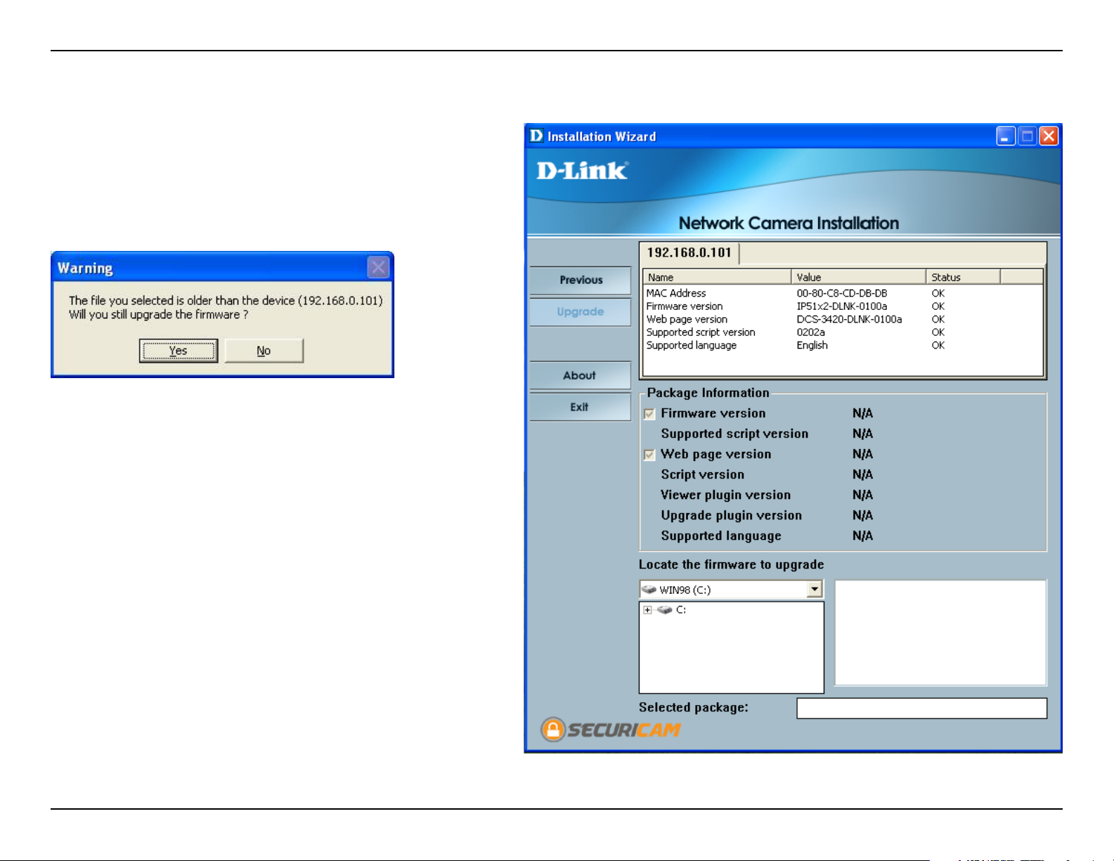
Upgrade
The upgrade window allows users to upload the
rmware. If the rmware is older than the current one
on the camera, a screen shot will appear indicating this,
prompting the user to conrm the uploading.
22D-Link DCS-3420 User Manual
Page 23

Section 3 - Configuration
Enabling UPnP for Windows® XP
UPnP (Universal Plug and Play) is a networking architecture that provides
compatibility among networking equipment, software, and peripherals. The
DCS-3420 is an UPnP enabled Internet camera. If your operating system is
UPnP enabled, the device will be easier to congure. If you do not want to use
the UPnP functionality, it can be disabled by unchecking the Enabled UPnP
checkbox in the Advanced > Network page (see page 33). Use the following
steps to enable UPnP settings only if you are running Windows® XP. If you are
running Windows® 98/2000, UPnP is not available.
Go to Start >Settings. Click Control Panel.
Click Add or Remove Programs
23D-Link DCS-3420 User Manual
Page 24

Section 3 - Configuration
Click Add/Remove Windows Components
The following screen will appear.
Select Networking Services.
Click Details
Select Universal Plug and Play.
Click OK
24D-Link DCS-3420 User Manual
Page 25

Section 3 - Configuration
Click Next
Please wait while Setup congures the components.
Click Finish
25D-Link DCS-3420 User Manual
Page 26
Section 3 - Configuration
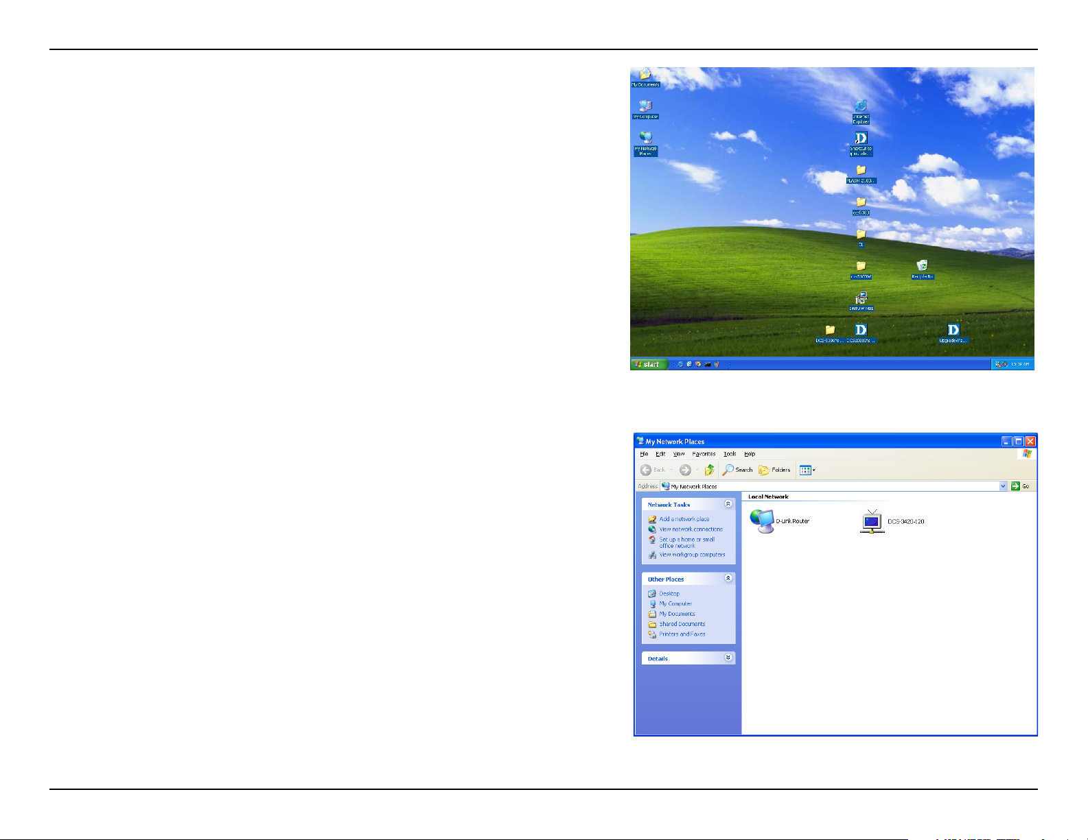
To view your DCS-3420 Internet Camera in an Internet browser, go
to your Desktop and click My Network Places.
The last three digits (120), represent the fourth octet of your Internet
Camera’s IP address (in this example, 198.168.0.120). Click
DCS-3420-120.
26D-Link DCS-3420 User Manual
Page 27
Section 3 - Configuration
After you click on the DCS-3420-120 icon, your Internet browser will automatically be opened to the IP Address
of the DCS-3420, in this example it is: http://192.168.0.120. Your DCS-3420 may have a different IP Address.
(Note: Screen shots are taken in Windows® XP, similar screens will appear in Windows® 2000.)
27D-Link DCS-3420 User Manual
Page 28
Section 3 - Configuration
Testing the DCS-3420
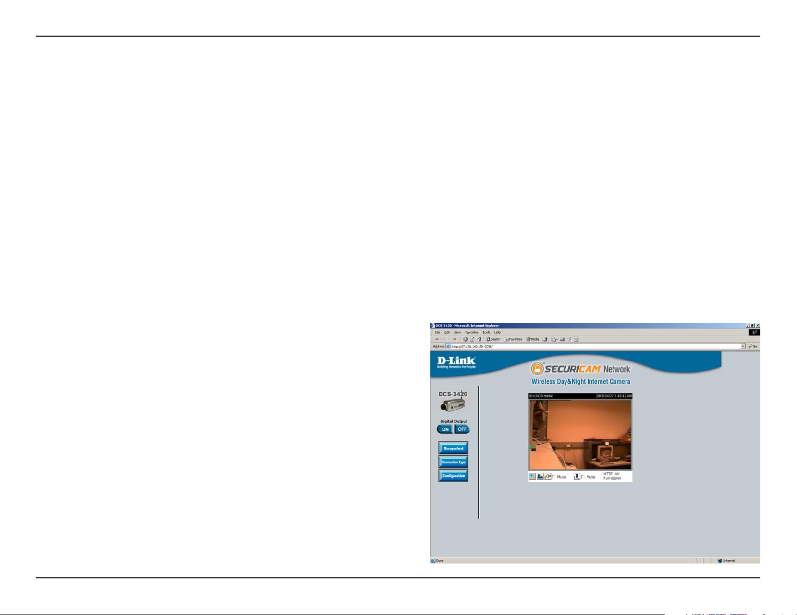
Open your Internet browser and type in the IP address of the DCS-3420. In this example, the address is: http://192.168.0.120
(your DCS-3420 may have a different IP address based on what you used in the Installation Wizard program).
The window in the center of your browser is the camera image window. You should now see a video image and hear the
audio over your computer speakers from the DCS-3420. If you are having problems, please consult the Troubleshooting
section of this manual (page 131).
28D-Link DCS-3420 User Manual
Page 29
Section 3 - Configuration
Viewing Your DCS-3420
After all the router settings have been entered correctly, a PC user inside or outside your network will have access to
the camera through the Internet Explorer Web browser. To access the camera from the Internet, type the IP Address
of the router given to you by your ISP, followed by a colon, and the port number that you gave your camera (e.g.,
http://70.42.15.9:83). It is not necessary to enter the colon and port number if you are using the default Web server
port 80. To access from a computer on your local (home) network, simply enter the local IP Address of the Camera
followed by a colon and the port number (e.g., http://192.168.0.120:83).
If you are following this manual in the order it is presented, you should now have an operating DCS-3420 Internet
Camera congured with the Installer program. You also have installed the IP surveillance software from the CD. This
section of the manual will cover how to use the Internet Camera in two methods:
• Using the DCS-3420 with an Internet browser and accessing the screens to control and monitor the camera.
• Using IP surveillance software with the DCS-3420.
29D-Link DCS-3420 User Manual
Page 30
Section 3 - Configuration
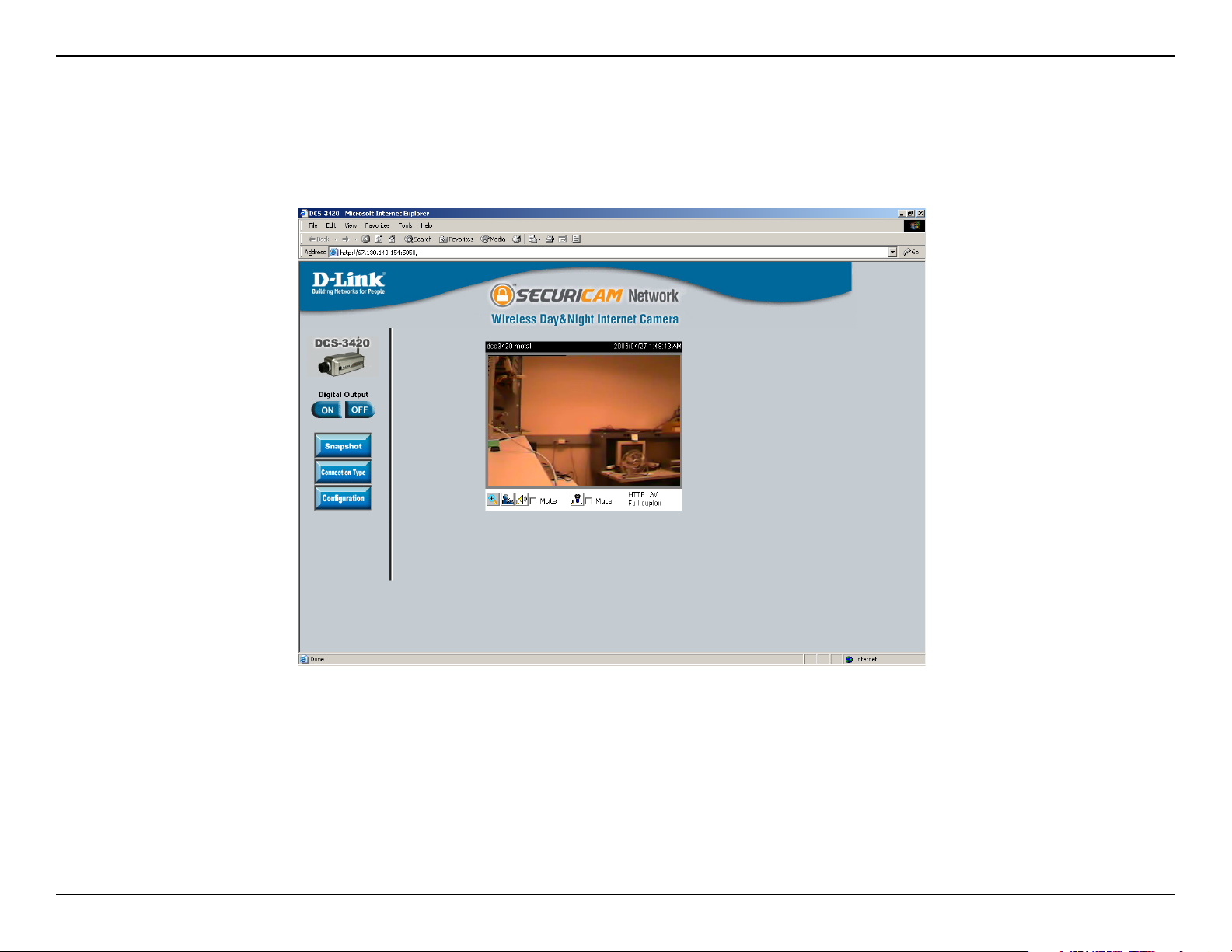
Using the DCS-3420 with an Internet Browser
Open your Internet Explorer Web browser and enter the IP address for your Internet Camera (http://192.168.0.120).
In the example, this address is 192.168.0.120. Your address may differ.
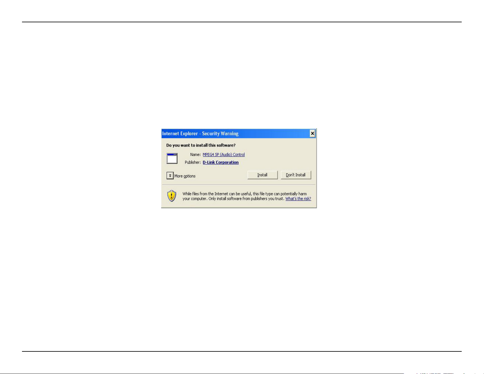
If a window appears asking to install a Verisign certicate for authentication Click Yes. This allows the proprietary
MPEG4 video stream to be recognized by Internet Explorer.
30D-Link DCS-3420 User Manual
Page 31

Section 3 - Configuration
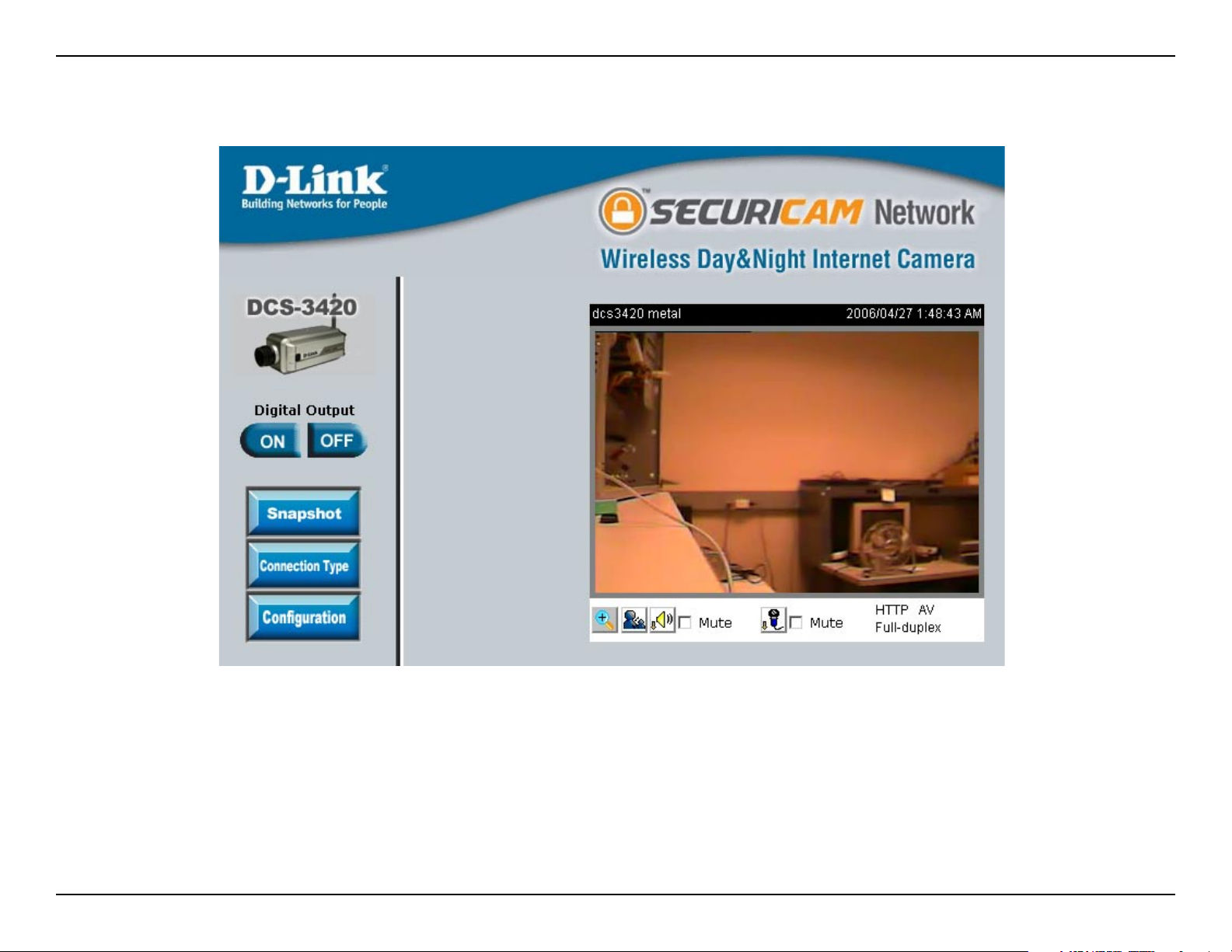
Home
Snapshot:
Connection Type:
Configuration:
Push/Toggle:
Click to capture a snapshot image. The
image will pop up in a new window.
This image can be saved to a local hard
drive.
Click on the Connection Type button to
change settings related to the camera
connection.
Click on the Configuration button to
access the conguration menu where
you can congure camera settings under
the Advanced, Tools, and Status tabs.
Push to enable the speaker. You can set
the speaker button operation to either
Push or Toggle on the Connection Type
screen.
Speaker Volume
Control:
Mute Speaker:
Microphone
Volume Control:
Mute
Microphone:
Click to increase or decrease speaker
volume.
Click to mute the speaker.
Click to increase or decrease microphone
volume.
C l i c k t o m u t e t h e c a m e r a ’ s
microphone.
31D-Link DCS-3420 User Manual
Page 32

Section 3 - Configuration
Connection Type
Disable Audio:
Speaker Button
Operation:
Protocol
Option:
Option for users to disable or enable
audio when viewing video.
If Push is selected, the user must push
and hold the speaker button each time to
speak. If Toggle is selected, pushing the
speaker button turns the speaker function
on and it remains on until the user toggles
the button off.
The UDP Protocol should be chosen
for the most users. Generally, the client
computer will automatically try these
protocols in the following order, UDP > TCP. After the client connects to the
DCS-3420 successfully, the working
protocol will be displayed in Protocol
Option. The chosen protocol will be saved in the user’s PC and used for the next connection. If
the network environment is changed or users want to let the Web browser automatically detect the
protocol, select UDP manually and click Save to change the setting and return Home to reconnect
with the new setting.
Options:
UDP Protocol - Allows for more real-time audio and video streams. However, packets may be dropped
and images obscured due to network burst trafc.
HTTP Protocol - This protocol must be selected if the network is protected by a rewall that only allows
the HTTP Port (80) to be opened. If the user’s network does not require the use of a rewall, the UDP
protocol is recommended.
Click the Home tab to return to the DCS-3420 Home page.
32D-Link DCS-3420 User Manual
Page 33

Section 3 - Configuration
Advanced
Network
IP Address:
Subnet Mask:
Default Router:
Primary DNS:
Secondary DNS:
PPPoE:
Necessary for network identication.
Used to determine if the destination is
the same subnet. The default value is
“255.255.255.0.”
The router used to forward frames to
destinations in a different subnet. Invalid
router settings may cause the failure of
transmissions to a different subnet.
Primary domain name server that
translates names to IP addresses.
Secondary domain name server to
backup the primary one.
(Point-to-Point Protocol over Ethernet)
Select this option if the camera is directly
connected to the Internet through a DSL
modem, and the ISP (Internet Service
Provider) requires you to use PPPoE for the Internet connection. Input the authentication information from
your ISP into these elds. Note: The Internet (WAN) IP Address of the PPPoE will be sent through the
email.
33D-Link DCS-3420 User Manual
Page 34

Section 3 - Configuration
HTTP Port:
UDP audio port:
UDP video port:
Can be set to other than the default port 80. When the administrator changes the HTTP port of the
DCS-3420 (which has an IP address of 192.168.0.120) from 80 to 8080, users must type http://192.1
68.0.120:8080 in the web browser bar to bring up the web interface.
Can be set to a port other than the default port 5002. A corresponding port must be opened on your
rewall.
Can be set to a port other than the default port 5003. A corresponding port must be opened on your
rewall.
34D-Link DCS-3420 User Manual
Page 35

Section 3 - Configuration
Wireless
SSID:
Wireless Mode:
Channel:
(Service Set Identier) is a name that
identies a wireless network. Access
Points and wireless clientsattempting to
connect to a specic WLAN (Wireless
Local Area Network) must use the same
SSID. Thedefault setting is default.
Click on the pull-down menu; select from
the following options: Infrastructure - to
connect the WLAN using an Access
Point such as the DWL-1000AP+ or a
DI-614+ wireless router. (The default
setting.) Ad-Hoc – wireless mode used
when connecting directly to a computer
equipped with a wireless adapter in a
peer-to-peer environment.
The default wireless channel setting is
channel 6. Select the channel that is the
same as the otherwireless devices on
your network.
TX Rate:
Preamble:
Select the transmission rate on the network. Auto is the default setting.
Select Long or Short Preamble. The Preamble denes the length of the CRC block (CyclicRedundancy
Check is a common technique for detecting data transmission errors) for communication between the
Access Point and the roaming wireless Network adapters. Short Preamble is the defaultsetting. Note: High
network trafc areas should use the shorter preamble type.
35D-Link DCS-3420 User Manual
Page 36

Section 3 - Configuration
Security:
Pre-shared Key:
Auth mode:
Key Lenght:
Key Format:
Default Key:
Select the encryption type from the drop-down list. The default setting for the encryption is None, which
means the security is disabled.
This Key allows the camera to connect to other devices by using WPA-PSK encryption. Pre-shared key
must be 8-63 characters or 64 hex characters.
Choose one of the following authorization modes:Open Autenication- Communicates the key across
the network. Shared Authentication- Allows communication only with other devices with identical WEP
settings.
Select the key length, either 64 or 128 bits.
Select an ASCII or hexadecimal key format.
You can create up to 4 different security keys.
36D-Link DCS-3420 User Manual
Page 37
Section 3 - Configuration
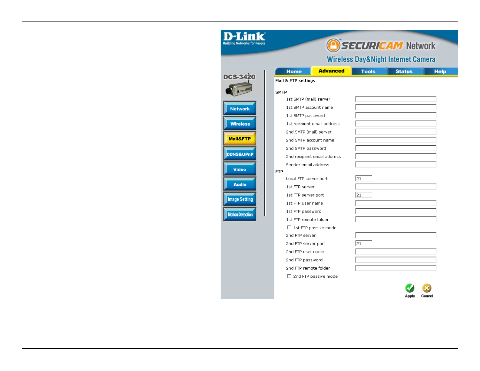
Mail & FTP
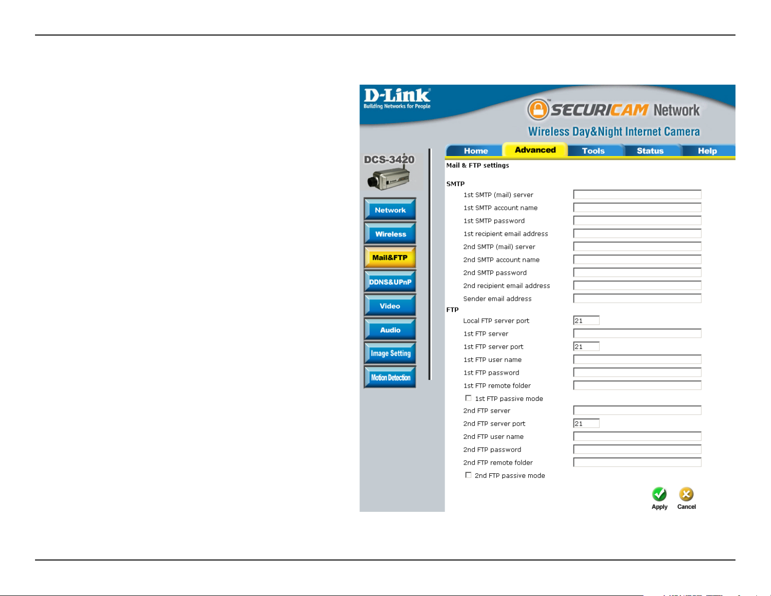
SMTP (mail)
server 1:
SMTP account
name 1:
SMTP
password 1:
Recipient email
address 1:
SMTP (mail)
sever 2:
The domain name or IP address of the
external mail server.
The user name used to log into your e-mail
account (e.g. jdoe or jdoe@yourisp.com
depending on your ISP).
The password used to log into your e-mail
account. (The password will appear as
dots instead of entered characters.)
The e-mail address of recipients for
snapshots or a system log le.
The domain name or IP address of a
secondary mail server used only if the
primary mail server is unreachable.
SMTP account
name 2:
SMTP
password 2:
Recipient email
address:
The user name for the second SMTP
server.
The password used to log into the
second e-mail account. (The password
will appear as dots instead of entered
characters.)
The e-mail address of recipients for the
secondary server.
37D-Link DCS-3420 User Manual
Page 38

Section 3 - Configuration
Sender Email
Address:
Local FTP
server port:
1st FTP
server:
1st FTP
server port:
1st FTP user
name:
1st FTP
password:
1st FTP remote
folder:
1st FTP Passive
Mode:
The sender’s email address that appears in the mail alert.
It can be other than default port 21. If you nd that you want to change the port to a port number other than
21, you will need to specify the port when connecting to the FTP server. For example FTP://68.5.1.81:60
(if you are to use port 60 for your FTP server port)
The host name of the FTP server.
The port of the FTP server. Usually the port number of FTP server is 21. It depends on the FTP server’s
setup.
The account name to access the FTP server.
The password that was setup with the account to access the FTP server.
The directory that the images will be uploaded into (For example, \pub\images).
Allows access to an external FTP sever if your camera is behind a router protected by a rewall.
2nd FTP
server:
2nd FTP user
name:
The 2nd FTP server serves as a backup FTP server.
The account name to access the FTP server.
38D-Link DCS-3420 User Manual
Page 39

Section 3 - Configuration
2nd FTP
password:
2nd FTP remote
folder:
2nd FTP passive
mode:
DDNS:
The password that was setup with the account to access the FTP server.
The directory that the images will be uploaded into (For example, \pub\images).
Passive mode setting for the backup FTP server.
DDNS & UPnP
Dynamic DNS (Domain Name Service)
is a method of keeping a domain
name linked to a changing (dynamic)
IP address. With most Cable and
DSL connections, you are assigned a
dynamic IP address and that address is
used only for the duration of that specic
connection. With the DCS-3420, you
can set up your DDNS service and the
DCS-3420 will automatically update your
DDNS server every time it receives a
different IP address.
Enable DDNS:
Provider:
Host Name:
Username/E-mail:
Check to enable the DDNS function.
Select your Dynamic DNS provider
from the drop down menu.
Enter the host name of the DDNS
server.
Enter your username or e-mail used to connect to the DDNS server.
39D-Link DCS-3420 User Manual
Page 40

Section 3 - Configuration
Password/Key:
UPnP:
Color:
Size:
Enter your password or key used to connect to the DDNS server.
UPnP is short for Universal Plug and Play, which is a networking architecture that provides compatibility
among networking equipment, software, and peripherals. The DCS-3420 is a UPnP enabled Internet camera.
If your operating system is UPnP enabled, the device will be easier to congure. If you do not want to use
the UPnP functionality, it can be disabled by unselecting the Enable UPnP check box.
Video
Select the option for color or monochrome
video display.
Three options exist for the video display:
176 x 120, 352 x 240, and 704 x 480.
In 704x480 mode, the frame rate will be
reduced to 10fps and increased to 30fps
automatically when it is switched back
to a lower image size.
Maximum
frame rate:
Key Frame
Interval:
Limits the maximum refresh frame
rate. The frame rate is used with the
Video quality control setting (below)
to optimize bandwidth utilization and
video quality.
The keyframe interval value tells the
camera how often to re-evaluate the
video image and record a full frame, or
keyframe, into the video stream.
40D-Link DCS-3420 User Manual
Page 41

Section 3 - Configuration
Video quality
control:
Flip:
Mirror:
Improve efficiency
in the multi-user
environment:
Timestamp on
video:
To x the bandwidth utilization regardless of the video quality, choose Fix bit rate and select the desired
bandwidth. The video quality may be reduced in order to send maximum frames with limited bandwidth,
especially when images change drastically. For higher video detail regardless of the bandwidth selection,
select Fix quality and select a video quality level. This setting will utilize more bandwidth to send the
maximum frames when images change drastically.
Vertically rotate the video.
Horizontally rotate the video. Check both ip and mirror if the DCS-3420 is to be installed upside down.
If the camera works in a multi-user environment, the user can enable this option to conserve bandwidth by
reducing video capture rate.
Select this option to display the current date and time on the video image. All the snapshots and video data
will have the date and time locate on the corner of the picture.
41D-Link DCS-3420 User Manual
Page 42

Section 3 - Configuration
Recommendations for Setting Video for the Best Performance:
“Best performance” means the image refresh rate should be the fastest possible and the video quality should
be the best possible at the lowest network bandwidth possible. Three factors, Maximum frame rate, Fix bit rate,
and Fix quality in the Video Conguration page, are related to performance.
Recording settings for real-time motion images
To achieve a real-time visual effect, the network bandwidth should be large enough to transmit 20 image frames
per second (fps) or more. If you are on a broadband network over 1 Mbps, you can set Fix bit Rate to 1000Kbps
or 1200Kbps, or set Fix quality to achieve the maximum frames. The maximum frame rate is 25 in 50Hz system
and 30 in 60Hz system. If your network bandwidth is more than 384Kbps, you can adjust Fix bit rate according
to your bandwidth and set the maximum frame rate of 25 to 30.
If the images vary dramatically in your environment, you may slow down the maximum frame rate to 20 to decrease
the transmitted data for better video quality. Since the human eye could not easily differentiate between 20 and 25
or 30 frames per second, the slower frame rate will not be noticed. If your network bandwidth is below 384 Kbps,
you should adjust the bit rate according to your bandwidth and experiment to allow for the best frame rate that can
be achieved. The faster frame rate in a slow network will blur the images. You may also try to choose 320x240
in size option for better images or 640x480 for larger image size. Because the network has burst constraints and
everyone’s environment is not the same, any poor connection will impair normal performance.
Recording settings for clear identication for each image
To have the best video quality, you should set Fix quality to detailed or excellent and tune the Maximum frame
rate to suit your network bandwidth. If you get some broken pictures in a slow network, you can set TCP protocol
in Connection type for a more accurate transmission but the received images may have a lag. Note that any slow
connection with multiple users will impair performance.
Recording settings to compromise between real-time and clear images
If you have a broadband network, set Fix quality to Good image quality, or higher, instead of setting the Bit rate.
Otherwise, x the bit rate according to your actual network speed and set the frame rate to 30. If the image quality
is low, select a lower frame rate above 15. If the image quality is still not improved, select a lower bit rate.
42D-Link DCS-3420 User Manual
Page 43
Section 3 - Configuration
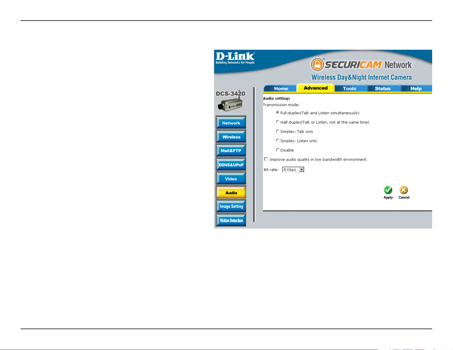
Audio
Transmission
mode:
Full-duplex:
Half-duplex:
Simplex/Talk only:
Simplex/Listen
only:
Disable:
Improve audio
quality in low
bandwidth
environment:
There are ve options to select. For all
the modes, only one client can talk to the
server at the same time.
The User can talk to and listen from the
server simnltaneously.
The User can talk to the server or listen
from the server, but not at the same
time.
The User can only talk to the server.
The User can only listen from the server.
The audio is disabled in both directions.
If the Network Camera works in a low
bandwidth network environment, the User
can check this option to improve audio quality by sacricing some real-time synchronization.
Bit rate:
There are three bit rates for audio. 32Kbps and 24Kbps are suitable for both music and speech and 8Kbps
is suitable for speech only.
43D-Link DCS-3420 User Manual
Page 44

Section 3 - Configuration
Image Setting
From this screen you can ne tune the video image.
Image Brightness, Contrast, Saturation and Hue are all adjustable in the same manner. For each video
compensation, you can set from among eleven levels ranged from -5 to +5. The default setting is zero for each
adjustment.
You may use the Preview and Restore button to ne-tune the image. Press the Save button to store the image
settings, or press the Restore button to recall the original settings. If settings are changed without saving, they will
be effective until the next system start-up.
44D-Link DCS-3420 User Manual
Page 45
Section 3 - Configuration
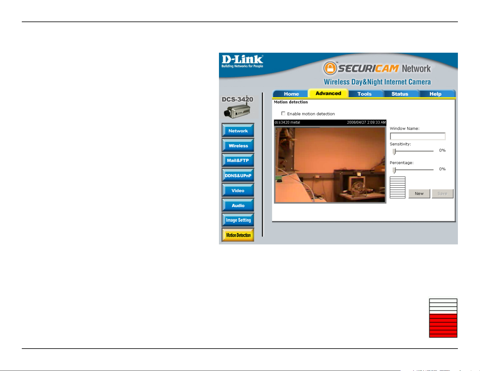
Motion Detection
Enable motion
detection:
Window name:
Sensitivity:
Percentage:
New:
Check this option to turn on the motion
detection.
The name of the motion detection
window.
Sensitivity meter allows the user to set
how sensitive for the motion triggering.
The sensitivity is based on pixel change
of the video image.
Percentage meter allows use to specify
how many percentage of the motion
screen is changed to trigger the motion
detection. Lower percentage gives higher
sensitivity of the motion detection.
Adds new windows that monitor specic
area of the image window. Up to 3 motion
detection windows can be added.
Save:
Saves the new windows settings.
A green bar means the image variation is under the monitoring level, and no motion detection alert is triggered. A red
bar means the image variation is over the monitoring level and a motion detected alert is triggered. When
the bar goes red, the window that the motion is detected in will also be outlined in red (note: remember that
you can have up to 3 windows selected for motion detection). You can return to the DCS-3420 Home Page
and the monitored window will not be visible, but the red frame will show on the home page when motion is
detected.
45D-Link DCS-3420 User Manual
Page 46

Section 3 - Configuration
Tools
Admin
The DCS-3420 is designed without any passwords by
default. This allows the ability to access the DCS-3420
(including the Conguration) by anyone as long as
the IP address is known. It is recommended that you
enter a password to restrict others from accessing your
camera.
Type a password in the Admin Password eld to enable
protection, and then conrm the password in Conrm
Password eld.
This password is used to identify the administrator.
You can add accounts with User name and User
Password for other users in the Add user section. 20
user accounts can be added in maximum.
Guest Account:
This option allows a user to connect to a camera with view-only privileges. User name is demo. No password
is required. This is useful for demonstrations and keeps guests separate from users with accounts.
46D-Link DCS-3420 User Manual
Page 47
Section 3 - Configuration
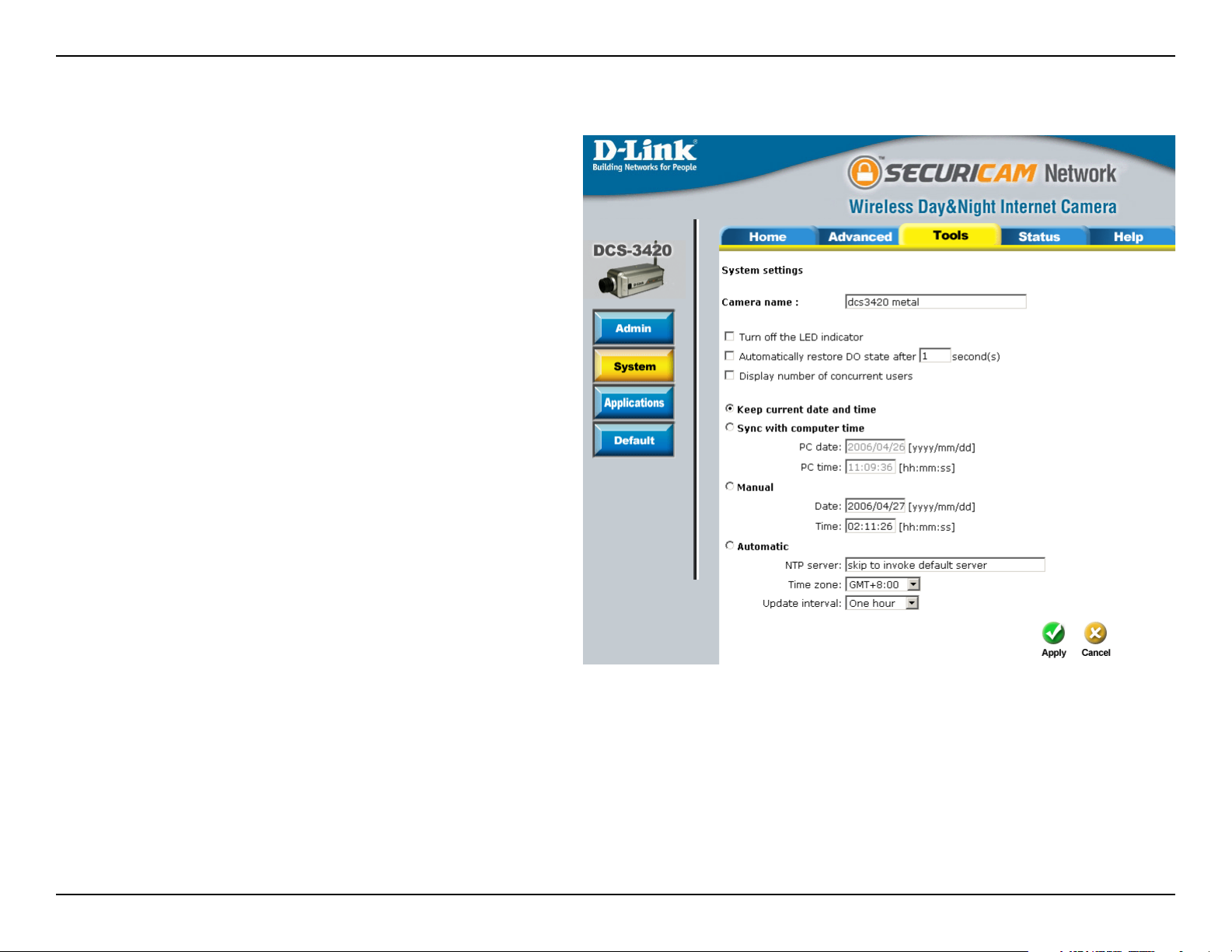
System
Camera name:
Turn off the
LED Indicator:
Keep current
date and time:
Sync with
computer time:
This name will be used to identify your
camera. Text entered will be displayed
in the black bar above the video window
with a timestamp set in the date and time
section.
Check this option to turn off the LED next
to the lens. This will prevent anyone from
observing the operation of the Internet
Camera.
Click to save the current date and time of
DCS-3420. An internal real-time clock
maintains the date and time even when
the power is off.
Synchronizes the date and time of your
camera with your computer.
Manual:
Automatic:
NTP Server:
Time Zone:
Adjust the date and time according to what
is entered by the administrator.
Synchronize with the NTP server over the Internet whenever the DCS-3420 starts up.
The IP address or domain name of the timeserver. Leaving the text box blank will let the DCS-3420 connect
to the default time servers.
Used to adjust the hour of time servers for local settings.
47D-Link DCS-3420 User Manual
Page 48

Section 3 - Configuration
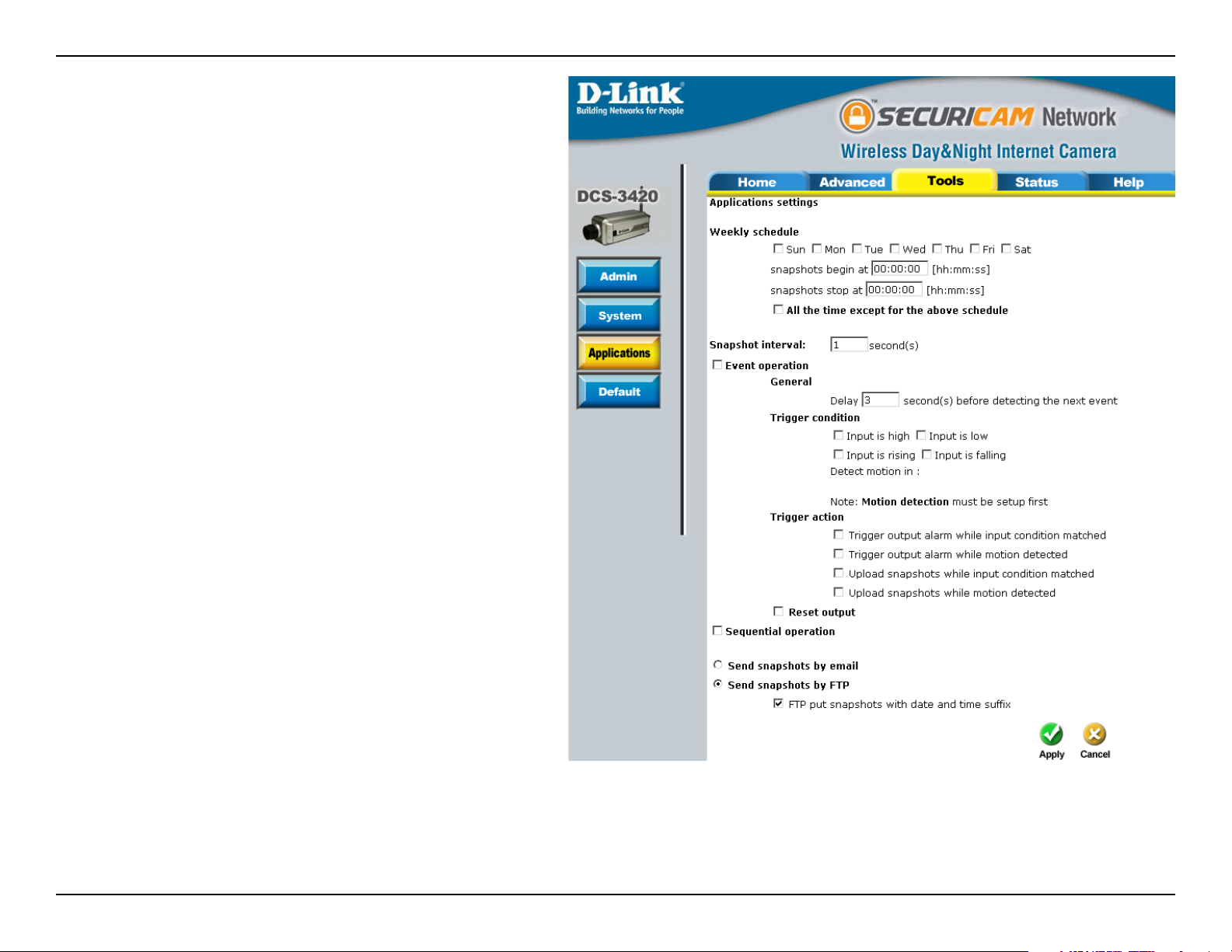
Applications
Sunday through
Saturday:
Snapshots
begin at:
Snapshot stop at:
All the time except
for the above
schedule:
Snapshot Interval:
Delay second(s)
before detecting
next event:
Select the day(s) according to when you want
your camera to take the snapshots.
Sets the time to start taking snapshots.
Sets the time to stop taking snapshots.
Sets the camera to take snapshots all the time
except for the times scheduled.
The camera will send snapshots at the specied
intervals to the external server.
Sets the time delay between triggered events.
48D-Link DCS-3420 User Manual
Page 49

Section 3 - Configuration
Trigger Condition:
Trigger Action:
Reset Output:
Sequential
operation:
Send snapshots
by email:
There are four conditions related to the digital input and up to three windows for motion detection. There
can be multiple selections. Select the appropriate digital input condition according to the characteristics
of the external device. High or low indicate external voltage input for level trigger, while rising or falling
is for edge triggers. There are three windows shown for the names you dened for motion detection.
Undened will show instead of the window title if motion detection is not setup yet. An active, named
motion window must be checked for motion detection operation.
Trigger action denes what action the camera will take after the trigger condition is matched. The camera
will be able to trigger output alarm (optimal requires Digital Outout setup. Please refer to page 57 for more
information.) or upload the snapshots.
Check and save this option to reset the external device at the digital output back to the original state.
The camera will send snapshots to the external server (FTP, Email) continuously, based on the snapshot
interval. These settings will correspond with the Weekly Schedule (Sun ~ Mon) that is specied in
Applications settings.
Any upload action specied in the options above will use the method chosen here. The captured snapshot
named “video.jpg” will be attached in the email with subject “Periodic snapshots.”
Send snapshots
by FTP:
FTP put
snapshots with
date and time
suffix:
The captured snapshots will upload to the external FTP server with the le name depending on the “FTP
put snapshots with date and time sufx” option.
If the sufx is added, the captured date and time can be easily differentiated from the snapshot le name
in either sequential or event operation. For instance, “video@20020102030405.jpg” means the JPEG
image was captured at 4 minutes and 5 seconds after 3 o’clock, January 2nd, A.D. 2002. If the sufx is
omitted, the le named “video.jpg” on the external FTP server will be refreshed at the specied interval.
49D-Link DCS-3420 User Manual
Page 50

Section 3 - Configuration
Default
Click Apply on this screen to restore the factory default settings. After conrmation, the system will restart and require
the Installation Wizard software program to locate the IP address of the DCS-3420.
For hard reset, please refer to page 7.
50D-Link DCS-3420 User Manual
Page 51

Section 3 - Configuration
Status
Device Info
51D-Link DCS-3420 User Manual
Page 52

Section 3 - Configuration
Log
The content of the log le reveals useful information about the current conguration and connection logged after the
DCS-3420 starts up.
52D-Link DCS-3420 User Manual
Page 53

Section 3 - Configuration
Help
The help page provides detailed information of the camera’s web interface.
53D-Link DCS-3420 User Manual
Page 54
Section 3 - Configuration
Record Snapshots to your FTP server
Administrators can combine options on the application page to perform many useful security applications. To upload
the snapshots, users can choose either email or FTP according to the user’s needs. Both e-mail and FTP use the
network settings on the network page. This section describes how to enable motion detecting and record snapshots
to an FTP server.
Administrators can utilize the built-in motion detection to monitor any abnormal movement and then record the snapshots
to a FTP server.
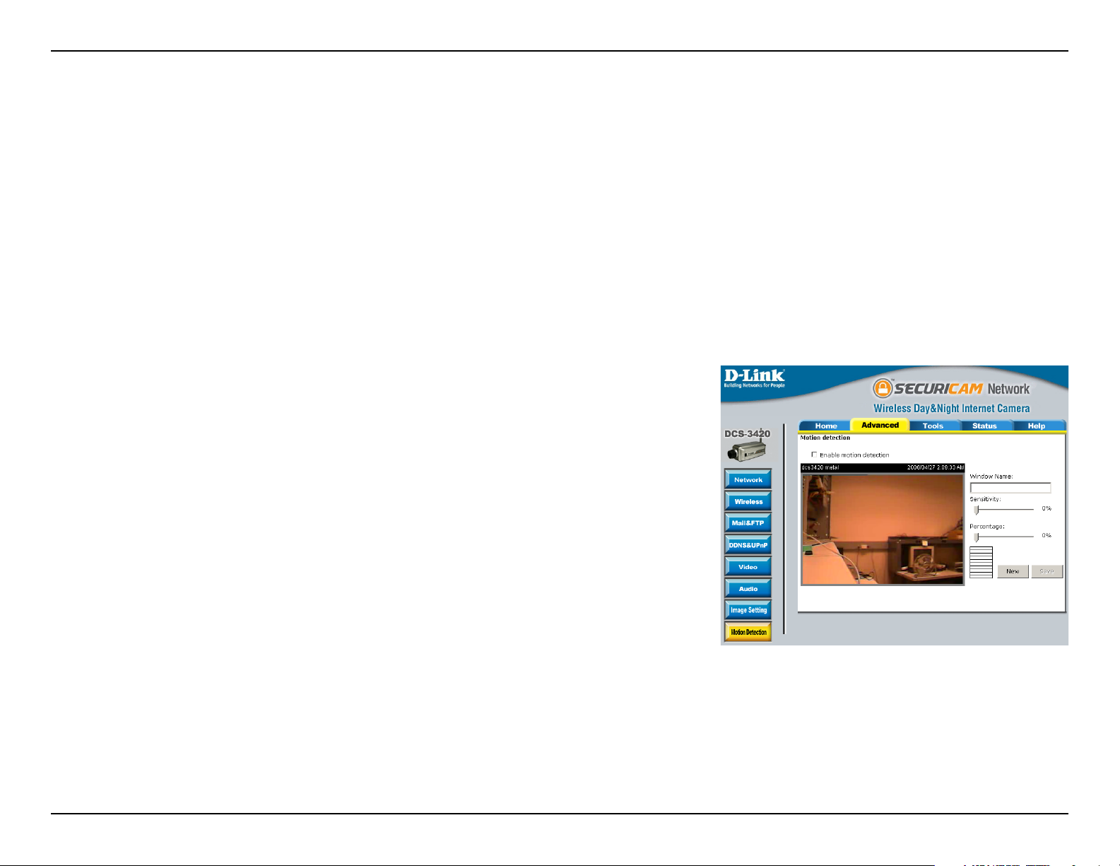
In this window, follow the steps below to ensure that motion detection is correctly enabled:
1 Check “Enable motion detection.”
2 Click on “New” to have a new window to monitor video.
3 Enter in a window name.
4 Tune the “Sensitivity” and “Percentage” according to the local
environment. Combined higher sensitivity with lower percentage
gives you high sensitivity for the motion detection.
5 Click on save to enable the activity display.
Next, click the Mail & FTP button under the Advanced tab to set the FTP server settings for the DCS-3420.
54D-Link DCS-3420 User Manual
Page 55
Section 3 - Configuration
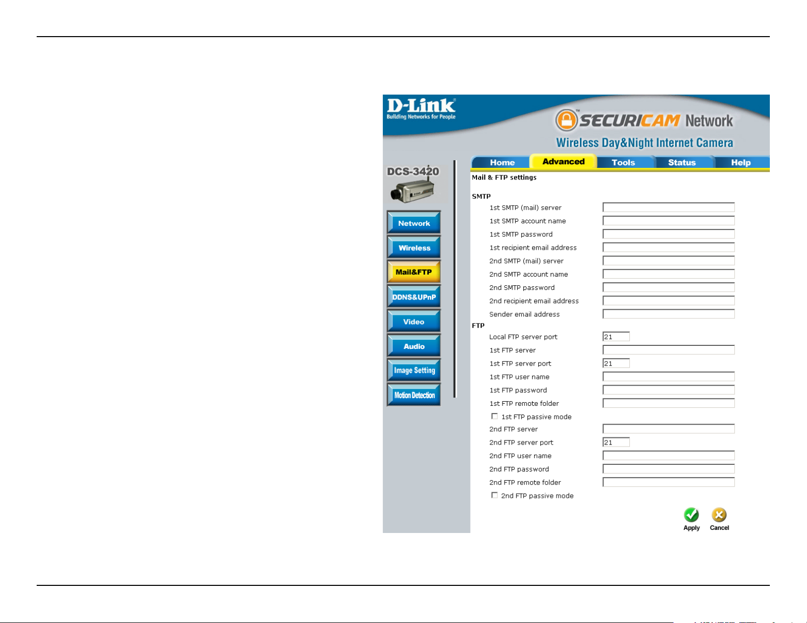
In this window, enter the settings for the FTP server you wish to upload the image to. Optionally, you can enter settings
for a secondary backup FTP server.
Local FTP
server port:
1st FTP server:
The Default port is 21. To connect to an
FTP server, it is recommended that you do
not change the port number unless your
camera is behind a router. If your camera
is behind a router, you can assign any port
number to this eld, but you must enable
port forwarding on the router. Please refer
to your router manual for more information
on port forwarding.
If you are going to upload snapshots to
an FTP server, you will need to ll in the
Domain name or IP address of your internal/
external FTP server such as ftp://dlink.com
or ftp://192.168.0.123. (The server name
and IP address will vary depending on the
user.) The following user settings must be
correctly congured for remote access.
1st FTP server
port:
1st FTP user
name:
1st FTP
password:
The port of the FTP server. The default is
21 for an external FTP site.
Specify the user name to access the
external FTP server (e.g. John Smith).
Specify the password to access the external
FTP server (e.g. 12345).
55D-Link DCS-3420 User Manual
Page 56

Section 3 - Configuration
1st FTP remote
folder:
Primary FTP
passive mode:
2nd FTP server:
2nd FTP sever port:
2nd FTP user name:
2nd FTP password:
2nd FTP remote
folder:
Secondary FTP
passive mode:
Specify the destination folder in the external FTP server (e.g. 123456).
Passive mode will allow access to an external FTP server if your camera is behind a router protected by
a rewall.
Specify the Domain name or IP address of your second external FTP server. This eld is optional if you
have already lled in the information for the rst FTP server.
The port of the FTP server. The default is 21 for an external FTP site.
Specify the user name to access your backup FTP server.
Specify the user password to your backup FTP server.
Specify the destination folder on your external backup FTP server.
Passive mode will allow access to a second external FTP server if your camera is behind a router protected
by a rewall.
56D-Link DCS-3420 User Manual
Page 57

Section 3 - Configuration
For detailed information about each setting, please
refer to Conguration > Advanced > Mail & FTP in the
section titled “Using the DCS-3420 With an Internet
Browser” (page 30). Click the apply button when
nished.
Next, click the Applications button under the Tools tab
to set the application settings for the DCS-3420.
In this window, follow the steps below to set the
application settings for snapshots to be recorded to
an FTP site:
1. Select the weekdays you would like to record
and enter the “Snapshots begin” time and
“Snapshots end” time for the weekly schedule, or
select “All the time except for the above schedule” if
you want to enable full time snapshot recording.
2. Check “Event operation.” Set the delay “before
detecting next event” to avoid continuous false
alarms following the original event. Set the
“Snapshot Interval” to capture the direction of the
moving object.
3. Check the window name.
4. Check “Upload snapshots while motion
detected.”
5. Click “Send snapshots by FTP” and check “FTP
put snapshots with date and time sufx.”
6. Click the “Apply” button to save the settings.
Click the apply button when nished. You are now able to record snapshots to your FTP server when motion
57D-Link DCS-3420 User Manual
Page 58
Section 3 - Configuration
I/O Connector
I/O Connector Denition for the Internet Camera
The DCS-3420 provides a general I/O terminal block with one digital input and one relay switch for device control. The
relay switch of pin 1 and pin 2 can be used to turn the external device on or off. Pin 3 and pin 4 can be connected to
an external sensor and the state of voltage will be monitored from the initial state ‘LOW’
The I/O connector provides the physical interface for digital output (DO) and digital input (DI) that is used for connecting
a diversity of external alarm devices to the Internet Camera such as IR-Sensors and alarm relays.
The digital input is used for connecting external alarm devices and once triggered images will be taken and e-mailed.
I / O
1 SW_COMMON OUTPUT (open from SW_OPEN at initial state)(close with SW_OPEN when set DO to ON)
2 SW_OPEN OUTPUT (Max. 1A, 24VDC or 0.5A, 125VAC)
3 DI+INPUT (Max. 50mA, 12VDC)
4 DI-INPUT (Initial state of DI is low)
58D-Link DCS-3420 User Manual
Page 59
Section 3 - Configuration
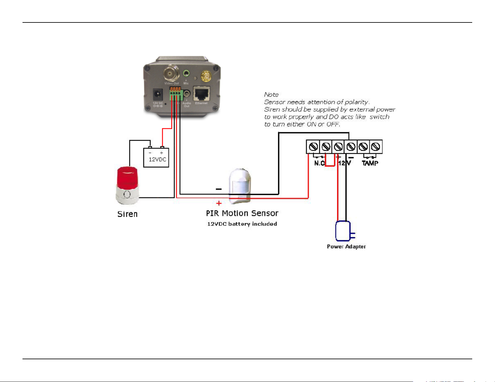
DI/DO Connection Diagram
The above diagram shows a typical wiring conguration for a normally closed PIR motion sensor. Please refer to your
specic motion sensor for the power supply connection to the device since this will be critical to the success of your
installation. Note that the positive from the PIR is connected to the D+ of the I/O port of the camera and the negative
from the PIR is connected to the D- of the camera I/O port.
Conguring Your Camera for External Trigger Based Recording
To congure your camera to record when triggered by an external device, you must rst set your SMTP or FTP settings in order to send snapshots to your email account or FTP server.
59D-Link DCS-3420 User Manual
Page 60
Section 3 - Configuration
Click the Network button under the Advanced
tab to set the SMTP or FTP server settings for the
DCS-3420.
In this window, enter the settings for the SMTP or
FTP server to which recorded snapshots will be sent.
For detailed information about each setting, please
refer to Conguration > Advanced > Mail & FTP
(page 37). Click the Apply button when nished.
60D-Link DCS-3420 User Manual
Page 61
Section 3 - Configuration
Next, click the Applications button under the
Tools tab to set the application settings for the
DCS-3420.
In this window, follow the steps below to set the
application settings for snapshots to be sent to your
email account or FTP server when triggered by a
motion sensor or other external device:
1. Select the weekdays you would like to record
and enter the “Snapshots begin” time and
“Snapshots end” time for the weekly schedule,
or select “All the time except for the above
schedule” if you want to enable full time
snapshot recording.
2. Check “Event operation.”
3. Set the delay “before detecting next event” to
avoid continuous false alarms following the
original event.
4. Set the “Snapshot Interval” to capture the
direction of the moving object.
5. Check the trigger condition for input and motion
detection (in this case “Input is Low”).
6. Check “Trigger output alarm while input
condition matched” and “Upload snapshots
while motion detected.”
7. Select to either send snapshots by email or by
FTP.
Click the Apply button when nished. You are now
able to send snapshots, based on triggered recording,
to your email account or FTP server.
61D-Link DCS-3420 User Manual
Page 62

Section 3 - Configuration
Adjusting the Camera Focus
The DCS-3420 Internet Camera features an interchangeable CS-type lens that can be used for different applications as
necessary. It supports rotational focus control so the lens can be adjusted to focus under normal and stable conditions
to maximize the image quality of the Internet Camera.
Fixed Lens Assembly
Do NOT adjust
To adjust the focus of the lens you will need to turn the lens
slowly either clockwise or counterclockwise until the desired
image appears. DO NOT overturn the lens in either direction
as it will be out of focus and may damage the camera. Unless
you want to substitute the lens DO NOT unscrew more than
1.0mm apart from the Fixed Lens Assembly.
Adjust the focus on the camera lens by
turning clockwise or counterclockwise
Note:
You can further adjust the Internet Camera’s image quality through the web conguration under:
Conguration > Advanced > Video
Please refer to the Conguration > Advanced > Video section (page 40) for further details.
62D-Link DCS-3420 User Manual
Page 63
Section 3 - Configuration
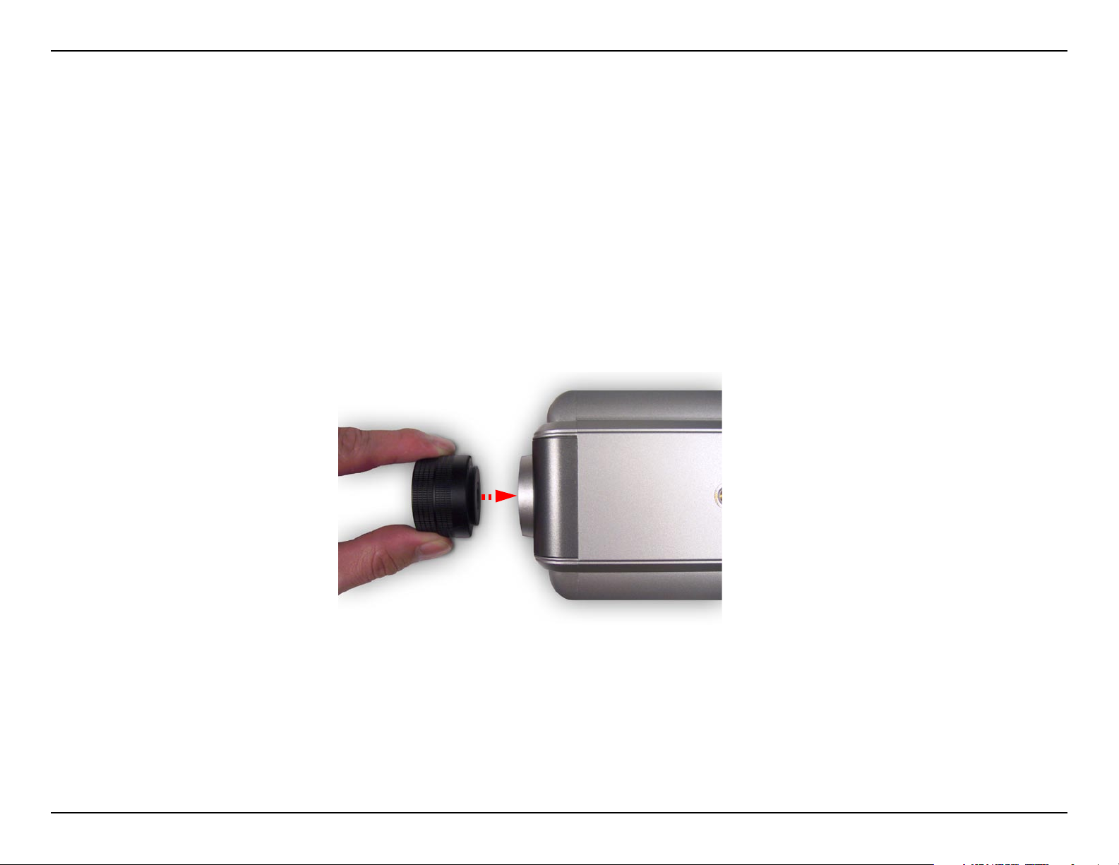
Replacing the Lens
Since the DCS-3420 Internet Camera is designed with a CS-mount, the lens equipped with the Internet Camera can
be replaced with any standard C or CS-mount lens commonly used within the surveillance industry.
Follow the instructions below to replace the supplied lens with any C or CS-mount lens.
1. Unscrew the Internet Camera lens
2. When using a C-mount lens, attach the new lens to a CS to C-mount adapter.
3. Screw the new lens onto the Internet Camera.
4. Refer to Adjusting the Internet Camera Focus on the previous page.
5. Refresh the Web browser and monitor the results from the Internet Camera.
WARNING: Direct exposure to sunlight may cause permanent damage to the CCD sensor. Therefore do not expose the
Internet Camera’s lens directly to sunlight. When operation is required in glaring light environment, it is recommended to
use an iris lens. The Internet Camera is designed for indoor usage and if your application requires prolonged exposure
to sunlight, a sun visor is recommended to protect the Internet Camera.
63D-Link DCS-3420 User Manual
Page 64
Section 3 - Configuration
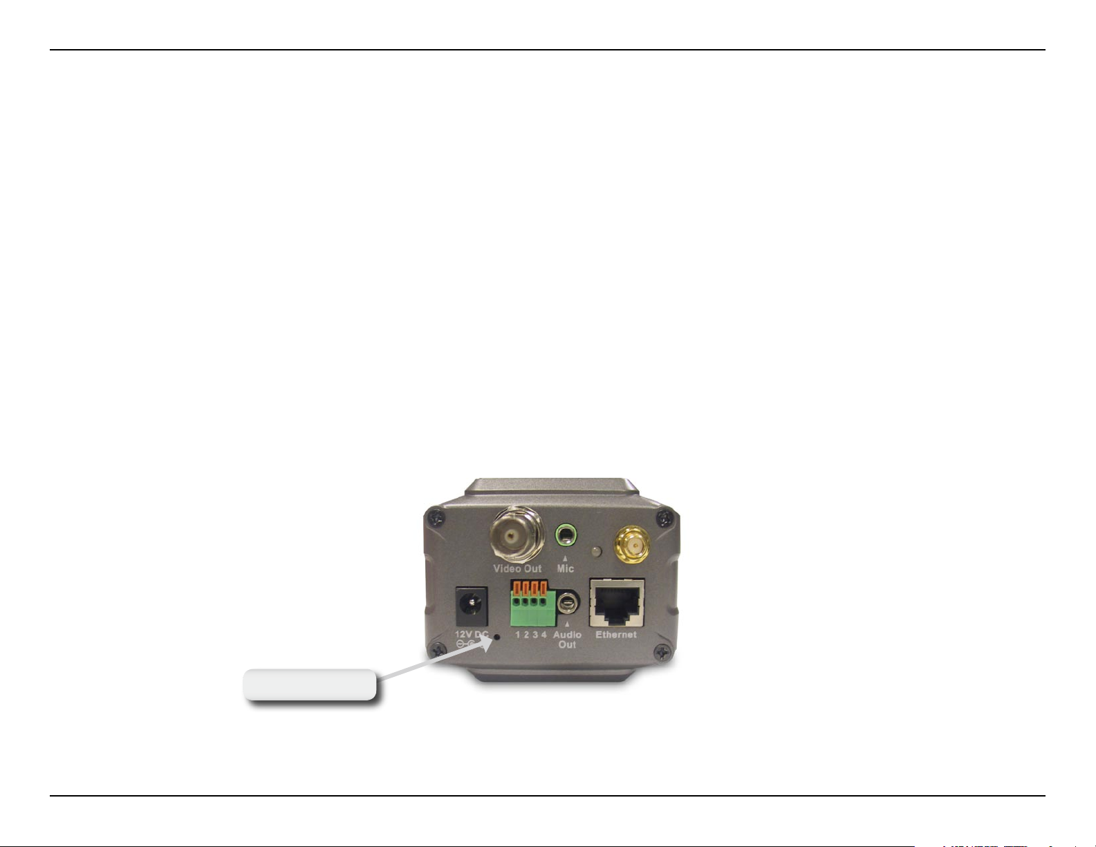
Reset and Restore
There is a button hidden in the pinhole beside the power socket. It is used to reset the system or restore the factory
default settings. Sometimes resetting the DCS-3420 will return the system back to a normal state. If the system still
has problems after reset, restore the factory settings and install again:
RESET: 1. Lightly insert a paper clip (or a similar sized tool) into the reset hole on the back of the camera, press
lightly and then release the button.
2. The LED on the back of the camera will begin blinking red and green fast.
3. When the LED stops the blinking fast and starts blinking once every second, the reset is completed.
RESTORE: 1. Insert the paper clip, or another similar tool, and press and continuously hold down the button
recessed inside the reset hole.
2. Wait for the LED on the back of the camera to blink red and green and hold the button through two
cycles of blinking (about 5-7 seconds.)
3. Withdraw the tool after the second cycle of the LED blinking and a factory restore has been
completed.
R e s e t
Note: Restoring the factory defaults will result in the loss of any previous settings and will require running the IP Installer
to nd the camera’s IP address.
64D-Link DCS-3420 User Manual
Page 65

Section 3 - Configuration
Installing the IP Surveillance Software
The IP surveillance software on the CD included with the DCS-3420 Internet Camera converts the DCS-3420 into a
powerful, yet exible, surveillance system for home or business, with these features:
• Real-time Monitoring
• Video Recording to hard disk
• High quality video
• High video compression ratio
• Maximum of 16 cameras with different display layouts
• Smart playback
• Triggered event browsing
• Fast database searching
• Congurative automated alarms
• Account password protection
• Scheduled recording for each camera
• Email / FTP video snapshots
• AVI le export
• Motion detection for each camera
To install IP surveillance, click on the IP surveillance link on the CD
included with the Internet Camera.
Click IP surveillance
65D-Link DCS-3420 User Manual
Page 66

Section 3 - Configuration
The Welcome screen appears.
Click Next
Please read the Software Licensing Agreement and click Yes if you
wish to accept the agreement. Click No to exit the installation.
Click Yes
66D-Link DCS-3420 User Manual
Page 67

Section 3 - Configuration
Enter your User Name and Company Name information.
Note: This User Name is not the User Name to log into the IP
surveillance program.
Click Next
You must setup the administrator’s password in order to proceed.
Input and conrm your password in the window shown below.
Click Next
67D-Link DCS-3420 User Manual
Page 68

Section 3 - Configuration
Select the installation directory for the IP surveillance software. You
can change the installation directory by clicking Browse.
Click Next
Select the program folder to install the application software.
Click Next
68D-Link DCS-3420 User Manual
Page 69

Section 3 - Configuration
Click Next
The installation is complete.
Click Finish
69D-Link DCS-3420 User Manual
Page 70

Section 3 - Configuration
Using the IP Surveillance Software
Before you begin installing this application software, the hardware system requirements must be checked rst. The
minimum system requirements recommended for this application are as follows:
• Browser: Internet Explorer 6.x or above
• CPU: Pentium 4 1.7GHz or above (Pentium 4 2.8GHz or above with 512MB memory and a 32MB video card is
required for multiple camera viewing and recording in IP Surveillance)
• SDRAM: 256MB SDRAM
• Hard Disk: 40GB
• Video Card: Video Card with 32MB Display memory.
Launcher
Launcher is a controller program that allows users to invoke Monitor or Playback quickly.
System Tray Icon
The Launcher icon reects current state of IP surveillance. The icon in the system tray signies that the IP surveillance
Software is currently active on the system.
Security for Launcher
When Launcher starts, there is no need to undergo a username/password check.
But when users want to click on the icon of Launcher on system tray, Launcher
will pop up a username/password dialog the rst time for menu popup or when
Launcher is locked. If a user fails to pass the authentication check, no menu will
show up. If a user fails 3 consecutive tries he/she will be locked out for a period
of 60 seconds.
70D-Link DCS-3420 User Manual
Page 71

Section 3 - Configuration
After passing authentication, users will be able to use all functions. If users want to leave the computer, it is possible
to lock the Launcher for security reason. When Launcher is locked, the user will need to pass authentication again
to see the popup menu.
Note: For initial setup, the default Username is “admin”. The password is the password provided during installation.
When Launcher is locked, the unlock window will appear, prompting for the
user password in order to unlock.
The input area of the dialog will be grayed (disabled) for 60 seconds after 3
consecutive failures.
Below is the user interface for Launcher:
User Interface
71D-Link DCS-3420 User Manual
Page 72

Section 3 - Configuration
The main user interface for Launcher is an icon on system tray, and the popup menu appears when the user clicks on
the icon. The menu items are listed below:
Lock:
Monitor start up mode:
Tools:
When this item is selected, Launcher will enter lock mode. In lock mode, whenever users want to invoke the menu,
a dialog asking for ID and password will appear. The interface for this dialog is covered in previous the section.
Users can select whether or not to autorun Launcher when Window boots up.
The Change local admin’s password dialog looks like this:
The User Management utility looks like this:
72D-Link DCS-3420 User Manual
Page 73

Section 3 - Configuration
Monitor:
Playback:
Logout:
Exit:
Starts up the Monitor program. If the Monitor program is already running, clicking this button will re-open the
Monitor window.
Starts up the Playback program. If the Playback program is already running, clicking this button will re-open the
Playback window.
Logs out user from IP surveillance. After logging out, if the user wants to return to the menu, and clicks the Launcher
icon, the authentication box will appear prompting for username and password again.
Exits Launcher. If users choose this option, Launcher will show a message box prompting to conrm if users really
want to exit, and warn users that exiting Launcher will also close Monitor and Playback.
73D-Link DCS-3420 User Manual
Page 74

Section 3 - Configuration
Monitor Program
Features of the Monitor Program
Traditional Surveillance Features:
• Real-time monitoring
• Recording
Special Features:
The digital surveillance system supports not only the features listed above, but also the following features, which
make the system more powerful and convenient.
• Simultaneous real-time monitoring and recording audio and video
• High quality video up to full screen display
• High compression ratio
• Maximum of 16 cameras with different monitor layouts
• Auto alarm in multiple modes
• Account-password protection
• Multiple recording modes: Event-driven, Scheduled, and manual recording for each camera.
• Just-in-time snapshot
• Motion detection with 3 alert windows for each camera
74D-Link DCS-3420 User Manual
Page 75

Section 3 - Configuration
Application Layout and Functionalities
This section demonstrates a global view of the monitor program, shown below. The components of the monitor
tool will be introduced in detail in the following sections.
Misc. Functions
Channel Area
Layout Area
Hard Disk Status
Common Control Area
DI/DO Control
Alert Message
Video Area
75D-Link DCS-3420 User Manual
Page 76

Section 3 - Configuration
There are several parts in the monitor tool:
Misc. Functions:
Channel area:
Video area:
Layout area:
Hard disk status:
Common control area:
These include application exit, minimization, full screen monitoring, lock, stop alert, and conguration menu for
camera congurations, global settings, scheduler settings and the user information of this application software.
Tips for these operations are provided when you move the mouse cursor over each icon.
This area displays the status of each video channel. The information indicates the status of connection, recording,
selection, and alert-event trigger.
In this area, you can see the video of the selected channel in the display frame. The number of the display
frames in the video area depends on the layout chosen by the user. You can also use convenient controls to
alter the video display.
You can change the monitoring layout in this area. There are six kinds of layouts: 1, 4, 6, 9, 13, or 16 video
display windows in the video area.
In this area, you can get the status of the hard disk in which the video database resides. The status reminds
you to arrange the available storage size of the recorded video database.
This area includes volume control, manual recording, video printing, snapshot, and trash can to remove video
from display windows.
DI/DO control:
Alert Message:
This tool receives the digital input signal and sends digital output signal to the remote Video Server/ Network
Camera series product associated with the dedicated video channel.
This tool will display the latest alert messages received by the remote Video Server / Network Camera series
product associated with the selected video channel.
76D-Link DCS-3420 User Manual
Page 77
Section 3 - Configuration
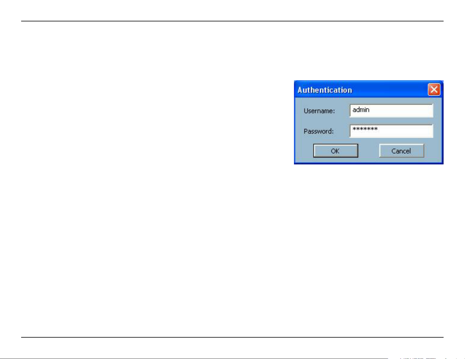
Logging In
You need to login the rst time when you start the Launcher. The authentication window is shown below. If you do not
have an account, the monitor tool will not execute. You must log in as admin (administrator) to use this application.
Enter the password for the administrator.
Note: The password is the one you provided during installation.
The Admin Privilege
In the Monitor program, the admin has the right to access the DCS-3420 Network Camera through this application
software and change the local settings as well. But the admin password for the software is not the same as the admin
password for the Internet camera. You can change the settings of each selected Internet camera from the Monitor
program only if you have the admin password for the Internet camera.
If you have the admin privilege, you have the right to do the following tasks:
• Run the conguration tool
• Change the recording schedule
• Change the local settings
Again, if you need to change the settings of the DCS-3420, you must have the administrator’s password for the camera
itself.
77D-Link DCS-3420 User Manual
Page 78

Section 3 - Configuration
Camera Configurations
When you log in for the rst time, you should congure this application software to connect the DCS-3420 in “Conguration
Menu > Camera Congurations”, shown in the gure below. You will need the admin (administrator) password of the
camera in order to run the conguration.
Once you click “Conguration Menu > Camera Congurations” for setting each camera, all recording processes will
be stopped indicated by a warning window popped up in advance to keep you informed.
78D-Link DCS-3420 User Manual
Page 79
Section 3 - Configuration
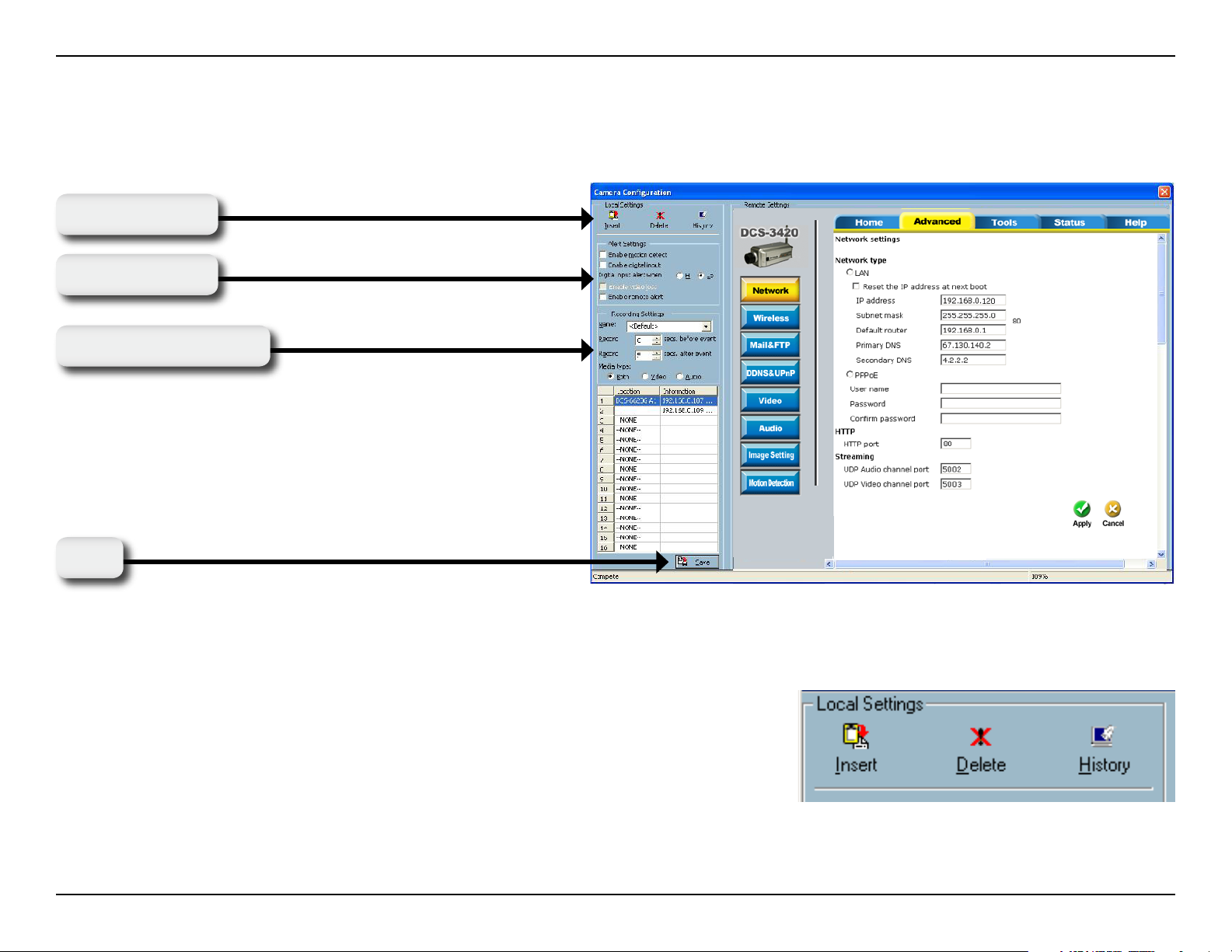
The Layout of the Configuration
This section discusses the local settings for the connection and the functional conguration of each camera. If you are
interested in the remote settings for each camera, you can refer to “Using the DCS-3420 with an Internet Browser”
(page 30).
Load Settings
Alert Settings
Recording Settings
Save
In the local settings, shown below, three main functionalities are provided:
Insert:
Delete:
History:
Click to insert a new camera to the list.
Click to delete a camera from the list.
Click to view the history of all cameras in the list.
79D-Link DCS-3420 User Manual
Page 80
Section 3 - Configuration
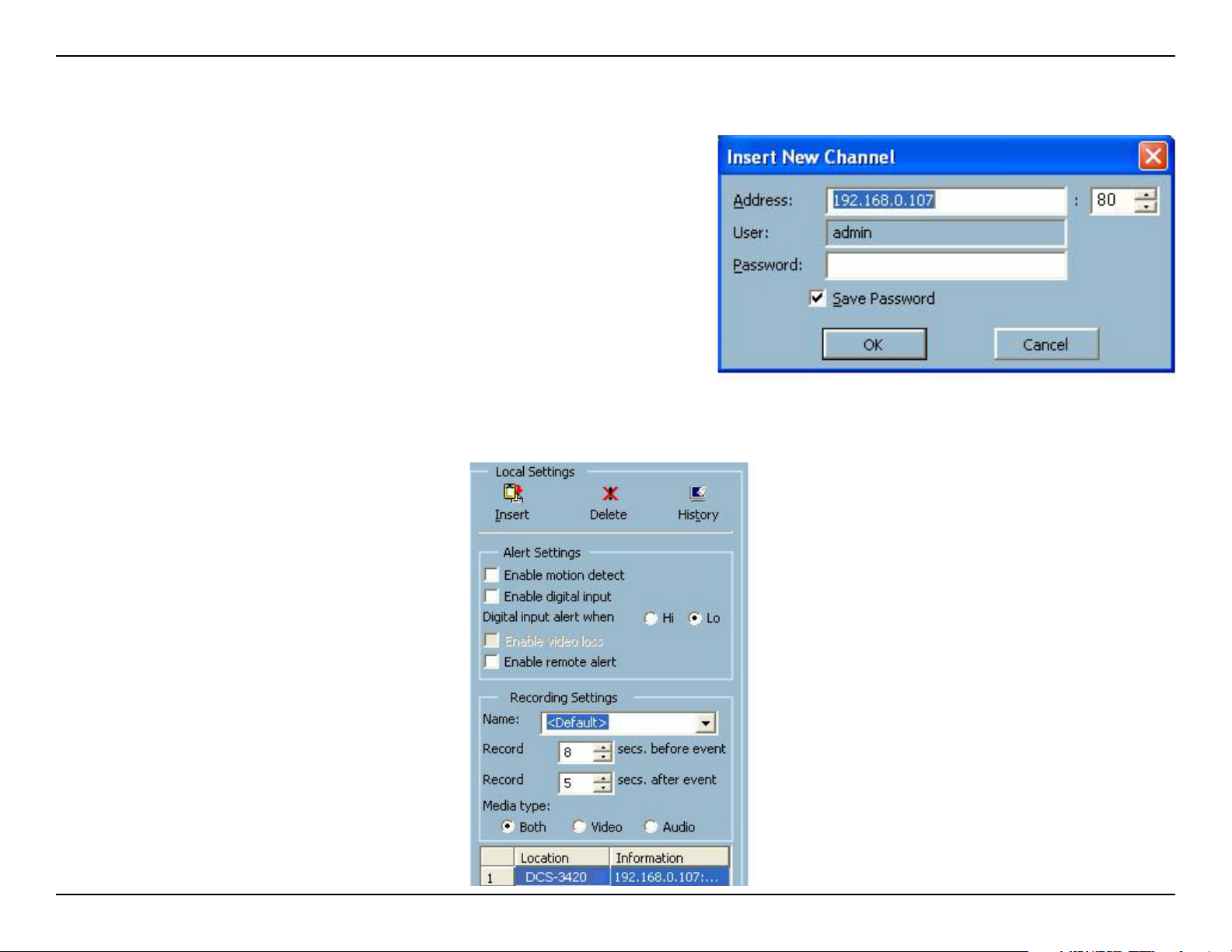
Insert
To insert a remote network camera to the camera list. Click the Insert
button, an “Insert New Channel” dialog will popup, as shown here.
Specify the IP address, port, and admin password of the network
camera, click the OK button to close the dialog. Then the system will
try to connect to the selected camera. If the connection succeeds,
the camera will be inserted to the camera selection list.
Once the camera is added, you will see the IP address of the camera and also the port that is opened on the
camera (port 80 in this example). The selected camera has been added to the selection list.
80D-Link DCS-3420 User Manual
Page 81

Section 3 - Configuration
Delete
Highlight the camera that you want to delete from the list and click on the Delete button. The selected camera will be
deleted. It removes the selected network camera from the camera list.
History
Clicking the History button will popup a historical camera list, which lists the latest 16 cameras you have inserted into
the camera list. Clicking on one camera in the history list will insert the camera into the camera list. The history list is
shown here.
81D-Link DCS-3420 User Manual
Page 82

Section 3 - Configuration
Alert and Recording Settings
Alert Settings
Specic alert actions can be performed by setting the options in this window.
Enable motion detect:
Enable digital input:
Digital input alert:
This will trigger an alert sound that has been specied in the section titled “Display & UI Settings\Local
Alert Settings”. Check this option to enable audio alerts for the selected camera.
This function is similar to “Enable Motion Detect” mentioned above. Once this option has been checked,
a digital input device will be able to trigger an alert sound and recording.
This application software provides options for you to dene the triggering criteria for the digital input of
the camera. The alert of the digital input can be dened as high-level triggered or low-level triggered.
82D-Link DCS-3420 User Manual
Page 83

Section 3 - Configuration
Recording Settings
Record # secs before event:
Record # secs after event:
Media Type:
Once the automatic video recording has been activated, you can change this setting to regulate the
recording of triggered events. Recording will start from the specied number of seconds before the alert
event has been invoked.
Recording will last for the specied number of seconds after the alert event has been invoked.
You can specify which media type you want to record: Video, Audio, or both.
Changing the Camera Order in the List
You can “drag and drop” in the grid area of the camera list to change the sequence of the connected Network Cameras,
which is shown below. This will allow you to rearrange the cameras in an order of your choice. Once the camera is
moved to a specied location, the proceeding cameras will then move 1 position up or 1 position down depending on
which direction the selected camera was moved.
Press and hold the left mouse button at the gray index eld of the camera you would like to move.
83D-Link DCS-3420 User Manual
Page 84
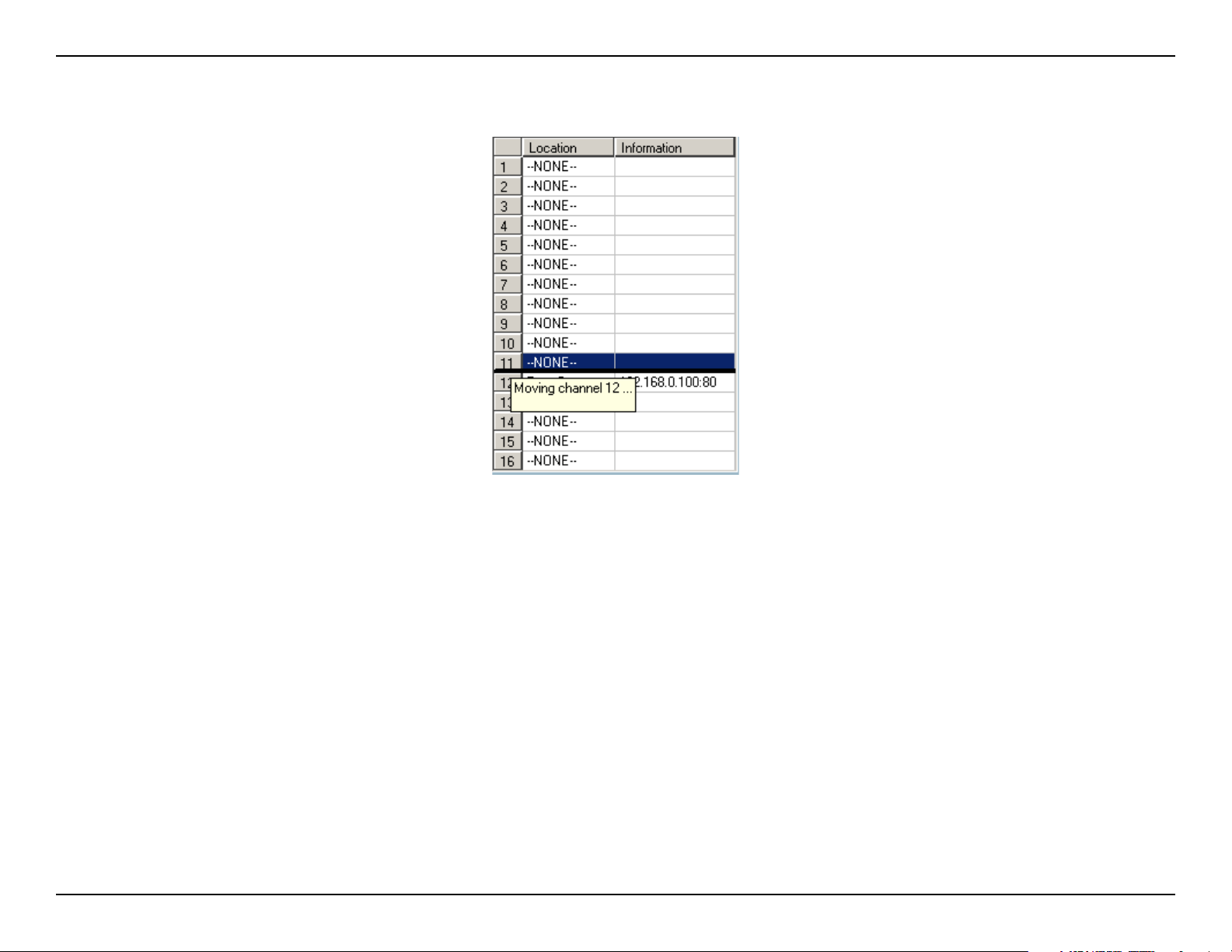
Section 3 - Configuration
Drag the mouse to your new selected location and release the mouse button. Then Video 1 will be moved (to the 12th
row in this example).
Once you click the Save button in the left-bottom corner of this window, the changes for all camera congurations will
be saved and will be applied immediately to the IP surveillance.
84D-Link DCS-3420 User Manual
Page 85

Section 3 - Configuration
Global Settings
After completing the connection to each remote Network Camera, we need to congure the global settings for all the
cameras. These include the video database directory, the usage of the Hard disk, and options for video display.
You can activate the global settings window from “Configuration Menu > Global Settings...” shown above.
All recording processes will be stopped when activating the global settings window, indicated by a warning window
popped up in advance to keep you informed.
85D-Link DCS-3420 User Manual
Page 86

Section 3 - Configuration
Directory Settings
Snapshot directory:
Recording directory:
Scheduler directory:
Cycle Recording:
Reserved space:
The directory for storing snapshots in *.bmp format from video channels of the monitor tool and playback
programs.
The directory for storing the recorded video data from video channels.
The directory for storing the default and user-customized schedules for the scheduled recording of each
channel.
Record Diskspace Usage Settings
When you turn this setting on, the video database system of this application will overwrite the oldest
data if the specied path has become full. That means it will record video data in a loop. If this setting
is unchecked, all recording will stop when the limit of the hard disk usage is reached.
Indicate the size of the hard disk that will be reserved for other Windows® applications (at least 300MB).
The remainder of the hard disk space will be available for recording. The more space you have reserved,
the less there will be available for your camera(s) to record to. As you move the bar to the right, more
space will be available for your camera(s) and conversely, less space will be available for your other
applications. If the recording data exceeds this limitation, the new video data will replace the oldest data
(on a First In First Out (FIFO) basis) when “Cycle Recording” has been checked.
86D-Link DCS-3420 User Manual
Page 87

Section 3 - Configuration
Display & UI Settings
Alert Sound:
Modulation Mode:
You can load a custom *.wav le for the alert triggering sound, or you can select a sound le from the Windows®
sound le directory.
You must select the input signal format (NTSC or PAL) for displaying the original resolution of video stream
from DCS-3420.
87D-Link DCS-3420 User Manual
Page 88

Section 3 - Configuration
Display Options
In the video displaying frame of each channel, there are two status bars. The upper bar contains “Location” (channel
number + camera name) and “Remote Time.” The lower bar contains “Connection Time” (Day:Hour:Min) and “Recording
time” (Day: Hour:Min). All of them, shown in the gure below, can be enabled or disabled here individually for the
status indication. Apply to full screen mode can also be turned on here. Once it has been checked, the status bar in
each channel showing date, location, connection, and recording time will be shown in both display frame mode and
full screen mode.
0 day 00:01
88D-Link DCS-3420 User Manual
Page 89

Section 3 - Configuration
Using the Scheduler
This section discusses the method of how to use the scheduler.
The scheduler allows the user to schedule recordings from the selected video channel of the DCS-3420. Through both
the graphic user interface and time period selection options, you will be able to easily regulate a schedule for each
video channel.
The main features of the scheduling tool are:
• Friendly graphic user interface for schedule editing
• Flexible schedule scheme suitable for all applications
• Individual schedule for each video channel
• Automatic recording
89D-Link DCS-3420 User Manual
Page 90
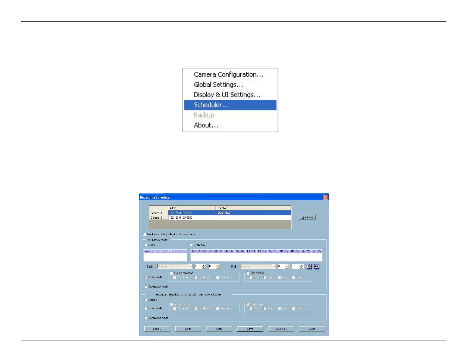
Section 3 - Configuration
Start the Scheduler
The scheduler will not be accessible until at least one camera has been added to the camera list. Go to the conguration
menu and click on Scheduler to launch the Scheduler.
The Layout and Functionalities
Introduction
The layout of the scheduler and its components, shown below, will be described. The layout of the scheduler is roughly
divided into 4 parts: Video Channel Selection Area, Primary schedule settings, Secondary schedule settings, and
Operation Buttons.
90D-Link DCS-3420 User Manual
Page 91
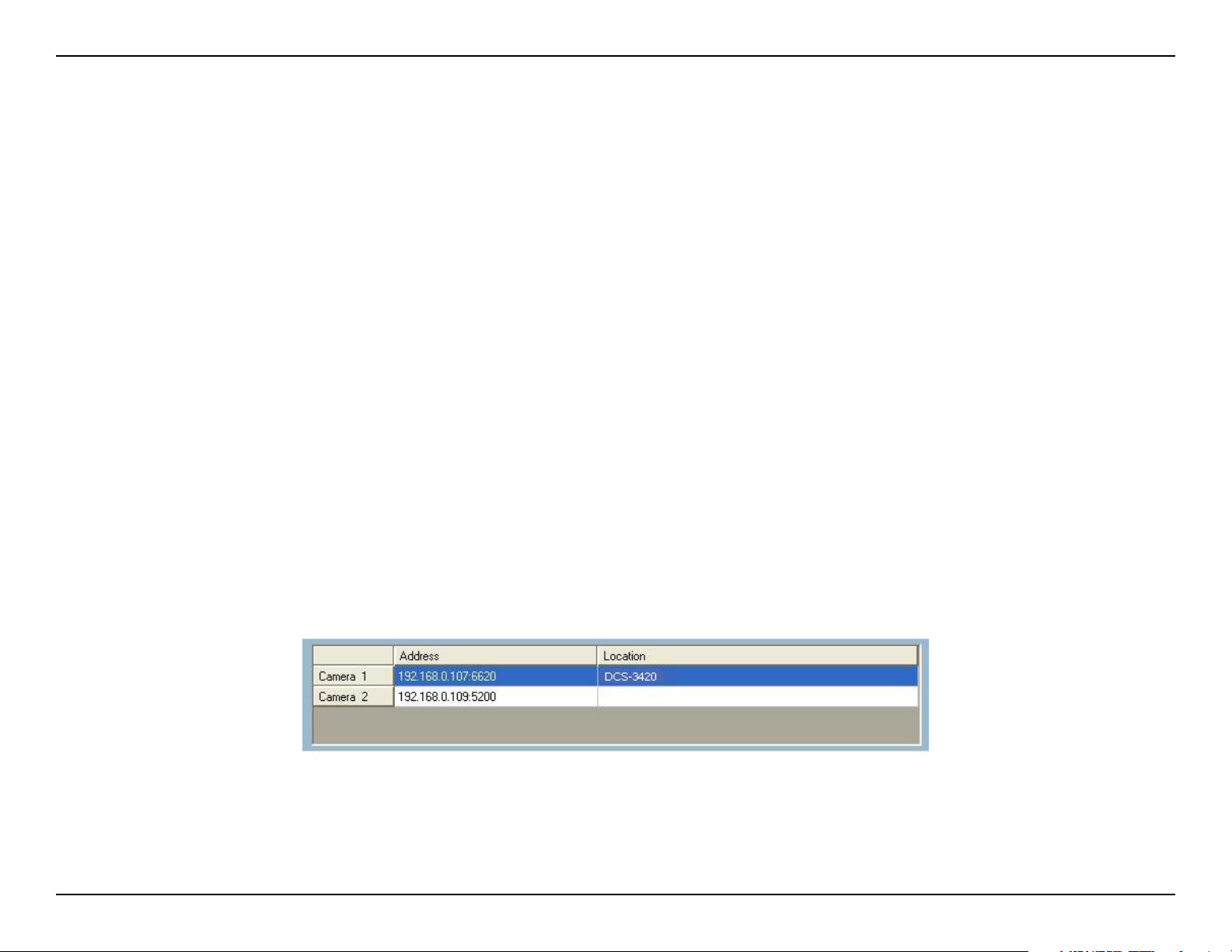
Section 3 - Configuration
Video Channel Selection Area:
Primary Schedule:
Secondary Schedule:
Operation Buttons:
The video channel selection area provides the IP addresses and location information of the connected
video channels for the user’s reference. You can select a video channel in this area and create a
schedule for it.
The Primary schedule consists of the day time-line, week time-line, begin time selector, end time selector,
and event mode settings.
The Secondary schedule consists of event mode settings.
The operation buttons allow the user to manipulate the edited schedule of the selected video channel.
The scheduler can be closed from here.
The Functionalities of Configuration Components
The four main parts of the scheduler have been briey described above. The four parts will be described in detail in
the following section.
Video Channel Selection Area
In this area you will select the video channel that you want to set a schedule for. Each video channel will display a
name, an IP address, and the location. Please note that when you switch between video channels in this area, the
changes in the schedule of the previous video channel will be saved automatically.
91D-Link DCS-3420 User Manual
Page 92

Section 3 - Configuration
Primary Schedule
Schedule with Time Lines
There are two different time-lines: hour time-line and week time-line. You can make your own schedule by plotting markers
in all time-lines. These two time lines are associated with each other. That is, if you make changes in one time-line, the
corresponding changes will be applied with scale to the other three time-lines in the same schedule. Before you begin,
make sure that you select “Once” if you want to choose the days to record on.
Week Time-Line
In the gure below, Week time-line is displayed. It includes the time-line, schedule information, and the selected day
in the week.
Marking/Unmarking the Recording Time on the Week Time-Line
The corresponding changes for the markers on the week time-line will be automatically added to the hour time-lines,
which is shown above. You can also mark and unmark the plotted bar by clicking and dragging with the left and the
right mouse button.
Hour Time-Line
In the gure below, the Hour time-line is displayed.
92D-Link DCS-3420 User Manual
Page 93

Section 3 - Configuration
Marking/Unmarking the Recording Time on the Hour Time-Line
You can apply the one-click function by clicking the left mouse button and dragging to mark the time on this time-line.
The operating method for the hour time-line is the same as that of the week time-lines. Please refer to the previous
section about marking/unmarking on the week time-line for more details.
Schedule with Time Picker
Begin and End Time
There are three controlling units in both “Begin Time” and “End Time” selectors shown below. The rst unit of these two
selectors is the date picker. You can select day with it to set the beginning time and the ending time for the recording
interval.
The second and third units are the hour picker and the minute picker. You can change the hour and minute settings
for the beginning and ending time with them.
Note: The time set in “Begin time” must be earlier than that in “End time”. Otherwise the settings will not be applied.
Apply and Erase Buttons
After you have selected the time period with “Begin time” and “End time” picker, you can apply the period picker, shown
in the gure below, to set the periodical types of the time interval set previously. After the settings in “Begin Time”, “End
Time” and “Period Picker” are all done, you should click the “Apply” button or “Erase” button on the right to add or clear
this scheduling information to the editing schedule scheme. Note that only after you click on the “Apply” button, the
scheduling information settings will be written back into the whole editing schedule scheme. That means this edited
scheduling time interval is valid only after you “Apply” the changes.
93D-Link DCS-3420 User Manual
Page 94

Section 3 - Configuration
Schedule in Event Mode
You can select to record in Event mode or Continuous mode by the Schedule mode selector as shown in the gure
below. There are two types of event recording. Please refer to the following two sections for more information.
Motion Detection
As shown below, you can check the windows that you would like to record while the motion detection is triggered.
Digital Input
In the gure below, there are four conditions for the digital input. Check the condition that you would like to record
while the condition triggers.
94D-Link DCS-3420 User Manual
Page 95

Section 3 - Configuration
High:
Low:
Rising:
Falling:
Checking this will trigger recording while the digital input is high. The technical name for this event is line trigger.
Checking this will trigger recording while the digital input is low. The technical name for this event is line trigger.
Checking this will trigger recording while the digital input is changing from low to high. The technical name for this
event is edge trigger.
Checking this will trigger recording while the digital input is changing from high to low. The technical name for this
event is edge trigger.
Schedule in Continuous mode
If you select Continuous mode in the schedule mode selector, it will record continuously during the schedule that is
set up by the user.
Secondary Schedule
Secondary schedule is for recording outside of the primary schedule. The secondary schedule provides options to
record without a specied date or time.
Schedule modes
There are three modes in the secondary schedule: Disable, Event mode, and Continuous mode. If event mode is
selected in the secondary schedule, the camera will record whenever an event is triggered. If continuous mode is
selected, the camera will begin recording continuously after scheduling settings are saved. These two modes are the
same as the primary schedule. Please refer to the previous section for more detail.
95D-Link DCS-3420 User Manual
Page 96

Section 3 - Configuration
Operation Buttons
There are six operation buttons that allow you to handle the schedule schemes: “Load…”, “Undo”, “Clear”, “Save”,
“Save as…” and “Close.” These operation buttons are shown in the gure below.
Load:
Undo:
Clear:
Save:
Save As...:
Close:
This button allows you to load pre-edited schedules from the scheduling directory for the selected video
channel. Note that you should save the schedule you are currently working on before loading a new
one. Otherwise, the current changes will be lost.
Click on this button to undo all changes for the current schedule since the last save.
This button will clear all changes in the current schedule of the selected video channel.
This button is used for saving changes to the current schedule.
This button is used to save the current schedule as another le name instead of the default name.
Click on this button to close the scheduler.
96D-Link DCS-3420 User Manual
Page 97
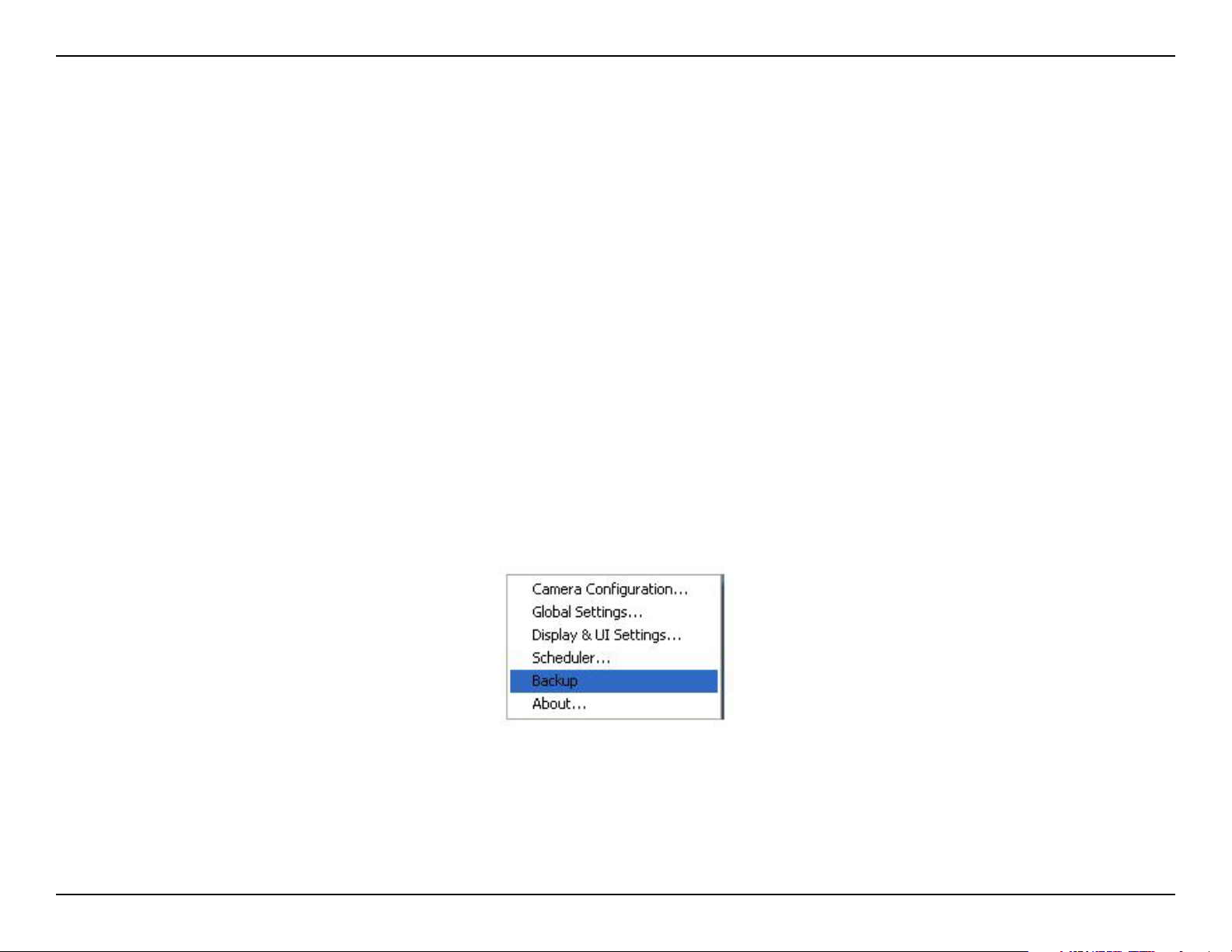
Section 3 - Configuration
Backup Settings
Using Backup Settings in the global settings window, you can backup recorded data from selected cameras to a
specied location.
Directory:
This is the directory where backup data will be saved. You can select the location by
clicking on the folder icon.
Size:
You can set the size limit of the data that will be backed up. The default size limit is 10MB.
The maximum value for this setting depends on the amount of Free Space available on
your hard drive. This value can be found under the “Record Disk space Usage Settings”
section of the global settings window.
Backup Location Select:
Select the locations to backup by clicking the checkbox next to the location/camera name.
To delete a location, select the location and click the “Delete” button to the right of the
Backup Location Select window.
After you have set your backup settings in the global settings window, you can backup recorded data by clicking
“Backup” in the Conguration Menu, as seen below:
97D-Link DCS-3420 User Manual
Page 98

Section 3 - Configuration
Using the Monitor Program
This section depicts, in detail, how to manipulate the monitor tool.
Connection of the DCS-3420
Once you have the privilege to connect to the DCS-3420, the cameras will automatically appear in the video area in
the order they are connected. Once you have set up the camera in the video channel, the color of the channel number
will turn green, indicating that the camera has been added to IP surveillance. If you do not set up the camera for the
video channel, the color of the channel number will be gray.
There is a unique light signal associated with each channel number. It indicates the status of the dedicated video
channel, which is depicted as follows:
The video channel is not connected with any DCS-3420 yet.
Off:
Green:
Blink:
The green light means the DCS-3420 associated with this channel number is connected, and the video is monitored
in the video area.
The red light indicates the video from this channel is recording into the video database. In this mode, you don’t have
Red:
to drag and drop the channel to the video area. This means that this application software supports real-time recording
with and without real-time monitoring for the dedicated video channel.
With the motion detection mechanism set in the DCS-3420, the light of the corresponding channel
will blink once the motion event is triggered.
If you do not want to monitor one video, you can drag and drop the video (in the video area) to the
trash can in the common control area of the monitor program. The following section will demonstrate
the procedures for “drag and drop” step-by-step.
98D-Link DCS-3420 User Manual
Page 99

Section 3 - Configuration
Show the video of a specified channel
This section depicts the method of how to show the video of a specic channel in a display window.
Step 1: Move the mouse cursor to the camera you would like display in the window.
Step 2: Press and hold the left mouse button, and then drag it to a display window in the video area on the right side
of the screen. Note that the cursor will change according to the area in order to indicate whether the area is droppable
or not.
Step 3: Release the left mouse button while on top of a display window. The video will appear in the display window
as shown below. In each display layout, only one window can be assigned to a camera. Also, each camera must have
its own separate window when displayed. Once the video is in a display window, it can be dragged and dropped to
other windows. If you drag one camera’s video to a window that already has its own camera’s video, the two cameras
will trade display windows. Dragging and dropping is a very convenient way to manipulate the video channels in the
IP surveillance Software.
99D-Link DCS-3420 User Manual
Page 100
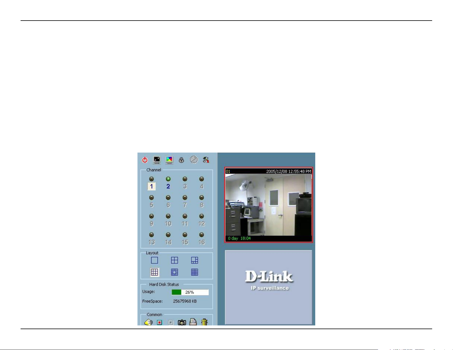
Section 3 - Configuration
Removing video from a display window
Step 1: Move the mouse cursor to the display window that contains the video channel you wish to remove.
Step 2: Note that the cursor will change to the hand-shape when it has been moved onto the displaying frame. After
that, press the left mouse button and hold it.
Step 3: Move the cursor, while still holding the left mouse button, to the trash can in the common area of the monitor
program.
Step 4: When the cursor shape changes to an arrow-shape over the trash can, release the left mouse button. The video
in the corresponding display window will disappear. All operations above are shown in the gure on the following
100D-Link DCS-3420 User Manual
 Loading...