


Cissell L44FD42, L36US36, L36UR30, L50CD42, L36US30 User Manual
...

IMPORTANTNOTICES—PLEASEREAD
For optimum efficiency and safety, we recommend that you read the Manual before operating the equipment. Store this manual in a file or binder and keep for future reference.
WARNING: For your safety, the information in this manual must be followed to minimize the risk of fire or explosion or to prevent property damage, personal injury, or loss of life.
-Do not store or use gasoline or other flammable liquids or vapors in the vicinity of this or any other appliance.
-WHAT TO DO IF YOU SMELL GAS
•Do not try to light any appliances.
•Do not touch any electrical switch; do not use any phone in your building.
•Clear the room, building, or area of all occupants.
•Immediately call your gas supplier from a neighbor's phone. Follow the gas supplier's instructions.
•If you cannot reach the gas supplier, call the fire department.
Installation and service must be performed by a qualified installer, service agency or the gas supplier.
WARNING: In the event the user smells gas odor, instructions on what to do must be posted in a prominent location. This information can be obtained from the local gas supplier.
WARNING: Wear Safety Shoes to prevent injuries.
WARNING: Purchaser must post the following notice in a prominent location:
FOR YOUR SAFETY
Do not store or use gasoline or other flammable vapors and liquids in the vicinity of this or any other appliance.
WARNING: A clothes dryer produces combustible lint and should be exhausted outside the building. The dryer and the area around the dryer should be kept free of lint.
WARNING: Be safe, before servicing machine, the main power should be shut off.
Page 2

WARNING: To avoid fire hazard, do not dry articles containing foam rubber or similar texture materials. Do not put into this dryer flammable items such as baby bed mattresses, throw rugs,undergarments (brassieres, etc.) and other items which use rubber as padding or backing. Rubber easily oxidizes causing excessive heat and possible fire. These items should be air dried.
WARNING: Synthetic solvent fumes from drycleaning machines create acids when drawn through the dryer. These fumes cause rusting of painted parts, pitting of bright or plated parts, and completely removes the zinc from galvanized parts, such as the tumbler basket. If drycleaning machines are in the same area as the tumbler, the tumbler's make-up air must come from a source free of solvent fumes.
WARNING: Do not operate without guards in place.
WARNING: Check the lint trap often and clean as needed but at least a minimum of once per day.
WARNING: Alterations to equipment may not be carried out without consulting with the factory and only by a qualified engineer or technician. Only Cissell parts may be used.
WARNING: Remove clothes from dryer as soon as it stops. This keeps wrinkles from setting in and reduces the possibility of spontaneous combustion.
WARNING: Be Safe - shut main electrical power and gas supply off externally before attempting service.
WARNING: Never use drycleaning solvents, gasoline, kerosene, or other flammable liquids in the dryer.
FIRE AND EXPLOSION WILL OCCUR. NEVER PUT FABRICS TREATED WITH THESE LIQUIDS INTO THE DRYER. NEVER USE THESE LIQUIDS NEAR THE DRYER..
WARNING: Never let children play near or operate the dryer. Serious injury could occur if a child should crawl inside and the dryer is turned on.
WARNING: Never tumble fiberglass materials in the dryer unless the labels say they are machine dryable. Glass fibers break and can remain in the dryer. These fibers cause skin irritation if they become mixed with other fabrics.
WARNING: Before operating gas ignition system - purge air from Natural Gas or Propane Gas Lines per manufacturer’s instructions..
Page 3
CISSELLDRYERWARRANTY
The Cissell Manufacturing Company (Cissell) warrants all new equipment (and the original parts thereof) to be free from defects in material or workmanship for a period of two (2) years from the date of sale thereof to an original purchaser for use, except as hereinafter provided. With respect to non-durable parts normally requiring replacement in less than two (2) years due to normal wear and tear, and with respect to all new repair or replacement parts for Cissell equipment for which the two (2) year warranty period has expired, or for all new repair or replacement parts for equipment other than Cissell equipment, the warranty period is limited to ninety (90) days from date of sale. The warranty period on each new replacement part furnished by Cissell in fulfillment of the warranty on new equipment or parts shall be for the unexpired portion of the original warranty period on the part replaced.
With respect to electric motors, coin meters and other accessories furnished with the new equipment, but not manufactured by Cissell, the warranty is limited to that provided by the respective manufacturer.
Cissell’s total liability arising out of the manufacture and sale of new equipment and parts, whether under the warranty or caused by Cissell’s negligence or otherwise, shall be limited to Cissell repairing or replacing, at its option, any defective equipment or part returned f.o.b. Cissell’s factory, transportation prepaid, within the applicable warranty period and found by Cissell to have been defective, and in no event shall Cissell be liable for damages of any kind, whether for any injury to persons or property or for any special or consequential damages. The liability of Cissell does not include furnishing (or paying for) any labor such as that required to service, remove or install; to diagnose troubles; to adjust, remove or replace defective equipment or a part; nor does it include any responsibility for transportation expense which is involved therein.
The warranty of Cissell is contingent upon installation and use of its equipment under normal operating conditions. The warranty is void on equipment or parts; that have been subjected to misuse, accident, or negligent damage; operated under loads, pressures, speeds, electrical connections, plumbing, or conditions other than those specified by Cissell; operated or repaired with other than genuine Cissell replacement parts; damaged by fire, flood, vandalism, or such other causes beyond the control of Cissell; altered or repaired in any way that effects the reliability or detracts from its performance, or; which have had the identification plate, or serial number, altered, defaced, or removed.
No defective equipment or part may be returned to Cissell for repair or replacement without prior written authorization from Cissell. Charges for unauthorized repairs will not be accepted or paid by Cissell.
CISSELLMAKESNOOTHEREXPRESSORIMPLIEDWARRANTY,STATUTORYOROTHERWISE,CONCERNING THEEQUIPMENTORPARTSINCLUDING,WITHOUTLIMITATION,AWARRANTYOFFITNESSFORAPARTICULAR PURPOSE, OR A WARRANTY OF MERCHANTABILITY. THE WARRANTIES GIVEN ABOVE ARE EXPRESSLY IN LIEU OF ALL OTHER WARRANTIES, EXPRESS OR IMPLIED. CISSELL NEITHER ASSUMES, NOR AUTHORIZES ANY PERSON TO ASSUME FOR IT, ANY OTHER WARRANTY OR LIABILITY IN CONNECTION WITH THE MANUFACTURE,USEORSALEOFITSEQUIPMENTORPARTS.
For warranty service, contact the Distributor from whom the Cissell equipment or part was purchased. If the Distributor cannot be reached, contact Cissell.
IDENTIFICATIONNAMEPLATE
The Identification Nameplate is located on the rear wall of the dryer. It contains the dryer serial number, product number, model number, electrical specifications and other important data that may be needed when servicing and ordering parts, wiring diagrams, etc. Do not remove this nameplate.
Page 4
TABLE OF CONTENTS
110 LB. LAUNDRY DRYER
INSTALLATION/OPERATIONMANUAL
|
PAGE |
Model Numbers & Company Address................................................................................. |
1 |
ImportantNotices ............................................................................................................. |
2-3 |
Dryer Warranty ................................................................................................................... |
4 |
Table of Contents ................................................................................................................ |
5 |
Warnings, Cautionary Notes and Symbols........................................................................ |
6-7 |
Unpacking and General Insulation ....................................................................................... |
8 |
Disassembling Top of Dryer ............................................................................................... |
9 |
Gas Heated Dryer Illustration ........................................................................................... |
10 |
Steam Heated Dryer Illustration ........................................................................................ |
11 |
Electric Dryer Illustration ................................................................................................. |
12 |
Gas Fired Dryer Illustration .............................................................................................. |
13 |
Specifications............................................................................................................... |
14-16 |
Electrical Connections ...................................................................................................... |
17 |
Gas Piping ......................................................................................................................... |
18 |
Gas Piping and Gas Loop Piping Installation .................................................................... |
19 |
Gas Pipe Size Chart .......................................................................................................... |
20 |
Gas Piping Installation ...................................................................................................... |
21 |
Steam Piping Installation .............................................................................................. |
22-23 |
Exhaust Installation - Multiple Manifold Duct ............................................................. |
24-26 |
Exhaust Installation with Separate Exhaust ....................................................................... |
27 |
Dryer Air Flow Installation............................................................................................... |
28 |
Rules for Safe Operation ................................................................................................... |
29 |
Energy Saving Tips ........................................................................................................... |
30 |
Two Timer Model Operation Instructions .................................................................... |
31-33 |
Service Savers .................................................................................................................. |
34 |
Troubleshooting ........................................................................................................... |
35-38 |
Page 5

SYMBOLS
The following symbols are used in this manual and/or on the machine. The numbers between () refer to the numbers on the machine surveys.
Symbol |
Description |
Part/Measurement |
NOTE!
Hot! Do Not Touch
Heiß! NichtBeruhren Haute temperature! Ne pas
toucher Caliente! no tocar
dangerousvoltage tensiondangereuse Gefährliche elektrische
Spannung
tension peligrosa
on marche Ein conectado
off arrêt Aus
desconectado
start demarrage Start
arranquedeunmovimiento
emission of heat in general êmission de chaleur en general
Warmeabgabeallgemein emisión de calor
cooling refroidissement Kühlen enfriamiento
Page 6

SYMBOLS
Symbol |
Description |
Part/Measurement |
rotationintwodirections rotationdanslesdeuxsens DrehbewigunginzweiRichtungen movimientorotativoenlosdos
sentidos
direction of rotation
sens de mouvement continu de rotation DrehbewegunginPfeilrichtung movimiento giratorio o rotatorio
en el sentido de la flecha
End of Cycle
caution attention Achtung
atencion;precaucion
Page 7

Unpacking/General Installation (All Dryers)
UNPACKING
GENERAL INSTALLATION(ALL DRYERS)
All Cissell dryers are packed in a protective (heavy-duty) plastic bag.
Upon arrival of the equipment, any damage in shipment should be reported to the carrier immediately.
Upon locating permanent location of a unit, care should be taken in movement and placement of equipment.
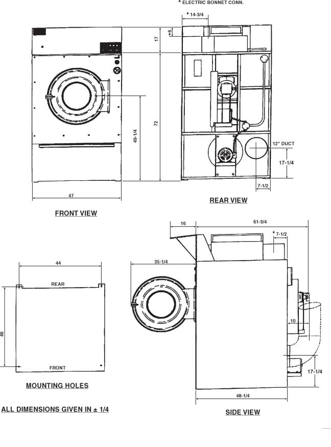
See outline clearance diagrams for correct dimensions.
Remove all packing material such as: tape, manuals, skid, etc. On gear reducer models, remove screw and insert vent found in basket.
Leveling: Use spirit level on top of dryer. Adjust leveling bolts on dryer (see adjustable leveling bolts in maintenance section).
Check voltage and amperes on rating plate before installing the dryer.
The construction of Cissell dryers permits installation side-by-side to save space or to provide a wall arrangement. Position dryer for the least amount of exhaust piping and elbows, and allow free access to the rear of dryer for future servicing of belts, pulleys and motors. Installation clearance from all combustable material is 12” ceiling clearance, 24” rear clearance, and 0” side clearance.
Before operating dryer, open basket door and remove blocking between front panel and basket. Read the instruction tags, owner's manual, warnings, etc.
IMPORTANT
Openingtheclothesloadingdoordeactivatesthedoorswitch to shut off the motors, fan, gas, steam, or electric element. To restart the dryer, close the door and press in the push to start buttonandholdbriefly.
IMPORTANT
This dryer is designed for a capacity maximum load. Overloadingitwillresultinlongdryingtimesanddampspots on some clothes.
IMPORTANT
Maximumoperatingefficiencyisdependentuponproperair curculation. The lint screen must be kept cleaned daily to insure proper air circulation throughout the dryer.
IMPORTANT
Provideadequateclearanceforairopeningintothecombustion chamber.
Page 8

Disassembling Top of Dryer
PROCEDUREFOR DISASSEMBLING TOP OF 110 LB. GAS LAUNDRY DRYERS
1.Shut off main gas supply and electrical power. Disconnect bonnet gas supply line at union fitting.
2.Unscrew two (2) top front cover panel hold down screws and open front cover panel. If wires enclosed are not color coded or number matched, match mark before disconnecting or removing.
3.In the left hand control box, disconnect the two (2) multi-wire connector plugs. Unscrew two (2) hold down bolts from the bottom of the box and one (1) bolt outside the rear of the box. Remove the two (2) screws that hold the conduit plate to the control box. Now remove the box.
4.In the right hand control box, unscrew one (1) screw at the top of the control panel and swing panel forward. Disconnect two (2) multi-wire connector plugs. Unscrew two (2) hold down bolts from bottom of box and one (1) bolt outside the box at the rear.
5.Replace two (2) top front cover panel hold down screws and remove entire control panel assembly.
6.Disconnect exhaust duct at bonnet enclosure assembly. (Only applies to energy-saver models “F” and “R”.)
7.Unscrew hold down screws from bonnet enclosure assembly (energy-saver models only). Unscrew bonnet hold down bolts. Remove air switch box cover on rear of dryer, disconnect one (1) yellow wire from air switch, one (1) black wire at cigarette connector and remove one (1) conduit nut. The entire bonnet and enclosure assembly can now be removed from top of dryer.
8.To reassemble, reverse disassembly procedure.
Page 9

110 lb. Gas Fired Dryer—Models L44CD42G and L44KD42G (Illustration)
Page 10
110 lb. Steam Heated Dryer—Models L44CD42S and L44KD42S (Illustration)
Page 11
110 lb. Electric Dryer—Model L44CD42E (Illustration)
Page 12
 Loading...