


IPSO - LSG n.v.
Instruction manual
HF150 HF185
HF234
Technical specifications
Installation instructions
Operating instructions
Maintenance
Nieuwstraat 146 - B-8560 Wevelgem (België)
Tel. 056/41 20 54 - Fax 056/41 86 74

Contents |
|
|
1 |
General safety instructions .......................................................................... |
3 |
2 |
Technical data and dimensions ................................................................... |
4 |
|
Technical data .................................................................................................. |
4 |
|
Dimensions....................................................................................................... |
6 |
3 |
Installation and connection .......................................................................... |
8 |
|
Ground ............................................................................................................. |
8 |
|
Removal of the transport safety ....................................................................... |
8 |
|
Water connection ............................................................................................. |
8 |
|
Water drain....................................................................................................... |
9 |
|
Main power connection .................................................................................... |
9 |
|
Liquid soap connection..................................................................................... |
10 |
|
Connection of a central operating panel for coinmachines (option) ................. |
11 |
|
Steam connection............................................................................................. |
12 |
4 |
Operating instructions ................................................................................. |
13 |
|
Machine with start button ................................................................................ |
13 |
|
Machine with coin or token operation............................................................... |
21 |
5 |
Standard programs ...................................................................................... |
27 |
6 |
Technical remarks ........................................................................................ |
28 |
|
Internal connection of the electrical heating..................................................... |
28 |
|
Tilt switch ......................................................................................................... |
28 |
|
Error messages................................................................................................ |
29 |
7 |
Maintenance of the machine ........................................................................ |
31 |
Code: 249/00324/20
19/12/2005
Content

1
General safety instructions
Ignoring any of the safety instructions can cause serious personal injury and can also cause damage to the linen or the machine
Read the installation and instruction manual carefully before connecting the machine.
It is recommended that the machine be installed by qualified technicians.
The machine should be installed according to the installation instructions. (See chapter 3)
The machine should be grounded according to the instructions in order to eliminate the risk of electrocution.
Do not expose the machine to high humidity or extreme high or low temperatures.
Cut off all main water inlets, steam and electrical supplies at the end of each operating day.
Before starting repairs or maintenance, shut off all power and water supplies.
To prevent fire and explosion:
Keep the area around the machine free from inflammable or combustible products.
Do not put fabrics that are treated with inflammable products into the machine. These fabrics should be hand-washed or air-dried first.
Always carefully read and follow the instructions on the packing of detergents. Store these products out of the reach of children.
Always take into account the instructions on the labels of clothes.
Never allow children to play in the surroundings of a machine.
Remark:
These instructions surely cannot prevent all risks of accidents. It is up to the user to act with the utmost precaution.
Do not hesitate to contact the dealer in case of a problem.

Technical data and dimensions |
|
2 |
|
|
|
Technical data |
|
|
|
HF150 |
HF185 |
Capacity (dry weight) |
|
|
1/11 |
13 kg |
16,4 kg |
1/10 |
14,5 kg |
18 kg |
1/9 |
16 kg |
20 kg |
Cylinder |
|
|
Diameter |
680 mm |
680 mm |
Depth |
400 mm |
500 mm |
Volume |
145 Lit |
181 Lit |
Cabinet |
|
|
Height |
1348 mm |
1348 mm |
Width |
780 mm |
780 mm |
Depth |
840 mm |
940 mm |
Front loading |
|
|
Diameter door opening |
395 mm |
395 mm |
Door height |
565 mm |
565 mm |
To center |
770 mm |
770 mm |
Speed |
|
|
Wash |
|
10 - 50 tr/min |
Distribution |
|
85 tr/min |
Low spin |
|
250 - 500 tr/min |
High spin |
|
500 - 1000 tr/min |
G-factor |
|
|
Low spin/high spin |
|
94 / 380 |
Motoren (3-fasig) |
|
|
4p. 1470 tr./min |
|
2200W |
Drain valve |
|
|
Depend-O-Drain |
|
2" |
Water supply |
|
|
Hard, soft, warm water |
|
3/4" |
Steam connection |
|
|
Steam connection |
|
3/8" |
Heating |
|
|
Electrical 230/400 V |
|
12/15/18 kW |
Electrical 400V |
|
21/24 kW |
Steam |
|
6 bar |
Warm water (without additional heating) |
X |
|
Warm water (with additional heating) |
|
X |
Packing dimensions |
|
|
(H x W x D) mm |
1495x850x930 - 1495x850x1030 |
|
Weight |
|
|
Nett |
424 kg |
454 kg |
Gross |
440 Kg |
470 kg |

2
Technical data and dimensions
Technical data
|
HF234 |
Capacity (dry weight) |
|
1/11 |
21,3 kg |
1/10 |
23,4 kg |
1/9 |
26 kg |
Cylinder |
|
Diameter |
750 mm |
Depth |
530 mm |
Volume |
234 Lit |
Cabinet |
|
Height |
1505 mm |
Width |
900 mm |
Depth |
985 mm |
Front loading |
|
Diameter door opening |
395 mm |
Door height |
630 mm |
To center |
820 mm |
Speed |
|
Wash |
10 - 50 tr/min |
Distribution |
100 tr/min |
Low spin |
250 - 500 tr/min |
High spin |
500 - 1000 tr/min |
G-factor |
|
Low spin/high spin |
74/ 373 |
Motoren (3-fasig) |
|
4p. 1470 tr./min |
3000W |
Drain valve |
|
Depend-O-Drain |
3" |
Water supply |
|
Hard, soft, warm water |
3/4" |
Steam connection |
|
Steam connection |
3/8" |
Heating |
|
Electrical 230/400 V |
12/15/18 kW |
Electrical 400V |
24 kW |
Steam |
6 bar |
Warm water (without additional heating) |
X |
Warm water (with additional heating) |
X |
Packing dimensions |
|
(H x W x D) mm |
1650x 1020x 1150 mm |
Weight |
|
Nett |
570 kg |
Brutt |
630 kg |

Dimensions
HF150 - 185
1375.5 |
1348 |
565
50 |
680 |
50 |
|
780 |
|
332 |
|
|
267 |
|
|
202 |
|
200 |
105 |
|
155 |
A |
|
F |
|
|
|
|
D |
G |
B |
|
|
C |
E |
H |
|
|
I |
|
|
|
35 |
|
|
|
L |
1141.5 |
935 |
1066.5 |
1181.5 |
|
|
|
703.5 |
|
|
|
K |
|
|
|
185 |
|
|
|
170 |
2
88 |
220 |
34 |
HF150 = 665 - HF185 = 765 |
34 |
|
HF150 = 733 - HF185 = 833 |
|
86.5 |
HF150 = 753 - HF185 = 853 |
|
A. Ventilation soap dispenser
B. Liquid soap connetions
C. Hard water connections 3/4"
D. Warm water connections 3/4"
E. Soft water connections 3/4"
F. Connections clamps
G.Electrical connections
H.Emergency button
I. Ventilation tub
K. Drain valve
L. Steam connections

Dimensions
HF234
1527.5 |
1500 |
645
81


346
 251
251
 155.5
155.5 
A
C D E
B
|
35 |
1386 |
L |
1265.5 |
|
|
720 |
738
900


 81
81
 173
173  94
94 

F
G
I
1309.5
K
165
2
60 |
240 |
H
35 |
HF234 = 830 |
35 |
 HF234 = 926
  70
70  HF234 = 939.5
A. Ventilation soap dispenser
B. Liquid soap connetions
C. Hard water connections 3/4"
D. Warm water connections 3/4"
E. Soft water connections 3/4"
F. Connections clamps
G.Electrical connections
H.Emergency button
I. Ventilation tub
K. Drain valve
L. Steam connections

 105
105
3
Installation and connection
Ground
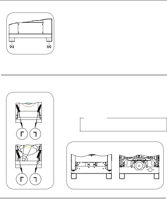
The machine must be placed on a flat, solid surface (metal base, concrete or solid ground). It is recommended that the machine be anchored on the provided places (A) in the base, especially in case of a plinth
(see Dimensions 2).
The machine must be placed entirely level. For easy maintenance it is recommended to keep a minimal distance of 600 mm between the wall and the back of the machine.
If several machines are placed next to each another, there should be a minimal distance of 30 mm between each machine.
Removal of the transport safety
HF234
To prevent damage during transportation, the machine has been equipped with four red transport brackets to eliminate every possible movement of the tub.
After the machine has been placed level, take off the serviceand the back panel to remove these transport brackets.
Important
The machine must never be activated before removing these transport brackets.
HF150-185
Water connection
The machine is delivered with hoses with 3/4" connections. These hoses fit the water inlet valves of the machine and the main water inlet taps. To ensure the optimal functioning of the water inlet valves, the water pressure on the inlet should be between 0,5 and 10 kg/cm² (7 and 145 psi). If the pressure is too low, the cycle time will increase considerably.
In case of boiler fed machines, a minimum of hot water of 90°C should be available: For the HF150: 94 l. HF185: 115 l. HF234: 150 l.
3
Water drain
The machine is equipped with a drain valve (HF150-185) with 2" outer diameter (50mm) (HF234) 3" outer diameter (80 mm). This drain valve should be connected to the drain by means of the drain elbow which is delivered with the machine.
The diameter of the main drain should be adapted to the water flow and the number of machines. It should be sufficient to handle at least 160L/min. per machine.
It is necessary to connect the main drain at least on one side to an open air-brake to allow ventilation.
When the main drain has not been sufficiently deodorized, every machine should be installed seperately with a deodorizer.
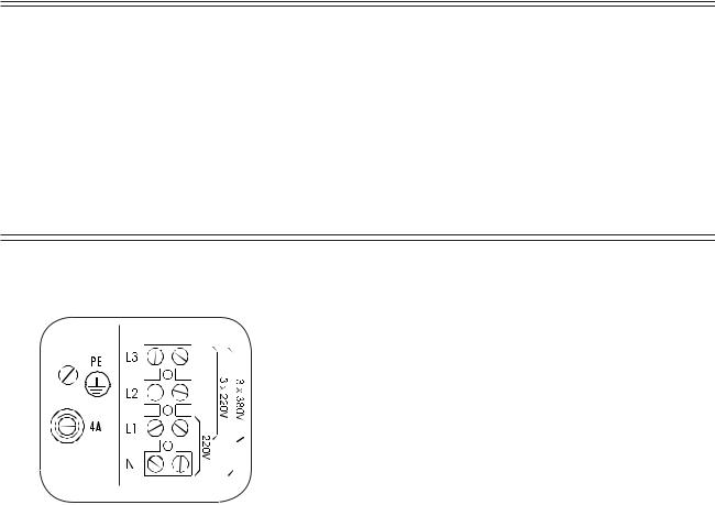
Electrical Connection
Remove the cover plate at the back of the machine. (See dimensions (E)).
Connect the power cable to the connectors.
220V 3AC
220V 3 phase (3AC) should be connected to the connectors “L1,L2,L3”.
The green/yellow grounding clamp has to be connected to the grounding wire “PE”.
380 V 3AC + N
380 V 3 phase (3AC + N) has to be connected to the connectors
“L1,L2,L3”, the blue neutral to the “N” connector.
The green/yellow grounding clamp has to be connected to the grounding wire “PE”.
After connection, check the spin direction. The cylinder must spin in the direction of the arrow, showed on the sticker on the door window (clockwise).
A wrong spin direction can damage the motor, and can also cause water to spurt from the soap dispenser.
Power of the breaker plugs:
machine with steam heating or boiler fed machines without additional electrical heating
220V 3AC 380V 3AC + N
16 A 16 A
machine with electrical heating
|
220V 3AC 380V 3AC + N |
|
9kw |
25A |
16A |
12 kW |
40 A |
20 A |
15 kW |
50 A |
25 A |
18 kW |
50 A |
32 A |
21 kW |
---- |
40 A |
24 kW |
---- |
40 A |
3
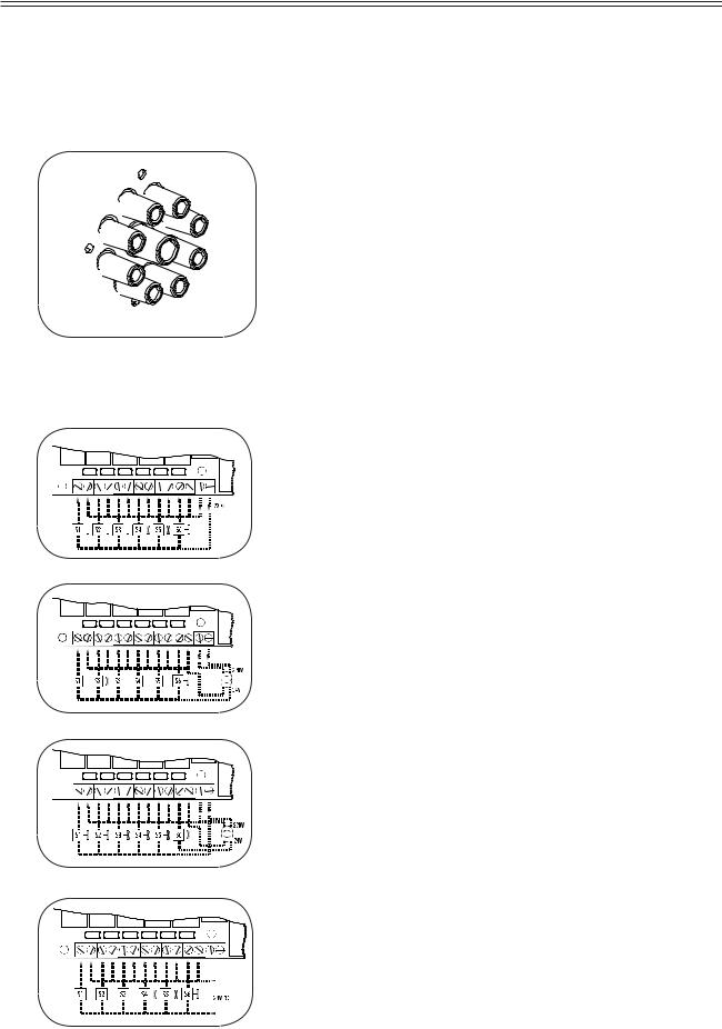
Liquid soap connection (option)
Connection of the liquid soap hoses
Electrical connection of the liquid soap pumps
The liquid soap connection consists of 8 connections for liquid soap (SI….S).
The central opening is used for ventilation.
On machines equipped with a liquid soap connection, connect the wires directly on the print board next to the ground wire connection (option). Connect as indicated on the wiring diagram.
The two connectors on the right give a tension of 220V ~ (max. 4A) which can be applied to drive 220V ~ soap pumps. If more than 4A is required, an external tension will have to be used. 6 connections have been provided, of which one (S6) can be used to drive a waterproofing pump (e.g. for rain coats, etc.).
The 220V can be transformed to other values to drive other type soap pumps.
Example: pumps 24V ~.
Also, pumps with different operating tension can be combined.
Example: 5 pumps 220V ~ and 1 pump 24V ~.
With an external tension 24V DC
 Loading...