

Page 1

Cisco SG300 Setup Guide
When used with ELAN Video Over IP products
Page 2

Cisco SG300 SETUP GUIDE
02
www.elanhomesystems.com
Contents
Introduction 03
Cisco Feature Requirements 03
Connecting To The Web GUI Interface 04
Activating Layer 3 Mode 05
Jumbo Frames 06
IGMP Snooping 07-09
Turning On/O POE 10
Apply And Save Settings 11
Changing Your Computer IP Address 12-14
Page 3

Cisco SG300 SETUP GUIDE
03
contact techsupport@elanhomesystems.com
The ELAN Video Over IP solution requires a layer 3 Managed switch in order for
HDMI distribution to be achieved reliably and with no loss in performance.
The following guide is a step-by-step instruction on how to connect and congure
your Cisco SG300 Layer 3 Managed network switch.
Introduction
The following features need to be enabled on the Cisco network switch:-
1. Layer 3 mode
2. Jumbo Frame
3. IGMP Snooping/Video Over IP
4. POE (if utilised)
Feature explanation:
• Video Over IP (one-to-many or many-to-many distribution) is group communication where information is addressed to a
group of network devices simultaneously (ELAN Video Over IP products).
• Jumbo frames are Ethernet frames with more than 1500 bytes of payload. Conventionally, jumbo frames can carry up
to 9000 bytes of payload and must be activated in order to send large packets of data for HDMI distribution.
• IGMP management & snooping is the process of listening to Internet Group Management Protocol (IGMP) network trac.
The feature allows a network switch to listen in on the IGMP conversation between hosts, routers & receivers (Video
Over IP Transmitter, network switch and Video Over IP Receiver). By listening to this ow of trac the switch maintains
a map of which links need which IP Video Over IP streams. (which ELAN Video Over IP products are active and where
the signal is being distributed to).
Cisco feature requirements
Page 4

Cisco SG300 SETUP GUIDE
04
www.elanhomesystems.com
Connecting to the switch Web GUI Interface
V2 Panel Description
To login into the Cisco network switch the factory default details are:
IP Address: 192.168.1.254
User: cisco
Password: cisco
In order to connect to the network switch your computer will need to be physically connected to the Cisco switch using a Ethernet
network cable. The computer must also be in the same IP range as the Cisco switch default IP address. If you are unsure how to update your
computer IP range follow the ‘Changing your computer IP address’ instructions at the rear of this guide.
1) Open your internet browser (Google Chrome, Mozilla, Internet Explorer etc)
2) Type the network switch default IP address into the web browser bar
3) Enter the default user name and password
Note: If the switch is not using the factory default settings you will need to know these login details or have to factory reset the unit.
For details how to factory reset the network switch please refer to the networks switch user manual.
Page 5
Cisco SG300 SETUP GUIDE
05
contact techsupport@elanhomesystems.com
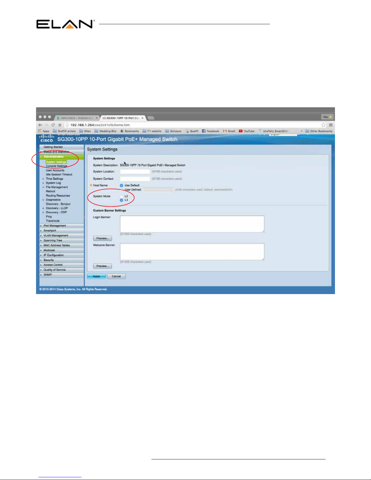
The rst setting you MUST update is to turn the network switch to Layer 3 mode. This must be completed before all other setting
changes are made as this will default the factory settings when Layer 3 is activated.
Under ‘Administration’ menu
Select ‘System settings’
Tick ‘L3’ (Layer 3) checkbox adjacent to System mode
Activating Layer 3 mode
Click ‘Apply’ to update the setting. A warning message will appear to make sure that you mean to factory reset the switch. Click
‘OK’ to proceed.
Please note: The switch will reboot which will take 3-4 minutes. After this is complete you will have to re-enter new password
details
Page 6

Cisco SG300 SETUP GUIDE
06
www.elanhomesystems.com
To enable Jumbo Frame,
Under ‘Port Management’ menu
Select ‘Port settings’
Tick ‘ENABLED’ checkbox adjacent to Jmubo Frames
tick ‘Jumbo Frame’ checkbox under Port Settings
Jumbo Frame
Click ‘Apply’ to update the setting
Page 7

Cisco SG300 SETUP GUIDE
07
contact techsupport@elanhomesystems.com
To enable IGMP snooping, there are several steps required to enable this feature:-
• Bridge Video Over IP Filter Status
• IGMP Snooping Status
• IGMP Querier Status
• MRouter Ports Auto Learn
• Immediate Leave
• IGMP Querier Election
The following pages explain how to update the above settings.
IGMP Snooping
Under ‘Video Over IP’ menu
Select ‘Properties’
Tick ‘Enabled’ checkbox adjacent to ‘Bridge Video Over IP Filter Status’
IGMP Snooping - Bridge Video Over IP Filter Status
Conrm other settings match those as shown in the above image
Click ‘APPLY’ to update the setting
Page 8

Cisco SG300 SETUP GUIDE
08
www.elanhomesystems.com
Under ‘Video Over IP’ menu
Select ‘IPv4 Video Over IP Conguration’
Select ‘IGMP Snooping’
Tick ‘Enabled’ checkbox adjacent to IGMP Snooping Status
Tick ‘Enabled’ checkbox adjacent to IGMP Query Status
IGMP Snooping - IGMP Snooping Status
Conrm other settings match those as shown in the above image
Click ‘APPLY’ to update the setting
Page 9

Cisco SG300 SETUP GUIDE
09
contact techsupport@elanhomesystems.com
Under ‘Video Over IP’ menu
Select ‘IPv4 Video Over IP Conguration’
Select ‘IGMP Snooping’
Select Line 1 in the IGMP Snooping table and click the ‘EDIT’ button
IGMP Snooping - IGMP Query Status, Mrouter ports auto
learn, Immediate leave & IGMP querier election
Tick ‘Enabled’ checkbox adjacent to IGMP Snooping Status
Tick ‘Enabled’ checkbox adjacent to Mrouter ports auto learn
Tick ‘Enabled’ checkbox adjacent to immediate leave
Tick ‘Enabled’ checkbox adjacent to IGMP querier status
Tick ‘Enabled’ checkbox adjacent to IGMP querier election
Conrm other settings match those as shown in the above image
Click ‘APPLY’ to update the setting
the following pop-up window will appear
Page 10

Cisco SG300 SETUP GUIDE
10
www.elanhomesystems.com
Not all Cisco SG300 switches support POE. Those network switches that do support POE come with this as factory default to
‘ON’. If you are unsure of the port setting please follow the below instructions.
Under ‘Port management’ menu
Select ‘POE’
Select ‘settings’
The following table shows the settings for each RJ45 LAN port on the network switch. POE administrative Status should be set to
‘Enabled’ meaning the POE feature is active. Default settings are for POE to be active (Enabled) so changes shoudl not be required.
If status is ‘Disabled please follow below instructions.
Turning On/O POE
To update the port settings click ‘EDIT’ which will open the following window:
Tick ‘Enabled’ checkbox for each interface (switch LAN connection) you wish POE to be active.
Click ‘APPLY’ to update the setting
Page 11

Cisco SG300 SETUP GUIDE
11
contact techsupport@elanhomesystems.com
All settings that have been previously updated will not be nalised until the conguration is saved and the switch is rebooted. To
save the conguration:
Under ‘Administration menu
Select ‘File Management’
Select ‘Copy/Save Conguration’
Apply and Save settings
Click ‘APPLY’ to save the settings
Then you must reboot the switch for settings to be applied
To reboot the switch:
Under ‘Administration menu
Select ‘File Management’
Select ‘Reboot’
Click ‘Reboot’
Note: The switch will take several minutes to reboot but will then be ready to use with the ELAN Video Over IP HDMI
products
Page 12

Cisco SG300 SETUP GUIDE
12
www.elanhomesystems.com
1) Connect your computer to your network switch using Ethernet cable
2) In the Windows toolbar navigate to ‘CONTROL PANEL’
3) Select ‘NETWORK AND INTERNET’
Changing your computer IP address to communicate with
the Cisco network switch
5) Select ‘NETWORK AND SHARING CENTER’
6) Under ‘View your Active Networks’ you can see connection types available.
The example below shows both LAN (local area connection) and Wireless.
Select ‘Local Area Connection’ as this is the method of communication you are using with the switch.
Page 13

Cisco SG300 SETUP GUIDE
13
contact techsupport@elanhomesystems.com
7) In the next window select ‘PROPERTIES’
8) A. In the ‘NETWORKING’ window highlight/select ‘INTERNET PROTOCOL VERSION 4 (TCP/IPv4)
B. Select ‘PROPERTIES’
Page 14

Cisco SG300 SETUP GUIDE
14
www.elanhomesystems.com
9) A. Under the ‘General’ tab select ‘USE THE FOLLOWING IP ADDRESS’
B. Enter the following FIXED IP network details
10) Click ‘OK’ and exit the network setup
11) Enter the default Cisco IP address in your web browser and check that you can connect to the unit.
Page 15

www.elanhomesystems.com
 Loading...