

Page 1
Cisco TelePresence SX20 Quick Set Administrator Guide
Contents
Introduction
Web interface
System settings
Setting passwords
Appendices
Software version TC6.0
JANUARY 2013
Administrator guide
for Cisco TelePresence SX20 Quick Set
D14908.02 SX20 Administrator Guide TC6.0, JANUARY 2013. www.cisco.com — Copyright © 2012-2013 Cisco Systems, Inc. All rights reserved.
1
Page 2

Cisco TelePresence SX20 Quick Set Administrator Guide
Contents
Introduction
Web interface
System settings
Setting passwords
Appendices
Contents
Thank you for choosing Cisco!
Your Cisco product has been designed to give you many
years of safe, reliable operation.
This part of the product documentation is aimed at
administrators working with the setup of the MX200.
Our main objective with this Administrator guide is to address
your goals and needs. Please let us know how well we
succeeded!
May we recommend that you visit the Cisco web site
regularly for updated versions of this guide.
The user documentation can be found on
► http://www.cisco.com/go/telepresence/docs
How to use this guide
The top menu bar and the entries in the Table of contents are
all hyperlinks. You can click on them to go to the topic.
Table of contents
Introduction ............................................................................ 4
User documentation ................................................................ 5
Software .................................................................................. 5
What’s new in this version ....................................................... 6
Cisco TelePresence SX20 Quick Set at a glance .................... 9
Web interface ...................................................................... 10
Starting the web interface ..................................................... 11
Changing the system password ............................................ 12
The interactive menu ............................................................. 13
System information ................................................................ 14
Placing a call .......................................................................... 15
Sharing content ...................................................................... 16
Controlling and monitoring a call ........................................... 17
Controlling the camera .......................................................... 18
Local layout control ................................................................ 19
Capturing snapshots .............................................................. 20
Managing the local phone book............................................. 21
Local phone book folders ...................................................... 22
System configuration .............................................................23
Changing system settings ..................................................... 24
Setting the Administrator Settings menu password .............. 25
System status ........................................................................26
Choosing a wallpaper ............................................................ 27
Choosing a ringtone ...............................................................28
Peripherals overview ............................................................. 29
User administration ................................................................ 30
Adding a sign in banner ......................................................... 33
Application programming interface........................................ 34
Managing the video system’s certificates ............................. 35
Managing the list of trusted certificate authorities ................ 36
Adding audit certificates ........................................................ 37
Setting strong security mode ................................................ 38
Deleting trust lists (CUCM only) ............................................. 39
Troubleshooting ..................................................................... 40
Downloading log files ............................................................. 41
Upgrading the system software............................................. 42
Backup and restore ................................................................ 43
Factory reset .......................................................................... 44
Restarting the system ............................................................ 45
System settings ................................................................... 46
Overview of the system settings ........................................... 47
Audio settings ........................................................................ 50
Cameras settings ................................................................... 51
Conference settings .............................................................. 54
FacilityService settings .......................................................... 59
H323 settings ......................................................................... 60
Network settings .................................................................... 63
NetworkServices settings ...................................................... 69
Phonebook settings ............................................................... 74
Provisioning settings .............................................................. 75
RTP settings ........................................................................... 77
Security settings .................................................................... 78
SerialPort settings.................................................................. 80
SIP settings ............................................................................ 81
Standby settings .................................................................... 83
SystemUnit settings ............................................................... 84
Time settings ......................................................................... 86
UserInterface settings............................................................ 87
Video settings ........................................................................ 88
Experimental settings ............................................................ 99
Setting passwords ............................................................. 100
Setting the system password .............................................. 101
Setting the menu password ................................................. 102
Setting a root password ....................................................... 103
D14908.02 SX20 Administrator Guide TC6.0, JANUARY 2013. www.cisco.com — Copyright © 2012-2013 Cisco Systems, Inc. All rights reserved.
2
Page 3

Cisco TelePresence SX20 Quick Set Administrator Guide
Contents
Introduction
Web interface
System settings
Setting passwords
Appendices
Contents
Appendices ........................................................................ 104
Power button and LED indicator .......................................... 105
Connecting the Cisco TelePresence Touch 8” controller .... 106
Rear panel ............................................................................ 107
Pin-out schemes ................................................................. 10 8
About monitors .................................................................... 109
Optimal definition profiles .....................................................110
ClearPath — Packet loss resilience .......................................111
Requirement for speaker systems connected to a
Cisco TelePresence C Series codec ....................................112
Factory resetting ...................................................................113
Factory resetting the Touch 8” controller .............................114
Technical specification for SX20 Quick Set ..........................115
Supported RFCs ...................................................................117
User documentation on the Cisco web site ..........................118
Intellectual property rights ....................................................119
Cisco contacts ....................................................................119
D14908.02 SX20 Administrator Guide TC6.0, JANUARY 2013. www.cisco.com — Copyright © 2012-2013 Cisco Systems, Inc. All rights reserved.
3
Page 4

Cisco TelePresence SX20 Quick Set Administrator Guide
Contents
Introduction
Web interface
System settings
Setting passwords
Appendices
Introduction
Chapter 1
Introduction
D14908.02 SX20 Administrator Guide TC6.0, JANUARY 2013. www.cisco.com — Copyright © 2012-2013 Cisco Systems, Inc. All rights reserved.
4
Page 5

Cisco TelePresence SX20 Quick Set Administrator Guide
Contents
Introduction
Web interface
System settings
Setting passwords
Appendices
Introduction
This document provides you with the information required to
administrate your product at an advanced level.
How to install the product and the initial configurations
required are described in the Installation guide and Getting
started guide, respectively.
Products covered in this guide
• Cisco TelePresence SX20 Quick Set
User documentation
The user documentation for the Cisco TelePresence systems
running the TC software includes several guides suitable for
various user groups.
• Installation guide:
How to install the product
• Getting started guide:
Initial configurations required to get the system up and
running
• Administering TC Endpoints on CUCM:
Tasks to perform to start using the product with the Cisco
Unified Communications Manager (CUCM)
• Administrator guide (this guide):
Information required to administer your product
• Quick reference guides:
How to use the product (remote control and Touch
controller)
• User guides:
How to use the product (remote control and Touch
controller)
• Camera user guide:
User guide for the PrecisionHD cameras
• API reference guide:
How to use the Application Programmer Interface (API),
and reference guide for the command line commands
• Knowledge base articles
• Video conferencing room primer:
General guidelines for room design and best practice
• Video conference room acoustics guidelines:
Things to do to improve the perceived audio quality
• Software release notes
• Regulatory compliance and safety information guide
• Legal & license information
Downloading the user documentation
We recommend you visit the Cisco web site regularly for
updated versions of the user documentation. Go to:
► http://www.cisco.com/go/telepresence/docs
Guidelines how to find the documentation
on the Cisco web site are included in the
► User documentation on the Cisco web site appendix.
Software
You can download the software for your product from the
Cisco web site, go to:
► http://www.cisco.com/cisco/software/navigator.html
We recommend reading the Software Release Notes (TC6),
go to:
► http://www.cisco.com/en/US/products/ps11424/tsd_
products_support_series_home.html
D14908.02 SX20 Administrator Guide TC6.0, JANUARY 2013. www.cisco.com — Copyright © 2012-2013 Cisco Systems, Inc. All rights reserved.
5
Page 6

Cisco TelePresence SX20 Quick Set Administrator Guide
Contents
Introduction
Web interface
System settings
Setting passwords
Appendices
Introduction
What’s new in this version
This section provides an overview of the new and changed
system settings and new features in the TC6.0 software
version.
Software release notes
For a complete overview of the news and changes, we
recommend reading the Software Release Notes (TC6). Go
to:
► http://www.cisco.com/en/US/products/ps11424/tsd_
products_support_series_home.html
Software download
For software download go to:
► http://www.cisco.com/cisco/software/navigator.html
New features and improvements
Administrator password not set warning on OSD
If the administrator password is not set, there is an on screen
warning in the lower right corner indicating this. The warning
disappears when the password is set.
Improved video layout
• Improved local layout control when using the
Touch controller
You can easily choose between the layout options using
the Touch controller. Each option is illustrated by an icon
reflecting the actual layout.
You can choose between the predefined layout options
as well as any custom layouts that have been created for
this TelePresence system (for example created with the
TC Console application).
• Picture-in-Picture support
There is support for showing Picture-in-Picture (PIP), for
example showing a full screen presentation with both
remote video and self view as PIP.
The PIPs can be moved to predefined drop zones,
typically upper right, upper left, lower right etc. When
using a Touch controller you can see the drop zones as
you start moving the PIP.
• Changing the video layout on remote sites
When you are hosting a MultiSite conference, you can
change the video layout sent to remote sites.
• Lock Speaker function in MultiSite conferences
When you are hosting a MultiSite conference, you can
use Lock speaker to keep the large picture for the same
participant for the entirety of the call (no audio-driven
switching between participants).
• Full screen self view
Full screen self view while in call is supported on dual
monitor systems.
Support for Cisco TelePresence ISDN Link
You can pair a TelePresence system with a Cisco
TelePresence ISDN Link. As from software versions TC6.0
and IL1.1 automatic pairing mode is supported.
When making a call via ISDN Link, choose H320 (ISDN) as the
call protocol.
Secure communication in a CUCM environment
As from version TC5 endpoints running TC software can
register to a Cisco Unified Communications Manager (CUCM)
version 8.6.2 or newer. In TC6.0 this feature is extended to
also include secure (encrypted) connections. The encryption
indicator is shown on the screen during a call.
This feature requires that security mode is installed and
configured on CUCM. Read the Administering TC Endpoints
on CUCM 9.0 guide to find how to set up this feature.
Support for SIP URI dialing when registered to CUCM
As from Cisco Unified Communications Manager (CUCM)
version 9.0, endpoints registered to CUCM support URI
dialing. A URI is an alias for a directory number (DN). A call
to the URI behaves as if the call was made directly to the
directory number.
URI example: conference_room@company.com. The user
name (left side) is case sensitive in CUCM 9.0, while the
domain (right side) is not.
D14908.02 SX20 Administrator Guide TC6.0, JANUARY 2013. www.cisco.com — Copyright © 2012-2013 Cisco Systems, Inc. All rights reserved.
6
Page 7

Cisco TelePresence SX20 Quick Set Administrator Guide
Contents
Introduction
Web interface
System settings
Setting passwords
Appendices
Introduction
Dynamic bandwidth distribution in MultiSite conferences
You can choose a total bandwidth for your MultiSite
conference. The bit rate is divided equally among all the
active calls at any time. This means that the individual calls
will be up-speeded or down-speeded as appropriate when
someone leaves or enters the MultiSite conference, and
when a call is put on-hold or resumed.
Support for encrypted Cisco TelePresence Multipoint
Switch (CTMS) calls
Video systems running software TC5.0 or later are able
to initiate or join non-encrypted multiparty conferences
controlled by CTMS version 1.8 or later. Encrypted
conferences are supported as from software versions TC6.0
and CTMS 1.9.1.
The TelePresence system must have a secure registration to
VCS or CUCM to allow encrypted calls.
Troubleshooting and diagnostics
A new troubleshooting feature is introduced. The
TelePresence system runs a set of tests to detect possible
problems and provides links on the web interface to resolve
the issues.
The Mediatrace diagnostics tool
Mediatrace is a diagnostics tool that discovers the routers
and switches (layer 2 and 3 devices) along the path of an IP
flow. It collects critical information hop by hop on specific
media streams as they traverse the network. Mediatrace
should be enabled on each network node you want to collect
information from. Because the path of video data packets
from the endpoints is traced, troubleshooting is facilitated and
network performance can be optimized.
New and improved web interface features
• Local phone book management, for example creating
a folder structure, and adding, modifying or deleting
contacts.
Note that the web interface’s local phone book mirrors
the Favorites list on the Touch controller and the My
contacts folder in the OSD phone book.
• Improved interface for uploading certificates and
certificate authority lists to the TelePresence system.
• Display of diagnostics information, including links how to
resolve pending issues.
• Information about connected peripherals, e.g. Touch
controller, cameras and displays.
• Configuration interface for the Cisco TelePresence ISDN
Link gateway (only applicable if an ISDN Link gateway is
connected to the TelePresence system).
New languages supported on Touch
• Czech
• Dutch
• Hungarian
• Italian
• Korean
• Polish
• Portuguese Brazilian
• Traditional Chinese
• Tur k i s h
D14908.02 SX20 Administrator Guide TC6.0, JANUARY 2013. www.cisco.com — Copyright © 2012-2013 Cisco Systems, Inc. All rights reserved.
7
Page 8

Cisco TelePresence SX20 Quick Set Administrator Guide
Contents
Introduction
Web interface
System settings
Setting passwords
Appendices
Introduction
System configuration changes
New settings
Audio Input HDMI Mode
Conference DoNotDisturb DefaultTimeout
Conference MaxTotalTransmitCallRate
Conference MaxTotalReceiveCallRate
Conference Presentation RelayQuality
Conference Presentation OnPlacedOnHold
Network QoS Diffserv ICMPv6
Network QoS Diffserv NTP
NetworkServices CTMS Mode
NetworkServices CTMS Encryption
NetworkServices XMLAPI Mode
SIP ListenPort
Video SelfviewDefault Mode
Video SelfviewDefault FullscreenMode
Video SelfviewDefault PIPPosition
Video SelfviewDefault OnMonitorRole
Video PIP ActiveSpeaker DefaultValue Position
Video PIP Presentation DefaultValue Position
Video Input Source[1..n] PresentationSelection
Video Input HDMI[1..n] RGBQuantizationRange
Video Input DVI[x, y] RGBQuantizationRange
Video Output HDMI[x, y] RGBQuantizationRange
Video OSD MenuStartupMode
Video OSD VirtualKeyboard
Video OSD EncryptionIndicator
Video OSD MissedCallsNotification
Settings that are removed
Network DNS Server[4, 5] Address
Settings that are modified
Cameras PowerLine Frequency
OLD: <Auto/50Hz/60Hz>
NEW: <50Hz/60Hz>
Conference DefaultCall Protocol
OLD: <H323/Sip>
NEW: <H323/Sip/H320>
Network IPv6 Assignment
OLD: <Static/Autoconf>
NEW: <Static/DHCPv6/Autoconf>
SystemUnit ContactInfo Type
OLD: <Auto/None/IPv4/IPv6/H323Id/E164Alias/SipUri/
SystemName>
NEW: <Auto/None/IPv4/IPv6/H323Id/E164Alias/
H320Number/SipUri/SystemName/DisplayName>
UserInterface TouchPanel DefaultPanel
OLD: <ContactList/MeetingList>
NEW: <ContactList/MeetingList/Dialpad>
Video SelfviewPosition
OLD: <UpperLeft/UpperRight/CenterRight/LowerLeft/
LowerRight>
NEW: <UpperLeft/UpperCenter/UpperRight/CenterLeft/
CenterRight/LowerLeft/LowerRight>
Video Layout LocalLayoutFamily
OLD: <Auto/FullScreen/Equal/PresentationSmallSpeaker/
PresentationLargeSpeaker>
NEW: <Auto/FullScreen/Equal/PresentationSmallSpeaker/
PresentationLargeSpeaker/Prominent/Overlay/Single>
Video Layout RemoteLayoutFamily
OLD: <Auto/FullScreen/Equal/PresentationSmallSpeaker/
PresentationLargeSpeaker>
NEW: <Auto/FullScreen/Equal/PresentationSmallSpeaker/
PresentationLargeSpeaker/Prominent/Overlay/Single>
Video Input Source[1..n] OptimalDefinition Threshold60fps
OLD: <512_288/ 768_448/1024 _ 5 76/128 0 _72 0/Nev e r >
NEW: <512 _ 2 8 8/76 8 _ 4 4 8/10 24_576/1280_ 720 /
1920_1080/Never>
Video Wallpaper
OLD: <None/Growing/Summersky/Custom/Wallpaper01/
Wallpaper02/Wallpaper03/Wallpaper04/Wallpaper05/
Wallpaper06/Wallpaper07/Wallpaper08/Wallpaper09/
Wallpaper10/Wallpaper11/Wallpaper12>
NEW: <None/Growing/Summersky/Custom/Waves>
D14908.02 SX20 Administrator Guide TC6.0, JANUARY 2013. www.cisco.com — Copyright © 2012-2013 Cisco Systems, Inc. All rights reserved.
8
Page 9
Cisco TelePresence SX20 Quick Set Administrator Guide
Contents
Introduction
Web interface
System settings
Setting passwords
Appendices
Introduction
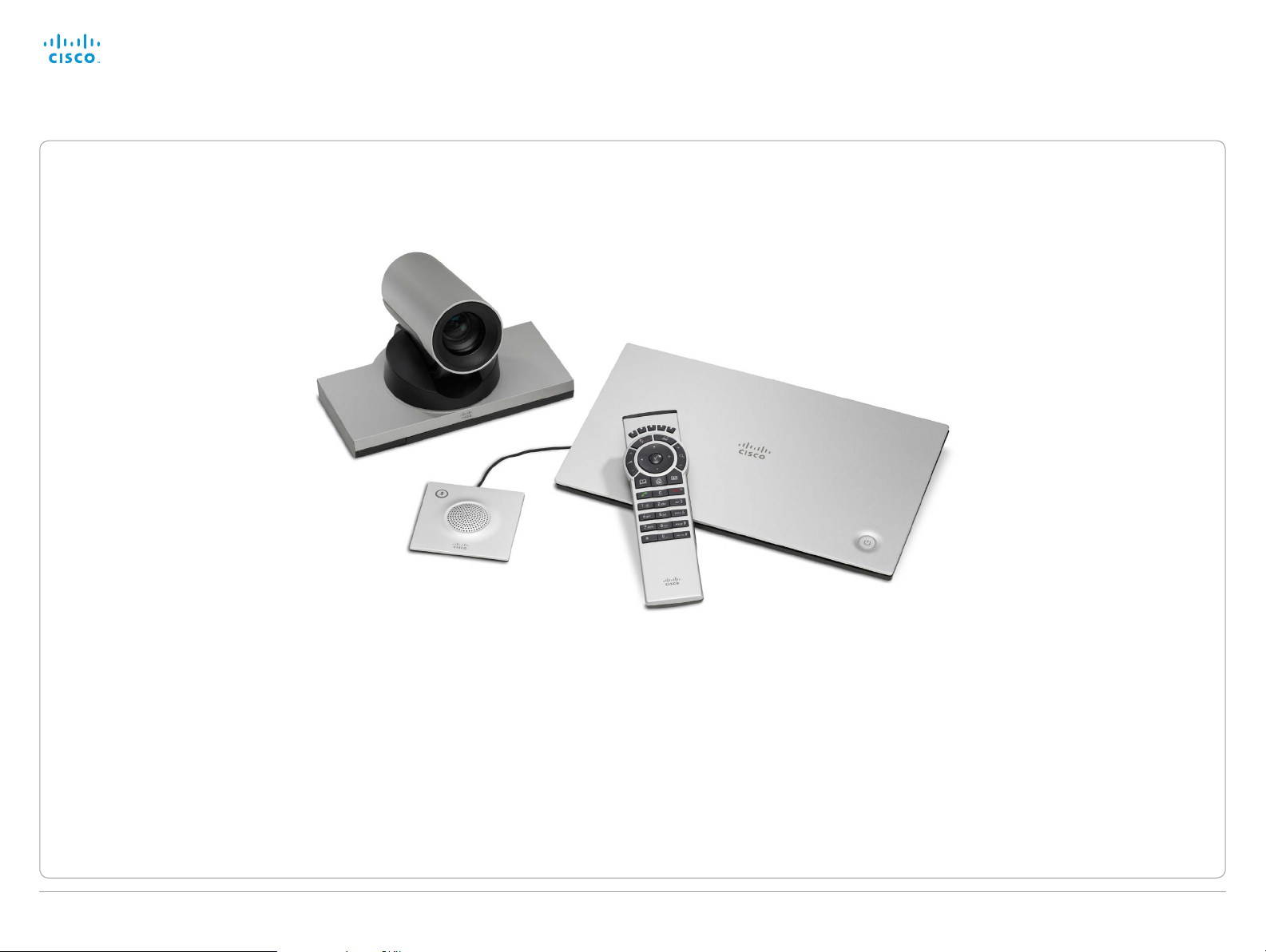
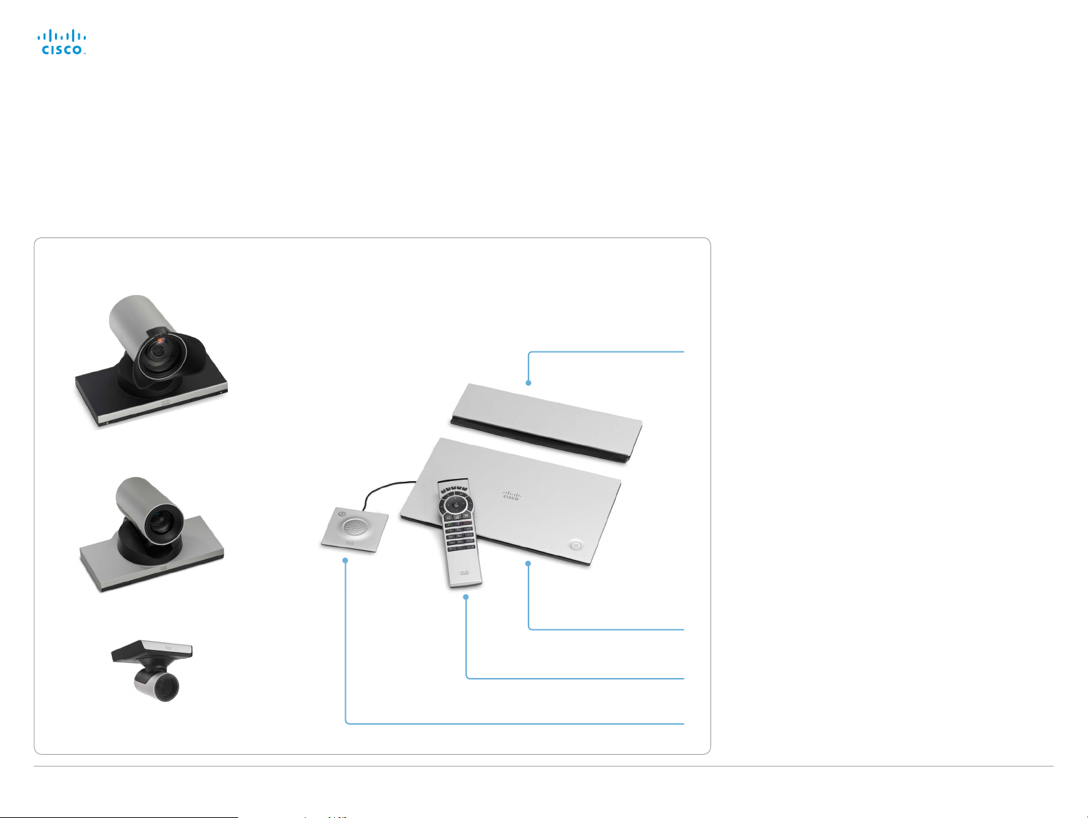
Cisco TelePresence SX20 Quick Set at a glance
The Cisco TelePresence® SX20 Quick Set can transform
a standard flat panel display into a powerful telepresence
system.
Precision HD camera options
12x z o o m
Whether you are just getting started with video
communications or implementing a large-scale deployment,
the SX20 Quick Set delivers high quality performance.
Wall mounting kit
(optional)
Features and benefits
• The system is easily installed. Also mounts easily on the
wall (optional wall mount kit).
• The system is self-configuring with Cisco Unified
Communications Manager (UCM) or Cisco WebEx
TelePresence provisioning. All you need is to authenticate
your endpoint to the network.
• Three PrecisionHD camera options with pan, tilt, and
zoom helps ensure optimal framing and video clarity.
• Dedicated camera presets provide flexibility and easy
viewing for any meeting scenario.
• Operation using remote controll and on-screen menu
(default); or 8-inch Touch interface (optional).
• Simple one-button-to-push calling integrates with
common calendar programs.
• Video resolution and frame rate up to 1080p60.
• You can connect and share your PC content at 1080p15
resolution and frame rate.
• Dual display option available.
• The systems support H.323 and Session Initiation
Protocol (SIP) with bandwidth up to 6 Mbps point-topoint.
• The system is compatible with standards-based video
systems without loss of features.
• Capabilities for multipoint conferences using the Cisco
TelePresence Multiway™ technology, or the built in 4 way
Cisco TelePresence MultiSite feature (no external bridge).
4x zoom
SX20 Codec
Remote control
1 microphone
(+ 1 optional) 2.5x zoom
D14908.02 SX20 Administrator Guide TC6.0, JANUARY 2013. www.cisco.com — Copyright © 2012-2013 Cisco Systems, Inc. All rights reserved.
9
Page 10

Cisco TelePresence SX20 Quick Set Administrator Guide
Contents
Introduction
Web interface
System settings
Setting passwords
Appendices
Web interface
Chapter 2
Web interface
D14908.02 SX20 Administrator Guide TC6.0, JANUARY 2013. www.cisco.com — Copyright © 2012-2013 Cisco Systems, Inc. All rights reserved.
10
Page 11
Cisco TelePresence SX20 Quick Set Administrator Guide
Contents
Introduction
Web interface
System settings
Setting passwords
Appendices
Web interface
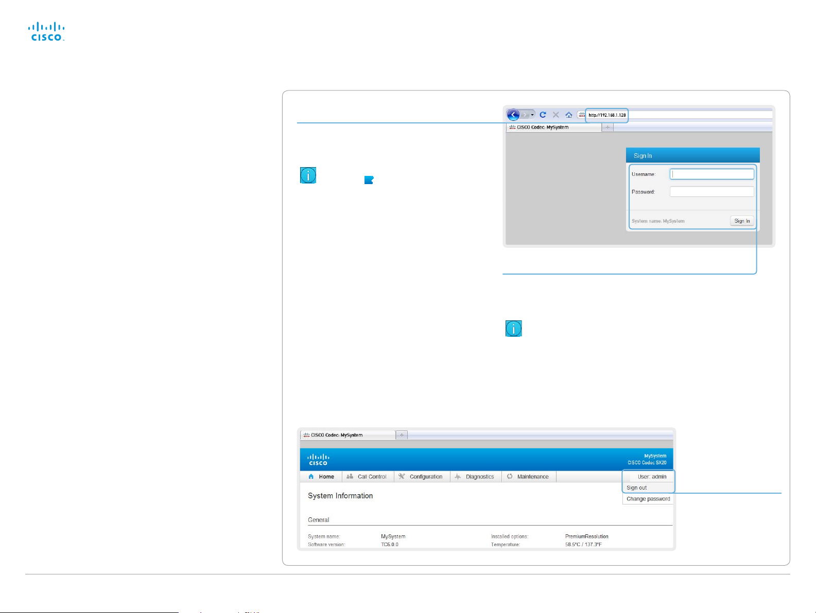
Starting the web interface
The web interface provides full configuration access to your
video conference system.
You can connect from a computer and administer the system
remotely.
In this chapter you will find information how to use the web
interface for system configuration and maintenance.
Browsers:
• The latest releases of Internet Explorer, Mozilla Firefox,
Opera, Chrome or Safari are recommended
• Major TC6.0 functionality works with Internet Explorer 7
1. Connect to the video system
Open a web browser and enter the IP address of
the video system in the address bar.
To find the IP address (IPv4 orIPv6), tap
Settings (
or navigate to Home > Settings >
System information when using a remote
control and the on-screen menu.
) on a Touch controller;
2. Sign in
Enter the user name and password for your video
system and click Sign In.
The system is delivered with a default user
named admin with no password (i.e. leave the
Password field blank when signing in for the first
time).
We strongly recommend that you set a
password for the admin user, see the next page.
Signing out
Hover the mouse
over your user
name and choose
Sign out from the
drop-down list.
D14908.02 SX20 Administrator Guide TC6.0, JANUARY 2013. www.cisco.com — Copyright © 2012-2013 Cisco Systems, Inc. All rights reserved.
11
Page 12
Cisco TelePresence SX20 Quick Set Administrator Guide
Contents
Introduction
Web interface
System settings
Setting passwords
Appendices
Web interface
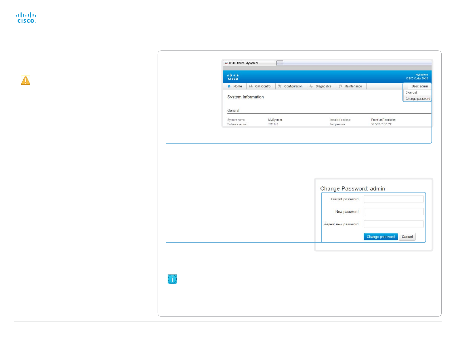
Changing the system password
We strongly recommend that you set a password
for any user with ADMIN rights, including the default
admin user, to restrict access to system configuration.
You can read more about password protection in the
► Setting passwords chapt er.
1. Open the Change Password dialog
Hover the mouse over your user name, and
choose Change password in the drop-down list.
2. Set the new password
Enter your current and new passwords as
requested, and click Change password for the
change to take effect.
If the password currently is not set, leave
the Current password field blank.
D14908.02 SX20 Administrator Guide TC6.0, JANUARY 2013. www.cisco.com — Copyright © 2012-2013 Cisco Systems, Inc. All rights reserved.
12
Page 13
Cisco TelePresence SX20 Quick Set Administrator Guide
Contents
Introduction
Web interface
System settings
Setting passwords
Appendices
Web interface
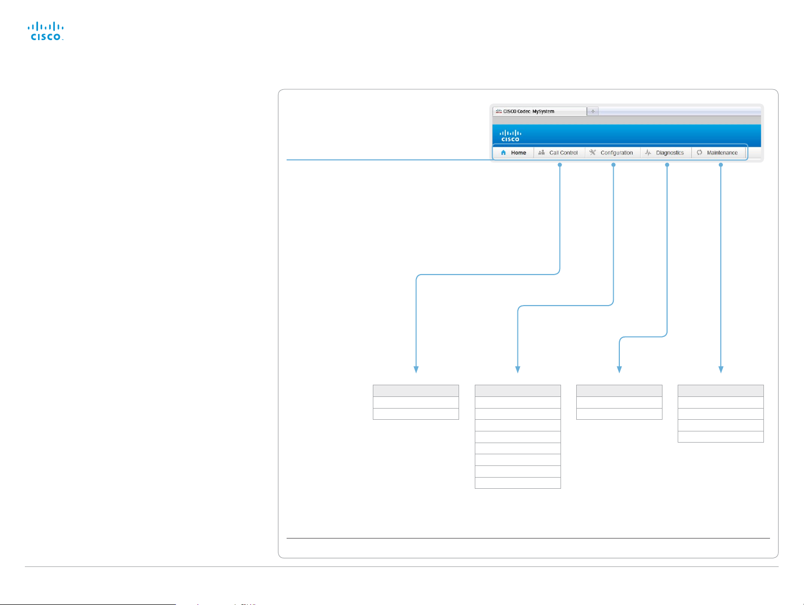
The interactive menu
The web interface provides access to tasks and
configurations. They are available from the main menu, which
appears near the top of the page when you have signed in.
When you hover the mouse over a main menu item, you can
navigate to its related sub-pages.
Main menu
Hover the mouse over a main menu item, the
titles of related sub-pages drops down.
Click a sub-page’s title to open it. Only pages
that the user has access rights for can be
opened; the others are dimmed.
*
Click Home on the main menu to return to the
System Information page.
Sub-pages
*
You can read more about user administration, user roles and access rights in the ► User administration section.
D14908.02 SX20 Administrator Guide TC6.0, JANUARY 2013. www.cisco.com — Copyright © 2012-2013 Cisco Systems, Inc. All rights reserved.
Call Control
Call Control
Local Phone Book
13
Configuration
System Configuration
System Status
Personalization
Peripherals
User Administration
Sign In Banner
API
Security
Diagnostics
Troubleshooting
Log Files
Maintenance
Software Upgrade
Backup and Restore
Factory Reset
Restart
Page 14
Cisco TelePresence SX20 Quick Set Administrator Guide
Contents
Introduction
Web interface
System settings
Setting passwords
Appendices
Web interface
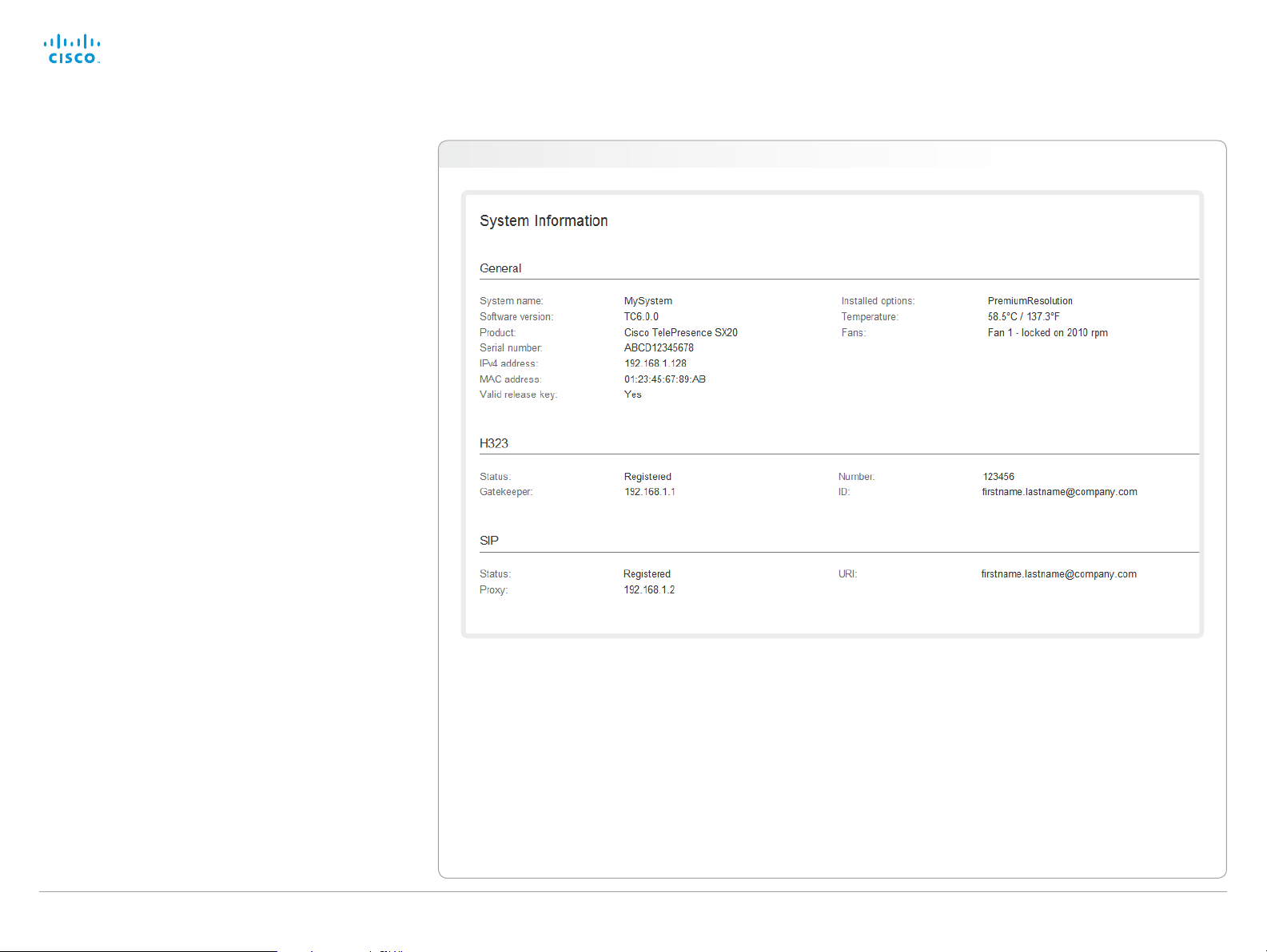
System information
The video system’s Home page shows an overview of the
basic set-up and status of the system.
This includes information like system name and product type,
which software version the system runs, its IPaddress, etc.
Also the registration status for the video networks (SIP and
H.323) is included, as well as the number/URI to use when
making a call to the system.
Home
D14908.02 SX20 Administrator Guide TC6.0, JANUARY 2013. www.cisco.com — Copyright © 2012-2013 Cisco Systems, Inc. All rights reserved.
14
Page 15
Cisco TelePresence SX20 Quick Set Administrator Guide
Contents
Introduction
Web interface
System settings
Setting passwords
Appendices
Web interface
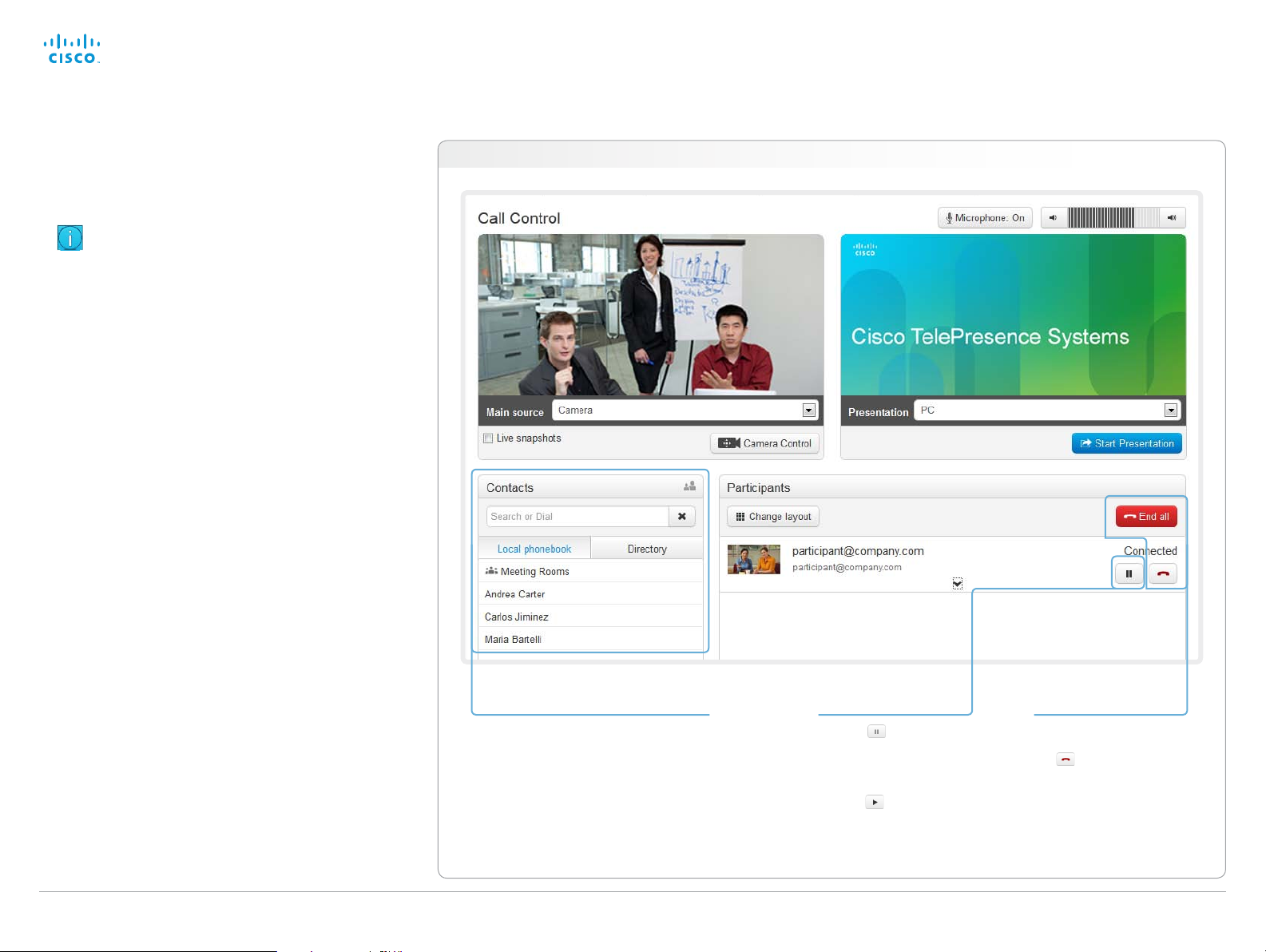
Placing a call
You can use the Call Control page of the web interface to
initiate a call.
Even if the web interface is used to initiate the call
it is the video system (display, microphones and
loudspeakers) that is used for the call; it is not the PC
running the web interface.
Calling
You can call someone either by choosing a contact name in
the Local phone book or Directory, or by typing a complete
URI or number in the Search and Dial field. Then click Call in
the associated contact card.
Searching the contact lists
Enter one or more characters in the Search or Dial field.
Matching entries from both the Local phone book and the
Directory will be listed as you type.
Select the entry in the phone book or directory before you
click Call.
Calling more than one
A point-to-point video call (a call involving two parties only)
may be expanded to include more participants.
If your system supports the optional built-in MultiSite feature,
up to four participants, yourself included, can join the video
call. The call will then become a video conference.
One additional participant can join on audio-only.
Follow the same procedure to call the next conference
participant as you did when calling the first participant.
Navigate to: Call Control > Call Control
Calling someone
Click a contact name, either in the
Local phone book or in the Directory.
Then click Call in the contact card.
Alternatively, enter the complete URI
or number in the Search and Dial field.
Then click the Call button that appears
next to the URI or number.
Holding and resuming
Use the
to the participant’s name
to put him on hold.
To resume the call,
use the button
that appears for the
participant on hold.
button next
Ending a call
To disconnect just one
participant in a call, click
the
button for that
participant.
Click the End all button to
terminate the entire call.
D14908.02 SX20 Administrator Guide TC6.0, JANUARY 2013. www.cisco.com — Copyright © 2012-2013 Cisco Systems, Inc. All rights reserved.
15
Page 16
Cisco TelePresence SX20 Quick Set Administrator Guide
Contents
Introduction
Web interface
System settings
Setting passwords
Appendices
Web interface
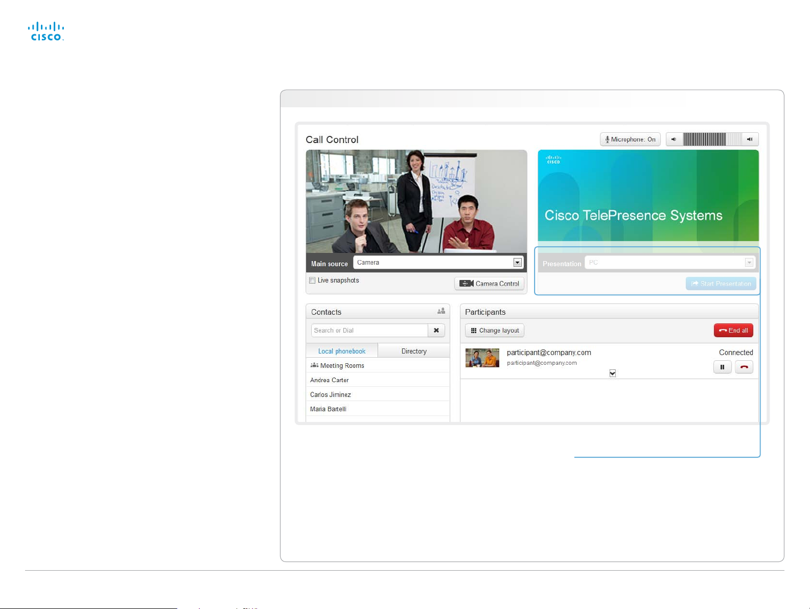
Sharing content
You can connect a presentation source to one of the external
inputs of your video system. Most often a PC is used as
presentation source, but other options may be available
depending on your system setup.
While in a call you can share content with the far end, that is
the other participant(s) in the call.
If you are not in a call, the content is shared locally on your
display.
Navigate to: Call Control > Call Control
Sharing content
1. Choose a Presentation source from the
drop-down list.
2. Click Start Presentation.
Stop content sharing:
Click the Stop Presentation button that becomes
visible while sharing.
D14908.02 SX20 Administrator Guide TC6.0, JANUARY 2013. www.cisco.com — Copyright © 2012-2013 Cisco Systems, Inc. All rights reserved.
16
Page 17
Cisco TelePresence SX20 Quick Set Administrator Guide
Contents
Introduction
Web interface
System settings
Setting passwords
Appendices
Web interface
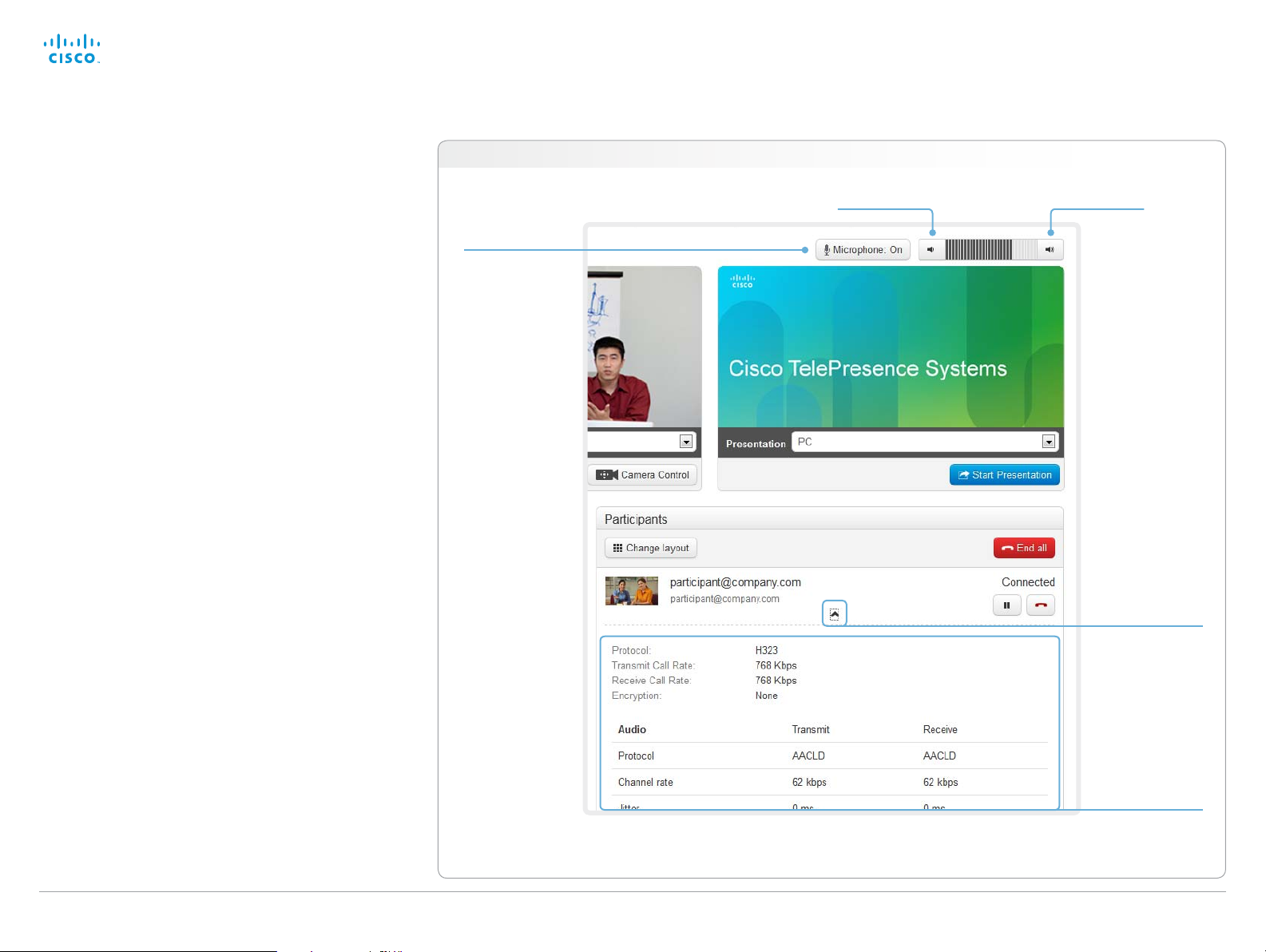
Controlling and monitoring a call
You can control and monitor several call features using the
Call Control page.
Navigate to: Call Control > Call Control
Microphone
mute
Click the button
to mute the
microphone.
Then the text
changes to
Microphone: Off.
Click again to
unmute.
Volume down
Volume up
Show/hide
call details
Click the arrow
to show details
about the call.
Click the arrow
again to hide the
information.
Call details
scroll your browser to
D14908.02 SX20 Administrator Guide TC6.0, JANUARY 2013. www.cisco.com — Copyright © 2012-2013 Cisco Systems, Inc. All rights reserved.
17
If necessary,
see the call details.
Page 18
Cisco TelePresence SX20 Quick Set Administrator Guide
Contents
Introduction
Web interface
System settings
Setting passwords
Appendices
Web interface
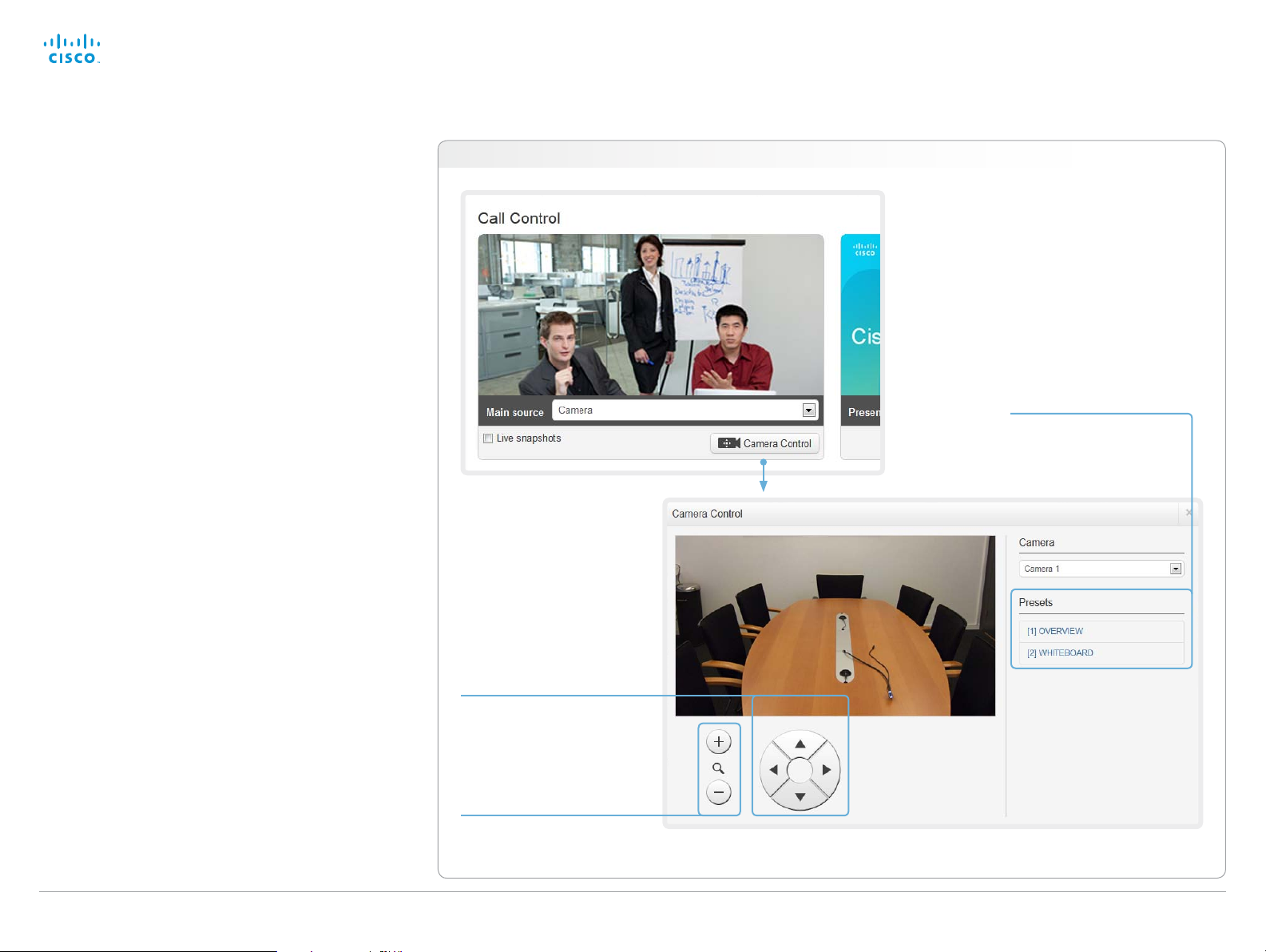
Controlling the camera
You can control the camera using the Call Control page.
Click the Camera Control button to open the window where
you can pan, tilt and zoom the camera, and apply camera
presets.
Navigate to: Call Control > Call Control
Camera presets
If a camera preset is
defined it is listed here.
Apply the preset by clicking
its name.
Pan and tilt
Use the left and right
arrows to pan the camera,
and the up and down
arrows to tilt it.
Zoom
Use + and - to zoom in and
out.
D14908.02 SX20 Administrator Guide TC6.0, JANUARY 2013. www.cisco.com — Copyright © 2012-2013 Cisco Systems, Inc. All rights reserved.
18
Page 19
Cisco TelePresence SX20 Quick Set Administrator Guide
Contents
Introduction
Web interface
System settings
Setting passwords
Appendices
Web interface
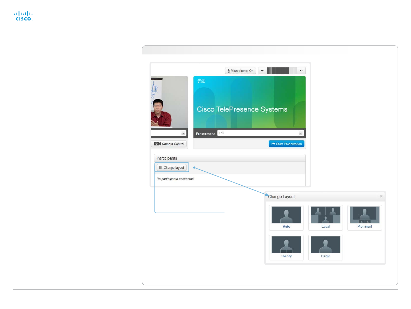
Local layout control
You can choose a local layout using the Call Control page.
The term layout is used to describe the various ways the
videos from the conference participants and a presentation
can appear on your screen. Different types of meetings will
require different layouts.
Navigate to: Call Control > Call Control
Change the layout
1. Click Change layout.
2. Choose your preferred layout
in the window that opens.
You may change the layout while
D14908.02 SX20 Administrator Guide TC6.0, JANUARY 2013. www.cisco.com — Copyright © 2012-2013 Cisco Systems, Inc. All rights reserved.
in a call.
19
Page 20
Cisco TelePresence SX20 Quick Set Administrator Guide
Contents
Introduction
Web interface
System settings
Setting passwords
Appendices
Web interface
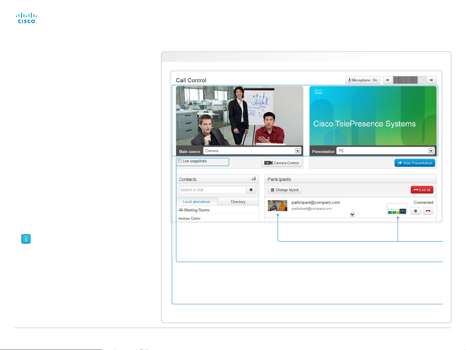
Capturing snapshots
The snapshot feature, which is disabled by default, allows
snapshots captured by your video system to be displayed
on the Call Control page. Captures from your video system’s
camera as well as from its presentation channel will be
displayed.
This feature might come in handy when administering the
video system from a remote location, e.g. to check the
camera view.
To use web snapshots you have to sign in with ADMIN
credentials.
Enabling the snapshot feature
The snapshot feature is disabled by default. The feature must
be enabled using the remote control and on screen menu.
• Go to the Advanced configuration menu, navigate to
Video > AllowWebSnapshots and choose On.
Far end snapshots while in a call
While in a call, snapshots of the remote participant’s main
camera and presentation channel (far end) will be captured
and displayed as shown in the illustration. The snapshots are
updated approximately every 20seconds.
Navigate to: Call Control > Call Control
Far end snapshots are captured even if web
snapshots are disallowed on the far end video
system. Web snapshots are prohibited only for
encrypted calls.
snapshots are captured by your video system (main
camera and presentation) approximately every two
D14908.02 SX20 Administrator Guide TC6.0, JANUARY 2013. www.cisco.com — Copyright © 2012-2013 Cisco Systems, Inc. All rights reserved.
20
While the Live snapshots box is checked,
Snapshots from your video system
Far end snapshots
Take live snapshots
seconds.
Page 21
Cisco TelePresence SX20 Quick Set Administrator Guide
Contents
Introduction
Web interface
System settings
Setting passwords
Appendices
Web interface
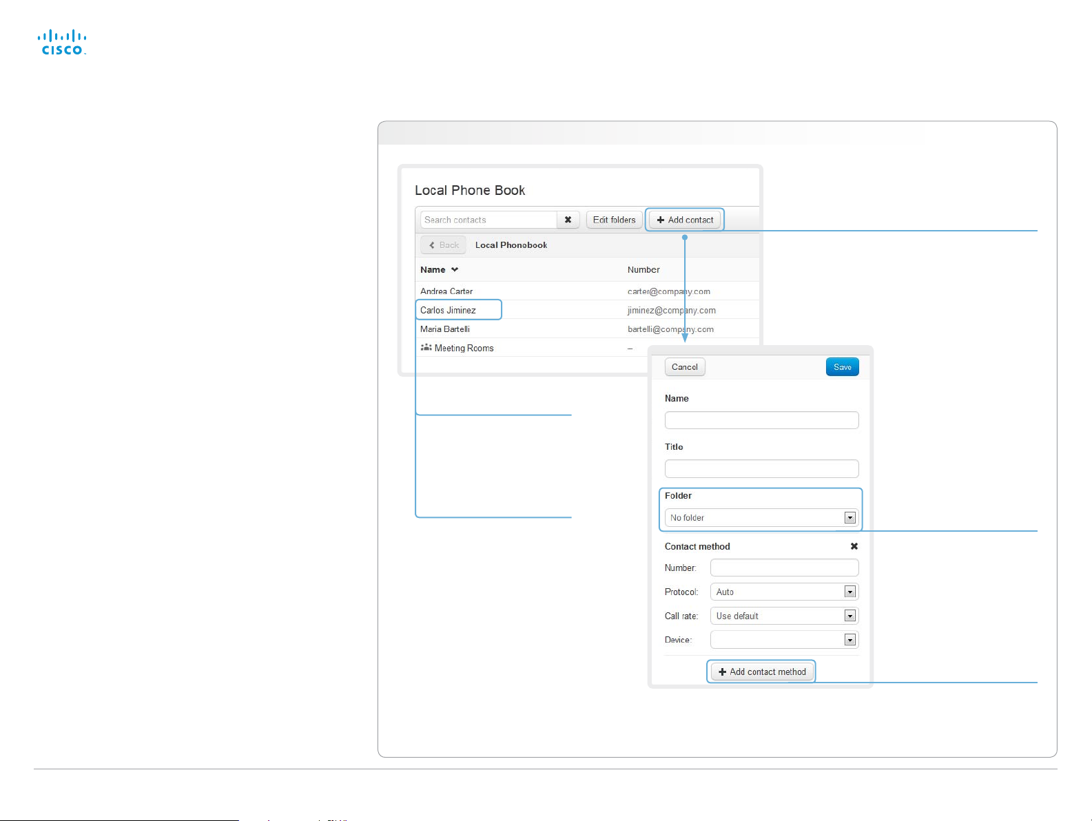
Managing the local phone book
The entries in the local phone book can be accessed from
the following interfaces:
• Touch controller: The Favorites list
• On-screen menu: The My contacts folder in the phone
book
• Web interface: The local phone book on the call control
page
Navigate to: Call Control > Local Phone Book
Editing contact details
Click a contacts name
followed by Edit. Change
the details in the form as
appropriate and click Save.
Deleting a contact
Click a contacts name
followed by Edit. Then click
Delete to remove the entry
from the local phone book.
Adding a contact
Click Add contact and fill in
the form that pops up. Then
click Save to store the contact
in the local phone book.
Storing a contact in a folder
Choose the appropriate folder
from the drop down list.
No folder means that the
contact will be stored at the
top level.
Adding a contact method
You can store more than one
contact method for each
contact, e.g. video, telephone
D14908.02 SX20 Administrator Guide TC6.0, JANUARY 2013. www.cisco.com — Copyright © 2012-2013 Cisco Systems, Inc. All rights reserved.
21
and mobile.
Page 22
Cisco TelePresence SX20 Quick Set Administrator Guide
Contents
Introduction
Web interface
System settings
Setting passwords
Appendices
Web interface
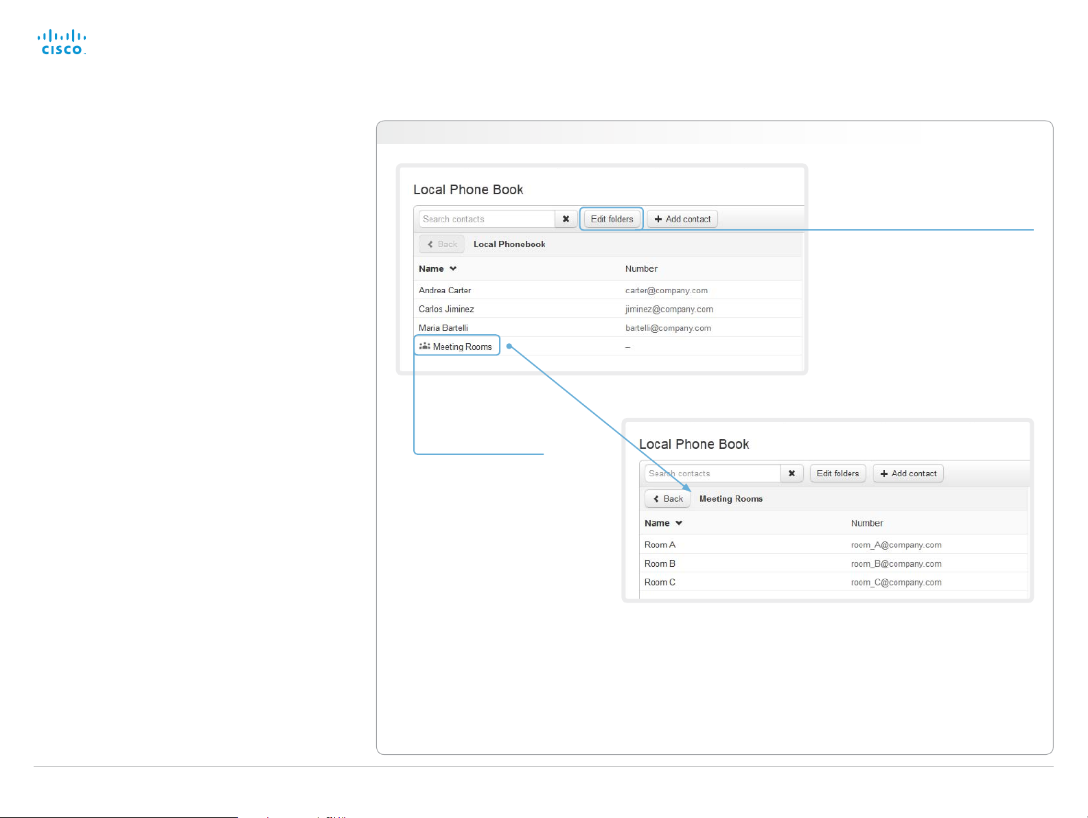
Local phone book folders
The entries in the local phone book can be hierarchically
organized in folders.
Navigate to: Call Control > Local Phone Book
Managing folders
i. Click Edit folders.
ii. Click Add folder and fill in its details
to create at new folder; or click the
name of an existing folder to view
and edit its details.
iii. Click Save folder to store the
details; or click Delete folder to
remove a folder and all its contacts
and sub-folders.
Opening a folder
Click the folder name
to open the folder and
show its list of contacts.
D14908.02 SX20 Administrator Guide TC6.0, JANUARY 2013. www.cisco.com — Copyright © 2012-2013 Cisco Systems, Inc. All rights reserved.
22
Page 23
Cisco TelePresence SX20 Quick Set Administrator Guide
Contents
Introduction
Web interface
System settings
Setting passwords
Appendices
Web interface
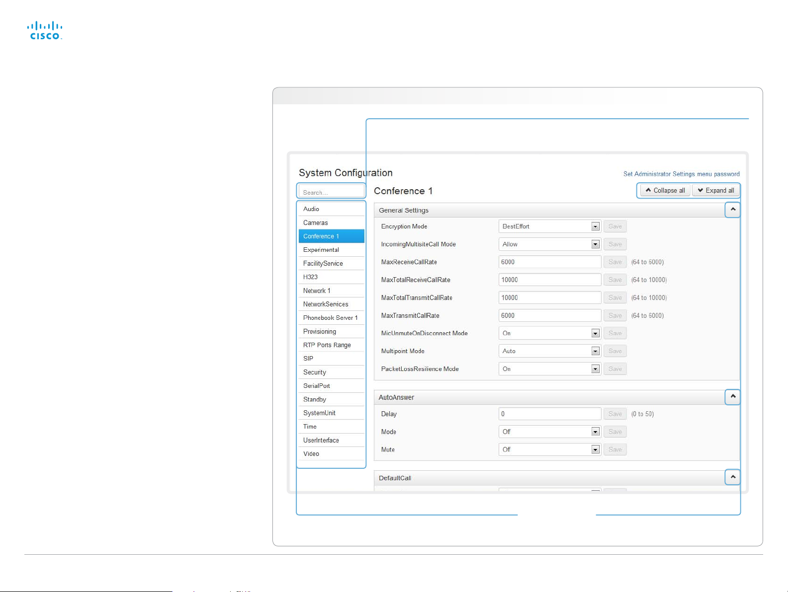
System configuration
The system settings are grouped in several categories. When
you choose a category in the left pane all related settings
appear to the right.
Each system setting is further described in the
► System settings chap ter.
Navigate to: Configuration > System Configuration
Searching for settings
Enter as many letters as needed in the search field.
All settings containing these letters will be highlighted.
Selecting a category
The system settings are structured in several categories.
Choose a category to display the related settings.
D14908.02 SX20 Administrator Guide TC6.0, JANUARY 2013. www.cisco.com — Copyright © 2012-2013 Cisco Systems, Inc. All rights reserved.
23
Expanding and collapsing lists
Use the buttons to expand and collapse
all or individual lists.
Page 24
Cisco TelePresence SX20 Quick Set Administrator Guide
Contents
Introduction
Web interface
System settings
Setting passwords
Appendices
Web interface
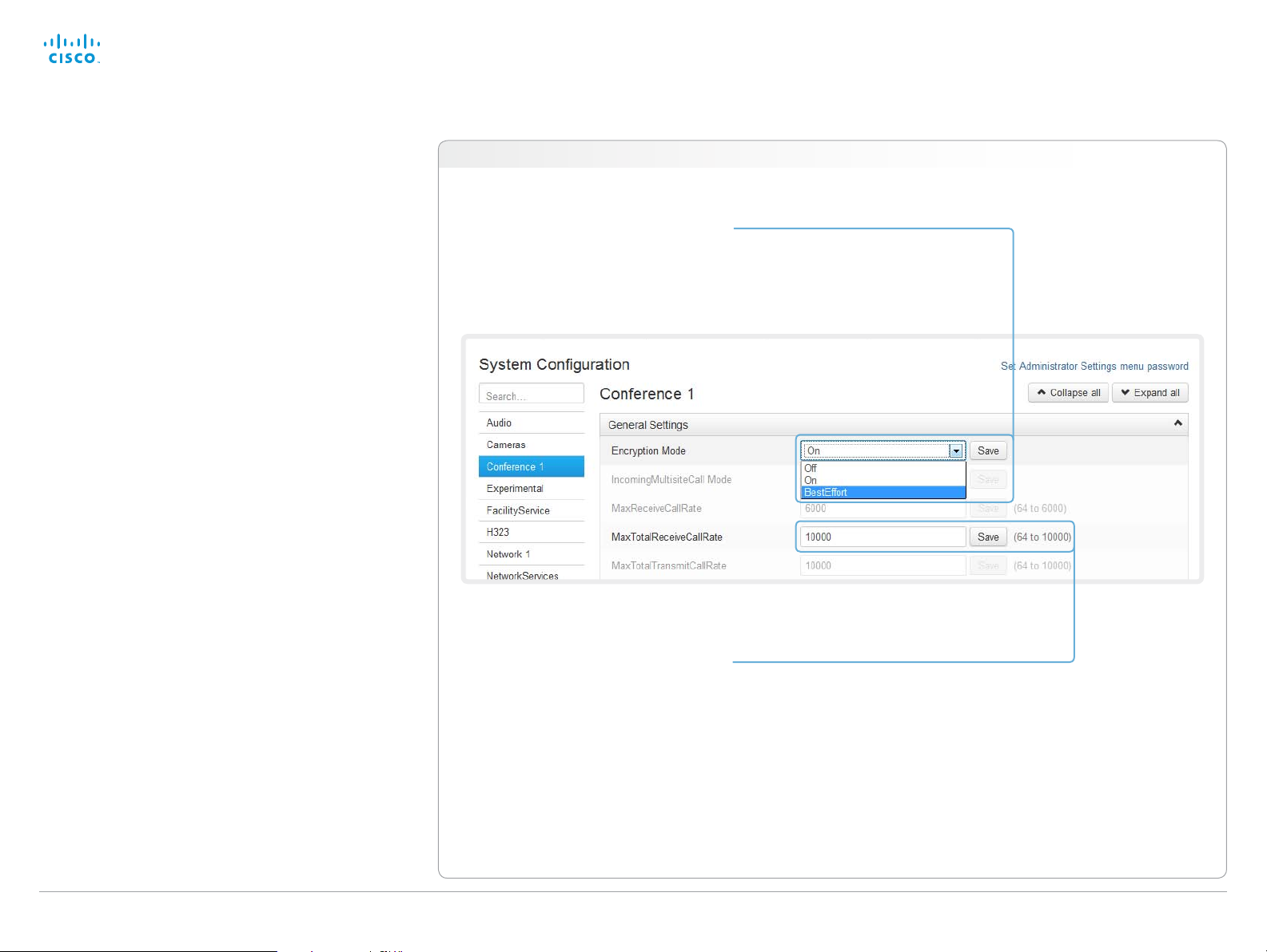
Changing system settings
All system settings can be changed from the System
Configuration page. The value space for a setting is specified
either as a drop-down list or with explanatory text following a
text input field.
Different settings may require different user credentials. In
order to be sure that an administrator is able to change all
system settings, the user must possess all user roles.
You can read more about user administration and user roles
in the ► User administration ch a pter.
Navigate to: Configuration > System Configuration
Drop-down list
Click the arrow to open the drop-down
list. Choose the preferred value and click
Save for the change to take effect.
Text input field
Enter text in the input field and click Save
for the change to take effect.
D14908.02 SX20 Administrator Guide TC6.0, JANUARY 2013. www.cisco.com — Copyright © 2012-2013 Cisco Systems, Inc. All rights reserved.
24
Page 25

Cisco TelePresence SX20 Quick Set Administrator Guide
Contents
Introduction
Web interface
System settings
Setting passwords
Appendices
Web interface
Setting the Administrator Settings menu password
When starting up the video conference system for the first
time anyone can access the Administrator Settings menu with
either the remote control or the Touch controller because the
menu password is not set.
We strongly recommend that you define a menu
password, because the Administrator Settings may
severely affect the behavior of the video conference
system.
You can read more about password protection in the
► Setting passwords chapt er.
Navigate to: Configuration > System Configuration
Changing the menu password
Click Set/Change Administrator
Settings menu password to open
this dialog.
Enter a new password in the text
input field and click Save to store it.
Use the Unlock button to clear the
existing password.
D14908.02 SX20 Administrator Guide TC6.0, JANUARY 2013. www.cisco.com — Copyright © 2012-2013 Cisco Systems, Inc. All rights reserved.
25
Page 26
Cisco TelePresence SX20 Quick Set Administrator Guide
Contents
Introduction
Web interface
System settings
Setting passwords
Appendices
Web interface
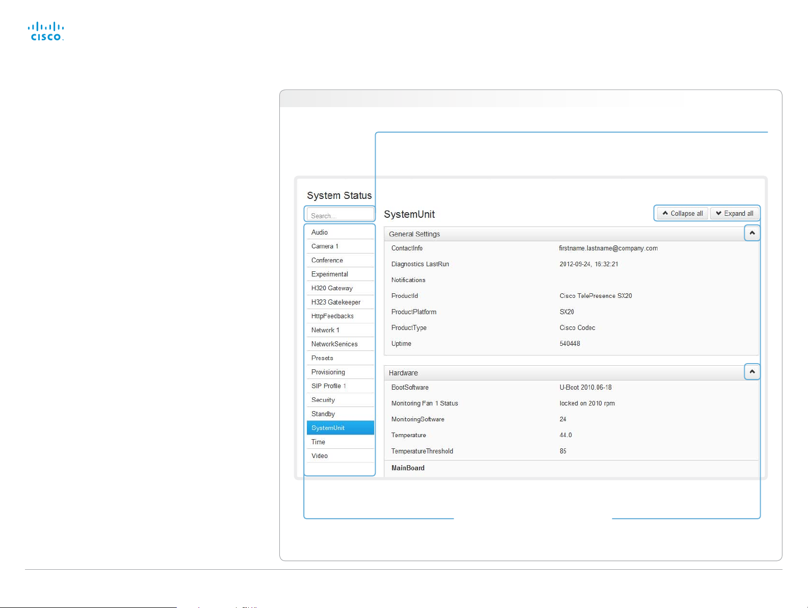
System status
The system status is grouped in several categories. When
you choose a category in the left column, the related status
appears in the window to the right.
Navigate to: Configuration > System Status
Searching for status entries
Enter as many letters as needed in the search field. All
entries containing these letters will be highlighted.
Selecting a category
The system status is structured in
several categories. Choose a category
to display the related status information.
D14908.02 SX20 Administrator Guide TC6.0, JANUARY 2013. www.cisco.com — Copyright © 2012-2013 Cisco Systems, Inc. All rights reserved.
26
Expanding and collapsing lists
Use the buttons to expand and collapse
all or individual lists.
Page 27

Cisco TelePresence SX20 Quick Set Administrator Guide
Contents
Introduction
Web interface
System settings
Setting passwords
Appendices
Web interface
Choosing a wallpaper
You can choose from a set of predefined wallpapers to use
as background on your display.
If you want the company logo or another custom picture to
be displayed on the main display, you may upload and use a
custom wallpaper.
If you use the Touch controller: The custom wallpaper applies
to only the main display and will not appear on the Touch
controller.
Navigate to: Configuration > Personalization : Wallpaper tab
Uploading a custom wallpaper file
Click Brows e... and locate your custom
wallpaper image file.
The file format must be .png and the maximum
image size is 1920 × 1200 pixels.
Click Upload to save the file to the video system.
D14908.02 SX20 Administrator Guide TC6.0, JANUARY 2013. www.cisco.com — Copyright © 2012-2013 Cisco Systems, Inc. All rights reserved.
27
Choosing a wallpaper
Choose a wallpaper from the list.
If you have uploaded a custom wallpaper,
it will appear in the list together with the
predefined wallpapers.
The chosen wallpaper is highlighted.
Page 28
Cisco TelePresence SX20 Quick Set Administrator Guide
Contents
Introduction
Web interface
System settings
Setting passwords
Appendices
Web interface
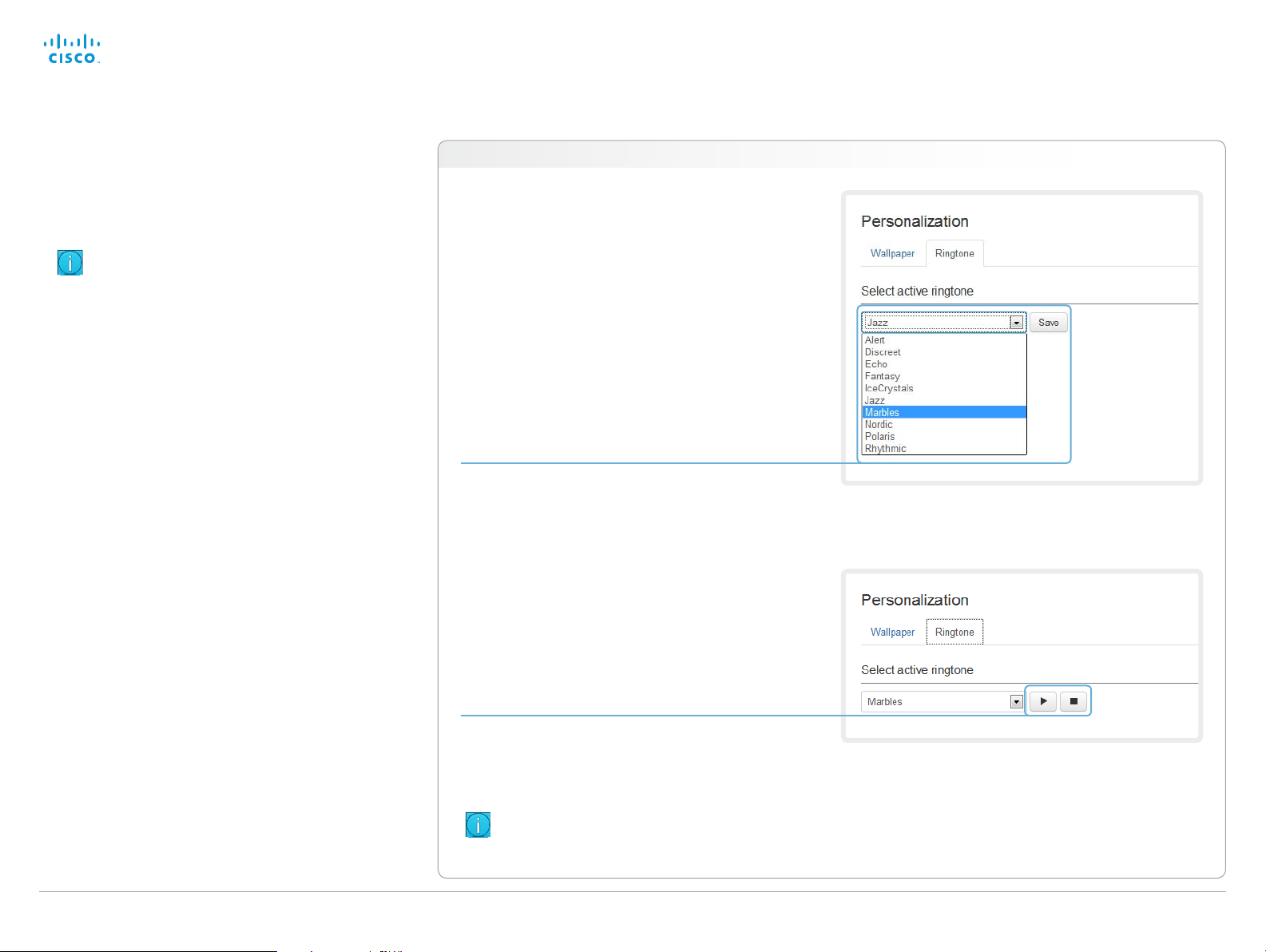
Choosing a ringtone
You can choose from a set of predefined ringtones. The
chosen ringtone can be played back from this page.
Even if the web interface is used to initiate the
playback it is the video system that plays back the
ringtone; it is not the PC running the web interface.
Navigate to: Configuration > Personalization : Ringtone tab
Choosing a ringtone
Choose a ringtone from the drop-down list,
and click Save to make it the active ringtone.
Playing back a ringtone
Click the play button ( ► ) to play back the
ringtone.
Use the stop button ( ) to end the playback.
You must save the ringtone before it
can be played back.
D14908.02 SX20 Administrator Guide TC6.0, JANUARY 2013. www.cisco.com — Copyright © 2012-2013 Cisco Systems, Inc. All rights reserved.
28
Page 29
Cisco TelePresence SX20 Quick Set Administrator Guide
Contents
Introduction
Web interface
System settings
Setting passwords
Appendices
Web interface
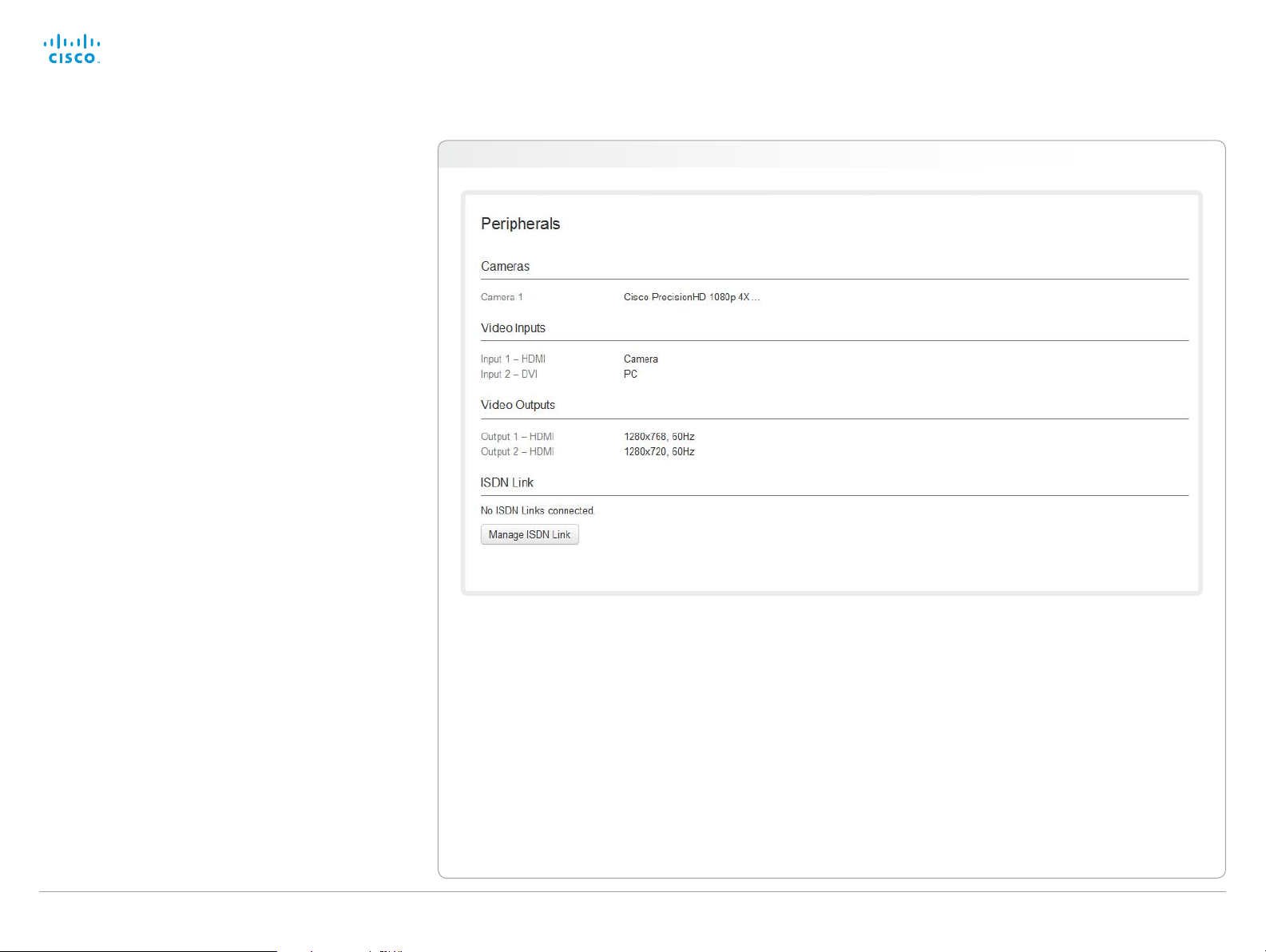
Peripherals overview
This page shows an overview of the video input and video
output configuration, as well as information about any
camera(s), Touch controller or ISDN Link that is connected to
your video system.
The illustration to the right is an example; your system
may have different peripherals and video input/output
configurations.
Managing ISDN Link
If an ISDN Link is paired to the video system it can be
managed from this page.
How to configure and use the ISDN Link are
described in the ISDN Link documentation on
► http://www.cisco.com/go/isdnlink-docs
Navigate to: Configuration > Peripherals
D14908.02 SX20 Administrator Guide TC6.0, JANUARY 2013. www.cisco.com — Copyright © 2012-2013 Cisco Systems, Inc. All rights reserved.
29
Page 30
Cisco TelePresence SX20 Quick Set Administrator Guide
Contents
Introduction
Web interface
System settings
Setting passwords
Appendices
Web interface
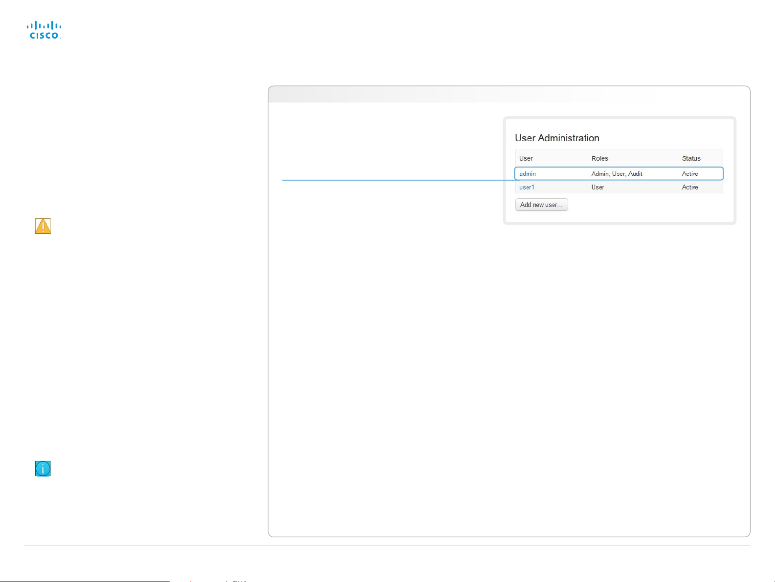
User administration
From this page you can manage the user accounts of your
video conference system. You can create new user accounts,
edit the details of existing users, and delete users.
The default user account
The system comes with a default administrator user account
with full access rights. The username is admin and no
password is set.
It is highly recommended to set a password for the
admin us e r.
Read more about passwords in the ► Setting passwords
ch a pter.
About user roles
A user account must hold one or a combination of several
user roles.
The following three user roles, with non-overlapping rights,
exist:
• ADMIN: A user holding this role can create new users and
change most settings. The user neither can upload audit
certificates nor change the security audit settings.
• USER: A user holding this role can make calls and search
the phone book. The user can modify a few settings,
e.g. adjusting the audio volume and changing the menu
language.
• AUDIT: A user holding this role can change the security
audit configurations and upload audit certificates.
Navigate to: Configuration > User Administration
Default user account
The system comes with admin as the default
user account. This user has full access rights.
An administrator user account with full access rights,
like the default admin user, must possess all the three
roles.
D14908.02 SX20 Administrator Guide TC6.0, JANUARY 2013. www.cisco.com — Copyright © 2012-2013 Cisco Systems, Inc. All rights reserved.
30
Page 31

Cisco TelePresence SX20 Quick Set Administrator Guide
Contents
Introduction
Web interface
System settings
Setting passwords
Appendices
Web interface
User administration, continued
Creating a new user account
Follow these steps in order to create a new user account:
1. Click Add new user....
2. Fill in the Username, Password and PIN code, and check
the appropriate user roles check boxes.
As a default the user has to change the password and
PIN code when signing in for the first time.
Do not fill in the Distinguished Name (DN) Subject field
unless you want to use certificate login on https.
3. Set the Status to Active to activate the user.
4. Click Save to save the changes.
Navigate to: Configuration > User Administration
D14908.02 SX20 Administrator Guide TC6.0, JANUARY 2013. www.cisco.com — Copyright © 2012-2013 Cisco Systems, Inc. All rights reserved.
31
Page 32

Cisco TelePresence SX20 Quick Set Administrator Guide
Contents
Introduction
Web interface
System settings
Setting passwords
Appendices
Web interface
User administration, continued
Editing user details
Follow these steps in order to edit an existing user account:
1. Click the name of an existing user to open the Editing
user window.
2. Edit the details.
3. Click Save to save the changes or Cancel to go back one
step without storing the information.
Deactivating a user account
Follow these steps in order to deactivate a user account:
Always keep at least one user with ADMIN rights
Active.
1. Open the Editing user window by clicking the name of the
us e r.
2. Set the Status to Inactive.
3. Click Save to save the changes.
Navigate to: Configuration > User Administration
Deleting a user account
Follow these steps in order to delete a user account:
Always keep at least one user with ADMIN rights.
1. Open the Editing user window by clicking the name of the
us e r.
2. Click Delete.
D14908.02 SX20 Administrator Guide TC6.0, JANUARY 2013. www.cisco.com — Copyright © 2012-2013 Cisco Systems, Inc. All rights reserved.
32
Page 33

Cisco TelePresence SX20 Quick Set Administrator Guide
Contents
Introduction
Web interface
System settings
Setting passwords
Appendices
Web interface
Adding a sign in banner
A sign in banner is a message that is displayed to the user
when signing in.
If a system administrator wants to provide initial information
to all users, he can create a sign in banner. The message will
be shown when the user signs in to the web interface or the
command line interface.
Navigate to: Configuration > Sign In Banner
Adding a sign in banner
Enter the message that you
want to present to the user
when signing in, and click
Save to activate the banner.
D14908.02 SX20 Administrator Guide TC6.0, JANUARY 2013. www.cisco.com — Copyright © 2012-2013 Cisco Systems, Inc. All rights reserved.
33
Page 34

Cisco TelePresence SX20 Quick Set Administrator Guide
Contents
Introduction
Web interface
System settings
Setting passwords
Appendices
Web interface
Application programming interface
The application programming interface (API) is a tool for
integration professionals and developers working with this
Cisco product. It is described in detail in the API guide for the
product.
XML files
The XML files are part of the codec’s API. They structure
information about the codec in a hierarchy.
• Configuration.xml contains the current system settings
(configuration). These settings are controlled from the
web interface or from the API (Application Programmer
Interface).
• The information in status.xml is constantly updated by
the system to reflect system and process changes. The
status information is normally monitored from the API.
• Command.xml contains an overview of the commands
available to instruct the system to perform an action. The
commands are issued from the API.
• Valuespace.xml contains an overview of all the value
spaces used in the system settings, status information,
and commands.
API commands
Commands (xCommand) and configurations (xConfiguration)
can be executed from this web page. Syntax and semantics
are explained in the API guide for the product.
Navigate to: Configuration > API
Opening an XML file
Click the file name to open the XML file.
Executing API commands
Enter a command, or a sequence of
commands, in the text area and click
Execute to issue the command(s).
D14908.02 SX20 Administrator Guide TC6.0, JANUARY 2013. www.cisco.com — Copyright © 2012-2013 Cisco Systems, Inc. All rights reserved.
34
Page 35

Cisco TelePresence SX20 Quick Set Administrator Guide
Contents
Introduction
Web interface
System settings
Setting passwords
Appendices
Web interface
Managing the video system’s certificates
Certificate validation may be required when using TLS
(Transport Layer Security).
A server or client may require that your video system
presents a valid certificate to them before communication can
be set up.
The video system’s certificates are text files that verify the
authenticity of the system. These certificates may be issued
by a certificate authority (CA).
The certificate are listed as shown in the illustration to the
*
. They can be used for the following services: HTTPS,
right
SIP and IEEE 802.1X.
You can store several certificates on the system, but only one
certificate can be used for each service at a time.
If authentication fails, the connection will not be established.
Navigate to: Configuration > Security
Enabling and disabling certificates
Use the buttons to switch a
certificate on or off for the different
services.
You can also view a certificate,
and delete a certificate using the
corresponding buttons.
Adding a certificate
1. Click Add certificate... to open the certificate dialog.
2. Click Browse... and find the Certificate and
4. Click Add certificate... to store the certificate
*
The cer tificates and certificate issuers shown in the illustration
serve as examples. Your system may have other certificate(s).
D14908.02 SX20 Administrator Guide TC6.0, JANUARY 2013. www.cisco.com — Copyright © 2012-2013 Cisco Systems, Inc. All rights reserved.
Private key file(s) on your computer.
3. Fill in the Password if required.
on your system.
35
Contact your system administrator to obtain the
following file(s):
• Certificate (file format: .PEM)
• Private key, may be included in the same file as
the certificate (file format: .PEM format)
• Password (required only if the private key is
encrypted)
The certificate and the private key will be stored in
the same file on the video system.
Page 36
Cisco TelePresence SX20 Quick Set Administrator Guide
Contents
Introduction
Web interface
System settings
Setting passwords
Appendices
Web interface
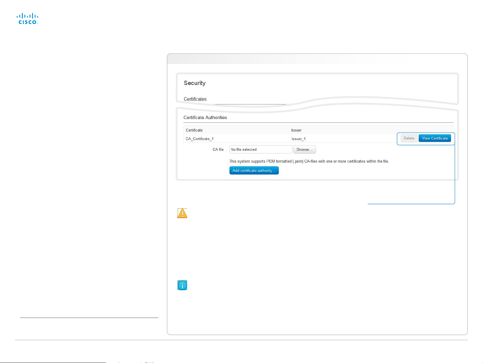
Managing the list of trusted certificate authorities
Certificate validation may be required when using TLS
(Transport Layer Security).
Your video system may be set up to require that a server
or client presents its certificate to the system before
communication can be set up.
The certificates are text files that verify the authenticity of the
server or client. The certificates must be signed by a trusted
certificate authority (CA).
To be able to verify the signature of the certificates, a list of
trusted CAs must reside on the video system. The certificates
of the CAs are listed as shown in the illustration to the right
The list must include CAs to verify certificates for as well
HTTPS, SIP and IEEE 802.1X connections.
If the server cannot be authenticated, the connection will not
be established.
*
.
Navigate to: Configuration > Security
Uploading a list of certificate authorities
The entries in a new file with CA cer tificates will be
appended to the existing list, that is, the previously
stored certificates will not be deleted.
i. Click Show CAs... to list the existing CA certificates.
ii. Click Add Certificate Authority....
iii. Click B rowse... and find the file containing a list of CA
certificates (file format: .PEM) on your computer.
iv. Click Add certificate authority... to store the new CA
certificate(s) on your system.
Viewing and deleting certificates
You can view a certificate, and
delete a certificate using the
corresponding buttons.
Contact your system administrator to obtain the
CA certificate list (file format: .PEM).
*
The cer tificate and certif icate issuers shown in the illustration serve
as examples. Your system will have other certificate(s).
D14908.02 SX20 Administrator Guide TC6.0, JANUARY 2013. www.cisco.com — Copyright © 2012-2013 Cisco Systems, Inc. All rights reserved.
36
Page 37

Cisco TelePresence SX20 Quick Set Administrator Guide
Contents
Introduction
Web interface
System settings
Setting passwords
Appendices
Web interface
Adding audit certificates
Audit logging records all sign in activity and configuration
changes on your video system.
Audit logging is disabled by default, but you can enable it
using the Security > Audit > Logging > Mode setting on the
on-screen menu or the web interface.
In ExternalSecure audit logging mode the video system
sends encrypted audit logs to an external audit server
(syslog server), which identity must be verified by a signed
certificate.
To be able to verify the signature of the audit server
certificates, a list of trusted audit certificate authorities (CAs)
must reside on the video system.
If the audit server cannot be authenticated, the logs will not
be sent.
Always upload the audit certificate list before enabling
secure audit logging.
Navigate to: Configuration > Security / Configuration > System Configuration
iii
ii
1. Upload a list of audit server certificates
The entries in a new file with CA
certificates will overwrite the existing
list, that is, any previously stored audit
certificates will be lost when you add a
new file.
i. Click Add audit server certificate authority....
ii. Click Brows e... and find the file containing the
list of audit CA certificates (.PEM format) on
your computer.
iii. Click Add audit certificate to store the
certificate(s) on your system.
Contact your system administrator to
obtain the Audit CA list (file format: .PEM).
2. Enable secure audit
logging
i. Go to the System
Configuration page and
choose the Security
category.
ii. Enter the Address and
Port number of the audit
server. Click Save for the
changes to take effect.
iii. Choose ExternalSecure
from the Logging Mode
drop-down list. Click
Save for the change to
take effect.
i
D14908.02 SX20 Administrator Guide TC6.0, JANUARY 2013. www.cisco.com — Copyright © 2012-2013 Cisco Systems, Inc. All rights reserved.
37
Page 38

Cisco TelePresence SX20 Quick Set Administrator Guide
Contents
Introduction
Web interface
System settings
Setting passwords
Appendices
Web interface
Setting strong security mode
Strong security mode should be used only when compliance
with DoD JITC regulations is required.
Read the warning carefully before setting strong
security mode.
Strong security mode sets very strict password requirements,
and requires all users to change their password on the next
sign in.
Software upload from TMS, web snapshots and calling from
the web interface are prohibited in strong security mode.
Navigate to: Configuration > Security
Setting strong security mode
1. Click Configure strong security mode...
and read the warning carefully before
continuing.
2. If you want to use strong security
mode, check the Iunderstand the risks
of strong security mode check box and
click Enable strong security mode.
3. Change the password to meet the
strict criteria shown in the warning.
How to change the system password:
see the ► Setting passwords section.
4. Restart the codec for the change to
take effect.
Return to normal mode
1. When in strong security mode,
the system can be restored
to normal mode by clicking
Configure strong security mode...
followed by Disable strong
security mode.
2. Restart the codec for the change
to take effect.
D14908.02 SX20 Administrator Guide TC6.0, JANUARY 2013. www.cisco.com — Copyright © 2012-2013 Cisco Systems, Inc. All rights reserved.
38
Page 39

Cisco TelePresence SX20 Quick Set Administrator Guide
Contents
Introduction
Web interface
System settings
Setting passwords
Appendices
Web interface
Deleting trust lists (CUCM only)
The Cisco Unified Communications Manager (CUCM) and
Certification Authority Proxy Function (CAPF) information
that is shown on the Security page is only relevant for video
systems that are registered to CUCM.
The web interface can be used to delete an existing
Certificate Trust List (CTL) that is stored on the video system.
Normally, you will not delete the old CTL file, but there are a
few cases when you will need to delete it.
For more information about CUCM, CAPF and trust lists, read
the Administering TC Endpoints on CUCM guide available on
the Cisco web site.
Navigate to: Configuration > Security
D14908.02 SX20 Administrator Guide TC6.0, JANUARY 2013. www.cisco.com — Copyright © 2012-2013 Cisco Systems, Inc. All rights reserved.
39
Page 40

Cisco TelePresence SX20 Quick Set Administrator Guide
Contents
Introduction
Web interface
System settings
Setting passwords
Appendices
Web interface
Troubleshooting
The troubleshooting page lists the status for some common
sources of errors. The list may be different for different
products and installations.
Errors are clearly marked in red color, and warnings are
yellow.
Navigate to: Diagnostics > Troubleshooting
Run diagnostics
Click Re-run diagnostics to make
sure the information in the list is
up-to-date.
D14908.02 SX20 Administrator Guide TC6.0, JANUARY 2013. www.cisco.com — Copyright © 2012-2013 Cisco Systems, Inc. All rights reserved.
40
Page 41
Cisco TelePresence SX20 Quick Set Administrator Guide
Contents
Introduction
Web interface
System settings
Setting passwords
Appendices
Web interface
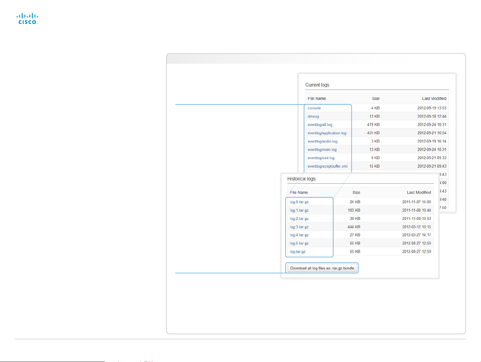
Downloading log files
The log files are Cisco specific debug files which may be
requested by the Cisco support organization if you need
technical support.
The current log files are time stamped event log files.
All current log files are archived in a time stamped historical
log file each time the system reboots. If the maximum
number of historical log files is reached, the oldest one will be
overwritten.
Navigate to: Diagnostics > Log Files
Downloading one file
Click the file name and follow the
instructions to save or open the file (left
or right click depending on your browser).
Downloading all files
Click Download all log files as .tar.gz bundle
and follow the instructions.
D14908.02 SX20 Administrator Guide TC6.0, JANUARY 2013. www.cisco.com — Copyright © 2012-2013 Cisco Systems, Inc. All rights reserved.
41
Page 42

Cisco TelePresence SX20 Quick Set Administrator Guide
Contents
Introduction
Web interface
System settings
Setting passwords
Appendices
Web interface
Upgrading the system software
This video conference system is using TC software. The
version described in this document is TC6.0.
Contact your system administrator if you have
questions about the software version.
Software release notes
For a complete overview of the news and changes, we
recommend reading the Software Release Notes (TC6).
Go to: ► http://www.cisco.com/en/US/products/ps11424/
tsd_products_support_series_home.html
New software
For software download, go to the
Cisco Download Software web page:
► http://www.cisco.com/cisco/software/navigator.html. Then
navigate to your product.
The file name is something like “s52010tc6_0_0.pkg” (each
software version has a unique file name).
Release key and option keys
The release key is required to be able to use the software. A
new release key is required for every major software release
(e.g. when upgrading from TC5.x or older to TC6.x).
An option key is required to activate optional functionality. You
may have several option keys in your system.
The available options are:
• Premium resolution
• MultiSite
• Dual display
Contact your Cisco representative to obtain the required
release key and option keys.
Navigate to: Maintenance > Software Upgrade
1. Add the release and option keys
Contact your Cisco representative to obtain the required
key(s). Then perform the following steps:
i. Enter the Release key in the appropriate text input field
and click Add.
ii. Enter an Option Key in the appropriate text input field
and click Add.
If you have more than one option key, repeat step ii for
all of them.
Each system has unique keys.
Release key format: “1TC005-1-0C22E348”
Option key format: “1N000-1-AA7A4A09”
2. Install new software
Download the appropriate software package from the Cisco
Software Download web page (see link to the left) before
you start the software upgrade as described in these steps:
i. Click Brows e... and find the .pkg file containing the new
soft ware.
ii. Check the Upgrade automatically after upload check
box, then click Upload to start the installation process
straight away.
Keep the check box unchecked if you want to upload
the software now and do the installation later.
The complete installation may take up to 30minutes. You
can follow the progress on the web page. The system
reboots automatically after the installation.
You must sign in anew in order to continue working
with the web interface after the reboot.
D14908.02 SX20 Administrator Guide TC6.0, JANUARY 2013. www.cisco.com — Copyright © 2012-2013 Cisco Systems, Inc. All rights reserved.
42
Page 43
Cisco TelePresence SX20 Quick Set Administrator Guide
Contents
Introduction
Web interface
System settings
Setting passwords
Appendices
Web interface
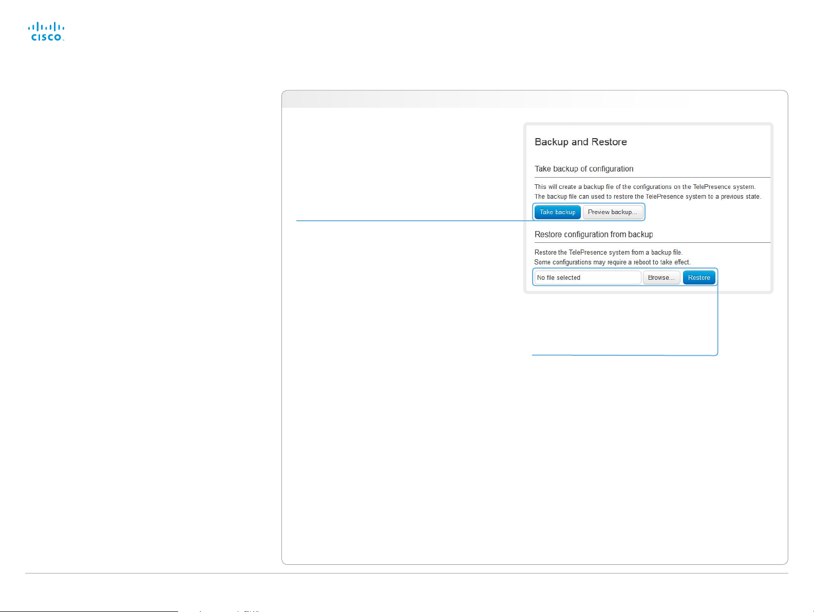
Backup and restore
All the system settings, which are available on the System
configuration page, can be listed on-screen or stored as a
text file (.tsh).
The .tsh file can be loaded back onto the system, thereby
restoring the old configuration.
Navigate to: Maintenance > Backup and Restore
Backing up or showing the current configuration
Click Preview b acku p... to display the current
settings on-screen.
Click Take backup to store the configuration
as a text file (.tsh).
Restoring an earlier configuration
Click Brows e... and find the file (.tsh) with
the configuration you want to restore.
Click Restore to reconfigure the system as
defined in the file.
D14908.02 SX20 Administrator Guide TC6.0, JANUARY 2013. www.cisco.com — Copyright © 2012-2013 Cisco Systems, Inc. All rights reserved.
43
Page 44

Cisco TelePresence SX20 Quick Set Administrator Guide
Contents
Introduction
Web interface
System settings
Setting passwords
Appendices
Web interface
Factory reset
When performing a factory reset the call logs will be deleted
and all system parameters will be reset to default values. All
files that have been uploaded to the system will be deleted.
Release keys and option keys will be preserved.
It is not possible to undo a factory reset.
There are more information about performing a factory reset
in the ► Factory resetting appendix.
Navigate to: Maintenance > Factory Reset
Perform a factory reset
1. Read the provided information
carefully before you restore the
factory settings by clicking Perform
a factory reset.
2. Click Reset to confirm your choice,
or Cancel if you have changed your
mind.
Wait while the system resets. The
system will restart automatically
when finished.
D14908.02 SX20 Administrator Guide TC6.0, JANUARY 2013. www.cisco.com — Copyright © 2012-2013 Cisco Systems, Inc. All rights reserved.
44
Page 45

Cisco TelePresence SX20 Quick Set Administrator Guide
Contents
Introduction
Web interface
System settings
Setting passwords
Appendices
Web interface
Restarting the system
The system can be shut down or restarted remotely using the
web interface.
Navigate to: Maintenance > Restart
Restarting the system
Click Restart TelePresence device to
restart the system.
It will take a few minutes before
the system is ready for use.
Shutting down the system
Click Shutdown TelePresence device to
shut down the system.
The system cannot be turned on
again remotely; you must press
its power button physically to
turn it on.
D14908.02 SX20 Administrator Guide TC6.0, JANUARY 2013. www.cisco.com — Copyright © 2012-2013 Cisco Systems, Inc. All rights reserved.
45
Page 46

Cisco TelePresence SX20 Quick Set Administrator Guide
Contents
Introduction
Web interface
System settings
Setting passwords
Appendices
System settings
Chapter 3
System settings
D14908.02 SX20 Administrator Guide TC6.0, JANUARY 2013. www.cisco.com — Copyright © 2012-2013 Cisco Systems, Inc. All rights reserved.
46
Page 47

Cisco TelePresence SX20 Quick Set Administrator Guide
Contents
Introduction
Web interface
System settings
Setting passwords
Appendices
System settings
Overview of the system settings
In the following pages you will find a complete list of the
system settings which are configured from the System
Configuration page on the web interface. The examples show
either the default value or an example of a value.
Open a web browser and enter the IP address of the video
system then sign in.
Navigate to Home > Settings > System Information
using the remote control and on-screen menu, or
tap Settings (
controller to find the system’s IP address (IPv4
orIPv6).
) > System Information on the Touch
Audio settings ...................................................................... 50
Audio Input HDMI [1] Mode .................................................... 50
Audio Microphones Mute Enabled ......................................... 50
Audio SoundsAndAlerts KeyTones Mode .............................. 50
Audio SoundsAndAlerts RingTone ......................................... 50
Audio SoundsAndAlerts RingVolume.....................................50
Audio Volume ......................................................................... 50
Cameras settings ................................................................. 51
Cameras Camera [1..1] Backlight ........................................... 51
Cameras Camera [1..1] Brightness Level ............................... 51
Cameras Camera [1..1] Brightness Mode ............................... 51
Cameras Camera [1..1] DHCP ................................................ 53
Cameras Camera [1..1] Flip .................................................... 51
Cameras Camera [1..1] Focus Mode ...................................... 51
Cameras Camera [1..1] Gamma Level .................................... 52
Cameras Camera [1..1] Gamma Mode ................................... 52
Cameras Camera [1..1] IrSensor ............................................52
Cameras Camera [1..1] Mirror ................................................ 52
Cameras Camera [1..1] Whitebalance Level ........................... 52
Cameras Camera [1..1] Whitebalance Mode .......................... 52
Cameras PowerLine Frequency ............................................. 51
Conference settings ............................................................ 54
Conference [1..1] AutoAnswer Delay ...................................... 54
Conference [1..1] AutoAnswer Mode ..................................... 54
Conference [1..1] AutoAnswer Mute ....................................... 54
Conference [1..1] DefaultCall Protocol .................................... 55
Conference [1..1] DefaultCall Rate .......................................... 55
Conference [1..1] DoNotDisturb DefaultTimeout .................... 55
Conference [1..1] DoNotDisturb Mode ................................... 54
Conference [1..1] Encryption Mode ........................................ 55
Conference [1..1] FarEndControl Mode .................................. 55
Conference [1..1] FarEndControl SignalCapability .................. 55
Conference [1..1] IncomingMultisiteCall Mode ....................... 58
Conference [1..1] MaxReceiveCallRate ..................................56
Conference [1..1] MaxTotalReceiveCallRate ........................... 56
Conference [1..1] MaxTotalTransmitCallRate ..........................56
Conference [1..1] MaxTransmitCallRate .................................. 56
Conference [1..1] MicUnmuteOnDisconnect Mode ................ 54
Conference [1..1] Multipoint Mode ......................................... 58
Conference [1..1] PacketLossResilience Mode ...................... 57
Conference [1..1] Presentation OnPlacedOnHold .................. 57
Conference [1..1] Presentation Policy ..................................... 57
Conference [1..1] Presentation RelayQuality .......................... 57
Conference [1..1] VideoBandwidth MainChannel Weight ....... 56
Conference [1..1] VideoBandwidth Mode ............................... 56
Conference [1..1] VideoBandwidth PresentationChannel
Weight .................................................................................... 57
FacilityService settings ........................................................ 59
FacilityService Service [1..5] CallType ...................................59
FacilityService Service [1..5] Name ....................................... 59
FacilityService Service [1..5] Number .................................... 59
FacilityService Service [1..5] Type .........................................59
H323 settings .......................................................................60
H323 NAT Address ................................................................ 60
H323 NAT Mode .................................................................... 60
H323 Profile [1..1] Authentication LoginName ........................ 60
H323 Profile [1..1] Authentication Mode ................................. 60
H323 Profile [1..1] Authentication Password .......................... 61
H323 Profile [1..1] CallSetup Mode ......................................... 61
H323 Profile [1..1] Gatekeeper Address ................................. 61
H323 Profile [1..1] Gatekeeper Discovery ............................... 61
H323 Profile [1..1] H323Alias E164 ......................................... 61
H323 Profile [1..1] H323Alias ID .............................................. 62
H323 Profile [1..1] PortAllocation ............................................ 62
Network settings .................................................................. 63
Network [1..1] Assignment ...................................................... 63
Network [1..1] DNS Domain Name .......................................... 64
Network [1..1] DNS Server [1..3] Address ............................... 64
Network [1..1] IEEE8021X AnonymousIdentity ........................ 67
Network [1..1] IEEE8021X Eap Md5 ........................................ 67
Network [1..1] IEEE8021X Eap Peap ....................................... 67
Network [1..1] IEEE8021X Eap Tls ........................................... 67
Network [1..1] IEEE8021X Eap Ttls .......................................... 67
Network [1..1] IEEE8021X Identity ........................................... 67
D14908.02 SX20 Administrator Guide TC6.0, JANUARY 2013. www.cisco.com — Copyright © 2012-2013 Cisco Systems, Inc. All rights reserved.
47
Page 48

Cisco TelePresence SX20 Quick Set Administrator Guide
Contents
Introduction
Web interface
System settings
Setting passwords
Appendices
System settings
Network [1..1] IEEE8021X Mode ............................................. 66
Network [1..1] IEEE8021X Password ....................................... 67
Network [1..1] IEEE8021X TlsVerify ......................................... 66
Network [1..1] IEEE8021X UseClientCertificate ...................... 66
Network [1..1] IPStack ............................................................. 63
Network [1..1] IPv4 Address ................................................... 63
Network [1..1] IPv4 Gateway ................................................... 63
Network [1..1] IPv4 SubnetMask ............................................. 63
Network [1..1] IPv6 Address ................................................... 64
Network [1..1] IPv6 Assignment .............................................. 63
Network [1..1] IPv6 DHCPOptions .......................................... 64
Network [1..1] IPv6 Gateway ................................................... 64
Network [1..1] MTU ................................................................. 68
Network [1..1] QoS Diffserv Audio .......................................... 65
Network [1..1] QoS Diffserv Data ............................................ 65
Network [1..1] QoS Diffserv ICMPv6 ...................................... 66
Network [1..1] QoS Diffserv NTP ............................................ 66
Network [1..1] QoS Diffserv Signalling .................................... 65
Network [1..1] QoS Diffserv Video .......................................... 65
Network [1..1] QoS Mode ....................................................... 64
Network [1..1] RemoteAccess Allow ....................................... 68
Network [1..1] Speed .............................................................. 68
Network [1..1] TrafficControl Mode ......................................... 68
Network [1..1] VLAN Voice Mode ........................................... 68
Network [1..1] VLAN Voice VlanId........................................... 68
NetworkServices settings .................................................... 69
NetworkServices CTMS Encryption ...................................... 73
NetworkServices CTMS Mode .............................................. 72
NetworkServices H323 Mode ............................................... 69
NetworkServices HT TP Mode ............................................... 69
NetworkServices HT TPS Mode ............................................. 70
NetworkServices HT TPS OCSP Mode .................................. 70
NetworkServices HT TPS OCSP URL .................................... 70
NetworkServices HTTPS VerifyClientCertificate ................... 70
NetworkServices HTTPS VerifyServerCertificate ................. 70
NetworkServices MultiWay Address ..................................... 69
NetworkServices MultiWay Protocol ..................................... 69
NetworkServices NTP Address ............................................. 71
NetworkServices NTP Mode ................................................. 71
NetworkServices SIP Mode ................................................... 71
NetworkServices SNMP CommunityName ........................... 71
NetworkServices SNMP Host [1..3] Address ......................... 71
NetworkServices SNMP Mode .............................................. 71
NetworkServices SNMP SystemContact ..............................72
NetworkServices SNMP SystemLocation ............................. 72
NetworkServices SSH AllowPublicKey .................................. 72
NetworkServices SSH Mode ................................................. 72
NetworkServices Telnet Mode .............................................. 72
NetworkServices XMLAPI Mode ........................................... 69
Phonebook settings ............................................................. 74
Phonebook Server [1..1] ID ..................................................... 74
Phonebook Server [1..1] Type ................................................ 74
Phonebook Server [1..1] URL ................................................. 74
Provisioning settings ............................................................ 75
Provisioning Connectivity ...................................................... 75
Provisioning ExternalManager Address ................................. 76
Provisioning ExternalManager Domain .................................. 76
Provisioning ExternalManager Path ....................................... 76
Provisioning ExternalManager Protocol ................................. 76
Provisioning HttpMethod .......................................................75
Provisioning LoginName ........................................................ 75
Provisioning Mode ................................................................. 75
Provisioning Password ........................................................... 75
RTP settings ......................................................................... 77
RTP Ports Range Start ........................................................... 77
RTP Ports Range Stop ........................................................... 77
Security settings .................................................................. 78
Security Audit Logging Mode ................................................ 78
Security Audit OnError Action ................................................ 78
Security Audit Server Address .............................................. 78
Security Audit Server Port ..................................................... 78
Security Session InactivityTimeout ........................................ 79
Security Session ShowLastLogon ......................................... 79
SerialPort settings ............................................................... 80
SerialPort BaudRate ............................................................... 80
SerialPort LoginRequired ....................................................... 80
SerialPort Mode ..................................................................... 80
SIP settings .......................................................................... 81
SIP ListenPort ........................................................................ 81
SIP Profile [1..1] Authentication [1..1] LoginName ................... 81
SIP Profile [1..1] Authentication [1..1] Password ...................... 81
SIP Profile [1..1] DefaultTransport ........................................... 81
SIP Profile [1..1] DisplayName................................................. 81
SIP Profile [1..1] Outbound ...................................................... 82
SIP Profile [1..1] Proxy [1..4] Address ...................................... 82
SIP Profile [1..1] Proxy [1..4] Discovery ................................... 82
SIP Profile [1..1] TlsVerify ........................................................ 82
SIP Profile [1..1] Type .............................................................. 82
SIP Profile [1..1] URI ................................................................ 81
Standby settings .................................................................. 83
Standby BootAction ...............................................................83
Standby Control .....................................................................83
Standby Delay ........................................................................ 83
Standby StandbyAction ......................................................... 83
Standby WakeupAction .......................................................... 83
SystemUnit settings ............................................................. 84
SystemUnit CallLogging Mode .............................................. 84
SystemUnit ContactInfo Type ................................................84
SystemUnit IrSensor .............................................................. 85
SystemUnit MenuLanguage ...................................................84
SystemUnit Name .................................................................. 84
Time settings ....................................................................... 86
Time DateFormat ................................................................... 86
Time TimeFormat ................................................................... 86
Time Zone .............................................................................. 86
UserInterface settings .......................................................... 87
UserInterface TouchPanel DefaultPanel ................................ 87
Video settings ...................................................................... 88
Video AllowWebSnapshots .................................................... 97
Video DefaultPresentationSource ..........................................90
Video Input DVI [2] RGBQuantizationRange ........................... 91
Video Input DVI [2] Type ......................................................... 91
Video Input HDMI [1..1] RGBQuantizationRange ..................... 90
Video Input Source [1..2] CameraControl CameraId .............. 89
Video Input Source [1..2] CameraControl Mode .................... 89
D14908.02 SX20 Administrator Guide TC6.0, JANUARY 2013. www.cisco.com — Copyright © 2012-2013 Cisco Systems, Inc. All rights reserved.
48
Page 49

Cisco TelePresence SX20 Quick Set Administrator Guide
Contents
Introduction
Web interface
System settings
Setting passwords
Appendices
System settings
Video Input Source [1..2] Name ............................................. 88
Video Input Source [1..2] OptimalDefinition Profile ................ 89
Video Input Source [1..2] OptimalDefinition Threshold60fps . 90
Video Input Source [1..2] PresentationSelection ....................88
Video Input Source [1..2] Quality ............................................ 90
Video Input Source [1..2] Type ...............................................88
Video Input Source [1] Connector .......................................... 88
Video Input Source [2] Connector .......................................... 88
Video Layout LocalLayoutFamily ...........................................94
Video Layout RemoteLayoutFamily ........................................ 94
Video Layout ScaleToFrame .................................................. 91
Video Layout ScaleToFrameThreshold ................................... 91
Video Layout Scaling ............................................................. 91
Video MainVideoSource ........................................................ 90
Video Monitors ....................................................................... 94
Video OSD AutoSelectPresentationSource ........................... 96
Video OSD EncryptionIndicator ............................................. 95
Video OSD InputMethod Cyrillic ............................................ 97
Video OSD InputMethod InputLanguage ............................... 96
Video OSD LoginRequired ..................................................... 97
Video OSD MenuStartupMode .............................................. 95
Video OSD MissedCallsNotification ....................................... 95
Video OSD Mode ................................................................... 95
Video OSD MyContactsExpanded ......................................... 96
Video OSD Output .................................................................96
Video OSD TodaysBookings .................................................. 96
Video OSD VirtualKeyboard ................................................... 95
Video Output HDMI [1,2] CEC Mode ...................................... 97
Video Output HDMI [1,2] MonitorRole .................................... 98
Video Output HDMI [1,2] OverscanLevel ................................ 98
Video Output HDMI [1,2] Resolution ....................................... 98
Video Output HDMI [1,2] RGBQuantizationRange .................. 97
Video PIP ActiveSpeaker DefaultValue Position .................... 93
Video PIP Presentation DefaultValue Position .......................93
Video Selfview ....................................................................... 92
Video SelfviewDefault FullscreenMode ................................. 92
Video SelfviewDefault Mode .................................................. 92
Video SelfviewDefault OnMonitorRole ................................... 93
Video SelfviewDefault PIPPosition ......................................... 93
Video SelfviewPosition .......................................................... 92
Video WallPaper.....................................................................98
Experimental settings .......................................................... 99
D14908.02 SX20 Administrator Guide TC6.0, JANUARY 2013. www.cisco.com — Copyright © 2012-2013 Cisco Systems, Inc. All rights reserved.
49
Page 50

Cisco TelePresence SX20 Quick Set Administrator Guide
Contents
Introduction
Web interface
System settings
Setting passwords
Appendices
System settings
Audio settings
Audio Input HDMI [1] Mode
Determine whether or not to disable audio on the HDMI input. This setting is relevant if
connecting a Cisco camera with an integrated microphone to the HDMI input. An integrated
microphone cannot be used if audio is disabled.
Note: Regardless of this setting, an integrated microphone will be disabled whenever a Cisco
microphone is connected to one of the codec's external microphone inputs.
Requires user role: ADMIN
Value space: <Off/On>
Off: Disable audio on the HDMI input.
On: Enable audio on the HDMI input.
Example:
Audio Input HDMI 1 Mode: On
Audio Microphones Mute Enabled
Determine whether audio-mute is allowed or not. The default value is True.
Requires user role: ADMIN
Value space: <True/InCallOnly>
Tru e: Muting of audio is always available.
InCallOnly: Muting of audio is only available when the device is in a call. When Idle it is not
possible to mute the microphone. This is useful when an external telephone service/audio
system is connected via the codec and is to be available when the codec is not in a call.
When set to InCallOnly this will prevent the audio-system from being muted by mistake.
Example:
Audio Microphones Mute Enabled: True
Audio SoundsAndAlerts KeyTones Mode
The system can be configured to make a keyboard click sound effect (key tone) when pressing
a key on the remote control, or when typing text or numbers on a Touch controller.
Requires user role: USER
Value space: <Off/On>
Off: No key tones will be played when you type.
On: You will hear a key tone when you press a key or type text.
Example:
Audio SoundsAndAlerts KeyTones Mode: Off
Audio SoundsAndAlerts RingTone
Select the ring tone for incoming calls.
Requires user role: USER
Value space: <Marbles/IceCrystals/Polaris/Alert/Discreet/Fantasy/Jazz/Nordic/Echo/Rhythmic>
Range: Select a tone from the list of ring tones.
Example:
Audio SoundsAndAlerts RingTone: Jazz
Audio SoundsAndAlerts RingVolume
Sets the ring volume for an incoming call.
Requires user role: USER
Value space: <0..100>
Range: The value goes in steps of 5 from 0 to 100 (from -34.5 dB to 15 dB). Volume 0 = Off.
Example:
Audio SoundsAndAlerts RingVolume: 50
Audio Volume
Adjust the speaker volume.
Requires user role: USER
Value space: <0..100>
Range: The value must be between 0 and 100. The values from 1 to 100 correspond to the
range from -34.5 dB to 15 dB (0.5 dB steps). The value 0 means that the audio is switched
off.
Example:
Audio Volume: 70
D14908.02 SX20 Administrator Guide TC6.0, JANUARY 2013. www.cisco.com — Copyright © 2012-2013 Cisco Systems, Inc. All rights reserved.
50
Page 51

Cisco TelePresence SX20 Quick Set Administrator Guide
Contents
Introduction
Web interface
System settings
Setting passwords
Appendices
System settings
Cameras settings
Cameras PowerLine Frequency
Applies to cameras supporting PowerLine frequency anti-flickering, i.e. PrecisionHD 1080p
cameras.
Requires user role: ADMIN
Value space: <50Hz/60Hz>
50Hz: Set to 50 Hz.
60Hz: Set to 60 Hz.
Example:
Cameras PowerLine Frequency: 50Hz
Cameras Camera [1..1] Backlight
This configuration turns backlight compensation on or off. Backlight compensation is useful
when there is much light behind the persons in the room. Without compensation the persons
will easily appear ver y dark to the far end.
Requires user role: ADMIN
Value space: <Off/On>
Off: Turn off the camera backlight compensation.
On: Turn on the camera backlight compensation.
Example:
Cameras Camera 1 Backlight: Off
Cameras Camera [1..1] Brightness Mode
Set the camera brightness mode.
Requires user role: ADMIN
Value space: <Auto/Manual>
Auto: The camera brightness is automatically set by the system.
Manual: Enable manual control of the camera brightness. The brightness level is set using
the Cameras Camera Brightness Level setting.
Example:
Cameras Camera 1 Brightness Mode: Auto
Cameras Camera [1..1] Brightness Level
Set the brightness level. NOTE: Requires the Camera Brightness Mode to be set to Manual.
Requires user role: ADMIN
Value space: <1..31>
Range: Select a value from 1 to 31.
Example:
Cameras Camera 1 Brightness Level: 1
Cameras Camera [1..1] Flip
With Flip mode (vertical flip) you can flip the image upside down.
Requires user role: ADMIN
Value space: <Auto/Off/On>
Auto: When the camera is placed upside down the image is automatically flipped upside
down. This setting will only take effect for a camera that automatically detects which way it is
mounted.
Off: Display the video on screen the normal way.
On: When enabled the video on screen is flipped. This setting is used when a camera is
mounted upside down, but cannot automatically detect which way it is mounted.
Example:
Cameras Camera 1 Flip: Off
Cameras Camera [1..1] Focus Mode
Set the camera focus mode.
Requires user role: ADMIN
Value space: <Auto/Manual>
Auto: The camera will auto focus once a call is connected, as well as after moving the
camera (pan, tilt, zoom). The system will use auto focus only for a few seconds to set the
right focus; then auto focus is turned off to prevent continuous focus adjustments of the
camera.
Manual: Turn the autofocus off and adjust the camera focus manually.
Example:
Cameras Camera 1 Focus Mode: Auto
D14908.02 SX20 Administrator Guide TC6.0, JANUARY 2013. www.cisco.com — Copyright © 2012-2013 Cisco Systems, Inc. All rights reserved.
51
Page 52

Cisco TelePresence SX20 Quick Set Administrator Guide
Contents
Introduction
Web interface
System settings
Setting passwords
Appendices
System settings
Cameras Camera [1..1] Gamma Mode
Applies to cameras which support gamma mode. The Gamma Mode setting enables for gamma
corrections. Gamma describes the nonlinear relationship between image pixels and monitor
brightness. The Cisco TelePresence PrecisionHD 720p camera supports gamma mode. The
PrecisionHD 1080p camera does not support gamma mode.
Requires user role: ADMIN
Value space: <Auto/Manual>
Auto: Auto is the default and the recommended setting.
Manual: In severe light conditions, you may switch mode to manual and specify explicitly
which gamma table to use by setting the Gamma Level.
Example:
Cameras Camera 1 Gamma Mode: Auto
Cameras Camera [1..1] Gamma Level
By setting the Gamma Level you can select which gamma correction table to use. This setting
may be useful in difficult lighting conditions, where changes to the brightness setting does not
provide satisfactory results. NOTE: Requires the Gamma Mode to be set to Manual.
Requires user role: ADMIN
Value space: <0..7>
Range: Select a value from 0 to 7.
Example:
Cameras Camera 1 Gamma Level: 0
Cameras Camera [1..1] IrSensor
The IR sensor LED is located in the front of the camera and flickers when the IR sensor is
activated from the remote control. Both the Codec C Series and PrecisionHD camera have IR
sensors, and only one of them needs to be enabled at the time.
Requires user role: ADMIN
Value space: <Off/On>
Off: Disable the IR sensor on the camera.
On: Enable the IR sensor on the camera.
Example:
Cameras Camera 1 IrSensor: On
Cameras Camera [1..1] Mirror
With Mirror mode (horizontal flip) you can mirror the image on screen.
Requires user role: ADMIN
Value space: <Auto/Off/On>
Auto: When the camera is placed upside down the image is automatically mirrored. Use this
setting with cameras that can be mounted upside down, and that can auto detect that the
camera is mounted upside down.
Off: See the self view in normal mode, that is the experience of self view is as seeing
yourself as other people see you.
On: See the self view in mirror mode, that is the self view is reversed and the experience of
self view is as seeing yourself in a mirror.
Example:
Cameras Camera 1 Mirror: Off
Cameras Camera [1..1] Whitebalance Mode
Set the camera whitebalance mode.
Requires user role: ADMIN
Value space: <Auto/Manual>
Auto: The camera will continuously adjust the whitebalance depending on the camera view.
Manual: Enables manual control of the camera whitebalance. The whitebalance level is set
using the Cameras Camera Whitebalance Level setting.
Example:
Cameras Camera 1 Whitebalance Mode: Auto
Cameras Camera [1..1] Whitebalance Level
Set the whitebalance level. NOTE: Requires the Camera Whitebalance Mode to be set to
manual.
Requires user role: ADMIN
Value space: <1..16>
Range: Select a value from 1 to 16.
Example:
Cameras Camera 1 Whitebalance Level: 1
D14908.02 SX20 Administrator Guide TC6.0, JANUARY 2013. www.cisco.com — Copyright © 2012-2013 Cisco Systems, Inc. All rights reserved.
52
Page 53

Cisco TelePresence SX20 Quick Set Administrator Guide
Contents
Introduction
Web interface
System settings
Setting passwords
Appendices
System settings
Cameras Camera [1..1] DHCP
Applies to cameras which support DHCP (for example the Cisco TelePresence PrecisionHD
1080p 12X camera). The camera must be connected to a LAN. When set, the command
enables support for SW upgrade of daisy chained cameras. It will enable the camera's DHCP
function and force start of MAC and IP address retrieval. Remember to reset the DHCP when
the camera is no longer connected to a LAN.
Requires user role: ADMIN
Value space: <Off/On>
Off: Disable DHCP in the camera. NOTE: This setting should be applied when the camera is
not connected to a LAN.
On: Enable DHCP in the camera. The camera is automatically re-booted. After re-boot the
DHCP is started and the IP address will be retrieved. Run the commnand "xStatus Camera"
for result.
Example:
Cameras Camera 1 DHCP: Off
D14908.02 SX20 Administrator Guide TC6.0, JANUARY 2013. www.cisco.com — Copyright © 2012-2013 Cisco Systems, Inc. All rights reserved.
53
Page 54

Cisco TelePresence SX20 Quick Set Administrator Guide
Contents
Introduction
Web interface
System settings
Setting passwords
Appendices
System settings
Conference settings
Conference [1..1] AutoAnswer Mode
Set the auto answer mode.
Requires user role: ADMIN
Value space: <Off/On>
Off: An incoming call must be answered manually by pressing the OK key or the green Call
key on the remote control, or by tapping the Accept key on the Touch controller..
On: Enable auto answer to let the system automatically answer all incoming calls.
Example:
Conference 1 AutoAnswer Mode: Off
Conference [1..1] AutoAnswer Mute
Determine if the microphone shall be muted when an incoming call is automatically answered.
NOTE: Requires that AutoAnswer Mode is switched on.
Requires user role: ADMIN
Value space: <Off/On>
Off: The incoming call will not be muted.
On: The incoming call will be muted when automatically answered.
Example:
Conference 1 AutoAnswer Mute: Off
Conference [1..1] AutoAnswer Delay
Define how long (in seconds) an incoming call has to wait before it is answered automatically by
the system. NOTE: Requires that AutoAnswer Mode is switched on.
Requires user role: ADMIN
Value space: <0..50>
Range: Select a value from 0 to 50 seconds.
Example:
Conference 1 AutoAnswer Delay: 0
Conference [1..1] MicUnmuteOnDisconnect Mode
Determine if the microphones shall be unmuted automatically when all calls are disconnected.
In a meeting room or other shared resources this may be done to prepare the system for the
ne x t user.
Requires user role: ADMIN
Value space: <Off/On>
Off: If muted during a call, let the microphones remain muted after the call is disconnected.
On: Unmute the microphones after the call is disconnected.
Example:
Conference 1 MicUnmuteOnDisconnect Mode: On
Conference [1..1] DoNotDisturb Mode
Determine if there should be an alert on incoming calls.
Requires user role: USER
Value space: <Off/On/Timed>
Off: The incoming calls will come through as normal.
On: All incoming calls will be rejected and they will be registered as missed calls. The calling
side will receive a busy signal. A message telling that Do Not Disturb is switched on will
display on the Touch controller or main display. The calls received while in Do Not Disturb
mode will be shown as missed calls.
Timed: Select this option only if using the API to switch Do Not Disturb mode on and off
(xCommand Conference DoNotDisturb Activate and xCommand Conference DoNotDisturb
Deactivate).
Example:
Conference 1 DoNotDisturb Mode: Off
D14908.02 SX20 Administrator Guide TC6.0, JANUARY 2013. www.cisco.com — Copyright © 2012-2013 Cisco Systems, Inc. All rights reserved.
54
Page 55

Cisco TelePresence SX20 Quick Set Administrator Guide
Contents
Introduction
Web interface
System settings
Setting passwords
Appendices
System settings
Conference [1..1] DoNotDisturb DefaultTimeout
This setting determines the default duration of a Do Not Disturb session, i.e. the period when
incoming calls are rejected and registered as missed calls. The session can be terminated
earlier by using the user interface (remote control or Touch controller) or the Conference
DoNotDisturb Mode setting. The default value is 60 minutes.
Requires user role: ADMIN
Value space: <0..1440>
Range: Select the number of minutes (between 0 and 1440, i.e. 24 hours) before the Do Not
Disturb session times out automatically.
Example:
Conference 1 DoNotDisturb DefaultTimeOut: 60
Conference [1..1] FarEndControl Mode
Lets you decide if the remote side (far end) should be allowed to select your video sources and
control your local camera (pan, tilt, zoom).
Requires user role: ADMIN
Value space: <Off/On>
Off: The far end is not allowed to select your video sources or to control your local camera
(pan, tilt, zoom).
On: Allows the far end to be able to select your video sources and control your local camera
(pan, tilt, zoom). You will still be able to control your camera and select your video sources
as normal.
Example:
Conference 1 FarEndControl Mode: On
Conference [1..1] FarEndControl SignalCapability
Set the far end control (H.224) signal capability mode.
Requires user role: ADMIN
Value space: <Off/On>
Off: Disable the far end control signal capability.
On: Enable the far end control signal capability.
Example:
Conference 1 FarEndControl SignalCapability: On
Conference [1..1] Encryption Mode
Set the conference encryption mode. A padlock with the text "Encryption On" or "Encryption
Off" displays on screen for a few seconds when the conference starts.
Requires user role: ADMIN
Value space: <Off/On/BestEffort>
Off: The system will not use encryption.
On: The system will only allow calls that are encrypted.
BestEffort: The system will use encryption whenever possible.
> In Point to point calls: If the far end system supports encryption (AES-128), the call will be
encrypted. If not, the call will proceed without encryption.
> In MultiSite calls: In order to have encrypted MultiSite conferences, all sites must support
encryption. If not, the conference will be unencrypted.
Example:
Conference 1 Encryption Mode: BestEffort
Conference [1..1] DefaultCall Protocol
Set the Default Call Protocol to be used when placing calls from the system.
Requires user role: ADMIN
Value space: <H323/Sip/H320>
H323: H323 ensures that calls are set up as H.323 calls.
Sip: Sip ensures that calls are set up as SIP calls.
H320: H320 ensures that calls are set up as H.320 calls (only applicable if connected to a
Cisco TelePresence ISDN Link gateway).
Example:
Conference 1 DefaultCall Protocol: H323
Conference [1..1] DefaultCall Rate
Set the Default Call Rate to be used when placing calls from the system.
Requires user role: ADMIN
Value space: <64..6000>
Range: Select a value between 64 and 6000 kbps.
Example:
Conference 1 DefaultCall Rate: 768
D14908.02 SX20 Administrator Guide TC6.0, JANUARY 2013. www.cisco.com — Copyright © 2012-2013 Cisco Systems, Inc. All rights reserved.
55
Page 56

Cisco TelePresence SX20 Quick Set Administrator Guide
Contents
Introduction
Web interface
System settings
Setting passwords
Appendices
System settings
Conference [1..1] MaxTransmitCallRate
Specify the maximum transmit bit rate to be used when placing or receiving calls. Note that this
is the maximum bit rate for each individual call; use the Conference MaxTotalTransmitCallRate
setting to set the aggregated maximum for all simultaneous active calls.
Requires user role: ADMIN
Value space: <64..6000>
Range: Select a value between 64 and 6000 kbps.
Example:
Conference 1 MaxTransmitCallRate: 6000
Conference [1..1] MaxReceiveCallRate
Specify the maximum receive bit rate to be used when placing or receiving calls. Note that this
is the maximum bit rate for each individual call; use the Conference MaxTotalReceiveCallRate
setting to set the aggregated maximum for all simultaneous active calls.
Requires user role: ADMIN
Value space: <64..6000>
Range: Select a value between 64 and 6000 kbps.
Example:
Conference 1 MaxReceiveCallRate: 6000
Conference [1..1] MaxTotalTransmitCallRate
This configuration applies when using a video system's built-in MultiSite feature (optional) to
host a multipoint video conference.
Specify the maximum overall transmit bit rate allowed. The bit rate will be divided fairly among
all active calls at any time. This means that the individual calls will be up-speeded or downspeeded as appropriate when someone leaves or enters a multipoint conference, or when a call
is put on hold (suspended) or resumed.
The maximum transmit bit rate for each individual call is defined in the Conference
MaxTransmitCallRate setting.
Requires user role: ADMIN
Value space: <64..10000>
Range: Select a value between 64 and 10000.
Example:
Conference 1 MaxTotalTransmitCallRate: 9000
Conference [1..1] MaxTotalReceiveCallRate
This configuration applies when using a video system's built-in MultiSite feature (optional) to
host a multipoint video conference.
Specify the maximum overall receive bit rate allowed. The bit rate will be divided fairly among
all active calls at any time. This means that the individual calls will be up-speeded or downspeeded as appropriate when someone leaves or enters a multipoint conference, or when a call
is put on hold (suspended) or resumed.
The maximum receive bit rate for each individual call is defined in the Conference
MaxReceiveCallRate setting.
Requires user role: ADMIN
Value space: <64..10000>
Range: Select a value between 64 and 10000.
Example:
Conference 1 MaxTotalReceiveCallRate: 9000
Conference [1..1] VideoBandwidth Mode
Set the conference video bandwidth mode.
Requires user role: ADMIN
Value space: <Dynamic/Static>
Dynamic: The available transmit bandwidth for the video channels are distributed among the
currently active channels. If there is no presentation, the main video channels will use the
bandwidth of the presentation channel.
Static: The available transmit bandwidth is assigned to each video channel, even if it is not
active.
Example:
Conference 1 VideoBandwidth Mode: Dynamic
Conference [1..1] VideoBandwidth MainChannel Weight
The available transmit video bandwidth is distributed on the main channel and presentation
channel according to "MainChannel Weight" and "PresentationChannel Weight". If the main
channel weight is 2 and the presentation channel weight is 1, then the main channel will use
twice as much bandwidth as the presentation channel.
Requires user role: ADMIN
Value space: <1..1 0 >
Range: 1 to 10.
Example:
Conference 1 VideoBandwidth MainChannel Weight: 5
D14908.02 SX20 Administrator Guide TC6.0, JANUARY 2013. www.cisco.com — Copyright © 2012-2013 Cisco Systems, Inc. All rights reserved.
56
Page 57

Cisco TelePresence SX20 Quick Set Administrator Guide
Contents
Introduction
Web interface
System settings
Setting passwords
Appendices
System settings
Conference [1..1] VideoBandwidth PresentationChannel Weight
The available transmit video bandwidth is distributed on the main channel and presentation
channel according to "MainChannel Weight" and "PresentationChannel Weight". If the main
channel weight is 2 and the presentation channel weight is 1, then the main channel will use
twice as much bandwidth as the presentation channel.
Requires user role: ADMIN
Value space: <1..1 0 >
Range: 1 to 10.
Example:
Conference 1 VideoBandwidth PresentationChannel Weight: 5
Conference [1..1] PacketLossResilience Mode
Set the packetloss resilience mode. This configuration will only take effect for calls initiated after
the configuration is set.
Requires user role: ADMIN
Value space: <Off/On>
Off: Disable the packetloss resilience.
On: Enable the packetloss resilience.
Example:
Conference 1 PacketLossResilience Mode: On
Conference [1..1] Presentation Policy
Control how the presentation service is to be performed.
Requires user role: ADMIN
Value space: <LocalRemote/LocalOnly>
LocalRemote: The presentation will be shown locally and sent to remote side.
LocalOnly: The presentation will only be shown locally.
Example:
Conference 1 Presentation Policy: LocalRemote
Conference [1..1] Presentation RelayQuality
This configuration applies to video systems that are using the built-in MultiSite feature (optional)
to host a multipoint video conference. When a remote user shares a presentation, the video
system (codec) will transcode the presentation and send it to the other participants in the
multipoint conference. The RelayQuality setting specifies whether to give priority to high frame
rate or to high resolution for the presentation source.
Requires user role: ADMIN
Value space: <Motion/Sharpness>
Motion: Gives the highest possible frame rate. Used when there is a need for higher frame
rates, typically when there is a lot of motion in the picture.
Sharpness: Gives the highest possible resolution. Used when you want the highest quality of
detailed images and graphics.
Example:
Conference 1 Presentation RelayQuality: Sharpness
Conference [1..1] Presentation OnPlacedOnHold
Define whether or not to continue sharing a presentation after the remote site has put you on
hold.
Requires user role: ADMIN
Value space: <Stop/NoAction>
Stop: The video system stops the presentation sharing when the remote site puts you on
hold. The presentation will not continue when the call is resumed.
NoAction: The video system will not stop the presentation sharing when put on hold. The
presentation will not be shared while you are on hold, but it will continue automatically when
the call is resumed.
Example:
Conference 1 Presentation OnPlacedOnHold: NoAction
D14908.02 SX20 Administrator Guide TC6.0, JANUARY 2013. www.cisco.com — Copyright © 2012-2013 Cisco Systems, Inc. All rights reserved.
57
Page 58

Cisco TelePresence SX20 Quick Set Administrator Guide
Contents
Introduction
Web interface
System settings
Setting passwords
Appendices
System settings
Conference [1..1] Multipoint Mode
Define how the video system handles multipoint video conferences. Basically there are two
ways: The video system can use its built-in MultiSite feature (optional), or it can rely on the
MultiWay network solution. MultiWay requires that your video network includes an external
Multipoint control unit (MCU). The MultiSite feature allows up to four participants (yourself
included) plus one additional audio call. An External MCU may let you set up conferences with
many participants.
Requires user role: ADMIN
Value space: <Auto/Off/MulitSite/MultiWay>
Auto: If a MultiWay address is specified in the NetworkServices Multiway Address setting,
MultiWay takes priority over MultiSite. If neither MultiWay nor MultiSite is available, the
multipoint mode is set to Off automatically.
Off: Multipoint conferences are not allowed.
MultiSite: Use MultiSite for multipoint conferences. If MultiSite is chosen when the MultiSite
feature is not available, the Multipoint Mode will be set to Off.
MultiWay: Use MultiWay for multipoint conferences. The Multipoint Mode will be set to Off
automatically if the MultiWay service is unavailable, for example when a server address is
not specified in the NetworkServices MultiWay Address setting.
Example:
Conference 1 Multipoint Mode: Auto
Conference [1..1] IncomingMultisiteCall Mode
Select whether or not to allow incoming calls when already in a call/conference.
Requires user role: ADMIN
Value space: <Allow/Deny>
Allow: You will be notified when someone calls you while you are already in a call. You can
accept the incoming call or not. The ongoing call may be put on hold while answering the
incoming call; or you may merge the calls (requires MultiSite or MultiWay support).
Deny: An incoming call will be rejected if you are already in a call. You will not be notified
about the incoming call. However, the call will appear as a missed call in the call history list.
Example:
D14908.02 SX20 Administrator Guide TC6.0, JANUARY 2013. www.cisco.com — Copyright © 2012-2013 Cisco Systems, Inc. All rights reserved.
Conference 1 IncomingMultisiteCall Mode: Allow
58
Page 59

Cisco TelePresence SX20 Quick Set Administrator Guide
Contents
Introduction
Web interface
System settings
Setting passwords
Appendices
System settings
FacilityService settings
FacilityService Service [1..5] Type
Up to five different facility services can be supported simultaneously. With this setting you can
select what kind of services they are.
A facility service is not available unless both the FacilityService Service Name and the
FacilityService Service Number settings are properly set.
Only FacilityService Service 1 with Type Helpdesk is available on the Touch controller. Facility
services are not available when using the remote control and on-screen menu.
Requires user role: ADMIN
Value space: <Other/Concierge/Helpdesk/Emergency/Security/Catering/Transportation>
Other: Select this option for services not covered by the other options.
Concierge: Select this option for concierge services.
Helpdesk: Select this option for helpdesk services.
Emergency: Select this option for emergency services.
Security: Select this option for security services.
Catering: Select this option for catering services.
Transportation: Select this option for transportation services.
Example:
FacilityService Service 1 Type: Helpdesk
FacilityService Service [1..5] Name
Set the name of each facility service. Up to five different facility services are supported.
A facility service is not available unless both the FacilityService Service Name and the
FacilityService Service Number settings are properly set.
Only FacilityService Service 1 is available on the Touch controller, and its Name is used on the
facility service call button. Facility ser vices are not available when using the remote control and
on-screen menu.
Requires user role: ADMIN
Value space: <S: 0, 255>
Format: String with a maximum of 255 characters.
Example:
FacilityService Service 1 Name: ""
FacilityService Service [1..5] Number
Set the number for each facility service. Up to five different facility services are supported.
A facility service is not available unless both the FacilityService Service Name and the
FacilityService Service Number settings are properly set.
Only FacilityService Service 1 is available on the Touch controller. Facility services are not
available when using the remote control and on-screen menu.
Requires user role: ADMIN
Value space: <S: 0, 255>
Format: String with a maximum of 255 characters.
Example:
FacilityService Service 1 Number: ""
FacilityService Service [1..5] CallType
Set the call type for each facility service. Up to five different facility services are supported.
A facility service is not available unless both the FacilityService Service Name and the
FacilityService Service Number settings are properly set.
Only FacilityService Service 1 is available on the Touch controller. Facility services are not
available when using the remote control and on-screen menu.
Requires user role: ADMIN
Value space: <Video/Audio>
Video: Select this option for video calls.
Aud io: Select this option for audio calls.
Example:
FacilityService Service 1 CallType: Video
D14908.02 SX20 Administrator Guide TC6.0, JANUARY 2013. www.cisco.com — Copyright © 2012-2013 Cisco Systems, Inc. All rights reserved.
59
Page 60

Cisco TelePresence SX20 Quick Set Administrator Guide
Contents
Introduction
Web interface
System settings
Setting passwords
Appendices
System settings
H323 settings
H323 NAT Mode
The firewall traversal technology creates a secure path through the firewall barrier, and enables
proper exchange of audio/video data when connected to an external video conferencing
system (when the IP traffic goes through a NAT router). NOTE: NAT does not work in
conjunction with gatekeepers.
Requires user role: ADMIN
Value space: <Auto/Off/On>
Auto: The system will determine if the "NAT Address" or the real IP-address should be used
in signalling. This is done to make it possible to place calls to endpoints on the LAN as well
as endpoints on the WAN.
Off: The system will signal the real IP Address.
On: The system will signal the configured "NAT Address" instead of its own IP-address in
Q.931 and H.245. The NAT Server Address will be shown in the startup-menu as: "My IP
Address: 10.0.2.1".
Example:
H323 NAT Mode: Off
H323 NAT Address
Enter the external/global IP-address to the router with NAT support. Packets sent to the router
will then be routed to the system.
In the router, the following ports must be routed to the system's IP-address:
* Port 1720
* Port 5555-5574
* Port 2326-2485
Requires user role: ADMIN
Value space: <S: 0, 64>
Format: String with a maximum of 64 characters.
Example:
H323 NAT Address: ""
H323 Profile [1..1] Authentication Mode
Set the authenticatin mode for the H.323 profile.
Requires user role: ADMIN
Value space: <Off/On>
Off: If the H.323 Gatekeeper Authentication Mode is set to Off the system will not try to
authenticate itself to a H.323 Gatekeeper, but will still try a normal registration.
On: If the H.323 Gatekeeper Authentication Mode is set to On and a H.323 Gatekeeper
indicates that it requires authentication, the system will try to authenticate itself to the
gatekeeper. NOTE: Requires the Authentication LoginName and Authentication Password to
be defined on both the codec and the Gatekeeper.
Example:
H323 Profile 1 Authentication Mode: Off
H323 Profile [1..1] Authentication LoginName
The system sends the Authentication Login Name and the Authentication Password to a H.323
Gatekeeper for authentication. The authentication is a one way authentication from the codec
to the H.323 Gatekeeper, i.e. the system is authenticated to the gatekeeper. If the H.323
Gatekeeper indicates that no authentication is required, the system will still tr y to register.
NOTE: Requires the H.323 Gatekeeper Authentication Mode to be enabled.
Requires user role: ADMIN
Value space: <S: 0, 50>
Format: String with a maximum of 50 characters.
Example:
H323 Profile 1 Authentication LoginName: ""
D14908.02 SX20 Administrator Guide TC6.0, JANUARY 2013. www.cisco.com — Copyright © 2012-2013 Cisco Systems, Inc. All rights reserved.
60
Page 61

Cisco TelePresence SX20 Quick Set Administrator Guide
Contents
Introduction
Web interface
System settings
Setting passwords
Appendices
System settings
H323 Profile [1..1] Authentication Password
The system sends the Authentication Login Name and the Authentication Password to a H.323
Gatekeeper for authentication. The authentication is a one way authentication from the codec
to the H.323 Gatekeeper, i.e. the system is authenticated to the gatekeeper. If the H.323
Gatekeeper indicates that no authentication is required, the system will still tr y to register.
NOTE: Requires the H.323 Gatekeeper Authentication Mode to be enabled.
Requires user role: ADMIN
Value space: <S: 0, 50>
Format: String with a maximum of 50 characters.
Example:
H323 Profile 1 Authentication Password: ""
H323 Profile [1..1] CallSetup Mode
The H.323 Call Setup Mode defines whether to use a Gatekeeper or Direct calling when
establishing H323 calls.
NOTE: Direct H.323 calls can be made even though the H.323 Call Setup Mode is set to
Gatekeeper.
Requires user role: ADMIN
Value space: <Direct/Gatekeeper>
Direct: An IP-address must be used when dialing in order to make the H323 call.
Gatekeeper: The system will use a Gatekeeper to make a H.323 call. When selecting this
option the H323 Profile Gatekeeper Address and H323 Profile Gatekeeper Discovery
settings must also be configured.
Example:
H323 Profile 1 CallSetup Mode: Gatekeeper
H323 Profile [1..1] Gatekeeper Discovery
Determine how the system shall register to a H.323 Gatekeeper.
Requires user role: ADMIN
Value space: <Manual/Auto>
Manual: The system will use a specific Gatekeeper identified by the Gatekeeper's IPaddress.
Auto: The system will automatically try to register to any available Gatekeeper. If a
Gatekeeper responds to the request sent from the codec within 30 seconds this specific
Gatekeeper will be used. This requires that the Gatekeeper is in auto discovery mode as
well. If no Gatekeeper responds, the system will not use a Gatekeeper for making H.323
calls and hence an IP-address must be specified manually.
Example:
H323 Profile 1 Gatekeeper Discovery: Manual
H323 Profile [1..1] Gatekeeper Address
Enter the IP address of the Gatekeeper. NOTE: Requires the H.323 Call Setup Mode to be set to
Gatekeeper and the Gatekeeper Discovery to be set to Manual.
Requires user role: ADMIN
Value space: <S: 0, 255>
Format: Only the valid IP address format is accepted. An IP address that contains letters
(192.a.2.0) or unvalid IP addresses (192.0.1234.0) will be rejected.
Example:
H323 Profile 1 Gatekeeper Address: "192.0.2.0"
H323 Profile [1..1] H323Alias E164
The H.323 Alias E.164 defines the address of the system, according to the numbering plan
implemented in the H.323 Gatekeeper. The E.164 alias is equivalent to a telephone number,
sometimes combined with access codes.
Requires user role: ADMIN
Value space: <S: 0, 30>
Format: Compact string with a maximum of 30 characters. Valid characters are 0-9, * and #.
Example:
H323 Profile 1 H323Alias E164: "90550092"
D14908.02 SX20 Administrator Guide TC6.0, JANUARY 2013. www.cisco.com — Copyright © 2012-2013 Cisco Systems, Inc. All rights reserved.
61
Page 62

Cisco TelePresence SX20 Quick Set Administrator Guide
Contents
Introduction
Web interface
System settings
Setting passwords
Appendices
System settings
H323 Profile [1..1] H323Alias ID
Lets you specify the H.323 Alias ID which is used to address the system on a H.323 Gatekeeper
and will be displayed in the call lists. Example: "firstname.lastname@company.com", "My H.323
Alias ID"
Requires user role: ADMIN
Value space: <S: 0, 49>
Format: String with a maximum of 49 characters.
Example:
H323 Profile 1 H323Alias ID: "firstname.lastname@company.com"
H323 Profile [1..1] PortAllocation
The H.323 Port Allocation setting affects the H.245 port numbers used for H.323 call signalling.
Requires user role: ADMIN
Value space: <Dynamic/Static>
Dynamic: The system will allocate which ports to use when opening a TCP connection. The
reason for doing this is to avoid using the same ports for subsequent calls, as some firewalls
consider this as a sign of attack. When Dynamic is selected, the H.323 ports used are from
11000 to 20999. Once 20999 is reached they restart again at 11000. For RTP and RTCP
media data, the system is using UDP ports in the range 2326 to 2487. Each media channel
is using two adjacent ports, ie 2330 and 2331 for RTP and RTCP respectively. The ports are
automatically selected by the system within the given range. Firewall administrators should
not try to deduce which ports are used when, as the allocation schema within the mentioned
range may change without any further notice.
Static: When set to Static the ports are given within a static predefined range [5555-6555].
Example:
H323 Profile 1 PortAllocation: Dynamic
D14908.02 SX20 Administrator Guide TC6.0, JANUARY 2013. www.cisco.com — Copyright © 2012-2013 Cisco Systems, Inc. All rights reserved.
62
Page 63

Cisco TelePresence SX20 Quick Set Administrator Guide
Contents
Introduction
Web interface
System settings
Setting passwords
Appendices
System settings
Network settings
Network [1..1] IPStack
Select which internet protocols the system will support.
NOTE: Restar t the system after changing this setting.
Requires user role: ADMIN
Value space: <IPv4/IPv6>
IPv4: IP version 4 is used for the SIP and H323 calls.
IPv6: IP version 6 is used for the SIP and H323 calls.
Example:
Network 1 IPStack: IPv4
Network [1..1] Assignment
Define how the system will obtain its IPv4 address, subnet mask and gateway address. This
setting only applies to systems on IPv4 networks.
Requires user role: ADMIN
Value space: <Static/DHCP>
Static: The addresses must be configured manually using the Network IPv4 Address,
Network IPv4 Gateway and Network IPv4 SubnetMask settings (static addresses).
DHCP: The system addresses are automatically assigned by the DHCP server.
Example:
Network 1 Assignment: DHCP
Network [1..1] IPv4 Address
Enter the static IPv4 network address for the system. This setting is only applicable when
Network Assignment is set to Static.
Requires user role: ADMIN
Value space: <S: 0, 64>
Format: Only the valid IPv4 address format is accepted.
Example:
Network 1 IPv4 Address: "192.0.2.0"
Network [1..1] IPv4 Gateway
Define the IPv4 network gateway. This setting is only applicable when the Network Assignment
is set to Static.
Requires user role: ADMIN
Value space: <S: 0, 64>
Format: Only the valid IPv4 address format is accepted.
Example:
Network 1 IPv4 Gateway: "192.0.2.0"
Network [1..1] IPv4 SubnetMask
Define the IPv4 network subnet mask. This setting is only applicable when the Network
Assignment is set to Static.
Requires user role: ADMIN
Value space: <S: 0, 64>
Format: Only the valid IPv4 address format is accepted.
Example:
Network 1 IPv4 SubnetMask: "255.255.255.0"
Network [1..1] IPv6 Assignment
Define how the system will obtain its IPv6 address and the default gateway address. This
setting only applies to systems on IPv6 networks.
Requires user role: ADMIN
Value space: <Static/DHCPv6/Autoconf>
Static: The codec and gateway IP-addresses must be configured manually using the
Network IPv6 Address and Network IPv6 Gateway settings. The options, for example NTP
and DNS ser ver addresses, must either be set manually or obtained from a DHCPv6 server.
The Network IPv6 DHCPOptions setting determines which method to use.
DHCP v6: All IPv6 addresses, including options, will be obtained from a DHCPv6 server. See
RFC3315 for a detailed description. The Network IPv6 DHCPOptions setting will be ignored.
Autoconf: Enable IPv6 stateless autoconfiguration of the IPv6 network interface. See
RFC4862 for a detailed description. The options, for example NTP and DNS server
addresses, must either be set manually or obtained from a DHCPv6 server. The Network
IPv6 DHCPOptions setting determines which method to use.
Example:
Network 1 IPv6 Assignment: Autoconf
D14908.02 SX20 Administrator Guide TC6.0, JANUARY 2013. www.cisco.com — Copyright © 2012-2013 Cisco Systems, Inc. All rights reserved.
63
Page 64

Cisco TelePresence SX20 Quick Set Administrator Guide
Contents
Introduction
Web interface
System settings
Setting passwords
Appendices
System settings
Network [1..1] IPv6 Address
Enter the static IPv6 network address for the system. This setting is only applicable when the
Network IPv6 Assignment is set to Static.
Requires user role: ADMIN
Value space: <S: 0, 64>
Format: Only the valid IPv6 address format is accepted.
Example:
Network 1 IPv6 Address: "ffff:ffff:ffff:ffff:ffff:ffff:ffff:ffff"
Network [1..1] IPv6 Gateway
Define the IPv6 network gateway address. This setting is only applicable when the Network
IPv6 Assignment is set to Static.
Requires user role: ADMIN
Value space: <S: 0, 64>
Format: Only the valid IPv6 address format is accepted.
Example:
Network 1 IPv6 Gateway: "ffff:ffff:ffff:ffff:ffff:ffff:ffff:ffff"
Network [1..1] IPv6 DHCPOptions
Retrieve a set of DHCP options, for example NTP and DNS server addresses, from a DHCPv6
server.
Requires user role: ADMIN
Value space: <Off/On>
Off: Disable the retrieval of DHCP options from a DHCPv6 server.
On: Enable the retrieval of a selected set of DHCP options from a DHCPv6 server.
Example:
Network 1 IPv6 DHCPOptions: On
Network [1..1] DNS Domain Name
DNS Domain Name is the default domain name suffix which is added to unqualified names.
Example: If the DNS Domain Name is "company.com" and the name to lookup is
"MyVideoSystem", this will result in the DNS lookup "MyVideoSystem.company.com".
Requires user role: ADMIN
Value space: <S: 0, 64>
Format: String with a maximum of 64 characters.
Example:
Network 1 DNS Domain Name: ""
Network [1..1] DNS Server [1..3] Address
Define the network addresses for DNS servers. Up to 3 addresses may be specified. If the
network addresses are unknown, contact your administrator or Internet Service Provider.
Requires user role: ADMIN
Value space: <S: 0, 64>
Format: String with a maximum of 64 characters.
Example:
Network 1 DNS Server 1 Address: ""
Network [1..1] QoS Mode
The QoS (Quality of Service) is a method which handles the priority of audio, video and data in
the network. The QoS settings must be supported by the infrastructure. Diffserv (Differentiated
Services) is a computer networking architecture that specifies a simple, scalable and coarsegrained mechanism for classifying, managing network traffic and providing QoS priorities on
modern IP networks.
Requires user role: ADMIN
Value space: <Off/Diffserv>
Off: No QoS method is used.
Diffserv: When you set the QoS Mode to Diffserv, the Network QoS Diffserv Audio, Network
QoS Diffserv Video, Network QoS Diffserv Data, Network QoS Diffserv Signalling, Network
QoS Diffserv ICMPv6 and Network QoS Diffserv NTP settings are used to prioritize packets.
Example:
Network 1 QoS Mode: Diffserv
D14908.02 SX20 Administrator Guide TC6.0, JANUARY 2013. www.cisco.com — Copyright © 2012-2013 Cisco Systems, Inc. All rights reserved.
64
Page 65

Cisco TelePresence SX20 Quick Set Administrator Guide
Contents
Introduction
Web interface
System settings
Setting passwords
Appendices
System settings
Network [1..1] QoS Diffserv Audio
Note: This setting will only take effect if Network QoS Mode is set to Diffserv.
Define which priority Audio packets should have in the IP network.
The priority for the packets ranges from 0 to 63 - the higher the number, the higher the priority.
The recommended class for Audio is CS4, which equals the decimal value 32. If in doubt,
contact your network administrator.
The priority set here might be overridden when packets are leaving the network controlled by
the local network administrator.
Requires user role: ADMIN
Value space: <0..63>
Range: Select a value between 0 to 63 - the higher the number, the higher the priority. The
default value is 0 (best effort).
Example:
Network 1 QoS Diffserv Audio: 0
Network [1..1] QoS Diffserv Video
Note: This setting will only take effect if Network QoS Mode is set to Diffserv.
Define which priority Video packets should have in the IP network. The packets on the
presentation channel (shared content) are also in the Video packet category.
The priority for the packets ranges from 0 to 63 - the higher the number, the higher the priority.
The recommended class for Video is CS4, which equals the decimal value 32. If in doubt,
contact your network administrator.
The priority set here might be overridden when packets are leaving the network controlled by
the local network administrator.
Requires user role: ADMIN
Value space: <0..63>
Range: Select a value between 0 to 63 - the higher the number, the higher the priority. The
default value is 0 (best effort).
Example:
Network 1 QoS Diffserv Video: 0
Network [1..1] QoS Diffserv Data
Note: This setting will only take effect if Network QoS Mode is set to Diffserv.
Define which priority Data packets should have in the IP network.
The priority for the packets ranges from 0 to 63 - the higher the number, the higher the priority.
The recommended value for Data is 0, which means best effort. If in doubt, contact your
network administrator.
The priority set here might be overridden when packets are leaving the network controlled by
the local network administrator.
Requires user role: ADMIN
Value space: <0..63>
Range: Select a value between 0 to 63 - the higher the number, the higher the priority. The
default value is 0 (best effort).
Example:
Network 1 QoS Diffserv Data: 0
Network [1..1] QoS Diffserv Signalling
Note: This setting will only take effect if Network QoS Mode is set to Diffserv.
Define which priority Signalling packets that are deemed critical (time-sensitive) for the real-
time operation should have in the IP network.
The priority for the packets ranges from 0 to 63 - the higher the number, the higher the priority.
The recommended class for Signalling is CS3, which equals the decimal value 24. If in doubt,
contact your network administrator.
The priority set here might be overridden when packets are leaving the network controlled by
the local network administrator.
Requires user role: ADMIN
Value space: <0..63>
Range: Select a value between 0 to 63 - the higher the number, the higher the priority. The
default value is 0 (best effort).
Example:
Network 1 QoS Diffserv Signalling: 0
D14908.02 SX20 Administrator Guide TC6.0, JANUARY 2013. www.cisco.com — Copyright © 2012-2013 Cisco Systems, Inc. All rights reserved.
65
Page 66

Cisco TelePresence SX20 Quick Set Administrator Guide
Contents
Introduction
Web interface
System settings
Setting passwords
Appendices
System settings
Network [1..1] QoS Diffserv ICMPv6
Note: This setting will only take effect if Network QoS Mode is set to Diffserv.
Define which priority ICMPv6 packets should have in the IP network.
The priority for the packets ranges from 0 to 63 - the higher the number, the higher the priority.
The recommended value for ICMPv6 is 0, which means best effort. If in doubt, contact your
network administrator.
The priority set here might be overridden when packets are leaving the network controlled by
the local network administrator.
Requires user role: ADMIN
Value space: <0..63>
Range: Select a value between 0 to 63 - the higher the number, the higher the priority. The
default value is 0 (best effort).
Example:
Network 1 QoS Diffserv ICMPv6: 0
Network [1..1] QoS Diffserv NTP
Note: This setting will only take effect if Network QoS Mode is set to Diffserv.
Define which priority NTP packets should have in the IP network.
The priority for the packets ranges from 0 to 63 - the higher the number, the higher the priority.
The recommended value for NTP is 0, which means best effort. If in doubt, contact your
network administrator.
The priority set here might be overridden when packets are leaving the network controlled by
the local network administrator.
Requires user role: ADMIN
Value space: <0..63>
Range: Select a value between 0 to 63 - the higher the number, the higher the priority. The
default value is 0 (best effort).
Example:
Network 1 QoS Diffserv NTP: 0
Network [1..1] IEEE8021X Mode
The system can be connected to an IEEE 802.1X LAN network, with a port-based network
access control that is used to provide authenticated network access for Ethernet networks.
Requires user role: ADMIN
Value space: <Off/On>
Off: The 802.1X authentication is disabled (default).
On: The 802.1X authentication is enabled.
Example:
Network 1 IEEE8021X Mode: Off
Network [1..1] IEEE8021X TlsVerify
Verification of the server-side certificate of an IEEE802.1x connection against the certificates in
the local CA-list when TLS is used. The CA-list must be uploaded to the video system.
This setting takes effect only when Network [1..1] IEEE8021X Eap Tls is enabled (On).
Requires user role: ADMIN
Value space: <Off/On>
Off: When set to Off, TLS connections are allowed without verifying the server-side X.509
certificate against the local CA-list. This should typically be selected if no CA-list has been
uploaded to the codec.
On: When set to On, the server-side X.509 certificate will be validated against the local CAlist for all TLS connections. Only servers with a valid certificate will be allowed.
Example:
xConfiguration Network 1 IEEE8021X TlsVerify: Off
Network [1..1] IEEE8021X UseClientCertificate
Authentication using a private key/certificate pair during an IEEE802.1x connection. The
authentication X.509 certificate must be uploaded to the video system.
Requires user role: ADMIN
Value space: <Off/On>
Off: When set to Off client-side authentication is not used (only server-side).
On: When set to On the client (video system) will perform a mutual authentication TLS
handshake with the server.
Example:
Network 1 IEEE8021X UseClientCertificate: Off
D14908.02 SX20 Administrator Guide TC6.0, JANUARY 2013. www.cisco.com — Copyright © 2012-2013 Cisco Systems, Inc. All rights reserved.
66
Page 67

Cisco TelePresence SX20 Quick Set Administrator Guide
Contents
Introduction
Web interface
System settings
Setting passwords
Appendices
System settings
Network [1..1] IEEE8021X Identity
The 802.1X Identity is the user name needed for 802.1X authentication.
Requires user role: ADMIN
Value space: <S: 0, 64>
Format: String with a maximum of 64 characters.
Example:
Network 1 IEEE8021X Identity: ""
Network [1..1] IEEE8021X Password
The 802.1X Password is the password needed for 802.1X authentication.
Requires user role: ADMIN
Value space: <S: 0, 32>
Format: String with a maximum of 32 characters.
Example:
Network 1 IEEE8021X Password: ""
Network [1..1] IEEE8021X AnonymousIdentity
The 802.1X Anonymous ID string is to be used as unencrypted identity with EAP (Extensible
Authentication Protocol) types that support different tunneled identity, like EAP-PEAP and EAPTTLS. If set, the anonymous ID will be used for the initial (unencrypted) EAP Identity Request.
Requires user role: ADMIN
Value space: <S: 0, 64>
Format: String with a maximum of 64 characters.
Example:
Network 1 IEEE8021X AnonymousIdentity: ""
Network [1..1] IEEE8021X Eap Md5
Set the Md5 (Message-Digest Algorithm 5) mode. This is a Challenge Handshake
Authentication Protocol that relies on a shared secret. Md5 is a Weak security.
Requires user role: ADMIN
Value space: <Off/On>
Off: The EAP-MD5 protocol is disabled.
On: The EAP-MD5 protocol is enabled (default).
Example:
Network 1 IEEE8021X Eap Md5: On
Network [1..1] IEEE8021X Eap Ttls
Set the TTLS (Tunneled Transport Layer Security) mode. Authenticates LAN clients without the
need for client certificates. Developed by Funk Software and Certicom. Usually supported by
Agere Systems, Proxim and Avaya.
Requires user role: ADMIN
Value space: <Off/On>
Off: The EAP-TTLS protocol is disabled.
On: The EAP-TTLS protocol is enabled (default).
Example:
Network 1 IEEE8021X Eap Ttls: On
Network [1..1] IEEE8021X Eap Tls
Enable or disable the use of EAP-TLS (Transport Layer Security) for IEEE802.1x connections.
The EAP-TLS protocol, defined in RFC5216, is considered one of the most secure EAP
standards. LAN clients are authenticated using client certificates.
Requires user role: ADMIN
Value space: <Off/On>
Off: The EAP-TLS protocol is disabled.
On: The EAP-TLS protocol is enabled (default).
Example:
Network 1 IEEE8021X Eap Tls: On
Network [1..1] IEEE8021X Eap Peap
Set the Peap (Protected Extensible Authentication Protocol) mode. Authenticates LAN clients
without the need for client certificates. Developed by Microsoft, Cisco and RSA Security.
Requires user role: ADMIN
Value space: <Off/On>
Off: The EAP-PEAP protocol is disabled.
On: The EAP-PEAP protocol is enabled (default).
Example:
Network 1 IEEE8021X Eap Peap: On
D14908.02 SX20 Administrator Guide TC6.0, JANUARY 2013. www.cisco.com — Copyright © 2012-2013 Cisco Systems, Inc. All rights reserved.
67
Page 68

Cisco TelePresence SX20 Quick Set Administrator Guide
Contents
Introduction
Web interface
System settings
Setting passwords
Appendices
System settings
Network [1..1] MTU
Set the Ethernet MTU (Maximum Transmission Unit).
Requires user role: ADMIN
Value space: <576 . .150 0 >
Range: Select a value from 576 to 1500 bytes.
Example:
Network 1 MTU: 1500
Network [1..1] Speed
Set the Ethernet link speed.
NOTE: If running older software versions than TC6.0, restart the system for any change to this
setting to take effect.
Requires user role: ADMIN
Value space: <Auto/10h alf/10fu ll/10 0half/10 0full/10 00fu ll>
Auto: Autonegotiate link speed.
10h alf : Force link to 10 Mbps half-duplex.
10f ull: Force link to 10 Mbps full-duplex.
100 half: Force link to 100 Mbps half-duplex.
100 full: Force link to 100 Mbps full-duplex.
1000full: Force link to 1 Gbps full-duplex.
Example:
Network 1 Speed: Auto
Network [1..1] TrafficControl Mode
Set the network traffic control mode to decide how to control the video packets transmission
speed.
Requires user role: ADMIN
Value space: <Off/On>
Off: Transmit video packets at link speed.
On: Transmit video packets at maximum 20 Mbps. Can be used to smooth out bursts in the
outgoing network traffic.
Example:
Network 1 TrafficControl: On
Network [1..1] RemoteAccess Allow
Filter IP addresses for access to ssh/telnet/HTTP/HTTPS.
Requires user role: ADMIN
Value space: <S: 0, 255>
Format: String with a maximum of 255 characters, comma separated IP adresses or IP
range.
Example:
Network 1 Rem oteAccess A llow: "192.168.1.231, 192.168.1.182"
Network [1..1] VLAN Voice Mode
Set the VLAN voice mode. The VLAN Voice Mode will be set to Auto automatically if you
choose Cisco UCM (Cisco Unified Communications Manager) as provisioning infrastructure via
the Provisioning Wizard on the Touch controller.
Requires user role: ADMIN
Value space: <Auto/Manual/Off>
Auto: The Cisco Discovery Protocol (CDP), if available, assigns an id to the voice VLAN. If
CDP is not available, VLAN is not enabled.
Manual: The VLAN ID is set manually using the Network VLAN Voice VlanId setting. If CDP is
available, the manually set value will be overruled by the value assigned by CDP.
Off: VLAN is not enabled.
Example:
Network 1 VLAN Voice Mode: Off
Network [1..1] VLAN Voice VlanId
Set the VLAN voice ID. This setting will only take effect if VLAN Voice Mode is set to Manual.
Requires user role: ADMIN
Value space: <1..409 4>
Range: Select a value from 1 to 4094.
Example:
Network 1 VLAN Voice VlanId: 1
D14908.02 SX20 Administrator Guide TC6.0, JANUARY 2013. www.cisco.com — Copyright © 2012-2013 Cisco Systems, Inc. All rights reserved.
68
Page 69

Cisco TelePresence SX20 Quick Set Administrator Guide
Contents
Introduction
Web interface
System settings
Setting passwords
Appendices
System settings
NetworkServices settings
NetworkServices XMLAPI Mode
Enable or disable the video system's XML API. For security reasons this may be disabled.
Disabling the XML API will limit the remote manageability with for example TMS, which no
longer will be able to connect to the video system.
Requires user role: ADMIN
Value space: <Off/On>
Off: The XML API is disabled.
On: The XML API is enabled (default).
Example:
NetworkServices XMLAPI Mode: On
NetworkServices MultiWay Address
The MultiWay address must be equal to the Conference Factory Alias, as configured on the
Video Communication Server. The Multiway™ conferencing enables video endpoint users to
introduce a 3rd party into an existing call.
Multiway™ can be used in the following situations:
1) When you want to add someone else in to your existing call.
2) When you are called by a 3rd party while already in a call and you want to include that person
in the call.
Requirements: Video Communication Server (VCS) version X5 (or later) and Codian MCU
version 3.1 (or later). Video systems invited to join the Multiway™ conference must support the
H.323 routeToMC facility message if in an H.323 call, or SIP REFER message if in a SIP call.
Requires user role: ADMIN
Value space: <S: 0, 255>
Format: String with a maximum of 255 characters.
Example:
NetworkServices MultiWay Address: "h323:multiway@company.com"
NetworkServices MultiWay Protocol
Determine the protocol to be used for MultiWay calls.
Requires user role: ADMIN
Value space: <Auto/H323/Sip>
Auto: The system will select the protocol for MultiWay calls.
H323: The H323 protocol will be used for MultiWay calls.
Sip: The SIP protocol will be used for MultiWay calls.
Example:
NetworkServices MultiWay Protocol: Auto
NetworkServices H323 Mode
Determine whether the system should be able to place and receive H.323 calls or not.
Requires user role: ADMIN
Value space: <Off/On>
Off: Disable the possibility to place and receive H.323 calls.
On: Enable the possibility to place and receive H.323 calls (default).
Example:
NetworkServices H323 Mode: On
NetworkServices HTTP Mode
Set the HTTP mode to enable/disable access to the system through a web browser. The web
interface is used for system management, call management such as call transfer, diagnostics
and software uploads.
NOTE: Restar t the system for any change to this setting to take effect.
Requires user role: ADMIN
Value space: <Off/On>
Off: The HTTP protocol is disabled.
On: The HTTP protocol is enabled.
Example:
NetworkServices HTTP Mode: On
D14908.02 SX20 Administrator Guide TC6.0, JANUARY 2013. www.cisco.com — Copyright © 2012-2013 Cisco Systems, Inc. All rights reserved.
69
Page 70

Cisco TelePresence SX20 Quick Set Administrator Guide
Contents
Introduction
Web interface
System settings
Setting passwords
Appendices
System settings
NetworkServices HTTPS Mode
HTTPS is a web protocol that encr ypts and decrypts user page requests as well as the pages
that are returned by the web server.
NOTE: Restar t the system for any change to this setting to take effect.
Requires user role: ADMIN
Value space: <Off/On>
Off: The HTTPS protocol is disabled.
On: The HTTPS protocol is enabled.
Example:
NetworkServices HTTPS Mode: On
NetworkServices HTTPS VerifyServerCertificate
When the video system connects to an external HTTPS server (like a phone book server or an
external manager), this server will present a certificate to the video system to identify itself.
Requires user role: ADMIN
Value space: <Off/On>
Off: Do not verify server certificates.
On: Requires the system to verify that the server certificate is signed by a trusted Certificate
Authority (CA). This requires that a list of trusted CAs are uploaded to the system in advance.
Example:
NetworkServices HTTPS VerifyServerCertificate: Off
NetworkServices HTTPS VerifyClientCertificate
When the video system connects to a HTTPS client (like a web browser), the client can be
asked to present a certificate to the video system to identif y itself.
Requires user role: ADMIN
Value space: <Off/On>
Off: Do not verify client certificates.
On: Requires the client to present a certificate that is signed by a trusted Certificate
Authority (CA). This requires that a list of trusted CAs are uploaded to the system in advance.
Example:
NetworkServices HTTPS VerifyClientCertificate: Off
NetworkServices HTTPS OCSP Mode
Define the support for OCSP (Online Certificate Status Protocol) responder services. The OCSP
feature allows users to enable OCSP instead of certificate revocation lists (CRLs) to check the
certificate status.
For any outgoing HTTPS connection, the OCSP responder is queried of the status. If the
corresponding certificate has been revoked, then the HTTPS connection will not be used.
Requires user role: ADMIN
Value space: <Off/On>
Off: Disable OCSP support.
On: Enable OCSP support.
Example:
NetworkServices HTTPS OCSP Mode: Off
NetworkServices HTTPS OCSP URL
Specify the URL of the OCSP responder (server) that will be used to check the certificate
status.
Requires user role: ADMIN
Value space: <S: 0, 255>
Format: String with a maximum of 255 characters.
Example:
NetworkServices HTTPS OCSP URL: "http://ocspserver.company.com:81"
D14908.02 SX20 Administrator Guide TC6.0, JANUARY 2013. www.cisco.com — Copyright © 2012-2013 Cisco Systems, Inc. All rights reserved.
70
Page 71

Cisco TelePresence SX20 Quick Set Administrator Guide
Contents
Introduction
Web interface
System settings
Setting passwords
Appendices
System settings
NetworkServices NTP Mode
The Network Time Protocol (NTP) is used to synchronize the time of the system to a reference
time server. The time server will subsequently be queried every 24th hour for time updates.
The time will be displayed on the top of the screen. The system will use the time to timestamp
messages transmitted to Gatekeepers or Border Controllers requiring H.235 authentication.
The system will use the time to timestamp messages transmitted to Gatekeepers or Border
Controllers that requires H.235 authentication. It is also used for timestamping Placed Calls,
Missed Calls and Received Calls.
Requires user role: ADMIN
Value space: <Auto/Off/Manual>
Auto: The system will use the NTP ser ver, by which address is supplied from the DHCP
server in the network. If no DHCP server is used, or the DHCP server does not provide
the system with a NTP server address, the system will use the static defined NTP server
address specified by the user.
Off: The system will not use an NTP server.
Manual: The system will always use the static defined NTP server address specified by the
us e r.
Example:
NetworkServices NTP Mode: Manual
NetworkServices NTP Address
Enter the NTP Address to define the network time protocol server address. This address will
be used if NTP Mode is set to Manual, or if set to Auto and no address is supplied by a DHCP
server.
Requires user role: ADMIN
Value space: <S: 0, 64>
Format: String with a maximum of 64 characters.
Example:
NetworkServices NTP Address: "1.ntp.tandberg.com"
NetworkServices SIP Mode
Determine whether the system should be able to place and receive SIP calls or not.
Requires user role: ADMIN
Value space: <Off/On>
Off: Disable the possibility to place and receive SIP calls.
On: Enable the possibility to place and receive SIP calls (default).
Example:
NetworkServices SIP Mode: On
NetworkServices SNMP Mode
SNMP (Simple Network Management Protocol) is used in network management systems to
monitor network-attached devices (routers, servers, switches, projectors, etc) for conditions
that warrant administrative attention. SNMP exposes management data in the form of variables
on the managed systems, which describe the system configuration. These variables can then
be queried (set to ReadOnly) and sometimes set (set to ReadWrite) by managing applications.
Requires user role: ADMIN
Value space: <Off/ReadOnly/ReadWrite>
Off: Disable the SNMP network service.
ReadOnly: Enable the SNMP network service for queries only.
ReadWrite: Enable the SNMP network service for both queries and commands.
Example:
NetworkServices SNMP Mode: ReadWrite
NetworkServices SNMP Host [1..3] Address
Enter the address of up to three SNMP Managers.
The system's SNMP Agent (in the codec) responds to requests from SNMP Managers (a PC
program etc.), for example about system location and system contact. SNMP traps are not
supported.
Requires user role: ADMIN
Value space: <S: 0, 64>
Format: String with a maximum of 64 characters.
Example:
NetworkServices SNMP Host 1 Address: ""
NetworkServices SNMP CommunityName
Enter the name of the Network Services SNMP Community. SNMP Community names are used
to authenticate SNMP requests. SNMP requests must have a password (case sensitive) in order
to receive a response from the SNMP Agent in the codec. The default password is "public".
If you have the Cisco TelePresence Management Suite (TMS) you must make sure the same
SNMP Community is configured there too. NOTE: The SNMP Community password is case
sensitive.
Requires user role: ADMIN
Value space: <S: 0, 50>
Format: String with a maximum of 50 characters.
Example:
NetworkServices SNMP CommunityName: "public"
D14908.02 SX20 Administrator Guide TC6.0, JANUARY 2013. www.cisco.com — Copyright © 2012-2013 Cisco Systems, Inc. All rights reserved.
71
Page 72

Cisco TelePresence SX20 Quick Set Administrator Guide
Contents
Introduction
Web interface
System settings
Setting passwords
Appendices
System settings
NetworkServices SNMP SystemContact
Enter the name of the Network Services SNMP System Contact.
Requires user role: ADMIN
Value space: <S: 0, 50>
Format: String with a maximum of 50 characters.
Example:
NetworkServices SNMP SystemContact: ""
NetworkServices SNMP SystemLocation
Enter the name of the Network Services SNMP System Location.
Requires user role: ADMIN
Value space: <S: 0, 50>
Format: String with a maximum of 50 characters.
Example:
NetworkServices SNMP SystemLocation: ""
NetworkServices SSH Mode
SSH (or Secure Shell) protocol can provide secure encrypted communication between the
codec and your local computer.
Requires user role: ADMIN
Value space: <Off/On>
Off: The SSH protocol is disabled.
On: The SSH protocol is enabled.
Example:
NetworkServices SSH Mode: On
NetworkServices Telnet Mode
Telnet is a network protocol used on the Internet or Local Area Network (LAN) connections.
Requires user role: ADMIN
Value space: <Off/On>
Off: The Telnet protocol is disabled. This is the factory setting.
On: The Telnet protocol is enabled.
Example:
NetworkServices Telnet Mode: Off
NetworkServices CTMS Mode
This setting determines whether or not to allow multiparty conferences controlled by a Cisco
TelePresence Multipoint Switch (CTMS).
Video systems running software TC5.0 or later are able to initiate or join non-encrypted
multiparty conferences controlled by CTMS version 1.8 or later. Encrypted conferences are
supported as from software versions TC6.0 and CTMS 1.9.1. Encryption is addressed in the
NetworkServices CTMS Encryption setting.
Requires user role: ADMIN
Value space: <Off/On>
Off: Mulitparty conferencing via CTMS is prohibited.
On: Mulitparty conferencing via CTMS is allowed.
Example:
NetworkServices CTMS Mode: On
NetworkServices SSH AllowPublicKey
Secure Shell (SSH) public key authentication can be used to access the codec.
Requires user role: ADMIN
Value space: <Off/On>
Off: The SSH public key is not allowed.
On: The SSH public key is allowed.
Example:
D14908.02 SX20 Administrator Guide TC6.0, JANUARY 2013. www.cisco.com — Copyright © 2012-2013 Cisco Systems, Inc. All rights reserved.
NetworkServices SSH AllowPublicKey: On
72
Page 73

Cisco TelePresence SX20 Quick Set Administrator Guide
Contents
Introduction
Web interface
System settings
Setting passwords
Appendices
System settings
NetworkServices CTMS Encryption
This setting indicates whether or not the video system supports encryption when participating
in a multiparty meeting controlled by a Cisco TelePresence Multipoint Switch (CTMS).
CTMS allows three security settings for meetings: non-secure (not encrypted), best effort
(encrypted if all participants support encryption, otherwise not encrypted) and secure (always
encr ypted).
Requires user role: ADMIN
Value space: <Off/BestEffort>
Off: The video system does not allow encryption and therefore cannot participate in a secure
CTMS meeting (encrypted). When participating in a best effort CTMS meeting, the meeting
will be downgraded to non-secure (not encrypted).
BestEffort: The video system can negotiate encryption parameters with CTMS and
participate in a secure CTMS meeting (encrypted). Do not use this value if the CTMS version
is older than 1.9.1.
Example:
NetworkServices CTMS Encryption: Off
D14908.02 SX20 Administrator Guide TC6.0, JANUARY 2013. www.cisco.com — Copyright © 2012-2013 Cisco Systems, Inc. All rights reserved.
73
Page 74

Cisco TelePresence SX20 Quick Set Administrator Guide
Contents
Introduction
Web interface
System settings
Setting passwords
Appendices
System settings
Phonebook settings
Phonebook Server [1..1] ID
Enter a name for the external phone book.
Requires user role: ADMIN
Value space: <S: 0, 64>
Format: String with a maximum of 64 characters.
Example:
Phonebook Server [1..1] Type
Select the phonebook server type.
Requires user role: ADMIN
Value space: <VCS/TMS/Callway/CUCM>
Example:
Phonebook Server 1 ID: ""
VCS: Select VCS if the phonebook is located on the Cisco TelePresence Video
Communication Server.
TMS: Select TMS if the phonebook is located on the Cisco TelePresence Management Suite
server.
Callway: Select Callway if the phonebook is to be provided by the WebEx TelePresence
subscription service (formerly called CallWay). Contact your WebEx TelePresence provider
for more information.
CUCM: Select CUCM if the phonebook is located on the Cisco Unified Communications
Manager.
Phonebook Server 1 Type: TMS
Phonebook Server [1..1] URL
Enter the address (URL) to the external phone book server.
Requires user role: ADMIN
Value space: <S: 0, 255>
Format: String with a maximum of 255 characters.
Example:
Phonebook Server 1 URL: "http://tms.company.com/tms/public/external/
phonebook/phonebookservice.asmx"
D14908.02 SX20 Administrator Guide TC6.0, JANUARY 2013. www.cisco.com — Copyright © 2012-2013 Cisco Systems, Inc. All rights reserved.
74
Page 75

Cisco TelePresence SX20 Quick Set Administrator Guide
Contents
Introduction
Web interface
System settings
Setting passwords
Appendices
System settings
Provisioning settings
Provisioning Connectivity
This setting controls how the device discovers whether it should request an internal or external
configuration from the provisioning server.
Requires user role: ADMIN
Value space: <Internal/External/Auto>
Internal: Request internal configuration.
External: Request external configuration.
Auto: Automatically discover using NAPTR queries whether internal or external configurations
should be requested. If the NAPTR responses have the "e" flag, external configurations will
be requested. Otherwise internal configurations will be requested.
Example:
Provisioning Connectivity: Auto
Provisioning Mode
It is possible to configure a video system using a provisioning system (external manager).
This allows video conferencing network administrators to manage many video systems
simultaneously.
With this setting you choose which type of provisioning system to use. Provisioning can also be
switched off. Contact your provisioning system provider/representative for more information.
Requires user role: ADMIN
Value space: <Off/TMS/VCS/CallWay/CUCM/Auto>
Off: The video system will not be configured by a provisioning system.
TMS: The video system will be configured using TMS (Cisco TelePresence Management
System).
VCS: Not applicable in this version.
Callway: The video system will be configured using the WebEx TelePresence subscription
service (formerly called Callway).
CUCM: The video system will be configured using CUCM (Cisco Unified Communications
Manager).
Auto: The provisioning server will automatically be selected by the video system.
Example:
Provisioning Mode: TMS
Provisioning LoginName
This is the user name part of the credentials used to authenticate the video system with the
provisioning server. This setting must be used when required by the provisioning server. If
Provisioning Mode is Callway (WebEx TelePresence), enter the video number.
Requires user role: ADMIN
Value space: <S: 0, 80>
Format: String with a maximum of 80 characters.
Example:
Provisioning LoginName: ""
Provisioning Password
This is the password part of the credentials used to authenticate the video system with the
provisioning server. This setting must be used when required by the provisioning server. If
Provisioning Mode is Callway (WebEx TelePresence), enter the activation code.
Requires user role: ADMIN
Value space: <S: 0, 64>
Format: String with a maximum of 64 characters.
Example:
Provisioning Password: ""
Provisioning HttpMethod
Select the HTTP method to be used for the provisioning.
Requires user role: ADMIN
Value space: <G E T/ P O ST>
GE T: Select GET when the provisioning server supports GET.
PO S T: Select POST when the provisioning server supports POST.
Example:
Provisioning HttpMethod: POST
D14908.02 SX20 Administrator Guide TC6.0, JANUARY 2013. www.cisco.com — Copyright © 2012-2013 Cisco Systems, Inc. All rights reserved.
75
Page 76

Cisco TelePresence SX20 Quick Set Administrator Guide
Contents
Introduction
Web interface
System settings
Setting passwords
Appendices
System settings
Provisioning ExternalManager Address
Enter the IP Address or DNS name of the external manager / provisioning system.
If an External Manager Address (and Path) is configured, the system will send a message to this
address when starting up. When receiving this message the external manager / provisioning
system can return configurations/commands to the unit as a result.
When using CUCM or TMS provisioning, the DHCP server can be set up to provide the external
manager address automatically (DHCP Option 242 for TMS, and DHCP Option 150 for CUCM).
An address set in the Provisioning ExternalManager Address setting will override the address
provided by DHCP.
Requires user role: ADMIN
Value space: <S: 0, 64>
Format: A valid IP address format or DNS name; a compact string with a maximum of 64
characters.
Example:
Provisioning ExternalManager Address: ""
Provisioning ExternalManager Protocol
Determine whether to use secure management or not.
Requires user role: ADMIN
Value space: <HTTP/HTTPS>
HTTP: Set to HTTP to disable secure management. Requires HTTP to be enabled in the
NetworkServices HT TP Mode setting.
HTTPS: Set to HTTPS to enable secure management. Requires HTTPS to be enabled in the
NetworkServices HT TPS Mode setting.
Example:
Provisioning ExternalManager Protocol: HTTP
Provisioning ExternalManager Domain
Enter the SIP domain for the VCS provisioning server.
Requires user role: ADMIN
Value space: <S: 0, 64>
Format: String with a maximum of 64 characters.
Example:
Provisioning ExternalManager Domain: "any.domain.com"
Provisioning ExternalManager Path
Set the Path to the external manager / provisioning system. This setting is required when
several management services reside on the same server, i.e. share the same External Manager
address.
Requires user role: ADMIN
Value space: <S: 0, 255>
Format: String with a maximum of 255 characters.
Example:
Provisioning ExternalManager Path: "tms/public/external/management/
SystemManagementService.asmx"
D14908.02 SX20 Administrator Guide TC6.0, JANUARY 2013. www.cisco.com — Copyright © 2012-2013 Cisco Systems, Inc. All rights reserved.
76
Page 77

Cisco TelePresence SX20 Quick Set Administrator Guide
Contents
Introduction
Web interface
System settings
Setting passwords
Appendices
System settings
RTP settings
RTP Ports Range Start
Specify the first port in the range of RTP ports. Also see the H323 Profile [1..1] PortAllocation
setting.
NOTE: Restar t the system for any change to this setting to take effect.
Requires user role: ADMIN
Value space: <1024..65502>
Range: Select a value from 1024 to 65502.
Example:
RTP Ports Range Stop
Specify the last RTP port in the range. Also see the H323 Profile [1..1] PortAllocation setting.
NOTE: Restar t the system for any change to this setting to take effect.
Requires user role: ADMIN
Value space: <1056..65535>
Example:
RTP Ports Range Start: 2326
Range: Select a value from 1056 to 65535.
RTP Ports Range Stop: 2486
D14908.02 SX20 Administrator Guide TC6.0, JANUARY 2013. www.cisco.com — Copyright © 2012-2013 Cisco Systems, Inc. All rights reserved.
77
Page 78

Cisco TelePresence SX20 Quick Set Administrator Guide
Contents
Introduction
Web interface
System settings
Setting passwords
Appendices
System settings
Security settings
Security Audit Logging Mode
Determine where to record or transmit the audit logs. When using the External or
ExternalSecure modes, you also must enter the address and port number for the audit server in
the Security Audit Server Address and Security Audit Server Port settings.
NOTE: Restar t the system for any change to this setting to take effect.
Requires user role: AUDIT
Value space: <Off/Internal/External/ExternalSecure>
Off: No audit logging is performed.
Internal: The system records the audit logs to internal logs, and rotates logs when they are
full.
External: The system sends the audit logs to an external audit server (syslog server). The
audit server must support TCP.
ExternalSecure: The system sends encrypted audit logs to an external audit server (syslog
server) that is verified by a certificate in the Audit CA list. The Audit CA list file must be
uploaded to the codec using the web interface. The common_name parameter of a
certificate in the CA list must match the IP address of the audit server.
Example:
Security Audit Logging Mode: Off
Security Audit Server Address
Enter the IP-address of the audit server. Only valid IPv4 or IPv6 address formats are accepted.
Host names are not supported. This setting is only relevant when Security Audit Logging Mode
is set to External or ExternalSecure.
NOTE: Restar t the system for any change to this setting to take effect.
Requires user role: AUDIT
Value space: <S: 0, 64>
Format: Valid IPv4 or IPv6 address formats.
Example:
Security Audit Server Address: ""
Security Audit Server Port
Enter the port of the audit server that the system shall send its audit logs to. The default port
is 514. This setting is only relevant when Security Audit Logging Mode is set to External or
ExternalSecure.
NOTE: Restar t the system for any change to this setting to take effect.
Requires user role: AUDIT
Value space: <0..65535>
Range: Select a value from 0 to 65535.
Example:
Security Audit Server Port: 514
Security Audit OnError Action
Determine what happens when the connection to the audit server is lost. This setting is only
relevant when Security Audit Logging Mode is set to ExternalSecure.
NOTE: Restar t the system for any change to this setting to take effect.
Requires user role: AUDIT
Value space: <Halt/Ignore>
Halt: If a halt condition is detected the system is rebooted and only the auditor is allowed
to operate the unit until the halt condition has passed. When the halt condition has passed
the audit logs are re-spooled to the audit server. Halt conditions are: A network breach
(no physical link), no audit server running (or wrong audit server address or port), TLS
authentication failed (if in use), local backup (re-spooling) log full.
Ignore: The system will continue its normal operation, and rotate internal logs when full.
When the connection is restored it will again send its audit logs to the audit server.
Example:
Security Audit OnError Action: Ignore
D14908.02 SX20 Administrator Guide TC6.0, JANUARY 2013. www.cisco.com — Copyright © 2012-2013 Cisco Systems, Inc. All rights reserved.
78
Page 79

Cisco TelePresence SX20 Quick Set Administrator Guide
Contents
Introduction
Web interface
System settings
Setting passwords
Appendices
System settings
Security Session ShowLastLogon
When logging in to the system using SSH or Telnet you will see the UserId, time and date of the
last session that did a successful login.
Requires user role: ADMIN
Value space: <Off/On>
On: Show information about the last session.
Off: Do not show information about the last session.
Example:
Security Session ShowLastLogon: Off
Security Session InactivityTimeout
Determine how long the system will accept inactivity from the user before he is automatically
logged out.
Requires user role: ADMIN
Value space: <0..10000>
Range: Select a value between 1 and 10000 seconds; or select 0 when inactivity should not
enforce automatic logout.
Example:
Security Session InactivityTimeout: 0
D14908.02 SX20 Administrator Guide TC6.0, JANUARY 2013. www.cisco.com — Copyright © 2012-2013 Cisco Systems, Inc. All rights reserved.
79
Page 80

Cisco TelePresence SX20 Quick Set Administrator Guide
Contents
Introduction
Web interface
System settings
Setting passwords
Appendices
System settings
SerialPort settings
SerialPort Mode
Enable/disable the serial port (connection via USB and RS-232 adapter).
Requires user role: ADMIN
Value space: <Off/On>
Off: Disable the serial port.
On: Enable the serial port.
Example:
SerialPort BaudRate
Specify the baud rate (data transmission rate, bits per second) for the serial port. The default
value is 38400.
Other connection parameters for the serial port are: Data bits: 8; Parity: None; Stop bits: 1; Flow
control: None.
Requires user role: ADMIN
Value space: <9600/19200/38400/57600/115200>
Example:
SerialPort Mode: On
Range: Select a baud rate from the baud rates listed (bps).
SerialPort BaudRate: 38400
SerialPort LoginRequired
Determine if login shall be required when connecting to the serial port.
Requires user role: ADMIN
Value space: <Off/On>
Off: The user can access the codec via the serial port without any login.
On: Login is required when connecting to the codec via the serial port.
Example:
D14908.02 SX20 Administrator Guide TC6.0, JANUARY 2013. www.cisco.com — Copyright © 2012-2013 Cisco Systems, Inc. All rights reserved.
SerialPort LoginRequired: On
80
Page 81

Cisco TelePresence SX20 Quick Set Administrator Guide
Contents
Introduction
Web interface
System settings
Setting passwords
Appendices
System settings
SIP settings
SIP ListenPort
Turn on or off the listening for incoming connections on the SIP TCP/UDP ports. If turned off the
endpoint must be registered with a SIP registrar to be reachable.
Requires user role: ADMIN
Value space: <On/Off>
On: Listening for incoming connections on the SIP TCP/UDP ports is turned on.
Off: Listening for incoming connections on the SIP TCP/UDP ports is turned off.
Example:
SIP ListenPort: On
SIP Profile [1..1] URI
The SIP URI or number is used to address the system. This is the URI that is registered and
used by the SIP services to route inbound calls to the system. A Uniform Resource Identifier
(URI) is a compact string of characters used to identify or name a resource.
Requires user role: ADMIN
Value space: <S: 0, 255>
Format: Compact string with a maximum of 255 characters.
Example:
SIP Profile 1 URI: "sip:firstname.lastname@company.com"
SIP Profile [1..1] DisplayName
When configured the incoming call will report the DisplayName instead of the SIP URI.
Requires user role: ADMIN
Value space: <S: 0, 255>
Format: String with a maximum of 255 characters.
Example:
SIP Profile 1 DisplayName: ""
SIP Profile [1..1] Authentication [1..1] LoginName
This is the user name part of the credentials used to authenticate towards the SIP proxy.
Requires user role: ADMIN
Value space: <S: 0, 128>
Format: String with a maximum of 128 characters.
Example:
SIP Profile 1 Authentication 1 LoginName: ""
SIP Profile [1..1] Authentication [1..1] Password
This is the password part of the credentials used to authenticate towards the SIP proxy.
Requires user role: ADMIN
Value space: <S: 0, 128>
Format: String with a maximum of 128 characters.
Example:
SIP Profile 1 Authentication 1 Password: ""
SIP Profile [1..1] DefaultTransport
Select the transport protocol to be used over the LAN.
Requires user role: ADMIN
Value space: <TCP/UDP/Tl s/A uto>
TCP: The system will always use TCP as the default transport method.
UDP: The system will always use UDP as the default transport method.
Tls: The system will always use TLS as the default transport method. For TLS connections
a SIP CA-list can be uploaded to the video system. If no such CA-list is available on the
system then anonymous Diffie Hellman will be used.
Auto: The system will try to connect using transport protocols in the following order: TLS,
TC P, U DP.
Example:
SIP Profile 1 DefaultTransport: Auto
D14908.02 SX20 Administrator Guide TC6.0, JANUARY 2013. www.cisco.com — Copyright © 2012-2013 Cisco Systems, Inc. All rights reserved.
81
Page 82

Cisco TelePresence SX20 Quick Set Administrator Guide
Contents
Introduction
Web interface
System settings
Setting passwords
Appendices
System settings
SIP Profile [1..1] TlsVerify
For TLS connections a SIP CA-list can be uploaded to the video system.
Requires user role: ADMIN
Value space: <Off/On>
Off: Set to Off to allow TLS connections without verifying them. The TLS connections are
allowed to be set up without verifying the x.509 certificate received from the server against
the local CA-list. This should typically be selected if no SIP CA-list has been uploaded.
On: Set to On to verify TLS connections. Only TLS connections to servers, whose x.509
certificate is validated against the CA-list, will be allowed.
Example:
SIP Profile 1 TlsVerify: Off
SIP Profile [1..1] Outbound
The client initiated connections mechanism for firewall traversal, connection reuse and
redundancy. The current version supports http://tools.ietf.org/html/draft-ietf-sip-outbound-20.
Requires user role: ADMIN
Value space: <Off/On>
Off: Connect to the single proxy configured first in Proxy Address list.
On: Set up multiple outbound connections to servers in the Proxy Address list.
Example:
SIP Profile 1 Outbound: Off
SIP Profile [1..1] Proxy [1..4] Address
The Proxy Address is the manually configured address for the outbound proxy. It is possible to
use a fully qualified domain name, or an IP address. The default port is 5060 for TCP and UDP
but another one can be provided. If Outbound is enabled, multiple proxies can be addressed.
Requires user role: ADMIN
Value space: <S: 0, 255>
Format: Compact string with a maximum of 255 characters. An IP address that contains
letters (192.a.2.0) or unvalid IP addresses (192.0.1234.0) will be rejected.
Example:
SIP Profile 1 Proxy 1 Address: ""
SIP Profile [1..1] Proxy [1..4] Discovery
Select if the SIP Proxy address is to be obtained manually or by using Dynamic Host
Configuration Protocol (DHCP).
Requires user role: ADMIN
Value space: <Auto/Manual>
Auto: When Auto is selected, the SIP Proxy address is obtained using Dynamic Host
Configuration Protocol (DHCP).
Manual: When Manual is selected, the manually configured SIP Proxy address will be used.
Example:
SIP Profile 1 Proxy 1 Discovery: Manual
SIP Profile [1..1] Type
Enables SIP extensions and special behaviour for a vendor or provider.
Requires user role: ADMIN
Value space: <Standard/Alcatel/Avaya/Cisco/Microsoft/Nortel>
Standard: To be used when registering to standard SIP Proxy (tested with Cisco
TelePresence VCS and Broadsoft)
Alcatel: To be used when registering to Alcatel-Lucent OmniPCX Enterprise. NOTE: This
mode is not fully supported.
Avaya: To be used when registering to Avaya Communication Manager. NOTE: This mode is
not fully supported.
Cisco: To be used when registering to Cisco Unified Communication Manager.
Microsoft: To be used when registering to Microsoft LCS or OCS. NOTE: This mode is not
fully supported.
Nortel: To be used when registering to Nortel MCS 5100 or MCS 5200 PBX. NOTE: This
mode is not fully supported.
Example:
SIP Profile 1 Type: Standard
D14908.02 SX20 Administrator Guide TC6.0, JANUARY 2013. www.cisco.com — Copyright © 2012-2013 Cisco Systems, Inc. All rights reserved.
82
Page 83

Cisco TelePresence SX20 Quick Set Administrator Guide
Contents
Introduction
Web interface
System settings
Setting passwords
Appendices
System settings
Standby settings
Standby Control
Determine whether the system should go into standby mode or not.
Requires user role: ADMIN
Value space: <Off/On>
Off: The system will not enter standby mode.
On: Enter standby mode when the Standby Delay has timed out. NOTE: Requires the
Standby Delay to be set to an appropriate value.
Example:
Standby Control: On
Standby Delay
Define how long (in minutes) the system shall be in idle mode before it goes into standby mode.
NOTE: Requires the Standby Control to be enabled.
Requires user role: ADMIN
Value space: <1..480>
Range: Select a value from 1 to 480 minutes.
Example:
Standby Delay: 10
Standby BootAction
Define the camera position after a restart of the codec.
Requires user role: ADMIN
Value space: <None/Preset1/Preset2/Preset3/Preset4/Preset5/Preset6/Preset7/Preset8/
Preset9/Preset10/Preset11/Preset12/Preset13/Preset14/Preset15/RestoreCameraPosition/
DefaultCameraPosition>
None: No action.
Preset1 to Preset15: After a reboot the camera position will be set to the position defined by
the selected preset.
RestoreCameraPosition: After a reboot the camera position will be set to the position it had
before the last boot.
DefaultCameraPosition: After a reboot the camera position will be set to the factory default
position.
Example:
Standby BootAction: DefaultCameraPosition
Standby StandbyAction
Define the camera position when going into standby mode.
Requires user role: ADMIN
Value space: <None/PrivacyPosition>
None: No action.
PrivacyPosition: Turns the camera to a sideways position for privacy.
Example:
Standby StandbyAction: PrivacyPosition
Standby WakeupAction
Define the camera position when leaving standby mode.
Requires user role: ADMIN
Value space: <None/Preset1/Preset2/Preset3/Preset4/Preset5/Preset6/Preset7/Preset8/
Preset9/Preset10/Preset11/Preset12/Preset13/Preset14/Preset15/RestoreCameraPosition/
DefaultCameraPosition>
None: No action.
Preset1 to Preset15: When leaving standby the camera position will be set to the position
defined by the selected preset.
RestoreCameraPosition: When leaving standby the camera position will be set to the position
it had before entering standby.
DefaultCameraPosition: When leaving standby the camera position will be set to the factor y
default position.
Example:
Standby WakeupAction: RestoreCameraPosition
D14908.02 SX20 Administrator Guide TC6.0, JANUARY 2013. www.cisco.com — Copyright © 2012-2013 Cisco Systems, Inc. All rights reserved.
83
Page 84

Cisco TelePresence SX20 Quick Set Administrator Guide
Contents
Introduction
Web interface
System settings
Setting passwords
Appendices
System settings
SystemUnit settings
SystemUnit Name
Enter a System Name to define a name of the system unit. If the H.323 Alias ID is configured
on the system then this ID will be used instead of the system name. The system name will be
displayed:
1) When the codec is acting as an SNMP Agent.
2) Towards a DHCP server.
Requires user role: ADMIN
Value space: <S: 0, 50>
Format: String with a maximum of 50 characters.
Example:
SystemUnit Name: "Meeting Room"
SystemUnit MenuLanguage
Select the language to be used in the menus on screen or on the Touch controller.
Requires user role: USER
Value space: <English/ChineseSimplified/ChineseTraditional/Czech/Danish/Dutch/Finnish/
French/German/Hungarian/Italian/Japanese/Korean/Norwegian/Polish/PortugueseBrazilian/
Russian/Spanish/SpanishLatin/Swedish/Turkish>
Example:
SystemUnit MenuLanguage: English
SystemUnit ContactInfo Type
Choose which type of contact information to show in the status field in the upper left corner
of the main display and Touch controller. The information can also be read with the command
xStatus SystemUnit ContactInfo.
Requires user role: ADMIN
Value space: <Auto/None/IPv4/IPv6/H323Id/E164Alias/H320Number/SipUri/SystemName/
DisplayName>
Auto: Show the address which another system can dial to reach this system. The address
depends on the default call protocol and system registration.
None: Do not show any contact information in the status field.
IPv4: Show the IPv4 address as contact information.
IPv6: Show the IPv6 address as contact information.
H323Id: Show the H.323 ID as contact information (see the H323 Profile [1..1] H323Alias ID
settin g).
E164 Alias: Show the H.323 E164 Alias as contact information (see the H323 Profile [1..1]
H323Alias E164 setting).
H320Number: Show the H.320 number as contact information (only applicable if connected
to a Cisco TelePresence ISDN Link gateway).
SipUri: Show the SIP URI as contact information (see the SIP Profile [1..1] URI setting).
SystemName: Show the system name as contact information (see the SystemUnit Name
settin g).
DisplayName: Show the display name as contact information (see the SIP Profile [1..1]
DisplayName setting).
Example:
SystemUnit ContactInfo Type: Auto
SystemUnit CallLogging Mode
Set the call logging mode for calls that are received or placed by the system. The call logs may
then be viewed via the web interface or using the xHistor y command.
Requires user role: ADMIN
Value space: <Off/On>
Off: Disable logging.
On: Enable logging.
Example:
D14908.02 SX20 Administrator Guide TC6.0, JANUARY 2013. www.cisco.com — Copyright © 2012-2013 Cisco Systems, Inc. All rights reserved.
84
SystemUnit CallLogging Mode: On
Page 85

Cisco TelePresence SX20 Quick Set Administrator Guide
Contents
Introduction
Web interface
System settings
Setting passwords
Appendices
System settings
SystemUnit IrSensor
Both the Codec C Series and PrecisionHD camera have IR sensors, and only one of them
needs to be enabled at the time. The IR sensor LED is located on the front of the codec and the
camera and flickers when an IR signal is received from the remote control.
Requires user role: ADMIN
Value space: <Auto/Off/On>
Auto: The system will automatically disable the IR sensor on the codec if the IR sensor at
camera is enabled. Otherwise, the IR sensor on the codec will be enabled.
Off: Disable the IR sensor on the codec.
On: Enable the IR sensor on the codec.
Example:
SystemUnit IrSensor: Auto
D14908.02 SX20 Administrator Guide TC6.0, JANUARY 2013. www.cisco.com — Copyright © 2012-2013 Cisco Systems, Inc. All rights reserved.
85
Page 86

Cisco TelePresence SX20 Quick Set Administrator Guide
Contents
Introduction
Web interface
System settings
Setting passwords
Appendices
System settings
Time settings
Time Zone
Set the time zone where the system is located, using Windows time zone description format.
Requires user role: USER
Value space: <GMT-12:00 (International Date Line West)/GMT-11:00 (Midway Island, Samoa)/
GMT-10:00 (Hawaii)/GMT-09:00 (Alaska)/GMT-08:00 (Pacific Time (US & Canada); Tijuana)/
GMT-07:00 (Arizona)/GMT-07:00 (Mountain Time (US & Canada))/GMT-07:00 (Chihuahua,
La Paz, Mazatlan)/GMT-06:00 (Central America)/GMT-06:00 (Saskatchewan)/GMT-06:00
(Guadalajara, Mexico City, Monterrey)/GMT-06:00 (Central Time (US & Canada))/GMT-05:00
(Indiana (East))/GMT-05:00 (Bogota, Lima, Quito)/GMT-05:00 (Eastern Time (US & Canada))/
GMT-04:30 (Caracas)/GMT-04:00 (La Paz)/GMT-04:00 (Santiago)/GMT-04:00 (Atlantic Time
(Canada))/GMT-03:30 (Newfoundland)/GMT-03:00 (Buenos Aires, Georgetown)/GMT-03:00
(Greenland)/GMT-03:00 (Brasilia)/GMT-02:00 (Mid-Atlantic)/GMT-01:00 (Cape Verde Is.)/
GMT-01:00 (Azores)/GMT (Casablanca, Monrovia)/GMT (Coordinated Universal Time)/GMT
(Greenwich Mean Time : Dublin, Edinburgh, Lisbon, London)/GMT+01:00 (West Central Africa)/
GMT+01:00 (Amsterdam, Berlin, Bern, Rome, Stockholm, Vienna)/GMT+01:00 (Brussels,
Copenhagen, Madrid, Paris)/GMT+01:00 (Sarajevo, Skopje, Warsaw, Zagreb)/GMT+01:00
(Belgrade, Bratislava, Budapest, Ljubljana, Prague)/GMT+02:00 (Harare, Pretoria)/GMT+02:00
(Jerusalem)/GMT+02:00 (Athens, Istanbul, Minsk)/GMT+02:00 (Helsinki, Kyiv, Riga, Sofia,
Tallinn, Vilnius)/GMT+02:00 (Cairo)/GMT+02:00 (Bucharest)/GMT+03:00 (Nairobi)/GMT+03:00
(Kuwait, Riyadh)/GMT+03:00 (Moscow, St. Petersburg, Volgograd)/GMT+03:00 (Baghdad)/
GMT+03:30 (Tehran)/GMT+04:00 (Abu Dhabi, Muscat)/GMT+04:00 (Baku, Tbilisi, Yerevan)/
GMT+04:30 (Kabul)/GMT+05:00 (Islamabad, Karachi, Tashkent)/GMT+05:00 (Ekaterinburg)/
GMT+05:30 (Chennai, Kolkata, Mumbai, New Delhi)/GMT+05:45 (Kathmandu)/GMT+06:00 (Sri
Jayawardenepura)/GMT+06:00 (Astana, Dhaka)/GMT+06:00 (Almaty, Novosibirsk)/GMT+06:30
(Rangoon)/GMT+07:00 (Bangkok, Hanoi, Jakarta)/GMT+07:00 (Krasnoyarsk)/GMT+08:00 (Per th)/
GMT+08:00 (Taipei)/GMT+08:00 (Kuala Lumpur, Singapore)/GMT+08:00 (Beijing, Chongqing,
Hong Kong, Urumqi)/GMT+08:00 (Irkutsk, Ulaan Bataar)/GMT+09:00 (Osaka, Sapporo, Tokyo)/
GMT+09:00 (Seoul)/GMT+09:00 (Yakutsk)/GMT+09:30 (Darwin)/GMT+09:30 (Adelaide)/
GMT+10:00 (Guam, Port Moresby)/GMT+10:00 (Brisbane)/GMT+10:00 (Vladivostok)/GMT+10:00
(Hobart)/GMT+10:00 (Canberra, Melbourne, Sydney)/GMT+11:00 (Magadan, Solomon Is.,
New Caledonia)/GMT+12:00 (Fiji, Kamchatka, Marshall Is.)/GMT+12:00 (Auckland, Wellington)/
GMT+13:00 (Nuku alofa)>
Range: Select a time zone from the list time zones. If using a command line interface; watch
up for typos.
Example:
Time Zone: "GMT (Greenwich Mean Time : Dublin, Edinburgh, Lisbon,
London)"
Time TimeFormat
Set the time format.
Requires user role: USER
Value space: <24H/12H>
24H: Set the time format to 24 hours.
12H : Set the time format to 12 hours (AM/PM).
Example:
Time TimeFormat: 24H
Time DateFormat
Set the date format.
Requires user role: USER
Value space: <DD_MM_YY/MM_DD_YY/YY_MM_DD>
DD _ M M _Y Y: The date January 30th 2010 will be displayed: 30.01.10
MM_DD _Y Y: The date January 30th 2010 will be displayed: 01.30.10
YY_MM_DD: The date January 30th 2010 will be displayed: 10.01.30
Example:
Time DateFormat: DD _ MM _ YY
D14908.02 SX20 Administrator Guide TC6.0, JANUARY 2013. www.cisco.com — Copyright © 2012-2013 Cisco Systems, Inc. All rights reserved.
86
Page 87

Cisco TelePresence SX20 Quick Set Administrator Guide
Contents
Introduction
Web interface
System settings
Setting passwords
Appendices
System settings
UserInterface settings
UserInterface TouchPanel DefaultPanel
Select whether to display the list of contacts, the list of scheduled meetings, or a dial pad on
the Touch controller as default.
Requires user role: USER
Value space: <ContactList/MeetingList/Dialpad>
ContactList: The contact list (favorites, directory and history) will appear as default on the
Touch controller.
MeetingList: The list of scheduled meetings will appear as default on the Touch controller.
Dialpad: A dial pad will appear as default on the Touch controller.
Example:
UserInterface TouchPanel DefaultPanel: ContactList
D14908.02 SX20 Administrator Guide TC6.0, JANUARY 2013. www.cisco.com — Copyright © 2012-2013 Cisco Systems, Inc. All rights reserved.
87
Page 88

Cisco TelePresence SX20 Quick Set Administrator Guide
Contents
Introduction
Web interface
System settings
Setting passwords
Appendices
System settings
Video settings
Video Input Source [1..2] Name
Enter a name for the video input source.
Requires user role: ADMIN
Value space: <S: 0, 50>
Format: String with a maximum of 50 characters.
Example:
Video Input Source 1 Name: ""
Video Input Source [1] Connector
Select which video input connector to be active on video input source 1.
Requires user role: ADMIN
Value space: <HDMI>
HDM I: Select HDMI when you want to use the HDMI as input source 1.
Example:
Video Input Source 1 Connector: HDMI
Video Input Source [2] Connector
Select which video input connector to be active on video input source 2.
Requires user role: ADMIN
Value space: <DVI>
DVI: Select DVI-I when you want to use the DVI-I 2 as input source 2.
Example:
Video Input Source 2 Connector: DVI
Video Input Source [1..2] Type
Set which type of input source is connected to the video input.
Requires user role: ADMIN
Value space: <other/camera/PC/DVD/document_camera>
Other: Select Other when some other type of equipment is connected to the selected video
input.
Camera: Select Camera when you have a camera connected to the selected video input.
PC: Select PC when you have a PC connected to the selected video input.
DVD: Select DVD when you have a DVD player connected to the selected video input.
Document_Camera: Select Document_Camera when you have a document camera
connected to the selected video input.
Example:
Video Input Source 1 Type: PC
Video Input Source [1..2] PresentationSelection
In general, any input source can be used as a presentation source; normally, the main camera
(self view) will not be used as a presentation source.
This setting is used to define whether to display the presentation source on the local video
system's display automatically or not. To share the presentation with the far end always requires
additional action (tap Start Presenting on the Touch controller or the Presentation key on the
remote control).
The default values for all input sources are Manual.
Requires user role: ADMIN
Value space: <Manual/Automatic/Hidden>
Manual: The content on the input source will not be presented on the local video system's
display before you select it. Use either the remote control or the Touch controller to choose
which input source to present.
Automatic: Any content on the input source will be presented on the local video system's
display automatically. If there is active content on more than one input source (which is set to
Automatic) the most recent one will be used.
Hidden: The input source is not expected to be used as a presentation source.
Example:
Video Input Source 1 PresentationSelection: Manual
D14908.02 SX20 Administrator Guide TC6.0, JANUARY 2013. www.cisco.com — Copyright © 2012-2013 Cisco Systems, Inc. All rights reserved.
88
Page 89

Cisco TelePresence SX20 Quick Set Administrator Guide
Contents
Introduction
Web interface
System settings
Setting passwords
Appendices
System settings
Video Input Source [1..2] CameraControl Mode
Select whether or not to enable camera control for the selected video input source when the
video input is active.
Requires user role: ADMIN
Value space: <Off/On>
Off: Disable camera control.
On: Enable camera control.
Example:
Video Input Source 1 CameraControl Mode: On
Video Input Source [1..2] CameraControl CameraId
Indicates the ID of the camera. This value is fixed in this product.
Value space: <1>
Range: Indicates the ID of the camera.
Video Input Source [1..2] OptimalDefinition Profile
The Video Input Source Quality setting must be set to Motion for the optimal definition settings
to take any effect.
The optimal definition profile should reflect the lighting conditions in your room and the quality
of the video input (camera); the better the lighting conditions and video input, the higher the
profile. Then, in good lighting conditions, the video encoder will provide better quality (higher
resolution or frame rate) for a given call rate.
Generally, we recommend using the Normal or Medium profiles. However, when the lighting
conditions are good, the High profile can be set in order to increase the resolution for a given
call rate.
Some typical resolutions used for different optimal definition profiles, call rates and transmit
frame rates are shown in the table below. It is assumed that dual video is not used. The
resolution must be supported by both the calling and called systems.
Use the Video Input Source OptimalDefinition Threshold60fps setting to decide when to use the
60 fps frame rate.
Typical resolutions used for different optimal definition profiles, call rates and frame rates
Frame
30 fps
60 fps
Optimal
Definition
rate
Profile
Normal 512 × 288 1024 × 576 1280 × 720 1280 × 720 1920 × 1080 1920 × 1080 1920 × 1080
Medium 640 × 360 1280 × 720 1280 × 720 1280 × 720 1920 × 1080 1920 × 1080 1920 × 1080
High 768 × 448 1280 × 720 1280 × 720 1920 × 1080 1920 × 1080 1920 × 1080 1920 × 1080
Normal 256 × 144 512 × 288 768 × 448 1024 × 576 1280 × 720 1280 × 720 1920 × 1080
Medium 256 × 144 768 × 448 1024 × 576 1024 × 576 1280 × 720 1920 × 1080 1920 × 1080
High 512 × 288 1024 × 576 1280 × 720 1280 × 720 1920 × 1080 1920 × 1080 1920 × 1080
256 kbps 768 k bps 115 2 k b ps 1472 k b ps 2560 kbps 4 Mbps 6 Mbps
.
Requires user role: ADMIN
Value space: <Normal/Medium/High>
Normal: Use this profile for a normally to poorly lit environment. Resolutions will be set rather
conservative.
Medium: Requires good and stable lighting conditions and a good quality video input. For
some call rates this leads to higher resolution.
High: Requires nearly optimal video conferencing lighting conditions and a good quality video
input in order to achieve a good overall experience. Rather high resolutions will be used.
Example:
Video Input Source 1 OptimalDefinition Profile: Medium
Call rate
D14908.02 SX20 Administrator Guide TC6.0, JANUARY 2013. www.cisco.com — Copyright © 2012-2013 Cisco Systems, Inc. All rights reserved.
89
Page 90

Cisco TelePresence SX20 Quick Set Administrator Guide
Contents
Introduction
Web interface
System settings
Setting passwords
Appendices
System settings
Video Input Source [1..2] OptimalDefinition Threshold60fps
For each video input, this setting tells the system the lowest resolution where it should transmit
60fps. So for all resolutions lower than this, the maximum transmitted framerate would be
30fps, while above this resolution 60fps would also be possible, if the available bandwidth is
adequate.
Requires user role: ADMIN
Value space: <512_288/768_448/1024_576/1280_720/1920_1080/Never>
512_ 28 8: Set the threshold to 512x288.
768 _448: Set the threshold to 768x448.
1024 _576: Set the threshold to 1024x576.
128 0 _ 720: Set the threshold to 1280x720.
1920_1080: Set the threshold to 1920x1080.
Never: Do not set a threshold for transmitting 60fps.
Example:
Video Input Source 1 OptimalDefinition Threshold60fps: 1280 _ 720
Video Input Source [1..2] Quality
When encoding and transmitting video there will be a trade-off between high resolution and
high framerate. For some video sources it is more important to transmit high framerate than
high resolution and vice versa. The Quality setting specifies whether to give priority to high
frame rate or to high resolution for a given source.
Requires user role: ADMIN
Value space: <Motion/Sharpness>
Motion: Gives the highest possible framerate. Used when there is a need for higher frame
rates, typically when a large number of participants are present or when there is a lot of
motion in the picture.
Sharpness: Gives the highest possible resolution. Used when you want the highest quality of
detailed images and graphics.
Example:
Video Input Source 1 Quality: Motion
Video MainVideoSource
Define which video input source shall be used as the main video source. The video input source
is configured with the "Video Input Source [1..n] Connector" setting.
Requires user role: USER
Value space: <1/2>
Range: Select the source to be used as the main video source.
Example:
Video MainVideoSource: 1
Video DefaultPresentationSource
Define which video input source shall be used as the default presentation source when you
press the Presentation key on the remote control. If using a Touch controller this setting has no
effect. The Video Input Source n Connector setting defines which input connector to use for
input source n.
Requires user role: USER
Value space: <1/2>
Range: Select the video source to be used as the presentation source.
Example:
Video DefaultPresentationSource: 2
Video Input HDMI [1..1] RGBQuantizationRange
All devices with HDMI inputs should follow the rules for RGB video quantization range defined in
CEA-861. Unfortunately some devices do not follow the standard and this configuration may be
used to override the settings to get a perfect image with any source.
Requires user role: ADMIN
Value space: <Auto/Full/Limited>
Auto: RGB quantization range is automatically selected based on the RGB Quantization
Range bits (Q0, Q1) in the AVI infoframe. If no AVI infoframe is available, RGB quantization
range is selected based on video format according to CEA-861-E.
Full: Full quantization range. The R, G, B quantization range includes all code values (0 -
255). This is defined in CEA-861-E.
Limited: Limited Quantization Range. R, G, B quantization range that excludes some code
values at the extremes (16 - 235). This is defined in CEA-861-E.
Example:
Video Input 1 HDMI 1 RGBQuantizationRange: Auto
D14908.02 SX20 Administrator Guide TC6.0, JANUARY 2013. www.cisco.com — Copyright © 2012-2013 Cisco Systems, Inc. All rights reserved.
90
Page 91

Cisco TelePresence SX20 Quick Set Administrator Guide
Contents
Introduction
Web interface
System settings
Setting passwords
Appendices
System settings
Video Input DVI [2] RGBQuantizationRange
All devices with DVI inputs should follow the rules for RGB video quantization range defined in
CEA-861. Unfortunately some devices do not follow the standard and this configuration may be
used to override the settings to get a perfect image with any source. The default value is set to
Full because most DVI sources expects full quantization range.
Requires user role: ADMIN
Value space: <Auto/Full/Limited>
Auto: RGB quantization range is automatically selected based on video format according to
CEA-861-E. CE video formats will use limited quantization range levels. IT video formats will
use full quantization range levels.
Full: Full quantization range. The R, G, B quantization range includes all code values (0 -
255). This is defined in CEA-861-E.
Limited: Limited Quantization Range. R, G, B quantization range that excludes some code
values at the extremes (16 - 235). This is defined in CEA-861-E.
Example:
Video Input 1 DVI 2 RGBQuantizationRange: Full
Video Input DVI [2] Type
The official DVI standard supports both digital and analog signals. In most cases the default
AutoDetect setting can detect whether the signal is analog RGB or digital. However, in some
rare cases when DVI-I cables are used (these cables can carry both the analog and digital
signals) the auto detection fails. This setting makes it possible to override the AutoDetect and
select the correct DVI video input.
Requires user role: ADMIN
Value space: <AutoDetect/Digital/AnalogRGB/AnalogYPbPr>
AutoDetect: Set to AutoDetect to automatically detect if the signal is analog RGB or digital.
Digital: Set to Digital to force the DVI video input to Digital when using DVI-I cables with both
analog and digital pins and AutoDetect fails.
AnalogRGB: Set to AnalogRGB to force the DVI video input to AnalogRGB when using DVI-I
cables with both analog and digital pins and AutoDetect fails.
AnalogYPbPr: Set to AnalogYPbPr to force the DVI video input to AnalogYPbPr, as the
component (YPbPr) signal cannot be auto detected.
Example:
Video Input DVI 2 Type: AutoDetect
Video Layout Scaling
Define how the system shall adjust the aspect ratio for images or frames when there is a
difference between the image and the frame it is to be placed in.
Requires user role: ADMIN
Value space: <Off/On>
Off: No adjustment of the aspect ratio.
On: Let the system automatically adjust aspect ratio.
Example:
Video Layout Scaling: On
Video Layout ScaleToFrame
Define what to do if the aspect ratio of a video input source doesn't match the aspect ratio of
the corresponding image frame in a composition. For example if you have a 4:3 input source
(like XGA) to be displayed on a 16:9 output (like HD720).
Requires user role: ADMIN
Value space: <Manual/MaintainAspectRatio/StretchToFit>
Manual: If the difference in aspect ratio between the video input source and the target image
frame is less than the Video Layout ScaleToFrameThreshold setting (in percent), the image is
stretched to fit. If not, the system will maintain the original aspect ratio.
MaintainAspectRatio: Maintain the aspect ratio of the input source, and fill in black in the rest
of the frame (letter boxing or pillar boxing).
St r etc hTo Fit: Stretch (horizontally or vertically) the input source to fit into the image frame.
NOTE: The general limitation is that you cannot upscale in one direction and at the same
time downscale in the other direction. In such situations the codec will apply letterboxing.
Example:
Video Layout ScaleToFrame: MaintainAspectRatio
Video Layout ScaleToFrameThreshold
Only applicable if the Video Layout ScaleToFrame setting is set to manual. If the difference
in aspect ratio between the video input source and the target image frame is less than the
ScaleToFrameThreshold setting (in percent), the image is stretched to fit. If not, the system will
maintain the original aspect ratio.
Requires user role: ADMIN
Value space: <0..100>
Range: Select a value from 0 to 100 percent.
Example:
Video Layout ScaleToFrameThreshold: 5
D14908.02 SX20 Administrator Guide TC6.0, JANUARY 2013. www.cisco.com — Copyright © 2012-2013 Cisco Systems, Inc. All rights reserved.
91
Page 92

Cisco TelePresence SX20 Quick Set Administrator Guide
Contents
Introduction
Web interface
System settings
Setting passwords
Appendices
System settings
Video Selfview
Determine if the main video source (self view) shall be displayed on screen.
This setting is obsoleted by the Video SelfviewDefault Mode setting as from TC6.0.
Requires user role: USER
Value space: <Off/On>
Off: Do not display self view on screen.
On: Display self view on screen.
Example:
Video Selfview: On
Video SelfviewPosition
Select where the small self view PiP (Picture-in-Picture) will appear on screen.
This setting is obsoleted by the Video SelfviewDefault PIPPosition setting as from TC6.0.
Requires user role: ADMIN
Value space: <UpperLeft/UpperCenter/UpperRight/CenterLeft/CenterRight/LowerLeft/
LowerRight>
UpperLeft: The self view PiP will appear in the upper left corner of the screen.
UpperCenter: The self view PiP will appear in the upper center of the screen.
UpperRight: The self view PiP will appear in the upper right corner of the screen.
CenterLeft: The self view PiP will appear on the left side of the screen, in center.
CenterRight: The self view PiP will appear on the right side of the screen, in center.
LowerLeft: The self view PiP will appear in the lower left corner of the screen.
LowerRight: The self view PiP will appear in the lower right corner of the screen.
Example:
Video SelfviewPosition: LowerRight
Video SelfviewDefault Mode
Determine if the main video source (self view) shall be displayed on screen after a call.
The position and size of the self view window is determined by the Video SelfviewDefault
PIPPosition and the Video Selfview FullscreenMode settings respectively.
This setting obsoletes the Video Selfview setting as from TC6.0.
Requires user role: ADMIN
Value space: <Off/Current/On>
Off: Self view is switched off when leaving a call.
Current: Self view is left as is, i.e. if it was on during the call, it remains on after the call; if it
was off during the call, it remains off after the call.
On: Self view is switched on when leaving a call.
Example:
Video SelfviewDefault Mode: Current
Video SelfviewDefault FullscreenMode
Determine if the main video source (self view) shall be shown in full screen or as a small
picture-in-picture (PiP) after a call. The setting only takes effect when self view is switched on
(see the Video SelfviewDefault Mode setting).
Requires user role: ADMIN
Value space: <Off/Current/On>
Off: Self view will be shown as a PiP.
Current: The size of the self view picture will be kept unchanged when leaving a call, i.e. if it
was a PiP during the call, it remains a PiP after the call; if it was fullscreen during the call, it
remains fullscreen after the call.
On: The self view picture will be shown in fullscreen.
Example:
Video SelfviewDefault FullscreenMode: Current
D14908.02 SX20 Administrator Guide TC6.0, JANUARY 2013. www.cisco.com — Copyright © 2012-2013 Cisco Systems, Inc. All rights reserved.
92
Page 93

Cisco TelePresence SX20 Quick Set Administrator Guide
Contents
Introduction
Web interface
System settings
Setting passwords
Appendices
System settings
Video SelfviewDefault PIPPosition
Determine the position on screen of the small self view picture-in-picture (PiP) after a call. The
setting only takes effect when self view is switched on (see the Video SelfviewDefault Mode
setting) and fullscreen view is switched off (see the Video SelfviewDefault FullscreenMode
settin g).
This setting obsoletes the Video SelfviewPosition setting as from TC6.0.
Requires user role: ADMIN
Value space: <Current/UpperLeft/UpperCenter/UpperRight/CenterLeft/CenterRight/LowerLeft/
LowerRight >
Current: The position of the self view PiP will be kept unchanged when leaving a call.
UpperLeft: The self view PiP will appear in the upper left corner of the screen.
UpperCenter: The self view PiP will appear in the upper center position.
UpperRight: The self view PiP will appear in the upper right corner of the screen.
CenterLeft: The self view PiP will appear in the center left position.
CentreRight: The self view PiP will appear in the center right position.
LowerLeft: The self view PiP will appear in the lower left corner of the screen.
LowerRight: The self view PiP will appear in the lower right corner of the screen.
Example:
Video SelfviewDefault PIPPosition: Current
Video SelfviewDefault OnMonitorRole
Determine which monitor/output to display the main video source (self view) on after a call.
The value reflects the monitor roles set for the different outputs in the Video Output HDMI
MonitorRole settings.
The setting applies both when self view is displayed in full screen, and when it is displayed as
picture-in-picture (PiP), but only if the Video Monitors setting is set to Dual.
Requires user role: ADMIN
Value space: <First/Second/Current>
First: The self view picture will be shown on outputs with the Video Output HDMI MonitorRole
set to First.
Second: The self view picture will be shown on outputs with the Video Output HDMI
MonitorRole set to Second.
Current: When leaving the call, the self view picture will be kept on the same output as
during the call.
Example:
Video SelfviewDefault OnMonitorRole: Current
Video PIP ActiveSpeaker DefaultValue Position
Determine the position on screen of the active speaker picture-in-picture (PiP). The setting only
takes effect when using a video layout where the active speaker is a PiP, i.e. the Overlay layout,
or possibly a Custom layout (see the Video Layout LocalLayoutFamily setting). The setting takes
effect from the next call onwards; if changed during a call, it will have no effect on the current
call.
Requires user role: ADMIN
Value space: <Current/UpperLeft/UpperCenter/UpperRight/CenterLeft/CenterRight/LowerLeft/
LowerRight>
Current: The position of the active speaker PiP will be kept unchanged when leaving a call.
UpperLeft: The active speaker PiP will appear in the upper left corner of the screen.
UpperCenter: The active speaker PiP will appear in the upper center position.
UpperRight: The active speaker PiP will appear in the upper right corner of the screen.
CenterLeft: The active speaker PiP will appear in the center left position.
CentreRight: The active speaker PiP will appear in the center right position.
LowerLeft: The active speaker PiP will appear in the lower left corner of the screen.
LowerRight: The active speaker PiP will appear in the lower right corner of the screen.
Example:
Video PIP ActiveSpeaker DefaultValue Position: Current
Video PIP Presentation DefaultValue Position
Determine the position on screen of the presentation picture-in-picture (PiP). The setting only
takes effect when the presentation is explicitly minimized to a PiP, for example using the remote
control or the Touch controller. The setting takes effect from the next call onwards; if changed
during a call, it will have no effect on the current call.
Requires user role: ADMIN
Value space: <Current/UpperLeft/UpperCenter/UpperRight/CenterLeft/CenterRight/LowerLeft/
LowerRight >
Current: The position of the presentation PiP will be kept unchanged when leaving a call.
UpperLeft: The presentation PiP will appear in the upper left corner of the screen.
UpperCenter: The presentation PiP will appear in the upper center position.
UpperRight: The presentation PiP will appear in the upper right corner of the screen.
CenterLeft: The presentation PiP will appear in the center left position.
CentreRight: The presentation PiP will appear in the center right position.
LowerLeft: The presentation PiP will appear in the lower left corner of the screen.
LowerRight: The presentation PiP will appear in the lower right corner of the screen.
Example:
Video PIP Presentation DefaultValue Position: Current
D14908.02 SX20 Administrator Guide TC6.0, JANUARY 2013. www.cisco.com — Copyright © 2012-2013 Cisco Systems, Inc. All rights reserved.
93
Page 94

Cisco TelePresence SX20 Quick Set Administrator Guide
Contents
Introduction
Web interface
System settings
Setting passwords
Appendices
System settings
Video Layout LocalLayoutFamily
Select which video layout family to use locally.
Requires user role: ADMIN
Value space: <Auto/FullScreen/Equal/PresentationSmallSpeaker/PresentationLargeSpeaker/
Prominent/Overlay/Single>
Auto: The default layout family, as given in the layout database provided by the system, will
be used as the local layout.
FullScreen: The FullScreen layout family will be used as the local layout. It means that
the active speaker or presentation will be shown in full screen. Using this value is not
recommended as from TC6.0.
Equal: The Equal layout family will be used as the local layout. All videos have equal size, as
long as there is space enough on the screen.
PresentationSmallSpeaker: The PresentationSmallSpeaker layout family will be used as the
local layout. Using this value is not recommended as from TC6.0.
PresentationLargeSpeaker: The PresentationLargeSpeaker layout family will be used as the
local layout. Using this value is not recommended as from TC6.0.
Prominent: The Prominent layout family will be used as the local layout. The active speaker,
or the presentation if present, will be a large picture, while the other participants will be small
pictures. Transitions between active speakers are voice switched.
Overlay: The Overlay layout family will be used as the local layout. The active speaker, or the
presentation if present, will be shown in full screen, while the other participants will be small
pictures-in-picture (PiP). Transitions between active speakers are voice switched.
Single: The active speaker, or the presentation if present, will be shown in full screen. The
other participants are not shown. Transitions between active speakers are voice switched.
Example:
Video Layout LocalLayoutFamily: Auto
Video Layout RemoteLayoutFamily
Select which video layout family to be used for the remote participants.
Requires user role: ADMIN
Value space: <Auto/FullScreen/Equal/PresentationSmallSpeaker/PresentationLargeSpeaker/
Prominent/Overlay/Single>
>Auto: The default layout family, as given by the local layout database, will be used as the
remote layout.
FullScreen: The FullScreen layout family will be used as the remote layout. It means that the
active speaker or presentation will be shown in full screen. It is recommended not to use this
value as from TC6.0.
Equal: The Equal layout family will be used as the remote layout. All videos have equal size,
as long as there is space enough on the screen.
PresentationSmallSpeaker: The PresentationSmallSpeaker layout family will be used as the
remote layout. Using this value is not recommended as from TC6.0.
PresentationLargeSpeaker: The PresentationLargeSpeaker layout family will be used as the
remote layout. Using this value is not recommended as from TC6.0.
Prominent: The Prominent layout family will be used as the remote layout. The active
speaker, or the presentation if present, will be a large picture, while the other participants will
be small pictures. Transitions between active speakers are voice switched.
Overlay: The Overlay layout family will be used as the remote layout. The active speaker, or
the presentation if present, will be shown in full screen, while the other participants will be
small pictures-in-picture (PiP). Transitions between active speakers are voice switched.
Single: The active speaker, or the presentation if present, will be shown in full screen. The
other participants are not shown. Transitions between active speakers are voice switched.
Example:
Video Layout RemoteLayoutFamily: Auto
Video Monitors
Set the monitor layout mode.
Requires user role: ADMIN
Value space: <Single/Dual/DualPresentationOnly>
Single: The same layout is shown on all monitors.
Dual: The layout is distributed on two monitors.
DualPresentationOnly: All participants in the call will be shown on the first monitor, while the
presentation (if any) will be shown on the second monitor.
Example:
D14908.02 SX20 Administrator Guide TC6.0, JANUARY 2013. www.cisco.com — Copyright © 2012-2013 Cisco Systems, Inc. All rights reserved.
94
Video Monitors: Single
Page 95

Cisco TelePresence SX20 Quick Set Administrator Guide
Contents
Introduction
Web interface
System settings
Setting passwords
Appendices
System settings
Video OSD Mode
The Video OSD (On Screen Display) Mode lets you define if information and icons should be
displayed on screen.
Requires user role: ADMIN
Value space: <Off/On>
Off: Hide the on screen menus, icons and indicators.
On: Display the on screen menus, icons and indicators.
Example:
Video OSD Mode: On
Video OSD MenuStartupMode
Configures the state of the OSD (On Screen Display) menu after a video system / codec boot.
The setting only applies when the video system is operated by a remote control and the onscreen menu.
Requires user role: ADMIN
Value space: <Closed/Home>
Closed: The OSD menu will NOT expand automatically. This setting is recommended for 3rd
party integrations that need full control of what is shown on the OSD.
Home: The OSD menu will show the home menu expanded.
Example:
Video OSD MenyStartUpMode: Home
Video OSD VirtualKeyboard
Determine whether or not the virtual keyboard will automatically show on screen when text is
to be entered in an input field. The setting only applies when the video system is operated by a
remote control and the on-screen menu.
Requires user role: ADMIN
Value space: <UserSelectable/AlwaysOn>
UserSelectable: The user has to press a softbutton to open or close the virtual keyboard.
AlwaysOn: The virtual keyboard is automatically shown on screen as long as text can be
entered in an input field.
Example:
Video OSD VirtualKeyboard: UserSelectable
Video OSD EncryptionIndicator
Define for how long the encryption indicator (a padlock) will be shown on screen. The setting
applies to both encrypted and non-encrypted calls, i.e. both to secure and non-secure
conferences. The icon for encrypted calls is a locked padlock, and the icon for non-encrypted
calls is a crossed out locked padlock.
Requires user role: ADMIN
Value space: <Auto/AlwaysOn/Always Off>
Auto: If the Conference Encryption Mode setting is set to BestEffort and the call is
encrypted, the encryption indicator is shown during the first seconds of a call. If the
Conference Encryption Mode setting is set to BestEffort and the call is non-encrypted, the
crossed out encryption indicator is shown during the entire call. If the Conference Encryption
Mode setting is NOT set to BestEffort, the encryption indicator is not shown at all.
AlwaysOn: The encryption indicator is displayed on screen during the entire call. This applies
to both encrypted and non-encrypted calls for all Conference Encryption Mode settings.
AlwaysOff: The encryption indicator is never displayed on screen. This applies to both
encrypted and non-encrypted calls for all Conference Encryption Mode settings.
Example:
Video OSD EncryptionIndicator: Auto
Video OSD MissedCallsNotification
Determine whether or not the OSD (On Screen Display) shall display a missed calls notification
dialog box if there have been incoming calls that have not been answered. The setting only
applies when the video system is operated by a remote control and the on-screen menu. When
using a Touch controller the notification dialog box will appear on the Touch display, and not on
the OSD.
Requires user role: ADMIN
Value space: <Off/On>
Off: The OSD will NOT show any indication that there have been any missed calls. This
setting is recommended for 3rd party integrations that need full control of what is shown on
the OSD.
On: The OSD will show a notification of missed calls.
Example:
Video OSD MissedCallsNotifications: On
D14908.02 SX20 Administrator Guide TC6.0, JANUARY 2013. www.cisco.com — Copyright © 2012-2013 Cisco Systems, Inc. All rights reserved.
95
Page 96

Cisco TelePresence SX20 Quick Set Administrator Guide
Contents
Introduction
Web interface
System settings
Setting passwords
Appendices
System settings
Video OSD AutoSelectPresentationSource
Determine if the presentation source should be automatically selected.
Requires user role: ADMIN
Value space: <Off/On>
Off: Disable automatic selection of the presentation source.
On: Enable automatic selection of the presentation source.
Example:
Video OSD AutoSelectPresentationSource: Off
Video OSD TodaysBookings
This setting can be used to display the system's bookings for today on the main OSD
menu. This requires that the system is bookable by an external booking system, like Cisco
TelePresence Management Suite (TMS).
Requires user role: ADMIN
Value space: <Off/On>
Off: Do not display todays bookings.
On: Displays information about this systems bookings on screen.
Example:
Video OSD TodaysBookings: Off
Video OSD MyContactsExpanded
Set how the local contacts will be displayed in the phone book dialog in the OSD (On Screen
Display).
Requires user role: ADMIN
Value space: <Off/On>
Off: The local contacts will be placed in a separate folder called MyContacts in the
phonebook dialog.
On: The local contacts in the phone book will be shown in the top level of the phonebook
dialog.
Example:
Video OSD MyContactsExpanded: Off
Video OSD Output
The Video OSD (On Screen Display) Output lets you define which monitor should display the on
screen menus, information and icons. By default the OSD is sent to the monitor connected to
the Video OSD Output 1. If you cannot see the OSD on screen, then you must re-configure the
OSD Output. You can do this by entering a key sequence on the remote control, from the web
interface, or by a command line interface.
Using the remote control: Press the Disconnect key followed by: * # * # 0 x # (where x is output
1 to 2).
Using the web interface: Open a web browser and enter the IP address of the codec. Open the
Advanced Configuration menu and navigate to Video OSD Output and select the video output.
Using a command line interface: Open a command line interface and connect to the codec (if in
doubt of how to do this, see the API Guide for the codec). Enter the command: xConfiguration
Video OSD Output [1..2] (select the OSD Output)
Requires user role: ADMIN
Value space: <1/2>
Range: Select 1 for HDMI output, or select 2 for DVI-I output.
Example:
Video OSD Output: 1
Video OSD InputMethod InputLanguage
The codec can be enabled for Cyrillic input characters in the menus on screen. NOTE: Requires
that xConfiguration Video OSD inputMethod Cyrillic is set to On.
Requires user role: ADMIN
Value space: <Latin/Cyrillic>
Latin: Latin characters can be entered when using the remote control (default).
Cyrillic: Cyrillic characters can be entered using the remote control. NOTE: Requires a Cisco
TelePresence Remote Control with Cyrillic fonts.
Example:
Video OSD InputMethod InputLanguage: Latin
D14908.02 SX20 Administrator Guide TC6.0, JANUARY 2013. www.cisco.com — Copyright © 2012-2013 Cisco Systems, Inc. All rights reserved.
96
Page 97

Cisco TelePresence SX20 Quick Set Administrator Guide
Contents
Introduction
Web interface
System settings
Setting passwords
Appendices
System settings
Video OSD InputMethod Cyrillic
Set the Cyrillic mode for the menu input language in the menus on screen.
Requires user role: ADMIN
Value space: <Off/On>
Off: Cyrillic mode is NOT available as a menu input language in the menus on screen.
On: Cyrillic mode is available as a menu input language in the menus on screen. This will
enable the setting Video OSD InputMethod InputLanguage.
Example:
Video OSD InputMethod Cyrillic: Off
Video OSD LoginRequired
Determine if the system should require the user to login before accessing the On Screen
Display (OSD). If enabled, the user must enter his username and his PIN. After the user has
logged in he can only execute to the configurations changes and commands allowed by his
Role.
Requires user role: ADMIN
Value space: <Off/On>
Off: No login to the OSD is required.
On: The user must log in to access the On Screen Display (OSD).
Example:
Video OSD LoginRequired: Off
Video AllowWebSnapshots
Allow or disallow snapshots being taken of the local input sources, remote sites and
presentation channel. If allowed, the web interface Call Control page will show snapshots both
when idle and in a call.
NOTE: This feature is disabled by default, and must be enabled from the On Screen Display
(OSD), from a directly connected Touch controller, or via the codec's serial port (USB port and
RS-232 adapter).
Requires user role: ADMIN
Value space: <Off/On>
Off: Capturing web snapshots is not allowed.
On: Web snapshots can be captured and displayed on the web interface.
Example:
Video AllowWebSnapshots: Off
Video Output HDMI [1,2] RGBQuantizationRange
All devices with HDMI outputs should follow the rules for RGB video quantization range defined
in CEA-861. Unfortunately some devices do not follow the standard and this configuration may
be used to override the settings to get a perfect image with any display. The default value is set
to Full because most HDMI displays expects full quantization range.
Requires user role: ADMIN
Value space: <Auto/Full/Limited>
Auto: RGB quantization range is automatically selected based on the RGB Quantization
Range bits (Q0, Q1) in the AVI infoframe. If no AVI infoframe is available, RGB quantization
range is selected based on video format according to CEA-861-E.
Full: Full quantization range. The R, G, B quantization range includes all code values (0 -
255). This is defined in CEA-861-E.
Limited: Limited Quantization Range. R, G, B quantization range that excludes some code
values at the extremes (16 - 235). This is defined in CEA-861-E.
Example:
Video Output HDMI 1 RGBQuantizationRange: Full
Video Output HDMI [1,2] CEC Mode
The HDMI outputs support Consumer Electronics Control (CEC). When set to on (default is
off), and the monitor connected to the HDMI output is CEC compatible and CEC is configured,
the system will use CEC to set the monitor in standby when the system enters standby.
Likewise the system will wake up the monitor when the system wakes up from standby. Please
note that the different manufacturers uses different marketing names for CEC, for example
Anynet+ (Samsung); Aquos Link (Sharp); BRAVIA Sync (Sony); HDMI-CEC (Hitachi); Kuro Link
(Pioneer); CE-Link and Regza Link (Toshiba); RIHD (Onkyo); HDAVI Control, EZ-Sync, VIERA Link
(Panasonic); EasyLink (Philips); and NetCommand for HDMI (Mitsubishi).
Requires user role: ADMIN
Value space: <Off/On>
Off: Disable CEC control.
On: Enable CEC control.
Example:
Video Output HDMI 1 CEC Mode: Off
D14908.02 SX20 Administrator Guide TC6.0, JANUARY 2013. www.cisco.com — Copyright © 2012-2013 Cisco Systems, Inc. All rights reserved.
97
Page 98

Cisco TelePresence SX20 Quick Set Administrator Guide
Contents
Introduction
Web interface
System settings
Setting passwords
Appendices
System settings
Video Output HDMI [1,2] MonitorRole
The HDMI monitor role describes what video stream will be shown on the monitor connected to
the video output HDMI connector. Applicable only if the "Video > Monitors" configuration is set
to dual.
Requires user role: ADMIN
Value space: <First/Second/PresentationOnly>
First: Show main video stream.
Second: Show presentation video stream if active, or other participants.
PresentationOnly: Show presentation video stream if active, and nothing else.
Example:
Video Output HDMI 1 MonitorRole: First
Video Output HDMI [1,2] OverscanLevel
Some TVs or other monitors may not display the whole image sent out on the systems video
output, but cuts the outer parts of the image. In this case this setting can be used to let the
system not use the outer parts of video resolution. Both the video and the OSD menu will be
scaled in this case.
Requires user role: ADMIN
Value space: <Medium/High/None>
Medium: The system will not use the outer 3% of the output resolution.
High: The system will not use the outer 6% of the output resolution
None: The system will use all of the output resolution.
Example:
Video Output HDMI 1 OverscanLevel: None
Video WallPaper
Select a background image (wallpaper) for the video screen when idle.
Requires user role: USER
Value space: <None/Custom/Growing/Summersky/Waves>
None: There is no background image on the screen, i.e. the background is black.
Custom: Use the custom wallpaper that is stored on the system as background image on the
screen. As default, there is no custom wallpaper stored and the background will be black.
You can upload a custom wallpaper to the system using the web interface. The maximum
supported resolution is 1920x1200.
Summersky, Growing, Waves: The chosen background image is shown on the screen.
Example:
Video Wallpaper: Summersky
Video Output HDMI [1,2] Resolution
Select the preferred resolution for the monitor connected to the video output HDMI connector.
This will force the resolution on the monitor.
Requires user role: ADMIN
Value space: <Auto/1024_768_60/1280_1024_60/1280_720_60/1920_1080_60/1280_768_6
0/1360_768_60/1366_768_60>
Auto: The system will automatically try to set the optimal resolution based on negotiation
with the connected monitor.
Range: 1024x768@60p, 1280x1024@60p, 1280x720@60p, 1920x1080@60p,
1280x768@60p, 1360x768@60p, 1366x768@60p
Example:
D14908.02 SX20 Administrator Guide TC6.0, JANUARY 2013. www.cisco.com — Copyright © 2012-2013 Cisco Systems, Inc. All rights reserved.
Video Output HDMI 1 Resolution: Auto
98
Page 99

Cisco TelePresence SX20 Quick Set Administrator Guide
Contents
Introduction
Web interface
System settings
Setting passwords
Appendices
System settings
Experimental settings
The Experimental settings are for testing only and should not be used unless agreed with Cisco.
These settings are not documented and WILL change in later releases.
D14908.02 SX20 Administrator Guide TC6.0, JANUARY 2013. www.cisco.com — Copyright © 2012-2013 Cisco Systems, Inc. All rights reserved.
99
Page 100

Cisco TelePresence SX20 Quick Set Administrator Guide
Contents
Introduction
Web interface
System settings
Setting passwords
Appendices
Setting passwords
Chapter 4
Setting passwords
D14908.02 SX20 Administrator Guide TC6.0, JANUARY 2013. www.cisco.com — Copyright © 2012-2013 Cisco Systems, Inc. All rights reserved.
100
 Loading...