

Page 1
Quick Start Guide
1
2
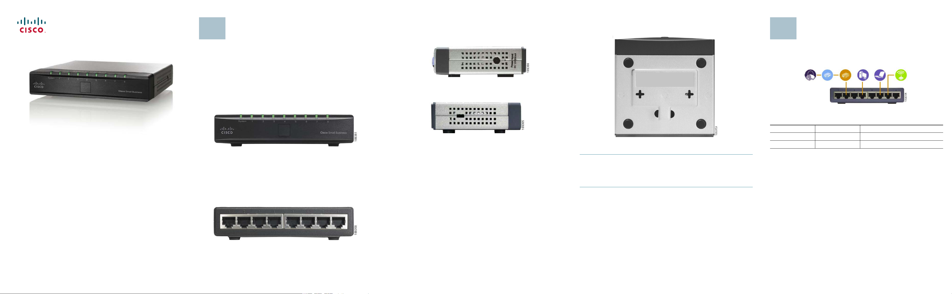
Product Overview
Side Panels
The power port is located on the side panel of the Switch.
The power port is where you will connect the power adapter.
Placement Options
Set the Switch on its four rubber feet, or mount the Switch on a wall.
Typical Installation Scenario
Cisco Small Business
Model SD208
8-Port 10/100 Switch
Thank you for choosing the Cisco 8-Port 10/100 Switch. The Switch provides
non-blocking, wire speed switching for your 10 and 100 Mbps network clients.
It's the perfect way of integrating 10Mbps Ethernet and 100Mbps Fast Ethernet
devices, to o. All ports are auto spe ed ne gotiating, and have automatic MDI/MDIX crossover detection, so you don’t have to worry about the cable type. Each
port independently negotiates for best speed and half- or full-duplex mode, for
up to 200Mbps of bandwidth per port. Fast store-and-forward switching
prevents damaged packets from being passed on into the network.
Front Panel
The LEDs are located on the front panel of the Switch.
System—(Green) This LED lights up and remains lit when the Switch is
powered on.
1-8—(Green) Each LED lights up when a connection is made through its
corresponding port. It flashes when the corresponding port is active.
The security slot is located on the opposite side of the Switch.
The security slot is where you can attach a lock to protect the Switch from theft.
To use the wall-mount option, follow these instructions:
STEP 1 The wall-mount slots are two crisscross slots on the Switch’s
bottom panel. Attach two screws to the wall, so that the Switch’s
wall-mount slots line up with the two screws.
S
TEP 2 Maneuver the Switch to insert the screws into the two slots.
The application diagram shown here is an example of a typical network
configuration.
When you connect your network devices, make sure you don’t exceed the
maximum cabling distances, which are listed in the following table:
From To Maximum Distance
Switch Switch or Hub 100 meters (328 feet)
Switch or Hub Computer 100 meters (328 feet)
Package Contents
• SD208 Switch
• Power Adapter
• Quick Start Guide
Back Panel
The Ethernet network ports are located on the back panel of the Switch.
1-8—These ports connect the Switch to network devices, such as computers.
Page 2
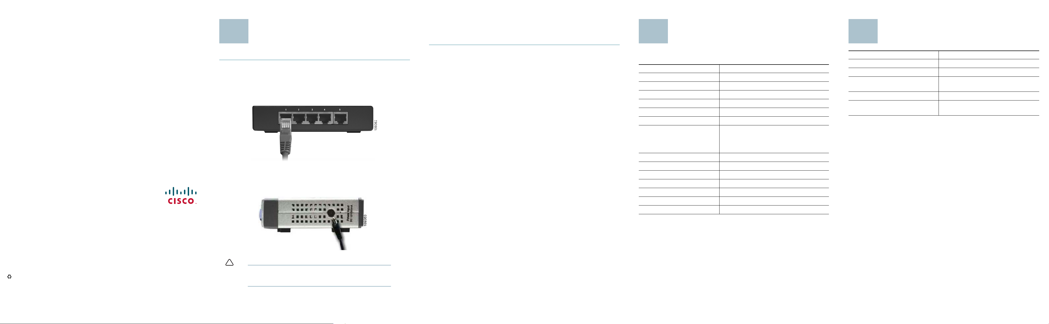
Installation
!
3
4
5
STEP 5 Power on the devices connected to the Switch. Each active port’s
corresponding LED will light up on the Switch.
Congratulations! The installation of the 10/100 Switch is complete!
Specifications
Where to Go From Here
Americas Headquarters
Cisco Systems, Inc.
170 West Tasman Drive
San Jose, CA 95134-1706
USA
http://www.cisco.com
Tel: 408 526-4000
800 553-NETS (6387)
Fax: 408 527-0883
Perform the steps in this section to install the hardware.
STEP 1 Make sure all of the devices you will connect to the Switch are
powered off.
TEP 2 Connect a Category 5 Ethernet network cable to one of the numbered
S
ports on the Switch. Connect the other end to a computer or other
network device.
S
TEP 3 Repeat step 2 to connect additional devices.
S
TEP 4 Connect the supplied power adapter to the power port on the Switch’s
side panel. Plug the other end of the adapter into an electrical outlet.
The following table lists the specifications for the SD208 10/100 Ethernet
Switch.
Item Specification
Model SD208
Standards IEEE 802.3, IEEE 802.3u
Ports 8 RJ-45 10/100 Mbps ports
Cabling Type Cat5 Ethernet
LEDs System, Port Status 1 through 8
Security Feature Security Slot
Dimensions WxHxD
5.12" x 1.18" x 5.00"
130 x 30 x 127 mm
Unit Weight 15 Ounces (0.43 kg)
Power DC12V/500mA
Certification FCC Class B, CE
Operating Temperature 32 to 122ºF (0 to 50ºC)
Storage Temperature -40 to 158ºF (-40 to 75ºC)
Operating Humidity 20 to 95%, noncondensing
Storage Humidity 5 to 90%, noncondensing
Resource Location
Customer Support www.cisco.com/go/smallbiz
End User License Agreement www.cisco.com/go/smallbiz
Regulatory Compliance and Safety
Information
Warranty Information www.cisco.com/go/smallbiz
Cisco Partner Central site for Small
Business
www.cisco.com/go/smallbiz
http://www.cisco.com/web/partners/
sell/smb/
Cisco, Cisco Systems, the Cisco logo, and the Cisco Systems logo are registered trademarks or
trademarks of Cisco Systems, Inc. and/or its affiliates in the United States and certain other
countries. All other trademarks mentioned in this document or Website are the property of their
respective owners. The use of the word partner does not imply a partnership relationship
between Cisco and any other company. (0705R)
© 2008 Cisco Systems, Inc. All rights reserved.
Printed in the USA on recycled paper containing 10% postconsumer waste.
78-18819-01
CAUTION Make sure you use the power adapter included with the
Switch. Using a different power adapter may damage the
Switch.
 Loading...