

Page 1

Cisco Wireless LAN Controller
Configuration Guide
Software Release 4.0
January 2007
Corporate Headquarters
Cisco Systems, Inc.
170 West Tasman Drive
San Jose, CA 95134-1706
USA
http://www.cisco.com
Tel: 408 526-4000
800 553-NETS (6387)
Fax: 408 526-4100
Text Part Number: OL-9141-03
Page 2

THE SPECIFICATIONS AND INFORMATION REGARDING THE PRODUCTS IN THIS MANUAL ARE SUBJECT TO CHANGE WITHOUT NOTICE. ALL
STATEMENTS, INFORMATION, AND RECOMMENDATIONS IN THIS MANUAL ARE BELIEVED TO BE ACCURATE BUT ARE PRESENTED WITHOUT
WARRANTY OF ANY KIND, EXPRESS OR IMPLIED. USERS MUST TAKE FULL RESPONSIBILITY FOR THEIR APPLICATION OF ANY PRODUCTS.
THE SOFTWARE LICENSE AND LIMITED WARRANTY FOR THE ACCOMPANYING PRODUCT ARE SET FORTH IN THE INFORMATION PACKET THAT
SHIPPED WITH THE PRODUCT AND ARE INCORPORATED HEREIN BY THIS REFERENCE. IF YOU ARE UNABLE TO LOCATE THE SOFTWARE LICENSE
OR LIMITED WARRANTY, CONTACT YOUR CISCO REPRESENTATIVE FOR A COPY.
The Cisco implementation of TCP header compression is an adaptation of a program developed by the University of California, Berkeley (UCB) as part of UCB’s public
domain version of the UNIX operating system. All rights reserved. Copyright © 1981, Regents of the University of California.
NOTWITHSTANDING ANY OTHER WARRANTY HEREIN, ALL DOCUMENT FILES AND SOFTWARE OF THESE SUPPLIERS ARE PROVIDED “AS IS” WITH
ALL FAULTS. CISCO AND THE ABOVE-NAMED SUPPLIERS DISCLAIM ALL WARRANTIES, EXPRESSED OR IMPLIED, INCLUDING, WITHOUT
LIMITATION, THOSE OF MERCHANTABILITY, FITNESS FOR A PARTICULAR PURPOSE AND NONINFRINGEMENT OR ARISING FROM A COURSE OF
DEALING, USAGE, OR TRADE PRACTICE.
IN NO EVENT SHALL CISCO OR ITS SUPPLIERS BE LIABLE FOR ANY INDIRECT, SPECIAL, CONSEQUENTIAL, OR INCIDENTAL DAMAGES, INCLUDING,
WITHOUT LIMITATION, LOST PROFITS OR LOSS OR DAMAGE TO DATA ARISING OUT OF THE USE OR INABILITY TO USE THIS MANUAL, EVEN IF CISCO
OR ITS SUPPLIERS HAVE BEEN ADVISED OF THE POSSIBILITY OF SUCH DAMAGES.
CCSP, CCVP, the Cisco Square Bridge logo, Follow Me Browsing, and StackWise are trademarks of Cisco Systems, Inc.; Changing the Way We Work, Live, Play, and Learn,
and iQuick Study are service marks of Cisco Systems, Inc.; and Access Registrar, Aironet, BPX, Catalyst, CCDA, CCDP, CCIE, CCIP, CCNA, CCNP, Cisco, the Cisco
Certified Internetwork Expert logo, Cisco IOS, Cisco Press, Cisco Systems, Cisco Systems Capital, the Cisco Systems logo, Cisco Unity, Enterprise/Solver, EtherChannel,
EtherFast, EtherSwitch, Fast Step, FormShare, GigaDrive, GigaStack, HomeLink, Internet Quotient, IOS, IP/TV, iQ Expertise, the iQ logo, iQ Net Readiness Scorecard,
LightStream, Linksys, MeetingPlace, MGX, the Networkers logo, Networking Academy, Network Registrar, Packet, PIX, Post-Routing, Pre-Routing, ProConnect,
RateMUX, ScriptShare, SlideCast, SMARTnet, The Fastest Way to Increase Your Internet Quotient, and TransPath are registered trademarks of Cisco Systems, Inc. and/or
its affiliates in the United States and certain other countries.
All other trademarks mentioned in this document or Website are the property of their respective owners. The use of the word partner does not imply a partnership relationship
between Cisco and any other company. (0601R)
Any Internet Protocol (IP) addresses used in this document are not intended to be actual addresses. Any examples, command display output, and figures included in the
document are shown for illustrative purposes only. Any use of actual IP addresses in illustrative content is unintentional and coincidental.
Cisco Wireless LAN Controller Configuration Guide
Copyright © 2007 Cisco Systems, Inc.
All rights reserved.
Page 3

Preface 17
Audience 18
Purpose 18
Organization 18
Conventions 19
Related Publications 21
Obtaining Documentation 22
Cisco.com 22
Product Documentation DVD 22
Ordering Documentation 22
Documentation Feedback 22
CONTENTS
CHAPTER
Cisco Product Security Overview 23
Reporting Security Problems in Cisco Products 23
Obtaining Technical Assistance 24
Cisco Technical Support & Documentation Website 25
Submitting a Service Request 25
Definitions of Service Request Severity 26
Obtaining Additional Publications and Information 26
1 Overview 1
Cisco Unified Wireless Network Solution Overview 2
Single-Controller Deployments 3
Multiple-Controller Deployments 4
Operating System Software 5
Operating System Security 6
Cisco WLAN Solution Wired Security 6
Layer 2 and Layer 3 LWAPP Operation 7
Operational Requirements 7
Configuration Requirements 7
Cisco Wireless LAN Controllers 7
Primary, Secondary, and Tertiary Controllers 8
Client Location 8
Controller Platforms 9
OL-9141-03
Cisco Wireless LAN Controller Configuration Guide
3
Page 4

Contents
Cisco 2000 and 2100 Series Controllers 9
Features Not Supported 9
Cisco 4400 Series Controllers 10
Catalyst 6500 Series Wireless Services Module 10
Cisco 28/37/38xx Series Integrated Services Router 11
Catalyst 3750G Integrated Wireless LAN Controller Switch 11
Cisco UWN Solution Wired Connections 11
Cisco UWN Solution WLANs 12
Identity Networking 12
Enhanced Integration with Cisco Secure ACS 13
File Transfers 14
Power over Ethernet 14
Pico Cell Functionality 14
Startup Wizard 15
Cisco Wireless LAN Controller Memory 16
Cisco Wireless LAN Controller Failover Protection 16
Network Connections to Cisco Wireless LAN Controllers 17
Cisco 2000 and 2100 Series Wireless LAN Controllers 17
Cisco 4400 Series Wireless LAN Controllers 18
CHAPTER
Rogue Access Points 19
Rogue Access Point Location, Tagging, and Containment 19
2 Using the Web-Browser and CLI Interfaces 1
Using the Web-Browser Interface 2
Guidelines for Using the GUI 2
Opening the GUI 2
Enabling Web and Secure Web Modes 3
Configuring the GUI for HTTPS 3
Loading an Externally Generated HTTPS Certificate 4
Disabling the GUI 5
Using Online Help 5
Using the CLI 5
Logging into the CLI 7
Using a Local Serial Connection 7
Using a Remote Ethernet Connection 7
Logging Out of the CLI 8
Navigating the CLI 8
Cisco Wireless LAN Controller Configuration Guide
4
OL-9141-03
Page 5

Enabling Wireless Connections to the Web-Browser and
CLI Interfaces
9
Contents
CHAPTER
3 Configuring Ports and Interfaces 1
Overview of Ports and Interfaces 2
Ports 2
Distribution System Ports 3
Service Port 5
Interfaces 5
Management Interface 6
AP-Manager Interface 6
Virtual Interface 7
Service-Port Interface 8
Dynamic Interface 8
WLANs 8
Configuring the Management, AP-Manager, Virtual, and Service-Port Interfaces 10
Using the GUI to Configure the Management, AP-Manager, Virtual, and Service-Port Interfaces 10
Using the CLI to Configure the Management, AP-Manager, Virtual, and Service-Port Interfaces 12
Using the CLI to Configure the Management Interface 12
Using the CLI to Configure the AP-Manager Interface 13
Using the CLI to Configure the Virtual Interface 14
Using the CLI to Configure the Service-Port Interface 15
Configuring Dynamic Interfaces 15
Using the GUI to Configure Dynamic Interfaces 15
Using the CLI to Configure Dynamic Interfaces 17
Configuring Ports 19
Configuring Port Mirroring 22
Configuring Spanning Tree Protocol 23
Using the GUI to Configure Spanning Tree Protocol 24
Using the CLI to Configure Spanning Tree Protocol 28
Enabling Link Aggregation 29
Link Aggregation Guidelines 33
Using the GUI to Enable Link Aggregation 34
Using the CLI to Enable Link Aggregation 35
Verifying LAG Settings Using the CLI 35
Configuring Neighbor Devices to Support LAG 35
Configuring a 4400 Series Controller to Support More Than 48 Access Points 36
Using Link Aggregation 36
Using Multiple AP-Manager Interfaces 36
OL-9141-03
Cisco Wireless LAN Controller Configuration Guide
5
Page 6

Contents
Connecting Additional Ports 41
CHAPTER
4 Configuring Controller SettingsWireless Device Access 1
Using the Configuration Wizard 2
Before You Start 2
Resetting the Device to Default Settings 3
Resetting to Default Settings Using the CLI 3
Resetting to Default Settings Using the GUI 3
Running the Configuration Wizard on the CLI 4
Managing the System Time and Date 5
Configuring the Time and Date Manually 5
Configuring an NTP Server 5
Configuring a Country Code 6
Enabling and Disabling 802.11 Bands 7
Configuring Administrator Usernames and Passwords 7
Configuring RADIUS Settings 8
Configuring SNMP 8
Changing the Default Values of SNMP Community Strings 9
Using the GUI to Change the SNMP Community String Default Values 9
Using the CLI to Change the SNMP Community String Default Values 11
Changing the Default Values for SNMP v3 Users 11
Using the GUI to Change the SNMP v3 User Default Values 12
Using the CLI to Change the SNMP v3 User Default Values 13
Enabling 802.3x Flow Control 13
Enabling System Logging 13
Using the GUI to Enable System Logging 13
Using the CLI to Enable System Logging 15
Enabling Dynamic Transmit Power Control 16
Configuring Multicast Mode 16
Understanding Multicast Mode 16
Guidelines for Using Multicast Mode 16
Enabling Multicast Mode 17
Configuring Client Roaming 17
Intra-Controller Roaming 18
Inter-Controller Roaming 18
Inter-Subnet Roaming 18
Voice-over-IP Telephone Roaming 18
CCX Layer 2 Client Roaming 19
Cisco Wireless LAN Controller Configuration Guide
6
OL-9141-03
Page 7

Using the GUI to Configure CCX Client Roaming Parameters 20
Using the CLI to Configure CCX Client Roaming Parameters 21
Configuring Voice and Video Parameters 22
Call Admission Control 22
U-APSD 23
Traffic Stream Metrics 23
Using the GUI to Configure Voice Parameters 23
Using the GUI to Configure Video Parameters 25
Using the GUI to View Voice and Video Settings 26
Using the CLI to Configure Voice Parameters 30
Using the CLI to Configure Video Parameters 31
Using the CLI to View Voice and Video Settings 32
Configuring the Supervisor 720 to Support the WiSM 34
General WiSM Guidelines 34
Configuring the Supervisor 35
Contents
CHAPTER
Using the Wireless LAN Controller Network Module 35
5 Configuring Security Solutions 1
Cisco UWN Solution Security 2
Security Overview 2
Layer 1 Solutions 2
Layer 2 Solutions 2
Layer 3 Solutions 3
Rogue Access Point Solutions 3
Rogue Access Point Challenges 3
Tagging and Containing Rogue Access Points 3
Integrated Security Solutions 4
Configuring the System for SpectraLink NetLink Telephones 4
Using the GUI to Enable Long Preambles 4
Using the CLI to Enable Long Preambles 5
Using the CLI to Configure Enhanced Distributed Channel Access 6
Using Management over Wireless 6
Using the GUI to Enable Management over Wireless 6
Using the CLI to Enable Management over Wireless 7
Configuring DHCP Option 82 7
Configuring Access Control Lists 8
Using the GUI to Configure Access Control Lists 9
Using the CLI to Configure Access Control Lists 12
Configuring Management Frame Protection 13
OL-9141-03
Cisco Wireless LAN Controller Configuration Guide
7
Page 8

Contents
Using the GUI to Configure MFP 14
Using the GUI to View MFP Settings 15
Using the CLI to Configure MFP 17
Using the CLI to View MFP Settings 18
Configuring Identity Networking 20
Identity Networking Overview 21
RADIUS Attributes Used in Identity Networking 22
QoS-Level 22
ACL-Name 22
Interface-Name 23
VLAN-Tag 23
Tunnel Attributes 24
Configuring AAA Override 25
Using the GUI to Configure AAA Override 25
Using the CLI to Configure AAA Override 26
CHAPTER
Configuring IDS 26
Configuring IDS Sensors 26
Using the GUI to Configure IDS Sensors 26
Using the CLI to Configure IDS Sensors 28
Viewing Shunned Clients 29
Configuring IDS Signatures 30
Using the GUI to Configure IDS Signatures 31
Using the CLI to Configure IDS Signatures 37
Using the CLI to View IDS Signature Events 38
Configuring AES Key Wrap 39
Using the GUI to Configure AES Key Wrap 39
Using the CLI to Configure AES Key Wrap 40
Configuring Maximum Local Database Entries 41
Using the GUI to Specify the Maximum Number of Local Database Entries 41
Using the CLI to Specify the Maximum Number of Local Database Entries 41
6 Configuring WLANsWireless Device Access 1
WLAN Overview 2
Configuring WLANs 2
Displaying, Creating, Disabling, and Deleting WLANs 2
Activating WLANs 3
Configuring DHCP 3
Internal DHCP Server 3
External DHCP Servers 4
Cisco Wireless LAN Controller Configuration Guide
8
OL-9141-03
Page 9

Using the GUI to Configure DHCP 5
Using the CLI to Configure DHCP 5
Configuring MAC Filtering for WLANs 6
Enabling MAC Filtering 6
Creating a Local MAC Filter 6
Configuring a Timeout for Disabled Clients 6
Assigning WLANs to VLANs 6
Configuring Layer 2 Security 7
Static WEP Keys 7
Dynamic 802.1X Keys and Authorization 7
Configuring a WLAN for Both Static and Dynamic WEP 8
WPA1 and WPA2 8
CKIP 12
Configuring Layer 3 Security 14
VPN Passthrough 15
Web-Based Authentication 16
Local Netuser 16
Configuring 802.3 Bridging 17
Configuring Quality of Service 17
Configuring QoS Enhanced BSS (QBSS) 18
Configuring Quality of Service Profiles 19
Configuring Cisco Client Extensions 22
Using the GUI to Configure CCX Aironet IEs 22
Using the GUI to View a Client’s CCX Version 24
Using the CLI to Configure CCX Aironet IEs 24
Using the CLI to View a Client’s CCX Version 25
Enabling WLAN Override 25
Using the GUI to Enable WLAN Override 25
Using the CLI to Enable WLAN Override 25
Configuring Access Point Groups 26
Creating Access Point Groups 27
Assigning Access Points to Access Point Groups 29
Configuring Multiple WLANs with the Same SSID 30
Additions to the Controller GUI 30
Addition to the Controller CLI 31
Configuring Conditional Web Redirect with 802.1X Authentication 32
Configuring the RADIUS Server 32
Using the GUI to Configure Conditional Web Redirect 34
Using the CLI to Configure Conditional Web Redirect 34
Disabling Accounting Servers per WLAN 35
Contents
OL-9141-03
Cisco Wireless LAN Controller Configuration Guide
9
Page 10

Contents
CHAPTER
7 Controlling Lightweight Access Points 1
The Controller Discovery Process 2
Verifying that Access Points Join the Controller 3
Verifying that Access Points Join the Controller Using the GUI 3
Verifying that Access Points Join the Controller Using the CLI 3
Cisco 1000 Series Lightweight Access Points 4
Cisco 1030 Remote Edge Lightweight Access Points 5
Cisco 1000 Series Lightweight Access Point Models 6
Cisco 1000 Series Lightweight Access Point External and Internal Antennas 6
External Antenna Connectors 6
Antenna Sectorization 7
Cisco 1000 Series Lightweight Access Point LEDs 7
Cisco 1000 Series Lightweight Access Point Connectors 7
Cisco 1000 Series Lightweight Access Point Power Requirements 8
Cisco 1000 Series Lightweight Access Point External Power Supply 8
Cisco 1000 Series Lightweight Access Point Mounting Options 8
Cisco 1000 Series Lightweight Access Point Physical Security 9
Cisco 1000 Series Lightweight Access Point Monitor Mode 9
Cisco Aironet 1510 Series Lightweight Outdoor Mesh Access Points 9
Wireless Mesh 10
Configuring and Deploying the AP1510 11
Adding the MAC Address of the Access Point to the Controller Filter List 12
Configuring Mesh Parameters 14
Configuring the Mesh Security Timer 16
Configuring Bridging Parameters 16
Autonomous Access Points Converted to Lightweight Mode 19
Guidelines for Using Access Points Converted to Lightweight Mode 20
Reverting from Lightweight Mode to Autonomous Mode 20
Using a Controller to Return to a Previous Release 20
Using the MODE Button and a TFTP Server to Return to a Previous Release 21
Access Point Authorization 21
Controllers Accept SSCs from Access Points Converted to Lightweight Mode 21
Using DHCP Option 43 22
Using a Controller to Send Debug Commands to Access Points Converted to Lightweight Mode 22
Converted Access Points Send Crash Information to Controller 22
Converted Access Points Send Radio Core Dumps to Controller 23
Enabling Memory Core Dumps from Converted Access Points 23
Display of MAC Addresses for Converted Access Points 23
Disabling the Reset Button on Access Points Converted to Lightweight Mode 24
Cisco Wireless LAN Controller Configuration Guide
10
OL-9141-03
Page 11

Configuring a Static IP Address on an Access Point Converted to Lightweight Mode 24
Dynamic Frequency Selection 24
Retrieving the Unique Device Identifier on Controllers and Access Points 25
Using the GUI to Retrieve the Unique Device Identifier on Controllers and Access Points 26
Using the CLI to Retrieve the Unique Device Identifier on Controllers and Access Points 27
Performing a Link Test 27
Using the GUI to Perform a Link Test 29
Using the CLI to Perform a Link Test 30
Configuring Cisco Discovery Protocol 31
Configuring Power over Ethernet 33
Using the GUI to Configure Power over Ethernet 33
Using the CLI to Configure Power over Ethernet 35
Configuring Flashing LEDs 36
Authorizing Access Points Using MICs 36
Contents
CHAPTER
CHAPTER
8 Managing Controller Software and Configurations 1
Transferring Files to and from a Controller 2
Upgrading Controller Software 2
Updating Controller Software 3
Saving Configurations 4
Clearing the Controller Configuration 5
Erasing the Controller Configuration 5
Resetting the Controller 5
9 Managing User Accounts 1
Creating Guest User Accounts 2
Creating a Lobby Ambassador Account 2
Using the GUI to Create a Lobby Ambassador Account 2
Using the CLI to Create a Lobby Ambassador Account 4
Creating Guest User Accounts as a Lobby Ambassador 4
Viewing Guest User Accounts 6
Using the GUI to View Guest Accounts 6
Using the CLI to View Guest Accounts 7
Web Authentication Process 7
Choosing the Web Authentication Login Window 9
Choosing the Default Web Authentication Login Window 9
Using the GUI to Choose the Default Web Authentication Login Window 9
Using the CLI to Choose the Default Web Authentication Login Window 10
OL-9141-03
Cisco Wireless LAN Controller Configuration Guide
11
Page 12

Contents
Modified Default Web Authentication Login Window Example 12
Using a Customized Web Authentication Login Window from an External Web Server 13
Using the GUI to Choose a Customized Web Authentication Login Window from an External Web
Server
Using the CLI to Choose a Customized Web Authentication Login Window from an External Web
Server
Downloading a Customized Web Authentication Login Window 14
Using the GUI to Download a Customized Web Authentication Login Window 15
Using the CLI to Download a Customized Web Authentication Login Window 16
Customized Web Authentication Login Window Example 17
Using the CLI to Verify the Web Authentication Login Window Settings 17
13
14
CHAPTER
10 Configuring Radio Resource ManagementWireless Device Access 1
Overview of Radio Resource Management 2
Radio Resource Monitoring 2
Dynamic Channel Assignment 3
Dynamic Transmit Power Control 4
Coverage Hole Detection and Correction 4
Client and Network Load Balancing 4
RRM Benefits 5
Overview of RF Groups 5
RF Group Leader 5
RF Group Name 6
Configuring an RF Group 6
Using the GUI to Configure an RF Group 7
Using the CLI to Configure RF Groups 8
Viewing RF Group Status 8
Using the GUI to View RF Group Status 8
Using the CLI to View RF Group Status 11
Enabling Rogue Access Point Detection 12
Using the GUI to Enable Rogue Access Point Detection 12
Using the CLI to Enable Rogue Access Point Detection 14
Configuring Dynamic RRM 15
Using the GUI to Configure Dynamic RRM 15
Using the CLI to Configure Dynamic RRM 22
Overriding Dynamic RRM 23
Statically Assigning Channel and Transmit Power Settings to Access Point Radios 24
Using the GUI to Statically Assign Channel and Transmit Power Settings 24
Using the CLI to Statically Assign Channel and Transmit Power Settings 26
Cisco Wireless LAN Controller Configuration Guide
12
OL-9141-03
Page 13

Disabling Dynamic Channel and Power Assignment Globally for a Controller 27
Using the GUI to Disable Dynamic Channel and Power Assignment 27
Using the CLI to Disable Dynamic Channel and Power Assignment 27
Viewing Additional RRM Settings Using the CLI 28
Configuring CCX Radio Management Features 29
Broadcast Location Measurement Requests 29
Location Calibration 29
Using the GUI to Configure CCX Radio Management 30
Using the CLI to Configure CCX Radio Management 31
Using the CLI to Obtain CCX Radio Management Information 32
Contents
CHAPTER
CHAPTER
11 Configuring Mobility GroupsWireless Device Access 1
Overview of Mobility 2
Overview of Mobility Groups 5
Determining When to Include Controllers in a Mobility Group 7
Configuring Mobility Groups 7
Prerequisites 7
Using the GUI to Configure Mobility Groups 8
Using the CLI to Configure Mobility Groups 11
Configuring Auto-Anchor Mobility 11
Guidelines for Using Auto-Anchor Mobility 12
Using the GUI to Configure Auto-Anchor Mobility 13
Using the CLI to Configure Auto-Anchor Mobility 14
Running Mobility Ping Tests 15
12 Configuring Hybrid REAPWireless Device Access 1
Overview of Hybrid REAP 2
Hybrid-REAP Authentication Process 2
Hybrid REAP Guidelines 4
Configuring Hybrid REAP 5
Configuring the Switch at the Remote Site 5
Configuring the Controller for Hybrid REAP 6
Using the GUI to Configure the Controller for Hybrid REAP 6
Using the CLI to Configure the Controller for Hybrid REAP 12
Configuring an Access Point for Hybrid REAP 12
Using the GUI to Configure an Access Point for Hybrid REAP 12
Using the CLI to Configure an Access Point for Hybrid REAP 15
Connecting Client Devices to the WLANs 16
OL-9141-03
Cisco Wireless LAN Controller Configuration Guide
13
Page 14

Contents
APPENDIX
APPENDIX
A Safety Considerations and
Translated Safety Warnings
1
Safety Considerations 2
Warning Definition 2
Class 1 Laser Product Warning 5
Ground Conductor Warning 7
Chassis Warning for Rack-Mounting and Servicing 9
Battery Handling Warning for 4400 Series Controllers 18
Equipment Installation Warning 20
More Than One Power Supply Warning for 4400 Series Controllers 23
B Declarations of Conformity and Regulatory Information 1
Regulatory Information for 1000 Series Access Points 2
Manufacturers Federal Communication Commission Declaration of Conformity Statement 2
Department of Communications—Canada 3
Canadian Compliance Statement 3
European Community, Switzerland, Norway, Iceland, and Liechtenstein 4
Declaration of Conformity with Regard to the R&TTE Directive 1999/5/EC 4
Declaration of Conformity for RF Exposure 5
Guidelines for Operating Cisco Aironet Access Points in Japan 6
Administrative Rules for Cisco Aironet Access Points in Taiwan 7
Access Points with IEEE 802.11a Radios 7
All Access Points 7
Declaration of Conformity Statements 8
FCC Statement for Cisco 2000 Series Wireless LAN Controllers 8
FCC Statement for Cisco 4400 Series Wireless LAN Controllers 9
APPENDIX
C End User License and Warranty 1
End User License Agreement 2
Limited Warranty 4
Disclaimer of Warranty 6
General Terms Applicable to the Limited Warranty Statement and End User License Agreement 6
Additional Open Source Terms 7
APPENDIX
D System Messages and LED Patterns 1
System Messages 2
Interpreting LEDs 5
Cisco Wireless LAN Controller Configuration Guide
14
OL-9141-03
Page 15

Interpreting Controller LEDs 5
Interpreting Lightweight Access Point LEDs 5
Contents
APPENDIX
I
NDEX
E Logical Connectivity Diagrams 1
Cisco WiSM 3
Cisco 28/37/38xx Integrated Services Router 5
Catalyst 3750G Integrated Wireless LAN Controller Switch 6
OL-9141-03
Cisco Wireless LAN Controller Configuration Guide
15
Page 16

Contents
Cisco Wireless LAN Controller Configuration Guide
16
OL-9141-03
Page 17

Preface
This preface provides an overview of the Cisco Wireless LAN Controller Configuration Guide, Release
4.0, references related publications, and explains how to obtain other documentation and technical
assistance, if necessary. It contains these sections:
• Audience, page 18
• Purpose, page 18
• Organization, page 18
• Conventions, page 19
• Related Publications, page 21
• Obtaining Documentation and Submitting a Service Request, page 22
OL-9141-03
Cisco Wireless LAN Controller Configuration Guide
17
Page 18

Audience
Audience
This guide describes Cisco Wireless LAN Controllers and Cisco Lightweight Access Points. This guide
is for the networking professional who installs and manages these devices. To use this guide, you should
be familiar with the concepts and terminology of wireless LANs.
Purpose
This guide provides the information you need to set up and configure wireless LAN controllers.
Note This version of the Cisco Wireless LAN Controller Configuration Guide pertains specifically to
controller software release 4.0. If you are using an earlier version of software, you will notice differences
in features, functionality, and GUI pages.
Organization
Preface
This guide is organized into these chapters:
Chapter 1, “Overview,” provides an overview of the network roles and features of wireless LAN
controllers.
Chapter 2, “Using the Web-Browser and CLI Interfaces,” describes how to use the controller GUI and
CLI.
Chapter 3, “Configuring Ports and Interfaces,” describes the controller’s physical ports and interfaces
and provides instructions for configuring them.
Chapter 4, “Configuring Controller SettingsWireless Device Access,” describes how to configure
settings on the controllers.
Chapter 5, “Configuring Security Solutions,” describes application-specific solutions for wireless
LANs.
Chapter 6, “Configuring WLANsWireless Device Access,” describes how to configure wireless LANs
and SSIDs on your system.
Chapter 7, “Controlling Lightweight Access Points,” explains how to connect access points to the
controller and manage access point settings.
Chapter 8, “Managing Controller Software and Configurations,” describes how to upgrade and manage
controller software and configurations.
Chapter 9, “Managing User Accounts,” explains how to create and manage guest user accounts,
describes the web authentication process, and provides instructions for customizing the web
authentication login window.
Chapter 10, “Configuring Radio Resource ManagementWireless Device Access,” describes radio
resource management (RRM) and explains how to configure it on the controllers.
Chapter 11, “Configuring Mobility GroupsWireless Device Access,” describes mobility groups and
explains how to configure them on the controllers.
Chapter 12, “Configuring Hybrid REAPWireless Device Access,” describes hybrid REAP and explains
how to configure this feature on controllers and access points.
Cisco Wireless LAN Controller Configuration Guide
18
OL-9141-03
Page 19

Preface
Appendix A, “Safety Considerations and Translated Safety Warnings,” lists safety considerations and
translations of the safety warnings that apply to the Cisco Unified Wireless Network Solution products.
Appendix B, “Declarations of Conformity and Regulatory Information,” provides declarations of
conformity and regulatory information for the products in the Cisco Unified Wireless Network Solution.
Appendix C, “End User License and Warranty,” describes the end user license and warranty that apply
to the Cisco Unified Wireless Network Solution products.
Appendix D, “System Messages and LED Patterns,” lists system messages that can appear on the Cisco
Unified Wireless Network Solution interfaces and describes the LED patterns on controllers and
lightweight access points.
Appendix E, “Logical Connectivity Diagrams,”provides logical connectivity diagrams and related
software commands for controllers that are integrated into other Cisco products.
Conventions
This publication uses these conventions to convey instructions and information:
Command descriptions use these conventions:
Conventions
• Commands and keywords are in boldface text.
• Arguments for which you supply values are in italic.
• Square brackets ([ ]) mean optional elements.
• Braces ({ }) group required choices, and vertical bars ( | ) separate the alternative elements.
• Braces and vertical bars within square brackets ([{ | }]) mean a required choice within an optional
element.
Interactive examples use these conventions:
• Terminal sessions and system displays are in screen font.
• Information you enter is in boldface screen font.
• Nonprinting characters, such as passwords or tabs, are in angle brackets (< >).
Notes, cautions, and timesavers use these conventions and symbols:
Note Means reader take note. Notes contain helpful suggestions or references to materials not contained in
this manual.
Caution Means reader be careful. In this situation, you might do something that could result equipment damage
or loss of data.
OL-9141-03
Cisco Wireless LAN Controller Configuration Guide
19
Page 20

Conventions
Preface
Warning
Waarschuwing
Varoitus
Attention
Warnung
This warning symbol means danger. You are in a situation that could cause bodily injury. Before you
work on any equipment, be aware of the hazards involved with electrical circuitry and be familiar
with standard practices for preventing accidents. (To see translations of the warnings that appear
in this publication, refer to the appendix “Translated Safety Warnings.”)
Dit waarschuwingssymbool betekent gevaar. U verkeert in een situatie die lichamelijk letsel kan
veroorzaken. Voordat u aan enige apparatuur gaat werken, dient u zich bewust te zijn van de bij
elektrische schakelingen betrokken risico’s en dient u op de hoogte te zijn van standaard
maatregelen om ongelukken te voorkomen. (Voor vertalingen van de waarschuwingen die in deze
publicatie verschijnen, kunt u het aanhangsel “Translated Safety Warnings” (Vertalingen van
veiligheidsvoorschriften) raadplegen.)
Tämä varoitusmerkki merkitsee vaaraa. Olet tilanteessa, joka voi johtaa ruumiinvammaan. Ennen
kuin työskentelet minkään laitteiston parissa, ota selvää sähkökytkentöihin liittyvistä vaaroista ja
tavanomaisista onnettomuuksien ehkäisykeinoista. (Tässä julkaisussa esiintyvien varoitusten
käännökset löydät liitteestä "Translated Safety Warnings" (käännetyt turvallisuutta koskevat
varoitukset).)
Ce symbole d’avertissement indique un danger. Vous vous trouvez dans une situation pouvant
entraîner des blessures. Avant d’accéder à cet équipement, soyez conscient des dangers posés par
les circuits électriques et familiarisez-vous avec les procédures courantes de prévention des
accidents. Pour obtenir les traductions des mises en garde figurant dans cette publication, veuillez
consulter l’annexe intitulée « Translated Safety Warnings » (Traduction des avis de sécurité).
Dieses Warnsymbol bedeutet Gefahr. Sie befinden sich in einer Situation, die zu einer
Körperverletzung führen könnte. Bevor Sie mit der Arbeit an irgendeinem Gerät beginnen, seien Sie
sich der mit elektrischen Stromkreisen verbundenen Gefahren und der Standardpraktiken zur
Vermeidung von Unfällen bewußt. (Übersetzungen der in dieser Veröffentlichung enthaltenen
Warnhinweise finden Sie im Anhang mit dem Titel “Translated Safety Warnings” (Übersetzung der
Warnhinweise).)
20
Avvertenza
Questo simbolo di avvertenza indica un pericolo. Si è in una situazione che può causare infortuni.
Prima di lavorare su qualsiasi apparecchiatura, occorre conoscere i pericoli relativi ai circuiti
elettrici ed essere al corrente delle pratiche standard per la prevenzione di incidenti. La traduzione
delle avvertenze riportate in questa pubblicazione si trova nell’appendice, “Translated Safety
Warnings” (Traduzione delle avvertenze di sicurezza).
Advarsel
Dette varselsymbolet betyr fare. Du befinner deg i en situasjon som kan føre til personskade. Før du
utfører arbeid på utstyr, må du være oppmerksom på de faremomentene som elektriske kretser
innebærer, samt gjøre deg kjent med vanlig praksis når det gjelder å unngå ulykker. (Hvis du vil se
oversettelser av de advarslene som finnes i denne publikasjonen, kan du se i vedlegget "Translated
Safety Warnings" [Oversatte sikkerhetsadvarsler].)
Aviso
Este símbolo de aviso indica perigo. Encontra-se numa situação que lhe poderá causar danos
fisicos. Antes de começar a trabalhar com qualquer equipamento, familiarize-se com os perigos
relacionados com circuitos eléctricos, e com quaisquer práticas comuns que possam prevenir
possíveis acidentes. (Para ver as traduções dos avisos que constam desta publicação, consulte o
apêndice “Translated Safety Warnings” - “Traduções dos Avisos de Segurança”).
Cisco Wireless LAN Controller Configuration Guide
OL-9141-03
Page 21

Preface
Related Publications
¡Advertencia!
Este símbolo de aviso significa peligro. Existe riesgo para su integridad física. Antes de manipular
cualquier equipo, considerar los riesgos que entraña la corriente eléctrica y familiarizarse con los
procedimientos estándar de prevención de accidentes. (Para ver traducciones de las advertencias
que aparecen en esta publicación, consultar el apéndice titulado “Translated Safety Warnings.”)
Varning!
Denna varningssymbol signalerar fara. Du befinner dig i en situation som kan leda till personskada.
Innan du utför arbete på någon utrustning måste du vara medveten om farorna med elkretsar och
känna till vanligt förfarande för att förebygga skador. (Se förklaringar av de varningar som
förekommer i denna publikation i appendix "Translated Safety Warnings" [Översatta
säkerhetsvarningar].)
Related Publications
These documents provide complete information about the Cisco Unified Wireless Network Solution:
• Quick Start Guide: Cisco 2000 Series Wireless LAN Controllers
• Quick Start Guide: Cisco 4400 Series Wireless LAN Controllers
• Cisco Wireless LAN Controller Command Reference
• Cisco Wireless Control System Configuration Guide
• Quick Start Guide: Cisco Wireless Control System for Microsoft Windows
• Quick Start Guide: Cisco Wireless Control System for Linux
• Quick start guide and hardware installation guide for your specific lightweight access point
Click this link to browse to the Cisco Support and Documentation page:
http://www.cisco.com/cisco/web/support/index.html
• Cisco 1800 Series Routers Hardware Installation Guide
• Cisco AP HWIC Wireless Configuration Guide
• Cisco Router and Security Device Manager (SDM) Quick Start Guide
• Cisco Aironet 2.4-GHz Articulated Dipole Antenna (AIR-ANT4941)
• Cisco Aironet High Gain Omnidirectional Ceiling Mount Antenna (AIR-ANT1728)
• Mounting Instructions for the Cisco Aironet 6.5 dBi Diversity Patch Wall Mount Antenna
• Cisco Aironet 2 dBi Diversity Omnidirectional Ceiling Mount Antenna (AIR-ANT5959)
• Cisco Multiband 2.4/5GHz Articulated Dipole Antenna (AIR-ANT1841)
• Cisco Multiband 2.4/5G Diversity Omnidirectional Ceiling Mount Antenna (AIR-ANT1828)
• Cisco Multiband 2.4/5G Patch Wall Mount Antenna (AIR-ANT1859)
• Mounting Instructions for the Cisco Diversity Omnidirectional Ceiling Mount Antenna
• Mounting Instructions for the Cisco Patch Wall Mount Antenna
Related documents from the Cisco TAC Web pages include:
• Antenna Cabling
OL-9141-03
Cisco Wireless LAN Controller Configuration Guide
21
Page 22

Obtaining Documentation and Submitting a Service Request
Obtaining Documentation and Submitting a Service Request
For information on obtaining documentation, submitting a service request, and gathering additional
information, see the monthly What’s New in Cisco Product Documentation, which also lists all new and
revised Cisco technical documentation, at:
http://www.cisco.com/en/US/docs/general/whatsnew/whatsnew.html
Subscribe to the What’s New in Cisco Product Documentation as a Really Simple Syndication (RSS) feed
and set content to be delivered directly to your desktop using a reader application. The RSS feeds are a free
service and Cisco currently supports RSS Version 2.0.
Preface
Cisco Wireless LAN Controller Configuration Guide
22
OL-9141-03
Page 23

CHA P TER
Overview
This chapter describes the controller components and features. Its contains these sections:
• Cisco Unified Wireless Network Solution Overview, page 1-2
• Operating System Software, page 1-5
• Operating System Security, page 1-6
• Layer 2 and Layer 3 LWAPP Operation, page 1-7
• Cisco Wireless LAN Controllers, page 1-7
• Controller Platforms, page 1-9
• Cisco UWN Solution Wired Connections, page 1-11
• Cisco UWN Solution WLANs, page 1-12
• Identity Networking, page 1-12
• File Transfers, page 1-14
• Power over Ethernet, page 1-14
1
• Pico Cell Functionality, page 1-14
• Rogue Access Points, page 1-19
OL-9141-03
Cisco Wireless LAN Controller Configuration Guide
1-1
Page 24

Cisco Unified Wireless Network Solution Overview
Cisco Unified Wireless Network Solution Overview
The Cisco Unified Wireless Network (Cisco UWN) Solution is designed to provide 802.11 wireless
networking solutions for enterprises and service providers. The Cisco UWN Solution simplifies
deploying and managing large-scale wireless LANs and enables a unique best-in-class security
infrastructure. The operating system manages all data client, communications, and system
administration functions, performs radio resource management (RRM) functions, manages system-wide
mobility policies using the operating system security solution, and coordinates all security functions
using the operating system security framework.
The Cisco UWN Solution consists of Cisco Wireless LAN Controllers and their associated lightweight
access points controlled by the operating system, all concurrently managed by any or all of the operating
system user interfaces:
• An HTTP and/or HTTPS full-featured Web User Interface hosted by Cisco Wireless LAN
Controllers can be used to configure and monitor individual controllers. See Chapter 2.
• A full-featured command-line interface (CLI) can be used to configure and monitor individual Cisco
Wireless LAN Controllers. See Chapter 2.
• The Cisco Wireless Control System (WCS), which you use to configure and monitor one or more
Cisco Wireless LAN Controllers and associated access points. WCS has tools to facilitate
large-system monitoring and control. WCS runs on Windows 2000, Windows 2003, and Red Hat
Enterprise Linux ES servers.
Chapter 1 Overview
Note WCS software release 4.0 must be used with controllers running controller software release
4.0. Do not attempt to use older versions of WCS software with controllers running
controller software release 4.0.
• An industry-standard SNMP V1, V2c, and V3 interface can be used with any SNMP-compliant
third-party network management system.
The Cisco UWN Solution supports client data services, client monitoring and control, and all rogue
access point detection, monitoring, and containment functions. It uses lightweight access points, Cisco
Wireless LAN Controllers, and the optional Cisco WCS to provide wireless services to enterprises and
service providers.
Note Unless otherwise noted, all of the Cisco wireless LAN controllers are hereafter referred to as controllers,
and all of the Cisco lightweight access points are hereafter referred to as access points.
Cisco Wireless LAN Controller Configuration Guide
1-2
OL-9141-03
Page 25
Chapter 1 Overview
Cisco Unified Wireless Network Solution Overview
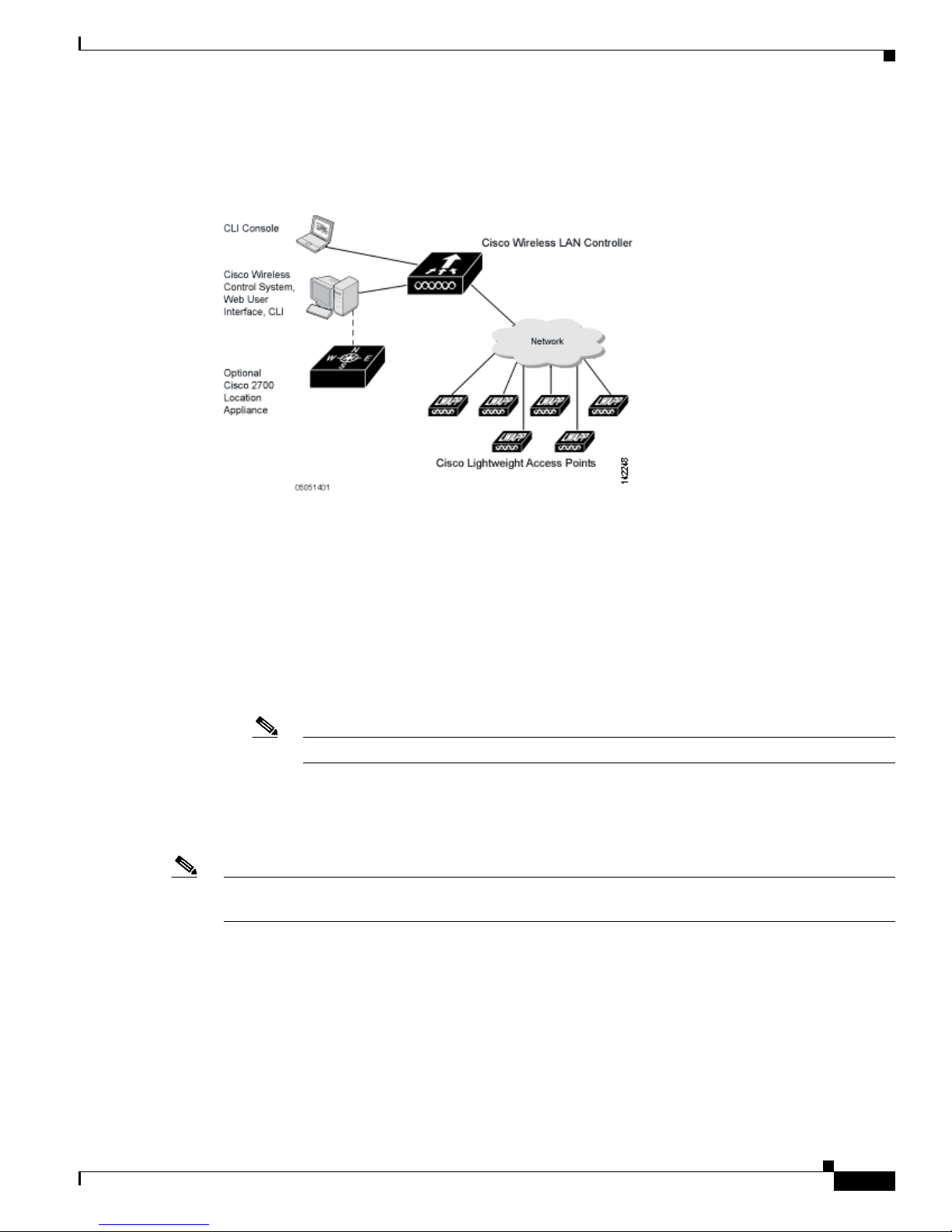
Figure 1-1 shows the Cisco Wireless LAN Solution components, which can be simultaneously deployed
across multiple floors and buildings.
Figure 1-1 Cisco UWN Solution Components
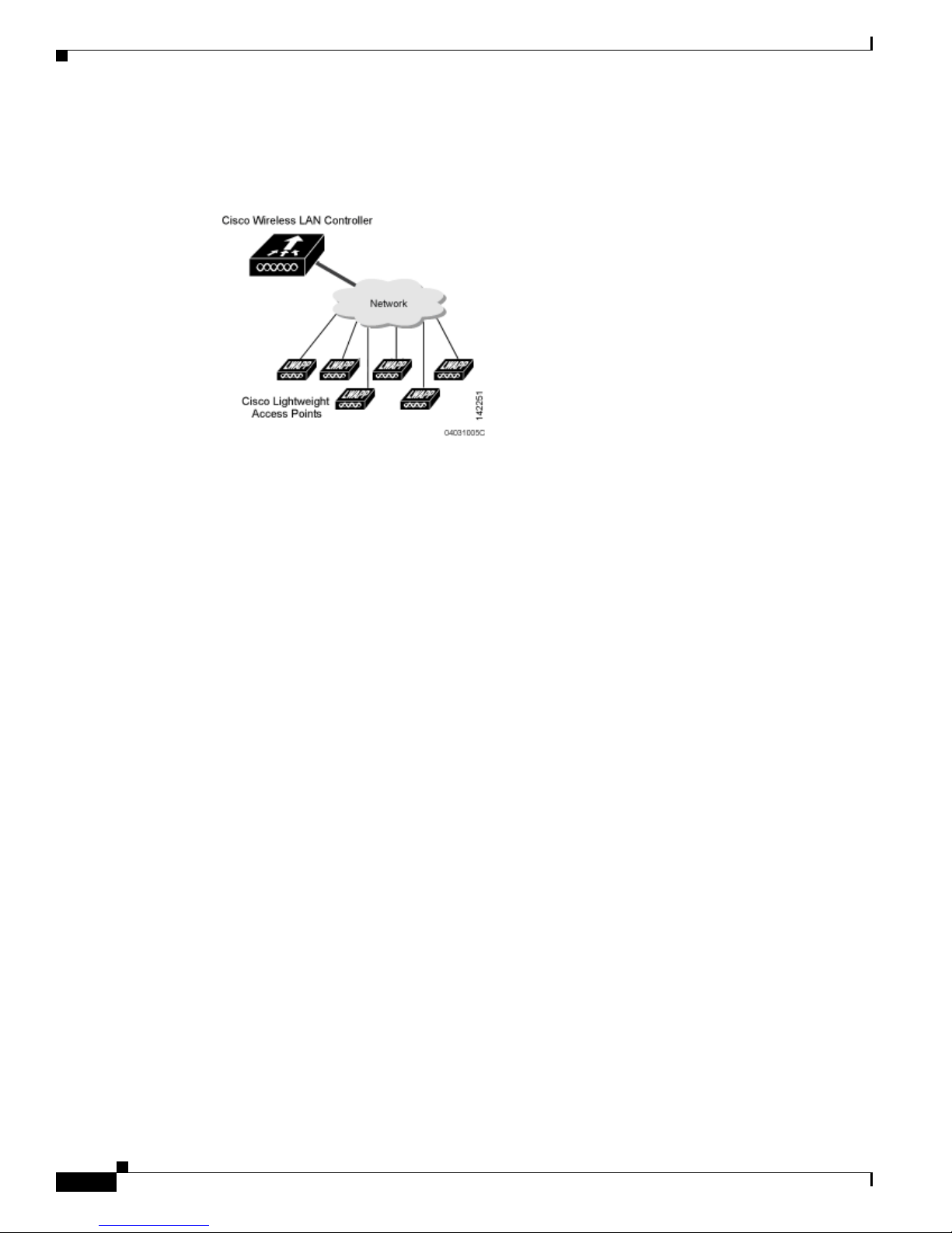
Single-Controller Deployments
A standalone controller can support lightweight access points across multiple floors and buildings
simultaneously, and supports the following features:
• Autodetecting and autoconfiguring lightweight access points as they are added to the network.
• Full control of lightweight access points.
• Full control of up to 16 wireless LAN (SSID) policies for Cisco 1000 series access points.
Note LWAPP-enabled access points support up to 8 wireless LAN (SSID) policies.
• Lightweight access points connect to controllers through the network. The network equipment may
or may not provide Power over Ethernet to the access points.
Note that some controllers use redundant Gigabit Ethernet connections to bypass single network failures.
Note Some controllers can connect through multiple physical ports to multiple subnets in the network. This
feature can be helpful when operators want to confine multiple VLANs to separate subnets.
OL-9141-03
Cisco Wireless LAN Controller Configuration Guide
1-3
Page 26
Cisco Unified Wireless Network Solution Overview
Figure 1-2 shows a typical single-controller deployment.
Figure 1-2 Single-Controller Deployment
Chapter 1 Overview
Multiple-Controller Deployments
Each controller can support lightweight access points across multiple floors and buildings
simultaneously. However, full functionality of the Cisco Wireless LAN Solution is realized when it
includes multiple controllers. A multiple-controller system has the following additional features:
• Autodetecting and autoconfiguring RF parameters as the controllers are added to the network.
• Same-Subnet (Layer 2) Roaming and Inter-Subnet (Layer 3) Roaming.
• Automatic access point failover to any redundant controller with a reduced access point load (refer
to the “Cisco Wireless LAN Controller Failover Protection” section on page 1-16).
Cisco Wireless LAN Controller Configuration Guide
1-4
OL-9141-03
Page 27
Chapter 1 Overview
Operating System Software
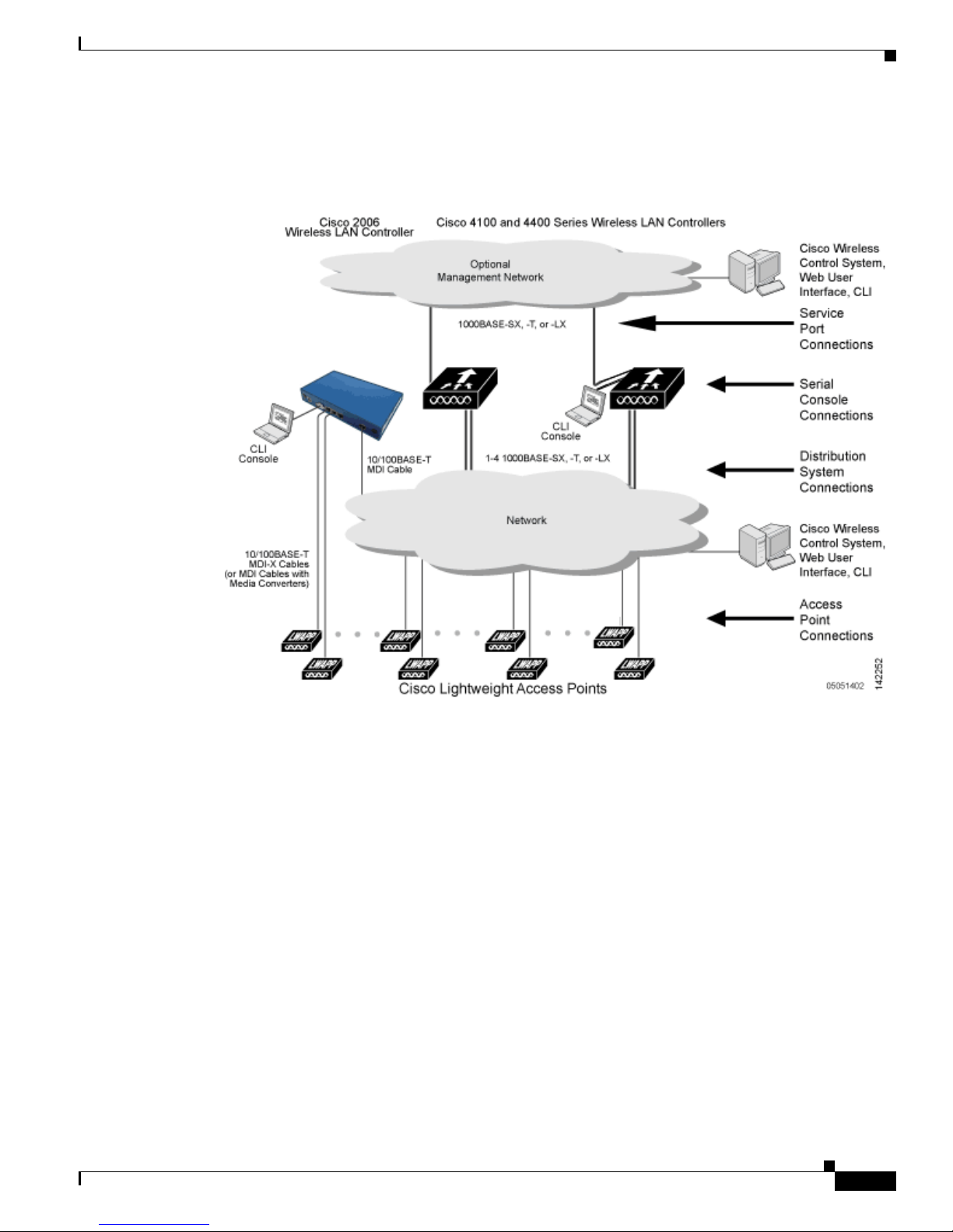
Figure 1-3 shows a typical multiple-controller deployment. The figure also shows an optional dedicated
Management Network and the three physical connection types between the network and the controllers.
Figure 1-3 Typical Multi-Controller Deployment
Operating System Software
The operating system software controls Cisco Wireless LAN Controllers and Cisco 1000 Series
Lightweight Access Points. It includes full operating system security and Radio Resource Management
(RRM) features.
OL-9141-03
Cisco Wireless LAN Controller Configuration Guide
1-5
Page 28

Operating System Security
Operating System Security
Operating system security bundles Layer 1, Layer 2, and Layer 3 security components into a simple,
Cisco WLAN Solution-wide policy manager that creates independent security policies for each of up to
16 wireless LANs. (Refer to the “Cisco UWN Solution WLANs” section on page 1-12.)
The 802.11 Static WEP weaknesses can be overcome using robust industry-standard security solutions,
such as:
• 802.1X dynamic keys with extensible authentication protocol (EAP).
• Wi-Fi protected access (WPA) dynamic keys. The Cisco WLAN Solution WPA implementation
includes:
–
Temporal key integrity protocol (TKIP) + message integrity code checksum (Michael) dynamic
keys, or
–
WEP keys, with or without Pre-Shared key Passphrase.
• RSN with or without Pre-Shared key.
• Cranite FIPS140-2 compliant passthrough.
• Fortress FIPS140-2 compliant passthrough.
Chapter 1 Overview
• Optional MAC Filtering.
The WEP problem can be further solved using industry-standard Layer 3 security solutions, such as:
• Passthrough VPNs
• The Cisco Wireless LAN Solution supports local and RADIUS MAC Address filtering.
• The Cisco Wireless LAN Solution supports local and RADIUS user/password authentication.
• The Cisco Wireless LAN Solution also uses manual and automated Disabling to block access to
network services. In manual Disabling, the operator blocks access using client MAC addresses. In
automated Disabling, which is always active, the operating system software automatically blocks
access to network services for an operator-defined period of time when a client fails to authenticate
for a fixed number of consecutive attempts. This can be used to deter brute-force login attacks.
These and other security features use industry-standard authorization and authentication methods to
ensure the highest possible security for your business-critical wireless LAN traffic.
Cisco WLAN Solution Wired Security
Many traditional access point vendors concentrate on security for the Wireless interface similar to that
described in the “Operating System Security” section on page 1-6. However, for secure Cisco Wireless
LAN Controller Service Interfaces, Cisco Wireless LAN Controller to access point, and inter-Cisco
Wireless LAN Controller communications during device servicing and client roaming, the operating
system includes built-in security.
Each Cisco Wireless LAN Controller and Cisco 1000 series lightweight access point is manufactured
with a unique, signed X.509 certificate. These signed certificates are used to verify downloaded code
before it is loaded, ensuring that hackers do not download malicious code into any Cisco Wireless LAN
Controller or Cisco 1000 series lightweight access point.
Cisco Wireless LAN Controller Configuration Guide
1-6
OL-9141-03
Page 29

Chapter 1 Overview
Layer 2 and Layer 3 LWAPP Operation
The LWAPP communications between Cisco Wireless LAN Controller and Cisco 1000 series
lightweight access points can be conducted at ISO Data Link Layer 2 or Network Layer 3.
Note The IPv4 network layer protocol is supported for transport through an LWAPP controller system. IPv6
(for clients only) and AppleTalk are also supported but only on 4400 series controllers and the Cisco
WiSM. Other Layer 3 protocols (such as IPX, DECnet Phase IV, OSI CLNP, and so on) and Layer 2
(bridged) protocols (such as LAT and NetBeui) are not supported.
Operational Requirements
The requirement for Layer 2 LWAPP communications is that the Cisco Wireless LAN Controller and
Cisco 1000 series lightweight access points must be connected to each other through Layer 2 devices on
the same subnet. This is the default operational mode for the Cisco Wireless LAN Solution. Note that
when the Cisco Wireless LAN Controller and Cisco 1000 series lightweight access points are on
different subnets, these devices must be operated in Layer 3 mode.
The requirement for Layer 3 LWAPP communications is that the Cisco Wireless LAN Controllers and
Cisco 1000 series lightweight access points can be connected through Layer 2 devices on the same
subnet, or connected through Layer 3 devices across subnets. Another requirement is that the IP
addresses of access points should be either statically assigned or dynamically assigned through an
external DHCP server.
Note that all Cisco Wireless LAN Controllers in a mobility group must use the same LWAPP Layer 2 or
Layer 3 mode, or you will defeat the Mobility software algorithm.
Layer 2 and Layer 3 LWAPP Operation
Configuration Requirements
When you are operating the Cisco Wireless LAN Solution in Layer 2 mode, you must configure a
management interface to control your Layer 2 communications.
When you are operating the Cisco Wireless LAN Solution in Layer 3 mode, you must configure an
AP-manager interface to control Cisco 1000 series lightweight access points and a management interface
as configured for Layer 2 mode.
Cisco Wireless LAN Controllers
When you are adding Cisco 1000 series lightweight access points to a multiple Cisco Wireless LAN
Controller deployments network, it is convenient to have all Cisco 1000 series lightweight access points
associate with one master controller on the same subnet. That way, the operator does not have to log into
multiple controllers to find out which controller newly-added Cisco 1000 series lightweight access
points associated with.
One controller in each subnet can be assigned as the master controller while adding lightweight access
points. As long as a master controller is active on the same subnet, all new access points without a
primary, secondary, and tertiary controller assigned automatically attempt to associate with the master
Cisco Wireless LAN Controller. This process is described in the “Cisco Wireless LAN Controller
Failover Protection” section on page 1-16.
OL-9141-03
Cisco Wireless LAN Controller Configuration Guide
1-7
Page 30

Cisco Wireless LAN Controllers
The operator can monitor the master controller using the WCS Web User Interface and watch as access
points associate with the master controller. The operator can then verify access point configuration and
assign a primary, secondary, and tertiary controller to the access point, and reboot the access point so it
reassociates with its primary, secondary, or tertiary controller.
Note Lightweight access points without a primary, secondary, and tertiary controller assigned always search
for a master controller first upon reboot. After adding lightweight access points through the master
controller, assign primary, secondary, and tertiary controllers to each access point. Cisco recommends
that you disable the master setting on all controllers after initial configuration.
Primary, Secondary, and Tertiary Controllers
In multiple-controller networks, lightweight access points can associate with any controller on the same
subnet. To ensure that each access point associates with a particular controller, the operator can assign
primary, secondary, and tertiary controllers to the access point.
When a primed access point is added to a network, it looks for its primary, secondary, and tertiary
controllers first, then a master controller, then the least-loaded controller with available access point
ports. Refer to the “Cisco Wireless LAN Controller Failover Protection” section on page 1-16 for more
information.
Chapter 1 Overview
Client Location
When you use Cisco WCS in your Cisco Wireless LAN Solution, controllers periodically determine
client, rogue access point, rogue access point client, radio frequency ID (RFID) tag location and store
the locations in the Cisco WCS database. For more information on location solutions, refer to the Cisco
Wireless Control System Configuration Guide and the Cisco Location Appliance Configuration Guide at
these URLs:
Cisco Wireless Control System Configuration Guide:
http://www.cisco.com/en/US/products/ps6305/products_installation_and_configuration_guides_list.ht
ml
Cisco Location Appliance Configuration Guide:
http://www.cisco.com/en/US/products/ps6386/products_installation_and_configuration_guides_list.ht
ml
Cisco Wireless LAN Controller Configuration Guide
1-8
OL-9141-03
Page 31

Chapter 1 Overview
Controller Platforms
Controllers are enterprise-class high-performance wireless switching platforms that support 802.11a and
802.11b/802.11g protocols. They operate under control of the operating system, which includes the
Radio Resource Management (RRM), creating a Cisco UWN Solution that can automatically adjust to
real-time changes in the 802.11 RF environment. The controllers are built around high-performance
network and security hardware, resulting in highly-reliable 802.11 enterprise networks with unparalleled
security.
The following controllers are supported for use with software release 4.0:
• Cisco 2000 series controllers
• Cisco 2100 series controllers (4.0.206.0 and later)
• Cisco 4400 series controllers
• Catalyst 6500 Series Wireless Services Module (WiSM)
• Cisco 28/37/38xx Series Integrated Services Router with Controller Network Module
• Catalyst 3750G Integrated Wireless LAN Controller Switch
The first three controllers are stand-alone platforms. The remaining three controllers are integrated into
Cisco switch and router products.
Controller Platforms
Cisco 2000 and 2100 Series Controllers
The Cisco 2000 and 2100 series (2106) Wireless LAN Controllers work in conjunction with Cisco
lightweight access points and the Cisco Wireless Control System (WCS) to provide system-wide
wireless LAN functions.
Each 2000 and 2100 series controller controls up to six lightweight access points for multi-controller
architectures typical of enterprise branch deployments. It may also be used for single controller
deployments for small and medium-sized business environments.
Caution Do not connect a power-over-Ethernet (PoE) cable to the controller’s console port. Doing so may damage
the controller.
Note Wait at least 20 seconds before reconnecting an access point to the controller. Otherwise, the controller
may fail to detect the device.
Features Not Supported
These hardware features are not supported on 2000 and 2100 series controllers:
• Power over Ethernet (PoE) [2000 series controllers only]
Note Ports 7 and 8 on 2100 series controllers are PoE ports.
• Service port (separate out-of-band management 10/100-Mbps Ethernet interface)
OL-9141-03
Cisco Wireless LAN Controller Configuration Guide
1-9
Page 32

Controller Platforms
Chapter 1 Overview
These software features are not supported on 2000 and 2100 series controllers:
• VPN termination (such as IPSec and L2TP)
• Termination of guest controller tunnels (origination of guest controller tunnels is supported)
• External web authentication web server list
• Layer 2 LWAPP
• Spanning tree
• Port mirroring
• Cranite
• Fortress
• AppleTalk
• QoS per-user bandwidth contracts
• IPv6 pass-through
• Link aggregation (LAG)
Cisco 4400 Series Controllers
Figure - The Cisco 4400 Series Wireless LAN Controller is available in two models: 4402 and 4404.
The 4402 supports up to 50 lightweight access points while the 4404 supports up to 100, making it ideal
for large-sized enterprises and large-density applications.
The Cisco 4400 Series Wireless LAN Controller can be factory-ordered with a VPN/Enhanced
Security Module (Crypto Card) to support VPN, IPSec and other processor-intensive tasks. The
VPN/Enhanced Security Module can also be installed in the field.
The 4400 series controller can be equipped with one or two Cisco 4400 series power supplies. When the
controller is equipped with two Cisco 4400 series power supplies, the power supplies are redundant, and
either power supply can continue to power the controller if the other power supply fails.
Catalyst 6500 Series Wireless Services Module
The Catalyst 6500 Series Wireless Services Module (WiSM) is an integrated Catalyst 6500 switch and
two Cisco 4404 controllers that supports up to 300 lightweight access points. The switch has eight
internal gigabit Ethernet ports that connect the switch and the controller. The switch and the internal
controller run separate software versions, which must be upgraded separately.
Cisco 4400 Series Wireless LAN Controller
Note The Catalyst 6500 Series Switch chassis can support up to five Cisco WiSMs without any other service
module installed. If one or more service modules are installed, the chassis can support up to a maximum
of four service modules (WiSMs included).
Cisco Wireless LAN Controller Configuration Guide
1-10
OL-9141-03
Page 33

Chapter 1 Overview
Refer to the following documents for additional information:
• Catalyst 6500 Series Switch Installation Guide
• Catalyst 6500 Series Switch Wireless Services Module Installation and Configuration Note
• Release Notes for Catalyst 6500 Series Switch Wireless LAN Services Module
You can find these documents at this URL:
http://www.cisco.com/en/US/products/hw/switches/ps708/tsd_products_support_series_home.html
Cisco 28/37/38xx Series Integrated Services Router
The Cisco 28/37/38xx Series Integrated Services Router is an integrated 28/37/38xx router and Cisco
2006 controller network module that supports up to six lightweight access points. The router has one
Ethernet port that connects the router and the controller. The router and the internal controller run
separate software versions, which must be upgraded separately. Refer to the following documents for
additional information:
• Cisco Wireless LAN Controller Module Feature Guide
• Cisco 28/37/38xx Series Hardware Installation Guide
Cisco UWN Solution Wired Connections
You can find these documents at this URL:
http://www.cisco.com/en/US/products/hw/wireless/index.html
Catalyst 3750G Integrated Wireless LAN Controller Switch
The Catalyst 3750G Integrated Wireless LAN Controller Switch is an integrated Catalyst 3750 switch
and Cisco 4400 series controller that supports up to 25 or 50 lightweight access points. The switch has
two internal gigabit Ethernet ports that connect the switch and the controller. The switch and the internal
controller run separate software versions, which must be upgraded separately. Refer to the following
documents for additional information:
• Catalyst 3750G Integrated Wireless LAN Controller Switch Getting Started Guide
• Catalyst 3750 Switch Hardware Installation Guide
• Release Notes for the Catalyst 3750 Integrated Wireless LAN Controller Switch, Cisco IOS Release
12.2(25)FZ
You can find these documents at this URL:
http://www.cisco.com/en/US/products/hw/switches/ps5023/tsd_products_support_series_home.html
Cisco UWN Solution Wired Connections
The Cisco UWN Solution components communicate with each other using industry-standard Ethernet
cables and connectors. The following paragraphs contain details of the wired connections.
• The 2000 series controller connects to the network using from one to four 10/100BASE-T Ethernet
cables.
• The 2100 series controller connects to the network using from one to six 10/100BASE-T Ethernet
cables.
OL-9141-03
Cisco Wireless LAN Controller Configuration Guide
1-11
Page 34

Cisco UWN Solution WLANs
• The 4402 controller connects to the network using one or two fiber-optic Gigabit Ethernet cables,
and the 4404 controller connects to the network using up to four fiber-optic Gigabit Ethernet cables:
two redundant Gigabit Ethernet connections to bypass single network failures.
• The controllers in the Wireless Services Module (WiSM), installed in a Cisco Catalyst 6500 Series
Switch, connect to the network through switch ports on the switch.
• The Wireless LAN Controller Network Module, installed in a Cisco Integrated Services Router,
connects to the network through the ports on the router.
• The controller in the Catalyst 3750G Integrated Wireless LAN Controller Switch connects to the
network through the ports on the switch.
• Cisco lightweight access points connects to the network using 10/100BASE-T Ethernet cables. The
standard CAT-5 cable can also be used to conduct power for the Cisco 1000 series lightweight access
points from a network device equipped with Power over Ethernet (PoE) capability. This power
distribution plan can be used to reduce the cost of individual AP power supplies and related cabling.
Cisco UWN Solution WLANs
Chapter 1 Overview
The Cisco UWN Solution can control up to 16 WLANs for lightweight access points. Each WLAN has
a separate WLAN ID (1 through 16), a separate WLAN SSID (WLAN name), and can be assigned unique
security policies. Using software release 3.2 and later you can configure both static and dynamic WEP
on the same WLAN.
The lightweight access points broadcast all active Cisco UWN Solution WLAN SSIDs and enforce the
policies defined for each WLAN.
Note Cisco recommends that you assign one set of VLANs for WLANs and a different set of VLANs for
management interfaces to ensure that controllers operate with optimum performance and ease of
management.
If management over wireless is enabled across Cisco UWN Solution, the operator can manage the
System across the enabled WLAN using CLI and Telnet, http/https, and SNMP.
To configure the WLANs, refer to Chapter 6.
Identity Networking
Controllers can have the following parameters applied to all clients associating with a particular wireless
LAN: QoS, global or Interface-specific DHCP server, Layer 2 and Layer 3 Security Policies, and default
Interface (which includes physical port, VLAN and ACL assignments).
However, the controllers can also have individual clients (MAC addresses) override the preset wireless
LAN parameters by using MAC Filtering or by Allowing AAA Override parameters. This configuration
can be used, for example, to have all company clients log into the corporate wireless LAN, and then have
clients connect using different QoS, DHCP server, Layer 2 and Layer 3 Security Policies, and Interface
(which includes physical port, VLAN and ACL assignments) settings on a per-MAC Address basis.
When Cisco UWN Solution operators configure MAC Filtering for a client, they can assign a different
VLAN to the MAC Address, which can be used to have operating system automatically reroute the client
to the management interface or any of the operator-defined interfaces, each of which have their own
Cisco Wireless LAN Controller Configuration Guide
1-12
OL-9141-03
Page 35

Chapter 1 Overview
Identity Networking
VLAN, access control list (ACL), DHCP server, and physical port assignments. This MAC Filtering can
be used as a coarse version of AAA Override, and normally takes precedence over any AAA (RADIUS
or other) Override.
However, when Allow AAA Override is enabled, the RADIUS (or other AAA) server can alternatively
be configured to return QoS
Allow AAA Override gives the AAA Override precedence over the MAC Filtering parameters set in the
controller; if there are no AAA Overrides available for a given MAC Address, the operating system uses
the MAC Filtering parameters already in the controller. This AAA (RADIUS or other) Override can be
used as a finer version of AAA Override, but only takes precedence over MAC Filtering when Allow
AAA Override is enabled.
Note that in all cases, the Override parameters (Operator-Defined Interface and QoS, for example) must
already be defined in the controller configuration.
In all cases, the operating system will use QoS
by the AAA server or MAC Filtering regardless of the Layer 2 and/or Layer 3 authentication used.
Also note that the operating system only moves clients from the default Cisco UWN Solution WLAN
VLAN to a different VLAN when configured for MAC filtering, 802.1X, and/or WPA Layer 2
authentication. To configure WLANs, refer to Chapter 6.
, DSCP, 802.1p priority tag values and ACL on a per-MAC Address basis.
, DSCP, 802.1p priority tag values and ACL provided
Enhanced Integration with Cisco Secure ACS
The identity-based networking feature uses authentication, authorization, and accounting (AAA)
override. When the following vendor-specific attributes are present in the RADIUS access accept
message, the values override those present in the wireless LAN profile:
• QoS level
• 802.1p value
• VLAN interface name
• Access control list (ACL) name
In this release, support is being added for the AAA server to return the VLAN number or name using the
standard “RADIUS assigned VLAN name/number” feature defined in IETF RFC 2868 (RADIUS
Attributes for Tunnel Protocol Support). To assign a wireless client to a particular VLAN, the AAA
server sends the following attributes to the controller in the access accept message:
• IETF 64 (Tunnel Type): VLAN
• IETF 65 (Tunnel Medium Type): 802
• IETF 81 (Tunnel Private Group ID): VLAN # or VLAN Name String
This enables Cisco Secure ACS to communicate a VLAN change that may be a result of a posture
analysis. Benefits of this new feature include:
• Integration with Cisco Secure ACS reduces installation and setup time
• Cisco Secure ACS operates smoothly across both wired and wireless networks
This feature supports 2000, 2100 and 4400 series controllers and 1000, 1130, 1200 and 1500 series
lightweight access points.
OL-9141-03
Cisco Wireless LAN Controller Configuration Guide
1-13
Page 36

File Transfers
File Transfers
The Cisco UWN Solution operator can upload and download operating system code, configuration, and
certificate files to and from controller using the GUI, CLI commands, or Cisco WCS.
• To use CLI commands, refer to the “Transferring Files to and from a Controller” section on
page 8-2.
• To use Cisco WCS to upgrade software, refer to the Cisco Wireless Control System Configuration
Guide. Click this URL to browse to this document:
http://www.cisco.com/en/US/products/ps6305/products_installation_and_configuration_guides_lis
t.html
Power over Ethernet
Lightweight access points can receive power via their Ethernet cables from 802.3af-compatible Power
over Ethernet (PoE) devices, which can reduce the cost of discrete power supplies, additional wiring,
conduits, outlets, and installer time. PoE also frees installers from having to mount Cisco 1000 series
lightweight access points or other powered equipment near AC outlets, providing greater flexibility in
positioning Cisco 1000 series lightweight access points for maximum coverage.
When you are using PoE, the installer runs a single CAT-5 cable from each lightweight access point to
PoE-equipped network elements, such as a PoE power hub or a Cisco WLAN Solution Single-Line PoE
Injector. When the PoE equipment determines that the lightweight access point is PoE-enabled, it sends
48 VDC over the unused pairs in the Ethernet cable to power the lightweight access point.
Chapter 1 Overview
The PoE cable length is limited by the 100BASE-T or 10BASE-T specification to 100 m or 200 m,
respectively.
Lightweight access points can receive power from an 802.3af-compliant device or from the external
power supply.
Pico Cell Functionality
A Pico Cell is a small area of wireless provisioning provided by antenna, which allows for a dense
high-bandwidth deployment for installations such as stock exchanges. Pico Cell wireless configurations
require a specific supplicant to function correctly with Pico Cell environments. Off-the-shelf laptop
supplicants are not supported.
Note Do not attempt to configure Pico Cell functionality within your wireless LAN without consulting your
sales team. Non-standard installation is not supported.
Note Do not change the configuration database setting unless you are committing to a Pico Cell installation
or without the advice of Cisco technical support.
Cisco Wireless LAN Controller Configuration Guide
1-14
OL-9141-03
Page 37

Chapter 1 Overview
Pico Cell Functionality
Pico Cell functionality includes optimization of the operating system (operating system) to support this
functionality as follows:
• The Cisco WCS Pico Cell Mode parameter reconfigures operating system parameters, allowing
operating system to function efficiently in pico cell deployments. Note that when the operator is
deploying a pico cell network the operating system must also have more memory allocated (512 to
2048 MB) using the config database size 2048 CLI command.
• Client mobility between multiple mobility domains when such exist.
• Addition of a WPA2 VFF extension to eliminate the need to re-key after every association. This
allows the re-use of existing PTK and GTK.
• With WPA2 PMK caching and VFF, the PMK cache is transferred as part of context transfer prior
to the authentication phase. This allows expedited handoffs to work for both intra- and
inter-controller roaming events.
• A beacon/probe response that allows lightweight access point to indicate which controller it is
attached to so that reauthorization events only occur when needed, minimizing inter-controller
handoffs and thus reducing CPU usage.
• Allows changes to lightweight access point sensitivity for pico cells.
• Allows control of lightweight access point fallback behavior to optimize pico cell use.
Startup Wizard
• Supports heat maps for directional antennas.
• Allows specific control over blacklisting events
• Allows configuring and viewing basic LWAPP configuration using the lightweight access point CLI.
When a controller is powered up with a new factory operating system software load or after being reset
to factory defaults, the bootup script runs the Startup Wizard, which prompts the installer for initial
configuration. The Startup Wizard:
• Ensures that the controller has a System Name, up to 32 characters.
• Adds an Administrative username and password, each up to 24 characters.
• Ensures that the controller can communicate with the GUI, CLI, or Cisco WCS (either directly or
indirectly) through the service port by accepting a valid IP configuration protocol (none or DHCP),
and if none, IP Address and netmask. If you do not want to use the service port, enter 0.0.0.0 for the
IP Address and netmask.
• Ensures that the controller can communicate with the network (802.11 Distribution System) through
the management interface by collecting a valid static IP Address, netmask, default router IP address,
VLAN identifier, and physical port assignment.
• Prompts for the IP address of the DHCP server used to supply IP addresses to clients, the controller
management interface, and optionally to the service port interface.
• Asks for the LWAPP Transport Mode, described in the “Layer 2 and Layer 3 LWAPP Operation”
section on page 1-7.
• Collects the Virtual Gateway IP Address; any fictitious, unassigned IP address (such as 1.1.1.1) to
be used by Layer 3 Security and Mobility managers.
• Allows you to enter the Mobility Group (RF Group) Name.
• Collects the wireless LAN 1 802.11 SSID, or Network Name.
OL-9141-03
Cisco Wireless LAN Controller Configuration Guide
1-15
Page 38

Pico Cell Functionality
• Asks you to define whether or not clients can use static IP addresses. Yes = more convenient, but
lower security (session can be hijacked), clients can supply their own IP Address, better for devices
that cannot use DHCP. No = less convenient, higher security, clients must DHCP for an IP Address,
works well for Windows XP devices.
• If you want to configure a RADIUS server from the Startup Wizard, the RADIUS server IP address,
communication port, and Secret.
• Collects the Country Code.
• Enables and/or disables the 802.11a, 802.11b and 802.11g lightweight access point networks.
• Enables or disables Radio Resource Management (RRM).
To use the Startup Wizard, refer to the “Using the Configuration Wizard” section on page 4-2.
Cisco Wireless LAN Controller Memory
The controller contains two kinds of memory: volatile RAM, which holds the current, active controller
configuration, and NVRAM (non-volatile RAM), which holds the reboot configuration. When you are
configuring the operating system in controller, you are modifying volatile RAM; you must save the
configuration from the volatile RAM to the NVRAM to ensure that the controller reboots in the current
configuration.
Knowing which memory you are modifying is important when you are:
• Using the Configuration Wizard
Chapter 1 Overview
• Clearing the Controller Configuration
• Saving Configurations
• Resetting the Controller
• Logging Out of the CLI
Cisco Wireless LAN Controller Failover Protection
Each controller has a defined number of communication ports for lightweight access points. This means
that when multiple controllers with unused access point ports are deployed on the same network, if one
controller fails, the dropped access points automatically poll for unused controller ports and associate
with them.
During installation, Cisco recommends that you connect all lightweight access points to a dedicated
controller, and configure each lightweight access point for final operation. This step configures each
lightweight access point for a primary, secondary, and tertiary controller and allows it to store the
configured mobility group information.
During failover recovery, the configured lightweight access points obtain an IP address from the local
DHCP server (only in Layer 3 operation), attempt to contact their primary, secondary, and tertiary
controllers, and then attempt to contact the IP addresses of the other controllers in the Mobility group.
This prevents the access points from spending time sending out blind polling messages, resulting in a
faster recovery period.
In multiple-controller deployments, this means that if one controller fails, its dropped access points
reboot and do the following under direction of the radio resource management (RRM):
• Obtain an IP address from a local DHCP server (one on the local subnet).
Cisco Wireless LAN Controller Configuration Guide
1-16
OL-9141-03
Page 39

Chapter 1 Overview
• If the lightweight access point has a primary, secondary, and tertiary controller assigned, it attempts
to associate with that controller.
• If the access point has no primary, secondary, or tertiary controllers assigned or if its primary,
secondary, or tertiary controllers are unavailable, it attempts to associate with a master controller on
the same subnet.
• If the access point finds no master controller on the same subnet, it attempts to contact stored
mobility group members by IP address.
• Should none of the mobility group members be available, and if the lightweight access point has no
primary, secondary, and tertiary controllers assigned and there is no master controller active, it
attempts to associate with the least-loaded controller on the same subnet to respond to its discovery
messages with unused ports.
This means that when sufficient controllers are deployed, should one controller fail, active access point
client sessions are momentarily dropped while the dropped access point associates with an unused port
on another controller, allowing the client device to immediately reassociate and reauthenticate.
Network Connections to Cisco Wireless LAN Controllers
Pico Cell Functionality
Regardless of operating mode, all controllers use the network as an 802.11 distribution system.
Regardless of the Ethernet port type or speed, each controller monitors and communicates with its
related controllers across the network. The following sections give details of these network connections:
• Cisco 2000 and 2100 Series Wireless LAN Controllers, page 1-17
• Cisco 4400 Series Wireless LAN Controllers, page 1-18
Note Chapter 3 provides information on configuring the controller’s ports and assigning interfaces to them.
Cisco 2000 and 2100 Series Wireless LAN Controllers
Cisco 2000 and 2100 series controllers can communicate with the network through any one of their
physical data ports, as the logical management interface can be assigned to one of the ports. The physical
port description follows:
• Up to four 10/100BASE-T cables can plug into the four back-panel data ports on the 2000 series
controller chassis.
• Up to six 10/100BASE-T cables can plug into the six back-panel data ports on the 2100 series
controller chassis. The 2100 series also has two PoE ports (ports 7 and 8).
Figure 1-4 shows connections to a 2000 series controller.
OL-9141-03
Cisco Wireless LAN Controller Configuration Guide
1-17
Page 40

Pico Cell Functionality
Chapter 1 Overview
Figure 1-4 Physical Network Connections to the 2000 Series Controller
Cisco 4400 Series Wireless LAN Controllers
Cisco 4400 series controllers can communicate with the network through one or two pairs of physical
data ports, and the logical management interface can be assigned to the ports. The physical port
descriptions follows:
• For the 4402 controller, up to two of the following connections are supported in any combination:
–
1000BASE-T (Gigabit Ethernet, front panel, RJ-45 physical port, UTP cable).
–
1000BASE-SX (Gigabit Ethernet, front panel, LC physical port, multi-mode 850nM (SX)
fiber-optic links using LC physical connectors).
–
1000BASE-LX (Gigabit Ethernet, front panel, LC physical port, multi-mode 1300nM (LX/LH)
fiber-optic links using LC physical connectors).
• For the 4404 controller, up to four of the following connections are supported in any combination:
–
1000BASE-T (Gigabit Ethernet, front panel, RJ-45 physical port, UTP cable).
–
1000BASE-SX (Gigabit Ethernet, front panel, LC physical port, multi-mode 850nM (SX)
fiber-optic links using LC physical connectors).
–
1000BASE-LX (Gigabit Ethernet, front panel, LX physical port, multi-mode 1300nM (LX/LH)
fiber-optic links using LC physical connectors).
Cisco Wireless LAN Controller Configuration Guide
1-18
OL-9141-03
Page 41

Chapter 1 Overview
Rogue Access Points
Figure 1-5 shows connections to the 4400 series controller.
Figure 1-5 Physical Network Connections to 4402 and 4404 Series Controllers
Rogue Access Points
Because they are inexpensive and readily available, employees sometimes plug unauthorized rogue
access points into existing LANs and build ad hoc wireless networks without IT department knowledge
or consent.
These rogue access points can be a serious breach of network security because they can be plugged into
a network port behind the corporate firewall. Because employees generally do not enable any security
settings on the rogue access point, it is easy for unauthorized users to use the access point to intercept
network traffic and hijack client sessions. Even more alarming, wireless users and war chalkers
frequently publish unsecure access point locations, increasing the odds of having the enterprise security
breached.
Rather than using a person with a scanner to manually detect rogue access point, the Cisco UWN
Solution automatically collects information on rogue access point detected by its managed access points,
by MAC and IP Address, and allows the system operator to locate, tag and monitor them. The operating
system can also be used to discourage rogue access point clients by sending them deauthenticate and
disassociate messages from one to four lightweight access points. Finally, the operating system can be
used to automatically discourage all clients attempting to authenticate with all rogue access point on the
enterprise subnet. Because this real-time detection is automated, it saves labor costs used for detecting
and monitoring rogue access point while vastly improving LAN security. Note that peer-to-peer, or
ad-hoc, clients can also be considered rogue access points.
Rogue Access Point Location, Tagging, and Containment
This built-in detection, tagging, monitoring, and containment capability allows system administrators to
take required actions:
• Locate rogue access point as described in the Cisco Wireless Control System Configuration Guide.
• Receive new rogue access point notifications, eliminating hallway scans.
• Monitor unknown rogue access point until they are eliminated or acknowledged.
OL-9141-03
Cisco Wireless LAN Controller Configuration Guide
1-19
Page 42

Rogue Access Points
Chapter 1 Overview
• Determine the closest authorized access point, making directed scans faster and more effective.
• Contain rogue access points by sending their clients deauthenticate and disassociate messages from
one to four lightweight access points. This containment can be done for individual rogue access
points by MAC address, or can be mandated for all rogue access points connected to the enterprise
subnet.
• Tag rogue access points:
–
Acknowledge rogue access point when they are outside of the LAN and do not compromise the
LAN or wireless LAN security.
–
Accept rogue access point when they do not compromise the LAN or wireless LAN security.
–
Tag rogue access point as unknown until they are eliminated or acknowledged.
–
Tag rogue access point as contained and discourage clients from associating with the rogue
access point by having between one and four lightweight access points transmit deauthenticate
and disassociate messages to all rogue access point clients. This function contains all active
channels on the same rogue access point.
Rogue Detector mode detects whether or not a rogue access point is on a trusted network. It does not
provide RF service of any kind, but rather receives periodic rogue access point reports from the
controller, and sniffs all ARP packets. If it finds a match between an ARP request and a MAC address it
receives from the controller, it generates a rogue access point alert to the controller.
To facilitate automated rogue access point detection in a crowded RF space, lightweight access points
can be configured to operate in monitor mode, allowing monitoring without creating unnecessary
interference.
Cisco Wireless LAN Controller Configuration Guide
1-20
OL-9141-03
Page 43

CHA P TER
2
Using the Web-Browser and CLI Interfaces
This chapter describes the web-browser and CLI interfaces that you use to configure the controllers. It
contains these sections:
• Using the Web-Browser Interface, page 2-2
• Enabling Web and Secure Web Modes, page 2-3
• Using the CLI, page 2-5
• Enabling Wireless Connections to the Web-Browser and CLI Interfaces, page 2-9
Cisco Wireless LAN Controller Configuration GuideCisco Access Router Wireless Configuration Guide
OL--9141-03
2-1
Page 44

Using the Web-Browser Interface
Using the Web-Browser Interface
The web-browser interface (hereafter called the GUI) is built into each controller. It allows up to five
users to simultaneously browse into the controller http or https (http + SSL) management pages to
configure parameters and monitor operational status for the controller and its associated access points.
Note Cisco recommends that you enable the https: and disable the http: interfaces to ensure more robust
security for your Cisco UWN Solution.
Guidelines for Using the GUI
Keep these guidelines in mind when using the GUI:
• The GUI must be used on a PC running Windows XP SP1 or higher or Windows 2000 SP4 or higher.
• The GUI is fully compatible with Microsoft Internet Explorer version 6.0 SP1 or higher.
Chapter 2 Using the Web-Browser and CLI Interfaces
Note Opera, Mozilla, and Netscape are not supported.
Note Microsoft Internet Explorer version 6.0 SP1 or higher is required for using Web
Authentication.
• You can use either the service port interface or the management interface to open the GUI. Cisco
recommends that you use the service-port interface. Refer to Chapter 3, “Using the CLI to
Configure the Service-Port Interface” for instructions on configuring the service port interface.
• You might need to disable your browser’s pop-up blocker to view the online help.
• Before accessing the controller using the web browser interface verify the following items:
–
The IP address and network mask are configured correctly on the Management interface
–
The native vlan is configured correctly on the switch that connects to the WLC
–
The management interface and the AP management interface VLANs are configured correctly
or the VLANS should be left at default settings, which is an untagged VLAN (VLAN 0 on the
WLC)
• By default only https access is enabled. To enable http access, enter the following command from
the controller CLI interface:
config network webmode enable
Opening the GUI
To open the GUI, enter the controller IP address in the browser’s address line. For an unsecure
connection enter http://ip-address. For a secure connection, enter https://ip-address. See the
“Configuring the GUI for HTTPS” section on page 2-3 for instructions on setting up HTTPS.
2-2
Cisco Wireless LAN Controller Configuration GuideCisco Access Router Wireless Configuration Guide
OL-6415-01OL-9141-03
Page 45

Chapter 2 Using the Web-Browser and CLI Interfaces
Enabling Web and Secure Web Modes
Use these commands to enable or disable the distribution system port as a web port or as a secure web
port:
• config network webmode {enable | disable}
• config network secureweb {enable | disable}
Web and secure web modes are enabled by default.
Configuring the GUI for HTTPS
You can protect communication with the GUI by enabling HTTPS. HTTPS protects HTTP browser
sessions by using the Secure Socket Layer (SSL) protocol. When you enable HTTPS, the controller
generates its own local Web Administration SSL certificate and automatically applies it to the GUI.
You can also load an externally generated certificate. Follow the instructions in the “Loading an
Externally Generated HTTPS Certificate” section on page 2-4 for instructions on loading an externally
generated certificate.
Using the CLI, follow these steps to enable HTTPS:
Enabling Web and Secure Web Modes
Step 1 Enter show certificate summary to verify that the controller has generated a certificate:
>show certificate summary
Web Administration Certificate................. Locally Generated
Web Authentication Certificate................. Locally Generated
Certificate compatibility mode:................ off
Step 2 (Optional) If you need to generate a new certificate, enter this command:
>config certificate generate webadmin
After a few seconds the controller verifies that the certificate is generated:
Web Administration certificate has been generated
Step 3 Enter this command to enable HTTPS:
>config network secureweb enable
Step 4 Save the SSL certificate, key, and secure web password to NVRAM (non-volatile RAM) so your changes
are retained across reboots:
>save config
Are you sure you want to save? (y/n) y
Configuration Saved!
Step 5 Reboot the controller:
>reset system
Are you sure you would like to reset the system? (y/n) y
System will now restart!
The controller reboots.
Cisco Wireless LAN Controller Configuration GuideCisco Access Router Wireless Configuration Guide
OL-9141-03
2-3
Page 46

Enabling Web and Secure Web Modes
Loading an Externally Generated HTTPS Certificate
You use a TFTP server to load the certificate. Follow these guidelines for using TFTP:
• If you load the certificate through the service port, the TFTP server must be on the same subnet as
the controller because the service port is not routable. However, if you load the certificate through
the distribution system (DS) network port, the TFTP server can be on any subnet.
• A third-party TFTP server cannot run on the same computer as the Cisco WCS because the WCS
built-in TFTP server and the third-party TFTP server require the same communication port.
Note Every HTTPS certificate contains an embedded RSA Key. The length of the RSA key can vary from 512
bits, which is relatively insecure, through thousands of bits, which is very secure. When you obtain a
new certificate from a Certificate Authority, make sure the RSA key embedded in the certificate is at
least 768 bits long.
Follow these steps to load an externally generated HTTPS certificate:
Step 1 Use a password to encrypt the HTTPS certificate in a .PEM-encoded file. The PEM-encoded file is called
a Web Administration Certificate file (webadmincert_name.pem).
Step 2 Move the webadmincert_name.pem file to the default directory on your TFTP server.
Step 3 In the CLI, enter transfer download start and answer n to the prompt to view the current download
settings:
>transfer download start
Mode........................................... TFTP
Data Type...................................... Admin Cert
TFTP Server IP................................. xxx.xxx.xxx.xxx
TFTP Path...................................... <directory path>
TFTP Filename..................................
Are you sure you want to start? (y/n) n
Transfer Canceled
Chapter 2 Using the Web-Browser and CLI Interfaces
2-4
Step 4 Use these commands to change the download settings:
>transfer download mode tftp
>transfer download datatype webauthcert
>transfer download serverip TFTP server IP address
>transfer download path absolute TFTP server path to the update file
>transfer download filename webadmincert_name.pem
Step 5 Enter the password for the .PEM file so the operating system can decrypt the Web Administration SSL
key and certificate:
>transfer download certpassword private_key_password
>Setting password to private_key_password
Step 6 Enter transfer download start to view the updated settings, and answer y to the prompt to confirm the
current download settings and start the certificate and key download:
>transfer download start
Mode........................................... TFTP
Data Type...................................... Site Cert
TFTP Server IP................................. xxx.xxx.xxx.xxx
TFTP Path...................................... directory path
TFTP Filename.................................. webadmincert_name
Are you sure you want to start? (y/n) y
TFTP Webadmin cert transfer starting.
Cisco Wireless LAN Controller Configuration GuideCisco Access Router Wireless Configuration Guide
OL-6415-01OL-9141-03
Page 47

Chapter 2 Using the Web-Browser and CLI Interfaces
Certificate installed.
Please restart the switch (reset system) to use the new certificate.
Step 7 Enter this command to enable HTTPS:
>config network secureweb enable
Step 8 Save the SSL certificate, key, and secure web password to NVRAM (non-volatile RAM) so your changes
are retained across reboots:
>save config
Are you sure you want to save? (y/n) y
Configuration Saved!
Step 9 Reboot the controller:
>reset system
Are you sure you would like to reset the system? (y/n) y
System will now restart!
The controller reboots.
Using the CLI
Disabling the GUI
To prevent all use of the GUI, select the Disable Web-Based Management check box on the Services:
HTTP-Web Server page and click Apply.
To re-enable the GUI, enter this command on the CLI:
>ip http server
Using Online Help
Click the help icon at the top of any page in the GUI to display online help. You might have to disable
the browser pop-up blocker to view online help.
Using the CLI
The Cisco UWN Solution command line interface (CLI) is built into each controller. The CLI allows
operators to use a VT-100 emulator to locally or remotely configure, monitor and control individual
controllers, and to access extensive debugging capabilities. Because the CLI works with one controller
at a time, the command line interface is especially useful when you wish to configure or monitor a single
controller.
The controller and its associated lightweight access points can be configured and monitored using the
command line interface (CLI), which consists of a simple text-based, tree-structured interface that
allows up to five users with Telnet-capable terminal emulators to simultaneously configure and monitor
all aspects of the controller and associated lightweight access points.
The CLI allows you to use a VT-100 emulator to locally or remotely configure, monitor, and control a
WLAN controller and its associated lightweight access points. The CLI is a simple text-based,
tree-structured interface that allows up to five users with Telnet-capable terminal emulators to access the
controller.
Cisco Wireless LAN Controller Configuration GuideCisco Access Router Wireless Configuration Guide
OL-9141-03
2-5
Page 48

Using the CLI
Chapter 2 Using the Web-Browser and CLI Interfaces
Note Refer to the Cisco Wireless LAN Controller Command Reference for information on specific commands.
2-6
Cisco Wireless LAN Controller Configuration GuideCisco Access Router Wireless Configuration Guide
OL-6415-01OL-9141-03
Page 49

Chapter 2 Using the Web-Browser and CLI Interfaces
Logging into the CLI
You access the CLI using either of two methods:
• A direct ASCII serial connection to the controller console port
• A remote console session over Ethernet through the pre-configured Service Port or through
Distribution System Ports
Before you log into the CLI, configure your connectivity and environment variables based on the type
of connection you use.
Using a Local Serial Connection
You need these items to connect to the serial port:
• A computer that has a DB-9 serial port and is running a terminal emulation program
• A DB-9 male-to-female null-modem serial cable
Follow these steps to log into the CLI through the serial port.
Using the CLI
Step 1 Connect your computer to the controller using the DB-9 null-modem serial cable.
Step 2 Open a terminal emulator session using these settings:
• 9600 baud
• 8 data bits
• 1 stop bit
• no parity
• no hardware flow control
Step 3 At the prompt, log into the CLI. The default username is admin, and the default password is admin.
Note The controller serial port is set for a 9600 baud rate and a short timeout. If you would like to change
either of these values, enter config serial baudrate baudrate and config serial timeout timeout to make
your changes. If you enter config serial timeout 0, serial sessions never time out.
Using a Remote Ethernet Connection
You need these items to connect to a controller remotely:
• A computer with access to the controller over the Ethernet network
• The IP address of the controller
• A terminal emulation program or a DOS shell for the Telnet session
Note By default, controllers block Telnet sessions. You must use a local connection to the serial port to enable
Telnet sessions.
Cisco Wireless LAN Controller Configuration GuideCisco Access Router Wireless Configuration Guide
OL-9141-03
2-7
Page 50

Using the CLI
Follow these steps to log into the CLI through the serial port:
Step 1 Verify that your terminal emulator or DOS shell interface is configured with these parameters:
• Ethernet address
• Port 23
Step 2 Use the controller IP address to Telnet to the CLI.
Step 3 At the prompt, log into the CLI. The default username is admin and the default password is admin.
Logging Out of the CLI
When you finish using the CLI, navigate to the root level and enter logout. The system prompts you to
save any changes you made to the volatile RAM.
Chapter 2 Using the Web-Browser and CLI Interfaces
Navigating the CLI
The is organized around five levels:
Root Level
Level 2
Level 3
Level 4
Level 5
When you log into the CLI, you are at the root level. From the root level, you can enter any full command
without first navigating to the correct command level. Table 2 -1 lists commands you use to navigate the
CLI and to perform common tasks.
Table 2-1 Commands for CLI Navigation and Common Tasks
Command Action
help At the root level, view system-wide navigation
? View commands available at the current level
command ? View parameters for a specific command
exit Move down one level
Ctrl-Z Return from any level to the root level
save config At the root level, save configuration changes from
reset system At the root level, reset the controller without
commands
active working RAM to non-volatile RAM
(NVRAM) so they are retained after reboot
logging out
2-8
Cisco Wireless LAN Controller Configuration GuideCisco Access Router Wireless Configuration Guide
OL-6415-01OL-9141-03
Page 51

Chapter 2 Using the Web-Browser and CLI Interfaces
Enabling Wireless Connections to the Web-Browser and CLI Interfaces
Enabling Wireless Connections to the Web-Browser and
CLI Interfaces
You can monitor and configure controllers using a wireless client. This feature is supported for all
management tasks except uploads from and downloads to the controller.
Before you can open the GUI or the CLI from a wireless client device you must configure the controller
to allow the connection. Follow these steps to enable wireless connections to the GUI or CLI:
Step 1 Log into the CLI.
Step 2 Enter config network mgmt-via-wireless enable
Step 3 Use a wireless client to associate to a lightweight access point connected to the controller.
Step 4 On the wireless client, open a Telnet session to the controller, or browse to the controller GUI.
Tip To use the controller GUI to enable wireless connections, browse to the Management Via Wireless page
and select the Enable Controller Management to be accessible from Wireless Clients check box.
Cisco Wireless LAN Controller Configuration GuideCisco Access Router Wireless Configuration Guide
OL-9141-03
2-9
Page 52

Enabling Wireless Connections to the Web-Browser and CLI Interfaces
Chapter 2 Using the Web-Browser and CLI Interfaces
2-10
Cisco Wireless LAN Controller Configuration GuideCisco Access Router Wireless Configuration Guide
OL-6415-01OL-9141-03
Page 53

CHA P TER
3
Configuring Ports and Interfaces
This chapter describes the controller’s physical ports and interfaces and provides instructions for
configuring them. It contains these sections:
• Overview of Ports and Interfaces, page 3-2
• Configuring the Management, AP-Manager, Virtual, and Service-Port Interfaces, page 3-10
• Configuring Dynamic Interfaces, page 3-15
• Configuring Ports, page 3-19
• Enabling Link Aggregation, page 3-29
• Configuring a 4400 Series Controller to Support More Than 48 Access Points, page 3-36
OL-9141-03
Cisco Wireless LAN Controller Configuration Guide
3-1
Page 54

Overview of Ports and Interfaces
155242
Serial console
port
Distribution
system ports 1-3
Distribution
system port 4
146999
STATUS
ALARM
LINK
SERVICE
CONSOLE
LINK
ACT
LINK
ACT
UTILITY
1
PS1
PS2
ACT
LINK
ACT
2 3 4
Distribution system
ports 1-4
Service
port
Serial
console port
Overview of Ports and Interfaces
Three concepts are key to understanding how controllers connect to a wireless network: ports, interfaces,
and WLANs.
Ports
A port is a physical entity that is used for connections on the controller platform. Controllers have two
types of ports: distribution system ports and a service port. The following figures show the ports
available on each controller.
Note The controller in a Cisco Integrated Services Router and the controllers on the Cisco WiSM do not have
external physical ports. They connect to the network through ports on the router or switch, respectively.
Figure 3-1 Ports on the Cisco 2000 Series Wireless LAN Controllers
Chapter 3 Configuring Ports and Interfaces
Figure 3-2 Ports on the Cisco 4400 Series Wireless LAN Controllers
Note Figure 3-2 shows a Cisco 4404 controller. The Cisco 4402 controller is similar but has only two
distribution system ports. The utility port, which is the unlabeled port in Figure 3-2, is currently not
operational.
3-2
Cisco Wireless LAN Controller Configuration Guide
OL-9141-03
Page 55

Chapter 3 Configuring Ports and Interfaces
155755
Controller console
port
Service
port
STACK1 STACK2
SWITCH
CONSOLE
CONTROLLER
CONSOLE
SERVICE
Figure 3-3 Ports on the Catalyst 3750G Integrated Wireless LAN Controller Switch
Table 3 - 1 provides a list of ports per controller.
Table 3-1 Controller Ports
Controller Service Ports
2000 series None 4 1
2100 series None 6 + 2 PoE ports 1
4402 1 2 1
4404 1 4 1
Cisco WiSM 2 (ports 9 and 10) 8 (ports 1-8) 2
Controller Network Module
within the Cisco 28/37/38xx
Series Integrated Services
Routers
Catalyst 3750G Integrated
Wireless LAN Controller Switch
Overview of Ports and Interfaces
Distribution System
Ethernet Ports Serial Console Port
None 1 1
1 2 (ports 27 and 28) 1
Note Appendix E provides logical connectivity diagrams and related software commands for the integrated
controllers.
Distribution System Ports
A distribution system port connects the controller to a neighbor switch and serves as the data path
between these two devices.
• Cisco 2000 series controllers have four 10/100 copper Ethernet distribution system ports through
which the controller can support up to six access points.
• Cisco 2100 series controllers have six 10/100 copper Ethernet distribution system ports through
which the controller can support up to six access points. Ports 7 and 8 can function as PoE ports.
OL-9141-03
Cisco Wireless LAN Controller Configuration Guide
3-3
Page 56

Overview of Ports and Interfaces
• Cisco 4402 controllers have two gigabit Ethernet distribution system ports, each of which is capable
of managing up to 48 access points. However, Cisco recommend no more than 25 access points per
port due to bandwidth constraints. The 4402-25 and 4402-50 models allow a total of 25 or 50 access
points to join the controller.
• Cisco 4404 controllers have four gigabit Ethernet distribution system ports, each of which is capable
of managing up to 48 access points. However, Cisco recommend no more than 25 access points per
port due to bandwidth constraints. The 4404-25, 4404-50, and 4404-100 models allow a total of 25,
50, or 100 access points, respectively, to join the controller.
Note The gigabit Ethernet ports on the 4402 and 4404 controllers accept these SX/LC/T small
Chapter 3 Configuring Ports and Interfaces
form-factor plug-in (SFP) modules:
- 1000BASE-SX SFP modules, which provide a 1000-Mbps wired connection to a network
through an 850nM (SX) fiber-optic link using an LC physical connector
- 1000BASE-LX SFP modules, which provide a 1000-Mbps wired connection to a network
through a 1300nM (LX/LH) fiber-optic link using an LC physical connector
- 1000BASE-T SFP modules, which provide a 1000-Mbps wired connection to a network
through a copper link using an RJ-45 physical connector
• The Cisco Catalyst 6500 Series Switch Wireless Services Module (WiSM) has eight internal gigabit
Ethernet distribution system ports (ports 1 through 8) that connect the switch and the integrated
controller. These internal ports are located on the switch backplane and are not visible on the front
panel. Through these ports, the controller can support up to 300 access points.
• The Controller Network Module within the Cisco 28/37/38xx Series Integrated Services Router has
one Fast Ethernet distribution system port that connects the router and the integrated controller. This
port is located on the router backplane and is not visible on the front panel. Through this port, the
controller can support up to six access points.
• The Catalyst 3750G Integrated Wireless LAN Controller Switch has two internal gigabit Ethernet
distribution system ports (ports 27 and 28) that connect the switch and the integrated controller.
These internal ports are located on the switch backplane and are not visible on the front panel. Each
port is capable of managing up to 48 access points. However, Cisco recommends no more than 25
access points per port due to bandwidth constraints. The -S25 and -S50 models allow a total of 25
or 50 access points to join the controller.
Note Refer to the “Configuring a 4400 Series Controller to Support More Than 48 Access Points” section on
page 3-36 if you want to configure your Cisco 4400 series controller to support more than 48 access
points.
Each distribution system port is, by default, an 802.1Q VLAN trunk port. The VLAN trunking
characteristics of the port are not configurable.
Note Some controllers support link aggregation (LAG), which bundles all of the controller’s distribution
system ports into a single 802.3ad port channel. Cisco 4400 series controllers support LAG in software
release 3.2 and higher, and LAG is enabled automatically on the Cisco WiSM controllers. Refer to the
“Enabling Link Aggregation” section on page 3-29 for more information.
The controller’s gigabit Ethernet ports can be configured for fiber-optic or wire Ethernet cables and
require gigabit Ethernet ports on the switch. They cannot operate with fast ethernet switch ports.
Cisco Wireless LAN Controller Configuration Guide
3-4
OL-9141-03
Page 57

Chapter 3 Configuring Ports and Interfaces
Note GLC-T adapters can purchased for use with wire Ethernet cables. This adapter converts the controller
port into a gigabit Ethernet port with an RJ45 connector for wire Ethernet cables. The wire Ethernet
cable from the controller must be connected to a gigabit Ethernet port on the switch. Fiber adapters might
also be required for the switch if it has fiber ports.
Note For smaller systems needing only 6 access points, the Cisco 2006 or 2106 controllers can be used. A
Cisco CAT6k with a service module or a Cisco 2800 router can also support 6 access points.
Service Port
Cisco 4400 series controllers also have a 10/100 copper Ethernet service port. The service port is
controlled by the service-port interface and is reserved for out-of-band management of the controller and
system recovery and maintenance in the event of a network failure. It is also the only port that is active
when the controller is in boot mode. The service port is not capable of carrying 802.1Q tags, so it must
be connected to an access port on the neighbor switch. Use of the service port is optional.
Overview of Ports and Interfaces
Note The Cisco WiSM’s 4404 controllers use the service port for internal protocol communication between
Note The Cisco 2000 series controller and the controller in the Cisco Integrated Services Router do not have
Note The service port is not auto-sensing. You must use the correct straight-through or crossover Ethernet
Interfaces
the controllers and the Supervisor 720.
a service port.
cable to communicate with the service port.
An interface is a logical entity on the controller. An interface has multiple parameters associated with it,
including an IP address, default-gateway (for the IP subnet), primary physical port, secondary physical
port, VLAN identifier, and DHCP server.
These five types of interfaces are available on the controller. Four of these are static and are configured
at setup time:
• Management interface (Static and configured at setup time; mandatory)
• AP-manager interface (When using Layer 3 LWAPP, static and configured at setup time; mandatory)
• Virtual interface (Static and configured at setup time; mandatory)
• Service-port interface (Static and configured at setup time; optional)
• Dynamic interface (User-defined)
OL-9141-03
Cisco Wireless LAN Controller Configuration Guide
3-5
Page 58

Overview of Ports and Interfaces
Each interface is mapped to at least one primary port, and some interfaces (management and dynamic)
can be mapped to an optional secondary (or backup) port. If the primary port for an interface fails, the
interface automatically moves to the backup port. In addition, multiple interfaces can be mapped to a
single controller port.
Note Refer to the “Enabling Link Aggregation” section on page 3-29 if you want to configure the controller
to dynamically map the interfaces to a single port channel rather than having to configure primary and
secondary ports for each interface.
Management Interface
The management interface is the default interface for in-band management of the controller and
connectivity to enterprise services such as AAA servers. The management interface has the only
consistently “pingable” in-band interface IP address on the controller. You can access the controller’s
GUI by entering the controller’s management interface IP address in Internet Explorer’s Address field.
The management interface is also used for Layer 2 communications between the controller and Cisco
1000 series lightweight access points. It must be assigned to distribution system port 1 but can also be
mapped to a backup port and can be assigned to WLANs if desired. It may be on the same VLAN or IP
subnet as the AP-manager interface. However, the management interface can also communicate through
the other distribution system ports as follows:
• Sends messages through the Layer 2 network to autodiscover and communicate with other
controllers through all distribution system ports.
• Listens across the Layer 2 network for Cisco 1000 series lightweight access point LWAPP polling
messages to autodiscover, associate to, and communicate with as many Cisco 1000 series
lightweight access points as possible.
Chapter 3 Configuring Ports and Interfaces
When LWAPP communications are set to Layer 2 (same subnet) mode, the controller requires one
management interface to control all inter-controller and all controller-to-access point communications,
regardless of the number of ports. When LWAPP communications are set to Layer 3 (different subnet)
mode, the controller requires one management interface to control all inter-controller communications
and one AP-manager interface to control all controller-to-access point communications, regardless of the
number of ports.
Note If the service port is in use, the management interface must be on a different Supernet from the
service-port interface.
AP-Manager Interface
A controller has one or more AP-manager interfaces, which are used for all Layer 3 communications
between the controller and lightweight access points after the access points have joined the controller.
The AP-manager IP address is used as the tunnel source for LWAPP packets from the controller to the
access point and as the destination for LWAPP packets from the access point to the controller.
For Cisco 4404 and WiSM controllers, configure the AP-manager interface on all distribution system
ports (1, 2, 3, and 4). For Cisco 4402 controllers, configure the AP-manager interface on distribution
system ports 1 and 2. In both cases, the static (or permanent) AP-manager interface is always assigned
to distribution system port 1 and given a unique IP address. Configuring the AP-manager interface on
the same VLAN or IP subnet as the management interface results in optimum access point association,
but it is not a requirement.
Cisco Wireless LAN Controller Configuration Guide
3-6
OL-9141-03
Page 59

Chapter 3 Configuring Ports and Interfaces
Note If LAG is enabled, there can be only one AP-manager interface. But when LAG is disabled, you must
assign an AP-manager interface to each port on the controller.
Note If only one distribution system port can be used, you should use distribution system port 1.
The AP-manager interface communicates through any distribution system port by listening across the
Layer 3 or Layer 2 network for lightweight access point (LWAPP) join messages to associate and
communicate with as many lightweight access points as possible.
Note • Port redundancy for the AP-manager interface is not supported. You cannot map the AP-manager
interface to a backup port. If the AP-manager interface fails, all of the access points connected to
the controller through that interface are evenly distributed among the other configured AP-manager
interfaces.
• Refer to the “Using Multiple AP-Manager Interfaces” section on page 3-36 for information on
creating and using multiple AP-manager interfaces.
Overview of Ports and Interfaces
Virtual Interface
The virtual interface is used to support mobility management, Dynamic Host Configuration Protocol
(DHCP) relay, and embedded Layer 3 security such as guest web authentication. It also maintains the
DNS gateway host name used by Layer 3 security and mobility managers to verify the source of
certificates when Layer 3 web authorization is enabled.
Specifically, the virtual interface plays these two primary roles:
• Acts as the DHCP server placeholder for wireless clients that obtain their IP address from a DHCP
server.
• Serves as the redirect address for the web authentication login window.
Note See Chapter 5 for additional information on web authentication.
The virtual interface IP address is used only in communications between the controller and wireless
clients. It never appears as the source or destination address of a packet that goes out a distribution
system port and onto the switched network. For the system to operate correctly, the virtual interface IP
address must be set (it cannot be 0.0.0.0), and no other device on the network can have the same address
as the virtual interface. Therefore, the virtual interface must be configured with an unassigned and
unused gateway IP address, such as 1.1.1.1. The virtual interface IP address is not pingable and should
not exist in any routing table in your network. In addition, the virtual interface cannot be mapped to a
backup port.
Note All controllers within a mobility group must be configured with the same virtual interface IP address.
Otherwise, inter-controller roaming may appear to work, but the hand-off does not complete, and the
client loses connectivity for a period of time.
OL-9141-03
Cisco Wireless LAN Controller Configuration Guide
3-7
Page 60

Overview of Ports and Interfaces
Service-Port Interface
The service-port interface controls communications through and is statically mapped by the system to
the service port. It must have an IP address on a different Supernet from the management, AP-manager,
and any dynamic interfaces, and it cannot be mapped to a backup port. This configuration enables you
to manage the controller directly or through a dedicated operating system network, such as 10.1.2.x,
which can ensure service access during network downtime.
The service port can obtain an IP address using DHCP, or it can be assigned a static IP address, but a
default gateway cannot be assigned to the service-port interface. Static routes can be defined through the
controller for remote network access to the service port.
Note Only Cisco 4400 series controllers have a service-port interface.
Note You must configure an IP address on the service-port interface of both Cisco WiSM controllers.
Otherwise, the neighbor switch is unable to check the status of each controller.
Chapter 3 Configuring Ports and Interfaces
Dynamic Interface
Note Tagged VLANs must be used for dynamic interfaces.
Note Cisco recommends that wired devices (DHCP servers, RADIUS servers, file servers, desktops, etc) be
Dynamic interfaces, also known as VLAN interfaces, are created by users and designed to be analogous
to VLANs for wireless LAN clients. A controller can support up to 512 dynamic interfaces (VLANs).
Each dynamic interface is individually configured and allows separate communication streams to exist
on any or all of a controller’s distribution system ports. Each dynamic interface controls VLAN and other
communications between controllers and all other network devices, and each acts as a DHCP relay for
wireless clients associated to WLANs mapped to the interface. You can assign dynamic interfaces to
distribution system ports, WLANs, the Layer 2 management interface, and the Layer 3 AP-manager
interface, and you can map the dynamic interface to a backup port.
You can configure zero, one, or multiple dynamic interfaces on a distribution system port. However, all
dynamic interfaces must be on a different VLAN or IP subnet from all other interfaces configured on the
port. If the port is untagged, all dynamic interfaces must be on a different IP subnet from any other
interface configured on the port.
configured on separate VLANs and subnets from wireless devices.
WLANs
A WLAN associates a service set identifier (SSID) to an interface. It is configured with security, quality
of service (QoS), radio policies, and other wireless network parameters. Up to 16 access point WLANs
can be configured per controller.
Note Chapter 6 provides instructions for configuring WLANs.
Cisco Wireless LAN Controller Configuration Guide
3-8
OL-9141-03
Page 61

Chapter 3 Configuring Ports and Interfaces
Figure 3-4 illustrates the relationship between ports, interfaces, and WLANs.
Figure 3-4 Ports, Interfaces, and WLANs
Overview of Ports and Interfaces
As shown in Figure 3-4, each controller port connection is an 802.1Q trunk and should be configured as
such on the neighbor switch. On Cisco switches, the native VLAN of an 802.1Q trunk is an untagged
VLAN. Therefore, if you configure an interface to use the native VLAN on a neighboring Cisco switch,
make sure you configure the interface on the controller to be untagged.
Note A zero value for the VLAN identifier (on the Controller > Interfaces page) means that the interface is
untagged.
The default (untagged) native VLAN on Cisco switches is VLAN 1. When controller interfaces are
configured as tagged (meaning that the VLAN identifier is set to a non-zero value), the VLAN must be
allowed on the 802.1Q trunk configuration on the neighbor switch and not be the native untagged VLAN.
OL-9141-03
Cisco Wireless LAN Controller Configuration Guide
3-9
Page 62

Configuring the Management, AP-Manager, Virtual, and Service-Port Interfaces
Cisco recommends that only tagged VLANs be used on the controller. You should also allow only
relevant VLANs on the neighbor switch’s 802.1Q trunk connections to controller ports. All other
VLANs should be disallowed or pruned in the switch port trunk configuration. This practice is extremely
important for optimal performance of the controller.
Note Cisco recommends that you assign one set of VLANs for WLANs and a different set of VLANs for
management interfaces to ensure that controllers properly route VLAN traffic.
Follow the instructions on the pages indicated to configure your controller’s interfaces and ports:
• Configuring the Management, AP-Manager, Virtual, and Service-Port Interfaces, page 3-10
• Configuring Dynamic Interfaces, page 3-15
• Configuring Ports, page 3-19
• Enabling Link Aggregation, page 3-29
• Configuring a 4400 Series Controller to Support More Than 48 Access Points, page 3-36
Chapter 3 Configuring Ports and Interfaces
Configuring the Management, AP-Manager, Virtual, and
Service-Port Interfaces
Typically, you define the management, AP-manager, virtual, and service-port interface parameters using
the Startup Wizard. However, you can display and configure interface parameters through either the GUI
or CLI after the controller is running.
Note When assigning a WLAN to a DHCP server, both should be on the same subnet. Otherwise, you will
need to use a router to route traffic between the WLAN and the DHCP server.
Using the GUI to Configure the Management, AP-Manager, Virtual, and
Service-Port Interfaces
Follow these steps to display and configure the management, AP-manager, virtual, and service-port
interface parameters using the GUI.
Step 1 Click Controller > Interfaces to access the Interfaces page (see Figure 3-5).
Cisco Wireless LAN Controller Configuration Guide
3-10
OL-9141-03
Page 63

Chapter 3 Configuring Ports and Interfaces
Figure 3-5 Interfaces Page
This page shows the current controller interface settings.
Step 2 If you want to modify the settings of a particular interface, click the interface’s Edit link. The Interfaces
> Edit page for that interface appears.
Step 3 Configure the following parameters for each interface type:
Management Interface
Configuring the Management, AP-Manager, Virtual, and Service-Port Interfaces
Note The management interface uses the controller’s factory-set distribution system MAC address.
• VLAN identifier
Note Enter 0 for an untagged VLAN or a non-zero value for a tagged VLAN. Cisco recommends
that only tagged VLANs be used on the controller.
• Fixed IP address, IP netmask, and default gateway
• Physical port assignment
• Primary and secondary DHCP servers
• Access control list (ACL) setting, if required
Note To create ACLs, follow the instructions in Chapter 5.
AP-Manager Interface
• VLAN identifier
Note Enter 0 for an untagged VLAN or a non-zero value for a tagged VLAN. Cisco recommends
that only tagged VLANs be used on the controller.
• Fixed IP address, IP netmask, and default gateway
OL-9141-03
Cisco Wireless LAN Controller Configuration Guide
3-11
Page 64

Configuring the Management, AP-Manager, Virtual, and Service-Port Interfaces
Note The AP-manager interface’s IP address must be different from the management interface’s
IP address and may or may not be on the same subnet as the management interface. However,
Cisco recommends that both interfaces be on the same subnet for optimum access point
association.
• Physical port assignment
• Primary and secondary DHCP servers
• Access control list (ACL) name, if required
Note To create ACLs, follow the instructions in Chapter 5.
Virtual Interface
• Any fictitious, unassigned, and unused gateway IP address, such as 1.1.1.1
• DNS gateway host name
Chapter 3 Configuring Ports and Interfaces
Note To ensure connectivity and web authentication, the DNS server should always point to the
virtual interface. If a DNS host name is configured for the virtual interface, then the same
DNS host name must be configured on the DNS server(s) used by the client.
Service-Port Interface
Note The service-port interface uses the controller’s factory-set service-port MAC address.
• DHCP protocol (enabled) or
• DHCP protocol (disabled) and IP address and IP netmask
Step 4 Click Save Configuration to save your changes.
Step 5 If you made any changes to the virtual interface, reboot the controller so your changes take effect.
Using the CLI to Configure the Management, AP-Manager, Virtual, and
Service-Port Interfaces
This section provides instructions for displaying and configuring the management, AP-manager, virtual,
and service-port interfaces using the CLI.
Using the CLI to Configure the Management Interface
Follow these steps to display and configure the management interface parameters using the CLI.
Step 1 Enter show interface detailed management to view the current management interface settings.
Cisco Wireless LAN Controller Configuration Guide
3-12
OL-9141-03
Page 65

Chapter 3 Configuring Ports and Interfaces
Note The management interface uses the controller’s factory-set distribution system MAC address.
Step 2 Enter config wlan disable wlan-number to disable each WLAN that uses the management interface for
distribution system communication.
Step 3 Enter these commands to define the management interface:
• config interface address management ip-addr ip-netmask gateway
• config interface vlan management {vlan-id | 0}
Note Enter 0 for an untagged VLAN or a non-zero value for a tagged VLAN. Cisco recommends
that only tagged VLANs be used on the controller.
• config interface port management physical-ds-port-number
• config interface dhcp management ip-address-of-primary-dhcp-server
[ip-address-of-secondary-dhcp-server]
• config interface acl management access-control-list-name
Configuring the Management, AP-Manager, Virtual, and Service-Port Interfaces
Note See Chapter 5 for more information on ACLs.
Step 4 Enter save config to save your changes.
Step 5 Enter show interface detailed management to verify that your changes have been saved.
Using the CLI to Configure the AP-Manager Interface
Follow these steps to display and configure the AP-manager interface parameters using the CLI.
Step 1 Enter show interface summary to view the current interfaces.
Note If the system is operating in Layer 2 mode, the AP-manager interface is not listed.
Step 2 Enter show interface detailed ap-manager to view the current AP-manager interface settings.
Step 3 Enter config wlan disable wlan-number to disable each WLAN that uses the AP-manager interface for
distribution system communication.
OL-9141-03
Cisco Wireless LAN Controller Configuration Guide
3-13
Page 66

Configuring the Management, AP-Manager, Virtual, and Service-Port Interfaces
Step 4 Enter these commands to define the AP-manager interface:
• config interface address ap-manager ip-addr ip-netmask gateway
• config interface vlan ap-manager {vlan-id | 0}
Note Enter 0 for an untagged VLAN or a non-zero value for a tagged VLAN. Cisco recommends
that only tagged VLANs be used on the controller.
• config interface port ap-manager physical-ds-port-number
• config interface dhcp ap-manager ip-address-of-primary-dhcp-server
[ip-address-of-secondary-dhcp-server]
• config interface acl ap-manager access-control-list-name
Note See Chapter 5 for more information on ACLs.
Step 5 Enter save config to save your changes.
Step 6 Enter show interface detailed ap-manager to verify that your changes have been saved.
Chapter 3 Configuring Ports and Interfaces
Using the CLI to Configure the Virtual Interface
Follow these steps to display and configure the virtual interface parameters using the CLI.
Step 1 Enter show interface detailed virtual to view the current virtual interface settings.
Step 2 Enter config wlan disable wlan-number to disable each WLAN that uses the virtual interface for
distribution system communication.
Step 3 Enter these commands to define the virtual interface:
• config interface address virtual ip-address
Note For ip-address, enter any fictitious, unassigned, and unused gateway IP address, such as
1.1.1.1.
• config interface hostname virtual dns-host-name
Step 4 Enter reset system. At the confirmation prompt, enter Y to save your configuration changes to NVRAM.
The controller reboots.
Step 5 Enter show interface detailed virtual to verify that your changes have been saved.
Cisco Wireless LAN Controller Configuration Guide
3-14
OL-9141-03
Page 67

Chapter 3 Configuring Ports and Interfaces
Using the CLI to Configure the Service-Port Interface
Follow these steps to display and configure the service-port interface parameters using the CLI.
Step 1 Enter show interface detailed service-port to view the current service-port interface settings.
Note The service-port interface uses the controller’s factory-set service-port MAC address.
Step 2 Enter these commands to define the service-port interface:
• To configure the DHCP server: config interface dhcp service-port ip-address-of-primary-dhcp-
server [ip-address-of-secondary-dhcp-server]
• To disable the DHCP server: config interface dhcp service-port none
• To configure the IP address: config interface address service-port ip-addr ip-netmask gateway
Step 3 The service port is used for out-of-band management of the controller. If the management workstation
is in a remote subnet, you may need to add a route on the controller in order to manage the controller
from that remote workstation. To do so, enter this command:
Configuring Dynamic Interfaces
config route network-ip-addr ip-netmask gateway
Step 4 Enter save config to save your changes.
Step 5 Enter show interface detailed service-port to verify that your changes have been saved.
Configuring Dynamic Interfaces
This section provides instructions for configuring dynamic interfaces using either the GUI or CLI.
Using the GUI to Configure Dynamic Interfaces
Follow these steps to create new or edit existing dynamic interfaces using the GUI.
Step 1 Click Controller > Interfaces to access the Interfaces page (see Figure 3-5).
Step 2 Perform one of the following:
• To create a new dynamic interface, click New. The Interfaces > New page appears (see Figure 3-6).
Go to Step 3.
• To modify the settings of an existing dynamic interface, click the interface’s Edit link. The
Interfaces > Edit page for that interface appears (see Figure 3-7). Go to Step 5.
• To delete an existing dynamic interface, click the interface’s Remove link.
OL-9141-03
Cisco Wireless LAN Controller Configuration Guide
3-15
Page 68

Configuring Dynamic Interfaces
Figure 3-6 Interfaces > New Page
Chapter 3 Configuring Ports and Interfaces
Step 3
Enter an interface name and a VLAN identifier, as shown in Figure 3-6.
Note Enter a non-zero value for the VLAN identifier. Tagged VLANs must be used for dynamic
interfaces.
Step 4 Click Apply to commit your changes. The Interfaces > Edit page appears (see Figure 3-7).
Figure 3-7 Interfaces > Edit Page
Cisco Wireless LAN Controller Configuration Guide
3-16
OL-9141-03
Page 69

Chapter 3 Configuring Ports and Interfaces
Step 5 Configure the following parameters:
• VLAN identifier
• Fixed IP address, IP netmask, and default gateway
• Physical port assignment
• Quarantine
Note Check the Quarantine check box if you want to configure this VLAN as unhealthy. Doing
so causes the data traffic of any client that is assigned to this VLAN to pass through the
controller, even if the WLAN is configured for local switching. This command is generally
used for clients that are associated to a hybrid-REAP access point and the access point’s
controller is configured for network access control (NAC). See Chapter 12 for more
information on hybrid REAP.
• Primary and secondary DHCP servers
• Access control list (ACL) name, if required
Configuring Dynamic Interfaces
Note See Chapter 5 for more information on ACLs.
Note To ensure proper operation, you must set the Port Number and Primary DHCP Server
parameters.
Step 6 Click Save Configuration to save your changes.
Step 7 Repeat this procedure for each dynamic interface that you want to create or edit.
Using the CLI to Configure Dynamic Interfaces
Follow these steps to configure dynamic interfaces using the CLI.
Step 1 Enter show interface summary to view the current dynamic interfaces.
Step 2 To view the details of a specific dynamic interface, enter show interface detailed
operator-defined-interface-name.
Step 3 Enter config wlan disable wlan-number to disable each WLAN that uses the dynamic interface for
distribution system communication.
OL-9141-03
Cisco Wireless LAN Controller Configuration Guide
3-17
Page 70

Configuring Dynamic Interfaces
Step 4 Enter these commands to configure dynamic interfaces:
• config interface create operator-defined-interface-name {vlan-id | x}
• config interface address operator-defined-interface-name ip-addr ip-netmask [gateway]
• config interface vlan operator-defined-interface-name {vlan-id | 0}
• config interface port operator-defined-interface-name physical-ds-port-number
• config interface dhcp operator-defined-interface-name ip-address-of-primary-dhcp-server
• config interface operator-defined-interface-name quarantine enable
Chapter 3 Configuring Ports and Interfaces
Note Enter a non-zero value for the VLAN identifier. Tagged VLANs must be used for dynamic
interfaces.
[ip-address-of-secondary-dhcp-server]
Note Use this command if you want to configure this VLAN as unhealthy. Doing so causes the
data traffic of any client that is assigned to this VLAN to pass through the controller, even
if the WLAN is configured for local switching. This command is generally used for clients
that are associated to a hybrid-REAP access point and the access point’s controller is
configured for network access control (NAC). See Chapter 12 for more information on
hybrid REAP.
• config interface acl operator-defined-interface-name access-control-list-name
Note See Chapter 5 for more information on ACLs.
Step 5 Enter save config to save your changes.
Step 6 Enter show interface detailed operator-defined-interface-name and show interface summary to verify
that your changes have been saved.
Note If desired, you can enter config interface delete operator-defined-interface-name to delete a dynamic
interface.
Cisco Wireless LAN Controller Configuration Guide
3-18
OL-9141-03
Page 71

Chapter 3 Configuring Ports and Interfaces
Configuring Ports
The controller’s ports are preconfigured with factory default settings designed to make the controllers’
ports operational without additional configuration. However, you can view the status of the controller’s
ports and edit their configuration parameters at any time.
Follow these steps to use the GUI to view the status of the controller’s ports and make any configuration
changes if necessary.
Step 1 Click Controller > Ports to access the Ports page (see Figure 3-8).
Figure 3-8 Ports Page
Configuring Ports
This page shows the current configuration for each of the controller’s ports.
Step 2 If you want to change the settings of any port, click the Edit link for that specific port. The Port >
Configure page appears (see Figure 3-9).
Note If the management and AP-manager interfaces are mapped to the same port and are members of
the same VLAN, you must disable the WLAN before making a port-mapping change to either
interface. If the management and AP-manager interfaces are assigned to different VLANs, you
do not need to disable the WLAN.
Note The number of parameters available on the Port > Configure page depends on your controller
type. For instance, 2000 and 2100 series controllers and the controller in a Cisco Integrated
Services Router have fewer configurable parameters than a 4400 series controller, which is
shown in Figure 3-9.
OL-9141-03
Cisco Wireless LAN Controller Configuration Guide
3-19
Page 72

Configuring Ports
Chapter 3 Configuring Ports and Interfaces
Figure 3-9 Port > Configure Page
Table 3 - 2 interprets the current status of the port.
Ta b le 3 -2 Po rt S t a t u s
Parameter Description
Port Number The number of the current port.
Physical Status The data rate being used by the port. The available data rates vary
based on controller type.
Controller Available Data Rates
4400 series 1000 Mbps full duplex
2000 and 2100 series 10 or 100 Mbps, half or full duplex
WiSM 1000 Mbps full duplex
Catalyst 3750G Integrated
1000 Mbps full duplex
Wireless LAN Controller Switch
WLAN controller module 100 Mbps full duplex
Link Status The port’s link status.
Valu es: Link Up or Link Down
Cisco Wireless LAN Controller Configuration Guide
3-20
OL-9141-03
Page 73

Chapter 3 Configuring Ports and Interfaces
Ta b le 3 -2 Po rt S t a t u s
Parameter Description
Power Over Ethernet (PoE) Determines if the connecting device is equipped to receive power
Step 3 Tabl e 3 -3 lists and describes the port’s configurable parameters. Follow the instructions in the table to
make any desired changes.
Table 3-3 Port Parameters
Parameter Description
Admin Status Enables or disables the flow of traffic through the port.
Configuring Ports
through the Ethernet cable and if so provides -48 VDC.
Valu es: Enable or Disable
Note Some older Cisco access points do not draw PoE even if it is
enabled on the controller port. In such cases, contact the Cisco
Technical Assistance Center (TAC).
Note The controller in the Catalyst 3750G Integrated Wireless LAN
Controller Switch supports PoE on all ports.
Options: Enable or Disable
Default: Enable
Note Administratively disabling the port on a controller does not
affect the port’s link status. The link can be brought down only
by other Cisco devices. On other Cisco products, however,
administratively disabling a port brings the link down.
Physical Mode Determines whether the port’s data rate is set automatically or
specified by the user. The supported data rates vary based on
controller type.
Default: Auto
Controller Supported Data Rates
4400 series Auto or 1000 Mbps full duplex
2000 and 2100 series Auto or 10 or 100 Mbps, half or
full duplex
WiSM Auto or 1000 Mbps full duplex
Catalyst 3750G Integrated
Auto or 1000 Mbps full duplex
Wireless LAN Controller Switch
WLAN controller module Auto or 100 Mbps full duplex
Link Trap Causes the port to send a trap when the port’s link status changes.
Options: Enable or Disable
OL-9141-03
Default: Enable
Cisco Wireless LAN Controller Configuration Guide
3-21
Page 74

Configuring Ports
Step 4 Click Apply to commit your changes.
Step 5 Click Save Configuration to save your changes.
Step 6 Click Back to return to the Ports page and review your changes.
Step 7 Repeat this procedure for each additional port that you want to configure.
Step 8 Go to the following sections if you want to configure the controller’s ports for these advanced features:
Chapter 3 Configuring Ports and Interfaces
Table 3-3 Port Parameters (continued)
Parameter Description
Multicast Appliance Mode Enables or disables the multicast appliance service for this port.
Options: Enable or Disable
Default: Enable
• Port mirroring, see below
• Spanning Tree Protocol (STP), page 3-23
Configuring Port Mirroring
Mirror mode enables you to duplicate to another port all of the traffic originating from or terminating at
a single client device or access point. It is useful in diagnosing specific network problems. Mirror mode
should be enabled only on an unused port as any connections to this port become unresponsive.
Note WiSM controllers do not support mirror mode. Also, a controller’s service port cannot be used as a
mirrored port.
Note Port mirroring is not supported when link aggregation (LAG) is enabled on the controller.
Note Cisco recommends that you do not mirror traffic from one controller port to another as this setup could
cause network problems.
Follow these steps to enable port mirroring.
Step 1 Click Controller > Ports to access the Ports page (see Figure 3-8).
Step 2 Click Edit for the unused port for which you want to enable mirror mode. The Port > Configure page
appears (see Figure 3-9).
Step 3 Set the Mirror Mode parameter to Enable.
Step 4 Click Apply to commit your changes.
Cisco Wireless LAN Controller Configuration Guide
3-22
OL-9141-03
Page 75

Chapter 3 Configuring Ports and Interfaces
Step 5 Perform one of the following:
• Follow these steps if you want to choose a specific client device that will mirror its traffic to the port
you selected on the controller:
a. Click Wireless > Clients to access the Clients page.
b. Click Detail for the client on which you want to enable mirror mode. The Clients > Detail page
appears.
c. Under Client Details, set the Mirror Mode parameter to Enable.
• Follow these steps if you want to choose an access point that will mirror its traffic to the port you
selected on the controller:
a. Click Wireless > All APs to access the All APs page.
b. Click Detail for the access point on which you want to enable mirror mode. The All APs > Details
page appears.
c. Under General, set the Mirror Mode parameter to Enable.
Step 6 Click Save Configuration to save your changes.
Configuring Ports
Configuring Spanning Tree Protocol
Spanning Tree Protocol (STP) is a Layer 2 link management protocol that provides path redundancy
while preventing loops in the network. For a Layer 2 Ethernet network to function properly, only one
active path can exist between any two network devices. STP allows only one active path at a time
between network devices but establishes redundant links as a backup if the initial link should fail.
The spanning-tree algorithm calculates the best loop-free path throughout a Layer 2 network.
Infrastructure devices such as controllers and switches send and receive spanning-tree frames, called
bridge protocol data units (BPDUs), at regular intervals. The devices do not forward these frames but
use them to construct a loop-free path.
Multiple active paths among end stations cause loops in the network. If a loop exists in the network, end
stations might receive duplicate messages. Infrastructure devices might also learn end-station MAC
addresses on multiple Layer 2 interfaces. These conditions result in an unstable network.
STP defines a tree with a root bridge and a loop-free path from the root to all infrastructure devices in
the Layer 2 network.
Note STP discussions use the term root to describe two concepts: the controller on the network that serves as
a central point in the spanning tree is called the root bridge, and the port on each controller that provides
the most efficient path to the root bridge is called the root port. The root bridge in the spanning tree is
called the spanning-tree root.
STP forces redundant data paths into a standby (blocked) state. If a network segment in the spanning tree
fails and a redundant path exists, the spanning-tree algorithm recalculates the spanning-tree topology
and activates the standby path.
When two ports on a controller are part of a loop, the spanning-tree port priority and path cost settings
determine which port is put in the forwarding state and which is put in the blocking state. The port
priority value represents the location of a port in the network topology and how well it is located to pass
traffic. The path cost value represents media speed.
OL-9141-03
Cisco Wireless LAN Controller Configuration Guide
3-23
Page 76

Configuring Ports
The controller maintains a separate spanning-tree instance for each active VLAN configured on it. A
bridge ID, consisting of the bridge priority and the controller’s MAC address, is associated with each
instance. For each VLAN, the controller with the lowest controller ID becomes the spanning-tree root
for that VLAN.
STP is disabled for the controller’s distribution system ports by default. The following sections provide
instructions for configuring STP for your controller using either the GUI or CLI.
Note STP cannot be configured for the controller in the Catalyst 3750G Integrated Wireless LAN Controller
Switch.
Using the GUI to Configure Spanning Tree Protocol
Follow these steps to configure STP using the GUI.
Step 1 Click Controller > Ports to access the Ports page (see Figure 3-8).
Step 2 Click Edit for the specific port for which you want to configure STP. The Port > Configure page appears
(see Figure 3-9). This page shows the STP status of the port and enables you to configure STP
parameters.
Table 3 - 4 interprets the current STP status of the port.
Chapter 3 Configuring Ports and Interfaces
Table 3-4 Port Spanning Tree Status
Parameter Description
STP Port ID The number of the port for which STP is enabled or disabled.
STP State The port’s current STP state. It controls the action that a port takes upon
receiving a frame.
Valu es: Disabled, Blocking, Listening, Learning, Forwarding, and
Broken
STP State Description
Disabled The port is not participating in spanning tree because the
port is shut down, the link is down, or STP is not enabled
for this port.
Blocking The port does not participate in frame forwarding.
Listening The first transitional state after the blocking state when
STP determines that the port should participate in frame
forwarding.
Learning The port prepares to participate in frame forwarding.
Forwarding The port forwards frames.
Broken The port is malfunctioning.
STP Port Designated Root The unique identifier of the root bridge in the configuration BPDUs.
STP Port Designated Cost The path cost of the designated port.
STP Port Designated Bridge The identifier of the bridge that the port considers to be the designated
bridge for this port.
Cisco Wireless LAN Controller Configuration Guide
3-24
OL-9141-03
Page 77

Chapter 3 Configuring Ports and Interfaces
Table 3-4 Port Spanning Tree Status (continued)
Parameter Description
STP Port Designated Port The port identifier on the designated bridge for this port.
STP Port Forward Transitions
Count
Step 3 Tab le 3 - 5 lists and describes the port’s configurable STP parameters. Follow the instructions in the table
to make any desired changes.
Table 3-5 Port Spanning Tree Parameters
Parameter Description
STP Mode The STP administrative mode associated with this port.
STP Port Priority The location of the port in the network topology and how well the port
Configuring Ports
The number of times that the port has transitioned from the learning
state to the forwarding state.
Options: Off, 802.1D, or Fast
Default: Off
STP Mode Description
Off Disables STP for this port.
802.1D Enables this port to participate in the
spanning tree and go through all of the
spanning tree states when the link state
transitions from down to up.
Fast Enables this port to participate in the
spanning tree and puts it in the forwarding
state when the link state transitions from
down to up more quickly than when the
STP mode is set to 802.1D.
Note In this state, the forwarding delay
timer is ignored on link up.
is located to pass traffic.
STP Port Path Cost Mode Determines whether the STP port path cost is set automatically or
OL-9141-03
Range: 0 to 255
Default: 128
specified by the user. If you choose User Configured, you also need to
set a value for the STP Port Path Cost parameter.
Range: Auto or User Configured
Default: Auto
Cisco Wireless LAN Controller Configuration Guide
3-25
Page 78

Configuring Ports
Step 4 Click Apply to commit your changes.
Step 5 Click Save Configuration to save your changes.
Step 6 Click Back to return to the Ports page.
Step 7 Repeat Step 2 through Step 6 for each port for which you want to enable STP.
Step 8 Click Controller > Spanning Tree to access the Controller Spanning Tree Configuration page (see
Chapter 3 Configuring Ports and Interfaces
Table 3-5 Port Spanning Tree Parameters (continued)
Parameter Description
STP Port Path Cost The speed at which traffic is passed through the port. This parameter
must be set if the STP Port Path Cost Mode parameter is set to User
Configured.
Options: 0 to 65535
Default: 0, which causes the cost to be adjusted for the speed of the
port when the link comes up.
Note Typically, a value of 100 is used for 10-Mbps ports and 19 for
100-Mbps ports.
Figure 3-10).
Figure 3-10 Controller Spanning Tree Configuration Page
This page allows you to enable or disable the spanning tree algorithm for the controller, modify its
characteristics, and view the STP status.Table 3- 6 interprets the current STP status for the controller.
Cisco Wireless LAN Controller Configuration Guide
3-26
OL-9141-03
Page 79

Chapter 3 Configuring Ports and Interfaces
Table 3-6 Controller Spanning Tree Status
Parameter Description
Spanning Tree Specification The STP version being used by the controller. Currently, only an IEEE
Base MAC Address The MAC address used by this bridge when it must be referred to in a
Topology Change Count The total number of topology changes detected by this bridge since the
Time Since Topology
Changed
Designated Root The bridge identifier of the spanning tree root. This value is used as the
Root Port The number of the port that offers the lowest cost path from this bridge
Root Cost The cost of the path to the root as seen from this bridge.
Max Age (seconds) The maximum age of STP information learned from the network on any
Hello Time (seconds) The amount of time between the transmission of configuration BPDUs
Forward Delay (seconds) This value controls how fast a port changes its spanning tree state when
Configuring Ports
802.1D implementation is available.
unique fashion. When it is concatenated with dot1dStpPriority, a
unique bridge identifier is formed that is used in STP.
management entity was last reset or initialized.
The time (in days, hours, minutes, and seconds) since a topology
change was detected by the bridge.
Root Identifier parameter in all configuration BPDUs originated by this
node.
to the root bridge.
port before it is discarded.
by this node on any port when it is the root of the spanning tree or trying
to become so. This is the actual value that this bridge is currently using.
moving toward the forwarding state. It determines how long the port
stays in each of the listening and learning states that precede the
forwarding state. This value is also used, when a topology change has
been detected and is underway, to age all dynamic entries in the
forwarding database.
OL-9141-03
Note This is the actual value that this bridge is currently using, in
contrast to Stp Bridge Forward Delay, which is the value that
this bridge and all others would start using if this bridge were
to become the root.
Hold Time (seconds) The minimum time period to elapse between the transmission of
configuration BPDUs through a given LAN port.
Note At most, one configuration BPDU can be transmitted in any
hold time period.
Step 9 Tabl e 3 -7 lists and describes the controller’s configurable STP parameters. Follow the instructions in the
table to make any desired changes.
Cisco Wireless LAN Controller Configuration Guide
3-27
Page 80

Configuring Ports
Chapter 3 Configuring Ports and Interfaces
Table 3-7 Controller Spanning Tree Parameters
Parameter Description
Spanning Tree Algorithm Enables or disables STP for the controller.
Options: Enable or Disable
Default: Disable
Priority The location of the controller in the network topology and how well the
controller is located to pass traffic.
Range: 0 to 65535
Default: 32768
Maximum Age (seconds) The length of time that the controller stores protocol information
received on a port.
Range: 6 to 40 seconds
Default: 20 seconds
Hello Time (seconds) The length of time that the controller broadcasts hello messages to
other controllers.
Options: 1 to 10 seconds
Default: 2 seconds
Forward Delay (seconds) The length of time that each of the listening and learning states lasts
before the port begins forwarding.
Options: 4 to 30 seconds
Default: 15 seconds
Step 10 Click Apply to commit your changes.
Step 11 Click Save Configuration to save your changes.
Using the CLI to Configure Spanning Tree Protocol
Follow these steps to configure STP using the CLI.
Step 1 Enter show spanningtree port and show spanningtree switch to view the current STP status.
Step 2 If STP is enabled, you must disable it before you can change STP settings. Enter config spanningtree
switch mode disable to disable STP on all ports.
Step 3 Enter one of these commands to configure the STP port administrative mode:
• config spanningtree port mode 802.1d {port-number | all}
• config spanningtree port mode fast {port-number | all}
• config spanningtree port mode off {port-number | all}
Cisco Wireless LAN Controller Configuration Guide
3-28
OL-9141-03
Page 81

Chapter 3 Configuring Ports and Interfaces
Step 4 Enter one of these commands to configure the STP port path cost on the STP ports:
• config spanningtree port pathcost 1-65535 {port-number | all}—Specifies a path cost from 1 to
65535 to the port.
• config spanningtree port mode pathcost auto {port-number | all}—Enables the STP algorithm to
automatically assign the path cost. This is the default setting.
Step 5 Enter config spanningtree port priority 0-255 port-number to configure the port priority on STP ports.
The default priority is 128.
Step 6 If necessary, enter config spanningtree switch bridgepriority 0-65535 to configure the controller’s
STP bridge priority. The default bridge priority is 32768.
Step 7 If necessary, enter config spanningtree switch forwarddelay 4-30 to configure the controller’s STP
forward delay in seconds. The default forward delay is 15 seconds.
Step 8 If necessary, enter config spanningtree switch hellotime 1-10 to configure the controller’s STP hello
time in seconds. The default hello time is 2 seconds.
Step 9 If necessary, enter config spanningtree switch maxage 6-40 to configure the controller’s STP maximum
age. The default maximum age is 20 seconds.
Step 10 After you configure STP settings for the ports, enter config spanningtree switch mode enable to enable
STP for the controller. The controller automatically detects logical network loops, places redundant
ports on standby, and builds a network with the most efficient pathways.
Step 11 Enter save config to save your settings.
Step 12 Enter show spanningtree port and show spanningtree switch to verify that your changes have been
saved.
Enabling Link Aggregation
Enabling Link Aggregation
Link aggregation (LAG) is a partial implementation of the 802.3ad port aggregation standard. It bundles
all of the controller’s distribution system ports into a single 802.3ad port channel, thereby reducing the
number of IP addresses needed to configure the ports on your controller. When LAG is enabled, the system
dynamically manages port redundancy and load balances access points transparently to the user.
Cisco 4400 series controllers support LAG in software release 3.2 and higher, and LAG is enabled
automatically on the controllers within the Cisco WiSM and the Catalyst 3750G Integrated Wireless
LAN Controller Switch. Without LAG, each distribution system port on the controller supports up to 48
access points. With LAG enabled, a 4402 controller’s logical port supports up to 50 access points, a 4404
controller’s logical port supports up to 100 access points, and the logical port on each Cisco WiSM
controller supports up to 150 access points.
Note You can bundle all four ports on a 4404 controller (or two on a 4402 controller) into a single link.
Figure 3-11 illustrates LAG.
OL-9141-03
Cisco Wireless LAN Controller Configuration Guide
3-29
Page 82

Enabling Link Aggregation
Figure 3-11 Link Aggregation
Chapter 3 Configuring Ports and Interfaces
LAG simplifies controller configuration because you no longer need to configure primary and secondary
ports for each interface. If any of the controller ports fail, traffic is automatically migrated to one of the
other ports. As long as at least one controller port is functioning, the system continues to operate, access
points remain connected to the network, and wireless clients continue to send and receive data.
When configuring bundled ports on the controller, you may want to consider terminating on two different
modules within a modular switch such as the Catalyst 6500; however, we do not recommend connecting
LAG ports of a 4400 controller to multiple Catalyst 6500 or 3750G switches.
Terminating on two different modules within a single Catalyst 6500 switch provides redundancy and
ensures that connectivity between the switch and the controller is maintained when one module fails.
Figure 3-12 illustrates this use of redundant modules. A 4402-50 controller is connected to two different
gigabit modules (slots 2 and 3) within the Catalyst 6500. The controller’s port 1 is connected to gigabit
interface 3/1, and the controller’s port 2 is connected to gigabit interface 2/1 on the Catalyst 6500. Both
switch ports are assigned to the same channel group.
Cisco Wireless LAN Controller Configuration Guide
3-30
OL-9141-03
Page 83

Chapter 3 Configuring Ports and Interfaces
Note When a 4404 controller or WiSM controller module LAG port is connected to a Catalyst 3750G or 6500
channel group employing load balancing, note the following:
• LAG requires the etherchannel to be configured for the “on” mode on both the controller and the
Catalyst switch.
• Once the etherchannel is configured as “on,” at both ends of the link, it does not matter if the Catalyst
switch is configured with either Link Aggregation Control Protocol (LACP) or Cisco proprietary
Port Aggregation Protocol (PAgP) because no channel negotiation is done between the controller
and the switch. Additionally, LACP and PAgP are not supported on the controller.
• However, the load-balancing method configured on the Catalyst switch must be a load-balancing
method that terminates all IP datagram fragments on a single controller port. Not following this
recommendation may result in problems with access point association.
• The recommended load-balancing method for Catalyst switches is src-dest-ip (Command line
interface command: port-channel load-balance src-dest-ip).
• The Catalyst 6500 series switches running in PFC3 or PFC3CXL mode implement enhanced
EtherChannel load balancing. The enhanced EtherChannel load balancing adds the VLAN number
to the hash function, which is incompatible with LAG. From Release 12.2(33)SXH and later
releases, Catalyst 6500 IOS software offers the exclude vlan keyword to the port-channel
load-balance command to implement src-dst-ip load distribution. See the Cisco IOS Interface and
Hardware Component Command Reference guide for more information.
• Enter the show platform hardware pfc mode command on the Catalyst 6500 switch to confirm the
PFC operating mode.
Enabling Link Aggregation
The following example shows a Catalyst 6500 series switch in PFC3B mode when you enter the
global configuration port-channel load-balance src-dst-ip command for proper LAG
functionality:
# show platform hardware pfc mode PFC operating mode
PFC operating mode : PFC3B
# show EtherChannel load-balance
EtherChannel Load-Balancing Configuration:
src-dst-ip
The following example shows Catalyst 6500 series switch in PFC3C mode when you enter the
exclude vlan keyword in the port-channel load- balance src-dst-ip exclude vlan command.
# show platform hardware pfc mode
PFC operating mode : PFC3C
# show EtherChannel load-balance
EtherChannel Load-Balancing Configuration:
src-ip enhanced
# mpls label-ip
• If the recommended load-balancing method cannot be configured on the Catalyst switch, then
configure the LAG connection as a single member link or disable LAG on the controller.
OL-9141-03
Cisco Wireless LAN Controller Configuration Guide
3-31
Page 84

Enabling Link Aggregation
Figure 3-12 Link Aggregation with Catalyst 6500 Neighbor Switch
Chapter 3 Configuring Ports and Interfaces
Cisco Wireless LAN Controller Configuration Guide
3-32
OL-9141-03
Page 85

Chapter 3 Configuring Ports and Interfaces
Link Aggregation Guidelines
Keep these guidelines in mind when using LAG:
• You cannot configure the controller’s ports into separate LAG groups. Only one LAG group is
supported per controller. Therefore, you can connect a controller in LAG mode to only one neighbor
device.
Note The two internal gigabit ports on the controller within the Catalyst 3750G Integrated
Wireless LAN Controller Switch are always assigned to the same LAG group.
• When LAG is enabled, any change to the LAG configuration requires a controller reboot.
• When you enable LAG, you can configure only one AP-manager interface because only one logical
port is needed. LAG removes the requirement for supporting multiple AP-manager interfaces.
• When you enable LAG, all dynamic AP-manager interfaces and untagged interfaces are deleted, and
all WLANs are disabled and mapped to the management interface. Also, the management, static
AP-manager, and VLAN-tagged dynamic interfaces are moved to the LAG port.
• Multiple untagged interfaces to the same port are not allowed.
Enabling Link Aggregation
• When you enable LAG, you cannot create interfaces with a primary port other than 29.
• When you enable LAG, all ports participate in LAG by default. Therefore, you must configure LAG
for all of the connected ports in the neighbor switch.
• When you enable LAG, port mirroring is not supported.
• With LAG, if any single link goes down, traffic migrates to the other links.
• With LAG, only one functional physical port is needed for the controller to pass client traffic.
• When you enable LAG, access points remain connected to the switch and data service for users
continues uninterrupted.
• When you enable LAG, you eliminate the need to configure primary and secondary ports for each
interface.
• When you disable LAG, the management, static AP-manager, and dynamic interfaces are moved to
port 1.
• When you disable LAG, you may configure primary and secondary ports for all interfaces.
• When you disable LAG, you must assign an AP-manager interface to each port on the controller.
• When you enable LAG, the controller sends packets out on the same port on which it received them.
If an LWAPP packet from an access point enters the controller on physical port 1, the controller
removes the LWAPP wrapper, processes the packet, and forwards it to the network on physical port
1. This may not be the case if you disable LAG.
• Cisco 4400 series controllers support a single static link aggregation bundle.
• LAG is typically configured using the Startup Wizard, but you can enable or disable it at any time
through either the GUI or CLI.
Note LAG is enabled by default and is the only option on the WiSM controller and the controller
in the Catalyst 3750G Integrated Wireless LAN Controller Switch.
OL-9141-03
Cisco Wireless LAN Controller Configuration Guide
3-33
Page 86

Enabling Link Aggregation
Using the GUI to Enable Link Aggregation
Follow these steps to enable LAG on your controller using the GUI.
Step 1 Click Controller > General to access the General page (see Figure 3-13).
Figure 3-13 General Page
Chapter 3 Configuring Ports and Interfaces
Step 2
Set the LAG Mode on Next Reboot parameter to Enabled.
Note Choose Disabled if you want to disable LAG. LAG is disabled by default on the Cisco 4400
series controllers but enabled by default on the Cisco WiSM.
Step 3 Click Apply to commit your changes.
Step 4 Click Save Configuration to save your changes.
Step 5 Reboot the controller.
Step 6 Assign the WLAN to the appropriate VLAN.
Cisco Wireless LAN Controller Configuration Guide
3-34
OL-9141-03
Page 87

Chapter 3 Configuring Ports and Interfaces
Using the CLI to Enable Link Aggregation
Follow these steps to enable LAG on your controller using the CLI.
Step 1 Enter config lag enable to enable LAG.
Note Enter config lag disable if you want to disable LAG.
Step 2 Enter save config to save your settings.
Step 3 Reboot the controller.
Verifying LAG Settings Using the CLI
To verify the new LAG settings, enter show lag summary.
To show the physical port used for a specific MAC address, enter show lag eth-port-hash mac_address.
Use this command for Layer 2 packets (LWAPP Layer 2 mode).
To show the physical port used for a specific IP address, enter show lag ip-port-hash ip_address. Use
this command for Layer 3 packets (LWAPP Layer 3 mode).
Enabling Link Aggregation
Examples:
>show lag summary
LAG Enabled
>show lag eth-port-hash 00:0b:85:1b:e2:b0
Destination MAC 00:0b:85:1b:e2:b0 currently maps to port 2
>show lag ip-port-hash 10.9.4.128
Destination IP 10.9.4.128 currently maps to port 2
Configuring Neighbor Devices to Support LAG
The controller’s neighbor devices must also be properly configured to support LAG.
• Each neighbor port to which the controller is connected should be configured as follows:
interface GigabitEthernet <interface id>
switchport
channel-group <id> mode on
no shutdown
• The port channel on the neighbor switch should be configured as follows:
interface port-channel <id>
switchport
switchport trunk encapsulation dot1q
switchport trunk native vlan <native vlan id>
switchport trunk allowed vlan <allowed vlans>
switchport mode trunk
no shutdown
OL-9141-03
Cisco Wireless LAN Controller Configuration Guide
3-35
Page 88

Chapter 3 Configuring Ports and Interfaces
Configuring a 4400 Series Controller to Support More Than 48 Access Points
Configuring a 4400 Series Controller to Support More Than 48
Access Points
As noted earlier, 4400 series controllers can support up to 48 access points per port. When the limit is
reached and another access point tries to register with the controller, the following error message is
generated:
Error: AP cannot join because the maximum number of APs on interface 1 is reached.
However, you can configure your 4400 series controller to support more access points using one of the
following methods:
• Link aggregation (for controllers in Layer 3 mode), see page 3-36.
• Multiple AP-manager interfaces (for controllers in Layer 3 mode). A single AP manager interface
supports upto 48 access points, but multiple AP manager interfaces allows more than 48 access
points to be registered with the controller. See page 3-36.
• Connecting additional ports (for controllers in Layer 2 mode), see page 3-41.
Follow the instructions on the page indicated for the method you want to use.
The following factors should help you decide which method to use if your controller is set for Layer 3
operation:
• With link aggregation, all of the controller ports need to connect to the same neighbor switch. If the
neighbor switch goes down, the controller loses connectivity.
• With multiple AP-manager interfaces, you can connect your ports to different neighbor devices. If
one of the neighbor switches goes down, the controller still has connectivity. However, using
multiple AP-manager interfaces presents certain challenges (as discussed in the “Using Multiple
AP-Manager Interfaces” section below) when port redundancy is a concern.
Using Link Aggregation
See the “Enabling Link Aggregation” section on page 3-29 for more information and instructions on
enabling link aggregation.
Note Link aggregation is the only method that can be used for the Cisco WiSM and Catalyst 3750G Integrated
Wireless LAN Controller Switch controllers.
Using Multiple AP-Manager Interfaces
Note This method can be used only with Cisco 4400 series stand-alone controllers.
When you create two or more AP-manager interfaces, each one is mapped to a different port (see
Figure 3-14). The ports should be configured in sequential order such that AP-manager interface 2 is on
port 2, AP-manager interface 3 is on port 3, and AP-manager interface 4 is on port 4.
Cisco Wireless LAN Controller Configuration Guide
3-36
OL-9141-03
Page 89

Chapter 3 Configuring Ports and Interfaces
Note AP-manager interfaces need not be on the same VLAN or IP subnet, and they may or may not be on the
same VLAN or IP subnet as the management interface. However, Cisco recommends that you configure
all AP-manager interfaces on the same VLAN or IP subnet.
Note You must assign an AP-manager interface to each port on the controller.
Before an access point joins a controller, it sends out a discovery request. From the discovery response
that it receives, the access point can tell the number of AP-manager interfaces on the controller and the
number of access points on each AP-manager interface. The access point generally joins the AP-manager
with the least number of access points. In this way, the access point load is dynamically distributed
across the multiple AP-manager interfaces.
Note Access points may not be distributed completely evenly across all of the AP-manager interfaces, but a
certain level of load balancing occurs.
Configuring a 4400 Series Controller to Support More Than 48 Access Points
Figure 3-14 Two AP-Manager Interfaces
Before implementing multiple AP-manager interfaces, you should consider how they would impact your
controller’s port redundancy.
Examples:
1. The 4402-50 controller supports a maximum of 50 access points and has two ports. To support the
maximum number of access points, you would need to create two AP-manager interfaces (see
Figure 3-14) because a controller can support only 48 access points on one port.
OL-9141-03
Cisco Wireless LAN Controller Configuration Guide
3-37
Page 90

Configuring a 4400 Series Controller to Support More Than 48 Access Points
2. The 4404-100 controller supports up to 100 access points and has four ports. To support the
maximum number of access points, you would need to create three (or more) AP-manager interfaces
(see Figure 3-15). If the port of one of the AP-manager interfaces fails, the controller clears the
access points’ state, and the access points must reboot to reestablish communication with the
controller using the normal controller join process. The controller no longer includes the failed
AP-manager interface in the LWAPP discovery responses. The access points then rejoin the
controller and are load-balanced among the available AP-manager interfaces.
Figure 3-15 Three AP-Manager Interfaces
Chapter 3 Configuring Ports and Interfaces
Cisco Wireless LAN Controller Configuration Guide
3-38
OL-9141-03
Page 91

Chapter 3 Configuring Ports and Interfaces
Figure 3-16 illustrates the use of four AP-manager interfaces to support 100 access points.
Figure 3-16 Four AP-Manager Interfaces
Configuring a 4400 Series Controller to Support More Than 48 Access Points
This configuration has the advantage of load-balancing all 100 access points evenly across all four
AP-manager interfaces. If one of the AP-manager interfaces fails, all of the access points connected
to the controller would be evenly distributed among the three available AP-manager interfaces. For
example, if AP-manager interface 2 fails, the remaining AP-manager interfaces (1, 3, and 4) would
each manage approximately 33 access points.
Follow these steps to create multiple AP-manager interfaces.
Step 1 Click Controller > Interfaces to access the Interfaces page.
Step 2 Click New. The Interfaces > New page appears (see Figure 3-18).
OL-9141-03
Cisco Wireless LAN Controller Configuration Guide
3-39
Page 92

Configuring a 4400 Series Controller to Support More Than 48 Access Points
Figure 3-17 Interfaces > New Page
Chapter 3 Configuring Ports and Interfaces
Step 3
Enter an AP-manager interface name and a VLAN identifier, as shown above.
Step 4 Click Apply to commit your changes. The Interfaces > Edit page appears (see Figure 3-18).
Figure 3-18 Interfaces > Edit Page
Cisco Wireless LAN Controller Configuration Guide
3-40
OL-9141-03
Page 93

Chapter 3 Configuring Ports and Interfaces
Step 5 Enter the appropriate interface parameters.
Note Do not define a backup port for an AP-Manager Interface. Port redundancy is not supported for
AP-manager interfaces. If the AP-manager interface fails, all of the access points connected to
the controller through that interface are evenly distributed among the other configured
AP-manager interfaces.
Step 6 To make the interface an AP-manager interface, check the Enable Dynamic AP Management check
box.
Step 7 Click Save Configuration to save your settings.
Step 8 Repeat this procedure for each additional AP-manager interface that you want to create.
Connecting Additional Ports
To support more than 48 access points with a 4400 series controller in Layer 2 mode, you must connect
more controller ports to individual broadcast domains that are completely separated. Table 3 - 8 provides
an example in which each controller port is connected to an individual switch.
Configuring a 4400 Series Controller to Support More Than 48 Access Points
Table 3-8 Example Port Configuration on a 4404 Controller in Layer 2 Mode
[Distribution Switch 1]=Trunk=[Distribution Switch 2]
dot1q access access access
VLAN 250 VLAN 992 VLAN 993 VLAN 994
port 1 port 2 port 3 port 4
VLANs 992, 993, and 994 (used here as VLAN examples) are access VLANs, and you can assign them
any VLAN IDs that you choose. An IP address is not allocated to these VLANs, and these ports are
access ports only. To connect additional access points, assign the access port connecting the access point
to VLAN 992, 993, or 994. The access point then joins the controller using that isolated VLAN with
Layer 2 LWAPP. All Layer 2 LWAPP traffic received on ports 2, 3, and 4 egresses the management port
(configured as port 1) on VLAN 250 with a dot1q tag of 250.
With a Layer 2 LWAPP configuration, you should distribute access points across VLANs 250, 992, 993,
and 994 manually. Ideally, you should distribute 25 access points per port to balance a total of 100 access
points. If you have less than 100 access points, divide the number of access points by 4 and distribute
that number. For example, 48 total access points divided by 4 equals 12 access points per 4404 port. You
could connect 48 access points to port 1, 48 to port 2, and only 2 to port 3, but this unbalanced
distribution does not provide the best throughput performance for wireless clients and is not
recommended.
It does not matter where you connect ports 2, 3, and 4 as long as they can communicate with the access
points configured for their isolated VLANs. If VLAN 250 is a widely used infrastructure VLAN within
your network and you notice network congestion, redistribute all of the access points connected to
VLAN 250 to ports 2, 3, and 4. Port 1 still remains connected to VLAN 250 as the management network
interface but transports data only from wireless clients proxied by the controller.
OL-9141-03
Cisco Wireless LAN Controller Configuration Guide
3-41
Page 94

Configuring a 4400 Series Controller to Support More Than 48 Access Points
Chapter 3 Configuring Ports and Interfaces
Cisco Wireless LAN Controller Configuration Guide
3-42
OL-9141-03
Page 95

CHA P TER
4
Configuring Controller SettingsWireless Device
Access
This chapter describes how to configure settings on the controllers. It contains these sections:
• Using the Configuration Wizard, page 4-2
• Managing the System Time and Date, page 4-5
• Configuring a Country Code, page 4-6
• Enabling and Disabling 802.11 Bands, page 4-7
• Configuring Administrator Usernames and Passwords, page 4-7
• Configuring RADIUS Settings, page 4-8
• Configuring SNMP, page 4-8
• Changing the Default Values of SNMP Community Strings, page 4-9
• Changing the Default Values for SNMP v3 Users, page 4-11
• Enabling 802.3x Flow Control, page 4-13
OL-9141-03
• Enabling System Logging, page 4-13
• Enabling Dynamic Transmit Power Control, page 4-16
• Configuring Multicast Mode, page 4-16
• Configuring Client Roaming, page 4-17
• Configuring Voice and Video Parameters, page 4-22
• Configuring the Supervisor 720 to Support the WiSM, page 4-34
• Using the Wireless LAN Controller Network Module, page 4-35
Cisco Wireless LAN Controller Configuration Guide
4-1
Page 96

Using the Configuration Wizard
Using the Configuration Wizard
This section describes how to configure basic settings on a controller for the first time or after the
configuration has been reset to factory defaults. The contents of this chapter are similar to the
instructions in the quick start guide that shipped with your controller.
You use the configuration wizard to configure basic settings. You can run the wizard on the CLI or the
GUI. This section explains how to run the wizard on the CLI.
This section contains these sections:
• Before You Start, page 4-2
• Resetting the Device to Default Settings, page 4-3
• Running the Configuration Wizard on the CLI, page 4-4
Before You Start
You should collect these basic configuration parameters before configuring the controller:
Chapter 4 Configuring Controller SettingsWireless Device Access
• System name for the controller
• 802.11 protocols supported: 802.11a and/or 802.11b/g
• Administrator usernames and passwords (optional)
• Distribution system (network) port static IP address, netmask, and optional default gateway IP
address
• Service port static IP address and netmask (optional)
• Distribution system physical port (1000BASE-T, 1000BASE-SX, or 10/100BASE-T)
Note Each 1000BASE-SX connector provides a 100/1000-Mbps wired connection to a network
through an 850nM (SX) fiber-optic link using an LC physical connector.
• Distribution system port VALN assignment (optional)
• Distribution system port web and secure web mode settings: enabled or disabled
• Distribution system port Spanning Tree Protocol: enabled/disabled, 802.1D/fast/off mode per port,
path cost per port, priority per port, bridge priority, forward delay, hello time, maximum age
• WLAN configuration: SSID, VLAN assignments, Layer 2 security settings, Layer 3 security
settings, QoS assignments
• Mobility Settings: Mobility Group Name (optional)
• RADIUS Settings
• SNMP Settings
• NTP server settings (the wizard prompts you for NTP server settings only when you run the wizard
on a wireless controller network module installed in a Cisco Integrated Services router)
• Other port and parameter settings: service port, Radio Resource Management (RRM), third-party
access points, console port, 802.3x flow control, and system logging
Cisco Wireless LAN Controller Configuration Guide
4-2
OL-9141-03
Page 97

Chapter 4 Configuring Controller SettingsWireless Device Access
Resetting the Device to Default Settings
If you need to start over during the initial setup process, you can reset the controller to factory default
settings.
Note After resetting the configuration to defaults, you need a serial connection to the controller to use the
configuration wizard.
Resetting to Default Settings Using the CLI
Follow these steps to reset the configuration to factory default settings using the CLI.
Step 1 Enter reset system. At the prompt that asks whether you need to save changes to the configuration, enter
Y or N. The unit reboots.
Step 2 When you are prompted for a username, enter recover-config to restore the factory default
configuration. The controller reboots and displays this message:
Welcome to the Cisco WLAN Solution Wizard Configuration Tool
Using the Configuration Wizard
Step 3 Use the configuration wizard to enter configuration settings.
Resetting to Default Settings Using the GUI
Follow these steps to return to default settings using the GUI.
Step 1 Open your Internet browser. The GUI is fully compatible with Microsoft Internet Explorer version 6.0
or later on Windows platforms.
Step 2 Enter the controller IP address in the browser address line and press Enter. An Enter Network Password
windows appears.
Step 3 Enter your username in the User Name field. The default username is admin.
Step 4 Enter the wireless device password in the Password field and press Enter. The default password is
admin.
Step 5 Browse to the Commands > Reset to Factory Defaults page.
Step 6 Click Reset. At the prompt, confirm the reset.
Step 7 Reboot the unit and do not save changes.
Step 8 Use the configuration wizard to enter configuration settings.
Ol-9141-03
Cisco Wireless LAN Controller Configuration Guide
4-3
Page 98

Using the Configuration Wizard
Running the Configuration Wizard on the CLI
When the controller boots at factory defaults, the bootup script runs the configuration wizard, which
prompts the installer for initial configuration settings. Follow these steps to enter settings using the
wizard on the CLI.
Note To configure the controller in the Catalyst 3750G Integrated Wireless LAN Controller Switch, Cisco
recommends that you use the GUI configuration wizard that launches from the 3750 Device Manager.
Refer to the Catalyst 3750G Integrated Wireless LAN Controller Switch Getting Started Guide for
instructions.
Step 1 Connect your computer to the controller using a DB-9 null-modem serial cable.
Step 2 Open a terminal emulator session using these settings:
• 9600 baud
• 8 data bits
• 1 stop bit
• no parity
• no hardware flow control
Chapter 4 Configuring Controller SettingsWireless Device Access
Step 3 At the prompt, log into the CLI. The default username is admin and the default password is admin.
Step 4 If necessary, enter reset system to reboot the unit and start the wizard.
Step 5 The first wizard prompt is for the system name. Enter up to 32 printable ASCII characters.
Step 6 Enter an administrator username and password, each up to 24 printable ASCII characters.
Step 7 Enter the service-port interface IP configuration protocol: none or DHCP. If you do not want to use the
service port or if you want to assign a static IP Address to the service port, enter none.
Step 8 If you entered none, enter the service-port interface IP address and netmask on the next two lines. If you
do not want to use the service port, enter a fictitious IP address that is not routable anywhere on your
network.
Step 9 Enter the management interface IP Address, netmask, default router IP address, and optional VLAN
identifier (a valid VLAN identifier, or 0 for untagged).
Step 10 Enter the Network Interface (Distribution System) Physical Port number. For the controller, the possible
ports are 1 through 4 for a front panel GigE port.
Step 11 Enter the IP address of the default DHCP Server that will supply IP Addresses to clients, the
management interface, and the service port interface if you use one.
Step 12 Enter the LWAPP Transport Mode, LAYER2 or LAYER3 (refer to the Layer 2 and Layer 3 LWAPP
Operation chapter for an explanation of this setting).
Note The controller in the Catalyst 3750G Integrated Wireless LAN Controller Switch operates only
in Layer 3 mode.
Step 13 Enter the Virtual Gateway IP Address. This address can be any fictitious, unassigned IP address (such
as 1.1.1.1) to be used by Layer 3 Security and Mobility managers.
Step 14 Enter the Cisco WLAN Solution Mobility Group (RF group) name.
Cisco Wireless LAN Controller Configuration Guide
4-4
OL-9141-03
Page 99

Chapter 4 Configuring Controller SettingsWireless Device Access
Step 15 Enter the WLAN 1 SSID, or network name. This is the default SSID that lightweight access points use
to associate to a controller.
Step 16 Allow or disallow Static IP Addresses for clients. Enter yes to allow clients to supply their own IP
addresses. Enter no to require clients to request an IP Address from a DHCP server.
Step 17 If you need to configure a RADIUS Server, enter yes, and enter the RADIUS server IP address, the
communication port, and the shared secret. If you do not need to configure a RADIUS server or you want
to configure the server later, enter no.
Step 18 Enter a country code for the unit. Enter help to list the supported countries.
Note When you run the wizard on a wireless controller network module installed in a Cisco Integrated
Services Router, the wizard prompts you for NTP server settings. The controller network module
does not have a battery and cannot save a time setting. It must receive a time setting from an NTP
server when it powers up.
Step 19 Enable and disable support for 802.11b, 802.11a, and 802.11g.
Step 20 Enable or disable radio resource management (RRM) (auto RF).
When you answer the last prompt, the controller saves the configuration, reboots with your changes, and
prompts you to log in or to enter recover-config to reset to the factory default configuration and return
to the wizard.
Managing the System Time and Date
Managing the System Time and Date
You can configure the controller to obtain the time and date from a Network Time Protocol (NTP) server,
or you can configure the time and date manually.
Configuring the Time and Date Manually
On the CLI, enter show time to check the system time and date. If necessary, enter
config time mm/dd/yy hh:mm:ss to set the time and date.
To enable Daylight Saving Time, enter config time timezone enable.
Configuring an NTP Server
Each NTP server IP address is added to the controller database. Each controller searches for an NTP
server and obtains the current time upon reboot and at each user-defined polling interval (daily to
weekly).
On the CLI, enter config time ntp server-ip-address to specify the NTP server for the controller. Enter
config time ntp interval to specify, in seconds, the polling interval.
Note For access points to successfully join a Cisco WLAN controller, Cisco recommends that you configure
the controller to obtain the time from an NTP server.
Ol-9141-03
Cisco Wireless LAN Controller Configuration Guide
4-5
Page 100

Configuring a Country Code
Configuring a Country Code
Controllers are designed for use in many countries with varying regulatory requirements. You can
configure a country code for the controller to ensure that it complies with your country’s regulations.
Note Controllers and access points may not operate properly if they are not designed for use in your country
of operation. For example, an access point with part number AIR-AP1030-A-K9 (which is included in
the Americas regulatory domain) cannot be used in Australia. Always be sure to purchase controllers
and access points that match your country’s regulatory domain.
On the controller GUI, click Wireless > Country, enter the desired country code in the Country Code
field, and click Save Configuration.
On the controller CLI, enter config country code to configure the country code. Enter show country to
check the configuration.
Note For an access point to successfully join a controller, the access point’s regulatory domain must match
the country code of the controller.
Chapter 4 Configuring Controller SettingsWireless Device Access
Note Controllers running software release 4.0 or earlier do not have the ability to control access points in more
than one regulatory domain.
Note The controller must be installed by a network administrator or qualified IT professional, and the proper
country code must be selected. Following installation, access to the unit should be password protected
by the installer to maintain compliance with regulatory requirements and to ensure proper unit
functionality.
Table 4 - 1 lists commonly used country codes and the 802.11 bands that they allow. For a complete list
of country codes supported per product, go to
http://www.cisco.com/en/US/prod/collateral/wireless/ps5679/ps5861/product_data_sheet0900aecd805
37b6a_ps430_Products_Data_Sheet.html.
Table 4-1 Commonly Used Country Codes
Country Code Country 802.11 Bands Allowed
US United States of America 802.11b, 802.11g, and 802.11a low, medium,
and high bands
USL US Low 802.11b, 802.11g, and 802.11a low and
medium bands (used for legacy 802.11a
interface cards that do not support 802.11a
high band)
AU Australia 802.11b, 802.11g, and 802.11a
AT Austria 802.11b, 802.11g, and 802.11a
BE Belgium 802.11b, 802.11g, and 802.11a
CA Canada 802.11b and 802.11g
Cisco Wireless LAN Controller Configuration Guide
4-6
OL-9141-03
 Loading...