

Page 1
Quick Start Guide
Cisco Small Business
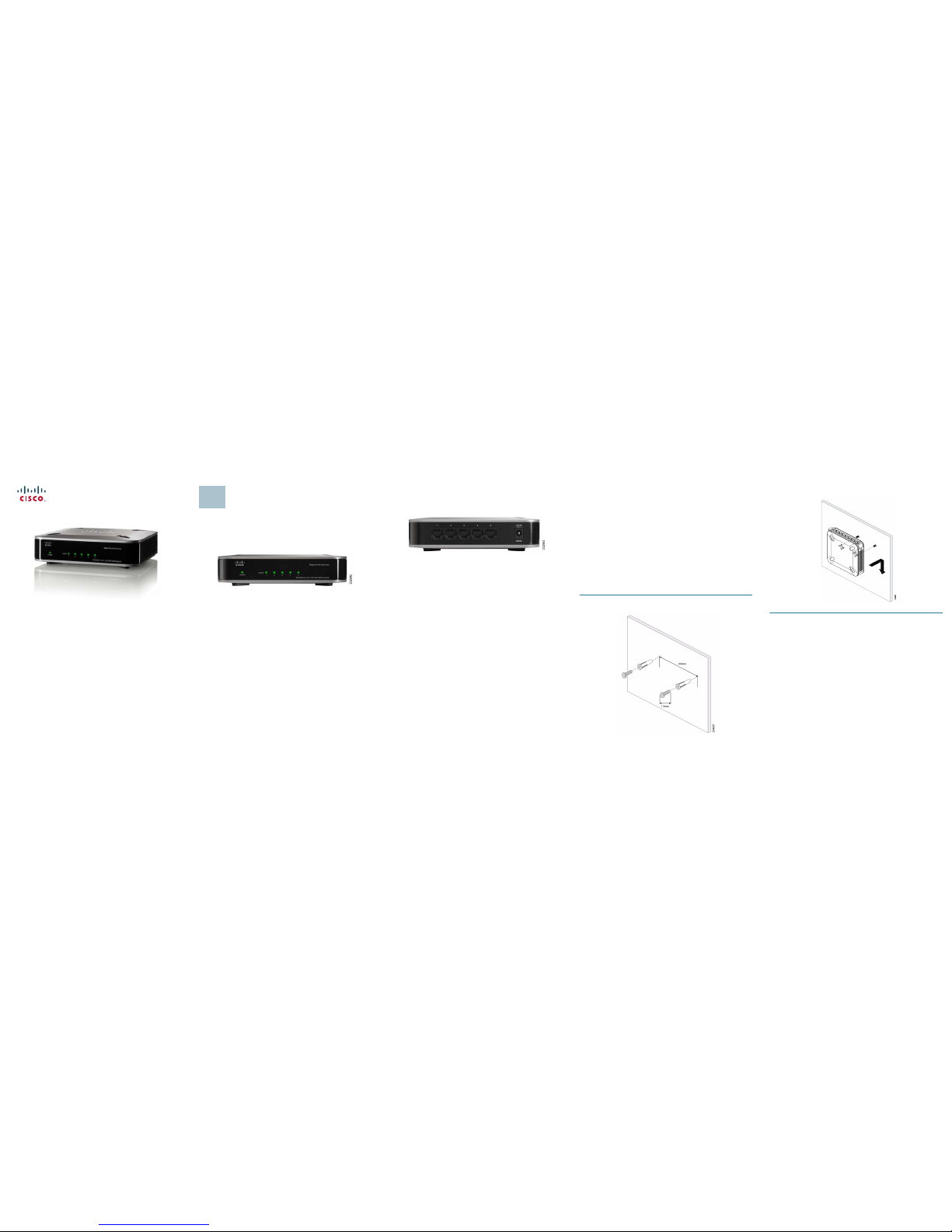
Model SD2005
5-Port 10/100/1000 Switch
Package Contents
• SD2005 Switch
• Power Adapter
• Quick Start Guide
Product Overview
Thank you for choosing the Cisco 5-Port 10/100/1000 Switch. The Switch
provides non-blocking, wire speed switching for your 10, 100, and 1000 Mbps
network clients.
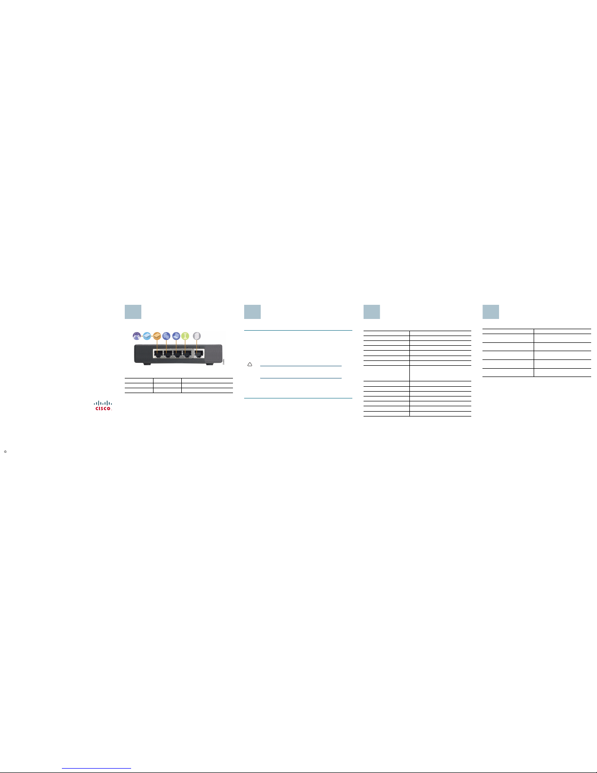
Front Panel
The LEDs are located on the front panel of the Switch.
System—(Green) This LED lights up and remains lit when the Switch is
powered on.
Link/ACT (Ports 1-5)—(Green) Each LED lights up when a connection is made
through its corresponding port. It flashes when the corresponding port is active.
1
Back Panel
The Power Port and Ethernet network ports are located on the back panel of the
Switch. All ports are auto-negotiating and have automatic MDI/MDI-X crossover
detection.
1-5—These ports connect the Switch to network devices, such as computers.
Power—External power adapter with 12V/0.5A DC output must support 100/
240 V and 50/60 Hz inputs.
The power port is where you will connect the power adapter.
Side Panels
There is a physical security slot located on the side of the Switch. The security
slot is where you can attach a lock to protect the Switch from theft.
Placement Options
Set the Switch on its four rubber feet, or mount the Switch on a wall.
The Switch offers two wall-mount slots, which are the two crisscross slots on
the bottom panel. The measurement between the two slots is 2.52 inches
(64 mm).
Before mounting the switch onto a wall, it is important to consider the following:
• Ensure the wall is strong enough to support the switch, a minimum of 1/2” of
sheet rock is recom mended.
• Do not operate the switch in an area that has reduced air flow, or exceeds
an ambient temperature of 104º (40ºC).
• The switch can be mounted either horizontal or vertical.
• Mounting screws should have a head 5.5mm wide, 2mm deep, and the shaft
of the screw should be at least 13mm long and 2.9mm wide.
To use the wall-mount option, follow these instructions:
STEP1 The wall-mount slots are two crisscross slots on the Switch’s
bottom panel. Attach two screws to the wall 64m m apart.
STEP 2 Maneuver the Switch to insert the screws into the two slots, then slide
the switch downward onto the screws.
Page 2
Americas Headquarters
Cisco Systems, Inc.
170 West Tasman Drive
San Jose, CA 95134-1706
USA
http://www.cisco.com
Tel: 408 526-4000
800 553-NETS (6387)
Fax:408 527-0883
Cisco, Cisco Systems, the Cisco logo, and the Cisco Systems logo are registered trademarks or
trademarks of CiscoSyst ems, Inc. and/or its affiliates in the UnitedStates and certain other
countries. All other trademarks mentioned in this document or Website are the property of their
respective owners. The use of the word partner does not imply a partnership relationship
between Cisco and any other company. (0705R)
© 2008 Cisco Systems, Inc. All rights reserved.
Printed in the USA on recycled paper containing 10% postconsumer waste.
78-18926-01
Typical Installation Scenario
The application diagram shown here is an example of a typical network
configuration.
When you connect your network devices, make sure you don’t exceed the
maximum cabling distances, which are listed in the following table:
From To Maximum Distance
Switch Switch 100 meters (328 feet)
Switch Computer 100 meters (328 feet)
2
Installation
Perform the steps in this section to install the hardware.
STEP1 Connect a Category 5 Ethernet network cable to one of the
numbered ports on the Switch. Conne ct the other end to a
computer or other network device.
S
TEP 2 Repeat step 1 to connect additional devices.
S
TEP 3 Connect the supplied power adapter to the power port on the Switchs
back panel. Plug the other end of the adapter into an electrical outlet.
!
CAUTION Make sure you use the power adapter included with the
Switch. Using a different power adapter may damage the
Switch.
S
TEP 4 Power on the devices connected to the Switch. LEDs will come on for
ports connected to powered devices.
Congratulations! The installation of the 10/100/1000 Switch is complete!
3
Specifications
The following table lists the specifications for the SD2005 10/100/1000
Ethernet Switch.
Item Specification
Model SD2005
Standards IEEE 802.3, 802.3u, 802.3x, 802.3ab
Ports 5 RJ-45 10/100/1000 Mbps ports
Cabling Type Cat5e
LEDs System, Link/Act 1 through 5
Security Feature Security Slot
Dimensions WxHxD
5.51" x 1.31" x 5.51"
140x33.35x140 mm
Unit Weight 0.606 lbs (0.275 kg)
Power DC12V/.5A
Certification FCC Cla ss B, CE
Operating Temperature 0ºC to 40ºC (32ºF to 104ºF)
Storage Temperature -40ºC to 70ºC (-40ºF to 158ºF)
Operating Humidity 20 to 95% Non-Condensing
Storage Humidity 5% to 90% Non-Condensing
4
Where to Go From Here
Resource Location
Customer Support www.cisco.com/web/products/
linksys/index.html
End User License Agreement www.cisco.com/web/products/
linksys/index.html
Regulatory Compliance and Safety
Information
www.cisco.com/web/products/
linksys/index.html
Warranty Information www.cisco.com/web/products/
linksys/index.html
Cisco Partner Central site for Small
Business
http://www.cisco.com/web/partners/
sell/smb/
5
 Loading...