

Page 1
Cisco Small Business
RV0xx Series Routers
RV042 Dual WAN VPN Router
RV042G Gigabit Dual WAN VPN Router
RV082 Dual WAN VPN Router
RV016 Multi-WAN VPN Router
ADMINISTRATION
GUIDE
Page 2

Cisco and the Cisco logo are trademarks or registered trademarks of Cisco and/or its affiliates in the U.S. and other countries. To view a list of Cisco trademarks,
go to this URL: www.cisco.com/go/trademarks. Third-party trademarks mentioned are the property of their respective owners. The use of the word partner
does not imply a partnership relationship between Cisco and any other company. (1110R)
© 2011-2012 Cisco Systems, Inc. All rights reserved. 78-19576-01 B0
Page 3

Contents
Chapter 1: Introduction 7
RV0xx Series Router Features 7
Ports 9
Status Lights 10
Other Hardware Features 11
Default Settings 12
Mounting Options 12
Placement Tips 12
Desktop Placement 12
Wall Mounting 13
Rack Mounting RV082 or RV016 14
Connecting the Equipment 15
Getting Started with the Configuration 16
Troubleshooting Tips 17
Features of the User Interface 18
Chapter 2: Viewing System Summary Information 20
Chapter 3: Setup 26
Setting Up the Network 27
Changing the Administrator Username and Password 40
Setting the System Time 42
Setting Up a DMZ Host 43
Setting Up Port Forwarding and Port Triggering 44
Setting Up Universal Plug and Play (UPnP) 48
Setting Up One-to-One NAT 51
Cloning a MAC Address for the Router 53
Assigning a Dynamic DNS Host Name to a WAN Interface 55
Setting Up Advanced Routing 57
IPv6 Transition 61
Cisco Small Business RV0xx Series Routers Administration Guide 3
Page 4

Contents
Chapter 4: DHCP 63
Setting Up the DHCP Server or DHCP Relay 63
Viewing the DHCP Status Information 70
Router Advertisement (IPv6) 71
Chapter 5: System Management 73
Setting Up Dual WAN and Multi-WAN Connections 73
Managing the Bandwidth Settings 81
Setting Up SNMP 84
Enabling Device Discovery with Bonjour 85
Using Built-In Diagnostic Tools 87
Restoring the Factory Default Settings 89
Upgrading the Firmware 90
Restarting the Router 91
Backing Up and Restoring the Settings 92
Chapter 6: Port Management 95
Configuring the Port Settings 95
Viewing the Status Information for a Port 97
Chapter 7: Firewall 99
Configuring the General Firewall Settings 99
Configuring Firewall Access Rules 103
Using Content Filters to Control Internet Access 110
Chapter 8: Cisco ProtectLink Web 113
Getting Started with Cisco ProtectLink Web 113
Specifying the Global Settings for Approved URLs and Clients 115
Approved URLs and Approved Clients 116
Enabling Web Protection for URL Filtering 117
Cisco Small Business RV0xx Series Routers Administration Guide 4
Page 5

Updating the ProtectLink License 120
Contents
Chapter 9: VPN 122
Introduction to VPNs 122
Site to Site VPN (Gateway To Gateway) 123
Remote Access (Client To Gateway) 123
Remote Access with Cisco QuickVPN 125
Remote Access with PPTP 125
Viewing the Summary Information for VPN 126
Setting Up a Gateway to Gateway (Site to Site) VPN 130
Setting Up a Remote Access Tunnel for VPN Clients (Client To Gateway)
139
Managing VPN Users and Certificates 147
Setting Up VPN Passthrough 149
Setting Up PPTP Server 150
Chapter 10: Logging System Statistics 153
Setting Up the System Log and Alerts 153
Viewing the System Log 157
Chapter 11: Wizard 159
Appendix A: Glossary 161
Appendix B: Troubleshooting 165
Appendix C: Cisco QuickVPN for Windows 167
Introduction 167
Cisco QuickVPN Client Installation and Configuration 168
Using the Cisco QuickVPN Software 168
Cisco Small Business RV0xx Series Routers Administration Guide 5
Page 6

Contents
Appendix D: Configuring a Gateway-to-Gateway VPN Tunnel Between RV0xx Series Routers 170
Topology Options 170
VPN Hub and Spoke Topology 171
VPN Mesh Topology 172
Other Design Considerations 173
Configuring a VPN Tunnel on a Cisco RV0xx Series Router 175
Example: Sites with Static WAN IP Addresses 176
Example: Site with a Dynamic WAN IP Address 179
Appendix E: IPSec NAT Traversal 183
Overview 183
Appendix F: Bandwidth Management 186
Creation of New Services 186
Creation of New Bandwidth Management Rules 187
Appendix G: Specifications 189
RV042 189
RV042G 191
Cisco RV082 194
Cisco RV016 196
Appendix H: Where to Go From Here 199
Cisco Small Business RV0xx Series Routers Administration Guide 6
Page 7

Introduction
Thank you for choosing a RV0xx Series VPN Router. This guide provides complete
information to help you configure and manage your router. This chapter includes
information to help you get started using your router. Refer to these topics:
1
• RV0xx Series Router Features, page 7
• Mounting Options, page 12
• Connecting the Equipment, page 15
• Getting Started with the Configuration, page 16
• Features of the User Interface, page 18
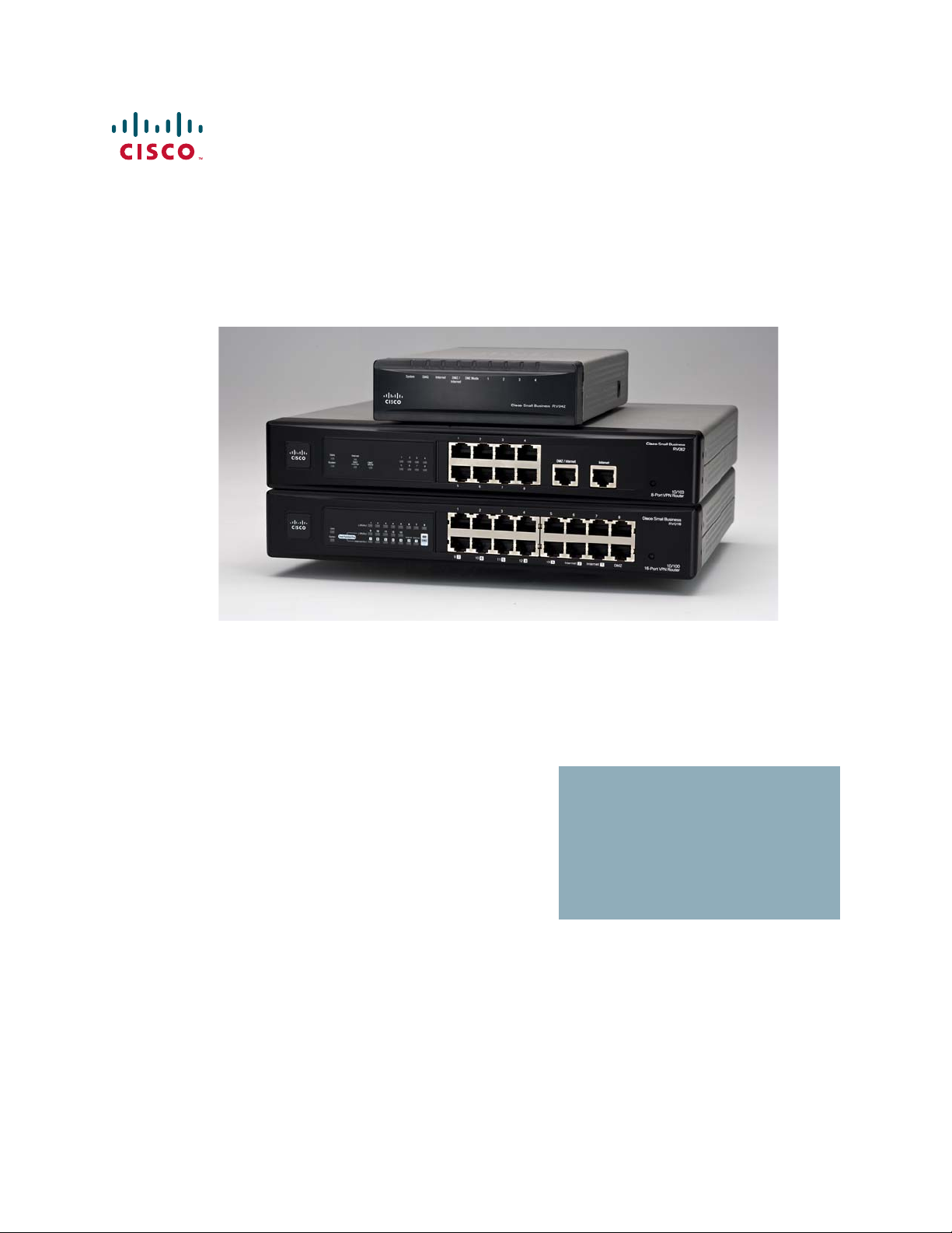
RV0xx Series Router Features
Cisco RV0xx Series dual WAN and multi-WAN VPN routers offer highly secure,
high-performance, reliable connectivity. All of these routers can support a second
Internet connection to ensure continuous connectivity or to increase available
bandwidth and balance traffic. Three models are available. A comparison is
provided below.
Model LAN
RV042 and RV042G 42
RV082 82
RV016 8-13 2-7 Internet
Ports
WAN/DMZ
Ports
1DMZ
NOTE RV042, RV042G, and RV082 have one dedicated Internet port and a DMZ/Internet
port. RV016 has two dedicated Internet ports, one dedicated DMZ port, and five
dual-function ports that can be configured as LAN or Internet ports.
Cisco Small Business RV0xx Series Routers Administration Guide 7
Page 8
Introduction
278823
DMZ/Internet1 2 3 4 Internet
Cisco Small Business RV042
System DIAG DMZ/
Internet
DMZMode 1 2 3 4Internet
278822
278824
12 3 4
56 7 8
DMZ/Internet Internet
1234
5678
DIAG
System
Internet
DMZ
Internet
DMZ
Mode
Cisco Small Business
RV082
10/100
16-Port VPN Router
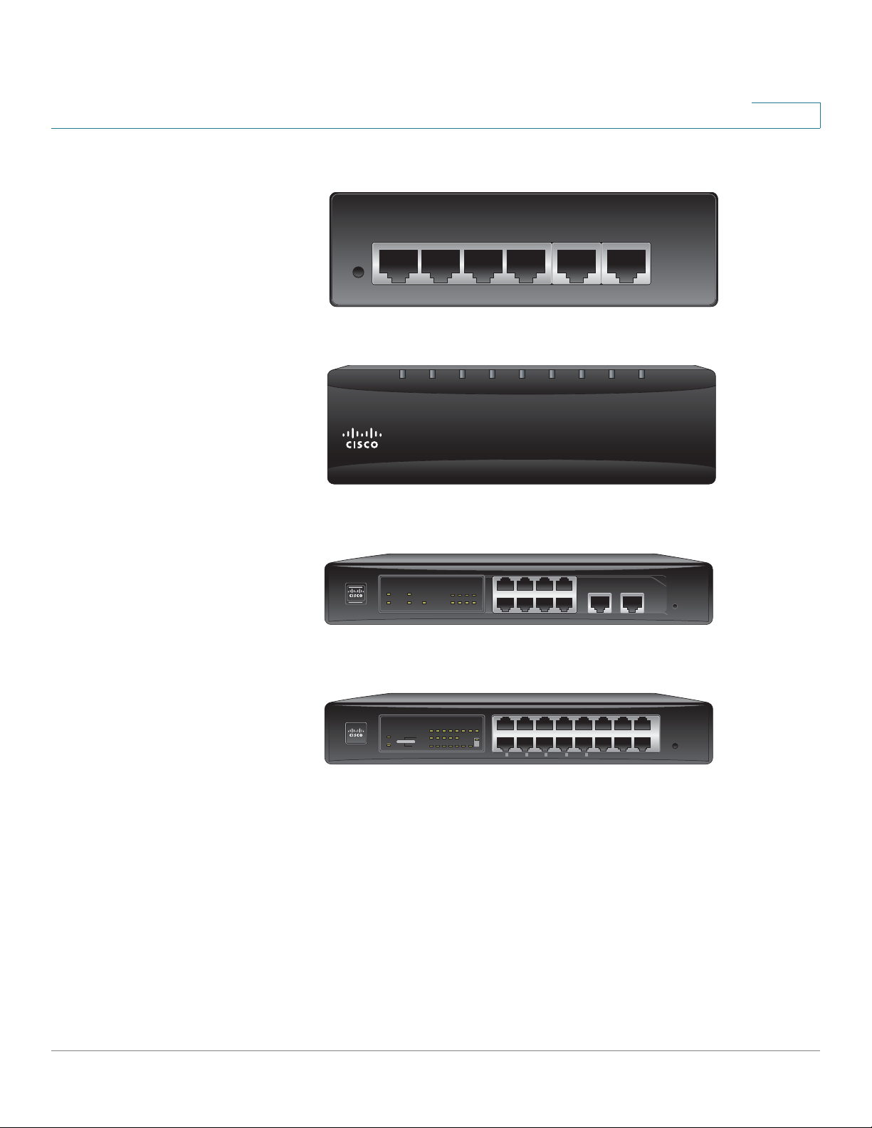
RV0xx Series Router Features
1
RV042 and RV042G Ports
RV042 and RV042G Status Lights
RV082 Ports and Status Lights
RV016 Ports and Status Lights
12345678
LAN/Act
DIAG
System
Dual-Function Ports
910111213
LAN/Act
7654321
Internet/Act
Internet Internet
DMZ
12345678
97 106 115 124 133
Internet 2 Internet 1 DMZ
Cisco Small Business
16-Port VPN
RV016
10/100
278826
Cisco Small Business RV0xx Series Routers Administration Guide 8
Page 9

Introduction
RV0xx Series Router Features
1
Ports
Port Description
Internet (RV042
and RV082) or
Internet 1-2
(RV016)
DMZ/Internet
(RV042 and
RV082)
DMZ (RV016) Use this port to connect the router to a DMZ
1-4 (RV042 and
RV042G) or 1-8
(RV082 and
RV016)
Use this port to connect the router to a
broadband network device.
Use this port to connect the router to either
a second broadband network device or a
DMZ host such as a web server or FTP
server. A DMZ allows public Internet traffic
to access a specified computer on your
network without exposing your LAN.
host such as a web server or FTP server. A
DMZ allows public Internet traffic to access
a specified computer on your network
without exposing your LAN.
Use these numbered ports to connect
computers and other local network devices.
9-13 and 3-7 Dual
Function Ports
(RV016)
Cisco Small Business RV0xx Series Routers Administration Guide 9
Use these numbered ports as LAN ports
(numbered 9-13) or configure them for use
as Internet ports (numbered 3-7). The status
is shown on the corresponding status lights:
LAN/Act 9-13 or Internet/Act 3-7.
Page 10

Introduction
RV0xx Series Router Features
1
Status Lights
Light Description
DIAG Lit—The router is preparing for use. Unlit—
The router is ready for use.
System Steady—The router is powered on.
Flashing—The router is running a
diagnostic test.
Internet (RV082,
RV042, RV042G)
or Internet 1-2
(RV016)
DMZ/Internet
(RV082, RV042,
RV042G) or DMZ
(RV016)
DMZ Mode
(RV082, RV042,
RV042G)
1-4, 1- 8 St eady —A device is connected to the
RV042G Gigabit
Ports
Steady—A device is connected to the
Internet port. Flashing—There is network
activity over the Internet port.
Steady—A device is connected to the
DMZ/Internet or DMZ port. Flashing—
There is network activity over the port.
Lit—The DMZ/Internet port is configured
as a DMZ. Unlit—The DMZ/Internet port is
configured as a secondary Internet
connection.
numbered LAN port. Flashing—There is
network activity over the numbered port.
For the Internet, DMZ/Internet, and
numbered ports, the color indicates the
speed. Green—Gigabit. Amber—10/100M.
RV016 Dual-Function Ports:
LAN/Act 9-13 Lit if the port is configured as a LAN port.
Steady—A device is connected to the port.
Flashing—There is network activity over
the port.
Internet/Act 3-7
(RV016)
Cisco Small Business RV0xx Series Routers Administration Guide 10
Lit if the port is configured as an Internet
port. Steady—A device is connected to the
port. Flashing—There is network activity
over the port.
Page 11

Introduction
RV0xx Series Router Features
1
Other Hardware Features
Feature Description
Reset The Reset button is an indented black
button. On the back panel of the RV042 and
RV042G, look for this button near the port
labeled 1. On the front panel of the RV082
and RV016, look for this button near the
Internet and DMZ ports .
• To restart the router or restore
connectivity: If the router is having
problems connecting to the Internet,
use the tip of a pen to press and hold
the Reset button for one second.
• To restore factory default settings:
If you are experiencing extreme
problems with the router and have
tried all other troubleshooting
measures, press and hold the Reset
button for 30 seconds to restore the
factory default settings. All
previously entered settings will be
abandoned.
Security Slot Use the security slot on the side panel to
attach a lock to protect the router from theft.
Power • RV042 and RV042G: Connect the
provided power adapter to the
power port on the side panel.
• RV082 and RV016: Connect the
provided AC power cable to the
power port on the back panel.
Cisco Small Business RV0xx Series Routers Administration Guide 11
Page 12

Introduction
Mounting Options
Default Settings
Parameter Default Value
Username admin
Password admin
LAN IP 192.168.1.1
DHCP Range 192.168.1.100 to 149
Netmask 255.255.255.0
Mounting Options
1
Placement Tips
• Ambient Temperature—To prevent the router from overheating, do not
operate it in an area that exceeds an ambient temperature of 104°F (40°C).
• Air Flow—Be sure that there is adequate air flow around the router.
• Mechanical Loading—Be sure that the router is level and stable to avoid
any hazardous conditions.
Desktop Placement
Place the router on a flat surface near an electrical outlet.
WARNING Do not place anything on top of the router; excessive weight could damage it.
Cisco Small Business RV0xx Series Routers Administration Guide 12
Page 13
Introduction
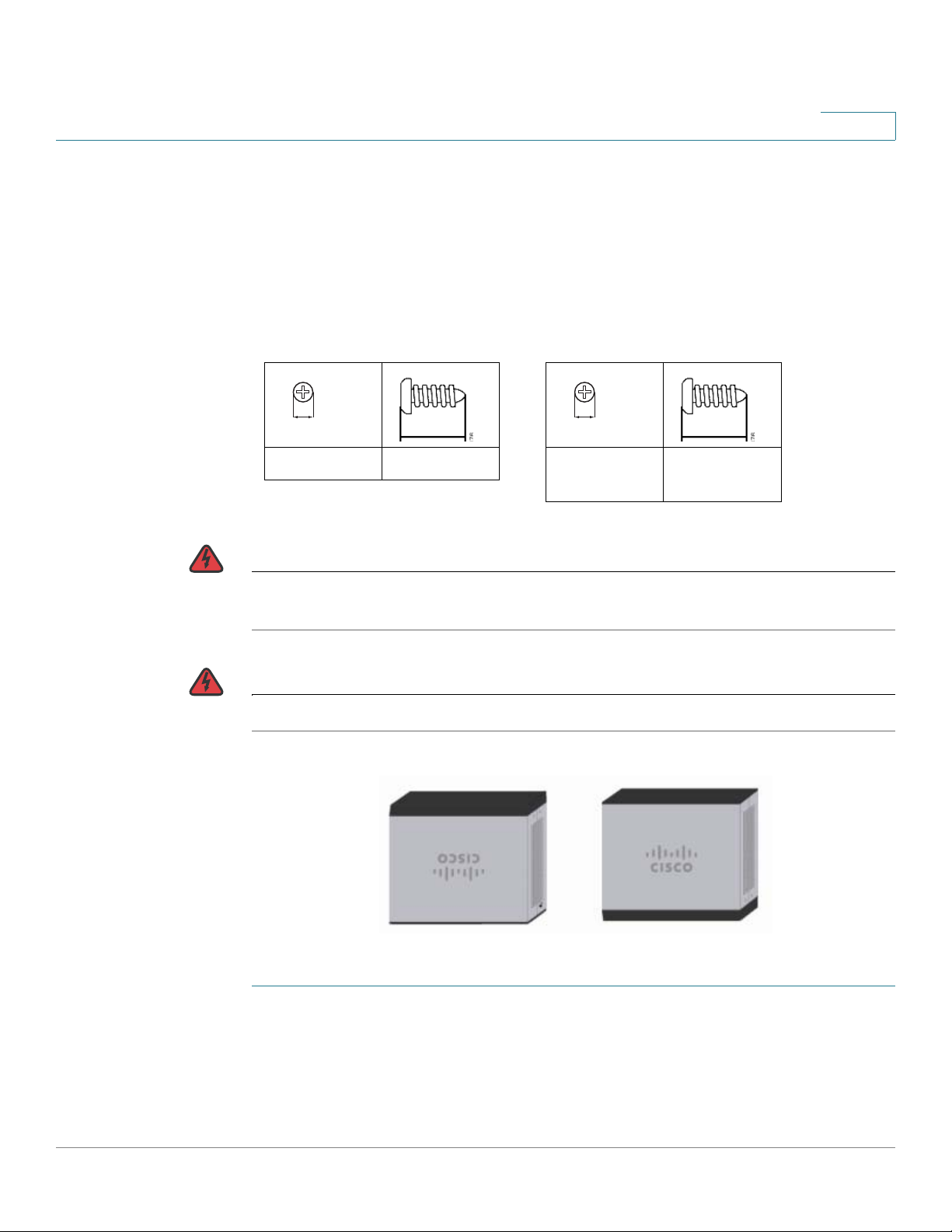
Suggested Hardware for
RV042 and RV042G
Suggested Hardware for
RV082 and RV016
5-5.5 mm 20-22 mm
6.5-7 mm 16.5-18.5
mm
Mounting Options
1
Wall Mounting
The router has two wall-mount slots on the bottom panel. To mount the router on a
wall, you need mounting hardware (not included). Suggested hardware is
illustrated below (not true to scale).
WARNING Insecure mounting might damage the router or cause injury. Cisco is not
WARNING
STEP 1 Drill two pilot holes into the surface.
responsible for damages incurred by insecure wall-mounting.
For safety, ensure that the heat dissipation holes are facing sideways
• RV042 and RV042G: 58 mm apart
• RV082 and RV016: 94 mm apart
.
Cisco Small Business RV0xx Series Routers Administration Guide 13
Page 14
Introduction
!
1 2 3 4
5 6
7 8
DMZ/InternetInternet
123 4
5 6 7 8
DI
AG
S
y
s
te
m
Internet
DM
Z
Internet
DMZ
Mode
Cisco Small B
usin
ess
RV
082
10/100
16-P
ort VPN
Rou
t
er
278825
1
2
123 4
5678
DMZ/Int
e
rnet Inte
rnet
1
234
5
6 7
8
D
IA
G
Sy
s
tem
I
nterne
t
DMZ
I
nterne
t
D
MZ
Mode
Cisco Sma
ll Busin
ess
RV
082
10/100
16-
P
ort VP
N Rou
te
r
Mounting Options
1
STEP 2 Insert a screw into each hole, leaving a gap between the surface and the base of
the screw head of 1 to 1.2 mm.
STEP 3 Place the router wall-mount slots over the screws and slide the router down until
the screws fit snugly into the wall-mount slots.
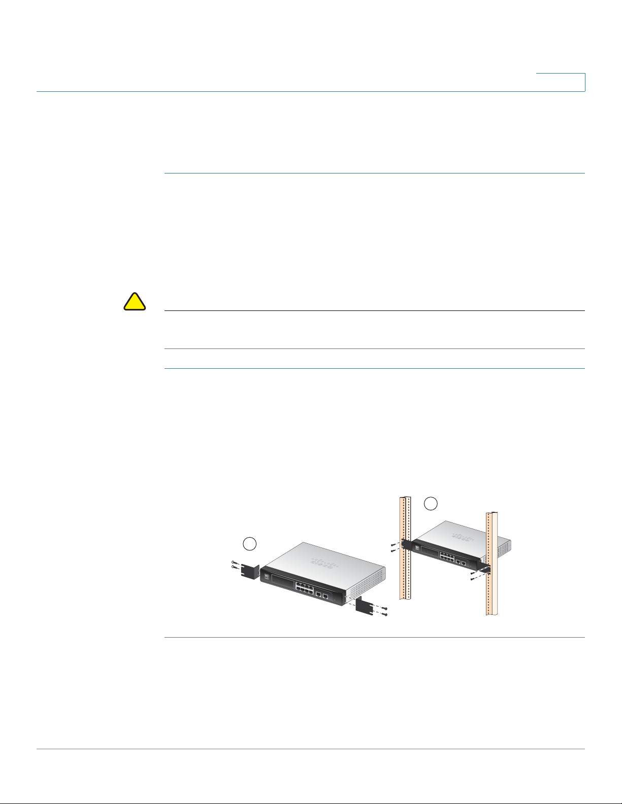
Rack Mounting RV082 or RV016
You can mount the RV082 or RV016 in a standard size, 19-inch (about 48 cm) wide
rack. The router requires 1 rack unit (RU) of space, which is 1.75 inches (44.45mm)
high. Mounting brackets are provided.
CAUTION Do not overload the power outlet or circuit when installing multiple devices in a
rack.
STEP 1 Place the router on a hard, flat surface.
STEP 2 Attach one of the supplied rack–mount brackets to one side of the router with the
supplied screws. Secure the bracket tightly.
STEP 3 Follow the same steps to attach the other bracket to the opposite side.
STEP 4 Use suitable screws to securely attach the brackets to any standard 19-inch rack.
Cisco Small Business RV0xx Series Routers Administration Guide 14
Page 15
Introduction
199619
DMZ/Internet1 2 3 4 Internet
199621
Cisco Small Business
RV016
10/100
16-Port VPN
12345678
97 10 6 11 5 124 133
Internet 2 Internet 1 DMZ
12345678
910111213
7654321
DIAG
System
LAN/Act
LAN/Act
Internet/Act
Internet Internet
Dual-Function Ports
DMZ
Connecting the Equipment
Connecting the Equipment
STEP 1 Make sure that all network devices are powered off, including the router, PCs,
Ethernet switches, and broadband network device (DSL or cable modem).
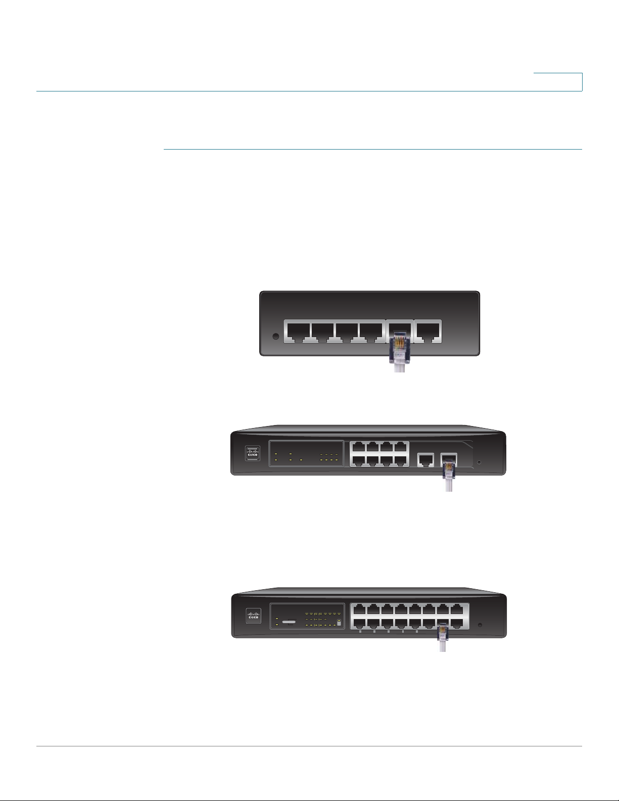
STEP 2 To connect to your Internet service:
• RV042, RV042G, and RV082: Connect an Ethernet cable from the
broadband network device to the Internet port of the router.
RV042 and RV042G Internet Port
1
RV082 Internet Port
12 3 4
DIAG
Internet
DMZ
System
Internet
1234
DMZ
Mode
5678
56 7 8
• RV016: Connect an Ethernet cable from the broadband network device to
the Internet 1 port of the router.
RV016 Internet 1 Port
STEP 3 To connect a secondary Internet service:
DMZ/Internet Internet
Cisco Small Business
16-Port VPN Router
RV082
10/100
199620
• RV042, RV042G, and RV082: Connect an Ethernet cable from the DMZ/
Internet port to a second broadband network device.
Cisco Small Business RV0xx Series Routers Administration Guide 15
Page 16

Introduction
Getting Started with the Configuration
• RV016: Connect an Ethernet cable from the Internet 2 port to a second
broadband network device.
STEP 4 To connect a computer or server that will be a DMZ host:
• RV042, RV042G, and RV082: Connect an Ethernet cable from the DMZ/
Internet port to the DMZ host.
• RV016: Connect an Ethernet cable from the DMZ port to the DMZ host.
STEP 5 To connect other network devices, such as computers, print servers, or Ethernet
switches, connect an Ethernet cable from a numbered LAN port to the network
device.
STEP 6 Power on the broadband network device(s).
STEP 7 Use the power adapter (RV042 and RV042G) or the power cable (RV082 and
RV016) to connect the router to a power outlet. The System status light is green.
1
STEP 8 Power on the other network devices.
Getting Started with the Configuration
STEP 1 Connect a computer to a numbered LAN port on the router. Your PC will become a
DHCP client of the router and will receive an IP address in the 192.168.1.x range.
STEP 2 Start a web browser. To use the configuration utility, you need a PC with Internet
Explorer (version 6 and higher), Firefox, or Safari (for Mac).
STEP 3 In the address bar, enter the default IP address of the router: 192.168.1.1
STEP 4 When the login page appears, enter the default user name admin and the default
password admin (lowercase).
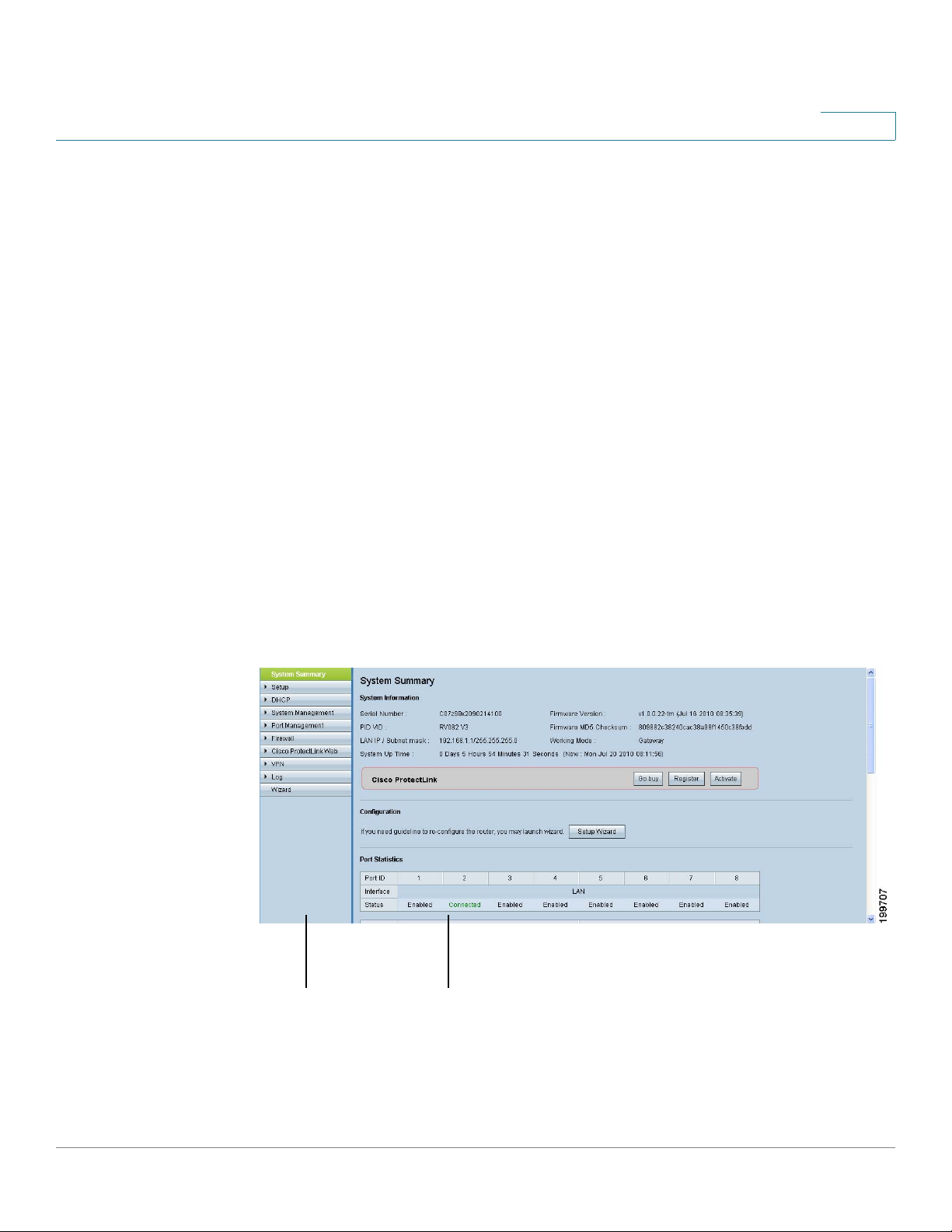
STEP 5 Click Login. The System Summary page appears.
The router’s default settings are sufficient for many small businesses. Your Internet
Service Provider may require additional settings. On the System Summary page,
check the WAN Status to see if the router was able to receive an IP Address. If not,
continue to the next step.
Cisco Small Business RV0xx Series Routers Administration Guide 16
Page 17

Introduction
Getting Started with the Configuration
STEP 6 To use the setup wizard to configure your Internet connection, click Setup Wizard
on the System Summary page, or click Wizard in the navigation tree. In the Basic
Setup section, click Launch Now. Follow the on-screen instructions.
If your web browser displays a warning message about the pop-up window, allow
the blocked content.
STEP 7 To configure other settings, use the links in the navigation tree.
Cisco strongly recommends setting a strong administrator password to prevent
unauthorized access to your router. For more information about all settings, refer to
the online Help and the Cisco Small Business RV0xx Series VPN Router
Administration Guide.
Troubleshooting Tips
1
If you have trouble connecting to the Internet or the web-based configuration
utility:
• Verify that your web browser is not set to Work Offline.
• Check the Local Area Connection settings for your Ethernet adapter. The PC
needs to obtain an IP address through DHCP. Alternatively, it can have a
static IP address in the 192.168.1.x range with the default gateway set to
192.168.1.1 (the router’s default IP address).
• Verify that you entered the correct settings in the Wizard to set up your
Internet connection, including the username and password if required.
• Try resetting the modem and the router by powering off both devices. Next,
power on the modem and let it sit idle for about 2 minutes. Then power on
the router. You should now receive a WAN IP address.
• Check the DHCP IP address range of your modem. If the modem uses the
192.168.1.x range, disconnect the cable from the modem to the router, and
then launch the router configuration utility. In the navigation tree, choose
Setup > Network. Enter a new Device IP Address, such as 10.1.1.1 or
192.168.0.1. Alternatively, if you have a DSL modem, leave all settings as is
and instead ask your ISP to put the DSL modem into bridge mode.
Cisco Small Business RV0xx Series Routers Administration Guide 17
Page 18
Introduction
1 2
Features of the User Interface
Features of the User Interface
The user interface is designed to make it easy for you to set up and manage your
router. Refer to these topics:
• Navigation, page18
• Pop-Up Windows, page 19
• Setup Wizards, page 19
• Saving the Settings, page19
• Help, page 19
• Logout, page 19
1
Navigation
The major modules of the configuration utility are represented by buttons in the
left navigation pane. Click a button to view more options. Click an option to open a
configuration page. The selected page appears in the main window of the
configuration utility.
1. Navig at io n t re e
2. Configuration page
Cisco Small Business RV0xx Series Routers Administration Guide 18
Page 19

Introduction
Features of the User Interface
1
Pop-Up Windows
Some links and buttons launch pop-up windows that display more information or
related configuration pages. If your web browser displays a warning message
about the pop-up window, allow the blocked content.
Setup Wizards
Two setup wizards make it easy to set up your Internet connection and/or DMZ
and to configure access rules for the WAN, LAN, and DMZ. You can use these
wizards or use the other pages of the configuration utility.
To open the Wizard page: Click the Setup Wizard button in the Configuration
section of the System Summary page. Alternatively, click Wizard in the navigation
tree. There are two wizards:
• Basic Setup: Click Launch Now to configure the basic settings for your
Internet connection and DMZ. Follow the on-screen instructions.
• Access Rule Setup: Click Launch Now to configure access rules for the
WAN, LAN, and DMZ. Follow the on-screen instructions.
Saving the Settings
Your settings on a configuration page are not saved until you click the Save button.
When you navigate to another page, any unsaved settings are abandoned.
To clear the settings without saving them, you can click the Cancel button.
Help
To view more information about the selected configuration page, click the Help link
near the top right corner of the configuration utility. If your web browser displays a
warning message about the pop-up window, allow the blocked content.
Logout
To exit the configuration utility, click the Logout link near the top right corner of the
configuration utility. The Login page appears. You can close the browser window.
Cisco Small Business RV0xx Series Routers Administration Guide 19
Page 20
Viewing System Summary Information
The
System Summary
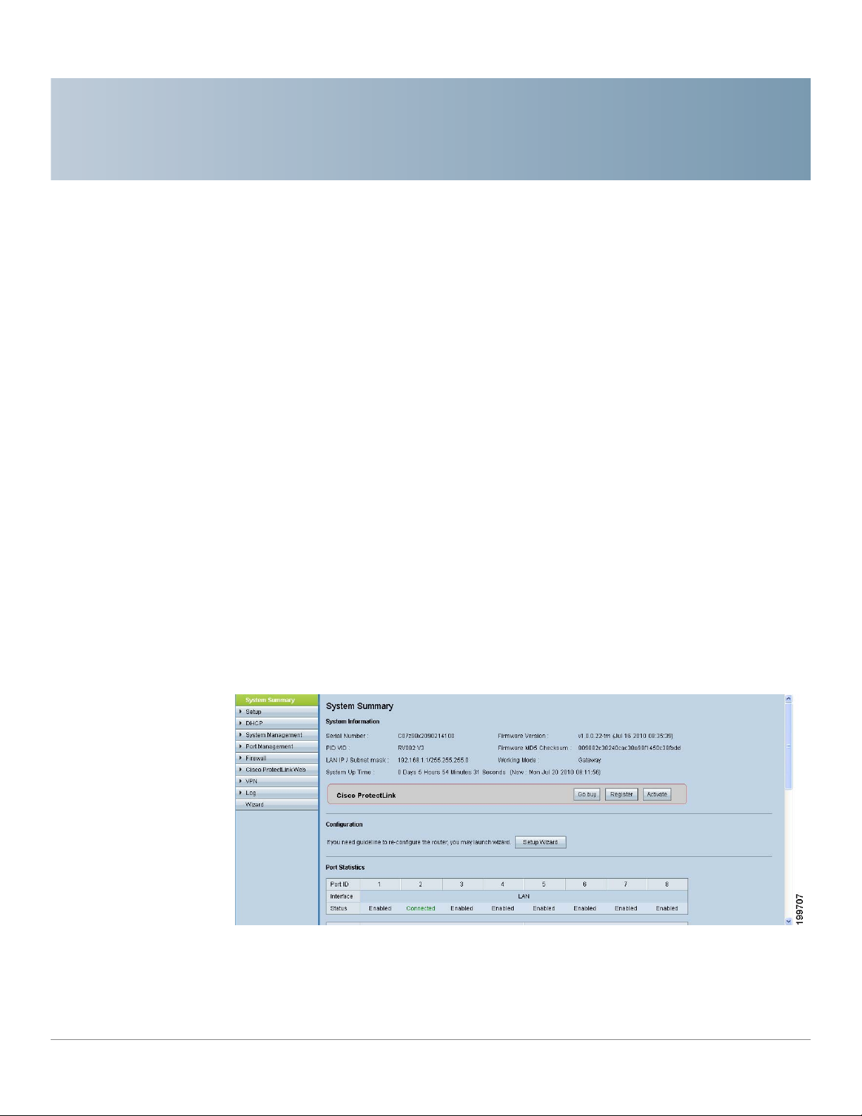
You also can view this page by clicking System Summary in the navigation tree.
Use this page to view information about the current status of the router and the
settings. Refer to these topics:
• System Information, page 21
• Cisco ProtectLink Web, page 21
page appears after you log in to the configuration utility.
2
• Configuration, page 22
• Port Statistics, page 22
• WAN Status, page 24
• Firewall Setting Status, page 25
• VPN Setting Status, page 25
• Log Setting Status, page 25
Cisco Small Business RV0xx Series Routers Administration Guide 20
Page 21

Viewing System Summary Information
System Information
This section includes the following information:
• Serial Number: The serial number of the router.
• Firmware version: The current version number of the firmware installed on
the router.
• PID VID: The current version number of the hardware.
• MD5 Checksum: A value used for file validation.
• LAN IP / Subnet mask: The current IP Address of the router on the local
network.
• Working Mode: The working mode (Gateway or Router).
• LAN: If Dual-Stack IP is enabled, on the Setup > Network page, this section
displays the IPv4 address and subnet mask as well as the IPv6 address and
prefix length.
2
• System Up time: The length of time in days, hours, and minutes that the
router has been active.
Cisco ProtectLink Web
This section displays buttons for the optional Cisco ProtectLink Web service.
ProtectLink Web provides security for your network. It filters website addresses
(URLs) and blocks potentially malicious websites. (Also see Chapter 8, “Getting
Started with Cisco ProtectLink Web.”)
NOTE This service is not available on Cisco RV042G.
You can use the following buttons:
• Go buy: Click this button to purchase a license to use this service. You will
be redirected to a list of Cisco resellers on the Cisco website. Then follow
the on-screen instructions.
• Register: Click this button if you have a license but have not yet registered
it. You will be redirected to the Cisco ProtectLink Web website. Then follow
the on-screen instructions.
• Activate: Click this button if you have registered for Cisco ProtectLink Web
service and wish to activate it. You will be redirected to the Cisco
ProtectLink Web website. Follow the on-screen instructions.
NOTE If the Cisco ProtectLink Web options are not displayed on the
page, you can upgrade the router’s firmware to enable this feature.
Cisco Small Business RV0xx Series Routers Administration Guide 21
System Summary
Page 22

Viewing System Summary Information
Configuration
If you need help to configure the router, click Setup Wizard. You can then use
these wizards:
• Basic Setup Wizard: Use this wizard to set up your Internet connection.
• Access Rule Setup Wizard: Use this Wizard to set up the security policy
for your VPN.
Port Statistics
This table shows the status and available statistics for each port. It also provides
access to detailed information about current link activity.
• Port ID: The port label.
• Interface: The type of interface, such as LAN, WAN, or DMZ. Multiple WAN
interfaces are indicated by a number, such as WAN1 or WAN2.
2
• Status: The status of the port: Disabled (red), Enabled (black), or
Connected (green). The status is a hyperlink that you can click to open the
Port Information window.
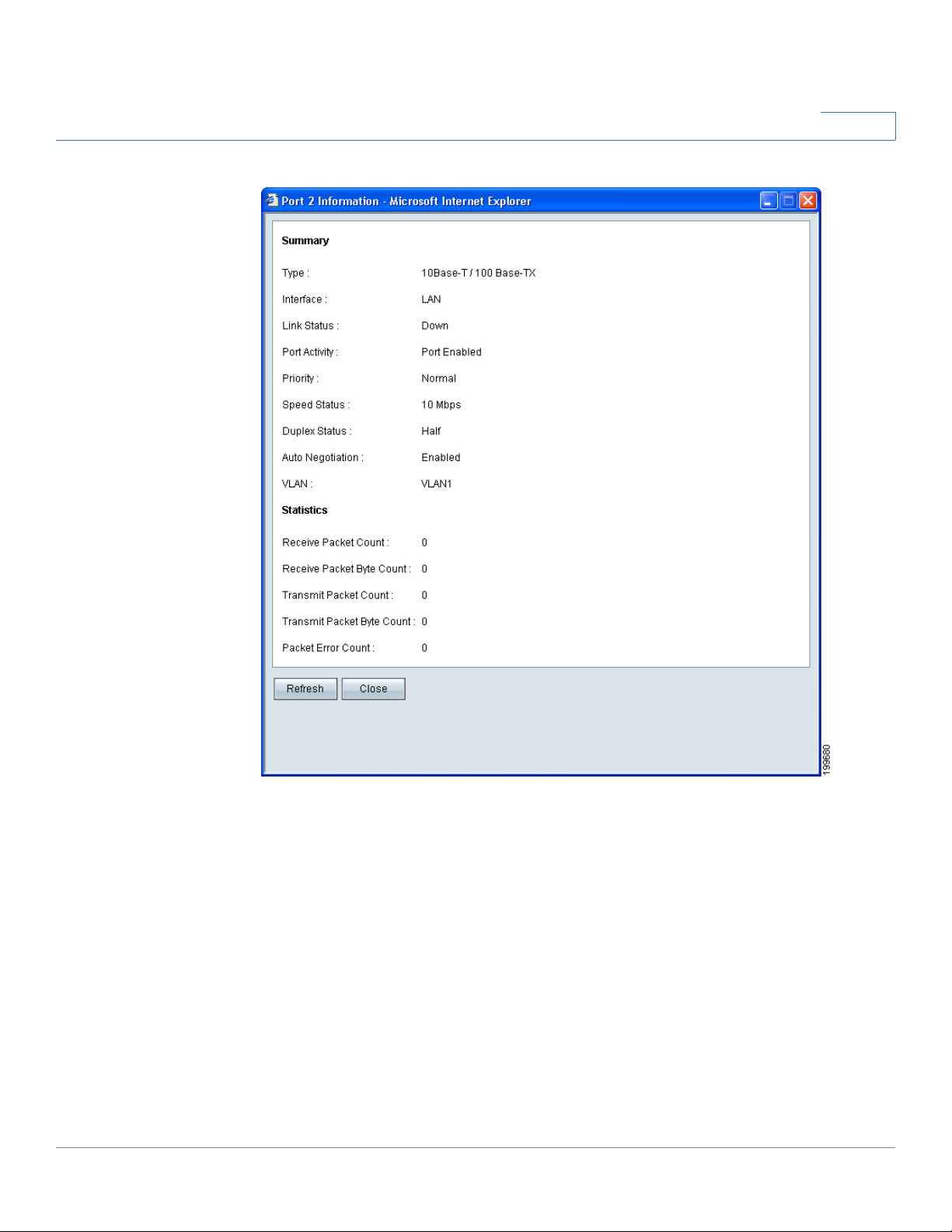
Port Information Window
If you click a status in the Port Statistics table, the Port Information window
appears. This window displays the latest information about the interface
and the current activity. To update the displayed information, click the
Refresh button. To close the window, click the Close button.
Cisco Small Business RV0xx Series Routers Administration Guide 22
Page 23
Viewing System Summary Information
2
This window displays the following information:
- Type: The type of port, 10Base-T/100 Base-TX.
- Interface: The type of interface, such as LAN, DMZ, or WAN.
- Link Status: The current status of the link: Up or Down.
- Port Activity: The current activity on the port, either Port Enabled, Port
Disabled, or Port Connected.
- Priority: The priority setting, High or Normal.
- Speed Status: The speed, 10Mbps or 100Mbps.
- Duplex Status: The duplex mode, Half or Full.
Cisco Small Business RV0xx Series Routers Administration Guide 23
Page 24

Viewing System Summary Information
- Auto negotiation: The auto negotiation setting, On or Off.
- VLAN: The VLAN ID.
- Receive Packet Count: The number of packets received through this
port.
- Receive Packet Byte Count: The number of bytes received through this
port.
- Transmit Packet Count: The number of packets transmitted through
this port.
- Transmit Packet Byte Count: The number of bytes transmitted through
this port.
- Packet Error Count: The number of packet errors.
WAN Status
2
This section displays information for the WAN1 interface as well as DMZ or WAN2,
depending on your configuration. On Cisco RV016, additional WAN interfaces may
be configured. Use the tabs to view the IPv4 and IPv6 information.
NOTE The IPv6 tab is available if Dual-Stack IP is enabled on the Setup > Network page.
• WAN information:
- IP Address: The current public IP address for this interface.
- Default Gateway: The default gateway for this interface.
- DNS: The IP address of the DNS server for this interface.
- Dynamic DNS (IPv4 only): The DDNS settings for this port, Disabled or
Enabled.
- Release and Renew: These buttons appear if the port is set to obtain an
IP address automatically. Click Release to release the IP address, and
click Renew to update the DHCP lease time or to get a new IP address.
- Connect and Disconnect: These buttons appear if the port is set to
PPPoE or PPTP. Click Disconnect to disconnect from the Internet
service. Click Connect to re-establish the connection.
Cisco Small Business RV0xx Series Routers Administration Guide 24
Page 25

Viewing System Summary Information
• DMZ information:
- IP Address: The current public IP address for this interface.
- DMZ Host: The DMZ private IP address of the DMZ host. The default is
Disabled.
Firewall Setting Status
This section displays the following information:
• SPI (Stateful Packet Inspection): The status of this feature: On (green) or
Off (red).
• DoS (Denial of Service): The status of this feature, On (green) or Off (red).
• Block WAN Request: The status of this feature, On (green) or Off (red).
• Remote Management: The status of this feature, On (green) or Off (red).
2
• Access Rule: The number of access rules that have been set.
VPN Setting Status
This section displays the following information:
• Tunnel(s) Used: The number of VPN tunnels in use.
• Tunnel(s) Available: The number of VPN tunnels available.
Log Setting Status
This section displays the following information:
• Syslog Server: The status of the syslog server, On (green) or Off (red).
• Email Log: The status of the email log, On (green) or Off (red).
Cisco Small Business RV0xx Series Routers Administration Guide 25
Page 26

Setup
3
Use the Setup module to set up the basic functions of the router. Refer to these
topics:
• Setting Up the Network, page 27
• DMZ Setting, page 32
• Changing the Administrator Username and Password, page 40
• Setting the System Time, page 42
• Setting Up a DMZ Host, page 43
• Setting Up Port Forwarding and Port Triggering, page 44
• Setting Up Universal Plug and Play (UPnP), page 48
• Setting Up One-to-One NAT, page 51
• Cloning a MAC Address for the Router, page 53
• Assigning a Dynamic DNS Host Name to a WAN Interface, page 55
• Setting Up Advanced Routing, page 57
• IPv6 Transition, page 61
Cisco Small Business RV0xx Series Routers Administration Guide 26
Page 27
Setup
Setting Up the Network
Setting Up the Network
Use the Setup > Network page to set up your LAN, WAN (Internet connections),
and DMZ interface.
To open this page: Click Setup > Network in the navigation tree.
3
NOTE Before navigating away from this page, click Save to save your settings, or click
Cancel to undo them. Any unsaved changes are abandoned.
This page includes the following sections:
• Host Name and Domain Name, page 27
• LAN Setting (device IP address and subnets), page 28
• WAN Setting (Internet connection), page 31
• DMZ Setting, page 32
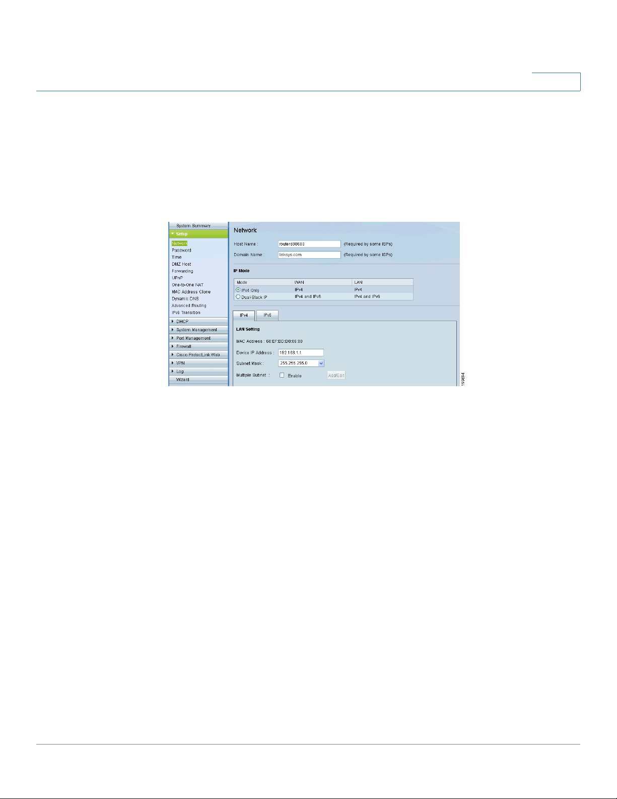
Host Name and Domain Name
Some ISPs require that you assign a host name and domain name to identify your
router on the ISP network. Default values are provided, but you can change them if
needed.
• Host Name: Keep the default setting or enter a host name specified by your
ISP.
• Domain Name: Keep the default setting or enter a domain name specified
by your ISP.
Cisco Small Business RV0xx Series Routers Administration Guide 27
Page 28

Setup
Setting Up the Network
3
IP Mode
Choose the type of addressing to use on your network:
• IPv4 Only—Use only IPv4 addressing.
• Dual-Stack IP—Use IPv4 and IPv6 addressing. After you enable this option
by saving the settings on this page, you can configure both IPv4 and IPv6
addresses for LAN, WAN, and DMZ settings on this page.
LAN Setting (device IP address and subnets)
The default LAN settings should be sufficient for most small businesses, but if
needed, you can change the LAN IP address of the router and enable multiple
subnets.
• Changing the device IP address, page 28
• Enabling multiple subnets (IPv4 only), page 29
NOTE If you enabled Dual-Stack IP for the IP Mode, you can click the IPv6 tab to configure
IPv6 addresses.
Changing the device IP address
STEP 1 Enter the following information:
• For IPv4: Click the IPv4 tab, and then enter the Device IP Address and
Subnet Mask. The default IP address is 192.168.1.1, and the default subnet
mask is 255.255.255.0.
Note: The MAC address of the router also appears in this section. This value
cannot be changed.
• For IPv6: Click the IPv6 tab, and then enter the IPv6 Address and the Prefix
Length. The default IP address is fc00::1, and the default prefix length is 7.
The IPv6 tab is available only if Dual-Stack IP is enabled in the IP Mode
section. If you change the IP Mode setting, you must save the settings before
you continue.
Note: To configure global IPv6 prefixes for your LAN devices, go to the WAN
Settings section, click the IPv6 tab, and click the Edit icon for the WAN
interface. Then enter the LAN IPv6 Address. For more information, see WAN
Setting (Internet connection), page 31.
STEP 2 Click Save to save your changes, or click Cancel to undo them.
Cisco Small Business RV0xx Series Routers Administration Guide 28
Page 29

Setup
Setting Up the Network
STEP 3 Release and renew the IP address of your PC. You should then receive a new IP
3
After you click Save, a pop-up window displays a reminder that you will need to
use the new device IP address to launch the configuration utility. Click OK to close
the message and continue with the IP address change, or click Cancel to close the
message without applying the changes.
address in the new DHCP range for the router.
Notes:
• To release and renew your address in Windows: From the Start menu, open
the Network Connections window. Right-click on the connection and
choose Disable. Right-click again and enable the connection. To verify, rightclick and choose Status. Then click the Support tab to view the assigned IP
address.
• By default, the router is a DHCP server that assigns IP addresses
dynamically to all connected devices. For example, if you choose
192.168.15.1 as the device IP address, devices will receive IP addresses in
the range of 192.168.2.x.
• By default, a Windows PC receives an IP address dynamically.
• If you previously disabled the router’s DHCP server or set a static IP address
on the PC, you will need to configure a new static IP address in the new
range.
STEP 4 To reconnect to the configuration utility, enter the new device IP address in the
address bar of your browser.
Enabling multiple subnets (IPv4 only)
Typically, a Cisco RV0xx Series router is used as an access router, with a single
LAN subnet. By default, the firewall is pre-configured to deny LAN access if the
source IP address is on a different subnet than the router’s LAN IP address.
However, you can enable multiple subnets to allow this router to work as an edge
device that provides Internet connectivity to different subnets in your LAN.
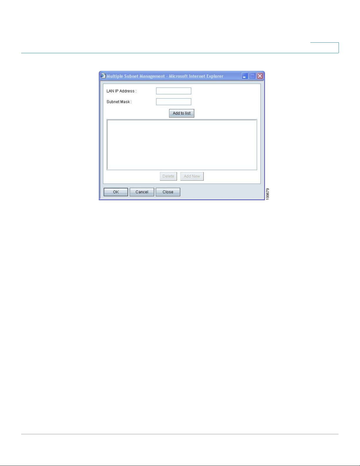
STEP 1 On the IPv4 tab, check the Enable Multiple Subnet box to enable this feature.
Uncheck the box to disable this feature.
STEP 2 Click Add/Edit to create or modify the subnets. After you click the button, the
Multiple Subnet Management window appears.
Cisco Small Business RV0xx Series Routers Administration Guide 29
Page 30
Setup
Setting Up the Network
3
STEP 3 In the pop-up window, add or edit entries as needed.
• To a dd a new su bn et : Enter a LAN IP Address and a Subnet Mask. Click Add
to list. The IP address and subnet mask appear in the list. Repeat this step
as needed to add other subnets.
Examples:
- Two subnets: If the router has a LAN IP address of 192.168.1.1 with a
subnet mask of 255.255.255.0, you could set up a second subnet with a
LAN IP address of 192.168.2.1 and a subnet mask of 255.255.255.0.
- Four subnets: If the router has a LAN IP Address of 192.168.1.1 and the
Subnet Mask of 255.255.255.192, you could create three subnets with IP
addresses of 192.168.2.65, 192.168.2.129, and 192.168.2.193, with the
same subnet mask of 255.255.255.192.
• To add another subnet: Enter the information, and then click Add to list.
• To modify a subnet: Click the subnet in the list. The existing values appear
in the text fields. Enter the new information, and then click Update. If you do
not want to modify the selected subnet, you can click Add New to clear the
text fields.
• To d ele te a su bn et: Click the subnet in the list, and then click Delete.
Cisco Small Business RV0xx Series Routers Administration Guide 30
Page 31

Setup
Setting Up the Network
STEP 4 When you finish entering settings in the Multiple Subnet window, click OK to save
NOTE You also can set up your Internet connection by using the Basic Setup Wizard. In the
3
your changes, or click Cancel to undo them.
WAN Setting (Internet connection)
The router is pre-configured with default settings that are sufficient for many
networks. However, special settings may be required by your ISP (Internet Service
Provider) or broadband (DSL or cable) carrier. Refer to the setup information
provided by your ISP.
navigation tree, click Wizard. In the Basic Setup section, click Launch Now.
The WAN S et ting table displays the existing settings for each interface, such as
DMZ, WAN1, or WAN2. The listed interfaces depend on the router model and the
settings that you enter for ports such as DMZ/Internet (all models) and the DualFunction ports (Cisco RV016).
Perform the following actions, as needed.
• To configure the WAN with IPv6 addressing: Click the IPv6 tab. Then
proceed with the other tasks listed below.
Note: The IPv6 tab is available only if Dual-Stack IP is enabled in the IP
Mode section. If you change the IP Mode setting, you must save the settings
before you continue.
• To change the number of WAN ports (Cisco RV016 only): Use the drop-
down list to choose the number of WAN ports that you want to enable. The
default selection is 2. If you configure additional WAN ports, the DualFunction Ports are used for this purpose.
Cisco Small Business RV0xx Series Routers Administration Guide 31
Page 32

Setup
Setting Up the Network
3
• To modify the WAN settings: If you have any unsaved changes on the
Network page, click Save to save your settings before continuing. For the
interface that you want to modify, click the Edit icon to open the Edit WAN
Connection page. For more information, see Editing a WAN Connection,
page 34.
DMZ Setting
On Cisco RV042, RV042G, and RV082, you can configure the Internet/DMZ port
for use as a DMZ (De-Militarized Zone or De-Marcation Zone). Cisco RV016 has a
dedicated DMZ port. A DMZ allows Internet traffic to access specified hosts on
your network, such as FTP servers and web servers. The rest of your network
resources are kept private.
This feature requires that you have a publicly routable IP address for each host on
the DMZ. You can contact your ISP about getting an additional IP address for this
purpose.
NOTE
• Using the DMZ is preferred and is, if practical, a strongly recommended
alternative to using public LAN servers or putting these servers on WAN
ports where they are not protected and not accessible by users on the LAN.
• Each of the servers on the DMZ will need a unique, public Internet IP
address. Your ISP should be able to provide these addresses, as well as
information on setting up public Internet servers. If you plan to use the DMZ
setting, contact your ISP for the static IP information. If your ISP provides
only one static or several dynamic IP addresses, consider using the DMZ
host feature. See Setting Up a DMZ Host, page 43.
Perform the following actions, as needed.
• To configure the DMZ with IPv6 addressing: Click the IPv6 tab. Then
proceed with the other tasks in this section.
Note: The IPv6 tab is available only if Dual-Stack IP is enabled in the IP
Mode section. If you change the IP Mode setting, you must save the settings
before you continue.
• To enable DMZ on the DMZ/Internet port (Cisco RV042, RV042G, and
RV082 only): Check the Enable DMZ box to enable this feature. Then edit
the DMZ settings, as described below. If you want to use the port as a WAN
port instead, uncheck the box, and be sure to configure the WAN settings on
the Dual WAN page. (See Setting Up Dual WAN and Multi-WAN
Connections, page 73.)
Cisco Small Business RV0xx Series Routers Administration Guide 32
Page 33

Setup
Setting Up the Network
3
• To e di t DM Z s et tin gs : Click the Edit icon to open the Edit DMZ Connection
page. For more information, see Editing a DMZ Connection, page 38. If you
have not saved your settings, a warning appears. Click OK to save your
settings, or click Cancel to close the window without saving.
Cisco Small Business RV0xx Series Routers Administration Guide 33
Page 34
Editing a WAN Connection
Editing a WAN Connection with IPv4 Addressing
3
Editing a WAN Connection with IPv6 Addressing
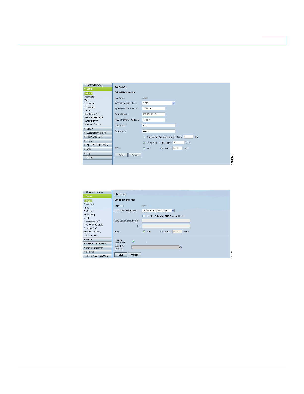
The Edit WAN Connection page appears after you click an Edit icon in the WAN
Settings section of the Network page. Enter the information provided by your ISP.
NOTE Before navigating away from this page, click Save to save your settings, or click
Cancel to undo them. Any unsaved changes are abandoned.
• Interface: The selected WAN port appears. This ID cannot be changed.
• WAN Connection Type: Choose a connection type, as described below.
- Obtain an IP Automatically: Choose this option if your ISP dynamically
assigns an IP address. For example, most cable modem subscribers use
this connection type. Your ISP will assign the settings, including the DNS
server IP address. If you want to specify a DNS server, check the Use
Cisco Small Business RV0xx Series Routers Administration Guide 34
Page 35

the Following DNS Server Addresses box. Then enter an IP address in
the DNS Server (Required) 1 box. Optionally, you can enter a second
DNS server. The first available DNS entry is used.
- Static IP: Choose this option if your ISP assigned a permanent IP
address to your account. Then enter the settings provided by your ISP:
Specify WAN IP Address: The external IP address that your ISP
assigned to your account.
Subnet Mask (IPv4): The subnet mask specified by your ISP.
Prefix Length (IPv6): The prefix length specified by your ISP.
Default Gateway Address: The IP address of the default gateway.
DNS Server (Required) 1: The IP address of the specified DNS server.
Optionally, enter a second DNS server. The first available DNS entry is
used.
3
- PPPoE (Point-to-Point Protocol over Ethernet): Choose this option if
your ISP uses PPPoE (Point-to-Point Protocol over Ethernet) to establish
Internet connections (typical for DSL lines). Then enter the settings
provided by your ISP:
Username and Password: Enter the username and password for your
ISP account. The maximum number of characters is 60.
Connect on Demand: This feature may be helpful if you are billed based
on the time that you are connected to the Internet. When this feature is
enabled, the connection will be disconnected after a specified period of
inactivity (Max Idle Time). As soon as you attempt to access the Internet
again, the router automatically re-establishes your connection. If you
enable this feature, also enter the Max Idle Time, which is number of
minutes that the connection can be inactive; when this limit is reached,
the connection is terminated. The default Max Idle Time is 5 minutes.
Keep Alive: This feature ensures that your router is always connected to
the Internet. When this feature is enabled, the router keeps the
connection alive by sending out a few data packets periodically. This
option keeps your connection active indefinitely, even when it sits idle. If
you enable this feature, also enter the Redial Period to specify how
often the router verifies your Internet connection. The default period is
30 seconds.
Cisco Small Business RV0xx Series Routers Administration Guide 35
Page 36

- PPTP (Point-to-Point Tunneling Protocol): Choose this option if
required by your ISP. PPTP is a service used in Europe, Israel, and other
countries.
Specify WAN IP Address: The external IP address that your ISP
assigned to your account.
Subnet Mask: The subnet mask specified by your ISP.
Default Gateway Address: The IP address of the default gateway.
Username and Password: Enter the username and password for your
ISP account. The maximum number of characters is 60.
Connect on Demand: This feature may be helpful if you are billed based
on the time that you are connected to the Internet. When this feature is
enabled, the connection will be disconnected after a specified period of
inactivity (Max Idle Time). As soon as you attempt to access the Internet
again, the router automatically re-establishes your connection. If you
enable this feature, also enter the Max Idle Time, which is number of
minutes that the connection can be inactive; when this limit is reached,
the connection is terminated. The default Max Idle Time is 5 minutes.
3
Keep Alive: This feature ensures that your router is always connected to
the Internet. When this feature is enabled, the router keeps the
connection alive by sending out a few data packets periodically. This
option keeps your connection active indefinitely, even when it sits idle. If
you enable this feature, also enter the Redial Period to specify how
often the router verifies your Internet connection. The default period is
30 seconds.
- Transparent Bridge: Choose this option if you are using this router to
connect two network segments. Only one WAN interface can be set as
transparent bridge.
Specify WAN IP Address: The external IP address that your ISP
assigned to your account.
Subnet Mask: The subnet mask specified by your ISP.
Default Gateway Address: The IP address of the default gateway.
DNS Server (Required) 1: The IP address of the specified DNS server.
Optionally, enter a second DNS server. The first available DNS entry is
used.
Internal LAN IP Range: The internal LAN IP range that will be bridged.
The WAN and LAN of transparent bridge will be at the same subnet.
Cisco Small Business RV0xx Series Routers Administration Guide 36
Page 37

3
• MTU: Set the MTU (Maximum Transmission Unit) in bytes (see the
Glossary). Unless a change is required by your ISP, Cisco recommends that
you use the default setting, Auto. To specify another value, select Manual,
and then enter the size in bytes.
• Enabled DHCP-PD: Check this box to enable the DHCPv6 client process
and enable a request for prefix delegation through the selected interface.
This option is typically used if your ISP is capable of sending LAN prefixes
via DHCPv6 option. If your ISP does not support this option, then you can
manually configure a LAN prefix by entering the LAN IPv6 address below.
Note: When DHCP-PD is enabled, the manual LAN IPv6 addressing below
will be disabled and vice versa.
• LAN IPv6 Address: This option allows you to manually enter a global IPv6
prefix that was assigned by your ISP for your LAN devices, if applicable.
Check with your ISP for more information.
Cisco Small Business RV0xx Series Routers Administration Guide 37
Page 38
3
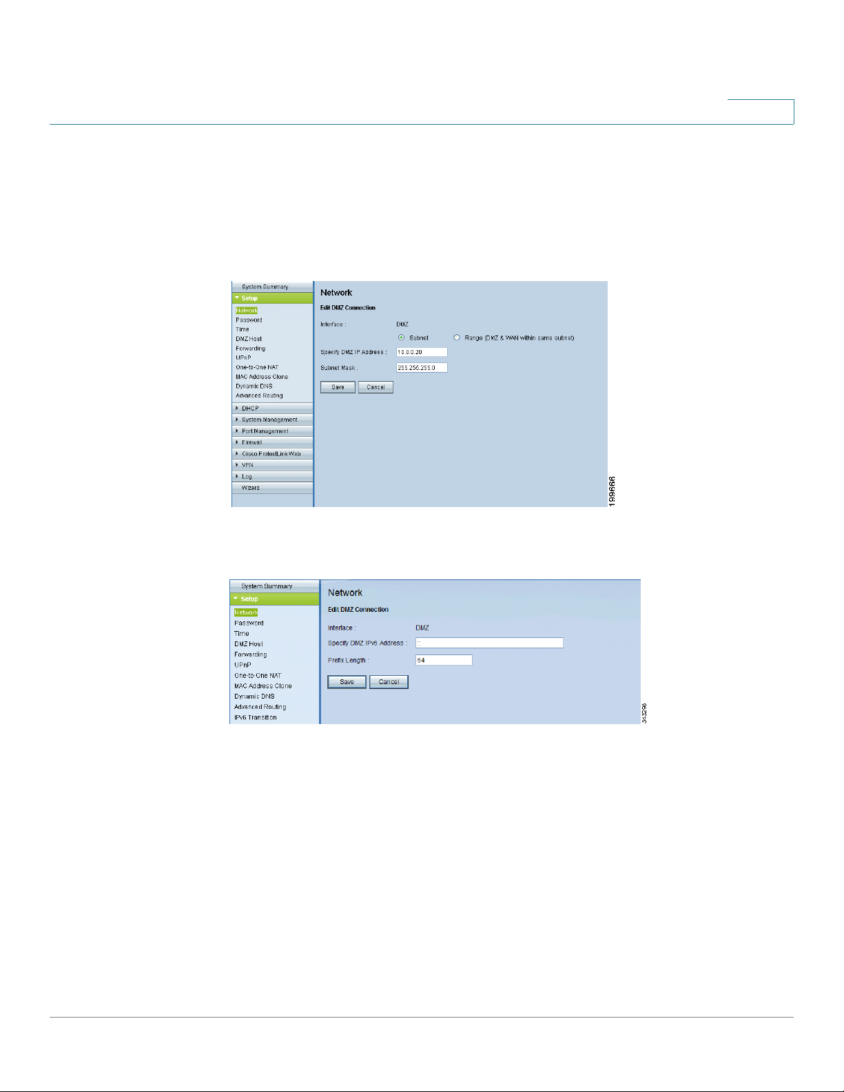
Editing a DMZ Connection
Use the Edit DMZ Connection page to specify the settings for your DMZ. DMZ is
enabled by default.
IPv4
IPv6
The Edit DMZ Connection page appears after you click the Edit icon in the DMZ
Setting section of the Network page.
NOTE Before navigating away from this page, click Save to save your settings, or click
Cancel to undo them. Any unsaved changes are abandoned.
If you are using IPv4 addressing, enter the following information:
• Subnet: Choose this option to place the DMZ on a different subnet than the
WAN (default setting). Enter an IP address and subnet mask for the DMZ.
• Range: Choose this option to place the DMZ on the same subnet as the
WAN. Enter the range of IP addresses to reserve for the DMZ port.
Cisco Small Business RV0xx Series Routers Administration Guide 38
Page 39

If you are using IPv6 addressing, enter the following information:
• Specify DMZ IPv6 Address: Enter an IPv6 address for the DMZ. Replace
the default double colon (::) with a valid IPv6 address for your DMZ.
• Prefix Length: Enter the prefix length. The default value is 64.
3
Cisco Small Business RV0xx Series Routers Administration Guide 39
Page 40
Setup
!
Changing the Administrator Username and Password
Changing the Administrator Username and Password
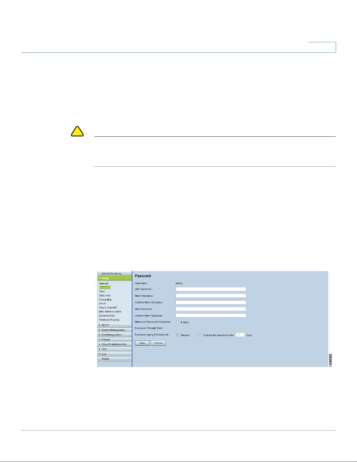
Use the Setup > Password page to update the administrator username and
password. You can keep the default username (admin) if you like. However, Cisco
strongly recommends changing the default password (admin) to a strong
password that is hard to guess.
CAUTION The password cannot be recovered if it is lost or forgotten. If the password is lost
or forgotten, you have to reset the router to its factory default settings. Doing so will
remove all of your configuration changes.
NOTE
3
• You must change the administrator password if you enable remote access
on the Firewall > General page.
• Before navigating away from this page, click Save to save your settings, or
click Cancel to undo them. After you change the username or password,
you will be required to log in with the new credentials when you select any
option in the navigation tree.
To open this page: Click Setup > Password in the navigation tree.
• Old Password: Enter the old password. The default password is admin.
• New Username: Enter a new username, if desired. To keep the existing
username, leave this field blank.
Cisco Small Business RV0xx Series Routers Administration Guide 40
Page 41

Setup
Changing the Administrator Username and Password
• Confirm New Username: To confirm, re-enter the new username, exactly
as shown in the previous field.
• New Password: Enter a new password for the router. You can include
alphanumeric characters and symbols, but no spaces.
• Confirm New Password: To confirm, re-enter the new password, exactly as
shown in the previous field. An error message appears if the passwords do
not match.
• Minimum Password Complexity: Check the Enable box if you want to
enforce password complexity and enable the Password Strength Meter.
This option is enabled by default and is recommended.
When Minimum Password Complexity is enabled, the password must meet
the requirements listed below. Your entries are validated when you click the
Save button.
3
- Includes at least 8 characters.
- Is not the same as the username.
- Is not the same as the current password.
- Contains characters from at least 3 of the following 4 categories:
uppercase letters, lowercase letters, numbers, and special characters
available on a standard keyboard.
• Password Strength Meter: If you enable Minimum Password Complexity,
the Password Strength Meter indicates the password strength, based on
the complexity rules. As you enter a password, colored bars appear. The
scale goes from red (unacceptable) to yellow (acceptable) to green (strong).
• Password Aging Enforcement: Choose Disable if you do not want the
password to expire. Choose Change the password after if you want the
password to expire after the specified number of Days (default 180).
Cisco Small Business RV0xx Series Routers Administration Guide 41
Page 42

Setup
Setting the System Time
Setting the System Time
Use the Setup > Time page to specify the system time for your network. The
router uses the time settings to time-stamp log events, to automatically apply the
Access Rules and Content Filters, and to perform other activities for other internal
purposes. You can allow the router to receive the local time settings automatically
from a server, or you can enter the local time manually.
To open this page: Click Setup > Time in the navigation tree.
3
NOTE Before navigating away from this page, click Save to save your settings, or click
Cancel to undo them. Any unsaved changes are abandoned.
Choose one of the following options to set the time, and then enter the required
information.
• Set the local time using Network Time Protocol (NTP) automatically:
Choose this option to allow the router to receive the time settings
automatically from an NTP server. Then enter the following settings:
- Time Zone: Select your time zone. The default is (GMT-08:00) Pacific
Time (US & Canada); Tijuana.
- Daylight Saving: To automatically adjust the time for daylight savings,
select Enabled. In the Start Date field, enter the Month and Day when
daylight savings time begins. Use mm.dd format, such as 6.25 for June
25. Also enter the End Date in the same format.
- NTP Server: Enter the URL or IP address of the NTP server. The default
is time.nist.gov.
Cisco Small Business RV0xx Series Routers Administration Guide 42
Page 43

Setup
Setting Up a DMZ Host
• Set the local time Manually: Choose this option if you want to set the local
time yourself. Then enter the following information:
- Date: Enter the current date in yyyy.mm.dd format, such as 2010.06.25
for June 25, 2010.
- Hours, Minutes, Seconds: Enter the current time in hh:mm:ss format,
such as 15:17:00 for 3:17:00 p.m.
Setting Up a DMZ Host
Use the Setup > DMZ Host page to allow one host in the LAN to be exposed to the
Internet to use services such as Internet gaming and video conferencing. Access
to the DMZ Host from the Internet can be further restricted by using firewall
access rules.
3
To open this page: Click Setup > DMZ Host in the navigation tree.
Enter the IP address of the network device that you want to use as a DMZ host.
NOTE Before navigating away from this page, click Save to save your settings, or click
Cancel to undo them. Any unsaved changes are abandoned.
Cisco Small Business RV0xx Series Routers Administration Guide 43
Page 44

Setup
Setting Up Port Forwarding and Port Triggering
Setting Up Port Forwarding and Port Triggering
3
Use the Setup >
on computers that are connected to the LAN ports. Port Forwarding opens a
specified port or a port range for a service, such as FTP. Port Triggering opens a
port range for services such as Internet gaming that use alternate ports to
communicate between the server and LAN host. This page has the following
sections:
• Port Range Forwarding, page 44
• Port Triggering, page 47
To open this page: Click Setup > Forwarding in the navigation tree.
Forwarding
page if you need to allow public access to services
NOTE Before navigating away from this page, click Save to save your settings, or click
Cancel to undo them. Any unsaved changes are abandoned.
Port Range Forwarding
Port forwarding can be used to set up public services on your network. When
users from the Internet make certain requests to your network, the router can
forward those requests to computers that are equipped to handle the requests. If,
for example, you set the port number 80 (HTTP) to be forwarded to IP address
192.168.1.2, then all HTTP requests from outside users will be forwarded to
192.168.1.2.
You may use this function to establish a web server or FTP server via an IP
gateway. Make sure that you enter a valid IP address. (You may need to establish a
static IP address in order to properly run an Internet server.) For added security,
Internet users will be able to communicate with the server, but they will not
actually be connected. The packets will simply be forwarded through the router.
Cisco Small Business RV0xx Series Routers Administration Guide 44
Page 45

Setup
Setting Up Port Forwarding and Port Triggering
• To add an entry to the list: Enter the following information, and then click
Add to list.
- Service: Select the service. If a service is not listed, you can add a
service. For details, see Adding a service, page 46.
- IP Address: Enter the LAN IP address of the server that you want the
Internet users to access.
- Enable: Check the box to enable this port range forwarding entry.
• To add another new entry: Enter the information, and then click Add to list.
• To modify an entry in the list: Click the entry that you want to modify. The
information appears in the text fields. Make the changes, and then click
Update. If you do not need to make changes, you can click Add New to deselect the entry and clear the text fields.
3
• To delete an entry from the list: Click the entry that you want to delete, and
then click Delete. To select a block of entries, click the first entry, hold down
the Shift key, and then click the final entry in the block. To select individual
entries, press the Ctrl key while clicking each entry. To de-select an entry,
press the Ctrl key while clicking the entry.
• To view the port range table: Click View, near the bottom of the page.
Choose Port Range Forwarding or Port Triggering. To update the display,
click Refresh. To return to the Forwarding page, click Close.
Cisco Small Business RV0xx Series Routers Administration Guide 45
Page 46

Setup
Setting Up Port Forwarding and Port Triggering
Adding a service
To add a new entry to the Service list, or to change an entry that you created
previously, click Service Management. If the web browser displays a warning
about the pop-up window, allow the blocked content.
3
In the Service Management window, add or update entries as needed. Before
closing this window, click OK to save your settings, or click Cancel to undo them.
Any unsaved changes are abandoned.
• To add a service to the list: Enter the following information, and then click
Add to List. You can have up to 30 services in the list.
- Service Name: Enter a short description.
- Protocol: Choose the required protocol. Refer to the documentation for
the service that you are hosting.
- Port Range: Enter the required port range.
• To add another new service: Enter the information, and then click Add to
list.
Cisco Small Business RV0xx Series Routers Administration Guide 46
Page 47

Setup
Setting Up Port Forwarding and Port Triggering
• To modify a service you created: Click the service in the list. The
information appears in the text fields. Make the changes, and then click
Update. If you do not need to make changes, you can click Add New to deselect the service and clear the text fields.
• To delete a service from the list: Click the entry that you want to delete. To
select a block of entries, click the first entry, hold down the Shift key, and
click the final entry in the block. To select individual entries, hold down the
Ctrl key while clicking. Click Delete.
Port Triggering
Port triggering allows the router to watch outgoing data for specified port
numbers. The IP address of the computer that sends the matching data is
remembered by the router, so that when the requested data returns through the
router, the data is transmitted to the proper computer by using IP address and port
mapping rules.
3
Some Internet applications or games use alternate ports to communicate between
the server and LAN host. When you want to use these applications, enter the
triggering (outgoing) port and alternate incoming port in the Port Triggering table.
Then the router will forward the incoming packets to the specified LAN host.
Add or edit entries as needed. Remember that the settings are not saved until you
click the Save button.
• To add an entry to the list: Enter the following information, and then click
Add to List. You can have up to 30 applications in the list.
- Application Name: Enter the name of the application.
- Trigger Port Range: Enter the starting and ending port numbers of the
trigger port range. Refer to the documentation for the application.
- Incoming Port Range: Enter the starting and ending port numbers of the
incoming port range. Refer to the documentation for the application.
- Enable: Check the box to enable port triggering for the application.
Uncheck the box to disable the application.
• To add another new entry: Enter the information, and then click Add to list.
• To modify an entry in the list: Click the entry that you want to modify. The
information appears in the text fields. Make the changes, and then click
Update. If you do not need to make changes, you can click Add New to deselect the entry and clear the text fields.
Cisco Small Business RV0xx Series Routers Administration Guide 47
Page 48
Setup
Setting Up Universal Plug and Play (UPnP)
• To delete an entry from the list: Click the entry that you want to delete, and
then click Delete. To select a block of entries, click the first entry, hold down
the Shift key, and then click the final entry in the block. To select individual
entries, press the Ctrl key while clicking each entry. To de-select an entry,
press the Ctrl key while clicking the entry.
• To view the port range table: Click View, near the bottom of the page.
Choose Port Range Forwarding or Port Triggering. To update the display,
click Refresh. To return to the Forwarding page, click Close.
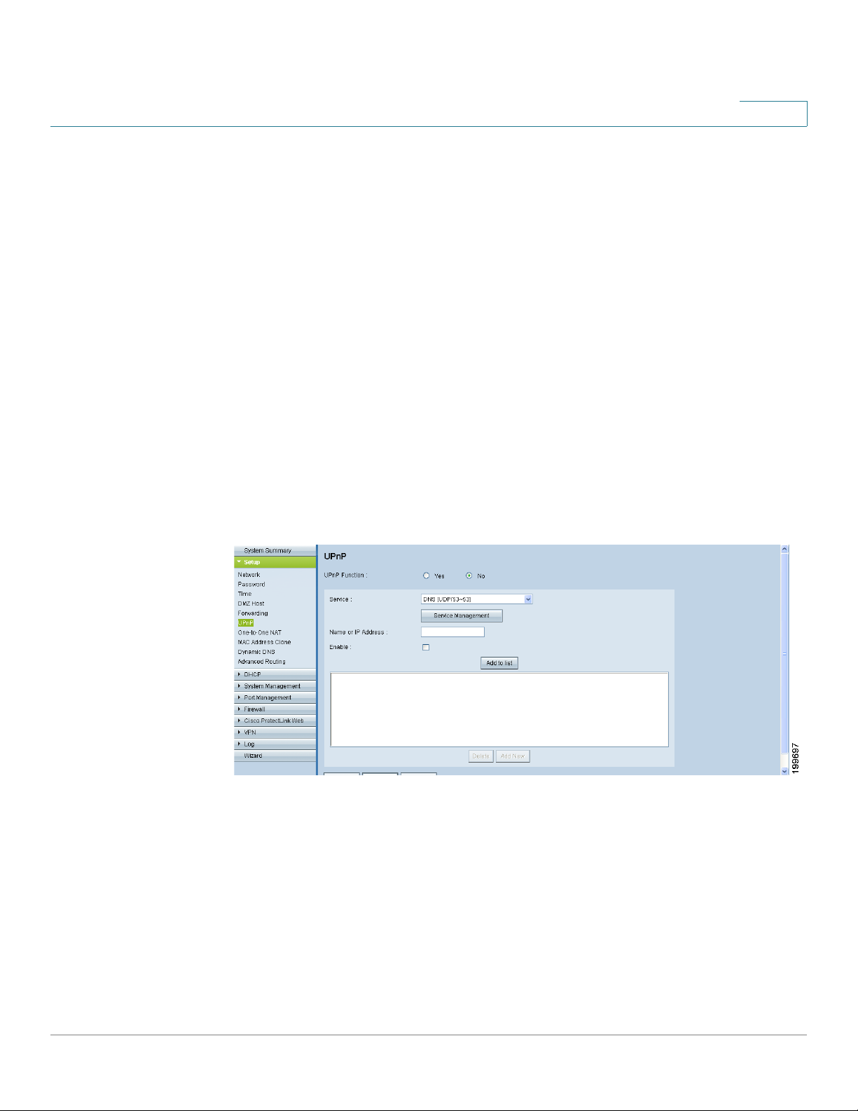
Setting Up Universal Plug and Play (UPnP)
Use the Setup > UPnP page to enable Universal Plug and Play (UPnP). This feature
allows Windows to automatically configure the router to open and close ports for
Internet applications such as gaming and videoconferencing.
3
NOTE
To open this page: Click Setup > UPnP in the navigation tree.
• As a security precaution, disable UPnP unless you require it for your
applications.
• Before navigating away from this page, click Save to save your settings, or
click Cancel to undo them. Any unsaved changes are abandoned.
Cisco Small Business RV0xx Series Routers Administration Guide 48
Page 49
Setup
Setting Up Universal Plug and Play (UPnP)
To e n a b l e U P n P, c l i c k Ye s. To disable this feature, click No. Add or edit entries as
needed.
• To add an entry to the list: Enter the following information, and then click
Add to List. You can have up to 30 services in the list.
- Service: Select the service. If a service is not listed, you can add a
service. See Adding a service, page 50.
- Name or IP Address: Enter the name or IP address of the UPnP device.
- Enable: Select Enable to enable this UPnP entry.
• To add another new entry: Enter the information, and then click Add to list.
• To modify an entry in the list: Click the entry that you want to modify. The
information appears in the text fields. Make the changes, and then click
Update. If you do not need to make changes, you can click Add New to deselect the entry and clear the text fields.
3
• To delete an entry from the list: Click the entry that you want to delete, and
then click Delete. To select a block of entries, click the first entry, hold down
the Shift key, and then click the final entry in the block. To select individual
entries, press the Ctrl key while clicking each entry. To de-select an entry,
press the Ctrl key while clicking the entry.
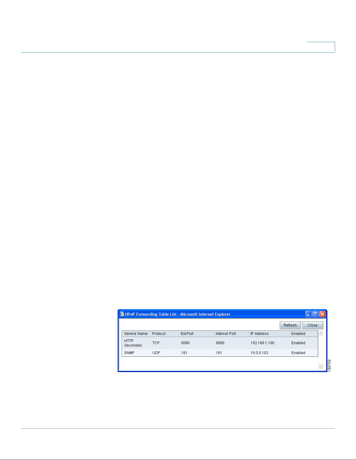
The UPnP Forwarding Table List displays the current data. You can click
Refresh to update the data, or click Close to close the pop-up window.
• To view the UPnP forwarding table: Click View, near the bottom of the
page. To update the display, click Refresh. To return to the UPnP page,
click Close.
Cisco Small Business RV0xx Series Routers Administration Guide 49
Page 50

Setup
Setting Up Universal Plug and Play (UPnP)
Adding a service
To add a new entry to the Service list, or to change an entry that you created
previously, click Service Management. If the web browser displays a warning
about the pop-up window, allow the blocked content.
3
In the Service Management window, add or update entries as needed. Before
closing this window, click OK to save your settings, or click Cancel to undo them.
Any unsaved changes are abandoned.
• To add a service to the list: Enter the following information, and then click
Add to List. You can have up to 30 services in the list.
- Service Name: Enter a short description.
- Protocol: Choose the required protocol. Refer to the documentation for
the service that you are hosting.
- Port Range: Enter the required port range.
• To add another new service: Enter the information, and then click Add to
list.
Cisco Small Business RV0xx Series Routers Administration Guide 50
Page 51
Setup
Setting Up One-to-One NAT
• To modify a service you created: Click the service in the list. The
information appears in the text fields. Make the changes, and then click
Update. If you do not need to make changes, you can click Add New to deselect the service and clear the text fields.
• To delete a service from the list: Click the entry that you want to delete. To
select a block of entries, click the first entry, hold down the Shift key, and
click the final entry in the block. To select individual entries, hold down the
Ctrl key while clicking. Click Delete.
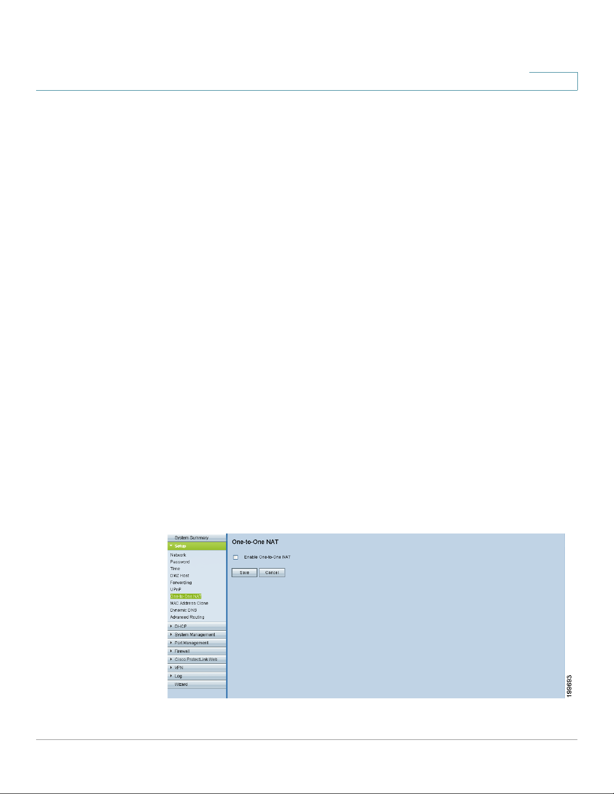
Setting Up One-to-One NAT
Use the Setup > One-to-One NAT page to enable One-to-One NAT (Network
Address Translation). This process creates a relationship that maps a valid
external IP address to an internal IP address that is hidden by NAT. Traffic can then
be routed from the Internet to the specified internal resource.
3
NOTE For best results, reserve IP addresses for the internal resources that you want to
reach through one-to-one NAT. See About Static IP Addresses (for IPv4 Only),
page 66.
You can map a single relationship, or map an internal IP address range to an
external range of equal length (for example, three internal addresses and three
external addresses). The first internal address is mapped to the first external
address, the second IP internal IP address is mapped to the second external
address, and so on.
To open this page: Click Setup > One-to-One NAT in the navigation pane.
Cisco Small Business RV0xx Series Routers Administration Guide 51
Page 52

Setup
Setting Up One-to-One NAT
NOTE Before navigating away from this page, click Save to save your settings, or click
3
Cancel to undo them. Any unsaved changes are abandoned.
To enable this feature, check the Enable One-to-One NAT box. Add or edit entries
as needed.
• To add an entry to the list: Enter the following information, and then click
Add to List.
- Private Range Begin: Enter the starting IP address of the internal IP
address range that you want to map to the public range. Do not include
the router’s LAN IP address in this range.
- Public Range Begin: Enter the starting IP address of the public IP
address range provided by the ISP. Do not include the router’s WAN IP
address in this range.
- Range Length: Enter the number of IP addresses in the range. The range
length cannot exceed the number of valid IP addresses. To map a single
address, enter 1.
• To add another new entry: Enter the information, and then click Add to list.
• To modify an entry in the list: Click the entry that you want to modify. The
information appears in the text fields. Make the changes, and then click
Update. If you do not need to make changes, you can click Add New to deselect the entry and clear the text fields.
• To delete an entry from the list: Click the entry that you want to delete, and
then click Delete. To select a block of entries, click the first entry, hold down
the Shift key, and then click the final entry in the block. To select individual
entries, press the Ctrl key while clicking each entry. To de-select an entry,
press the Ctrl key while clicking the entry.
Cisco Small Business RV0xx Series Routers Administration Guide 52
Page 53

Setup
Cloning a MAC Address for the Router
Cloning a MAC Address for the Router
Some ISPs require that you register a MAC address, which is a 12-digit code
assigned to a unique piece of hardware for identification. If you previously
registered another MAC address with your ISP, you can use the Setup > MAC
Address Clone page to “clone” that address to your Cisco RV0xx Series router. By
using this process, you don’t have to call your ISP to change the registered MAC
address.
To open this page: Click Setup > MAC Address Clone in the navigation tree.
3
This page displays the current settings. Click the Edit icon to display the Edit MAC
Address Clone page. For more information, see Editing the MAC Address Clone
Settings, page 54.
Cisco Small Business RV0xx Series Routers Administration Guide 53
Page 54
3
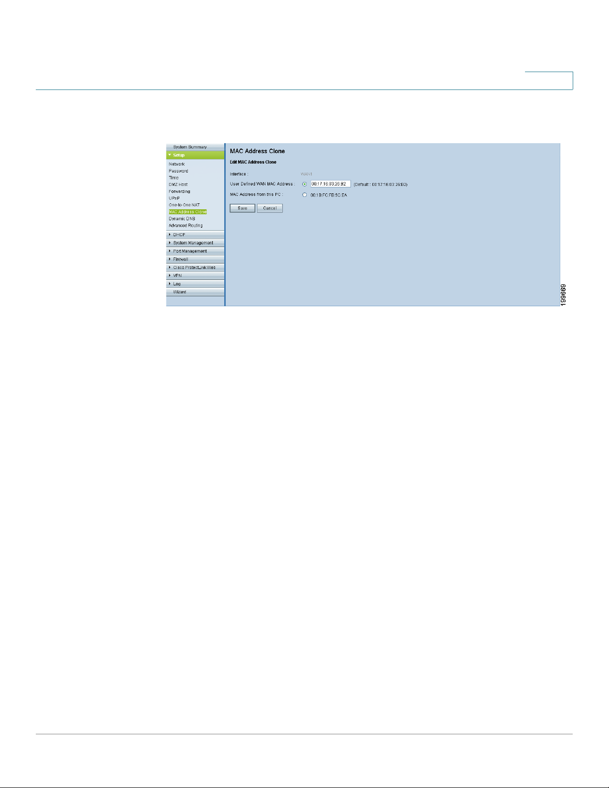
Editing the MAC Address Clone Settings
The Edit MAC Address Clone page appears after you click the Edit icon on the
MAC Address Clone page.
NOTE Before navigating away from this page, click Save to save your settings, or click
Cancel to undo them. Any unsaved changes are abandoned.
To clone a MAC address, enter the following settings.
• User Defined WAN MAC Address: To manually clone a MAC address, click
the radio button, and then enter the 12 digits of the MAC address that you
registered with your ISP.
• MAC Address from this PC: To clone the MAC address of the computer
you are currently using to configure the router, click this radio button. The
MAC address of your PC is displayed automatically.
Cisco Small Business RV0xx Series Routers Administration Guide 54
Page 55
Assigning a Dynamic DNS Host Name to a WAN Interface
Assigning a Dynamic DNS Host Name to a WAN Interface
Dynamic Domain Name System (DDNS) service allows you to assign a fixed
domain name to a dynamic WAN IP address, so you can host your own web, FTP
or other type of TCP/IP server in your LAN. Use the Setup > Dynamic DNS page to
configure the WAN interfaces with your Dynamic DNS information.
Before configuring Dynamic DNS on the router, you need to visit www.dyndns.org
and register a domain name. (The service is provided by DynDNS.org). For users in
China, visit www.3322.org to register.
To open this page: Click Setup > Dynamic DNS in the navigation tree.
3
NOTE Before navigating away from this page, click Save to save your settings, or click
Cancel to undo them. Any unsaved changes are abandoned.
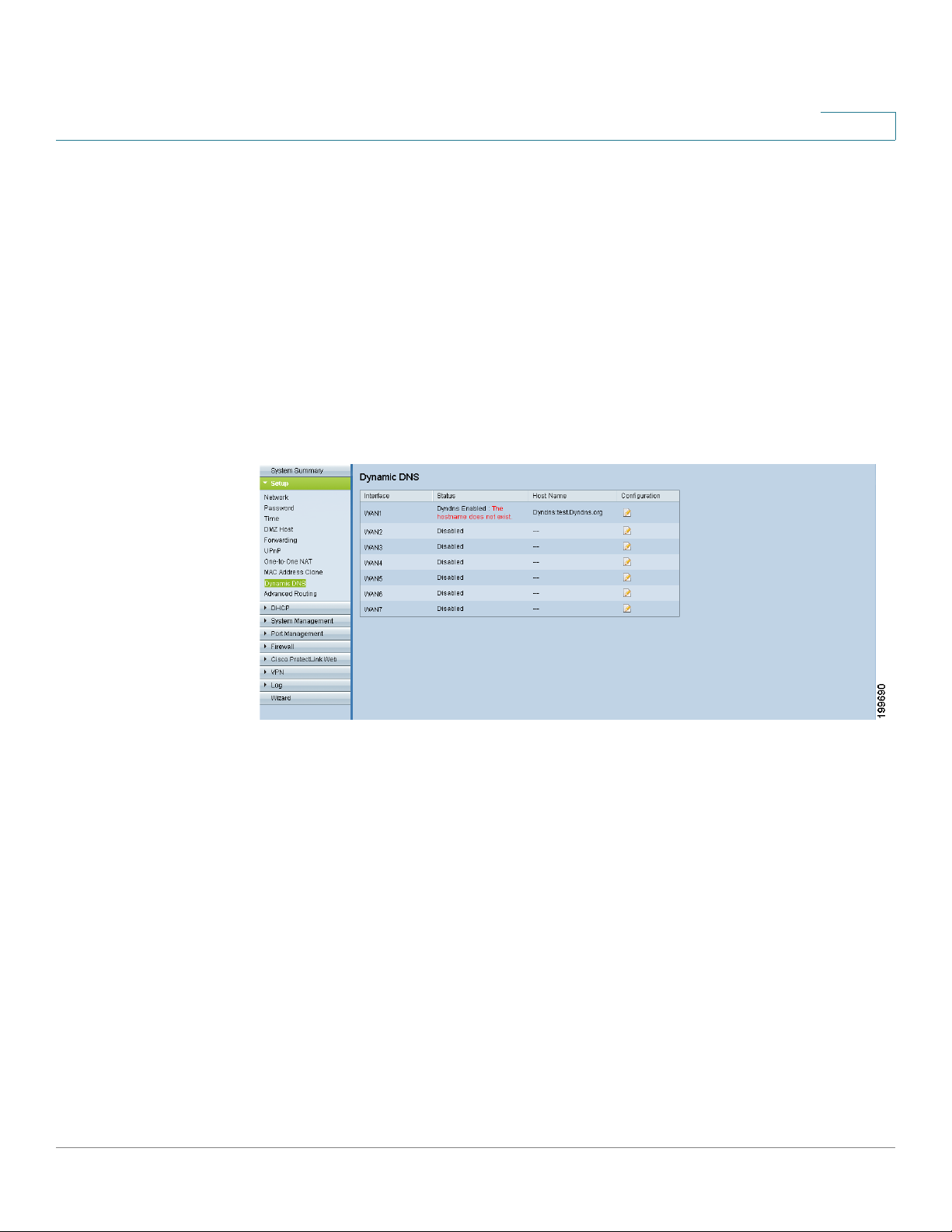
This page displays the current settings. Click the Edit icon for the WAN interface to
display the Edit Dynamic DNS Setup page. For more information, see Editing the
Dynamic DNS Setup, page 56.
Cisco Small Business RV0xx Series Routers Administration Guide 55
Page 56
3
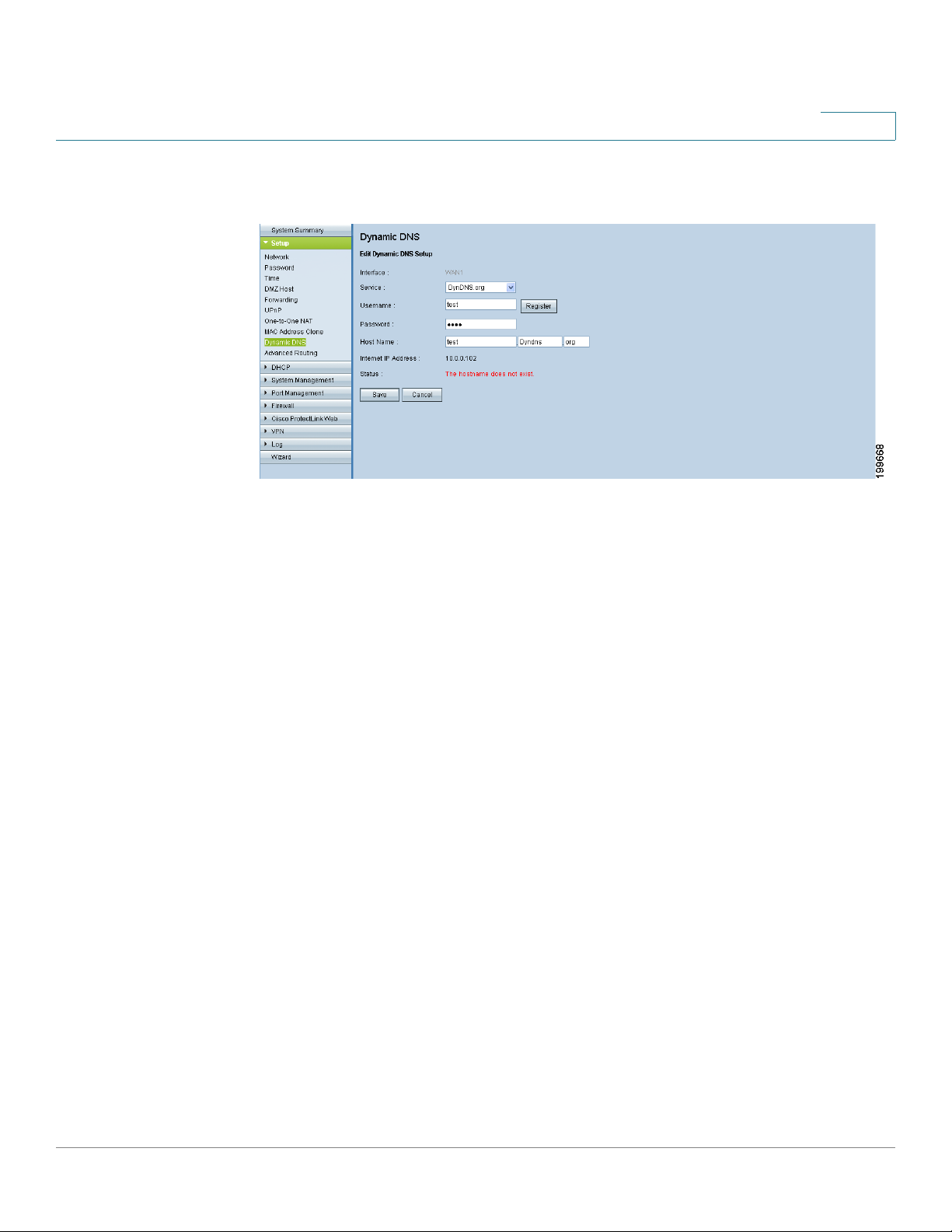
Editing the Dynamic DNS Setup
The Edit Dynamic DNS Setup page appears after you click an Edit icon on the
Dynamic DNS page.
NOTE Before navigating away from this page, click Save to save your settings, or click
Cancel to undo them. Any unsaved changes are abandoned.
From the DDNS Service list, choose your service. Then enter the information for
your account, as described below. To disable this feature, choose Disable.
• Username: Enter the username for your DDNS account.
If you have not previously registered a host name, you can click Register to
go to the DynDNS.com website, where you can sign up for free Dynamic
DNS service. Click the Sign up FREE link, and then continue through all of
the steps.
• Password: Enter the password for your DDNS account.
• Host Name: Use these three fields to enter the host name that you
registered with your DDNS provider. For example, if your host name is
myhouse.dyndns.org, then enter myhouse in the first field, dyndns in the
second field, and org in the last field.
The following read-only information appears:
• Internet IP Address: The current WAN IP address for the interface.
Because it is dynamic, this setting will change.
• Status: The status of the DDNS function. If the status information indicates
an error, make sure you have correctly entered the information for your
account with your DDNS service.
Cisco Small Business RV0xx Series Routers Administration Guide 56
Page 57
Setting Up Advanced Routing
Setting Up Advanced Routing
3
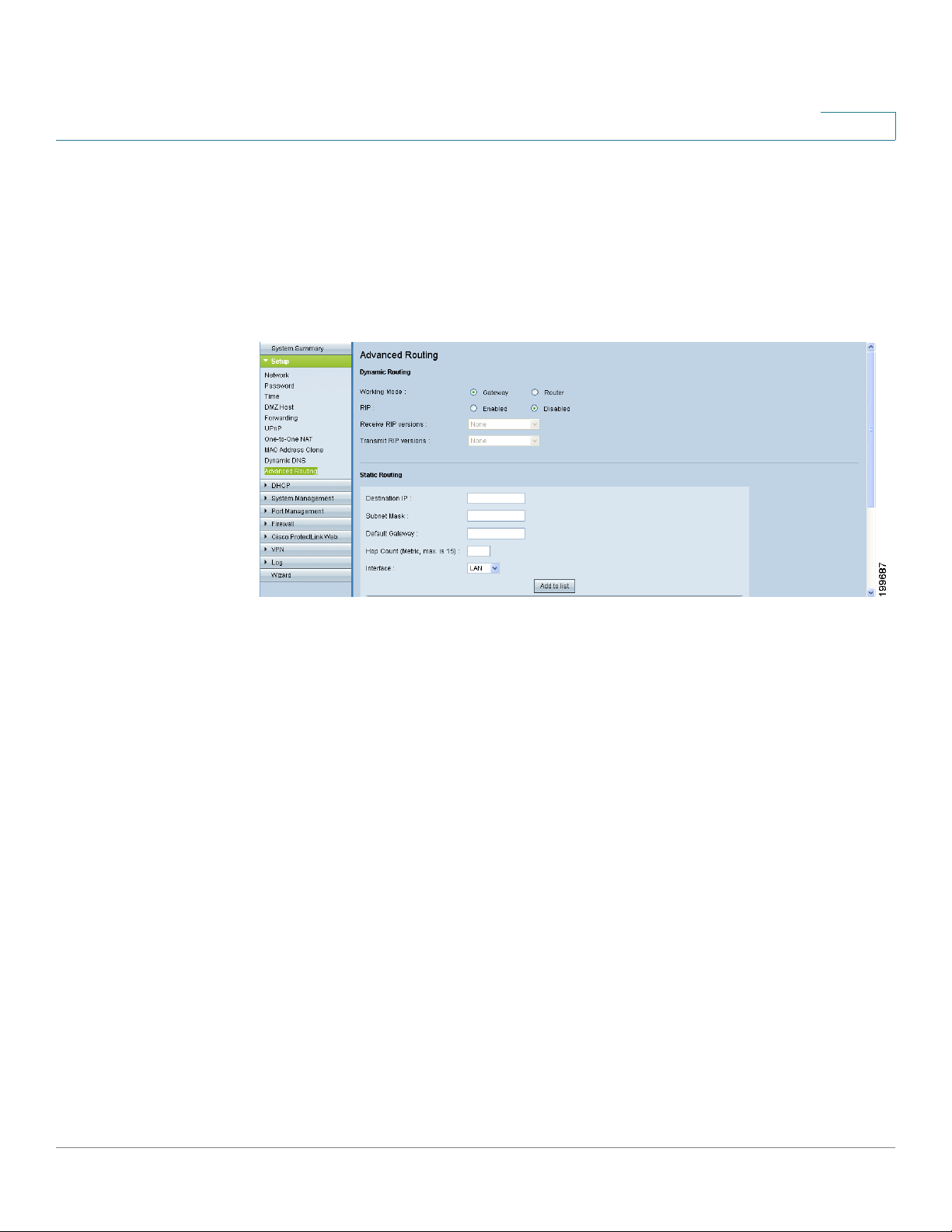
Use the Setup >
routing settings and to view current routing information.
To open this page: Click Setup > Advanced Routing in the navigation tree.
NOTE Before navigating away from this page, click Save to save your settings, or click
Cancel to undo them. Any unsaved changes are abandoned.
Perform the following tasks:
Advanced Routing
page to configure the dynamic and static
• To configure static or dynamic routing: Click the IPv4 or IPv6 tab, and
then enter the settings. See these topics:
- Configuring Dynamic Routing, page 58
- Configuring Static Routing, page 59
• To view current data: Click View near the bottom of the page. The Routing
Tab le En t r y L is t appears. You can click Refresh to update the data, or click
Close to close the pop-up window.
Cisco Small Business RV0xx Series Routers Administration Guide 57
Page 58

Setting Up Advanced Routing
3
Configuring Dynamic Routing
Enter the settings for dynamic routing by using Routing Information Protocol
(RIP) (see the glossary for more information).
Dynamic Routing for IPv4:
Click the IPv4 tab, and then enter the settings described below.
• Working Mode: Choose one of the following options.
- Gateway: Choose this mode if the router is hosting your network’s
connection to the Internet. This is the default setting.
- Router: Choose this mode if the router exists on a network with other
routers, and another router acts as the network gateway to the Internet.
In Router mode, Internet connectivity is available only if you have another
router that functions as the Gateway. Since firewall protection is
provided by the gateway router, disable this router’s firewall. See
Configuring the General Firewall Settings, page 99.
• RIP: Routing Information Protocol allows a router to exchange its routing
information automatically with other routers, and to dynamically adjust its
routing tables as network changes occur. RIP prevents routing loops by
using a hop limit. To enable this option, select Enabled. Otherwise, keep the
default setting, Disabled. If you enable this feature, also configure the
following settings:
• Receive RIP versions: Select the RIP protocol for receiving network data:
None, RIPv1, RIPv2, or Both RIP v1 and v2.
RIPv1 is a class-based routing version. It does not include subnet
information and therefore does not support variable length subnet masks
(VLSM). RIPv1 also lacks support for router authentication, making it
vulnerable to attacks. RIPv2 carries a subnet mask and supports password
authentication security.
• Transmit RIP versions: Select the RIP protocol for transmitting network
data: None, RIPv1, RIPv2 - Broadcast, or RIPv2 - Multicast.
RIPv2 - Broadcast (recommended) broadcasts data in the entire subnet.
RIPv2 - Multicast sends data to multicast addresses. RIPv2 - Multicast also
helps to avoid unnecessary load by multicasting routing tables to adjacent
routers rather than broadcasting to the entire network.
Cisco Small Business RV0xx Series Routers Administration Guide 58
Page 59

Setting Up Advanced Routing
NOTE The IPv6 tab is available if you enabled Dual-Stack IP on the Setup > Network page.
WARNING Static routing is an advanced feature. Create these routes with care.
3
Dynamic Routing for IPv6:
Check the box to enable RIPng (RIP next generation), or uncheck the box to
disable it. (See the Glossary for more information.)
Configuring Static Routing
Enter the settings for static routing (see the Glossary for more information).
Add or edit entries as needed. Remember that the settings are not saved until you
click the Save button.
• To add a new static route: Enter the following settings, and then click Add
to List. You can enter up to 30 routes.
- Destination IP: Enter the network address of the remote LAN segment.
For a standard Class C IP domain, the network address is the first three
fields of the Destination LAN IP, while the last field should be 0.
- Subnet Mask (IPv4 only): Enter the subnet mask used on the
destination LAN IP domain. For Class C IP domains, the subnet mask is
255.255.255.0.
- Prefix Length (Pv6 only): Enter the prefix length.
- Default Gateway: Enter the IP address of the router of the network, for
which this static route is created. For example, if this network is
connected to the local router’s LAN port through another router, use the
WAN IP address of that router.
- Hop Count: Enter the appropriate value (maximum is 15). This indicates
the number of nodes that a data packet passes through before reaching
its destination. A node is any device on the network, such as a computer
or router.
- Interface: Select the interface to use for this route. Select a WAN
interface if this router provides Internet connectivity for your network.
Select LAN if this router gets Internet connectivity from a gateway router
on your LAN.
Cisco Small Business RV0xx Series Routers Administration Guide 59
Page 60

Setting Up Advanced Routing
3
• To add another new static route: Enter the information, and then click Add
to list.
• To modify a static route in the list: Click the entry that you want to modify.
The information appears in the text fields. Make the changes, and then click
Update. If you do not need to make changes, you can click Add New to deselect the entry and clear the text fields.
• To delete an entry from the list: Click the entry that you want to delete, and
then click Delete. To select a block of entries, click the first entry, hold down
the Shift key, and then click the final entry in the block. To select individual
entries, press the Ctrl key while clicking each entry. To de-select an entry,
press the Ctrl key while clicking the entry.
• To view current data: Click View near the bottom of the page. The Routing
Tab le En t r y L is t appears. You can click Refresh to update the data, or click
Close to close the pop-up window.
Cisco Small Business RV0xx Series Routers Administration Guide 60
Page 61

IPv6 Transition
IPv6 Transition
3
When Dual-Stack IP is enabled on the Network > Setup page, a 6to4 tunnel is
enabled by default for IPv6 packets via 6to4 source/destination addressing
exchange. This feature allows the router to establish auto-tunnel in IPv4 network
(or a real IPv4 Internet connection) across two independent IPv6 networks. Use
the Setup > IPv6 Transition page to disable or enable this feature.
To open this page: Click Setup > IPv6 Transition in the navigation tree.
Check the box to enable the 6to4 tunnel, or uncheck the box to disable it.
NOTE Before navigating away from this page, click Save to save your settings, or click
Cancel to undo them. Any unsaved changes are abandoned.
Next steps: For a typical deployment, such as setting up a 6to4 tunnel between
your RV0xx Series router and a Cisco RV Series router at another site, you also
should complete the tasks listed below.
• On the DHCP->Router Advertisement page, enable managed RA flags to
support auto-configuration of connected devices. Verify that your IPv6
devices acquire 6to4 prefixes. The prefixes will be in the following format:
2002:<your WAN IP in hexadecimal format>::)
• Temporarily disable the router firewall for testing of your 6to4 tunnel. On the
Firewall > General page, choose Disable. To test the tunnel, attempt to ping
an IPv6 address at the remote location.
• After verifying the tunnel as described above, enable the firewall and add
access rules on the Firewall > Access Rules page. For example, add a rule
to allow all traffic through the WAN interface where the source is a single IP
Cisco Small Business RV0xx Series Routers Administration Guide 61
Page 62

IPv6 Transition
3
address or a range of addresses on the local network and the destination is
a single IP address or a range of addresses on the remote network.
• Complete the required tasks on the router at the other end of the 6to4
tunnel.
NOTE For detailed application notes, see the documentation links in Appendix H, “Where
to Go From Here.”
Cisco Small Business RV0xx Series Routers Administration Guide 62
Page 63

DHCP
4
Use the DHCP module to configure the settings for the DHCP server or DHCP
relay agent, and to view DHCP summary information.
If Dual-Stack IP is enabled on the Network > Setup page, you can configure IPv4
and IPv6 settings.
Refer to these topics:
• Setting Up the DHCP Server or DHCP Relay, page 63
• Viewing the DHCP Status Information, page 70
• Router Advertisement (IPv6), page 71
Setting Up the DHCP Server or DHCP Relay
Use the DHCP > DHCP Setup page to configure this router as a DHCP (Dynamic
Host Configuration Protocol) server or as a DHCP relay agent.
A DHCP server automatically assigns available IP addresses to computers on your
network. An address is “leased” to a client for a specified time, and then it expires
and can be assigned to a different device. If a device needs to have an unchanging
IP addresses, you can add the device to the Static IP list. Optionally, you can use
the Static IP list to block access by devices that are not on the list or do not have
the correct IP address.
If you have another DHCP server on your network, or if you want to assign IP
addresses manually, you can disable the DHCP feature and enable DHCP Relay.
For more information, see Enabling DHCP Server and DHCP Relay, page 64.
NOTE DHCP Relay is available only on the IPv4 tab. DHCPv6 Relay is not available.
Cisco Small Business RV0xx Series Routers Administration Guide 63
Page 64
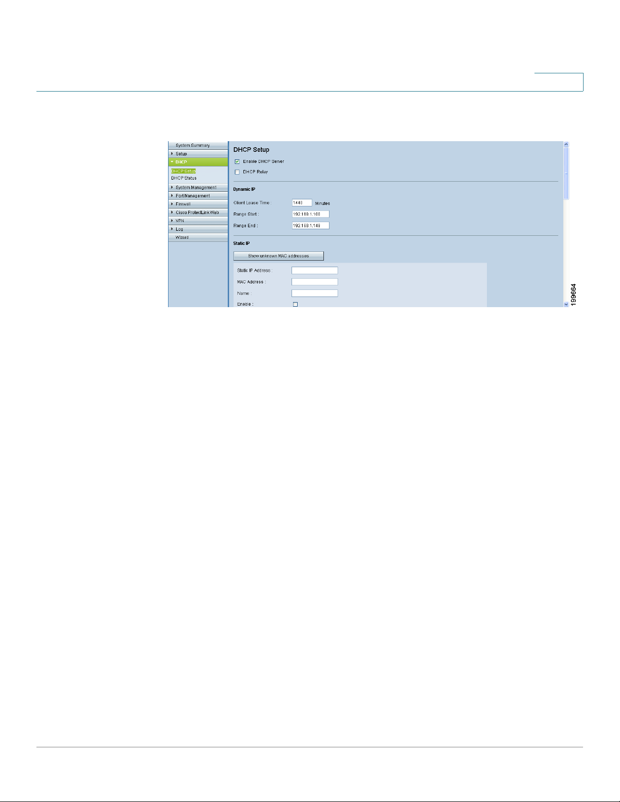
DHCP
Setting Up the DHCP Server or DHCP Relay
To open this page: Click DHCP > DHCP Setup in the navigation tree.
NOTE Before navigating away from this page, click Save to save your settings, or click
Cancel to undo them. Any unsaved changes are abandoned.
4
Enabling DHCP Server and DHCP Relay
Click the IPv4 tab or the IPv6 tab.
Note: The IPv6 tab is available only if you enabled Dual-Stack IP on the Network >
Setup page.
Enter the following settings:
• Enable DHCP server: Check the box to allow the router to dynamically
assign IP addresses to up to 50 connected devices. Uncheck the box if you
have another DHCP server on the network or you want to configure static IP
addresses for your network devices. If you enable this feature, enter the
settings in the Dynamic IP section of the page, as described below. Other
sections of this page are optional.
• DHCP Relay (IPv4 only): If you have another DHCP server, enable DHCP
Relay to allow this router to communicate the clients’ DHCP requests to the
DHCP server. The DHCP Relay mechanism allows the DHCP clients and the
DHCP server to be located on different networks. The DHCP clients will
send DHCP discover broadcast packets to get IP addresses from the DHCP
server. This router will act as DHCP Relay agent and send DHCP unicasts to
DHCP server.
Required: Enter the DHCP Server IP Address. Other sections of this page
are optional.
Cisco Small Business RV0xx Series Routers Administration Guide 64
Page 65

DHCP
Setting Up the DHCP Server or DHCP Relay
NOTE IPv4 only: If you disable both DHCP server and DHCP Relay, configure each device
on your network with a static IP address, subnet mask, and DNS settings. Do not
assign the same IP address to different computers.
Dynamic IP (used for DHCP Server only)
• Client Lease Time: The Client Lease Time is the amount of time that a
network user is allowed to connect to the router with the current dynamic IP
address. Enter the amount of time in minutes. Valid values are 5~43,200
minutes. The default is 1440 minutes, which is 24 hours.
NOTE: To receive an IP address from the DHCP server, a client device must
be configured to obtain an IP address automatically from a DHCP server. By
default, Windows computers are set to obtain an IP automatically.
• Range Start and Range End: Enter a starting IP address and an ending IP
address to create a range of IP addresses that can be assigned
dynamically. The range can include up to 50 IP addresses, which is the
maximum that the server can assign. Valid values are 100~149. Do not
include the router’s LAN IP address in this dynamic IP range. For example, if
the router uses the default LAN IP address, 192.168.1.1, then the starting
value must be 192.168.1.2 or greater.
4
DNS (used for DHCP Server only)
Optionally, enter the IP address of a DNS Server. You also can enter a secondary
DNS server. Specifying a DNS server can provide quicker access than using a
DNS server that is dynamically assigned through the WAN settings. You can keep
the default setting of 0.0.0.0 to use a dynamically assigned DNS server.
WINS (used for DHCP Server, IPv4 Only)
Optionally, enter the IP address of a WINS Server. Windows Internet Naming
Service resolves NetBIOS names to IP addresses. If you do not know the IP
address of the WINS server, keep the default, 0.0.0.0.
NOTE To support NetBIOS for DHCP clients, the router uses two methods:
• When the DHCP clients receive dynamic IP addresses from the router, it
automatically includes the information of the WINS server to support
NetBIOS.
• If a client has a static IP address, then the IP address, subnet mask, default
gateway address, and DNS server settings must be configured on the
Internet Protocol (TCP/IP) page of the Windows operating system. Then the
WINS IP address must be configured on the advanced TCP/IP page. (For
more information, refer to Windows Help.)
Cisco Small Business RV0xx Series Routers Administration Guide 65
Page 66
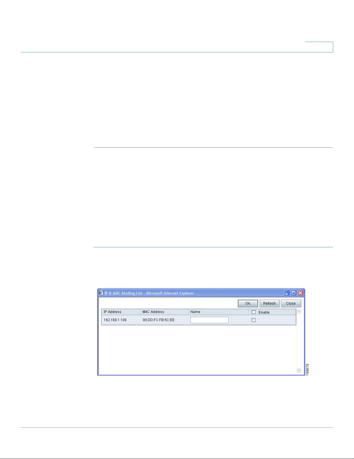
DHCP
Setting Up the DHCP Server or DHCP Relay
About Static IP Addresses (for IPv4 Only)
When DHCP is enabled, you may wish to assign static IP addresses to certain
devices, such as a web server or an FTP server. You can add up to 100 devices to
the Static IP list.
TIP Ensure that each of these devices is configured to use a static IP address. For
example, on a Windows computer, open the Local Area Connection Properties,
select Internet Protocol (TCP/IP), and then click the Properties button. Choose
Use the following IP address, and enter the IP address, subnet mask, and default
gateway (the router IP address). Optionally, enter a preferred DNS server.
Choose devices from a list or enter the device IP addresses and MAC addresses
manually.
• Assigning static IP addresses by adding devices from a list, page 66
4
• Assigning static IP addresses by entering devices manually, page 67
• Using the Static IP List to Block Devices, page 68
NOTE You can use this feature even if the router is not the DHCP server.
Assigning static IP addresses by adding devices from a list
STEP 1 Click Show unknown MAC addresses. The IP & MAC binding list appears. If the
web browser displays a message about the pop-up window, allow the blocked
content.
Cisco Small Business RV0xx Series Routers Administration Guide 66
Page 67

DHCP
Setting Up the DHCP Server or DHCP Relay
The devices are listed by the IP address and the MAC address. (Typically the MAC
address appears on a label on the bottom panel or back panel of a device.) If
needed, you can click Refresh to update the data.
STEP 2 To select a device, first enter a descriptive Name. Then check the Enable box.
Alternatively, select all devices in the list by clicking the check box at the top of the
Enable column.
STEP 3 Click OK to add the devices to the Static IP list, or click Close to close the pop-up
window without adding the selected devices. After you click OK, a message
appears. The message includes important information. Read it before clicking OK.
Keep the browser open and wait until the selected MAC addresses appear in the
Static IP list.
STEP 4 Modify or remove list entries, as needed:
• To m od if y th e s et tin gs: Click a device in the list. The information appears in
the text fields. Make the changes, and then click Update. If you do not need
to make changes, you can click Add New to de-select the entry and clear the
text fields.
4
• To delete an entry from the list: Click the entry that you want to delete, and
then click Delete. To select a block of entries, click the first entry, hold down
the Shift key, and then click the final entry in the block. To select individual
entries, press the Ctrl key while clicking each entry. To de-select an entry,
press the Ctrl key while clicking the entry.
Assigning static IP addresses by entering devices manually
In the Static IP Address section, add or edit entries as needed. Remember that the
settings are not saved until you click the Save button.
• To add a new device to the list: Enter the following information, and then
click Add to list.
- Static IP Address: Enter the static IP address. You can enter 0.0.0.0 if
you want the router to assign a static IP address to the device.
- MAC Address: Enter the MAC address of the device. (Typically the MAC
address appears on a label on the bottom panel or the back panel of a
device.) Enter the address without punctuation.
- Name: Enter a descriptive name for the device.
- Enable: Check this box to assign the static IP address to this device.
• To add another new entry: Enter the information, and then click Add to list.
Cisco Small Business RV0xx Series Routers Administration Guide 67
Page 68

DHCP
Setting Up the DHCP Server or DHCP Relay
• To m od if y th e s et tin gs: Click a device in the list. The information appears in
the text fields. Make the changes, and then click Update. If you do not need
to make changes, you can click Add New to de-select the entry and clear
the text fields.
• To delete an entry from the list: Click the entry that you want to delete, and
then click Delete. To select a block of entries, click the first entry, hold down
the Shift key, and then click the final entry in the block. To select individual
entries, press the Ctrl key while clicking each entry. To de-select an entry,
press the Ctrl key while clicking the entry.
Using the Static IP List to Block Devices
You can use the Static IP list to control access to your network. You can block
access by devices that are not on the list or do not have the correct IP address.
4
STEP 1 Add devices to the Static IP list as described in About Static IP Addresses (for
IPv4 Only), page 66.
STEP 2 Enable or disable the following features:
• Block MAC address on the list with wrong IP address: Check this box to
prevent a computer from accessing your network if its IP address has been
changed. For example, if you previously assigned a static IP address of
192.168.1.100 and someone configures the device to use 192.168.149, the
device will not be allowed to connect to your network. This feature
discourages users from changing their device IP addresses without your
permission. Uncheck the box to allow access regardless of the current IP
address assignment.
• Block MAC address not on the list: Check this box to block access from
devices that are not included in the Static IP list. This feature prevents
unknown devices from accessing your network. Uncheck the box to allow
access by any connected device that is configured with an IP address in
the correct range.
Cisco Small Business RV0xx Series Routers Administration Guide 68
Page 69

DHCP
Setting Up the DHCP Server or DHCP Relay
DNS Local Database
Domain Name Service (DNS) is a service that matches a domain name to its
routable IP address. You can set up a DNS Local Database that enables the router
to act as a local DNS server for commonly used domain names. Using a local
database may be faster than using an external DNS server. If a requested domain
name is not found in the local database, then the request is forwarded to the DNS
server that is specified on the Setup > Network page, WAN Set ting section.
If you enable this feature, you also must configure the client devices to use the
router as the DNS server. By default, Windows computers are set to obtain a DNS
server address automatically, from the WAN settings. You need to change the
TCP/IP connection settings. For example, on a PC running Windows, go to the
Local Area Connection Properties > Internet Protocol > TCP/IP Properties
window. Choose Use the following DNS server address, and then enter the LAN
IP address of the router as the Preferred DNS Server. For more information, refer to
the documentation for the client that you are configuring.
4
Add or update entries as needed. Remember that the settings are not saved until
you click the Save button.
• To add a new entry: Enter the following information. Then click Add to list.
- Host Name: Enter the domain name, such as example.com or
example.org. If you do not include the final level of the domain name,
Microsoft Windows® will automatically append your entry with .com.
- IP Address: Enter the IP address of the resource.
• To add another new entry: Enter the information, and then click Add to list.
• To modify the settings for a device: Click a device in the list. The
information appears in the text fields. Make the changes, and then click
Update. If you do not need to make changes, you can click Add New to deselect the entry and clear the text fields.
• To delete an entry from the list: Click the entry that you want to delete, and
then click Delete. To select a block of entries, click the first entry, hold down
the Shift key, and then click the final entry in the block. To select individual
entries, press the Ctrl key while clicking each entry. To de-select an entry,
press the Ctrl key while clicking the entry.
Cisco Small Business RV0xx Series Routers Administration Guide 69
Page 70
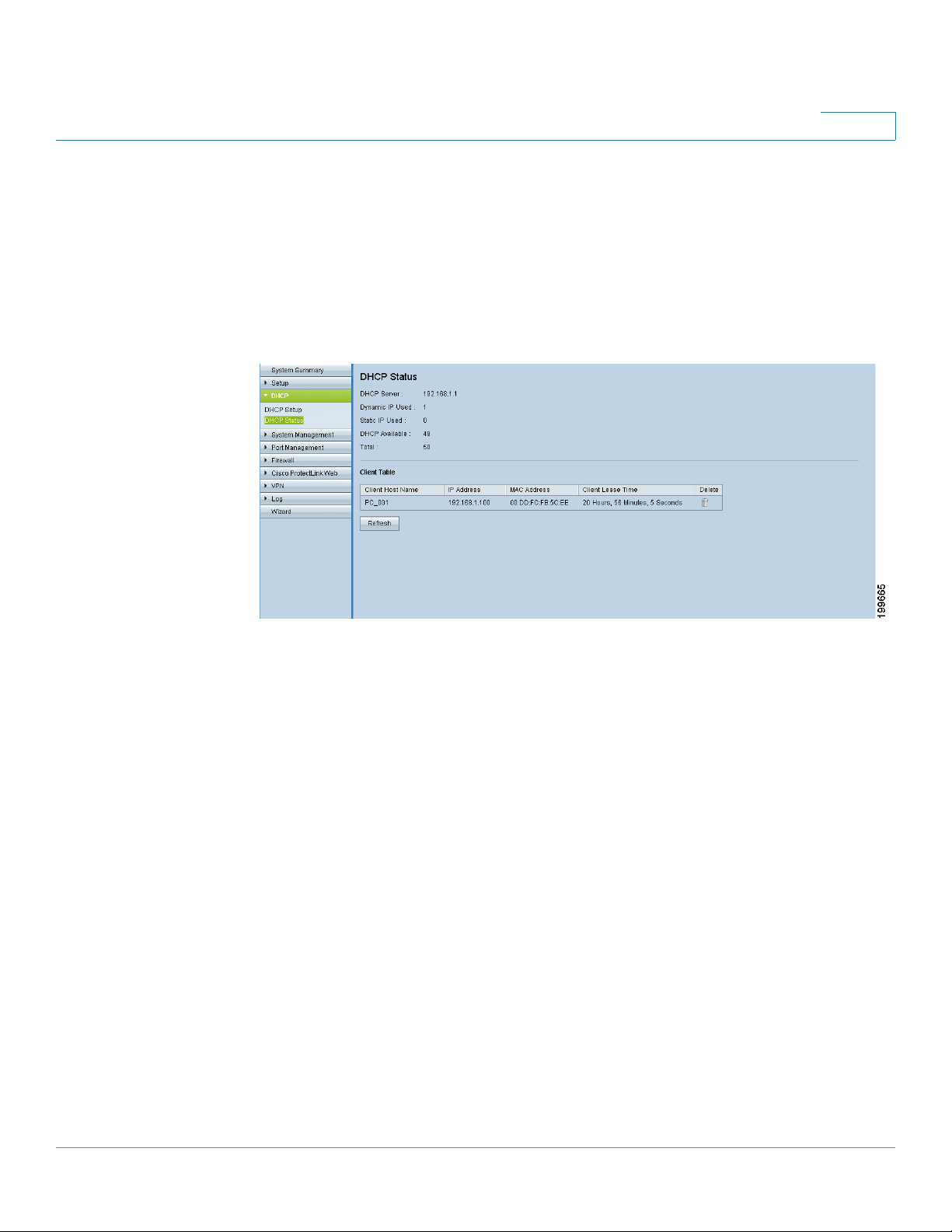
DHCP
Viewing the DHCP Status Information
Viewing the DHCP Status Information
4
Use the DHCP >
You can click Refresh to refresh the data. To release a client’s IP address, you can
click the Delete icon.
To open this page: Click DHCP > DHCP Status in the navigation tree.
DHCP Server
Status
page to view the status of the DHCP server and its clients.
For the DHCP server, the following information is shown:
• DHCP Server: The IP address of the DHCP server
• Dynamic IP Used: The number of dynamic IP addresses used.
• Static IP Used (IPv4 only): The number of static IP addresses used.
• DHCP Available: The number of dynamic IP addresses available
• To ta l : The total number of dynamic IP addresses that can be assigned by
the DHCP server.
Client Table
For all network clients using the DHCP server, the Client Table shows the current
DHCP client information. Click the IPv4 tab or the IPv6 tab to view the clients.
Note: The IPv6 tab is available only if you enabled Dual-Stack IP on the Network >
Setup page.
• Client Host Name: The name assigned to a client host.
• IP Address: The dynamic IP address assigned to a client.
Cisco Small Business RV0xx Series Routers Administration Guide 70
Page 71

DHCP
Router Advertisement (IPv6)
• MAC Address (IPv4 only): The MAC address of a client.
• Client Lease Time: The amount of time that a network user can remain
connected to the router with a dynamic IP address.
• Delete (IPv4 only): Click the icon to delete the lease and disconnect the
client.
Router Advertisement (IPv6)
Use the DHCP > Router Advertisement page to enable the RADVD (Router
Advertisement Daemon) for IPv6 auto-configuration and routing. When this
feature is enabled, messages are sent by the router periodically and in response
to solicitations. A host uses the information to learn the prefixes and parameters
for the local network. Disabling this feature effectively disables auto-configuration,
requiring manual configuration of the IPv6 address, subnet prefix, and default
gateway on each device.
4
This page is available if you enabled Dual-Stack IP on the Setup > Network page.
If you did not do so, a message appears when you try to open this page. After
reading the message, you can click OK to configure the network settings, or click
Cancel simply to close the message.
To open this page: Click DHCP > Router Advertisement in the navigation tree.
NOTE Before navigating away from this page, click Save to save your settings, or click
Cancel to undo them. Any unsaved changes are abandoned.
• Enable Router Advertisement: To enable this feature, check the box, and
then complete the other fields on the page. To disable this feature, uncheck
the box.
• Advertise Mode: Choose one of the following options:
- Unsolicited Multicast: Select this option to send Router Advertisement
messages to all interfaces in the multicast group. This option is the
default setting. If you choose this option, also enter the Advertisement
Interval, which is the interval at which Router Advertisement messages
are sent. Enter any value between 10 and 1800 seconds. The default is
30 seconds.
- Unicast only: Select this option to send Router Advertisement
messages only to well-known IPv6 addresses.
Cisco Small Business RV0xx Series Routers Administration Guide 71
Page 72

DHCP
Router Advertisement (IPv6)
4
• RA Flags: Choose whether or not hosts can use DHCPv6 to obtain
addresses and other information. The options are described below.
- Enabling the Managed flag only: Check the Managed box if you want
hosts to use an administered /stateful configuration protocol (DHCPv6)
to obtain stateful addresses and other information through DHCPv6.
- Enabling the Other flag only: Check the Other box if you want hosts to
use an administered/stateful configuration protocol (DHCPv6) to obtain
other, non-address information, such as DNS server addresses.
- Enabling both flags: Check both boxes if you want hosts to obtain
addresses and other information through DHCPv6.
- Disabling both flags: Uncheck both boxes if you want hosts to obtain
addresses and other information through router advertisements and not
DHCPv6.
• Router Preference: Choose High, Medium, or Low. This preference metric
is useful in a network topology in which multi-homed hosts have access to
multiple routers. This metric helps a host to choose an appropriate router. If
two routers are reachable, the one with the higher preference will be
chosen. These values are ignored by hosts that do not implement router
preference. The default setting is High.
• MTU: Enter the size of the largest packet that can be sent over the network.
The MTU (Maximum Transmission Unit) is used in Router Advertisement
messages to ensure that all nodes on the network use the same MTU value
when the LAN MTU is not well-known. The default setting is 1500 bytes,
which is the standard value for Ethernet networks. For PPPoE connections,
the standard is 1492 bytes. Unless your ISP requires a different setting, this
setting should not be changed.
• Router Lifetime: Enter the time in seconds that the Router Advertisement
messages will exist on the route. The default is 3600 seconds.
Cisco Small Business RV0xx Series Routers Administration Guide 72
Page 73

System Management
Use the System Management module to manage advanced settings, to configure
diagnostic tools, and to perform tasks such as firmware upgrades, backups, and
reboots. Refer to these topics:
• Setting Up Dual WAN and Multi-WAN Connections, page 73
• Managing the Bandwidth Settings, page 81
5
• Setting Up SNMP, page 84
• Enabling Device Discovery with Bonjour, page 85
• Using Built-In Diagnostic Tools, page 87
• Restoring the Factory Default Settings, page 89
• Upgrading the Firmware, page 90
• Restarting the Router, page 91
• Backing Up and Restoring the Settings, page 92
Setting Up Dual WAN and Multi-WAN Connections
Use the System Management > Dual WAN page (or Multi-WAN on RV016) to
configure the settings for your Internet connections, if you are using more than one
WAN inter face.
To open this page: Click System Management > Dual WAN (or Multi-WAN on
RV016) in the navigation tree.
NOTE Before navigating away from this page, click Save to save your settings, or click
Cancel to undo them. Any unsaved changes are abandoned.
Cisco Small Business RV0xx Series Routers Administration Guide 73
Page 74

System Management
Setting Up Dual WAN and Multi-WAN Connections
Mode - Cisco RV042, RV042G, and RV082
5
You can configure up to two Internet connections by using the Internet port and the
DMZ/Internet port. You can choose one of the following modes to manage your
WAN c on nect io ns:
• Smart Link Backup: Choose this mode to ensure continuous connectivity. If
the primary WAN connection is unavailable, the backup WAN connection is
used.
• Load Balance: Choose this mode to use both Internet connections
simultaneously to increase the available bandwidth. The router balances the
traffic between the two interfaces in a weighted round robin fashion.
NOTE: DNS queries are not subject to load balancing.
Cisco Small Business RV0xx Series Routers Administration Guide 74
Page 75

System Management
Setting Up Dual WAN and Multi-WAN Connections
Mode - Cisco RV016
5
You can configure up to seven Internet connections by using the two Internet ports
and the five dual-function ports. You can choose one of the following modes to
manage your WAN connections:
• Intelligent Balancer (Auto Mode): Select this option to balance traffic
between all interfaces to increase the available bandwidth. The router
balances the traffic between the interfaces in a weighted round robin
fashion.
• IP Group (By Users): Select this option to group traffic on each WAN
interface by priority levels or classes of service (CoS). With this feature, you
can ensure bandwidth and higher priority for the specified services and
users. All traffic that is not added to the IP Group uses Intelligent Balancer
mode. To specify the services and users, click the Edit icon for the WAN
interface and then add protocol binding entries for each service, IP address,
or range of IP addresses.
NOTE: The Router reserves at least one WAN port for non-IP Group users,
so WAN1 will always be set to Intelligent Balancer (Auto Mode). Protocol
binding is not available for WAN1.
Cisco Small Business RV0xx Series Routers Administration Guide 75
Page 76

System Management
Setting Up Dual WAN and Multi-WAN Connections
Interface Setting
Click the Edit icon for the interface that you want to set up. Then enter the settings
on the Edit Dual WAN settings page. For more information, see Editing the Dual
WAN and Multi-WAN Settings, page 77.
NOTE If there are unsaved changes on the Dual WAN page, a warning appears. You can
click OK to close the message. Then click Save to save your changes. After saving
your changes, click the Edit icon. Alternatively, when the warning appears, click
Cancel to continue to the edit page without saving the changes.
5
Cisco Small Business RV0xx Series Routers Administration Guide 76
Page 77

5
Editing the Dual WAN and Multi-WAN Settings
The Dual WAN Settings page (Multi-WAN Settings on RV016) appears after you
click the Edit icon for a WAN interface on the Dual WAN (or Multi-WAN) page. Enter
the interface settings, as needed.
NOTE Before navigating away from this page, click Save to save your settings, or click
Cancel to undo them. Any unsaved changes are abandoned.
Max Bandwidth Provided by ISP:
In this section, enter the maximum bandwidth settings as specified by your
Internet Service Provider. If the bandwidth exceeds the specified number, then the
router uses another WAN interface for the next connection.
• Upstream: Enter the maximum upstream bandwidth provided by your ISP.
The default is 512 kbit/sec.
• Downstream: Enter the maximum downstream bandwidth provided by
your ISP. The default is 512 kbit/sec.
Network Service Detection:
Optionally, check the box to allow the router to detect network connectivity by
pinging specified devices. Then enter the settings below. Uncheck the box to
disable this feature.
• Retry count: Enter the number of times to ping a device. The default is 5.
• Retry timeout: Enter the number of seconds to wait between pings. The
default is 30 seconds.
• When Fail: Choose the action that will be taken if a ping test fails. If you
choose Generate the Error Condition in the System Log, the router
Cisco Small Business RV0xx Series Routers Administration Guide 77
Page 78

5
records the failure in the System Log. There is no failover to the other
interface. If you choose Remove the Connection, failover occurs and the
backup interface is used. When the WAN port’s connectivity is restored, its
traffic is restored.
• Default Gateway, ISP Host, Remote Host, and DNS Lookup Host: Check
the box for each device that you want to ping to determine network
connectivity. For an ISP host or a remote host, enter the IP address. For a
DNS Lookup host, enter a host name or domain name. Uncheck a box if you
do not want to ping this device for network service detection.
Protocol Binding (for Cisco RV016 only, when Load Balancer is selected):
Use this feature to require this interface to be used for specified protocols and
specified source and destination addresses. If you enabled IP Group mode, this
feature is not available.
Add or update entries as needed. Remember that your entries are not saved until
you click the Save button.
• To add a new entry to the list: Enter the settings as described below, and
then click Add to list.
- Service: Choose a service (or All Traffic) to bind to this WAN interface. If
a service is not listed, you can click Service Management to add it. For
more information, see Adding a service, page 79.
- Source IP and Destination IP: Specify the internal sources and the
external destinations for the traffic that goes through this WAN port. For
a range of IP addresses, enter the first address in the first field and the
final address in the To field. For a single IP address, enter the same
address in both fields.
- Enable: Check the box to enable this rule, or uncheck the box to disable
it.
• To add another entry to the list: Enter the information, and then click Add
to list.
• To modify an entry in the list: Click the entry that you want to modify. The
information appears in the text fields. Make the changes, and then click
Update. If you do not need to make changes, you can click Add New to deselect the entry and clear the text fields.
Cisco Small Business RV0xx Series Routers Administration Guide 78
Page 79

5
• To delete an entry from the list: Click the entry that you want to delete, and
then click Delete. To select a block of entries, click the first entry, hold down
the Shift key, and then click the final entry in the block. To select individual
entries, press the Ctrl key while clicking each entry. To de-select an entry,
press the Ctrl key while clicking the entry.
Adding a service
To add a new entry to the Service list, or to change an entry that you created
previously, click Service Management. If the web browser displays a warning
about the pop-up window, allow the blocked content.
In the Service Management window, add or update entries as needed. Before
closing this window, click OK to save your settings, or click Cancel to undo them.
Any unsaved changes are abandoned.
• To add a service to the list: Enter the following information, and then click
Add to List. You can have up to 30 services in the list.
- Service Name: Enter a short description.
- Protocol: Choose the required protocol. Refer to the documentation for
the service that you are hosting.
- Port Range: Enter the required port range.
Cisco Small Business RV0xx Series Routers Administration Guide 79
Page 80

5
- To add another new service: Enter the information, and then click Add
to list.
- To modify a service you created: Click the service in the list. The
information appears in the text fields. Make the changes, and then click
Update. If you do not need to make changes, you can click Add New to
de-select the service and clear the text fields.
- To delete a service from the list: Click the entry that you want to delete.
To select a block of entries, click the first entry, hold down the Shift key,
and click the final entry in the block. To select individual entries, hold
down the Ctrl key while clicking. Click Delete.
Cisco Small Business RV0xx Series Routers Administration Guide 80
Page 81
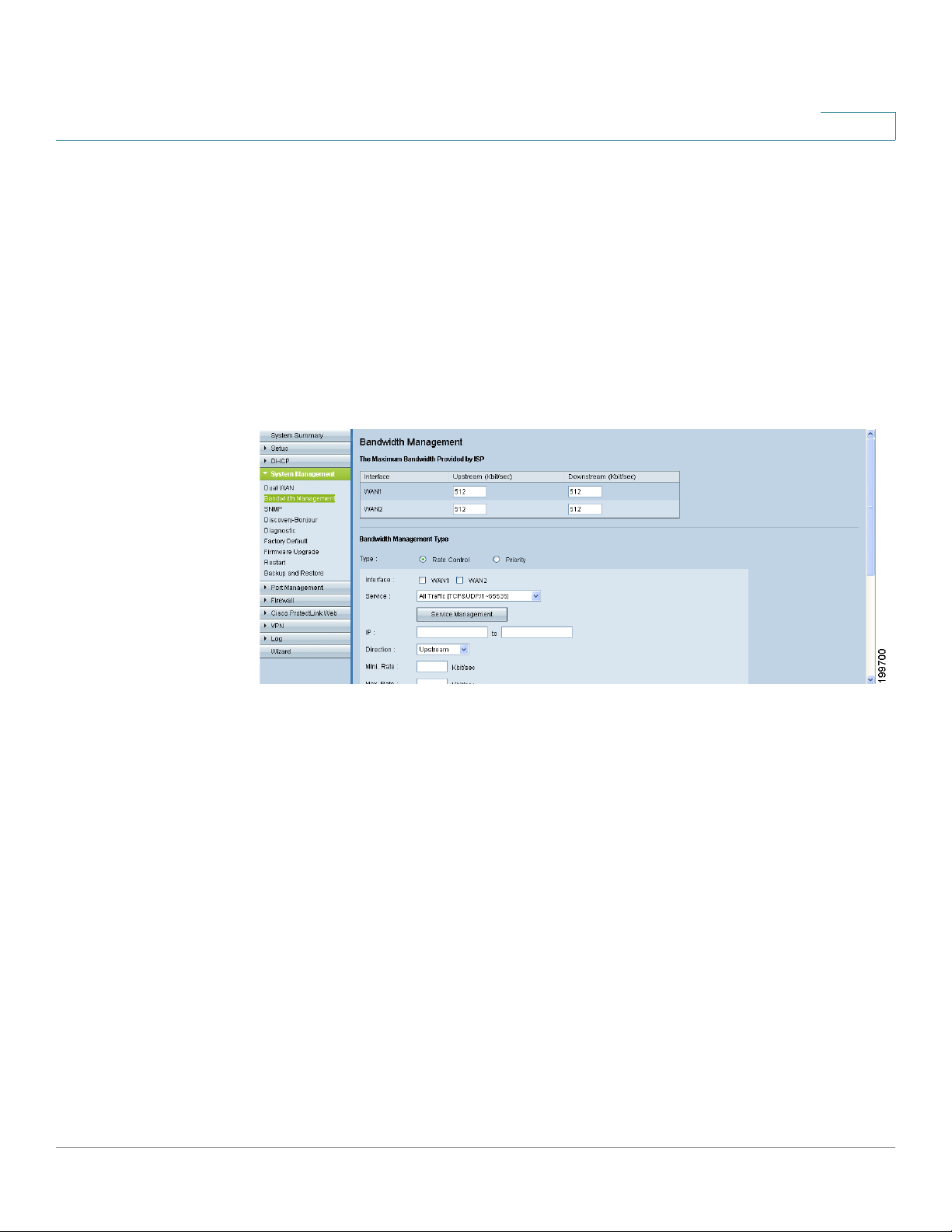
Managing the Bandwidth Settings
Managing the Bandwidth Settings
Use the System Management > Bandwidth Management page to adjust the
bandwidth settings for upstream and downstream traffic and to configure Quality
of Service (QoS) settings for various types of traffic. For example, you can enter
bandwidth rules to ensure quality for voice services. For a detailed example, see
Appendix F, “Bandwidth Management.”
To open this page: Click System Management > Bandwidth Management in the
navigation tree.
5
NOTE Before navigating away from this page, click Save to save your settings, or click
Cancel to undo them. Any unsaved changes are abandoned.
Max Bandwidth Provided by ISP
Enter the maximum bandwidth settings as specified by your Internet Service
Provider.
• Upstream: Enter the maximum upstream bandwidth provided by your ISP.
The default is 512 kbit/sec.
• Downstream: Enter the maximum downstream bandwidth provided by
your ISP. The default is 12 kbit/sec.
Bandwidth Management Type
Choose one of the following management options:
• Rate Control: Choose this option to specify minimum (guaranteed)
bandwidth and maximum (limited) bandwidth for each service or IP
address.
Cisco Small Business RV0xx Series Routers Administration Guide 81
Page 82

Managing the Bandwidth Settings
Select an Interface. Add the services that are subject to bandwidth management.
5
• Priority: Choose this option to manage the bandwidth by identifying high-
priority and low-priority services.
• To add a new service to the list: Enter the settings as described below,
and then click Add to List. You can add up to 100 services.
- Service: Select a service to manage. If a service is not listed, you can
click Service Management to add a service. For more information, see
Adding a service, page 83.
- IP (for Rate Control only): Enter the IP address or range you need to
control. To include all internal IP addresses, keep the default setting.
- Direction: Select Upstream for outbound traffic, or select Downstream
for inbound traffic.
- Min. Rate (for Rate Control only): Enter the minimum rate (Kbit/sec) for
the guaranteed bandwidth.
- Max. Rate (for Rate Control only): Enter the maximum rate (Kbit/sec) for
the guaranteed bandwidth.
- Priority (for Priority management only): Choose the priority for this
service: High or Low.
- Enable: Check the box to enable this feature, or uncheck the box to
disable this feature.
• To add another service to the list: Enter the information, and then click Add
to list.
• To modify a service in the list: Click the entry that you want to modify. The
information appears in the text fields. Make the changes, and then click
Update. If you do not need to make changes, you can click Add New to deselect the entry and clear the text fields.
• To delete an entry from the list: Click the entry that you want to delete, and
then click Delete. To select a block of entries, click the first entry, hold down
the Shift key, and then click the final entry in the block. To select individual
entries, press the Ctrl key while clicking each entry. To de-select an entry,
press the Ctrl key while clicking the entry.
Cisco Small Business RV0xx Series Routers Administration Guide 82
Page 83
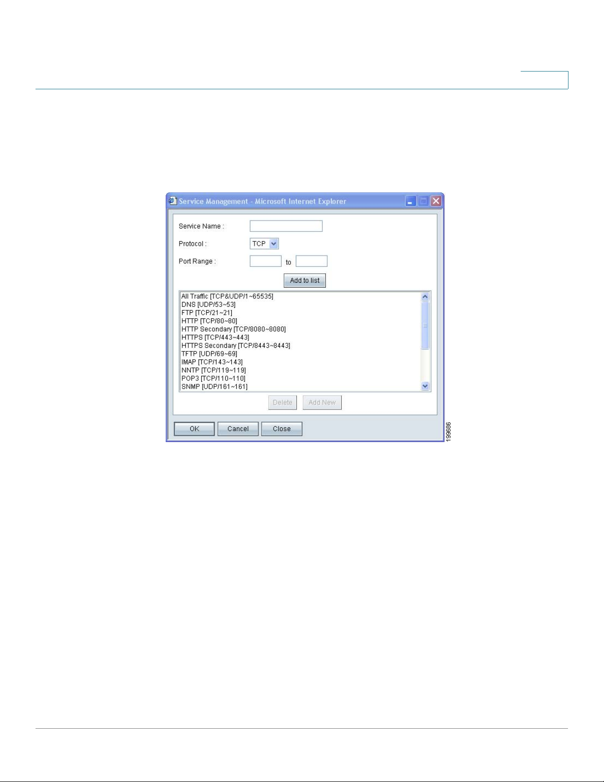
Managing the Bandwidth Settings
Adding a service
To add a new entry to the Service list, or to change an entry that you created
previously, click Service Management. If the web browser displays a warning
about the pop-up window, allow the blocked content.
5
In the Service Management window, add or update entries as needed. Before
closing this window, click OK to save your settings, or click Cancel to undo them.
Any unsaved changes are abandoned.
• To add a service to the list: Enter the following information, and then click
Add to List. You can have up to 30 services in the list.
- Service Name: Enter a short description.
- Protocol: Choose the required protocol. Refer to the documentation for
the service that you are hosting.
- Port Range: Enter the required port range.
• To add another new service: Enter the information, and then click Add to
list.
Cisco Small Business RV0xx Series Routers Administration Guide 83
Page 84
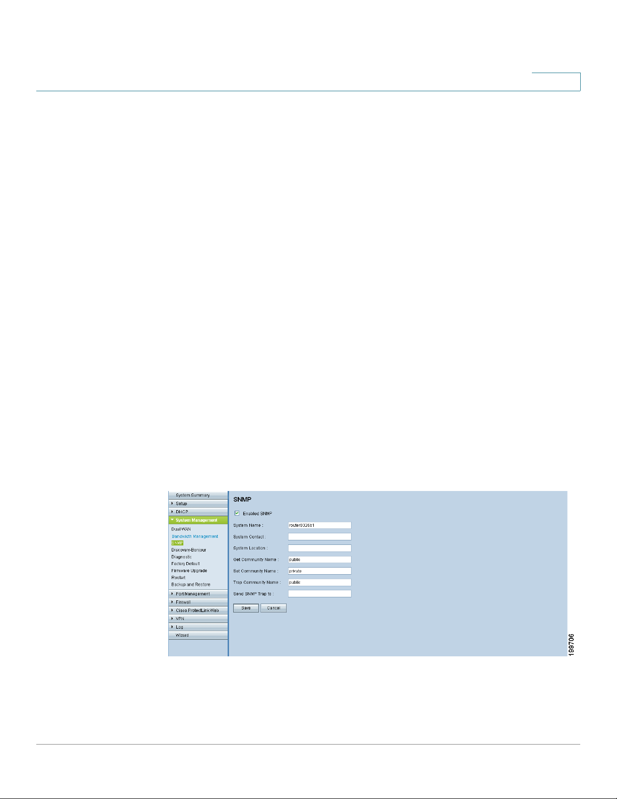
Setting Up SNMP
• To modify a service you created: Click the service in the list. The
• To delete a service from the list: Click the entry that you want to delete. To
Setting Up SNMP
Use the System Management > SNMP page to set up SNMP for this router. SNMP,
or Simple Network Management Protocol, is a network protocol that allows
network administrators to manage, monitor, and receive notifications of critical
events as they occur on the network. The router supports SNMP v1/v2c. The
router supports standard MIBs (Management Information Bases) such as MIBII, as
well as private MIBs. The router acts as an SNMP agent that replies to SNMP
commands from SNMP Network Management Systems. The commands it
supports are the standard SNMP commands get/next/set. It also generates trap
messages to notify the SNMP manager when alarm conditions occur. Examples
include reboots, power cycles, and WAN link events.
5
information appears in the text fields. Make the changes, and then click
Update. If you do not need to make changes, you can click Add New to deselect the service and clear the text fields.
select a block of entries, click the first entry, hold down the Shift key, and
click the final entry in the block. To select individual entries, hold down the
Ctrl key while clicking. Click Delete.
To open this page: Click System Management > SNMP in the navigation tree.
NOTE Before navigating away from this page, click Save to save your settings, or click
Cancel to undo them. Any unsaved changes are abandoned.
Cisco Small Business RV0xx Series Routers Administration Guide 84
Page 85

Enabling Device Discovery with Bonjour
• Enabled SNMP: Check this box to enable SNMP. Uncheck the box to
disable the this feature. This feature is enabled by default.
• System Name: Set the hostname for the router.
• System Contact: Enter the name of the network administrator who can be
contacted with updates about the router.
• System Location: Enter the network administrator’s contact information: an
e-mail address, telephone number, or pager number.
• Get Community Name: Enter a community string for authentication for
SNMP GET commands. You can enter a name including up to 64
alphanumeric characters. The default is public.
• Set Community Name: Enter a community string for authentication for
SNMP SET commands. You can enter a name including up to 64
alphanumeric characters. The default is private.
5
• Trap Community Name: Create the password that will be sent with each
trap to the SNMP manager. You can enter a name including up to 64
alphanumeric characters. The default is public.
• Send SNMP Trap to (For IPv4): Enter the IP address or domain name for
the server where you are running your SNMP management software.
• Send SNMP Trap to (For IPv6): When Dual-Stack IP is enabled on the
Network > Setup page, this field is available. Enter an IPv6 address or
domain name for the server where you are running your SNMP
management software.
Enabling Device Discovery with Bonjour
Use the System Management > Discovery-Bonjour page to enable or disable
Bonjour, a service discovery protocol. Bonjour locates network devices such as
computers and servers on your LAN. It may be required by network management
systems that you use. When this feature is enabled, the router periodically
multicasts Bonjour service records to its entire local network to advertise its
existence.
Cisco Small Business RV0xx Series Routers Administration Guide 85
Page 86
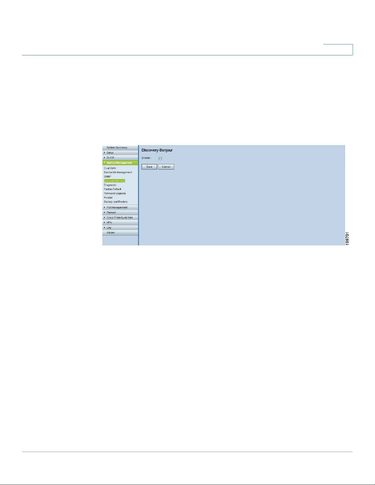
Enabling Device Discovery with Bonjour
NOTE For discovery of Cisco Small Business products, Cisco provides a utility that works
through a simple toolbar on the web browser. This utility discovers Cisco devices
in the network and display basic information, such as serial numbers and IP
addresses, to aid in the configuration and deployment. For more information and to
download the utility, please visit www.cisco.com/go/findit.
To open this page: Click System Management > Discovery-Bonjour in the
navigation tree.
5
Check the Enable box to enable Bonjour. Uncheck the box to disable this feature. It
is enabled by default.
Cisco Small Business RV0xx Series Routers Administration Guide 86
Page 87
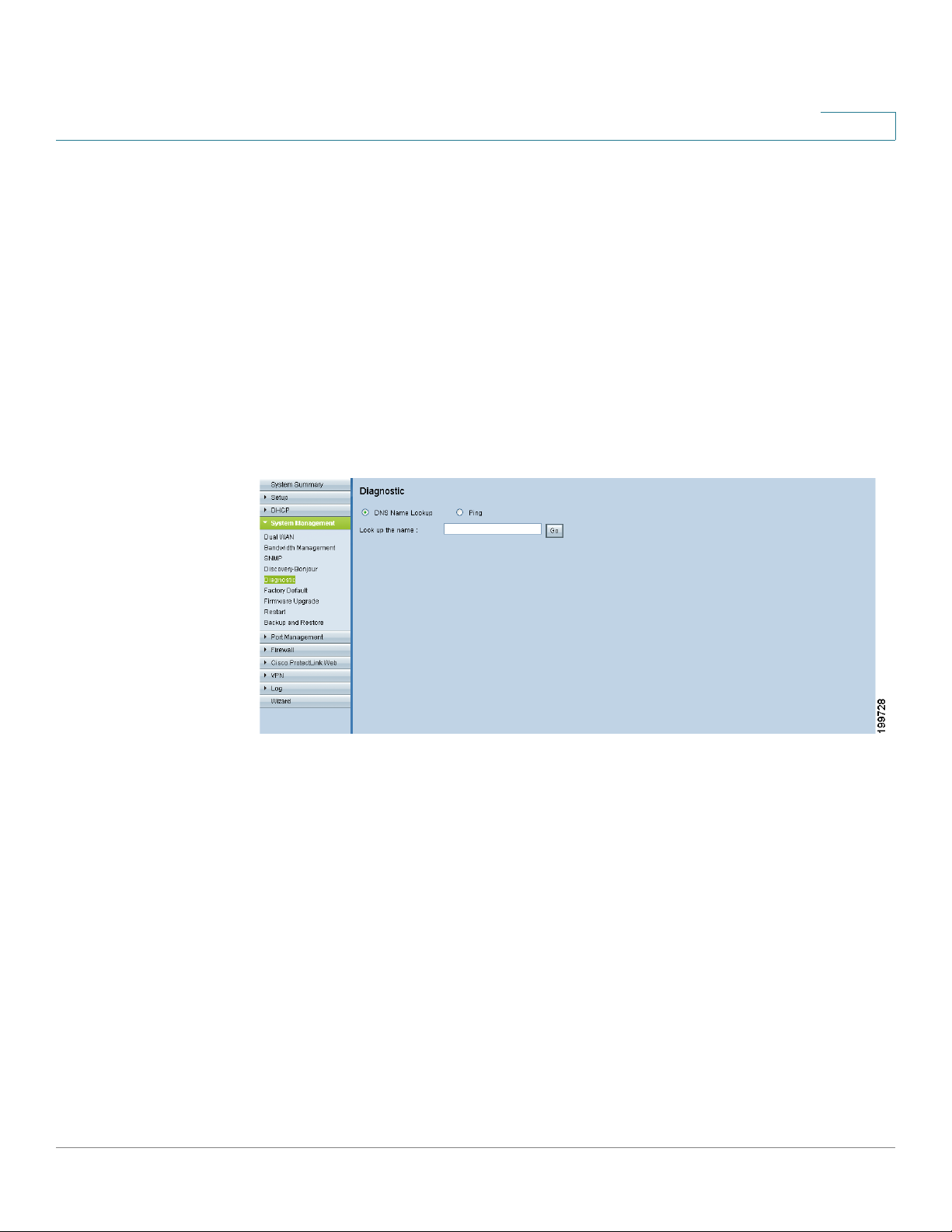
Using Built-In Diagnostic Tools
Using Built-In Diagnostic Tools
Use the System Management > Diagnostic page to access two built-in tools, DNS
Name Lookup and Ping. If you suspect a problem with connectivity, you can use
these tools to investigate.
To open this page: Click System Management > Diagnostic.
Choose DNS Name Lookup if you know a DNS name and want to learn the IP
address. Choose Ping to test the connectivity to a particular IP address on the
Internet.
DNS Name Lookup
5
Choose this option to test connectivity to the DNS server that you specified on the
Setup > Network page, or to look up an IP address that you want to use in the Ping
test.
In the Look up the name field, enter a host name, such as www.cisco.com. Do not
include a prefix such as http://. Then click Go. If the test is successful, the IP
address of the host appears.
NOTE This tool requires that the router can connect to a valid DNS server, based on the
WAN interface settings (
Cisco Small Business RV0xx Series Routers Administration Guide 87
Setup > Network
page).
Page 88
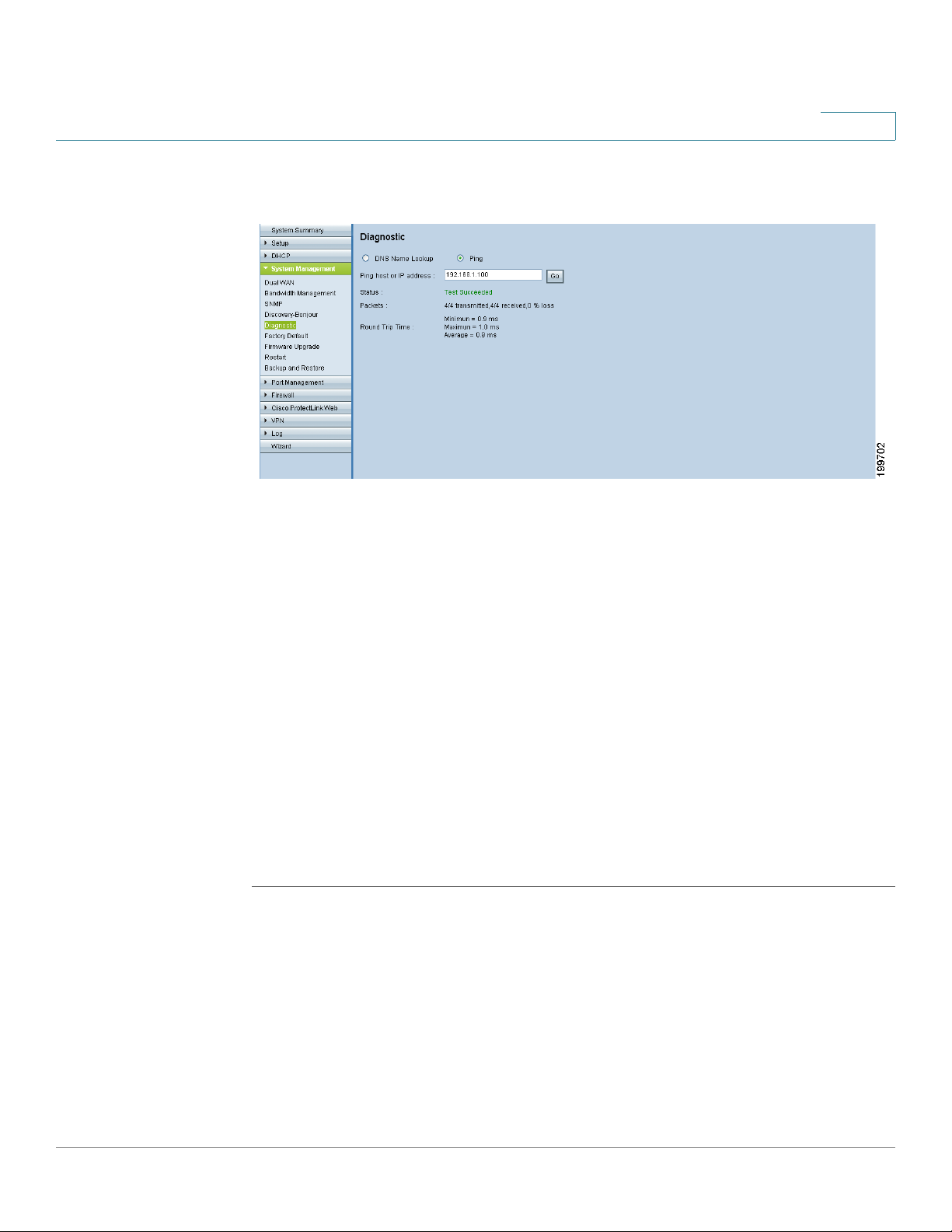
Using Built-In Diagnostic Tools
5
Ping
Choose this option to test connectivity to a specified host by entering the IP
address. If you do not know the IP address, use the DNS Lookup tool to learn it.
The ping test shows if the router is able to send a packet to a remote host and
receive a response. If users on the LAN are having problems accessing services
on the Internet, first try pinging your DNS server or other server at your ISP. If this
test is successful, try pinging devices outside the ISP. This will show if the problem
lies with the ISP’s connection.
Enter the IP Address, and then click Go. If the test is successful, the following
information appears:
• Status: The status of the ping test: Te st in g, Te st S uc ce e de d , or Tes t Fa i le d
• Packets: The number of packets transmitted, number of packets received,
and percentage of packets lost in the ping test
• Round Trip Time: The minimum, maximum, and average round trip times for
the ping test
Cisco Small Business RV0xx Series Routers Administration Guide 88
Page 89
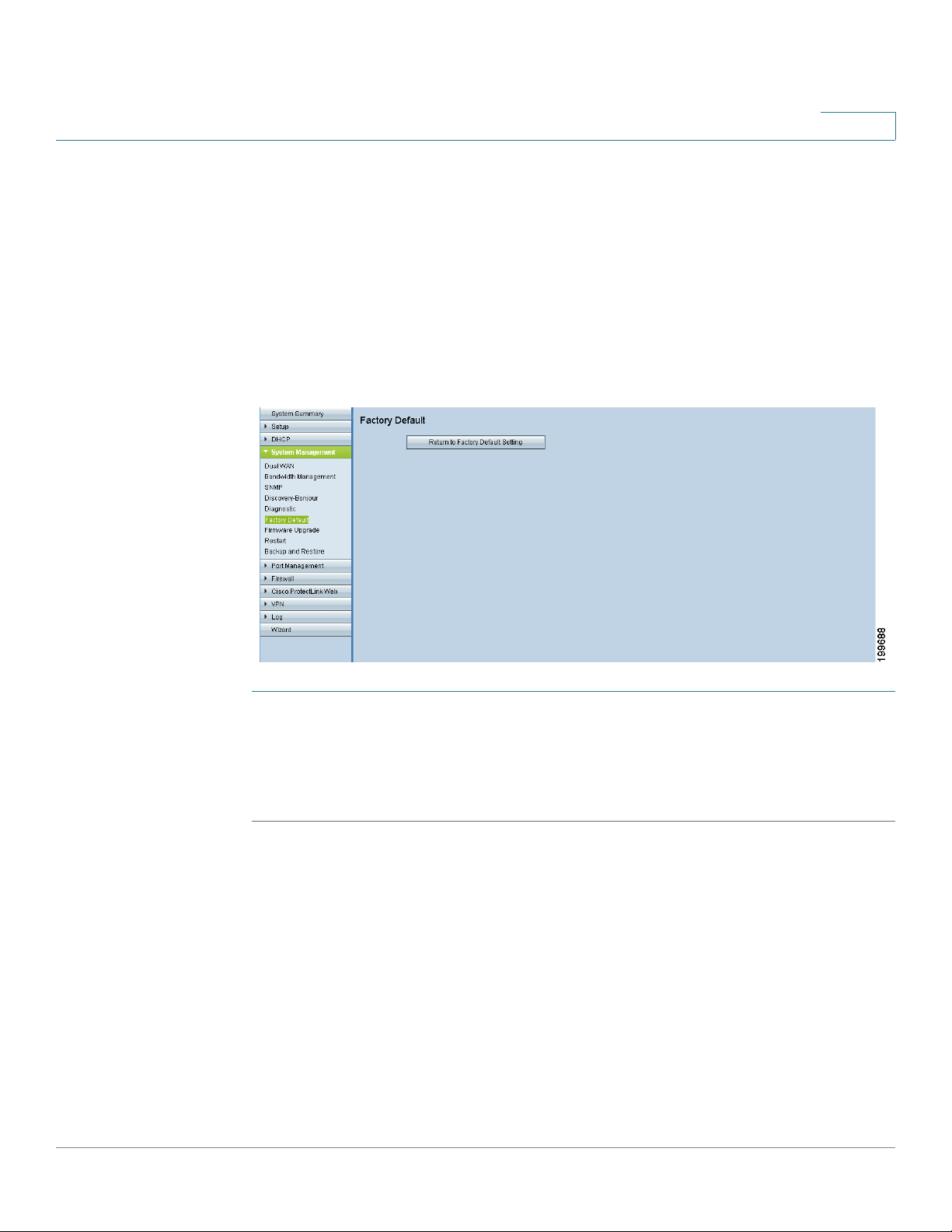
Restoring the Factory Default Settings
Restoring the Factory Default Settings
Use the System Management > Factory Default page to clear all of your
configuration information and restore the router to its factory default settings. Only
use this feature if you want to discard all the settings and preferences that you
have configured.
To open this page: Click System Management > Factory Default in the
navigation tree.
5
STEP 1 Click Return to Factory Default Setting if you want to restore the router to its
factory default settings.
STEP 2 When the confirmation message appears, click OK to continue. If you do not want
to restore the factory default settings, click Cancel.
Cisco Small Business RV0xx Series Routers Administration Guide 89
Page 90

Upgrading the Firmware
Upgrading the Firmware
Use the System Management > Firmware Upgrade page to download the latest
firmware for your router and to install it.
WARNING If you choose an earlier firmware version, the factory default settings will be used.
All custom settings.
WARNING Upgrading firmware may take several minutes. Do not turn off the power, press the
reset button, close the browser, or disconnect the link during this process.
5
To open this page: Click System Management > Firmware Upgrade in the
navigation tree.
Proceed as needed:
• To upgrade from a firmware file on your computer: Click the Browse
button, and select the extracted file. Click Firmware Upgrade Right Now.
After several minutes, the Rebooting message appears. Wait about a
minute for the browser to refresh. If the browser does not automatically
display the login page, you may need to re-enter the IP address in the
browser address bar. If your PC cannot reconnect to the configuration utility,
you may need to release and restore your IP address.
Cisco Small Business RV0xx Series Routers Administration Guide 90
Page 91
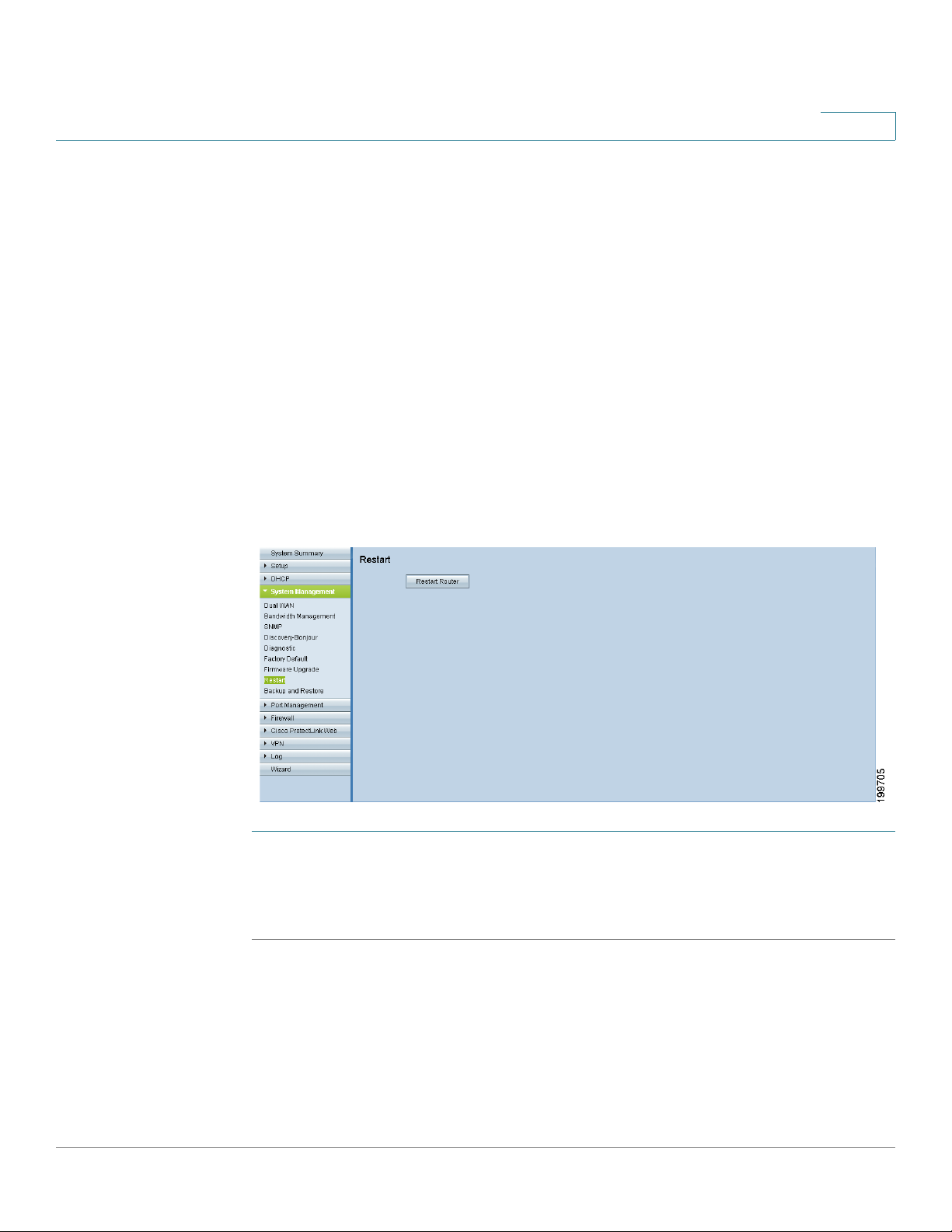
Restarting the Router
• To download the latest firmware from Cisco: Click Firmware Download
from Web Site.Your web browser opens the router information page on
Cisco.com. Click the Download Firmware button. Continue through the
screens to select the latest router firmware and to download the file. Extract
the file on your computer. Then perform the firmware upgrade as described
above.
Restarting the Router
If you need to restart the router, Cisco recommends that you use the Restart tool
on this page. When you restart from the System Management >
router will send out your log file (if logging is enabled) before it is reset.
To open this page: Click System Management > Restart in the navigation tree.
5
Restart
page, the
STEP 1 Click Restart Router to restart the router.
STEP 2 When the confirmation message appears, click OK to continue. If you do not want
to restart the router, click Cancel.
Cisco Small Business RV0xx Series Routers Administration Guide 91
Page 92

Backing Up and Restoring the Settings
Backing Up and Restoring the Settings
Use the System Management > Backup and Restore page to import, export, and
copy your configuration files. The router has two configuration files: the startup
and the mirror. The Startup file is the configuration file that the router loads when it
boots up. The router automatically copies the startup file to the mirror. Thus, the
Mirror file contains the last known valid configuration. In the future, if the Startup
configuration file fails for any reason, then the Mirror configuration file is used.
NOTE The router automatically copies the startup configuration to the mirror configuration
after 24 hours of running in stable condition (no reboot and no configuration
changes within a 24-hour period).
To open this page: Click System Management > Backup and Restore in the
navigation tree.
5
You can perform the following tasks:
• Restoring the Settings from a Configuration File, page 92
• Backing Up Configuration Files and Mirror Files, page 93
• Copying a Startup File or Mirror File, page 93
Restoring the Settings from a Configuration File
If you want to revert to previously saved settings, you can import a configuration
file.
Cisco Small Business RV0xx Series Routers Administration Guide 92
Page 93

Backing Up and Restoring the Settings
STEP 1 In the Restore Startup Configuration File section, click Browse.
STEP 2 Select a configuration file (.config).
STEP 3 Click Restore. This process may take up to a minute.
STEP 4 Click System Management > Restart in the navigation tree.
STEP 5 When the confirmation message appears, click OK. If you do not want to restart
the router, click Cancel. The imported settings are not applied until you restart the
router.
NOTE: Alternatively, you can use the Restart button. Press the Restart button for
one second and then release it to restart the router.
Backing Up Configuration Files and Mirror Files
You can save your startup and mirror configuration files to your computer. If
needed, you can use these files to restore the settings.
5
STEP 1 Click Backup Startup Configuration or Backup Mirror Configuration.
STEP 2 When the File Download window appears, click Save, and then choose a file
location. Optionally, you can enter a descriptive filename. Then click Save.
TIP: The default filenames are Startup.config and Mirror.config. It may be helpful
to enter a filename that includes the current date and time, for easier identification
if you need to import a file later.
STEP 3 Close the Download Complete window.
Copying a Startup File or Mirror File
If needed, you can manually copy your startup configuration file to your mirror
configuration file or you can copy your mirror to your startup.
TIP You can use this process to back up a known configuration before you make
changes. Copy the startup file to the mirror before making your changes. If you are
dissatisfied with your changes, copy the mirror to the startup to restore the
settings.
NOTE
• The startup configuration file is automatically copied to the mirror
configuration file every 24 hours.
Cisco Small Business RV0xx Series Routers Administration Guide 93
Page 94

Backing Up and Restoring the Settings
• If a setting is changed, the time counter resets, and the next automatic copy
will occur 24 hours later.
• If the mirror config file is still in its factory default state, copying the mirror to
the startup immediately resets the router to the factory default settings.
To copy a file, click the button:
• Copy Startup to Mirror: Click this button to replace the mirror file with the
startup file. The copy operation is performed immediately, with no option to
cancel. When the operation is finished, the browser page refreshes.
• Copy Mirror to Startup: Click this button to replace the startup file with the
mirror file. The copy operation is performed immediately, with no option to
cancel. After a short time, the router restarts. If your PC is unable to
immediately reload the login page, re-enter the IP address for the
configuration utility in the Address bar. Then log in.
5
Cisco Small Business RV0xx Series Routers Administration Guide 94
Page 95

Port Management
Use the Port Management module to configure port settings and view the port
status.
• Configuring the Port Settings, page 95
• Viewing the Status Information for a Port, page 97
6
Configuring the Port Settings
The default port settings should be sufficient for most small businesses, but you
can use the Port Management > Port Setup page to customize these settings if
needed. You can disable a port or customize its priority, speed, duplex mode, and
auto-negotiation settings. You also can enable port-based VLANs to control traffic
between devices on your network.
To open this page: Click Port Management > Port Setup in the navigation tree.
NOTE Before navigating away from this page, click Save to save your settings, or click
Cancel to undo them. Any unsaved changes are abandoned.
Cisco Small Business RV0xx Series Routers Administration Guide 95
Page 96

Port Management
Configuring the Port Settings
6
For Cisco RV016 only, choose the number of WAN ports from the drop-down list,
or keep the default number, 2. If you change the number, save your settings. (You
can also change the number of WAN ports by using the
The following read-only information is displayed for each port:
• Port ID: The port number or name, as it is labeled on the device
• Interface: The interface type: LAN, WAN, or DMZ
Enter the following settings, as needed:
• Disable: Check this box to disable a port. By default, all ports are enabled.
• Priority (for LAN ports only): Use this setting to ensure Quality of Service
by prioritizing the traffic for devices on particular ports. For example, you
might assign High priority to a port that is used for gaming or
videoconferencing. For each port, select the appropriate priority level, High
or Normal. The default setting is Normal.
Setup > Network
page.)
• Speed: If you want to adjust this setting, first uncheck the Enable box in the
Auto Neg column to disable auto-negotiation. Then select the port speed:
10M or 100M.
• Duplex: If you want to set the duplex mode, first uncheck the Enable box in
the Auto Neg column to disable auto-negotiation. Select the duplex mode,
Half or Full.
• Auto Neg.: Check the Enable box to allow the router to auto-negotiate
connection speeds and duplex mode. This feature is enabled by default.
• VLAN (for LAN ports only): All LAN ports are on VLAN 1 by default. To place
a port on a separate VLAN, choose a VLAN from the drop-down list.
The number of available VLANs equals the number of LAN ports: 4 on Cisco
RV042 and RV042G, 8 on Cisco RV082, and up to 13 on Cisco RV016
(depending on the usage of the dual-function ports). For example, on Port 4,
you may have an Ethernet switch that provides Internet connectivity to
guest users in a conference room. To prevent your guests from accessing
the file servers and printers on your LAN, you could put Port 4 on VLAN 2
and leave the other ports on VLAN 1. There is no communication between
devices on separate VLANs.
Cisco Small Business RV0xx Series Routers Administration Guide 96
Page 97
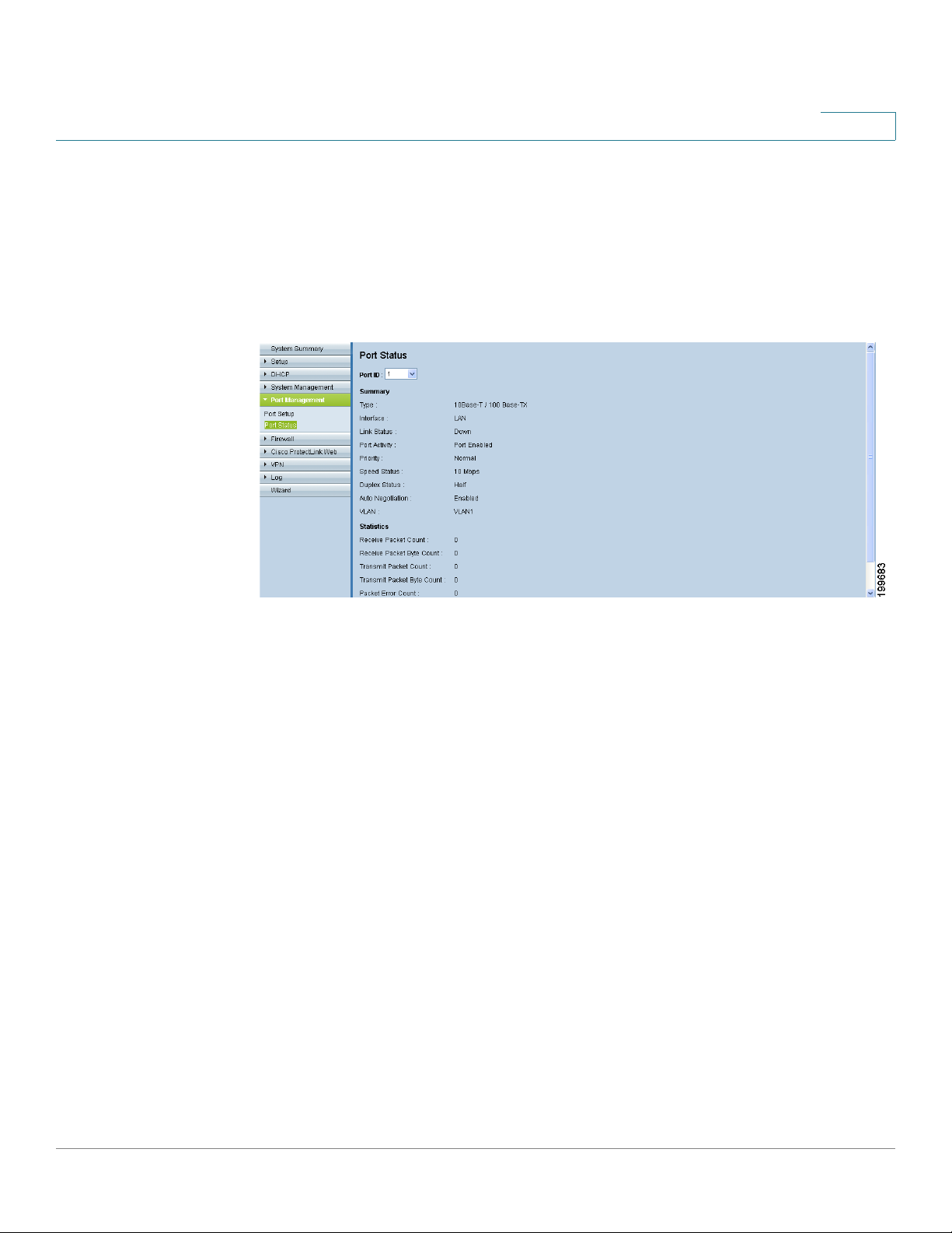
Port Management
Viewing the Status Information for a Port
Viewing the Status Information for a Port
Use the Port Management > Port Status page to view information and statistics
for a selected port.
To open this page: Click Port Management > Port Status in the navigation tree.
6
From the Port ID list, choose a port. You can click Refresh to update the data.
Summary
For the selected port, the Summary table displays the following:
• Type: The port type
• Interface: The interface type, LAN or WAN,
• Link Status: The status of the connection
• Port Activity: The status of the port
• Speed Status: The speed of the port, 10 Mbps or 100 Mbps
• Duplex Status: The duplex mode: Half or Full.
• Auto negotiation: The status of the feature
• VLAN: The VLAN of the port
Cisco Small Business RV0xx Series Routers Administration Guide 97
Page 98

Port Management
Viewing the Status Information for a Port
Statistics
For the selected port, the Statistics table displays the following:
• Port Receive Packet Count: The number of packets received
• Port Receive Packet Byte Count: The number of packet bytes received
• Port Transmit Packet Count: The number of packets transmitted
• Port Transmit Packet Byte Count: The number of packet bytes
transmitted
• Port Packet Error Count: The number of packet errors
6
Cisco Small Business RV0xx Series Routers Administration Guide 98
Page 99
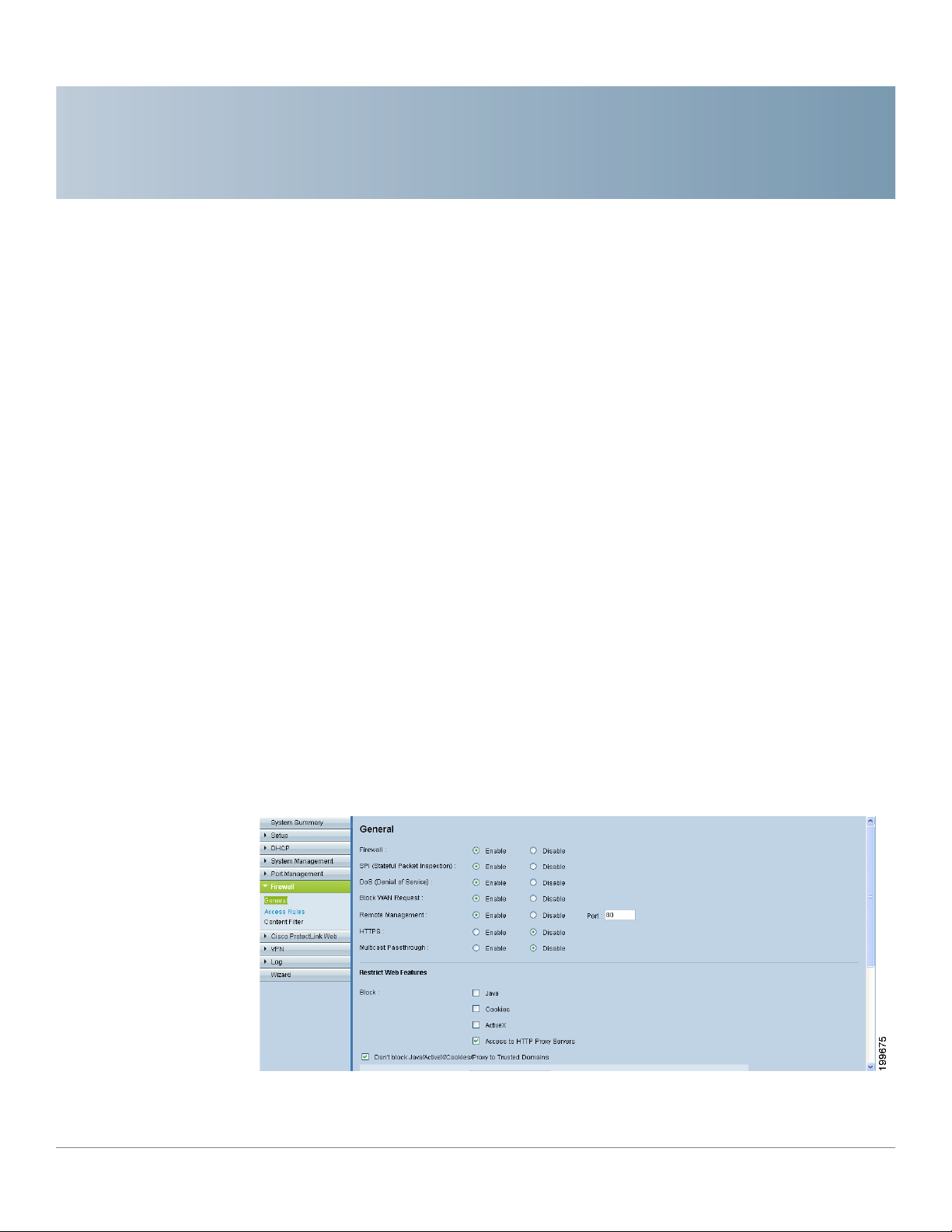
Firewall
7
Use the Firewall module to configure the firewall features, create access rules, and
set content filters to control your users’ Internet activities. Refer to these topics:
• Configuring the General Firewall Settings, page 99
• Managing Access Rules, page 104
• Configuring Firewall Access Rules, page 103
• Using Content Filters to Control Internet Access, page 110
Configuring the General Firewall Settings
The default firewall settings should be sufficient for most small businesses.
However, you can use the Firewall > General page to disable the firewall or to
specify the types of attacks that you want to block. You also can restrict
potentially risky website features such as Java and cookies.
To open this page: Click Firewall > General in the navigation tree.
Cisco Small Business RV0xx Series Routers Administration Guide 99
Page 100

Firewall
Configuring the General Firewall Settings
NOTE
• If you want to disable the firewall (not recommended), you can do so only if
you have configured the administrator password. If you are still using the
default password, you must change it. For more information, see Changing
the Administrator Username and Password, page 40.
• Before navigating away from this page, click Save to save your settings, or
click Cancel to undo them. Any unsaved changes are abandoned.
Enable or disable the firewall and related features:
• Firewall: Choose to enable or disable the firewall. This feature is enabled
by default and is strongly recommended to protect your network. Enabling
or disabling the firewall also affects several related features, as described
below. Disabling the firewall also disables Access Rules and Content Filters.
If you choose Disable and you are still using the default administrator
password, a message appears. To protect your router from unauthorized
access, you must change the password before you can disable the firewall.
Click OK to continue to the Password page, or click Cancel to remain on the
current page. After you change your password, you can return to this page
to resume this procedure.
7
• SPI (Stateful Packet Inspection): When enabled, this feature allows the
router to review the information that passes through the firewall. It inspects
all packets based on the established connection, prior to passing the
packets for processing through a higher protocol layer. This feature can be
enabled only when the firewall is enabled.
• DoS (Denial of Service): When enabled, this feature protects internal
networks from Internet attacks, such as SYN Flooding, Smurf, LAND, Ping of
Death, IP Spoofing, and reassembly attacks. This feature can be enabled
only when the firewall is enabled.
• Block WAN Request: When enabled, this feature allows the router to drop
both unaccepted TCP requests and ICMP packets from the WAN side.
Hackers will not find the router by pinging the WAN IP address. This feature
can be enabled only when the firewall is enabled.
• Remote Management: When enabled, this feature allows you to connect to
the router’s web-based configuration utility through a WAN connection. This
feature is disabled by default. It can be enabled only when the firewall is
enabled. If you want to enable remote management, you should first
configure a strong administrator password on the
This precaution prevents an unauthorized user from accessing the router
with the default password. If you enable this feature, you can keep the
Setup > Password
page.
Cisco Small Business RV0xx Series Routers Administration Guide 100
 Loading...