

Page 1

Cisco RPS 675 Redundant Power System Hardware Installation Guide
February 2008
Americas Headquarters
Cisco Systems, Inc.
170 West Tasman Drive
San Jose, CA 95134-1706
USA
http://www.cisco.com
Tel: 408 526-4000
800 553-NETS (6387)
Fax: 408 527-0883
Text Part Number: 78-15201-04
Page 2

THE SPECIFICATIONS AND INFORMATION REGARDING THE PRODUCTS IN THIS MANUAL ARE SUBJECT TO CHANGE WITHOUT
NOTICE. ALL STATEMENTS, INFORMATION, AND RECOMMENDATIONS IN THIS MANUAL ARE BELIEVED TO BE ACCURATE BUT
ARE PRESENTED WITHOUT WARRANTY OF ANY KIND, EXPRESS OR IMPLIED. USERS MUST TAKE FULL RESPONSIBILITY FOR
THEIR APPLICATION OF ANY PRODUCTS.
THE SOFTWARE LICENSE AND LIMITED WARRANTY FOR THE ACCOMPANYING PRODUCT ARE SET FORTH IN THE INFORMATION
PACKET THAT SHIPPED WITH THE PRODUCT AND ARE INCORPORATED HEREIN BY THIS REFERENCE. IF YOU ARE UNABLE TO
LOCATE THE SOFTWARE LICENSE OR LIMITED WARRANTY, CONTACT YOUR CISCO REPRESENTATIVE FOR A COPY.
The following information is for FCC compliance of Class A devices: This equipment has been tested and found to comply with the limits for a Class
A digital device, pursuant to part 15 of the FCC rules. These limits are designed to provide reasonable protection against harmful interference when
the equipment is operated in a commercial environment. This equipment generates, uses, and can radiate radio-frequency energy and, if not installed
and used in accordance with the instruction manual, may cause harmful interference to radio communications. Operation of this equipment in a
residential area is likely to cause harmful interference, in which case users will be required to correct the interference at their own expense.
The following information is for FCC compliance of Class B devices: The equipment described in this manual generates and may radiate
radio-frequency energy. If it is not installed in accordance with Cisco’s installation instructions, it may cause interference with radio and television
reception. This equipment has been tested and found to comply with the limits for a Class B digital device in accordance with the specifications in
part 15 of the FCC rules. These specifications are designed to provide reasonable protection against such interference in a residential installation.
However, there is no guarantee that interference will not occur in a particular installation.
Modifying the equipment without Cisco’s written authorization may result in the equipment no longer complying with FCC requirements for Class
A or Class B digital devices. In that event, your right to use the equipment may be limited by FCC regulations, and you may be required to correct
any interference to radio or television communications at your own expense.
You can determine whether your equipment is causing interference by turning it off. If the interference stops, it was probably caused by the Cisco
equipment or one of its peripheral devices. If the equipment causes interference to radio or television reception, try to correct the interference by
using one or more of the following measures:
• Turn the television or radio antenna until the interference stops.
• Move the equipment to one side or the other of the television or radio.
• Move the equipment farther away from the television or radio.
• Plug the equipment into an outlet that is on a different circuit from the television or radio. (That is, make certain the equipment and the television
or radio are on circuits controlled by different circuit breakers or fuses.)
Modifications to this product not authorized by Cisco Systems, Inc. could void the FCC approval and negate your authority to operate the product.
The Cisco implementation of TCP header compression is an adaptation of a program developed by the University of California, Berkeley (UCB) as
part of UCB’s public domain version of the UNIX operating system. All rights reserved. Copyright © 1981, Regents of the University of California.
NOTWITHSTANDING ANY OTHER WARRANTY HEREIN, ALL DOCUMENT FILES AND SOFTWARE OF THESE SUPPLIERS ARE
PROVIDED “AS IS” WITH ALL FAULTS. CISCO AND THE ABOVE-NAMED SUPPLIERS DISCLAIM ALL WARRANTIES, EXPRESSED
OR
IMPLIED, INCLUDING, WITHOUT LIMITATION, THOSE OF MERCHANTABILITY, FITNESS FOR A PARTICULAR PURPOSE AND
NONINFRINGEMENT OR ARISING FROM A COURSE OF DEALING, USAGE, OR TRADE PRACTICE.
IN NO EVENT SHALL CISCO OR ITS SUPPLIERS BE LIABLE FOR ANY INDIRECT, SPECIAL, CONSEQUENTIAL, OR INCIDENTAL
DAMAGES, INCLUDING, WITHOUT LIMITATION, LOST PROFITS OR LOSS OR DAMAGE TO DATA ARISING OUT OF THE USE OR
INABILITY TO USE THIS MANUAL, EVEN IF CISCO OR ITS SUPPLIERS HAVE BEEN ADVISED OF THE POSSIBILITY OF SUCH
DAMAGES.
Any Internet Protocol (IP) addresses used in this document are not intended to be actual addresses. Any examples, command display output, and
figures included in the document are shown for illustrative purposes only. Any use of actual IP addresses in illustrative content is unintentional and
coincidental.
CCDE, CCVP, Cisco Eos, Cisco StadiumVision, the Cisco logo, DCE, and Welcome to the Human Network are trademarks; Changing the Way We
Work, Live, Play, and Learn is a service mark; and Access Registrar, Aironet, AsyncOS, Bringing the Meeting To You, Catalyst, CCDA, CCDP, CCIE,
CCIP, CCNA, CCNP, CCSP, Cisco, the Cisco
Cisco
Systems logo, Cisco Unity, Collaboration Without Limitation, Enterprise/Solver, EtherChannel, EtherFast, EtherSwitch, Event Center, Fast
Step, Follow Me Browsing, FormShare, GigaDrive, HomeLink, Internet Quotient, IOS, iPhone, IP/TV, iQ Expertise, the iQ logo, iQ Net Readiness
Scorecard, iQuick Study, IronPort, the IronPort
Certified Internetwork Expert logo, Cisco IOS, Cisco Press, Cisco Systems, Cisco Systems Capital, the
logo, LightStream, Linksys, MediaTone, MeetingPlace, MGX, Networkers, Networking Academy,
Page 3

Network Registrar, PCNow, PIX, PowerPanels, ProConnect, ScriptShare, SenderBase, SMARTnet, Spectrum Expert, StackWise, The Fastest Way to
Increase Your Internet Quotient, TransPath, WebEx, and the WebEx
United States and certain other countries.
All other trademarks mentioned in this document or Website are the property of their respective owners. The use of the word partner does not imply
a partnership relationship between Cisco and any other company. (0801R)
Any Internet Protocol (IP) addresses used in this document are not intended to be actual addresses. Any examples, command display output, and
figures included in the document are shown for illustrative purposes only. Any use of actual IP addresses in illustrative content is unintentional and
coincidental.
Cisco RPS 675 Redundant Power System Hardware Installation Guide
© 2003–2008 Cisco Systems, Inc. All rights reserved.
logo are registered trademarks of Cisco Systems, Inc. and/or its affiliates in the
Page 4

Page 5

CONTENTS
Cisco Limited Lifetime Hardware Warranty Terms ix
Preface xiii
Audience xiii
Purpose xiii
Organization xiv
Conventions xiv
Statement 1071—Warning Definition xv
Related Publications xxiii
Obtaining Documentation and Submitting a Service Request xxiv
CHAPTER
CHAPTER
78-15201-04
1 Product Overview 1-1
Features 1-2
Front-Panel Description 1-3
LEDs 1-3
Standby/Active Button 1-6
Rear-Panel Description 1-8
Deployment Strategies 1-9
2 Installation 2-1
Preparing for Installation 2-1
Warnings 2-2
Cisco RPS 675 Redundant Power System Hardware Installation Guide
v
Page 6

Contents
EMC Regulatory Statements 2-4
U.S.A. 2-4
Statement 257—Class A Notice for Taiwan and Other Traditional
Chinese Markets 2-4
Statement 191—VCCI Class A Warning for Japan 2-5
Statement 294—Class A Warning for Korea 2-5
Statement 256—Class A Warning for Hungary 2-6
Site Requirements 2-7
Verifying the Package Contents 2-7
Installing the Switch 2-8
Table or Shelf-Mounting 2-8
Rack-Mounting 2-9
Planning Your Rack-Mount Installation 2-9
Tools and Equipment Required 2-10
Attaching the Brackets to the RPS 2-10
Mounting the RPS in a Rack 2-14
CHAPTER
APPENDIX
APPENDIX
APPENDIX
vi
Connecting the RPS 675 2-14
3 Troubleshooting 3-1
A Technical Specifications A-1
B Connector and Cable Specifications B-1
C Translated Safety Warnings C-1
Statement 17B—Overtemperature Warning C-2
Statement 43—Jewelry Removal Warning C-5
Statement 48—Stacking the Chassis Warning C-7
Statement 100C—Attaching the Cisco RPS (model PWR675-AC-RPS-N1) C-9
Cisco RPS 675 Redundant Power System Hardware Installation Guide
78-15201-04
Page 7

I
NDEX
Contents
Statement 265—Redundant Power Supply Connection Warning C-10
Statement 1001—Work During Lightning Activity C-12
Statement 1004—Installation Instructions C-13
Statement 1006—Chassis Warning for Rack-Mounting and Servicing C-15
Statement 1017—Restricted Area C-25
Statement 1019—Main Disconnecting Device C-28
Statement 1024—Ground Conductor C-30
Statement 1030—Equipment Installation C-34
Statement 1040—Product Disposal C-36
Statement 1073—No User-Serviceable Parts C-38
Statement 1074—Comply with Local and National Electrical Codes C-41
78-15201-04
Cisco RPS 675 Redundant Power System Hardware Installation Guide
vii
Page 8

Contents
viii
Cisco RPS 675 Redundant Power System Hardware Installation Guide
78-15201-04
Page 9

Cisco Limited Lifetime Hardware Warranty Terms
There are special terms applicable to your hardware warranty and various services
that you can use during the warranty period. Your formal Warranty Statement,
including the warranties and license agreements applicable to Cisco software, is
available on Cisco.com. Follow these steps to access and download the Cisco
Information Packet and your warranty and license agreements from Cisco.com.
1. Launch your browser, and go to this URL:
http://www.cisco.com/univercd/cc/td/doc/es_inpck/cetrans.htm
78-15201-04
The Warranties and License Agreements page appears.
2. To read t he Cisco Information Packet, follow these steps:
a. Click the Information Packet Number field, and make sure that the part
number 78-5235-03C0 is highlighted.
b. Select the language in which you would like to read the document.
c. Click Go.
The Cisco Limited Warranty and Software License page from the
Information Packet appears.
d. Read the document online, or click the PDF icon to download and print
the document in Adobe Portable Document Format (PDF).
Cisco RPS 675 Redundant Power System Hardware Installation Guide
ix
Page 10

Cisco Limited Lifetime Hardware Warranty Terms
Note You must have Adobe Acrobat Reader to view and print PDF
files. You can download the reader from Adobe’s website:
http://www.adobe.com
3. To read translated and localized warranty information about your product,
follow these steps:
a. Enter this part number in the Warranty Document Number field:
78-6310-02C0
b. Select the language in which you would like to view the document.
c. Click Go.
The Cisco warranty page appears.
d. Read the document online, or click the PDF icon to download and print
the document in Adobe Portable Document Format (PDF).
You can also contact the Cisco service and support website for assistance:
http://www.cisco.com/public/Support_root.shtml.
Duration of Hardware Warranty
A Cisco product hardware warranty is supported for as long as the original end
user continues to own or use the product, provided that the fan and power supply
warranty is limited to five (5) years. In the event of a discontinuance of product
manufacture, the Cisco warranty support is limited to five (5) years from the
announcement of the discontinuance.
Replacement, Repair, or Refund Policy for Hardware
Cisco or its service center will use commercially reasonable efforts to ship a
replacement part within ten (10) working days after receipt of the Return
Materials Authorization (RMA) request. Actual delivery times can vary,
depending on the customer location.
Cisco reserves the right to refund the purchase price as its exclusive warranty
remedy.
To Receive a Return Materials Authorization (RMA) Number
Contact the company from whom you purchased the product. If you purchased the
product directly from Cisco, contact your Cisco Sales and Service Representative.
Cisco RPS 675 Redundant Power System Hardware Installation Guide
x
78-15201-04
Page 11
Cisco Limited Lifetime Hardware Warranty Terms
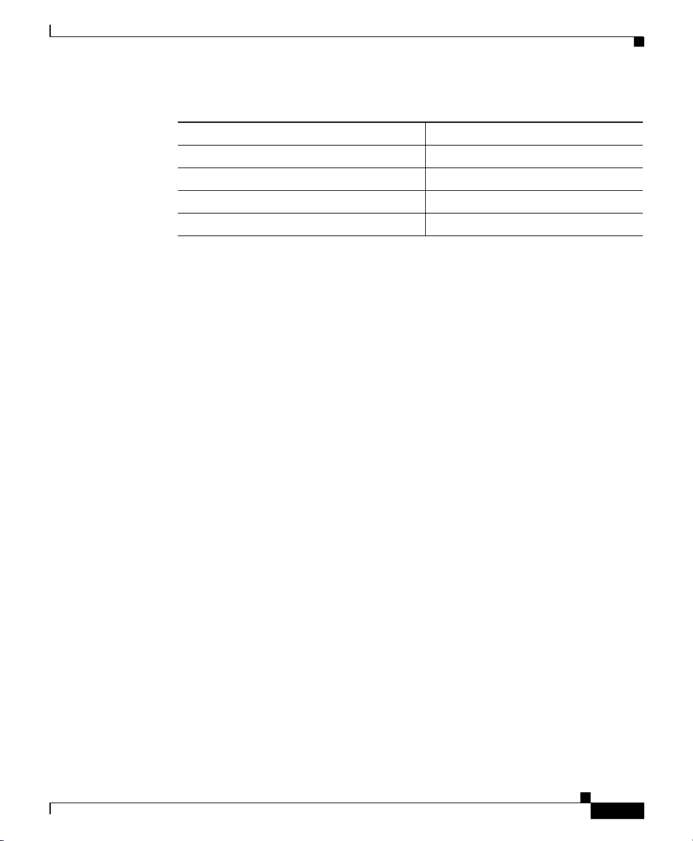
Complete the information below, and keep it for reference.
Company product purchased from
Company telephone number
Product model number
Product serial number
Maintenance contract number
78-15201-04
Cisco RPS 675 Redundant Power System Hardware Installation Guide
xi
Page 12

Cisco Limited Lifetime Hardware Warranty Terms
xii
Cisco RPS 675 Redundant Power System Hardware Installation Guide
78-15201-04
Page 13

Audience
Preface
This publication is designed for people who have some experience installing
networking equipment such as routers, hubs, servers, and switches. We assume
the person installing and troubleshooting the RPS 675 is familiar with electronic
circuitry and wiring practices and has experience as an electronic or
electromechanical technician.
Purpose
78-15201-04
This guide documents the hardware features of the Cisco Redundant Power
System (RPS) 675. It describes the physical and performance characteristics of
the RPS 675, explains how to install the RPS, and provides troubleshooting
information.
The RPS 675 provides redundant power for a number of products. Switches in the
Catalyst 2950 and Catalyst 3550 families are supported by the Cisco RPS 675
redundant power system (model
does not support the Catalyst 3550-24-DC switches.
To determine if your switch can use the RPS 675, refer to your switch
documentation or to the online RPS 675 Switch Compatibility Matrix (posted with
the RPS
supported products.
675 documentation on www.cisco.com) for the latest complete list of
Cisco RPS 675 Redundant Power System Hardware Installation Guide
PWR675-AC-RPS-N1=). The Cisco RPS 675
xiii
Page 14
Organization
This guide is organized into the following chapters:
• Chapter 1, “Product Overview,” is a physical and functional overview of the
• Chapter 2, “Installation,” contains the procedures on how to install the
• Chapter 3, “Troubleshooting,” describes how to identify and resolve some of
• Appendix A, “Technical Specifications,” lists the RPS 675 physical and
• Appendix B, “Connector and Cable Specifications,” describes the
• Appendix C, “Translated Safety Warnings,” contains translations in various
Preface
Cisco RPS 675 redundant power system. It describes the features, the LEDs
and includes examples of how the Cisco RPS 675 could be deployed.
RPS 675 on a rack, table, or shelf, and how to connect the RPS 675 to
supported devices.
the problems that might arise when installing the switch.
environmental specifications and the regulatory agency approvals.
connectors, cables, and adapters that can be used to connect to the RPS 675.
languages for the safety warnings in this guide.
Conventions
This document uses these conventions and symbols for notes, cautions,
and
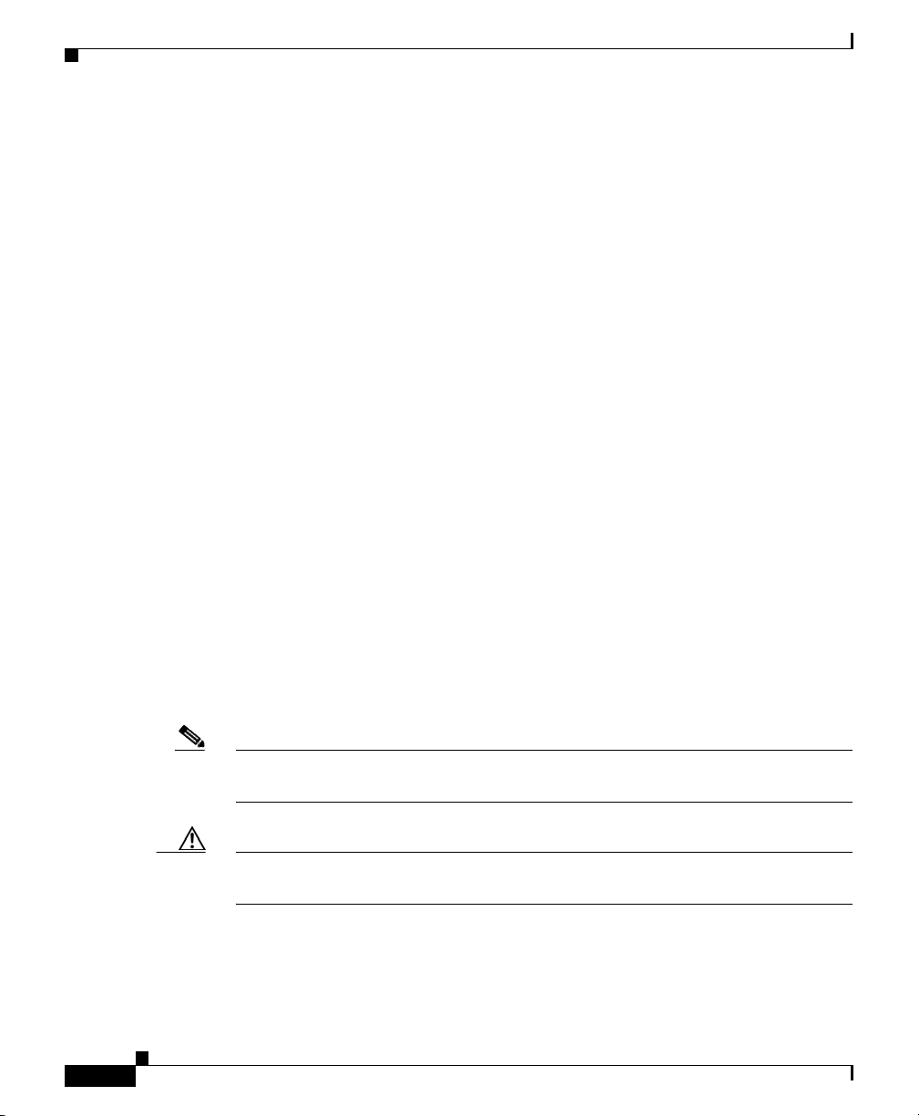
Note Means reader take note. Notes contain helpful suggestions or references to
materials not contained in this manual.
Caution Means reader be careful. In this situation, you might do something that could
result in equipment damage or loss of data.
Cisco RPS 675 Redundant Power System Hardware Installation Guide
xiv
warnings:
78-15201-04
Page 15

Preface
Statement 1071—Warning Definition
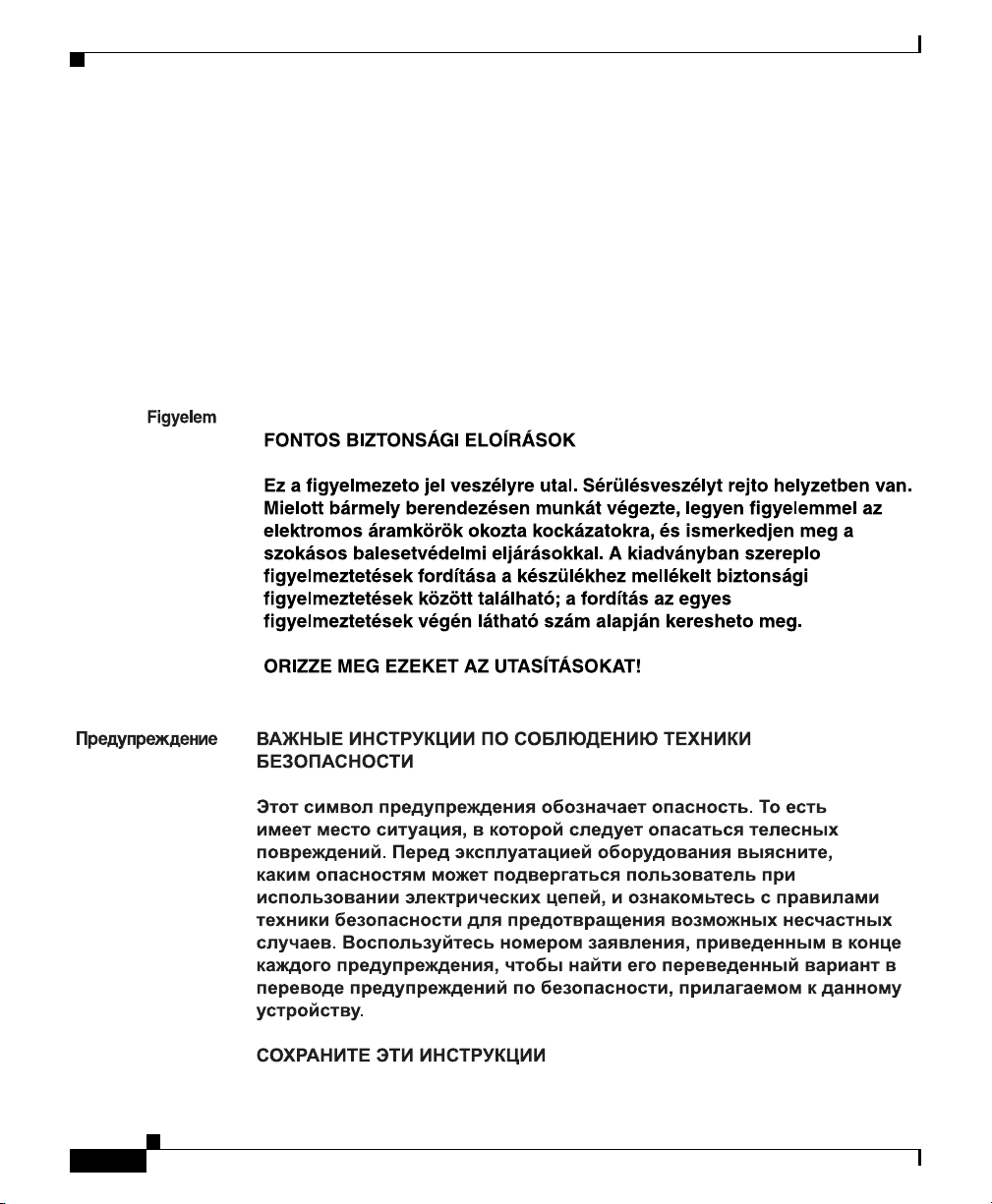
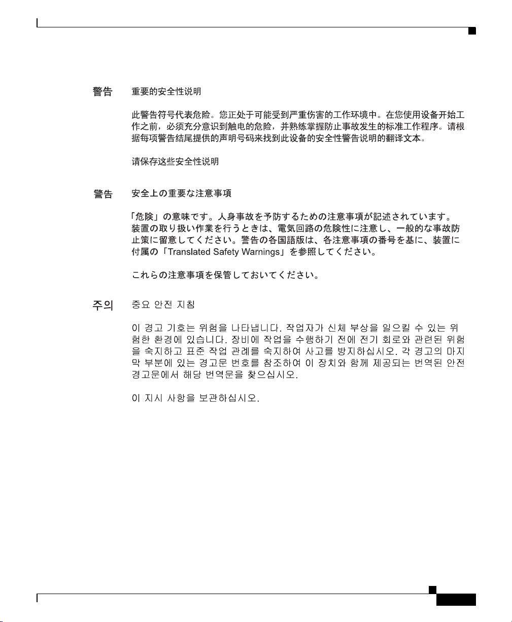
Warning
Waarschuwing
Varoitus
IMPORTANT SAFETY INSTRUCTIONS
This warning symbol means danger. You are in a situation that could cause
bodily injury. Before you work on any equipment, be aware of the hazards
involved with electrical circuitry and be familiar with standard practices for
preventing accidents. Use the statement number provided at the end of each
warning to locate its translation in the translated safety warnings that
accompanied this device.
SAVE THESE INSTRUCTIONS
BELANGRIJKE VEILIGHEIDSINSTRUCTIES
Dit waarschuwingssymbool betekent gevaar. U verkeert in een situatie die
lichamelijk letsel kan veroorzaken. Voordat u aan enige apparatuur gaat
werken, dient u zich bewust te zijn van de bij elektrische schakelingen
betrokken risico's en dient u op de hoogte te zijn van de standaard praktijken
om ongelukken te voorkomen. Gebruik het nummer van de verklaring
onderaan de waarschuwing als u een vertaling van de waarschuwing die bij
het apparaat wordt geleverd, wilt raadplegen.
BEWAAR DEZE INSTRUCTIES
TÄRKEITÄ TURVALLISUUSOHJEITA
Tämä varoitusmerkki merkitsee vaaraa. Tilanne voi aiheuttaa ruumiillisia
vammoja. Ennen kuin käsittelet laitteistoa, huomioi sähköpiirien
käsittelemiseen liittyvät riskit ja tutustu onnettomuuksien yleisiin
ehkäisytapoihin. Turvallisuusvaroitusten käännökset löytyvät laitteen
mukana toimitettujen käännettyjen turvallisuusvaroitusten joukosta
varoitusten lopussa näkyvien lausuntonumeroiden avulla.
Statement 1071
78-15201-04
SÄILYTÄ NÄMÄ OHJEET
Cisco RPS 675 Redundant Power System Hardware Installation Guide
xv
Page 16

Preface
Attention
Warnung
Avvertenza
IMPORTANTES INFORMATIONS DE SÉCURITÉ
Ce symbole d'avertissement indique un danger. Vous vous trouvez dans une
situation pouvant entraîner des blessures ou des dommages corporels. Avant
de travailler sur un équipement, soyez conscient des dangers liés aux circuits
électriques et familiarisez-vous avec les procédures couramment utilisées
pour éviter les accidents. Pour prendre connaissance des traductions des
avertissements figurant dans les consignes de sécurité traduites qui
accompagnent cet appareil, référez-vous au numéro de l'instruction situé à la
fin de chaque avertissement.
CONSERVEZ CES INFORMATIONS
WICHTIGE SICHERHEITSHINWEISE
Dieses Warnsymbol bedeutet Gefahr. Sie befinden sich in einer Situation, die
zu Verletzungen führen kann. Machen Sie sich vor der Arbeit mit Geräten mit
den Gefahren elektrischer Schaltungen und den üblichen Verfahren zur
Vorbeugung vor Unfällen vertraut. Suchen Sie mit der am Ende jeder Warnung
angegebenen Anweisungsnummer nach der jeweiligen Übersetzung in den
übersetzten Sicherheitshinweisen, die zusammen mit diesem Gerät
ausgeliefert wurden.
BEWAHREN SIE DIESE HINWEISE GUT AUF.
IMPORTANTI ISTRUZIONI SULLA SICUREZZA
xvi
Questo simbolo di avvertenza indica un pericolo. La situazione potrebbe
causare infortuni alle persone. Prima di intervenire su qualsiasi
apparecchiatura, occorre essere al corrente dei pericoli relativi ai circuiti
elettrici e conoscere le procedure standard per la prevenzione di incidenti.
Utilizzare il numero di istruzione presente alla fine di ciascuna avvertenza per
individuare le traduzioni delle avvertenze riportate in questo documento.
CONSERVARE QUESTE ISTRUZIONI
Cisco RPS 675 Redundant Power System Hardware Installation Guide
78-15201-04
Page 17

Preface
Advarsel
Aviso
¡Advertencia!
VIKTIGE SIKKERHETSINSTRUKSJONER
Dette advarselssymbolet betyr fare. Du er i en situasjon som kan føre til skade
på person. Før du begynner å arbeide med noe av utstyret, må du være
oppmerksom på farene forbundet med elektriske kretser, og kjenne til
standardprosedyrer for å forhindre ulykker. Bruk nummeret i slutten av hver
advarsel for å finne oversettelsen i de oversatte sikkerhetsadvarslene som
fulgte med denne enheten.
TA VARE PÅ DISSE INSTRUKSJONENE
INSTRUÇÕES IMPORTANTES DE SEGURANÇA
Este símbolo de aviso significa perigo. Você está em uma situação que poderá
ser causadora de lesões corporais. Antes de iniciar a utilização de qualquer
equipamento, tenha conhecimento dos perigos envolvidos no manuseio de
circuitos elétricos e familiarize-se com as práticas habituais de prevenção de
acidentes. Utilize o número da instrução fornecido ao final de cada aviso para
localizar sua tradução nos avisos de segurança traduzidos que acompanham
este dispositivo.
GUARDE ESTAS INSTRUÇÕES
INSTRUCCIONES IMPORTANTES DE SEGURIDAD
Este símbolo de aviso indica peligro. Existe riesgo para su integridad física.
Antes de manipular cualquier equipo, considere los riesgos de la corriente
eléctrica y familiarícese con los procedimientos estándar de prevención de
accidentes. Al final de cada advertencia encontrará el número que le ayudará
a encontrar el texto traducido en el apartado de traducciones que acompaña
a este dispositivo.
78-15201-04
GUARDE ESTAS INSTRUCCIONES
Cisco RPS 675 Redundant Power System Hardware Installation Guide
xvii
Page 18
Preface
Varning!
VIKTIGA SÄKERHETSANVISNINGAR
Denna varningssignal signalerar fara. Du befinner dig i en situation som kan
leda till personskada. Innan du utför arbete på någon utrustning måste du vara
medveten om farorna med elkretsar och känna till vanliga förfaranden för att
förebygga olyckor. Använd det nummer som finns i slutet av varje varning för
att hitta dess översättning i de översatta säkerhetsvarningar som medföljer
denna anordning.
SPARA DESSA ANVISNINGAR
xviii
Cisco RPS 675 Redundant Power System Hardware Installation Guide
78-15201-04
Page 19
Preface
78-15201-04
Aviso
INSTRUÇÕES IMPORTANTES DE SEGURANÇA
Este símbolo de aviso significa perigo. Você se encontra em uma situação em
que há risco de lesões corporais. Antes de trabalhar com qualquer
equipamento, esteja ciente dos riscos que envolvem os circuitos elétricos e
familiarize-se com as práticas padrão de prevenção de acidentes. Use o
número da declaração fornecido ao final de cada aviso para localizar sua
tradução nos avisos de segurança traduzidos que acompanham o dispositivo.
GUARDE ESTAS INSTRUÇÕES
Cisco RPS 675 Redundant Power System Hardware Installation Guide
xix
Page 20
Preface
Advarsel
VIGTIGE SIKKERHEDSANVISNINGER
Dette advarselssymbol betyder fare. Du befinder dig i en situation med risiko
for legemesbeskadigelse. Før du begynder arbejde på udstyr, skal du være
opmærksom på de involverede risici, der er ved elektriske kredsløb, og du
skal sætte dig ind i standardprocedurer til undgåelse af ulykker. Brug
erklæringsnummeret efter hver advarsel for at finde oversættelsen i de
oversatte advarsler, der fulgte med denne enhed.
GEM DISSE ANVISNINGER
xx
Cisco RPS 675 Redundant Power System Hardware Installation Guide
78-15201-04
Page 21
Preface
78-15201-04
Cisco RPS 675 Redundant Power System Hardware Installation Guide
xxi
Page 22
Preface
xxii
Cisco RPS 675 Redundant Power System Hardware Installation Guide
78-15201-04
Page 23
Preface
Related Publications
For information about the devices that the Cisco RPS 675 supports, refer to the
documents for those devices. These documents are available on www.cisco.com
and include:
• The Catalyst 3750 Switch Hardware Installation Guide
• The Catalyst 3560 Switch Hardware Installation Guide
• The Catalyst 3550 Multilayer Switch Hardware Installation Guide
• The Catalyst 2970 Switch Hardware Installation Guide
• The Catalyst 2950 Switch Hardware Installation Guide
Cisco RPS 675 Redundant Power System Hardware Installation Guide
78-15201-04
xxiii
Page 24

Preface
Also refer to your switch documentation and to the online RPS 675 Switch
Compatibility Matrix (posted with the RPS 675 documentation on
www.cisco.com) for a list of the latest products supported by the RPS 675.
The
online matrix is available at this location:
http://www.cisco.com/univercd/cc/td/doc/product/lan/c3550/rps675/index.htm
Obtaining Documentation and Submitting a Service
Request
For information on obtaining documentation, submitting a service request, and
gathering additional information, see the monthly What’s
Documentation, which also lists all new and revised Cisco
documentation, at:
http://www.cisco.com/en/US/docs/general/whatsnew/whatsnew.html
Subscribe to the What’s New in Cisco Product Documentation as a Really Simple
Syndication (RSS) feed and set content to be delivered directly to your desktop using
a reader application. The RSS feeds are a free service and Cisco currently supports
RSS version 2.0.
New in Cisco Product
technical
xxiv
Cisco RPS 675 Redundant Power System Hardware Installation Guide
78-15201-04
Page 25

CHAPTER
1
Product Overview
The Cisco RPS 675 Redundant Power System (RPS), model
PWR675-AC-RPS-N1=, provides N+1 redundancy. The RPS 675 provides
seamless failover to internal power supply failures for one of up to six switches.
The RPS 675 automatically senses when a connected device has experienced an
internal power supply failure. It then begins to supply power to the device. The
RPS supplies power until the power supply of the failed device is replaced or the
device is replaced. You can then return the RPS to active mode so that it is
available to supply power to another device.
Note The RPS 675 does not support an automatic switchover to the internal power
supply. You must press the Standby/Active button on the RPS so that the switch
again uses the internal power supply.
If a connected device fails, the RPS 675 sends status information to the other
connected devices and to network management software. This status information
alerts administration that these devices are not supported until the failed device or
the power supply of the failed device is brought up or replaced. To achieve
one-to-one redundancy, you must connect each device to a different RPS 675.
78-15201-04
Note The RPS 675 is designed to provide backup for internal power supply failures of
connected device power supplies. It is not designed to act as a backup power
source that protects against losses of power due to external power outages.
We
recommend using an uninterruptable power system (UPS) as protection
against power outages.
Cisco RPS 675 Redundant Power System Hardware Installation Guide
1-1
Page 26
Features
Features
Chapter 1 Product Overview
The RPS 675 was designed to support specific Cisco products; some other Cisco
products are supported by the Cisco 675W RPS. Connectors are not
interchangeable.
Consult your switch documentation or the online RPS 675 Switch Compatibility
Matrix that is available with the RPS 675 documentation on Cisco.com for a
complete list of supported products.
This chapter provides a functional overview of the RPS 675 and includes
these
topics:
• Features, page 1-2
• Front-Panel Description, page 1-3
• Rear-Panel Description, page 1-8
• Deployment Strategies, page 1-9
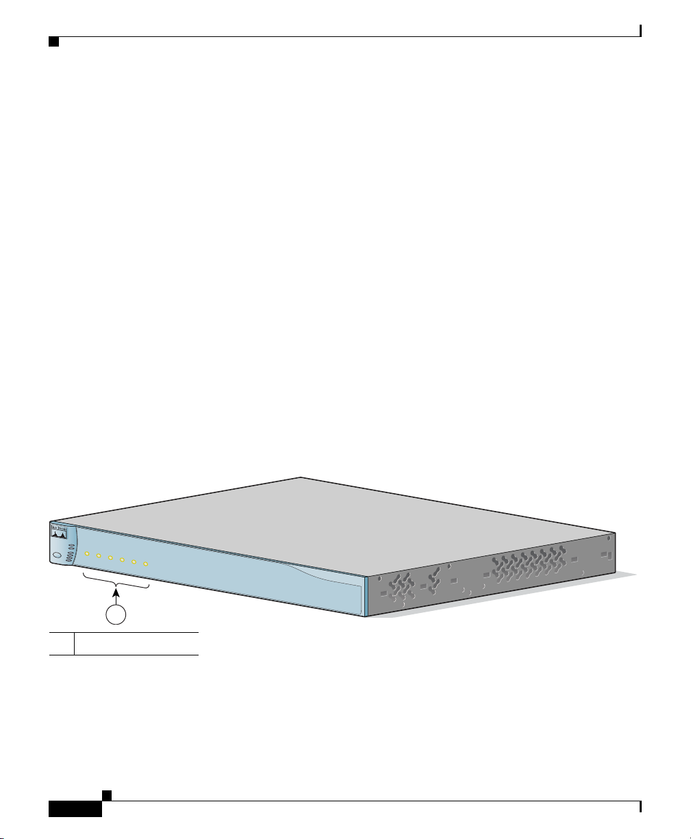
The Cisco RPS 675 is shown in Figure 1-1.
Figure 1-1 RPS 675 RPS
S
T
A
N
D
B
Y
/A
C
T
IV
E
O
U
T
P
U
T
P
W
R
T
E
M
P
F
A
N
S
T
A
N
D
B
Y
/A
C
T
IV
E
1
DC OUTPUT
234
5
6
1
1 DC output LEDs
The RPS 675 has these features:
• Six output channels to support multiple devices
• RPS status information available through the network management
application on the device
Cisco RPS 675 Redundant Power System Hardware Installation Guide
1-2
Cisco RPS 675
86663
78-15201-04
Page 27

Chapter 1 Product Overview
• Front-panel LEDs to show status for each output channel, internal power
• Quick switchover capability to ensure that the switch does not reboot if the
• Support for telephone-enabled 24-port devices
• Small form-factor suitable for rack-mounting to provide maximum wiring
• Two output levels:
• A single 48-inch (1.2-meter) 16-pin-to-14-pin connector cable
Front-Panel Description
supplies, fans, and temperature
internal switch power supply should fail
closet port density
–
–48 VDC with a maximum output of 375 W
–
12 VDC with a maximum output of 300 W
The two output levels provide a maximum total output power of 675 W.
The
–48 VDC mode powers telephone systems in Power over Ethernet (PoE)
switches.
(CAB-RPS-1614=) to allow connection to an external device. Additional
cables can be ordered separately.
Front-Panel Description
The RPS 675 front panel includes the status LEDs for the RPS and a
Standby/Active button.
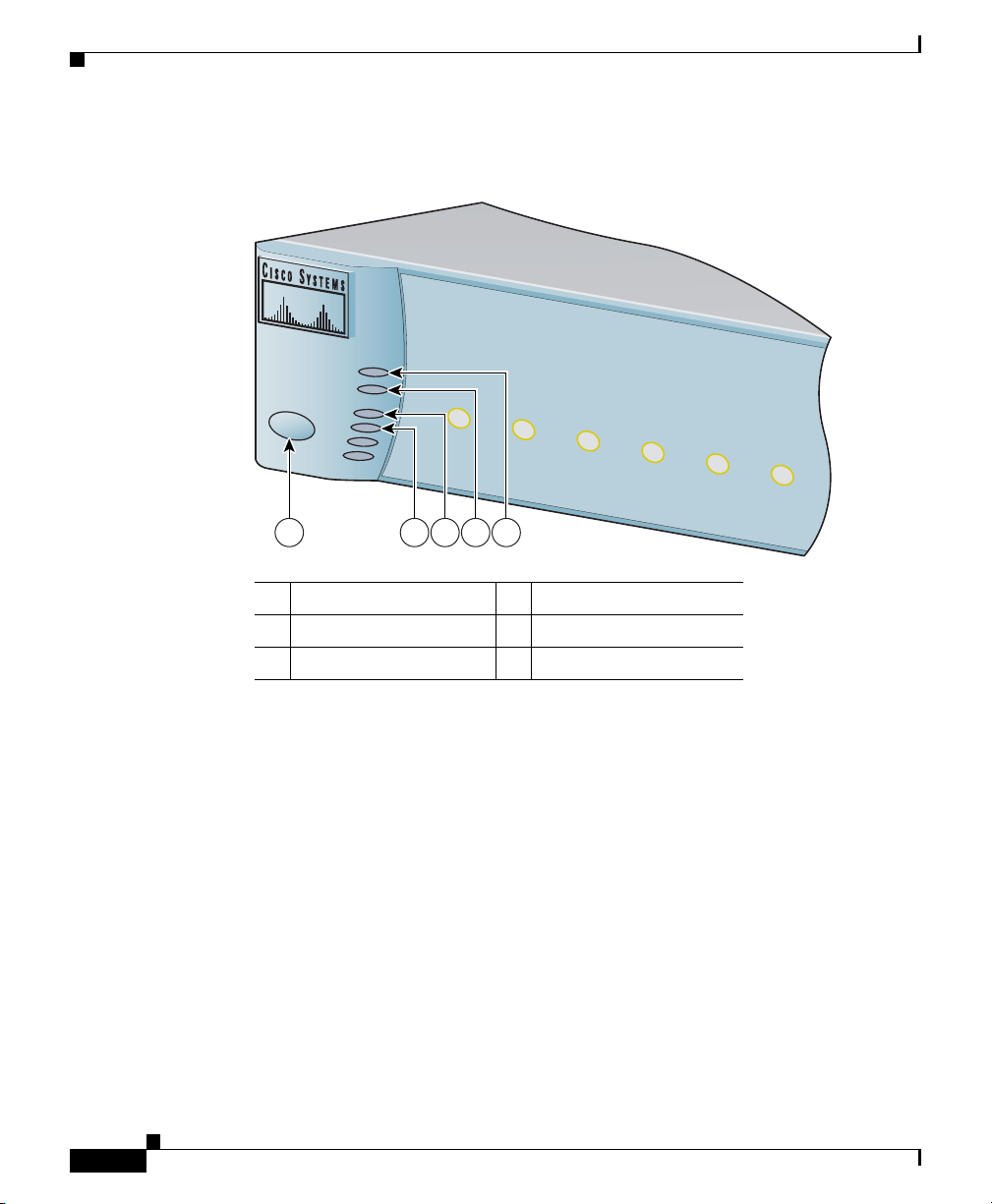
LEDs
Figure 1-2 shows the Cisco RPS 675 LEDs. The LEDs display the status of the
RPS and show whether the RPS is powering a connected device. LEDs can be off,
green, or amber.
78-15201-04
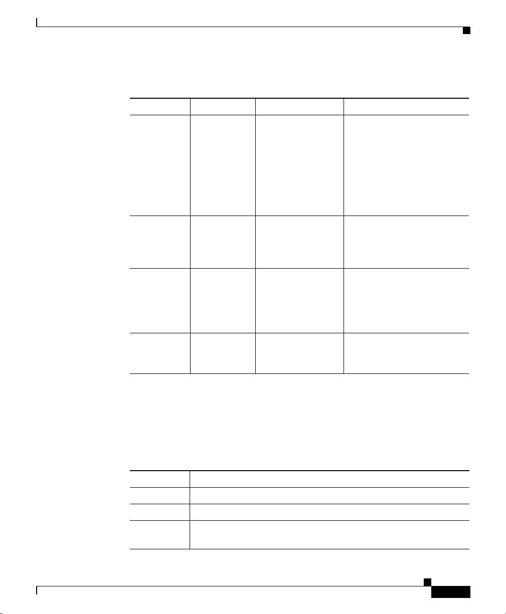
Table 1-1 lists the status LEDs and the meanings of the colors.
Cisco RPS 675 Redundant Power System Hardware Installation Guide
1-3
Page 28
Front-Panel Description
Figure 1-2 RPS 675 Front-Panel LEDs
STANDBY/ACTIVE
OUTPUT PW
R
TEM
STANDBY/ACTIVE
FAN
P
1
2
DC OUTPUT
3
Chapter 1 Product Overview
4
5
6
1 2 3 4 5
1 Standby/Active button 4 Output power LED
2 Fan LED 5 Standby/Active LED
3 Temperature LED
86666
1-4
Cisco RPS 675 Redundant Power System Hardware Installation Guide
78-15201-04
Page 29
Chapter 1 Product Overview
Ta b l e 1-1 Status LEDs
LED Off Green Amber
STANDBY/
ACTIVE
OUTPUT
PWR
TEMP The RPS 675
FAN The RPS 675
The RPS 675
is not
powered up.
The RPS 675
is not
powered up.
is not
powered up.
is not
powered up.
The RPS 675 is in
active mode and
available to
back-up a failed
device.
The RPS 675
internal power
supplies are up and
running.
The RPS 675
internal
temperature is in
the acceptable
range.
The fan (blower) is
running.
Front-Panel Description
(Blinking) The RPS is in
standby mode. You can
connect devices to the RPS,
and it does not attempt to
back them up until you
press the Standby/Active
button and place the RPS
into active mode.
The DC output power is not
functioning correctly.
The RPS 675 is approaching
an overtemperature
condition.
The blower is not operating
properly.
78-15201-04
The six DC output LEDs display the status of the six output connectors that you
use to connect to supported devices. The output LEDs are numbered 1 to 6, which
corresponds to the numbers on the DC outputs.
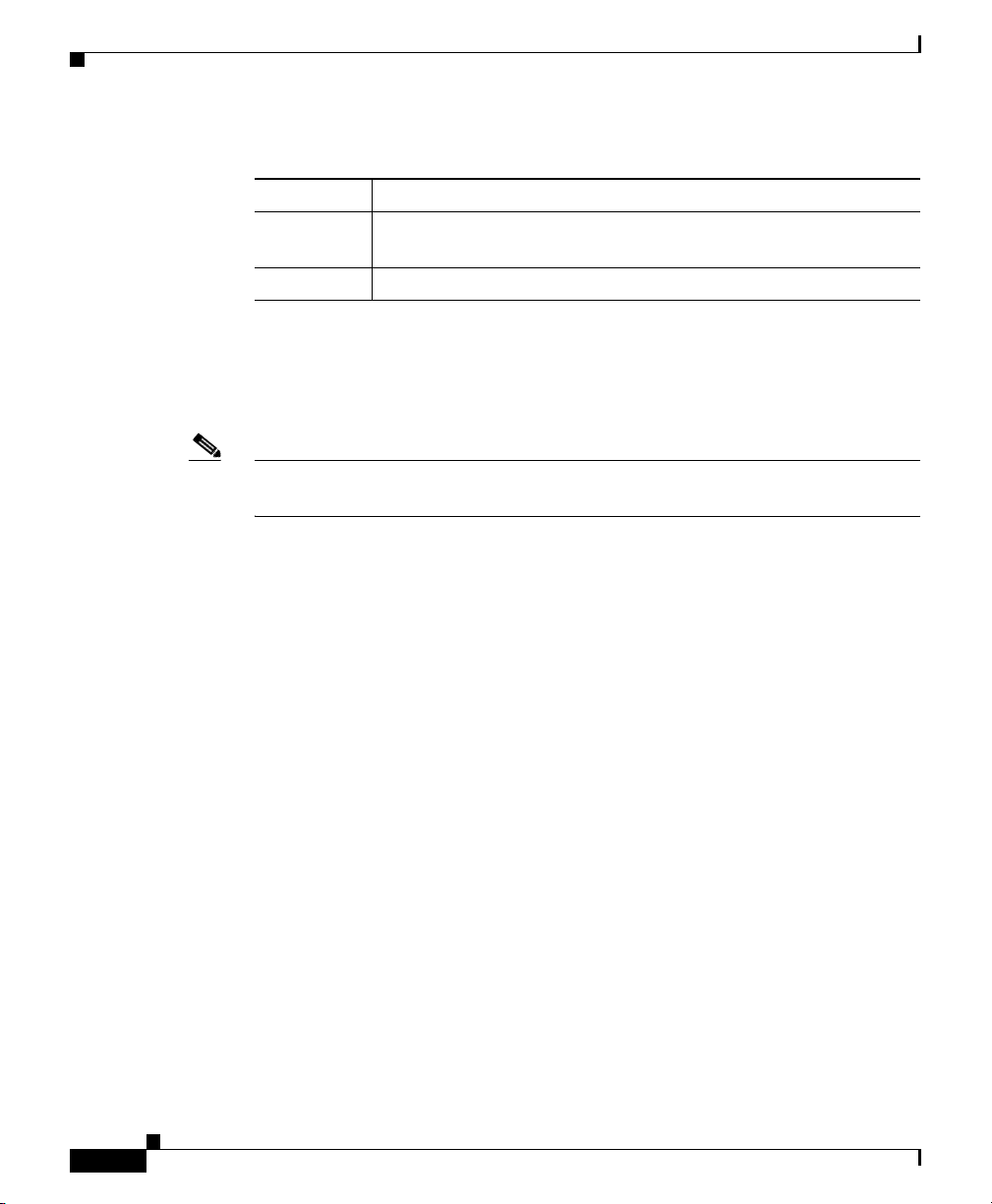
Table 1-2 lists the meanings of
the colors.
Ta b l e 1-2 DC Output LEDs
Color DC Output Status
Off No device is connected to the output connector.
Green A device is connected to the output connector.
Blinking
green
The RPS is unavailable to the connected device. The RPS is
providing power to another connected device.
Cisco RPS 675 Redundant Power System Hardware Installation Guide
1-5
Page 30
Front-Panel Description
Table 1-2 DC Output LEDs (continued)
Color DC Output Status
Blinking
amber
Amber The RPS is in standby mode or in a fault condition.
Standby/Active Button
The RPS 675 has a front panel Standby/Active button.
Note The RPS is in active mode (Standby/Active LED green) when it powers up.
It must be in standby mode every time you connect devices to it.
If you connect a device to the RPS when it is in active mode (Standby/Active LED
green), the RPS might unnecessarily begin supplying backup power to the device.
This situation might occur if you connect the device before it is powered up, or if
the RPS does not immediately sense that the device power supply was supplying
power. In this case, the RPS would not be available as a backup power source for
other connected devices.
Figure 1-3 shows the Standby/Active button. Press the Standby/Active button to
change the RPS 675 from active mode to standby mode when you connect devices.
When you change the mode to active, the Standby/Active LED turns green.
Chapter 1 Product Overview
The RPS is providing power to the connected device; the output
is active.
1-6
Cisco RPS 675 Redundant Power System Hardware Installation Guide
78-15201-04
Page 31

Chapter 1 Product Overview
Figure 1-3 Standby/Active Button
STANDBY/ACTIVE
1 Standby/Active button
STANDBY/ACTIVE
OUTPUT PW
TEM
P
FAN
1
Front-Panel Description
R
1
2
DC OUTPUT
3
4
5
6
86665
78-15201-04
When you want to connect additional devices, press the Standby/Active button to
place the RPS in standby mode. The Standby/Active LED flashes amber. When
you have connected and powered up all devices, press the Standby/Active button
again to put the RPS into active mode.
Note When the RPS is in standby mode, all of the DC Output LEDs are amber.
Note When the RPS is in standby mode, the RPS LED that is on the connected device
is amber; this means that the RPS is connected but is not functioning. When you
press the Standby/Active button, the RPS LED that is on the connected device
changes to green to show that the RPS is operating properly.
Cisco RPS 675 Redundant Power System Hardware Installation Guide
1-7
Page 32

Rear-Panel Description
Rear-Panel Description
The RPS 675 rear panel has an AC power input connector and six DC output
connectors (numbered 1 to 6) to connect to supported devices. (See
Figure 1-4 RPS 675 Rear Panel
10
0-2
40
V
~
1
2
1
V
0-6
/1
A
2
A
, -4
8
/ 7
5
0/60
.8
H
A
z
M
A
X
O
U
T
P
U
T
D
C
O
U
T
P
U
T 1
D
1
C
A
U
T
I
O
N
:
R
P
S
N
O
C
O
U
T
P
U
T
2
T
H
O
T
P
L
U
G
G
A
B
L
D
C
O
U
T
P
U
T
E
3
D
C
O
U
T
P
U
T
4
D
C
O
U
T
P
U
T
5
D
C
O
U
T
P
U
T 6
2
Chapter 1 Product Overview
Figure 1-4).
86664
3
1 AC input connector 3 Fan exhaust
2 DC output connectors
Use the supplied AC power cord to connect to an AC power outlet.
The DC output connectors require a Cisco 16-pin-to-14-pin cable
(CAB-RPS-1614=) to connect to supported devices. (One cable is supplied with
the RPS; you can order additional cables separately.) The 16-pin connector plugs
into the RPS, and the 14-pin connector plugs into the device. Use only the Cisco
cable for this connection.
Warning
Cisco RPS 675 Redundant Power System Hardware Installation Guide
Attach only the Cisco RPS 675 (model PWR675-AC-RPS-N1=) to the RPS
receptacle.
Statement 100C
1-8
78-15201-04
Page 33

Chapter 1 Product Overview
Deployment Strategies
You can deploy the Cisco RPS 675 in a variety of situations with mission-critical
applications.
One application might be in a voice and data network in which switches (such as
a Catalyst 3550-24PWR or a Catalyst 3750-48PS switch) are connected to Cisco
phones and PCs. Connecting an RPS 675 to the switches can prevent voice
IP
network failures that are caused by switch failures.
Another application might be that of using traditional data 10/100/1000 Ethernet
switches that carry mission-critical data. These applications would typically use
one RPS to support one to six switches as shown in
Figure 1-5 RPS 675 Supporting a Group of Switches
Deployment Strategies
Figure 1-5.
Network
switch
Network
switch
DC out 1 DC out 6
Network
switch
RPS 675
Network
switch
Network
switch
Network
switch
86667
In this configuration, if one device has a power-supply or power-related failure,
the RPS 675 immediately begins to supply power to this device and is no longer
available as a backup power source for the other devices. The RPS sends status
information to network management software to alert the system administrator
that the other devices are not supported until the failed device or the power supply
in the failed device is repaired or replaced.
78-15201-04
Cisco RPS 675 Redundant Power System Hardware Installation Guide
1-9
Page 34

Deployment Strategies
Chapter 1 Product Overview
When the network supports mission-critical applications that require
one-to-one
ensure that each
configuration is shown in
Figure 1-6 RPS 675 Supporting One-to-One Redundancy
redundancy, an RPS 675 is connected to each supported device to
switch is always supported. This one-to-one redundant
Figure 1-6.
Network
switch
RPS 675
Network
switch
RPS 675
Network
switch
RPS 675
Network
switch
RPS 675
86668
1-10
Cisco RPS 675 Redundant Power System Hardware Installation Guide
78-15201-04
Page 35

Installation
This chapter describes how to install and connect the Cisco Redundant Power
System (RPS) 675 and includes these topics:
• Preparing for Installation, page 2-1
• Installing the Switch, page 2-8
• Connecting the RPS 675, page 2-14
Preparing for Installation
Read these sections and perform the procedures in the order that they are
presented:
• Warnings, page 2-2
• EMC Regulatory Statements, page 2-4
CHAPTER
2
78-15201-04
• Site Requirements, page 2-7
• Verifying the Package Contents, page 2-7
Cisco RPS 675 Redundant Power System Hardware Installation Guide
2-1
Page 36

Preparing for Installation
Warnings
Chapter 2 Installation
These warnings are translated into several languages in Appendix C, “Translated
Safety Warnings.”
Warning
Warning
Warning
Warning
Warning
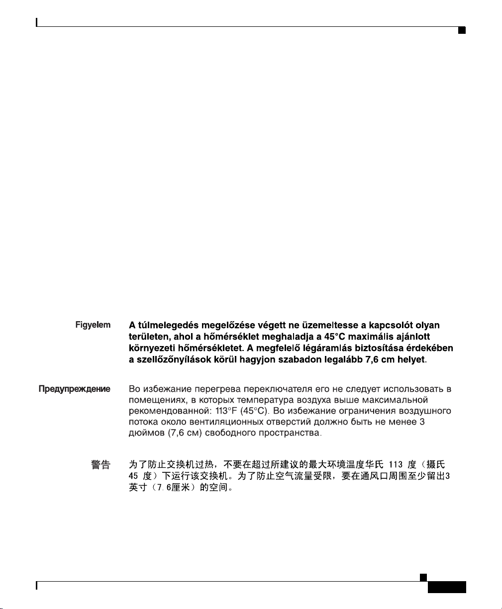
To prevent the switch from overheating, do not operate it in an area that
exceeds the maximum recommended ambient temperature of 113°F (45°C). To
prevent airflow restriction, allow at least 3
the ventilation openings.
Before working on equipment that is connected to power lines, remove jewelry
(including rings, necklaces, and watches). Metal objects will heat up when
connected to power and ground and can cause serious burns or weld the metal
object to the terminals.
Attach only the Cisco RPS (model PWR675-AC-RPS-N1) to the RPS receptacle.
Statement 100C
If a redundant power system (RPS) is not connected to the switch, install an RPS
connector cover on the back of the switch.
Do not work on the system or connect or disconnect cables during periods of
lightning activity.
Statement 1001
Statement 17B
Statement 43
inches (7.6 cm) of clearance around
Statement 265
2-2
Warning
Cisco RPS 675 Redundant Power System Hardware Installation Guide
Read the installation instructions before connecting the system to the power
source.
Statement 1004
78-15201-04
Page 37

Chapter 2 Installation
.
Preparing for Installation
Warning
Warning
Warning
To prevent bodily injury when mounting or servicing this unit in a rack, you
must take special precautions to ensure that the system remains stable. The
following guidelines are provided to ensure your safety:
• This unit should be mounted at the bottom of the rack if it is the only unit in the rack.
• When mounting this unit in a partially filled rack, load the rack from the bottom to the
top with the heaviest component at the bottom of the rack.
• If the rack is provided with stabilizing devices, install the stabilizers before mounting
or servicing the unit in the rack.
Statement 1006
This unit is intended for installation in restricted access areas. A restricted
access area can be accessed only through the use of a special tool, lock and
key, or other means of security.
Statement 1017
The plug-socket combination must be accessible at all times, because it serves
as the main disconnecting device.
Statement 1019
78-15201-04
Warning
Warning
Warning
This equipment must be grounded. Never defeat the ground conductor or
operate the equipment in the absence of a suitably installed ground conductor.
Contact the appropriate electrical inspection authority or an electrician if you
are uncertain that suitable grounding is available.
Statement 1024
Only trained and qualified personnel should be allowed to install, replace, or
service this equipment.
Statement 1030
Ultimate disposal of this product should be handled according to all national
laws and regulations.
Cisco RPS 675 Redundant Power System Hardware Installation Guide
Statement 1040
2-3
Page 38

Preparing for Installation
Chapter 2 Installation
Warning
Warning
No user-serviceable parts inside. Do not open.
Installation of the equipment must comply with local and national electrical
codes.
Statement 1074
Statement 1073
In addition, you should always follow these guidelines:
• Do not work alone if potentially hazardous conditions exist.
• Never assume that power is disconnected from a circuit. Always check.
EMC Regulatory Statements
This section includes specific regulatory statements about the Cisco 675 RPS.
U.S.A.
U.S. regulatory information for this product is in the front matter of this manual.
Statement 257—Class A Notice for Taiwan and Other Traditional Chinese Markets
2-4
Warning
Cisco RPS 675 Redundant Power System Hardware Installation Guide
This is a Class A Information Product, when used in residential environment,
it may cause radio frequency interference, under such circumstances, the
user may be requested to take appropriate countermeasures.
Statement 257
78-15201-04
Page 39

Chapter 2 Installation
Statement 191—VCCI Class A Warning for Japan
Preparing for Installation
Warning
This is a Class A product based on the standard of the Voluntary Control
Council for Interference by Information Technology Equipment (VCCI). If this
equipment is used in a domestic environment, radio disturbance may arise.
When such trouble occurs, the user may be required to take corrective
actions.
Statement 191
Statement 294—Class A Warning for Korea
Warning
This is a Class A Device and is registered for EMC requirements for industrial
use. The seller or buyer should be aware of this. If this type was sold or
purchased by mistake, it should be replaced with a residential-use type.
Statement 294
78-15201-04
Cisco RPS 675 Redundant Power System Hardware Installation Guide
2-5
Page 40

Preparing for Installation
Statement 256—Class A Warning for Hungary
Chapter 2 Installation
Warning
This equipment is a class A product and should be used and installed properly
according to the Hungarian EMC Class A requirements (MSZEN55022). Class A
equipment is designed for typical commercial establishments for which
special conditions of installation and protection distance are used.
Statement 256
This equipment is a Class A product and should be used and installed properly
according to the Hungarian EMC Class A requirements (MSZEN55022). Class A
equipment is designed for typical commercial establishments for which special
conditions of installation and protection distance are used.
Figyelmeztetés a felhasználói kézikönyv számára:
Ez a berendezés “A” osztályú termék, felhasználására és üzembe helyezésére a
magyar EMC “A” osztályú követelményeknek (MSZ EN 55022) megfeleloen
kerülhet sor, illetve ezen “A” osztályú berendezések csak megfelelo kereskedelmi
forrásból származhatnak, amelyek biztosítják a megfelelo speciális üzembe
helyezési körülményeket és biztonságos üzemelési távolságok alkalmazását.
2-6
Cisco RPS 675 Redundant Power System Hardware Installation Guide
78-15201-04
Page 41

Chapter 2 Installation
Site Requirements
Be sure to observe these requirements as you determine where to place the
Cisco
RPS:
Preparing for Installation
Warning
This unit is intended for installation in restricted access areas. A restricted
access area can be accessed only through the use of a special tool, lock and
key, or other means of security.
For proper operation, where you locate the Cisco RPS is extremely important.
If
the equipment is placed too close together, the ventilation is inadequate, and
panels are inaccessible, malfunctions and shutdowns might result, and
maintenance will be difficult.
Consider this information when you plan the location of the chassis:
• Provide for access to both the front and rear panels of the RPS 675.
• Make sure that the room where the RPS 675 operates has adequate
ventilation. Ambient air temperature might not cool equipment to acceptable
operating temperatures without adequate ventilation. See
“Technical Specifications,” for temperature requirements.
Verifying the Package Contents
Note Carefully remove the contents from the shipping container and check each item
for damage. If any item is missing or damaged, contact your Cisco representative
or reseller for support. Replace all packing material into the shipping container
and save it.
Statement 1017
Appendix A,
78-15201-04
These items are shipped:
• The RPS 675
• This Cisco RPS 675 Redundant Power System Hardware Installation Guide
• Where to Find the Catalyst Cisco RPS 675 Documentation flyer
• Product Registration Card
• AC power cord
Cisco RPS 675 Redundant Power System Hardware Installation Guide
2-7
Page 42

Installing the Switch
• One 16-pin-to-14-pin DC connector cable
• Mounting kit that contains:
–
Four rubber feet for mounting the switch on a table
–
Two mounting brackets
–
Four Phillips flat-head screws for attaching the brackets to the switch
–
Four Phillips truss-head screws for attaching the brackets to the switch
–
Four Phillips machine screws for attaching the brackets to a rack
Installing the Switch
This section describes these installation procedures:
• Table or Shelf-Mounting, page 2-8
• Rack-Mounting, page 2-9
Chapter 2 Installation
Table or Shelf-Mounting
Warning
Step 1 Unpack the RPS 675.
Step 2 Attach the rubber feet from the accessory kit into the round recesses that are
Step 3 Place the RPS 675 chassis on an appropriate table, shelf, or desktop.
Note If you have questions or need assistance, see the “Obtaining Documentation and
Cisco RPS 675 Redundant Power System Hardware Installation Guide
2-8
Do not stack the chassis on any other equipment. If the chassis falls, it can
cause severe bodily injury and equipment damage.
Follow these steps to install your chassis on a table or shelf:
located on the bottom of the chassis.
Submitting a Service Request” section on page xxiv.
Statement 48
78-15201-04
Page 43

Chapter 2 Installation
Rack-Mounting
To install the chassis in a 19-inch or 24-inch rack, follow the instructions
described in these procedures.
Note A 24-inch rack requires optional mounting hardware.
Planning Your Rack-Mount Installation
Installing the Switch
Warning
To prevent bodily injury when mounting or servicing this unit in a rack, you must
take special precautions to ensure that the system remains stable. The
following guidelines are provided to ensure your safety:
• This unit should be mounted at the bottom of the rack if it is the only unit in the rack.
• When mounting this unit in a partially filled rack, load the rack from the bottom to the
top with the heaviest component at the bottom of the rack.
• If the rack is provided with stabilizing devices, install the stabilizers before mounting
or servicing the unit in the rack.
Statement 1006
Consider this information when you plan your equipment rack installation:
• Enclosed racks must have adequate ventilation. Make sure that the rack is not
congested because each unit generates heat. The intake ports of equipment
that is located higher in the rack can draw heat upward from the equipment
that is located near the bottom of the rack. An enclosed rack should have
louvered sides and a fan to provide cooling air.
• When mounting a chassis in an open rack, make sure that the rack frame does
not block the intake or exhaust ports. If the chassis is installed on slides,
check the position of the chassis when it is seated in the rack.
• Baffles can isolate exhaust air from intake air, which also helps to draw
cooling air through the chassis. The best placement of the baffles depends on
the airflow patterns in the rack, which you can determine by experimenting
with different configurations.
78-15201-04
Cisco RPS 675 Redundant Power System Hardware Installation Guide
2-9
Page 44

Installing the Switch
• When equipment installed in a rack (particularly in an enclosed rack) fails,
try this test: Operate the equipment by itself, if possible. Power off other
equipment in the rack and in adjacent racks to allow the unit under test a
maximum of cooling air and clean power.
• Install the RPS 675 and the external devices to which it will connect in
adjacent shelves in a rack.
Tools and Equipment Required
To rack-mount the RPS 675, you need these tools and equipment:
• Number 12 Phillips screwdriver
• Number 8 Phillips screwdriver
• Screws for attaching the brackets to the RPS and the RPS to the rack
• Rack-mount brackets (19-inch or 24-inch) from the accessory kit
Attaching the Brackets to the RPS
Chapter 2 Installation
2-10
The bracket orientation and the screws that you use depend on whether you are
attaching the brackets for a 19-inch or a 24-inch rack. Use two of the supplied
screws to attach each bracket, according to the following guidelines:
• For a 19-inch rack, use the supplied number-8 Phillips flat-head screws to
attach the long side of the bracket to the RPS.
• For a 24-inch rack, use the supplied number-8 Phillips truss-head screws to
attach the short side of the bracket to the RPS.
Note If you install the switch in a 24-inch rack, an optional bracket kit that is not
included with the switch is required. You can order a kit that contains the 24-inch
rack-mounting brackets and hardware from Cisco (part number
RCKMNT-1RU=).
You can install the RPS into a rack with either the front panel or the rear panel
facing
forward.
Cisco RPS 675 Redundant Power System Hardware Installation Guide
78-15201-04
Page 45
Chapter 2 Installation
Note If you plan to use the optional cable guide, you should mount the RPS with the
Installing the Switch
rear panel forward.
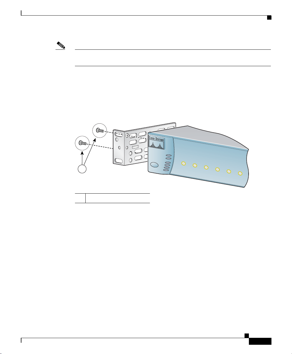
Figure 2-1 through Figure 2-4 show how to attach a bracket to one side of the RPS
for installation into 19-inch or 24-inch racks with the front panel or rear panel of
the RPS facing forward. Follow the same steps to attach the second bracket to the
opposite side.
Figure 2-1 Attaching Brackets for 19-Inch Racks (Front Panel Forward)
S
T
A
N
D
B
Y
/A
C
T
IV
E
O
U
T
P
U
T
P
W
R
T
E
M
P
F
A
N
S
T
A
N
D
B
Y
/A
C
T
IV
1
E
1
2
DC OUTPUT
3
4
5
6
78-15201-04
86672
1 Phillips flat-head screws
Cisco RPS 675 Redundant Power System Hardware Installation Guide
2-11
Page 46

Installing the Switch
Chapter 2 Installation
Figure 2-2 Attaching Brackets for 19-Inch Racks (Rear Panel Forward)
DC
OU
TPUT 6
1 Phillips flat-head screws
1 Phillips flat-head screws
Figure 2-3 Attaching Brackets for 24-Inch Racks (Front Panel Forward)
S
T
A
N
D
B
Y
/A
C
T
IV
E
O
U
T
P
U
T
P
W
R
T
E
M
P
F
A
1
N
S
T
A
N
D
B
Y
/A
C
T
IV
E
1
2
DC OUTPUT
3
4
5
1 Phillips flat-head screws
1
86688
6
86689
2-12
Cisco RPS 675 Redundant Power System Hardware Installation Guide
78-15201-04
Page 47

Chapter 2 Installation
Installing the Switch
Figure 2-4 Attaching Brackets for 24-Inch Racks (Rear Panel Forward)
DC
OU
TPUT 6
1 Phillips flat-head screws
1
86690
78-15201-04
Cisco RPS 675 Redundant Power System Hardware Installation Guide
2-13
Page 48

Connecting the RPS 675
Mounting the RPS in a Rack
After the brackets are attached to the RPS, use the four supplied number-12
Phillips machine screws to securely attach the brackets to the rack, as shown in
Figure 2-5.
Figure 2-5 Mounting the RPS in a Rack
STANDBY/ACTIVE
OUTPUT PWR
TEMP
FAN
STANDBY/ACTIVE
1
D
C
O
U
T
1
P
U
T
2
3
4
5
6
1
Chapter 2 Installation
Cisco RPS 300
86676
1 Phillips machine screws
Connecting the RPS 675
Caution Make sure that the RPS is either in standby mode or that the RPS AC power is
disconnected before you connect the RPS to a switch. This precaution is necessary
because when you connect the RPS to the AC power, the RPS automatically
becomes active.
Note Do not use different power sources to power up the RPS and the connected device.
If you connect to separate AC power sources, reset conditions might occur.
Cisco RPS 675 Redundant Power System Hardware Installation Guide
2-14
78-15201-04
Page 49

Chapter 2 Installation
Note The switch might restart when it changes from RPS power to its own internal
Connecting the RPS 675
power. This situation might occur after the power supply on a switch fails, the
RPS takes over, and the switch reverts to its own power. We advise you to assume
this possibility and plan accordingly when you restart a switch using its internal
power after using the RPS as backup power.
Warning
Before working on a system that has an on/off switch, turn OFF the power and
unplug the power cord.
Statement 1
With the RPS 675 on a desktop or in a rack, connect devices as follows:
Step 1 If the RPS is already connected to AC power, press the Standby/Active button on
the RPS to put it into standby mode or disconnect the RPS from the AC power. If
you pressed the Standby/Active button, the Standby/Active LED should begin
blinking amber. If the Standby/Active LED does not blink amber, see
Chapter 3,
“Troubleshooting.”
Step 2 Connect one end of an RPS connector cable (CAB-RPS-1614=) to an RPS DC
output connector. See
Figure 2-6. To ensure proper operation, be sure that you
completely seat the connector and that you securely tighten the screw.
Note The connector is designed to be inserted into the receptacle in its correct
orientation.
78-15201-04
Cisco RPS 675 Redundant Power System Hardware Installation Guide
2-15
Page 50

Connecting the RPS 675
Figure 2-6 Connecting the Cable to the RPS 675
1
00
-24
0
V~
1
1
2
0
V
-6
A
/2
5
A
,
-4
8
V
5
/
0/6
7
.8
0H
A
z
M
A
X
O
U
T
P
U
T
D
C
O
U
T
PU
T
1
D
C
OU
T
C
A
U
T
IO
N
:
R
P
UT
2
P
S
N
O
T
H
O
T
P
L
U
G
G
A
B
L
D
C
O
U
T
P
UT
E
3
D
C
O
U
T
P
U
T
4
D
C
O
U
T
P
U
T 5
D
C
O
U
T
P
UT
6
Chapter 2 Installation
86669
Warning
Attach only the Cisco RPS (model PWR675-AC-RPS-N1) to the RPS receptacle.
Statement 100C
Step 3 Connect the other end of the RPS connector cable to the RPS receptacle on
the
switch.
Step 4 Repeat Step 2 through Step 3 for each switch that the RPS 675 will support.
Step 5 Connect all supported devices to an AC power source.
Note The RPS 675 is designed to provide backup for internal power supply
failures of connected device power supplies. It is not designed to act as a
backup power source that protects against losses of power due to external
power outages. We recommend using an uninterruptable power system
(UPS) as protection against power outages.
Step 6 If the RPS is not already connected to AC power, connect the AC power cable to
the RPS 675 as shown in
Figure 2-7, and connect the other end of the power cable
to an AC power source.
2-16
Cisco RPS 675 Redundant Power System Hardware Installation Guide
78-15201-04
Page 51

Chapter 2 Installation
Figure 2-7 Connecting the AC Cable to the RPS 675
Connecting the RPS 675
100-240V~
10-6A
50/60Hz
12V /25A, -48V /7.8A M
DC O
U
TPUT 1
AX OU
TPUT
DC O
Step 7 Press the RPS Standby/Active button to put the RPS into active mode.
The Standby/Active, Output Power, Temperature, and Fan LEDs on the RPS front
panel should be green. The DC Output LEDs for the connected devices should
also be green. If they are not green, see
Table 3-1 on page 3-1 for the appropriate
action to take.
UTPU
T 2
86670
78-15201-04
Cisco RPS 675 Redundant Power System Hardware Installation Guide
2-17
Page 52

Connecting the RPS 675
Chapter 2 Installation
2-18
Cisco RPS 675 Redundant Power System Hardware Installation Guide
78-15201-04
Page 53

CHAPTER
3
Troubleshooting
The Cisco Redundant Power System (RPS) 675 is not repairable in the field.
Table 3-1 shows the appropriate action to take for specific LED indications.
Ta b l e 3-1 LED Indications and Appropriate Action
Symptom Condition Action
Standby/Active
LED is blinking
amber.
Standby/Active
LED is off.
Output Power
LED is amber.
Temperature
LED is amber.
The RPS is in standby
mode.
The AC power
connection to one or
both of the internal
power supplies is
faulty or not
connected.
The DC output power
from the internal
power supplies is not
available or is not
functioning correctly.
The RPS 675 is
approaching an
overtemperature
condition.
Press the Standby/Active button to
put the RPS in active mode.
Check the AC power connection to
external power.
If the AC power is connected
properly, the problem might be with
the RPS internal power supplies.
An internal power supply is
defective, or the RPS has reacted to
an overcurrent condition. Press the
Standby/Active button. If the LED
color does not turn green, replace the
RPS 675.
Reduce the ambient temperature.
78-15201-03
Cisco RPS 675 Redundant Power System Hardware Installation Guide
3-1
Page 54

Chapter 3 Troubleshooting
Table 3-1 LED Indications and Appropriate Action (continued)
Symptom Condition Action
Fan (blower)
LED is amber.
One or more DC
Output LEDs are
blinking green.
One or more DC
Output LEDs are
solid amber.
The blower is not
operating properly.
The RPS is
unavailable to the
connected device. It
is either providing
power to another
connected device or a
fault condition exists.
The RPS is in standby
mode.
The fan is defective. Replace the
RPS
675.
Verify that the RPS is supplying
power to one device. If so, this is a
normal indication and will change
when that external device is again
supplying its own power and you
press the Standby/Active button.
Press the Standby/Active button to
put the RPS into active (or ready)
mode.
3-2
Cisco RPS 675 Redundant Power System Hardware Installation Guide
78-15201-03
Page 55

APPENDIX
A
Technical Specifications
Table A-1 lists the technical specifications for the Cisco Redundant Power System
(RPS) 675 (model PWR675-AC-RPS-N1=). Ta b le A-2 lists the agency approvals.
Ta b l e A-1 Technical Specifications for the RPS 675
Environmental Ranges
Operating temperature 32 to 113°F (0 to 45°C)
Storage temperature –4 to 149°F (–20 to 65°C)
Operating humidity 10 to 85% (noncondensing)
Storage humidity 5 to 95% (noncondensing)
Operating altitude Up to 10,000 ft (3,000 m)
Storage altitude Up to 15,000 ft (4,570 m)
Power Requirements
AC input voltage 100 to 240 VAC (autoranging)
6 to 10 A, 50 to 60 Hz
875 W
Power delivery (available
power)
To t al
Standby power
KVA 0.875 KVA
1
375 W per –48 VDC output and
300 W per 12 VDC output
25 W
78-15201-04
Cisco RPS 675 Redundant Power System Hardware Installation Guide
A-1
Page 56

Appendix A Technical Specifications
Table A-1 Technical Specifications for the RPS 675 (continued)
Physical Dimensions
Weight 13 lb. (5.9 kg)
Dimensions (H x W x D) 1.75 x 17.5 x 14.88 in.
(4.45 x 44.45 x 37.8 cm)
1. Power consumption when the power supply unit is inactive.
Ta b l e A-2 RPS 675 Redundant Power System Agency Approvals
Safety EMC
UL 60950 FCC Part 15 Class A
CAN/CSA 22.2 No. 60950 BSMI
IEC 60950/EN 60950 EN 55022: 1998 (CISPR22) Class A
AS/NZS 3260, TS001 EN 55024: 1998 (CISPR24)
CE VCCI Class A
CCC approval pending AS/NZS 3548 Class A
CLEI code CE
NOM CNS 13438 Class A
MIC
A-2
Cisco RPS 675 Redundant Power System Hardware Installation Guide
78-15201-04
Page 57

APPENDIX
B
Connector and Cable Specifications
This appendix describes the cable connector that is used to connect the Cisco
Redundant Power System (RPS) 675 to a supported device. The cable
(CAB-RPS-1614=) is a 48-inch (1.2-meter) cable with a 16-pin connector on one
end and a 14-pin connector on the other end.
connectors, and Table B-1 contains the pinout information.
Note The connector is keyed to insert into the receptacle only in its correct orientation.
Figure B-1 14-Pin Connector Pinouts
Top of Connector (Logo Side)
14 13 12 11 10 9 8
Figure B-1 and Figure B-2 show the
78-15201-04
1234567
50211
Cisco RPS 675 Redundant Power System Hardware Installation Guide
B-1
Page 58

Appendix B Connector and Cable Specifications
Figure B-2 16-Pin Connector Pinouts
Top of Connector (Logo Side)
9 101112131415
1234567168
86671
Ta b l e B-1 14-Pin and 16-Pin Connector Pinout
Pin Number 14-Pin Designation 16-Pin Designation
1 GND GND–48 V
2 –48 V –48 V
3 12 V 12 V
4 12 V 12 V
5 12 V 12 V
6 12 V 12 V
7 GND GND–12
8 GND GND–12
9 –48 V GND–48 V
10 RPS_PRES (RPS present) –48 V
11 RPS_CTRL 0 RPS_PRES (RPS present)
12 RPS_CTRL 1 RPS_CTRL 0
13 PWR_GOOD (power is good) RPS_CTRL 1
14 GND PWR_GOOD (power is good)
15 GND–12
16 GND–12 V
B-2
Cisco RPS 675 Redundant Power System Hardware Installation Guide
78-15201-04
Page 59

APPENDIX
C
Translated Safety Warnings
This appendix repeats in multiple languages the warnings in this guide. These
warning statements and their translations are included:
• Statement 17B—Overtemperature Warning, page C-2
• Statement 43—Jewelry Removal Warning, page C-5
• Statement 48—Stacking the Chassis Warning, page C-7
• Statement 100C—Attaching the Cisco RPS (model PWR675-AC-RPS-N1),
page C-9
• Statement 265—Redundant Power Supply Connection Warning, page C-10
• Statement 1001—Work During Lightning Activity, page C-12
• Statement 1004—Installation Instructions, page C-13
• Statement 1006—Chassis Warning for Rack-Mounting and Servicing,
page C-15
• Statement 1017—Restricted Area, page C-25
78-15201-04
• Statement 1019—Main Disconnecting Device, page C-28
• Statement 1024—Ground Conductor, page C-30
• Statement 1030—Equipment Installation, page C-34
• Statement 1040—Product Disposal, page C-36
• Statement 1073—No User-Serviceable Parts, page C-38
• Statement 1074—Comply with Local and National Electrical Codes,
page C-41
Cisco RPS 675 Redundant Power System Hardware Installation Guide
C-1
Page 60

Appendix C Translated Safety Warnings
Statement 17B—Overtemperature Warning
Statement 17B—Overtemperature Warning
Warning
Waarschuwing
Varoitus
Attention
Warnung
To prevent the switch from overheating, do not operate it in an area that
exceeds the maximum recommended ambient temperature of 113°F (45°C). To
prevent airflow restriction, allow at least 3
around the ventilation openings.
Om oververhitting van de schakelaar te voorkomen, mag u die niet bedienen
in een ruimte die de maximale aanbevolen omgevingstemperatuur van 113°F
(45°C) overschrijdt. Om beperking van de luchtstroom te voorkomen, dient u
ten minste 3 inch (7,6 cm) speling te laten rondom de ventilatie-openingen.
Estääksesi kytkimen ylikuumenemisen älä käytä sitä sellaisissa paikoissa,
joiden lämpötila ylittää ympäristön enimmäislämpötilaksi suositellun 45°C.
Jätä vähintään 7,6 cm:n vapaa tila tuuletusaukkojen ympärille, jotta ilma
pääsee vapaasti virtaamaan.
Pour éviter une surchauffe du commutateur, ne pas le faire fonctionner dans
un local dont la température ambiante dépasse le maximum recommandé de
45°C (113°F). Pour faciliter la circulation d'air, aménager un dégagement d'au
moins 7,6
Um eine Überhitzung des Schalters zu vermeiden, ist das System nicht in
einem Bereich zu betreiben, in dem die empfohlene Höchsttemperatur von
45°C überschritten wird. Damit der Luftfluß nicht behindert wird, ist ein
Freiraum von mindestens 7,6 cm um die Belüftungsöffnungen herum
einzuhalten.
cm (3 pouces) autour des bouches d'aération.
Statement 17B
inches (7.6 cm) of clearance
C-2
Avvertenza
Cisco RPS 675 Redundant Power System Hardware Installation Guide
Per evitare il surriscaldamento dell’interruttore, non usare l'apparecchiatura
in un’area che supera la temperatura ambientale minima consigliata di 45°C.
Per evitare una limitazione del flusso dell’aria, lasciare come minimo uno
spazio libero di 7,6 cm intorno alle aperture di ventilazione.
78-15201-04
Page 61
Appendix C Translated Safety Warnings
Statement 17B—Overtemperature Warning
Advarsel
Aviso
¡Advertencia!
Varning!
For å unngå at bryteren overopphetes skal utstyret ikke brukes på steder hvor
anbefalt maks omgivelsestemperatur overstiger 113 grader Farenheit (45°C).
La det være minst 3 tommer (7,6 cm) klaring rundt ventilasjonsåpningene for
at luftsirkulasjonen skal være uhindret.
Para evitar sobreaquecimento do interruptor, não utilize o equipamento numa
àrea que exceda uma temperatura máxima de 45°C. Para evitar o
bloqueamento da circulação de ar, deixe pelo menos um espaço de 7.6 cm em
volta das aberturas de ventilação.
Para evitar que el interruptor se recaliente, no se debe usar en áreas cuya
temperatura ambiente exceda la máxima recomendada, esto es, 45°C (113°F).
Para no entorpecer la corriente de aire, dejar por lo menos 7,6 cm (3 pulgadas)
de espacio muerto alrededor de la rejilla de ventilación.
I syfte att undvika överhettning av switchen skall den inte användas i
utrymmen vars temperatur överskrider den maximalt rekommenderade
omgivningstemperaturen som är 45°C. Kontrollera att det finns minst 7,6 cm
fritt utrymme runt ventilationsöppningarna så att luftflödet inte begränsas.
78-15201-04
Cisco RPS 675 Redundant Power System Hardware Installation Guide
C-3
Page 62

Statement 17B—Overtemperature Warning
Appendix C Translated Safety Warnings
C-4
Cisco RPS 675 Redundant Power System Hardware Installation Guide
78-15201-04
Page 63

Appendix C Translated Safety Warnings
Statement 43—Jewelry Removal Warning
Statement 43—Jewelry Removal Warning
Warning
Waarschuwing
Varoitus
78-15201-04
Before working on equipment that is connected to power lines, remove
jewelry (including rings, necklaces, and watches). Metal objects will heat up
when connected to power and ground and can cause serious burns or weld the
metal object to the terminals.
Alvorens aan apparatuur te werken die met elektrische leidingen is
verbonden, sieraden (inclusief ringen, kettingen en horloges) verwijderen.
Metalen voorwerpen worden warm wanneer ze met stroom en aarde zijn
verbonden, en kunnen ernstige brandwonden veroorzaken of het metalen
voorwerp aan de aansluitklemmen lassen.
Ennen kuin työskentelet voimavirtajohtoihin kytkettyjen laitteiden parissa,
ota pois kaikki korut (sormukset, kaulakorut ja kellot mukaan lukien).
Metalliesineet kuumenevat, kun ne ovat yhteydessä sähkövirran ja maan
kanssa, ja ne voivat aiheuttaa vakavia palovammoja tai hitsata metalliesineet
kiinni liitäntänapoihin.
Cisco RPS 675 Redundant Power System Hardware Installation Guide
Statement 43
C-5
Page 64

Statement 43—Jewelry Removal Warning
Appendix C Translated Safety Warnings
Attention
Warnung
Avvertenza
Advarsel
Aviso
Avant d’accéder à cet équipement connecté aux lignes électriques, ôter tout
bijou (anneaux, colliers et montres compris). Lorsqu’ils sont branchés à
l’alimentation et reliés à la terre, les objets métalliques chauffent, ce qui peut
provoquer des blessures graves ou souder l’objet métallique aux bornes.
Vor der Arbeit an Geräten, die an das Netz angeschlossen sind, jeglichen
Schmuck (einschließlich Ringe, Ketten und Uhren) abnehmen.
Metallgegenstände erhitzen sich, wenn sie an das Netz und die Erde
angeschlossen werden, und können schwere Verbrennungen verursachen
oder an die Anschlußklemmen angeschweißt werden.
Prima di intervenire su apparecchiature collegate alle linee di alimentazione,
togliersi qualsiasi monile (inclusi anelli, collane, braccialetti ed orologi). Gli
oggetti metallici si riscaldano quando sono collegati tra punti di
alimentazione e massa: possono causare ustioni gravi oppure il metallo può
saldarsi ai terminali.
Fjern alle smykker (inkludert ringer, halskjeder og klokker) før du skal arbeide
på utstyr som er koblet til kraftledninger. Metallgjenstander som er koblet til
kraftledninger og jord blir svært varme og kan forårsake alvorlige
brannskader eller smelte fast til polene.
Antes de trabalhar em equipamento que esteja ligado a linhas de corrente,
retire todas as jóias que estiver a usar (incluindo anéis, fios e relógios). Os
objectos metálicos aquecerão em contacto com a corrente e em contacto com
a ligação à terra, podendo causar queimaduras graves ou ficarem soldados
aos terminais.
¡Advertencia!
Varning!
C-6
Antes de operar sobre equipos conectados a líneas de alimentación, quitarse
las joyas (incluidos anillos, collares y relojes). Los objetos de metal se
calientan cuando se conectan a la alimentación y a tierra, lo que puede
ocasionar quemaduras graves o que los objetos metálicos queden soldados a
los bornes.
Tag av alla smycken (inklusive ringar, halsband och armbandsur) innan du
arbetar på utrustning som är kopplad till kraftledningar. Metallobjekt hettas
upp när de kopplas ihop med ström och jord och kan förorsaka allvarliga
brännskador; metallobjekt kan också sammansvetsas med kontakterna.
Cisco RPS 675 Redundant Power System Hardware Installation Guide
78-15201-04
Page 65

Appendix C Translated Safety Warnings
Statement 48—Stacking the Chassis Warning
Statement 48—Stacking the Chassis Warning
Warning
Waarschuwing
Varoitus
78-15201-04
Do not stack the chassis on any other equipment. If the chassis falls, it can
cause severe bodily injury and equipment damage.
Het chassis mag niet op andere apparatuur gestapeld te worden. Als het
chassis mocht vallen, kan dit ernstig lichamelijk letsel en beschadiging van
de apparatuur veroorzaken.
Älä aseta asennuspohjaa minkään muun laitteen päälle. Asennuspohja voi
pudotessaan aiheuttaa vaikean ruumiinvamman tai laitevaurion.
Cisco RPS 675 Redundant Power System Hardware Installation Guide
Statement 48
C-7
Page 66

Statement 48—Stacking the Chassis Warning
Appendix C Translated Safety Warnings
Avertissement
Achtung
Avvertenza
Advarsel
Aviso
¡Atención!
Varning
Ne placez pas ce châssis sur un autre appareil. En cas de chute, il pourrait
provoquer de graves blessures corporelles et d'importants dommages.
Das Gehäuse nicht auf andere Geräte stellen. Wenn das Gehäuse
herunterfällt, besteht Gefahr schwerer Personenverletzungen und
Geräteschäden.
Non collocare lo chassis su nessun altro apparecchio. Se lo chassis cade, può
causare lesioni gravi e danni alle apparecchiature.
Stable ikke kabinettet oppå annet utstyr. Hvis kabinettet faller, kan det
forårsake alvorlig skade på mennesker og utstyr.
Não coloque o chassis em cima de qualquer outro equipamento. Se o chassis
cair, poderá causar ferimentos graves e danos no equipamento.
No apilar los chasis sobre ningún otro equipo. Si el chasis se cae al suelo
puede causar graves lesiones físicas y daños al equipo.
Placera inte chassit ovanpå annan utrustning. Om chassit faller kan allvarlig
kroppsskada såväl som skada på utrustningen uppstå.
C-8
Cisco RPS 675 Redundant Power System Hardware Installation Guide
78-15201-04
Page 67

Appendix C Translated Safety Warnings
Statement 100C—Attaching the Cisco RPS (model PWR675-AC-RPS-N1)
Statement 100C—Attaching the Cisco RPS (model
PWR675-AC-RPS-N1)
Warning
Waarschuwing
Varoitus
Avertissement
Warnung
Avvertenza
Advarsel!
Aviso
¡Advertencia!
Varning!
Attach only the Cisco RPS (model PWR675-AC-RPS-N1) to the RPS receptacle.
Statement 100C
Slechts de Cisco RPS (model PWR675-AC-RPS-N1) aan de RPS contactdoos
verbinden.
Kiinnitä RPS-vastakappaleeseen vain Cisco RPS (malli PWR675-AC-RPS-N1).
Raccordez le bloc d’alimentation Cisco RPS (modèle PWR675-AC-RPS-N1)
uniquement au connecteur RPS.
An die RPS-Steckhülse darf nur das Cisco RPS (Modell PWR675-AC-RPS-N1)
angeschlossen werden.
Collegare soltanto il Cisco RPS (modello PWR675-AC-RPS-N1) alla presa RPS.
Koble bare Cisco RPS (modell PWR675-AC-RPS-N1) til RPS-stikkontakten.
Anexe o RPS Cisco (modelo PWR675-AC-RPS-N1) apenas ao receptáculo RPS.
Sólo conecte el Cisco RPS (modelo PWR675-AC-RPS-N1) al receptáculo RPS.
Koppla endast Ciscos RPS (modell PWR675-AC-RPS-N1) till RPS-uttaget.
78-15201-04
Cisco RPS 675 Redundant Power System Hardware Installation Guide
C-9
Page 68

Appendix C Translated Safety Warnings
Statement 265—Redundant Power Supply Connection Warning
Statement 265—Redundant Power Supply
Connection Warning
Warning
Waarschuwing
Varoitus
Attention
Warnung
Avvertenza
If a redundant power system (RPS) is not connected to the switch, install an
RPS connector cover on the back of the switch.
Als er geen redundant voedingssysteem (RPS) aan de schakelaar is
gekoppeld, dient u een RPS-connectorkapje op de achterkant van de
schakelaar te installeren.
Jos korvautuvaa tehojärjestelmää (redundant power system, RPS) ei ole
liitetty kytkimeen, kiinnitä RPS-liittimen suojus kytkimen takapuolelle.
Si un système d’alimentation électrique redondant (RPS) n’est pas connecté
au commutateur, installez un cache de connecteur RPS à l’arrière du
commutateur.
Wenn keine redundante Stromversorgung (RSV) an den Schalter
angeschlossen ist, eine RSV-Steckerabdeckung an der Rückseite des
Schalters anbringen.
Se un sistema RPS (Redundant Power System ) di alimentazione ridondante
non è collegato al dispositivo switch, installare un copri-connettore RPS sul
retro del switch.
Statement 265
C-10
Cisco RPS 675 Redundant Power System Hardware Installation Guide
78-15201-04
Page 69

Appendix C Translated Safety Warnings
Statement 265—Redundant Power Supply Connection Warning
Advarsel
Aviso
¡Advertencia!
Varning!
Dersom et redundant strømsystem ( Redundant Power System -RPS) ikke er
koblet til bryteren, skal det installeres et RPS-koblingsdeksel på baksiden av
bryteren.
Se um sistema de alimentação redundante (RPS) não estiver conectado a um
switch, instale uma capa de conector RPS na parte de trás do switch.
Si no se conecta un sistema de potencia redundante (RPS) al interruptor,
instale una cubierta de conector RPS en la parte posterior del interruptor.
Om ett redundant strömförsörjningssystem (redundant power system, RPS) inte
finns anslutet till switchen skall ett RPS-kontaktskydd installeras på
switchens baksida.
78-15201-04
Cisco RPS 675 Redundant Power System Hardware Installation Guide
C-11
Page 70

Appendix C Translated Safety Warnings
Statement 1001—Work During Lightning Activity
Statement 1001—Work During Lightning Activity
Warning
Waarschuwing
Varoitus
Attention
Warnung
Avvertenza
Advarsel
Aviso
Do not work on the system or connect or disconnect cables during periods of
lightning activity.
Tijdens onweer dat gepaard gaat met bliksem, dient u niet aan het systeem te
werken of kabels aan te sluiten of te ontkoppelen.
Älä työskentele järjestelmän parissa äläkä yhdistä tai irrota kaapeleita
ukkosilmalla.
Ne pas travailler sur le système ni brancher ou débrancher les câbles pendant
un orage.
Arbeiten Sie nicht am System und schließen Sie keine Kabel an bzw. trennen
Sie keine ab, wenn es
Non lavorare sul sistema o collegare oppure scollegare i cavi durante un
temporale con fulmini.
Utfør aldri arbeid på systemet, eller koble kabler til eller fra systemet når det
tordner eller lyner.
Não trabalhe no sistema ou ligue e desligue cabos durante períodos de mau
tempo (trovoada).
gewittert.
¡Advertencia!
C-12
No operar el sistema ni conectar o desconectar cables durante el transcurso
de descargas eléctricas en la atmósfera.
Varning!
Cisco RPS 675 Redundant Power System Hardware Installation Guide
Vid åska skall du aldrig utföra arbete på systemet eller ansluta eller koppla
loss kablar.
78-15201-04
Page 71

Appendix C Translated Safety Warnings
Statement 1004—Installation Instructions
Statement 1004—Installation Instructions
Warning
Waarschuwing
Varoitus
Attention
Warnung
Avvertenza
Advarsel
78-15201-04
Aviso
Read the installation instructions before connecting the system to the power
source.
Raadpleeg de installatie-instructies voordat u het systeem op de voedingsbron
aansluit.
Lue asennusohjeet ennen järjestelmän yhdistämistä virtalähteeseen.
Avant de brancher le système sur la source d'alimentation, consulter les
directives d'installation.
Vor dem Anschließen des Systems an die Stromquelle die
Installationsanweisungen lesen.
Consultare le istruzioni di installazione prima di collegare il sistema
all'alimentatore.
Les installasjonsinstruksjonene før systemet kobles til strømkilden.
Leia as instruções de instalação antes de ligar o sistema à fonte de energia.
Statement 1004
Cisco RPS 675 Redundant Power System Hardware Installation Guide
C-13
Page 72

Statement 1004—Installation Instructions
Appendix C Translated Safety Warnings
¡Advertencia!
Varning!
Lea las instrucciones de instalación antes de conectar el sistema a la red de
alimentación.
Läs installationsanvisningarna innan du kopplar systemet till
strömförsörjningsenheten.
C-14
Cisco RPS 675 Redundant Power System Hardware Installation Guide
78-15201-04
Page 73

Appendix C Translated Safety Warnings
Statement 1006—Chassis Warning for Rack-Mounting and Servicing
Statement 1006—Chassis Warning for
Rack-Mounting and Servicing
Warning
Waarschuwing
To prevent bodily injury when mounting or servicing this unit in a rack, you
must take special precautions to ensure that the system remains stable. The
following guidelines are provided to ensure your safety:
• This unit should be mounted at the bottom of the rack if it is the only unit in the rack.
• When mounting this unit in a partially filled rack, load the rack from the bottom to the
top with the heaviest component at the bottom of the rack.
• If the rack is provided with stabilizing devices, install the stabilizers before mounting
or servicing the unit in the rack.
Om lichamelijk letsel te voorkomen wanneer u dit toestel in een rek monteert
of het daar een servicebeurt geeft, moet u speciale voorzorgsmaatregelen
nemen om ervoor te zorgen dat het toestel stabiel blijft. De onderstaande
richtlijnen worden verstrekt om uw veiligheid te verzekeren:
• Dit toestel dient onderaan in het rek gemonteerd te worden als het toestel het enige
in het rek is.
• Wanneer u dit toestel in een gedeeltelijk gevuld rek monteert, dient u het rek van
onderen naar boven te laden met het zwaarste onderdeel onderaan in het rek.
• Als het rek voorzien is van stabiliseringshulpmiddelen, dient u de stabilisatoren te
monteren voordat u het toestel in het rek monteert of het daar een servicebeurt geeft.
Statement 1006
78-15201-04
Cisco RPS 675 Redundant Power System Hardware Installation Guide
C-15
Page 74

Statement 1006—Chassis Warning for Rack-Mounting and Servicing
Appendix C Translated Safety Warnings
Varoitus
Attention
Warnung
Kun laite asetetaan telineeseen tai huolletaan sen ollessa telineessä, on
noudatettava erityisiä varotoimia järjestelmän vakavuuden säilyttämiseksi,
jotta vältytään loukkaantumiselta. Noudata seuraavia turvallisuusohjeita:
• Jos telineessä ei ole muita laitteita, aseta laite telineen alaosaan.
• Jos laite asetetaan osaksi täytettyyn telineeseen, aloita kuormittaminen sen
alaosasta kaikkein raskaimmalla esineellä ja siirry sitten sen yläosaan.
• Jos telinettä varten on vakaimet, asenna ne ennen laitteen asettamista telineeseen
tai sen huoltamista siinä.
Pour éviter toute blessure corporelle pendant les opérations de montage ou de
réparation de cette unité en casier, il convient de prendre des précautions
spéciales afin de maintenir la stabilité du système. Les directives ci-dessous
sont destinées à assurer la protection du personnelþ:
• Si cette unité constitue la seule unité montée en casier, elle doit être placée dans le
bas.
• Si cette unité est montée dans un casier partiellement rempli, charger le casier de
bas en haut en plaçant l'élément le plus lourd dans le bas.
• Si le casier est équipé de dispositifs stabilisateurs, installer les stabilisateurs avant
de monter ou de réparer l'unité en casier.
Zur Vermeidung von Körperverletzung beim Anbringen oder Warten dieser
Einheit in einem Gestell müssen Sie besondere Vorkehrungen treffen, um
sicherzustellen, daß das System stabil bleibt. Die folgenden Richtlinien sollen
zur Gewährleistung Ihrer Sicherheit dienen:
C-16
• Wenn diese Einheit die einzige im Gestell ist, sollte sie unten im Gestell angebracht
werden.
• Bei Anbringung dieser Einheit in einem zum Teil gefüllten Gestell ist das Gestell von
unten nach oben zu laden, wobei das schwerste Bauteil unten im Gestell anzubringen
ist.
• Wird das Gestell mit Stabilisierungszubehör geliefert, sind zuerst die Stabilisatoren
zu installieren, bevor Sie die Einheit im Gestell anbringen oder sie warten.
Cisco RPS 675 Redundant Power System Hardware Installation Guide
78-15201-04
Page 75

Appendix C Translated Safety Warnings
Statement 1006—Chassis Warning for Rack-Mounting and Servicing
Avvertenza
Advarsel
Aviso
Per evitare infortuni fisici durante il montaggio o la manutenzione di questa
unità in un supporto, occorre osservare speciali precauzioni per garantire che
il sistema rimanga stabile. Le seguenti direttive vengono fornite per garantire
la sicurezza personale:
• Questa unità deve venire montata sul fondo del supporto, se si tratta dell’unica unità
da montare nel supporto.
• Quando questa unità viene montata in un supporto parzialmente pieno, caricare il
supporto dal basso all’alto, con il componente più pesante sistemato sul fondo del
supporto.
• Se il supporto è dotato di dispositivi stabilizzanti, installare tali dispositivi prima di
montare o di procedere alla manutenzione dell’unità nel supporto.
Unngå fysiske skader under montering eller reparasjonsarbeid på denne
enheten når den befinner seg i et kabinett. Vær nøye med at systemet er stabilt.
Følgende retningslinjer er gitt for å verne om
• Denne enheten bør monteres nederst i kabinettet hvis dette er den eneste enheten i
kabinettet.
• Ved montering av denne enheten i et kabinett som er delvis fylt, skal kabinettet lastes
fra bunnen og opp med den tyngste komponenten nederst i kabinettet.
• Hvis kabinettet er utstyrt med stabiliseringsutstyr, skal stabilisatorene installeres før
montering eller utføring av reparasjonsarbeid på enheten i kabinettet.
sikkerheten:
Para se prevenir contra danos corporais ao montar ou reparar esta unidade
numa estante, deverá tomar precauções especiais para se certificar de que o
sistema possui um suporte estável. As seguintes directrizes ajudá-lo-ão a
efectuar o seu trabalho com segurança:
78-15201-04
• Esta unidade deverá ser montada na parte inferior da estante, caso seja esta a única
unidade a ser montada.
• Ao montar esta unidade numa estante parcialmente ocupada, coloque os itens mais
pesados na parte inferior da estante, arrumando-os de baixo para cima.
• Se a estante possuir um dispositivo de estabilização, instale-o antes de montar ou
reparar a unidade.
Cisco RPS 675 Redundant Power System Hardware Installation Guide
C-17
Page 76
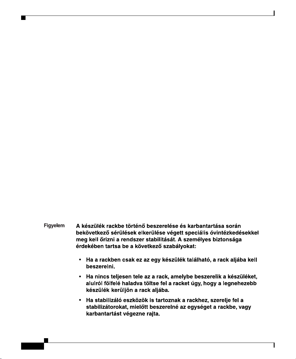
Statement 1006—Chassis Warning for Rack-Mounting and Servicing
Appendix C Translated Safety Warnings
¡Advertencia!
Varning!
Para evitar lesiones durante el montaje de este equipo sobre un bastidor, o
posteriormente durante su mantenimiento, se debe poner mucho cuidado en
que el sistema quede bien estable. Para garantizar su seguridad, proceda
según las siguientes instrucciones:
• Colocar el equipo en la parte inferior del bastidor, cuando sea la única unidad en el
mismo.
• Cuando este equipo se vaya a instalar en un bastidor parcialmente ocupado,
comenzar la instalación desde la parte inferior hacia la superior colocando el equipo
más pesado en la parte inferior.
• Si el bastidor dispone de dispositivos estabilizadores, instalar éstos antes de montar
o proceder al mantenimiento del equipo instalado en el bastidor.
För att undvika kroppsskada när du installerar eller utför underhållsarbete på
denna enhet på en ställning måste du vidta särskilda försiktighetsåtgärder för
att försäkra dig om att systemet står stadigt. Följande riktlinjer ges för att
trygga din säkerhet:
• Om denna enhet är den enda enheten på ställningen skall den installeras längst ned
på ställningen.
• Om denna enhet installeras på en delvis fylld ställning skall ställningen fyllas
nedifrån och upp, med de tyngsta enheterna längst ned på ställningen.
• Om ställningen är försedd med stabiliseringsdon skall dessa monteras fast innan
enheten installeras eller underhålls på ställningen.
C-18
Cisco RPS 675 Redundant Power System Hardware Installation Guide
78-15201-04
Page 77

Appendix C Translated Safety Warnings
•
•
•
•
•
•
Statement 1006—Chassis Warning for Rack-Mounting and Servicing
78-15201-04
•
•
•
Cisco RPS 675 Redundant Power System Hardware Installation Guide
C-19
Page 78

Statement 1006—Chassis Warning for Rack-Mounting and Servicing
Appendix C Translated Safety Warnings
Aviso
Advarsel
Para evitar lesões corporais ao montar ou dar manutenção a esta unidade em
um rack, é necessário tomar todas as precauções para garantir a estabilidade
do sistema. As seguintes orientações são fornecidas para garantir a sua
segurança:
• Se esta for a única unidade, ela deverá ser montada na parte inferior do rack.
• Ao montar esta unidade em um rack parcialmente preenchido, carregue-o de baixo
para cima com o componente mais pesado em sua parte inferior.
• Se o rack contiver dispositivos estabilizadores, instale-os antes de montar ou dar
manutenção à unidade existente.
For at forhindre legemesbeskadigelse ved montering eller service af denne
enhed i et rack, skal du sikre at systemet står stabilt. Følgende retningslinjer
er også for din sikkerheds skyld:
• Enheden skal monteres i bunden af dit rack, hvis det er den eneste enhed i racket.
• Ved montering af denne enhed i et delvist fyldt rack, skal enhederne installeres fra
bunden og opad med den tungeste enhed nederst.
• Hvis racket leveres med stabiliseringsenheder, skal disse installeres for enheden
monteres eller serviceres i racket.
C-20
Cisco RPS 675 Redundant Power System Hardware Installation Guide
78-15201-04
Page 79

Appendix C Translated Safety Warnings
Statement 1006—Chassis Warning for Rack-Mounting and Servicing
78-15201-04
Cisco RPS 675 Redundant Power System Hardware Installation Guide
C-21
Page 80

Statement 1006—Chassis Warning for Rack-Mounting and Servicing
Appendix C Translated Safety Warnings
C-22
Cisco RPS 675 Redundant Power System Hardware Installation Guide
78-15201-04
Page 81
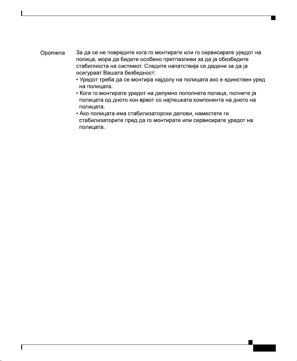
Appendix C Translated Safety Warnings
Statement 1006—Chassis Warning for Rack-Mounting and Servicing
78-15201-04
Cisco RPS 675 Redundant Power System Hardware Installation Guide
C-23
Page 82

Statement 1006—Chassis Warning for Rack-Mounting and Servicing
Appendix C Translated Safety Warnings
C-24
Cisco RPS 675 Redundant Power System Hardware Installation Guide
78-15201-04
Page 83

Appendix C Translated Safety Warnings
Statement 1017—Restricted Area
Statement 1017—Restricted Area
Warning
Waarschuwing
Varoitus
Attention
Warnung
Avvertenza
This unit is intended for installation in restricted access areas. A restricted
access area can be accessed only through the use of a special tool, lock and
key, or other means of security.
Deze eenheid is bestemd voor installatie in plaatsen met beperkte toegang.
Toegang tot een dergelijke plaats kan alleen verkregen worden door middel
van een speciaal instrument, een slot en sleutel of een ander
veiligheidsmiddel.
Tämä laite on tarkoitettu asennettavaksi paikkaan, johon pääsy on rajoitettua.
Tällaiseen paikkaan pääsee vain erikoistyökalua, lukkoon sopivaa avainta tai
jotakin muuta turvalaitetta käyttämällä.
Cet appareil est à installer dans des zones d'accès réservé. L'accès à une
zone d'accès réservé n'est possible qu'en utilisant un outil spécial, un
mécanisme de verrouillage et une clé, ou tout autre moyen de sécurité.
Diese Einheit ist zur Installation in Bereichen mit beschränktem Zutritt
vorgesehen. Der Zutritt zu derartigen Bereichen ist nur mit einem
Spezialwerkzeug, Schloss und Schlüssel oder einer sonstigen
Sicherheitsvorkehrung möglich.
Questa unità è prevista per essere installata in un'area ad accesso limitato,
vale a dire un'area accessibile solo mediante l'uso di un attrezzo speciale,
come lucchetto e chiave, o altri dispositivi di sicurezza.
Statement 1017
78-15201-04
Advarsel
Aviso
Denne enheten er beregnet på installasjon i områder med begrenset tilgang.
Et begrenset tilgangsområde kan bare nås ved hjelp av et spesielt verktøy, lås
og nøkkel, eller andre sikkerhetsanordninger.
Esta unidade foi concebida para instalação em áreas de acesso restrito. Uma
área de acesso restrito é uma área à qual apenas tem acesso o pessoal de
serviço autorizado, que possua uma ferramenta, chave e fechadura especial,
ou qualquer outra forma de segurança.
Cisco RPS 675 Redundant Power System Hardware Installation Guide
C-25
Page 84

Statement 1017—Restricted Area
Appendix C Translated Safety Warnings
¡Advertencia!
Varning!
Esta unidad ha sido diseñada para instalación en áreas de acceso restringido.
Sólo puede obtenerse acceso a una de estas áreas mediante la utilización de
una herramienta especial, cerradura con llave u otro medio de seguridad.
Denna enhet är avsedd för installation i områden med begränsat tillträde. Ett
område med begränsat tillträde kan endast tillträdas med hjälp av
specialverktyg, lås och nyckel eller annan säkerhetsanordning.
C-26
Aviso
Esta unidade deve ser instalada em áreas de acesso restrito. Uma área de
acesso restrito só pode ser acessada com o uso de uma ferramenta especial,
cadeado e chave ou outros meios de segurança.
Advarsel
Denne enhed er beregnet til installation i områder med begrænset adgang. Der
kan kun opnås adgang til et begrænset område ved at bruge et særligt stykke
værktøj, lås og nøgle, eller en anden form for sikkerhed.
Cisco RPS 675 Redundant Power System Hardware Installation Guide
78-15201-04
Page 85

Appendix C Translated Safety Warnings
Statement 1017—Restricted Area
78-15201-04
Cisco RPS 675 Redundant Power System Hardware Installation Guide
C-27
Page 86

Appendix C Translated Safety Warnings
Statement 1019—Main Disconnecting Device
Statement 1019—Main Disconnecting Device
Warning
Waarschuwing
Varoitus
Attention
Warnung
Avvertenza
C-28
The plug-socket combination must be accessible at all times, because it
serves as the main disconnecting device.
De combinatie van de stekker en het elektrisch contactpunt moet te allen tijde
toegankelijk zijn omdat deze het hoofdmechanisme vormt voor verbreking van
de aansluiting.
Pistoke/liitinkohta toimii pääkatkaisumekanismina. Pääsy siihen on pidettävä
aina esteettömänä.
La combinaison de prise de courant doit être accessible à tout moment parce
qu'elle fait office de système principal de déconnexion.
Der Netzkabelanschluß am Gerät muß jederzeit zugänglich sein, weil er als
primäre Ausschaltvorrichtung dient.
Il gruppo spina-presa deve essere sempre accessibile, poiché viene utilizzato
come dispositivo di scollegamento principale.
Cisco RPS 675 Redundant Power System Hardware Installation Guide
Statement 1019
78-15201-04
Page 87
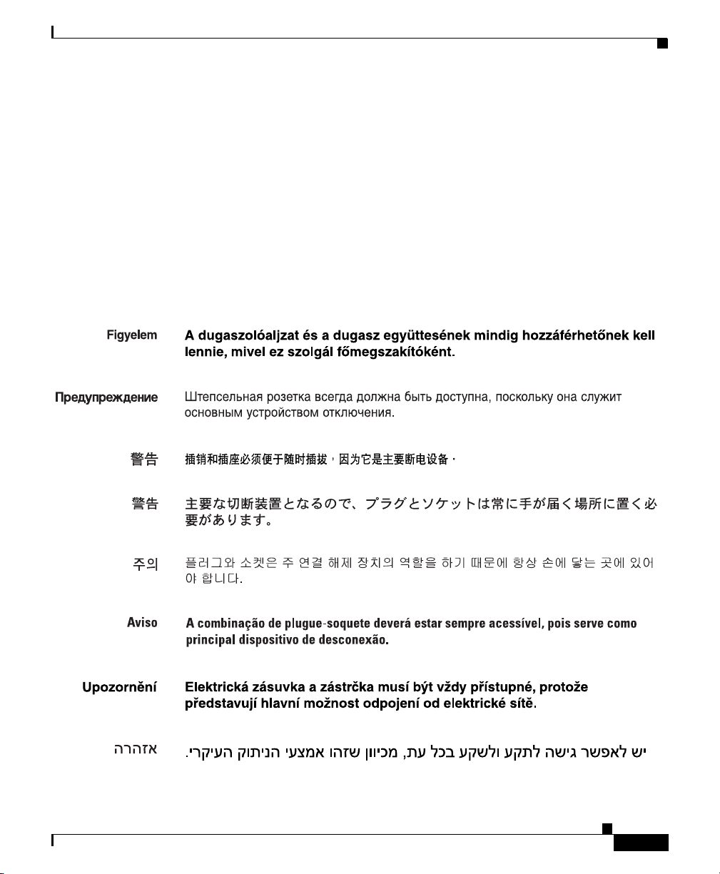
Appendix C Translated Safety Warnings
Statement 1019—Main Disconnecting Device
Advarsel
Aviso
¡Advertencia!
Varning!
Kombinasjonen støpsel/uttak må alltid være tilgjengelig ettersom den
fungerer som hovedfrakoplingsenhet.
A combinação ficha-tomada deverá ser sempre acessível, porque funciona
como interruptor principal.
El conjunto de clavija y toma ha de encontrarse siempre accesible ya que
hace las veces de dispositivo de desconexión principal.
Man måste alltid kunna komma åt stickproppen i uttaget, eftersom denna
koppling utgör den huvudsakliga frånkopplingsanordningen.
78-15201-04
Cisco RPS 675 Redundant Power System Hardware Installation Guide
C-29
Page 88

Appendix C Translated Safety Warnings
Statement 1024—Ground Conductor
Statement 1024—Ground Conductor
Warning
Waarschuwing
Varoitus
C-30
This equipment must be grounded. Never defeat the ground conductor or
operate the equipment in the absence of a suitably installed ground conductor.
Contact the appropriate electrical inspection authority or an electrician if you
are uncertain that suitable grounding is available.
Deze apparatuur dient geaard te zijn. De aardingsleiding mag nooit buiten
werking worden gesteld en de apparatuur mag nooit bediend worden zonder
dat er een op de juiste wijze geïnstalleerde aardingsleiding aanwezig is.
Neem contact op met de bevoegde instantie voor elektrische inspecties of met
een elektricien als u er niet zeker van bent dat er voor passende aarding
gezorgd
Laitteiden on oltava maadoitettuja. Älä koskaan ohita maajohdinta tai käytä
laitteita ilman oikein asennettua maajohdinta. Ota yhteys
sähkötarkastusviranomaiseen tai sähköasentajaan, jos olet epävarma
maadoituksen sopivuudesta.
Cisco RPS 675 Redundant Power System Hardware Installation Guide
is.
Statement 1024
78-15201-04
Page 89

Appendix C Translated Safety Warnings
Statement 1024—Ground Conductor
Attention
Warnung
Avvertenza
Advarsel
Aviso
Cet équipement doit être mis à la masse. Ne jamais rendre inopérant le
conducteur de masse ni utiliser l'équipement sans un conducteur de masse
adéquatement installé. En cas de doute sur la mise à la masse appropriée
disponible, s'adresser à l'organisme responsable de la sécurité électrique ou
à un électricien.
Dieses Gerät muss geerdet sein. Auf keinen Fall den Erdungsleiter unwirksam
machen oder das Gerät ohne einen sachgerecht installierten Erdungsleiter
verwenden. Wenn Sie sich nicht sicher sind, ob eine sachgerechte Erdung
vorhanden ist, wenden Sie sich an die zuständige Inspektionsbehörde oder
einen Elektriker.
Questa apparecchiatura deve essere dotata di messa a terra. Non escludere
mai il conduttore di protezione né usare l'apparecchiatura in assenza di un
conduttore di protezione installato in modo corretto. Se non si è certi della
disponibilità di un adeguato collegamento di messa a terra, richiedere un
controllo elettrico presso le autorità competenti o rivolgersi a un elettricista.
Dette utstyret må jordes. Omgå aldri jordingslederen og bruk aldri utstyret
uten riktig montert jordingsleder. Ta kontakt med fagfolk innen elektrisk
inspeksjon eller med en elektriker hvis du er usikker på om det finnes
velegnet jordning.
Este equipamento deve ser aterrado. Nunca anule o fio terra nem opere o
equipamento sem um aterramento adequadamente instalado. Em caso de
dúvida com relação ao sistema de aterramento disponível, entre em contato
com os serviços locais de inspeção elétrica ou um eletricista qualificado.
¡Advertencia!
78-15201-04
Varning!
Este equipo debe estar conectado a tierra. No inhabilite el conductor de tierra
ni haga funcionar el equipo si no hay un conductor de tierra instalado
correctamente. Póngase en contacto con la autoridad correspondiente de
inspección eléctrica o con un electricista si no está seguro de que haya una
conexión a tierra adecuada.
Denna utrustning måste jordas. Koppla aldrig från jordledningen och använd
aldrig utrustningen utan en på lämpligt sätt installerad jordledning. Om det
föreligger osäkerhet huruvida lämplig jordning finns skall elektrisk
besiktningsauktoritet eller elektriker kontaktas.
Cisco RPS 675 Redundant Power System Hardware Installation Guide
C-31
Page 90

Statement 1024—Ground Conductor
Appendix C Translated Safety Warnings
C-32
Cisco RPS 675 Redundant Power System Hardware Installation Guide
78-15201-04
Page 91

Appendix C Translated Safety Warnings
Statement 1024—Ground Conductor
78-15201-04
Cisco RPS 675 Redundant Power System Hardware Installation Guide
C-33
Page 92
Appendix C Translated Safety Warnings
Statement 1030—Equipment Installation
Statement 1030—Equipment Installation
Warning
Waarschuwing
Varoitus
Attention
Warnung
Avvertenza
Advarsel
Aviso
Only trained and qualified personnel should be allowed to install, replace, or
service this
Deze apparatuur mag alleen worden geïnstalleerd, vervangen of hersteld door
bevoegd geschoold
Tämän laitteen saa asentaa, vaihtaa tai huoltaa ainoastaan koulutettu ja
laitteen tunteva
Il est vivement recommandé de confier l'installation, le remplacement et la
maintenance de ces équipements à des personnels qualifiés et expérimentés.
Das Installieren, Ersetzen oder Bedienen dieser Ausrüstung sollte nur
geschultem, qualifiziertem Personal gestattet werden.
Questo apparato può essere installato, sostituito o mantenuto unicamente da
un personale competente.
Bare opplært og kvalifisert personell skal foreta installasjoner, utskiftninger
eller service på dette
Apenas pessoal treinado e qualificado deve ser autorizado a instalar,
substituir ou fazer a revisão deste equipamento.
equipment.
henkilökunta.
Statement 1030
personeel.
utstyret.
¡Advertencia!
C-34
Solamente el personal calificado debe instalar, reemplazar o utilizar este
equipo.
Varning!
Cisco RPS 675 Redundant Power System Hardware Installation Guide
Endast utbildad och kvalificerad personal bör få tillåtelse att installera, byta
ut eller reparera denna
utrustning.
78-15201-04
Page 93

Appendix C Translated Safety Warnings
Statement 1030—Equipment Installation
Aviso
Advarsel
Somente uma equipe treinada e qualificada tem permissão para instalar,
substituir ou dar manutenção a este equipamento.
Kun uddannede personer må installere, udskifte komponenter i eller servicere
dette udstyr.
78-15201-04
Cisco RPS 675 Redundant Power System Hardware Installation Guide
C-35
Page 94

Statement 1040—Product Disposal
Statement 1040—Product Disposal
Appendix C Translated Safety Warnings
Warning
Waarschuwing
Varoitus
Attention
Warnung
Avvertenza
Advarsel
C-36
Ultimate disposal of this product should be handled according to all national
laws and regulations.
Het uiteindelijke wegruimen van dit product dient te geschieden in
overeenstemming met alle nationale wetten en reglementen.
Tämä tuote on hävitettävä kansallisten lakien ja määräysten mukaisesti.
La mise au rebut ou le recyclage de ce produit sont généralement soumis à des
lois et/ou directives de respect de l'environnement. Renseignez-vous auprès
de l'organisme compétent.
Die Entsorgung dieses Produkts sollte gemäß allen Bestimmungen und
Gesetzen des Landes erfolgen.
Lo smaltimento di questo prodotto deve essere eseguito secondo le leggi e
regolazioni locali.
Endelig kassering av dette produktet skal være i henhold til alle relevante
nasjonale lover og bestemmelser.
Cisco RPS 675 Redundant Power System Hardware Installation Guide
Statement 1040
78-15201-04
Page 95

Appendix C Translated Safety Warnings
Statement 1040—Product Disposal
Aviso
¡Advertencia!
Varning!
Deitar fora este produto em conformidade com todas as leis e regulamentos
nacionais.
Al deshacerse por completo de este producto debe seguir todas las leyes y
reglamentos nacionales.
Vid deponering hanteras produkten enligt gällande lagar och bestämmelser.
78-15201-04
Aviso
Advarsel
O descarte definitivo deste produto deve estar de acordo com todas as leis e
regulamentações nacionais.
Endelig bortskaffelse af dette produkt skal ske i henhold til gældende love og
regler.
Cisco RPS 675 Redundant Power System Hardware Installation Guide
C-37
Page 96

Statement 1073—No User-Serviceable Parts
Appendix C Translated Safety Warnings
Statement 1073—No User-Serviceable Parts
Warning
Waarschuwing
Cisco RPS 675 Redundant Power System Hardware Installation Guide
C-38
No user-serviceable parts inside. Do not open.
Er zijn geen door de gebruiker te vervangen onderdelen. Niet openen.
Statement 1073
78-15201-04
Page 97

Appendix C Translated Safety Warnings
Statement 1073—No User-Serviceable Parts
Varoitus
Attention
Warnung
Avvertenza
Advarsel
Aviso
¡Advertencia!
Varning!
Ei sisällä käyttäjän huollettavissa olevia osia. Älä avaa.
Aucune pièce se trouvant à l'intérieur ne peut être réparée ou remplacée par
l'utilisateur. Ne pas ouvrir.
Enthält keine Teile, die vom Benutzer gewartet werden müssen. Bitte nicht
öffnen.
Non contiene parti riparabili dall'utente. Non aprire.
Inneholder ingen deler som kan repareres av brukeren. Må ikke åpnes.
Sem peças sujeitas a manutenção pelo utilizador. Não abrir.
No contiene partes que puedan ser arregladas por el usuario. No abrir.
Det finns inga delar som användare kan utföra service på. Öppna inte.
78-15201-04
Aviso
Advarsel
Manutenção somente por técnico especializado. Não abra.
Ingen dele indeni som brugere kan reparere. Åbn ej.
Cisco RPS 675 Redundant Power System Hardware Installation Guide
C-39
Page 98

Statement 1073—No User-Serviceable Parts
Appendix C Translated Safety Warnings
C-40
Cisco RPS 675 Redundant Power System Hardware Installation Guide
78-15201-04
Page 99

Appendix C Translated Safety Warnings
Statement 1074—Comply with Local and National Electrical Codes
Statement 1074—Comply with Local and National
Electrical Codes
Warning
Waarschuwing
Varoitus
Attention
Warnung
Avvertenza
Advarsel
Aviso
¡Advertencia!
Installation of the equipment must comply with local and national electrical
codes.
Bij installatie van de apparatuur moet worden voldaan aan de lokale en
nationale elektriciteitsvoorschriften.
Laitteisto tulee asentaa paikallisten ja kansallisten sähkömääräysten
mukaisesti.
L'équipement doit être installé conformément aux normes électriques
nationales et locales.
Die Installation der Geräte muss den Sicherheitsstandards entsprechen.
L'installazione dell'impianto deve essere conforme ai codici elettrici locali e
nazionali.
Installasjon av utstyret må samsvare med lokale og nasjonale
elektrisitetsforskrifter.
A instalação do equipamento tem de estar em conformidade com os códigos
eléctricos locais e nacionais.
La instalación del equipo debe cumplir con las normativas de electricidad
locales y nacionales.
Statement 1074
78-15201-04
Varning!
Installation av utrustningen måste ske i enlighet med gällande
elinstallationsföreskrifter.
Cisco RPS 675 Redundant Power System Hardware Installation Guide
C-41
Page 100

Statement 1074—Comply with Local and National Electrical Codes
Appendix C Translated Safety Warnings
C-42
Cisco RPS 675 Redundant Power System Hardware Installation Guide
78-15201-04
 Loading...