

Page 1
Page 2

Table of Contents
Cisco Switching Black Book...............................................................................................................................1
Introduction.........................................................................................................................................................4
Overview..................................................................................................................................................4
Is This Book for You?..............................................................................................................................4
How to Use This Book.............................................................................................................................4
The Black Book Philosophy....................................................................................................................5
Chapter 1: Network Switching Fundamentals.................................................................................................6
In Depth...................................................................................................................................................6
Physical Media and Switching Types......................................................................................................6
A Bit of History.......................................................................................................................................7
Networking Architectures.................................................................................................................7
The Pieces of Technology........................................................................................................................9
Repeaters.........................................................................................................................................10
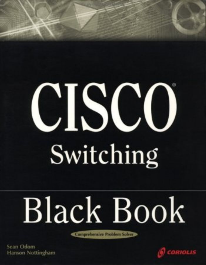
Hubs.................................................................................................................................................10
Bridges.............................................................................................................................................11
Routers.............................................................................................................................................13
Switches...........................................................................................................................................13
Network Design.....................................................................................................................................14
Collision Domains...........................................................................................................................15
Broadcast Domains..........................................................................................................................16
Why Upgrade to Switches?.............................................................................................................16
Switched Forwarding......................................................................................................................19
Switched Network Bottlenecks.......................................................................................................20
The Rule of the Network Road........................................................................................................22
Switched Ethernet Innovations..............................................................................................................23
Full−Duplex Ethernet......................................................................................................................23
Fast Ethernet....................................................................................................................................23
Gigabit Ethernet..............................................................................................................................24
The Cisco IOS........................................................................................................................................24
Connecting to the Switch................................................................................................................25
Powering Up the Switch..................................................................................................................25
The Challenges.......................................................................................................................................27
Today’s Trend........................................................................................................................................27
Entering and Exiting Privileged EXEC Mode.......................................................................................28
Entering and Exiting Global Configuration Mode.................................................................................28
Entering and Exiting Interface Configuration Mode.............................................................................28
Entering and Exiting Subinterface Configuration Mode.......................................................................28
Saving Configuration Changes..............................................................................................................29
Chapter 2: Basic Switch Configuration..........................................................................................................30
In Depth.................................................................................................................................................30
Command−Line Interfaces....................................................................................................................30
Campus Hierarchical Switching Model.................................................................................................31
Access Layer...................................................................................................................................32
Distribution Layer...........................................................................................................................32
Core Layer.......................................................................................................................................33
Remote Network Monitoring.................................................................................................................33
Connecting to the Console Port.............................................................................................................34
Console Cable Pinouts.....................................................................................................................35
Console Connectors.........................................................................................................................36
i
Page 3

Table of Contents
Chapter 2: Basic Switch Configuration
The RJ−45−to−AUX Port Console Connector Pinouts...................................................................36
Switch IOSs...........................................................................................................................................38
The IOS Configuration Modes........................................................................................................38
Limiting Telnet Access..........................................................................................................................39
Implementing Privilege Levels..............................................................................................................39
Configuring an IOS−Based CLI Switch................................................................................................39
Setting the Login Passwords...........................................................................................................40
Setting Privilege Levels...................................................................................................................40
Assigning Allowable Commands....................................................................................................40
Setting the Console Port Time−out Value.......................................................................................40
Configuring the Telnet Time−out Value.........................................................................................41
Configuring the Hostname..............................................................................................................41
Configuring the Date and Time.......................................................................................................41
Configuring an IP Address and Netmask........................................................................................41
Configuring a Default Route and Gateway.....................................................................................41
Configuring Port Speed and Duplex...............................................................................................42
Enabling SNMP Contact.................................................................................................................42
Configuring a Set/Clear−Based CLI Switch..........................................................................................42
Logging On to a Switch...................................................................................................................42
Setting the Login and Enable Passwords........................................................................................43
Changing the Console Prompt.........................................................................................................43
Entering a Contact Name and Location Information......................................................................44
Configuring System and Time Information....................................................................................44
Configuring an IP Address and Netmask........................................................................................44
Configuring a Default Route and Gateway.....................................................................................45
Viewing the Default Routes............................................................................................................45
Configuring Port Speed and Duplex...............................................................................................45
Enabling SNMP...............................................................................................................................46
Configuring Trap Message Targets.................................................................................................46
Configuring a Menu−Driven IOS..........................................................................................................47
Configuring the Console Port..........................................................................................................48
Configuring Telnet..........................................................................................................................48
Configuring the Password...............................................................................................................48
Configuring an IP Address and Default Gateway...........................................................................48
Configuring SNMP..........................................................................................................................49
Configuring ROM..................................................................................................................................50
Entering ROM Configuration Mode...............................................................................................50
Booting ROM Mode from a Flash Device......................................................................................50
Configuring SNMP..........................................................................................................................51
Configuring RMON........................................................................................................................51
Configuring RMON on a Set/Clear−Based Interface.....................................................................51
Using Set/Clear Command Set Recall Key Sequences..........................................................................52
Using IOS−Based Command Editing Keys and Functions...................................................................52
Chapter 3: WAN Switching.............................................................................................................................54
In Depth.................................................................................................................................................54
WAN Transmission Media....................................................................................................................55
Synchronous Transport Signal (STS)..............................................................................................56
Cisco WAN Switches............................................................................................................................57
MGX 8200 Series............................................................................................................................57
IGX 8400 Series..............................................................................................................................58
ii
Page 4

Chapter 3: WAN Switching
BPX 8600 Series Wide−Area Switches..........................................................................................58
MGX 8800 Series Wide−Area Edge Switches...............................................................................59
WAN Switch Hardware Overview........................................................................................................59
Cisco WAN Switch Network Topologies..............................................................................................60
Network Management............................................................................................................................61
The CLI...........................................................................................................................................61
WAN Manager................................................................................................................................61
Accessing and Setting Up IGX and BPX Switches...............................................................................62
Adding New Users..........................................................................................................................62
Displaying a User’s Password.........................................................................................................62
Changing a User’s Password...........................................................................................................62
Using the History Command...........................................................................................................63
Displaying a Summary of All Card Modules..................................................................................63
Displaying Detailed Information for a Card Module......................................................................63
Displaying the Power and Temperature of a Switch.......................................................................63
Displaying the ASM Statistics for BPX..........................................................................................63
Configuring the ASM Setting for BPX...........................................................................................63
Logging Out....................................................................................................................................63
Resetting the Switch........................................................................................................................63
Displaying Other Switches..............................................................................................................64
Setting the Switch Name.................................................................................................................64
Setting the Time Zone.....................................................................................................................64
Configuring the Time and Date.......................................................................................................64
Configuring the Control and Auxiliary Ports..................................................................................64
Modifying the Functions of the Control and Auxiliary Ports.........................................................64
Configuring the Printing Function..................................................................................................64
Configuring the LAN Interface.......................................................................................................64
Accessing the MGX 8850 and 8220......................................................................................................65
Adding New Users..........................................................................................................................65
Changing Passwords........................................................................................................................65
Assigning a Switch Hostname.........................................................................................................65
Displaying a Summary of All Modules...........................................................................................66
Displaying Detailed Information for the Current Card...................................................................66
Changing the Time and Date...........................................................................................................66
Displaying the Configuration of the Maintenance and Control Ports.............................................66
Displaying the IP Address...............................................................................................................66
Configuring the IP Interface............................................................................................................67
Displaying the Alarm Level of the Switch......................................................................................67
Table of Contents
Chapter 4: LAN Switch Architectures............................................................................................................68
In Depth.................................................................................................................................................68
The Catalyst Crescendo Architecture....................................................................................................68
BUS.................................................................................................................................................68
ASICs..............................................................................................................................................69
The Crescendo Processors...............................................................................................................71
Crescendo Logic Units....................................................................................................................71
Other Cisco Switch Processors, Buses, ASICs, and Logic Units..........................................................72
CAM................................................................................................................................................72
AXIS Bus........................................................................................................................................72
CEF ASIC........................................................................................................................................73
Phoenix ASIC..................................................................................................................................75
iii
Page 5

Table of Contents
Chapter 4: LAN Switch Architectures
LCP..................................................................................................................................................75
SAGE ASIC....................................................................................................................................75
QTP ASIC.......................................................................................................................................75
QMAC.............................................................................................................................................76
Bridging Types......................................................................................................................................76
Source Route Bridging....................................................................................................................76
Source Route Transparent Bridging................................................................................................77
Source Route Translational Bridging..............................................................................................77
Transparent Bridging.......................................................................................................................77
Source Route Switching..................................................................................................................77
Switching Paths......................................................................................................................................78
Process Switching............................................................................................................................78
Fast Switching.................................................................................................................................78
Autonomous Switching...................................................................................................................79
Silicon Switching............................................................................................................................79
Optimum Switching........................................................................................................................79
Distributed Switching......................................................................................................................79
NetFlow Switching..........................................................................................................................79
System Message Logging......................................................................................................................80
Loading an Image on the Supervisor Engine III....................................................................................80
Booting the Supervisor Engine III from Flash.......................................................................................81
Setting the Boot Configuration Register................................................................................................81
Configuring Cisco Express Forwarding.................................................................................................81
Enabling CEF..................................................................................................................................81
Disabling CEF.................................................................................................................................81
Enabling dCEF................................................................................................................................82
Disabling dCEF...............................................................................................................................82
Disabling CEF on an Individual Interface.......................................................................................82
Configuring CEF Load Balancing...................................................................................................82
Disabling CEF Load Balancing.......................................................................................................82
Enabling Network Accounting for CEF..........................................................................................82
Setting Network Accounting for CEF to Collect Packet Numbers.................................................82
Viewing Network Accounting for CEF Statistics...........................................................................82
Viewing CEF Packet−Dropped Statistics.......................................................................................83
Viewing Non−CEF Path Packets....................................................................................................83
Disabling Per−Destination Load Sharing..............................................................................................83
Viewing the Adjacency Table on the 8500 GSR...................................................................................83
Clearing the Adjacency Table on the 8500 GSR...................................................................................83
Enabling Console Session Logging on a Set/Clear Command−Based IOS..........................................83
Enabling Telnet Session Logging on a Set/Clear Command−Based IOS.............................................84
Disabling Console Session Logging on a Set/Clear Command−Based IOS.........................................84
Disabling Telnet Session Logging on a Set/Clear Command−Based IOS............................................84
Setting the System Message Severity Levels on a Set/Clear Command−Based IOS............................84
Enabling the Logging Time Stamp on a Set/Clear Command−Based Switch......................................84
Disabling the Logging Time Stamp on a Set/Clear Command−Based Switch.....................................85
Configuring the Logging Buffer Size on a Set/Clear Command−Based Switch...................................85
Clearing the Server Logging Table........................................................................................................85
Disabling Server Logging......................................................................................................................85
Displaying the Logging Configuration..................................................................................................86
Displaying System Logging Messages..................................................................................................86
iv
Page 6

Table of Contents
Chapter 5: Virtual Local Area Networks.......................................................................................................88
In Depth.................................................................................................................................................88
The Flat Network of Yesterday..............................................................................................................88
Why Use VLANs?.................................................................................................................................89
VLAN Basics..................................................................................................................................90
A Properly Switched Network........................................................................................................90
Switched Internetwork Security......................................................................................................91
Scaling with VLANs..............................................................................................................................92
VLAN Boundaries...........................................................................................................................92
VLAN Membership Types..............................................................................................................93
Traffic Patterns Flowing through the Network...............................................................................93
Cisco’s VLAN Recommendations..................................................................................................93
VLAN Trunking.....................................................................................................................................94
Trunk Types....................................................................................................................................94
LAN Emulation (LANE).................................................................................................................97
VLAN Trunking Protocol (VTP)...........................................................................................................97
VTP Versions..................................................................................................................................98
VTP Advertisements.......................................................................................................................98
VTP Switch Modes.......................................................................................................................100
Methods for VLAN Identification.................................................................................................101
Dynamic Trunking Protocol..........................................................................................................101
InterVLAN Routing.............................................................................................................................101
Internal Route Processors..............................................................................................................102
How InterVLAN Routing Works..................................................................................................102
Configuring a Static VLAN on a Catalyst 5000 Series Switch...........................................................103
Configuring Multiple VLANs on a Catalyst 5000 Series Switch........................................................103
Creating VLANs on a Catalyst 1900EN Series...................................................................................103
Assigning a Static VLAN to an Interface on a 1900EN Series...........................................................104
Viewing the VLAN Configuration on a 1900 Series...........................................................................105
Viewing an Individual VLAN Configuration on a 1900 Series..........................................................105
Configuring a Trunk Port on a Cisco 5000 Series...............................................................................105
Mapping VLANs to a Trunk Port........................................................................................................107
Configuring a Trunk Port on a Cisco 1900EN Series..........................................................................107
Clearing VLANs from Trunk Links on a Cisco 5000 Series...............................................................107
Clearing VLANs from Trunk Links on a Cisco 1900EN Series.........................................................107
Verifying a Trunk Link Configuration on a 5000 Series.....................................................................108
Verifying a Trunk Link Configuration on a 1900EN Series................................................................108
Configuring the VTP Version on a Catalyst 5000 Switch...................................................................108
Configuring a VTP Domain on a Catalyst 1900 Switch......................................................................109
Setting a VTP Domain Password on a Catalyst Switch.......................................................................109
Configuring a Catalyst 1900 Switch as a VTP Server.........................................................................109
Configuring a Catalyst 1900 Switch as a VTP Client.........................................................................109
Configuring a Catalyst 1900 Switch for Transparent Mode................................................................109
Configuring VTP Pruning on a Catalyst 1900 Switch.........................................................................110
Configuring VTP on a Set/Clear CLI Switch......................................................................................110
Configuring VTP on a 1900 Cisco IOS CLI Switch...........................................................................110
Verifying the VTP Configuration on a Set/Clear CLI.........................................................................111
Displaying VTP Statistics....................................................................................................................111
Configuring VTP Pruning on a Set/Clear CLI Switch........................................................................112
Disabling Pruning for Unwanted VLANs............................................................................................112
Configuring IP InterVLAN Routing on an External Cisco Router......................................................112
Configuring IPX InterVLAN Routing on an External Router.............................................................113
v
Page 7

Table of Contents
Chapter 6: InterVLAN and Basic Module Configuration..........................................................................114
In Depth...............................................................................................................................................114
Internal Route Processors....................................................................................................................114
Available Route Processors...........................................................................................................116
Routing Protocol Assignment.......................................................................................................120
Supervisor Engine Modules.................................................................................................................120
Supervisor Engines I and II...........................................................................................................120
Supervisor Engine III....................................................................................................................121
Using the Supervisor Engine.........................................................................................................122
Etherport Modules...............................................................................................................................122
Port Security..................................................................................................................................123
Manually Configured MAC Addresses.........................................................................................123
Determining the Slot Number in Which a Module Resides................................................................123
Accessing the Internal Route Processor from the Switch....................................................................124
Configuring a Hostname on the RSM..................................................................................................124
Assigning an IP Address and Encapsulation Type to an Ethernet Interface........................................125
Setting the Port Speed and Port Name on an Ethernet Interface.........................................................125
Configuring a Default Gateway on a Catalyst 5000............................................................................126
Verifying the IP Configuration on a Catalyst 5000.............................................................................126
Enabling RIP on an RSM.....................................................................................................................126
Viewing the RSM’s Running Configuration.......................................................................................127
Configuring InterVLAN Routing on an RSM.....................................................................................127
Configuring IPX InterVLAN Routing on the RSM.............................................................................128
Configuring AppleTalk InterVLAN Routing on an RSM...................................................................128
Viewing the RSM Configuration.........................................................................................................129
Assigning a MAC Address to a VLAN...............................................................................................129
Viewing the MAC Addresses..............................................................................................................129
Configuring Filtering on an Ethernet Interface....................................................................................130
Configuring Port Security on an Ethernet Module..............................................................................130
Clearing MAC Addresses....................................................................................................................131
Configuring the Catalyst 5000 Supervisor Engine Module.................................................................131
Setting the boot config−register on the Supervisor Engine Module....................................................132
Changing the Management VLAN on a Supervisor Engine................................................................133
Viewing the Supervisor Engine Configuration....................................................................................133
Configuring the Cisco 2621 External Router for ISL Trunking..........................................................134
Configuring Redundancy Using HSRP...............................................................................................135
Chapter 7: IP Multicast..................................................................................................................................137
In Depth...............................................................................................................................................137
IP Multicasting Overview....................................................................................................................137
Broadcast.......................................................................................................................................138
Unicast...........................................................................................................................................138
Multicast........................................................................................................................................139
IP Multicasting Addresses...................................................................................................................140
The Multicast IP Structure............................................................................................................140
Delivery of Multicast Datagrams..................................................................................................142
Multicast Distribution Tree...........................................................................................................142
Multicast Forwarding....................................................................................................................143
IGMP Protocols.............................................................................................................................143
Internet Group Management Protocol (IGMP)....................................................................................145
IGMPv1.........................................................................................................................................145
IGMPv2.........................................................................................................................................146
vi
Page 8

Chapter 7: IP Multicast
Time to Live..................................................................................................................................147
Multicast at Layer 2.............................................................................................................................147
IGMP Snooping.............................................................................................................................147
Cisco Group Management Protocol..............................................................................................148
Router Group Management Protocol............................................................................................148
GARP Multicast Registration Protocol.........................................................................................149
Configuring IP Multicast Routing.......................................................................................................149
Disabling IP Multicast Routing.....................................................................................................149
Enabling PIM on an Interface.......................................................................................................149
Disabling PIM on an Interface......................................................................................................149
Configuring the Rendezvous Point................................................................................................150
Adding a Router to a Multicast Group.................................................................................................150
Configuring a Router to Be a Static Multicast Group Member....................................................150
Restricting Access to a Multicast Group.......................................................................................150
Changing the IGMP Version...............................................................................................................150
Changing the IGMP Host−Query Message Interval............................................................................151
Configuring Multicast Groups.............................................................................................................151
Removing Multicast Groups................................................................................................................151
Configuring Multicast Router Ports.....................................................................................................151
Displaying Multicast Routers........................................................................................................151
Removing the Multicast Router....................................................................................................152
Configuring IGMP Snooping...............................................................................................................152
Disabling IGMP Snooping............................................................................................................152
Configuring IGMP Fast−Leave Processing.........................................................................................152
Disabling IGMP Fast−Leave Processing......................................................................................152
Displaying IGMP Statistics.................................................................................................................153
Displaying Multicast Routers Learned from IGMP.............................................................................153
Displaying IGMP Multicast Groups....................................................................................................153
Configuring CGMP..............................................................................................................................154
Disabling CGMP...........................................................................................................................154
Enabling CGMP Fast−Leave Processing......................................................................................154
Disabling CGMP Fast−Leave Processing.....................................................................................154
Displaying CGMP Statistics..........................................................................................................154
Configuring RGMP on the Switch.......................................................................................................155
Disabling RGMP on the Switch....................................................................................................155
Configuring RGMP on the Router.......................................................................................................155
Disabling RGMP on the Router....................................................................................................155
Displaying RGMP Groups...................................................................................................................155
Displaying RGMP−Capable Router Ports...........................................................................................156
Displaying RGMP VLAN Statistics....................................................................................................156
Configuring GMRP..............................................................................................................................156
Disabling GMRP...........................................................................................................................157
Enabling GMRP on Individual Ports.............................................................................................157
Disabling GMRP on Individual Ports...........................................................................................157
Enabling GMRP Forward−All......................................................................................................157
Disabling GMRP Forward−All.....................................................................................................157
Configuring GMRP Registration...................................................................................................157
Displaying the GMRP Configuration............................................................................................158
Setting GMRP Timers...................................................................................................................158
Displaying GMRP Timers.............................................................................................................158
Configuring Bandwidth−Based Suppression.......................................................................................159
Table of Contents
vii
Page 9

Table of Contents
Chapter 7: IP Multicast
Configuring Packet−Based Suppression..............................................................................................159
Disabling Multicast Suppression.........................................................................................................159
Chapter 8: WAN Cell Switching...................................................................................................................160
In Depth...............................................................................................................................................160
ATM Overview....................................................................................................................................160
LANE............................................................................................................................................161
ATM Protocols..............................................................................................................................162
ATM Circuit Switching.................................................................................................................162
ATM Cells.....................................................................................................................................162
The ATM Switch and ATM Endpoints.........................................................................................164
The ATM Reference Model..........................................................................................................164
Specifying ATM Connections.......................................................................................................166
ATM Addressing...........................................................................................................................167
Local Area Network Emulation (LANE).............................................................................................167
LANE Components.......................................................................................................................168
Integrated Local Management Interface (ILMI)...........................................................................172
LANE Communication..................................................................................................................172
LANE Configuration Guidelines...................................................................................................174
How LANE Works........................................................................................................................174
Implementing LANE.....................................................................................................................175
Configuring ATM on the 5000 Switch..........................................................................................175
Connecting in an ATM Network...................................................................................................177
Monitoring and Maintaining LANE....................................................................................................178
Accessing the ATM LANE Module....................................................................................................178
Displaying the Selector Field...............................................................................................................178
Configuring the LES/BUS...................................................................................................................179
Verifying the LES/BUS Configuration.........................................................................................179
Configuring a LEC for an ELAN.........................................................................................................179
Verifying a LEC Configuration on an ELAN...............................................................................180
Configuring the LECS...................................................................................................................181
Viewing the LANE Database........................................................................................................181
Binding the LECS Address to an Interface...................................................................................181
Verifying the LECS Configuration...............................................................................................182
Chapter 9: LightStream Switches.................................................................................................................183
In Depth...............................................................................................................................................183
LightStream 100..................................................................................................................................183
LightStream 1010................................................................................................................................184
LightStream 2020................................................................................................................................185
Neighborhood Discovery Function...............................................................................................186
Virtual Path Connections.....................................................................................................................186
LightStream Troubleshooting Tools....................................................................................................187
LightStream Boot Process.............................................................................................................187
Supported Troubleshooting Protocols...........................................................................................188
Snooping Mechanisms..................................................................................................................188
Multiprotocol Over ATM..............................................................................................................188
Configuring the Hostname...................................................................................................................189
Configuring an Enable Password.........................................................................................................189
Configuring the Processor Card Ethernet Interface.............................................................................189
Configuring Virtual Private Tunnels...................................................................................................190
viii
Page 10

Table of Contents
Chapter 9: LightStream Switches
Verifying an ATM Interface Connection Status..................................................................................190
Viewing the Configured Virtual Connections.....................................................................................191
Configuring the LECS ATM Address on a LightStream 1010 Switch...............................................191
Configuring the Advertised LECS Address.........................................................................................191
Viewing the LANE Configuration.......................................................................................................191
Viewing the Installed Modules............................................................................................................192
Configuring the MPC...........................................................................................................................193
Configuring the MPS...........................................................................................................................193
Changing the MPS Variables........................................................................................................193
Monitoring the MPS......................................................................................................................194
Enabling ILMI Autoconfiguration.......................................................................................................194
Configuring LANE on a LightStream 1010.........................................................................................194
Powering on the LightStream 100 ATM Switch.................................................................................195
Configuring the LS100 Switch............................................................................................................195
Recovering a Lost Password................................................................................................................196
Chapter 10: Layer 2 Redundant Links.........................................................................................................199
In Depth...............................................................................................................................................199
Layer 2 Switching Overview...............................................................................................................199
Frames..................................................................................................................................................199
Broadcast and Multicast Frames...................................................................................................200
Unknown Unicasts........................................................................................................................200
Layer 2 Network Loops.......................................................................................................................200
Danger! Data Loops!.....................................................................................................................201
Edsger Dijkstra’s Graph Theory....................................................................................................201
STP Root Bridges..........................................................................................................................202
Bridge Protocol Data Units...........................................................................................................203
Root Bridge Selection...................................................................................................................205
Spanning Tree Convergence Time................................................................................................207
STP Port States..............................................................................................................................208
Per−VLAN Spanning Tree............................................................................................................209
EtherChannel........................................................................................................................................209
Link Failure...................................................................................................................................210
Port Aggregation Protocol.............................................................................................................210
Fast Convergence Components of STP...............................................................................................211
PortFast..........................................................................................................................................211
UplinkFast.....................................................................................................................................211
BackboneFast................................................................................................................................212
Enabling STP on a Set/Clear Command−Based Switch......................................................................212
Enabling STP on a Set/Clear Command−Based Switch for All VLANs............................................213
Disabling STP on a Set/Clear Command−Based Switch.....................................................................213
Disabling STP on a Set/Clear Command−Based Switch by VLAN...................................................213
Viewing the STP Configuration on a Set/Clear Command−Based Switch.........................................213
Configuring STP on an IOS Command−Based Switch.......................................................................214
Disabling STP on an IOS Command−Based Switch...........................................................................214
Viewing the STP Configuration on a Command Line Switch.............................................................215
Configuring the STP Root Switch.......................................................................................................215
Configuring the STP Secondary Root Switch.....................................................................................215
Setting the Root Bridge for More than One VLAN on a Set/Clear Command−Based Switch...........216
Assigning a Port Cost to a Port Using the Set/Clear Command−Based IOS......................................216
Assigning a Port Cost to a Port Using a CLI−Based Switch...............................................................216
ix
Page 11

Table of Contents
Chapter 10: Layer 2 Redundant Links
Verifying the Port Cost Configuration on Both a Set/Clear Command− and CLI−Based Interface...217
Configuring the Port Priority on a Set/Clear Command−Based IOS..................................................217
Configuring the Port Priority on a CLI−Based IOS............................................................................217
Verifying the STP Port Priority on a Set/Clear Command−Based Switch..........................................218
Verifying the VLAN Priority Settings.................................................................................................218
Adjusting the FwdDelay Timer on a Set/Clear Command−Based IOS...............................................218
Adjusting the Hello Timer on a Set/Clear Command−Based IOS......................................................218
Adjusting the MaxAge Timer on a Set/Clear Command−Based IOS.................................................219
Preparing to Enable EtherChannel.......................................................................................................219
Viewing the Port Setting for EtherChannel on a Set/Clear Command−Based Switch........................219
Creating an EtherChannel on a Set/Clear Command−Based Switch..................................................220
Verifying the EtherChannel Configuration..........................................................................................221
Defining an EtherChannel Administrative Group...............................................................................221
Viewing an EtherChannel Administrative Group................................................................................221
Configuring EtherChannel on an IOS−Based Switch..........................................................................222
Identifying the Template Port..............................................................................................................222
Verifying the EtherChannel Configuration on a Command Line Interface IOS.................................222
Enabling PortFast on a Set/Clear Command−Based Switch...............................................................223
Disabling PortFast on a Set/Clear Command−Based Switch..............................................................223
Enabling PortFast on a CLI−Based IOS Switch..................................................................................223
Disabling PortFast on a CLI−Based IOS Switch.................................................................................224
Verifying the PortFast Configuration..................................................................................................224
Enabling UplinkFast on a Set/Clear Command−Based Switch...........................................................224
Disabling UplinkFast on a Set/Clear Command−Based Switch..........................................................224
Verifying the UplinkFast Configuration..............................................................................................225
Enabling UplinkFast on a Cisco IOS Command−Based Switch.........................................................225
Disabling UplinkFast on a Cisco IOS Command−Based Switch........................................................225
Viewing the UplinkFast Configuration on an IOS−Based Switch......................................................226
Viewing UplinkFast Statistics on an IOS−Based Switch....................................................................226
Enabling BackboneFast on a Set/Clear Command−Based Switch......................................................226
Disabling BackboneFast on a Set/Clear Command−Based Switch.....................................................226
Viewing the BackboneFast Configuration...........................................................................................226
Chapter 11: Multilayer Switching.................................................................................................................227
In Depth...............................................................................................................................................227
How MLS Works.................................................................................................................................227
MLS Components..........................................................................................................................228
MLS Flows....................................................................................................................................230
Access List Flow Masks................................................................................................................231
MLS Troubleshooting Notes...............................................................................................................232
Configuring MLS.................................................................................................................................233
MLS Cache....................................................................................................................................234
Aging Timers.................................................................................................................................234
VLAN ID.......................................................................................................................................235
VTP Domain..................................................................................................................................235
Management Interfaces.................................................................................................................235
Configuring an External MLS Route Processor..................................................................................235
Enabling MLSP on an MLS−RP for IP.........................................................................................236
Disabling MLSP on an MLS−RP for IP........................................................................................236
Enabling MLSP on an MLS−RP for IPX......................................................................................236
Disabling MLSP on an MLS−RP for IPX.....................................................................................236
x
Page 12

Chapter 11: Multilayer Switching
Assigning a VLAN ID...................................................................................................................236
Adding an MLS Interface to a VTP Domain................................................................................236
Enabling MLS on an Individual Interface.....................................................................................237
Disabling MLS on an External Router Interface...........................................................................237
Configuring the MLS Switch Engine..................................................................................................237
Re−enabling MLS on a Catalyst 6000..........................................................................................237
Re−enabling MLS on a Catalyst 5000..........................................................................................238
Disabling MLS on a Catalyst 6000...............................................................................................238
Disabling MLS on a Catalyst 5000...............................................................................................238
Configuring the MLS Cache on the Catalyst 5000.......................................................................238
Configuring Fast Aging on a Catalyst 5000..................................................................................238
Configuring Fast Aging on a Catalyst 6000..................................................................................238
Disabling Fast Aging on a Catalyst 6000......................................................................................238
Configuring Long Aging on the Catalyst 6000.............................................................................239
Disabling Long Aging on the Catalyst 6000.................................................................................239
Configuring Normal Aging on the Catalyst 6000.........................................................................239
Disabling Normal Aging on the Catalyst 6000.............................................................................239
Assigning MLS Management to an Interface on the Catalyst 5000..............................................239
Disabling MLS Management on an Interface on the Catalyst 5000.............................................239
Monitoring and Viewing the MLS Configuration...............................................................................240
Viewing the MLS Aging Configuration on a Catalyst 6000.........................................................240
Displaying the IP MLS Configuration..........................................................................................240
Viewing MLS−RPs.......................................................................................................................240
Viewing MLS−RP Specifics.........................................................................................................240
Displaying MLS VTP Domain Information..................................................................................241
Viewing the MLS VLAN Interface Information...........................................................................241
Viewing MLS Statistics on the Catalyst 5000...............................................................................241
Viewing MLS Statistics on the Catalyst 6000...............................................................................242
Viewing MLS Entries....................................................................................................................242
Table of Contents
Chapter 12: Hot Standby Routing Protocol.................................................................................................243
In Depth...............................................................................................................................................243
Routing Problems................................................................................................................................243
Routing Information Protocol.......................................................................................................244
Proxy ARP.....................................................................................................................................244
ICMP Router Discovery Protocol.................................................................................................244
The Solution.........................................................................................................................................245
HSRP Message Format.................................................................................................................247
The HSRP States...........................................................................................................................247
HSRP Configuration............................................................................................................................248
HSRP Interface Tracking.....................................................................................................................248
Opening a Session on an Internal Route Processor.............................................................................249
Entering Configuration Mode on an RSM...........................................................................................249
Enabling HSRP and Assigning an IP Address to a Standby Group....................................................249
Assigning an HSRP Interface Priority.................................................................................................250
Assigning a Preempt Delay to a Standby Group.................................................................................250
Removing a Preempt Delay from a Standby Group............................................................................250
Setting the HSRP Hello and Hold Timers...........................................................................................250
Removing the HSRP Hello and Hold Timers......................................................................................251
Configuring a Clear−Text Password for HSRP Authentication..........................................................251
Configuring Two RSFC Interfaces as One HSRP Group....................................................................251
xi
Page 13

Table of Contents
Chapter 12: Hot Standby Routing Protocol
Enabling Interface Tracking................................................................................................................252
Using the show standby Command.....................................................................................................252
Using the debug Command..................................................................................................................253
Chapter 13: Policy Networking.....................................................................................................................254
In Depth...............................................................................................................................................254
Access Security Policies......................................................................................................................254
Core Layer Policies.......................................................................................................................255
Distribution Layer Policies............................................................................................................255
Security at the Access Layer................................................................................................................261
Configuring Passwords..................................................................................................................261
Limiting Telnet Access.................................................................................................................261
Implementing Privilege Levels.....................................................................................................261
Configuring Banner Messages......................................................................................................262
Physical Device Security...............................................................................................................262
Port Security..................................................................................................................................262
VLAN Management......................................................................................................................263
Creating a Standard Access List..........................................................................................................263
Creating an Extended Access List.......................................................................................................264
Applying Access Lists Using access−class.........................................................................................266
Applying Access Lists Using distribute−list.......................................................................................266
Configuring a Telnet Session Time−Out Value..................................................................................267
Implementing Privilege Levels on a 1900EN......................................................................................267
Configuring Line Console Time−Out Values......................................................................................267
Configuring Banner Messages.............................................................................................................268
Enabling HTTP Access........................................................................................................................268
Enabling Port Security.........................................................................................................................269
Displaying the MAC Address Table....................................................................................................270
Chapter 14: Web Management......................................................................................................................272
In Depth...............................................................................................................................................272
Standard and Enterprise Edition CVSM..............................................................................................272
CVSM Client Requirements................................................................................................................272
CVSM Access Levels..........................................................................................................................273
CVSM Default Home Page..................................................................................................................273
The Switch Image..........................................................................................................................274
Configuring the Switch with an IP Address and Setting the Default Web Administration Port.........275
Connecting to the Web Management Console.....................................................................................276
Configuring the Switch Port Analyzer.................................................................................................281
Chapter 15: The Standard Edition IOS........................................................................................................283
In Depth...............................................................................................................................................283
The 1900 and 2820 Series Switches....................................................................................................283
Main Menu Choices......................................................................................................................283
[C] Console Settings......................................................................................................................284
[S] System Menu...........................................................................................................................285
[N] Network Management.............................................................................................................286
[P] Port Configuration...................................................................................................................289
[A] Port Addressing.......................................................................................................................292
[D] Port Statistics Detail................................................................................................................293
[M] Monitor...................................................................................................................................293
xii
Page 14

Table of Contents
Chapter 15: The Standard Edition IOS
[V] Virtual LAN............................................................................................................................293
[R] Multicast Registration.............................................................................................................294
[F] Firmware..................................................................................................................................294
[I] RS−232 Interface......................................................................................................................295
[U] Usage Summaries...................................................................................................................296
Configuring Network Settings on the 1900 and 2820 Series...............................................................298
Configuring Broadcast Storm Control on Switch Ports.......................................................................299
Configuring SNMP on the 1900 Series...............................................................................................300
Configuring Port Monitoring on the Standard Edition IOS.................................................................303
Configuring VLANs on the Standard Edition IOS..............................................................................304
Configuring Spanning Tree Protocol...................................................................................................307
Chapter 16: Switch Troubleshooting............................................................................................................309
In Depth...............................................................................................................................................309
Hardware Troubleshooting..................................................................................................................309
No Power.......................................................................................................................................309
POST.............................................................................................................................................309
Indicator Lights.............................................................................................................................310
Switch Cabling.....................................................................................................................................311
Cable Problems..............................................................................................................................312
Cross−Over Cables........................................................................................................................312
Switch Troubleshooting Tools.............................................................................................................312
CiscoWorks for Switched Internetworks......................................................................................312
IOS Software Troubleshooting Commands..................................................................................313
Viewing the Set/Clear IOS Configuration...........................................................................................316
Viewing the CLI−Based IOS Configuration.......................................................................................320
Viewing the Software Version on a Set/Clear Command−Based IOS Module..................................321
Viewing the IOS Version Information on a CLI−Based IOS..............................................................321
Using the show flash Command on a Set/Clear Command−Based IOS.............................................321
Testing the Supervisor Engine Hardware on a Set/Clear Command−Based Switch...........................322
Testing External Module Hardware on a Set/Clear Command−Based Switch...................................323
Viewing the System Configuration on a Set/Clear Command−Based Switch....................................323
Viewing the VTP Domain Configuration on a Set/Clear IOS.............................................................324
Viewing the VTP Domain Configuration on a CLI−Based IOS.........................................................324
Viewing the VLAN Configuration on a Set/Clear Command−Based Switch.....................................324
Viewing the VLAN Configuration on a CLI−Based IOS....................................................................325
Viewing the Spanning Tree Configuration on a Set/Clear Command−Based IOS.............................325
Viewing the Spanning Tree Configuration on a CLI−Based IOS.......................................................326
Viewing the CAM (MAC Address) Table on a Set/Clear Command−Based IOS..............................328
Viewing the CAM (MAC Address) Table on a CLI−Based IOS........................................................328
Viewing the CDP Neighbors on a Set/Clear Command−Based IOS...................................................329
Viewing the CDP Neighbors on a CLI−Based IOS.............................................................................329
Viewing Individual Port CAM Tables on a CLI−Based IOS..............................................................330
Viewing Port Statistics on a Set/Clear IOS.........................................................................................330
Viewing Port Statistics on a CLI−Based IOS......................................................................................332
Using the Port Configuration on a Set/Clear Command−Based IOS..................................................333
Using the show port Command on a CLI−Based IOS.........................................................................333
Using the show vlan Command on a Set/Clear Command−Based IOS..............................................334
Using the show vlan Command on a CLI−Based IOS........................................................................334
Using the show interface Command on a Set/Clear Command−Based IOS.......................................335
Using the show interface Command on a CLI−Based IOS.................................................................335
xiii
Page 15

Table of Contents
Chapter 16: Switch Troubleshooting
Using the show log Command on a Set/Clear Command−Based IOS................................................336
Configuring SPAN for Port Monitoring on a Set/Clear Command−Based IOS.................................337
Configuring SPAN for VLAN Monitoring on a Set/Clear Command−Based IOS.............................337
Launching the Diagnostic Console on a Cisco 1900 or 2820 Series Switch.......................................337
Using the Diagnostic Console to Upgrade the Firmware on a Cisco 1900 or 2820 Series Switch.....338
Using the Diagnostic Console for Debugging the Firmware and Hardware.......................................339
Appendix A: Study Resources.......................................................................................................................341
Books...................................................................................................................................................341
Cisco Group Study and Users Groups.................................................................................................341
Live Cisco Training/Internet−Based Labs/Study Resources...............................................................341
Online Resources.................................................................................................................................342
Asynchronous Transfer Mode.......................................................................................................342
Cisco IOS......................................................................................................................................342
Hot Standby Router Protocol........................................................................................................342
Inter−Switch Link.........................................................................................................................342
IP Multicast...................................................................................................................................342
Multilayer Switching.....................................................................................................................342
Quality of Service..........................................................................................................................343
Spanning Tree Protocol.................................................................................................................343
TACACS+.....................................................................................................................................343
VLANs..........................................................................................................................................343
Standards Organizations......................................................................................................................343
Cisco Job Search Sites.........................................................................................................................344
Appendix B: Basic IOS CLI−to−Set/Clear Commands..............................................................................345
Overview..............................................................................................................................................345
Appendix C: The Cisco Consultant...............................................................................................................347
Overview..............................................................................................................................................347
Establishing Credibility.......................................................................................................................347
Come Off As an Expert.................................................................................................................348
Designing a Solution............................................................................................................................348
Estimating the Cost.......................................................................................................................349
Presenting the Final Proposal and Creating Expectations.............................................................349
Contracting...........................................................................................................................................350
Document, Document, Document........................................................................................................350
The Way to Fail...................................................................................................................................350
Failing to Be There When Promised, or Rushing through the Job................................................350
Failing to Manage Your Time.......................................................................................................351
Assuming You Know What the Customer Needs.........................................................................351
Failing to Take Responsibility......................................................................................................352
Conclusion...........................................................................................................................................352
Appendix D: Cisco 1912EN and Catalyst 5000 Configuration Practice Lab............................................353
Required Equipment............................................................................................................................353
Lab Objectives.....................................................................................................................................354
Possible Solution..................................................................................................................................355
The 1912 Basic Configuration......................................................................................................355
The Catalyst 5000 Basic Configuration........................................................................................357
Configuring the Cisco 2621 Interface for ISL Trunking...............................................................358
xiv
Page 16

Table of Contents
Appendix E: Switch Features........................................................................................................................359
Access Layer Switches........................................................................................................................359
Cisco Catalyst 1900.......................................................................................................................359
Cisco Catalyst 2820.......................................................................................................................360
Cisco Catalyst 2900.......................................................................................................................360
Cisco Catalyst 3000.......................................................................................................................362
Cisco Catalyst 3500 Series XL......................................................................................................362
Cisco Catalyst 3900 Series............................................................................................................363
Distribution Layer Switches................................................................................................................364
Cisco Catalyst 4000 Series............................................................................................................365
Catalyst 5000 Series......................................................................................................................365
Catalyst 6000 Series......................................................................................................................366
Core Layer/WAN Switches.................................................................................................................367
Cisco Catalyst 8400 Series............................................................................................................368
Cisco Catalyst 8500 Series............................................................................................................369
BPX 8600 Series...........................................................................................................................370
MGX 8800 Series..........................................................................................................................371
12000 Series Gigabit Switch Routers............................................................................................372
A....................................................................................................................................................373
B....................................................................................................................................................375
C....................................................................................................................................................376
D....................................................................................................................................................378
E−F................................................................................................................................................380
G−I................................................................................................................................................382
K−L...............................................................................................................................................385
M−N..............................................................................................................................................386
O−P................................................................................................................................................388
Q−R...............................................................................................................................................390
S.....................................................................................................................................................391
T.....................................................................................................................................................393
U−X...............................................................................................................................................395
xv
Page 17

Cisco Switching Black Book
Sean Odom
Hanson Nottingham
© 2001 The Coriolis Group. All rights reserved.
This book may not be duplicated in any way without the express written consent of the publisher, except in
the form of brief excerpts or quotations for the purposes of review. The information contained herein is for the
personal use of the reader and may not be incorporated in any commercial programs, other books, databases,
or any kind of software without written consent of the publisher. Making copies of this book or any portion
for any purpose other than your own is a violation of United States copyright laws.
Limits of Liability and Disclaimer of Warranty
The author and publisher of this book have used their best efforts in preparing the book and the programs
contained in it. These efforts include the development, research, and testing of the theories and programs to
determine their effectiveness. The author and publisher make no warranty of any kind, expressed or implied,
with regard to these programs or the documentation contained in this book.
The author and publisher shall not be liable in the event of incidental or consequential damages in connection
with, or arising out of, the furnishing, performance, or use of the programs, associated instructions, and/or
claims of productivity gains.
Trademarks
Trademarked names appear throughout this book. Rather than list the names and entities that own the
trademarks or insert a trademark symbol with each mention of the trademarked name, the publisher states that
it is using the names for editorial purposes only and to the benefit of the trademark owner, with no intention of
infringing upon that trademark.
The Coriolis Group, LLC
14455 N. Hayden Road
Suite 220
Scottsdale, Arizona 85260
(480) 483−0192
FAX (480) 483−0193
http://www.coriolis.com/
Library of Congress Cataloging−in−Publication Data
Odom, Sean
Cisco switching black book / by Sean Odom.
p. cm.
Includes index.
ISBN 1−57610−706−X
1. Packet switching (Data transmission) I. Title.
TK5105.3 .O36 2000
004.6’6—dc21 00−064415
10 9 8 7 6 5 4 3 2 1
President and CEO
Keith Weiskamp
Publisher
1
Page 18

Steve Sayre
Acquisitions Editor
Charlotte Carpentier
Product Marketing Manager
Tracy Rooney
Project Editor
Toni Zuccarini Ackley
Technical Reviewer
Deniss Suhanovs
Production Coordinator
Carla J. Schuder
Cover Designer
Jody Winkler
Layout Designer
April Nielsen
Dear Reader:
Coriolis Technology Press was founded to create a very elite group of books: the ones you keep closest to
your machine. Sure, everyone would like to have the Library of Congress at arm’s reach, but in the real world,
you have to choose the books you rely on every day very carefully.
To win a place for our books on that coveted shelf beside your PC, we guarantee several important qualities in
every book we publish. These qualities are:
•Technical accuracy—It’s no good if it doesn’t work. Every Coriolis Technology Press book is reviewed by
technical experts in the topic field, and is sent through several editing and proofreading passes in order to
create the piece of work you now hold in your hands.
•Innovative editorial design—We’ve put years of research and refinement into the ways we present
information in our books. Our books’ editorial approach is uniquely designed to reflect the way people learn
new technologies and search for solutions to technology problems.
•Practical focus—We put only pertinent information into our books and avoid any fluff. Every fact included
between these two covers must serve the mission of the book as a whole.
•Accessibility—The information in a book is worthless unless you can find it quickly when you need it. We
put a lot of effort into our indexes, and heavily cross−reference our chapters, to make it easy for you to move
right to the information you need.
Here at The Coriolis Group we have been publishing and packaging books, technical journals, and training
materials since 1989. We’re programmers and authors ourselves, and we take an ongoing active role in
defining what we publish and how we publish it. We have put a lot of thought into our books; please write to
us at ctp@coriolis.com and let us know what you think. We hope that you’re happy with the book in your
hands, and that in the future, when you reach for software development and networking information, you’ll
turn to one of our books first.
Keith Weiskamp President and CEO
2
Page 19

Jeff Duntemann VP and Editorial Director
This book is dedicated to all those who endeavor to turn dreams into realities.
—Sean Odom
To my wife, Sonia, and my daughter, Sabrina.
—Hanson Nottingham
About the Authors
Sean Odom is a CCNP, MCSE, and CNX−Ethernet. He has been in the computer networking field for over
12 years and can be found instructing a number of Cisco courses, including the Switching and Remote Access
courses for Globalnet Training Solutions, Inc. (http://www.globalnettraining.com/). Sean is a former
president and currently on the board of the Sacramento Placer County Cisco Users Group (SPCCUG). In
addition, Sean has been a consultant for many companies including Advanced Computer Systems, American
Licorice, CH2M Hill, The Money Store, NCR, Wells Fargo Bank, and Intel. Sean has authored and
co−authored many industry books, labs, and white papers. You can reach Sean by email at
(sodom@rcsis.com) or see his Web site at http://www.thequestforcertification.com/.
Hanson Nottingham is a CCNA, MCSE, and MCP+I. He is an experienced Windows NT Systems Engineer
with over eight years experience in the Information Systems industry. Hanson is currently working as a
systems manager on the E:Services NT Team at Hewlett−Packard Company. Prior to HP, Hanson helped
manage Vision Service Plan’s Web farm as an Internet systems engineer. He specializes in Web farm
management and integration, SOHO network designs, and e−commerce solutions. Hanson is currently
working to further his Cisco Certified Networking Professional certification.
Acknowledgments
It’s always exciting when you get to the acknowledgments because that means the book is almost done. First
off, I must thank Erin for putting up with me during the writing of this book. She is a wonderful person who is
as smart as she is good looking and puts up with a lot of extra responsibility while I am working on books. I
also need to thank Albert Ip and Hanson Nottingham for their defined knowledge of the Cisco switches.
Thanks to my favorite English teacher, Mr. Strange, for being the one who originally thought I would be a
great writer some day, and I guess it shows here in my third book. Coriolis deserves many thanks. A few
people in particular at Coriolis need to be thanked: Steve Sayre, for believing in my idea of a Cisco Switching
Black Book; my project editor for the second time, Toni Zuccarini Ackley; Tiffany Taylor for finding all my
mistakes; Charlotte Carpentier and Shari Jo Hehr for handling the many contract issues for this book; Jody
Winkler for making the cover; Carla Schuder for making the inside of the book look good; and Paul LoPresto
for all his help in acquisitions.
—Sean Odom
Sean, thank you for giving me the opportunity and the privilege to become a co−author on this book—I
appreciate all your help, assistance, and encouragement! To my wonderful wife, Sonia, and my beautiful
daughter, Sabrina, thank you for giving me the time—dealing with my complicated and difficult schedules I
know has not been easy and your support does not go unnoticed! To Toni and the rest of the Coriolis team,
thank you for this opportunity and your undying patience throughout my process development learning
curve—I owe you guys mochas!
—Hanson Nottingham
3
Page 20

Introduction
Overview
For many years I have been a consultant for different companies and have written books on switch and router
configurations and troubleshooting. During my years as a consultant I have had to either install, administer, or
troubleshoot switching problems and configurations for switches without a good handbook. I have constantly
gone through bookstores looking for a book on Cisco switch troubleshooting and configurations that didn’t
deal with a Cisco curriculum. Guess what? I couldn’t find one!
I have written books related to the CCDP and CCNP curricula and always thought about writing a book that
concentrated on Cisco switches. One day I was walking through a bookstore and noticed a book from The
Coriolis Group called Cisco Routers for IP Routing Little Black Book. I immediately thought to myself that a
Cisco Switching Little Black Book would be a great configuration handbook for many people. After contacting
Coriolis and pitching them the idea for the book, I received a call from Steve Sayre, the publisher at Coriolis,
who was excited about publishing a book of this nature. As I pondered and started putting my idea into an
outline, I realized that I could not place everything that an administrator needed in a Little Black Book.
To make a long story short, a few months later, with a great big outline and help from Albert Ip and Hanson
Nottingham, the book became this Black Book—the most feature−packed handbook for Cisco switching an
administrator can buy. Not only do we cover the Cisco Catalyst switching line but we also cover the
LightStream ATM switch series, Gigabit Switch Router Series (GSR), and the IGX and MGX WAN switch
series.
Thanks for buying the Cisco Switching Black Book.
Is This Book for You?
The Cisco Switching Black Book was written with the intermediate or advanced user in mind. Among the
topics that are covered, are:
Cisco Catalyst switch configuration and troubleshooting•
Cisco IGX and MGX switch configuration•
Cisco GSR switch configuration•
Cisco switch troubleshooting•
Cisco switch features•
ATM LightStream switch configuration and troubleshooting•
Switched network design issues•
How to Use This Book
The examples in the Immediate Solutions are intended to teach you the basic steps in configuring Cisco
Catalyst switches and their interfaces. Primarily, the Immediate Solutions will cover the information discussed
in the In Depth section of each chapter. When we explain each scenario we will use the following notations:
<Italics in angle brackets> will be used to denote command elements that have a specific value that
•
needs to be input, such as characters or numbers. Occasionally some other entry will be needed,
which will be explained in each individual instance.
[Text in square brackets] is used to denote optional commands that can be configured.•
4
Page 21

Words in brackets that are separated by bars are used when indicating that there are multiple choices
•
of commands. For example, when configuring VTP you can enable the trunk port to choose one
mode: on, off, desirable, or auto mode. This will be shown like this: [on|off|desirable|auto].
Knowledge of what configuration mode you are in and how to enter each configuration mode on the Cisco
Command Line Interface is important. Knowing what each mode configures will aid you in using the proper
configuration mode. The Set/Clear command−based IOS CLI uses similar command modes as the Cisco CLI
used on Cisco routers and switches, but uses mainly the enable, set, show, and clear commands. Chapter 1
will cover the different CLI command modes.
The Black Book Philosophy
Written by experienced professionals, Coriolis Black Books provide immediate solutions to global
programming and administrative challenges, helping you complete specific tasks, especially critical ones that
are not well documented in other books. The Black Book’s unique two−part chapter format—thorough
technical overviews followed by practical immediate solutions—is structured to help you use your knowledge,
solve problems, and quickly master complex technical issues to become an expert. By breaking down
complex topics into easily manageable components, this format helps you quickly find what you’re looking
for, with commands, jump tables, and step−by−step configurations located in the Immediate Solutions section.
I welcome your feedback on this book. You can either email The Coriolis Group at ctp@coriolis.com or
email me directly at sodom@rcsis.com. Errata, updates, information on classes I teach, and more are
available at my Web site: http://www.thequestforcertification.com/.
5
Page 22

Chapter 1: Network Switching Fundamentals
In Depth
Although writing the first paragraph of a book is probably the least important part, it’s invariably the most
difficult section to write. To get a good picture of the different parts of networking, readers need to know
where networking began and the history behind the networks of today. You may have seen a lot of what is in
the first section of this chapter in any basic networking course, such as Networking Essentials; or you may
have covered most of it in a CCNA class; but a refresher never hurt.
In this chapter, you will become acquainted with the history of networks and how networks evolved into those
you see in today’s corporate environments. I will also discuss the inventors of the different types of
networking equipment found at each layer of the network.
As we progress through the chapter I will also cover the different network architectures, from legacy networks
to the fast high−speed media types found in today’s networks. A clear understanding of the networking
technologies and challenges found at each layer of the network will aid you in assessing problems with the
switches you’ll deal with later.
I have a favorite quote that helps me to remember why I continuously study, so that I can better support my
customers’ equipment. It is a quote by Albert Einstein, and I remember it from one of my mentors: “The
significant [technical] problems we face cannot be solved by the same level of thinking that created them.”
This chapter will contain some of the following information:
The history of networking•
The different pieces of networking equipment•
How to identify problems in a flat network topology•
The how to’s and the when to’s of upgrading to a switched network•
When to upgrade your flat topology network•
Network upgrade planning and basic strategies•
Two terms to keep in mind when reading this chapter are resource nodes and demand nodes. A resource node
is a node on an interface attached to a device that provides resources to the network. These nodes can be
everything from printers, servers, and mainframes, to wide area network (WAN) routers. A demand node is an
interface on the network that makes requests or queries to the resource nodes. The interfaces can be devices
such as workstations, terminals, or even client applications. Network conversations occur when resource
nodes and demand nodes send a series of requests and responses through the network.
Physical Media and Switching Types
The following are the most popular types of physical media in use today:
Ethernet—Based on the Institute of Electrical and Electronics Engineers (IEEE) 802.3 standard.
•
However, it doesn’t rely on the Carrier Sense Multiple Access Collision Detection (CSMA/CD)
technology. It includes 10Mbps LANs, as well as Fast Ethernet and Gigabit Ethernet.
Token−Ring—Not as popular as Ethernet switching. Token−Ring switching can also be used to
•
improve LAN performance.
FDDI—Rarely used, chiefly due to the high expense of Fiber Distributed Data Interface (FDDI)
•
equipment and cabling.
The following are some of the protocol and physical interface switching types in use today:
6
Page 23

Port switching—Takes place in the backplane of a shared hub. For instance, ports 1, 2, and 3 could be
•
connected to backplane 1, whereas ports 4, 5, and 6 could be connected to backplane 2. This method
is typically used to form a collapsed backbone and to provide some improvements in the network.
Cell switching—Uses Asynchronous Transfer Mode (ATM) as the underlying technology. Switch
•
paths can be either permanent virtual circuits (PVCs) that never go away, or switched virtual circuits
(SVCs) that are built up, used, and torn down when you’re finished.
A Bit of History
The first local area networks (LANs) began as a result of the introduction of personal computers into the
workplace environment. As computers became more common, the need arose to share resources, such as
printers or files. These early networks were pretty simple, with a handful of computers sharing a few printers
and not much more. As more items such as servers, applications, and peripherals came along, the increasing
numbers of interfaces—along with application designs that could take advantage of the network—created a
weakness in the current network design.
The limitations of traditional Ethernet technology brought forth a number of innovations that soon became
standard in the Ethernet protocol. Innovations such as full duplexing, Fast Ethernet, and Gigabit Ethernet
began to appear—innovations that have also made possible a transition to switches from shared hubs.
Other limitations to the way networks operated in a shared environment created a need for alternative methods
to permit the use of bandwidth−intensive applications such as video and voice. Switches are one of these
alternative methods. In many respects, switches are relatively simple devices. A switch’s design and
self−learning features require very little manual configuration to get it up and running. To properly use these
devices in your network, you must have an in−depth knowledge of the issues involved in implementing
switching.
Knowing the basics of Ethernet technology can help you effectively troubleshoot and install switches in the
network. You also need a good grasp of the different technologies and how switches work, as well as the
constraints of each type of device you may use in the network. As you read the following sections, make sure
you get a clear understanding of the fundamentals and basics of Ethernet technology.
The types of devices you use in the network have important implications for network performance. For
example, bridges and routers are both devices that network administrators use to extend the capabilities of
their networks. Both of them have advantages and disadvantages.
Bridges, for example, can easily solve distance limitations and increase the number of stations you can have
on a network, but they can have real problems with broadcast traffic. Routers can be used to prevent this
problem, but they increase the time it takes to forward the traffic.
This has been the pattern throughout the history of networking. When a new product is introduced, problems
or bottlenecks are soon found that limit the product’s usefulness. Then, innovations are invented or
implemented to aid the product and allow it to perform better. To see this occurrence in action, let’s take a
look at some of the traditional network architectures. As you will see in upcoming sections, the pattern of new
innovation after new innovation started in the earliest days of networking and continues in today’s networks.
Networking Architectures
Network designers from the beginnings of networking were faced with the limitations of the LAN topologies.
In modern corporate networks, LAN topologies such as Ethernet, Token Ring, and FDDI are used to provide
network connectivity. Network designers often try to deploy a design that uses the fastest functionality that
can be applied to the physical cabling.
7
Page 24
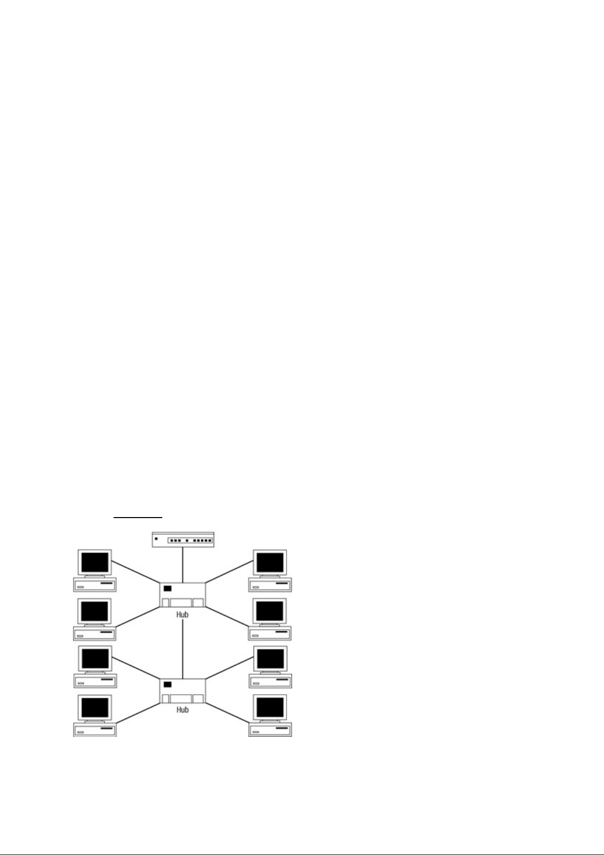
Many different types of physical cable media have been introduced over the years, such as Token Ring, FDDI,
and Ethernet. At one time, Token Ring was seen as a technically superior product and a viable alternative to
Ethernet. Many networks still contain Token Ring, but very few new Token Ring installations are being
implemented. One reason is that Token Ring is an IBM product with very little support from other vendors.
Also, the prices of Token Ring networks are substantially higher than those of Ethernet networks.
FDDI networks share some of the limitations of Token Ring. Like Token Ring, FDDI offers excellent benefits
in the area of high−speed performance and redundancy. Unfortunately, however, it has the same high
equipment and installation costs. More vendors are beginning to recognize FDDI and are offering support,
services, and installation for it—especially for network backbones.
Network backbones are generally high−speed links running between segments of the network. Normally,
backbone cable links run between two routers; but they can also be found between two switches or a switch
and a router.
Ethernet has by far overwhelmed the market and obtained the highest market share. Ethernet networks are
open−standards based, more cost−effective than other types of physical media, and have a large base of
vendors that supply the different Ethernet products. The biggest benefit that makes Ethernet so popular is the
large number of technical professionals who understand how to implement and support it.
Early networks were modeled on the peer−to−peer networking model. These worked well for the small
number of nodes, but as networks grew they evolved into the client/server network model of today. Let’s take
a look at these two models in more depth.
Peer−to−Peer Networking Model
A small, flat network or LAN often contains multiple segments connected with hubs, bridges, and repeaters.
This is an Open Systems Interconnection (OSI) Reference Model Layer 2 network that can actually be
connected to a router for access to a WAN connection. In this topology, every network node sees the
conversations of every other network node.
In terms of scalability, the peer−to−peer networking model has some major limitations—especially with the
technologies that companies must utilize to stay ahead in their particular fields. No quality of service,
prioritizing of data, redundant links, or data security can be implemented here, other than encryption. Every
node sees every packet on the network. The hub merely forwards the data it receives out of every port, as
shown in Figure 1.1.
Figure 1.1: A flat network topology.
Early networks consisted of a single LAN with a number of workstations running peer−to−peer networks and
sharing files, printers, and other resources. Peer−to−peer networks share data with one another in a
non−centralized fashion and can span only a very limited area, such as a room or building.
8
Page 25

Client/Server Network Model
Peer−to−peer model networks evolved into the client/server model, in which the server shares applications
and data storage with the clients in a somewhat more centralized network. This setup includes a little more
security, provided by the operating system, and ease of administration for the multiple users trying to access
data.
A LAN in this environment consists of a physical wire connecting the devices. In this model, LANs enable
multiple users in a relatively small geographical area to exchange files and messages, as well as to access
shared resources such as file servers and printers. The isolation of these LANs makes communication between
different offices or departments difficult, if not impossible. Duplication of resources means that the same
hardware and software have to be supplied to each office or department, along with separate support staff for
each individual LAN.
WANs soon developed to overcome the limitations of LANs. WANs can connect LANs across normal
telephone lines or other digital media (including satellites), thereby ignoring geographical limitations in
dispersing resources to network clients.
In a traditional LAN, many limitations directly impact network users. Almost anyone who has ever used a
shared network has had to contend with the other users of that network and experienced the impacts. These
effects include such things as slow network response times, making for poor network performance. They are
due to the nature of shared environments.
When collision rates increase, the usefulness of the bandwidth decreases. As applications begin having to
resend data due to excessive collisions, the amount of bandwidth used increases and the response time for
users increases. As the number of users increases, the number of requests for network resources rises, as well.
This increase boosts the amount of traffic on the physical network media and raises the number of data
collisions in the network. This is when you begin to receive more complaints from the network’s users
regarding response times and timeouts. These are all telltale signs that you need a switched Ethernet network.
Later in this chapter, we will talk more about monitoring networks and solutions to these problems. But before
we cover how to monitor, design, and upgrade your network, let’s look at the devices you will find in the
network.
The Pieces of Technology
In 1980, a group of vendors consisting of Digital Equipment Corporation (DEC), Intel, and Xerox created
what was known as the DIX standard. Ultimately, after a few modifications, it became the IEEE 802.3
standard. It is the 802.3 standard that most people associate with the term Ethernet.
The Ethernet networking technology was invented by Robert M. Metcalfe while he was working at the Xerox
Palo Alto Research Center in the early 1970s. It was originally designed to help support research on the
“office of the future.” At first, the network’s speed was limited to 3Mbps.
Ethernet is a multiaccess, packet−switched system with very democratic principles. The stations themselves
provide access to the network, and all devices on an Ethernet LAN can access the LAN at any time. Ethernet
signals are transmitted serially, one bit at a time, over a shared channel available to every attached station.
To reduce the likelihood of multiple stations transmitting at the same time, Ethernet LANs use a mechanism
known as Carrier Sense Multiple Access Collision Detection (CSMA/CD) to listen to the network and see if it
is in use. If a station has data to transmit, and the network is not in use, the station sends the data. If two
stations transmit at the same time, a collision occurs. The stations are notified of this event, and they instantly
reschedule their transmissions using a specially designed back−off algorithm. As part of this algorithm, each
station involved chooses a random time interval to schedule the retransmission of the frame. In effect, this
process keeps the stations from making transmission attempts at the same time and prevents a collision.
9
Page 26

After each frame transmission, all stations on the network contend equally for the next frame transmission.
This competition allows access to the network channel in a fair manner. It also ensures that no single station
can lock out the other stations from accessing the network. Access to the shared channel is determined by the
Media Access Control (MAC) mechanism on each Network Interface Card (NIC) located in each network
node. The MAC address uses a physical address which, in terms of the OSI Reference Model, contains the
lowest level address. This is the address used by a switch. The router at Layer 3 uses a protocol address,
which is referred as a logical address.
CSMA/CD is the tool that allows collisions to be detected. Each collision of frames on the network reduces
the amount of network bandwidth that can be used to send information across the physical wire. CSMA/CD
also forces every device on the network to analyze each individual frame and determine if the device was the
intended recipient of the packet. The process of decoding and analyzing each individual packet generates
additional CPU usage on each machine, which degrades each machine’s performance.
As networks grew in popularity, they also began to grow in size and complexity. For the most part, networks
began as small isolated islands of computers. In many of the early environments, the network was installed
over a weekend—when you came in on Monday, a fat orange cable was threaded throughout the organization,
connecting all the devices. A method of connecting these segments had to be derived. In the next few sections,
we will look at a number of approaches by which networks can be connected. We will look at repeaters, hubs,
bridges, and routers, and demonstrate the benefits and drawbacks to each approach.
Repeaters
The first LANs were designed using thick coaxial cables, with each station physically tapping into the cable.
In order to extend the distance and overcome other limitations on this type of installation, a device known as a
repeater is used. Essentially, a repeater consists of a pair of back−to−back transceivers. The transmit wire on
one transceiver is hooked to the receive wire on the other, so that bits received by one transceiver are
immediately retransmitted by the other.
Repeaters work by regenerating the signals from one segment to another, and they allow networks to
overcome distance limitations and other factors. Repeaters amplify the signal to further transmit it on the
segment because there is a loss in signal energy caused by the length of the cabling. When data travels
through the physical cable it loses strength the further it travels. This loss of the signal strength is referred to
as attenuation.
These devices do not create separate networks; instead, they simply extend an existing one. A standard rule of
thumb is that no more than three repeaters may be located between any two stations. This is often referred to
as the 5−4−3 rule, which states that no more than 5 segments may be attached by no more than 4 repeaters,
with no more than 3 segments populated with workstations. This limitation prevents propagation delay, which
is the time it takes for the packet to go from the beginning of the link to the opposite end.
As you can imagine, in the early LANs this method resulted in a host of performance and fault−isolation
problems. As LANs multiplied, a more structured approach called 10BaseT was introduced. This method
consists of attaching all the devices to a hub in the wiring closet. All stations are connected in a
point−to−point configuration between the interface and the hub.
Hubs
A hub, also known as a concentrator, is a device containing a grouping of repeaters. Similar to repeaters, hubs
are found at the Physical layer of the OSI Model. These devices simply collect and retransmit bits. Hubs are
used to connect multiple cable runs in a star−wired network topology into a single network. This design is
similar to the spokes of a wheel converging on the center of the wheel.
Many benefits derive from this type of setup, such as allowing interdepartmental connections between hubs,
extending the maximum distance between any pair of nodes on the network, and improving the ability to
isolate problems from the rest of the network.
10
Page 27

Six types of hubs are found in the network:
Active hubs—Act as repeaters and eliminate attenuation by amplifying the signals they replicate to all
•
the attached ports.
Backbone hubs—Collect other hubs into a single collection point. This type of design is also known
•
as a multitiered design. In a typical setup, servers and other critical devices are on high−speed Fast
Ethernet or Gigabit uplinks. This setup creates a very fast connection to the servers that the
lower−speed networks can use to prevent the server or the path to the server from being a bottleneck
in the network.
Intelligent hubs—Contain logic circuits that shut down a port if the traffic indicates that malformed
•
frames are the rule rather than the exception.
Managed hubs—Have Application layer software installed so that they can be remotely managed.
•
Network management software is very popular in organizations that have staff responsible for a
network spread over multiple buildings.
Passive hubs—Aid in producing attenuation. They do not amplify the signals they replicate to all the
•
attached ports. These are the opposite of active hubs.
Stackable hubs—Have a cable to connect hubs that are in the same location without requiring the data
•
to pass through multiple hubs. This setup is commonly referred to as daisy chaining.
In all of these types of hub configurations, one crucial problem exists: All stations share the bandwidth, and
they all remain in the same collision domain. As a result, whenever two or more stations transmit
simultaneously on any hub, there is a strong likelihood that a collision will occur. These collisions lead to
congestion during high−traffic loads. As the number of stations increases, each station gets a smaller portion
of the LAN bandwidth. Hubs do not provide microsegmentation and leave only one collision domain.
Bridges
A bridge is a relatively simple device consisting of a pair of interfaces with some packet buffering and simple
logic. The bridge receives a packet on one interface, stores it in a buffer, and immediately queues it for
transmission by the other interface. The two cables each experience collisions, but collisions on one cable do
not cause collisions on the other. The cables are in separate collision domains.
Note Some bridges are capable of connecting dissimilar topologies.
The term bridging refers to a technology in which a device known as a bridge connects two or more LAN
segments. Bridges are OSI Data Link layer, or Layer 2, devices that were originally designed to connect two
network segments. Multiport bridges were introduced later to connect more than two network segments, and
they are still in use in many networks today. These devices analyze the frames as they come in and make
forwarding decisions based on information in the frames themselves.
To do its job effectively, a bridge provides three separate functions:
Filtering the frames that the bridge receives to determine if the frame should be forwarded•
Forwarding the frames that need to be forwarded to the proper interface•
Eliminating attenuation by amplifying received data signals•
Bridges learn the location of the network stations without any intervention from a network administrator or
any manual configuration of the bridge software. This process is commonly referred to as self−learning.
When a bridge is turned on and begins to operate, it examines the MAC addresses located in the headers of
frames passed through the network. As the traffic passes through the bridge, the bridge builds a table of
known source addresses, assuming the port from which the bridge received the frame is the port to which the
device is a sending device is attached.
In this table, an entry exists that contains the MAC address of each node along with the bridge interface and
port on which it resides. If the bridge knows that the destination is on the same segment as the source, it drops
the packet because there is no need to transmit it. If the bridge knows that the destination is on another
11
Page 28

segment, it transmits the packet on that segment or port to that segment only. If the bridge does not know the
destination segment, the bridge transmits a copy of the frame to all the interface ports in the source segment
using a technique known as flooding. For each packet an interface receives, the bridge stores in its table the
following information:
The frame’s source address•
The interface the frame arrived on•
The time at which the switch port received the source address and entered it into the switching table•
Note Bridges and switches are logically equivalent.
There are four kinds of bridges:
Transparent bridge—Primarily used in Ethernet environments. They are called transparent bridges
•
because their presence and operation are transparent to network hosts. Transparent bridges learn and
forward packets in the manner described earlier.
Source−route bridge—Primarily used in Token Ring environments. They are called source−route
•
bridges because they assume that the complete source−to−destination route is placed in frames sent
by the source.
Translational bridge—Translators between different media types, such as Token Ring and Ethernet.•
Source−route transparent bridge—A combination of transparent bridging and source−route bridging
•
that enables communication in mixed Ethernet and Token Ring environments.
Broadcasts are the biggest problem with bridges. Some bridges help reduce network traffic by filtering
packets and allowing them to be forwarded only if needed. Bridges also forward broadcasts to devices on all
segments of the network. As networks grow, so does broadcast traffic. Instead of frames being broadcast
through a limited number of devices, bridges often allow hundreds of devices on multiple segments to
broadcast data to all the devices. As a result, all devices on all segments of the network are now processing
data intended for one device. Excessive broadcasts reduce the amount of bandwidth available to end users.
This situation causes bandwidth problems called network broadcast storms. Broadcast storms occur when
broadcasts throughout the LAN use up all available bandwidth, thus grinding the network to a halt.
Network performance is most often affected by three types of broadcast traffic: inquiries about the availability
of a device, advertisements for a component’s status on the network, and inquiries from one device trying to
locate another device. The following are the typical types of network broadcasts:
Address Resolution Protocol (ARP)•
Internetwork Packet Exchange (IPX) Get Nearest Server (GNS) requests•
IPX Service Advertising Protocol (SAP)•
Multicast traffic broadcasts•
NetBIOS name requests•
These broadcasts are built into the network protocols and are essential to the operation of the network devices
using these protocols.
Due to the overhead involved in forwarding packets, bridges also introduce a delay in forwarding traffic. This
delay is known as latency. Latency delay is measured from the moment a packet enters the input port on the
switch until the time the bridge forwards the packet out the exit port. Bridges can introduce 20 to 30 percent
loss of throughput for some applications. Latency is a big problem with some timing−dependent technologies,
such as mainframe connectivity, video, or voice.
High levels of latency can result in loss of connections and noticeable video and voice degradation. The
inherent problems of bridging over multiple segments including those of different LAN types with Layer 2
devices became a problem to network administrators. To overcome these issues, a device called a router,
operating at OSI Layer 3, was introduced.
12
Page 29
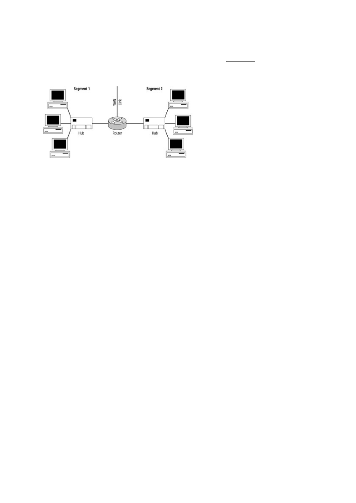
Routers
Routers are devices that operate at Layer 3 of the OSI Model. Routers can be used to connect more than one
Ethernet segment with or without bridging. Routers perform the same basic functions as bridges and also
forward information and filter broadcasts between multiple segments. Figure 1.2 shows routers segmenting
multiple network segments. Using an OSI network Layer 3 solution, routers logically segment traffic into
subnets.
Figure 1.2: Routers connecting multiple segments.
Routers were originally introduced to connect dissimilar network media types as well as to provide a means to
route traffic, filter broadcasts across multiple segments, and improve overall performance. This approach
eliminated broadcasts over multiple segments by filtering broadcasts. However, routers became a bottleneck
in some networks and also resulted in a loss of throughput for some types of traffic.
When you are connecting large networks, or when you are connecting networks to a WAN, routers are very
important. Routers will perform media conversion, adjusting the data link protocol as necessary. With a
router, as well as with some bridges, you can connect an Ethernet network and a Token Ring network.
Routers do have some disadvantages. The cost of routers is very high, so they are an expensive way to
segment networks. If protocol routing is necessary, you must pay this cost. Routers are also difficult to
configure and maintain, meaning that you will have a difficult time keeping the network up and running.
Knowledgeable workers who understand routing can be expensive.
Routers are also somewhat limited in their performance, especially in the areas of latency and forwarding
rates. Routers add about 40 percent additional latency from the time packets arrive at the router to the time
they exit the router. Higher latency is primarily due to the fact that routing requires more packet assembly and
disassembly. These disadvantages force network administrators to look elsewhere when designing many large
network installations.
Switches
A new option had to be developed to overcome the problems associated with bridges and routers. These new
devices were called switches. The term switching was originally applied to packet−switch technologies, such
as Link Access Procedure, Balanced (LAPB); Frame Relay; Switched Multimegabit Data Service (SMDS);
and X.25. Today, switching is more commonly associated with LAN switching and refers to a technology that
is similar to a bridge in many ways.
Switches allow fast data transfers without introducing the latency typically associated with bridging. They
create a one−to−one dedicated network segment for each device on the network and interconnect these
segments by using an extremely fast, high−capacity infrastructure that provides optimal transport of data on a
LAN; this structure is commonly referred to as a backplane. This setup reduces competition for bandwidth on
the network, allows maximum utilization of the network, and increases flexibility for network designers and
implementers.
Ethernet switches provide a number of enhancements over shared networks. Among the most important is
microsegmentation, which is the ability to divide networks into smaller and faster segments that can operate at
the maximum possible speed of the wire (also known as wire−speed).
13
Page 30
To improving network performance, switches must address three issues:
They must stop unneeded traffic from crossing network segments.•
They must allow multiple communication paths between segments.•
They cannot introduce performance degradation.•
Routers are also used to improve performance. Routers are typically attached to switches to connect multiple
LAN segments. A switch forwards the traffic to the port on the switch to which the destination device is
connected, which in turn reduces the traffic to the other devices on the network. Information from the sending
device is routed directly to the receiving device. No device other than the router, switch, and end nodes sees or
processes the information.
The network now becomes less saturated, more secure, and more efficient at processing information, and
precious processor time is freed on the local devices. Routers today are typically placed at the edge of the
network and are used to connect WANs, filter traffic, and provide security. See Figure 1.3.
Figure 1.3: Routers and switches
Like bridges, switches perform at OSI Layer 2 by examining the packets and building a forwarding table
based on what they hear. Switches differ from bridges by helping to meet the following needs for network
designers and administrators:
Provide deterministic paths•
Relieve network bottlenecks•
Provide deterministic failover for redundancy•
Allow scalable network growth•
Provide fast convergence•
Act as a means to centralize applications and servers•
Have the capacity to reduce latency•
Network Design
When designing or upgrading your network, you need to keep some basic rules of segmenting in mind. You
segment your network primarily to relieve network congestion and route data as quickly and efficiently as
possible. Segmentation is often necessary to satisfy the bandwidth requirements of a new application or type
of information that the network needs to support. Other times, it may be needed due to the increased traffic on
the segment or subnet. You should also plan for increased levels of network usage or unplanned increases in
network population.
Some areas you need to consider are the types of nodes, user groups, security needs, population of the
network, applications used, and the network needs for all the interfaces on the network. When designing your
network, you should create it in a hierarchical manner. Doing so provides you with the ability to easily make
additions to your network. Another important consideration should be how your data flows through the
network.
For example, let’s say your users are intermingled with your servers in the same geographical location. If you
create a switched network in which the users’ data must be switched through a number of links to another
geographical area and then back again to create a connection between the users and file servers, you have not
14
Page 31

designed the most efficient path to the destination.
Single points of failure need to be analyzed, as well. As we stated earlier, every large−network user has
suffered through his or her share of network outages and downtime. By analyzing all the possible points of
failure, you can implement redundancy in the network and avoid many network outages. Redundancy is the
addition of an alternate path through the network. In the event of a network failure, the alternate paths can be
used to continue forwarding data throughout the network.
The last principle that you should consider when designing your network is the behavior of the different
protocols. The actual switching point for data does not have to be the physical wire level. Your data can be
rerouted at the Data Link and Network layers, as well. Some protocols introduce more network traffic than
others. Those operating at Layer 2 can be encapsulated or tagged to create a Layer−3−like environment. This
environment allows the implementation of switching, and thereby provides security, protocol priority, and
Quality of Service (QoS) features through the use of Application−Specific Integrated Circuits (ASICs) instead
of the CPU on the switch. ASICs are much faster than CPUs. ASICs are silicon chips that provide only one or
two specific tasks faster than a CPU. Because they process data in silicon and are assigned to a certain task,
less processing time is needed, and data is forwarded with less latency and more efficiency to the end
destinations.
In order to understand how switches work, we need to understand how collision domains and broadcast
domains differ.
Collision Domains
A switch can be considered a high−speed multiport bridge that allows almost maximum wire−speed transfers.
Dividing the local geographical network into smaller segments reduces the number of interfaces in each
segment. Doing so will increase the amount of bandwidth available to all the interfaces. Each smaller segment
is considered a collision domain.
In the case of switching, each port on the switch is its own collision domain. The most optimal switching
configuration places only one interface on each port of a switch, making the collision domain two nodes: the
switch port interface and the interface of the end machine.
Let’s look at a small collision domain consisting of two PCs and a server, shown in Figure 1.4. Notice that if
both PCs in the network transmit data at the same time, the data will collide in the network because all three
computers are in their own collision domain. If each PC and server was on its own port on the switch, each
would be in its own collision domain.
Figure 1.4: A small collision domain consisting of two PCs sending data simultaneously to a server.
Switch ports are assigned to virtual LANs (VLANs) to segment the network into smaller broadcast domains.
If you are using a node attached to a switch port assigned to a VLAN, broadcasts will only be received from
members of your assigned VLAN. When the switch is set up and each port is assigned to a VLAN, a
broadcast sent in VLAN 1 is seen by those ports assigned to VLAN 1 even if they are on other switches
attached by trunk links. A switch port can be a member of only one VLAN and requires a Layer 3 device such
as an internal route processor or router to route data from one VLAN to another.
15
Page 32

Although the nodes on each port are in their own collision domain, the broadcast domain consists of all of the
ports assigned to a particular VLAN. Therefore, when a broadcast is sent from a node in VLAN 1, all the
devices attached to ports assigned to VLAN 1 will receive that broadcast. The switch segments the users
connected to other ports, thereby preventing data collisions. For this reason, when traffic remains local to each
segment or workgroup, each user has more bandwidth available than if all the nodes are in one segment.
On a physical link between the port on the switch and a workstation in a VLAN with very few nodes, data can
be sent at almost 100 percent of the physical wire speed. The reason? Virtually no data collisions. If the
VLAN contains many nodes, the broadcast domain is larger and more broadcasts must be processed by all
ports on the switch belonging to each VLAN. The number of ports assigned to a VLAN make up the
broadcast domain, which is discussed in the following section.
Broadcast Domains
In switched environments, broadcast domains consist of all the ports or collision domains belonging to a
VLAN. In a flat network topology, your collision domain and your broadcast domain are all the interfaces in
your segment or subnet. If no devices (such as a switch or a router) divide your network, you have only one
broadcast domain. On some switches, the number of broadcast domains or VLANs that can be configured is
almost limitless. VLANs allow a switch to divide the network segment into multiple broadcast domains. Each
port becomes its own collision domain. Figure 1.5 shows an example of a properly switched network.
Figure 1.5: An example of a properly switched network.
Note Switching technology complements routing technology, and each has its place in the network. The value
of routing technology is most noticeable when you get to larger networks that utilize WAN solutions in
the network environment.
Why Upgrade to Switches?
As an administrator, you may not realize when it is time to convert your company to a switched network and
implement VLANs. You may also not be aware of the benefits that can occur from replacing your Layer 2
hubs and bridges with switches, or how the addition of some modules in your switches to implement routing
and filtering ability can help improve your network’s performance.
When your flat topology network starts to slow down due to traffic, collisions, and other bottlenecks, you may
want to investigate the problems. Your first reaction is to find out what types of data are flowing through your
network. If you are in command of the network sniffer or other such device, you may begin to find
over−utilization errors on the sniffer occurring when the Ethernet network utilization reaches above only 40
percent.
Why would this happen at such a low utilization percentage on the network? Peak efficiency on a flat
topology Ethernet network is about 40 percent utilization. Sustained utilization above this level is a strong
indicator that you may want to upgrade the physical network into a switched environment.
When you start to notice that your state−of−the−art Pentiums are performing poorly, many network
administrators don’t realize the situation may be due to the hundreds of other computers on their flat hub and
16
Page 33

bridged networks. To resolve the issue, your network administrator may even upgrade your PC to a faster
CPU or more RAM. This allows your PC to generate more input/output (I/O), increasing the saturation on the
network. In this type of environment, every data packet is sent to every machine, and each station has to
process every frame on the network.
The processors in the PCs handle this task, taking away from the processing power needed for other tasks.
Every day, I visit users and networks with this problem. When I upgrade them to a switched network, it is
typically a weekend job. The users leave on Friday with their high−powered Pentiums stacked with RAM
acting like 486s. When they come back Monday morning, we hear that their computers boot up quickly and
run faster, and that Internet pages come up instantly.
In many cases, slow Internet access times were blamed on the users’ WAN connections. The whole time, the
problem wasn’t their WAN connections—it was their LAN saturated to a grinding halt with frames from
every interface on the network.
When network performance gets this bad, it’s time to call in a Cisco consultant or learn how to implement
switching. Either way, you are reading this book because you are very interested in switching or in becoming
Cisco certified. Consider yourself a network hero of this generation in training.
To fix the immediate problems on your 10BaseT network with Category 3 or Category 4 cabling, you might
need to upgrade to Category 5 cabling and implement a Fast Ethernet network. Then you need to ask yourself,
is this only a temporary solution for my network? What types of new technologies are we considering? Are
we going to upgrade to Windows 2000? Will we be using Web services or implementing Voice Over IP? Do
we have any requirements for using multicast, unicast, video conferencing, or CAD applications? The list of
questions goes on. Primarily, you need to ask yourself if this is a temporary solution or one that will stand the
test of time.
Unshielded Twisted−Pair Cable
Category 3 unshielded twisted−pair (UTP) is cable certified for bandwidths of up to 10Mbps with signaling
rates of up to 16MHz. Category 4 UTP cable is cable certified for bandwidths of up to 16Mbps with signaling
rates up to 20MHz. Category 4 cable is classified as voice and data grade cabling. Category 5 cabling is cable
certified for bandwidths of up to 100Mbps and signaling rates of up to 100MHz. New cabling standards for
Category 5e and Category 6 cable support bandwidths of up to 1Gbps.
In many cases, network administrators don’t realize that implementing a switched network will allow your
network to run at almost wire speed. Upgrading the backbone (not the wiring), eliminating the data collisions,
making the network segments smaller, and getting those users off hubs and bridges is the answer. In terms of
per−port costs, this is usually a much cheaper solution. It’s also a solution you can grow with. Of course, a
100Mbps network never hurts; but even a switched 10BaseT network that has been correctly implemented can
have almost the same effect of providing your network with increased performance.
Network performance is usually measured by throughput. Throughput is the overall amount of data traffic that
can be carried by the physical lines through the network. It is measured by the maximum amount of data that
can pass through any point in your network without suffering packet loss or collisions.
Packet loss is the total number of packets transmitted at the speed of the physical wire minus the number that
arrive correctly at their destination. When you have a large percentage of packet losses, your network is
functioning less efficiently than it would if the multiple collisions of the transmitted data were eliminated.
The forwarding rate is another consideration in network throughput. The forwarding rate is the number of
packets per second that can be transmitted on the physical wire. For example, if you are sending 64−byte
packets on a 10BaseT Ethernet network, you can transmit a maximum of about 14,880 packets per second.
17
Page 34

Poorly designed and implemented switched networks can have awful effects. Let’s take a look at the effects of
a flat area topology and how we can design, modify, and upgrade Ethernet networks to perform as efficiently
as possible.
Properly Switched Networks
Properly switched networks use the Cisco hierarchical switching model to place switches in the proper
location in the network and apply the most efficient functions to each. In the model you will find switches in
three layers:
Access layer•
Distribution layer•
Core layer•
Note Chapter 2 will introduce the layers at which each switch can be found and the basic configuration steps
for both of the command line interfaces.
The Access layer’s primary function is to connect to the end−user’s interface. It routes traffic between ports
and broadcasts collision domain traffic to its membership broadcast domain. It is the access point into the
network for the end users. It can utilize lower−end switches such as the Catalyst 1900, 2800, 2900, 3500,
4000, and 5000 series switches.
The Access layer switch blocks meet at the Distribution layer. It uses medium−end switches with a little more
processing power and stronger ASICs. The function of this layer is to apply filters, queuing, security, and
routing in some networks. It is the main processor of frames and packets flowing through the network.
Switches found at this layer belong to the 5500, 6000, and 6500 series.
The Core layer’s only function is to route data between segments and switch blocks as quickly as possible. No
filtering or queuing functions should be applied at this layer. The highest−end Cisco Catalyst switches are
typically found at this layer, such as the 5500, 6500, 8500, 8600 GSR, and 12000 GSR series switches.
How you configure your broadcast and collision domains—whether in a switched network or a flat network
topology—can have quite an impact on the efficiency of your network. Let’s take a look at how utilization is
measured and the different effects bandwidth can have on different media types and networks.
Network Utilization
Network administrators vary on the utilization percentage values for normal usage of the network. Table 1.1
shows the average utilization that should be seen on the physical wire. Going above these averages of network
utilization on the physical wire is a sign that a problem exists in the network, that you need to make changes
to the network configuration, or that you need to upgrade the network.
Table 1.1: The average limits in terms of physical wire utilization. Exceeding these values indicates a network
problem.
Utilization (%) Medium Type
100 Full duplex
90 to 100 FDDI
90 to 100 Switched LAN segments
60 to 65 WAN links
35 to 45 Non−switched Ethernet segments or subnets
5 to 7 Collisions
You can use a network monitor such as a sniffer to monitor your utilization and the type of traffic flowing
through your network. Devices such as WAN probes let you monitor the traffic on the WAN.
18
Page 35

Switched Forwarding
Switches route data based on the destination MAC address contained in the frame’s header. This approach
allows switches to replace Layer 2 devices such as hubs and bridges.
After a frame is received and the MAC address is read, the switch forwards data based on the switching mode
the switch is using. This strategy tends to create very low latency times and very high forwarding rates.
Switches use three switching modes to forward information through the switching fabric:
Store−and−forward•
Cut−through•
FragmentFree•
Tip Switching fabric is the route data takes to get from the input port on the switch to the output port
on the switch. The data may pass through wires, processors, buffers, ASICs, and many other
components.
Store−and−Forward Switching
Pulls the entire packet received into its onboard buffers, reads the entire packet, and calculates its cyclic
redundancy check (CRC). It then determines if the packet is good or bad. If the CRC calculated on the packet
matches the CRC calculated by the switch, the destination address is read and the packet is forwarded out the
correct port on the switch. If the CRC does not match the packet, the packet is discarded. Because this type of
switching waits for the entire packet before forwarding, latency times can become quite high, which can result
in some delay of network traffic.
Cut−Through Switching
Sometimes referred to as realtime switching or FastForward switching, cut−through switching was developed
to reduce the latency involved in processing frames as they arrive at the switch and are forwarded on to the
destination port. The switch begins by pulling the frame header into its network interface card buffer. As soon
as the destination MAC address is known (usually within the first 13 bytes), the switch forwards the frame out
the correct port.
This type of switching reduces latency inside the switch; however, if the frame is corrupt because of a late
collision or wire interference, the switch will still forward the bad frame. The destination receives the bad
frame, checks its CRC, and discards it, forcing the source to resend the frame. This process will certainly
waste bandwidth; and if it occurs too often, major impacts can occur on the network.
In addition, cut−through switching is limited by its inability to bridge different media speeds. In particular,
some network protocols (including NetWare 4.1 and some Internet Protocol [IP] networks) use windowing
technology, in which multiple frames may be sent without a response. In this situation, the latency across a
switch is much less noticeable, so the on−the−fly switch loses its main competitive edge. In addition, the lack
of error checking poses a problem for large networks. That said, there is still a place for the fast cut−through
switch for smaller parts of large networks.
FragmentFree Switching
Also known as runtless switching, FragmentFree switching was developed to solve the late−collision problem.
These switches perform a modified version of cut−through switching. Because most corruption in a packet
occurs within the first 64 bytes, the switch looks at the entire first 64 bytes to get the destination MAC
address, instead of just reading the first 13 bytes. The minimum valid size for an Ethernet frame is 64 bytes.
By verifying the first 64 bytes of the frame, the switch then determines if the frame is good or if a collision
occurred during transit.
19
Page 36
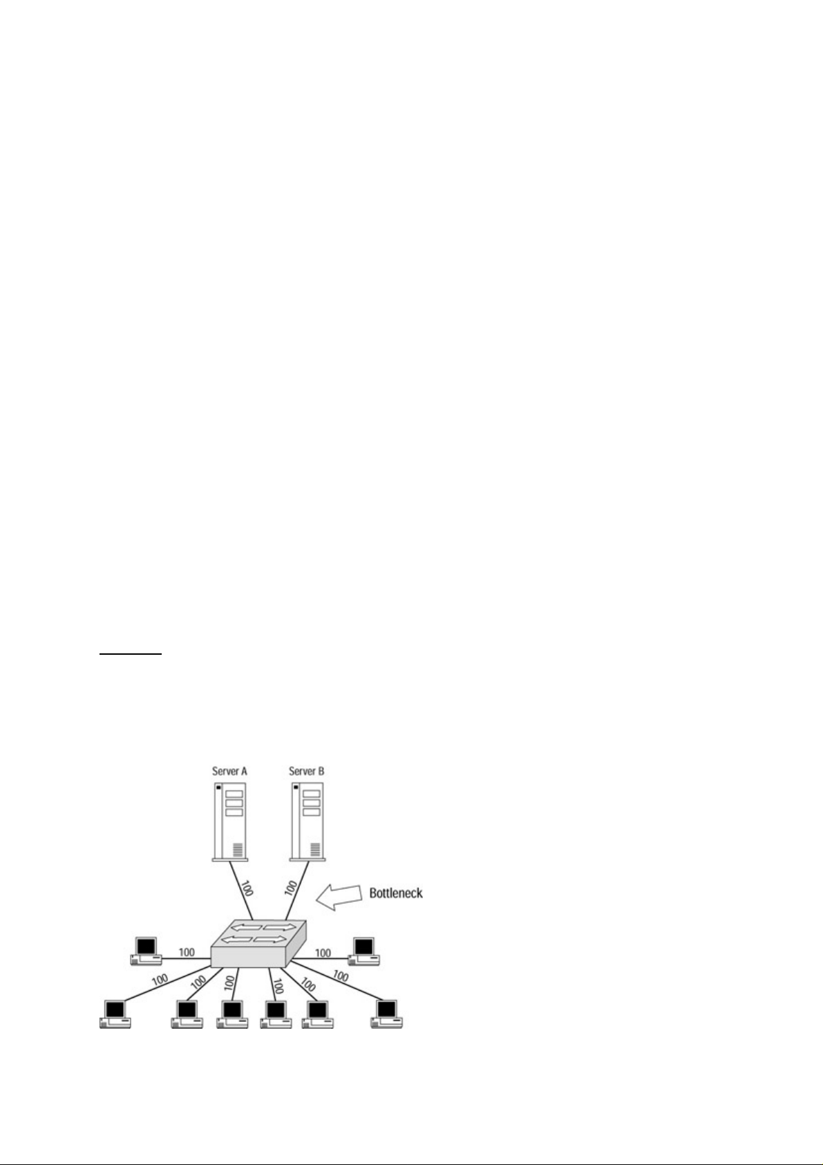
Combining Switching Methods
To resolve the problems associated with the switching methods discussed so far, a new method was
developed. Some switches, such as the Cisco Catalyst 1900, 2820, and 3000 series, begin with either
cut−through or FragmentFree switching. Then, as frames are received and forwarded, the switch also checks
the frame’s CRC. Although the CRC may not match the frame itself, the frame is still forwarded before the
CRC check and after the MAC address is reached. The switch performs this task so that if too many bad
frames are forwarded, the switch can take a proactive role, changing from cut−through mode to
store−and−forward mode. This method, in addition to the development of high−speed processors, has reduced
many of the problems associated with switching.
Only the Catalyst 1900, 2820, and 3000 series switches support cut−through and FragmentFree switching.
You might ponder the reasoning behind the faster Catalyst series switches not supporting this seemingly faster
method of switching. Well, store−and−forward switching is not necessarily slower than cut−through
switching—when switches were first introduced, the two modes were quite different. With better processors
and integrated−circuit technology, store−and−forward switching can perform at the physical wire limitations.
This method allows the end user to see no difference in the switching methods.
Switched Network Bottlenecks
This section will take you step by step through how bottlenecks affect performance, some of the causes of
bottlenecks, and things to watch out for when designing your network. A bottleneck is a point in the network
at which data slows due to collisions and too much traffic directed to one resource node (such as a server). In
these examples, I will use fairly small, simple networks so that you will get the basic strategies that you can
apply to larger, more complex networks.
Let’s start small and slowly increase the network size. We’ll take a look at a simple way of understanding how
switching technology increases the speed and efficiency of your network. Bear in mind, however, that
increasing the speed of your physical network increases the throughput to your resource nodes and doesn’t
always increase the speed of your network. This increase in traffic to your resource nodes may create a
bottleneck.
Figure 1.6 shows a network that has been upgraded to 100Mbps links to and from the switch for all the nodes.
Because all the devices can send data at 100Mbps or wire−speed to and from the switch, a link that receives
data from multiple nodes will need to be upgraded to a faster link than all the other nodes in order to process
and fulfill the data requests without creating a bottleneck. However, because all the nodes—including the file
servers—are sending data at 100Mbps, the link between the file servers that is the target for the data transfers
for all the devices becomes a bottleneck in the network.
Figure 1.6: A switched network with only two servers. Notice that the sheer number of clients sending data to
the servers can overwhelm the cable and slow the data traffic.
20
Page 37

Many types of physical media topologies can be applied to this concept. In this demonstration, we will utilize
Ethernet 100BaseT. Ethernet 10BaseT and 100BaseT are most commonly found in the networks of today.
We’ll make an upgrade to the network and alleviate our bottleneck on the physical link from the switch to
each resource node or server. By upgrading this particular link to a Gigabit Ethernet link, as shown in Figure
1.7, you can successfully eliminate this bottleneck.
Figure 1.7: The addition of a Gigabit Ethernet link on the physical link between the switch and the server.
It would be nice if all network bottleneck problems were so easy to solve. Let’s take a look at a more complex
model. In this situation, the demand nodes are connected to one switch and the resource nodes are connected
to another switch. As you add additional users to switch A, you’ll find out where our bottleneck is. As you can
see from Figure 1.8, the bottleneck is now on the trunk link between the two switches. Even if all the switches
have a VLAN assigned to each port, a trunk link without VTP pruning enabled will send all the VLANs to the
next switch.
Figure 1.8: : A new bottleneck on the trunk link between the two switches.
To resolve this issue, you could implement the same solution as the previous example and upgrade the trunk
between the two switches to a Gigabit Ethernet. Doing so would eliminate the bottleneck. You want to put
switches in place whose throughput is never blocked by the number of ports. This solution is referred to as
using non−blocking switches.
Non−Blocking Switch vs. Blocking Switch
21
Page 38

We call a switch a blocking switch when the switch bus or components cannot handle the theoretical
maximum throughput of all the input ports combined. There is a lot of debate over whether every switch
should be designed as a non−blocking switch; but for now this situation is only a dream, considering the
current pricing of non−blocking switches.
Let’s get even more complicated and introduce another solution by implementing two physical links between
the two switches and using full−duplexing technology. Full duplex essentially means that you have two
physical wires from each port—data is sent on one link and received on another. This setup not only virtually
guarantees a collision−free connection, but also can increase your network traffic to almost 100 percent on
each link.
You now have 200 percent throughput by utilizing both links. If you had 10Mbps on the wire at half duplex,
by implementing full duplex you now have 20Mbps flowing through the wires. The same thing goes with a
100BaseT network: Instead of 100Mbps, you now have a 200Mbps link.
Tip If the interfaces on your resource nodes can implement full duplex, it can also be a secondary solution for
your servers.
Almost every Cisco switch has an acceptable throughput level and will work well in its own layer of the Cisco
hierarchical switching model or its designed specification. Implementing VLANs has become a popular
solution for breaking down a segment into smaller collision domains.
Internal Route Processor vs. External Route Processor
Routing between VLANs has been a challenging problem to overcome. In order to route between VLANs,
you must use a Layer 3 route processor or router. There are two different types of route processors: an
external route processor and an internal route processor. An external route processor uses an external router to
route data from one VLAN to another VLAN. An internal route processor uses internal modules and cards
located on the same device to implement the routing between VLANs.
Now that you have a pretty good idea how a network should be designed and how to monitor and control
bottlenecks, let’s take a look at the general traffic rule and how it has changed over time.
The Rule of the Network Road
Network administrators and designers have traditionally strived to design networks using the 80/20 rule.
Using this rule, a network designer would try to design a network in which 80 percent of the traffic stayed on
local segments and 20 percent of the traffic went on the network backbone.
This was an effective design during the early days of networking, when the majority of LANs were
departmental and most traffic was destined for data that resided on the local servers. However, it is not a good
design in today’s environment, where the majority of traffic is destined for enterprise servers or the Internet.
A switch’s ability to create multiple data paths and provide swift, low−latency connections allows network
administrators to permit up to 80 percent of the traffic on the backbone without causing a massive overload of
the network. This ability allows for the introduction of many bandwidth−intensive uses, such as network
video, video conferencing, and voice communications.
Multimedia and video applications can demand as much as 1.5Mbps or more of continuous bandwidth. In a
typical environment, users can rarely obtain this bandwidth if they share an average 10Mbps network with
dozens of other people. The video will also look jerky if the data rate is not sustained. In order to support this
application, a means of providing greater throughput is needed. The ability of switches to provide dedicated
bandwidth at wire−speed meets this need.
22
Page 39

Switched Ethernet Innovations
Around 1990, many vendors offered popular devices known as intelligent multiport bridges; the first known
usage of the term switch was the Etherswitch, which Kalpana brought to the market in 1990. At the time, these
devices were used mainly to connect multiple segments—they usually did very little to improve performance
other than the inherent benefits bridges provide, such as filtering and broadcast suppression.
Kalpana changed that by positioning its devices as performance enhancers. A number of important features
made the Kalpana switches popular, such as using multiple transmission paths for network stations and
cut−through switching.
Cut−through switching reduced the delay problems associated with standard bridges by providing the means
to have multiple transmissions paths to network devices. Each device could have its own data path to the
switch and did not need to be in a shared environment.
Kalpana was able to do this by dedicating one pair of the station wiring to transmitting data and one pair to
receiving data. This improvement allowed the Kalpana designers to ignore the constraints of collision
detection and carrier sense, because the cables were dedicated to one station. Kalpana continued its history of
innovation with the introduction in 1993 of full−duplex Ethernet.
Full−Duplex Ethernet
Prior to the introduction of full−duplex (FDX) Ethernet, Ethernet stations could either transmit or receive
data; they could not do both at the same time, because there was no way to ensure a collision−free
environment. This was known as half−duplex (HDX) operation.
FDX has been a feature of WANs for years, but only the advent of advances in LAN switching technology
made it practical to now consider FDX on the LAN. In FDX operation, both the transmission and reception
paths can be used simultaneously. Because FDX operation uses a dedicated link, there are no collisions, which
greatly simplifies the MAC protocol. Some slight modifications in the way the packet header is formatted
enable FDX to maintain compatibility with HDX Ethernet.
You don’t need to replace the wiring in a 10BaseT network, because FDX operation runs on the same
two−pair wiring used by 10BaseT. It simultaneously uses one pair for transmission and another pair for
reception. A switched connection has only two stations: the station itself and the switch port. This setup
makes simultaneous transmission possible and has the net effect of doubling a 10Mbps LAN.
This last point is an important one. In theory, FDX operation can provide double the bandwidth of HDX
operation, giving 10Mbps speeds in each direction. However, achieving this speed would require that the two
stations have a constant flow of data and that the applications themselves would benefit from a two−way data
flow. FDX links are extremely beneficial in connecting switches to each other. If there were servers on both
sides of the link between switches, the traffic between switches would tend to be more symmetrical.
Fast Ethernet
Another early innovation in the switching industry was the development of Fast Ethernet. Ethernet as a
technology has been around since the early 1970s, but by the early 1990s its popularity began to wane.
Competing technologies such as FDDI running at 100Mbps showed signs of overtaking Ethernet as a de facto
standard, especially for high−speed backbones.
Grand Junction, a company founded by many of the early Ethernet pioneers, proposed a new Ethernet
technology that would run at 10 times the 10Mbps speed of Ethernet. They were joined by most of the top
networking companies—with the exception of Hewlett−Packard (HP), which had a competing product. HP’s
product, known as 100Mbps VG/AnyLAN, was in most respects far superior to the product proposed by
Grand Junction. It had a fatal flaw, though: It was incompatible with existing Ethernet standards and was not
23
Page 40

backward compatible to most of the equipment in use at the time. Although the standards bodies debated the
merits of each of the camps, the marketplace decided for them. Fast Ethernet is the overwhelming winner, so
much so that even HP sells Fast Ethernet on almost all its products.
Note In 1995, Cisco purchased both Kalpana and Grand Junction and incorporated their innovations into its
hardware. These devices became the Catalyst line of Cisco products.
Gigabit Ethernet
In order to implement Gigabit Ethernet (GE), the CSMA/CD method was changed slightly to maintain a
200−meter collision diameter at gigabit−per−second data rates. This slight modification prevented Ethernet
packets from completing transmission before the transmitting station sensed a collision, which would violate
the CSMA/CD rule.
GE maintains a packet length of 64 bytes, but provides additional modifications to the Ethernet specification.
The minimum CSMA/CD carrier time and the Ethernet slot time have been extended from 64 bytes to 512
bytes. Also, packets smaller than 512 bytes have an extra carrier extension added to them. These changes,
which can impact the performance of small packets, have been offset by implementing a feature called packet
bursting, which allows servers, switches, and other devices to deliver bursts of small packets in order to utilize
the available bandwidth.
Because it follows the same form, fit, and function as its 10− and 100Mbps predecessors, GE can be
integrated seamlessly into existing Ethernet and Fast Ethernet networks using LAN switches or routers to
adapt between the different physical line speeds. Because GE is Ethernet, only faster, network managers will
find the migration from Fast Ethernet to Gigabit Ethernet to be as smooth as the migration from Ethernet to
Fast Ethernet.
Avoiding Fork−Lift Upgrades
Although dedicated switch connections provide the maximum benefits for network users, you don’t want to
get stuck with fork−lift upgrades. In a fork−lift upgrade, you pay more to upgrade your computer or
networking equipment than it would cost to buy the equipment already installed. The vendor knows that you
are not going to buy all new equipment, so the vendor sells you the upgrade at an enormous price. In order to
exchange it for the bigger, better, faster equipment It may sometimes be necessary to support legacy
equipment.
Fortunately for Ethernet switches you can provide connectivity in a number of ways. You can attach shared
hubs to any port on the switch in the same manner that you connect end stations. Doing so makes for a larger
collision domain, but you avoid paying the high costs of upgrades.
Typically, your goal would be to migrate toward single−station segments as bandwidth demands increase.
This migration will provide you with the increased bandwidth you need without wholesale replacement of
existing equipment or cabling.
In this lower cost setup, a backbone switch is created in which each port is attached to the now−larger
collision domain or segment. This switch replaces existing connections to routers or bridges and provides
communication between each of the shared segments.
The Cisco IOS
The Cisco Internetwork Operating System (IOS) is the kernel of Cisco routers and switches. Not all Cisco
24
Page 41

devices run the same IOS. Some use a graphical interface, some use a Set/Clear command−line interface, and
some use a Cisco Command Line Interface (CLI). Cisco has acquired more devices than they have designed
and built themselves. Therefore, Cisco has adapted the operating systems designed for each device they have
acquired to use the protocols and standards of the company. Almost all Cisco routers run the same IOS, but
only about half of the switches currently run the Cisco CLI IOS.
Knowing what configuration mode you are in and how to enter each configuration mode on the Cisco CLI is
important. Recognizing what each mode configures will aid you in using the proper configuration mode. The
Set/Clear command−based IOS is similar in modes, but uses the enable, set, show, and clear commands
(covered in the next chapter).
Connecting to the Switch
You can connect to a Cisco switch to configure the switch, verify the configuration, or check statistics.
Although there are different ways of connecting to a Cisco switch, typically you would connect to its console
port.
In lower−end Cisco switches, the console port is usually an RJ−45 connection on the back of the switch. On a
higher−end switch, you may find console ports on the line cards such as a Supervisor Engine. By default there
is no password set on the console port.
Another way to connect to a Cisco switch or router is through an auxiliary port. This is basically the same as
connecting through a console port, but it allows you to connect remotely by using a modem. This means you
can dial up a remote switch and perform configuration changes, verify the configuration, or check statistics.
A third way to connect to a Cisco switch is through the program Telnet. Telnet is a program that emulates a
dumb terminal. You can use Telnet to connect to any active port on the switch, such as an Ethernet or serial
port.
Cisco also allows you to configure the switch by using Switch Manager, which is a way of configuring your
switch through a Web browser using HTTP. This method creates a graphical interface for configuring your
switch. The Switch Manager allows you to perform most of the same configurations as you can with the CLI.
Powering Up the Switch
When you first power up a Cisco switch, it runs the power on self test (POST), which runs diagnostics on the
internal workings of the switch. If the switch passes this test, it will look for and load the Cisco IOS from
Flash memory if a file is present. Flash memory is read−only memory kept on an EEPROM (a silicon chip
inside of the switch). The IOS then loads the configuration contained in nonvolatile RAM (NVRAM).
NVRAM is similar to random access memory (RAM) but is not lost when the power is cycled on the switch.
This loads the configuration of the Cisco IOS and the Cisco user interface becomes available.
The Cisco IOS user interface is divided into several different modes. The commands available to you in each
mode determine the mode you are in. When you start a session on the switch, you begin in User EXEC mode,
often called EXEC mode. Only a limited subset of the commands is available in EXEC mode. In order to have
access to all commands, you must enter Privileged EXEC mode. From Privileged EXEC mode, you can enter
any EXEC command or enter Global Configuration mode, which offers even more command options. From
global configuration mode you can also enter into any interface configuration mode to configure an interface
(port) or a subinterface.
Subinterfaces
Subinterfaces allow you to create virtual interfaces within an interface or port on a switch. When entering an
interface number with a decimal subinterface number, the prompt changes to (config−subif)#. Let’s look at an
example:
25
Page 42

Router(config)#interface e0/0.?
<0−4294967295> Ethernet interface number
Router(config)#interface e0/0.1
Router(config−subif)#
Let’s take a look at the commands available in the User EXEC mode of a Cisco Catalyst 1912 EN switch:
SeansSwitch>?
Exec commands:
enable Turn on privileged commands
exit Exit from the EXEC
help Description of the interactive help system
ping Send echo messages
session Tunnel to module
show Show running system information
terminal Set terminal line parameters
SeansSwitch>
The following commands are available in Privileged EXEC mode:
SeansSwitch#?
Exec commands:
clear Reset functions
configure Enter configuration mode
copy Copy configuration or firmware
delete Reset configuration
disable Turn off privileged commands
enable Turn on privileged commands
exit Exit from the EXEC
help Description of the interactive help system
menu Enter menu interface
ping Send echo messages
reload Halt and perform warm start
session Tunnel to module
show Show running system information
terminal Set terminal line parameters
vlan−membership VLAN membership configuration
SeansSwitch#
Finally, the following commands are available in Global Configuration mode:
SeansSwitch(config)#?
Configure commands:
address−violation Set address violation action
back−pressure Enable back pressure
bridge−group Configure port grouping using bridge groups
cdp Global CDP configuration subcommands
cgmp Enable CGMP
ecc Enable enhanced congestion control
enable Modify enable password parameters
end Exit from configure mode
exit Exit from configure mode
help Description of the interactive help system
hostname Set the system’s network name
interface Select an interface to configure
ip Global IP configuration subcommands
line Configure a terminal line
login Configure options for logging in
mac−address−table Configure the mac address table
monitor−port Set port monitoring
multicast−store−and−forward Enables multicast store and forward
network−port Set the network port
no Negate a command or set its defaults
port−channel Configure Fast EtherChannel
rip Routing information protocol configuration
service Configuration Command
26
Page 43

snmp−server Modify SNMP parameters
spantree Spanning tree subsystem
spantree−template Set bridge template parameter
storm−control Configure broadcast storm control parameters
switching−mode Sets the switching mode
tacacs−server Modify TACACS query parameters
tftp Configure TFTP
uplink−fast Enable Uplink fast
vlan VLAN configuration
vlan−membership VLAN membership server configuration
vtp Global VTP configuration commands
SeansSwitch(config)#
Notice that as you progress through the modes on the Cisco IOS, more and more commands become
available.
Tip If your switch does not boot correctly, it may mean that you are in ROM Configuration mode,
which is covered in Chapter 2.
The Challenges
Sending data effectively through the network is a challenge for network designers and administrators
regardless of the LAN topology. The first data−processing environments consisted mostly of time−sharing
networks that used mainframes and attached terminals. Communications between devices were proprietary
and dependent on your equipment vendor. Both IBM’s System Network Architecture (SNA) and Digital’s
network architecture implemented such environments.
In today’s networks, high−speed LANs and switched internetworks are universally used, owing largely to the
fact that they operate at very high speeds and support such high−bandwidth applications as voice and video
conferencing. Internetworking evolved as a solution to three key problems: isolated LANs, duplication of
resources, and a lack of network management.
Implementing a functional internetwork is no simple task. You will face many challenges, especially in the
areas of connectivity, reliability, network management, and flexibility. Each area is important in establishing
an efficient and effective internetwork. The challenge when connecting various systems is to support
communication between disparate technologies. Different sites, for example, may use different types of
media, or they may operate at varying speeds.
Reliable service is an essential consideration and must be maintained in any internetwork. The entire
organization sometimes depends on consistent, reliable access to network resources to function and to prosper.
Network management must provide centralized support and troubleshooting capabilities. Configuration,
security, performance, and other issues must be adequately addressed for the internetwork to function
smoothly. Flexibility, the final concern, is necessary for network expansion and new applications and services,
among other factors.
Today’s Trend
In today’s networks, the trend is to replace hubs and bridges with switches. This approach reduces the number
of routers connecting the LAN segments while speeding the flow of data in the network. A smart network
administrator uses switches to inexpensively increase network bandwidth and ease network administration.
A switch is a low−cost solution to provide more bandwidth, reduce collisions, filter traffic, and contain
broadcasts. But, switches don’t solve all network routing problems. Routers provide a means of connecting
27
Page 44

multiple physical topologies, restricting broadcasts, and providing network security. Using switches and
routers together, you can integrate large networks and provide a high level of performance without sacrificing
the benefits of either technology.
Entering and Exiting Privileged EXEC Mode
After the switch has gone through the power on self test (POST), it will come to a User EXEC mode prompt
with the hostname and an angle bracket as shown here, assuming no password has been configured:
Switch>
To enter Privileged EXEC mode, use the following command. You will notice that the prompt changes to
indicate that you are in Privileged EXEC mode:
Switch>enable
Switch>(enable)
To exit Privileged Exec mode and return to User EXEC mode, use the disable command.
Entering and Exiting Global Configuration Mode
From Privileged EXEC mode, you can enter Global Configuration mode by using the following command.
Notice again that the prompt changes for each successive mode:
Switch>(enable)configure terminal
Switch(config)#
To exit Global Configuration mode and return to Privileged Exec mode, you can use the end or exit
command, or press Ctrl+Z.
Entering and Exiting Interface Configuration Mode
To configure an interface, you must enter Interface Configuration mode. From the Global Configuration mode
command prompt, use the following command. You must specify the interface and number; this example
configures the Ethernet 0 port:
Switch(config)#interface e0
Switch(config−if)#
To exit to Global Configuration mode, use the exit command or press Ctrl+Z.
Entering and Exiting Subinterface Configuration Mode
To configure a subinterface on an interface, use the following command. You must specify the interface and
the subinterface, separated by a decimal; the second number identifies the subinterface:
28
Page 45

Switch(config−if)#interface e0.1
Switch(config−subif)#
Tip You can abbreviate any command as much as you want, as long as it remains unique (no other command
exists that matches your abbreviation). For instance, the command interface e0.1 can be abbreviated as
int e0.1.
To exit to Global Configuration mode, use the exit command or press Ctrl+Z.
Tip Entering a question mark (?) in any mode will display the list of commands available for that particular
mode. Typing any command followed by a question mark—such as clock ?—will list the arguments
associated with that command. You can also type the first few letters of a command immediately followed
by a question mark. This will list all the commands starting with the entered letters.
Saving Configuration Changes
When you’re saving the configuration, the Set/Clear IOS−based switches are identical to the IOS−based CLI.
The configuration modes allow you to make changes to the running configuration. In order to save these
changes, you must save the configuration.
There are two types of configuration files: Startup configuration files are used during system startup to
configure the software, and running configuration files contain the current configuration of the software. The
two configuration files do not always agree.
To make a change to the running configuration file:
Issue the command configure terminal.1.
Make any necessary changes.2.
When you are done, copy the running configuration to the startup configuration.3.
In the following example, the hostname is being changed and then saved to the start−up configuration:
Switch> enable
Switch# configure terminal
Enter configuration commands, one per line. End with CNTL/Z.
Switch(config)# hostname BBSwitch
BBSwitch (config) end
BBSwitch# copy running−config startup−config
29
Page 46

Chapter 2: Basic Switch Configuration
In Depth
Throughout the last decade, Cisco has acquired some major switching vendors such as Kalpana and
Crescendo. As a result, Cisco switches have a variety of command−line interfaces you need to be familiar
with in order to set up and maintain the devices.
Command−Line Interfaces
The most common interface found on the Cisco Catalyst line of switches is the original Crescendo interface
(named for the vendor Cisco purchased). This interface is often termed the Set/Clear command−based switch,
because these switches are limited to set, clear, and show commands. The Crescendo interface can be found
in the following switches:
Catalyst 2900G series•
Catalyst 2926•
Catalyst 4000 series•
Catalyst 5000 series•
Catalyst 5500 series•
Catalyst 6000 series•
Catalyst 6500 series•
A second type of interface is found on more recent models. It is called the Command−Line Interface (CLI).
The Enterprise Edition Software of these switches uses the standard Cisco Internetwork Operating System
(IOS), which is virtually identical to the IOS found on Cisco’s line of routers. The CLI can be found on the
following switches:
Catalyst 1900 series•
Catalyst 2820 series•
Catalyst 2900 XL series•
Catalyst 8500 GSR series•
Catalyst 12000 GSR series•
A third type of interface is found on Cisco’s legacy switches. These devices have a menu−driven interface
that you use to enter commands. The menu selections are fairly intuitive, so you don’t have to memorize a lot
of commands to get around the switches. The interface is found on these switches:
Catalyst 1900 series•
Catalyst 2820 series•
Catalyst 3000 series•
On each of the three different interfaces of Cisco Catalyst switch IOSs, you will need to perform certain
common configuration tasks in order to configure the switch initially. Unless your switch was preconfigured,
in most cases you will need to connect to the console port to begin the initial configuration of the device.
After the switch has been powered on and has completed its power on self test (POST) sequence, it’s a good
idea to assign the switch a hostname to help to identify the switch. Doing so is particularly useful if you have
multiple switches at multiple layers of the network. You should choose a name that identifies the switch type
and its placement in the network. For example, if two Cisco Catalyst 5000 switches are on the third floor of
your building, you might want to name the second switch 50002FL3. So long as you use the same naming
convention on all the switches in your network, they will be easy to identify when you’re configuring them
remotely.
30
Page 47

For security reasons, you should change the default password and add an enable password on the Crescendo
and IOS CLI−based interface switches. In the next stage of the configuration, you should assign an IP address,
subnet mask, and default route to the route processor for routing and management purposes.
Once you have finished the preceding basic steps, you can connect the switch to the rest of the local network.
You can use many different types of physical media, such as Ethernet, Fast Ethernet, and Gigabit Ethernet.
Switches have two types of connections: the connection to the switch console where you can initially
configure the switch or monitor the network, and the connection to an Ethernet port on the switch.
Different classifications of switches permit the switches to be placed in different layers of the network
architecture. Cisco prefers to use a hierarchal campus model for switches, to break down the complexity of the
network.
Campus Hierarchical Switching Model
Cisco defines a campus as a group of buildings connected into an enterprise network of multiple LANs. A
campus has a fixed geographic location and is owned and controlled by the same organization.
The campus hierarchical switching model, sometimes referred to as Cisco’s hierarchical internetworking
model, has been widely deployed in switching environments. However, telephone companies have been
adopting this system in their own switching environments—particularly recently, as they branch out as
providers of Internet, Digital Subscriber Line (DSL), and other digital technologies. This model provides the
maximum bandwidth to the users of the network while also providing Quality of Service (QoS) features, such
as queuing.
Queuing
Queuing is a way of withholding bandwidth from one data process to provide a guarantee of bandwidth for
another. You can define queuing priorities for different traffic types; these priorities can be used in many
networking environments that require multiple high−priority queues, including Internet Protocol (IP),
Internetwork Packet Exchange (IPX), and System Network Architecture (SNA) environments. Queues are
provided dynamically, which means that traffic can filter through the switch or router without
congestion—bandwidth is not withheld from use by queues.
Queuing offers a number of different types of configurations and ways to base traffic to be queued: Cisco
comes out with new solutions frequently. Here are a few of the most frequently used and recommended ways
to control traffic:
First in, first out (FIFO)—The queuing method most network administrators are familiar with. It
•
allows for buffering control, storing data traffic in buffers and then releasing it slowly when
congestion occurs on the network. This type of queuing works well on LANs where a switch or router
is the demarcation point for a high−speed link and a slower link.
Priority queuing (PQ)—Provides absolute preferential treatment, giving an identified type of data
•
traffic higher priority than other traffic. This method ensures that critical data traffic traversing
various links gets priority treatment over other types of data traffic. PQ also provides a faster response
time than other methods of queuing. Although you can enable priority output queuing for any
interface, it is best used for low−bandwidth, congested serial interfaces. Remember that PQ
introduces extra overhead, which is acceptable for slow interfaces but may not be acceptable for
high−speed interfaces.
Custom queuing (CQ)—Based on a packet or application identifier. This type of queuing is different
•
from PQ in that it assigns a varying window of bandwidth to each source of incoming bandwidth,
assigning each window to a queue. The switch then services each queue in a round−robin fashion.
31
Page 48

Weighted fair queuing (WFQ)—Allows for multiple queues so that no one queue can starve another of
•
all its bandwidth. WFQ is enabled by default on all serial interfaces that run at or below 2Mbps,
except for those interfaces with Link Access Procedure, Balanced (LAPB), X.25, or Synchronous
Data Link Control (SDLC) encapsulations. Most networks fail when their design creates unstable
network links, hardware failures, or routing loops. When a failure occurs in such a network, and then
the network does not converge in time to prevent a major problem for network processes or users,
redundancy must be built in.
When designing a network using the Cisco campus hierarchical switching model, you create redundancy;
doing so aids in the case of a network failure by providing logical points to aggregate and summarize network
traffic. This setup prevents a failure in one part of the network from affecting the entire enterprise network.
This model divides the network into three distinct layers:
Access layer—The first layer, which is the first point of access for the end user interface. This layer
•
passes traffic from the end user interface to the rest of the network. Security at this layer is port−based
and provides verification of an authentic MAC address, local device security, and access lists.
Distribution layer—The second layer, which serves to combine the traffic of the Access layer,
•
summarize traffic, and combine routes. This layer also processes data traffic and applies security and
queuing policies, allowing data traffic to be filtered and providing a guarantee of bandwidth
availability for certain traffic.
Core layer—Reads headers and forwards traffic as quickly as possible through the network. This is its
•
only function. This layer needs to have high reliability and availability because any losses at this layer
can greatly affect the rest of the network.
The Cisco campus hierarchical switching model is depicted in Figure 2.1.
Figure 2.1: The Cisco campus hierarchical switching model.
Access Layer
The Access layer provides some important functionality, such as shared bandwidth, switched bandwidth,
Media Access Control (MAC) layer filtering, and microsegmentation. Two goals of this layer are to pass
traffic to the network for valid network users and to filter traffic that is passed along.
The Access layer switch connects the physical wire from the end user interface, thereby providing the means
to connect to the devices located on the Distribution layer. It provides connections to both the local LAN and
remote devices. The Access layer is the entry point to the network. This layer makes security and policy
decisions and becomes the logical termination point for virtual private networks (VPNs).
Distribution Layer
The Distribution layer is the demarcation point between the Access and Core layers. This layer terminates
network traffic that originates in the Access layer and then summarizes the traffic before passing it along to
the highest Core layer. The Distribution layer also provides policy−based network connectivity, such as
queuing and data termination.
32
Page 49

The Distribution layer defines the boundaries for the network and provides packet manipulation of the
network traffic. It aids in providing isolation from topology changes such as media translations, defining
broadcast domains, QoS, security, managing the size of the routing table, aggregating network addresses,
static route distribution, dynamic route redistribution, remote site connectivity, and inter−domain traffic
redistribution.
Core Layer
The Core layer is designed to do one thing and one thing only: It switches packets at the fastest possible
speed, providing the final aggregation point for the entire network. The devices at this layer must be fast and
reliable. They should contain the fastest processors in the network. Connections at the Core layer must be of
the highest possible bandwidth.
The Core layer makes no decisions about packet filtering or policy routing for two basic reasons. First, any
filtering or policy decisions at this layer will add to the processing requirements of the system, thereby
introducing latency in forwarding packets. Second, any forwarding mistakes at this level will severely impact
the rest of the network.
Devices placed in the Core layer should be able to reach any device in the network. This doesn’t mean that
they have to have a physical link directly to each device, but all devices must be reachable in the routing table.
To prevent Core layer devices from having a path to every device in their routing tables, you should use
network route summarization, which means defining the available routes for data traffic. If the Core layer is
poorly designed, network instability can easily develop due to the demands placed on the network at this
layer. A good tool in your toolbox to determine some of the problems in your network is Remote Monitoring.
Remote Network Monitoring
Remote Monitoring (RMON) is an industry−standard method used to monitor statistics on a network using
Simple Network Management Protocol (SNMP). RMON allows a network administrator to obtain information
about a switch’s Layer 1 or Layer 2 statistics. This type of information cannot be obtained by using the
console port of the switch.
RMON collects information regarding connections, performance, configuration, and other pertinent statistics.
Once RMON is configured on the switch, it runs continuously even when no clients are checking statistics. In
fact, communication with an SNMP management station is not necessary. RMON can be configured to send
trap messages to notify a management station when an error condition occurs that exceeds a currently
configured maximum threshold.
With IP, nine different groups can provide RMON information. Four can be configured to provide
information on a switch without an external device, such as a Switched Port Analyzer (SPAN). Cisco Catalyst
switches support RMON information for IP traffic for the following four groups:
Statistics Group—Maintains utilization and error statistics. This group monitors collisions, oversized
•
packets, undersized packets, network jabber, packet fragmentation, multicast, and unicast bandwidth
utilization.
History Group—Provides periodical statistical information such as bandwidth utilization, frame
•
counts, and error counts. The data can be stored for later use.
Alarm Group—Allows you to configure thresholds for alarms and the intervals at which to check
•
statistics. Any monitored event can be set to send the management station a trap message regarding an
absolute or relative value or threshold.
Event Group—Monitors log events on the switches. This group also sends trap messages to the
•
management station with the time and date of the logged event, allowing the management station to
create customized reports based on the Alarm Group’s thresholds. Reports can be printed or logged
for future use.
33
Page 50

RMON provides support for the following groups of Token Ring extensions:
MAC−Layer Statistics Group—A collection of statistics from the MAC sublayer of the Data Link
•
layer, kept for each Token Ring interface. This group collects information such as the total number of
MAC layer packets received and the number of times the port entered a beaconing error state.
Promiscuous Statistics Group—A collection of promiscuous statistics kept for non−MAC packets on
•
each Token Ring interface. This group collects information such as the total number of good
non−MAC frames received that were directed to a Logical Link Control (LLC) broadcast address.
Ring Station Group—A collection of statistics and status information associated with each Token
•
Ring station on the local ring. This group also provides status information for each ring being
monitored.
Ring Station Order Group—A list of the order of stations on the monitored Token Ring network’s
•
rings.
To see a list of available commands, use the ? command. Table 2.1 provides a list of the ROM command−line
interface commands and a brief description of each.
Table 2.1: ROM command−line interface commands.
Command Description
alias Configures and displays aliases
boot Boots up an external process
confreg Configures the configuration register utility
dev Shows device IDs available on a platform
dir Shows files of the named device
history Shows the last 16 commands
meminfo Shows switch memory information
repeat Repeats a specified command
reset Performs a switch reboot/reset
set Shows monitor variable names with their values
sync Saves the ROM monitor configuration
unalias Deletes the alias name and associated value from the
alias list
unset=varname Deletes a variable name from the variable list
varname=value Assigns a value to a variable
Connecting to the Console Port
To initially configure a switch, you must make a connection to the console port and enter instructions to the
switch from this port. The console comes preconfigured on a Cisco device and ready to use. You can access
the console port in a number of ways, as shown in Figure 2.2.
34
Page 51

Figure 2.2: The different types of console ports on the switches.
The console port must be accessed through a PC or another device (such as a dumb terminal) to view the
initial configuration. From the console port, you can configure other points of entry—such as the VTY line
ports—to allow you to use Telnet to configure the switch from other points in your network.
On switches where the console port is an RJ−45 port, you must plug a rolled RJ−45 cable straight into the
port. If it is a DB−25 port, you must use an RJ−45−to−DB−25 connector to connect. If the switch uses a
DB−9 port, you will need a DB−9−to−RJ−45 connector. Fortunately, these connectors come with every
switch—you only need to know which connector and cables to use.
Whatever the type of console port in use on the switch, you will need to connect an RJ−45 cable from the
console port or connector to the dumb terminal or PC. On a PC, you can use a third−party program to gain
access, such as HyperTerminal (included with most Microsoft Windows operating systems).
Note The HyperTerminal version included with Microsoft Windows is very limited. One
of its most notable limitations is its failure to perform the break command, which
does not allow you to obtain a lost password from some switches and routers. You
can download an upgrade to HyperTerminal from the Hilgraeve Web site,
http://www.hilgraeve.com;/ the upgrade will allow you to use this feature.
Console Cable Pinouts
Two types of RJ−45 cables are used with Cisco switches: a straight−through cable and a rolled cable. To
figure out what type of cable you have, hold the two RJ−45 ends side by side. You will see eight colored
wires, known as pins, at each end. If the order of the colored pins matches at both ends, then you are holding a
straight−through cable. If the colors are reversed, then you are holding a rolled cable.
When a problem occurs, having access to all the accessories to build your own cable is a big advantage.
Finding the correct cable or connector on a moment’s notice is not always convenient. I have always wanted a
quick reference that lists the pinouts of each cable and connector, so that I could easily make my own cable or
connectors. Because I’ve never found such a reference, I’ve created it myself; the lists appear in Tables 2.2
and 2.3.
Table 2.2: Straight−through cable RJ−45−to−RJ−45 pinouts.
RJ−45 RJ−45
1 1
2 2
3 3
4 4
5 5
6 6
35
Page 52

7 7
8 8
Table 2.3: Rollover cable RJ−45−to−RJ−45 pinouts.
RJ−45 RJ−45
1 8
2 7
3 6
4 5
5 4
6 3
7 2
8 1
Console Connectors
Different console adapters connect different interfaces in order to connect to the console port. The following
are the types of console connectors for each switch:
Catalyst 1900, 2820, and 2900 XL series switches each have an RJ−45 console port. You can connect
•
to the console port using a straight−through Category 5 cable.
The Catalyst 3000 uses a DB−9 connector to access the console port.•
The Catalyst 5000 line uses a Supervisor Engine. To connect a console to a Supervisor Engine I or II,
•
use a DB−25 connection. If the switch uses a Supervisor Engine III, use the RJ−45−to−RJ−45
rollover cable.
The Catalyst 6000 family also uses a Supervisor Engine with an RJ−45 style connector and an
•
RJ−45−to−RJ−45 straight−through cable.
The Catalyst 6500 uses a rolled cable from the console port.•
You can use a number of connectors when connecting different devices using your rolled or straight−through
cable:
To connect a PC to any console cable, attach the RJ−45−to−DB−9 female Data Terminal Equipment
•
(DTE) adapter to one of the nine−pin serial ports on the PC.
To attach to a Unix workstation, use the RJ−45−to−DB−25 Data Communications Equipment (DCE)
•
adapter (female).
To connect a modem to the console port, use the RJ−45−to−DB−25 (male) adapter.•
Note Console port settings by default are 9600 baud, 8 data bits, 1 stop bit, and no
parity.
Normally, all three connectors will come with your switch. You will need to use the appropriate adapter for
the device with which you are configuring your switch.
Cisco uses two types of RJ−45−to−DB−25 connectors: the DCE style (used for modem connections) and the
DTE style (used to connect to terminals or PCs).
The RJ−45−to−AUX Port Console Connector Pinouts
Most often, you will use a connection to a PC or a laptop. The connector signal appointments for each pin on
the auxiliary (AUX) port DB−9 connector are shown in Table 2.4. Table 2.5 shows the connector pinouts for
an RJ−45−to−DB−9 AUX port connector by color.
Table 2.4: The RJ−45−to−AUX port DB−9 connector signal appointments for each pin.
36
Page 53

Pin Signal Input/Output
1 RTS Out
2 DTR Out
3 TXD Out
4 GND N/A
5 GND N/A
6 RXD In
7 DSR In
8 CTS In
Table 2.5: The RJ−45−to−DB−9 AUX port pinouts by color.
Color RJ−45 DB−9
Brown 1 6
Blue 2 7
Yellow 3 2
Green 4 5
Red 5 5
Black 6 3
Orange 7 4
White 8 8
Table 2.6 shows the connectors most often used for modem connections. Table 2.7 shows the connectors most
often used with Unix workstation connections to the console port.
Table 2.6: DCE connector pinouts for an RJ−45 to a DB−25 male.
RJ−45 DCE
1 5
2 8
3 3
4 7
5 7
6 2
7 20
8 4
Table 2.7: DTE connectors for an RJ−45 to a DB−25 female.
RJ−45 DTE
1 4
2 20
3 2
4 7
5 7
6 3
7 6
8 5
In the event that you need a DB−25−to−DB−9 connector, Table 2.8 shows the pinouts.
37
Page 54

Table 2.8: DB−25−to−DB−9 connector pinouts.
DB−25 Signal DB−9
2 TXD 3
3 RXD 2
4 RTS 7
5 CTS 8
6 DSR 6
7 GND 5
8 DCD 1
20 DTR 4
Switch IOSs
Three types of Cisco operating systems are in use:
Set/Clear command interface—Found on models of the Catalyst 2926, 2926G, 2948G, 2980G, 4000,
•
5000, 5500, 6000, and 6500 series of switches. They are called Set/Clear because most commands on
the switches start with set, clear, or show.
Cisco IOS−based Command Line Interface—Most closely resembles a Cisco router’s IOS Command
•
Line Interface. This interface is found on Catalyst 1900EN, 2820, 2900 XL, 8500, and 12000 series
models.
Menu−driven—Found exclusively on the Catalyst 1900SE, 2820SE, 3000, 3100, and 3200 series
•
switches.
You have to do very little in order to get a Cisco switch to work. By default, the Set/Clear command set
switches and the Cisco CLI IOS interface switches have the following default attributes:
The prompt name is set to Console>.•
No hostname is configured.•
No passwords are set.•
All ports default to VLAN1.•
The console port has no IP information.•
No contact name or location information is defined.•
RMON is disabled.•
SNMP traps are disabled.•
SNMP community strings are set Public for read−only, Private for read−write, and Secret for
•
read−write−all access.
VLAN Trunking Protocol (VTP) mode is set to Server.•
No VTP domain or password is configured.•
All VLANs are eligible for trunking.•
Inter−Switch Link (ISL) defaults to Auto.•
The IOS Configuration Modes
The CLI of IOS−based switches is similar to that of IOS−based routers. Commands can be recalled by using
the up or down arrows or by using a combination of Ctrl or Esc sequences to perform certain editing functions
in the command−line history buffers.
On an IOS−based switch, you can access many command modes to enter commands. Here are some of the
more important modes:
EXEC mode—When you log in to a switch, you are automatically in User EXEC command mode.
•
The EXEC commands are a subset of those available at the Privileged level. In general, EXEC
commands allow you to test connectivity, perform basic tests, and list system information.
38
Page 55

Privileged EXEC mode—The Privileged command set includes those commands contained in User
•
EXEC mode, as well as the configure command, through which you can access the remaining
command modes. Privileged EXEC mode also includes high−level testing commands, such as debug.
Global Configuration mode—Global Configuration mode commands apply to features that affect the
•
system as a whole. Use the configure privileged EXEC command to enter Global Configuration
mode.
Interface Configuration mode—Many features are enabled on a per−interface basis. Interface
•
Configuration commands modify the operation of an interface such as an Ethernet port or a VLAN.
Configuring Passwords
Passwords can be configured on every access method to a Cisco Catalyst switch. Passwords can be applied to
the console port, auxiliary (AUX) port, and VTY lines.
Limiting Telnet Access
VTY access can be secured with a password. However, when a careless administrator walks away from a
logged−in Telnet session, the door is open with full access to the entire network. This situation allows anyone
with access to the terminal the administrator was using to make changes and attack the network.
A solution is to add another layer of security. You can do this by applying a time−out condition to unused
VTY sessions. The Cisco IOSs calculate unused sessions in seconds or minutes, depending on the IOS
version. Should the session not receive a character input from the administrator’s session for the configured
amount of time, the session is closed, and the administrator using the session is logged out.
Implementing Privilege Levels
Privilege levels can be assigned to limit switch users’ ability to perform certain commands or types of
commands. You can configure two types of levels in the IOS: user levels and privilege levels. A user level
allows a user to perform a subset of commands that does not allow for configuration changes or debug
functions. A privilege level, on the other hand, allows the user to use all the available commands, including
configuration change commands.
You can assign a user 16 different levels, from level 0 to level 15. Level 1 is set to User EXEC Mode by
default. This level gives the user very limited access, primarily to show commands. Level 15 defaults to
Privileged EXEC mode, which gives the user full access to all configuration commands in the IOS (including
the debug command).
Privilege level 0 is a special level that allows the user to use a more specific defined set of commands. As an
example, you could allow a certain user to use only the show arp command. This command is useful when a
third party is using a sniffer on your network and needs to match a MAC address to an IP address and vice
versa.
Configuring an IOS−Based CLI Switch
In this section, we will walk through the basic configuration of the IOS−based CLI switches. Although these
tasks are not all mandatory, knowing them will help you to better manage your switches.
39
Page 56

Setting the Login Passwords
By default, Cisco switches have no passwords configured when they are shipped. On the Cisco IOS−based
switches, different priority levels of authority are available for console access. You can define two levels on
IOS−based switches: privilege level 1, which is equivalent to User EXEC mode; and privilege level 15, which
is equivalent to Privileged EXEC mode. Use the following commands to set the two levels’ passwords (the
password for level 1 will be noaccess, and the password for level 15 will be noone):
Switch> enable
Switch# Configure terminal
Switch (config) enable password level 1 noaccess
Switch (config) enable password level 15 noone
Related solutions: Found on page:
Creating a Standard Access List 402
Creating an Extended Access List 403
Enabling Port Security 411
Setting Privilege Levels
Using the privilege level command allows you to assign a better−defined set of commands for a selected user.
Let’s walk through how to do this:
Select a user and associate that user with a privilege level. In this example I will use myself and the
1.
login name SeanO. I’ll assign myself a privilege level of 3. To do this, use the following command in
Global Configuration Mode:
5000RSM(config)# privilege configure level 3 seano
5000RSM(config)#
You should assign an enable password for each configured privilege level. To assign the password a
2.
privilege level of 3, use the following command:
5000RSM(config)# enable secret level 3 sean1
To get into the switch, I will now use the following command:3.
5000RSM(config)# username seano password sean1
Assigning Allowable Commands
To allow a user to use only certain show commands, but give him no access to debug or configuration
commands, use the following command:
5000RSM(config)# privilege exec level 3 show
5000RSM(config)#
To allow users with privilege level 3 a specific command syntax for debug, such as debug ip, use the
following command:
5000RSM1(config)# privilege exec level 3 debug ip
5000RSM1(config)#
Note Privilege level 0 includes five commands: disable, enable, exit, help, and logout.
Setting the Console Port Time−out Value
To configure a time−out value for IOS−based Cisco switches, use the following command:
CAT2924XL(config)# line console
CAT2924XL(config)# time−out 300
40
Page 57

The time−out value is now set to five minutes, using seconds.
Tip You can use the lock command to lock an unused Telnet session. After you issue the lock
command, the system will ask you to enter and verify an unlocking password.
To configure a Set/Clear command−based switch to five minutes, use the following command:
CAT5009(enable) set logout 5
To configure the time−out value to five minutes on the console port of an IOS−based route processor or
router, use the following command:
5000RSM(config)# line console 0
5000RSM(config−line)# exec−timeout 5
Configuring the Telnet Time−out Value
To configure the time−out value to five minutes on the VTY port of an IOS−based route processor or router,
use the following command:
5000RSM(config)# line vty 0 4
5000RSM(config−line)# exec−timeout 5
Tip To configure seconds beyond a minute, you can add an additional value to the command. For example, if
you want the exec−timeout to be 5 minutes and 10 seconds, the command is exec−timeout 5 10.
Configuring the Hostname
On a Cisco IOS−based switch, configure the hostname using the following command in Global Configuration
mode:
Switch (config) hostname CORIOLIS8500
CORIOLIS8500>
Configuring the Date and Time
To set the system clock on an IOS−based switch and to put it in the PST time zone, use the following
command:
CORIOLIS8500(config) clock set 22:09:00 08 Oct 00
CORIOLIS8500(config) clock timezone PST −8
Configuring an IP Address and Netmask
To configure an IP address on a Cisco IOS−based switch, enter the following commands in Global
Configuration mode (the IP address being used is 68.187.127.254 and the subnet mask is 255.255.0.0):
CORIOLIS8500(config) interface vlan 1
CORIOLIS8500(config−int) ip address 68.187.127.254 255.255.0.0
CORIOLIS8500(config−int) exit
Configuring a Default Route and Gateway
To configure the default route for data routing out of the subnet or VLAN, enter the following commands (the
address of the local router is 68.187.127.1):
CORIOLIS8500(config) ip default−gateway 68.187.127.1
CORIOLIS8500(config) end
41
Page 58

Configuring Port Speed and Duplex
To configure the port speed—whether 10Mbps or 100Mbps—use the following commands:
CORIOLIS5500(config) interface fastethernet 2/3
CORIOLIS5500(config−int) speed 100
CORIOLIS5500(config−int) duplex full
The auto command can be used when the port on the other side is manually set. Links should not be
configured with the auto setting on both devices connecting the links because both sides will try to determine
the speed on the other side of the link and neither will agree.
You can change the port duplex from full duplex to half duplex, as shown in the following commands:
CORIOLIS8500(config) interface fastethernet 0/1
CORIOLIS8500(config−int) speed auto
CORIOLIS8500(config−int) duplex half
Enabling SNMP Contact
To set the SNMP contact for RMON support, configure your switch with a contact name, location, and chassis
identification to make the device easily identifiable by an SNMP management station. You can set the SNMP
system contact, location, serial number, and, most importantly, the community that is the same as the
community configured on your SNMP management station. You can configure these items as shown here in
the same order as discussed, from the Global Configuration mode prompt:
CORIOLIS8500(config) snmp−server contact Joe Snow
CORIOLIS8500(config) snmp−server location Coriolis Wiring Closet
CORIOLIS8500(config) snmp−server chassis−id 987654321
CORIOLIS8500(config) snmp−server community coriolis
Configuring a Set/Clear−Based CLI Switch
In this section, you’ll walk through the basic configuration of the Set/Clear
command−based CLI switches. Although these tasks are not all mandatory, completing them will help you to
better manage your switches.
Logging On to a Switch
To begin configuring your switch, do the following:
Connect the console cable and connector to a terminal or PC and power on the switch. The switch will
1.
then go through its initial POST, which runs diagnostics and checks for the reliability of the switch
components.
Once the POST has completed successfully, the initial prompt should show a User EXEC mode
2.
prompt:
Enter Password:
No password has been configured at this point, so just press the Enter key to continue.3.
Cisco switches have two levels of access by default: User EXEC mode and Privileged EXEC mode.
4.
User EXEC mode will allow you to do some basic tasks, such as show the port or VLAN information.
To get more advanced configuration options, you will need to enter Privileged EXEC mode. Use the
following command to enter Privileged EXEC mode:
42
Page 59

Console> enable
Enter password:
Because you have not yet set a Privileged EXEC mode password, pressing Enter will put you into
5.
Privileged EXEC mode. The console will show the following prompt:
Console> (enable)
You are now in Privileged EXEC mode.
•
Warning Starting here, all configuration changes are executed and saved to memory immediately.
Setting the Login and Enable Passwords
Because you don’t want the janitor coming in and trying to configure your networks, you need to configure a
password. You should close your security hole to prevent unauthorized access to your switch.
To set a password for user access, enter the following command in Privileged EXEC mode (the new
1.
password is noaccess):
Console> (enable) set password
Enter old password: <press enter>
Enter new password: noaccess
Retype new password: noaccess
Password changed.
Now add an additional layer of security by changing the password to enter Privileged EXEC mode on
2.
your switch. It looks similar to the User EXEC mode change. For security purposes, the password will
be masked. To change the Privileged EXEC mode password, enter the following (set the password as
noone):
Console> (enable) set enablepass
Enter old password: <press enter>
Enter new password: noone
Retype new password: noone
Password changed.
Tip At any time, you can type “?” or “help” to access the CLI help facility. For help on specific
commands, you can enter the command followed by a question mark; for example, set ? or set
help.
Related solutions: Found on page:
Creating a Standard Access List 402
Creating an Extended Access List 403
Enabling Port Security 411
Changing the Console Prompt
The switch prompt is set by default to Console>. To help you to identify the switch you are
configuring—especially when you Telnet into your switch—you should name the switch prompt something
that identifies it. If you fail to identify the switch correctly, it can be pretty embarrassing to work on the wrong
switch. To change your hostname to CORIOLIS5000, use the following command:
Console(enable) set prompt CORIOLIS5000
CORIOLIS5000(enable)
Remember, you are still in Privileged EXEC mode, and the change will take place immediately.
43
Page 60

Entering a Contact Name and Location Information
Next, let’s set the contact name for the person or organization that is administering this switch. Use the
following commands to set the switch contact and location:
CORIOLIS5500(enable) set system contact Joe Snow
CORIOLIS5500(enable) set system location Coriolis Wiring Closet
Configuring System and Time Information
For troubleshooting with SNMP and Cisco Discovery Protocol (CDP), you need to configure system
information to identify the switch. By setting the correct date and time, you can be assured that error or log
messages will be accurate. To make changes to the system information, use the following commands:
CORIOLIS5500(enable) set system name CORIOLIS−5500
CORIOLIS5500(enable) set time Sun 10/08/00 23:59:00
Configuring an IP Address and Netmask
Before you can Telnet, ping, or manage the switch remotely, you need to define an IP address and netmask for
the console port and assign it to a VLAN. By default, the switch console is in VLAN1. The syntax for setting
up a console interface is:
set interface sc0 [vlan] [ip address] [subnet mask] [broadcast address]
For example, to set up a console with the IP address 68.187.127.1 and a netmask of 255.255.255.0 in VLAN2,
you would enter the following command:
Console (enable) set interface sc0 2 68.187.127.1 255.255.255.0
Interface sc0 vlan set, IP address and netmask set.
Note It is only necessary to enter the broadcast address if the address entered is something other than a Class
A, B, or C address.
Serial Line Internet Protocol (SLIP) access can also be set up for the console port. SLIP is an older method of
connecting to network devices. When you configure the SLIP (sl0) interface, you can open a point−to−point
connection to the switch through the console port from a workstation. The command syntax for configuring a
SLIP interface is:
set interface sl0 slip_addr dest_addr
To configure a SLIP interface, enter the following:
Console> (enable) set interface sl0 68.187.127.1 68.187.127.2
Interface sl0 slip and destination address set.
Console> (enable) slip attach
Console Port now running SLIP.
The console port must be used for the SLIP connections. If you use the console port to access the switch when
you enter the slip attach command, you will lose the console port connection. When the SLIP connection is
enabled and SLIP is attached on the console port, an Electronic Industries Association/Telecommunications
Industry Association−232 (EIA/TIA−232) or dumb terminal cannot connect through the console port.
To see the interface IP information that has been configured, use the following command:
Console> (enable) show interface
sl0: flags=51<UP,POINTOPOINT,RUNNING>
slip 68.187.127.1 dest 68.187.127.2
44
Page 61

sc0: flags=63<UP,BROADCAST,RUNNING>
vlan 1 inet 68.187.127.1 netmask 255.255.255.0 broadcast
68.187.127.1
Console> (enable)
Configuring a Default Route and Gateway
Data traffic not addressed to the local subnet or VLAN must be sent to a default route or destination. For
redundancy purposes, a secondary default gateway can be configured if the primary gateway link is lost. The
switch attempts to use the secondary gateways in the order they were configured, unless the syntax primary is
used. The switch will send periodic pings to determine if each gateway has lost connectivity. If the primary
gateway loses its link, it begins forwarding to the secondary default gateway. When connectivity to the
primary gateway link is restored, the switch resumes sending traffic to the primary gateway.
You can define up to three default IP gateways. The first gateway configured becomes the primary default
gateway. If multiple gateways are defined, the last primary gateway configured is the primary default
gateway. You can also use the primary subcommand to make a certain IP address the defined primary default
gateway. The rest become secondary in the event of a network problem, as shown here:
Console> (enable) set ip route default 68.187.127.1
Route added.
Console> (enable) set ip route default 68.187.127.2 primary
Route added.
Viewing the Default Routes
The following command allows you to see the default routes on both the Cisco IOS−based command−line
interfaces:
Console> (enable) show ip route
Fragmentation Redirect Unreachable
————————————— ———————— ———————————
enabled enabled enabled
The primary gateway: 68.187.127.1
Destination Gateway RouteMask Flags Use Interface
——————————— ——————— ————————— ————— ————— —————————
default 68.187.127.1 0x0 UG 100 sc0
default 68.187.127.2 0x0 G 0 sc0
Configuring Port Speed and Duplex
You can manually set 10Mbps and 100Mbps ports. Occasionally, you will find an interface that cannot
autonegotiate the speed correctly. You can choose from three syntaxes:
10—10Mbps traffic only•
100—100Mbps traffic only•
auto—Autonegotiates the speed of the traffic on the port•
Let’s take a look at some examples. To configure port 3 on module 2 to auto−negotiate, use the following
command:
Console? (enable) set port speed 2/3 auto
Port 2/3 set to auto−sensing mode.
You can also enter multiple ports’ consecutive port numbers. The following example configures ports 1
through 8 on the same line card used in the previous example to 100Mbps:
45
Page 62

SeansSwitch (enable) set port speed ?
<mod/port> Module number and Port number(s)
SeansSwitch (enable) set port speed 2/1 ?
auto Set speed to auto
<port_speed> Port speed (4, 10, 16, 100 or 1000)
SeansSwitch (enable) set port speed 2/1−8 100
Ports 2/1−8 transmission speed set to 100Mbps.
SeansSwitch (enable)
To manually configure a line card port to full duplex, use the following command:
SeansSwitch (enable) set port duplex ?
<mod/port> Module number and Port number(s)
SeansSwitch (enable) set port duplex 2/1 ?
full Full duplex
half Half duplex
SeansSwitch (enable) set port duplex 2/1 full
Port(s) 2/1 set to full−duplex.
SeansSwitch (enable)
Note The possible syntaxes are full or half, representing full duplex or half duplex.
Enabling SNMP
SNMP is used by SNMP management stations to monitor network devices such as switches. By configuring
operating thresholds, you can configure SNMP to generate trap messages when changes or problems occur on
a switch.
There are three levels of access for configuring SNMP. The levels of access are defined by the information
configured on the switch; the accessing management station must abide by those given sets of rights. The
levels can be defined with community string configuration or by trap receivers, as follows:
Read−only—Allows management stations to read the SNMP information but make no configuration
•
changes.
Read−write—Allows management stations to set SNMP parameters on the switch with the exception
•
of community strings.
Read−write−all—Allows complete access to the switch. The SNMP management stations can alter
•
all information and community strings.
The following commands are examples of how to configure all three types of access and set the functions of
the SNMP management stations:
Console> (enable) set snmp community read−only public
SNMP read−only community string set to Ôpublic’.
Console> (enable) set snmp community read−write public2
SNMP read−write community string set to Ôpublic2’.
Console> (enable) set snmp community read−write−all public3
SNMP read−write−all community string set to Ôpublic3’.
Configuring Trap Message Targets
You can configure trap message receivers by specifying the IP address of each receiver and the access type
allowed. You must then enable SNMP traps, as shown here:
Console> (enable) set snmp trap 68.187.127.6 read−write−all
SNMP trap receiver added.
Console> (enable) set snmp trap 68.187.127.4 read−write
SNMP trap receiver added.
Console> (enable) set snmp trap enable all
All SNMP traps enabled.
46
Page 63

Configuring a Menu−Driven IOS
The Catalyst 3000 series has a menu−driven switch interface, which allows you to use the arrow keys on your
keyboard to select the different options used to configure the switch. As with the other two types of interfaces,
you need to connect the switch to a dumb terminal or PC. This switch, however, supports a process known as
autobaud, which allows you to press the Enter key several times to get the switch’s attention. The switch will
then automatically configure the console port to the correct baud rate. Here’s how to do it:
The first screen you come to shows the MAC address assigned to the switch and the system contact,
1.
and asks you to type in the password. If this is the initial configuration, press the Enter key to
continue. This will bring you to the Main menu, shown in Figure 2.3. No password is configured
when the switch has just been loaded with a new IOS or straight out of the box.
Figure 2.3: : The main menu of the menu−driven IOS.
Because you are going to configure the switch, choose the Configuration option. You are presented
2.
with two options. You can choose either Serial Link Configuration to configure the console port, or
Telnet Configuration to configure Telnet.
When you enter the Configuration menu, you will notice that you are given the option to configure
your switch for options that are not available without certain add−on or module cards for your switch.
This is more evident if you have the Enhanced Feature Set, which is now the standard for the Cisco
3000 series. Without the Enhanced Feature Set, you will not have VLAN and EtherChannel menu
options. In this example you’ll be configuring a Cisco 3000 series switch with the Enhanced Feature
Set, as depicted in Figure 2.4.
Figure 2.4: The Configuration menu of the menu−driven IOS.
Tip If you make a mistake in your configuration, you can use Ctrl+P to exit the switch
without saving changes. Use the Exit Console or Return To Previous Menu option to
save your changes and exit the switch configuration mode.
You have the option of choosing a time−out value for the console session. If you would like to disable
3.
time−outs, enter a zero. Otherwise, enter a time in minutes from 1 to 1,440.
47
Page 64

Configuring the Console Port
To configure the Console port, do the following:
Choose Configuration|Serial Configuration.1.
As shown in Figure 2.5, you can configure four options: the Hardware Flow Control, the Software
2.
Flow Control, the Autobaud Upon Break feature, and the Console Baud Rate. Under normal
circumstances, you will never change these defaults. However, the option you probably won’t be
familiar with—and which Cisco recommends not changing—is the Autobaud Upon Break feature. By
enabling this feature, you force the switch to automat−ically sense the baud rate of the switch by
pressing the Break key on the PC or dumb terminal. You can set the baud rate on the switch from
2,400 to 57,600 baud.
Figure 2.5: : The Console Port Serial Link configuration screen.
Configuring Telnet
To configure Telnet, do the following:
Using a Telnet emulator supporting VT100 or VT200, use Telnet to access your switch configuration.1.
Choose Configuration|Console Configuration. The Telnet Configuration screen appears. This screen
2.
allows you to configure three options:
The number of Telnet sessions allowed simultaneously, from 0 to 5♦
The switch to disallow new Telnet sessions♦
The ability to terminate all Telnet sessions♦
Tip Disallowing new Telnet sessions is a great feature to invoke when you are configuring or upgrading the
switch. That way, another administrator can’t come in and try to change the configuration while you are
working on the switch.
Configuring the Password
The Password menu is available from the Configuration menu. It has just two options, and only one password
needs to be configured for the whole switch. You can set or delete the password.
When changing the password, you will need to supply the current password. If no password is configured, just
press Enter. You will then be asked for the new password. The new password can be up to 15 characters long.
Configuring an IP Address and Default Gateway
Configuring the default gateway and the IP address on the menu−driven IOS is pretty straightforward, as well.
As you can see from Figure 2.6, the MAC address comes preconfigured; you need only enter the IP address,
subnet mask, and default gateway of your router or route processor for individual VLANs you have
configured.
48
Page 65

Figure 2.6: The menu−driven VLAN IP configuration screen.
Related solutions: Found on page:
Creating a Standard Access List 402
Creating an Extended Access List 403
Enabling Port Security 411
Configuring SNMP
You can configure up to 10 community strings on the menu−driven switch IOS by following these steps:
Enter the appropriate IP configurations as shown in Configuring an IP Address and Default Gateway.1.
Select Configuration|SNMP Configuration. You are then presented with three configuration options:
2.
Send Authentication Traps, Community Strings, or Trap Receivers. As with the SNMP configurations
on the other two IOS configurations, we will concern ourselves with the configuration necessary to
receive information to our SNMP management station.
Choose the option Community Strings. The screen shown in Figure 2.7 will appear.3.
Figure 2.7: The Community Strings configuration screen.
You have five options at the bottom of the screen:•
Return—Automatically saves the configuration and returns to the Main menu.•
Add Entry—Allows you to add an SNMP entry and the mode.•
Note The Mode option allows you to configure two modes. R (for read access) allows a management
station to receive messages but make no configuration changes. W (for write access) allows the
SNMP management station to receive messages and make configuration changes.
Delete Entry—Deletes the highlighted community string.•
Change Entry—Allows you to modify a community string entry.•
Clear Table—Deletes all community string entries.•
49
Page 66

Configuring ROM
ROM monitor is a ROM−based program that can be configured to execute upon the following conditions:
Upon boot−up•
Upon recycling the switch power•
When a fatal exception error occurs•
When the switch fails to find a valid system image•
If the nonvolatile RAM (NVRAM) configuration is corrupt•
If the configuration register is set to enter ROM monitor mode•
The ROM monitor CLI is present only on the Supervisor Engine III, Catalyst 4000, and the 2948G series
switch Supervisor Engine modules. When the switch is in the ROM monitor mode, the switch will allow you
to load a system image manually from Flash memory, from a Trivial File Transfer Protocol (TFTP) file, or
from the bootflash.
Entering ROM Configuration Mode
You can enter ROM configuration mode by using one of these two methods:
Cycle the power on the switch and press the Break key during the first 60 seconds of startup. (The
•
Break key is enabled for the first 60 seconds after cycling the power on the switch.)
Enter ROM mode through a terminal server, using Telnet or another terminal emulation program.
•
Enter the break command as soon as the power is cycled on the switch.
ROM monitor has its own unique prompt that informs you when you have entered ROM monitor mode. The
prompt you will see when you have entered ROM configuration mode is rommon>.
Booting ROM Mode from a Flash Device
To boot from a flash device, you can use the following syntax, which is shown in Table 2.9:
boot [−xv] [device][imagename]
Table 2.9 : The boot command syntaxes.
Syntax Meaning
−x Identifies the image to load but not execute
−v Identifies a need to use verbose mode
device Identifies the device
imagename Identifies the image to use
The image name is optional. If no image name is presented, the system defaults to the first valid file in the
device. Remember that file names are case sensitive. Let’s look at an example of using this command:
rommon> boot −x bootflash:cat5000−sup2.2−2.bin
CCCCCCCCCCCCCCCCCCCCCCCCCCCCCCCCCCCCCCCCCCCCCCCCCCCCCCCCCCCC
Uncompressing file:
#######################################################################
#######################################################################
#######################################################################
50
Page 67

Configuring SNMP
RMON works in conjunction with SNMP and requires a protocol analyzer or probe to use its full features. To
use SNMP−based monitoring, you need to verify that SNMP is running on your IOS−based switch.
Verify that SNMP is running, using the following command in User or EXEC mode:
1.
show snmp
Enable SNMP and allow read−only access to hosts using the public SNMP string by using this
2.
command in Configuration mode:
snmp−server community public
After enabling SNMP, you need to define a host IP address to send SNMP trap messages. Here is an
3.
example:
snmp server host 130.77.40.05 public
Configuring RMON
To configure RMON, use the following steps:
To show RMON statistics on a certain interface, use the following
1.
command:
show rmon statistics
This command shows statistics for the number of packets, octets, broadcast packets, and multicast
packets received, as well as errors detected and packet lengths received.
Configure the SNMP community using this command:
2.
set snmp community <read−only|read−write|read−write−all>
<community string>
Assign the SNMP log server responsible for receiving traps with this command:3.
set snmp trap <hostaddress> <community−string>
Configuring RMON on a Set/Clear−Based Interface
To configure RMON on a Set/Clear−based interface, perform the following steps:
On a Set/Clear command−based interface, configure the SNMP community using this command:
1.
set snmp community <read−only|read−write|read−write−all>
<community string>
Assign the SNMP log server responsible for receiving traps with the following command:
2.
set snmp trap <hostaddress> <community−string>
Enable snmp with "set snmp enable"
Console> (enable) set snmp rmon enable
SNMP RMON support enabled.
Console> (enable) show snmp
RMON: Enabled
Extended RMON: Extended RMON module is not present
Traps Enabled:
Port,Module,Chassis,Bridge,Repeater,Vtp,Auth,ippermit,Vmps,config,
entity,stpx
Port Traps Enabled: 1/1−2,3/1−8
Community−Access Community−String
———————————————— ————————————————
read−only Everyone
51
Page 68

read−write Administrators
read−write−all Root
Trap−Rec−Address Trap−Rec−Community
———————————————————————————— ————————————————————
168.187.127.4 read−write
168.187.127.6 read−write−all
Console> (enable)
To verify that RMON is running, use the following command in EXEC mode:3.
show rmon
Using Set/Clear Command Set Recall Key Sequences
The CLI of a Set/Clear interface is based on Unix, so certain c−shell commands can be issued to recall
commands previously issued. The switch by default stores the previous 20 commands in its buffer. Unlike the
Cisco IOS routers or switches, the up arrows do not work. You can, however, use the key sequences shown in
Table 2.10 to recall or modify commands:
Table 2.10 : Command recall key sequences.
Command Action
!! Repeats the last command
!−nn Repeats the nnth number of commands
!n Repeats command n in the list
!zzz Repeats the command that starts with the zzz string
!?zzz Repeats the command containing the zzz string
^yyy^zzz Replaces the string yyy with zzz in the previous command
!!zzz Adds the string zzz to the previous command
!n zzz Adds the string zzz to command n
!yyy zzz Adds the string zzz to the end of the command that begins
with yyy
!?yyy zzz Adds the string zzz to the end of the command containing
yyy
Using IOS−Based Command Editing Keys and Functions
In the Cisco IOS, certain keys allow you to edit or change the configuration. The keys and their functions are
listed in Table 2.11.
Table 2.11: Cisco IOS basic command editing keys and functions.
Key Function
Tab Completes a partial command name
Delete Erases the character to the left of the cursor
Return Performs a command
Space Scrolls down a page
Left arrow Moves a character to the left
Right arrow Moves a character to the right
52
Page 69

Up arrow Recalls commands in the history buffer
Down arrow Returns to more recent commands
Ctrl+A Moves to the beginning of a line
Ctrl+B Moves back one character
Ctrl+D Deletes a character
Ctrl+E Moves to the end of the command line
Ctrl+F Moves forward one character
Ctrl+K Deletes all characters to the end of the line
Ctrl+L Redisplays the system prompt and command line
Ctrl+T Transposes the character to the left of the cursor with
the character at the cursor
Ctrl+U Deletes all characters to the beginning
Ctrl+V Indicates that the next keystroke is a command
Ctrl+W Deletes to the left of the cursor
Ctrl+Y Recalls the most recently deleted command
Ctrl+Z Ends the configuration mode and returns you to
EXEC mode
53
Page 70

Chapter 3: WAN Switching
In Depth
Switches are not only used in LAN networks; they are also used extensively in wide area networks (WANs).
Chapters 1 and 2 gave you an overview of LAN switching. Well, WAN switching is the same in some ways
and completely different in others.
In an Ethernet switching environment, the switch utilizes Carrier Sense Multiple Access with Collision
Detection (CSMA/CD). The switch or host sends out a packet and detects if a collision occurs. If there is a
collision, the sender waits a random amount of time and then retransmits the packet. If the host does not detect
a collision, it sends out the next packet. You may think that if the switch or host is set to full−duplex, there
will be no collision—that is correct, but the host still waits between sending packets.
In a Token Ring switching environment, a token is passed from one port to the next. The host must have
possession of the token to transmit. If the token is already in use, the host passes the token on and waits for it
to come around again. All stations on the network must wait for an available token. An active monitor, which
could be any station on the segment, performs a ring maintenance function and generates a new token if the
existing token is lost or corrupted.
As you can see, both Token Ring and Ethernet switching require the node to wait. The node must wait either
for the token or for the frame to reach the other nodes. This is not the most efficient utilization of bandwidth.
In a LAN environment, this inefficiency is not a major concern; in a WAN, it becomes unacceptable. Can you
imagine if your very expensive T1 link could be used only half the time? To overcome this problem, WAN
links utilize serial transmission.
Serial transmission sends the electric signal (bits) down the wire one after another. It does not wait for one
frame to reach the other end before transmitting the next frame. To identify the beginning and the end of the
frame, a timing mechanism is used. The timing can be either synchronous or asynchronous. Synchronous
signals utilize an identical clock rate, and the clocks are set to a reference clock. Asynchronous signals do not
require a common clock; the timing signals come from special characters in the transmission stream.
Asynchronous serial transmissions put a start bit and a stop bit between each character (usually 1 byte). This
is an eight−to−two ratio of data to overhead, which is very expensive in a WAN link.
Synchronous serial transmissions do not have such high overhead, because they do not require the special
characters; they also have a larger payload. Are synchronous serial transmissions the perfect WAN
transmission method? No; the problem lies in how to synchronize equipment miles apart. Synchronous serial
transmission is only suitable for distances where the time required for data to travel the link does not distort
the synchronization.
So, first we said that serial is the way to go, and now we’ve said that serial has either high overhead or cannot
travel a long distance. What do we use? Well, we use both, and cheat a little bit. We use synchronous serial
transmission for a short distance and then use asynchronous for the remaining, long distance. We cheat by
putting multiple characters in each frame and limiting the overhead.
When a frame leaves a host and reaches a router, the router uses synchronous serial transmission to pass the
frame on to a WAN transmission device. The WAN device puts multiple characters into each WAN frame and
sends it out. To minimize the variation of time between when the frames leave the host and when they reach
the end of the link, each frame is divided and put into a slot in the WAN frame. This way, the frame does not
have to wait for the transmission of other frames before it is sent. (Remember, this process is designed to
minimize wait time.) If there is no traffic to be carried in a slot, that slot is wasted. Figure 3.1 shows a diagram
of a packet moving from LAN nodes to the router and the WAN device.
54
Page 71

Figure 3.1: A packet’s journey from a host to a WAN device. The WAN transmission is continuous and does
not have to wait for acknowledgement or permission.
Let’s take a look at how this process would work in a T1 line. T1 has 24 slots in each frame; each slot is 8
bits, and there is 1 framing bit:
24 slots x 8 bits + 1 framing bit = 193 bits
T1 frames are transmitted 8,000 frames per second, or one frame every 125 microseconds:
193 bits x 8,000 = 1,544,000 bits per second (bps)
When you have a higher bandwidth, the frame is bigger and contains more slots (for example, E1 has 32
slots). As you can see, this is a great increase in the effective use of the bandwidth.
Another asynchronous serial transmission method is Asynchronous Transfer Mode (ATM). ATM is a
cell−based switching technology. It has a fixed size of 53 octets: 5 octets of overhead and 48 octets of
payload. Bandwidth in ATM is available on demand. It is even more efficient relative to the serial
transmission method because it does not have to wait for assigned slots in the frame. One Ethernet frame can
consist of multiple consecutive cells. ATM also enables Quality of Service (QoS). Cells can be assigned
different levels of priority. If there is any point of congestion, cells with higher priority will have preference to
the bandwidth. ATM is the most widely used WAN serial transmission method.
Note ATM is covered in more detail in Chapter 8.
WAN Transmission Media
The physical transmission media that carry the signals in WAN are divided into two kinds: narrowband and
broadband. A narrowband transmission consists of a single channel carried by a single medium. A broadband
transmission consists of multiple channels in different frequencies carried on a single medium.
The most common narrowband transmission types are T1, E1, and J1. See Table 3.1 for the differences among
the transmission types and where each is used. The time slots specify how much bandwidth (bit rate) the
narrowband transmissions have.
Table 3.1: Narrowband transmission types.
Transmission Type Number of Slots Bit Rate Region
T1 24 1.544Mbps North America
E1 32 2.048Mbps Africa, Asia (not including
Japan), Europe, Australia,
South America
J1 32 2.048Mbps Japan
Narrowband is most commonly used by businesses as their WAN medium because of its low cost. If more
bandwidth is needed than narrowband can provide, most businesses use multiple narrowband connections.
55
Page 72

The capability of broadband to carry multiple signals enables it to have a higher transmission speed. Table 3.2
displays the various broadband transmissions, which require more expensive and specialized transmitters and
receivers.
Table 3.2: The different broadband transmission types and their bandwidth.
Transmission Type Bit Rate
DS2 6.312Mbps
E2 8.448Mbps
E3 34.368Mbps
DS3 44.736Mbps
OC/STS−1 51.840Mbps
OC/STS−3 155.520Mbps
OC/STS−9 466.560Mbps
OC/STS−12 622.080Mbps
OC/STS−18 922.120Mbps
OC/STS−24 1.244Gbps
OC/STS−36 1.866Gbps
… …
OC/STS−768 39.820Gbps
Digital signal 2 (DS2), E2, E3, and DS3 describe digital transmission across copper or fiber cables. OC/STS
resides almost exclusively on fiber−optic cables. The OC designator specifies an optical transmission,
whereas the STS designator specifies the characteristics of the transmission (except the optical interface).
There are two types of fiber−optic media:
Single−mode fiber—Has a core of 8.3 microns and a cladding of 125 microns. A single light wave
•
powered by a laser is used to generate the transmission. Single−mode can be used for distances up to
45 kilometers; it has no known speed limitation. Figure 3.2 shows an example of a single−mode fiber.
Figure 3.2: Single mode fiber.
Multimode fiber—Has a core of 62.5 microns and a cladding of 125 microns. Multiple light waves
•
powered by a light−emitting diode (LED) are used to power the transmission. Multimode has a
distance limit of two kilometers; it has a maximum data transfer rate of 155Mbps in WAN
applications. (It has recently been approved for use for Gigabit Ethernet.) Figure 3.3 shows an
example of a multimode fiber. The core and cladding boundary work as a mirror to reflect the light
waves down the fiber.
Figure 3.3: Multimode fiber.
Synchronous Transport Signal (STS)
Synchronous transport signal (STS) is the basic building block of the Synchronous Optical Network
(SONET). It defines the framing structure of the signal. It consist of two parts: STS overhead and STS
payload. In STS−1, the frame is 9 rows of 90 octets. Each row has 3 octets of overhead and 87 octets of
payload, resulting in 6,489 bits per frame. A frame occurs every 125 microseconds, yielding 51.84Mbps.
56
Page 73
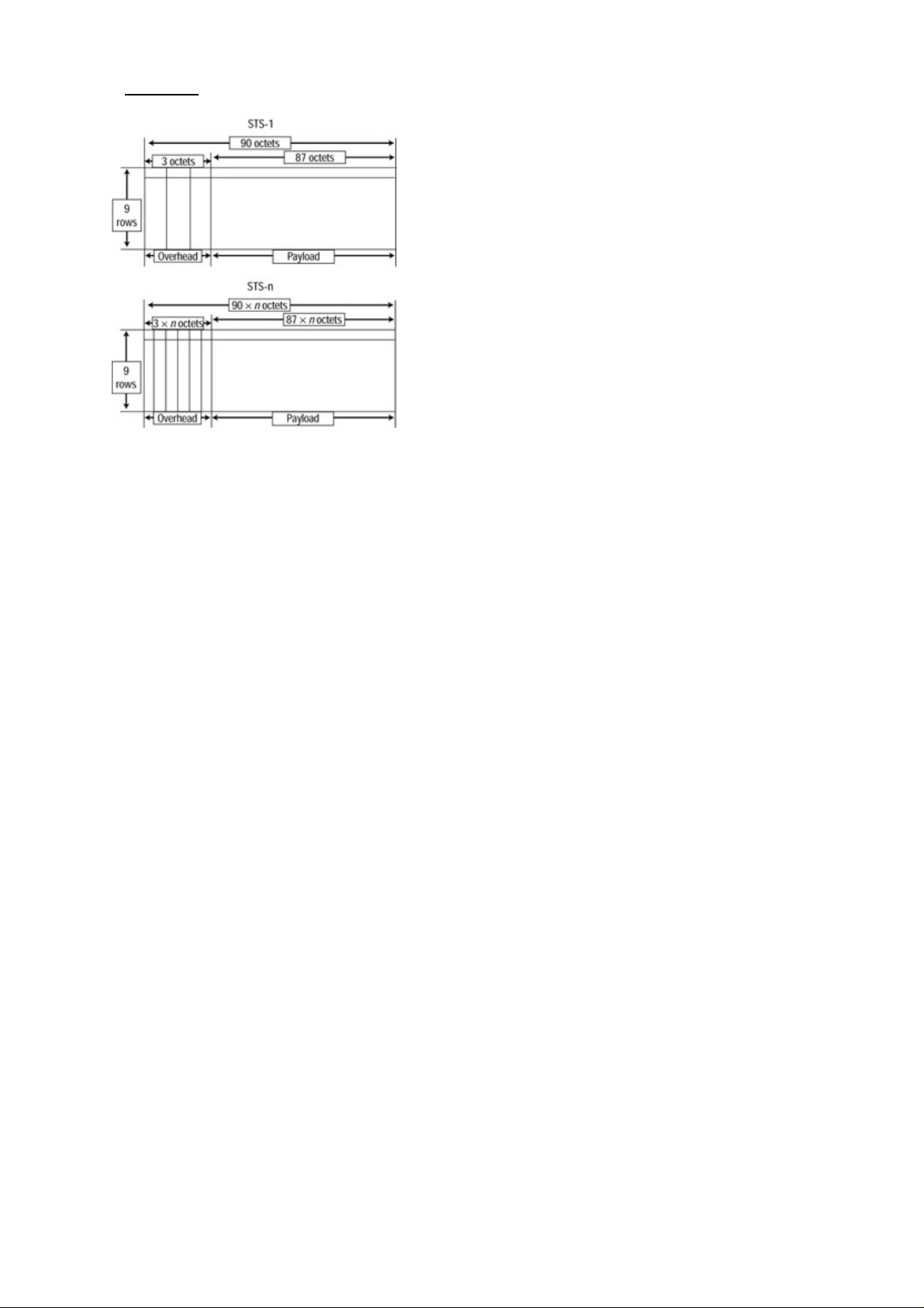
STS−n is an interleaving of multiple (n) STS−1s. The size of the payload and the overhead are multiplied by
n. Figure 3.4 displays an STS diagram.
Figure 3.4: The STS−1 framing and STS−n framing. The overhead and payload are proportionate to the n
value, with the STS−1 frame as the base.
You may wonder why we’re talking about synchronous transmission when we said it is only used over short
distances. Where did the asynchronous transmission go? Well, the asynchronous traffic is encapsulated in the
STS payload. The asynchronous serial transmission eliminates the need for the synchronization of the end
transmitting equipment. In SONET, most WAN links are a point−to−point connection utilizing light as the
signaling source. The time required for the signal to travel the link does not distort the synchronization. The
OC−n signal itself is used for the synchronization between equipment. This combination of asynchronous and
synchronous serial transmission enables signals to reach across long distances with minimal overhead.
Cisco WAN Switches
The current Cisco WAN product line consists of the following switches:
MGX 8200 series•
IGX 8400 series•
BPX 8600 series wide−area switches•
MGX 8800 series wide−area edge switches•
MGX 8200 Series
The Cisco MGX 8200 series is designed to function as a WAN edge device. It combines multiple narrowband
transmissions into a single broadband trunk. It functions as a standalone unit to connect to the ATM network
or it can be used as a feeder device to other WAN switches. The series consists of the MGX 8220 Edge
Concentrator, the MGX 8240 Private Line Service Gateway, and the MGX 8260 Media Gateway.
The MGX 8220 Edge Concentrator has 16 slots with the capability for full redundancy. It accepts two classes
of modules: common control cards and function modules. Six slots are reserved for common control cards,
and 10 slots are reserved for function modules. The common control card consists of an AXIS Shelf
Controller (ASC) card, a Service Resource Module (SRM) card, and a service trunk card. Each card can use
either of two specific slots. When both slots are occupied, one of them acts as a hot standby. The ASC card
provides a user interface for the overall control, configuration, and management of the unit. The SRM controls
the flow of traffic from the trunk card to various function modules. The service trunk module is the only
broadband interface (OC−3 or T3) that transports the aggregated traffic to the ATM network. The function
modules are narrowband interface cards. The narrowband transmission can be T1, high−speed Frame Relay,
57
Page 74

ATM frame user−network interface (UNI), or System Network Architecture (SNA).
The MGX 8240 Private Line Service Gateway is designed to terminate private lease lines (T1, T3, or DS0). It
has 16 slots with 1 reserved for a redundant control card. It can support up to 1,260 channelized T1s. It is
designed for large Internet service providers (ISPs) to aggregate dial−in traffic, which is delivered by the local
central office’s Class 4 or Class 5 switch in a T1 or T3 interface. The combined traffic is delivered to the
broadband network via OC−3 trunk ports.
The MGX 8260 Media Gateway is a high−density, carrier−class gateway for voice and data traffic. It is
designed to move data traffic from voice line to packet network. It can also function as a Voice over IP (VoIP)
gateway. The chassis has 14 slots for interface modules and 2 slots for switch control cards. A fully
configured system has over 16,000 VoIP ports. The gateway has advanced voice features: echo cancellation,
dynamic de−jitter, Voice Activity Detection (VAD), Comfort Noise Generation (CNG), and announcement
play−outs (AU or WAV files). It can connect to the broadband network via six broadband service cards
(BSCs). Each BSC has six channelized DS3 interfaces.
IGX 8400 Series
The IGX is the successor to the IPX switch. It was the first commercial implementation of Cisco’s fastpacket
cell technology. It employs fixed−length cells for switching all types of traffic (voice, data, and Frame Relay).
The IGX adds a higher bus capacity, a higher access rate, and ATM. The series has three models:
IGX 8410—Has 8 slots with 2 reserved for redundant processor modules.•
IGX 8420—Has 16 slots with 2 reserved for redundant processor modules.•
IGX 8430—Has 32 slots with 2 reserved for redundant processor modules.•
One of the major differences between the MGX and IGX series is the trunk ports. The IGX can use any of the
module interfaces as the trunk connection to an edge device. The speed ranges from 256Kbps to OC−3. The
IGX also has advanced switching and routing capabilities: It uses a distributed intelligence algorithm to route
new connections and react to failures in transmission media. It provides full control of network resources with
multiple classes of service, and it can provide different QoS to individual applications.
Each of the service modules has a large buffer. The ATM module can buffer 128,000 cells, and the Frame
Relay can buffer 100,000 frames. The buffer can be allocated by QoS to each virtual circuit based on the
amount of traffic and service−level agreements.
The IGX is marketed to the enterprise as its core WAN switch. The ability of the IGX to switch and route
between multiple trunks enables it to connect a large number of sites. The capability to handle voice, data, fax,
and video traffic in a single network minimizes the overall expense for the enterprise.
IGX is also marketed to carriers in situations where there is not enough traffic to justify purchasing a
high−end WAN switch (such as a BPX). It enables the carrier to gradually increase the capacity of the
network.
Note Another Cisco product that belongs with the IGX (but that is not considered a WAN device) is
the MC3810 Multiservice Concentrator. It has the same switch technology as the IGX series. It
utilizes the Cisco Internetwork Operating System (IOS) for configuration commands. The
MC3810 can combine data, voice, and video traffic into a channelized ATM T1/E1.
BPX 8600 Series Wide−Area Switches
The BPX 8600 series, first introduced in 1993, is the flagship of the Cisco WAN switch line. It is designed to
function as the core of the WAN ATM network. The series has three models: BPX 8620, BPX 8650, and BPX
8680. All three models have the same chassis type with 15 slots; 2 slots are reserved for redundant control and
switch modules, 1 slot is reserved for an alarm status monitor module, and 12 slots are reserved for interface
modules.
58
Page 75

The BPX 8620 is a pure ATM broadband switch. It has a nonblocking 9.6Gbps architecture. The interface
modules range from T3 to OC−12. Each trunk port can buffer up to 32,000 cells. The OC−12 interface
module has two OC−12 ports. The OC−3 interface module has eight OC−3 ports. The BPX is commonly used
in conjunction with multiple MGX switches. The MGX concentrator terminates narrowband traffic to an
OC−3 trunk to the BPX 8620, which aggregates it to multiple OC−12s to the WAN ATM network.
With the popularity and the increase of TCP/IP traffic on the WAN, Cisco introduced the BPX 8650 to
enhance the functionality of the BPX series. The BPX 8650 adds a Label Switch Controller (LSC) to the BPX
8620. The LSC provides Layer 3 functionality to the ATM traffic. It enables the use of Multiprotocol Label
Switching (MPLS) and virtual private networks (VPNs). Currently, the LSC is a Cisco 7200 series router with
an ATM interface. The plan is to have native LSC modules for the BPX series (similar to a Route Switch
Module [RSM] for the Catalyst LAN switches). The BPX 8650 also introduced a new control and switch
module to increase the throughput to 19.2Gbps.
The BPX 8680 is the newest member of the series. This addition is a combination of the BPX 8650 and the
MGX 8850 edge switch. It incorporates a modular design. Up to 16 MGX 8850s can be added to the BPX
8680 as feeders to a BPX 8620, creating a port density of up to 16,000 DS1s (T1). The 16 MGX 8850s and
the BPX 8680 are managed as a single node; this design enables the use of MPLS for all the ports on every
connected MGX. A service provider can install a BPX 8680 with a single MGX 8850 connected at a new
location. Then, when the traffic warrants, the service provider can simply add MGX 8850s to the cabinet.
MGX 8800 Series Wide−Area Edge Switches
The MGX 8800 series is the newest line of WAN switches. It is designed as an edge device to connect
narrowband traffic to broadband. The capability of the switch enables you to move it closer to the core. It has
the greatest flexibility of all the WAN switches. It has 32 single−height (16 double−height) module slots. Two
of the double−height slots are reserved for redundant processor switch modules, 4 single−height slots are
reserved for optional value−added service resource modules, and 24 single−height slots are reserved for
interface modules.
The throughput can scale from 1.2Gbps to 45Gbps. A route processor module can be added for Layer 3
functionality (a Cisco 7200 series router in a single double−height module). The network interfaces range
from Ethernet, Fiber Distributed Data Interface (FDDI), and channelized T1 to OC−48c. A Voice
Interworking Service Module (VISM) can be added to terminate T1/E1 circuits. Each module has 8 T1/E1
interfaces, and up to 24 modules can be added to the chassis (a total of 4,608 voice calls for T1 and 6,144
voice calls for E1). The VISM provides toll−quality voice services. All the packetization and processing are
handled by the module. It supports echo canceling, voice compression, silence suppression, VoIP/VoATM,
auto fax/modem tone detection, and more.
WAN Switch Hardware Overview
Cisco WAN switches have a wide range of capabilities and features. Physically, they share many common
characteristics. All the WAN switches are designed to have a minimum 99.999 percent service availability
when configured properly—that is, 5.256 minutes of downtime in 1 year of continuous operation. Each
component can have a hot standby to act as a failsafe. All the components are hot swappable, and all the
chassis have redundant power feeds.
For ease of replacement and upgrades, all the modules consist of a front card and a back card. The front card
contains the intelligent part of the card set: the processor, memory, storage, control button, and other
components. The back card contains the Physical layer component. If there is no backplane for the set, a blank
faceplate is used. This system enables the quick replacement/upgrade of the front card without distributing the
physical connections. The front card and back card are connected to a system bus backplane when inserted.
59
Page 76

The system bus backplane contains multiple buses for connecting the modules. It has no active component.
Different buses provide power to the modules, transfer of data, timing control, system commands, and other
functionality.
Cisco WAN Switch Network Topologies
We’ve talked about the transmission media, the signal, and the equipment. Let’s put it all together. Cisco
classifies WAN topologies into three designs: flat, tiered, and structured.
In a flat design, the WAN switches are connected in a fully meshed network. All the nodes are aware of one
another. Each node can send traffic to another node with a direct connection. This design is only suitable in a
small WAN network (private enterprise network). Figure 3.5 displays a typical flat WAN network.
Figure 3.5: : A flat WAN network.
In a tiered network, the core WAN switches have to route traffic for other nodes. This design utilizes edge
switches as feeders to the network. The feeders aggregate multiple narrowband transmissions into broadband
trunk connections to the core switches. The edge switches can be right next to the core switch, or they can be
miles apart. The IGX series and the MGX 8800 series can be configured as core switches or feeders. The BPX
can only be configured as a core switch, whereas the MGX 8200 series can only be a feeder node. Figure 3.6
displays how a tiered network combines different equipment.
Figure 3.6: A tiered WAN network.
The structured network design is a combination of flat networks and tiered networks. Each of these networks
is considered a domain. All domains have a unique number. Each domain is attached to others through
switches called junction nodes that are responsible for routing across domains. Switches other than junction
60
Page 77

nodes in the domain have limited contact with switches outside the domain. You will rarely see this design
today, because the current switching software no longer supports it.
Network Management
In managing a wide area network, you have to understand the basic network management technology common
to both LANs and WANs. You must understand IP addressing, Simple Network Management Protocol
(SNMP), out−of−band management/in−band management, Management Information Bases (MIBs), network
management tools, configuration of systems, and so on. Let’s look at some WAN specifics.
The CLI
Everyone who has worked with Cisco equipment is familiar with the Command Line Interface (CLI). The
WAN interface is very different from the interfaces in other Cisco equipment. To gain access to the CLI, you
will have to use the serial port on the control module, the Ethernet connection, or a virtual terminal. Figure 3.7
displays an initial login screen. You are provided with this display when you first Telnet into the equipment.
Figure 3.7: An initial login screen.
The login screen is divided into three parts: system information, display, and input. The system information
appears at the top of the screen. It contains the name of the unit, method of accessing the CLI, current user ID
and privilege level, chassis model, system software version, and date/time/time zone. The display portion
shows the result and the last command given. The input portion has a prompt for your next command.
You can enter commands on the CLI in three ways:
Via a menu—Pressing the Esc key opens a menu; you highlight a command using the arrow keys and
•
press Enter to issue the command.
In response to prompts—A prompt will request the required parameters. Using the prompt method,
•
you enter the desired command, and the switch asks you for all the required parameters.
Using direct entry—Direct entry is the only way to issue optional parameters in the CLI; all the
•
parameters must follow the command in exact order, separated by spaces.
Every command falls into a privilege level. The levels are superuser, service, StrataCom, and 1 to 6. A level is
assigned when the user account is created. The user can issue commands only at his or her level or lower. The
superuser, service, and StrataCom levels rank above level 1 (the highest numerical level).
WAN Manager
The Cisco WAN Manager software manages an entire WAN infrastructure. It operates on Sun Solaris and
IBM AIX systems. The software’s components are as follows:
Topology Management—Provides an automatically generated topology map. The map can be
•
formatted as a standalone or for HP Open View, CiscoWorks, or IBM NetView. A multicolor map
can be generated that’s updated in real time. It can provide the network manager with a global view of
61
Page 78

the network while highlighting any local problems.
Connection Management—Provides a graphic interface to configure WAN switches. It provides
•
templates to minimize the work in setting up many connections. All interface modules are supported,
including VoIP/VoATM setups.
Performance and Accounting Data Management—Controls the collection of SNMP information from
•
the network. The statistics collected are stored in an Informix database. Reports can be generated by
the built−in report generator or by SQL.
Element Management—Provides a reactive response to events on the network. It can forward
•
information to HP Open View and IBM NetView (CiscoWorks is an integrated part of Cisco WAN
Manager). External action is also supported; a page or an email can be sent when a specific event
happens on the network.
Accessing and Setting Up IGX and BPX Switches
The setup and the interface of IGX and BPX switches are very similar. During initial setup, you will have to
attach a terminal or computer with a terminal program to the DB25 control port or DB25 auxiliary port with a
straight−through EIA/TIA−232 cable. The terminal must be set at 9600bps, with no parity, eight data bits, one
stop bit, and no flow control (hardware or software).
Adding New Users
Anyone can add a user account. The new user must have a lower privilege level than the user account’s
creator. User accounts and passwords are global in the network—when you create a user account on one node,
that user account can access any other node in the network.
To add a user, use the adduser command. This command has a privilege level of 5. Figure 3.8 displays a
login screen.
Figure 3.8: The adduser command.
Displaying a User’s Password
You can display the password of a current user and any user with a lower privilege level than the current user
by using the dsppwd command, which has a privilege level of 6. The passwords will be displayed for 10
seconds.
Changing a User’s Password
To change your password, use the cnfpwd command; it has a privilege level of 6. When you enter “cnfpwd”
on the command line, the system will prompt you for your current password. You must enter the new
password twice for the system to save it. The password must be between 6 and 15 characters long, and it is
case sensitive.
You cannot change the password of any other user. To change another user’s password, you must log in as
that user. You can use the dsppwd command to view another user’s password and log in as that user.
62
Page 79

Using the History Command
You can display a list of the previous 12 commands by pressing the period (.) key; this command has a
privilege level of 6. You can select which command to repeat by entering a number from 1 through 12.
(Entering “1” repeats the most current command, “5” repeats the command five back in the list, and so on.)
After you enter the number, the previous command is copied to the command line. You can edit the command
or parameters before issuing the command. Use the arrow keys to move along the command line, and use the
backspace key to erase the character to the left of the cursor.
Displaying a Summary of All Card Modules
The dspcds command displays a summary of all the modules. The privilege level for this command is 6. The
information is generated by the switch and does not need to be configured. The command displays the front
card’s name and revision code, the back card’s name and revision code, and the status of the card. The
revision code indicates the model, hardware revision, and firmware revision.
Displaying Detailed Information for a Card Module
To display more detailed information about the card module, use the dspcd command followed by a space and
the module number. This is a privilege level 6 command. The command provides the card serial numbers,
card features, features supported, number of connections supported, buffer size, memory size, and software
version.
Displaying the Power and Temperature of a Switch
The dsppwr command provides the status of the power supply and the cabinet temperature. The privilege
level for this command is 6. This command’s display is different on the IGX than on the BPX. The IGX
displays the power supply type and status, actual cabinet temperature, temperature alarm threshold, and
monitor status; the BPX displays the ASM status, AC power supply and status, and fan speed.
Displaying the ASM Statistics for BPX
To have the BPX’s ASM provide environment information and statistics, use the dspasm command; it has a
privilege level of 6. The statistics count displays the successful polling of the environmental conditions. The
statistics timeout displays the unsuccessful attempts.
Configuring the ASM Setting for BPX
The command cofasm is used to change the Alarm Service Monitor alarm thresholds and to configure alarm
notification. It has a privilege level of 1. When you enter “cofasm” on the command line, a list of current
settings is displayed. The command line will prompt you for the selection and setting. You can set the alarm
level for the temperature threshold, power deviation from −48, polling interval, fan threshold, power voltage,
and power failure.
Logging Out
To log out of the CLI session, use the bye command; it has a privilege level of 6. If you are using Telnet, your
session will be disconnected. On the control port or auxiliary port, you will see the logon screen.
Resetting the Switch
The clear configuration command, clrcnf, will erase the connections, trunks, circuit lines, and other network
settings. This is a fast way to clear settings if you’re moving the switch to another location. The switch name,
IP address, user, and other function settings are maintained. To change all the settings back to their factory
defaults, use the clrallcnf command; this is a service−level command. You must be logged in at the superuser,
63
Page 80

service, or StrataCom level.
Displaying Other Switches
To display a list of known switches, use the dspnds command. This command is privilege level 6. You should
see only the one switch on the display until connectivity is established with other switches. You can add the
optional parameter +n to display the switch number.
Setting the Switch Name
You can configure a name by which the switch will be known in the network using the command cnfname
followed by the hostname. The switch name will be distributed automatically on the network. The name is
case sensitive and must be unique on the network. This is a level 1 command.
Setting the Time Zone
The command cnftmzn will set the local time zone for the switch. This command ensures that the switch has
the correct local time. The time zone is identified by an abbreviation after the command (PST, EST, or GMT).
You can also set the time zone to an offset from GMT (for example, g−8). This is a privilege level 1
command.
Configuring the Time and Date
The cnfdate command has network−wide effects; the new time and date are automatically distributed to other
switches on the network. It has a privilege level of 1. To set the time and date, use cnfdate followed by the
year, month, day, hour, minute, and second. The format of the time must use a 24−hour clock. The switch will
prompt you for confirmation before executing the command.
Configuring the Control and Auxiliary Ports
The command cnfterm sets the transmission characteristics of the control port and auxiliary port. You can set
the baud rate, parity, data bits, stop bits, and flow control. You cannot change just one parameter—you must
enter all the parameters after the command separated by spaces. This is a privilege level 6 command.
Modifying the Functions of the Control and Auxiliary Ports
The command cnftermfunc is used to modify the control port and auxiliary port. You can modify the control
port’s terminal emulation or disable switch−initiated transmission. On the auxiliary port, you can set the
printer type, autodial of the modem, and terminal emulation. This is a privilege level 0 command, equivalent
to the superuser and service account.
Configuring the Printing Function
You can print log messages and error messages on a printer. The printer can be directly connected on the
auxiliary port or connected to another switch’s auxiliary port on the network. To change the setting, use the
command cnfprt. The parameter can specify no printing, local printing, or remote printing. For remote
printing, the remote hostname must be set up on the network. This is a privilege level 6 command.
Configuring the LAN Interface
The cnflan command is used to set up the 10Mbps Ethernet port. You can set the IP address, subnet mask,
default gateway, and service port (the port used by WAN Manager). The maximum LAN transmit units and
MAC addresses will be displayed but cannot be changed. This is a privilege level 0 command, equivalent to
the superuser and service account.
64
Page 81

Accessing the MGX 8850 and 8220
The MGX 8850 has a control port, maintenance port, and LAN port. The control port is an EIA/TIA−232
Data Communications Equipment (DCE) interface. To access the control, you must use a terminal or a PC
with a terminal emulation program. The maintenance port is an EIA/TIA−232 DCE interface that utilizes
Serial Line Internet Protocol (SLIP). You must configure an IP address to the interface before it can be used.
The LAN port is a DB15 attachment unit interface (AUI). You must have the appropriate media converter.
The MGX 8220 also has the control port and maintenance port. The ports are the reverse of those on the MGX
8850—you use SLIP to connect to the control port and you use a terminal to connect to the maintenance port.
The MGX series’ CLI is different from that on the IGX and BPX. The inputs are entered one line at a time,
and the results scroll up the screen. MGX commands are case sensitive; most of the commands are lowercase,
except for Help.
Adding New Users
The adduser command will create a new user who can access the switch:
MGX.1.3.ASC.a > adduser user 2
MGX.1.3.ASC.a >
The user must have a lower privilege level than the user creating the account. The privilege level for this
command is 6.
Changing Passwords
The MGX 8220 and MGX 8850 use different commands for changing user passwords. You can change the
password of the user account you are logged in to. The password must be 6 to 15 characters. The privilege
level for this command is 6.
To change the password on an MGX 8220, use cnfpwd followed by the old password and the new password
twice:
MGX.1.3.ASC.a > cnfpwd oldpassword newpassword newpassword
The password for user is newpassword
This screen will self−destruct in ten seconds
To change the password on an MGX 8850, use the command passwd. The new password follows the
command twice:
MGX.1.3.ASC.a > passwd newpassword newpassword
Assigning a Switch Hostname
Use the command cnfname to assign a hostname for the switch:
MGX.1.3.ASC.a > cnfname MGX2
MGX2.1.3.ASC.a >
The name is case sensitive and must be unique on the network. The command has a privilege level of 1.
65
Page 82

Displaying a Summary of All Modules
The command dspcds will display the summary information of all the modules. This is a level 6 command.
The card number, card status, card type, switch name, date, time, time zone, and IP address are all displayed.
The information is displayed one screen at a time. Press the Enter key to display a second screen, and press Q
to stop the display.
Displaying Detailed Information for the Current Card
The command dspcd will display detailed information for the current card. The information displayed
includes the slot number, active state, type, serial number, hardware revision, firmware revision, line module
type, line module state, and fabrication number. The privilege level for this command is 6.
Note To switch between cards, use the command cc followed by the card number.
Changing the Time and Date
In the MGX series, changing the time and date requires two different commands. Both commands have a
privilege level of 0, equivalent to the superuser and service account. The time and date are not distributed out
to the network.
To change the switch’s time, use cnftime. The format must use a 24−hour clock:
MGX2.1.3.ASC.a > cnftime
cnftime "hh:mm:ss"
Time = hh:mm:ss
MGX2.1.3.ASC.a > cnftime 15:23:00
To change the date on the switch, use the command cnfdate followed by the date in month−first format:
MGX2.1.3.ASC.a > cnfdate
cnfdate "mm/dd/yyyy"
Date = mm/dd/yyyy
MGX2.1.3.ASC.a > cnfdate 09/24/2000
Displaying the Configuration of the Maintenance and Control Ports
The command xdsplns with the parameter −rs232 displays the port, type, status, and baud rate for both the
maintenance port and the control port.
To display the information on a specific port, use the command xdspln. One of the following parameters must
be used with this command:
−rs232—Information on the control or maintenance port•
−ds3—Information on the Broadband Network Module (BNM) DS3 line characteristics•
−plcp—Information on the BNM Physical layer convergence procedure line characteristics•
−srmds3—Information on the Single Route Explorer (SRE) DS3 line characteristics•
The parameter is followed by a number identifying the control port (1) or maintenance port (2). Both the
xdsplns and xdspln commands have a privilege level of 6.
Displaying the IP Address
The command dspifip displays the IP address, interface, netmask, and broadcast address. It will only display
the interface that is configured. This command has a privilege level of 6.
66
Page 83

Configuring the IP Interface
The command cnfifip is used to set the IP address, netmask, and broadcast address. Each parameter must be
entered one at a time. The parameters are as follows:
−if—The interface (26 for Ethernet, 28 for SLIP, or 37 for ATM)•
−ip—The IP address•
−msk—The network mask•
−bc—The broadcast address•
This command has a privilege level of 1.
Displaying the Alarm Level of the Switch
The command dspshelfalm is used to display the alarm level and current status of the temperature, power
supply, fans, and voltage. This is a level 6 command.
This command provides the following information for each alarm type: the threshold, severity, measurable
(temperature−related or not), current value, and status.
67
Page 84
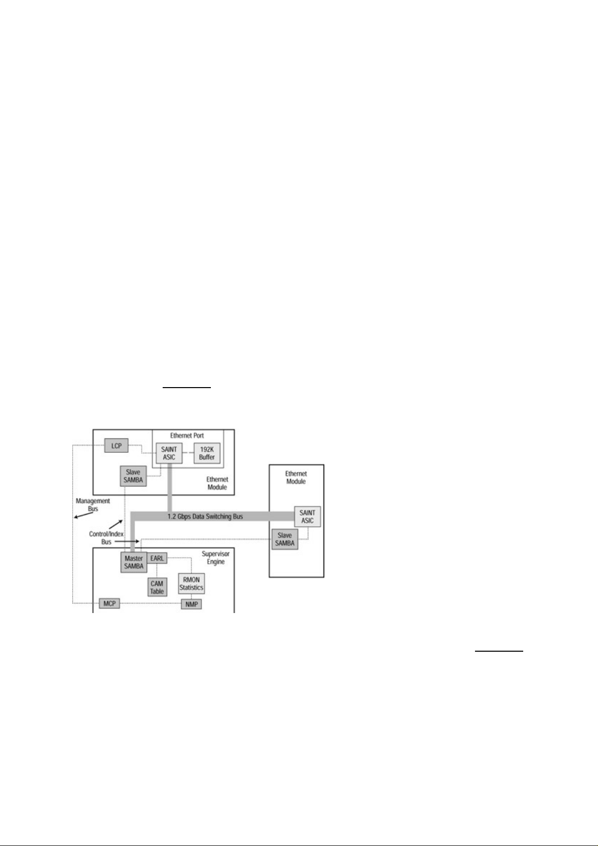
Chapter 4: LAN Switch Architectures
In Depth
Knowing the internal architectures of networking devices can be a great asset when you’re working with
Cisco switches. Knowing how the internal components work together, as well as how Application−Specific
Integrated Circuits (ASICs) and CPUs are used, can give you an advantage in determining what Cisco device
will work best at every point in the network.
The Catalyst Crescendo Architecture
When you’re looking at the architecture of the switch, ASICs are among the most important components.
ASICs are very fast and relatively inexpensive silicon chips that do one or two specific tasks faster than a
processor can perform those same functions. These chips have some advantages over a processor but lack
functions such as filtering and advanced management functions, and they have limited support for bridging
modes. ASICs make today’s switches less expensive than processor−based switches. Processor−based
switches are still available, but they are expensive and limited in the number of tasks they can take on and still
maintain reliable and acceptable limits of throughput.
The Set/Clear command−based Command Line Interface (CLI) switches (also known as Crescendo Interface
switches) found in the Cisco Catalyst 2900G, 5000, 5500, 6000, and 6500 series of switches, give the best
example of how the Broadcast and Unknown Server (BUS), ASICs, Arbiters, and logic units work inside the
switch. Let’s look at Figure 4.1, which shows a diagram of the ASICs and processors found inside a Cisco
5000 series switch. We’ll examine these components and then look at several other ASICs that are for more
specialized or earlier model Cisco Catalyst switches.
Figure 4.1: The architecture of the Cisco Catalyst 5000 series switch.
First, we need to look at the components involved: the ASICs, Catalyst processors, bus, and other units of
logic. Let’s begin by examining each of the BUSs; then we will define the ASICs shown in Figure 4.1.
BUS
Every switch must have at least two interfaces. But what fun would just two be? Today’s switches can have
hundreds of ports. The BUS connects all these interfaces—it moves frames from one interface to the other.
All these frames require an arbitration process using processors, ASICs, and logic units to make sure data
doesn’t slip out the wrong port or ports.
68
Page 85

Single BUS vs. Crossbar Matrix
A single−BUS architecture is pretty simple: One BUS connects all the ports together. This setup creates a
bandwidth problem called a blocking architecture, or what the networking industry likes to call
over−subscription. Over−subscription is characterized as a condition in which the total bandwidth of all the
ports on the switch is greater than the capacity of the switching fabric or backplane. As a result, data is held
up at the port because the tunnel−through switch is too small. Examples of Cisco switches with a single−BUS
architecture are the Cisco Catalyst 1900, 2820, 3000, and 5000 series.
A cross−bar matrix is used to solve the problems of a single BUS architecture by creating a multiple BUS
architecture in which more than one BUS services the switch ports. In this architecture, the BUS can handle
all the data the ports can possibly send—and more. It is sometimes referred to as a non−blocking architecture,
and it requires a very sophisticated arbitration scheme.
Tip The switching fabric is the “highway” the data takes from the point of entry to the port or ports from
which the data exits.
Each switch employs some kind of queuing method in order to solve blocking problems. An Ethernet
interface may receive data when the port does not have access to the BUS. In this situation, the port has a
buffer in which it stores the frame it receives until the BUS can process it. The frame uses queuing to
determine which frame will be processed next. Let’s look at the three queuing components: input queuing,
output queuing, and shared buffering.
Input Queuing
Input queuing is the simpler of the two forms of queuing. The frame is buffered into the port’s buffer until it
becomes its turn to enter the bus. When the frame enters the bus, the exit port must be free to allow the frame
to exit. If another frame is exiting the port, a condition called head−of−line blocking occurs: The frame is
dropped because it was blocked by other data.
Output Queuing
Output queuing can be used with input queuing; it allows the frame to be buffered on the outbound port if
other data is in the way. This is a way to resolve head−of−line blocking, but if a large burst of frames occurs,
head−of−line blocking still can occur. The problem of large bursts can be resolved by using shared buffering.
All the Cisco Catalyst switches (with the exception of the 1900 and 2820 series) use both input and output
queuing.
Shared Buffering
Although there is no sure way to stop head−of−line blocking, shared buffering can be used in a switch as a
safeguard. Shared buffering is a derivative of output queuing and provides each port with access to one large
buffer instead of smaller, individual buffering spaces. If a frame is placed in this buffer, the frame is extracted
from the shared memory buffer and forwarded. This method is used on the 1900 and 2820 series of Cisco
Catalyst switches.
ASICs
The ASICs shown in Figure 4.1 are used in the Catalyst 5000 series Supervisor Engine and an Ethernet
Module. Let’s take a look at each:
Encoded Address Recognition Logic (EARL) ASIC•
Encoded Address Recognition Logic Plus (EARL+) ASIC•
Synergy Advanced Interface and Network Termination (SAINT) ASIC•
69
Page 86

Synergy Advanced Multipurpose Bus Arbiter (SAMBA) ASIC•
EARL ASIC
The Encoded Address Recognition Logic (EARL) ASIC performs functions that are very similar to those of
the Content Addressable Memory (CAM) table. Switches use this CAM to make filtering and forwarding
decisions. The EARL ASIC connects directly to the data switching bus, allowing the ASIC access to all the
frames that cross the switching fabric. The switch makes forwarding decisions based on the destination Media
Access Control (MAC) address.
Note The CAM table contains the MAC address of the interfaces connected to the port and the time the switch
last read a frame from that source port and address. The CAM table receives updated information by
examining frames it receives from a segment; it then updates the table with the source MAC address
from the frame.
The EARL ASIC aids in building a table containing all the information the switch has extracted from
incoming frames. This information includes the source MAC address, the port of arrival, the virtual LAN
(VLAN) membership of the port of arrival, and the time the frame was received. This table can contain up to
128,000 entries. Entries in the table are removed after the time to live (TTL) has expired. The default TTL at
which entries are removed is 300 seconds; this time can be set from 1 to 20 minutes.
The EARL ASIC tags each frame as it arrives at the switch before the frame is buffered. This tagging includes
the source port’s identity, the VLAN, and a checksum. This tagging should not be confused with the tagging
used in trunking for Inter−Switch Link (ISL) or 802.1Q, discussed in Chapter 5. The tagging the EARL places
in the frame is removed before the frame exits the switch. The EARL ASIC’s placement is shown in Figure
4.2.
Figure 4.2: EARL ASIC placement on the Crescendo architecture.
EARL+ ASIC
The Encoded Address Recognition Logic Plus (EARL+) ASIC allows the EARL to support Token Ring line
modules. The EARL+ ASIC is an enhancement to the EARL ASIC and is used on the Supervisor Engine III
Module.
SAINT ASIC
The Synergy Advanced Interface and Network Termination (SAINT) ASIC allows a switch interface to
support both half−duplex and full−duplex Ethernet. This ASIC has a second responsibility to handle frame
encapsulation and de−encapsulation, and gathering statistics for trunked ports.
SAMBA ASIC
The Synergy Advanced Multipurpose Bus Arbiter (SAMBA) ASIC and the EARL ASIC work in tandem to
let ports access the bus, thus allowing frames to be forwarded correctly. Both the Supervisor Engine and the
installed line modules utilize this ASIC; it can support up to 13 separate line modules.
70
Page 87

This ASIC operates in either master or slave mode. In master mode, the ASIC allows ports access to the bus
based on a priority level of normal, high, or critical. In slave mode, each port must post a request to each
SAMBA ASIC, negotiate local port decisions, and arbitrate requests with the Supervisor Engine’s SAMBA
ASIC.
The Crescendo Processors
Although we have ASICs to do some of the hard work of the processors, processors still must be involved to
handle the more dynamic administrative items. They carry the intelligence behind the frame−switching
process. Inside the Crescendo Interface Internetwork Operating System (IOS) switches, the processors
connect to a bus; the bus in turn connects to other ASICs and processors inside the switch. In the following
sections, I will examine the processors listed here and their assigned functions. You will find these processors
in the Crescendo Interface Catalyst switches:
Line Module Communication Processor (LCP)•
Master Communication Processor (MCP)•
Network Management Processor (NMP)•
LCP
The Line Module Communication Processor (LCP) can be found on each line module in the switch. This
ASIC’s responsibility is to provide communications for access to the Master Communication Processor
(MCP) located on the Supervisor Engine.
The LCP automatically boots from read−only memory (ROM) and is an 8051 processor. Immediately upon
boot up, the ASIC forwards an information package called a Resetack to the MCP. Resetack includes
information regarding the switch’s boot diagnostics and module information. This information is then
forwarded from the MCP to the Network Management Processor (NMP).
MCP
The Master Communication Processor (MCP), which is sometimes called the Management Control Processor,
uses a serial management bus to communicate between the NMP on the Supervisor Engine module and the
LCP on the individual line cards located in the switch. The MCP also has a secondary job: to test and check
the configuration of the local ports, control of local ports, downloading of runtime code, and performing
continuous port diagnostics. This ASIC handles the diagnostics and obtains the usage statistics of the
on−board memory, ASICs, Local Target Logic (LTL), and Color Blocking Logic (CBL).
NMP
The Network Management Processor (NMP) is used to control the system hardware, configuration, switch
management, the Spanning−Tree Protocol (STP) (discussed in Chapter 10), and diagnostic functions.
Crescendo Logic Units
Logic units provide logic−based forwarding by VLAN, MAC address, or port assignment. The Catalyst
Crescendo Interface switches contain the following logic units:
Arbiter (ARB)•
Local Target Logic (LTL)•
Color Blocking Logic (CBL)•
Remote Network Monitoring (RMN)•
71
Page 88

ARB
The Arbiter (ARB) is located on each line module. It uses a two−tiered method of arbitration to assign
queuing priorities and control data traffic through the switch. The arbiter controls the traffic coming to and
from the line modules. In addition, a Central Bus Arbiter located on the Supervisor Engine module obtains
permission to transmit frames to the switching engine.
The Central Bus Arbiter provides special handling of high−priority frames by using a round−robin approach.
Frames with other priority levels can be set to handle support of time−sensitive traffic, such as multimedia.
LTL
The Local Target Logic (LTL) works in conjunction with the EARL ASIC to determine if a frame is switched
to one individual port or sent to multiple ports. The LTL also helps identify the port or ports on the switch to
which the frame needs to be forwarded, and it can look at the frame to determine if the frame is a unicast or a
multicast frame for broadcast forwarding. This process is handled using index values provided by the EARL
ASIC table. The LTL then uses this information to select the port or ports to forward the frame to.
CBL
The Color Block Logic (CBL) blocks data frames from entering a port that does not belong to the same
VLAN as the port of arrival. This ASIC aids STP in deciding which ports to block and which ports to place in
the learning, listening, or forwarding modes.
Other Cisco Switch Processors, Buses, ASICs, and Logic Units
In addition to the items we just discussed, other ASICs and significant components are used in the Cisco 5000
architecture as well as that of other Cisco Catalyst and Gigabit Switch Routers (GSRs).
Note ASIC is not a Cisco term. ASICs are vendor specific, and differently named ASICs can be found on
other vendor networking products.
Let’s take a closer look at the functions of these switch components:
Content Addressable Memory (CAM)•
AXIS bus•
Cisco Express Forwarding (CEF) ASIC•
Phoenix ASIC•
Line Module Communication Processor (LCP)•
Synergy Advanced Gate−Array Engine (SAGE) ASIC•
Quad Token Ring Port (QTP) ASIC•
Quad Media Access Controller (QMAC)•
CAM
The CAM table is used by a bridge to make forwarding and filtering decisions. The CAM table contains MAC
addresses with port addresses leading to the physical interfaces. It uses a specialized interface that is faster
than RAM to make forwarding and filtering decisions. The CAM table updates information by examining
frames it receives from a segment and then updating the table with the source MAC address from the frame.
AXIS Bus
The architecture of the Catalyst 3900 centers around the AXIS bus, which uses a 520Mbps switching fabric
72
Page 89

through which all switched ports communicate. The AXIS bus is a partially asynchronous time division
multiplexed bus used for switching packets between heterogeneous LAN modules.
CEF ASIC
The Cisco Express Forwarding (CEF) ASIC and Distributed Cisco Express Forwarding (dCEF) ASIC are
Cisco’s newest ASICs, found in Cisco’s lines of routers and switches. In Cisco’s switching line, you will find
this ASIC available in the 8500 GSR and 12000 GSR series.
dCEF
The dCEF ASIC is a mode that can be enabled on line cards; this mode uses interprocess communication
(IPC) to synchronize a copy of the Forwarding Information Base (FIB). This synchronization enables identical
copies of the FIB and adjacency tables to be stored on the Versatile Interface Processor (VIP), GSR, or other
line card. The line cards can then express forward between port adapters. This process relieves the Route
Switch Processor (RSP) of its involvement. The Cisco 12000 series routers have dCEF enabled by default.
This is valuable troubleshooting information, because when you view the router configuration, it does not
indicate that dCEF is enabled.
The CEF ASIC (CEFA) is a small CPU−type silicon chip that makes sure Layer 3 packets have fair access to
the switch’s internal memory. An internal CEFA search engine performs fast lookups using arbitration to
make sure lookups have metered access to the ASIC. CEF’s features include optimized scalability and
exceptional performance. Cisco has made an excellent component that fits well into large networks,
particularly those using Web−based applications that like to eat up the available bandwidth in slower
processed networks. Such applications include Voice over IP, multimedia, large graphics, and other critical
applications.
The CEFA microcontroller is local to four ports on the Catalyst 8500 GSR series line module; it uses a
round−robin approach for equal access to data traffic on each port. The CEF microprocessor also has the
responsibility to forward system messages back to the centralized CPU. These messages can include such data
as Bridge Protocol Data Units (BPDUs), routing protocol advertisements, Internet Protocol (IP) Address
Resolution Protocol (ARP) frames, Cisco Discovery Protocol (CDP) packets, and control−type messages.
CEF is a very complex ASIC that is less CPU−intensive than fast−switching route caching (discussed later in
this chapter). It allows more processing ability for other Layer 3 services such as Quality of Service (QoS)
queuing, policy networking (including access lists), and higher data encryption and decryption. As a result,
CEF offers a higher level of consistency and stability in very large networks. The FIB, which contains all the
known routes to a destination, allows the switch to eliminate the route cache maintenance and fast switching
or process switching that doesn’t scale well to large network routing changes.
The Routing Information Base (RIB) table is created first, and information from the routing table is forwarded
to the FIB. The FIB is a highly optimized routing lookup algorithm. Through the use of prefix matching of the
destination address, the FIB makes the process of looking up the destination in a large routing table occur
much more quickly than the line−by−line lookup of the RIB.
The FIB maintains a copy of the forwarding information contained in the IP routing table based on the
next−hop address. An adjacency table is then used to determine the next hop. The IP table is updated if
routing or topology changes occur. Those changes are then recorded in the FIB, and the next hop is then
recomputed by the adjacency table based on those changes. This process eliminates the need for fast or
optimum switching (discussed later in this chapter) in previous versions of the IOS.
CEF allows you to optimize the resources on your switch by using multiple paths to load−balance traffic. You
can configure per−destination or per−packet load balancing on the outbound interface of the switch:
73
Page 90

Per−destination load balancing—Enabled by default when you enable CEF. It allows multiple paths
•
to be used for load sharing. Packets destined for a given destination or source host are guaranteed to
take the same path, although multiple destinations are available.
Per−packet load balancing—Uses a round−robin approach to determine what path individual packets
•
will take over the network. Per−packet load balancing ensures balancing when multiple paths are
available to a given destination. This method allows packets for a given destination to take different
paths. However, per−packet load balancing does not work well with data such as Voice over IP and
video; these types of data packets need a guarantee that they will arrive at the destination in the same
sequence they were sent.
The Adjacency Table
The adjacency table maintains a one−to−one correspondence to the FIB. All entries in the FIB are maintained
in the adjacency table. A node is said to be adjacent if the node can be reached in one hop. CEF uses the
adjacency table to apply Layer 2 address information determined by such protocols as Address Resolution
Protocol (ARP) when the next hop must use the physical hardware address of the interface. The adjacency
table provides the Layer 2 information necessary to switch the packet to its next point destination; the table is
updated as adjacencies are discovered.
The adjacency table contains the MAC address for routers that map to Layer 2 to Layer 3 addresses. It uses
the IP ARP to populate neighbors gleaned from IP and Internetwork Packet Exchange (IPX) updates, indexed
by interface and address. For each computed path, a pointer is added for the adjacency corresponding to the
next hop. This mechanism is used for load balancing where more than one path exists to a destination.
Using host−to−route adjacencies, a few other types of adjacencies are used to expedite switching in certain
instances. Let’s look at these instances and the conditions in which other adjacencies are used:
Null adjacency—Packets destined for a Null0. The Null0 address is referred to as the bit bucket.
•
Packets sent to the bit bucket are discarded. This is an effective form of access filtering.
Glean adjacency—A node connected directly to more than one host, such as a multihomed PC. In this
•
situation, the router or switch maintains a prefix for the subnet instead of the individual host. If a
packet needs to reach a specific host, the adjacency table is gleaned for the information specific to that
node.
Punt adjacency—Packets that need to be sent to another switching layer for handling. This is done
•
when a packet needs special handling, or when the packets need to be forwarded to a higher switching
layer.
Discard adjacency—Packets that are sent to the bit bucket and whose prefix is checked. The Cisco
•
12000 GSR is the only Cisco device using this type of adjacency.
CEF Search Engine
The CEF search engine can make either Layer 2−based or Layer 3−based switching decisions. The FIB places
incoming packets into the internal memory. From there, the first 64 bytes of the frame are read. If a Layer 2
adjacency resolution needs to be made, the microcode sends the search engine the relevant source MAC
address, destination MAC address, or the Layer 3 network destination. The search engine then conducts a
lookup of the CAM table for the corresponding information. CEF uses the search engine to find the MAC
address or the longest match on the destination network address. It does this very quickly and responds with
the corresponding rewrite information; it then stores this information in the CAM table.
The CEFA now knows the port−of−exit for the packet, based either on its MAC address or on the Layer 3 IP
or IPX network numbers. The packet is now transferred across the switching fabric to its point of destination
to be sent to its next hop. The destination interface prepares the packet prior to exiting the switch. Figure 4.3
shows the CEFA components.
74
Page 91

Figure 4.3: Cisco Express Forwarding ASIC components.
Note CEF supports Ethernet, Fiber Distributed Data Interface (FDDI), Point−to−Point Protocol
(PPP), High−Level Data Link Control (HDLC), Asynchronous Transfer Mode
(ATM)/AAL5snap, ATM/AAL5mux, ATM/AAL5nlpid, and tunnels.
Phoenix ASIC
The Phoenix ASIC is another ASIC used to handle high−speed data traffic on the Supervisor Engine III. This
ASIC provides a gigabit bridge between each of the buses located on the module. The Phoenix ASIC has a
384K buffer used to handle traffic between buses located on the module. From the perspective of the EARL
and the SAMBA, the Phoenix ASIC appears as another port on the box. Figure 4.4 depicts the Phoenix ASIC.
Figure 4.4: The Phoenix ASIC used on the Supervisor Engine III.
It is important to note that some line modules do not have access to all three buses. In the case of the Catalyst
5500 13−slot chassis, slots 1 through 5 are connected to bus A, slots 1 through 9 are connected to bus B, and
slots 1 through 5 and 10 through 12 are connected to bus C. The placement of line modules in the chassis
becomes important. You will learn more about this topic in Chapter 6.
LCP
The LCP is located on each line module. It is the responsibility of the LCP to provide communications for the
MCP located on the Supervisor Engine.
SAGE ASIC
The Synergy Advanced Gate−Array Engine (SAGE) ASIC performs the same functions as the SAINT. This
ASIC also has some additional functions, such as gaining access to the token in FDDI or Token Ring
networks. Processing performed by SAGE takes place in the hardware ASICs, requires no CPU cycles, and
adds no additional latency to the switching process.
QTP ASIC
The architecture of the Catalyst 3900 is centered around the AXIS bus (discussed earlier), using the Quad
Token Ring Port (QTP) ASIC. Cisco uses the 3900 series line of switches as its primary switch dedicated to
Token Ring topology networks. This line of switches uses a 520Mbps switching fabric through which all
switched interfaces communicate. The ASIC interfaces directly with the Quad Media Access Controller
(QMAC) ASIC and provides the necessary functions for switching directly between the four Token Ring ports
75
Page 92

connected to the QMAC ASIC.
QMAC
The QMAC uses four protocol handlers to support four Token Ring physical interfaces directly connected to
the QTP ASIC. Together, these two ASICs provide support for early token release (ETR) and Token Ring
Full Duplex (FDX) concentrator and adapter modes for dedicated Token Ring.
Bridging Types
In the early 1980s, IBM developed a non−routable protocol called NetBIOS as part of its implementation
strategy. NetBIOS joined other non−routable protocols that came into wide use, such as System Network
Architecture (SNA) and Local Area Transport (LAT). IBM also developed a physical network topology called
Token Ring. With Token Ring came a bridging technology called Source Route Bridging (SRB).
The SRB algorithm for Token−Ring LAN bridging became the IEEE 802.5 Token Ring LAN specification.
SRB has various combinations, which will be discussed in more detail in the next chapter:
Source Route Bridging (SRB)•
Source Route Transparent Bridging (SRT)•
Source Route Translational Bridging (SR/TLB)•
Transparent Bridging (TB) is another bridging technology that was developed later by DEC, and which is now
used in Ethernet networks. Although it was developed for DEC, it is the primary bridging algorithm for
today’s switches and routers. It maintains a routing table, building tables composed of destination addresses.
It has the ability to switch network packets based upon a match of the destination address, such as those used
with IP, IPX, and AppleTalk.
TB tables are built differently than routing tables. Whereas routing tables rely heavily on routing protocols to
learn about foreign networks, TB tables learn the location of each MAC address by logging the port from
which the frame arrived. Thus, assuming that the network the frame arrived from is attached to the port of
entry, TB logs the information along with a maximum age or TTL. When this maximum is reached, TB
removes the entry from the table.
Let’s take a look at each bridging type.
Source Route Bridging
SRB is a method of bridging used to connect Token Ring segments. It makes all forwarding decisions based
upon data in the RIF. It cannot acquire or look up MAC addresses. Therefore, SRB frames without a
corresponding RIF are not forwarded.
With SRB, every port on the switch is assigned a ring number. The switch itself is assigned one or more
bridge numbers. SRB uses this information to build the RIF; it then searches the RIF to determine where to
forward incoming frames.
SRB frames are modified when they arrive using explorer frames. Explorer frames are typically one of two
types: All Routes Explorer (ARE) or Spanning−Tree Explorer (STE). SRB bridges copy ARE and STE
frames and modify the RIF with their own routing information.
76
Page 93

Source Route Transparent Bridging
Source Route Transparent Bridging (SRT) is a combination of SRB and TB. SRT bridges make forwarding
decisions based on either the Routing Information Field (RIF) for the destination or the MAC address in the
frame.
Some protocols attempt to establish a connection using a frame without using a RIF. These applications send
a test frame to see if the destination is on the same ring as the source. If no response is received from this test
frame, then an All Routes Explorer (ARE) test frame with a RIF is sent. If the destination receives the ARE, it
responds, and the spanning−tree path through the bridge is used.
If the network is configured with parallel full−duplex backbones, this detected path may be very undesirable.
If the spanning−tree path is used, then only one of the backbones will carry the traffic.
Source Route Translational Bridging
Source Route Translational Bridging (SR/TLB) has a Token Ring attached to at least one port of the bridge
and another media−type topology (such as FDDI or Ethernet) attached to another port. SR/TLB’s main
function is to make the two media types transparent to one another. The bridge receives the token, converts
the data to a readable format for the Ethernet segment, and then forwards the data out the Ethernet to the
receiving host address. All this takes place transparently to both hosts on the network—the Ethernet host
believes that the Token Ring host is on Ethernet, and vice versa.
Transparent Bridging
Transparent bridges get their name because they are invisible to all the network nodes for which they provide
services. Transparent bridges and switches acquire knowledge of the network by looking at the source address
of all frames coming into their interfaces. The bridge then creates a table based on the information from the
frames it received.
If a host sends a frame to a single host on another port, then if the bridge or switch has learned the port the
destination resides on and it is on the local switch, the switch forwards the frame out the destination interface.
If the bridge or switch does not know the port the destination host resides on, it will flood the frame received
out all the ports except for the port the frame was received on. Broadcasts and multicasts are also flooded in
the same way out all the ports.
Source Route Switching
Source Route Switching (SRS) was created to overcome the disadvantages of standard TB. TB does not
support source−routing information. SRS forwards frames that do not contain routing information based on
the MAC address the same way that TB does. All the rings that are source−route switched have the same ring
number, and the switch learns the MAC addresses of adapters on these rings.
SRS also learns the route descriptors. A route descriptor is a portion of a RIF that indicates a single hop. It
defines a ring number, a bridge number, and the hop closest to the switch. Future frames received from other
ports with the same next−hop route descriptor are forwarded to that port.
If you have a Token Ring switch that has reached the limitation of ring stations on the current ring, SRS is
your best choice for bridging. Unlike SRB, SRS looks at the RIF; it never makes the changes to the RIF.
Using SRS, the switch does not need to obtain the MAC addresses of the devices. This method reduces the
number of MAC addresses that the switch must learn and maintain.
77
Page 94

Switching Paths
The switch is commonly referred to in marketing terms as a Layer 2 device. If you keep thinking that way,
this section will confuse you. By definition, switching paths are logical paths that Layer 3 packets follow
when they are switched through a Layer 3 device such as a router or internal route processor. These switching
types allow the device to push packets from the incoming interface to the interface where the packet must exit
using switching paths or table lookups. By using switching paths, unnecessary table lookups can be avoided,
and the processor can be freed to do other processing.
You’re probably wondering, “Sean, this is a switching book. Why am I learning about switching paths in
Layer 3 devices?” Well, inside switches are Layer 3 devices such as the Route Switch Module (RSM),
Multilayer Switching Module (MSM), Multilayer Switch Feature Card (MSFC), and NetFlow Feature Card
(NFFC). Later in this book, I will cover trunk links, which are links that carry more than one VLAN. Doesn’t
it seem logical that if you need to have a “router on a stick,” which is an external router used for interVLAN
routing, it might help to know if the router you are using can handle the traffic for all of your VLANs? Better
yet, you should learn the internal working paths and types of switching paths through the route processor.
Let’s take a look at all the switching paths used on Layer 3 devices.
In this section, we will focus on the following switching path types and the functions of each:
Process switching•
Fast switching•
Autonomous switching•
Silicon switching•
Optimum switching•
Distributed switching•
NetFlow switching•
Process Switching
Process switching uses the processor to determine the exit port for every packet. As a packet that needs to be
forwarded arrives on an interface, it is copied to the router’s process buffer, where the router performs a
lookup based on the Layer 3 destination address and calculates the Cyclic Redundancy Check (CRC).
Subsequent packets bound for the same destination interfaces follow the same path as the first packet.
This type of switching can overload the processor. Making Layer 3 lookups the responsibility of the processor
used to determine which interface the packet should exit takes away from more essential tasks the processor
needs to handle. It is recommended that you use other types of switching whenever possible.
Fast Switching
Consider fast switching an enhancement to process switching. This switching type uses a fast switching cache
found on the route processor board. The first received packet of a data flow or session is copied to the
interface’s processor buffer. The packet is copied to the Cisco Extended Bus (CxBus) and then sent to the
switch processor. If a silicon or autonomous switching cache does not contain an entry for the destination
address, fast switching is used because no entries for the destination address are in any other more efficient
caches.
Fast switching copies the header and then sends the packet to the route processor that contains the fast
switching cache. If an entry exists in the cache, the packet is encapsulated for fast switching, sent back to the
switch processor, and then buffered on the outgoing interface processor.
Note Fast switching is used on the 2500 and the 4000 series of Cisco routers by
default.
78
Page 95

Autonomous Switching
With autonomous switching, when a packet arrives on an interface, it is forwarded to the interface processor.
The interface processor checks the silicon−switching cache; if the destination address is not contained in that
cache, the autonomous cache is checked. The packet is encapsulated for autonomous switching and sent back
to the interface processor. The header is not sent to the route processor with this type of switching.
Note Autonomous switching is available only on AGS+ and Cisco 7000 series routers that have high−speed
controller interface cards.
Silicon Switching
Silicon−switched packets use a silicon−switching cache on the Silicon Switching Engine (SSE) found on the
Silicon Switch Processor (SSP). This is a dedicated switch processor used to offload the switching process
from the route processor. Packets must use the router’s backplane to get to and from the SSP.
Note Silicon switching is used only on the Cisco 7000 series router with an
SSP.
Optimum Switching
Optimum switching is similar to all the other switching methods in many ways. As the first packet for a flow
arrives on an interface, it is compared to the optimum switching cache, appended, and sent to the destination
exit interface. Other packets associated with the same session then follow the same path. Just as with process
switching, all the processing is carried out on the interface processor.
Unlike process switching, optimum switching is faster than both fast switching or NetFlow switching when
the route processor is not using policy networking such as access lists. Optimum switching is used on
higher−end route processors as a replacement for fast switching.
Distributed Switching
Distributed switching is used on the VIP cards, which use a very efficient switching processor. Processing is
done right on the VIP card’s processor, which maintains a copy of the router’s own route cache. This is
another switching type in which the route processor is never copied with the packet header. All the processing
is off−loaded to the VIP card’s processor. The router or internal route processor’s efficiency is dramatically
increased with a VIP card added.
NetFlow Switching
NetFlow switching is usually thought of as utilizing the NetFlow Feature Card (NFFC) or NFFC II inside the
Catalyst 5000 or 6000 family of switches. These switches use the NFFCs to let a router or internal route
processor make a routing decision based on the first packet of a flow. The NFFCs then determine the
forwarding interface decision made by the router or internal route processor and send all subsequent packets
in the same data flow to that same interface. This method offloads work that the router used to do on to the
switch’s NFFC card.
However, NetFlow switching is not just a switching type; it can be used as an administrative tool to gather
statistics in an ATM−, LAN−, and VLAN−implemented network. This type of switching actually creates
some added processing for the router or an internal route processor by collecting data for use with circuit
accounting and application−utilization information. NetFlow switching packets are processed using either the
fast or optimum switching methods, and all the information obtained by this switching type is stored in the
NetFlow switching cache; this cache includes the destination address, source address, protocol, source port,
destination port, and router’s active interfaces. This data can be sent to a network management station for
analysis.
79
Page 96

The first packet that’s copied to the NetFlow cache contains all security and routing information. If policy
networking (such as an access list) is applied to an interface, the first packet is matched to the list criteria. If
there is a match, the cache is flagged so that any other packets arriving with the flow can be switched without
being compared to the list.
Note NetFlow switching can be configured on most 7000 series router interfaces and can be used in a
switched environment. NetFlow switching can also be configured on VIP interfaces.
System Message Logging
The system message logging software can save messages to a log file or direct the messages to other devices.
By default, the switch logs normal but significant system messages to its internal buffer and sends these
messages to the system console. You can access logged system messages using the switch CLI or by saving
them to a properly configured syslog server.
Note When the switch first boots, the network is not connected until the initialization and power on
self test (POST) are completed. Therefore, messages that are sent to a syslog server are delayed
up to 90 seconds.
System logging messages are sent to console and Telnet sessions based on the default logging facility and
severity values. You can disable logging to the console or logging to a given Telnet session. When you
disable or enable logging to console sessions, the enable state is applied to all future console sessions. In
contrast, when you disable or enable logging to a Telnet session, the enable state is applied only to that
session.
Most enterprise network configurations include a Unix−based or Windows−based system log server to log all
messages from the devices in the network. This server provides a central location from which you can extract
information about all the devices in the event of a network failure or other issue. You can use several set
logging commands. Let’s take a look at those that will not be covered in the Immediate Solutions section and
what each will do:
set logging server—Specifies the IP address of one or more syslog servers. You can identify up to
•
three servers.
set logging server facility—Sets the facility levels for syslog server messages.•
set logging server severity—Sets the severity levels for syslog server messages.•
set logging server enable—Enables system message logging to configured syslog servers.•
Loading an Image on the Supervisor Engine III
Trivial File Transfer Protocol (TFTP) boot is not supported on the Supervisor Engine III or on either the
Catalyst 4000 series and the 2948G switch Supervisor Engine modules. You can use one of two commands to
load a saved image. To load copies to a TFTP server, use the following:
copy file−ld tftp
To load copies to Flash memory, use the following:
copy file−ld flash
80
Page 97

Booting the Supervisor Engine III from Flash
To boot from a Flash device, use the following command:
boot [device][image name]
Note If you do not specify an image file name, the system defaults to the first valid file in the device.
Remember that file names are case sensitive. Use the show flash command to view the Flash
files. The device can be the local Supervisor Engine’s Flash memory or a TFTP server.
Related solution: Found on page:
Using the show flash Command on a Set/Clear
Command−Based IOS
493
Setting the Boot Configuration Register
You can set the boot method for the switch manually using the boot field in the configuration register. This
command affects the configuration register bits that control the boot field, similar to the way a router does.
There are three syntaxes for the set boot config−register boot command:
rommon—This syntax forces the switch to remain in ROM Monitor mode at startup.•
bootflash—This syntax causes the switch to boot from the first image stored in Flash memory.•
system—This syntax allows the switch to boot from the image specified in the BOOT environment
•
variable.
To set the configuration register boot field, use the following command in Privileged EXEC mode:
set boot config−register boot {rommon|bootflash|system} [module number]
Here’s an example of using the command:
Seans5002> (enable) set boot config−register boot rommon 1
Configuration register is 0x140
ignore−config: enabled
console baud: 9600
boot: the ROM monitor
Seans5002> (enable)
Configuring Cisco Express Forwarding
You configure CEF in the Global Configuration mode. The following commands for configuring CEF and
dCEF are available on the Cisco 8500 and 12000 GSR series.
Enabling CEF
To enable standard CEF, use the following command:
ip cef
Disabling CEF
To disable standard CEF, use the following command:
no ip cef
81
Page 98

Enabling dCEF
To enable dCEF operation, use the following command:
ip cef distributed
Disabling dCEF
To disable dCEF operation, use the following command:
no ip cef distributed
Warning Never disable dCEF on a Cisco 12000 series.
Disabling CEF on an Individual Interface
When you enable or disable CEF or dCEF in Global Configuration mode, all supported interfaces that support
CEF or dCEF are affected. Some features on interfaces do not support CEF, such as policy routing. In that
case, you will need to disable CEF on that interface.
To disable CEF on an interface, use the following command:
no ip route−cache cef
Configuring CEF Load Balancing
To enable per−packet load balancing, use the following command:
ip load−sharing per−packet
Disabling CEF Load Balancing
To disable per−packet sharing, use the following command:
no ip load−sharing per−packet
Enabling Network Accounting for CEF
To enable network accounting for CEF on the 8500 GSR to collect the numbers of packets and bytes
forwarded to a destination, use the following command:
ip cef accounting per−prefix
Setting Network Accounting for CEF to Collect Packet Numbers
To set network accounting for CEF to collect the numbers of packets express−forwarded through a
destination, use this command:
ip cef accounting non−recursive
Viewing Network Accounting for CEF Statistics
The information collected by network accounting for CEF is collected at the route processor. Distributed CEF
information is collected by the line cards, not the route processor.
To view the statistics collected, use the following command:
82
Page 99

show ip cef
Viewing CEF Packet−Dropped Statistics
To view the number of packets dropped from each line card, use the following command:
show cef drop
Viewing Non−CEF Path Packets
To view what packets went to a path other than CEF, use the following command:
show cef not−cef−switched
Disabling Per−Destination Load Sharing
If you want to use per−packet load balancing, you need to disable per−destination load balancing. To disable
per−destination load balancing, use this command:
no ip load−sharing per−destination
Viewing the Adjacency Table on the 8500 GSR
The following command allows you to display the adjacency table on the Cisco 8500 GSR:
show adjacency
The following command will allow you to get a more detailed look at the Layer 2 information adjacencies
learned by the CEF ASIC:
show adjacency detail
Clearing the Adjacency Table on the 8500 GSR
To clear the adjacency table on a Cisco 8500 GSR, use the following command:
clear adjacency
Enabling Console Session Logging on a Set/Clear
Command−Based IOS
Different variations of the set logging command affect session logging differently. To enable session logging
for a console session, use the following command:
set logging console enable
83
Page 100

Enabling Telnet Session Logging on a Set/Clear
Command−Based IOS
To enable session logging for a Telnet session, use the following command:
set logging session enable
Disabling Console Session Logging on a Set/Clear
Command−Based IOS
To disable session logging for a console session, use the following command:
Catalyst5000> (enable) set logging console disable
System logging messages will not be sent to the console.
Catalyst5000> (enable)
Disabling Telnet Session Logging on a Set/Clear
Command−Based IOS
To disable logging for the current Telnet session, use the following command:
Catalyst5000> (enable) set logging session disable
System logging messages will not be sent to the current login session.
Catalyst5000> (enable)
Setting the System Message Severity Levels on a Set/Clear
Command−Based IOS
The severity level for each logging facility can be set using the set logging level command. Use the default
keyword to make the specified severity level the default for the specified facilities. If you do not use the
default keyword, the specified severity level applies only to the current session. The command syntax is:
set logging level [all|facility] severity [default|value]
Here’s an example of the command’s use:
Catalyst5000> (enable) set logging level all 5
All system logging facilities for this session set to
severity 5(notifications)
Catalyst5000> (enable)
Enabling the Logging Time Stamp on a Set/Clear
Command−Based Switch
84
 Loading...