

Page 1

Cisco RF Gateway 10 Hardware Installation Guide
July 25, 2012
THE SPECIFICATIONS AND INFORMATION REGARDING THE PRODUCTS IN THIS MANUAL ARE SUBJECT TO
CHANGE WITHOUT NOTICE. ALL STATEMENTS, INFORMATION, AND RECOMMENDATIONS IN THIS
MANUAL ARE BELIEVED TO BE ACCURATE BUT ARE PRESENTED WITHOUT WARRANTY OF ANY KIND,
EXPRESS OR IMPLIED. USERS MUST TAKE FULL RESPONSIBILITY FOR THEIR APPLICATION OF ANY
PRODUCTS.
Cisco Systems, Inc.
www.cisco.com
Cisco has more than 200 offices worldwide.
Addresses, phone numbers, and fax numbers
are listed on the Cisco website at
www.cisco.com/go/offices.
Text Part Number: OL-16264-04
Page 2

THE SOFTWARE LICENSE AND LIMITED WARRANTY FOR THE ACCOMPANYING PRODUCT ARE SET FORTH IN THE INFORMATION PACKET THAT
SHIPPED WITH THE PRODUCT AND ARE INCORPORATED HEREIN BY THIS REFERENCE. IF YOU ARE UNABLE TO LOCATE THE SOFTWARE LICENSE
OR LIMITED WARRANTY, CONTACT YOUR CISCO REPRESENTATIVE FOR A COPY.
The Cisco implementation of TCP header compression is an adaptation of a program developed by the University of California, Berkeley (UCB) as part of UCB’s public
domain version of the UNIX operating system. All rights reserved. Copyright © 1981, Regents of the University of California.
NOTWITHSTANDING ANY OTHER WARRANTY HEREIN, ALL DOCUMENT FILES AND SOFTWARE OF THESE SUPPLIERS ARE PROVIDED “AS IS” WITH
ALL FAULTS. CISCO AND THE ABOVE-NAMED SUPPLIERS DISCLAIM ALL WARRANTIES, EXPRESSED OR IMPLIED, INCLUDING, WITHOUT
LIMITATION, THOSE OF MERCHANTABILITY, FITNESS FOR A PARTICULAR PURPOSE AND NONINFRINGEMENT OR ARISING FROM A COURSE OF
DEALING, USAGE, OR TRADE PRACTICE.
IN NO EVENT SHALL CISCO OR ITS SUPPLIERS BE LIABLE FOR ANY INDIRECT, SPECIAL, CONSEQUENTIAL, OR INCIDENTAL DAMAGES, INCLUDING,
WITHOUT LIMITATION, LOST PROFITS OR LOSS OR DAMAGE TO DATA ARISING OUT OF THE USE OR INABILITY TO USE THIS MANUAL, EVEN IF CISCO
OR ITS SUPPLIERS HAVE BEEN ADVISED OF THE POSSIBILITY OF SUCH DAMAGES.
Cisco and the Cisco logo are trademarks or registered trademarks of Cisco and/or its affiliates in the U.S. and other countries. To view a list of Cisco trademarks, go to this
URL: www.cisco.com/go/trademarks. Third-party trademarks mentioned are the property of their respective owners. The use of the word partner does not imply a partnership
relationship between Cisco and any other company. (1110R)
Any Internet Protocol (IP) addresses and phone numbers used in this document are not intended to be actual addresses and phone numbers. Any examples, command display
output, network topology diagrams, and other figures included in the document are shown for illustrative purposes only. Any use of actual IP addresses or phone numbers in
illustrative content is unintentional and coincidental.
© 2012 Cisco Systems, Inc. All rights reserved.
Page 3

iii
CONTENTS
CHAPTER
1 Overview 1-1
Cisco RFGW-10 Features 1-2
Cisco RFGW-10 Functional Overview 1-2
Cisco RFGW-10 IOS Software 1-4
Cisco RFGW-10 Hardware 1-5
Cisco RFGW-10 System Configuration 1-5
Cisco RFGW-10 Slot Numbering 1-6
Cisco RFGW-10 Components 1-7
Fan Assembly 1-7
DC PEMs 1-10
Front Panel Display 1-14
Supervisor Engines 1-15
Cisco Supervisor Engine V-10GE 1-15
Supervisor Engine Components 1-16
Supervisor Engine LEDs 1-16
Ethernet Management Port 1-16
Supervisor Memory 1-17
Cisco RFGW 10 Supervisor Engine 7-E 1-17
Features of the Cisco RFGW-10 Supervisor Engine 7-E 1-18
Front Panel LED 1-19
Physical and Environmental Specifications 1-20
Cisco RFGW-10 DS-48 Line Card 1-20
DS-48 Line Card Components 1-21
Cisco RFGW-10 DS-384 Line Card 1-23
TCC/DTI Card 1-23
RF Switch Card 1-27
CHAPTER
OL-16264-04
Supported External AC-Input Power Shelf 1-29
Lineage AC-DC Power Shelf 1-29
2 Preparing Your Site for Installation 2-1
Safety Recommendations 2-2
Book Title
iii
Page 4

Contents
REVIEW DRAFT—CISCO CONFIDENTIAL
Compliance Requirements 2-3
NEBS Level 3 Compliance 2-3
Cautions and Regulatory Compliance Statements for NEBS 2-3
Standard Warning Statements 2-4
General Safety Warnings 2-4
Site Planning 2-7
General Precautions 2-7
Site Selection Guidelines 2-7
Site Environmental Requirements 2-8
Physical Characteristics 2-8
Floor Loading Considerations 2-9
Site Power Guidelines 2-9
Electrical Circuit Requirements 2-10
Site Cabling Guidelines 2-10
Asynchronous Terminal Connections 2-11
Interference Considerations 2-11
Rack-Mounting and Location Guidelines 2-12
Precautions for Rack-Mounting 2-12
Rack Selection Guidelines 2-13
Equipment Rack Guidelines 2-13
Site Planning Checklist 2-14
CHAPTER
Preventing Electrostatic Discharge Damage 2-15
Electrical Safety 2-15
Receiving a Cisco RFGW-10 UEQAM 2-17
Chassis-Lifting Guidelines 2-17
Tools and Equipment 2-19
Unpacking and Verifying Shipping Contents 2-19
Checking the Shipping Container Contents 2-20
Cisco RFGW-10 UEQAM Installation Checklist 2-21
3 Cisco RFGW-10 UEQAM Installation 3-1
Cisco RFGW-10 UEQAM Description 3-1
Front View 3-2
Rear View 3-3
Installation Methods 3-4
General Rack Installation Guidelines 3-4
Rack-Mounting a Cisco RFGW-10 UEQAM 3-5
Verifying Rack Dimensions 3-5
Book Title
iv
OL-16264-04
Page 5

REVIEW DRAFT—CISCO CONFIDENTIAL
Installing the Chassis Installation Brackets 3-6
Installing the Chassis Installation Handles 3-7
Attaching the Chassis Rack-Mount Brackets 3-9
Chassis Front Rack-Mount Brackets Installation 3-9
Chassis Mid-Mounted Rack-Mount Bracket Installation 3-10
Installing the Cisco RFGW-10 UEQAM in a Rack 3-12
Two-Post Rack Installation Mid-Mounted 3-16
Attaching a Chassis Ground Connection 3-18
Attaching the Cable-Management Bracket 3-20
Connecting Power to Cisco RFGW-10 UEQAM 3-21
Connecting DC-Input Power to Cisco RFGW-10 UEQAM 3-22
Powering On the Cisco RFGW-10 UEQAM 3-28
Connecting System Cables 3-28
Connecting the Lineage Power Shelf to the Cisco RFGW-10 3-28
Cabling the Power Shelf 3-29
Prerequisites 3-29
Required Tools and Equipment 3-29
Steps 3-29
Connecting a Single Power Shelf 3-30
Required Tools and Equipment 3-30
Steps 3-31
Connecting Dual Power Shelves 3-32
Required Tools and Equipment 3-32
Steps 3-32
Disconnecting Cables from the Power Shelf 3-34
Steps 3-34
Contents
CHAPTER
CHAPTER
OL-16264-04
4 Thermal Management 4-1
Blank Panels 4-1
Cooling Path 4-2
Fan Tray Removal 4-2
Environmental Monitoring 4-3
5 Installing and Removing FRUs 5-1
Installation and Removal of the DC PEM 5-2
Installing a DC PEM 5-3
Removing a DC PEM 5-6
Installation and Removal of the Fan Assembly 5-7
Book Title
v
Page 6

Contents
REVIEW DRAFT—CISCO CONFIDENTIAL
Removing the Fan Assembly 5-7
Installing the Fan Assembly 5-8
Verifying the Fan Assembly Installation 5-9
Installation and Removal of the Supervisor Cards 5-9
Installing the Supervisor Cards 5-10
Verifying the Status of the Supervisor Card 5-13
Removing the Supervisor Card 5-13
Installation and Removal of the RF Switch Card 5-14
Installing the RF Switch Card 5-15
Verifying the RF Switch Card Status 5-17
Removing the RF Switch Card 5-18
Installation and Removal of the TCC Cards 5-19
Installing the TCC Card 5-19
Verifying the Status of the TCC Card 5-22
Removing the TCC Card 5-22
CHAPTER
Installation and Removal of the Line Cards 5-23
Installing the DS-48 Line Card 5-23
Verifying the Status of the DS-48 Line Card 5-26
Removing the DS-48 Line Card 5-26
Installation and Removal of the SFP Modules 5-27
Installing SFP Modules 5-27
Mylar Tab SFP Modules 5-28
Actuator/Button SFP Modules 5-29
Bale Clasp SFP Modules 5-31
6 Cabling the Cisco RFGW-10 UEQAM 6-1
Part Numbers 6-5
Nominal Attenuation 6-6
Safety Information and Warnings 6-7
Electrical Equipment Guidelines 6-7
Preventing Electrostatic Discharge Damage 6-8
Installing the UCH on the Cisco RFGW-10 UEQAM RF Switch Card 6-8
Installing or Replacing the Cables in the UCH2 6-10
Installing the Cables in the UCH2 6-10
Removing Cables 6-13
Verifying the RF Switch Card Installation 6-14
Downstream RF Power Measurement Caution 6-14
Broken Lead Screws 6-15
Book Title
vi
OL-16264-04
Page 7

REVIEW DRAFT—CISCO CONFIDENTIAL
Cabling the Supervisor Engine 6-15
Features of the Supervisor Engine Front Panel 6-15
LEDs 6-15
10-Gigabit Ethernet Uplink Ports 6-16
Gigabit Ethernet SFP Uplink Ports 6-16
Ethernet Management Port 6-16
Console Port 6-16
Reset Button 6-17
Compact Flash Port 6-17
Port Cabling Specifications 6-17
Maximum Cable Distances 6-18
Attaching Module Interface Cables 6-18
SC Connector 6-19
LC Connector 6-20
Configuring Your Supervisor Engine 6-20
X2 Handling Guidelines and Installation 6-21
Installing the 10-Gigabit Ethernet X2 Transceiver 6-22
Removing the 10-Gigabit Ethernet X2 Transceiver 6-24
X2 Transceiver Maintenance Guidelines 6-24
SFP Guidelines 6-25
Fiber-Optic SFP Modules 6-25
1000BASE-T SFP Modules 6-27
CWDM SFP Modules 6-27
Cleaning the Fiber-Optic Connectors 6-28
Contents
CHAPTER
OL-16264-04
Cabling the TCC Card 6-29
Preventing Electrostatic Discharge Damage 6-29
TCC Card LED Summary 6-30
DTI Physical Connector 6-30
Cabling the Line Cards 6-31
Preventing ESD Damage 6-31
Connecting the Gigabit Ethernet Ports 6-32
Installing SFP Transceiver Modules in the Line Cards 6-32
Removing SFP Transceiver Modules 6-34
Connecting to the ASI Monitor Port (Optional) 6-36
Configuring the ASI Port for Monitoring 6-37
7 Cisco RFGW-10 UEQAM System Specifications 7-1
System Specifications 7-1
Power Requirements 7-2
Book Title
vii
Page 8

Contents
REVIEW DRAFT—CISCO CONFIDENTIAL
viii
Book Title
OL-16264-04
Page 9

Preface
This preface discusses the objectives, audience, and organization of the Cisco RF Gateway 10 Hardware
Installation Guide. The following sections are in this preface:
• Document Revision History, page 1
• Document Objectives, page 2
• Audience, page 2
• Document Organization, page 2
• Document Conventions, page 3
• Safety Warnings, page 4
• Related Documentation, page 4
• Obtaining Documentation and Submitting a Service Request, page 5
Document Revision History
The Document Revision History table below records technical changes to this document.
Document
Version Date Change Summary
OL-16264-01 January 2009 This is the first version of this document.
OL-16264-02 April 2009 Updated with the new cable assembly information.
OL-16264-03 June 2012 Updated with information about:
OL-16264-04 September, 2012 Added information about Lineage AC-DC power shelf
• Cisco RF Gateway 10 UEQAM Downstream 384
Line Card (also called Cisco RFGW-10 DS-384)
• Cisco RF Gateway 10 Supervisor Engine 7-E
OL-16264-04
Cisco RF Gateway 10 Hardware Installation Guide
1
Page 10

Document Objectives
This publication describes Cisco RF Gateway 10 (RFGW-10) Universal Edge Quadrature Amplitude
Modulation (UEQAM) installation, and replacement or upgrading of field-replaceable units (FRUs). The
purpose of this guide is to enable a safe and efficient installation of the Cisco RFGW-10 UEQAM.
Audience
This publication is primarily designed for the person responsible for installing, and maintaining the
Cisco RFGW-10 UEQAM. The users of this guide should:
• Be familiar with electronic circuitry and wiring practices.
• Have experience as electronic or electromechanical technicians.
• Have experience in installing high-end networking equipment. Certain procedures described in this
guide require a certified electrician.
Document Organization
The major sections of this installation guide are:
Section Description
Chapter 1, “Overview” This chapter provides an overview of the Cisco
RFGW-10 UEQAM.
Chapter 2, “Preparing Your Site for Installation” This chapter provides site preparation guidelines for
installing the Cisco RFGW-10 UEQAM.
Chapter 3, “Cisco RFGW-10 UEQAM Installation” This chapter describes the installation procedures of the
Cisco RFGW-10 UEQAM.
Chapter 4, “Thermal Management” This chapter describes thermal management of the Cisco
RFGW-10 UEQAM.
Chapter 5, “Installing and Removing FRUs” This chapter describes the installation and removal
procedures for the field-replaceable units (FRUs).
Chapter 6, “Cabling the Cisco RFGW-10 UEQAM” This chapter describes the cabling information for the
Cisco RFGW-10 UEQAM.
Chapter 7, “Cisco RFGW-10 UEQAM System Specifications” This chapter lists the specifications of the Cisco
RFGW-10 UEQAM.
Cisco RF Gateway 10 Hardware Installation Guide
2
OL-16264-04
Page 11

Document Conventions
This document uses the following conventions:
Convention Indication
bold font Commands and keywords and user-entered text appear in bold font.
italic font Document titles, new or emphasized terms, and arguments for which you supply
values are in italic font.
[ ] Elements in square brackets are optional.
{x | y | z } Required alternative keywords are grouped in braces and separated by
vertical bars.
[ x | y | z ] Optional alternative keywords are grouped in brackets and separated by
vertical bars.
string A nonquoted set of characters. Do not use quotation marks around the string or
the string will include the quotation marks.
courier font Terminal sessions and information the system displays appear in courier font.
< > Nonprinting characters such as passwords are in angle brackets.
[ ] Default responses to system prompts are in square brackets.
!, # An exclamation point (!) or a pound sign (#) at the beginning of a line of code
indicates a comment line.
Note Means reader take note.
Tip Means the following information will help you solve a problem.
Caution Means reader be careful. In this situation, you might perform an action that could result in equipment
damage or loss of data.
Timesaver Means the described action saves time. You can save time by performing the action described in
the paragraph.
Warnin g
Means
bodily injury.
reader be warned
. In this situation, you might perform an action that could result in
OL-16264-04
Cisco RF Gateway 10 Hardware Installation Guide
3
Page 12

Safety Warnings
Most safety warnings for the Cisco RF Gateway 10 are placed in relevant sections throughout the
document. For translated safety warnings, see the Regulatory Compliance and Safety Information for the
Cisco RF Gateway 10.
Warning Definition
Warnin g
MPORTANT SAFETY INSTRUCTIONS
This warning symbol means danger. You are in a situation that could cause bodily injury. Before
you work on any equipment, be aware of the hazards involved with electrical circuitry and be
familiar with standard practices for preventing accidents. To see translations of the warnings
that appear in this publication, refer to the translated safety warnings that accompanied this
device.
Note: SAVE THESE INSTRUCTIONS
Note: This documentation is to be used in conjunction with the specific product installation
guide that shipped with the product. Please refer to the Installation Guide, Configuration Guide,
or other enclosed additional documentation for further details.
Statement 1071
Related Documentation
Your Cisco RF Gateway 10 (RFGW-10) Universal Edge Quadrature Amplitude Modulation (UEQAM)
and the Cisco IOS software running on it contain extensive features and functionality, which are
documented in the following resources:
• All documentation related to the Cisco RF Gateway 10 is listed in the online Cisco RF Gateway 10
Documentation Roadmap.
• The Cisco RF Gateway 10 Quick Start Guide contains installation and configuration information. It
contains quick reference information about chassis or parts installation.
• The Regulatory Compliance and Safety Information for the Cisco RF Gateway 10 document
provides international agency compliance, safety, and statutory information for the Cisco RF
Gateway 10.
• Cisco IOS software documentation contains Cisco IOS software configuration information and
support. See the modular configuration and modular command reference publications in the set that
corresponds to the software release installed on your Cisco hardware.
• To check the minimum software requirements of Cisco IOS software with the hardware installed on
your router, Cisco maintains the Software Advisor tool on Cisco.com. This tool does not verify
whether modules within a system are compatible, but it does provide the minimum IOS requirements
for individual hardware modules or components.
Note Access to this tool is limited to users with Cisco.com login accounts.
Cisco RF Gateway 10 Hardware Installation Guide
4
OL-16264-04
Page 13

Obtaining Documentation and Submitting a Service Request
For information on obtaining documentation, submitting a service request, and gathering additional
information, see the monthly What’s New in Cisco Product Documentation, which also lists all new and
revised Cisco technical documentation, at:
http://www.cisco.com/en/US/docs/general/whatsnew/whatsnew.html
Subscribe to the What’s New in Cisco Product Documentation as a Really Simple Syndication (RSS) feed
and set content to be delivered directly to your desktop using a reader application. The RSS feeds are a free
service and Cisco currently supports RSS version 2.0.
OL-16264-04
Cisco RF Gateway 10 Hardware Installation Guide
5
Page 14

Cisco RF Gateway 10 Hardware Installation Guide
6
OL-16264-04
Page 15

CHAPTER
1
Overview
The Cisco RF Gateway 10 (RFGW-10) is a Carrier Class Universal Edge QAM (UEQAM) platform that
offers concurrent support for Standard and High Definition Digital Broadcast Television, Switched
Digital Video (SDV), Video on Demand (VoD), and DOCSIS/Modular CMTS services.
The Cisco RFGW-10 UEQAM is a chassis-based product that is based on open standards with superior
performance, capacity, power consumption, ease of management and scalability. All components of the
Cisco RFGW-10 UEQAM are designed for high availability including dual Supervisor and Ethernet
switching line cards, N:1 Universal Edge QAM line cards, dual Timing and Control line cards, dual load
balancing and load sharing Direct Current Power Entry Modules (DC PEMs) and integrated RF
switching modules.
The Cisco RFGW-10 is part of the Cisco Cable ecosystem, and is fully integrated and tested as part of
the Cisco Digital Broadband Delivery System (DBDS) video solution and Cisco uBR10012 DOCSIS 3.0
and Modular CMTS solution.
The Cisco RFGW-10 is a centralized switching architecture leveraged from the Cisco Catalyst 4500
Series switches. The Cisco RFGW-10 is a 13 rack unit carrier class, modular chassis designed for
providing front-to-back airflow and system level redundancy. All chassis components are hot-swappable
and redundant. The chassis supports “wire-once” cabling for RF line cards and an integrated dual-zone
RF switch matrix. The supervisor engine provides non-blocking, Layer 2 to Layer 4 switching with the
addition of wire-speed 10-Gigabit Ethernet uplinks, 136-Gbps capacity, and 102-mpps packet
throughput.
The Cisco RFGW-10 system is a UEQAM that supports both upstream and downstream RF cards over a
frequency range of 5 MHz to 1.2 GHz. The initial line card release is a UEQAM downstream card that
supports the DOCSIS (1.0/2.0/3.0), the EURODOCIS, and J-DOCSIS specifications.
Based on the Cisco IOS networking software, the Cisco RFGW-10 supports advanced switching and
routing features.
OL-16264-04
This document contains the following sections:
• Cisco RFGW-10 Features, page 1-2
• Cisco RFGW-10 Functional Overview, page 1-2
• Cisco RFGW-10 IOS Software, page 1-4
• Cisco RFGW-10 Hardware, page 1-5
• Cisco RFGW-10 Components, page 1-7
• Supported External AC-Input Power Shelf, page 1-29
Cisco RF Gateway 10 Hardware Installation Guide
1-1
Page 16

Cisco RFGW-10 Features
Cisco RFGW-10 Features
The Cisco RFGW-10 has the following features:
• 13 Rack-Unit Carrier Class Chassis
–
19-inch rack-mount capability
–
4536 watt capacity
–
Front-to-rear airflow design
–
Integrated RF switching
–
Cable-once (wire-once) coaxial connections
–
LCD front panel display
–
Greater than 100 Gbps system performance
–
System level redundancy
• Redundancy System Architecture
–
All major FRUs redundant (supervisor, line card, power supply)
Chapter 1 Overview
–
Dual zone integrated RF data path switch
–
500-ms line card failover
–
Full software and hardware High Availability support
- External Gigabit Ethernet and 10 Gigabit Ethernet redundancy
- DOCSIS Timing Interface (DTI) redundancy
–
System operation from single power supply
• Major System Components
–
2 Supervisor Card Slots (1:1 Redundant)
–
2 Timing, Communication, and Control (TCC)/DTI Card Slots (1:1 Redundant)
–
10 Universal Line Card Slots (N:1 Redundant)
–
12 RF Switch Card Slots (Dual Zone Redundancy)
–
2 DC PEM Slots (1:1 Redundant)
–
1 Fan Tray Module
Cisco RFGW-10 Functional Overview
The Cisco RFGW-10 is a Carrier Class Universal Edge QAM (UEQAM) platform that offers concurrent
support for Standard and High Definition Digital Broadcast Television, Switched Digital Video (SDV),
Video on Demand (VoD), and DOCSIS/Modular CMTS services. The Cisco RFGW-10 is an edge
modulation device that aggregates multiple High Speed Data and/or Video sources, processes and
modulates the digital MPEG content, and forwards the QAM modulated MPEG data to the subscriber
side devices (cable modems and set-top boxes).
1-2
The initial application of the Cisco RFGW-10 is primarily as a downstream data delivery system
(downstream from the Cisco RFGW-10 to the cable modem or set-top box). External data and
management sources (VoD servers, MCMTS devices, DNCS, and so on) aggregate into the system via
the Gigabit Ethernet and 10 Gigabit Ethernet interfaces on the Supervisor and the RF line cards. The
Cisco RF Gateway 10 Hardware Installation Guide
OL-16264-04
Page 17

Chapter 1 Overview
Cisco RFGW-10 Functional Overview
Cisco RFGW-10 architecture is based on a centralized Layer 2 to Layer 4 Ethernet switch fabric. All
external Ethernet interfaces, whether on the line cards or on the Supervisor front panel, terminate at the
Supervisor engine’s switch fabric. Traffic on any of the external interfaces can be routed to any card in
the chassis.
The supervisor engine receives either DEPI (DOCSIS) data or Video data (MPEG/UDP/IP) and forwards
the data to the RF line cards based on either the DEPI session content (IP/L2TP) or encapsulated video
session information (IP/UDP). All data path traffic is terminated at the line cards. The supervisor
receives data traffic, classifies the traffic, and forwards the data traffic to the line cards.
Control traffic for DOCSIS (DEPI mode), Video, and HA functionality is terminated on the Supervisor.
Local video mode (CLI, GUI, SNMP), remote video mode control plane (DNCS, GQI), and Native video
mode (GQI v2, object model) are implemented in the IOS and terminate at the Supervisor.
The Cisco RFGW-10 supports redundant, DTI source device inputs as part of the system clocking
architecture. It includes redundant DTI/TCC cards, which support DTI client functionality.
All line cards and modules are redundant. The Supervisors (RPR, SS), TCC, and DC PEMs support 1:1
redundancy. The line card slots can be enabled in either a single N+1 redundancy configuration or a dual
redundancy configuration (N+1, M+1). RF data path redundancy is enabled by the integrated RF Switch
matrix, which supports dual redundancy groups.
The following sections provide a high-level overview of the downstream data path:
1. Data packets are received by the Cisco RFGW-10 UEQAM via either the 10GE or multiple 1GE
interfaces.
2. Data packets are received by the switch fabric on the Supervisor card (all external Ethernet ports
terminate at the Supervisor Switch fabric). The supervisor forwards data traffic to the line cards
based on the session information and IP address. For data traffic, the supervisor de-encapsulates
IP/LT2P DEPI traffic and for Video, the supervisor de-encapsulates based on the IP address/UDP
range information.
3. All data path traffic terminates at the specific RF line card (chassis slots 3:12). All cards in the
system are synchronous to the DTI system clock reference.
4. For DEPI traffic, the DS line card extracts L2TP header information, parses and processes DOCSIS
packets, re-stamps data with DOCSIS time stamps, and completes the J.83 FEC processing.
5. For Video traffic, the DS line card classifies the video packets, manages intra-QAM scheduling,
PCR re-stamping, PID re-mapping, and J.83/FEC encoding.
6. The J.83 FEC encoded data is forwarded to the upconverter module, which modulates, upconverts,
and forwards data downstream in MPEG-2/MPEG-4 encoding.
OL-16264-04
Cisco RF Gateway 10 Hardware Installation Guide
1-3
Page 18

Cisco RFGW-10 IOS Software
Table 1-1 DOCSIS and EuroDOCSIS Downstream Data Rates
Chapter 1 Overview
Downstream Channel
Width, MHz
6 64 QAM (6)
8 64 QAM (6)
Modulation Scheme,
bit/symbol Baud Rate, MSym/sec Raw Bit Rate, Mb/sec
5.056
256 QAM (8)
256 QAM (8)
5.360
6.952
6.952
Cisco RFGW-10 IOS Software
The Cisco RFGW-10 UEQAM runs the Cisco IOS software, which is stored on the compact flash
memory disks that fit in the single compact flash memory slot on the front of the Supervisor Cards. The
compact flash can store a Cisco IOS image or the configuration file.
In addition to the flash memory disks, each Supervisor module contains onboard flash memory that
stores a boot loader. The loader executes following a system reset to reload and execute the Cisco IOS
software on the flash memory disks.
The Supervisor module also stores the system configuration in the onboard flash memory. The
configuration information read from the flash memory is buffered in the operational memory following
initialization, and is written to the flash memory device when the configuration is saved.
Each line card also contains an onboard flash memory that is used to store a boot loader, similar in
function to that used on the Supervisor card. However, the line card loader executes following a system
reset, line card reset, or line card insertion to reload and executes any code that must run on the line card.
Software images may also be stored on an external TFTP server. Based on the configuration, the proper
image might be downloaded from the TFTP server and executed.
30.34
42.88
41.71
55.62
Throughput (Bit Rate
- Overhead), Mb/sec
27
38
37
48
1-4
Cisco RF Gateway 10 Hardware Installation Guide
OL-16264-04
Page 19

Chapter 1 Overview
Cisco RFGW-10 Hardware
This section describes the Cisco RFGW-10 system and components.
Cisco RFGW-10 System Configuration
Figure 1-1 shows the location of the front and the rear system components for the Cisco RFGW-10
UEQAM.
Figure 1-1 Cisco RFGW-10 Chassis Components—Front and Rear View
3
Cisco RFGW-10 Hardware
4
2
1
7
5
6
1 Universal RF line card slots 5 TCC/DTI card slots
2 Supervisor card slots 6 DC PEMs
3 LCD/Push button panel 7 RF switch cards/coaxial cable termination slots
4 Fan assembly
271377
OL-16264-04
Cisco RF Gateway 10 Hardware Installation Guide
1-5
Page 20

Cisco RFGW-10 Hardware
273847
2
1
4
3
The Cisco RFGW-10 UEQAM is installed in a standard 19-inch equipment or telco rack. A rack-mount
kit ships from the Cisco factory with each router. The rack-mount kit includes the hardware needed to
mount the router in a standard 19-inch equipment rack or telco-type rack. Mounting in 23-inch
equipment rack is possible with optional third-party mounting hardware.
The components in the front include the Supervisor Cards, RF line cards, and the front panel LCD. The
components on the rear include the Fan Assembly, RF Switch cards (coaxial terminations), TCC (DTI
Clock) cards, and the power supply modules.
All components (excluding the LCD) are hot-swappable and field replaceable. A fully configured system
will operate with a single DC PEM installed; the second PEM is required for power supply redundancy
and power load sharing.
Note Proper configuration of the DC power input requires that both Input 1 and Input 2 are connected to the
external power source and the GND connections are connected to the Earth GND. Input 1 and Input 2
on the DC PEMs are not redundant power inputs. If only one of the inputs is connected to the external
power, the Cisco RFGW-10 UEQAM will not power-on correctly.
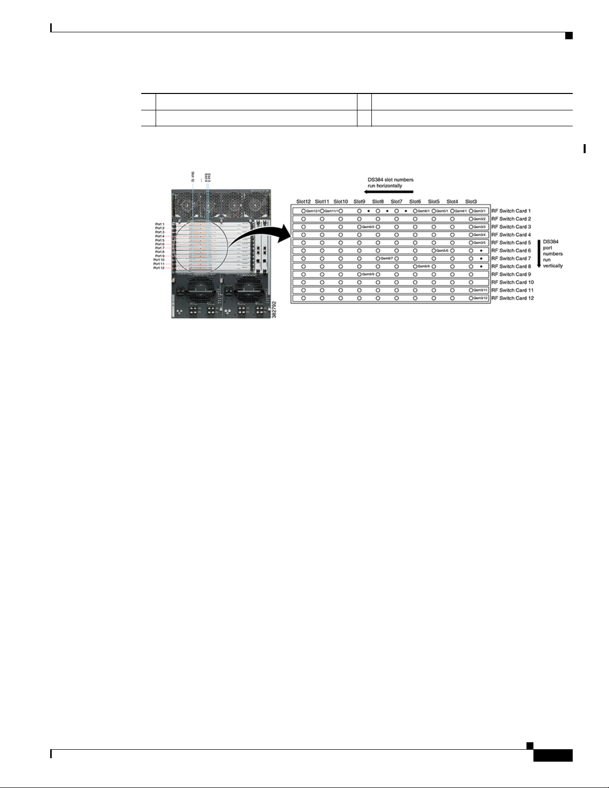
Cisco RFGW-10 Slot Numbering
Chapter 1 Overview
The figures below show the slot numbering in a Cisco RFGW-10 chassis.
Figure 1-2 Cisco RFGW-10 Slot Numbering
1-6
Cisco RF Gateway 10 Hardware Installation Guide
OL-16264-04
Page 21
Chapter 1 Overview
Cisco RFGW-10 Components
1 Supervisor Engine slots 1 and 2 3 RF Switch slots 1 through 12
2 Universal RF card slots 3 through 12 4 TCC cards slots 13 and 14
Figure 1-3 Cisco RFGW-10 Slot/Port Numbering
Cisco RFGW-10 Components
The following sections describe the components in the Cisco RFGW-10:
• Fan Assembly, page 1-7
• DC PEMs, page 1-10
• Front Panel Display, page 1-14
• Supervisor Engines, page 1-15
• Cisco RFGW 10 Supervisor Engine 7-E, page 1-17
• Cisco RFGW-10 DS-48 Line Card, page 1-20
• Cisco RFGW-10 DS-384 Line Card, page 1-23
• TCC/DTI Card, page 1-23
• RF Switch Card, page 1-27
Fan Assembly
The Cisco RFGW-10 UEQAM system uses a modular fan assembly to dissipate heat from the system
and control the temperature of the chassis system components (except the DC PEM, which contains its
own internal fan). The fan assembly is a multi-fan design that pulls ambient air from the lower front of
the chassis and exhausts air out of the rear top of the chassis. The fan assembly provides individual fan
control and failure monitoring, multiple thermistors to monitor exhaust air and a wide range of speed
control parameters based on the system and the environmental conditions. Inlet air monitoring is
communicated to the fan tray via the system software from the sensors on each of the RF line cards.
The fan tray module provides the following features:
OL-16264-04
Cisco RF Gateway 10 Hardware Installation Guide
1-7
Page 22

Cisco RFGW-10 Components
273848
• Online insertion and removal OIR support
• Failure monitoring of individual fans
• Backup temperature monitoring to control individual fan rotation per minute (RPM)
• Usage counter based on hours of operation (CLI-based)
• Front panel LED for alarm status indication
• Control and power circuit failure alarms
• On board multi-level fan speed control based on system temperature
The fan assembly draws air into the chassis and directs it across the internal system components. The
heated air exhausts out of the rear of the chassis as shown in Figure 1-4.
Figure 1-4 Cisco RFGW-10 Airflow
Chapter 1 Overview
The fan tray has four speed levels based on the operating control modes for the system. After power on,
the fan speed is set according to the Supervisor provided ambient average air temperature and the
configured speed control mode in the system configuration. The default control mode setting configures
the fans at maximum speed. The speed of the fans regulate to a slower speed when the fan controller
stabilizes to the ambient temperature and chassis temperature. After startup, it may take up to 30 seconds
for the fans to stabilize at the requested RPM.
Figure 1-5 and Figure 1-6 show the fan assembly module. The fan tray has a single LED indicator (FAN
OK) located in the center of the module. The FAN OK LED status indicators are defined in Ta ble 1 - 2:
Table 1-2 Fan Assembly LED
Cisco RF Gateway 10 Hardware Installation Guide
1-8
OL-16264-04
Page 23

Chapter 1 Overview
273443
Cisco RFGW-10 Components
LED Color Status Description
Green System OK System is functioning normally, all fans
are operating.
Amber Failure (Any Type of Failure) A single fan has failed, system triggers
alarms, but the fan assembly is still able
to cool the chassis. Repair or replace the
fan assembly as soon as possible.
Figure 1-5 Cisco RFGW-10 Fan Assembly Faceplate
Figure 1-6 Cisco RFGW-10 Fan Assembly
273444
OL-16264-04
Cisco RF Gateway 10 Hardware Installation Guide
1-9
Page 24

Cisco RFGW-10 Components
DC PEMs
Note Each DC PEM has an earth ground connection and two DC power input connections (Input 1 and Input
Chapter 1 Overview
The Cisco RFGW-10 system is powered by redundant DC PEMs. An individual PEM is capable of
providing 4536 watts of total output. The redundant modules work as a 1:1 redundancy configuration
and support OIR (hot swapping). These modules do not support current sharing as they are non-isolated
PEMs, which are diode OR'd into two separate load zones.
Each PEM includes two 60A input lines that operate between –40VDC and –60VDC input voltages.
Proper configuration and operation requires that both DC inputs are properly wired. The PEM also
includes an earth ground connection (this is not power return) for grounding the chassis.
2). Both external DC inputs (Input 1 and Input 2) must be connected as shown in Figure 1-7. Input 1 and
Input 2 are individual power inputs. Both power inputs on the PEM must be wired to external power for
the Cisco RFGW-10 UEQAM to operate properly. If both inputs are not connected to external power, the
Cisco RFGW-10 UEQAM will not power on.
DC PEM features:
• Closed frame, NEBS-compliant module design
• Front-to-back airflow (exhaust air exits out of the rear of the chassis)
• Power input range: –48VDC to –60VDC
• 4536W power capacity
• Supports OIR (hot swap)
• Supports 1:1 redundancy (system can run with a single PEM)
• CLI interface support for status and configuration
• Remote shutdown feature
• Front panel LED status and alarm indicators
Note When both the DC PEMs are installed, both need to operate with the breaker switches and the OUTPUT
OK LED on. If one PEM is not operational, it is recommended that the PEM either be removed from the
system or the power input cables be removed to limit the power supply Conductive Emissions (FCC
conductive Emission Requirements).
1-10
Cisco RF Gateway 10 Hardware Installation Guide
OL-16264-04
Page 25

Chapter 1 Overview
273170
Cisco RFGW-10 Components
Figure 1-7 shows the DC PEM faceplate.
Figure 1-7 DC PEM Faceplate
OL-16264-04
Cisco RF Gateway 10 Hardware Installation Guide
1-11
Page 26

Chapter 1 Overview
Cisco RFGW-10 Components
Table 1-3 DC PEM LEDs
LED Status Description
–48V1 Green Power input is wired correctly and
receiving proper DC power input.
Red Fault with power input. Typically this
means that the power input is wired
incorrectly with reverse polarity.
Sometimes it also indicates a failure on
the power input.
Blank External power source is not providing
power correctly (typically no power is
provided).
–48V2 Green Power input is wired correctly and
receiving proper DC power input.
Red Fault with power input. Typically this
means that the power input is wired
incorrectly with reverse polarity.
Sometimes it also indicates a failure on
the power input.
Blank External power source is not providing
power correctly (typically no power is
provided).
FAN FAIL Blank Normal Operation.
Red Alarm Condition. Fan operation is not
normal.
Fault Blank Normal Operation.
Red Alarm Condition. System Fault -
General fault indications. Power supply
is not operating normally.
CUR LIM FAIL Blank Normal Operation.
Red Alarm Condition. System is
experiencing an over current or over
power condition (exceeding 60A on
inputs).
TEMP FAIL Blank DC PEM is operating within functional
temperature range.
Red Alarm Condition. DC PEM is
experiencing an over temperature
condition.
OUTPUT OK Green All outputs from the PEM to the system
are within normal operating ranges.
Red Alarm Condition. Indicates that one of
the system voltages from the DC PEM is
out of range.
1-12
Cisco RF Gateway 10 Hardware Installation Guide
OL-16264-04
Page 27

Chapter 1 Overview
Table 1-4 DC PEM Wiring Definitions
Connector Wiring Point Description
Input 1
Input 1 RTN
Input 2
–48V • Negative DC input from external
battery source
• Input Voltage Range: –48VDC to
–60VDC (nominal), –40VDC to
–60VDC (full range)
• Wiring: #2 Gauge, #4 Gauge
• Must use Right Angle Power LUG
• Battery Return for DC input 1
• Input Voltage Range: –48VDC to
–60VDC (nominal), –40VDC to
–60VDC (full range)
• Wiring #2 Gauge, #4 Gauge
• Must Use Right Angle Power LUG
–48V • Negative DC input from external
battery source
• Input Voltage Range: –48VDC to
–60VDC (nominal), –40VDC to
–60VDC (full range)
• Wiring: #2 Gauge, #4 Gauge
Cisco RFGW-10 Components
Input 2 RTN
GND GND
• Must use Right Angle Power LUG
• Battery Return for DC input 1
• Input Voltage Range: –48VDC to
–60VDC (nominal), –40VDC to
–60VDC (full range)
• Wiring #2 Gauge, #4 Gauge
• Must Use Right Angle Power LUG
• Earth Ground Connection for PEM
and Chassis
• Wiring: #2 Gauge, #4 Gauge
• Must use Right Angle Power LUG
OL-16264-04
Cisco RF Gateway 10 Hardware Installation Guide
1-13
Page 28

Cisco RFGW-10 Components
Table 1 - 5 lists the DC power specifications.
Table 1-5 DC Power Specifications
Specifications Requirements
Power Input Range Input voltage:
Chapter 1 Overview
–48 VDC or –60 VDC (nominal), range –40 to –60 VDC
Recommended DC service: Four 60A services @ nominal
–48 VDC or –60 VDC (two 60A
services per PDU)
Required Lugs: 90° angled industry standard 2-hole compression lugs with holes on 5/8inch centers (for example, for AWG no. 4 wire: for example Panduit LCD4-14AF-L or
equivalent.
Caution The input wire gauge should be selected by certified electricians based on the
local electrical code.
Power Consumption Maximum system power is limited to 4536 watts (15,474.06 Btu/hour)
Thermal Requirements Maximum Ambient Temperature must be less than 122°F (50°C)
Power Redundancy Two DC PDUs and two DC PEMs—2N redundancy
Power Supply Ground Lug Industry standard 2-hole compression lug with holes on 5/8- inch centers (for example,
Panduit part number LCD4-14AF-L, or equivalent)
Front Panel Display
Integrated with the Cisco RFGW-10 chassis is the Front Panel Display (FPD) and Push Button Select
module. The purpose of the module is to provide real time information of the chassis configuration, IOS
images, alarm status and management, and general system auditing. The LCD is field upgradeable, but
not hot-swappable.
1-14
Figure 1-8 shows the Cisco RFGW-10 front panel display.
Figure 1-8 Cisco RFGW-10 Front Panel Display
POWER
ALARM
STATUS
The FPD is a 40 character x 4 line LCD module. The push button display and status LEDs are integrated
as part of the chassis front faceplate. The push button display provides the menu selection and a screen
scrolling mechanism to provide navigation capabilities. The FPD navigation features are not enabled in
this release of the system.
Cisco RF Gateway 10 Hardware Installation Guide
TOP
ALARM
BACK
281009
OL-16264-04
Page 29
Chapter 1 Overview
120474
STATUS LED
RESET
button
10 GE uplink
ports
Gigabit SFP
ports
Switch load
indicators
CONSOLE port
Ethernet
management port
Compact
Flash
port
Cisco RFGW-10 Components
Table 1-6 Front Panel Display LEDs
LED Color/Status Description
POWER Blank Power is not on
Green Power is on
ALARM Blank No system alarms reported
Orange System alarms are reported. Refer to the
CLI and system logs for the specific
alarms.
STATUS Green Future LED. Is Green when the system
is powered on normally.
Note The FPD features depend on the release of the Cisco IOS software running on the Cisco RFGW-10. The
initial release of the IOS software for the Cisco RFGW-10 will include the basic FPD features,
Hostname, IP Address, and IOS Version, and Customer Configured Description Field. Please refer to the
release notes for the Cisco IOS release running on the platform.
Supervisor Engines
This section describes the following supervisor engines for the Cisco RFGW-10:
• Cisco Supervisor Engine V-10GE, page 1-15
• Cisco RFGW 10 Supervisor Engine 7-E, page 1-17
Cisco Supervisor Engine V-10GE
Figure 1-9 Supervisor Engine V-10GE for the DS-48 Line Card
OL-16264-04
Note The Cisco Supervisor Engine V-10GE doe not support the Cisco RFGW-10 DS-384 line card.
Cisco RF Gateway 10 Hardware Installation Guide
1-15
Page 30

Cisco RFGW-10 Components
Supervisor Engine Components
The following connectors, LEDs, and buttons are located on the front panel of the supervisor engine:
• The STATUS LED, which indicates the operating state of the module
• Two Gigabit uplink ports
• Four SFP Gigabit uplinks ports
• Eight utilization indicator LEDs, which provide an approximation of the current traffic across the
backplane
• A console port (RJ-45)
• An Ethernet management port (RJ-45)
• A link status LED, which provides status for the management port
• The Reset button (recessed), which allows you to reset the system
• The Compact Flash port and eject button
Supervisor Engine LEDs
Chapter 1 Overview
Table 1 - 7 describes the meaning of the Supervisor Engine LEDs.
Table 1-7 Supervisor Engine LEDs
LED Status Meaning
STATUS Green All diagnostic tests passed.
Red A test failed.
Orange System boot or diagnostic test is in progress.
Off Supervisor is disabled.
UTILIZATION Green 1-100% If the switch is operational, this display indicates the current
traffic load over the backplane (as an approximate
percentage). Each LED lit green indicates approximately
12.5% of the load.
LINK Green The link is operational.
Orange The link is disabled by user.
Flashing orange The power-on self-test indicates a faulty port.
Off No signal is detected or there is a link configuration failure.
Active Green The port is active.
Off The port is not active.
Ethernet Management Port
The supervisor engine has a 10/100 BASE-T Ethernet management port. The Supervisor engine uses an
RJ-45 connector on the front panel with a link status LED.
Cisco RF Gateway 10 Hardware Installation Guide
1-16
OL-16264-04
Page 31

Chapter 1 Overview
Note To meet the electromagnetic interference (EMI) requirements, special UTP cables (with ferrites) should
be used for SUP Console and Auxiliary ports.
TCP/IP-based management services available through inband access also are provided through this port
(Telnet and SNMP). This management port also supports image download.
Note The 10/100 BASE-T Ethernet management ports are for network management only. These ports do not
support network switching.
Supervisor Memory
The Cisco RFGW-10 Supervisor provides 512-MB SODIMM SDRAM, 64-MB flash memory, and
512-KB NVRAM.
Cisco RFGW 10 Supervisor Engine 7-E
Cisco RFGW-10 Components
Starting with Cisco IOS-XE Release 3.2.0SQ, the Cisco RFGW-10 supports a new supervisor engine for
the Cisco RFGW-10 DS-384 line card.
Note The Cisco Supervisor Engine 7-E also supports the DS-48 line card.
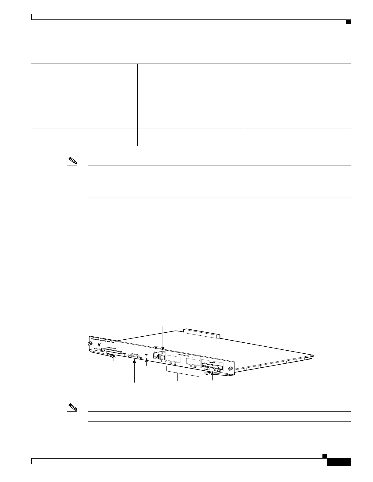
Figure 1-10 and Figure 1-11 show the faceplate and front view of the Supervisor Engine 7-E with the
major features identified.
Figure 1-10 Faceplate - Cisco RF Gateway 10 Supervisor Engine 7-E for the Cisco RFGW-10 DS-384 Line
Card
284034
OL-16264-04
Cisco RF Gateway 10 Hardware Installation Guide
1-17
Page 32

Cisco RFGW-10 Components
Figure 1-11 Cisco RFGW Supervisor Engine 7-E
1
W
S-X
45
-
S
U
P
7
-
E
S
T
A
T
U
S
1 STATUS LED 4 UTILIZATION LEDs 7 CONSOLE port (RJ-45
2 RESET switch (recessed) 5 USB ports 8 10/100/1000 MGT port (RJ-45
3 ACTIVE SUP (active su-
R
E
S
E
T
A
C
T
I
VE
S
U
P
U
T
IL
I
Z
A
T
I
O
N
2
3
4
pervisor engine) LED
Chapter 1 Overview
U
S
B
S
E
C
U
R
C
E
O
NS
D
10
I
/100/1000
G
O
L
I
T
E
AL
MG
T
1
-
2
A
C
T
I
V
1G
E
/
10G UP
L
I
N
K
S
(S
F
P
’
S
F
P+
)
3
-4
A
C
T
I
V
L
INK
1
G
5
7
6
8
E
1
0
G
9
connector)
connector)
6 SECURE DIGITAL slot 9 1G/10G UPLINKS (SFP/SFP+)
ports
279968
Features of the Cisco RFGW-10 Supervisor Engine 7-E
Table 1-8 Cisco RFGW-10 Supervisor Engine 7-E Features
Feature Description
Bandwidth per slot 48-Gbps
Memory 2-GB (upgrade to 4-GB)
Front panel features
STATUS LED The status LED indicates the current health of the supervisor engine and the current
software state. See Table 1 - 9 .
RESET switch The RESET switch is used to reset and restart the switch.
Note Use a paper clip or other small, pointed object to press the RESET switch.
ACTIVE SUP LED The active supervisor engine LED indicates whether the supervisor engine is active or
in standby mode in redundant supervisor engine configurations. See Ta b le 1 - 9 .
UTILIZATION LEDs Eight LEDs indicate (as an approximate percentage) the current traffic load over the
backplane. SeeTab le 1- 9 .
USB connectors Two USB 2.0 ports are provided. Port 1 operates in device mode (upstream) and port 2
in host mode (downstream). Port 1 has a standard Type B USB connector and can be
used as a USB console.Port 2 has a USB type A connector and a standard USB 2.0 device
like a flash memory device can plug into this connector.
SECURE DIGITAL slot A standard Secure Data (SD) memory card interface is provided on the front panel
1-18
Cisco RF Gateway 10 Hardware Installation Guide
OL-16264-04
Page 33

Chapter 1 Overview
Cisco RFGW-10 Components
Feature Description
CONSOLE port This is a 10/100/1000 port that uses an RJ-45 connector. The console port allows you
access the switch either locally (with a console terminal) has an RJ-45 connector. The
console port allows you to perform the following functions:
• Configure the switch from the CLI
• Monitor network statistics and errors
• Configure SNMP agent parameters
10/100/1000 MGT port The Ethernet management port is a Layer 3 host port to which you can connect a PC.
You can use the Ethernet management port instead of the console port for network management.
Note When connecting a PC to the Ethernet management port, you must assign an IP
address.
LINK LED The 10/100/1000 MGT port has a link LED associated with it. See Tab l e 1- 9 .
1G/10G UPLINKS
(SFP/SFP+) ports
Uplink port LEDs Each of the four uplink ports has two LEDs associated with it. One LED displays port
The Supervisor Engine 7-E has four 1-G or 10-G ports that use either SFP transceivers
or SFP+ transceivers.
status when a 1-GB SFP transceiver is installed in the port socket. The second LED
displays uplink port status when a 10-GB SFP+ transceiver is installed in the port socket.
See Table 1 - 9.
Front Panel LED
Table 1-9 Cisco RFGW-10 Supervisor Engine 7-E Front Panel LEDs
LED Color and Meaning
STATUS The STATUS LED indicates the status of he supervisor engine.
• Green—All diagnostic tests have passed
• Orange—System boot or a diagnostic test is in progress.
• Red—A diagnostic test failed.
• Off—The supervisor engine is disabled or is not powered up.
ACTIVE SUP Indicates whether the supervisor engine is active or standby.
• Green—Supervisor engine is active (in redundant supervisor engine
configurations)
• Off—Supervisor engine is in standby mode (in redundant supervisor
engine configurations)
UTILIZATION When the switch is operational, the eight utilization LEDs indicate the current
traffic load over the backplane as an approximate percentage value. Each LED
lit green indicates approximately 12.5 percent of load.
OL-16264-04
Cisco RF Gateway 10 Hardware Installation Guide
1-19
Page 34

Cisco RFGW-10 Components
Table 1-9 Cisco RFGW-10 Supervisor Engine 7-E Front Panel LEDs (continued)
LED Color and Meaning
MGT port Indicates the status of the 10/100/1000BASE-T Ethernet management port
• Green—The link is operational.
• Orange—The link is disabled by user.
• Flashing orange—The power-on self-test indicates a faulty port.
• Off—No signal is detected or there is a link configuration failure.
Uplink link Indicates the status of the uplink port
• Green—The link is operational.
• Orange—The link is disabled by user.
• Flashing orange—The power-on self-test indicates a faulty port.
• Off—No signal is detected or there is a link configuration failure.
Physical and Environmental Specifications
Chapter 1 Overview
Table 1-10 Cisco RFGW-10 Supervisor Engine 7-E Physical and Environmental Specifications
Item Specification
Dimensions (H x W x D) 1.75" x 14.5" x 11"
Weight 5.5 lbs
Power requirement 302 W
Environmental
Operating temperature
• Certified for operation: 32° to 104°F (0° to 40°C)
• Designed and tested for operation: 32° to 130°F (0° to
55°C)
Humidity (RH) ambient (non-condensing) 10 to 90%
Operating altitude
• Certified for operation: 0 to 6500 ft (0 to 2000 m)
• Designed and tested for operation: –200 to 10,000 ft (–60
to 3000 m)
Operating temperature
• Certified for operation: 32° to 104°F (0° to 40°C)
• Designed and tested for operation: 32° to 130°F (0° to
55°C)
Cisco RFGW-10 DS-48 Line Card
1-20
The Cisco RFGW-10 DS-48 line card is a QAM modulator and upconverter product designed to support
DOCSIS downstream data traffic (DEPI D-MPT) and video applications (VoD, SDV, and broadcast
video). The DS-48 card is similar to the traditional QAM solutions where the card receives encapsulated
data, de-packetizes/re-formats the packets, maps them to the output QAM channel, and performs QAM
Cisco RF Gateway 10 Hardware Installation Guide
OL-16264-04
Page 35

Chapter 1 Overview
Cisco RFGW-10 Components
modulation and frequency upconversion. From a high level, the DS-48 line card receives Video and
DOCSIS data encapsulated over Ethernet and outputs analog QAM data to the subscriber devices (STB,
DOCSIS modems).
As a DOCSIS engine, the DS-48 line card supports DEPI D-MPT mode (future SW releases may support
PSP mode). DEPI is based on the L2TPv3 protocol, which includes a data plane and a control plane.
DEPI data plane traffic is terminated at the line card. The Cisco RFGW-10 Supervisor terminates DEPI
control and communicates the control to each line card in the system via the chassis IPC infrastructure.
DOCSIS timing information (10.24MHz synchronous DTI clock) is received by the line card from the
system TCC cards.
As a video engine, the DS-48 terminates video data path traffic forwarded from the Supervisor Engine
(video control plane traffic is terminated and processed by the system Supervisor). The DS-48
processing path classifies video packets, performs inter QAM processing, bitrate scheduling, program
muxing/scheduling, PID remapping, PCR re-stamping, and CC re-stamping.
A critical feature for the DS-48 line card is redundancy and high availability support. The line cards are
designed to detect and react to a wide range of faults and failures and respond with sub-second failover
to a dedicated protect card.
The DS-48 line card is designed to support a wide range of line card health conditions and initiate
failover events if considered catastrophic:
• QAM/upconverter HW failure. The line card monitors both the digital and RF data integrity. The
modules also provide a comprehensive alarm structure to the system CPU, which allows constant
monitoring of the UPX.
• Environmental alarms (temperature, voltage, frequency).
• Software kernel failures.
• Software module failure.
• DTI Clock/Timing failures (both internal and external).
• SFP failures.
The DS-48 line card has 12 physical RF ports, which support up to four QAMs per port. The number of
QAM outputs is configurable on a per port basis (meaning an individual port can support 1, 2, or 4 QAMs
as well as muting of individual QAMs within a QAM group). In stacked QAM mode, the QAMs are
stacked contiguously over a 24-MHz or 32-MHz band. The line card supports a downstream channel
frequency range of 88 MHz to 870 MHz.
The front panel includes two 1xGE ports and a single DVB-ASI interface (covers all video output
streams). The front panel connectors support both copper and fiber SFP modules. The front panel GE
ports are not processed directly by the line card, these are independent of the line card and route directly
to the Supervisor switch fabric. These ports do not become out of service if the line card crashes and a
failover to the redundant card occurs.
DS-48 Line Card Components
OL-16264-04
The following connectors and LEDs are located on the front panel of the DS-48 line card:
• STATUS LED that indicates the operating state of the line card
• ALARM LED that indicates the general health of the line card
• TRAFFIC LED that indicates whether the card is a primary (working card) or a protect card
• LINK LED that indicates whether the link is operational
• DVB-ASI BNC Coax Interface
Cisco RF Gateway 10 Hardware Installation Guide
1-21
Page 36

Cisco RFGW-10 Components
• Two SFP Gigabit uplink ports
Chapter 1 Overview
1-22
Cisco RF Gateway 10 Hardware Installation Guide
OL-16264-04
Page 37

Chapter 1 Overview
273679
Cisco RFGW-10 Components
Table 1-11 DS-48 Line Card LEDs
LED Color/Status Description
STATUS Green Line card is powered correctly and has initialized correctly
Off Line card is not initialized correctly, not booted up
ALARM Blank Normal operation
Yellow Minor line card error
Red Major line card error
TRAFFIC Green Line card is active and traffic is processed by the card
Blue Slot [11:12]: Card is configured as backup card
Red Slots[3:10]: Card has failed over to protect slot
LINK Green The Link is operational
Blank The link is not operational
Figure 1-12 shows the DS-48 faceplate.
Figure 1-12 DS-48 Line Card Faceplate
Cisco RFGW-10 DS-384 Line Card
For information about the Cisco RFGW-10 DS-384 line card, see Cisco RF Gateway 10 Downstream 384
Line Card Hardware Installation Guide.
TCC/DTI Card
The Cisco RFGW-10 UEQAM supports two Timing, Communication, and Control (TCC) slots. The
TCC card acts as a secondary processor that controls the overall system clock generation and
distribution, DOCSIS timestamp synchronization, and system control of the Front Panel Display (FPD)
and the RF Switch cards.
The TCC card’s most critical function is distribution of the system clocking, in particular the DTI
interface. The TCC card is a DTI client interface. It supports dual DTI external input allowing DTI server
redundancy. Based on the DTI input information, the TCC card generates DOCSIS 10.24-MHz clock and
timestamp information to every line card in the chassis. All clocks and DOCSIS information are
redundant. When there is no external DTI clock, the TCC provides an internal DOCSIS DTI clock and
time stamp reference.
When two TCC cards are installed, they are configured as active and backup (redundant). If the TCC
card in the first slot is working at system power-up, it automatically becomes the active card and the TCC
card in the second slot becomes the backup card (typically Slot 13 boots as the primary TCC and Slot
14 as the secondary, but this is not mandatory).
OL-16264-04
Cisco RF Gateway 10 Hardware Installation Guide
1-23
Page 38

Cisco RFGW-10 Components
In terms of the overall system high availability, the TCC cards work autonomously from the centralized
control mechanisms. Redundant TCC cards monitor each other’s priority information so that when the
active card fails, the active card role is transferred to the redundant backup card without loss of data.
The following is a summary of the TCC card’s functions and features:
• Generates and distributes 10.24 MHz clock references and 32-bit timestamp references to every
• Drives the LCD module used to display the system configuration and status information
• Proxy control mechanism (via supervisor cards) for the RF Switch Cards
• Front Panel LEDs providing Status and Alarm Indicators
• Provides two RJ-45 ports supporting redundant DTI server sources
Chapter 1 Overview
cable interface line card
1-24
Cisco RF Gateway 10 Hardware Installation Guide
OL-16264-04
Page 39

Chapter 1 Overview
Cisco RFGW-10 Components
Table 1-12 TCC Card LEDs
LED Color/Status Description
POWER Green Power is being supplied to the TCC card.
Off Power off
STATUS Yellow Indicates that the CPU is in the bootup process,
self-test, or downloading code.
Green Indicates that the CPU has successfully completed
the boot, self-test, and code download process and
the TCC card is the Active card.
Blinking green Indicates that the CPU has successfully completed
the boot, self-test, and code download process.
Blinking green means the TCC card is the backup
card.
MAINTENANCE Off Indicates normal off. No maintenance action is
required.
Yellow Indicates that the maintenance operation is required,
and the TCC card can be hot-swapped.
DTI 1 ACT Yellow Indicates that the DTI server is connected, however
the DTI lock and communication is not established.
Off When DTI ACT is Off and the DTI Link is Green, it
indicates normal DTI connection.
When DTI ACT is Off and the DTI LINK is Off, it
indicates that the DTI interface is not linked with the
Server.
DTI 1 LINK Green Indicates that the DTI Client has established
connection with the server and the frequency is
locked.
Off When DTI ACT is Off and the DTI Link is Green, it
indicates normal DTI connection.
When DTI ACT is Off and the DTI LINK is Off, it
indicates that the DTI interface is not linked with the
server.
DTI 2 ACT Yellow Indicates that the DTI Server is connected, however
DTI lock and communication is not established.
Off Indicates that the DTI Server is not recognized or not
connected.
DTI 2 LINK Green Indicates that the DTI Client has established
connection with the server and the frequency is
locked.
Off Indicates that the DTI Server has not locked with the
DTI Client.
Cisco RF Gateway 10 Hardware Installation Guide
OL-16264-04
1-25
Page 40

Cisco RFGW-10 Components
281014
Note There are two LEDs for each DTI port (ACK and LINK). Only one of these can be on at a time.
The upper LED (ACK) indicates whether the RFGW-TCC is connected (linked) with the DTI server. It
does not indicated a frequency lock with the DTI server. Yellow illumination indicates a positive
communication link with the server. The lower LED (LINK) can either be green or off. When green, it
indicates that the DTI client has established connection with the server and the frequency is locked.
A typical transition of the LEDS is the ACK LED illuminates yellow (linked) after the system comes up
and when the DTI frequency is locked, the ACK LED becomes off and the LINK LED illuminates green.
Figure 1-13 and Figure 1-14 show the TCC/DTI Card.
Figure 1-13 TCC Card Faceplate
Chapter 1 Overview
1-26
Cisco RF Gateway 10 Hardware Installation Guide
OL-16264-04
Page 41

Chapter 1 Overview
281011
Figure 1-14 TCC/DTI Card
RF Switch Card
The RF Switch provides RF data path redundancy at both the line card (slot) level and the RF port level
for bi-directional DOCSIS traffic upto 1.2 GHz. Additionally, the RF Switch cards are the coaxial cable
termination point for the Cisco RFGW-10.
Functionally the RF Switch card physically switches out a failed line card (port by port) at the RF data
path level. The card is capable of supporting (two) simultaneous RF line card failures. It is designed to
support dual N+1 redundancy groups (where N is a group of RF line cards associated with a single
“protect” card).
Cisco RFGW-10 Components
273441
There are 12 RF Switch cards per chassis providing 120 RF ports for the system (Note: the chassis
MUST include all 12 RF Switch cards for proper operation). Each Switch Card supports a single Cisco
UCH2 connector header; the UCH2 supports 10 MCX coaxial connections per card. The RF Switch card
is physically separate from the RF line cards slots allowing insertion or removal of the RF line cards
without disruption of the cable plant wiring.
The RF Switch Card is the central hardware component for chassis-level HA features. The card can be
configured and controlled via the system level CLI functionality. The RF Switch card is a hardware and
firmware based module (no operating software) that can be field upgraded via the chassis CLI.
The RF Switch Card faceplate includes a single LED, which provides very high level status for power
and functionality. The LED does not indicate a line card failover.
Figure 1-15 and Figure 1-16 show the RF Switch Card.
Figure 1-15 RF Switch Card Faceplate
OL-16264-04
Cisco RF Gateway 10 Hardware Installation Guide
1-27
Page 42

Cisco RFGW-10 Components
Figure 1-16 RF Switch Card
The RF Switch Card supports the following features:
• 10 RF bi-directional RF ports per RF Switch card
Chapter 1 Overview
273442
–
System support for 12 RF Switch cards, 120 RF Ports per chassis
–
Wire once interface: Coax cables are independent of the RF card insertion and removal
• OIR (Hot Swap) and field upgradeability
• Supports SW field upgrades
• Exceeds DOCSIS DRFI compliance requirements over 5 MHz to 1.2 GHz frequency range
• No active gain in any switch path
• Support for Cisco UCH2 Dense (MCX) connector
• Upto two flexible redundancy groups, each capable of N:1
• LED to indicate RF Switch’s active or fail mode
• CLI support for configuring and monitoring the status information
Tabl e 1- 1 3 Stat u s LE D s
LED Color/Status Description
POWER Blank RF Switch is not powered or Severe
firmware corruption
Green Normal operating conditions
Blinking Green Severe error condition (possibly power
out of specification or firmware
corruption)
1-28
Cisco RF Gateway 10 Hardware Installation Guide
OL-16264-04
Page 43

Chapter 1 Overview
Supported External AC-Input Power Shelf
Supported External AC-Input Power Shelf
The AC-input power shelf converts AC power from an external AC power supply source into DC power
that is suitable for powering on the Cisco RFGW-10.
The Lineage AC-DC power shelf is supported on the Cisco RFGW-10.
Table 1 - 14 lists the Lineage power shelf specifications and the configurations supported on the
Cisco RFGW-10.
Table 1-14 Lineage Shelf Configurations Supported on Cisco RFGW-10
Component Configuration 1 Configuration 2
No. of Lineage Shelves
(Part Number J85480S1 L21)
Maximum Output Power
Rectifiers Modules
Power Output for Rectifiers
DC Power Output
AC Power Output
Operating Temperature
AC Power Cables
DC Power Cables
1
12
11 KW 16 KW
4 CP2725TEZ 8 CP2725TEZ or
2725 W (maximum) 1200 W (maximum)
–54 VDC –54 VDC
200–240 VAC 100–120 VAC
–40 C to 45 C –5 C to 45 C
240 VAC AC power—4 120 VAC AC power—8
Amphenol Y cables
CP2000AC54
2
Elmech straight cables
1. For more information on ordering the Lineage kit, visit www.arrow.com
2. The AC power cables supplied may vary with the country where the equipment is deployed.
For information on installation, power shelf safety features, safety warnings, and troubleshooting the
Lineage power shelf, see the product documentation available at http://www.lineagepower.com/.
Lineage AC-DC Power Shelf
The external Lineage AC-DC power shelf (part number J85480S1 L21) with AC module (CP2725TEZ
or CP2000AC54PE) is one-rack unit high (1.75 inch), and can be mounted on a standard 19-inch 4-post
equipment rack or telco-type rack. It is recommended that the Lineage power shelf is installed such that
the power connections face inside of the rack when viewed from the front. This allows the DC output
terminals of the external AC-input power shelf to be on the same side as the DC-input terminals of the
Cisco RFGW-10 chassis.
The Lineage AC-DC power shelf has two DC power sources, four AC-input power supply sources, and
J1 and J2 Jumper connectors. The J1 connector is used to connect a control interface cable and J2
connector is used for a shelf-to-shelf connection.
Note Jumpers must be removed prior to inserting a connector into the J1 housing.
• Black—2
• Red—2
• Black—4
• Red—4
OL-16264-04
Cisco RF Gateway 10 Hardware Installation Guide
1-29
Page 44

Supported External AC-Input Power Shelf
278055
3 4
2 2
11
Front view
Rear view
Each AC-input power supply module is automatically powered on when it is plugged into the wall
socket. (See Figure 1-17).
Figure 1-17 Lineage AC-DC Power Shelf - Front and Rear View
Chapter 1 Overview
1 DC power source terminal blocks 3 J2 connector
2 AC-input power connectors 4 J1 connector
All cable connections for AC-input power, DC-output power, and status signals are made from the rear
of the power shelf. Each AC power supply module has an individual AC facility cord attachment. All
four AC-input cords must be attached to the facility for all four AC power modules to function. The
DC-interconnect cables provide DC-output power to the DC PEM modules on the Cisco RFGW-10. (See
Figure 1-18).
Note The AC-input and DC-output power cables are supplied along with the Lineage kit. It is recommended
that you use these cables for cabling the shelf to the Cisco RFGW-10.
1-30
Cisco RF Gateway 10 Hardware Installation Guide
OL-16264-04
Page 45

Chapter 1 Overview
334294
1
1
22
Supported External AC-Input Power Shelf
Figure 1-18 Rear View of the Lineage AC-DC Power Shelf with Cables
1 DC-output power supply cables 2 AC-input power supply cables
To meet compliance standards, use the DC power cables (3 m cable supplied along with the Lineage
power shelf) while cabling the Lineage AC-DC power shelf to the Cisco RFGW-10.
For information on connecting the Lineage power shelf see, Connecting the Lineage Power Shelf to the
Cisco RFGW-10, page 3-28.
Cisco RF Gateway 10 Hardware Installation Guide
OL-16264-04
1-31
Page 46

Supported External AC-Input Power Shelf
Chapter 1 Overview
1-32
Cisco RF Gateway 10 Hardware Installation Guide
OL-16264-04
Page 47

CHAPTER
2
Preparing Your Site for Installation
Before you install the Cisco RFGW-10 UEQAM, consider:
• The power and cabling requirements that must be in place at your installation site
• The equipment required to install the router
• The environmental conditions your installation site must meet to maintain normal operation
This chapter contains important safety information you should know before working with the Cisco
RFGW-10 UEQAM and guides you through the process of preparing your site for router installation.
Note Do not unpack the system until you are ready to install it. Keep the chassis in the shipping container to
prevent accidental damage until you determine an installation site. Use the appropriate unpacking
documentation included with the system.
Warnin g
Warnin g
Warnin g
Warnin g
Read the installation instructions before connecting the system to the power source.
1004
Only trained and qualified personnel should be allowed to install, replace, or service
this equipment.
Ultimate disposal of this product should be handled according to all national laws and
regulations.
Class 1 laser product.
This chapter contains the following sections:
• Safety Recommendations, page 2-2
• Compliance Requirements, page 2-3
• Cautions and Regulatory Compliance Statements for NEBS, page 2-3
• Standard Warning Statements, page 2-4
• Site Planning, page 2-7
Statement 1030
Statement 1040
Statement 1008
Statement
OL-16264-04
Cisco RF Gateway 10 Hardware Installation Guide
2-1
Page 48

Safety Recommendations
• Preventing Electrostatic Discharge Damage, page 2-15
• Electrical Safety, page 2-15
• Receiving a Cisco RFGW-10 UEQAM, page 2-17
• Chassis-Lifting Guidelines, page 2-17
• Tools and Equipment, page 2-19
• Checking the Shipping Container Contents, page 2-20
• Cisco RFGW-10 UEQAM Installation Checklist, page 2-21
Safety Recommendations
The following guidelines will help to ensure your own safety and protect your Cisco equipment. This list
does not cover all potentially hazardous situations, so be alert.
• Cisco safety policy is that all of its routers must conform to the requirements of IEC 60950, with
appropriate national deviations, as a minimum. In addition, Cisco routers must also meet the
requirements of any other normative documents (for example, standards, technical specifications,
laws or regulations).
• Review the safety warnings listed in the Regulatory Compliance and Safety Information Guide that
accompanied your Cisco RFGW-10 UEQAM before installing, configuring, or maintaining the
router.
• Never attempt to lift an object that might be too heavy for you to lift by yourself.
Chapter 2 Preparing Your Site for Installation
• Always turn all the DC PEMs off and disconnect all power cables before opening the chassis.
• Always disconnect the power cables before installing or removing a chassis.
• Keep the chassis area clear and dust free during and after installation.
• Keep the tools and chassis components away from walk areas.
• Do not wear loose clothing, jewelry (including rings and chains), or other items that could get caught
in the chassis. Fasten your tie or scarf and sleeves.
• The Cisco RFGW-10 UEQAM operate safely when it is used in accordance with its marked
electrical ratings and product usage instructions.
2-2
Cisco RF Gateway 10 Hardware Installation Guide
OL-16264-04
Page 49

Chapter 2 Preparing Your Site for Installation
Compliance Requirements
This section includes Safety Compliance and Network Equipment Building Systems (NEBS) standards.
The Cisco RFGW-10 UEQAM is in compliance with national and international standards as described
in Table 2 -1.
Table 2-1 NEBS Compliance Requirements
Safety Compliance and NEBS Requirements
Specification Description
Safety
Telc o r d ia NE BS
GR-1089-Core Statement
IEC 60950-1 First 2001
EN 60950-1: 2001 +A11
CAN/CSA-C22.2 No. 60950-1-03 1st. / UL 60950-1 First.
Caution To comply with the Telcordia GR-1089 NEBS standard for electromagnetic
compatibility and safety, for Ethernet RJ-45 ports, use only shielded Ethernet cables
that are grounded on both ends. In a NEBS installation, all Ethernet ports are limited
to intrabuilding wiring.
Compliance Requirements
GR-1089-CORE
GR-63-CORE
NEBS Level 3 Compliance
The Cisco RFGW-10 UEQAM is designed to meet Network Equipment Building System (NEBS) Level
3 requirements per GR-1089-CORE and GR-63-CORE.
Cautions and Regulatory Compliance Statements for NEBS
This section lists the cautions, regulatory compliance statements, and requirements for the Network
Equipment-Building System (NEBS) certification from the Telcordia Electromagnetic Compatibility
and Electrical Safety – Generic Criteria for Network Telecommunications Equipment (A Module of
LSSGR, FR-64; TSGR, FR-440; and NEBSFR, FR-2063) Telcordia Technologies Generic
Requirements, GR-1089-CORE, Issue 4, June 2006.
Caution Wear an ESD protective wrist-strap on your wrist and attach the other end to a bare metal grounded
surface to prevent ESD.
OL-16264-04
Caution To comply with the Telcordia GR-1089 NEBS standard for electromagnetic compatibility and safety, for
Ethernet RJ-45 ports, use only shielded Ethernet cables that are grounded on both ends. In a NEBS
installation, all Ethernet ports are limited to intrabuilding wiring.
Cisco RF Gateway 10 Hardware Installation Guide
2-3
Page 50

Standard Warning Statements
Caution The intrabuilding ports of the equipment or subassembly is only suitable for connection to intrabuilding
or unexposed wiring or cabling. The intrabuilding ports of the equipment or subassembly MUST NOT
be metallically connected to interfaces that connect to the OSP or its wiring. These interfaces are
designed for use only as intrabuilding interfaces (Type 2 or Type 4 ports as described in GR-1089-CORE,
Issue 4), and require isolation from the exposed OSP cabling. The addition of primary protectors is not
sufficient protection in order to connect these interfaces metallically to OSP wiring.
• This product is designed for a common bonding network (CBN) installation.
• This product can be installed in a network telecommunication facility or location where the NEC
applies.
• An electrical conducting path shall exist between the product chassis and the metal surface of the
enclosure or rack in which it is mounted or to a grounding conductor. Electrical continuity shall be
provided by using thread-forming type mounting screws that remove any paint or nonconducting
coatings and establish a metal-to-metal contact. Any paint or other nonconducting coatings shall be
removed on the surfaces between the mounting hardware and the enclosure or rack. The surfaces
shall be cleaned and an antioxidant applied before installation.
• The grounding architecture of this product is DC-isolated (DC-I).
Chapter 2 Preparing Your Site for Installation
• DC-powered products have a nominal operating DC voltage of 48 VDC. Minimal steady state DC
operating voltage is 40 VDC. Reference Table 1, American National Standards Institute (ANSI)
T1.315.
Note The English warnings in this document are followed by a statement number. To see the translations of a
warning into other languages, look up its statement number in the Regulatory Compliance and Safety
Information for the Cisco RF Gateway 10 document.
Standard Warning Statements
This section describes the warning definition and then lists core safety warnings grouped by topic.
Warnin g
This warning symbol means danger. You are in a situation that could cause bodily injury. Before
you work on any equipment, be aware of the hazards involved with electrical circuitry and be
familiar with standard practices for preventing accidents. Use the statement number provided at
the end of each warning to locate its translation in the translated safety warnings that
accompanied this device.
Note: SAVE THESE INSTRUCTIONS
Statement 1071
General Safety Warnings
Warnin g
Cisco RF Gateway 10 Hardware Installation Guide
2-4
Read the installation instructions before you connect the system to its power source.
1004
Statement
OL-16264-04
Page 51

Chapter 2 Preparing Your Site for Installation
Standard Warning Statements
Warnin g
Warnin g
Warnin g
Warnin g
Warnin g
Ultimate disposal of this product should be handled according to all national laws and
regulations.
Installation of the equipment must comply with local and national electrical codes.
Statement 1040
Statement
1074
To comply with FCC Part 15 regulations- special UTP cables with ferrite have to be used to
connect Ethernet and Console ports on Supervisor card.
Power cable and AC adapter - When installing the product, please use the provided or designated
connection cables/power cables/AC adaptors. Using any other cables or adapters could cause a
malfunction or a fire. Electrical Appliance and Material Safety Law prohibits the use of certified
cables (that have the ‘UL’ shown on the code) for any other electrical devices than products
designated by Cisco. The use of cables that are certified by Electrical Appliance and Material
Safety Law (that have ‘PSE’ shown on the code) is not limited to Cisco-designated products.
Statement 371
Only trained and qualified personnel should be allowed to install or replace this equipment
Statement 1030
Warnin g
Warnin g
Warnin g
Warnin g
Warnin g
This product relies on the building’s installation for short-circuit (overcurrent) protection.
Ensure that the protective device is rated not greater than: DC PEM for RFGW-10 : 60A U.S.
maximum.
Statement 1005
This product requires short-circuit (overcurrent) protection to be provided as part of the
building installation. Install only in accordance with national and local wiring regulations.
Statement 1045
This unit may have more than one power supply connection. All connections must be removed to
de-energize the unit.
Statement 1028
Hazardous voltage or energy may be present on the DC power terminals. Always replace cover
when terminals are not in service. Be sure un-insulated conductors are not accessible when cover
is in place.
Use copper conductors only.
Statement 1075
Statement 1025
OL-16264-04
Cisco RF Gateway 10 Hardware Installation Guide
2-5
Page 52

Standard Warning Statements
Chapter 2 Preparing Your Site for Installation
Warnin g
Warnin g
Warnin g
Warnin g
Warnin g
Warnin g
This equipment must be grounded. Never defeat the ground conductor or operate the equipment
in the absence of a suitably installed ground conductor. Contact the appropriate electrical
inspection authority or an electrician if you are uncertain that suitable grounding is available.
Statement 1024
Hazardous voltage or energy is present on the backplane when the system is operating. Use
caution when servicing.
Class 1 laser product.
Class 1 LED product.
Laser radiation is present when the system is open.
Do not stare into the laser beam.
Statement 1034
Statement 1008
Statement 1027
Statement 1009
Statement 1010
Warnin g
Warnin g
Warnin g
Warnin g
Warnin g
Class I(CDRH) and Class 1M (IEC) laser products.
Statement 1055
Invisible laser radiation may be emitted from the end of the unterminated fiber cable or
connector. Do not view directly with optical instruments. Viewing the laser output with certain
optical instruments (for example, eye loupes, magnifiers, and microscopes) within a distance of
100 mm may pose an eye hazard.
Statement 1056
To prevent personal injury or damage to the chassis, never attempt to lift or tilt the chassis using
the handles on modules (such as power supplies, fans, or cards); these types of handles are not
designed to support the weight of the unit.
Statement 1032
To prevent the system from overheating, do not operate it in an area that exceeds the maximum
recommended ambient temperature of: 40 degrees C.
Statement 1047
This equipment must be externally grounded using a customer-supplied ground wire before
power is applied. Contact the appropriate electrical inspection authority or an electrician if you
are uncertain that suitable grounding is available.
Statement 366
2-6
Cisco RF Gateway 10 Hardware Installation Guide
OL-16264-04
Page 53

Chapter 2 Preparing Your Site for Installation
Site Planning
Warnin g
Blank faceplates and cover panels serve three important functions: they prevent exposure to
hazardous voltages and currents inside the chassis; they contain electromagnetic interference
(EMI) that might disrupt other equipment; and they direct the flow of cooling air through the
chassis. Do not operate the system unless all cards, faceplates, front covers, and rear covers are
in place.
Statement 1029
Site Planning
This section contains site planning information, and will help you plan for the installation of the
Cisco RF Gateway 10 UEQAM. It contains the following sections:
• General Precautions, page 2-7
• Site Selection Guidelines, page 2-7
• Floor Loading Considerations, page 2-9
• Site Power Guidelines, page 2-9
• Site Cabling Guidelines, page 2-10
• Rack-Mounting and Location Guidelines, page 2-12
• Site Planning Checklist, page 2-14
General Precautions
Observe the following general precautions when using and working with your Cisco RFGW-10 UEQAM
system.
• Keep your system components away from radiators and heat sources and do not block cooling vents.
• Do not spill food or liquids on your system components and never operate the product in a wet
environment.
• Do not push any objects into the openings of your system components. Doing so can cause fire or
electric shock by shorting out interior components.
• Position system cables and power supply cables carefully. Route system cables and the power supply
cable and plug so that they cannot be stepped on or tripped over. Be sure that nothing else rests on
your system component cables or power cable.
• Do not modify power cables or plugs. Consult a licensed electrician or your power company for site
modifications. Always follow your local and national wiring rules.
Caution If you turn off your system, wait at least 30 seconds before turning it on again to avoid system component
damage.
Site Selection Guidelines
The Cisco RFGW-10 UEQAM require specific environmental operating conditions. Temperature,
humidity, altitude, and vibration can affect the performance and reliability of the router. The following
sections provide specific information to help you plan for the proper operating environment.
OL-16264-04
Cisco RF Gateway 10 Hardware Installation Guide
2-7
Page 54

Chapter 2 Preparing Your Site for Installation
Site Planning
The Cisco RFGW-10 UEQAM are designed to meet the industry EMC, safety, and environmental
standards described in the Regulatory Safety and Compliance Information for the Cisco RF Gateway 10
document.
Site Environmental Requirements
Environmental monitoring in the Cisco RFGW-10 UEQAM protects the system and components from
damage caused by excessive voltage and temperature conditions. To ensure normal operation and avoid
unnecessary maintenance, plan and prepare your site configuration before installation. After installation,
make sure the site maintains the environmental characteristics as shown in Tab le 2 -2.
Table 2-2 Cisco RFGW-10 UEQAM Environmental Tolerances
Environmental Characteristic Minimum Maximum
Steady State Operating 32°F (0°C) 104°F (40°C) at 10,000 feet
Storage –4°F (–20°C) 158°F (70°C)
Humidity operating (noncondensing) 5% 90%
Humidity nonoperating (noncondensing) 5% 95%
Altitude operating: over allowable temperature range 32°F to
122°F (0 to 50°C)
Altitude operating: over allowable temperature range 32°F to
104°F (0 to 40°C)
Altitude, nonoperating: over allowable temperature range –200 feet 30,000 feet
–200 feet 6,000 feet
–200 feet 10,000 feet
Physical Characteristics
Be familiar with the physical characteristics of the Cisco RFGW-10 UEQAM to assist you in placing the
system in the proper location.
Table 2 - 3 shows the weight and dimensions of the Cisco RFGW-10 UEQAM.
Table 2-3 Physical Characteristics of Cisco RFGW-10 UEQAM
Characteristic Cisco RFGW-10 UEQAM
Height 22.75 in. (57.785 cm)
Width 17.48 in. (44.4 cm) with rack-mounts
Depth Overall depth including card handles, UCH2 cable holders,
power supply handles: 24.93 in. (63.32 cm)
Depth from the front rack-mount bracket including card
handles, UCH2 cable holders, power supply handles: 24.13
in. (61.29 cm)
Depth from the front rack-mount bracket including rear RF
cable-management bracket: 26 in. (66 cm)
Weight of fully configured chassis 275 lbs (125 kg) (with 10 DS-48 line cards and two DC
PEMs)
2-8
Cisco RF Gateway 10 Hardware Installation Guide
OL-16264-04
Page 55

Chapter 2 Preparing Your Site for Installation
The following list describes additional Cisco RFGW-10 chassis characteristics:
• Chassis height meets EIA-310 rack spacing 13RU, universal rack-mount
• Chassis width meets EIA-310 19-inch wide with rack brackets
• Rear RF cable-management bracket for Cisco RFGW-10 UEQAM can hold 24 five coaxial
conductor bundled cables routed to the side of the chassis.
• Optionally the chassis can be racked mid-mounted.
Floor Loading Considerations
Ensure that the floor under the rack supporting the Cisco RFGW-10 UEQAM is capable of supporting
the combined weight of the rack and all other installed equipment.
To assess the weight of the fully configured Cisco RFGW-10 UEQAM respectively, refer to Table 2 - 3.
For additional information about floor loading requirements, consult the document GR-63-CORE,
Network Equipment Building System (NEBS) Requirements: Physical Protection.
Site Planning
Site Power Guidelines
The Cisco RFGW-10 UEQAM has specific power and electrical wiring requirements. Adhering to these
requirements ensures reliable operation of the system. Follow these precautions and recommendations
when planning your site the Cisco RFGW-10 UEQAM:
• The redundant power option provides a second, identical power supply to ensure that power to the
chassis continues uninterrupted if one power supply fails or input power on one line fails.
• In systems configured with the redundant power option, connect each of the two DC PEMs to a
separate input power source. If you fail to do this, your system might be susceptible to total power
failure due to a fault in the external wiring or a tripped circuit breaker.
• To prevent a loss of input power, be sure the total maximum load on each circuit supplying the DC
PEM is within the current ratings of the wiring and breakers.
• Check the power at your site before installation and periodically after installation to ensure that you
are receiving clean power. Install a power conditioner if necessary.
• Provide proper grounding to avoid personal injury and damage to the equipment due to lightning
striking power lines or due to power surges. The chassis ground must be attached to a central office
or other interior ground system.
• The Cisco RFGW-10 should be connected to the DC main supplies, which are earthed within the
same building.
Caution This product requires short-circuit (overcurrent) protection, to be provided as part of the building
installation. Install only in accordance with national and local wiring regulations.
OL-16264-04
Note The Cisco RFGW-10 UEQAM installation must comply with all applicable codes and is approved for
use with copper conductors only. The ground bond fastening hardware should be of compatible material
and preclude loosening, deterioration, and electrochemical corrosion of hardware and joined material.
Attachment of the chassis ground to a central office or other interior ground system must be made with
an AWG #6 gauge wire, copper ground conductor at a minimum.
Cisco RF Gateway 10 Hardware Installation Guide
2-9
Page 56

Chapter 2 Preparing Your Site for Installation
Site Planning
Electrical Circuit Requirements
Each Cisco RFGW-10 UEQAM requires a dedicated electrical circuit. If you equip it with dual power
feeds, provide a separate circuit for each DC PEM to avoid compromising the power redundancy feature.
The Cisco RFGW-10 UEQAM can be powered by a DC source. Ensure that the equipment grounding is
present and observe power strip ratings. Make sure that the total ampere rating of all products plugged
into the power strip does not exceed 80% of the rating.
Table 2 - 4 contains specifications for DC powered systems for all Cisco RFGW-10 UEQAM.
Table 2-4 Cisco RFGW-10 UEQAM DC Powered System Input Requirements
Cisco RFGW-10
UEQAM DC PEM System Input Rating (Amps) Circuit Breaker Amps AWG # Wire
Minimum Maximum Minimum Maximum
Cisco RFGW-10 60 Always 60 AWG #4 to # 2 wire
Table 2 - 5 lists the DC PEM rating requirements for Cisco RFGW-10 UEQAM.
Table 2-5 DC PEM Rating Specifications for the Cisco RFGW-10 UEQAM
Description Specification
Power supply declared ratings DC = –48 VDC
Site Cabling Guidelines
This section contains guidelines for wiring and cabling at your site. When preparing your site for
network connections to the Cisco RFGW-10 UEQAM, consider the type of cable required for each
component, and the cable limitations. Consider the distance limitations for signaling, EMI, and
connector compatibility. Possible cable types are fiber, thick or thin coaxial, foil twisted-pair, or
unshielded twisted-pair cabling.
Also consider any additional interface equipment you need, such as transceivers, hubs, switches,
modems, channel service units (CSU), or data service units (DSU).
Before you install the Cisco RFGW-10 UEQAM, have all additional external equipment and cables on
hand. For ordering information, contact a customer service representative.
The extent of your network and the distances between network interface connections depend in part on
the following factors:
• Signal type
• Signal speed
• Transmission medium
2-10
The distance and rate limits referenced in the following sections are the IEEE-recommended maximum
speeds and distances for signaling purposes. Use this information as a guideline in planning your
network connections prior to installing the Cisco RFGW-10 UEQAM.
Cisco RF Gateway 10 Hardware Installation Guide
OL-16264-04
Page 57

Chapter 2 Preparing Your Site for Installation
If wires exceed recommended distances, or if wires pass between buildings, give special consideration
to the effect of a lightning strike in your vicinity. The electromagnetic pulse caused by lightning or other
high-energy phenomena can easily couple enough energy into unshielded conductors to destroy
electronic devices. If you have had problems of this sort in the past, you may want to consult experts in
electrical surge suppression and shielding.
Asynchronous Terminal Connections
The Supervisor provides a console port to connect a terminal or computer for local console access. The
Supervisor also provides an auxiliary port to connect to a modem for remote dial-in console access.
Both ports have RJ-45 connectors, support RS-232 asynchronous data, and have distance
recommendations specified in the IEEE RS-232 standard.
Interference Considerations
When wires are run for any significant distance, there is a risk that stray signals will be induced on the
wires as interference. If interference signals are strong, they can cause data errors or damage to the
equipment.
The following sections describe sources of interference and how to minimize its effects on the
Cisco RFGW-10 UEQAM system.
Site Planning
Electromagnetic Interference
All equipment powered by AC current can propagate electrical energy that can cause electromagnetic
interference (EMI) and possibly affect the operation of other equipment. The typical sources of EMI are
equipment power cords and power service cables from electric utility companies.
Strong EMI can destroy the signal drivers and receivers in the Cisco RFGW-10 UEQAM and even create
an electrical hazard by causing power surges through power lines into installed equipment. These
problems are rare, but could be catastrophic.
To resolve these problems, you need specialized knowledge and equipment, which could consume
substantial time and money. However, you should ensure that you have a properly grounded and shielded
electrical environment, paying special attention to the need for electrical surge suppression.
Table 2 - 6 lists electrode magnetic compliance standards for the Cisco RFGW-10 UEQAM.
Table 2-6 EMC Standards
EMC Standards FCC 47 CFR Part 15 Class A
VCCI Class A
AS/NSZ Class A
ICES-003 Class A
EN55022/CISPR 22 Information Technology Equipment (Emissions)
EN55024/CISPR 24 Information Technology Equipment (Immunity)
EN300 386 Telecommunications Network Equipment (EMC)
EN50082-1/EN61000-6-1 Generic Immunity Standard
CE marking UL60950-1
CSA C22.2 No. 60950-1-03
OL-16264-04
Cisco RF Gateway 10 Hardware Installation Guide
2-11
Page 58

Site Planning
Radio Frequency Interference
When electromagnetic fields act over a long distance, radio frequency interference (RFI) can be
propagated. Building wiring can often act as an antenna, receiving the RFI signals and creating more
EMI on the wiring.
If you use twisted-pair cable in your plant wiring with a good distribution of grounding conductors, the
plant wiring is unlikely to emit radio interference. If you exceed the recommended distances, use a
high-quality twisted-pair cable with one ground conductor for each data signal.
Lightning and AC Power Fault Interference
If signal wires exceed recommended cabling distances, or if signal wires pass between buildings, you
should consider the effect that a lightning strike in your vicinity might have on the Cisco RFGW-10
UEQAM.
Chapter 2 Preparing Your Site for Installation
EN 60950-1
IEC 60950-1
AS/NZS 60950.1
The electromagnetic pulse (EMP) generated by lightning or other high-energy phenomena can couple
enough energy into unshielded conductors to damage or destroy electronic equipment. If you have
previously experienced such problems, you should consult with RFI/EMI experts to ensure that you have
adequate electrical surge suppression and shielding of signal cables in your Cisco RFGW-10 UEQAM
operating environment.
Rack-Mounting and Location Guidelines
The Cisco RFGW-10 UEQAM is designed for standalone, two-post 19-inch rack-mount, four-post
19-inch rack-mount and closed cabinet systems with front and rear doors.
The sections that follow describe criteria for selecting a rack to mount the Cisco RFGW-10 UEQAM,
guidelines for placing the rack for reliable operation, and safety precautions to take to prevent bodily
injury when mounting a Cisco RFGW-10 UEQAM system in a rack.
Precautions for Rack-Mounting
The following rack-mount guidelines are provided to ensure your safety:
• Do not move large racks by yourself. Due to the height and weight of a rack, a minimum of two
people are required to accomplish this task.
• Ensure that the rack is level and stable before extending a component from the rack.
• Ensure that proper airflow is provided to components in the rack.
• Do not step or stand on any component or system when servicing other systems or components in a
rack.
• When mounting the Cisco RFGW-10 UEQAM in a partially filled rack, load the rack from the
bottom to the top with the heaviest component at the bottom of the rack.
2-12
• If the rack is provided with stabilizing devices, then install the stabilizers before mounting or
servicing the unit in the rack.
Cisco RF Gateway 10 Hardware Installation Guide
OL-16264-04
Page 59

Chapter 2 Preparing Your Site for Installation
Rack Selection Guidelines
The Cisco RFGW-10 UEQAM can be mounted in most two-post or four-post, 19-inch equipment racks
that comply with the Electronics Industries Association (EIA) standard for equipment racks (EIA-310-D
19-inch). The rack must have at least two posts with mounting flanges to mount the chassis.
Caution When mounting a chassis in any type of rack equipment, make certain the inlet air to the chassis does
not exceed 104°F (40°C).
The distance between the center lines of the mounting holes on the two mounting posts must be 18.31
inches ± 0.06 inch (46.50 cm ± 0.15 cm). The rack-mounting hardware included with the chassis is
suitable for most 19-inch equipment racks.
We recommend that you mount the Cisco RFGW-10 UEQAM in an equipment rack that includes the
necessary rack-mounting hardware, which is suitable for most 19-inch equipment racks.
Consider installing the Cisco RFGW-10 UEQAM in a rack with the following features:
• NEBS-compliant, 19-inch (48.3 cm) wide rack.
• EIA or ETSI hole patterns in the mounting rails. Required mounting hardware is shipped with the
Cisco RFGW-10 UEQAM. If the rack that you plan to install the system in has metric-threaded rails,
you must provide your own metric mounting hardware.
Site Planning
• Perforated top and open bottom for ventilation to prevent overheating.
• Leveling feet for stability.
Equipment Rack Guidelines
The placement of the rack can affect personnel safety, system maintenance, and the system ability to
operate within the environmental characteristics described in Table 2 - 2. Choose a proper location for the
Cisco RFGW-10 UEQAM by following the guidelines below.
Locating for Safety
If the Cisco RFGW-10 UEQAM is the heaviest or the only piece of equipment in the rack, consider
installing it at or near the bottom to ensure that the rack center of gravity is as low as possible.
For additional information about the proper placement of electronic equipment, consult the document
GR-63-CORE, Network Equipment Building System (NEBS) Requirements: Physical Protection.
Locating for Easy Maintenance
Keep at least 3 feet of clear space in front and behind the rack. This space ensures that you can remove
the Cisco RFGW-10 UEQAM components and perform routine maintenance and upgrades easily.
Avoid installing the Cisco RFGW-10 UEQAM in a congested rack and consider how the routing of
cables from other pieces of equipment in the same rack could affect access to the routers cards.
The front and back of the chassis must remain unobstructed to ensure adequate airflow and prevent
overheating inside the chassis.
OL-16264-04
Cisco RF Gateway 10 Hardware Installation Guide
2-13
Page 60

Site Planning
Allow the following clearances for normal system maintenance:
• At the back of the chassis for maintenance—To 4 ft (91.44 cm to 121.92 cm)
• At the back of the chassis for airflow obstructions—At least 4 inches (7.6 cm)
• In the front of the chassis for maintenance—3 to 4 ft (91.44 cm to 121.92 cm)
• In the front of the chassis for airflow obstructions—At least 4 inches (7.6 cm)
To avoid problems during installation and ongoing operation, follow these general precautions when you
plan the equipment locations and connections:
• Use the show environment all command regularly to check the internal system status. The
environmental monitor continually checks the interior chassis environment; it provides warnings for
high temperature and creates reports on any occurrences. If warning messages are displayed, take
immediate action to identify the cause and correct the problem.
• Keep the Cisco RFGW-10 UEQAM off of the floor and out of areas that collect dust.
• Follow ESD prevention procedures to avoid damage to equipment. Damage from static discharge
can cause immediate or intermittent equipment failure.
Locating for Proper Airflow
Chapter 2 Preparing Your Site for Installation
Ensure the location of the Cisco RFGW-10 UEQAM has enough airflow to keep the system operating
within the environmental characteristics and the air temperature is sufficient to compensate for the heat
dissipated by the system.
Avoid locating the Cisco RFGW-10 UEQAM in a location in which the chassis air intake vents could
draw in the exhaust air from adjacent equipment. Consider how the air flows through the Cisco
RFGW-10 UEQAM. The Cisco RFGW-10 UEQAM airflow direction is front to back with ambient air
drawn in from the venting located on the chassis front sides.
Site Planning Checklist
Table 2 - 7 is provided to help you perform and account for all the site planning tasks.
Table 2-7 Site Planning Checklist
Site Planning Requirements Ye s/ N o
The site meets the environmental requirements.
The site air conditioning system can compensate for the heat dissipation of the Cisco RFGW-10 UEQAM.
The floor space that the Cisco RFGW-10 UEQAM occupy can support the weight of the system.
Electrical service to the site complies with the requirements.
The electrical circuit servicing the Cisco RFGW-10 UEQAM complies with the requirements.
Consideration has been given to the console port wiring, and limitations of the cabling involved, according to
TIA/EIA-232F.
The Cisco RFGW-10 UEQAM Ethernet cabling distances are within limitations.
The equipment rack in which you plan to install the Cisco RFGW-10 UEQAM chassis complies with
requirements.
Careful consideration has be given to safety, ease of maintenance, and proper airflow in selecting the location
of the rack.
2-14
Cisco RF Gateway 10 Hardware Installation Guide
OL-16264-04
Page 61

Chapter 2 Preparing Your Site for Installation
Preventing Electrostatic Discharge Damage
Preventing Electrostatic Discharge Damage
Electrostatic discharge (ESD) damage, occurs when electronic cards or components are improperly
handled and can result in complete or intermittent failures. The Supervisors, and all line cards consist of
a printed circuit card that is fixed in a metal carrier. Electromagnetic interference (EMI) shielding and
connectors are integral components of the carrier. Although the metal carrier helps to protect the cards
from ESD, use an antistatic strap each time you handle the modules. Handle the carriers by the edges
only; never touch the cards or connector pins.
Caution Always tighten the captive installation screws on all system components when you are installing them.
These screws prevent accidental removal of the module, provide proper grounding for the system, and
help to ensure that the bus connectors are properly seated in the backplane. Captive screws should be
torqued to 6-8 in-lbs to ensure proper grounding and mechanical support. Never use cordless or corded
drills to tighten screws, power screwdrivers and hand tools are acceptable.
Static electricity can harm delicate components inside your system. To prevent static damage, discharge
static electricity from your body before you touch any of your system components, such as an
microprocessor. As you continue to work on your system, periodically touch an unpainted metal surface
on the computer chassis.
Following are guidelines for preventing ESD damage:
• Always use an ESD-preventive wrist or ankle strap and ensure that it makes good skin contact.
Before removing a card from the chassis, connect the equipment end of the strap to the ESD plug at
the bottom of the chassis below the power entry modules (see Figure 3-13, and Figure 3-14).
• Handle line cards by the faceplates and carrier edges only; avoid touching the card components or
any connector pins.
• When removing a card, place the removed module component-side-up on an antistatic surface or in
a static-shielding bag. If the module will be returned to the factory, immediately place it in a
static-shielding bag.
• Avoid contact between the modules and clothing. The wrist-strap protects the card from ESD
voltages on the body only; ESD voltages on clothing can still cause damage.
• When transporting a sensitive component, first place it an antistatic container or packaging.
• Handle all sensitive components in a static-safe area. If possible, use antistatic floor pads and
workbench pads.
Caution For safety, periodically check the resistance value of the antistatic strap. The measurement should be
between 1 and 10 megohms.
Electrical Safety
OL-16264-04
All system components are hot-swappable. They are designed to be removed and replaced while the
system is operating without presenting an electrical hazard or damage to the system.
Cisco RF Gateway 10 Hardware Installation Guide
2-15
Page 62

Electrical Safety
Chapter 2 Preparing Your Site for Installation
Follow these basic guidelines when you are working with any electrical equipment:
• Before beginning any procedures requiring access to the chassis interior, locate the emergency
power-off switch for the room in which you are working.
• Disconnect all power and external cables before installing or removing a chassis.
• Do not work alone when potentially hazardous conditions exist.
• Never assume that power has been disconnected from a circuit; always check.
• Do not perform any action that creates a potential hazard to people or makes the equipment unsafe.
Never install equipment that appears damaged.
• Carefully examine your work area for possible hazards such as moist floors, ungrounded power
extension cables, and missing safety grounds.
In addition, use the guidelines that follow when working with any equipment that is disconnected from
a power source but is still connected to telephone wiring or other network cabling.
• Never install telephone wiring during a lightning storm.
• Never install telephone jacks in wet locations unless the jack is specifically designed for wet
locations.
• Never touch un-insulated telephone wires or terminals unless the telephone line has been
disconnected at the network interface.
Warnin g
• Use caution when installing or modifying telephone lines.
Do not work on the system or connect or disconnect cables during periods of lightning activity.
Statement 1001
2-16
Cisco RF Gateway 10 Hardware Installation Guide
OL-16264-04
Page 63

Chapter 2 Preparing Your Site for Installation
132823
1
2
3
Receiving a Cisco RFGW-10 UEQAM
Each Cisco RFGW-10 UEQAM chassis is shipped in a container that is strapped to a pallet as illustrated
in Figure 2-1.
Figure 2-1 Cisco RFGW-10 UEQAM Packaged for Shipping
Receiving a Cisco RFGW-10 UEQAM
1 Outside carton 3 Packing straps
2 Pallet
Note We recommend that you have at least two people available to help with the installation and ensure safe
lifting.
Chassis-Lifting Guidelines
The fully configured system weighs approximately 275 pounds. The chassis is not intended to be moved
frequently. Before you install the system, ensure that your site is properly prepared so you can avoid
moving the chassis later to accommodate power sources and network connections.
Caution You must use a hydraulic lift or forklift to move a fully populated chassis to prevent injury or damage to
the chassis.
OL-16264-04
Cisco RF Gateway 10 Hardware Installation Guide
2-17
Page 64

Chassis-Lifting Guidelines
Two or more people are required to lift the chassis. Each time you lift the chassis or any heavy object,
follow these guidelines:
• Do not remove installed components from the chassis until you are ready to install it into a rack.
• When ready to install the Cisco RFGW-10 UEQAM into a rack it is recommended to remove all
• Always disconnect all external cables before lifting or moving the chassis.
• Never attempt to lift the chassis by yourself. Because of the size and weight of the chassis, use at
• Ensure that your footing is solid, and balance the weight of the chassis between your feet.
• Lift the chassis slowly; never move suddenly or twist your body as you lift.
• Keep your back straight and lift with your legs, not your back. If you must bend down to lift the
Note To unpack the Cisco RFGW-10 UEQAM, it is recommended that the chassis installation handles be
installed to help facilitate lifting of the chassis off the palette.
Chapter 2 Preparing Your Site for Installation
components except the fan tray, two TCC cards, and the 12 RF Switch cards. In this configuration
the chassis weighs 139 lbs (63.2 kg).
least two people to safely lift and move it without causing injury or damaging the equipment.
chassis, bend at the knees, not at the waist, to reduce the strain on your back muscles.
Note When moving a fully loaded Cisco RFGW-10 UEQAM chassis, it is recommended that a hand lift and
a hydraulic lift or forklift be used.
Note To install a Cisco RFGW-10 UEQAM in a rack, see the “Installing the Cisco RFGW-10 UEQAM in a
Rack” section on page 3-12 for rack installation guidelines.
Step 1 Each person should stand on either side of the chassis and place one hand under the air intake at the
bottom front of the chassis.
Step 2 With the other hand, grasp the top rear of the chassis under the air exhaust and carefully lift the chassis.
2-18
Cisco RF Gateway 10 Hardware Installation Guide
OL-16264-04
Page 65

Chapter 2 Preparing Your Site for Installation
Tools and Equipment
The tools and equipment listed below are recommended as the minimum necessary to install the
Cisco RFGW-10 UEQAM. You may need additional tools and equipment to install associated equipment
and cables. You may also require test equipment to check electronic and optical signal levels, power
levels, and communications links.
• ¼-inch flat-head screwdriver (for UCH2 cable holder installation onto the RF Switch Cards)
• 3/16-inch flat blade screwdriver
• Number 2 Phillips screwdrivers to tighten the captive installation screws on most systems
• Antistatic mat, bags, or antistatic foam for you to remove modules
• 10-mm socket wrench for tightening DC power and ground connection nuts
• 4 AWG (21mm^2) wire for DC power and ground connections (customer provided)
• 6 AWG (13mm^2) wire for NEBS Chassis ground connection (customer provided)
• Wire stripper and crimping tool for preparing the DC power and ground connections (the accessory
kit comes with specific 4 AWG and 6 AWG 90-degree ground lugs)
Tools and Equipment
• Heat shrink tubing or electrical insulation for exposed DC power and ground crimp joints
• 12 universal cable holders UCH2 (supplied in the accessory kit) <does this require a change?>
• T-10 TORX driver tool
• Tape measure (optional)
• Level (optional)
• MCX terminated cable bundle (optional)
• Rack-mount kit (provided in the accessory kit)
• Ten #4 AWG wire, 90 degree, dual ring lugs, 0.63 spacing for M6 studs (reference Panduit
LCD4-14AF-L, provided in the accessory kit for DC PEM power and ground connections)
• One #6 AWG wire, 90 degree, dual ring lugs, 0.63 spacing for M5 studs (reference Panduit
LCD6-10AF-L, provided in the accessory kit for NEBS chassis ground connection)
• Two M5 pan-head Phillips screws (provided in the accessory kit for NEBS chassis ground
connection)
• Eight rack-mounting screws (customer provided)
• Connectors and wire for the DC circuit or circuits
• Cables—75-ohm quad-shielded precision miniature video cable, bonded foil 1855 type (reference
YR50386 and YR52310)
• Wrist-strap or other grounding device
Unpacking and Verifying Shipping Contents
When you receive your chassis, perform the following steps and use the shipping contents checklist from
the next section:
Step 1 Inspect the box for any shipping damage. (If there is damage contact your service representative).
Step 2 Unpack the Cisco RFGW-10 UEQAM.
Cisco RF Gateway 10 Hardware Installation Guide
OL-16264-04
2-19
Page 66

Chapter 2 Preparing Your Site for Installation
Checking the Shipping Container Contents
Step 3 Perform a visual inspection of the chassis.
Step 4 After you have unpacked the system verify that you have received all of the required components. Using
the packing list as a guide, take the following steps to check the contents of the Cisco RFGW-10
UEQAM shipping container:
Step 5 Check the contents of the boxes containing accessory items. Verify that you have received all equipment
listed in your order.
Step 6 Check that all Cisco RFGW-10 UEQAM components and DC PEM you ordered are installed in the
chassis. Ensure that the configuration matches the packing list.
Checking the Shipping Container Contents
Use the components list to check the contents of the Cisco RFGW-10 UEQAM shipping container. (See
Table 2 - 8.) Do not discard the shipping container. You need the container if you move or ship the Cisco
RFGW-10 UEQAM in the future.
2-20
Cisco RF Gateway 10 Hardware Installation Guide
OL-16264-04
Page 67

Chapter 2 Preparing Your Site for Installation
Cisco RFGW-10 UEQAM Installation Checklist
Table 2-8 Cisco RFGW-10 UEQAM Shipping Container Contents List
Component Description Received
Chassis Cisco RFGW-10 UEQAM chassis configured with fan tray, 12
RFGW-10-RFSW1 cards, two RFGW-TCC1 cards, dual DC
PEM.
Components Check that the proper number and type of cards are installed for
the Supervisor Slots, and Universal RF slots. All other empty
slots should be filled with blank panels.
Accessories Kit 2 Front chassis rack-mount brackets that you will attach to the
chassis with the respective screws
Two sets of screws, one set for:
• 2 M5 pan head screws for NEBS chassis ground connection.
• 12 M5 undercut flat-head screws for rack-mount bracket
attachment to the chassis.
1 RF cable-management bracket
4 Chassis installation handle assemblies
2 Chassis rack installation brackets
10 #4 AWG wire lugs, dual hole, 90 degree
1 #6 AWG wire lug, dual hole, 90 degree
12 UCH2 cable holders for coaxial termination fixing to the RF
switch cards
4 Ferrite clips for the Supervisor console and management cables
for EMI suppression
1 RJ45 to Dsub adaptor
2 MCX to F adaptors
ESD, Wrist-strap (disposable) 1 disposable wrist-strap
Documentation Regulatory Safety and Compliance Information for the Cisco RF
Gateway 10
Note Most Cisco documentation is online or on the Cisco Documentation DVD. Documentation that ships
with your Cisco RFGW-10 UEQAM includes the Cisco RF Gateway 10 Documentation Flyer, Cisco RF
Gateway 10 Quick Start Guide and the Regulatory Compliance and Safety Information for the Cisco RF
Gateway 10. See also the “Related Documentation” section on page -4.
Cisco RFGW-10 UEQAM Installation Checklist
To assist you with your installation and to provide a historical record of what was done by whom,
photocopy the Cisco RFGW-10 UEQAM Installation Checklist (see Tabl e 2- 9). Use this to indicate
when each procedure or verification is completed. When the checklist is completed, place it in your site
log along with the other records for your new router.
Cisco RF Gateway 10 Hardware Installation Guide
OL-16264-04
2-21
Page 68

Chapter 2 Preparing Your Site for Installation
Cisco RFGW-10 UEQAM Installation Checklist
Table 2-9 Cisco RFGW-10 UEQAM Installation Checklist
Task Verified By Date
Date chassis received
Chassis and all accessories unpacked
Types and numbers of interfaces verified
Safety recommendations and guidelines reviewed
Installation Checklist copied
Site log established and background information entered
Site power voltages verified
Site environmental specifications verified
Required passwords, IP addresses, device names, and so on, available
Required tools available
Network connection equipment available
Cisco RFGW-10 UEQAM Chassis installed into a rack and all interfaces re-installed
Rear RF Cable-management bracket installed (optional but recommended to be installed
after rack-mounting)
DC power cable(s) connected to DC source(s) and RFGW-10
Network interface cables and devices connected
System power turned on
System boot complete (STATUS LED is on)
Correct hardware configuration displayed after system banner appears
Site grounding meets agency/code requirements
Ground cables are connected to Cisco RFGW-10 before connecting power
2-22
Cisco RF Gateway 10 Hardware Installation Guide
OL-16264-04
Page 69

CHAPTER
3
Cisco RFGW-10 UEQAM Installation
This chapter describes the Cisco RFGW-10 Universal Edge QAM (UEQAM) and provides the
procedures for installing the Cisco RFGW-10 UEQAM in the equipment racks. It also describes how to
connect the interfaces and power cables.
This chapter contains the following sections:
• Cisco RFGW-10 UEQAM Description, page 3-1
• Installation Methods, page 3-4
• General Rack Installation Guidelines, page 3-4
• Rack-Mounting a Cisco RFGW-10 UEQAM, page 3-5
• Installing the Chassis Installation Brackets, page 3-6
• Installing the Chassis Installation Handles, page 3-7
• Attaching the Chassis Rack-Mount Brackets, page 3-9
• Installing the Cisco RFGW-10 UEQAM in a Rack, page 3-12
• Attaching a Chassis Ground Connection, page 3-18
• Attaching the Cable-Management Bracket, page 3-20
• Connecting Power to Cisco RFGW-10 UEQAM, page 3-21
• Connecting the Lineage Power Shelf to the Cisco RFGW-10, page 3-28
Cisco RFGW-10 UEQAM Description
The Cisco RFGW-10 UEQAM supports multiple card modules. It is designed with a single midplane
with modules connecting on both sides of the midplane. It supports:
• 2 TCC cards
• 12 RF switch card slots
• 10 Cisco RFGW-10 Universal RF Cards
• 2 Cisco RFGW-10 UEQAM Series Supervisors
• Dual (redundant) DC PEM
• 1 fan tray module
• 1 front panel display
Cisco RF Gateway 10 Hardware Installation Guide
OL-16264-04
3-1
Page 70

Cisco RFGW-10 UEQAM Description
Front View
Figure 3-1 shows the Cisco RFGW-10 UEQAM with the modules installed.
Figure 3-1 Cisco RFGW-10 UEQAM—Front View
Chapter 3 Cisco RFGW-10 UEQAM Installation
273674
3-2
Cisco RF Gateway 10 Hardware Installation Guide
OL-16264-04
Page 71

Chapter 3 Cisco RFGW-10 UEQAM Installation
273849
Rear View
Figure 3-2 shows the rear of the Cisco RFGW-10 UEQAM with DC PEM installed.
Figure 3-2 Cisco RFGW-10 UEQAM—Rear View
Cisco RFGW-10 UEQAM Description
The internal fans draw cooling air into the chassis and across internal components to maintain an
acceptable operating temperature (see Figure 3-2). The fans are located at the rear of the chassis in the
fan tray module and power supply modules. A two-hole grounding lug is located on the rear left bottom
side of the chassis. Two DC PEMs are accessed from the rear of the router.
Note You have already unpacked your chassis and read all the site requirements for your new equipment.
Proceed with the installation.
Warnin g
Warnin g
Warnin g
Before you install, operate, or service the system, read the Regulatory Compliance and Safety
Information for the Cisco RF Gateway 10 publication. This document provides important safety
information you should know before working with the system.
This unit is intended for installation in restricted access areas. A restricted access area can be
accessed only through the use of a special tool, lock and key, or other means of security.
Statement 1017
Only trained and qualified personnel should be allowed to install, replace, or service
this equipment.
Statement 1030
Statement 200
OL-16264-04
Cisco RF Gateway 10 Hardware Installation Guide
3-3
Page 72

Installation Methods
Chapter 3 Cisco RFGW-10 UEQAM Installation
Warnin g
To prevent personal injury or damage to the chassis, never attempt to lift or tilt the chassis using
the handles on modules (such as power supplies, fans, or cards); these types of handles are not
designed to support the weight of the unit.
Installation Methods
Rack-mounting is the preferred method of installation for the Cisco RFGW-10 UEQAM. You can mount
the chassis:
• Front mount or mid mount
• In a 19-inch wide (standard), four-post equipment rack or two-post, using the rack-mount brackets
in the accessory kit
Note The Cisco RFGW-10 UEQAM usually ships fully loaded. It is recommended that you remove the
components from the chassis to make the chassis lighter for your rack installation. It is recommended to
remove the two DC PEMs, the two Supervisor Cards, and the 10 Universal RF Line Cards.
Caution Before you proceed, read the instructions in the “Chassis-Lifting Guidelines” section on page 2-17.
Statement 1032
General Rack Installation Guidelines
When planning your rack installation, consider the following guidelines:
• The Cisco RFGW-10 UEQAM requires a minimum of 13 rack units (22.75 inches or 57.785 cm) of
vertical rack space. Measure the proposed rack location before mounting the chassis in the rack.
• Before using a particular rack, check for obstructions (such as a power strip) that could impair
rack-mount installation. If a power strip does impair a rack-mount installation, remove the power
strip before installing the chassis, and then replace it after the chassis is installed.
• Allow sufficient clearance around the rack for maintenance. If the rack is mobile, you can push it
back near a wall or cabinet for normal operation and pull it out for maintenance (installing or moving
cards, connecting cables, or replacing or upgrading components). Otherwise, allow 36 inches
(91.44 cm) of access to remove field-replaceable units.
• Maintain a minimum clearance of 4 inches (10.16 cm) on the front and the rear of the chassis for the
cooling air inlet and exhaust ports, respectively. Avoid placing the chassis in an overly congested
rack or directly next to another equipment rack; otherwise, the heated exhaust air from the other
equipment can enter the inlet air vents and cause a high temperature condition inside the router.
Caution To prevent chassis overheating, never install a Cisco RFGW-10 UEQAM in an enclosed room that is not
properly ventilated or air conditioned.
• Always install the heavier equipment in the lower half of the rack to maintain a low center of gravity
to prevent the rack from falling over.
3-4
Cisco RF Gateway 10 Hardware Installation Guide
OL-16264-04
Page 73

Chapter 3 Cisco RFGW-10 UEQAM Installation
Rack-Mounting a Cisco RFGW-10 UEQAM
• Install and use the cable-management brackets included with the Cisco RFGW-10 UEQAM to keep
the cables organized and out of the way of the cards and processors. Ensure that the cables from the
other equipment already installed in the rack do not impair access to the cards or require you to
disconnect cables unnecessarily to perform equipment maintenance or upgrades.
• Install rack stabilizers (if available) before you mount the chassis.
• Provide an adequate chassis ground (earth) connection for your Cisco RFGW-10 UEQAM chassis.
In addition to the preceding guidelines, review the precautions for avoiding excessive temperature
conditions in the “Electrical Safety” section on page 2-15.
Table 2 - 3 shows the weight and dimensions of the Cisco RFGW-10 UEQAM.
Rack-Mounting a Cisco RFGW-10 UEQAM
The Cisco RFGW-10 UEQAM can be installed in either front-mount or mid-mount configurations. The
chassis rack-mounting flanges must be secured directly to the chassis before lifting it into the rack.
Verifying Rack Dimensions
Before you install the chassis, measure the space between the vertical mounting flanges (rails) on your
equipment rack to verify that the rack conforms to the measurements shown in Figure 3-3.
Step 1 Mark and measure the distance between the two holes on the left and right mounting rails. The distance
should measure 18.31 inches ± 0.06 inches (46.5 cm ± 0.15 cm).
Note Measure the pairs of holes near the bottom, middle and top of the equipment rack to ensure that the rack
posts are parallel.
Step 2 Measure the space between the inner edges of the left front and right front mounting flanges on the
equipment rack.
The space must be at least 17.7 inches (45 cm) to accommodate the chassis, which is 17.25 inches
(43.8 cm) wide and fits between the mounting posts on the rack.
OL-16264-04
Cisco RF Gateway 10 Hardware Installation Guide
3-5
Page 74

Chapter 3 Cisco RFGW-10 UEQAM Installation
Minimum usable
aperture 17.7 inches
(45.0 cm)
Hole centerline
to hole centerline
18.31 inches ± 0.06 inches
(46.5 cm ± 0.15 cm)
Mounting flanges
28014
Installing the Chassis Installation Brackets
Figure 3-3 Verifying Equipment Rack Dimensions
Installing the Chassis Installation Brackets
Each chassis is shipped with two chassis installation brackets in the accessory kit. These brackets are to
aid in installing a chassis into a 19-inch rack and used as a support base to vertically position and set the
chassis before the rack-mount screws are installed.
To install the chassis installation brackets into a rack, complete the following steps:
Step 1 Determine where in the rack you want the chassis to be mounted. If you are mounting more than one
chassis in the rack, then start from the bottom up or the center of the rack. Install the chassis installation
bracket where the chassis bottom will be positioned vertically in the rack.
Step 2 Secure the chassis installation bracket to the front rails with the rack-mount screws.
Step 3 If there is a second internal rack rail, which is not more than 20 inches from the front rail, you can
position the second installation bracket to act as a rear support for the chassis during installation.
Figure 3-4 shows the brackets attached in a rack.
Cisco RF Gateway 10 Hardware Installation Guide
3-6
OL-16264-04
Page 75

Chapter 3 Cisco RFGW-10 UEQAM Installation
Figure 3-4 Chassis Installation Bracket
Installing the Chassis Installation Handles
273445
Chassis
installation
bracket
Note After the chassis is installed and secured to the rack, the chassis installation brackets can be removed
from the rack. The brackets are not needed for supporting the chassis when all the rack-mount screws
are installed.
Installing the Chassis Installation Handles
This section explains how to attach the chassis installation handles to the chassis.
Before installing the chassis in the rack, it is recommended that you install a chassis lifting handle to
each side of the chassis to aid in lifting the chassis onto the rack.
OL-16264-04
Note It is recommended to install the two side chassis installation handles while unpacking to aid in moving
the chassis off the palette.
The parts and tools required for installing the chassis installation handles are listed in the “Tools and
Equipment” section on page 2-19.
Cisco RF Gateway 10 Hardware Installation Guide
3-7
Page 76

Installing the Chassis Installation Handles
273450
Note Chassis installation handles should not be installed if the chassis is to be mid mounted.
To install the chassis installation handles on a Cisco RFGW-10 UEQAM, complete the following steps:
Step 1 Locate the two M5 threaded holes on the upper center of each side of the chassis that align with the
handle captive screws. (See Figure 3-5.)
Step 2 Install the two chassis installation handles on either side of the chassis and tighten the captive screws.
Caution Ensure that the captive screws are secured tightly prior to loading the handles to prevent injury or
damage to the chassis.
Figure 3-5 Attaching the Chassis Installation Handles to the Cisco RFGW-10 UEQAM
Chapter 3 Cisco RFGW-10 UEQAM Installation
3-8
After the chassis rack-mount brackets are installed, additional handles can be installed onto the front of
the rack-mount brackets. The rack-mount brackets allow a low and high installation of the handles onto
the bracket depending on the chassis installation (low or high in the rack).
Cisco RF Gateway 10 Hardware Installation Guide
OL-16264-04
Page 77

Chapter 3 Cisco RFGW-10 UEQAM Installation
Attaching the Chassis Rack-Mount Brackets
Attaching the Chassis Rack-Mount Brackets
This section explains how to attach the front and the mid rack-mount brackets to the chassis. Before
installing the chassis in the rack, you must install the rack-mount brackets on each side of the chassis.
The parts and tools required for installing the rack-mount brackets, chassis installation handles, chassis
installation bracket, and the cable management brackets are listed in the “Tools and Equipment” section
on page 2-19.
Note The rear RF cable-management bracket is installed on the chassis after you install the chassis rack-mount
brackets and mount the chassis in the rack.
Chassis Front Rack-Mount Brackets Installation
To install the front rack-mount brackets on a Cisco RFGW-10 UEQAM, complete the following steps:
Step 1 Locate the threaded holes on the front sides of the chassis that align with the holes in the rack-mount
bracket. Ensure that you hold the front rack-mount bracket with the ear and holes facing outward and
towards the front of the chassis (see Figure 3-6).
Step 2 Install all six M5 undercut flat-head screws (provided in the accessory kit) to secure each of the
rack-mounting bracket to the chassis. There will be three screws installed on each end of the
rack-mounting bracket.
Step 3 Repeat Step 1 through Step 2 on the other side of the chassis.
Step 4 Install the chassis in the rack. To install the Cisco RFGW-10 UEQAM in the rack, go to “Installing the
Cisco RFGW-10 UEQAM in a Rack” section on page 3-12.
OL-16264-04
Cisco RF Gateway 10 Hardware Installation Guide
3-9
Page 78

Attaching the Chassis Rack-Mount Brackets
273684
1
1
3
2
Figure 3-6 Attaching the Front Rack-Mount Brackets
Chapter 3 Cisco RFGW-10 UEQAM Installation
1 Front rack-mount bracket 3 Front rack-mount bracket screws
2 Cisco RFGW-10 UEQAM chassis
Chassis Mid-Mounted Rack-Mount Bracket Installation
If you are rack-mounting the chassis using a mid-mounted configuration, then it provides for the chassis
being recessed in the rack or installed in a two-post rack.
Note Chassis installation handles cannot be installed if the chassis is to be mid-mounted.
Cisco RF Gateway 10 Hardware Installation Guide
3-10
OL-16264-04
Page 79

Chapter 3 Cisco RFGW-10 UEQAM Installation
273451
1
3
2
To install the rack-mount brackets for a mid-mounted configuration on a Cisco RFGW-10 UEQAM,
complete the following steps:
Step 1 Locate the threaded holes on the middle sides of the chassis that align with the holes in the rack-mount
bracket. Ensure that you hold the front rack-mount bracket with the ear and holes facing outward and
towards the rear of the chassis (see Figure 3-7).
Step 2 Install all the six M5 undercut flat-head screws (provided in the accessory kit) to secure each of the
rack-mounting bracket to the chassis. There will be three screws installed on each end of the
rack-mounting bracket.
Step 3 Repeat Step 1 through Step 2 on the other side of the chassis.
Step 4 Install the chassis in the rack. To install the Cisco RFGW-10 UEQAM in a rack, go to “Installing the
Cisco RFGW-10 UEQAM in a Rack” section on page 3-12.
Figure 3-7 Attaching the Rack-Mount Brackets for Mid-Mount Configuration to the Cisco RFGW-10 Chassis
Attaching the Chassis Rack-Mount Brackets
OL-16264-04
1 Cisco RFGW-10 Chassis 3 Rack-mount bracket
2 Rack-mount screws
Cisco RF Gateway 10 Hardware Installation Guide
3-11
Page 80

Chapter 3 Cisco RFGW-10 UEQAM Installation
Installing the Cisco RFGW-10 UEQAM in a Rack
Installing the Cisco RFGW-10 UEQAM in a Rack
After installing the rack-mount brackets, the installation handles on the chassis, and the installation
brackets in the rack, mount the chassis by securing the rack-mount brackets to the two posts or mounting
strips in the rack. Because the rack-mount brackets supports the weight of the entire chassis, be sure to
use at least four rack-mount screws on each side to fasten the two rack-mount brackets to the rack posts.
Warnin g
Caution Before you proceed, read the instructions in “Chassis-Lifting Guidelines” section on page 2-17.
To prevent bodily injury when mounting or servicing this unit in a rack, you must take special
precautions to ensure that the system remains stable. The following guidelines are provided to
ensure your safety:
- This unit should be mounted at the bottom of the rack if it is the only unit in the rack.
- When mounting this unit in a partially filled rack, load the rack from the bottom to the top with
the heaviest component at the bottom of the rack.
- If the rack is provided with stabilizing devices, install the stabilizers before mounting or
servicing the unit in the rack.
Statement 1006
To install the chassis in the rack, complete the following steps:
Step 1 On the chassis, ensure that all the screw fasteners on the installed components are securely tightened.
Step 2 Ensure that your path to the rack is unobstructed. If the rack is on wheels, ensure that the brakes are
engaged or that the rack is otherwise stabilized.
Step 3 (Optional) Install the chassis installation brackets into the rack to help support the chassis during
installation (see Figure 3-4). If you use the brackets, this will help support the chassis while you secure
it to the rack.
Step 4 With two people, lift the chassis (partially unloaded) into position between the rack posts and rest it on
the chassis installation bracket (see Figure 3-8).
3-12
Cisco RF Gateway 10 Hardware Installation Guide
OL-16264-04
Page 81

Chapter 3 Cisco RFGW-10 UEQAM Installation
273447
Figure 3-8 Positioning the Chassis on the Chassis Installation Bracket
Installing the Cisco RFGW-10 UEQAM in a Rack
OL-16264-04
Step 5
Note If you have the chassis installation handles installed on the front rack-mount rails they can be used to aid
Remove the side chassis installation handles and slide the chassis into position in the rack.
in sliding the chassis into the rack. Additionally, the fan tray handles can be used during the rack
installation process.
Step 6 Position the chassis until the rack-mounting flanges flush against the mounting rails on the rack (see
Figure 3-9).
Cisco RF Gateway 10 Hardware Installation Guide
3-13
Page 82

Installing the Cisco RFGW-10 UEQAM in a Rack
273448
Fan tray
handle
Figure 3-9 Positioning the Chassis on the Rack
Chapter 3 Cisco RFGW-10 UEQAM Installation
3-14
Step 7
Hold the chassis in position against the mounting rails and follow these steps:
a. Insert a bottom screw into the rack-mount ear on each side and use a hand-held screwdriver to
tighten the screw to the rack rail.
Tip In the next step, insert the top screw diagonally from the bottom screw that you just attached. This helps
in keeping the chassis in place.
b. Insert a top screw into each side rack-mount bracket and tighten the screw to the rack rail.
c. Insert a minimum of four screws per bracket on both sides of the chassis.
Cisco RF Gateway 10 Hardware Installation Guide
OL-16264-04
Page 83

Chapter 3 Cisco RFGW-10 UEQAM Installation
273449
Note If you are using the chassis installation handles on the front rack-mount brackets, you must first remove
the handles to install the fourth screw.
Step 8 Ensure that all screws on each side rack-mount brackets are tightened to the equipment rack then the
chassis installation brackets can be removed from the rack (see Figure 3-10).
Figure 3-10 Securing the Side Rack-Mount Brackets
Installing the Cisco RFGW-10 UEQAM in a Rack
OL-16264-04
You can install your Cisco RFGW-10 chassis in a two-post rack (see “Two-Post Rack Installation
Mid-Mounted” section on page 3-16) or a four-post rack.
Cisco RF Gateway 10 Hardware Installation Guide
3-15
Page 84

Installing the Cisco RFGW-10 UEQAM in a Rack
Two-Post Rack Installation Mid-Mounted
The Cisco RFGW-10 chassis can be installed in a two-post 19-inch rack either as a front mount or a
mid-mount (see Figure 3-12).
Caution If you are using a two-post rack, secure the rack to the floor surface to prevent tipping and avoid bodily
injury and component damage.
Step 1 On the chassis, ensure that all the screw fasteners on the installed components are securely tightened.
Step 2 Ensure that your path to the rack is unobstructed. If the rack is on wheels, ensure that the brakes are
engaged or that the rack is otherwise stabilized. See the section on the types of racks you can use to
install the chassis.
Step 3 (Optional) Install the chassis installation bracket into the rack to help support the chassis during
installation (see Figure 3-11). If you use the bracket, this will help support the chassis while you secure
it to the rack.
Figure 3-11 Chassis Installation Bracket
Chapter 3 Cisco RFGW-10 UEQAM Installation
3-16
Step 4
Chassis
installation
bracket
With two people, lift the chassis (partially unloaded) into position between the rack posts and rest it on
273675
the chassis installation bracket.
Step 5 Position the chassis until the rack-mounting flanges flush against the mounting rails on the rack.
Step 6 Hold the chassis in position against the mounting rails and follow these steps:
a. Insert a bottom screw into the rack-mount ear on each side and use a hand-held screwdriver to
tighten the screw to the rack rail.
Cisco RF Gateway 10 Hardware Installation Guide
OL-16264-04
Page 85

Chapter 3 Cisco RFGW-10 UEQAM Installation
Tip In the next step, insert the top screw diagonally from the bottom screw that you just attached. This helps
to keep the chassis in place.
b. Insert a top screw into each side rack-mount bracket and tighten the screw to the rack rail.
c. Insert a minimum of four screws per bracket on both sides of the chassis.
Figure 3-12 Installing the Cisco RFGW-10 in a Two-Post Equipment Rack
Installing the Cisco RFGW-10 UEQAM in a Rack
OL-16264-04
Step 7
273881
Ensure that all the screws on each side of the rack-mount brackets are tightened to the equipment rack
before the chassis installation bracket is removed from the rack.
Cisco RF Gateway 10 Hardware Installation Guide
3-17
Page 86

Chapter 3 Cisco RFGW-10 UEQAM Installation
Attaching a Chassis Ground Connection
This completes the procedure for installing the chassis in a two-post rack. Proceed to “A t t a ch in g a
Chassis Ground Connection” section on page 3-18 to continue the installation.
Attaching a Chassis Ground Connection
Connecting the Cisco RFGW-10 chassis to earth ground is required for all DC powered installations
where compliance with NEBS grounding requirements is necessary.
The following are the tools, equipment, and supplies necessary to connect the system ground to the
chassis:
• Phillips screwdriver
• 90 degree, 6 AWG wire, dual-lug chassis ground component (provided in the accessory kit)
• 6 AWG grounding wire
Have the recommended tools and supplies before you begin this procedure.
Figure 3-13 shows the Chassis NEBS grounding attached to the chassis in the lower left corner of the
rear of the chassis.
Warnin g
Figure 3-13 Installing the Cisco RFGW-10 UEQAM Telcordia Ground Connection
1
2
273685
4
3
1 Earth ground symbol 3 Earth ground AWG 6 wire lug
2 Chassis earth ground studs 4 Captive screws
This equipment must be grounded. Never defeat the ground conductor or operate the equipment
in the absence of a suitably installed ground conductor. Contact the appropriate electrical
inspection authority or an electrician if you are uncertain that suitable grounding is available.
Statement 1024
3-18
Cisco RF Gateway 10 Hardware Installation Guide
OL-16264-04
Page 87

Chapter 3 Cisco RFGW-10 UEQAM Installation
Before you connect the power or turn on the power to your chassis, you must provide an adequate chassis
ground (earth) connection for the chassis. A chassis ground connector is provided on each Cisco
RFGW-10 chassis. There is a dual ring stud on the rear lower left side of the chassis and on each DC
power supply (primary grounding stud).
Caution The grounding wire is always the first to be installed or connected and the last to be removed or
disconnected.
Use the following procedure to attach the grounding lug to the chassis ground connector on your chassis:
Step 1 Use the wire stripper to strip one end of the AWG #6 wire approximately 0.75 inches (19.05 mm).
Step 2 Insert the AWG #6 wire into the wire receptacle on the 90 degree grounding lug (see Figure 3-14).
Step 3 Use the crimping tool to carefully crimp the wire receptacle around the wire. This step is required to
ensure a proper mechanical connection.
Step 4 Attach the grounding lug with the wire so that the grounding wire does not overlap the power supply.
Figure 3-14 90-Degree Grounding Lug
Attaching a Chassis Ground Connection
273676
Figure 3-15 Rotating 90 Degree
3
1
2
280186
4
1 Chassis ground lead wire 3 Ground screws
2 Grounding stud 4 Chassis ground connector holes
OL-16264-04
Cisco RF Gateway 10 Hardware Installation Guide
3-19
Page 88

Chapter 3 Cisco RFGW-10 UEQAM Installation
Attaching the Cable-Management Bracket
Step 5 Locate the chassis ground connector on the rear lower left side of your chassis.
Step 6 Insert the two screws through the holes in the grounding lug M5 screws (provided in the accessory kit)
until the grounding lug is held firmly to the chassis.
Step 7 Connect the opposite end of the grounding wire to the appropriate grounding point at your site to ensure
an adequate chassis ground.
Attaching the Cable-Management Bracket
The rear RF cable-management brackets mount to the rear left side of the chassis to provide
cable-management to coaxial cables exiting the RF switch modules. This bracket allows reference
configuration that allows installation and removal of cables and modules in the rear of the chassis.
The RF cable-management bracket for the Cisco RFGW-10 UEQAM contains 12 independent
cable-management “U” type features with three captive screws for attaching to the chassis, and provides
cable dressing of each RF switch card module slot. (See Figure 3-16.)
Figure 3-16 Cable-Management Bracket
273677
Follow these steps to attach the cable-management brackets to the rear sides of the Cisco RFGW-10
chassis in the rack:
3-20
Step 1 Align the cable-management bracket captive screws to the rear left side panel tapped holes of the Cisco
RFGW-10 chassis.
Step 2 If accessible, use a Phillips screwdriver to secure the captive screws to the chassis. If the captive screws
are not accessible, hand tighten the captive screws.
Cisco RF Gateway 10 Hardware Installation Guide
OL-16264-04
Page 89

Chapter 3 Cisco RFGW-10 UEQAM Installation
Note Do not overtighten the cable management captive screws when using a Phillips screwdriver. Tighten to
5-in lbs torque maximum.
Figure 3-17 shows the cable-management brackets attached to the chassis.
Figure 3-17 Installing the Cable-Management Bracket
1
Connecting Power to Cisco RFGW-10 UEQAM
2
3
273686
1 Chassis rear left side panel 3 Cable-management bracket
2 Cable-management bracket captive screws
Connecting Power to Cisco RFGW-10 UEQAM
Warnin g
OL-16264-04
The covers are an integral part of the safety design of the product. Do not operate the unit
without the covers installed.
Statement 1077
Cisco RF Gateway 10 Hardware Installation Guide
3-21
Page 90

Connecting Power to Cisco RFGW-10 UEQAM
Chapter 3 Cisco RFGW-10 UEQAM Installation
Warnin g
Warnin g
Warnin g
When you install the unit, the ground connection must always be made first and disconnected
last.
Statement 1046
Before performing any of the following procedures, ensure that power is removed from the DC
circuit.
Only trained and qualified personnel should be allowed to install, replace, or service this
equipment.
Statement 1003
Statement 1030
This section provides the procedures for connecting the DC-input power to your Cisco RFGW-10
UEQAM.
Table 3 - 1 shows the common input range and circuit breaker requirements.
Table 3-1 Cisco RFGW-10 UEQAM DC PEM System Input Requirements
Cisco RFGW-10
DC PEM
System Input
Rating (Amps) Circuit Breaker Amps AWG # Wire
Minimum Maximum Minimum Maximum
Cisco RFGW-10
DC PEM
Two feeds of 60A
per DC PEM
Always 60 AWG #4 AWG #2
Note Both DC inputs to the DC PEM must be connected and energized for the Cisco RFGW-10 system to
operate properly.
Note Detailed instructions for removing and replacing the Cisco RFGW-10 DC PEM are in “Installation and
Removal of the DC PEM” section on page 5-2.
Caution Always turn off the breaker on the DC PEM, unscrew the captive screws, and partially remove the DC
PEM from the chassis prior to disconnecting/connecting the DC power feed cables.
Connecting DC-Input Power to Cisco RFGW-10 UEQAM
This section describes how to connect the DC power supply to the Cisco RFGW-10 UEQAM.
Before you begin, read these important notices:
• The color coding of the DC-input power supply leads depends on the color coding of the DC power
source at your site. Typically, green or green/yellow is used for ground (GND), black is used for
–48V on negative (–) terminal and red is used for RTN on the positive (+) terminal. Ensure that the
lead color coding you choose for the DC-input power supply matches the lead color coding used at
the DC power source.
3-22
Cisco RF Gateway 10 Hardware Installation Guide
OL-16264-04
Page 91

Chapter 3 Cisco RFGW-10 UEQAM Installation
• For the DC input power cables, select the appropriate wire gauge based on the National Electrical
Code (NEC) and the local codes for 60-amp service at nominal DC input voltage (–48 VDC). Two
pairs of cable leads, source DC (–) and source DC return (+), are required for each power
distribution unit (PDU). These cables are available from any commercial cable vendor. All input
power cables for the chassis should have the same wire gauge and cable lengths should match within
10 percent of deviation.
Each DC input power cable is terminated at the PDU by a cable lug (included in the accessory kit).
The cable lugs must be dual-hole, and have a 90 degree tongue (reference Panduit LCD4-14AF-L).
They must be able to fit over M6 terminal studs at 0.625-inch (15.88-mm) centers.
Note The DC input power cables must be connected to the PDU terminal studs in the proper positive (+) and
negative (–) polarity. In some cases, the DC cable leads are labeled, which is a relatively safe indication
of the polarity. However, you must verify the polarity by measuring the voltage between the DC cable
leads. When making the measurement, the positive (+) lead and the negative (–) lead must always match
the (+) and (–) labels on the power distribution unit.
• An earth ground cable is required for each DC PDU. We recommend that you use at least 4-AWG
multi-strand copper wire. This wire is not available from Cisco; it is available from any commercial
cable vendor.
The ground wire cable lug (provided in the accessory kit) should be dual-hole (as shown in Figure 3-18),
90 degree tongue (reference Panduit LCD4-14AF-L), and able to fit over M6 terminal studs at 0.625 inch
(1.588 cm) centers.
Connecting Power to Cisco RFGW-10 UEQAM
OL-16264-04
Cisco RF Gateway 10 Hardware Installation Guide
3-23
Page 92

Connecting Power to Cisco RFGW-10 UEQAM
Figure 3-18 DC Input Power Cable Lug Example
Chapter 3 Cisco RFGW-10 UEQAM Installation
Note To avoid hazardous conditions, all components in the area where DC input power is accessible must be
properly insulated. Therefore, before installing the DC cable lugs, be sure to insulate the lugs according
to the manufacturer's instructions.
Caution Before installing the DC cable lugs, ensure proper insulation of the entire 90 degree portion of the lugs
where the wire is crimped to avoid hazardous conditions and where the DC input power is accessible
through the terminal cover of the DC PEM with shrink tubing.
Note Detailed instructions for removing and replacing the Cisco RFGW-10 UEQAM DC PEM are in
“Installation and Removal of the DC PEM” section on page 5-2.
To connect the DC PEM, follow these steps:
Note Make sure that the facility input power is removed safely from the power cables before and during wiring
of the input power cables.
Step 1 Make certain that the chassis grounding is connected before you begin installing the DC PEM.
3-24
Cisco RF Gateway 10 Hardware Installation Guide
OL-16264-04
Page 93

Chapter 3 Cisco RFGW-10 UEQAM Installation
273687
1
2
4
3
5
6
7
1
8
Step 2 Ensure that the DC PEM is disconnected from the chassis midplane power connector and that the power
supply breaker is in the off position.
Step 3 Locate the stud on the DC PEM for the GND connection, which must be connected first and follow these
steps:
a. Using the provided grounding lug in the accessory kit, replace the washers and Kepnut screw in the
following order:
–
Washer
–
Grounding cable lug
–
Kepnut screw
b. Tighten the Kepnut screws on the power supply studs to the recommended torque of 18 in-lbs
minimum to 22 in-lbs maximum.
Figure 3-19 Cisco RFGW-10 DC PEM
Connecting Power to Cisco RFGW-10 UEQAM
1 DC PEM captive screws 5 Fan
2 DC PEM On (|) /Off (O) switch 6 DC PEM handle
3 Earth grounding symbol 7 DC PEM LEDs
4 DC PEM earth ground lug 8 DC PEM terminal and plastic cover
OL-16264-04
Cisco RF Gateway 10 Hardware Installation Guide
3-25
Page 94

Connecting Power to Cisco RFGW-10 UEQAM
Note To meet the electromagnetic interference (EMI) requirements, the DC power supply should be removed
from the chassis if the PEM has failed or the circuit breaker is off.
Step 4 Attach the other end of the cable to the site ground connection.
Step 5 Remove or rotate the plastic cover from the terminal block.
Caution Before you continue to install the terminal block ground wires, stop and perform Step 6 to prevent any
contact with metal lead on the ground wire and the plastic cover.
Step 6 You must wrap the positive and the negative lead cables with the sleeves. Take each lead wire and cover
the area from the lug to the wire with heavy shrink sleeve.
Step 7 Insert the negative lead cable first. Replace the ground lug with cable in the following order:
a. Was he r
b. Ground lug with negative wire
c. Kepnut screw
Step 8 Tighten the Kepnut screw to the recommended torque of 18 in-lbs minimum to 22 in-lbs maximum.
Step 9 Repeat Step 6 through Step 8 for the RTN lead cable.
Chapter 3 Cisco RFGW-10 UEQAM Installation
Note Secure the wires coming in from the terminal block so that they cannot be disturbed by casual contact.
Step 10 Replace and rotate the terminal block plastic cover back into position until it is locked.
3-26
Cisco RF Gateway 10 Hardware Installation Guide
OL-16264-04
Page 95

Chapter 3 Cisco RFGW-10 UEQAM Installation
Figure 3-20 Cisco RFGW-10 DC PEM Terminal Block Plastic Cover
Connecting Power to Cisco RFGW-10 UEQAM
273688
2
1
3
4
1 Plastic cover 3 Negative lead
2 Terminal block 4 RTN lead
Ste p 11
Note Both DC inputs to the DC PEM must be connected and energized for the RFGW-10 system to operate
Repeat steps 6 through 10 for the second DC input feed to the PEM.
properly.
Step 12 Fully install the DC PEM into the power supply bay and tighten the captive fasteners on the faceplate to
the chassis.
Note Tighten the DC PEM captive fasteners to 12-16 in-lb torque.
OL-16264-04
Cisco RF Gateway 10 Hardware Installation Guide
3-27
Page 96

Connecting the Lineage Power Shelf to the Cisco RFGW-10
Note Both DC inputs to the DC PEM must be connected and energized for the Cisco RFGW-10 UEQAM
system to operate properly.
Powering On the Cisco RFGW-10 UEQAM
Step 1 Energize the facility DC power feeds to the power supply.
Step 2 Verify power supply operation by checking the DC PEM’s front panel LEDs. The –48 V1 and –48 V2
LEDs should illuminate green.
Step 3 Switch the circuit breaker switch to the On (|) position.
Step 4 Again verify the power supply operation by checking the power supply’s front panel LEDs. The –48 V1,
–48 V2 and OUTPUT OK LEDs should illuminate green.
Step 5 Check the power supply and system status from the system console using the show power ? command.
For more information on the commands, refer to the command reference publication for your chassis and
software.
Chapter 3 Cisco RFGW-10 UEQAM Installation
Connecting System Cables
Keep the following guidelines in mind when connecting external cables to the Cisco RFGW-10
UEQAM:
• To reduce the chance of interference, avoid crossing high-power lines with any interface cables.
• Verify all cabling limitations (particularly distance) before powering on the system.
Connecting the Lineage Power Shelf to the Cisco RFGW-10
The Lineage power shelves are used with the DC PEM modules on the Cisco RFGW-10. Two
configurations are supported on the Cisco RFGW-10. For specifications, see System Specifications,
page 7-1.
• Configuration 1—One Lineage power shelf
• Configuration 2—Two Lineage power shelves
The following sections describe how to connect the Lineage AC-DC power shelf to the Cisco RFGW-10:
• Cabling the Power Shelf, page 3-29
• Connecting a Single Power Shelf, page 3-30
• Connecting Dual Power Shelves, page 3-32
• Disconnecting Cables from the Power Shelf, page 3-34
3-28
Cisco RF Gateway 10 Hardware Installation Guide
OL-16264-04
Page 97

Chapter 3 Cisco RFGW-10 UEQAM Installation
282975
2
3
1
Cabling the Power Shelf
Prerequisites
• It is recommended that you use the AC-input, and DC power cables that are provided in the Lineage
power shelf accessory kit.
Required Tools and Equipment
• Lineage AC-DC power shelf
• DC power cables, provided in the Lineage accessory kit
• AC-input power cables, provided in the Lineage accessory kit
• 10 mm hex socket driver
Steps
Connecting the Lineage Power Shelf to the Cisco RFGW-10
Warnin g
Caution Do not connect the AC power cables to the facility power source until the DC power cables are connected
Before performing any of the following procedures, ensure that power is removed from the
DC circuit.
Statement 1003
to the power shelf, and to the Cisco RFGW-10 UEQAM.
To attach the cables to Lineage power shelf:
Step 1 Open the safety covers from above the DC terminal blocks by pushing the safety cover up and off the
DC power terminal blocks on the power shelf.
Step 2 Loosen and remove the M6 nuts on the DC terminal blocks.
Step 3 Connect the DC power cables by attaching the lugged ends of cables to the DC power terminal blocks
on the shelf. Secure the cables with the M6 nuts using a 10 mm hex socket driver with an installation
torque of 45-in lbs. (See Figure 3-21.)
Figure 3-21 Y-Shaped DC Power Cable with Lugged Ends
OL-16264-04
Cisco RF Gateway 10 Hardware Installation Guide
3-29
Page 98

Connecting the Lineage Power Shelf to the Cisco RFGW-10
1 Power shelf connector 3 DC PEM module connector
2 DC PEM module connector —
Step 4 Place the safety covers on the DC terminal blocks.
Step 5 Proceed to connecting the Lineage power shelf to the Cisco RFGW-10 chassis.
• Single Lineage power shelf configuration—If you are using this configuration, see “Connecting a
Single Power Shelf” section on page 3-30.
• Dual Lineage power shelves configuration—If you are using this configuration, see “Connecting
Dual Power Shelves” section on page 3-32.
Step 6 Connect the de-energized AC power cables to the power shelf.
Step 7 Connect the AC power cables to the facility wall socket to energize the power shelf.
Caution Exercise caution while connecting the AC power cables to the an energized wall socket because the
power shelf will start supplying power to the Cisco RFGW-10.
Chapter 3 Cisco RFGW-10 UEQAM Installation
Connecting a Single Power Shelf
Required Tools and Equipment
• DC PEM module (RFGW-10-PWR-DC1=)
• One Lineage AC-DC power shelf
• Four Y power cables (Amphenol), provided in the Lineage accessory kit
• Flat-head screwdriver
• 10 mm hex socket driver
Note It is recommend that you use the Y-Shaped DC power cables provided in the Lineage accessory kit. If
you are using a 4 AWG cable, use a high-flex high strand count power cable for optimal routing of the
cables under the front cover of the Cisco RFGW-10 chassis. The 2 AWG wire is not supported on the
RFGW-10-PWR-DC1= DC PEM module.
3-30
Cisco RF Gateway 10 Hardware Installation Guide
OL-16264-04
Page 99

Chapter 3 Cisco RFGW-10 UEQAM Installation
1
2
3
2
3
5 56 4
334292
Steps
Caution Do not connect the AC power cables to the facility power sources until the DC power cables are
connected to the power shelf, and to the Cisco RFGW-10 UEQAM.
To connect a single power shelf to the DC PEM modules on the Cisco RFGW-10:
Step 1 Connect the Y-Shaped DC power cables to the Lineage power shelf, see the “Cabling the Power Shelf”
section on page 3-29.
Step 2 Connect the DC power cables to the DC-input terminals on the Cisco RFGW-10 UEQAM. For
information on connecting the DC power cables to the Cisco RFGW-10, see the “Connecting DC-Input
Power to Cisco RFGW-10 UEQAM” section on page 3-22.
Step 3 Connect the AC power cables to a standard wall socket (facility power source) to provide power to the
Cisco RFGW-10. See the “Powering On the Cisco RFGW-10 UEQAM” section on page 3-28.
Figure 3-22 shows the Lineage power shelf connected to the DC PEM modules.
Connecting the Lineage Power Shelf to the Cisco RFGW-10
Figure 3-22 Lineage Power Shelf Connected to DC PEM Modules - Configuration 1
OL-16264-04
Cisco RF Gateway 10 Hardware Installation Guide
3-31
Page 100

Connecting the Lineage Power Shelf to the Cisco RFGW-10
1 Lineage 1 RU power shelf 4 Cisco RFGW-10 DC PEM 1
2 Black Y-Shaped DC power cables from power
shelf to RTN terminals DC PEM modules
3 Red Y-Shaped DC power cables from power
shelf to –48 V terminals on DC PEM modules
Connecting Dual Power Shelves
Required Tools and Equipment
• DC PEM module (RFGW-10-PWR-DC1=)
• Two Lineage AC-DC power shelves
• Eight straight DC power cables (Elmech), provided in the Lineage accessory kit
• Flat-screw driver
Chapter 3 Cisco RFGW-10 UEQAM Installation
5 Earth ground cable
6 Cisco RFGW-10 DC PEM 0
Steps
• 10 mm hex socket driver
Note It is recommend that you use the straight DC power cables provided in the Lineage accessory kit. If you
are using a 4 AWG cable, use a high-flex high strand count power cable for optimal routing of the cables
under the front cover of the Cisco RFGW-10. The 2 AWG wire is not supported on the
RFGW-10-PWR-DC1= DC PEM module.
Caution Do not connect the AC power cables to the facility power sources until the DC power cables are
connected to the power shelf, and to the Cisco RFGW-10.
Step 1 Connect the cables to the two Lineage power shelves, see “Cabling the Power Shelf” section on
page 3-29.
Step 2 Connect the DC “straight” power cables to the DC-input terminals on the on the Cisco RFGW-10
UEQAM. For information on connecting the cables, see “Cabling the Power Shelf” section on page 3-29.
Step 3 Connect the AC power cables to a standard wall socket (facility power source) to provide power to the
Cisco RFGW-10 UEQAM. See “Powering On the Cisco RFGW-10 UEQAM” section on page 3-28.
Figure 3-23 shows two Lineage power shelves connected to the DC PEM modules.
3-32
Cisco RF Gateway 10 Hardware Installation Guide
OL-16264-04
 Loading...