

Page 1

Cisco Video Surveillance Manager
Getting Started Guide, Release
4.2/6.2
Release 4.2/6.2
Americas Headquarters
Cisco Systems, Inc.
170 West Tasman Drive
San Jose, CA 95134-1706
USA
http://www.cisco.com
Tel: 408 526-4000
800 553-NETS (6387)
Fax: 408 527-0883
Text Part Number: OL-19733-01
Page 2

THE SPECIFICATIONS AND INFORMATION REGARDING THE PRODUCTS IN THIS MANUAL ARE SUBJECT TO CHANGE WITHOUT
NOTICE. ALL STATEMENTS, INFORMATION, AND RECOMMENDATIONS IN THIS MANUAL ARE BELIEVED TO BE ACCURATE BUT
ARE PRESENTED WITHOUT WARRANTY OF ANY KIND, EXPRESS OR IMPLIED. USERS MUST TAKE FULL RESPONSIBILITY FOR
THEIR APPLICATION OF ANY PRODUCTS.
THE SOFTWARE LICENSE AND LIMITED WARRANTY FOR THE ACCOMPANYING PRODUCT ARE SET FORTH IN THE INFORMATION
PACKET THAT SHIPPED WITH THE PRODUCT AND ARE INCORPORATED HEREIN BY THIS REFERENCE. IF YOU ARE UNABLE TO
LOCATE THE SOFTWARE LICENSE OR LIMITED WARRANTY, CONTACT YOUR CISCO REPRESENTATIVE FOR A COPY.
The Cisco implementation of TCP header compression is an adaptation of a program developed by the University of California, Berkeley (UCB) as
part of UCB’s public domain version of the UNIX operating system. All rights reserved. Copyright © 1981, Regents of the University of California.
NOTWITHSTANDING ANY OTHER WARRANTY HEREIN, ALL DOCUMENT FILES AND SOFTWARE OF THESE SUPPLIERS ARE
PROVIDED “AS IS” WITH ALL FAULTS. CISCO AND THE ABOVE-NAMED SUPPLIERS DISCLAIM ALL WARRANTIES, EXPRESSED
OR
IMPLIED, INCLUDING, WITHOUT LIMITATION, THOSE OF MERCHANTABILITY, FITNESS FOR A PARTICULAR PURPOSE AND
NONINFRINGEMENT OR ARISING FROM A COURSE OF DEALING, USAGE, OR TRADE PRACTICE.
IN NO EVENT SHALL CISCO OR ITS SUPPLIERS BE LIABLE FOR ANY INDIRECT, SPECIAL, CONSEQUENTIAL, OR INCIDENTAL
DAMAGES, INCLUDING, WITHOUT LIMITATION, LOST PROFITS OR LOSS OR DAMAGE TO DATA ARISING OUT OF THE USE OR
INABILITY TO USE THIS MANUAL, EVEN IF CISCO OR ITS SUPPLIERS HAVE BEEN ADVISED OF THE POSSIBILITY OF SUCH
DAMAGES.
CCDE, CCENT, Cisco Eos, Cisco Lumin, Cisco Nexus, Cisco StadiumVision, Cisco TelePresence, Cisco WebEx, the Cisco logo, DCE, and
Welcome to the Human Network are trademarks; Changing the Way We Work, Live, Play, and Learn and Cisco Store are service marks; and Access
Registrar, Aironet, AsyncOS, Bringing the Meeting To You, Catalyst, CCDA, CCDP, CCIE, CCIP, CCNA, CCNP, CCSP, CCVP, Cisco, the
Cisco
Certified Internetwork Expert logo, Cisco IOS, Cisco Press, Cisco Systems, Cisco Systems Capital, the Cisco Systems logo, Cisco Unity,
Collaboration Without Limitation, EtherFast, EtherSwitch, Event Center, Fast Step, Follow Me Browsing, FormShare, GigaDrive, HomeLink,
Internet Quotient, IOS, iPhone, iQuick Study, IronPort, the IronPort
Sound, MGX, Networkers, Networking Academy, Network Registrar, PCNow, PIX, PowerPanels, ProConnect, ScriptShare, SenderBase,
SMARTnet, Spectrum Expert, StackWise, The Fastest Way to Increase Your Internet Quotient, TransPath, WebEx, and the WebEx
registered trademarks of Cisco
All other trademarks mentioned in this document or website are the property of their respective owners. The use of the word partner does not imply
a partnership relationship between Cisco and any other company. (0809R)
Any Internet Protocol (IP) addresses used in this document are not intended to be actual addresses. Any examples, command display output, and
figures included in the document are shown for illustrative purposes only. Any use of actual IP addresses in illustrative content is unintentional and
coincidental.
Cisco Video Surveillance Manager Getting Started Guide, Release 4.2/6.2, Release 4.2/6.2
© 2009 Cisco Systems, Inc. All rights reserved.
Systems, Inc. and/or its affiliates in the United States and certain other countries.
logo, LightStream, Linksys, MediaTone, MeetingPlace, MeetingPlace Chime
logo are
Page 3

CONTENTS
Preface v
Overview v
Organization v
Obtaining Documentation, Obtaining Support, and Security Guidelines vi
CHAPTER
CHAPTER
1 Overview 1-1
How to Use this Manual 1-1
Planning for Your Installation 1-2
Items Required for Installation 1-3
Information Required for Configuring a Multi Services Platform 1-4
Information Required for Configuring VSM 1-5
Introducing the Cisco Video Surveillance System 1-7
Cisco VSM 1-8
Cisco Multi Services Platform 1-9
Cameras 1-10
Video Encoders 1-10
Client PCs 1-10
Deployment Scenarios 1-11
Single Site Deployment 1-12
Multiple Site Deployment with Centralized VSM Management 1-13
2 Setting Up and Configuring the Multi Services Platform 2-1
Unpacking the Multi Services Platform 2-2
OL-19733-01
Cisco Video Surveillance Manager Getting Started Guide, Release 4.2/6.2
iii
Page 4

Contents
Mounting the Multi Services Platform in a Rack 2-4
Preparing to Rack Mount 2-4
Rack Mounting 2-6
Installing Hard Drives 2-10
Connecting to Power, the Network, and External Devices 2-11
Performing the Initial Configuration of the Multi Services Platform 2-11
Powering On the System and Accessing the YaST Control Center 2-12
Configuring Network Settings 2-15
Setting the System Time 2-21
Configuring NTP 2-24
Where to Go from Here 2-29
CHAPTER
3 Configuring VSM 3-1
Setting the VSOM Log In Page as the Default Web Page 3-1
Configuring VSM 3-4
Accessing Video Surveillance Operations Manager 3-5
Adding Servers 3-6
Adding Video Encoders 3-11
Adding Analog Cameras 3-17
Adding IP Cameras 3-26
Configuring Archives 3-37
Where to Go from Here 3-46
iv
Cisco Video Surveillance Manager Getting Started Guide, Release 4.2/6.2
OL-19733-01
Page 5

Preface
Overview
This manual is intended for those who will install and configure a video
surveillance solution that includes Cisco Video Surveillance Manager (VSM)
release 4.2/6.2 software components that are installed on Cisco Multi Services
Platform devices.
Organization
OL-19733-01
This manual is organized as follows:
Chapter 1, “Overview” Explains how to use this manual,
introduces the Cisco Video
Surveillance Manager system and
components, explains how to plan for
an installation, and describes various
deployment scenarios
Chapter 2, “Setting Up and
Configuring the Multi Services
Platform”
Chapter 3, “Configuring VSM” Describes how to VSM for operation in
Cisco Video Surveillance Manager Getting Started Guide, Release 4.2/6.2
Provides instructions for installing,
setting up, and performing the initial
configuration of the Cisco Multi
Services Platform
your deployment
v
Page 6

Preface
Obtaining Documentation, Obtaining Support, and
Security Guidelines
For information about obtaining documentation, submitting a service request, and
gathering additional information, see the monthly What’s
Documentation, which also lists all new and revised Cisco
documentation, at:
http://www.cisco.com/en/US/docs/general/whatsnew/whatsnew.html
Subscribe to the What’s New in Cisco Product Documentation as a Really Simple
Syndication (RSS) feed and set content to be delivered directly to your desktop using
a reader application. The RSS feeds are a free service and Cisco currently supports
RSS version 2.0.
New in Cisco Product
technical
vi
Cisco Video Surveillance Manager Getting Started Guide, Release 4.2/6.2
OL-19733-01
Page 7

Overview
This chapter explains how to use this manual and how to plan for an installation.
It also provides overviews of the components that make up a Cisco Video
Surveillance Manager (VSM)-based video surveillance system and describes
common options for deploying such a system. After reviewing this information,
you will be ready to install and configure your system.
This chapter includes these topics:
• How to Use this Manual, page 1-1
• Planning for Your Installation, page 1-2
• Introducing the Cisco Video Surveillance System, page 1-7
• Deployment Scenarios, page 1-11
How to Use this Manual
CHA P T ER
1
OL-19733-01
This manual introduces you to the Cisco VSM environment and guides you
through the installation and initial configuration of the Cisco VSM software and
the Cisco Multi Services Platform hardware. It also provides reference
information for ongoing administration and operation of the system.
Table 1-1 suggests how to use this manual. It describes how to obtain overview
information and summarizes the activities that you perform when you first deploy
VSM and its associated hardware and devices. It also provides information about
performing ongoing system administration, management, and operation activities.
Cisco Video Surveillance Manager Getting Started Guide, Release 4.2/6.2
1-1
Page 8

Planning for Your Installation
Ta b l e 1-1 How to Use this Manual
Activity Reference
Learn about the system
Step 1
Review the introduction to the Cisco
video surveillance system components,
including VSM software, Multi
Services Platform devices, and other
devices
Step 2
Review options for deploying a VSM
system
Prepare for deployment
Step 3
Plan for your installation and collect
the information that you will require
Install, set up, and configure the system
Step 4
Install, set up, and perform the initial
configuration of your Cisco Multi
Services Platform device or devices
Step 5
Set the VSOM Log In page to be the
default page that appears when you
access the MSP on which VSOM runs.
Step 6
Perform the basic configuration of
VSOM, which includes providing
information about the VSM software,
video encoders, and cameras that will
operate in your VSM deployment, and
scheduling video recording
Chapter 1 Overview
See the “Introducing the Cisco Video
Surveillance System” section on
page 1-7
See the “Deployment Scenarios”
section on page 1-11
See the “Planning for Your
Installation” section on page 1-2
See Chapter 2, “Setting Up and
Configuring the Multi Services
Platform”
See the “Setting the VSOM Log In
Page as the Default Web Page” section
on page 3-1
See the “Configuring VSM” section on
page 3-4
Planning for Your Installation
The following sections describe items and information that may be required
during an installation. You may find it convenient to collect these items and as
much of the information as you can before you begin the installation.
• Items Required for Installation, page 1-3
Cisco Video Surveillance Manager Getting Started Guide, Release 4.2/6.2
1-2
OL-19733-01
Page 9

Chapter 1 Overview
• Information Required for Configuring a Multi Services Platform, page 1-4
• Information Required for Configuring VSM, page 1-5
Items Required for Installation
Table 1-2 describes the items that a typical installation requires.
Ta b l e 1-2 Required Items
Item Description
Items required for all installations
Power source and power protection. The Multi Services Platform connects
Network connectivity. The Multi Services Platform connects
Keyboard, monitor, and mouse. Performing the initial configuration of
Items required for rack mounting a Multi Services Platform
Rack. The device mounts in a standard
Planning for Your Installation
to a standard 110 volt AC outlet.
to your network with a standard
Category 5 network cable.
The network should be set up and
configured before you begin.
the Multi Services Platform requires
you to connect a keyboard, monitor,
and mouse to the device.
You can use a standard PC monitor.
The keyboard and mouse can have
standard 6-pin or USB connectors.
19-inch wide rack. The rack should be
between 30 and 33 inches deep.
For information about appropriate
racks and environments, see the
“Preparing to Rack Mount” section on
page 2-4
OL-19733-01
Cisco Video Surveillance Manager Getting Started Guide, Release 4.2/6.2
1-3
Page 10

Chapter 1 Overview
Planning for Your Installation
Table 1-2 Required Items
Item Description
Medium Phillips-head screwdriver. Used to attach rack rails to the Multi
Services Platform chassis.
Assistance from at least one other
A Multi Services Platform is heavy.
person.
Information Required for Configuring a Multi Services Platform
Table 1-3 lists the information that you need as you perform the initial
configuration of a Multi Services Platform. You may find it convenient to
determine and record this information before you begin the configuration
procedure. You can obtain this information from your network administrator.
When you configure an MSP, make a note which VSM components will run on it.
This information will help you assign the appropriate IP address or host name to
the MSP.
Ta b l e 1-3 Information for Multi Services Platform Configuration
Description
Value
Description
Value
Description
Value
Description
Value
VSM components to run on this MSP.
Component (check all that apply): VSMS VSVM VSOM
IP address for the Multi Services Platform.
IP address
Host name for the Multi Services Platform.
Host name
Subnet mask for the Multi Services Platform.
Subnet
mask
Cisco Video Surveillance Manager Getting Started Guide, Release 4.2/6.2
1-4
OL-19733-01
Page 11

Chapter 1 Overview
Planning for Your Installation
Description
Value
Description
Value
Description
Value
Description
Value
Description
Value
Default gateway for the Multi Services Platform (if needed).
Default
gateway
Domain name for the Multi Services Platform (if needed).
Domain
name
IP addresses of up to 3 DNS servers for the Multi Services Platform (if needed).
DNS Server
IP addresses
Domains for searching (if needed).
Domains
IP address or host name of your NTP server (required if you will configure NTP for the
Multi Services Platform).
IP address
Host name
Information Required for Configuring VSM
Table 1-4 provides an overview of the information that you may need when you
perform the basic VSM configuration tasks. You may find it convenient to
determine and record this information before you begin the VSM configuration
procedure.
Cisco Video Surveillance Manager Getting Started Guide, Release 4.2/6.2
OL-19733-01
1-5
Page 12

Planning for Your Installation
Ta b l e 1-4 Overview of Basic VSM Configuration Tasks
Configuration Task Required Information
Adding servers—Configure
information about each
Multi Services Platform that
will run VSMS and each
Multi Services Platform that
will run VSVM
Adding video encoders—If
your deployment includes
analog cameras, configure
information about video
encoders, which convert
analog video into digital
video that can be used by
VSM.
Chapter 1 Overview
Obtain the IP address or host name of each server
that you are adding.
All VSOM clients that access a Multi Services
Platform that runs VSMS must use same IP
address to access that Multi Services Platform.
You must configure a host name rather than an IP
address for access to VSMS if clients will access
VSMS through a system that translates the VSMS
IP address, such through another network or
through a firewall that performs network address
translation (NAT). In this case, make sure that
each client can resolve the host name. For
example, you could configure DNS or edit the
Windows Hosts file on each VSOM client (see
your DNS or Windows documentation for
details).
Obtain the following information for each video
encoder:
• Model number.
• IP address or host name.
• User name required to access the device (if
applicable).
• Password required to access the device (if
applicable).
1-6
Cisco Video Surveillance Manager Getting Started Guide, Release 4.2/6.2
OL-19733-01
Page 13

Chapter 1 Overview
Introducing the Cisco Video Surveillance System
Table 1-4 Overview of Basic VSM Configuration Tasks (continued)
Configuration Task Required Information
Adding analog cameras—
Configure information about
each analog camera in your
VSM deployment.
Adding IP
cameras—Configure
information about each
analog camera in your VSM
deployment.
Configuring archives—
Configure schedules for
surveillance recording.
Obtain the following information for each analog
camera:
• Video encoder that it connects to.
• Video encoder input port that it connects to
• VSMS that is to manage the camera.
In addition, determine the video encoding type,
video format, video resolution, transport
protocol, bit rate, frame rate, and quality that you
want for the video stream from the camera.
Obtain the following information for each analog
camera:
• Model.
• IP address or host name.
• User name required to access the device (if
applicable).
• Password required to access the device (if
applicable).
In addition, determine the video encoding type,
video format, video resolution, transport
protocol, bit rate, frame rate, and quality that you
want for the video stream from the camera.
Decide when you want to record video. You can
choose to record at certain times, on a weekly
schedule, or constantly.
Introducing the Cisco Video Surveillance System
A VSM-based video surveillance system operates on an IP network and consists
of a variety of hardware components.
surveillance components that may be included in a deployment and provides a
brief description of each one. This table also includes references to sections that
Cisco Video Surveillance Manager Getting Started Guide, Release 4.2/6.2
OL-19733-01
Tabl e 1-5 lists the more common video
1-7
Page 14

Introducing the Cisco Video Surveillance System
provide additional overview information about each component. Your IP network
may also include switches, routers, servers, and other network infrastructure
hardware and software components.
Ta b l e 1-5 Cisco Video Surveillance System Components
Component and Reference Description Provided By
Cisco VSM, page 1-8. A suite of software components
Cisco Multi Services Platform,
page 1-9.
Cameras, page 1-10. Available as analog or IP
Video Encoders, page 1-10. Process incoming video signals
Client PCs, page 1-10. VSOM client PCs provide
that enable configuration,
administration, management,
and operation of video
surveillance solutions.
Servers that run VSM software
and provide video recording
and storage.
devices, cameras capture video
surveillance that you can view
and record.
from analog cameras and
convert them to IP video
signals.
access the VSOM web-based
interface. VSVM client PCs
provide access to and control of
live and recorded video.
Chapter 1 Overview
Cisco.
Cisco.
Cisco or
third parties.
Cisco or
third parties.
Third
parties.
Cisco VSM
Cisco Video Surveillance Manager Getting Started Guide, Release 4.2/6.2
1-8
Cisco VSM comprises a suite of software modules that function with other
devices in an IP network to support video transmission, monitoring, recording,
archiving, and display. In addition, VSM provides a comprehensive set of features
and functions for configuring, administering, managing, and performing
day-to-day operations of a video surveillance solution.
The VSM software components include the following:
OL-19733-01
Page 15

Chapter 1 Overview
• Cisco Video Surveillance Media Server (VSMS)—Manages cameras, records
and archives video, and provides access to live and recorded video.
• Cisco Video Surveillance Operations Manager (VSOM)—Provides a
web-based user interface for configuring, managing, displaying, and
controlling video throughout an IP network. Also provide features for
managing video devices and users.
• Cisco Video Surveillance Virtual Matrix (VSVM)—Enables the display and
control of live and recorded video on remote monitors.
Cisco Multi Services Platform
The Cisco Multi Services Platform includes various server models that are
intended for use in IP video surveillance environments. Designed for seamless
operation with VSM, the Multi Services Platform runs the VSM software and
provides storage for surveillance recordings.
Each Multi Services Platform consists of a chassis, which includes one or two
power supplies (depending on the model and options), fans, and other
components, and an array of hard drives for storage of surveillance recordings.
The Multi Services Platform is available in the following models:
Introducing the Cisco Video Surveillance System
OL-19733-01
• 1 rack unit (RU) Multi Services Platform, model CIVS-MSP-1RU—Supports
up to four 750 GB or four 1 TB SATA hard drives and one full height, 3/4
length PCI-x or PCI-e card.
• 2 RU Multi Services Platform, model CIVS-MSP-2RU—Supports up to
twelve 750 GB or twelve 1 TB SATA hard drives and up to three full length,
half height PCI-e cards.
• 4 RU Multi Services Platform, model CIVS-MSP-4RU—Supports up to
twenty-four 750 GB or twenty-four 1 TB SATA hard drives, and up to three
full length, full height PCI-e cards or up to 2 full length, full height PCI-x
cards.
For more detailed information, see Cisco Physical Security Multi Services
Platform User Guide.
Cisco Video Surveillance Manager Getting Started Guide, Release 4.2/6.2
1-9
Page 16

Introducing the Cisco Video Surveillance System
Cameras
Cameras provide video images and, depending on the camera, audio. VSM
supports a wide variety of fixed and movable pan, tilt, zoom (PTZ) cameras of
these types:
• Analog cameras—Capture video and (on some models) audio and output this
information in one or two analog streams (depending on the model). An
analog camera requires a video encoder to convert this stream to a digital
stream that can be processed by the IP network and VSM components.
• Digital cameras—Also called IP cameras, these devices capture video and
output this information in one or two digital streams (depending on the
model).
For details about the features, functions, placement, installation, and operation, of
a camera, see the documentation that is provided for the camera.
Video Encoders
Chapter 1 Overview
Client PCs
Cisco Video Surveillance Manager Getting Started Guide, Release 4.2/6.2
1-10
Video encoders convert video streams from analog cameras into IP packets,
compress these packets, and forward them to the network. An analog camera must
be connected to a video encoder to operate with VSM.
Client PCs are computers that can connect to the network on which VSM runs and
that you use to access various VSM features and perform various VSM operations.
These PCs are identified as follows:
• VSOM client PCs—Provide access to the VSOM web-based interface that
you use to configure, manage, and operate VSM.
• VSVM client PCs—Provides interactive access to live and recorded video,
which you can display on configured monitors.
One PC can function as both a VSOM client and VSVM client simultaneously.
Cisco has verified the successful operation of dedicated client PCs that are
configured as follows:
• Operating system—Windows XP Professional with Service Pack 2
OL-19733-01
Page 17

Chapter 1 Overview
Deployment Scenarios
• CPU—Intel Core 2 Quad Q9650, 3.0 Ghz (Hewlett-Packard xw4600
workstation)
• Memory—4 GB DDR2 (3.5 GB usable)
• Graphics card—ATI4850, 512 MB
• Browser—Microsoft Internet Explorer 6 or 7
• Network connection—Gigabit Ethernet (GigE)
For standard definition video streams, client PCs with this configuration support
the loads that
this configuration support the loads that Table 1-7 shows.
Ta b l e 1-6 Maximum Loads for Client PCs for Standard Definition Video
Video streams 16 16 16 16
Resolution VGA 4CIF 4CIF VGA/4CIF
Frame rate 30 fps 30 fps 30 fps 30 fps
Bit rate 6 Mbps 3 Mbps 3 Mbps 2 to 3 Mbps
Table 1-6 shows. For high definition video streams, client PCs with
Streams
Motion JPEG MPEG-4 H.264 Mixed
Ta b l e 1-7 Maximum Loads for Client PCs for High Definition Video
Streams
H.264 HD H.264 HD H.264 HD
Video streams 6 4 2
Resolution 720p 1080p 1080p
Frame rate 30 fps 30 fps 30 fps
Bit rate 4 Mbps 4 Mbps 12 Mbps
Deployment Scenarios
VSM can be deployed in wide variety of ways. Scenarios range from a basic
system in which all VSM software components run on one Multi Services
Platform to large systems deployed across many locations.
Cisco Video Surveillance Manager Getting Started Guide, Release 4.2/6.2
OL-19733-01
1-11
Page 18
Deployment Scenarios
The following sections provide overviews of common VSM deployment
scenarios. For more information about these and other deployment options, refer
to VSM design guides or contact Cisco or your Cisco partner.
• Single Site Deployment, page 1-12
• Multiple Site Deployment with Centralized VSM Management, page 1-13
Single Site Deployment
In a single site deployment, one or more Multi Services Platforms are located at
the same facility. If there are two or more Multi Services Platforms, they reside
on the same local area network (LAN). Client system can access VSM if they can
connect to that network.
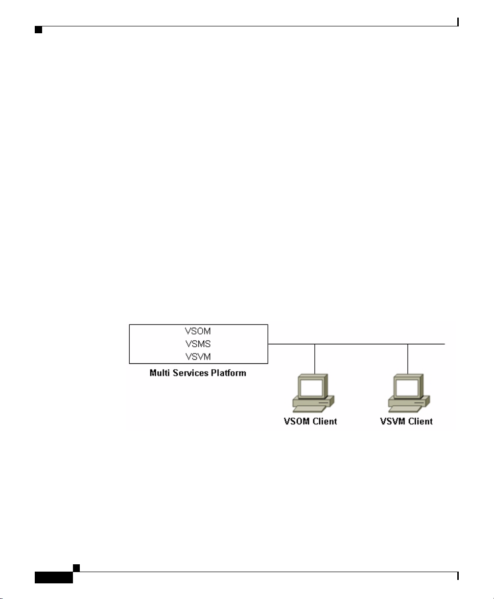
In the simplest single-site scenario, one Multi Services Platform runs all VSM
components (VSOM, VSMS, and VSVM). A deployment if this type might be
appropriate for a small deployment of up to a few dozen cameras.
illustrates this scenario.
Chapter 1 Overview
Figure 1-1
1-12
Figure 1-1 Single Site Deployment with One Multi Services Platform
A single site deployment can include many Multi Service Platforms. In this
situation, VSOM runs on one Multi Service Platform, either by itself or with other
VSM software. The other Multi Service Platforms run VSMS. A deployment of
this type allows scaling the solution to address wiring requirements and to support
a large number of cameras and increased retention rates.
Figure 1-2 illustrates a single site deployment with three Multi Service Platforms,
one that runs VSOM and VSVM, and two that run VSMS.
Cisco Video Surveillance Manager Getting Started Guide, Release 4.2/6.2
OL-19733-01
Page 19

Chapter 1 Overview
Figure 1-2 Single Site Deployment with Several Multi Services Platforms
Deployment Scenarios
Multiple Site Deployment with Centralized VSM Management
In a multiple site deployment, Multi Services Platforms at separate locations
connect through a wide area network (WAN). Each location can have one or more
Multi Services Platforms and client systems can access VSM if they can connect
to the network. These deployments can be designed for centralized or distributed
management of VSM and requires WAN link connection speeds that can support
the bandwidth that you require.
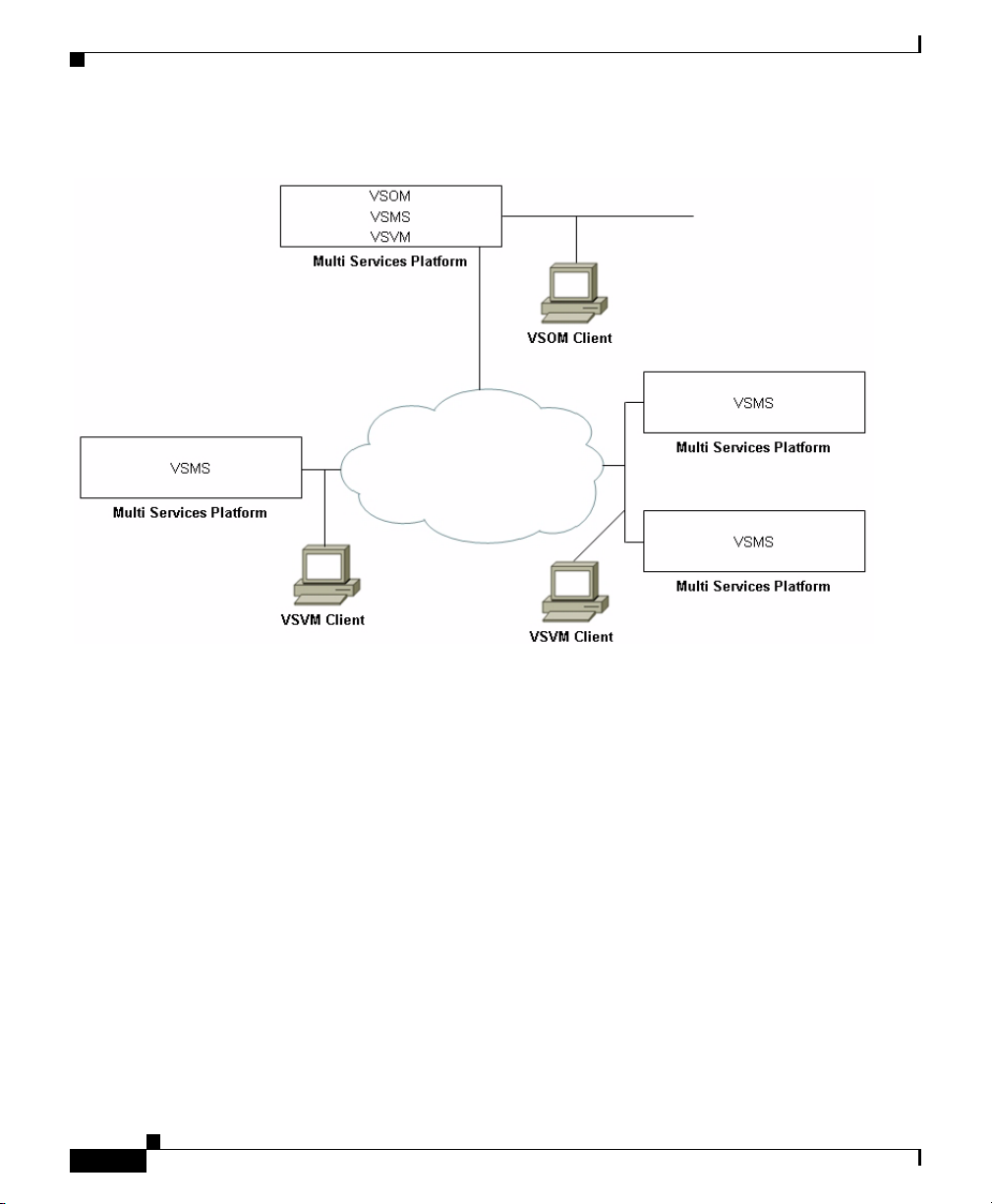
In a centralized VSM management deployment, VSOM runs on one Multi Service
Platform, either by itself or with other VSM software. The other Multi Service
Platforms can run VSMS and VSVM in any combination. A deployment of this
type might be appropriate for an enterprise with distributed locations that wants
to manage and operate VSM software from a central location.
Figure 1-3 illustrates an example of a basic multiple site deployment with
centralized VSM management.
Cisco Video Surveillance Manager Getting Started Guide, Release 4.2/6.2
OL-19733-01
1-13
Page 20
Deployment Scenarios
Figure 1-3 Multiple Site Deployment—Centralized VSM Management
Chapter 1 Overview
1-14
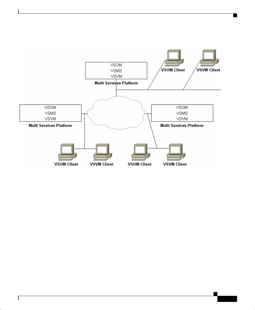
In a distributed VSM management deployment, one Multi Services Platform at
each site runs VSOM. Other VSM software may also run on that server, or may
run in any combination on other Multi Services Platforms at the site. VSM is
configured and managed independently at each site. A deployment of this type
might be appropriate for an enterprise with autonomous branch locations that
wants to manage and operate VSM locally but that also wants access to VSM at
each site.
Figure 1-3 illustrates an example of a basic multiple site deployment with
distributed VSM management.
Cisco Video Surveillance Manager Getting Started Guide, Release 4.2/6.2
OL-19733-01
Page 21
Chapter 1 Overview
Figure 1-4 Multiple Site Deployment—Distributed VSM Management
Deployment Scenarios
OL-19733-01
Cisco Video Surveillance Manager Getting Started Guide, Release 4.2/6.2
1-15
Page 22

Deployment Scenarios
Chapter 1 Overview
1-16
Cisco Video Surveillance Manager Getting Started Guide, Release 4.2/6.2
OL-19733-01
Page 23

CHA P T ER
2
Setting Up and Configuring the Multi Services Platform
The Cisco Multi Services Platform comprises a set of server models that run Cisco
VSM software and provide recording and storage of streams from surveillance
cameras. The servers are available in 1 RU, 2 RU, and 4 RU models, and provide
varying amounts of video storage. For more information, see the
Services Platform” section on page 1-9.
The chapter guides you through installing, setting up, and performing the initial
configuration of your Cisco Multi Services Platform. After you complete the
procedures that this chapter describes, you can configure the Cisco VSM software
and begin to operate your video surveillance system.
Installation, set up, and configuration involves a series of steps that you perform
in sequence.
chapter includes detailed procedures for each step.
Table 2-1 provides an overview of these steps. The rest of this
“Cisco Multi
OL-19733-01
Step 1
Step 2
Ta b l e 2-1 Overview of Installation and Set Up Tasks
Tas k Description
Unpack the Multi Services Platform. Remove the Multi Services Platform
components from the shipping boxes
and make sure that you have received
all items.
Rack mount the Multi Services
Platform.
Cisco Video Surveillance Manager Getting Started Guide, Release 4.2/6.2
Attach rack rails to the Multi Services
Platform and install the device in a 19
inch rack.
2-1
Page 24

Unpacking the Multi Services Platform
Table 2-1 Overview of Installation and Set Up Tasks (continued)
Task Description
Step 3
Step 4
Install hard drives, if needed. If you received the Multi Services
Connect the Multi Services Platform to
power, your network, and control
devices.
Step 5
Configure basic settings on the Multi
Services Platform.
This chapter contains the following sections, which include detailed instructions
for installing, setting up, and configuring the Multi Services Platform:
• Unpacking the Multi Services Platform, page 2-2
• Mounting the Multi Services Platform in a Rack, page 2-4
Chapter 2 Setting Up and Configuring the Multi Services Platform
Platform 2 RU or 4 RU model, install
the hard drives that you received with
the server.
Hard drives are preinstalled in the 1 RU
model.
Connect a monitor, keyboard, and
mouse to the server, and connect the
server to power and to your network.
Access the YaST Control Center on the
Multi Service Platform and configure
network settings, the system time, and
(optionally) NTP settings.
• Installing Hard Drives, page 2-10
• Connecting to Power, the Network, and External Devices, page 2-11
• Performing the Initial Configuration of the Multi Services Platform,
page 2-11
• Where to Go from Here, page 2-29
Unpacking the Multi Services Platform
A Multi Services Platform ships in one, two, or three boxes, depending on the
model and number of hard drives that your ordered:
• 1 RU model—Ships in one box that contains the chassis with hard drives
preinstalled.
Cisco Video Surveillance Manager Getting Started Guide, Release 4.2/6.2
2-2
OL-19733-01
Page 25

Chapter 2 Setting Up and Configuring the Multi Services Platform
• 2 RU model—Ships in two boxes. One box contains the chassis and one box
contains from 4 to 12 hard drives.
• 4 RU model—Ships in two or three boxes. One box contains the chassis. If
you ordered up to 12 hard drives, they are included in one additional box. If
you ordered more than 12 hard drives, they are included in two additional
boxes.
To unpack the Multi Services Platform, follow these steps:
Procedure
Step 1 If your shipment includes two or three boxes, make sure that the serial number
that is printed on the shipping label on each box is the same.
Caution If the serial numbers are not identical, contact Cisco or your Cisco partner before
you set up the system. Operating a Multi Services Platform with mismatched
components causes the system to rebuild the disk array and prevents the system
from operating.
Unpacking the Multi Services Platform
OL-19733-01
Step 2 Carefully open each shipping box and remove its contents.
Step 3 Make sure that the box in which the chassis shipped includes these items:
• Rail assemblies for rack mounting
• SUSE license and activation packet
• Regulatory Compliance and Safety Information document
• Envelope that contains the following:
–
Getting Started with Cisco Video Surveillance Manager Products
–
Recovery disk
–
End User License and Warranty Information disk
–
One or two power cables (depending on how many power supplies you
ordered for your server).
–
Screws and washers for rack mounting
Cisco Video Surveillance Manager Getting Started Guide, Release 4.2/6.2
2-3
Page 26

Chapter 2 Setting Up and Configuring the Multi Services Platform
Mounting the Multi Services Platform in a Rack
Note If your shipment includes more than one Multi Services Platform, make sure that
the serial number of each Multi Services Platform matches the hard drives that are
intended for it, as described in the previous procedure.
Mounting the Multi Services Platform in a Rack
The Multi Services Platform is designed to be installed in a standard 19-inch rack.
The chassis ships with one set of rail assemblies and the mounting screws and
washers that you need to secure the system in a rack.
You also will need a medium size Phillips Head screwdriver and at least two
people to position the Multi Services Platform in a rack.
The following sections describe how to rack mount the Multi Services Platform:
• Preparing to Rack Mount, page 2-4
• Rack Mounting, page 2-6
Preparing to Rack Mount
Before you install the Multi Services Platform in a rack, review the following
guidelines:
Choosing a Location
• Leave approximately 25 inches of clearance in front of the rack to enable you
to open its front door completely, if applicable.
• Leave approximately 30 inches of clearance in back of the rack to allow for
sufficient air flow and ease of servicing.
• The Multi Services Platform is intended for installation in a restricted access
location, such as a dedicated equipment room or service closet.
• Make sure that the rack is in an environment that meets these requirements
for the Multi Services Platform:
–
Operating temperature—50 to 95 °F (10 to 35 °C)
–
Operating humidity—8 to 90% non-condensing
Cisco Video Surveillance Manager Getting Started Guide, Release 4.2/6.2
2-4
OL-19733-01
Page 27

Chapter 2 Setting Up and Configuring the Multi Services Platform
Rack Precautions
• Ensure that the leveling jacks on the bottom of the rack are extended to the
floor with the full weight of the rack resting on them.
• In a single rack installation, attach stabilizers to the rack.
• In a multiple rack installation, couple the racks to each other.
• Make sure that the rack is stable before extending a component from the rack.
• Extend only one component from a rack at a time. Extending two or more
components may cause the rack to become unstable.
General Precautions
• Determine the placement of each component in the rack before you install the
rails.
• Install the heaviest components on the bottom of the rack first, then work up.
• Use a regulating uninterruptible power supply (UPS) to protect a device from
power surges, and voltage spikes and to keep the device operating if a power
failure occurs.
• Close the front door of the rack, if applicable.
Mounting the Multi Services Platform in a Rack
OL-19733-01
• A Multi Services Platform with hard drives and rails installed is heavy. Make
sure that you have assistance when moving it and placing it into a rack.
Rack Mounting Considerations
• Make sure to install the Multi Services Platform in an environment that is
within its rated operating temperature and humidity range (see Cisco Physical
Security Multi Services Platform User Guide). If the Multi Services Platform
is installed in a closed or multi-unit rack assembly, be aware that the ambient
operating temperature of the rack environment may be greater than the
ambient temperature of the room.
• Make sure that there is sufficient air flow for safe operation of the Multi
Services Platform.
• Leave at least 1 rack unit (RU) of space between devices in the same rack.
• Mount the Multi Services Platform in a manner that ensures that a hazardous
condition does not arise due to uneven mechanical loading.
Cisco Video Surveillance Manager Getting Started Guide, Release 4.2/6.2
2-5
Page 28

Mounting the Multi Services Platform in a Rack
• Consider the connection of equipment to the power supply circuitry and the
effect that possible overloading of circuits may have on overcurrent
protection and power supply wiring. Consider equipment nameplate ratings
when addressing this issue.
• Maintain a reliable ground. The rack itself should be grounded. Pay particular
to power supply connections other than direct connections to the branch
circuit (for example, power strips).
Rack Mounting
To install the Multi Services Platform in a rack, perform the following procedure.
You will need a medium-size Phillips-head screwdriver to secure the rails to the
Multi Services Platform chassis and to the rack.
Note • There are a variety of racks available. The procedure for your rack may be
slightly different than the following instructions. See the installation
instructions for your rack for additional information.
• The figures in these sections illustrate the 4 RU model. The procedures are
similar for 1 RU and 2
Chapter 2 Setting Up and Configuring the Multi Services Platform
RU models.
.
Procedure
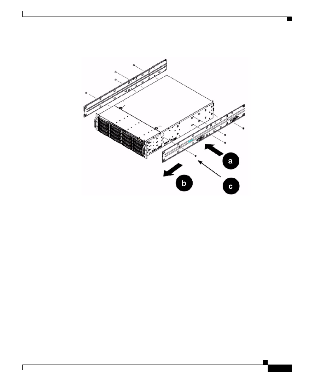
Step 1 Attach the inner rack rails to the Multi Services Platform.
There are two inner rack rails. One attaches to each side of the Multi Services
Platform. To attach these rails, see
Cisco Video Surveillance Manager Getting Started Guide, Release 4.2/6.2
2-6
Figure 2-1 and perform the actions that follow.
OL-19733-01
Page 29
Chapter 2 Setting Up and Configuring the Multi Services Platform
Figure 2-1 Attaching Inner Rack Rails
Mounting the Multi Services Platform in a Rack
OL-19733-01
a. Place the inner rack rail on one side of the chassis, aligning the hooks of the
chassis with the holes in the rail.
The rail marked R attaches to the right of the chassis as you face the front of
the chassis. The rail marked L attaches to the left. The wheels on the rails
should face away from the chassis and the locking tabs on the rails should
face the bottom of the chassis.
b. Slide the rail toward to front of the chassis.
c. Secure the rail to the chassis with four 1/2 inch (6.35 mm) screws (provided).
d. Repeat this step for the other inner rack rail.
Step 2 Attach the outer rack rails to the Multi Services Platform.
There are two outer rack rails. One attaches to each side of the rack and each
connects to an inner rack rail to hold the Multi Services Platform in place. Each
outer rack rail consists of two brackets. The brackets allow the rails to extend
between 30 inches and 33 inches so that they can fit racks of various sizes. To
attach these rails, see
Cisco Video Surveillance Manager Getting Started Guide, Release 4.2/6.2
Figure 2-2 and perform the actions that follow.
2-7
Page 30

Mounting the Multi Services Platform in a Rack
Figure 2-2 Outer Rack Rails
a. Make sure that the right short and long outer rack rail brackets are connected
to each other and that the left short and long outer rack rail brackets are
connected to each other.
Chapter 2 Setting Up and Configuring the Multi Services Platform
2-8
The brackets are marked R and L. To connect the brackets, align the pin on
the small bracket with the slot on the corresponding large bracket, align the
two pins on the large bracket with the slots on the small bracket, and slide the
brackets together.
b. Attach the outer rack rails to the rack, following these guidelines:
–
The outer rack rail marked R attaches to the right of the rack as you face
the front of the rack. The one marked L attaches to the left of the rack.
–
The long outer bracket faces the front of the rack and the short bracket
faces the rear of the rack.
–
The bracket flanges overlap the outer edge of the rack mounting rail.
–
Secure the long bracket to the front of the rack with two 1/2 inch (12.7
mm) screws, and secure the short bracket to the rear of the rack with three
1/2 inch (12.7 mm) screws. The screws are provide with your Multi
Services Platform.
Step 3 Place the Multi Services Platform in a rack by referring to Figure 2-3 and
performing the actions that follow.
Cisco Video Surveillance Manager Getting Started Guide, Release 4.2/6.2
OL-19733-01
Page 31

Chapter 2 Setting Up and Configuring the Multi Services Platform
Figure 2-3 Placing the Server in a rack
Mounting the Multi Services Platform in a Rack
OL-19733-01
a. Confirm that the inner and outer rack rails are installed on the Multi Services
Platform and on the rack.
b. Align the chassis inner rack rails with the front of the outer rack rails.
c. Slide the chassis inner rack rails into the outer rack rails, keeping even
pressure on both sides of the device.
You may have to depress the locking tabs on the inner rack rail when inserting
the device.
d. (Optional) Insert and tighten the thumbscrews that hold the front of the server
to the rack.
Cisco Video Surveillance Manager Getting Started Guide, Release 4.2/6.2
2-9
Page 32

Installing Hard Drives
Installing Hard Drives
If you ordered a Multi Services Platform 2 RU or 4 RU model, you must install
the hard drives that you ordered for the system. To install hard drives, perform the
following procedure. Each of the hard drives that you received should be the same,
so you can install them in any order and into any open slot on the front of the Multi
Services Platform.
Caution Make sure that each hard drive includes a label with a serial number that is
identical to the serial number of the Multi Services Platform chassis. Operating a
Multi Services Platform with mismatched hard drives causes the system to rebuild
the disk array and prevents the system from operating.
Procedure
Step 1 Press the red handle-release button on the front of the hard drive.
The drive handle extends from the front of the hard drive.
Chapter 2 Setting Up and Configuring the Multi Services Platform
2-10
Step 2 With the red handle-release button of the hard drive facing toward you and to the
right, push the drive straight into an open slot on the front of the Multi Services
Platform until you feel resistance.
Step 3 Push the drive handle toward the hard drive until the handle locks into place.
Step 4 Repeat these steps until each hard drive is installed.
Tip You may find it easiest to install the drives from the top down and from
the right to the left. This approach allows the drives to slide into the slots
more easily.
Cisco Video Surveillance Manager Getting Started Guide, Release 4.2/6.2
OL-19733-01
Page 33

Chapter 2 Setting Up and Configuring the Multi Services Platform
Connecting to Power, the Network, and External Devices
Connecting to Power, the Network, and External
Devices
After you mount the Multi Services Platform in a rack and install the hard drives,
you are ready to connect a monitor, keyboard, and mouse to the server, and to
connect the server to power and to your network. To make these connections,
follow these steps:
Procedure
Step 1 Connect a monitor, keyboard, and mouse to the appropriate ports on the back of
the Multi Services Platform.
Step 2 Connect a Category 5 or higher network cable to either network port on the back
of the Multi Services Platform and to your network switch.
Step 3 Take either of these actions to connect power to the Multi Services Platform:
• If your Multi Services Platform is configured with one power supply, connect
the provided power cable to the power port on the back of the Multi Services
Platform, then plug the cable into an electrical outlet.
• If your Multi Services Platform is configured with two power supplies,
connect the two provided power cables to the two power ports on the back of
the Multi Services Platform, then plug each cable into an electrical outlet.
Performing the Initial Configuration of the Multi Services Platform
After you connect a monitor, keyboard, and mouse to the Multi Services Platform,
and you connect it to power and to your network, you are ready to power on the
server and perform the initial configuration that is required for Cisco VSM. Initial
configuration involves setting options for the following:
• Network settings—Options that the Multi Services Platform requires to
operate on you network.
Cisco Video Surveillance Manager Getting Started Guide, Release 4.2/6.2
OL-19733-01
2-11
Page 34

Chapter 2 Setting Up and Configuring the Multi Services Platform
Performing the Initial Configuration of the Multi Services Platform
• System time and date—Time and date in the location that the Multi Services
Platform is to operate.
• Network Time Protocol (NTP)—Options that the Multi Services Platform
requires to synchronize its clock with an NTP server. Configuring NTP is
optional but recommended.
The following sections describe in detail how to perform the initial configuration
of a Multi Services Platform:
• Powering On the System and Accessing the YaST Control Center, page 2-12
• Configuring Network Settings, page 2-15
• Setting the System Time, page 2-21
• Configuring NTP, page 2-24
If you already collected the configuration values that are described in the
“Information Required for Configuring a Multi Services Platform” section on
page 1-4, refer to that information as you perform the following procedures.
Powering On the System and Accessing the YaST Control Center
2-12
After you connect a monitor, keyboard, and mouse to your Multi Services
Platform, and connect it to power and to your network, you are ready perform the
initial configuration of the server.
You perform the initial configuration procedures from the YaST Control Center
on the Multi Services Platform. To access the YaST Control Center, follow these
steps:
Procedure
Step 1 Power on the Multi Services Platform by pressing the power button on its front
panel (see
Figure 2-4 Power Button
Cisco Video Surveillance Manager Getting Started Guide, Release 4.2/6.2
Figure 2-4).
OL-19733-01
Page 35

Chapter 2 Setting Up and Configuring the Multi Services Platform
Performing the Initial Configuration of the Multi Services Platform
The system boots up. It displays several screens of information during this
process. It also displays several prompts for information or optional actions.
Note Do not respond to the prompts that appear during boot up. Instead, let the
system accept the default values and continue with the boot process.
Step 2 When the system prompts you for a user name and password, take these actions:
a. In the Username field, enter root.
The user name is not case sensitive.
b. In the Password field, enter secur4u.
The password is case sensitive.
c. Click the return button next to the Password field, or press the Enter key.
The server desktop appears.
Step 3 Click the programs menu icon , which appears in the lower left corner of
your screen.
Choose System > YaST, as shown in Figure 2-5.
OL-19733-01
Cisco Video Surveillance Manager Getting Started Guide, Release 4.2/6.2
2-13
Page 36

Chapter 2 Setting Up and Configuring the Multi Services Platform
Performing the Initial Configuration of the Multi Services Platform
Figure 2-5 Accessing the YaST Control Center
2-14
The YaST Control Center window appears, as shown in Figure 2-6.
Cisco Video Surveillance Manager Getting Started Guide, Release 4.2/6.2
OL-19733-01
Page 37

Chapter 2 Setting Up and Configuring the Multi Services Platform
Performing the Initial Configuration of the Multi Services Platform
Figure 2-6 YaST Control Center Window
Note The YaST Control Center times out after 5 minutes of inactivity. If a timeout
occurs, enter the password secur4u to redisplay the Control Center.
Configuring Network Settings
This section explains how to configure the settings that the Multi Services
Platform requires to operate on your network. To configure these settings, follow
these steps:
Procedure
Step 1 Access the YaST Control Center window as described in the “Powering On the
System and Accessing the YaST Control Center” section on page 2-12.
Step 2 In the left panel of the YaST Control Center window, click Network Devices, then
click Network Card in the right panel, as shown in
Cisco Video Surveillance Manager Getting Started Guide, Release 4.2/6.2
OL-19733-01
Figure 2-7.
2-15
Page 38

Chapter 2 Setting Up and Configuring the Multi Services Platform
Performing the Initial Configuration of the Multi Services Platform
Figure 2-7 Accessing Network Configuration Options
The YaST2 window appears, as shown in Figure 2-8.
2-16
Cisco Video Surveillance Manager Getting Started Guide, Release 4.2/6.2
OL-19733-01
Page 39

Chapter 2 Setting Up and Configuring the Multi Services Platform
Performing the Initial Configuration of the Multi Services Platform
Figure 2-8 YaST2 Window
OL-19733-01
Step 3 In the YaST2 window, make sure that the Traditional Method with ifup radio
button in the Network Setup Method area is selected (see
Figure 2-8), then click
Next.
Step 4 Take these actions:
a. Make sure that the first controller that is listed in the Network Card
Configuration Overview area is selected, as shown in
Note The network cards that appear on your system may be different than
Figure 2-9.
the ones shown here.
Cisco Video Surveillance Manager Getting Started Guide, Release 4.2/6.2
2-17
Page 40

Chapter 2 Setting Up and Configuring the Multi Services Platform
Performing the Initial Configuration of the Multi Services Platform
Figure 2-9 Choosing a Network Card
b. Click Edit at the bottom of the screen.
The Network Address Setup area appears, as shown in Figure 2-10.
2-18
Cisco Video Surveillance Manager Getting Started Guide, Release 4.2/6.2
OL-19733-01
Page 41

Chapter 2 Setting Up and Configuring the Multi Services Platform
Performing the Initial Configuration of the Multi Services Platform
Figure 2-10 Network Address Setup Area
OL-19733-01
Step 5 Make sure that the Address tab is selected in the Network Address Setup area,
then take these actions:
a. Click the Static Address Setup radio button.
b. In the IP Address field, enter the IP address for the server.
c. In the Subnet Mask field, enter the subnet mask for the server.
d. If you need to assign a default gateway, click the Routing button and continue
to
Step 6. Otherwise, skip to Step 7.
Cisco Video Surveillance Manager Getting Started Guide, Release 4.2/6.2
2-19
Page 42
Chapter 2 Setting Up and Configuring the Multi Services Platform
Performing the Initial Configuration of the Multi Services Platform
Step 6 In the Routing Configuration area, take these actions:
a. In the Default Gateway field, enter the default gateway for the server, if
applicable in your network configuration.
b. Click OK.
The Network Address Setup area appears again.
Step 7 In the Network Address Setup area, take these actions:
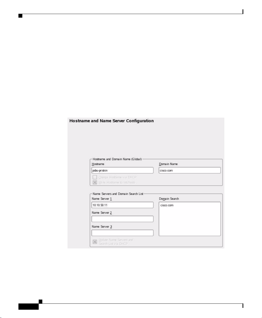
a. Click the Hostname and Name Server button to display the Hostname and
Name Server Configuration area, as shown in
Figure 2-11 Hostname and Name Server Configuration Area
Figure 2-11.
2-20
b. In the Hostname field, enter the host name for the server.
c. (Optional) In the Domain Name field, enter the domain name for the server.
If you are not using fully qualified domain names, leave the default domain
name (“site”) in this field.
Cisco Video Surveillance Manager Getting Started Guide, Release 4.2/6.2
OL-19733-01
Page 43

Chapter 2 Setting Up and Configuring the Multi Services Platform
Performing the Initial Configuration of the Multi Services Platform
d. (Optional) If this server will access up to 3 DNS servers, enter the IP address
of the servers in the Name Server 1, Name Server 2, and Name Server 3 fields.
e. (Optional) In the Domain Search field, enter one or more domains for
searching. Separate multiple domains with a comma, space, or carriage
return.
f. Click OK.
Step 8 In the Network Address Setup area, click Next.
The Network Card Configuration Overview area appears.
Step 9 In the Network Card Configuration Overview area, click Finish.
The Multi Services Platform is now operating on the network.
Setting the System Time
This section describes how to set the time for the Multi Services Platform. It is
important to set the time correctly so that the VSM system can accurately
maintain information for video recording.
OL-19733-01
To set the time for the Multi Services Platform, follow these steps:
Procedure
Step 1 Access the YaST Control Center window as described in the “Powering On the
System and Accessing the YaST Control Center” section on page 2-12.
Step 2 In the left panel of the YaST Control Center window, click System, then click
Date and Time in the right panel, as shown in
Cisco Video Surveillance Manager Getting Started Guide, Release 4.2/6.2
Figure 2-12.
2-21
Page 44

Chapter 2 Setting Up and Configuring the Multi Services Platform
Performing the Initial Configuration of the Multi Services Platform
Figure 2-12 Accessing System Time Options
The Clock and Time Zone area appears, as shown in Figure 2-13.
2-22
Cisco Video Surveillance Manager Getting Started Guide, Release 4.2/6.2
OL-19733-01
Page 45

Chapter 2 Setting Up and Configuring the Multi Services Platform
Performing the Initial Configuration of the Multi Services Platform
Figure 2-13 Clock and Time Zone Area
OL-19733-01
Step 3 In the Region panel, click the region in which the MSP is located.
Step 4 In the Time Zone panel, click the time zone in which the MSP is located.
Make sure that UTC is selected from the Hardware Clock Set To drop down list,
as shown in
Figure 2-14 Selecting UTC
Figure 2-14.
Cisco Video Surveillance Manager Getting Started Guide, Release 4.2/6.2
2-23
Page 46

Chapter 2 Setting Up and Configuring the Multi Services Platform
Performing the Initial Configuration of the Multi Services Platform
Step 5 Click Change next to the Time and Date field.
The Change System Date and Time window appears, as shown in Figure 2-15.
Figure 2-15 Change System Date and Time Window
Step 6 In the Change System Date and Time window, take these actions:
a. In the Current Time field, enter the current hour, minutes, and seconds in 24
hour format. You can type these values or use the up and down arrows to
choose them.
b. In the Current Date field, enter the current date in Date/Month/Year format.
c. Click Apply.
Step 7 In the Clock and Time Zone area, click Accept.
Configuring NTP
This section describes how to configure NTP for your Multi Services Platform.
NTP allows the Multi Services Platform clock to synchronize with Coordinated
Universal Time (UTC) and ensures that the system clock remains consistently
accurate. Cisco strongly recommends that you configure NTP for your system.
Cisco Video Surveillance Manager Getting Started Guide, Release 4.2/6.2
2-24
You can type these values or use the up and down arrows to choose them.
OL-19733-01
Page 47

Chapter 2 Setting Up and Configuring the Multi Services Platform
Performing the Initial Configuration of the Multi Services Platform
To configure NTP, follow these steps:
Procedure
Step 1 Access the YaST Control Center window as described in the “Powering On the
System and Accessing the YaST Control Center” section on page 2-12.
Step 2 In the left panel of the YaST Control Center window, click Network Services,
then click NTP Configuration in the right panel, as shown in
Figure 2-16 Accessing NTP Options
Figure 2-16.
OL-19733-01
Step 3 The Advanced NTP Configuration area appears, as shown in Figure 2-17.
Cisco Video Surveillance Manager Getting Started Guide, Release 4.2/6.2
2-25
Page 48

Chapter 2 Setting Up and Configuring the Multi Services Platform
Performing the Initial Configuration of the Multi Services Platform
Figure 2-17 Advanced NTP Configuration Area
2-26
Step 4 Make sure that the During Boot radio button is selected, as shown in Figure 2-18.
Figure 2-18 Choosing the During Boot Radio Button
Step 5 Uncheck the Configure NTP Daemon via DHCP check box, as shown in
Figure 2-19.
Cisco Video Surveillance Manager Getting Started Guide, Release 4.2/6.2
OL-19733-01
Page 49

Chapter 2 Setting Up and Configuring the Multi Services Platform
Performing the Initial Configuration of the Multi Services Platform
Figure 2-19 Unchecking the Configure NTP Daemon via DHCP Check Box
Step 6 Click Add.
Step 7 The New Synchronization area appears, as shown in Figure 2-20.
Figure 2-20 New Synchronization Area
OL-19733-01
Step 8 In the New Synchronization area, make sure that the Server radio button is
selected, and click Next.
Step 9 The NTP Server panel appears, as shown in Figure 2-21.
Cisco Video Surveillance Manager Getting Started Guide, Release 4.2/6.2
2-27
Page 50

Chapter 2 Setting Up and Configuring the Multi Services Platform
Performing the Initial Configuration of the Multi Services Platform
Figure 2-21 NTP Server Area
2-28
Step 10 In the NTP Server area, take these actions:
a. In the Address field, enter the IP address or host name of your NTP server.
b. (Optional) Click Tes t to make sure that the Multi Services Platform can
access the NTP server.
c. Check the Use for Initial Synchronization check box.
d. Click OK.
Step 11 In the Advanced NTP Configuration screen, click Finish.
Cisco Video Surveillance Manager Getting Started Guide, Release 4.2/6.2
OL-19733-01
Page 51

Chapter 2 Setting Up and Configuring the Multi Services Platform
Where to Go from Here
Congratulations. If you have successfully completed the procedures that this
chapter describes, your Multi Services Platform is configured and running on your
network. Now you are ready to configure the VSM software, as described in
Chapter 3, “Configuring VSM.”
Where to Go from Here
OL-19733-01
Cisco Video Surveillance Manager Getting Started Guide, Release 4.2/6.2
2-29
Page 52

Where to Go from Here
Chapter 2 Setting Up and Configuring the Multi Services Platform
2-30
Cisco Video Surveillance Manager Getting Started Guide, Release 4.2/6.2
OL-19733-01
Page 53

CHA P T ER
3
Configuring VSM
This provides instructions for performing the basic configuration of VSOM. Basic
configuration involves providing information about VSMS, VSVM, video
encoder, and camera devices that will operate in your VSM deployment, and
scheduling video recording.
This chapter includes these topics:
• Setting the VSOM Log In Page as the Default Web Page, page 3-1
• Configuring VSM, page 3-4
• Where to Go from Here, page 3-46
Setting the VSOM Log In Page as the Default Web Page
OL-19733-01
The following steps describe how to configure VSM so that the VSOM log in page
appears by default when you access an MSP with a web browser. Perform these
steps on each MSP that is to run VSOM.
Procedure
Step 1 Make sure that the Multi Services Platform that is running VSOM is powered up.
Cisco Video Surveillance Manager Getting Started Guide, Release 4.2/6.2
3-1
Page 54

Setting the VSOM Log In Page as the Default Web Page
Step 2 Take either of these actions to access the Management Console:
• From the keyboard and monitor that are attached to the Multi Services
Platform, click the Cisco Video Surveillance Management Console icon on
the server desktop (see
Figure 3-1 Management Console Icon
• From a computer that can access the network in which the Multi Services
Platform is connected, start Internet Explorer version 6 or 7 and enter the IP
address of host name of the Multi Services Platform in the Address field.
• The Video Surveillance Management Console appears (see Figure 3-2).
Figure 3-2 VSM Management Console
Chapter 3 Configuring VSM
Figure 3-1).
3-2
Step 3 Click the Operations Manager link in the Configuration area, as shown in
Figure 3-3.
Cisco Video Surveillance Manager Getting Started Guide, Release 4.2/6.2
OL-19733-01
Page 55

Chapter 3 Configuring VSM
Figure 3-3 Choosing Operations Manager
Setting the VSOM Log In Page as the Default Web Page
OL-19733-01
Step 4 In the dialog box that prompts for a user name and password take these actions:
a. In the Username field, enter root.
The user name is not case sensitive.
b. In the Password field, enter secur4u.
The password is case sensitive.
Step 5 Under Select Homepage, choose the Change default homepage to VSOM radio
button, as shown in
Figure 3-4.
You may need to scroll down to see this option.
Cisco Video Surveillance Manager Getting Started Guide, Release 4.2/6.2
3-3
Page 56

Configuring VSM
Figure 3-4 Choosing the VSOM Default Home Page
Step 6 Click Update.
Configuring VSM
The following sections describe how to make basic configuration settings for
VSM. This process includes configuring options for servers, video encoders (if
needed), cameras, and recording schedules. You can configure cameras and video
encoders even if they are not yet set up in your deployment. After you complete
these configuration procedures, you can display video through the system.
Chapter 3 Configuring VSM
3-4
You can always update configuration settings later. In addition, there are many
advanced configuration settings that you also can make later.
To perform the basic configuration of VSM, review and follow the instructions in
the following sections:
• Accessing Video Surveillance Operations Manager, page 3-5
• Adding Servers, page 3-6
• Adding Video Encoders, page 3-11
• Adding Analog Cameras, page 3-17
• Adding IP Cameras, page 3-26
• Configuring Archives, page 3-37
If you already collected the configuration values that are described in the
“Information Required for Configuring VSM” section on page 1-5, refer to that
information as you perform the following procedures.
Cisco Video Surveillance Manager Getting Started Guide, Release 4.2/6.2
OL-19733-01
Page 57

Chapter 3 Configuring VSM
Accessing Video Surveillance Operations Manager
You perform the basic configuration of VSM by using the VSOM Operations
Manager, which you control through the VSOM Operator pages. You can access
these pages from a client PC that meets the requirements that the
section on page 1-10 describes.
To access the VSOM Operations Manager, perform the following steps.
Before you begin, make sure that you have performed the steps that are described
in the
“Setting the VSOM Log In Page as the Default Web Page” section on
page 3-1.
Procedure
Step 1 On a client PC, take these actions:
a. Start Internet Explorer.
b. Enter the IP address or the host name of the Multi Services Platform server
that is running VSOM.
Step 2 In the dialog box that prompts for a user name and password take these actions:
Configuring VSM
“Client PCs”
OL-19733-01
a. In the Username field, enter root.
The user name is not case sensitive.
b. In the Password field, enter secur4u.
The password is case sensitive.
c. Click OK.
Note If you are prompted to install the ActiveX controller (AXclient), follow
the on-screen prompts to do so. ActiveX is required to display video
through VSM. You are prompted to install the ActiveX controller the first
time that you log into VSOM.
The VSOM Operator page appears, as shown in Figure 3-5.
Cisco Video Surveillance Manager Getting Started Guide, Release 4.2/6.2
3-5
Page 58

Configuring VSM
Chapter 3 Configuring VSM
Figure 3-5 VSOM Operator Page
Adding Servers
Adding servers is the process of configuring information about each Multi
Services Platform that runs VSMS and each Multi Services Platform that runs
VSVM in your VSM deployment. This information includes the name and IP
address or host name of each server. If a Multi Services Platform runs VSMS and
VSVM, add that server twice, once for each component.
To add servers, follow these steps:
Procedure
Step 1 Access the VSOM Operations Manager as described in the “Accessing Video
Surveillance Operations Manager” section on page 3-5.
Cisco Video Surveillance Manager Getting Started Guide, Release 4.2/6.2
3-6
OL-19733-01
Page 59

Chapter 3 Configuring VSM
Step 2 In the VSOM Operator page, click the Admin link, which appears near the top left
of the page (see
Figure 3-6 Admin Link
The Administration area appears.
Step 3 Take the following actions to configure each server that will run VSMS:
a. Click Servers under Devices in the left panel of the VSOM Operator page, as
Figure 3-7 Accessing the Servers Area
shown in
Configuring VSM
Figure 3-6).
Figure 3-7.
OL-19733-01
The Servers area appears.
b. In the Servers area, click Add a New Server, as shown in Figure 3-8.
Cisco Video Surveillance Manager Getting Started Guide, Release 4.2/6.2
3-7
Page 60

Configuring VSM
Chapter 3 Configuring VSM
Figure 3-8 Choosing to Add a Server
c. In the Server Information area in the Details tab, choose Video Surveillance
Media Server (VSMS) from the Server Type drop-down list, as shown in
Figure 3-9.
Figure 3-9 Choosing a VSMS Server Type
3-8
d. In the Server Name field (see Figure 3-10), enter a name for the server.
Enter a descriptive name that can help you identify the server. For example,
enter the location of the server or its primary use. The name can include any
combination of characters and spaces.
Cisco Video Surveillance Manager Getting Started Guide, Release 4.2/6.2
OL-19733-01
Page 61

Chapter 3 Configuring VSM
Figure 3-10 Server Name Field
e. (Optional) In the Description field (see Figure 3-11), enter a description for
Configuring VSM
the server.
For example, the description could include the location or type of the server.
OL-19733-01
Figure 3-11 Description Field
f. In the Host IP/Name field (see Figure 3-12), enter the host name or IP address
of the server that you are adding.
Cisco Video Surveillance Manager Getting Started Guide, Release 4.2/6.2
3-9
Page 62

Configuring VSM
Step 4 If you will use VSVM, take the following actions to configure the server that will
Chapter 3 Configuring VSM
Figure 3-12 Host IP/Name Field
g. Click the Submit button to add the server.
h. Repeat this Step 3 for each server on which you will run VSMS.
run VSVM:
a. Click Servers under Devices in the left panel of the VSOM Operator page, as
shown in
The Servers area appears.
Figure 3-7 on page 3-7.
3-10
b. In the Servers area, click Add a New Server, as shown in Figure 3-8 on
page 3-8.
c. In the Server Information area in the Details tab, choose Video Surveillance
Virtual Matrix (VSVM) from the Server Type drop-down list, as shown in
Figure 3-13.
Cisco Video Surveillance Manager Getting Started Guide, Release 4.2/6.2
OL-19733-01
Page 63

Chapter 3 Configuring VSM
Figure 3-13 Choosing a VSVM Server Type
d. In the Server Name field, enter a name for server.
e. (Optional) In the Description field, enter a description for the server.
Configuring VSM
Enter a descriptive name that can help you identify the server. The name can
include any combination of characters and spaces
For example, the description could include the location or type of the server.
f. In the Host IP/Name field, enter the host name or IP name of the server that
you are adding, followed by
“:8086” is the default port number and appears in this field by default.
g. Click the Submit button to add the server.
Adding Video Encoders
Adding video encoders is the process of configuring information about each video
encoder that will operate in your VSM deployment.
Video encoders convert analog video from analog cameras into digital video that
can be used by VSM. An encoder is identified by an IP address or host name and
by type. In addition, encoders often are secured by a user name and password,
which you should provide as required.
Cisco Video Surveillance Manager Getting Started Guide, Release 4.2/6.2
OL-19733-01
:8086.
3-11
Page 64

Configuring VSM
Step 1 Access the VSOM Operations Manager as described in the “Accessing Video
Step 2 In the VSOM Operator page, click the Admin link, which appears near the top left
Chapter 3 Configuring VSM
Video encoders are required only if your deployment includes analog cameras. If
you will not use video encoders, skip this section.
Procedure
Surveillance Operations Manager” section on page 3-5
of the page (see
Figure 3-14 Admin Link
Figure 3-14).
3-12
The Administration area appears.
Step 3 Click Encoders under Devices in the left panel of the VSOM Operator page, as
shown in
Cisco Video Surveillance Manager Getting Started Guide, Release 4.2/6.2
Figure 3-15.
OL-19733-01
Page 65

Chapter 3 Configuring VSM
Configuring VSM
.
Figure 3-15 Accessing the Encoders Area
The Encoders area appears.
Step 4 In the Encoders area, click Add a New Encoder, as shown in Figure 3-8.
Figure 3-16 Choosing to Add an Encoder
OL-19733-01
Step 5 In the Encoder Information area in the Details tab, take these actions:
a. Choose the model of the video encoder that you are adding from the Encoder
Type drop-down list, as shown in
Cisco Video Surveillance Manager Getting Started Guide, Release 4.2/6.2
Figure 3-17.
3-13
Page 66

Configuring VSM
Chapter 3 Configuring VSM
Figure 3-17 Choosing an Encoder Type
3-14
b. In the Encoder Name field (see Figure 3-18), enter a name for the video
encoder.
Enter a descriptive name that can help you identify the device. The name can
include any combination of characters and spaces.
Cisco Video Surveillance Manager Getting Started Guide, Release 4.2/6.2
OL-19733-01
Page 67

Chapter 3 Configuring VSM
Figure 3-18 Encoder Name Field
c. (Optional) In the Description field (see Figure 3-19), enter a description for
Figure 3-19 Description Field
Configuring VSM
the video encoder.
For example, the description could include the location or type of the video
encoder.
OL-19733-01
d. In the Host IP/Name field (see Figure 3-20), enter the host name or IP name
of the video encoder that you are adding.
Cisco Video Surveillance Manager Getting Started Guide, Release 4.2/6.2
3-15
Page 68

Configuring VSM
Step 6 If the video encoder allows access from VSMS only if VSMS provides valid
Chapter 3 Configuring VSM
Figure 3-20 Host IP/Name Field
authentication credentials, take these actions in the Authentication area in the
Details Tab:
a. In the Username field (see Figure 3-21), enter the user name that VSMS
provides when accessing the video encoder.
The user name is configured on the video encoder and the value that you enter
in this field must match the configured name exactly. The user name can
contain alphabetic and numeric characters only and is case sensitive.
3-16
Figure 3-21 Username Field
b. In the New Password field (see Figure 3-22), enter the password that VSMS
provides when accessing the video encoder.
The password is configured on the video encoder and the value that you enter
in this field must match the configured password exactly. The password can
contain alphabetic and numeric characters only and is case sensitive.
Cisco Video Surveillance Manager Getting Started Guide, Release 4.2/6.2
OL-19733-01
Page 69

Chapter 3 Configuring VSM
Figure 3-22 New Password Field
c. In the Confirm Password field (see Figure 3-23), reenter the password.
Figure 3-23 Confirm Password Field
Configuring VSM
Step 7 Click the Submit button to add the encoder.
Step 8 Repeat Step 4 through Step 7 as needed to add other video encoders.
Adding Analog Cameras
Adding analog cameras is the process of configuring information about the analog
cameras that will operate in your VSM deployment. This information includes the
name of each camera and information about its video stream.
Before you can add analog cameras, you must configure video encoders as
described in the
use analog cameras, skip this section.
Cisco Video Surveillance Manager Getting Started Guide, Release 4.2/6.2
OL-19733-01
“Adding Video Encoders” section on page 3-11. If you will not
3-17
Page 70

Configuring VSM
Step 1 Access the VSOM Operations Manager as described in the “Accessing Video
Step 2 In the VSOM Operator page, click the Admin link, which appears near the top left
Step 3 Click Analog Cameras under Devices in the left panel of the VSOM Operator
Procedure
Surveillance Operations Manager” section on page 3-5
of the page (see
Figure 3-24 Admin Link
The Administration area appears.
page, as shown in
Figure 3-24).
Figure 3-25.
Chapter 3 Configuring VSM
.
3-18
Figure 3-25 Accessing the Analog Cameras Area
The Analog Camera area appears.
Cisco Video Surveillance Manager Getting Started Guide, Release 4.2/6.2
OL-19733-01
Page 71

Chapter 3 Configuring VSM
Step 4 In the Analog Cameras area, click Add a New Analog Camera, as shown in
Figure 3-26.
Figure 3-26 Choosing to Add an Analog Camera
Step 5 In the Camera Information area in the Camera Type tab, take these actions:
a. In the Camera Name field (see Figure 3-27), enter a name for the camera.
Configuring VSM
Enter a descriptive name that can help you identify the camera. The name can
include any combination of characters and spaces.
OL-19733-01
Figure 3-27 Camera Name Field
b. (Optional) In the Description field (see Figure 3-28), enter a description for
the camera.
For example, the description could include the location or type of the camera.
Cisco Video Surveillance Manager Getting Started Guide, Release 4.2/6.2
3-19
Page 72

Configuring VSM
Chapter 3 Configuring VSM
Figure 3-28 Description Field
c. From the Status drop-down list, make sure that Enabled is selected, as shown
in
Figure 3-29.
Figure 3-29 Status Enabled
3-20
d. From the Encoder drop-down list (see Figure 3-30), choose the video encoder
that the camera connects to.
This list displays the video encoders that you added as described in the
“Adding Video Encoders” section on page 3-11.
Cisco Video Surveillance Manager Getting Started Guide, Release 4.2/6.2
OL-19733-01
Page 73

Chapter 3 Configuring VSM
Figure 3-30 Encoder Drop-Down List
e. From the Encoder Channel drop-down list (see Figure 3-31), choose the
Figure 3-31 Encoder Channel Drop-Down List
Configuring VSM
video encoder input port that the camera connects to.
OL-19733-01
Step 6 In the Camera Feed area in the Camera Type tab, take these actions:
a. From the Server drop-down list (see Figure 3-32), choose the VSMS that is
to manage the camera feed.
This list displays the servers that you configured as described in the “Adding
Servers” section on page 3-6.
Cisco Video Surveillance Manager Getting Started Guide, Release 4.2/6.2
3-21
Page 74

Configuring VSM
Chapter 3 Configuring VSM
Figure 3-32 Server Drop-Down List
b. From the Media Type drop-down list (see Figure 3-33), choose the digital
video encoding type for the video stream from the camera.
The options in this list depend on the video encoder that you chose for this
camera.
3-22
Figure 3-33 Media Type Drop-Down List
c. From the Format drop-down list (see Figure 3-34), choose the format for the
video stream from the camera.
The options in this list depend on the video encoder that you chose for this
camera.
Cisco Video Surveillance Manager Getting Started Guide, Release 4.2/6.2
OL-19733-01
Page 75

Chapter 3 Configuring VSM
Figure 3-34 Format Drop-Down List
d. From the Resolution drop-down list (see Figure 3-35), choose the resolution
Figure 3-35 Resolution Drop-Down List
Configuring VSM
for the video stream from the camera.
The options in this list depend on the video encoder that you chose for this
camera.
OL-19733-01
e. For the Transport option (seeFigure 3-36), take one of these actions to
designate the protocol that VSMS uses to obtain video from the encoder (the
available choices depend on the video encoder that you chose for this
camera):
–
To choose Transport Control Protocol (TCP), click the TCP radio button
Cisco Video Surveillance Manager Getting Started Guide, Release 4.2/6.2
3-23
Page 76

Configuring VSM
–
To choose Universal Datagram Protocol (UDP) unicast, click the UDP
radio button
–
To choose UDP multicast, click the UDP radio button, then in the
Multicast Address field enter the multicast address that the video encoder
should use to multicast the video to VSMS
Figure 3-36 Transport Option
Chapter 3 Configuring VSM
3-24
f. If the Bitrate drop-down list appears (see Figure 3-37), choose the bit rate for
the video stream from the camera.
The Bitrate drop-down list appears only if you chose MPEG-2, MPEG-4, or
H.264 for the media type.
Figure 3-37 Bitrate Drop-Down List
Cisco Video Surveillance Manager Getting Started Guide, Release 4.2/6.2
OL-19733-01
Page 77

Chapter 3 Configuring VSM
g. If the Frame Rate drop-down list (seeFigure 3-38), choose the frame rate per
Figure 3-38 Frame Rate Drop-Down List
h. Use the Quality slider (see Figure 3-39) to specify the quality of the video
Configuring VSM
second for the video stream from the camera.
The Frame Rate drop-down list appears only if you chose JPEG for the media
type.
stream.
OL-19733-01
The slider displays a numerical value when you move it. Use these numbers
to help determine the setting that you want as follows:
–
For MPEG-2, MPEG-4, and H.264 media types, values of 1 through 49
designate the relative priority that frame rate has over compression.
Values 50 through 100 designate the relative priority that compression
has over frame rate.
–
For JPEG media type, values of 1 through 100 designate the relative
quality of the video stream. A higher value uses less compression and
provides higher quality, but consumes more bandwidth.
Cisco Video Surveillance Manager Getting Started Guide, Release 4.2/6.2
3-25
Page 78
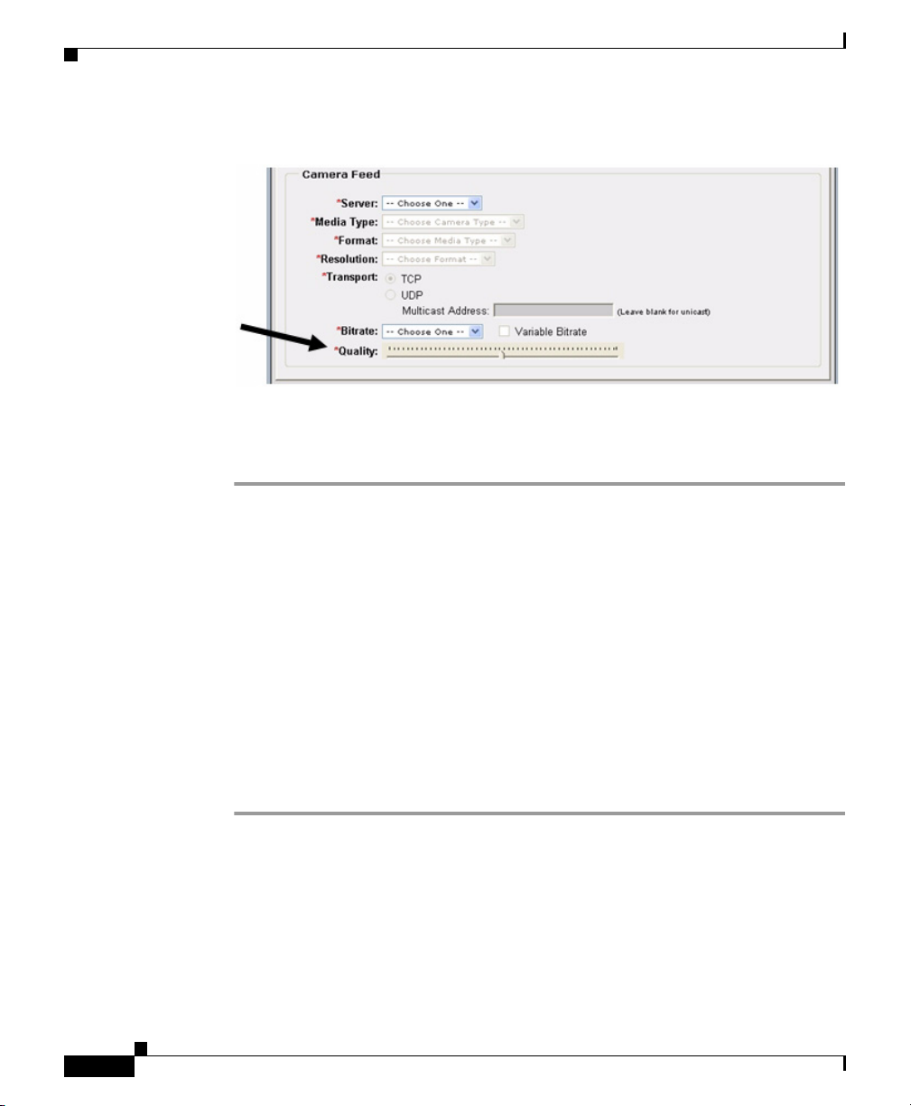
Configuring VSM
Step 7 Click the Submit button to add the analog camera.
Step 8 Repeat Step 4 through Step 7 as needed to add other cameras.
Chapter 3 Configuring VSM
Figure 3-39 Quality Slider
Adding IP Cameras
Adding IP cameras is the process of configuring information about the IP cameras
that will operate in your VSM deployment. This information includes the name of
the camera, information about its video stream, and its log in credentials.
IP cameras (also called network cameras) connect directly to an IP network and
do not require separate encoders.
If you will not use IP cameras, skip this section.
Procedure
Step 1 Access the VSOM Operations Manager as described in the “Accessing Video
Surveillance Operations Manager” section on page 3-5
Cisco Video Surveillance Manager Getting Started Guide, Release 4.2/6.2
3-26
OL-19733-01
Page 79

Chapter 3 Configuring VSM
Step 2 In the VSOM Operator page, click the Admin link, which appears near the top left
of the page. (see
Figure 3-40 Admin Link
The Administration area appears.
Step 3 Click IP/Network Cameras under Devices in the left panel of the VSOM
Operator page.as shown in
Configuring VSM
Figure 3-40).
Figure 3-41.
.
Figure 3-41 Accessing the IP/Network Cameras Area
The IP/Network Cameras area appears.
Step 4 In the IP/Network Cameras area, click Add a New IP/Network Camera.
OL-19733-01
Cisco Video Surveillance Manager Getting Started Guide, Release 4.2/6.2
3-27
Page 80

Configuring VSM
Step 5 In the Camera Information area in the Camera Type tab, take these actions:
Chapter 3 Configuring VSM
Figure 3-42 Choosing to Add an IP/Network Camera
a. In the Camera Name field (see Figure 3-43, enter a name for the analog
camera.
Enter a descriptive name that can help you identify the camera. The name can
include any combination of characters and spaces.
Figure 3-43 Camera Name Field
3-28
b. (Optional) In the Description field (see Figure 3-44), enter a description for
the camera.
For example, the description could include the location or type of the camera.
Cisco Video Surveillance Manager Getting Started Guide, Release 4.2/6.2
OL-19733-01
Page 81

Chapter 3 Configuring VSM
Figure 3-44 Description Field
c. From the Camera Type drop-down list (see Figure 3-45, choose the model of
Figure 3-45 Camera Type Drop-Down List
Configuring VSM
the camera that you are adding.
OL-19733-01
d. In the Host IP/Name field (see Figure 3-46), enter the IP address or host name
of the camera.
Cisco Video Surveillance Manager Getting Started Guide, Release 4.2/6.2
3-29
Page 82

Configuring VSM
Chapter 3 Configuring VSM
Figure 3-46 Host IP-Name Field
e. From the Status drop-down list (see Figure 3-47), make sure that Enabled is
selected.
Figure 3-47 Status Drop-Down List
3-30
Step 6 In the Camera Feed area in the Camera Type tab, take these actions:
a. From the Server drop-down list (see Figure 3-48), choose the VSMS that will
manage the video stream.
This list displays the servers that you configured as described in the “Adding
Servers” section on page 3-6.
Cisco Video Surveillance Manager Getting Started Guide, Release 4.2/6.2
OL-19733-01
Page 83

Chapter 3 Configuring VSM
Figure 3-48 Server Drop-Down List
b. From the Media Type drop-down list (see Figure 3-49), choose the digital
Figure 3-49 Media Type Drop-Down List
Configuring VSM
video encoding type for the video stream from the camera.
OL-19733-01
c. From the Format drop-down list (see Figure 3-50), choose the format for the
video stream from the camera.
The options in this list depend on the camera model that you chose.
Cisco Video Surveillance Manager Getting Started Guide, Release 4.2/6.2
3-31
Page 84

Configuring VSM
Chapter 3 Configuring VSM
Figure 3-50 Format Drop-Down List
d. From the Resolution drop-down list (see Figure 3-51), choose the resolution
for the video stream from the camera.
The options in this list depend on the camera model that you chose.
Figure 3-51 Resolution Drop-Down List
3-32
e. For the Transport option (see Figure 3-52), take one of these actions to
designate the protocol that VSMS uses to obtain video from the encoder (the
available choices depend on the model of the IP camera):
–
To choose Transport Control Protocol (TCP), click the TCP radio button
–
To choose Universal Datagram Protocol (UDP) unicast, click the UDP
radio button
Cisco Video Surveillance Manager Getting Started Guide, Release 4.2/6.2
OL-19733-01
Page 85

Chapter 3 Configuring VSM
Figure 3-52 Transport Option
Configuring VSM
–
To choose UDP multicast, click the UDP radio button, then in the
Multicast Address field enter the multicast address that camera should
use to multicast the video to VSMS
f. From the Bitrate drop-down list (see Figure 3-53), choose the bit rate for the
video stream from the camera.
OL-19733-01
The Bitrate drop-down list appears only if you chose MPEG-2, MPEG-4, or
H.264 for the media type.
Figure 3-53 Bitrate Drop-Down List
Cisco Video Surveillance Manager Getting Started Guide, Release 4.2/6.2
3-33
Page 86

Configuring VSM
Chapter 3 Configuring VSM
g. From the Frame Rate drop-down list (see Figure 3-54), choose the frame rate
per second for the video stream from the camera.
The Frame Rate drop-down list appears only if you chose JPEG for the media
type.
Figure 3-54 Frame Rate Drop-Down List
h. Use the Quality slider (see Figure 3-55) to specify the quality of the video
stream.
The slider displays a numerical value when you move it. Use these numbers
to help determine the setting that you want as follows:
3-34
–
For MPEG-2, MPEG-4, and H.264 media types, values of 1 through 49
designate the relative priority that frame rate has over compression.
Values of 50 through 100 designate the relative priority that compression
has over frame rate.
–
For JPEG media type, values of 1 through 100 designate the relative
quality of the video stream. A higher value uses less compression and
provides higher quality, but consumes more bandwidth.
Cisco Video Surveillance Manager Getting Started Guide, Release 4.2/6.2
OL-19733-01
Page 87

Chapter 3 Configuring VSM
Figure 3-55 Quality Slider
Step 7 In the Camera requires authentication area in the Camera Type tab, take these
actions:
a. Check the Camera requires authentication check box (see Figure 3-56) if
Configuring VSM
the camera allows access from VSMS only if VSMS provides valid
authentication credentials.
OL-19733-01
Figure 3-56 Camera Requires Authentication Check Box
b. In the Username field (see Figure 3-57), enter the user name that VSMS
provides when accessing the camera.
The user name is configured on the camera and the value that you enter in this
field must match the configured name exactly. The user name can contain
alphabetic and numeric characters only and is case sensitive.
Cisco Video Surveillance Manager Getting Started Guide, Release 4.2/6.2
3-35
Page 88

Configuring VSM
Chapter 3 Configuring VSM
Figure 3-57 Username Field
c. In the Password field (see Figure 3-58), enter the password that VSMS
provides when accessing the camera.
The password is configured on the camera and the value that you enter in this
field must match the configured password exactly. The password can contain
alphabetic and numeric characters only and is case sensitive.
Figure 3-58 Password Field
3-36
d. In the Confirm Password field (see Figure 3-59), reenter the password.
Figure 3-59 Confirm Password Field
Step 8 Click the Submit button to add the analog camera.
Step 9 Repeat Step 4 through Step 8 as needed to add other cameras.
Cisco Video Surveillance Manager Getting Started Guide, Release 4.2/6.2
OL-19733-01
Page 89

Chapter 3 Configuring VSM
Configuring Archives
An archive is a recording of the feed from a camera in your VSM deployment.
Configuring archives is the process of designating a camera feed that you want to
record, setting parameters for the recording, and specifying a schedule for the
recording. The feed includes video and, depending on the camera and VSM
configuration, may include audio.
A recorded feed is called an archive. You can display archives when you need to
review a video surveillance feed.
You can configure any of the following schedule types for a recording:
• Simple Schedule—Recording occurs during one or more designated time
periods. You specify the start date and time and end date and time for each
period.
• Recurring Schedule—Recording occurs on a weekly schedule. For each day,
you can the time range or ranges in which recording occurs, and you can
specify start and stop dates for the entire schedule.
• Continuous Loop—Records continuously and the system retains video for the
time period that you designate.
Configuring VSM
OL-19733-01
Procedure
Step 1 Access the VSOM Operations Manager as described in the “Accessing Video
Surveillance Operations Manager” section on page 3-5
Step 2 In the VSOM Operator page, click the Admin link, which appears near the top left
of the page. (see
Figure 3-60 Admin Link
Figure 3-60).
The Administration area appears.
Cisco Video Surveillance Manager Getting Started Guide, Release 4.2/6.2
3-37
Page 90

Configuring VSM
Step 3 Click Archives under Video Feeds in the left panel of the VSOM Operator page,
as shown in
Figure 3-61 Choosing Archives
Figure 3-61.
Chapter 3 Configuring VSM
3-38
Step 4 In the Archives area, click Start/Schedule a New Archive, as shown in
Figure 3-62.
Cisco Video Surveillance Manager Getting Started Guide, Release 4.2/6.2
OL-19733-01
Page 91

Chapter 3 Configuring VSM
Figure 3-62 Choosing to Schedule a New Archive
Step 5 In the Archive Source area in the Feeds tab, take these actions:
a. Click the radio button that corresponds to the camera feed that you want to
Figure 3-63 Choosing to Schedule a New Archive
record (see
Configuring VSM
Figure 3-63 for an example).
OL-19733-01
b. Click Next.
Step 6 In the Archive Information area in the Details tab, take these actions:
a. In the Archive Name field (see Figure 3-64), enter a name for the camera.
Enter a descriptive name that can help you identify the camera. The name can
include any combination of characters and spaces.
Cisco Video Surveillance Manager Getting Started Guide, Release 4.2/6.2
3-39
Page 92

Configuring VSM
Chapter 3 Configuring VSM
Figure 3-64 Archive Name Field
b. (Optional) In the Description field (see Figure 3-65), enter a description for
the archive.
Figure 3-65 Description Field
3-40
c. From the Status drop-down list (see Figure 3-66), make sure that Enabled is
selected.
Cisco Video Surveillance Manager Getting Started Guide, Release 4.2/6.2
OL-19733-01
Page 93

Chapter 3 Configuring VSM
Figure 3-66 Status Drop-Down List
d. From the Force Start drop-down list (see Figure 3-67), choose either of these
Configuring VSM
options:
–
Default—VSMS verifies whether there is enough capacity to store the
archive that you are configuring. If there is not enough capacity when you
submit the archive, the archive operation does not start and VSMS
generates an error message.
–
Force—VSMS starts recording even if there is not enough capacity for
the archive that is configured. If you choose this option, make sure to
provide enough disk space for the archive that you want. If the system
runs out of disk space, it begins to delete the oldest retained video to
make room for new video.
OL-19733-01
Cisco Video Surveillance Manager Getting Started Guide, Release 4.2/6.2
3-41
Page 94

Configuring VSM
Chapter 3 Configuring VSM
Figure 3-67 Force Start Drop-Down List
e. From the Keep on Server drop-down list (see Figure 3-68), choose the
number of days that VSMS retains the archive after the recording stops. The
system deletes the archive after this period. If you choose Forever, the
archive is never deleted.
3-42
Figure 3-68 Keep On Server Drop-Down List
Cisco Video Surveillance Manager Getting Started Guide, Release 4.2/6.2
OL-19733-01
Page 95

Chapter 3 Configuring VSM
Step 7 Click the Archive Type tab and take the appropriate actions in the Archive Type
area to designate and configure the archive type:
• To record during one or more designated periods, see Figure 3-69 and take
Figure 3-69 Options for Configuring One or More Recording Periods
Configuring VSM
these actions:
1. Click the Simple Schedule radio button.
2. In the Start on and End On fields, specify the start date and the end date
for the recording. In the corresponding At fields, enter the start time and
end time for the recording.
You can type information in these fields, or you can use the calendar in
the date fields or the drop-down arrows in the time to select information.
3. (Optional) To designate an additional start/stop schedule, click Add
Date(s) and enter the desired dates and times. You can repeat this process
to designate as many start and stop dates and times as needed.
To remove a start/stop schedule, click Remove next to the corresponding
schedule.
OL-19733-01
Cisco Video Surveillance Manager Getting Started Guide, Release 4.2/6.2
3-43
Page 96

Configuring VSM
Chapter 3 Configuring VSM
• To designate a regular weekly schedule for recording, see Figure 3-70 and
take these actions:
1. Click the Recurring Schedule radio button.
2. In the Start On field, type or use the calendar to enter the date on which
the schedule becomes active.
3. Specify the days on which the recording executes during identical time
periods:
a. Check the check box that corresponds to each day on which you want
the recording to execute identically.
b. In the Start At and Stop At fields, enter the times that the recording
starts and stops on the selected day or days.
c. (Optional) To add another time interval for the selected days, click
Add Time Range and enter the start time and stop time in the Start At
and Stop At fields that appear. Repeat as needed to add more time
intervals for these days.
d. (Optional) To specify other days with different schedules, check the
check boxes that correspond to the days, enter start and stop times for as
many ranges as desired, and click Next Weekdays. Repeat as needed.
3-44
4. Specify whether the recurring schedule ends:
- To stop the schedule after a designated number of weekly runs, click the
End After radio button and enter the number of times that the schedule
should run.
- To stop the schedule at the end of the day on a certain date, click the
End by radio button and enter the stop date.
- To run the schedule indefinitely, click the No End Date radio button.
Cisco Video Surveillance Manager Getting Started Guide, Release 4.2/6.2
OL-19733-01
Page 97

Chapter 3 Configuring VSM
Figure 3-70 Options for Configuring a Weekly Recording Schedule
• To designate a continuos loop schedule, see Figure 3-71 and take these
Configuring VSM
actions:
OL-19733-01
1. Click the Continuous Loop radio button.
2. In the Loop Duration field, enter the duration of the loop by entering a
number and choosing the time unit from the drop-down list.
The system archives video for the duration that you specify.
Cisco Video Surveillance Manager Getting Started Guide, Release 4.2/6.2
3-45
Page 98

Where to Go from Here
Step 8 Click Submit.
Chapter 3 Configuring VSM
Figure 3-71 Options for Configuring a Continuous Loop Recording
Schedule
If you configured a continuous loop archive, recording starts immediately. Other
recording types start as they are scheduled.
Where to Go from Here
After you complete the basic configuration of VSM and deploy the cameras and
encoders (if required) that you added during the configuration process, you should
be able to display live video from any camera. To do so, follow these steps:
Procedure
Step 1 Take either of these actions:
• If you are viewing the VSOM Administrator page, click the Ops link near the
top left, as shown in
Cisco Video Surveillance Manager Getting Started Guide, Release 4.2/6.2
3-46
Figure 3-72.
OL-19733-01
Page 99

Chapter 3 Configuring VSM
Figure 3-72 Ops Link
• Access the VSOM Operations Manager as described in the “Accessing Video
Step 2 Click Camera Fields (see Figure 3-73) to see a list of configured cameras.
Figure 3-73 Displaying Configured Cameras
Where to Go from Here
Surveillance Operations Manager” section on page 3-5.
OL-19733-01
Step 3 Click the camera from which you want to display video.
For information about configuring advanced options and operating your system,
see your Cisco VSM documentation.
Cisco Video Surveillance Manager Getting Started Guide, Release 4.2/6.2
3-47
Page 100

Where to Go from Here
Chapter 3 Configuring VSM
3-48
Cisco Video Surveillance Manager Getting Started Guide, Release 4.2/6.2
OL-19733-01
 Loading...