

Page 1
Data Sheet
© 2010 Cisco and/or its affiliates. All rights reserved. This document is Cisco Public Information. Page 1 of 8
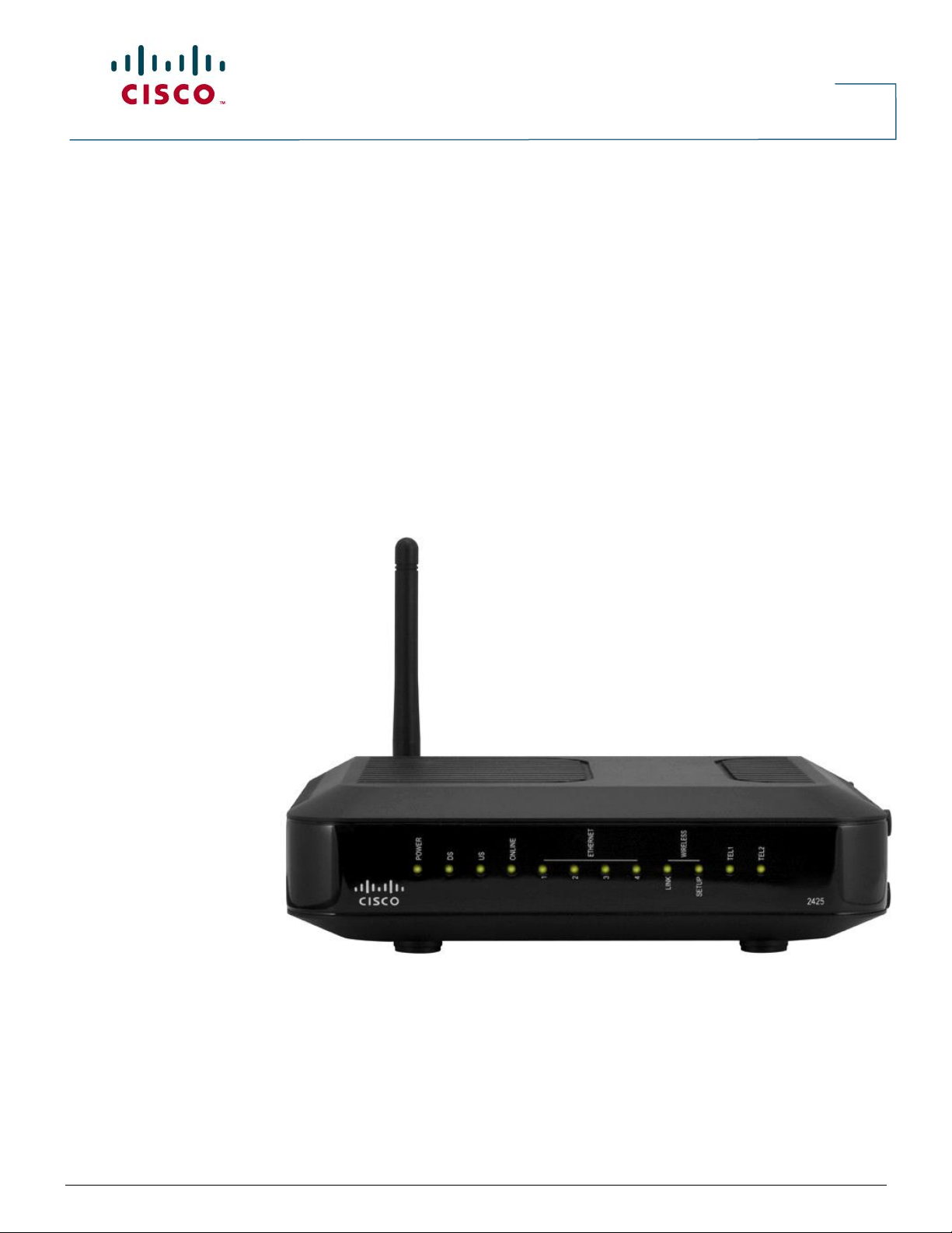
Cisco Model EPC2425 EuroDOCSIS 2.0 Wireless
Residential Gateway with Embedded Digital Voice Adapter
The Cisco® Model EPC2425 EuroDOCSIS 2.0 Wireless Residential Gateway with
Embedded Digital Voice Adapter (EPC2425) is a high performance home gateway that
combines a cable modem, two-line digital voice adapter, router and wireless access point
in a single device providing a cost-effective voice and networking solution for both the
home and small office.
The EPC2425 has been designed to meet EuroPacketCable™ 1.5 and EuroDOCSIS™ 2.0
specifications. In addition, the EPC2425 is fully backward compatible for use on both EuroDOCSIS
1.1 and EuroDOCSIS 1.0 networks.
Figure 1. Model EPC2425 EuroDOCSIS 2.0 Wireless Residential Gateway with Embedded Digital Voice
Adapter
Designed for the active digital home or office, the EPC2425’s integrated router features a Dynamic
Host Configuration Protocol (DHCP) server, Network Address and Port Translation (NAT/NAPT)
and a Stateful Packet Inspection (SPI) firewall. These features allow the user to share a single
high-speed public Internet connection as well as share files and folders between devices within the
home network by attaching multiple wired and wireless devices in your home or office to the
wireless residential gateway.
Page 2

Data Sheet
© 2010 Cisco and/or its affiliates. All rights reserved. This document is Cisco Public Information. Page 2 of 8
Consumer friendly features like Wireless Protected Setup (WPS) and user configured Parental
Control can protect the home network from unwelcome intruders and family members from access
to undesirable websites.
Features
●
Compliant with EuroDOCSIS 2.0, 1.1, and 1.0 standards along with EuroPacketCable
specifications to deliver high-end performance and reliability
●
High performance broadband Internet connectivity to energize your online experience
●
Two-line embedded digital voice adapter for wired telephony service
●
Four 10/100BASE-T Ethernet ports to provide wired connectivity
●
802.11g Wireless Access Point with 4 service set identifiers (SSIDs)
●
Wireless Protected Setup (WPS), including a push button switch to activate WPS for
simplified and secure wireless setup
●
Two RJ-11 telephony ports for connecting to in-home wiring or directly to conventional
telephones or fax machines
●
Dual antenna design - one internal and one detachable external
●
User configurable Parental Control blocks access to undesirable Internet sites
●
Advanced firewall technology deters hackers and protects the home network from
unauthorized access
●
Attractive compact design that allows for vertical, horizontal, or wall-mounted operation
●
TR-068 compliant color-coded interface ports and corresponding cables simplify installation
and setup
●
DOCSIS-5 compliant LED labeling and behavior provides a user and technician friendly
method to check operational status and act as a troubleshooting tool
●
Allows automatic software upgrades by your service provider
Page 3
Data Sheet
© 2010 Cisco and/or its affiliates. All rights reserved. This document is Cisco Public Information. Page 3 of 8
Feature
Description
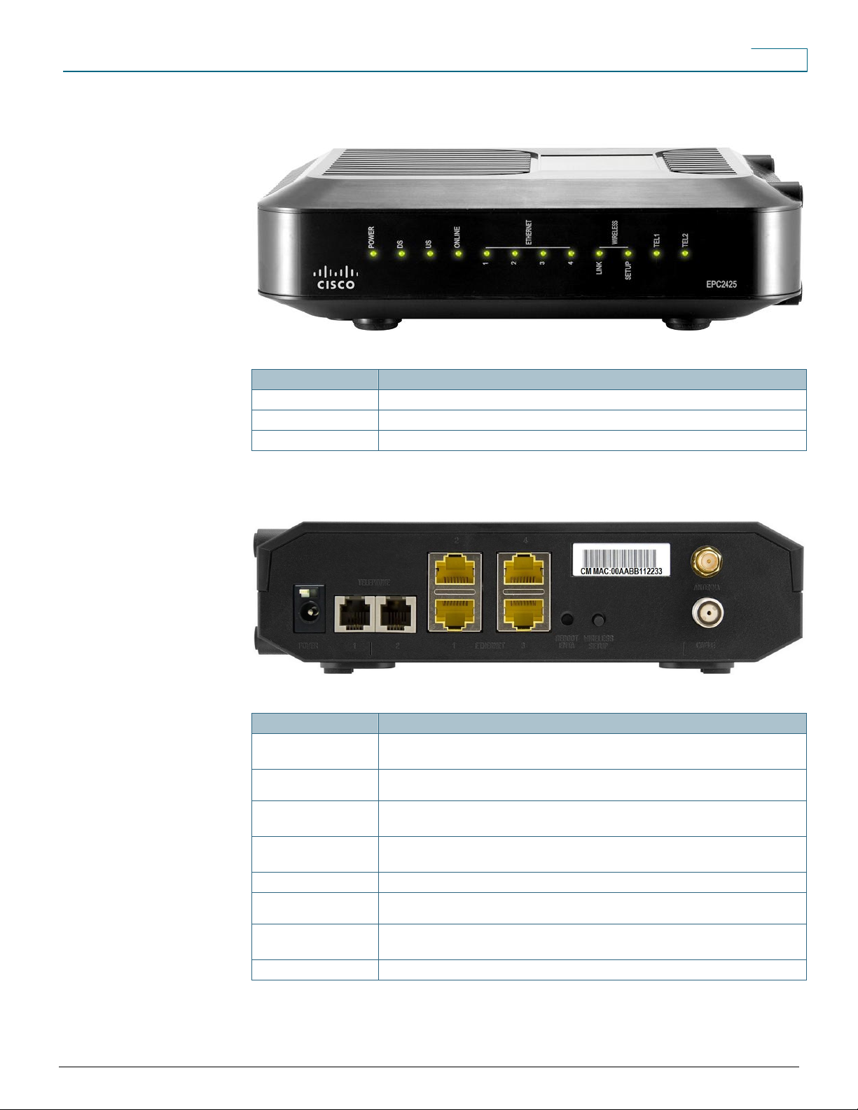
Indicators
Power, DS, US, Online, Ethernet, Wireless Link, Wireless Setup, Tel1, Tel2
Color
Black, black lens, silver text
Branding
Cisco and model number
Feature
Description
Power
Connector Color: Black
Connects the wireless home gateway to the DC output of the AC power adapter
Power Switch
Turns power on and off to the device (power switch provided on all products carrying the CE
mark)
Telephone 1 and 2
Color: Gray
RJ-11 telephone ports connect to home telephone wiring and to conventional telephones or fax
machines
Ethernet (1 – 4)
Connector Color: Yellow
Four RJ-45 Ethernet ports connect to the Ethernet port on your PC or your home network
Reboot EMTA
Power cycles the EMTA
Wireless Setup
Activates Wi-Fi Protected Setup (WPS), which allows you to add wireless devices to the wireless
network of the residential gateway
Cable
Connector Color: White
F-connector connects to an active cable signal from your service provider
Antenna (not shown)
Provides a communication connection for the built-in WAP
Figure 2. Model EPC2425 Front Panel (image may vary from actual product and specification)
Table 1. Front Panel Features
Figure 3. Model EPC2425 Back Panel (image may vary from actual product and specification)
Table 2. Back Panel Connections
Page 4

Data Sheet
© 2010 Cisco and/or its affiliates. All rights reserved. This document is Cisco Public Information. Page 4 of 8
Specification
Value
Voice Specifications
Call Signaling Protocol
●
MGCP/NCS including configurable IPSec encryption
●
Configurable to support RFC2833 event signaling
●
Supports Bell103 detection: Improves alarm panel and Point of Sale (POS) interoperability
by optimizing DSP for Bell103 protocol
●
Software upgradeable to support Session Initiation Protocol (SIP)
●
The following SIP standards are supported
◦ RFC 2617 HTTP Authentication: Basic and Digest Access Authentication
◦ RFC 2976 The SIP INFO Method
◦ RFC 3261 SIP: Session Initiation Protocol
◦ RFC 3262 Reliability of Provisional Responses in Session Initiation Protocol (SIP)
◦ RFC 3263 Session Initiation Protocol (SIP): Locating SIP Servers
◦ RFC 3264 An Offer/Answer Model with Session Description Protocol (SDP)
◦ RFC 3265 Session Initiation Protocol (SIP)-Specific Event Notification
◦ RFC 3420 Internet Media Type message/sipfrag
◦ RFC 3428 Session Initiation Protocol (SIP) Extension for Instant Messaging
◦ RFC 3515 The Session Initiation Protocol (SIP) Refer Method
◦ RFC 3842 A Message Summary and Message Waiting Indication Event
●
Package for the Session Initiation Protocol (SIP)
◦ RFC 3892 The Session Initiation Protocol (SIP) Referred-By Mechanism
◦ RFC 3903 Session Initiation Protocol (SIP) Extension for Event State Publication
◦ Draft-ietf-mmusic-sdp-new-24 SDP: Session Description Protocol (Replacement for RFC
2327)
◦ Draft-ietf-sipping-cc-transfer-01 Session Initiation Protocol Call Control – Transfer
◦ Draft-ietf-sip-session-timer-08 The SIP Session Timer
◦ Draft-ietf-sipping-realtimefax-01 SIP Support for Real-time Fax: Call Flow
●
Examples and Best Current Practices
◦ Draft-ietf-mmusic-sdescription-09 Session Description Protocol Security
◦ Descriptions for Media Streams
◦ Draft-ietf-sip-replaces-02 The Session Initiation Protocol (SIP) "Replaces" Header
Provisioning Modes
●
Full PacketCable secure provisioning
●
Kerberos support with NVRAM ticket caching
●
Configurable PacketCable-lite (MTA config file provisioning without security)
●
Configurable for non-PacketCable (MTA configuration using DOCSIS config file)
CODECs
Standard: G.711, T.38 Fax Relay, iLBC and BV16
Software upgradeable to support other CODEC combinations including:
●
G.711 and G.728
●
G.711 and G.729
●
G.711 and G.729 a/e
●
G.711 and BV16 and BV32 (High fidelity – near CD quality)
●
G.711 and G.723
●
G.711 and G.726
CODEC Packetization
Intervals
10, 20, and 30 mS
CODEC Synchronization
CODEC synchronization to UGS time clock allows slip-free end-to-end sync to PSTN clock
(minimizes frame slips that can cause Fax/Analog Modem call failures)
CODEC Encryption
Configurable to support AES-128 encryption or no encryption modes
Hearing Impaired Services
Support
TDD support including detection of V.18 including Annex A
Fax and Analog Modem
support
DSP based Modem/Fax Tone detection and support for Voice Band Data Mode with autoCODEC negotiation and auto-control of echo canceller, jitter buffer, and VAD
Jitter Buffer Support
Adaptive dynamically controlled
Latency Control
Configurable min / max jitter buffer size
Product Specifications
Table 3. Product Specifications
Page 5

Data Sheet
© 2010 Cisco and/or its affiliates. All rights reserved. This document is Cisco Public Information. Page 5 of 8
Specification
Value
Voice Specifications
Audio Gain Levels
Independently Configurable Tx and Rx audio gains
Silence Suppression
Configurable VAD with comfort noise generation
Packet Loss Concealment
ANSI T1.521-1999
Call Connection Quality
Monitoring
RTCP, RFC1889, RFC1890, SNMP MIB for last call quality statistics
Dialing Modes
DTMF and configurable pulse dial support
DTMF Relay
RFC2833 including fast (40mS) DTMF Relay for alarm system signaling compatibility
Layer 2 Quality of Service
●
Full PacketCable secure DQOS with GateID including UGS and UGS/AD
●
DQOS Lite support including UGS and UGS/AD
Layer 3 Quality of Service
Configurable DiffServe/TOS support for Signaling, RTP, and RTCP flows
Payload Header
Suppression (PHS)
Supported for RTP and RTCP packet flows to reduce per-call network bandwidth.
Advanced support for Dynamic Payload Header Suppression using Propane Technology.
Management
SNMPv3, SNMPv2, Telnet with configurable user ID and password, internal log, and external
Syslog support
Echo Cancellation
G.168 with extended echo tail support
Call Feature Support
●
Caller ID
●
Call Waiting with Caller ID
●
Cancel Call Waiting
●
Call Conferencing (3-way calls)
●
Configurable hook flash support
●
Distinctive Ringing (Configurable for up to 11 ring patterns per phone line)
●
Ring Splash
●
Stutter Dial Tone
●
Off hook warning tone
●
Open Switch Interval support to enhance answering machine compatibility
●
Configurable star codes
●
Euro/US hook-flash type
●
Call transfer
●
Message Waiting Indicator
●
Warm Line
●
Call Forwarding Unconditional
●
Call Forwarding on Busy
●
Call Forwarding No Answer
●
Call return
●
Redial Call
●
Automatic redial
●
Other call features available with compliant CMS or gateway
Telephone Ring Loading
Full 5 REN support on each phone line (10 REN total)
Ring Signal
Configurable balanced ring with configurable DC offset
Max Phone Line Distance
Supports up to 1000 ft of AWG26 wire (0.4mm) on each phone line. Supports operation with
typical in-home telephone wiring
Country-Specific
Telephone Parameters
Supported
United States,United Kingdom, Germany, France, Belgium, Netherlands, Finland, Italy,
Switzerland, Sweden, Denmark, Brazil, ETSI 101 909-18
RF Downstream
Frequency Range
108 to 930 MHz
Demodulation
64 or 256 QAM
Maximum Data Rate
41.4 Mbps for 64 QAM
55.2 Mbps for 256 QAM
Bandwidth
8 MHz
Operating Level Range
43 to 73 dBµV for 64 QAM
47 to 77 dBµV for 256 QAM
Input Impedance
75 ohms
Page 6

Data Sheet
© 2010 Cisco and/or its affiliates. All rights reserved. This document is Cisco Public Information. Page 6 of 8
Specification
Value
RF Upstream
Frequency Range
5 to 65 MHz
Modulation
QPSK
8 QAM
16 QAM
64 QAM
128 QAM TCM
Maximum Data Rate
5.12 Mbps for QPSK
10.2 Mbps for 16 QAM
30.0 Mbps for A-TDMA and SCDMA
Bandwidth
200 kHz to 6.4 MHz
Operating Level Range
(all values +/- 0.5 dBµV)
TDMA
SCDMA
QPSK +68 to +118 dBµV
8QAM +68 to +115 dBµV
16QAM +68 to +115 dBµV
32QAM +68 to +114 dBµV
64QAM +68 to +114 dBµV
QPSK +68 to +113 dBµV
8QAM +68 to +113 dBµV
16QAM +68 to +113 dBµV
32QAM +68 to +113 dBµV
64QAM +68 to +113 dBµV
128QAM +68 to +113 dBµV
Output Impedance
75 ohms
Wireless Access Point
Frequency Range
2.412~2.472 GHz, 13 Channel (Europe; CE/ETSI)
Modulation
DSSS (Direct Sequence Spread Spectrum)
Data Rate:
802.11g
54 Mbps with Auto Fall-Back
Security
WPA2, WPA and 64/128-bit WEP
Transmit Power
14 dBm (typical for 802.11g)
Antenna System
One (1) external, detachable
One (1) internal
Other
Input Voltage
12 VDC
Power Consumption
(Modem Module)
6 watts
Data Ports
Ethernet 10/100BASE-T (Auto-sensing with Auto-MDIX)
RJ-45 Ethernet (4)
RF
Female “F” type
Mechanical
Dimensions (W x D x H)
(approximate)
Not including “F” connector:
17.7 cm x 14.5 cm x 5.0 cm (6 15/16 in. x 5 11/16 in. x 2 15/16 in.)
Including “F” connector and wireless antenna:
17.7 cm x 15.5 cm x 5.0 cm (6 15/16 in. x 6 in. x 2 15/16 in.)
Weight (approximate)
0.39 kg (13.7 oz)
Operating Temperature
0˚ to 40˚C (32˚ to 104˚F)
Operating Humidity
0 to 90% RH non-condensing
Storage Temperature
-20˚ to 60˚C (-4˚ to 140˚F)
Page 7

Data Sheet
© 2010 Cisco and/or its affiliates. All rights reserved. This document is Cisco Public Information. Page 7 of 8
Specification
Value
Standards and Approvals
Designed to Comply with
the Following Standards
Euro-PacketCable 1.5
EuroDOCSIS 2.0, EuroDOCSIS 1.1, EuroDOCSIS 1.0
IEEE 802.11g
WEP, WPA, and WPA2
WMM, WPS
Regulatory and Safety
Approvals
As required per country where the EPC2425 will be used
Model
Description
Part Number
International Configuration – PAL/NTSC
Model EPC2425
EPC2425 EuroDOCSIS 2.0 Wireless Residential Gateway with
Embedded Digital Voice Adapter. Includes:
●
International tuning plan
●
230 VAC / 50 Hz, 15 VDC / 1 A desk top linear power supply, Europe
●
Ethernet cable
●
CD-ROM containing user guide
Europe
4027678
Model EPC2425
EPC2425 EuroDOCSIS 2.0 Wireless Residential Gateway with
Embedded Digital Voice Adapter. Includes:
●
North American tuning plan
●
100-240 VAC / 50-60 Hz, 15 VDC / 1 A wall-mount switching
regulated power supply, Europe
●
Ethernet cable
●
CD-ROM containing user guide
Europe (Customer-specific configuration)
4028605
Model EPC2425
EPC2425 EuroDOCSIS 2.0 Wireless Residential Gateway with
Embedded Digital Voice Adapter. Includes:
●
North American tuning plan
●
100-240 VAC / 50-60 Hz, 15 VDC / 1 A wall-mount switching
regulated power supply, Europe
●
Ethernet cable
●
CD-ROM containing user guide
Europe (Customer-specific configuration)
4030556
Model EPC2425
EPC2425 EuroDOCSIS 2.0 Wireless Residential Gateway with
Embedded Digital Voice Adapter. Includes:
●
North American tuning plan
●
100-240 VAC / 50-60 Hz, 15 VDC / 1 A wall-mount switching
regulated power supply, Europe
●
Ethernet cable
●
CD-ROM containing user guide
Europe (Customer-specific configuration)
4030557
Model EPC2425
EPC2425 EuroDOCSIS 2.0 Wireless Residential Gateway with
Embedded Digital Voice Adapter. Includes:
●
North American tuning plan
●
230 VAC / 50-60 Hz, 15 VDC / 1 A wall-mount linear switching power
supply, Europe
●
Ethernet cable
●
CD-ROM containing user guide
Sweden (Customer-specific configuration)
4028604
Ordering Information
Table 4. Ordering Information
Page 8

Data Sheet
© 2010 Cisco and/or its affiliates. All rights reserved. This document is Cisco Public Information. Page 8 of 8
Description
Part Number
Power Supplies
Class 2 Linear Switching
230-240 VAC / 50-60 Hz, 12 VDC /1 A wall-mount linear switching power supply with Euro style
connector
4020995
Class 2 Switching Regulated
100-240 VAC / 50-60 Hz, 12 VDC /1 A wall-mount linear switching power supply with Euro style
connector
4022057
CD-ROM
CD-ROM with User Guide
7016771
Cisco and the Cisco logo are trademarks or registered trademarks of Cisco and/or its affiliates in the U.S. and
other countries. A listing of Cisco's trademarks can be found at www.cisco.com/go/trademarks
EuroDOCSIS and EuroPacketCable are trademarks of Cable Television Laboratories, Inc.
Other third party trademarks mentioned are the property of their respective owners.
The use of the word partner does not imply a partnership relationship between Cisco and any other company
(1009R).
Specifications and product availability are subject to change without notice.
2008, 2010 Cisco and/or its affiliates. All rights reserved.
Cisco Systems, Inc.
800 722-2009 or 678 277-1120 Part Number 7016661 Rev B
www.cisco.com November 2010
Replacement Components
Table 5. Replacement Components
 Loading...