

Page 1

FINAL DRAFT - CISCO CONFIDENTIAL
Cisco ONS 15216 EDFA2
Operations Guide
Product and Software Release 2.3
August 2003
Corporate Headquarters
Cisco Systems, Inc.
170 West Tasman Drive
San Jose, CA 95134-1706
USA
http://www.cisco.com
Tel: 408 526-4000
800 553-NETS (6387)
Fax: 408 526-4100
Text Part Number: 78-16033-01
Page 2

FINAL DRAFT - CISCO CONFIDENTIAL
THE SPECIFICATIONS AND INFORMATION REGARDING THE PRODUCTS IN THIS MANUAL ARE SUBJECT TO CHANGE WITHOUT NOTICE. ALL
STATEMENTS, INFORMATION, AND RECOMMENDATIONS IN THIS MANUAL ARE BELIEVED TO BE ACCURATE BUT ARE PRESENTED WITHOUT
WARRANTY OF ANY KIND, EXPRESS OR IMPLIED. USERS MUST TAKE FULL RESPONSIBILITY FOR THEIR APPLICATION OF ANY PRODUCTS.
THE SOFTWARE LICENSE AND LIMITED WARRANTY FOR THE ACCOMPANYING PRODUCT ARE SET FORTH IN THE INFORMATION PACKET THAT
SHIPPED WITH THE PRODUCT AND ARE INCORPORATED HEREIN BY THIS REFERENCE. IF YOU ARE UNABLE TO LOCATE THE SOFTWARE LICENSE
OR LIMITED WARRANTY, CONTACT YOUR CISCO REPRESENTATIVE FOR A COPY.
The following information is for FCC compliance of Class A devices: This equipment has been tested and found to comply with the limits for a Class A digital device, pursuant
to part 15 of the FCC rules. These limits are designed to provide reasonable protection against harmful interference when the equipment is operated in a commercial
environment. This equipment generates, uses, and can radiate radio-frequency energy and, if not installed and used in accordance with the instruction manual, may cause
harmful interference to radio communications. Operation of this equipment in a residential area is likely to cause harmful interference, in which case users will be required
to correct the interference at their own expense.
The following information is for FCC compliance of Class B devices: The equipment described in this manual generates and may radiate radio-frequency energy. If it is not
installed in accordance with Cisco’s installation instructions, it may cause interference with radio and television reception. This equipment has been tested and found to
comply with the limits for a Class B digital device in accordance with the specifications in part 15 of the FCC rules. These specifications are designed to provide reasonable
protection against such interference in a residential installation. However, there is no guarantee that interference will not occur in a particular installation.
Modifying the equipment without Cisco’s written authorization may result in the equipment no longer complying with FCC requirements for Class A or Class B digital
devices. In that event, your right to use the equipment may be limited by FCC regulations, and you may be required to correct any interference to radio or television
communications at your own expense.
You can determine whether your equipment is causing interference by turning it off. If the interference stops, it was probably caused by the Cisco equipment or one of its
peripheral devices. If the equipment causes interference to radio or television reception, try to correct the interference by using one or more of the following measures:
• Turn the television or radio antenna until the interference stops.
• Move the equipment to one side or the other of the television or radio.
• Move the equipment farther away from the television or radio.
• Plug the equipment into an outlet that is on a different circuit from the television or radio. (That is, make certain the equipment and the television or radio are on circuits
controlled by different circuit breakers or fuses.)
Modifications to this product not authorized by Cisco Systems, Inc. could void the FCC approval and negate your authority to operate the product.
The Cisco implementation of TCP header compression is an adaptation of a program developed by the University of California, Berkeley (UCB) as part of UCB’s public
domain version of the UNIX operating system. All rights reserved. Copyright © 1981, Regents of the University of California.
NOTWITHSTANDING ANY OTHER WARRANTY HEREIN, ALL DOCUMENT FILES AND SOFTWARE OF THESE SUPPLIERS ARE PROVIDED “AS IS” WITH
ALL FAULTS. CISCO AND THE ABOVE-NAMED SUPPLIERS DISCLAIM ALL WARRANTIES, EXPRESSED OR IMPLIED, INCLUDING, WITHOUT
LIMITATION, THOSE OF MERCHANTABILITY, FITNESS FOR A PARTICULAR PURPOSE AND NONINFRINGEMENT OR ARISING FROM A COURSE OF
DEALING, USAGE, OR TRADE PRACTICE.
IN NO EVENT SHALL CISCO OR ITS SUPPLIERS BE LIABLE FOR ANY INDIRECT, SPECIAL, CONSEQUENTIAL, OR INCIDENTAL DAMAGES, INCLUDING,
WITHOUT LIMITATION, LOST PROFITS OR LOSS OR DAMAGE TO DATA ARISING OUT OF THE USE OR INABILITY TO USE THIS MANUAL, EVEN IF CISCO
OR ITS SUPPLIERS HAVE BEEN ADVISED OF THE POSSIBILITY OF SUCH DAMAGES.
CCIP, CCSP, the Cisco Arrow logo, the Cisco Powered Network mark, the Cisco Systems Verified logo, Cisco Unity, Follow Me Browsing, FormShare, iQ Net Readiness
Scorecard, Networking Academy, and ScriptShare are trademarks of Cisco Systems, Inc.; Changing the Way We Work, Live, Play, and Learn, The Fastest Way to Increase
Your Internet Quotient, and iQuick Study are service marks of Cisco Systems, Inc.; and Aironet, ASIST, BPX, Catalyst, CCDA, CCDP, CCIE, CCNA, CCNP, Cisco, the
Cisco Certified Internetwork Expert logo, Cisco IOS, the Cisco IOS logo, Cisco Press, Cisco Systems, Cisco Systems Capital, the Cisco Systems logo, Empowering the
Internet Generation, Enterprise/Solver, EtherChannel, EtherSwitch, Fast Step, GigaStack, Internet Quotient, IOS, IP/TV, iQ Expertise, the iQ logo, LightStream, MGX,
MICA, the Networkers l ogo, Network Registrar, Packet, PIX, Post-Routing, Pre-Routing, RateMUX, Registrar, SlideCast, SMARTnet, StrataView Plus, Stratm, SwitchProbe,
TeleRouter, TransPath, and VCO are registered trademarks of Cisco Systems, Inc. and/or its affiliates in the U.S. and certain other countries.
All other trademarks mentioned in this document or Web site are the property of their respective owners. The use of the word partner does not imply a partnership relationship
between Cisco and any other company. (0303R)
Cisco ONS 15216 EDFA2 Operations Guide
Copyright © 2003, Cisco Systems, Inc.
All rights reserved.
Page 3

FINAL DRAFT - CISCO CONFIDENTIAL
Preface xix
Obtaining Documentation xix
Cisco.com xix
Optical Networking Product Documentation CD-ROM xix
Ordering Documentation xix
Documentation Feedback xx
Obtaining Technical Assistance xx
Cisco.com xx
Technical Assistance Center xxi
Obtaining Additional Publications and Information xxii
CONTENTS
CHAPTER
CHAPTER
1 Applications 1-1
1.1 Bandwidth On Demand 1-1
1.2 Wavelength Protection Switching 1-1
1.3 Key Features 1-2
1.3.1 Constant Gain 1-3
1.3.2 Gain Flattening 1-3
1.3.3 Transient Suppression 1-4
1.3.4 Low Noise 1-4
1.3.5 SNMP MIBs 1-4
1.3.6 TL1 1-4
2 Technical Specifications 2-1
2.1 Optical Specifications 2-1
2.1.1 Maximum Input Power 2-2
2.1.2 Channel Loading 2-2
2.2 Electrical Specifications 2-3
2.3 Mechanical Specifications 2-4
2.4 External Features 2-4
CHAPTER
78-16033-01
2.5 Front Panel 2-5
3 Installation 3-1
3.1 Introduction 3-1
Cisco ONS 15216 EDFA2 Operations Guide
iii
Page 4

Contents
FINAL DRAFT - CISCO CONFIDENTIAL
3.2 Standard Precautions 3-1
3.3 Placement and Power Connection 3-1
3.3.1 General Rack Considerations 3-1
3.3.2 Rack Installation and Power Supply Connection Procedures 3-2
3.4 SC/UPC Optical Ports 3-3
3.4.1 Safety Requirements 3-3
3.4.2 Optical Connection Procedure 3-3
3.4.3 Optical Amplification Operation Verification Procedure 3-4
3.5 Communications 3-5
3.5.1 Alarm Out Relay Interface (RJ-45) 3-5
3.5.2 Alarm LEDs 3-6
3.5.3 Serial Interface (EIA/TIA-232) Communication 3-7
3.5.4 Serial Interface Remote Communication via Modem 3-11
3.5.5 LAN Interface (Ethernet) 3-14
CHAPTER
4 Provisioning Using ASH and SNMP 4-1
4.1 Log In via RS-232 (EIA/TIA-232) Port Using HyperTerminal 4-1
4.2 Set IP Address 4-3
4.3 Log In via LAN Port Using Telnet (Optional) 4-3
4.4 Set Date and Time 4-4
4.5 Set Power Bus Mode (Simplex or Duplex) 4-4
4.6 Verify Amplifier Operational Status 4-4
4.7 Set Gain 4-5
4.8 Set Alarm Thresholds 4-5
4.9 Set Password 4-10
4.10 Add Users 4-11
4.11 Save Changes 4-11
4.12 Log Off 4-12
4.13 Back Up System Configuration 4-12
4.14 Restore System Configuration 4-13
4.15 Recover Default Password 4-14
CHAPTER
iv
5 SNMP MIB Installation and Configuration 5-1
5.1 SNMP Overview 5-1
5.1.1 SNMP Components 5-1
5.1.2 ONS 15216 EDFA2 SNMP Elements 5-2
5.1.3 SNMP MIBs and Message Types 5-3
Cisco ONS 15216 EDFA2 Operations Guide
78-16033-01
Page 5

FINAL DRAFT - CISCO CONFIDENTIAL
5.1.4 Command Syntax Using the SNMP Agent 5-4
5.2 Enabling SNMP Remote Management Community Strings 5-5
5.2.1 Creating a View 5-6
5.2.2 Creating a Community Entry 5-7
5.3 Setup for CTM Access 5-10
5.4 Tables and Groups 5-11
5.4.1 CfgGroup Table 5-12
5.4.2 PumpCfgEntry Table 5-14
5.4.3 OverallStatusGroup Table 5-16
5.4.4 OverallControl Table 5-18
5.4.5 PumpStatusEntry Table 5-18
5.4.6 AlarmEntry Table 5-19
5.4.7 OpGroup Table 5-20
5.4.8 VersionGroup Table 5-21
5.5 Setting Up Traps 5-21
5.5.1 Display Trap Command 5-22
5.5.2 Set Trap Command 5-23
5.5.3 Set Agent Trap Enable 5-23
5.5.4 Get Agent Trap Enable 5-24
Contents
CHAPTER
5.6 Retrieving Information 5-24
5.6.1 IP Address 5-24
5.6.2 Date and Time 5-25
5.6.3 Power Gain 5-26
5.6.4 Case Temperature 5-27
5.6.5 Power Bus 5-29
5.6.6 Input Power (Signal) 5-30
5.6.7 Output Power 5-31
5.6.8 Database Backup and Restore 5-34
5.6.9 Alarm Entry 5-36
5.7 Summary of SNMP Alarms 5-37
6 ASH Commands 6-1
6.1 Summary of Security Permissions for ASH Commands 6-1
6.2 Configuration Commands 6-6
6.2.1 srom cfg boot display Command 6-6
6.2.2 srom cfg boot modify Command 6-7
6.2.3 srom cfg ip display Command 6-7
6.2.4 srom cfg ip modify Command 6-8
6.2.5 pdm busmode display Command 6-8
78-16033-01
Cisco ONS 15216 EDFA2 Operations Guide
v
Page 6

Contents
FINAL DRAFT - CISCO CONFIDENTIAL
6.2.6 pdm busmode modify Command 6-9
6.2.7 pdm cfg threshold bus display Command 6-9
6.2.8 pdm cfg threshold bus modify Command 6-9
6.2.9 gain gain display Command 6-9
6.2.10 gain gain modify Command 6-10
6.2.11 voa power input display Command 6-10
6.3 Administrative Commands 6-10
6.3.1 clear Command 6-11
6.3.2 exit Command 6-11
6.3.3 help Command 6-11
6.3.4 history Command 6-11
6.3.5 login and logoff Commands 6-12
6.3.6 processor reset Command 6-12
6.4 Shell Commands 6-12
6.4.1 shell lines set Command 6-13
6.4.2 shell more enable and disable Commands 6-13
6.4.3 shell status display Command 6-13
6.4.4 shell type modify Command 6-13
6.5 Flash File System Commands 6-14
6.5.1 ffs file list Command 6-14
6.6 SNMP Commands 6-15
6.6.1 snmp attribute get Command 6-15
6.6.2 snmp attribute list Command 6-16
6.6.3 snmp attribute set Command 6-17
6.6.4 snmp mib display Command 6-17
6.6.5 snmp mib get Command 6-18
6.6.6 snmp mib list Command 6-18
6.6.7 snmp row display Command 6-19
6.6.8 snmp row get Command 6-20
6.6.9 snmp row set Command 6-20
6.6.10 snmp subtree display Command 6-21
6.6.11 snmp subtree get Command 6-21
6.6.12 snmp subtree list Command 6-22
6.6.13 snmp table display Command 6-23
6.6.14 snmp table get Command 6-24
6.6.15 snmp table list Command 6-24
6.6.16 snmp tree attribute list Command 6-25
vi
6.7 User Commands 6-25
6.7.1 user entry create Command 6-26
Cisco ONS 15216 EDFA2 Operations Guide
78-16033-01
Page 7

FINAL DRAFT - CISCO CONFIDENTIAL
6.7.2 user entry edit Command 6-26
6.7.3 user entry delete Command 6-27
6.7.4 user file display and user name display Commands 6-27
6.7.5 user inactivity modify and user inactivity display Commands 6-28
6.7.6 user passwd set Command 6-28
6.7.7 user active list Command 6-29
6.7.8 user active message send Command 6-29
6.8 Manufacturing Information Access Commands 6-30
6.8.1 snmp table display local entPhysicalEntry Command 6-30
6.8.2 snmp table display local cerent15216EdfaCommTrapEntry Command 6-30
6.9 Restore Commands 6-31
6.9.1 backup system Command 6-31
6.9.2 restore system Command 6-31
6.10 Manufacturer Mode 6-32
6.10.1 manufacturer restore defaults passwords Command 6-32
6.10.2 manufacturer restore defaults all Command 6-32
Contents
CHAPTER
CHAPTER
7 FTP Command Line 7-1
7.1 FTP Command Line 7-1
7.1.1 Example of FTP from a Remote Server 7-1
7.1.2 Example of FTP to a Remote Server 7-2
7.2 FTP Commands 7-3
8 Provisioning Using TL1 8-1
8.1 Log In via RS-232 (EIA/TIA-232) Port Using HyperTerminal 8-1
8.2 Set IP Address 8-3
8.3 Log In via LAN Port Using Telnet (Optional) 8-3
8.4 Set Date and Time 8-4
8.5 Set Power Bus Mode (Simplex or Duplex) 8-4
8.6 Verify Amplifier Operational Status 8-4
8.7 Set Gain 8-5
8.8 Set Alarm Thresholds 8-5
8.9 Set Password 8-10
8.10 Add Users 8-11
78-16033-01
8.11 Log Off 8-11
8.12 Back Up System Configuration 8-11
8.13 Restore System Configuration 8-12
Cisco ONS 15216 EDFA2 Operations Guide
vii
Page 8

Contents
FINAL DRAFT - CISCO CONFIDENTIAL
CHAPTER
9 TL1 Commands 9-1
9.1 Introduction 9-1
9.2 Connection to the ONS 15216 EDFA2 9-1
9.3 Explanation of Command Parameters 9-1
9.3.1 Source Identifier (sid) and Target Identifier (tid) 9-1
9.3.2 Command Code Modifier (ccm) 9-2
9.3.3 Access Identifier (aid) 9-2
9.3.4 Correlation Tag (ctag) 9-2
9.4 Notation 9-2
9.5 Summary of Autonomous Alarms and Messages 9-3
9.6 Summary of Security Permissions for TL1 Commands 9-6
9.7 TL1 Commands and Autonomous Messages 9-9
9.7.1 ACT-USER 9-9
9.7.2 ALW-MSG-ALL 9-9
9.7.3 APPLY 9-11
9.7.4 CANC-USER 9-12
9.7.5 COPY-RFILE 9-12
9.7.6 CPY-MEM 9-14
9.7.7 DLT-RFILE 9-15
9.7.8 DLT-USER-SECU 9-16
9.7.9 ED-DAT 9-16
9.7.10 ED-DWDM 9-17
9.7.11 ED-ENV 9-18
9.7.12 ED-NE-GEN 9-19
9.7.13 ED-PID 9-20
9.7.14 ED-USER-SECU 9-21
9.7.15 ENT-USER-SECU 9-21
9.7.16 INH-MSG-ALL 9-22
9.7.17 INIT-SYS 9-25
9.7.18 REPT ALM DWDM 9-25
9.7.19 REPT ALM ENV 9-27
9.7.20 REPT ALM EQPT 9-28
9.7.21 REPT EVT DWDM / REPT EVT ENV / REPT EVT EQPT 9-30
9.7.22 REPT EVT FXFR 9-32
9.7.23 RTRV-ALM-ALL 9-33
9.7.24 RTRV-ALM-DWDM 9-35
9.7.25 RTRV-ALM-ENV 9-37
9.7.26 RTRV-ALM-EQPT 9-38
9.7.27 RTRV-AO 9-40
viii
Cisco ONS 15216 EDFA2 Operations Guide
78-16033-01
Page 9

FINAL DRAFT - CISCO CONFIDENTIAL
9.7.28 RTRV-COND-ALL 9-41
9.7.29 RTRV-COND-DWDM 9-43
9.7.30 RTRV-COND-ENV 9-44
9.7.31 RTRV-COND-EQPT 9-46
9.7.32 RTRV-DFLT-SECU 9-47
9.7.33 RTRV-DWDM 9-48
9.7.34 RTRV-ENV 9-50
9.7.35 RTRV-HDR 9-51
9.7.36 RTRV-INV 9-51
9.7.37 RTRV-NE-GEN 9-52
9.7.38 RTRV-RFILE 9-54
9.7.39 RTRV-TH-DWDM 9-55
9.7.40 RTRV-TH-ENV 9-56
9.7.41 RTRV-TH-EQPT 9-57
9.7.42 RTRV-TOD 9-59
9.7.43 RTRV-USER-SECU 9-60
9.7.44 SET-ATTR-SECUDFLT 9-60
9.7.45 SET-TH-DWDM 9-61
9.7.46 SET-TH-ENV 9-62
9.7.47 SET-TH-EQPT 9-63
9.7.48 STA-LOCL-RST 9-64
Contents
CHAPTER
10 Troubleshooting 1
10.1 Alarm Indicators 2
10.1.1 LEDs and Office Alarms 2
10.1.2 Optical Alarms 4
10.1.3 Equipment Alarms 6
10.1.4 Environmental Alarms 7
10.2 Troubleshooting Typical Scenarios 7
10.2.1 No Output Power after Adjusting Gain Settings 7
10.2.2 2.0.1 to 2.2.1 Upgrade Attempt 8
10.2.3 Image File Download Incomplete 8
10.2.4 Boot Up Failure 8
10.2.5 No Response from RS-232 Port 9
10.2.6 No Response from LAN Port 9
10.2.7 LAN Port Activity LED Stays On 9
10.2.8 Lost Password 10
10.3 Status Information Needed by Cisco TAC 11
78-16033-01
Cisco ONS 15216 EDFA2 Operations Guide
ix
Page 10

Contents
FINAL DRAFT - CISCO CONFIDENTIAL
APPENDIX
A Regulatory Compliance and Safety Information A-1
Regulatory Compliance A-1
Translated Safety Warnings A-2
Warning Definition A-4
DC Power Supply Warning A-6
Installation Warning A-7
Power Cord Warning A-7
No On/Off Switch Warning A-8
SELV Circuit Warning A-9
Laser Radiation Warning A-10
Laser Beam Warning A-11
Power Cabling Warning A-11
Grounded Equipment Warning A-12
Ground Connection Warning A-13
Jewelry Removal Warning A-14
Qualified Personnel Warning A-15
Supply Circuit Warning A-15
Power Supply Wiring Warning A-16
Invisible Laser Radiation Warning A-17
Incorrect Connection Warning A-18
Ground Conductor Warning A-19
Voltages on DC-input Power Supply Terminals A-20
More Than One Power Supply A-21
Cisco ONS 15216 EDFA2 Rack Installation A-21
Exposed DC Power Wire Warning A-22
48 VDC Power System A-23
Chassis Power Connection A-24
Cisco ONS 15216 EDFA2 Temperature Requirement A-25
VCCI Compliance for Class B Equipment A-26
SELV-IEC 60950 DC Power Supply Warning A-26
Cisco ONS 15216 EDFA2 Power Circuit Overload Warning A-27
Product Disposal Warning A-28
Energy Hazard A-29
Unit Grounding Protection Warning A-30
DC Power Disconnection Warning A-31
Ground Wire Warning A-32
Declaration of Conformity with Regard to the Directives 73/23/EEC and 89/336/EEC as amended by
Directive 93/68/EEC
A-33
Declaration of Conformity to R&TTE Directive 1999/5/EEC for the European Community, Switzerland,
Norway, Iceland and Liechtenstein
A-34
Cisco ONS 15216 EDFA2 Operations Guide
x
78-16033-01
Page 11

FINAL DRAFT - CISCO CONFIDENTIAL
Class B EMC Warning A-35
Safety Requirements Warning A-35
Laser Radiation Warning A-36
Fiber Disconnect Sequence Warning A-37
Optical Connector Warning A-38
Optical Connector Disconnect Warning A-38
Eye Damage Warning A-39
Static Electricity Warning A-40
Connector Cleaning Warning A-41
Cable Connection Sequence Warning A-42
Module Removal Warning A-43
DC Power SELV Requirement Warning A-44
Reinforced Insulation Warning A-45
Power Supply Voltage Warning A-46
DC Power Supply Connection Warning A-46
Contents
I
NDEX
78-16033-01
Cisco ONS 15216 EDFA2 Operations Guide
xi
Page 12

Contents
FINAL DRAFT - CISCO CONFIDENTIAL
xii
Cisco ONS 15216 EDFA2 Operations Guide
78-16033-01
Page 13

FINAL DRAFT - CISCO CONFIDENTIAL
Figure 1-1 Wavelength Protection Switching 1-2
Figure 1-2 ONS 15216 EDFA2 Block Diagram 1-2
Figure 1-3 Gain Flattening Filter 1-3
Figure 2-1 ONS 15216 EDFA2 Dimensions 2-5
Figure 2-2 ONS 15216 EDFA2 Front Panel 2-5
Figure 3-1 ONS 15216 EDFA2 Optical Connections 3-4
Figure 3-2 HyperTerminal Connect To Dialog Box 3-8
Figure 3-3 HyperTerminal COM1 Properties Dialog Box 3-9
Figure 3-4 Optical Amplifier Properties Dialog Box (Connect To Tab) 3-9
Figure 3-5 Optical Amplifier Properties Dialog Box (Settings Tab) 3-10
Figure 3-6 HyperTerminal ASCII Setup Dialog Box 3-10
FIGURES
Figure 3-7 Remote Communication 3-11
Figure 3-8 DB-9 Pinout for RS-232 (EIA/TIA-232) Port 3-14
Figure 4-1 ONS 15216 EDFA2 Front Panel 4-6
Figure 5-1 SNMP Elements 5-2
Figure 5-2 SNMP Agent and MIB 5-3
Figure 8-1 ONS 15216 EDFA2 Front Panel 8-6
78-16033-01
Cisco ONS 15216 EDFA2 Operations Guide
xiii
Page 14

Figures
FINAL DRAFT - CISCO CONFIDENTIAL
xiv
Cisco ONS 15216 EDFA2 Operations Guide
78-16033-01
Page 15

FINAL DRAFT - CISCO CONFIDENTIAL
Table 2-1 ONS 15216 EDFA2 Optical Specifications 2-1
Table 2-2 Maximum Channel Power 2-2
Table 2-3 ONS 15216 EDFA2 Electrical Specifications 2-3
Table 2-4 ONS 15216 EDFA2 Mechanical Specifications 2-4
Table 2-5 ONS 15216 EDFA2 Front Panel Features 2-6
Table 3-1 Gain Range 3-4
Table 3-2 Alarm Pinout and Definitions (RJ-45) 3-5
Table 3-3 Equipment Checklist 3-7
Table 3-4 Communication Component List 3-11
Table 3-5 Modem DIP Switch Setting 3-12
Table 3-6 Modem Settings 3-13
TABLES
Table 4-1 Alarm Threshold Attribute Definitions 4-7
Table 5-1 SNMP Operation Types 5-4
Table 5-2 Default Community Strings 5-5
Table 5-3 Creating a View 5-7
Table 5-4 Creating a Community Entry 5-8
Table 5-5 SNMP Operation Decimal Values 5-9
Table 5-6 cerent15216EdfaCfgGroup Variable Descriptions 5-12
Table 5-7 cerent15216EdfaPumpCfgEntry Variable Descriptions 5-14
Table 5-8 cerent15216EdfaOverallStatusGroup Variable Descriptions 5-17
Table 5-9 cerent15216EdfaOverallControl Variable Descriptions 5-18
Table 5-1 0 cerent15216EdfaPumpStatusEntry Variable Descriptions 5-18
Table 5-1 1 cerent15216EdfaAlarmEntry Variable Descriptions 5-19
Table 5-1 2 cerent15216EdfaOpGroup Variable Descriptions 5-20
Table 5-1 3 cerent15216EdfaVersionGroup Variable Descriptions 5-21
Table 5-1 4 Notification Types that Initiate a Trap 5-22
Table 5-1 5 cerent15216EdfaSromIpMgmtGroup Command Attributes 5-25
Table 5-1 6 cerent15216EdfaRtcDateAndTime Command Attributes 5-26
Table 5-1 7 SNMP Alarms 5-37
Table 6-1 ASH Commands Security Permissions (Access Levels) 6-1
Table 8-1 Alarm Threshold Attribute Definitions 8-7
78-16033-01
Cisco ONS 15216 EDFA2 Operations Guide
xv
Page 16

Tables
FINAL DRAFT - CISCO CONFIDENTIAL
Table 9-1 Command Code Modifiers 9-2
Table 9-2 Access Identifiers 9-2
Table 9-3 TL1 Notation Symbols 9-3
Table 9-4 TL1 Autonomous Alarms 9-3
Table 9-5 TL1 Autonomous Events 9-4
Table 9-6 TL1 Autonomous File Transfer Events 9-5
Table 9-7 TL1 Autonomous Clear Alarms 9-5
Table 9-8 TL1 Commands and Messages Security Permissions (Access Levels) 9-6
Table 9-9 ACT-USER Syntax Description 9-9
Table 9-1 0 ALW-MSG-ALL Syntax Description 9-10
Table 9-1 1 CANC-USER Syntax Description 9-12
Table 9-1 2 COPY-RFILE Syntax Description 9-13
Table 9-1 3 CPY-MEM Syntax Description 9-14
Table 9-1 4 DLT-RFILE Syntax Description 9-15
Table 9-1 5 DLT-USER-SECU Syntax Description 9-16
Table 9-1 6 ED-DAT Syntax Description 9-16
Table 9-1 7 ED-DWDM Syntax Description 9-17
Table 9-1 8 ED-ENV Syntax Description 9-18
Table 9-1 9 ED-NE-GEN Syntax Description 9-19
Table 9-2 0 ED-PID Syntax Description 9-20
Table 9-2 1 ED-USER-SECU Syntax Description 9-21
Table 9-2 2 ENT-USER-SECU Syntax Description 9-22
Table 9-2 3 INH-MSG-ALL Syntax Description 9-22
Table 9-2 4 INIT-SYS Syntax Description 9-25
Table 9-2 5 REPT ALM DWDM Syntax Description 9-26
Table 9-2 6 REPT ALM ENV Syntax Description 9-27
Table 9-2 7 REPT ALM EQPT Syntax Description 9-29
Table 9-2 8 REPT EVT DWDM / REPT EVT ENV / REPT EVT EQPT Syntax Description 9-31
Table 9-2 9 REPT EVT FXFR Syntax Description 9-33
Table 9-3 0 RTRV-ALM-ALL Syntax Description 9-34
Table 9-3 1 RTRV-ALM-DWDM Syntax Description 9-36
Table 9-3 2 RTRV-ALM-ENV Syntax Description 9-37
Table 9-3 3 RTRV-ALM-EQPT Syntax Description 9-38
Table 9-3 4 RTRV-AO Syntax Description 9-40
Table 9-3 5 RTRV-COND-ALL Syntax Description 9-41
Cisco ONS 15216 EDFA2 Operations Guide
xvi
78-16033-01
Page 17

FINAL DRAFT - CISCO CONFIDENTIAL
Table 9-3 6 RTRV-COND-DWDM Syntax Description 9-43
Table 9-3 7 RTRV-COND-ENV Syntax Description 9-45
Table 9-3 8 RTRV-COND-EQPT Syntax Description 9-46
Table 9-3 9 RTRV-DFLT-SECU Syntax Description 9-48
Table 9-4 0 RTRV-DWDM Syntax Description 9-49
Table 9-4 1 RTRV-ENV Syntax Description 9-50
Table 9-4 2 RTRV-HDR Syntax Description 9-51
Table 9-4 3 RTRV-INV Syntax Description 9-52
Table 9-4 4 RTRV-NE-GEN Syntax Description 9-53
Table 9-4 5 RTRV-RFILE Syntax Description 9-54
Table 9-4 6 RTRV-TH-DWDM Syntax Description 9-55
Table 9-4 7 RTRV-TH-ENV Syntax Description 9-57
Table 9-4 8 RTRV-TH-EQPT Syntax Description 9-58
Tables
Table 9-4 9 RTRV-TOD Syntax Description 9-59
Table 9-5 0 RTRV-USER-SECU Syntax Description 9-60
Table 9-5 1 SET-ATTR-SECUDFLT Syntax Description 9-61
Table 9-5 2 SET-TH-DWDM Syntax Description 9-61
Table 9-5 3 SET-TH-ENV Syntax Description 9-62
Table 9-5 4 SET-TH-EQPT Syntax Description 9-63
Table A-1 Regulatory Standards Compliance A-1
78-16033-01
Cisco ONS 15216 EDFA2 Operations Guide
xvii
Page 18

Tables
FINAL DRAFT - CISCO CONFIDENTIAL
xviii
Cisco ONS 15216 EDFA2 Operations Guide
78-16033-01
Page 19

FINAL DRAFT - CISCO CONFIDENTIAL
Preface
Obtaining Documentation
Cisco provides several ways to obtain documentation, technical assistance, and other technical
resources. These sections explain how to obtain technical information from Cisco Systems.
Cisco.com
You can access the most current Cisco documentation on the World Wide Web at this URL:
http://www.cisco.com/univercd/home/home.htm
You can access the Cisco website at this URL:
http://www.cisco.com
International Cisco web sites can be accessed from this URL:
http://www.cisco.com/public/countries_languages.shtml
Optical Networking Product Documentation CD-ROM
Optical networking-related documentation, including the Cisco ONS 15216 EDFA2 Operations Guide,
is available in a CD-ROM package that ships with your product. The Optical Networking Product
Documentation CD-ROM, a member of the Cisco Connection Family, is updated as required. Therefore,
it might be more current than printed documentation. To order additional copies of the Optical
Networking Product Documentation CD-ROM, contact your local sales representative or customer
service. The CD-ROM package is available as a single unit or through an annual subscription.
Ordering Documentation
You can find instructions for ordering documentation at this URL:
http://www.cisco.com/univercd/cc/td/doc/es_inpck/pdi.htm
You can order Cisco documentation in these ways:
78-16033-01
• Registered Cisco.com users (Cisco direct customers) can order Cisco product documentation from
the Networking Products MarketPlace:
http://www.cisco.com/en/US/partner/ordering/index.shtml
Cisco ONS 15216 EDFA2 Operations Guide
xix
Page 20

Obtaining Technical Assistance
FINAL DRAFT - CISCO CONFIDENTIAL
• Registered Cisco.com users can order the Documentation CD-ROM (Customer Order Number
DOC-CONDOCCD=) through the online Subscription Store:
http://www.cisco.com/go/subscription
• Nonregistered Cisco.com users can order documentation through a local account representative by
calling Cisco Systems Corporate Headquarters (California, U.S.A.) at 408 526-7208 or, elsewhere
in North America, by calling 800 553-NETS (6387).
Documentation Feedback
You can submit comments electronically on Cisco.com. On the Cisco Documentation home page, click
Feedback at the top of the page.
You can e-mail your comments to bug-doc@cisco.com.
You can submit your comments by mail by using the response card behind the front cover of your
document or by writing to the following address:
Cisco Systems
Attn: Customer Document Ordering
170 West Tasman Drive
San Jose, CA 95134-9883
Preface
We appreciate your comments.
Obtaining Technical Assistance
Cisco provides Cisco.com, which includes the Cisco Technical Assistance Center (TAC) Website, as a
starting point for all technical assistance. Customers and partners can obtain online documentation,
troubleshooting tips, and sample configurations from the Cisco TAC website. Cisco.com registered users
have complete access to the technical support resources on the Cisco TAC website, including TAC tools
and utilities.
Cisco.com
Cisco.com offers a suite of interactive, networked services that let you access Cisco information,
networking solutions, services, programs, and resources at any time, from anywhere in the world.
Cisco.com provides a broad range of features and services to help you with these tasks:
• Streamline business processes and improve productivity
• Resolve technical issues with online support
• Download and test software packages
• Order Cisco learning materials and merchandise
• Register for online skill assessment, training, and certification programs
xx
To obtain customized information and service, you can self-register on Cisco.com at this URL:
http://www.cisco.com
Cisco ONS 15216 EDFA2 Operations Guide
78-16033-01
Page 21

Preface
FINAL DRAFT - CISCO CONFIDENTIAL
Technical Assistance Center
The Cisco TAC is available to all customers who need technical assistance with a Cisco product,
technology, or solution. Two levels of support are available: the Cisco TAC website and the Cisco TAC
Escalation Center. The avenue of support that you choose depends on the priority of the problem and the
conditions stated in service contracts, when applicable.
We categorize Cisco TAC inquiries according to urgency:
• Priority level 4 (P4)—You need information or assistance concerning Cisco product capabilities,
product installation, or basic product configuration.
• Priority level 3 (P3)—Your network performance is degraded. Network functionality is noticeably
impaired, but most business operations continue.
• Priority level 2 (P2)—Your production network is severely degraded, affecting significant aspects
of business operations. No workaround is available.
• Priority level 1 (P1)—Your production network is down, and a critical impact to business operations
will occur if service is not restored quickly. No workaround is available.
Cisco TAC Website
Obtaining Technical Assistance
You can use the Cisco TAC website to resolve P3 and P4 issues yourself, saving both cost and time. The
site provides around-the-clock access to online tools, knowledge bases, and software. To access the
Cisco TAC website, go to this URL:
http://www.cisco.com/tac
All customers, partners, and resellers who have a valid Cisco service contract have complete access to
the technical support resources on the Cisco TAC website. Some services on the Cisco TAC website
require a Cisco.com login ID and password. If you have a valid service contract but do not have a login
ID or password, go to this URL to register:
http://tools.cisco.com/RPF/register/register.do
If you are a Cisco.com registered user, and you cannot resolve your technical issues by using the Cisco
TAC website, you can open a case online at this URL:
http://www.cisco.com/en/US/support/index.html
If you have Internet access, we recommend that you open P3 and P4 cases through the Cisco TAC
website so that you can describe the situation in your own words and attach any necessary files.
Cisco TAC Escalation Center
The Cisco TAC Escalation Center addresses priority level 1 or priority level 2 issues. These
classifications are assigned when severe network degradation significantly impacts business operations.
When you contact the TAC Escalation Center with a P1 or P2 problem, a Cisco TAC engineer
automatically opens a case.
78-16033-01
To obtain a directory of toll-free Cisco TAC telephone numbers for your country, go to this URL:
http://www.cisco.com/warp/public/687/Directory/DirTAC.shtml
Before calling, please check with your network operations center to determine the level of Cisco support
services to which your company is entitled: for example, SMARTnet, SMARTnet Onsite, or Network
Supported Accounts (NSA). When you call the center, please have available your service agreement
number and your product serial number.
Cisco ONS 15216 EDFA2 Operations Guide
xxi
Page 22

Obtaining Additional Publications and Information
FINAL DRAFT - CISCO CONFIDENTIAL
Obtaining Additional Publications and Information
Information about Cisco products, technologies, and network solutions is available from various online
and printed sources.
• The Cisco Product Catalog describes the networking products offered by Cisco Systems as well as
ordering and customer support services. Access the Cisco Product Catalog at this URL:
http://www.cisco.com/en/US/products/products_catalog_links_launch.html
• Cisco Press publishes a wide range of networking publications. Cisco suggests these titles for new
and experienced users: Internetworking Terms and Acronyms Dictionary, Internetworking
Technology Handbook, Internetworking Troubleshooting Guide, and the Internetworking Design
Guide. For current Cisco Press titles and other information, go to Cisco Press online at this URL:
http://www.ciscopress.com
• Packet magazine is the Cisco monthly periodical that provides industry professionals with the latest
information about the field of networking. You can access Packet magazine at this URL:
http://www.cisco.com/en/US/about/ac123/ac114/about_cisco_packet_magazine.html
• iQ Magazine is the Cisco monthly periodical that provides business leaders and decision makers
with the latest information about the networking industry. You can access iQ Magazine at this URL:
http://business.cisco.com/prod/tree.taf%3fasset_id=44699&public_view=true&kbns=1.html
Preface
• Internet Protocol Journal is a quarterly journal published by Cisco Systems for engineering
professionals involved in the design, development, and operation of public and private internets and
intranets. You can access the Internet Protocol Journal at this URL:
http://www.cisco.com/en/US/about/ac123/ac147/about_cisco_the_internet_protocol_journal.html
• Training—Cisco offers world-class networking training, with current offerings in network training
listed at this URL:
http://www.cisco.com/en/US/learning/le31/learning_recommended_training_list.html
xxii
Cisco ONS 15216 EDFA2 Operations Guide
78-16033-01
Page 23

FINAL DRAFT - CISCO CONFIDENTIAL
Applications
This manual describes how to install and operate the Cisco Optical Network System (ONS) 15216
Erbium-Doped Fiber Amplifier 2 (EDFA2). The ONS 15216 EDFA2 is an optical amplifier that enables
the migration to next-generation all-optical networks. It features bandwidth-on-demand and wavelength
protection switching that extend dense wavelength division multiplexing (DWDM) links by hundreds of
kilometers.
With the ONS 15216 EDFA2, optical signals from a span in a DWDM network can be added or dropped
without negatively affecting (degrading) other optical signals on the same span.
1.1 Bandwidth On Demand
The ONS 15216 EDFA2 is a technology for bandwidth-on-demand wavelength services. Depending on
the settings and the input power, every wavelength in a ONS 15216 EDFA2 is guaranteed to be amplified
by 13 to 22 dB. With the ONS 15216 EDFA2’s gain control technology, amplification for each
wavelength remains constant at all times as wavelengths are added or dropped from an optical fiber. As
long as the total (composite) input power of all wavelengths is between 4 dBm and –27 dBm, any number
of wavelengths can be amplified.
CHAPTER
1
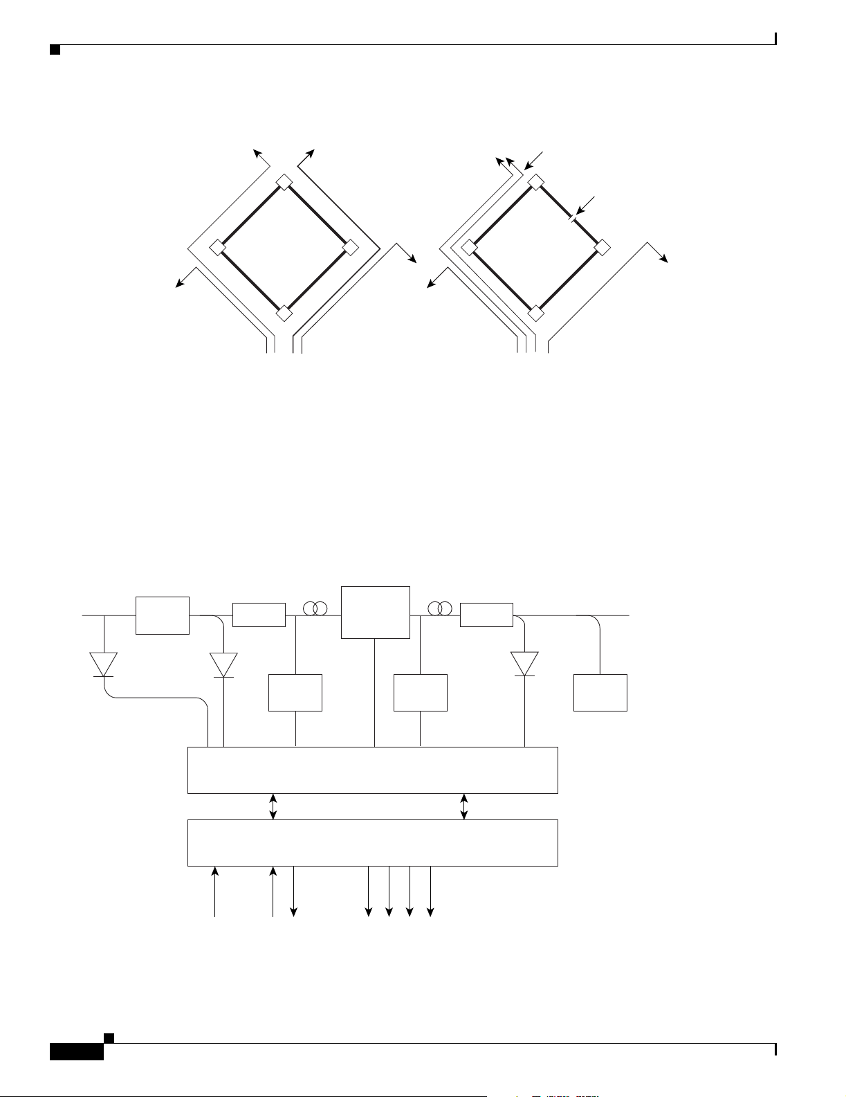
1.2 Wavelength Protection Switching
The ONS 15216 EDFA2 uses wavelength protection switching to restore wavelengths that are lost in the
event of a fiber cut or other loss of signal. Figure 1-1 on page 1-2 shows an example of wavelength
protection switching. In this example, two wavelengths are routed clockwise around a metro ring, and
two wavelengths are routed counter-clockwise around the same ring. Of the two counter-clockwise
wavelengths, only one transits the span linking locations D and C. If a fiber cut occurred on this span,
the affected wavelength could be restored by rerouting it (clockwise) around the ring to location D.
Wavelength protection switching minimizes the amount of bandwidth allocated for restoration because
only the affected wavelength is restored, not the entire fiber.
78-16033-01
Cisco ONS 15216 EDFA2 Operations Guide
1-1
Page 24
Key Features
Chapter 1 Applications
FINAL DRAFT - CISCO CONFIDENTIAL
Figure 1-1 Wavelength Protection Switching
Wavelength is rerouted
C
B
A
Before
After a protection switch occurs, the number of wavelengths on each fiber changes. In the example, the
number of clockwise wavelengths increases to three, while the number of counter-clockwise
wavelengths decreases to one.
1.3 Key Features
Figure 1-2 shows a block diagram of the ONS 15216 EDFA2.
Figure 1-2 ONS 15216 EDFA2 Block Diagram
C
D
B
A
After
Fiber Cut
D
61990
VOA
Gain
Isolator Isolator
Pump
Laser
Flattening
Filter
Pump
Laser
Control Circuit
Microcontroller
5VDC
External AlarmsRx Tx
RS232
Output Input
Output
Monitor
71172
1-2
Cisco ONS 15216 EDFA2 Operations Guide
78-16033-01
Page 25
Chapter 1 Applications
FINAL DRAFT - CISCO CONFIDENTIAL
The ONS 15216 EDFA2 has the following key features:
• Adjustable constant gain of 13 to 22 dB
• Gain flattening < 2 dB (peak to valley)
• Transient suppression
• Low noise figure of < 7 dB at –5 dBm input
• Simple Network Management Protocol (SNMP) MIBs
• Transaction Language 1 (TL1)
1.3.1 Constant Gain
Constant amplification (gain) per wavelength is important for ensuring that variations in power between
channels at the receivers is minimized. As wavelengths are added/dropped from an optical fiber, small
variations in gain between channels in a span can cause large variations in the power difference between
channels at the receivers. The ONS 15216 EDFA2 enables bandwidth-on-demand services by
guaranteeing that every wavelength is amplified by a value that can be set between 13 and 22 dB, no
matter how many wavelengths are being amplified.
Constant gain is achieved using an automatic control circuit that adjusts pump power when changes in
input power are detected. The ONS 15216 EDFA2 operates in Constant Gain Temperature Compensated
mode by default, but since there may be applications where other operating modes may be required, the
ONS 15216 EDFA2 can be set to operate in any one the following pump control modes:
Key Features
• Constant Gain Temperature Compensated mode
• Constant Output Power mode
• Constant Pump Current mode
• Constant Pump Power mode
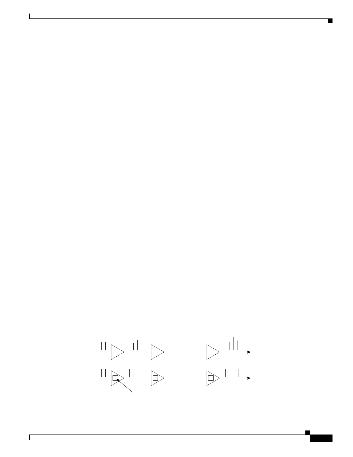
1.3.2 Gain Flattening
Figure 1-3 illustrates the effect of the gain flattening filter in the ONS 15216 EDFA2. Fiber (a) in the
figure shows a set of channels with equal powers being input to a cascaded network of amplifiers that
produce vastly different power levels and optical signal-to-noise ratios (OSNR) at the output. In contrast,
fiber (b) shows how the EDFAs effectively reduce this effect by introducing a gain flattening filter within
each amplifier.
Figure 1-3 Gain Flattening Filter
a
b
78-16033-01
Gain
Flattening
Filter
61984
Cisco ONS 15216 EDFA2 Operations Guide
1-3
Page 26

Key Features
FINAL DRAFT - CISCO CONFIDENTIAL
1.3.3 Transient Suppression
Transients in the performance of optical amplifiers are inevitable whenever the number of signals, or the
relative power of signals, changes. The ONS 15216 EDFA2 uses transient suppression to reduce the
amount of time required by an amplifier to recover from a change. This indicates the suitability of the
amplifier for add/drop applications like those described earlier.
1.3.4 Low Noise
Whenever there is gain in an optical system, noise also occurs. The predominant source of noise in
EDFAs is amplified spontaneous emission (ASE). The ONS 15216 EDFA2 has a low noise figure of less
than 7 dB at –5 dBm input.
1.3.5 SNMP MIBs
The ONS 15216 EDFA2 SNMP MIBs contain definitions of management information that allows
network systems to be remotely monitored, configured, and controlled.
Chapter 1 Applications
1.3.6 TL1
The ONS 15216 EDFA2 has a TL1 interface available to the network operator and craftsperson.
1-4
Cisco ONS 15216 EDFA2 Operations Guide
78-16033-01
Page 27

FINAL DRAFT - CISCO CONFIDENTIAL
Technical Specifications
This chapter discusses the technical specifications for the Cisco ONS 15216 EDFA2.
2.1 Optical Specifications
ONS 15216 EDFA2 optical specifications are listed and described in Tabl e 2-1.
Table 2-1 ONS 15216 EDFA2 Optical Specifications
Requirement Specification
Input signal wavelength 1530 nm to 1563 nm
Input power (channel total) –27 dBm to 4 dBm (total all channels)
CHAPTER
See the “Maximum Input Power” section on page 2-2 and
“Channel Loading” section on page 2-2 for more information.
2
Note In the event of a fiber cut or loss of connection, and
there is no input power, the ONS 15216 EDFA2 has
–3.5 dBm of output power. For additional safety
information, see the “Safety Requirements” section on
page 3-3.
Mode of operation Unidirectional (two common fibers: one transmit, one receive)
Maximum output power 17 ± 0.6 dBm
Signal gain per channel 13 dB to 22 dB
Channel gain deviation from setpoint ± 1.25 dB
Gain flattened < 2 dB (peak to valley)
Maximum noise figure < 7 dB at –5 dBm input power
Polarization mode dispersion (PMD) < 0.6 ps
Input/output optical return loss > 27 dB
Backward ASE power –30 dBm maximum
Polarization sensitivity < 0.5 dB
Automatic gain control (AGC) The ONS 15216 EDFA2 contains an active gain block with an
automatic gain control loop to minimize the effects of output
power variations per wavelength upon adding or deleting
wavelengths on the same DWDM ring.
78-16033-01
Cisco ONS 15216 EDFA2 Operations Guide
2-1
Page 28

Optical Specifications
FINAL DRAFT - CISCO CONFIDENTIAL
2.1.1 Maximum Input Power
The ONS 15216 EDFA2 operates at a gain setting between 13 and 22 dB. Each gain setting has a
maximum input power. The maximum input power is defined as 17 dBm (the maximum output power)
minus the gain setting. For example, at a gain setting of 22 dB, the maximum input power is –5 dBm. At
a gain setting of 13 dB, the maximum input power is 4 dBm. Prolonged operation beyond the maximum
input power can shorten the life of the ONS 15216 EDFA2.
External optical attenuators are required to reduce the total input power to less than or equal to 4 dBm.
2.1.2 Channel Loading
You can ensure a smooth upgrade path from a single channel to the maximum numbers of channels with
a minimum disruption of service if the per-channel power of the single channel is properly set from the
start. The per-channel power should be set so that at full channel loading, the total input power is less
than the maximum power indicated in Table 2- 2. For example, if the maximum number of channels at
full loading is 18 and the gain is set to 22 dB, the maximum per channel power is –17.6 dBm.
Use Tabl e 2-2 to calculate per-channel power as a function of the maximum total number of channels at
full loading. Contact Cisco TAC with any questions or concerns regarding maximum input power or
setting the upgrade path.
Chapter 2 Technical Specifications
Table 2-2 Maximum Channel Power
Composite Input
Power (dBm) 4 3 2 1 0 –1 –2 –3 –4 –5
Corresponding
Max. Gain (dB) 13 14 15 16 17 18 19 20 21 22
Number of
Channels at Full
Loading Maximum per Channel Input Power at Maximum Gain Setting (dBm)
1 4.0 3.0 2.0 1.0 0.0 –1.0 –2.0 –3.0 –4.0 –5.0
21.00.0–1.0 –2.0 –3.0 –4.0 –5.0 –6.0 –7.0 –8.0
3 –0.8 –1.8 –2.8 –3.8 –4.8 –5.8 –6.8 –7.8 –8.8 –9.8
4 –2.0 –3.0 –4.0 –5.0 –6.0 –7.0 –8.0 –9.0 –10.0 –11.0
5 –3.0 –4.0 –5.0 –6.0 –7.0 –8.0 –9.0 –10.0 –11.0 –12.0
6 –3.8 –4.8 –5.8 –6.8 –7.8 –8.8 –9.8 –10.8 –11.8 –12.8
7 –4.5 –5.5 –6.5 –7.5 –8.5 –9.5 –10.5 –11.5 –12.5 –13.5
8 –5.0 –6.0 –7.0 –8.0 –9.0 –10.0 –11.0 –12.0 –13.0 –14.0
9 –5.5 –6.5 –7.5 –8.5 –9.5 –10.5 –11.5 –12.5 –13.5 –14.5
10 –6.0 –7.0 –8.0 –9.0 –10.0 –11.0 –12.0 –13.0 –14.0 –15.0
11 –6.4 –7.4 –8.4 –9.4 –10.4 –11.4 –12.4 –13.4 –14.4 –15.4
12 –6.8 –7.8 –8.8 –9.8 –10.8 –11.8 –12.8 –13.8 –14.8 –15.8
13 –7.1 –8.1 –9.1 –10.1 –11.1 –12.1 –13.1 –14.1 –15.1 –16.1
14 –7.5 –8.5 –9.5 –10.5 –11.5 –12.5 –13.5 –14.5 –15.5 –16.5
15 –7.8 –8.8 –9.8 –10.8 –11.8 –12.8 –13.8 –14.8 –15.8 –16.8
2-2
Cisco ONS 15216 EDFA2 Operations Guide
78-16033-01
Page 29

Chapter 2 Technical Specifications
FINAL DRAFT - CISCO CONFIDENTIAL
Table 2-2 Maximum Channel Power (continued)
Composite Input
Power (dBm) 4 3 2 1 0 –1 –2 –3 –4 –5
Corresponding
Max. Gain (dB) 13 14 15 16 17 18 19 20 21 22
Number of
Channels at Full
Loading Maximum per Channel Input Power at Maximum Gain Setting (dBm)
16 –8.0 –9.0 –10.0 –11.0 –12.0 –13.0 –14.0 –15.0 –16.0 –17.0
17 –8.3 –9.3 –10.3 –11.3 –12.3 –13.3 –14.3 –15.3 –16.3 –17.3
18– –8.6 –9.6 –10.6 –11.6 –12.6 –13.6 –14.6 –15.6 –16.6 –17.6
19 –8.8 –9.8 –10.8 –11.8 –12.8 –13.8 –14.8 –15.8 –16.8 –17.8
20 –9.0 –10.0 –11.0 –12.0 –13.0 –14.0 –15.0 –16.0 –17.0 –18.0
21 –9.2 –10.2 –11.2 –12.2 –13.2 –14.2 –15.2 –16.2 –17.2 –18.2
22 –9.4 –10.4 –11.4 –12.4 –13.4 –14.4 –15.4 –16.4 –17.4 –18.4
23 –9.6 –10.6 –11.6 –12.6 –13.6 –14.6 –15.6 –16.6 –17.6 –18.6
24 –9.8 –10.8 –11.8 –12.8 –13.8 –14.8 –15.8 –16.8 –17.8 –18.8
25 –10.0 –11.0 –12.0 –13.0 –14.0 –15.0 –16.0 –17.0 –18.0 –19.0
26 –10.1 –11.1 –12.1 –13.1 –14.1 –15.1 –16.1 –17.1 –18.1 –19.1
27 –10.3 –11.3 –12.3 –13.3 –14.3 –15.3 –16.3 –17.3 –18.3 –19.3
28 –10.5 –11.5 –12.5 –13.5 –14.5 –15.5 –16.5 –17.5 –18.5 –19.5
29 –10.6 –11.6 –12.6 –13.6 –14.6 –15.6 –16.6 –17.6 –18.6 –19.6
30 –10.8 –11.8 –12.8 –13.8 –14.8 –15.8 –16.8 –17.8 –18.8 –19.8
31 –10.9 –11.9 –12.9 –13.9 –14.9 –15.9 –16.9 –17.9 –18.9 –19.9
32 –11.1 –12.1 –13.1 –14.1 –15.1 –16.1 –17.1 –18.1 –19.1 –20.1
Electrical Specifications
2.2 Electrical Specifications
The ONS 15216 EDFA2 uses a power supply that meets the electrical specifications listed in Tab le 2-3.
Table 2-3 ONS 15216 EDFA2 Electrical Specifications
Requirement Specification
Input voltage –48 VDC
Maximum power consumption < 25 W at 65
Minimum supply voltage –40 VDC
Minimum turn-on supply voltage –43 VDC
Maximum supply voltage –57 VDC or under
Maximum current 0.52 A
78-16033-01
°C end of life
Cisco ONS 15216 EDFA2 Operations Guide
2-3
Page 30

Mechanical Specifications
FINAL DRAFT - CISCO CONFIDENTIAL
2.3 Mechanical Specifications
Table 2-4 lists the ONS 15216 EDFA2 mechanical specifications.
Table 2-4 ONS 15216 EDFA2 Mechanical Specifications
Requirement Specification
Dimensions (H x W x D) 1 3/4 in. x 17 3/16 in. x 11 in. (4.4 cm x 43.7 cm x 27.9 cm)
Weight 5.45 lb (2.47 kg)
Ambient operating temperature 32
Storage temperature –40 to 185
Humidity operation Relative humidities of 5 to 95%, non-condensing. With ambient
Humidity storage Relative humidities of 5 to 95%, non-condensing. With ambient
Connector types SC/UPC Bulkhead connectors
Mean time between failures
(MTBF)
Chapter 2 Technical Specifications
to 122°F (0 to 50°C)
°F (–40 to 85°C)
temperatures above 84
limited to that corresponding to a specific humidity of 0.024
pounds of water per pound of dry air.
temperatures above 84
limited to that corresponding to a specific humidity of 0.024
pounds of water per pound of dry air.
12.7 years as per calculation procedure outlined in
TR-NWT-000332, Issue 4, Method 1
° F (29°C), the relative humidity may be
° F (29°C), the relative humidity may be
2.4 External Features
The ONS 15216 EDFA2 has the following external features:
• Front panel LEDs, graphics, and warning displays
• Brackets for rack mounting (including reversible ears that permit front, mid,
and rear mounting)
• Rear and side cooling vents
• Access door for fiber cleaning
• Fiber routing and retaining feature
• Two threaded grounding studs on rear and a pair of threaded grounding holes on each side
• Screw lug terminal block for power connection
• RJ-45 connector for external alarm connection
• RJ-45 connector for LAN connection
• SC/UPC connectors for optical interface
• DB-9 female connector for craft EIA/TIA-232 serial interface connection
Figure 2-1 on page 2-5 displays a mechanical outline of the external features and dimensions of the
ONS 15216 EDFA2.
2-4
Cisco ONS 15216 EDFA2 Operations Guide
78-16033-01
Page 31

Chapter 2 Technical Specifications
FINAL DRAFT - CISCO CONFIDENTIAL
Figure 2-1 ONS 15216 EDFA2 Dimensions
Front Panel
17 3/16 in. Width
1 3/4 in. Height
11 in. Dimension
2.5 Front Panel
Figure 2-2 shows the ONS 15216 EDFA2 front panel in detail. The front panel provides an all-front
access (fibers, power, alarm contact, and management interface) that complies with international
standards.
Figure 2-2 ONS 15216 EDFA2 Front Panel
-48V A
R A
-48V A
RET A
Fiber
input
port
Fiber
output
port
Fiber
output
monitor
port
Status
LEDs
POWER
FAIL
LOS
Power
level
warning
CISCO ONS 15216
(EIA/TIA-232)
RS-232
RS-232
Alarm
out
ALARM OUT
LAN port
LAN LEDs
71177
LAN
-48V B
R B
71176
-48V B
RET B
78-16033-01
Table 2-5 on page 2-6 describes the ONS 15216 EDFA2 front panel features.
Cisco ONS 15216 EDFA2 Operations Guide
2-5
Page 32

Front Panel
Chapter 2 Technical Specifications
FINAL DRAFT - CISCO CONFIDENTIAL
Table 2-5 ONS 15216 EDFA2 Front Panel Features
Feature Description
Terminal strip Terminal strip for supplying power to the ONS 15216 EDFA2. Attach
AWG 18 stranded power wires to appropriate terminals.
Threaded grounding holes Threaded grounding holes (#10-32) to ground the ONS 15216 EDFA2.
Alarm Out RJ-45 connector used for alarm system connection. (See the “Alarm
Out Relay Interface (RJ-45)” section on page 3-5 for additional
information.)
Serial port connection
(EIA/TIA-232)
Label Laser warnings, designation labels, and power level warning.
Status LEDs LEDs indicating status of power, fail, loss of signal, Ethernet link
Fiber input SC/UPC fiber input port.
Fiber output SC/UPC fiber output port.
Monitor output SC/UPC port for fiber that taps off 1% of output signal for monitoring
Chassis ground lugs Rear panel grounding post to attach chassis ground wire using #8-32
LAN RJ-45 connector used for 10BASE-T Ethernet connection. For more
Serial port for local or remote (modem) data communication
connection. (See Chapter 3, “Installation” for additional information.)
availability and Ethernet link traffic. (See the “Alarm LEDs” section
on page 3-6.)
purposes.
nut.
information, see the “LAN Interface (Ethernet)” section on page 3-14.
2-6
Cisco ONS 15216 EDFA2 Operations Guide
78-16033-01
Page 33

FINAL DRAFT - CISCO CONFIDENTIAL
Installation
3.1 Introduction
This chapter contains the installation procedures for the Cisco ONS 15216 EDFA2. The chapter is
divided into the following sections:
• Power (–48V A, RET A, –48V B, RET B, and chassis ground)
• Optical (fiber input and output ports)
• Communications (Alarm Out, LEDs, RS-232 (EIA/TIA-232), and LAN)
3.2 Standard Precautions
The following standard precautions should be taken when installing the ONS 15216 EDFA2:
CHAPTER
3
• Basic electrical precautions should be taken before powering up the ONS 15216 EDFA2.
• Using standard fiber handling and cleaning procedures is critical when installing optical networking
equipment.
• Eye safety precautions should be employed when handling fiber optic patchcords.
3.3 Placement and Power Connection
3.3.1 General Rack Considerations
The following potential hazards should be considered when installing the ONS 15216 EDFA2 within a
rack:
• Elevated Operating Ambient Temperature—If installed in a closed or multi-module rack assembly,
the operating ambient temperature of the rack environment may be greater than room ambient
temperature. Consideration should be given to installing the equipment in an environment
compatible with the manufacturer’s maximum rated ambient temperature.
• Reduced Air Flow—Installation of the equipment in a rack should be such that the amount of air
flow required for safe operation of the equipment is not compromised. Do not block ventilation
holes beyond what is allowed with supplied mounting brackets.
78-16033-01
Cisco ONS 15216 EDFA2 Operations Guide
3-1
Page 34

Placement and Power Connection
FINAL DRAFT - CISCO CONFIDENTIAL
• Mechanical Loading—Mounting of the equipment in the rack should be such that it avoids uneven
mechanical loading.
• Circuit Overloading—Consideration should be given to the connection of the equipment to the
supply circuit and the effect that overloading of circuits might have on overcurrent protection and
supply wiring. Appropriate consideration of equipment nameplate ratings should be used.
• Reliable Earthing—Reliable grounding of rack mounted equipment should be maintained. Particular
attention should be given to supply connections other than direct connections to the branch circuit
(i.e., use of power strip, etc.).
Chapter 3 Installation
Warning
The ONS 15216 EDFA2 is intended for installation in a restricted access area. A restricted access area
is where access can only be gained by service personnel through the use of a special tool, lock, key,
or other means of security. A restricted access area is controlled by the authority responsible for the
location.
3.3.2 Rack Installation and Power Supply Connection Procedures
Warning
Step 1 Mount the ONS 15216 EDFA2 in the rack (19 inches or 23 inches reversible ears). Empty rack space is
Step 2 Connect the –48 VDC power cable to the office fuse panel (user-provided).
Step 3 Connect power cable from the office fuse panel to the power bus A terminals on the ONS 15216 EDFA2.
Step 4 Repeat Step 3 for power bus B.
Before performing any of the following procedures, ensure that the power is removed from the DC
circuit. To ensure that all power is OFF, locate the circuit breaker on the panel board that services the
DC circuit, switch the circuit breaker to the OFF position, and tape the switch handle of the circuit
breaker in the OFF position.
Follow these steps to install the ONS 15216 EDFA2 into the rack and correctly set up the power supply:
not required above or below the ONS 15216 EDFA2.
a. 1.0A fusing is required (user-provided).
b. Use 18 AWG stranded wire (and wire lugs as appropriate).
See Figure 2-2 on page 2-5.
3-2
Step 5 Connect the facility ground to the ONS 15216 EDFA2 side panel ground using #10-32 x 3/8-inch
fasteners with lock washers and ground lugs, or connect to the rear panel ground using ring lugs for #8
studs.
Step 6 Insert 1.0A fuses into the fuse panel (user-provided).
The Power LED on the front panel of the ONS 15216 EDFA2 should illuminate when the power is
supplied.
Cisco ONS 15216 EDFA2 Operations Guide
78-16033-01
Page 35

Chapter 3 Installation
FINAL DRAFT - CISCO CONFIDENTIAL
3.4 SC/UPC Optical Ports
SC/UCP optical ports are as follows:
• Optical input signal to be amplified (INPUT)
–
Input must be between –27 dBm and +4 dBm
• Optically amplified output (OUTPUT)
• Optical monitored output signal (MONITOR OUT)
–
1% tap of output or 20 dB below output signal
3.4.1 Safety Requirements
SC/UPC Optical Ports
Warning
Warning
Warning
Procedures that require the fiber connections to be open must only be performed by service personnel
trained in laser safety requirements. Use of controls or performing adjustments or procedures other
than those specified herein may result in hazardous radiation exposure.
Class 1M laser radiation when open. Anyone working with the ONS 15216 EDFA2 must not allow their
eyes or body to be exposed to the laser beam or to a reflection from a mirror-like surface. Additionally,
viewing the laser output with certain optical instruments (eye loupes, microscopes) within a distance
of 100 mm may pose an eye hazard.
In the event of a fiber cut or loss of connection and there is no input power, the ONS 15216 EDFA2 still
has –3.5 dBm of optical output power.
The TL1, SNMP, and command-line interface (CLI) commands can be used to increase the level of laser
energy. Necessary precautions must be taken to avoid exposure to laser energy when using these
commands.
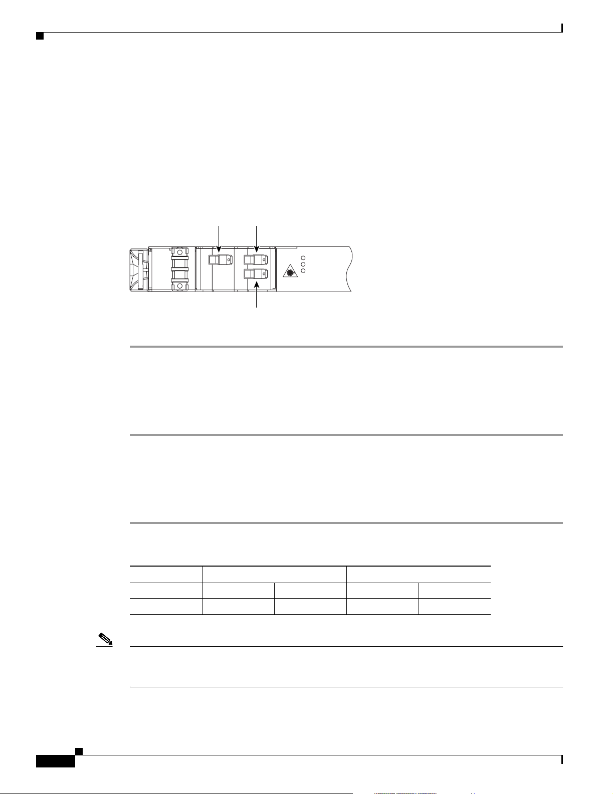
3.4.2 Optical Connection Procedure
Warning
Follow all directions and warning labels when working with optical fibers. To prevent eye damage,
never look directly into a fiber or connector.
78-16033-01
Connect the customer-supplied fiber optic patchcords to the SC/UPC optical ports of the
ONS 15216 EDFA2 using the following procedure. Refer to Figure 3-1 on page 3-4 while performing
this procedure:
Step 1 Clean both ends of the two fiber optic patchcords. Refer to the Cisco document “Cleaning Procedure for
Fiber Optic Connectors” for more information.
Step 2 Connect the first patchcord between the ONS 15216 EDFA2 OUTPUT connector and the FACILITY
LINE connection.
The measured optical output power should be approximately –3.5 dBm.
Cisco ONS 15216 EDFA2 Operations Guide
3-3
Page 36
SC/UPC Optical Ports
Step 3 Connect the second patchcord to TERMINAL OUTPUT. Measure and record the total optical power:
Step 4 If optical power at the end of the TERMINAL OUTPUT patchcord is less than or equal to +4 dBm,
Chapter 3 Installation
FINAL DRAFT - CISCO CONFIDENTIAL
a. DWDM/OADM output
b. Terminal transmitter output
connect the end to the ONS 15216 EDFA2 input. If the optical power is greater than + 4 dBm, additional
optical attenuation is required to bring optical power below + 4 dBm.
Figure 3-1 ONS 15216 EDFA2 Optical Connections
Fiber
input
-48V A
R A
Fiber
output
POWER
FAIL
LOS
71175
Fiber output
monitor
3.4.3 Optical Amplification Operation Verification Procedure
To verify ONS 15216 EDFA2 optical amplification, use the following procedure:
Step 1 Connect an optical power meter to the MONITOR OUT port.
Step 2 Measure and record the output power. The MONITOR OUT port level is –20 dB less than the signal.
Step 3 Verify that the ONS 15216 EDFA2 input and output power are within the range shown in Table 3-1.
For example, if the total input power is between –27 dBm and –5 dBm, expect an output power between
–5 dBm and 17 dBm.
3-4
Table 3-1 Gain Range
Gain Total Input Power (dBm) Total Output Power (dBm)
(dB) Min Max Min Max
22 –27 –5 –517
Note Unless overridden by the user, the gain per channel is by default set to 22 dB by the ONS 15216 EDFA2.
Gain is fixed at 22 dB as long as total input power is less than or equal to –5 dBm. If your input power
is higher than –5 dBm, see the “Set Gain” section on page 4-5.
Cisco ONS 15216 EDFA2 Operations Guide
78-16033-01
Page 37

Chapter 3 Installation
FINAL DRAFT - CISCO CONFIDENTIAL
3.5 Communications
The ONS 15216 EDFA2 can communicate in the following ways:
• Alarm Out relay contacts (RJ-45)
• Alarm LEDs
• Serial interface (EIA/TIA-232)
• Serial interface connected to a modem
• LAN interface (RJ-45)
3.5.1 Alarm Out Relay Interface (RJ-45)
The ONS 15216 EDFA2 Alarm Out (RJ-45) port reports alarm status for the following:
• Loss or degradation of electrical power
• Laser pump overheating or excessive pump current, output power, gain, and case temperature
• Loss or degradation of optical network
Communications
These alarms can be connected to a network operations center (NOC) network management system
(NMS) using the following methods:
• Cisco ONS 15454 miscellaneous discrete input
• Central Office alarm panel/system
Table 3-2 provides the ONS 15216 EDFA2 RJ-45 alarm out pinout and alarm definitions.
Table 3-2 Alarm Pinout and Definitions (RJ-45)
Relay Pinout Description
0 1 (0+) Loss of electrical power
2 (0–)
1 3 (1+) Laser pump temperature or bias is out of range; input power is out of
4 (1–)
2 5 (2+) Loss of optical input signal or input signal is below threshold (Minor)
6 (2–)
3 7 (3+) Loss of electrical power or out of range for Bus A or Bus B while in duplex
8 (3–)
tolerance for gain settings (Major)
mode
3.5.1.1 Alarm Relay Connection Procedure
78-16033-01
To set up alarm contacts, follow these steps:
Step 1 Connect the RJ-45 to the stub-end cable using a #22 AWG solid wire.
Note Cable and connector are not provided.
Cisco ONS 15216 EDFA2 Operations Guide
3-5
Page 38

Communications
Step 2 Connect the alarm cable to the alarm system contacts:
a. Cisco ONS 15454 medium-dependent interface (MDI) wire wrap pins
b. Central office (CO) alarm panel
Refer to Table 3-2 on page 3-5 for information concerning alarm contacts. Refer to Alarm LEDs, page
3-6 for information on the ONS 15216 EDFA2 alarm LEDs.
3.5.2 Alarm LEDs
The ONS 15216 EDFA2 has five LEDs:
• POWER
• FAI L
• LOS
• Ethernet socket (2)
Three of these LEDs, POWER, FAIL, and LOS, are located at the left side of the front panel of the
ONS 15216 EDFA2. The two Ethernet LEDs are located at the top left and right sides of the Ethernet
socket. When the module is powered on, an LED test is performed.
Chapter 3 Installation
FINAL DRAFT - CISCO CONFIDENTIAL
3.5.2.1 POWER LED (Green)
The POWER LED is green. This LED functions as follows:
• On: –48 VDC power is within tolerance. (Power Bus A and B are powered normally.)
• Off: No –48 VDC power or power is out of tolerance from the internal power supply. (Power Bus A
and B are not powered.)
• Flashing: Power Bus A or B (in duplex mode) has failed or is out of tolerance, or Power Bus A (in
simplex mode) is out of tolerance.
In the off condition, the first pair of alarm relay contacts in the RJ-45 connector changes from a normally
open condition to a closed condition. The LED and alarm automatically reset when the condition clears.
(For additional alarm contact closure information, see the “Alarm Out Relay Interface (RJ-45)” section
on page 3-5.)
3.5.2.2 FAIL LED (Red)
The FAIL LED is red. This LED functions as follows:
• On: The laser pump bias, laser pump temperature, output power, gain, or case temperature is out of
tolerance. (A major internal failure has occurred.)
• Off: The laser pump bias or laser pump temperature is in the specified range (or no –48 VDC power
is present).
In the on condition, the second pair of alarm relay contacts in the RJ-45 connector changes from a
normally open to a closed condition. If an invalid input optical signal is applied to the
ONS 15216 EDFA2, the Fail LED is illuminated. The LED and alarm automatically reset when the
condition clears.
3-6
Cisco ONS 15216 EDFA2 Operations Guide
78-16033-01
Page 39

Chapter 3 Installation
FINAL DRAFT - CISCO CONFIDENTIAL
3.5.2.3 LOS LED (Yellow)
The loss of signal (LOS) LED is yellow. This LED functions as follows:
• On: The optical input power to the ONS 15216 EDFA2 is below the loss of input threshold. (A LOS
threshold decision occurs.)
• Off: The optical input power is within the input threshold (or no –48 VDC power is present).
In the on condition, the third pair of alarm relay contacts in the RJ-45 connector changes from a normally
open condition to a closed condition. The LED and alarm automatically reset when the condition clears.
3.5.2.4 Ethernet Socket LEDs
Two LEDs are located at the top left and right sides of the Ethernet socket. These LEDs are both green.
These LEDs function as follows:
• If left Ethernet socket LED is on, the link is up.
• If right Ethernet socket LED is on or flashing, there is Ethernet traffic.
Communications
3.5.3 Serial Interface (EIA/TIA-232) Communication
This section describes communication with the ONS 15216 EDFA2 using a serial connection.
3.5.3.1 Required Equipment
Establishing a serial communications link with a ONS 15216 EDFA2 requires the equipment listed in
Table 3-3.
Table 3-3 Equipment Checklist
Hardware Comments
Laptop or computer running a Terminal
application.
EIA/TIA-232 cable with DB-9F/DB-9M
connectors wired as shown in Figure 3-8 on
page 3-14.
3.5.3.2 Serial Connection Procedure
To set up an EIA/TIA-232 link to the ONS 15216 EDFA2, use the following procedure. (The procedure
uses HyperTerminal and a connection via the COM1 port.)
User-provided. HyperTerminal can be found in the
Microsoft Windows Accessories menu.
Provides EIA/TIA-232 link to ONS 15216 EDFA2.
78-16033-01
Step 1 Connect the DB-9F end of the EIA/TIA-232 data cable (straight cable, user provided) to the laptop COM
port.
Step 2 Connect the DB-9M end of the EIA/TIA-232 data cable to the RS-232 (EIA/TIA-232) serial port
connection on the front panel of the ONS 15216 EDFA2.
Step 3 Open HyperTerminal. (HyperTerminal can be found in the Microsoft Windows Accessories menu.)
Step 4 Type Optical Amplifier, select an icon, and click OK.
Cisco ONS 15216 EDFA2 Operations Guide
3-7
Page 40
Communications
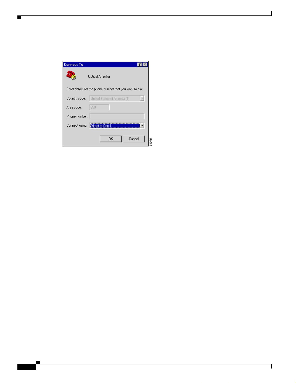
Step 5 In the Connect To dialog box (Figure 3-2), click Direct to Com1 in the Connect using field. Click OK.
Chapter 3 Installation
FINAL DRAFT - CISCO CONFIDENTIAL
Figure 3-2 HyperTerminal Connect To Dialog Box
Step 6
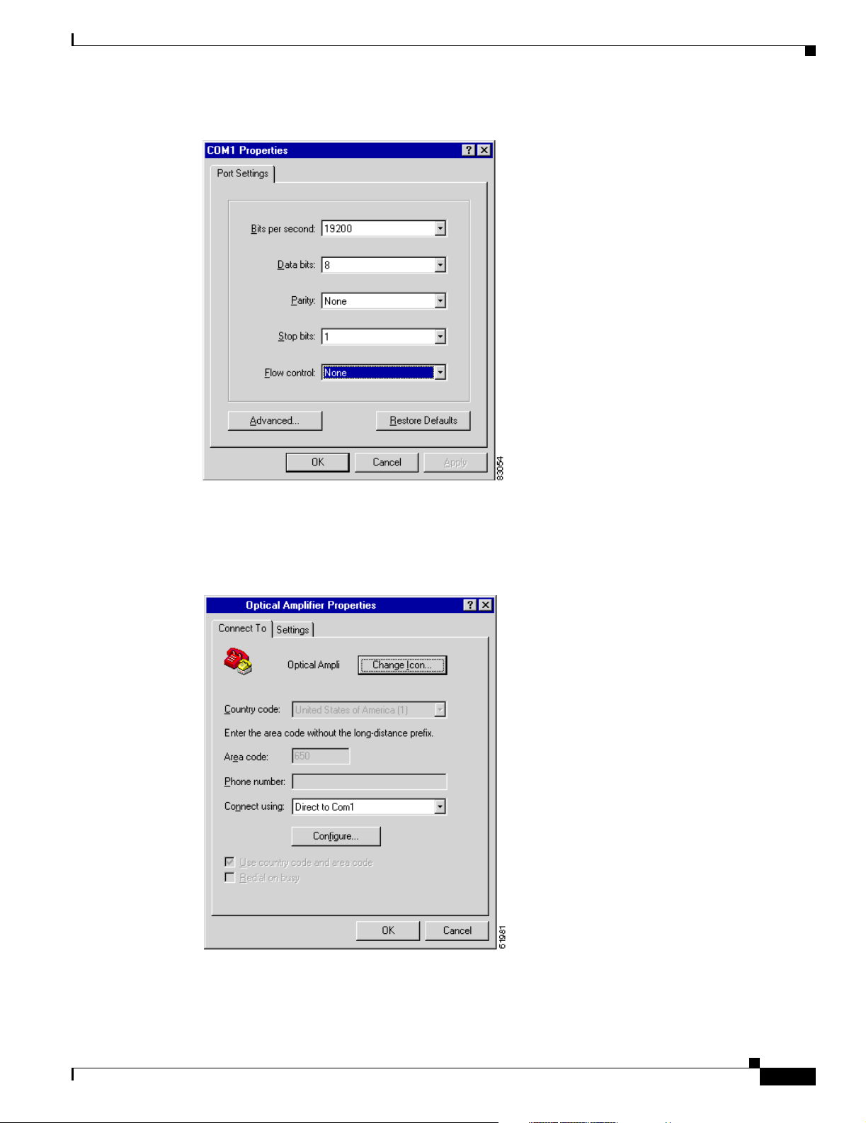
Configure the Port Settings in the COM1 Properties dialog box as shown in Figure 3-3 on page 3-9. The
Port Settings must be configured as follows:
• Bits per second—19200
• Data bits—8
• Parity—None
• Stop bits—1
• Flow control—None
Click OK when done.
3-8
Cisco ONS 15216 EDFA2 Operations Guide
78-16033-01
Page 41
Chapter 3 Installation
Communications
FINAL DRAFT - CISCO CONFIDENTIAL
Figure 3-3 HyperTerminal COM1 Properties Dialog Box
Step 7
Step 8 Click Connect To tab in the Optical Amplifier Properties dialog box as shown in Figure 3-4.
In the HyperTerminal main window, click File > Properties.
Figure 3-4 Optical Amplifier Properties Dialog Box (Connect To Tab)
78-16033-01
Step 9
Step 10 Click Settings (Figure 3-5 on page 3-10) and click ASCII Setup.
Ensure that Direct to Com1 is selected in the Connect using field.
Cisco ONS 15216 EDFA2 Operations Guide
3-9
Page 42

Communications
Chapter 3 Installation
FINAL DRAFT - CISCO CONFIDENTIAL
Figure 3-5 Optical Amplifier Properties Dialog Box (Settings Tab)
Step 11
Step 12
Configure the ASCII Setup window as shown in Figure 3-6. Click OK when done.
Figure 3-6 HyperTerminal ASCII Setup Dialog Box
Click OK to return to the main HyperTerminal window.
The ONS 15216 EDFA2 login screen appears. The appearance depends on the shell the
ONS 15216 EDFA2 is set to (TL1 is the default shell). See “Log In via RS-232 (EIA/TIA-232) Port
Using HyperTerminal” section on page 4-1 for the login procedure in ASH shell and “Log In via RS-232
(EIA/TIA-232) Port Using HyperTerminal” section on page 8-1 for the login procedure in TL1 shell.
3-10
Cisco ONS 15216 EDFA2 Operations Guide
78-16033-01
Page 43

Chapter 3 Installation
FINAL DRAFT - CISCO CONFIDENTIAL
3.5.4 Serial Interface Remote Communication via Modem
This section describes the procedure for establishing a remote dial-up connection to the
ONS 15216 EDFA2. ONS 15216 EDFA2 remote communication requires two US Robotics 56K Fax
modems set up to send data over a two-wire dial-up telephone line. (See Figure 3-7.)
This section assumes the use of the US Robotics 56K Fax modem V.90. Other modem types may require
different settings to establish a remote dial-up connection. The user should review their modem
documentation to ensure compatibility between US Robotics and other vendor modem types.
Figure 3-7 Remote Communication
Network
Modem
Workstation
PSTN Dial up
Phone line
3.5.4.1 Remote Communication Component Requirements
Modem
Cisco ONS 15216
EDFA2
Communications
71458
Table 3-4 lists the components required to communicate remotely with a ONS 15216 EDFA2. Table 3- 4
is divided into two sections: Remote Site and Local Site. The Remote Site section lists components
needed at the site that contains the ONS 15216 EDFA2 and the Local Site section lists components
needed at the site where the user is located.
Table 3-4 Communication Component List
Component Notes
Remote Site
1 ONS 15216 EDFA2
1 US Robotics 56K Fax modem V.90 The modem to ONS 15216 EDFA2
connection must be set for 19200 baud.
The modem to modem connection must
be set for 14400 baud.
1 10-ft DB-25M to DB-9F cable For connection between
ONS 15216 EDFA2 and modem.
1 RJ-11 to RJ-11 telephone cable For connection between the modem and
PSTN dial-up telephone line
1 public switched telephone network
(PSTN) dial-up telephone line
Local Site
1 PC running HyperTerminal
US Robotics 56K Fax modem V.90 The modem to ONS 15216 EDFA2
connection must be set for 19200 baud.
The modem to modem connection must
be set for 14400 baud.
1 10-ft DB-25M to DB-9F For connection between PC COM port
and modem.
78-16033-01
Cisco ONS 15216 EDFA2 Operations Guide
3-11
Page 44

Communications
FINAL DRAFT - CISCO CONFIDENTIAL
Table 3-4 Communication Component List
Component Notes
1 RJ-11 to RJ-11 telephone cable For connection between the modem and
1 PSTN dial-up telephone line
3.5.4.2 Modem Signals
The only signals required for communication are TXD (transmit), RXD (receive), and SIGNAL
GROUND. By adjusting the modem manufacturer settings, the other signals can be ignored.
3.5.4.3 Modem Power Up
The modem has a DIP switch that overrides certain NVRAM settings during a power up. For consistent
operation throughout the power cycles, the DIP switches must be set as displayed in Table 3-5.
Table 3-5 Modem DIP Switch Setting
Chapter 3 Installation
PSTN dial-up telephone line.
DIP Switch Setting Up (U) or Down (D) Description
1 D Data terminal ready override
2U Verbal result codes
3 U Suppress result codes
4 D No echo, offline commands
5 U Auto-answer on first ring, or higher if
6 U Carrier detect normal
7 U Load NVRAM defaults
8 D Smart mode
3.5.4.4 Modem Configuration Settings
After configuring the DIP switch settings, each modem configuration must then be set using a terminal
program such as Microsoft Windows HyperTerminal.
Connect the modem to the PC serial port using a DB-25M to DB-9F modem cable as per the
manufacturer recommendations.
Set the terminal communication parameters as follows:
• 19,200 baud
• No parity
specified in NVRAM
3-12
• 8 bits per character
• 1 stop bit, and no flow control
Table 3-6 on page 3-13 gives a brief description of the modem settings that are stored in NVRAM. These
settings survive power supply interruptions. Use these settings to configure each modem.
Cisco ONS 15216 EDFA2 Operations Guide
78-16033-01
Page 45

Chapter 3 Installation
Communications
FINAL DRAFT - CISCO CONFIDENTIAL
Table 3-6 Modem Settings
Modem Setting Description
b0 ITU-T answer sequence
e0 Echo off
f1 Local echo off
m1 Speaker on until CONNECT
q1 Quiet mode; no results code
v1 Verbal codes
x1 Select result codes displayed
y0 Use profile 0 setting in NVRAM
&a3 Enable extra result codes
&b1 Fixed DTE speed
&c1 Normal CD operation
&d0 DTR override
&g0 No guard tone, U.S. and Canada
&h0 Flow control disabled
&i0 Software flow control disabled
&k0 Data compression disabled
&m5 ARQ mode
&n8 Fix highest connect speed to 14,400 bps
&p1 Pulse dialing option
&r1 Ignore Request to Send (RTS)
&s1 Modem controls Data Set Ready (DSR)
&t5 Prohibits remote digital loopback
&u8 Fix lowest connect speed to 14,400 bps
&y1 Break handling; destructive/expedited
&w0 Store configuration 0
s0=1 Auto-answer on first ring
s2=128 Disable escape to command mode
3.5.4.5 Setting and Saving Modem Settings
To set and save modem settings, enter the following command to the terminal program and to each
modem:
atb0e0f1m1q1v1x1y0
at&a3&b1&c1&d0&g0&h0&i0&k0s0=1
at&m5&n8&7p1&r1&s1&t5&u8&y1s2=128
at&w0
78-16033-01
Cisco ONS 15216 EDFA2 Operations Guide
3-13
Page 46

Communications
FINAL DRAFT - CISCO CONFIDENTIAL
Note Modem communication is not necessary unless dial-up remote communication is desired.
3.5.4.6 PC Connection via Modem
The ONS 15216 EDFA2 and modem are connected through the RS-232 (EIA/TIA-232) port using a
DB-9 connector. The modem, PC, and ONS 15216 EDFA2 should be physically set up as displayed in
Figure 3-8. Use Figure 3-8 to properly connect the ONS 15216 EDFA2 to the modem.
Figure 3-8 DB-9 Pinout for RS-232 (EIA/TIA-232) Port
GND RXD TXD
Chapter 3 Installation
5
432
98
76
CTSRTS
Using the terminal program from the PC, enter the ATD T command with the appropriate telephone
number to call the remote ONS 15216 EDFA2 modem. After the modems synchronize, log into the
ONS 15216 EDFA2 using the correct user name and password. Refer to Chapter 5, “SNMP MIB
Installation and Configuration,” Chapter 6, “ASH Commands,” and Chapter 9, “TL1 Commands,” for
additional information on commands.
3.5.5 LAN Interface (Ethernet)
You can connect to the ONS 15216 EDFA2 to an Ethernet LAN for remote access.
Note Before communicating and managing the ONS 15216 EDFA2 via the Ethernet port, the user must first
enter an IP address. To set an IP address, see Chapter 4, “Provisioning Using ASH and SNMP” or
Chapter 8, “Provisioning Using TL1.”
Telnet is an application that allows remote management using IP over the Ethernet LAN. The following
types of commands can be issued through a Telnet session:
• SNMP MIB commands (Chapter 5, “SNMP MIB Installation and Configuration”)
1
71173
3-14
• ASH CLI commands (Chapter 6, “ASH Commands”)
• TL1 commands (Chapter 9, “TL1 Commands”)
Cisco ONS 15216 EDFA2 Operations Guide
78-16033-01
Page 47

Chapter 3 Installation
FINAL DRAFT - CISCO CONFIDENTIAL
3.5.5.1 LAN Connection Procedure
Use the following procedure to configure the module to accept SNMP, CLI, and TL1 commands via its
RJ-45 LAN port:
Step 1 The ONS 15216 EDFA2 IP address is factory set at 0.0.0.0. The IP address must be set before the
ONS 15216 EDFA2 can be accessed via the Ethernet port. See “Set IP Address” section on page 4-3.
Step 2 Connect ONS 15216 EDFA2 to the network via the module LAN port.
Use a straight-through Cat5 Ethernet cable with RJ-45 connectors to connect to a LAN, or use a
cross-over cable if connecting directly to a PC.
Step 3 At a terminal or workstation, open the Telnet application.
Note To send CLI and TL1 commands over IP, a Telnet client is required. For SNMP management over
IP, a generic SNMP manager is required.
Step 4 Connect to the ONS 15216 EDFA2 using the module’s IP address.
If you do not specify a port number, the ONS 15216 EDFA2 responds in the shell that the
ONS 15216 EDFA2 is set to (TL1 is the default shell). Specify port number 8023 to access through the
ASH shell or port number 3083 to access through the TL1 shell.
The ONS 15216 EDFA2 login screen appears. See “Log In via RS-232 (EIA/TIA-232) Port Using
HyperTerminal” section on page 4-1 for the login procedure in ASH shell and “Log In via RS-232
(EIA/TIA-232) Port Using HyperTerminal” section on page 8-1 for the login procedure in TL1 shell.
Communications
78-16033-01
Cisco ONS 15216 EDFA2 Operations Guide
3-15
Page 48

Communications
Chapter 3 Installation
FINAL DRAFT - CISCO CONFIDENTIAL
3-16
Cisco ONS 15216 EDFA2 Operations Guide
78-16033-01
Page 49

FINAL DRAFT - CISCO CONFIDENTIAL
CHAPTER
4
Provisioning Using ASH and SNMP
This chapter discusses the provisioning procedures for the Cisco ONS 15216 EDFA2 using SNMP and
a proprietary command line interface named the ASH shell. See Chapter 8, “Provisioning Using TL1”
for provisioning information using TL1 commands in the TL1 shell.
The provisioning procedure for the ONS 15216 EDFA2 in the ASH shell is as follows:
1. Log In via RS-232 (EIA/TIA-232) Port Using HyperTerminal, page 4-1
2. Set IP Address, page 4-3
3. Log In via LAN Port Using Telnet (Optional), page 4-3
4. Set Date and Time, page 4-4
5. Set Power Bus Mode (Simplex or Duplex), page 4-4
6. Verify Amplifier Operational Status, page 4-4
7. Set Gain, page 4-5
8. Set Alarm Thresholds, page 4-5
9. Set Password, page 4-10
10. Add Users, page 4-11
11. Save Changes, page 4-11
12. Log Off, page 4-12
13. Back Up System Configuration, page 4-12
14. Restore System Configuration, page 4-13
15. Recover Default Password, page 4-14
The following sections describe these steps in detail.
4.1 Log In via RS-232 (EIA/TIA-232) Port Using HyperTerminal
Logging in through the RS-232 (EIA/TIA-232) port is required to set the ONS 15216 EDFA2 IP address
before there can be access via the LAN port. (See “Log In via LAN Port Using Telnet (Optional)” section
on page 4-3.)
Step 1 Connect to the RS-232 (EIA/TIA-232) port on the front panel. See “Serial Connection Procedure”
section on page 3-7 for line connection and HyperTerminal setup instructions.
Step 2 Open HyperTerminal. (HyperTerminal can be found in the Microsoft Windows Accessories menu.)
78-16033-01
Cisco ONS 15216 EDFA2 Operations Guide
4-1
Page 50

Log In via RS-232 (EIA/TIA-232) Port Using HyperTerminal
FINAL DRAFT - CISCO CONFIDENTIAL
Step 3 If you see the login window shown in Example 4-1 on page 4-2, skip to Step 4.
By default the ONS 15216 EDFA2 is in TL1 shell, so this step may be required to proceed in ASH shell.
When in TL1 shell, the screen opens to a simple prompt (
ASH shell, log in using the procedure in “Log In via RS-232 (EIA/TIA-232) Port Using HyperTerminal”
section on page 8-1, and then enter the following command at the sid/tid name prompt:
Welcome to ONS15216 EDFA2 Console (v2.3.0)
sidtidname:ONS15216 EDFA2> ED-NE-GEN:::123:::CLI=ASH;
Then enter the following command at the hostname prompt:
sidtidname:ONS15216 EDFA2> INIT-SYS::ALL:1234::1;
The ONS 15216 EDFA2 should log you off and then bring up the ASH shell login window.
Step 4 Check that the ONS 15216 EDFA2 login window appears as shown in Example 4-1.
Example 4-1 ASH Shell Login Window
-- LOGIN ---------------------------------------------------- sysname
ONS15216 EDFA2 Optical Amplifier
Chapter 4 Provisioning Using ASH and SNMP
sidtidname:ONS15216 EDFA2>). To change to
--------------------------------
Software Version 2.3.0
Copyright (c) 2000-2003 Cisco Systems, Inc.
Username: { }
Password: { }
[Login]
Step 5 Enter both a user name and password.
The default user name and password is CISCO15 with no password (press Enter).
Note For security reasons, it is recommended to change the password from its default value. See Set Password,
page 4-10 or Set Password, page 8-10.
Step 6 Press Enter when [Login] becomes highlighted. Example 4-2 displays the login response.
Example 4-2 ASH Shell Login Response
Welcome to ONS15216 EDFA2 Console (v2.3.0)
4-2
ash:hostname:ONS15216 EDFA2>
An EIA/TIA-232 link to the ONS 15216 EDFA2 is established. The user can now provision the
ONS 15216 EDFA2.
Cisco ONS 15216 EDFA2 Operations Guide
78-16033-01
Page 51

Chapter 4 Provisioning Using ASH and SNMP
FINAL DRAFT - CISCO CONFIDENTIAL
4.2 Set IP Address
Before connecting the ONS 15216 EDFA2 to a LAN, it is mandatory to set the ONS 15216 EDFA2 IP
address through a local serial communication interface using the RS-232 (EIA/TIA-232) port on the
front of the module.
Step 1 If you do not know the ONS 15216 EDFA2’s IP address, subnet mask, gateway address, or host name,
contact your network administrator.
Step 2 At the command prompt, enter the snmp row set local cerent15216EdfaSromIpMgmtGroup
command (displayed in Example 4-3) and press Enter.
Example 4-3 Setting IP Address, Subnet Mask, Gateway Address, and Host Name
ash:hostname:ONS15216 EDFA2> snmp row set local cerent15216EdfaSromIpMgmtGroup
cerent15216EdfaSromIpMgmtEnetAddress 0.0.0.0
cerent15216EdfaSromIpMgmtEnetSubNetMask 0.0.0.0
cerent15216EdfaSromIpMgmtDefaultRouterAddress 0.0.0.0
cerent15216EdfaSromIpMgmtHostName ""
Set IP Address
Because row set is being used in this command, the user is prompted row by row to enter the IP address,
the subnet mask, the gateway address, and the host name (community ID).
Step 3 The changes must be saved prior to terminating the session. See “Save Changes” section on page 4-11.
Step 4 The system must be rebooted to make the IP address active. Use the processor reset command. (See
“processor reset Command” section on page 6-12.)
4.3 Log In via LAN Port Using Telnet (Optional)
Provisioning of the ONS 15216 EDFA2 can be accomplished entirely through the RS-232
(EIA/TIA-232) port using CLI commands. After an IP address is assigned, it may be easier to provision
the ONS 15216 EDFA2 using Telnet or an SNMP manager. A Telnet client is needed for CLI commands
over IP. A generic SNMP manager is required for SNMP management over IP. After connecting the
ONS 15216 EDFA2 to the network through its RJ-45 LAN port (see “LAN Interface (Ethernet)” section
on page 3-14), the user can configure the module to accept SNMP and CLI commands via Telnet using
the following procedure:
Step 1 Connect to the LAN port on the front panel. See “LAN Connection Procedure” section on page 3-15.
Step 2 Click the Microsoft Windows Start menu and select Run.
Step 3 In the text field, type the following:
telnet <ONS 15216 EDFA2 IP address> 8023
78-16033-01
Specifying port 8023 ensures login through the ASH shell. If no port is specified, the
ONS 15216 EDFA2 responds in the shell that the ONS 15216 EDFA2 is set to. (TL1 is the default shell.)
Cisco ONS 15216 EDFA2 Operations Guide
4-3
Page 52

Set Date and Time
FINAL DRAFT - CISCO CONFIDENTIAL
Step 4 Log in again using Step 4 through Step 6 in “Log In via RS-232 (EIA/TIA-232) Port Using
HyperTerminal” section on page 4-1.
You are now connected to the ONS 15216 EDFA2 via Telnet.
4.4 Set Date and Time
Use the snmp attribute set local cerent15216EdfaRtcDateAndTimeLocalString command to set the
date, time, and time zone. Entries must follow this format: “yyyy-m-d,h:m:s.s +h:m”. Following the
space, the time zone is set as +/– hours from Greenwich Mean Time (GMT) (also designated as universal
coordinated time (UTC)) followed by a colon and minutes ahead for daylight savings. For example,
Pacific Daylight Time would be –8:60 and Greenwich Mean Time would be +0:0. See Example 4-4.
Example 4-4 Setting the Date and Time
ash:hostname:ONS15216 EDFA2> snmp attribute set local cerent15216EdfaRtcDateAndTimeLocalString
"2002-6-30,14:8:30.0 -8:60"
Chapter 4 Provisioning Using ASH and SNMP
4.5 Set Power Bus Mode (Simplex or Duplex)
The ONS 15216 EDFA2 allows users to set a simplex (one power source–Bus A) or duplex (redundant
power source–Bus A and Bus B) Power Bus mode. Use the snmp attribute set local
cerent15216EdfaPowerBusMode command to set the desired Power Bus mode. The default mode is
duplex. See Example 4-5.
Example 4-5 Setting the Power Bus Mode
ash:hostname:ONS15216 EDFA2> snmp attribute set local cerent15216EdfaPowerBusMode simplex
4.6 Verify Amplifier Operational Status
To ensure that the amplifier is working correctly on the optical level, you must verify the amplifier
operational status. Use the snmp table display local cerent15216EdfaOverallStatusGroup command
to verify amplifier operational status. Example 4-6 displays the output of this command.
Example 4-6 Verifying the Amplifier Operations Status
ash:hostname:ONS15216 EDFA2> snmp table display local cerent15216EdfaOverallStatusGroup
CLASS CERENT-15216-EDFA-MIB.cerent15216EdfaOverallStatusGroup ::=
{
cerent15216EdfaInPoweruW = 279;
cerent15216EdfaInPowerdBm = -1555;
cerent15216EdfaOutPowermW = 476;
cerent15216EdfaOutPowerdBm = 678;
cerent15216EdfaConstGainOverallGainMeasured = 219;
cerent15216EdfaVariableGainPreAttenuationMeasured = 10;
};
4-4
Cisco ONS 15216 EDFA2 Operations Guide
78-16033-01
Page 53

Chapter 4 Provisioning Using ASH and SNMP
FINAL DRAFT - CISCO CONFIDENTIAL
The input power (signal) should be consistent with the input power measured during the optical
connection procedure. See the “Optical Connection Procedure” section on page 3-3 for more
information. The output power value should be 22 dB greater than the input, assuming that the default
gain setting is 22 dB.
Note An input power higher than –5 dBm will return a Gain Out of Range alarm that can be cleared by
correctly setting the gain value. For more information, refer to Table 2-2 on page 2-2.
4.7 Set Gain
To ensure that the ONS 15216 EDFA2 output signal is received by the transceiver in the network
element, it is important that the gain is set correctly.
The desired output power per channel is dependent on the number of channels traversed in the amplifier.
The user sets the gain of the amplifier depending on the input power (signal) level, the network
application, and the required receiver specifications necessary for error-free operation. Gain range is
provided in Table 3-1 on page 3-4.
Set Gain
To set the amplifier gain, enter the snmp attribute set local cerent15216EdfaConstGainOverallGain
gainvalue command, where gainvalue is the desired gain multiplied by ten. For example, if the desired
gain is 20 dB, the gainvalue would be set to 200. Example 4-7 shows the command used to set the gain.
Example 4-7 Setting the Gain
ash:hostname:ONS15216 EDFA2> snmp attribute set local cerent15216EdfaConstGainOverallGain 200
Note Prior to changing or implementing gain changes, consult with the Cisco TAC to ensure proper network
operation.
4.8 Set Alarm Thresholds
Alarm thresholds are set so that the network operator can be notified when valid alarms occur via the
RJ-45 ALARM OUT and RJ-45 LAN ports on the front panel of the ONS 15216 EDFA2. (See Figure 4-1
on page 4-6.)
78-16033-01
Cisco ONS 15216 EDFA2 Operations Guide
4-5
Page 54
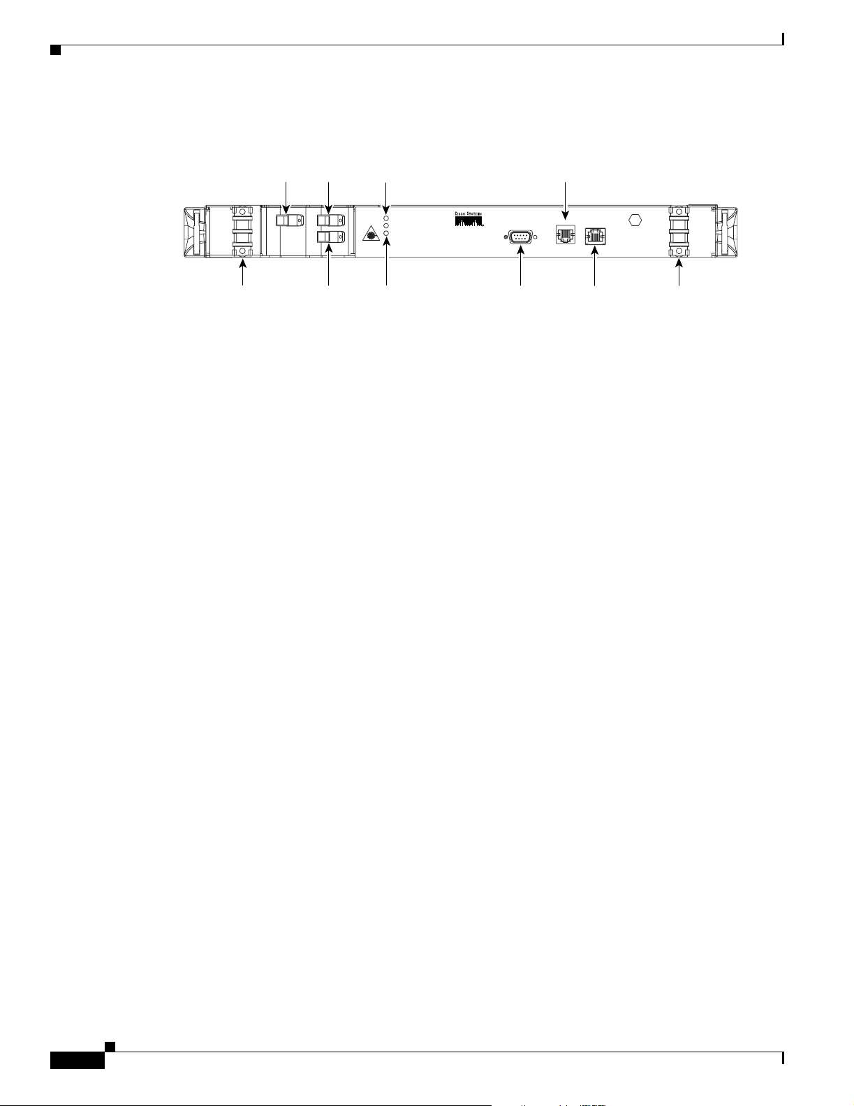
Set Alarm Thresholds
Chapter 4 Provisioning Using ASH and SNMP
FINAL DRAFT - CISCO CONFIDENTIAL
Figure 4-1 ONS 15216 EDFA2 Front Panel
Fiber
Fiber
input
port
output
port
Status
LEDs
Alarm
out
-48V B
RET B
-48V B
R B
71176
-48V A
R A
-48V A
RET A
Fiber
output
monitor
POWER
FAIL
LOS
Power
level
warning
CISCO ONS 15216
(EIA/TIA-232)
RS-232
RS-232
ALARM OUT
LAN
LAN port
LAN LEDs
port
Alarms are reported for the following conditions:
• Loss or degradation of electrical power
• Laser pump overheating, excessive pump current
• Loss or degradation of optical input
Alarms can be connected to a network operations center (NOC) network management system (NMS) via
a network element miscellaneous discrete input and/or office alarm panel/system.
For a full description of alarm threshold command attributes, refer to Chapter 5, “SNMP MIB
Installation and Configuration” or Chapter 6, “ASH Commands.”
To display the alarm thresholds, use the snmp table display local cerent15216EdfaCfgGroup
command (Example 4-8). This command returns the current alarm threshold default values.
Example 4-8 Displaying the Alarm Thresholds
ash:hostname:ONS15216 EDFA2> snmp table display local cerent15216EdfaCfgGroup
CLASS CERENT-15216-EDFA-MIB.cerent15216EdfaCfgGroup ::=
{
cerent15216EdfaCfgSaved = false;
cerent15216EdfaLpoutSetpoint = 0;
cerent15216EdfaLpoutDeviation = 200;
cerent15216EdfaLpoutHysteresis = 100;
cerent15216EdfaLOSThreshold = -2600;
cerent15216EdfaLOSHysteresis = 100;
cerent15216EdfaCtmpMin = -5;
cerent15216EdfaCtmpMinHysteresis = 1;
cerent15216EdfaCtmpMax = 65;
cerent15216EdfaCtmpMaxHysteresis = 1;
cerent15216EdfaCLEI = "";
cerent15216EdfaPowerBusMode = duplex;
cerent15216EdfaPowerBusDCVoltageMin = 410;
cerent15216EdfaPowerBusDCVoltageMax = 560;
};
To set the alarm thresholds, use the snmp row set local cerent15216EdfaCfgGroup command. After
this command is entered, the user is prompted to modify each attribute, row by row, until all attributes
are set. Alarm threshold attributes are described in Table 4-1 on page 4-7.
4-6
Cisco ONS 15216 EDFA2 Operations Guide
78-16033-01
Page 55

Chapter 4 Provisioning Using ASH and SNMP
FINAL DRAFT - CISCO CONFIDENTIAL
Table 4-1 Alarm Threshold Attribute Definitions
Set Alarm Thresholds
Attribute
cerent15216Edfa
CfgSaved
cerent15216Edfa
LpoutSetpoint
cerent15216Edfa
LpoutDeviation
cerent15216Edfa
LpoutHysteresis
cerent15216Edfa
LOSThreshold
Variable
Definition Syntax
Configurati
True Value Read-only Indicates whether the current
on saved
status
Loss of
output
power
Integer
(0 to 1000,
0 default)
setpoint
Loss of
output
power
deviation
Loss of
output
power
hysteresis
Loss of
signal
(input
power)
threshold
Integer
(0 to 1000,
200
default)
Integer
(0 to 1000,
100
default)
Integer
(–3100 to
–1500,
–3000
default)
Maximum
Access Description
configuration has been saved. The value
can be true or false. If false, the
configuration is not saved.
Read-only Can be disregarded when operating
amplifier in Constant Gain Temperature
Compensated mode (manufacturer
default) and Constant Pump Current
mode. Setpoint object is only valid when
amplifier is used in Constant Output
Power and Idle modes.
Read-write Can be disregarded when operating
amplifier in manufacturer default
Constant Gain Temperature
Compensated mode. Deviation object is
only valid when amplifier is used in
Constant Output Power and Idle modes.
Read-write Can be disregarded when operating
amplifier in manufacturer default
Constant Gain Temperature
Compensated mode. Hysteresis object is
only valid when amplifier is used in
Constant Output Power and Idle modes.
Read-write Alarm notifies operations personnel if
the optical input signal of the
ONS 15216 EDFA2 drops below a level
that impacts proper operation of optical
network. Set this attribute at a value that
is appropriate for the intended
application so that the alarm condition is
meaningful. Consult with the Cisco TAC
to determine the threshold value for your
application. As a guideline, Cisco
recommends setting the threshold value
at 3 dBm below the current input power
level of the amplifier. Valid entries are
between –3100 and –1500 in dBm times
100. For example, if the total input power
of the amplifier is –24 dBm and the loss
of input power threshold required is –27
dBm, the loss of input power alarm
threshold is –2700.
78-16033-01
Cisco ONS 15216 EDFA2 Operations Guide
4-7
Page 56

Set Alarm Thresholds
Chapter 4 Provisioning Using ASH and SNMP
FINAL DRAFT - CISCO CONFIDENTIAL
Table 4-1 Alarm Threshold Attribute Definitions (continued)
Attribute
cerent15216Edfa
LOSHysteresis
cerent15216Edfa
CtmpMin
cerent15216Edfa
CtmpMinHystere
sis
Variable
Definition Syntax
Loss of
signal
(input
power)
hysteresis
Minimum
case
temperature
Minimum
case
temperature
hysteresis
Integer
(0 to 1000,
100
default)
Integer
(–10 to 10,
–5 default)
Integer
(0 to 10,
1 default)
Maximum
Access Description
Read-write Used to set the amount the input signal
must increase above the LOS Threshold
level before the alarm is cleared. This
attribute, in conjunction with the loss of
input signal alarm threshold, enables
efficient clearing of alarms. Set this
attribute at a value that is appropriate for
the application so that the alarm
condition will clear when input is stable.
Consult with the Cisco TAC to determine
the correct value for your application. As
a guideline, Cisco recommends setting
the value 1 dB above the LOS Threshold
value. With this setting, the module will
clear the alarm if it detects a signal level
of 1 dB above the current LOS Threshold
value. Valid entries are between 0 and
1000 and are in dB times 100. For
example, if the hysteresis required is 1
dB, the power alarm hysteresis is 100.
Read-write Alarm notifies operations personnel if
the case temperature of the
ONS 15216 EDFA2 drops below a level
that impacts proper operation of the
optical network. The minimum case
temperature should be set at a value that
is appropriate for the intended
application and within product
specifications. Consult with the Cisco
TAC to determine the correct value for
your application. As a guideline, Cisco
recommends that minimum case
temperature be set at 1
are between –10 and 10
Read-write Used to set the amount that the case
temperature of the module must rise
above the minimum case temperature
alarm level before the alarm is cleared.
Set the hysteresis at a value that is
appropriate for the application so that the
alarm condition clears when the input is
stable. Consult with the Cisco TAC to
determine the correct value for your
application. As a guideline, Cisco
recommends that the hysteresis value be
set at 1
°C. Valid entries are between 0
and 10
°C. Setting this value to 0 disables
this option.
°C. Valid entries
°C.
4-8
Cisco ONS 15216 EDFA2 Operations Guide
78-16033-01
Page 57

Chapter 4 Provisioning Using ASH and SNMP
FINAL DRAFT - CISCO CONFIDENTIAL
Table 4-1 Alarm Threshold Attribute Definitions (continued)
Set Alarm Thresholds
Attribute
cerent15216Edfa
CtmpMax
cerent15216Edfa
CtmpMaxHystere
sis
Variable
Definition Syntax
Maximum
case
temperature
Maximum
case
temperature
hysteresis
Integer
(20 to 70,
65 default)
Integer
(0 to 10,
1 default)
Maximum
Access Description
Read-write Alarm notifies operations personnel if
the case temperature of the
ONS 15216 EDFA2 is at a level that may
impact proper operation of the optical
network. Set the maximum case
temperature at a value that is appropriate
for intended application and within
product specifications. Consult with the
Cisco TAC to determine the correct value
for your application. As a guideline,
Cisco recommends that maximum case
temperature value be set at 50
entries are between 20 and 70
Read-write Used to set the amount that the case
temperature of module must drop below
the maximum case temperature alarm
level before the alarm is cleared. Set the
hysteresis at a value that is appropriate
for the application so that the alarm
condition clears when the input is stable.
Consult with the Cisco TAC to determine
the correct value for your application. As
a guideline, Cisco recommends setting
the value at 1
between 0 and 10
0 disables this option.
°C. Valid entries are
°C. Setting this value to
°C. Valid
°C.
78-16033-01
Cisco ONS 15216 EDFA2 Operations Guide
4-9
Page 58

Set Password
Chapter 4 Provisioning Using ASH and SNMP
FINAL DRAFT - CISCO CONFIDENTIAL
Table 4-1 Alarm Threshold Attribute Definitions (continued)
Attribute
cerent15216Edfa
PowerBusDCVolt
ageMin
cerent15216Edfa
PowerBusDCVolt
ageMax
Variable
Definition Syntax
Power bus
minimum
voltage
Power bus
maximum
voltage
Integer
(350 to
700, 400
default)
Integer
(350 to
700, 570
default)
Maximum
Access Description
Read-write Minimum allowable power bus DC
voltage. The default minimum power bus
voltage is set at –40 VDC. Valid entries
are between 350 and 700 and are in
negative volts times 10. For example, if
the voltage required is –40 VDC, the
power bus setting is 400.
The power bus threshold has a 1.0V
tolerance and a 1.0V hysteresis. There is
a potential ±1.5V inaccuracy in the
ONS 15216 EDFA2 voltage
measurement. If the minimum threshold
is configured at 400 (-40 VDC), the
alarm will not raise until the voltage
measures below -39 VDC and will not
clear until the voltage measures above
-41 VDC.
Read-write Maximum allowable power bus DC
voltage. The default maximum power bus
voltage is set at –57 VDC. Valid entries
are between 350 and 700 and are in
negative volts times 10. For example, if
the voltage required is –57 VDC, the
power bus setting is 570.
4.9 Set Password
To restrict access to the ONS 15216 EDFA2, use the user passwd set command to change the default
user password. The password must be a string of up to 10 characters, where at least 2 are non-alphabetic
characters and at least 1 is a special character. With the exception of the administrator access level
(read_write_admin), users can only modify their own passwords. For additional information on user
levels, refer to Table 6-1 on page 6-1. Example 4-9 displays the command.
Example 4-9 Changing Current User’s Password
ash:hostname:ONS15216 EDFA2> user passwd set
The power bus threshold has a 1.0V
tolerance and a 1.0V hysteresis. There is
a potential ±1.5V inaccuracy in the
ONS 15216 EDFA2 voltage
measurement. If the maximum threshold
is configured at 570 (-57 VDC), the
alarm will not raise until the voltage
measures above -58 VDC and will not
clear until the voltage measures below
-56 VDC.
4-10
Cisco ONS 15216 EDFA2 Operations Guide
78-16033-01
Page 59

Chapter 4 Provisioning Using ASH and SNMP
FINAL DRAFT - CISCO CONFIDENTIAL
Password =
****
New Password =
******
Confirm New Password =
******
Note The default user name for the administrator level is CISCO15 with no default password. To start a
session for this user name, press Enter.
4.10 Add Users
Use the user entry create command to add new users to the ONS 15216 EDFA2. The syntax is to enter
the command followed by the user name and then the access level (read, read_write, read_write_admin)
as shown in Example 4-10. The ONS 15216 EDFA2 responds with a request for the password.
Passwords must be an ASCII string of up to 10 characters, where at least 2 are non-alphabetic characters with
at least one special character. Special characters are +, #, and % (defined in Telcordia GR-831-CORE).
Add Users
Example 4-10 Adding a New User
ash:hostname:ONS15216 EDFA2> user entry create janedoe read_write
New Password =
*********
Confirm New Password =
*********
4.11 Save Changes
To ensure that the provisioning changes are set, you must save your changes prior to terminating the
session. To save changes, use the snmp attribute set local cerent15216EdfaOpSaveConfig perform
command (Example 4-11).
Example 4-11 Saving Changes
ash:hostname:ONS15216 EDFA2> snmp attribute set local cerent15216EdfaOpSaveConfig perform
Most SNMP configuration attributes require the above save command before terminating the session
(does not apply to TL1 shell). The exceptions to this save requirement (the attributes that are
automatically saved) are shown below:
• cerent15216EdfaPowerBusMode
• cerent15216EdfaPowerBusDCVoltageMin
78-16033-01
• cerent15216EdfaPowerBusDCVoltageMax
• cerent15216EdfaPumpCfgControlMode and the corresponding pump control value
• cerent15216EdfaConstGainOverallGain
• cerent15216EdfaVariableGainPreAttenuation
• SromIpMgmtGroup attributes:
–
cerent15216EdfaSromIpMgmtEnetAddress
Cisco ONS 15216 EDFA2 Operations Guide
4-11
Page 60

Log Off
4.12 Log Off
Chapter 4 Provisioning Using ASH and SNMP
FINAL DRAFT - CISCO CONFIDENTIAL
–
cerent15216EdfaSromIpMgmtEnetSubNetMask
–
cerent15216EdfaSromIpMgmtDefaultRouterAddress
–
cerent15216EdfaSromIpMgmtHostName
• BootTable attributes:
–
cerent15216EdfaBootModuleIndex
–
cerent15216EdfaBootEntryIndex
–
cerent15216EdfaBootType
–
cerent15216EdfaBootIpAddress
–
cerent15216EdfaBootFileName
At the end of a session, the user must log off of the ONS 15216 EDFA2. To log off, use the logoff
command. This is shown in Example 4-12.
Example 4-12 Logging Off
ash:hostname:ONS15216 EDFA2> logoff
4.13 Back Up System Configuration
The configuration information for the ONS 15216 EDFA2 can be saved in a file for later use or to
configure other ONS 15216 EDFA2 units. This file contains manufacturing information about the unit
that is being backed up (such as part number and serial number), setup information for the unit (such as
IP address and host name), all configuration information (such as alarm thresholds and pump mode), and
the user database.
The backup file is saved with cyclic redundancy code (CRC) to ensure data integrity, and the user names,
passwords, and other system settings are encrypted for security. The file header, which identifies the
node name, IP address, and software version, is text readable. Only the configuration information and
user database are copied back to the ONS 15216 EDFA2 during a restore.
Step 1 Back up the system configuration to a file on the FFS.
ash:hostname:ONS15216 EDFA2> backup system filename
The system responds with progress information:
Trying to Backup the system configuration to file filename...
Backup SNMP Data...
DONE!...
Backup NON-SNMP Config...
DONE!...
Backup USER/PASSWD Accts...
DONE!...
CRC = 6cce1bd9
Backup DONE!
4-12
Cisco ONS 15216 EDFA2 Operations Guide
78-16033-01
Page 61

Chapter 4 Provisioning Using ASH and SNMP
FINAL DRAFT - CISCO CONFIDENTIAL
Step 2 If desired, use FTP to copy the file to a remote server. See “Example of FTP to a Remote Server” section
on page 7-2.
4.14 Restore System Configuration
The configuration information for the ONS 15216 EDFA2 can be restored form a file. During this
process, all configuration information (such as alarm thresholds and pump mode) and the user database
from the file are replaced in the ONS 15216 EDFA2 memory and FFS.
Before the restore begins, a cyclic redundancy code (CRC) check is performed to ensure data integrity.
Step 1 If desired, use FTP to copy a system configuration file from a remote server to the ONS 15216 EDFA2
FFS. See “Example of FTP from a Remote Server” section on page 7-1.
Step 2 Restore the system configuration from the file on the FFS.
ash:hostname:ONS15216 EDFA2> restore system filename
Restore System Configuration
The system responds with progress information:
Restoring the system configuration from file filename...
CRC Check OK
Restore SNMP Configuration...
...............
DONE!...
Restore NON SNMP Configuration...
user inactivity modify read_write_admin 15
user inactivity modify read_write 30
user inactivity modify read 60
shell type modify ash
tl1 sid modify foo
manufacturer keep_alive modify -idle 1 -interval 75 -retries 9
snmp attribute set local cerent15216EdfaSromIpMgmtHostName "newhostname"
DONE!...
Restore USER INFO...
DONE!...
Restore DONE!
Step 3 Save the changes.
ash:hostname:ONS15216 EDFA2> snmp attribute set local cerent15216EdfaOpSaveConfig perform
Step 4 Reboot the ONS 15216 EDFA2.
ash:hostname:ONS15216 EDFA2> processor reset
After the processor reboots, user names and passwords from the new user database must be used for
access.
78-16033-01
Cisco ONS 15216 EDFA2 Operations Guide
4-13
Page 62

Recover Default Password
FINAL DRAFT - CISCO CONFIDENTIAL
4.15 Recover Default Password
If the root password for CISCO15 is lost, there is a procedure to reset it to regain full administrative
control of the ONS 15216 EDFA2. The user must be connected to the ONS 15216 EDFA2 by serial
communication, perform a hard power reset, and then performs a series of commands within 60 seconds
of rebooting, according to the following procedure. This procedure resets the default user password only;
no other settings are affected.
Chapter 4 Provisioning Using ASH and SNMP
Warning
Note If the ONS 15216 EDFA2 firmware is not version 2.3.14 or greater, the CISCO15 user resets to
The ONS 15216 EDFA2 ceases its optical amplification function when power is off during this process.
Traffic should be rerouted before this procedure begins.
read_write access level, not read_write_admin, which has full administrative control. Contact Cisco
TAC for assistance.
Step 1 Connect to the RS-232 (EIA/TIA-232) port.
Step 2 Open HyperTerminal. (HyperTerminal can be found in the Microsoft Windows Accessories menu.)
Step 3 Perform hard power reset of the ONS 15216 EDFA2 (disconnect and reconnect power).
Step 4 While the dots are present in the HyperTerminal window during the reboot process, enter Ctrl C on the
keyboard.
The ONS 15216 EDFA2 should boot from the firmware image. The prompt is %.
Step 5 At the hostname prompt, enter the following command (must be done within 60 seconds of rebooting):
hostname:edfaboot% user passwd set CISCO15 default
Step 6 At the hostname prompt, enter the following command:
hostname:edfaboot% login CISCO15
Password =
<enter>
4-14
Step 7 At the hostname prompt, enter the following command:
hostname:edfaboot% processor reset
After the processor reset, the default CISCO15 login password will be the default (the Enter key).
Cisco ONS 15216 EDFA2 Operations Guide
78-16033-01
Page 63

FINAL DRAFT - CISCO CONFIDENTIAL
SNMP MIB Installation and Configuration
This chapter explains how to read and understand SNMP MIB as it relates to the Cisco
ONS 15216 EDFA2. This chapter is a reference of all ONS 15216 EDFA2 SNMP commands that are
used in a network management system (NMS). For provisioning the ONS 15216 EDFA2, see Chapter 4,
“Provisioning Using ASH and SNMP”.
5.1 SNMP Overview
Simple Network Management Protocol (SNMP) is an application-layer communication protocol that
allows network devices to retrieve and modify the value of management information, as well as provide
event notification to a NMS.
The ONS 15216 EDFA2 SNMP implementation uses proprietary and standard Internet Engineering Task
Force (IETF) MIBs to convey inventory, fault, and performance management information.
SNMP allows limited management of the ONS 15216 EDFA2 by a generic, third-party SNMP manager
(for example, HP OpenView Network Node manager [NNM] or Open Systems Interconnection [OSI]
NetExpert).
CHAPTER
5
The ONS 15216 EDFA2 supports SNMP Version 1 (SNMPv1) and SNMP Version 2c (SNMPv2c)
protocols.
5.1.1 SNMP Components
An SNMP-managed network consists of three primary components:
• Managed devices
• Agents
• Management systems
A managed device is a network node that contains an SNMP agent and resides on an SNMP-managed
network. Managed devices collect and store management information and use SNMP to make this
information available to management systems that use SNMP. Managed devices include routers, access
servers, switches, bridges, hubs, computer hosts, and network elements such as the ONS 15216 EDFA2.
78-16033-01
Cisco ONS 15216 EDFA2 Operations Guide
5-1
Page 64
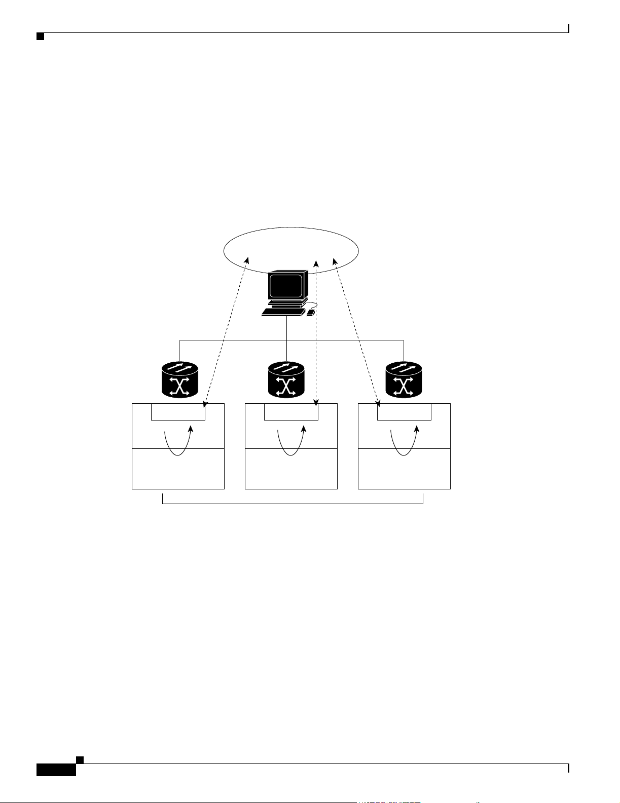
SNMP Overview
FINAL DRAFT - CISCO CONFIDENTIAL
5.1.2 ONS 15216 EDFA2 SNMP Elements
The following three SNMP elements are used with the ONS 15216 EDFA2:
• SNMP agent
• SNMP MIB
• SNMP manager
The SNMP elements are shown in Figure 5-1.
Figure 5-1 SNMP Elements
Management
Entity
Chapter 5 SNMP MIB Installation and Configuration
5.1.2.1 SNMP Agent
An agent is an entity that assumes an operation role to receive, process, and respond to requests, as well
as generated event reports. The SNMP agent gathers data from the MIB, which is the repository for
device parameter and network data. To respond to requests, the agent must have network management
information access. To generate reports, an agent must be notified of internal events.
Agent
Management
Database
NMS
Agent
Management
Database
Managed Devices
Agent
Management
Database
33930
5-2
Cisco provides both an SNMP agent (installed on the ONS 15216 EDFA2) and SNMP MIB to monitor
the ONS 15216 EDFA2. The SNMP agent software and MIB are pre-installed on each module.
Figure 5-2 on page 5-3 shows the relationship between the SNMP agent and the MIB.
Cisco ONS 15216 EDFA2 Operations Guide
78-16033-01
Page 65

Chapter 5 SNMP MIB Installation and Configuration
FINAL DRAFT - CISCO CONFIDENTIAL
Figure 5-2 SNMP Agent and MIB
SNMP Overview
NMS
SNMP Manager
5.1.2.2 SNMP MIB
The SNMP MIBs (CERENT-15216-EDFA-MIB.mib and CERENT-GLOBAL-REGISTRY.mib) are files
written in ASN.1 syntax. The CERENT-15216-EDFA-MIB.mib specifies what ONS 15216 EDFA2
information needs to be controlled and monitored. This MIB is pre-installed on the SNMP agent and is
accessible via the CLI.
The CERENT-15216-EDFA-MIB.mib and other MIBs can also be installed on a third-party SNMP
manager located at a network management center. The SNMP manager at the network management
center or the SNMP manager, accessible via the CLI, (see SNMP Manager) uses the SNMP MIBs to
communicate with the SNMP agent.
5.1.2.3 SNMP Manager
The ONS 15216 EDFA2 comes with a pre-installed SNMP manager accessible via the CLI. This SNMP
manager can be accessed and used to communicate with the SNMP agent that is also pre-installed on
each ONS 15216 EDFA2. This manual displays examples of issuing SNMP commands to the amplifier
using the built-in SNMP manager.
get, get-next, get-bulk
get-response, traps
Network device
MIB
SNMP Agent
32632
5.1.2.3.1 Third-party, Vendor-Specific SNMP Managers
SNMP managers from third-party vendors running on a separate computer located at a network
management center are often used to manage network elements. If a third-party SNMP manager is used,
it must be able to communicate with the SNMP agent pre-installed on the ONS 15216 EDFA2.
If a third-party SNMP manager is used, it is assumed that the SNMP manager is pre-installed prior to
the SNMP MIB installation. Each vendor-specific SNMP manager has an unique set of instructions for
SNMP MIB installation. For directions on loading the SNMP MIBs, refer to SNMP manager
documentation.
Cisco does not provide or recommend a standard third-party SNMP manager.
5.1.3 SNMP MIBs and Message Types
SNMP operations can be quite powerful. A manager can retrieve or modify the value of management
information accessible by an agent, an agent can report an event to a manager, and the manager can
inform another manager of the value of management information on an agent. Using retrieval and
modification operations, a manager can cause an agent to perform an action or execute a command. The
manager can also create new and delete existing instances of management information.
A MIB is a hierarchically-organized collection of information. Network management protocols, such as
SNMP, gain access to these MIBs. MIBs consist of managed objects and are identified by object
identifiers (OID).
78-16033-01
Cisco ONS 15216 EDFA2 Operations Guide
5-3
Page 66

SNMP Overview
Chapter 5 SNMP MIB Installation and Configuration
FINAL DRAFT - CISCO CONFIDENTIAL
The ONS 15216 EDFA2 SNMP agent communicates with an SNMP management application (a
third-party application or the built-in SNMP manager) using SNMP messages. Table 5- 1 describes
SNMP operation types.
Table 5-1 SNMP Operation Types
Operation Description
get-request Retrieves a value from a specific variable.
get-next-request Retrieves the value following the named variable; this operation is often used
to retrieve variables in a table. With this operation, an SNMP agent does not
need to know the exact variable name. The SNMP manager searches
sequentially to find the needed variable in the MIB.
get-response The reply to a get-request, get-next-request, get-bulk-request, or set-request
sent by an NMS.
get-bulk-request Similar to a get-next-request, but this operation fills the get-response with up
to the max-repetition number of get-next interactions.
trap An unsolicited message sent by an SNMP agent to an SNMP manager
indicating that an event has occurred.
set-request Sets a value of a specific variable.
5.1.4 Command Syntax Using the SNMP Agent
Although Cisco has its own separate SNMP manager (Cisco Transport Manager [CTM]), management
of the ONS 15216 EDFA2 is also possible using the built-in SNMP manager via the command line in the
ASH shell, as described in SNMP Commands, page 6-15. The example commands and command syntax
described in this manual are based on using the built-in ONS 15216 EDFA2 SNMP manager through the
ASH shell CLI.
Commands can be issued via Telnet over a LAN or directly through the RS-232 (EIA/TIA-232) port on
the module. (See .) After setting up a connection to the module and entering a password and user name,
the following prompt appears:
ash:hostname:ONS15216 EDFA2>
To communicate with the module using SNMP, the command must begin with “snmp”.
Note To view a list of possible SNMP operations, enter “snmp” followed by a space and press the Tab key.
(See Example 5-1.)
Example 5-1 snmp Command Followed by the Tab Key
ash:hostname:ONS15216 EDFA2> snmp
agent
attribute
host
mib
pdu
row
session
subtree
table
trap
5-4
Cisco ONS 15216 EDFA2 Operations Guide
78-16033-01
Page 67

Chapter 5 SNMP MIB Installation and Configuration
FINAL DRAFT - CISCO CONFIDENTIAL
tree
Continue to enter operations from the list until the complete command is created. (See Example 5-2.)
Example 5-2 snmp table display Command
ash:hostname:ONS15216 EDFA2> snmp table display local cerent
cerent15216EdfaCommunityEntry
cerent15216EdfaCommTrapEntry
cerent15216EdfaViewEntry
cerent15216EdfaAgentControlGroup
cerent15216EdfaActionOpGroup
cerent15216EdfaLogEventControl
cerent15216EdfaLogEventEntry
cerent15216EdfaBootEntry
cerent15216EdfaBootImageEntry
cerent15216EdfaRtcDateAndTime
cerent15216EdfaSromIpMgmtGroup
cerent15216EdfaSromRingGroup
cerent15216EdfaCfgGroup
cerent15216EdfaOverallControl
cerent15216EdfaPumpCfgEntry
cerent15216EdfaOverallStatusGroup
cerent15216EdfaPumpStatusEntry
cerent15216EdfaAlarmEntry
cerent15216EdfaVersionGroup
cerent15216EdfaOpGroup
ash:hostname:ONS15216 EDFA2> snmp table display local cerent15216Edfa
Enabling SNMP Remote Management Community Strings
Use these commands to set up community strings (Enabling SNMP Remote Management Community
Strings, page 5-5) and traps (Setting Up Traps, page 5-21).
5.2 Enabling SNMP Remote Management Community Strings
SNMP communities are groupings of workstations and servers (or gateways) that can manage the
ONS 15216 EDFA2. NMSs use SNMP communities to enforce security. SNMP enforces security
through password-like community strings. Access to the SNMP agent and the ONS 15216 EDFA2 can
be limited by both IP address and community string.
The CLI SNMP manager (local SNMP manager) must be used to setup remote management (via a Telnet
connection or terminal server). A third-party, vendor-specific SNMP manager cannot be used to setup
remote management.
The process for setting up community entries consists of:
• Creating a View, page 5-6
• Creating a Community Entry, page 5-7
The ONS 15216 EDFA2 has the two default community strings listed in Tab le 5 -2 .
Table 5-2 Default Community Strings
Community String Default Privileges
public read operations for all MIBs
private read and write operations for all MIBs
78-16033-01
Cisco ONS 15216 EDFA2 Operations Guide
5-5
Page 68

Chapter 5 SNMP MIB Installation and Configuration
Enabling SNMP Remote Management Community Strings
FINAL DRAFT - CISCO CONFIDENTIAL
The privileges assigned to the default strings can be modified or new communities with custom
privileges can be created.
5.2.1 Creating a View
The following command describes how to set a view entry. A view defines and restricts the MIB
attributes that a particular community can access. The view entry and the community entry are set to
factory defaults. Users should consult with the Cisco TAC before modifying these settings.
5.2.1.1 Set View Entry
Command snmp row set local cerent15216EdfaViewEntry
Syntax Description snmp row set local cerent15216EdfaViewEntry view_index_# subtree
To create a community entry, a view must first be created. A MIB view can restrict the MIBs that a
particular community can access. To create a view, type the command. view_index_# is an integer (1 to
2048) assigned to this view entry and subtree is the MIB subtree to which this view applies. Multiple
view entries can be used for each view index.
This
command creates a new row in the ViewEntry table. The SNMP manager prompts the user for each
attribute.
To display a list of possible values, press the Spacebar followed by the Tab key. (See Example 5-3.)
Example 5-3 cerent15216EdfaViewEntry Set Command
ash:hostname:ONS15216 EDFA2> snmp row set local cerent15216EdfaViewEntry 1 cerent
cerent15216EdfaViewMask '0'H
cerent15216EdfaViewType included
cerent15216EdfaViewStatus
active
notInService
notReady
createAndGo
createAndWait
destroy
cerent15216EdfaViewStatus createAndGo
ash:hostname:ONS15216 EDFA2> snmp row display local cerent15216EdfaViewEntry 1 sample
CLASS cerent15216Edfa-AGENT-MIB.cerent15216EdfaViewEntry ::=
{
cerent15216EdfaViewIndex = 1;
cerent15216EdfaViewSubtree = { sample };
cerent15216EdfaViewMask = '00'H;
cerent15216EdfaViewType = included;
cerent15216EdfaViewStatus = active;
Access to the ONS 15216 EDFA2 can be restricted by IP address or community string using this
command.
Table 5-3 on page 5-7 describes the command and MIB view prompts.
5-6
Cisco ONS 15216 EDFA2 Operations Guide
78-16033-01
Page 69

Chapter 5 SNMP MIB Installation and Configuration
FINAL DRAFT - CISCO CONFIDENTIAL
Table 5-3 Creating a View
Data Prompt Command Description
cerent15216EdfaViewIndex snmp row set local
cerent15216EdfaViewSubTree Sub-Tree Object Identifier Sub-Tree Object Identifier: An
cerent15216EdfaViewMask ‘0’H A bit mask that identifies objects in
cerent15216EdfaViewType included A flag that specifies the status of the
cerent15216EdfaViewStatus createAndGo If the entry currently exists, use
Enabling SNMP Remote Management Community Strings
cerent15216EdfaViewEntry 1
zeroDotZero
View Index: A unique value for each
MIB view.
This value is the number entered
with the command.
object identifier that designates a
sub-tree element in the MIB
hierarchy. zeroDotZero specifies the
entire CLI MIB hierarchy.
the subtree.
view. Valid entries are included and
excluded.
active. (CreateAndGo cannot be
used if any entry exists.)
5.2.2 Creating a Community Entry
SNMP communities are groupings of workstations and servers (or gateways) that can manage the
ONS 15216 EDFA2. NMSs use SNMP communities to enforce security. Because access to the SNMP
agent is controlled by a community entry, every SNMP agent must be configured to recognize one or
more community names, and to provide the appropriate level of access to managers according to the
community name. The following commands describe the commands for displaying or setting community
entries. Users should consult with the Cisco TAC before modifying these settings.
5.2.2.1 Set CommunityEntry
Command snmp row set local cerent15216EdfaCommunityEntry
Syntax Description snmp row set local cerent15216EdfaCommunityEntry community_index_#
After creating a view, use the snmp row set local cerent15216EdfaCommunityEntry command to
create a community entry for that view.
The SNMP manager prompts the user for each attribute. Press the Spacebar and then the Tab key after
a prompt to view possible data inputs (Example 5-4). Refer to Table 5-4 on page 5-8 for information
concerning data for each prompt.
78-16033-01
Example 5-4 cerent15216EdfaCommunityEntry Set Command
ash:hostname:ONS15216 EDFA2> snmp row set local cerent15216EdfaCommunityEntry 3
Cisco ONS 15216 EDFA2 Operations Guide
5-7
Page 70

Enabling SNMP Remote Management Community Strings
FINAL DRAFT - CISCO CONFIDENTIAL
cerent15216EdfaCommName ""
cerent15216EdfaCommViewIndex 0
cerent15216EdfaCommPrivileges 35
cerent15216EdfaCommSrcIPAddr 0.0.0.0
cerent15216EdfaCommNetMask 0.0.0.0
cerent15216EdfaCommStatus 0
cerent15216EdfaCommStatus OBJECT-TYPE
SYNTAX INTEGER
{
active(1),
notInService(2),
notReady(3),
createAndGo(4),
createAndWait(5),
destroy(6)
}
MAX-ACCESS read-create
DESCRIPTION
::= { cerent15216EdfaCommunityEntry 7 }
Table 5-4 displays the definitions for the community entry values.
Table 5-4 Creating a Community Entry
Chapter 5 SNMP MIB Installation and Configuration
Data Prompt Description
cerent15216EdfaCommIndex Community Index: An index that uniquely identifies a
particular SNMP community. This community index is part of
the command. In Example 5-4 on page 5-7, it is “3”.
cerent15216EdfaCommName Community Name: The community string.
cerent15216EdfaCommViewIndex View Index: The view index specifies which MIBs this
particular community string can access.
cerent15216EdfaCommPrivileges Privileges: A bitmap of access privileges that govern what
management operations a particular community can perform.
These privileges are expressed as a sum of values, where each
value represents a particular operation. Refer to Table 5-5 on
page 5-9 for the SNMP Operation Decimal Values.
cerent15216EdfaCommSrcIPAddr Source IP Address: The IP address from which network
management traffic for this community originates.
cerent15216EdfaCommNetMask NetMask: The subnet mask for the source IP address.
cerent15216EdfaCommStatus Status: The status of this conceptual row in the community
table.Use createAndGo to create a new row. Use active to
modify an existing row.
5-8
Cisco ONS 15216 EDFA2 Operations Guide
78-16033-01
Page 71

Chapter 5 SNMP MIB Installation and Configuration
Enabling SNMP Remote Management Community Strings
FINAL DRAFT - CISCO CONFIDENTIAL
5.2.2.2 Display CommunityEntry
Command snmp row display local cerent15216EdfaCommunityEntry
Syntax Description snmp row display local cerent15216EdfaCommunityEntry community_index_#
After creating a community string, use this command to view its parameters. The number in the
command refers to the community index number created in the previous section.
Example 5-5 cerent15216EdfaCommunityEntry Display Command
ash:hostname:ONS15216 EDFA2> snmp row display local cerent15216EdfaCommunityEntry 1
CLASS cerent15216Edfa-AGENT-MIB.cerent15216EdfaCommunityEntry ::=
{
cerent15216EdfaCommIndex = 1;
cerent15216EdfaCommName = "private";
cerent15216EdfaCommViewIndex = 1;
cerent15216EdfaCommPrivileges = 255;
cerent15216EdfaCommSrcIPAddr = 0.0.0.0;
cerent15216EdfaCommNetMask = 255.255.255.255;
cerent15216EdfaCommStatus = active;
};
Table 5-5 displays the decimal values for the following SNMP operations.
Table 5-5 SNMP Operation Decimal Values
SNMP Operation Decimal Values
Get 1
GetNext 2
Response (enable for all community strings) 4
Set 8
SNMPv1-Trap 16
GetBulk 32
Inform (enable for all community strings) 64
SNMPv2-Trap (enable for all community strings) 128
For example, 255 is the sum of all decimal values and specifies access to all SNMP operations. This sum
is the default private community. 247 is the sum for all SNMP operations with the exception of the Set
operation. This sum is the default public community.
78-16033-01
Cisco ONS 15216 EDFA2 Operations Guide
5-9
Page 72

Setup for CTM Access
FINAL DRAFT - CISCO CONFIDENTIAL
5.3 Setup for CTM Access
Use the following procedure to configure a new ONS 15216 EDFA2 for Cisco Transport Manager
(CTM) access:
Step 1 Log into the serial port. Use 19,000 bps, 8 bits, no parity, 1 stop, and no flow control over a
male-to-female straight 9-pin cable.
Amp01:ONS15216 EDFA2> ACT-USER::CISCO15:123::;
Step 2 Set the default user password to admin15##:
Amp01:ONS15216 EDFA2> ED-PID::CISCO15:124::,admin15##;
Step 3 Enter the IP address and node name configuration information:
Amp01:ONS15216 EDFA2> ED-NE-GEN:::125:::NAME= , IPADDR= , IPMASK= , DEFRTR= ;
Step 4 Set the date and time:
Amp01:ONS15216 EDFA2> ED-DAT:::126::2003-06-18,08-49-00;
Chapter 5 SNMP MIB Installation and Configuration
Step 5 Activate the new IP address by rebooting:
Amp01:ONS15216 EDFA2> INIT-SYS::ALL:127::1;
Step 6 Telnet to the ASH shell by typing the following:
telnet <ONS 15216 EDFA2 IP address> 8023
Step 7 Login using the user name CISCO15 and the password admin15##.
Step 8 Enter the community information:
ash:hostname:ONS15216 EDFA2> snmp row set local cerent15216EdfaCommunityEntry 2 (Do not
use Entry 1 which is the RO public community)
cerent15216EdfaCommIndex = 2 (if the CommunityEntry is 2)
cerent15216EdfaCommName = "private" (must match the CTM community string entry)
cerent15216EdfaCommViewIndex = 1
cerent15216EdfaCommPrivileges = 255
cerent15216EdfaCommSrcIPAddr = 0.0.0.0 (for more security, enter CTM A's IP address)
cerent15216EdfaCommNetMask = 255.255.255.255
cerent15216EdfaCommStatus = 4
(active(1),notInService(2),notReady(3),createAndGo(4),createAndWait(5),destroy(6))
ash:hostname:ONS15216 EDFA2> snmp row set local cerent15216EdfaCommunityEntry 3
cerent15216EdfaCommIndex = 3 (if the CommunityEntry is 3)
cerent15216EdfaCommName = "private" (must match the CTM community string entry)
cerent15216EdfaCommViewIndex = 1
cerent15216EdfaCommPrivileges = 255
cerent15216EdfaCommSrcIPAddr = 0.0.0.0 (for more security, enter CTM B's IP address)
cerent15216EdfaCommNetMask = 255.255.255.255
cerent15216EdfaCommStatus = 4
(active(1),notInService(2),notReady(3),createAndGo(4),createAndWait(5),destroy(6))
5-10
Step 9 Verify the community information:
ash:hostname:ONS15216 EDFA2> snmp table display local cerent15216EdfaCommunityEntry
Step 10 Enter the trap destination information:
ash:hostname:ONS15216 EDFA2> snmp row set local cerent15216EdfaCommTrapEntry 1
Cisco ONS 15216 EDFA2 Operations Guide
78-16033-01
Page 73

Chapter 5 SNMP MIB Installation and Configuration
FINAL DRAFT - CISCO CONFIDENTIAL
cerent15216EdfaCommTrapCommunity "private"
cerent15216EdfaCommTrapDestIPAddress <CTM A's IP address>
cerent15216EdfaCommTrapDestUDPPort 162
cerent15216EdfaCommTrapViewIndex 1
cerent15216EdfaCommTrapVersion v2
cerent15216EdfaCommTrapStatus 4
ash:hostname:ONS15216 EDFA2> snmp row set local cerent15216EdfaCommTrapEntry 2
cerent15216EdfaCommTrapCommunity "private"
cerent15216EdfaCommTrapDestIPAddress <CTM B's IP address>
cerent15216EdfaCommTrapDestUDPPort 162
cerent15216EdfaCommTrapViewIndex 1
cerent15216EdfaCommTrapVersion v2
cerent15216EdfaCommTrapStatus 4
Step 11 Verify the trap destination information:
ash:hostname:ONS15216 EDFA2> snmp table display local cerent15216EdfaCommTrapEntry
Step 12 Enable traps:
ash:hostname:ONS15216 EDFA2> snmp attribute set local cerent15216EdfaAgentTrapEnable 1
Tables and Groups
Step 13 Verify that traps are enabled:
ash:hostname:ONS15216 EDFA2> snmp attribute get local cerent15216EdfaAgentTrapEnable
Step 14 Set network element (NE) ID:
ash:hostname:ONS15216 EDFA2> snmp attribute set local sysName <NE ID>
Step 15 Save the new settings:
ash:hostname:ONS15216 EDFA2> snmp attribute set local cerent15216EdfaActionOpSaveConfig
perform
Step 16 Log off:
ash:hostname:ONS15216 EDFA2> logoff
5.4 Tables and Groups
The cerent15216Edfa.mib contains several key tables that are used to review and provision the
ONS 15216 EDFA2. The following tables are listed and described in the following sections:
• CfgGroup Table, page 5-12
• PumpCfgEntry Table, page 5-14
• OverallStatusGroup Table, page 5-16
• OverallControl Table, page 5-18
78-16033-01
• PumpStatusEntry Table, page 5-18
• AlarmEntry Table, page 5-19
• OpGroup Table, page 5-20
• VersionGroup Table, page 5-21
Cisco ONS 15216 EDFA2 Operations Guide
5-11
Page 74

Tables and Groups
FINAL DRAFT - CISCO CONFIDENTIAL
5.4.1 CfgGroup Table
The cerent15216EdfaCfgGroup table is used to set or get alarm threshold configuration. The associated
table command provides a summary of all alarm thresholds. See Table 5- 6 for variable definitions. For
more information on alarm thresholds, see the “Set Alarm Thresholds” section on page 4-5.
Table 5-6 cerent15216EdfaCfgGroup Variable Descriptions
Variable Syntax
cerent15216EdfaCfgSaved True Value Read-only Indicates whether the current
cerent15216EdfaLpoutSetp
oint
cerent15216EdfaLpoutDevi
ation
cerent15216EdfaLpoutHyst
eresis
cerent15216EdfaLOSThres
hold
cerent15216EdfaLOSHyster
esis
cerent15216EdfaCtmpMin Integer
cerent15216EdfaCtmpMinH
ysteresis
cerent15216EdfaCtmpMax Integer
cerent15216EdfaCtmpMax
Hysteresis
Integer
(0 to 1000)
Integer
(0 to 1000)
Integer
(0 to 1000)
Integer
(–3100 to –1500)
Integer
(0 to 1000)
(–10 to 10)
Integer
(0 to 10)
(20 to 70)
Integer
(0 to 10)
Chapter 5 SNMP MIB Installation and Configuration
Maximum
Access Description
configuration has been saved.
Read-only Loss of pump output power set point
for the Lpout alarm (*10 mW).
This is set when the
cerent15216EdfaPumpCfgConstOutP
ower attribute is set for pump 2.
Read-write Amount that the output power must
deviate from the set point to set the
Lpout alarm (*100 dB).
Read-write Amount that the output power must
move towards the set point before the
Lpout alarm is cleared (*100 dB).
Read-write Loss of signal threshold (*100 dBm).
Read-write Amount above
cerent15216EdfaLOSThreshold that
the input signal must rise before the
Lpin alarm is cleared (*100 dB).
Read-write Minimum allowable case temperature
in degrees Celsius.
Read-write Amount above
cerent15216EdfaCtmpMin that the
case temperature must rise before the
Ctmp alarm is cleared in degrees
Celsius.
Read-write Maximum allowable case temperature
in degrees Celsius.
Read-write Amount below
cerent15216EdfaCtmpMax that the
case temperature must drop before the
Ctmp alarm is cleared in degrees
Celsius.
5-12
Cisco ONS 15216 EDFA2 Operations Guide
78-16033-01
Page 75

Chapter 5 SNMP MIB Installation and Configuration
FINAL DRAFT - CISCO CONFIDENTIAL
Table 5-6 cerent15216EdfaCfgGroup Variable Descriptions (continued)
Variable Syntax
cerent15216EdfaCLEI Display String
cerent15216EdfaPowerBus
Mode
cerent15216EdfaPowerBus
DCVoltageMin
cerent15216EdfaPowerBus
DCVoltageMax
(0 to 10
characters)
cerent15216Edfa
PowerBusMode
Integer
(350 to 700)
Integer
(350 to 700)
Tables and Groups
Maximum
Access Description
Read-only Indicates the factory setting of the
Common Language Equipment
Identifier (CLEI) code (established by
Telcordia) of the Cisco
ONS 15216 EDFA2. This attribute
can be accessed but not changed by
the user.
Read-write Simplex for one power source (Bus
A) or duplex for redundant power
source (Bus A and Bus B) Power Bus
mode.
Read-write Minimum allowable power bus DC
voltage. The default maximum power
bus voltage is set at –40 VDC. Valid
entries are between 350 and 700 and
are in negative volts times 10. For
example, if the voltage required is –40
VDC, the power bus setting is 400.
The power bus threshold has a 1.0V
tolerance and a 1.0V hysteresis. If the
minimum threshold is configured at
400 (-40 VDC), the alarm will not
raise until the voltage goes below -39
VDC and will not clear until the
voltage goes above -41 VDC.
Read-write Maximum allowable power bus DC
voltage. The default maximum power
bus voltage is set at –57 VDC. Valid
entries are between 350 and 700 and
are in negative volts times 10. For
example, if the voltage required is –57
VDC, the power bus setting is 570.
The power bus threshold has a 1.0V
tolerance and a 1.0V hysteresis. If the
maximum threshold is configured at
570 (-57 VDC), the alarm will not
raise until the voltage goes above -58
VDC and will not clear until the
voltage goes below -56 VDC.
78-16033-01
Use the snmp attribute set local cerent15216EdfaOpSaveConfig perform command to save changes.
Cisco ONS 15216 EDFA2 Operations Guide
5-13
Page 76

Tables and Groups
FINAL DRAFT - CISCO CONFIDENTIAL
5.4.2 PumpCfgEntry Table
The cerent15216EdfaPumpCfgEntry table is used to set or get laser pump control mode configuration.
The associated table command displays a settings summary or allows you to set pumps. See Tabl e 5-7
for variable definitions. The factory default pump control mode for the ONS 15216 EDFA2 is Constant
Gain Temperature Compensated. Cisco recommends that users contact the Cisco TAC prior to changing
this mode of operation.
Table 5-7 cerent15216EdfaPumpCfgEntry Variable Descriptions
Variable Syntax
cerent15216EdfaPumpCfgP
umpNum
cerent15216EdfaPumpCfgC
ontrolMode
cerent15216EdfaPumpCfgC
onstPumpCurrent
cerent15216EdfaPumpCfgC
onstPumpPower
cerent15216EdfaPumpCfgC
onstOutPower
Chapter 5 SNMP MIB Installation and Configuration
Maximum
Access Description
cerent15216Edfa
PumpNumber
cerent15216Edfa
ControlMode
Integer (0 to 300) Read-write Constant pump current (mA).
Integer (0 to 100) Read-write Constant pump power (mW). The
Integer (0 to 650) Read-write Constant output power (*10 mW). The
Not
Accessible
Read-write Laser pump control mode. When the
Laser pump number (1 or 2).
mode is set directly to constCurrent,
constPower, or constOutputPower, the
current value of ConstPumpCurrent,
ConstPumpPower, or ConstOutPower
is used as the constant parameter for
the new mode.
The current that is used when the
pump control mode is changed to
constCurrent.
power that is used when the control
mode is changed to constPumpPower.
power that is used when the control
mode is changed to
constOutputPower.
5.4.2.1 Changing the Pump Control Mode
For Constant Gain Temperature Compensated mode, the system automatically sets the second pump to
this mode when either pump is set.
Constant Output Power mode is only valid for pump 2. If pump 2 is set to Constant Output Power Mode,
pump 1 is automatically set to Constant Pump Power mode with a value of 75 mW.
For Constant Pump Current or Constant Pump Power mode, the user should set both pump modes to be
the same.
Warning
Cisco ONS 15216 EDFA2 Operations Guide
5-14
The pump control modes Constant Pump Current, Constant Pump Power, and Constant Output Power
are to be used with very high precautions. They are service affecting and can reduce the life cycle of
the lasers if used in extreme conditions. The factory default setting and recommended mode of
operation is Constant Gain Temperature Compensated mode. Cisco recommends that users contact
the Cisco TAC before changing from this mode of operation.
78-16033-01
Page 77

Chapter 5 SNMP MIB Installation and Configuration
FINAL DRAFT - CISCO CONFIDENTIAL
To set the ONS 15216 EDFA2 to Constant Pump Current mode, use the following steps:
Step 1 Set the pump value using cerent15216EdfaPumpCfgConstPumpCurrent attribute.
a. Select pump 1.
b. Set the value.
Step 2 Repeat Step 1 for pump 2.
Step 3 Set the pump mode of operation using cerent15216EdfaPumpCfgControlMode attribute.
a. Select pump 1.
b. Set the mode.
Step 4 Repeat Step 3 for pump 2.
Example 5-6 shows how to set the ONS 15216 EDFA2 to Constant Pump Current mode and then set it
back to Constant Gain Temperature Compensated mode. (Setting pump 1 or 2 to Constant Gain
Temperature Compensated mode sets both pumps to that mode.)
Example 5-6 Setting Mode to Constant Pump Current and then Back to Constant Gain Temperature
Compensated
Tables and Groups
ash:
hostname:
200
ash:
hostname:
200
ash:
hostname:
constGainTempComp
constOutputPower
constCurrent
constPower
idle
hostname:
ash:
constCurrent
hostname:
ash:
constCurrent
ash:
hostname:
constGainTempComp
ONS15216 EDFA2> snmp attribute set local cerent15216EdfaPumpCfgConstPumpCurrent 1
ONS15216 EDFA2> snmp attribute set local cerent15216EdfaPumpCfgConstPumpCurrent 2
ONS15216 EDFA2> snmp attribute set local cerent15216EdfaPumpCfgControlMode 1
ONS15216 EDFA2> snmp attribute set local cerent15216EdfaPumpCfgControlMode 1
ONS15216 EDFA2> snmp attribute set local cerent15216EdfaPumpCfgControlMode 2
ONS15216 EDFA2> snmp attribute set local cerent15216EdfaPumpCfgControlMode 1
5.4.2.2 Changing the Pump Control Value
To change the control value for Constant Gain Temperature Compensated mode, the user must set a new
value of cerent15216EdfaConstGainOverallGain.
Constant Output Power Mode is only valid for pump 2. To change the control value for pump 2, the user
must set the new value of cerent15216EdfaPumpCfgConstOutPower for pump 2 and then set the pump
to Constant Output Power mode for the setting to take effect. Pump 1 is automatically set to Constant
Pump Power mode with a value of 75 mW.
78-16033-01
To change the control value for Constant Pump Current mode, the user must set new values of
cerent15216EdfaPumpCfgConstPumpCurrent for both pumps and then set the pump control mode for
both pumps for the setting to take effect.
To change the control value for Constant Pump Power mode, the user must set new values of
cerent15216EdfaPumpCfgConstPumpPower for both pumps and then set the pump control mode for
both pumps for the setting to take effect.
Cisco ONS 15216 EDFA2 Operations Guide
5-15
Page 78

Tables and Groups
Step 1 Set the pump value using cerent15216EdfaPumpCfgConstPumpCurrent attribute.
Step 2 Repeat Step 1 for pump 2.
Step 3 Set the pump mode of operation using cerent15216EdfaPumpCfgControlMode attribute.
Step 4 Repeat Step 3 for pump 2.
Chapter 5 SNMP MIB Installation and Configuration
FINAL DRAFT - CISCO CONFIDENTIAL
For example, to change the value for Constant Pump Current mode, use the following steps:
a. Select pump 1.
b. Set the value.
a. Select pump 1.
b. Set the mode.
Example 5-7 shows how to set the value for Constant Pump Current mode to be 200 mA and then set the
mode to Constant Pump Current mode again for the settings to take effect.
Example 5-7 Changing Value for Constant Pump Current Mode
ash:
hostname:
200
hostname:
ash:
200
ash:
hostname:
constCurrent
ash:
hostname:
constCurrent
ONS15216 EDFA2> snmp attribute set local cerent15216EdfaPumpCfgConstPumpCurrent 1
ONS15216 EDFA2> snmp attribute set local cerent15216EdfaPumpCfgConstPumpCurrent 2
ONS15216 EDFA2> snmp attribute set local cerent15216EdfaPumpCfgControlMode 1
ONS15216 EDFA2> snmp attribute set local cerent15216EdfaPumpCfgControlMode 2
5.4.3 OverallStatusGroup Table
The cerent15216EdfaOverallStatusGroup table allows users to display the input and output of the
ONS 15216 EDFA2 amplifier. Table 5-8 on page 5-17 describes cerent15216EdfaOverallStatusGroup
table variables.
5-16
Cisco ONS 15216 EDFA2 Operations Guide
78-16033-01
Page 79

Chapter 5 SNMP MIB Installation and Configuration
FINAL DRAFT - CISCO CONFIDENTIAL
Table 5-8 cerent15216EdfaOverallStatusGroup Variable Descriptions
Variable Syntax
cerent15216EdfaInPoweruW Integer (0 to 99999) Read-only EDFA input power (*10
cerent15216EdfaInPowerdBm Integer (–999999 to
cerent15216EdfaOutPowermW Integer (0 to 999999) Read-only EDFA output power (*100
cerent15216EdfaOutPowerdBm Integer (–99999 to
cerent15216EdfaConstGainOver
allGainMeasured
cerent15216EdfaVariableGainPr
eAttenuationMeasured
Tables and Groups
Maximum
Access Description
microW)
Read-only EDFA input power (*100
999999)
dBm)
mW)
Read-only EDFA output power (*100
99999)
dBm)
Integer (0 to 230) Read-only The measured overall gain
(*10 dB) that is used when
the control mode in the
PumpCfg table is set to
constGainTempComp
Integer (0 to 110) Read-only The measured
pre-attenuation (*10 dB)
that is used when the
control mode in the
PumpCfg table is not set to
constGainTempComp
Note The values in mW and microW units are measured values. The dBm units are converted from mW or
microW to dBm, so theses values could be slightly different. If you take the cerent15216EdfaInPoweruW,
convert it to dBm (10log(cerent15216EdfaInPoweruW)) and compare the value to the attribute
cerent15216EdfaInPowerdBm, you will see a small difference. The difference is because of rounding error.
The value cerent15216EdfaInPoweruW that is displayed on the screen has been rounded, but the value used
in the calculation has more significant digits.
78-16033-01
Cisco ONS 15216 EDFA2 Operations Guide
5-17
Page 80

Tables and Groups
FINAL DRAFT - CISCO CONFIDENTIAL
5.4.4 OverallControl Table
The cerent15216EdfaOverallControl table allows the user to display and configure overall gain and
pre-attenuation. Table 5- 9 describes cerent15216EdfaOverallControl variables.
Table 5-9 cerent15216EdfaOverallControl Variable Descriptions
Variable Syntax
cerent15216EdfaConst
GainOverallGain
cerent15216EdfaVariab
leGainPreAttenuation
Integer (130 to
220)
Integer (10 to
100)
Chapter 5 SNMP MIB Installation and Configuration
Maximum
Access Description
Read-write The overall gain (*10 dB) that is used when
the control mode in the PumpCfgEntry table
is set to constGainTempComp.
This variable is irrelevant in
constOutputPower, constCurrent, and
constPower modes.
Read-write The pre-attenuation (*10 dB) that is used
when the control mode in the PumpCfgEntry
table is set to constOutputPower,
constCurrent, or constPower.
This variable is irrelevant in
constGainTempComp mode.
5.4.5 PumpStatusEntry Table
The cerent15216EdfaPumpStatusEntry table is used to display optical amplification module data.
Table 5-10 displays information regarding the cerent15216EdfaPumpStatusEntry table variables.
Table 5-10 cerent15216EdfaPumpStatusEntry Variable Descriptions
Variable Syntax
cerent15216EdfaPumpStatusPumpNum cerent15216Ed
cerent15216EdfaPumpStatusLaserChipTemp Integer (–9999
cerent15216EdfaPumpStatusLaserChipTemp
Setpoint
cerent15216EdfaPumpStatusLaserTECCurrentInteger (0 to
cerent15216EdfaPumpStatusLaserPower Integer (0 to
cerent15216EdfaPumpStatusLaserCurrent Integer (0 to
cerent15216EdfaPumpStatusAmbientTemp Integer (–9999
faPumpNumber
to 9999)
Integer (0 to
999)
99999)
99999)
999999)
to 9999)
Maximum
Access Description
Read-only Laser pump number
Read-only Laser chip
temperature (*10
Read-only Laser chip
temperature setpoint
(*10°C)
Read-only Laser TEC current
(mA)
Read-only Laser power (*100
mW)
Read-only Laser current (*100
mA)
Read-only Ambient temperature
°C)
(*100
°C)
5-18
Cisco ONS 15216 EDFA2 Operations Guide
78-16033-01
Page 81

Chapter 5 SNMP MIB Installation and Configuration
FINAL DRAFT - CISCO CONFIDENTIAL
Table 5-10 cerent15216EdfaPumpStatusEntry Variable Descriptions (continued)
Variable Syntax
cerent15216EdfaPumpStatusDCVoltage Integer (0 to
cerent15216EdfaPumpStatusInPoweruW Integer (0 to
cerent15216EdfaPumpStatusInPowerdBm Integer
cerent15216EdfaPumpStatusOutPowermW Integer (0 to
cerent15216EdfaPumpStatusOutPowerdBm Integer
cerent15216EdfaPumpStatusGain
1. The value of the cerent15216EdfaPumpStatusGain variable should always be around 23 dB. This variable is the internal
amplifier module gain. The cerent15216EdfaPumpStatusGain variable should not be confused with the
cerent15216EdfaConstGainOverallGain variable that is used to set the gain of the ONS 15216 EDFA2. The
cerent15216EdfaPumpStatusGain is the value of the gain of the amplification module only, it does not take into account the
VOA (variable optical attenuator) attenuation. If you try to calculate the gain using the values of the
PumpStatusOutPowerdBm – PumpStatusInPowerdBm you will not get the exact PumpStatusGain value. A more complex
calculation is required to get the gain value. It needs to take ASE (amplified spontaneous emission) into account. This is often
called the amplifier noise. This variable will be more dominant when the input power to the amplifier is low.
Tables and Groups
Maximum
Access Description
Read-only DC voltage (*10V)
9999)
Read-only Input power (*10
99999)
microW)
Read-only Input power (*100
(–999999 to
dBm)
999999)
Read-only Output power (*100
999999)
mW)
Read-only Output power (*100
(–99999 to
dBm)
99999)
1
Integer (–9999
Read-only Gain (*10 dB)
to 9999)
5.4.6 AlarmEntry Table
The cerent15216EdfaAlarmEntry table is used to display alarm status. The associated table command
provides a summary of all alarms. Ta bl e 5 -11 describes the cerent15216EdfaAlarmEntry table variables.
Table 5-11 cerent15216EdfaAlarmEntry Variable Descriptions
Variable Syntax
cerent15216EdfaAlarmIndex cerent15216EdfaIndex Not
cerent15216EdfaAlarmID AutonomousType Read-only The alarm this entry
cerent15216EdfaAlarmPriority cerent15216EdfaAlarmPriority Read-only The priority of this
cerent15216EdfaAlarmState cerent15216EdfaAlarmState Read-only The reporting state of
Maximum
Access Description
A unique value to
Accessible
identify this entry.
refers to.
alarm.
this alarm.
78-16033-01
Cisco ONS 15216 EDFA2 Operations Guide
5-19
Page 82

Tables and Groups
FINAL DRAFT - CISCO CONFIDENTIAL
Table 5-11 cerent15216EdfaAlarmEntry Variable Descriptions (continued)
Variable Syntax
cerent15216EdfaAlarmEnable
Status
cerent15216EdfaAlarmDateAn
dTime
5.4.7 OpGroup Table
The cerent15216EdfaOpGroup table is used to display or set operation actions, such as saving
configuration or loading new software. The individual variables in Table 5 -12 are generally used instead
of the table command. That is, when performing a cutover command, the user would use the snmp
attribute set local cerent15216EdfaOpCutover perform command.
Table 5-12 cerent15216EdfaOpGroup Variable Descriptions
Chapter 5 SNMP MIB Installation and Configuration
Maximum
Access Description
cerent15216EdfaControl Read-write If the alarm is
enabled/disabled.
cerent15216EdfaDateAndTime
String
Read-only The local date and time
when the alarm entered
its current state.
Maximum
Variable Syntax
cerent15216EdfaOpStatus cerent15216EdfaActio
nStatus
Access Description
Read-only The status of the current
operation.
cerent15216EdfaOpResult Integer Read-only This value is used to save the error
result (if any) of the last
operation. Success is indicated by
a value of 0.
cerent15216EdfaOpRequestIdInteger Read-write The request identifier for this
operation. This is provided to
allow managers to match actions
and results.
cerent15216EdfaOpSaveCo
nfig
cerent15216EdfaActionRead-write To save the configuration of the
optical module, write “perform”
to this object.
cerent15216EdfaOpCutover cerent15216EdfaActionRead-write When “perform” is written to this
object, firmware is executed from
the current plane and the alternate
plane status is changed to the
default active plane.
cerent15216EdfaOpLoad cerent15216EdfaActionRead-write When “perform” is written to this
object, new firmware is
downloaded. Before setting this
attribute, the source of the new
firmware should be specified by
setting
cerent15216EdfaOpSrcFileName
and
cerent15216EdfaOpTftpSrvAddr.
5-20
Cisco ONS 15216 EDFA2 Operations Guide
78-16033-01
Page 83

Chapter 5 SNMP MIB Installation and Configuration
FINAL DRAFT - CISCO CONFIDENTIAL
Table 5-12 cerent15216EdfaOpGroup Variable Descriptions (continued)
Variable Syntax
cerent15216EdfaOpSrcFile
Name
cerent15216EdfaOpTftpSrv
Addr
cerent15216EdfaOpReset cerent15216EdfaActionRead-write When “perform” is written to this
5.4.8 VersionGroup Table
The cerent15216EdfaVersionGroup table allows users to display the currently loaded image and the
image to be loaded after cutover. Ta bl e 5 -13 describes cerent15216EdfaVersionGroup table variables.
Table 5-13 cerent15216EdfaVersionGroup Variable Descriptions
Setting Up Traps
Maximum
Access Description
DisplayString (0 to
127 characters)
IpAddress Read-write TFTP file server address for the
Read-write Source file name for the Load
operation.
Load operation.
object, a software reset is
performed.
Variable Syntax
cerent15216EdfaCurrentVersion DisplayString (0 to 255
cerent15216EdfaAlternateVersion DisplayString (0 to 255
5.5 Setting Up Traps
Traps are asynchronous notifications sent from the ONS 15216 EDFA2 to a predetermined location (IP
address, subnet mask, etc.). A community entry must be created prior to remotely setting up traps using
either Telnet or a terminal server. Table 5-14 on page 5-22 displays the alarm notification types in the
cerent15216Edfa.mib that initiate a trap.
characters)
characters)
Maximum
Access Description
Read-only The version of the
currently loaded image.
Read-only The version of the
image to be loaded after
a cutover is performed.
78-16033-01
Cisco ONS 15216 EDFA2 Operations Guide
5-21
Page 84

Setting Up Traps
Chapter 5 SNMP MIB Installation and Configuration
FINAL DRAFT - CISCO CONFIDENTIAL
Table 5-14 Notification Types that Initiate a Trap
Notification MIB Items Description
cerent15216EdfaOpFinished cerent15216EdfaOpSaveConfig
cerent15216EdfaOpCutover
cerent15216EdfaOpLoad
cerent15216EdfaOpReset
cerent15216EdfaAlarmActivated cerent15216EdfaAlarmID
cerent15216EdfaAlarmPrioriy
cerent15216EdfaAlarmDateAndTime
cerent15216EdfaAlarmCleared cerent15216EdfaAlarmID
cerent15216EdfaAlarmPrioriy
cerent15216EdfaAlarmDateAndTime
“Op Finished” indicates
that an operation has
completed or, in the case
of
cerent15216EdfaOpReset,
the operation is about to be
performed.
“Alarm Activate” is a
notification indicating an
alarm has changed to an
active state.
“Alarm Cleared” is a
notification indicating an
alarm has changed to a
cleared state.
5.5.1 Display Trap Command
Command snmp table display local cerent15216EdfaCommTrapEntry
Syntax Description snmp table display local cerent15216EdfaCommTrapEntry #
Displays the communities for traps. See Example 5-8
Example 5-8 cerent15216EdfaCommTrapEntry Display Command
ash:hostname:ONS15216 EDFA2> snmp table display local cerent15216EdfaCommTrapEntry
CLASS CERENT-15216-EDFA-MIB.cerent15216EdfaCommTrapEntry ::=
{
cerent15216EdfaCommTrapIndex = 1;
cerent15216EdfaCommTrapCommunity = "private";
cerent15216EdfaCommTrapDestIPAddress = 172.22.87.50;
cerent15216EdfaCommTrapDestUDPPort = 162;
cerent15216EdfaCommTrapViewIndex = 1;
cerent15216EdfaCommTrapVersion = v2;
cerent15216EdfaCommTrapStatus = active;
};
5-22
Cisco ONS 15216 EDFA2 Operations Guide
78-16033-01
Page 85

Chapter 5 SNMP MIB Installation and Configuration
FINAL DRAFT - CISCO CONFIDENTIAL
5.5.2 Set Trap Command
Command snmp row set local cerent15216EdfaCommTrapEntry
Syntax Description snmp row set local cerent15216EdfaCommTrapEntry #
The command followed by a community number permits the user to set the parameters for the SNMP
trap. Example 5-9 on page 5-23 displays the prompts that appear after entering the command.
Prompts appear for the following settings:
• cerent15216EdfaCommTrapCommunity: The trap destination community name.
• cerent15216EdfaCommTrapDestIPAddress: The trap destination IP address.
• cerent15216EdfaCommTrapDestUDPPort: The trap destination UDP port.
• cerent15216EdfaCommTrapViewIndex: The trap destination MIB view index. A trap may be sent to
this destination if it is contained in this MIB view. A 0 implies no MIB view.
• cerent15216EdfaCommTrapVersion: The trap version number.
Setting Up Traps
• cerent15216EdfaCommTrapStatus: The status of this conceptual row in the
cerent15216EdfaCommunityTrapTable.
If the data needs to be changed, enter new data after the prompt.
Example 5-9 cerent15216EdfaCommTrapEntry Set Command
ash:hostname:ONS15216 EDFA2> snmp row set local cerent15216EdfaCommTrapEntry 1
cerent15216EdfaCommTrapCommunity "private"
cerent15216EdfaCommTrapDestIPAddress 172.22.87.50
cerent15216EdfaCommTrapDestUDPPort 162
cerent15216EdfaCommTrapViewIndex 1
cerent15216EdfaCommTrapVersion v2
cerent15216EdfaCommTrapStatus 4
ash:hostname:ONS15216 EDFA2>
5.5.3 Set Agent Trap Enable
Command snmp attribute set local cerent15216EdfaAgentTrapEnable
Syntax Description snmp attribute set local cerent15216EdfaAgentTrapEnable control
Enables or disables SNMP traps depending on whether the parameter control is “enabled” or “disabled”.
78-16033-01
Cisco ONS 15216 EDFA2 Operations Guide
5-23
Page 86

Chapter 5 SNMP MIB Installation and Configuration
Retrieving Information
FINAL DRAFT - CISCO CONFIDENTIAL
5.5.4 Get Agent Trap Enable
Command snmp attribute get local cerent15216EdfaAgentTrapEnable
Syntax Description snmp attribute get local cerent15216EdfaAgentTrapEnable
Gets the SNMP enable trap status. The system responds with either “enabled” or “disabled”.
5.6 Retrieving Information
The following SNMP commands access ONS 15216 EDFA2 information.
5.6.1 IP Address
Command snmp table display local cerent15216EdfaSromIpMgmtGroup
Syntax Description snmp table display local cerent15216EdfaSromIpMgmtGroup
Displays the ONS 15216 EDFA2 IP address.
The following SNMP command displays the ONS 15216 EDFA2’s IP address and other networking
information:
• snmp row display local cerent15216EdfaSromIpMgmtGroup command (Example 5-10)
Example 5-10 cerent15216EdfaSromIpMgmtGroup Display Command
ash:hostname:ONS15216 EDFA2> snmp row display local cerent15216EdfaSromIpMgmtGroup
CLASS cerent15216Edfa-SROM-IP-ADDRESS-MIB.cerent15216EdfaSromIpMgmtGroup ::=
{
cerent15216EdfaSromIpMgmtEnetAddress = 172.22.82.19;
cerent15216EdfaSromIpMgmtEnetSubNetMask = 255.255.0.0;
cerent15216EdfaSromIpMgmtDefaultRouterAddress = 172.22.82.1;
cerent15216EdfaSromIpMgmtHostName = "hostname";
};
Table 5-15 describes the other attributes displayed by these commands.
5-24
Cisco ONS 15216 EDFA2 Operations Guide
78-16033-01
Page 87

Chapter 5 SNMP MIB Installation and Configuration
FINAL DRAFT - CISCO CONFIDENTIAL
Table 5-15 cerent15216EdfaSromIpMgmtGroup Command Attributes
Attribute Description
cerent15216EdfaSromIpMgmtEnetAddress The IP address used by the system Ethernet
management port. If set to 0.0.0.0, IP traffic is not
supported over the Ethernet interface.
cerent15216EdfaSromIpMgmtDefaultRouterAd
dress
The default router (gateway) address for the
network.
cerent15216EdfaSromIpMgmtEnetSubNetMask The IP subnet mask for the Ethernet management
port.
cerent15216EdfaSromIpMgmtHostName The host name of the system.
5.6.2 Date and Time
Command snmp attribute get local cerent15216EdfaRtcDateAndTime
Retrieving Information
Syntax Description snmp attribute get local cerent15216EdfaRtcDateAndTime
Displays the date and time for the ONS 15216 EDFA2.
The following SNMP command displays the date and time for the ONS 15216 EDFA2 and other time
data:
• snmp row display local cerent15216EdfaRtcDateAndTime command
The following SNMP command sets the date and time for the ONS 15216 EDFA2 and other time data:
• snmp attribute set local cerent15216EdfaRtcDateAndTimeLocalString command
When setting the local time of day, set the time zone first, set the DST offset second, and set the local
time last. Entries must follow this format: “yyyy-m-d,h:m:s.s +h:m”. Following the space, the time zone
is set as +/– hours from Greenwich Mean Time (GMT) (also designated as universal coordinated time
(UTC)) followed by a colon and minutes ahead for daylight savings. For example, Pacific Daylight Time
would be –8:60 and Greenwich Mean Time would be +0:0.
Example 5-11 displays the ONS 15216 EDFA2 command for displaying the date and time.
Example 5-11 cerent15216EdfaRtcDateAndTime Display Command
ash:hostname:ONS15216 EDFA2> snmp row display local cerent15216EdfaRtcDateAndTime
CLASS CERENT-15216-EDFA-MIB.cerent15216EdfaRtcDateAndTime ::=
{
cerent15216EdfaRtcDateAndTimeLocal = '07d20716070a2a042d083c'H;
cerent15216EdfaRtcDateAndTimeGMT = '07d207160e0a2a042b0000'H;
cerent15216EdfaRtcDateAndTimeLocalString = "2002-7-22,7:10:42.4 -8:60";
cerent15216EdfaRtcDateAndTimeGMTString = "2002-7-22,14:10:42.4 +0:0";
cerent15216EdfaRtcDateAndTimeTimezone = -8;
cerent15216EdfaRtcDateAndTimeSaving = 60;
cerent15216EdfaRtcDateAndTimeFormsString = "07/22/2002 07:10:42";
};
78-16033-01
Table 5-16 describes the attributes displayed by these commands.
Cisco ONS 15216 EDFA2 Operations Guide
5-25
Page 88

Chapter 5 SNMP MIB Installation and Configuration
Retrieving Information
FINAL DRAFT - CISCO CONFIDENTIAL
Table 5-16 cerent15216EdfaRtcDateAndTime Command Attributes
Attribute Description
cerent15216EdfaRtcDateAndTimeLocal The current local time.
cerent15216EdfaRtcDateAndTimeGMT The current GMT time.
cerent15216EdfaRtcDateAndTimeLocalString The current local time.
cerent15216EdfaRtcDateAndTimeGMTString The current GMT time.
cerent15216EdfaRtcDateAndTimeTimezone The time zone in hours from GMT.
cerent15216EdfaRtcDateAndTimeSaving The current daylight saving offset in minutes.
cerent15216EdfaRtcDateAndTimeFormsString The current local time.
5.6.3 Power Gain
Command snmp attribute get local cerentEdfa15216EdfaConstGainOverallGain
Syntax Description snmp attribute get local cerentEdfa15216EdfaConstGainOverallGain #
Displays the overall power gain when the ONS 15216 EDFA2 is in Constant Gain Temperature
Compensated mode.
The following commands access overall power gain when in the Constant Gain Temperature
Compensated mode:
• snmp row display local cerent15216EdfaOverallControl command
• snmp row get local cerent15216EdfaOverallControl command
The cerent15216EdfaConstGainOverallGain attribute in cerent15216EdfaOverallControl display
command shows the ONS 15216 EDFA2 power gain (Example 5-12 on page 5-26).
Example 5-12 cerent15216EdfaOverallControl Display Command
ash:hostname:ONS15216 EDFA2>snmp row display local cerent15216EdfaOverallControl
CLASS CERENT-15216-EDFA-MIB.cerent15216EdfaOverallControl ::=
{
cerent15216EdfaConstGainOverallGain = 220;
cerent15216EdfaVariableGainPreAttenuation = 10;
};
For information about all of the parameters in the cerent15216EdfaOverallStatusGroup, refer to
Table 5-8 on page 5-17.
5-26
Cisco ONS 15216 EDFA2 Operations Guide
78-16033-01
Page 89

Chapter 5 SNMP MIB Installation and Configuration
FINAL DRAFT - CISCO CONFIDENTIAL
5.6.4 Case Temperature
5.6.4.1 Case Temperature Value
Command snmp attribute get local cerent15216EdfaPumpStatusAmbientTemp
Syntax Description snmp attribute get local cerent15216EdfaPumpStatusAmbientTemp pump#
Displays case temperature value (where pump# is the pump number).
The following command displays the temperature value (where pump# is the pump number) and other
pump status data:
• snmp row display local cerent15216EdfaPumpStatusAmbientTemp pump# command
The cerent15216EdfaPumpStatusAmbientTemp attribute of the cerent15216EdfaPumpStatusEntry
display command shows the case temperature (Example 5-13).
Retrieving Information
Example 5-13 cerent15216EdfaPumpStatusEntry Display Command
ash:hostname:ONS15216 EDFA2> snmp row display local cerent15216EdfaPumpStatusEntry 1
CLASS CERENT-15216-EDFA-MIB.cerent15216EdfaPumpStatusEntry ::=
{
cerent15216EdfaPumpStatusPumpNum = 1;
cerent15216EdfaPumpStatusLaserChipTemp = 260;
cerent15216EdfaPumpStatusLaserChipTempSetpoint = 260;
cerent15216EdfaPumpStatusLaserTECCurrent = 20;
cerent15216EdfaPumpStatusLaserPower = 8503;
cerent15216EdfaPumpStatusLaserCurrent = 17010;
cerent15216EdfaPumpStatusAmbientTemp = 2272;
cerent15216EdfaPumpStatusDCVoltage = 52;
cerent15216EdfaPumpStatusInPoweruW = 250;
cerent15216EdfaPumpStatusInPowerdBm = -600;
cerent15216EdfaPumpStatusOutPowermW = 5000;
cerent15216EdfaPumpStatusOutPowerdBm = 1700;
cerent15216EdfaPumpStatusGain = 220;
};
Refer to Table 5-10 on page 5-18 for information about all of the parameters in the
cerent15216EdfaPumpStatusEntry table.
5.6.4.2 Case Temperature Alarm Threshold
5.6.4.2.1 CtmpMin
Command snmp attribute get local cerent15216EdfaCtmpMin
Syntax Description snmp attribute get local cerent15216EdfaCtmpMin
This command displays minimum case temperature alarm threshold.
78-16033-01
Cisco ONS 15216 EDFA2 Operations Guide
5-27
Page 90

Retrieving Information
FINAL DRAFT - CISCO CONFIDENTIAL
5.6.4.2.2 CtmpMax
snmp attribute get local cerent15216EdfaCtmpMax
Syntax Description snmp attribute get local cerent15216EdfaCtmpMax
This command displays maximum case temperature alarm threshold.
The following command displays case temperature alarm threshold and other temperature data:
• snmp row display local cerent15216EdfaCfgGroup command
This command is shown in Example 5-14.
Example 5-14 cerent15216EdfaCfgGroup Display Command
ash:hostname:ONS15216 EDFA2> snmp row display local cerent15216EdfaCfgGroup
CLASS CERENT-15216-EDFA-MIB.cerent15216EdfaCfgGroup ::=
{
cerent15216EdfaCfgSaved = true;
cerent15216EdfaLpoutSetpoint = 0;
cerent15216EdfaLpoutDeviation = 200;
cerent15216EdfaLpoutHysteresis = 100;
cerent15216EdfaLOSThreshold = -3102;
cerent15216EdfaLOSHysteresis = 100;
cerent15216EdfaCtmpMin = -5;
cerent15216EdfaCtmpMinHysteresis = 1;
cerent15216EdfaCtmpMax = 65;
cerent15216EdfaCtmpMaxHysteresis = 1;
cerent15216EdfaCLEI = "WMM4180BRA";
cerent15216EdfaPowerBusMode = duplex;
cerent15216EdfaPowerBusDCVoltageMin = 420;
cerent15216EdfaPowerBusDCVoltageMax = 700;
};
Chapter 5 SNMP MIB Installation and Configuration
Refer to Table 5-8 on page 5-17 for information about all of the parameters in
cerent15216EdfaOverallStatusGroup.
5.6.4.3 Case Temperature Alarm Hysteresis
5.6.4.3.1 CtmpMaxHysteresis
Command snmp attribute get local cerent15216EdfaCtmpMaxHysteresis
Syntax Description snmp attribute get local cerent15216EdfaCtmpMaxHysteresis
Displays maximum case temperature alarm hysteresis.
The cerent15216EdfaCtmpMaxHysteresis attribute in the cerent15216EdfaCfgGroup display command
shows the maximum case hysteresis temperature alarm threshold (Example 5-14 on page 5-28). Refer to
Table 5-6 on page 5-12 for information about all of the parameters in cerent15216EdfaCfgGroup.
Cisco ONS 15216 EDFA2 Operations Guide
5-28
78-16033-01
Page 91

Chapter 5 SNMP MIB Installation and Configuration
FINAL DRAFT - CISCO CONFIDENTIAL
5.6.4.3.2 CtmpMinHysteresis
Command snmp attribute get local cerent15216EdfaCtmpMinHysteresis
Syntax Description snmp attribute get local cerent15216EdfaCtmpMinHysteresis
Displays the minimum case hysteresis temperature alarm threshold.
The following command displays case temperature alarm hysteresis and other data:
• snmp row display local cerent15216EdfaCfgGroup command
The cerent15216EdfaCfgGroup command is shown in Example 5-14 on page 5-28. For information
about all of the parameters in the cerent15216EdfaCfgGroup table, see Table 5-6 on page 5-12.
5.6.5 Power Bus
Retrieving Information
5.6.5.1 Power Bus Mode
Command snmp attribute get local cerent15216EdfaPowerBusMode
Syntax Description snmp attribute get local cerent15216EdfaPowerBusMode
Displays the power bus mode (simplex or duplex).
The following command displays power bus voltage and other data:
• snmp row display local cerent15216EdfaCfgGroup command
5.6.5.2 Power Bus Alarm Threshold
5.6.5.2.1 PowerBusDCVoltageMax
Command snmp attribute get local cerent15216EdfaPowerBusDCVoltageMax
Syntax Description snmp attribute get local cerent15216EdfaPowerBusDCVoltageMax
78-16033-01
Displays the maximum allowable power bus DC voltage (multiplied by –10V).
The following command displays power bus voltage and other data:
• snmp row display local cerent15216EdfaCfgGroup command
Cisco ONS 15216 EDFA2 Operations Guide
5-29
Page 92

Chapter 5 SNMP MIB Installation and Configuration
Retrieving Information
FINAL DRAFT - CISCO CONFIDENTIAL
5.6.5.2.2 PowerBusDCVoltageMin
Command snmp attribute get local cerent15216EdfaPowerBusDCVoltageMin
Syntax Description snmp attribute get local cerent15216EdfaPowerBusDCVoltageMin
Displays the minimum allowable power bus DC voltage (multiplied by –10V).
The following command displays power bus voltage and other data:
• snmp row display local cerent15216EdfaCfgGroup command
5.6.6 Input Power (Signal)
5.6.6.1 Input Power (Signal) Value
5.6.6.1.1 InPowerduW
Command snmp attribute get local cerent15216EdfaInPoweruW
Syntax Description snmp attribute get local cerent15216EdfaInPoweruW
Displays input power value in microwatts.
The following command displays the ONS 15216 EDFA2 input power value and other status
information:
• snmp row display local cerent15216EdfaOverallStatusGroup command
For information about all of the parameters in the cerent15216EdfaOverallStatusGroup table, see
Table 5-8 on page 5-17.
5.6.6.1.2 InPowerdBm
Command snmp attribute get local cerent15216EdfaInPowerdBm
Syntax Description snmp attribute get local cerent15216EdfaInPowerdBm
Displays the input power value in dBm. The dBm units are converted from µW to dBm, so theses values
could be slightly different due to rounding error.
5-30
The following command displays input power value and other status information:
• snmp row display local cerent15216EdfaOverallStatusGroup command
For information about all of the parameters in the cerent15216EdfaOverallStatusGroup table, refer to
Table 5-8 on page 5-17.
Cisco ONS 15216 EDFA2 Operations Guide
78-16033-01
Page 93

Chapter 5 SNMP MIB Installation and Configuration
FINAL DRAFT - CISCO CONFIDENTIAL
5.6.6.2 Loss of Signal (Input Power) Alarm Threshold
Command snmp attribute get local cerent15216EdfaLOSThreshold
Syntax Description snmp attribute get local cerent15216EdfaLOSThreshold
Displays the loss of signal (input power) alarm threshold.
The following command displays the loss of input power alarm threshold and other laser power and
temperature data:
• snmp row display local cerent15216EdfaCfgGroup command
The cerent15216EdfaLOSThreshold attribute in the cerent15216EdfaCfgGroup display command shows
the loss of input power alarm threshold (Example 5-14 on page 5-28).
For information about all of the parameters in the cerent15216EdfaCfgGroup table, refer to Table 5-6 on
page 5-12.
Retrieving Information
5.6.6.3 Loss of Signal (Input Power) Alarm Hysteresis
Command snmp attribute get local cerent15216EdfaLOSHysteresis
Syntax Description snmp attribute get local cerent15216EdfaLOSHysteresis
Displays the loss of signal (input power) alarm hysteresis value.
The following command displays the loss of input power hysteresis value and other laser power and
temperature data:
• snmp row display local cerent15216EdfaCfgGroup command
The cerent15216EdfaLOSHysterisis attribute in the cerent15216EdfaCfgGroup display command shows
the loss of input power alarm threshold (Example 5-14 on page 5-28). For information about all of the
parameters in the cerent15216EdfaCfgGroup table, refer to Table 5-6 on page 5-12.
5.6.7 Output Power
5.6.7.1 Output Power Value
5.6.7.1.1 OutPowermW
Command snmp attribute get local cerent15216EdfaOutPowermW
Syntax Description snmp attribute get local cerent15216EdfaOutPowermW
Cisco ONS 15216 EDFA2 Operations Guide
78-16033-01
5-31
Page 94

Retrieving Information
FINAL DRAFT - CISCO CONFIDENTIAL
Displays output power value in milliwatts.
The snmp row display local cerent15216EdfaOverallStatusGroup command displays the
ONS 15216 EDFA2 output power value and additional pump status. For information about all of the
parameters in the cerent15216EdfaOverallStatusGroup table, refer to Table 5-8 on page 5-17.
5.6.7.1.2 OutPowerdBm
Command snmp attribute get local cerent15216EdfaOutPowerdBm
Syntax Description snmp attribute get local cerent15216EdfaOutPowerdBm
Displays output power value in dBm. This command displays loss of output power value and additional
pump status data. The dBm units are converted from mW to dBm, so theses values could be slightly
different due to rounding error.
For information about all of the parameters in the cerent15216EdfaOverallStatusGroup table, refer to
Table 5-8 on page 5-17.
Chapter 5 SNMP MIB Installation and Configuration
5.6.7.2 Loss of Output Power Alarm Setpoint
5.6.7.2.1 LpoutSetpoint
Command snmp attribute get local cerent15216EdfaLpoutSetpoint
Syntax Description snmp attribute get local cerent15216EdfaLpoutSetpoint
This attribute notifies network operations personnel notification if the output power of the
ONS 15216 EDFA2 drops below a level that impacts proper operation of the optical network.
Typically, network operations personnel should set the loss of output power alarm threshold at a value
that is appropriate for the intended network application so that the alarm condition is meaningful.
Consult with the Cisco TAC to determine threshold value for your application. As a guideline, Cisco
recommends that loss of output power alarm threshold value be set at 1 dB below the current output
power level of the amplifier.
When the ONS 15216 EDFA2 is set to Constant Gain Temperature Compensated mode (factory default),
the value for loss of output power alarm threshold cannot be changed. To display the loss of output power
alarm threshold and other power and temperature alarm data, use the snmp table display local
cerent15216EdfaCfgGroup command (shown in Example 5-14 on page 5-28). This command returns
the current alarm threshold default values.
5-32
Cisco ONS 15216 EDFA2 Operations Guide
78-16033-01
Page 95

Chapter 5 SNMP MIB Installation and Configuration
FINAL DRAFT - CISCO CONFIDENTIAL
5.6.7.2.2 LpoutDeviation
Command snmp attribute get local cerent15216EdfaLpoutDeviation
Syntax Description snmp attribute get local cerent15216EdfaLpoutDeviation
This attribute is not required when operating in factory default Constant Gain Temperature Compensated
mode. Setting of the loss of output power alarm deviation is only necessary when the amplifier is used
in Constant Output Power mode.
This attribute is used to set the amount by which the output power must vary from the threshold set point
before the alarm is activated. This attribute, in conjunction with the loss of output power alarm threshold
and hysteresis, enables notification of network operations personnel if the output power of the
ONS 15216 EDFA2 drops below a level that would impact proper operation of the optical network.
Typically, network operations personnel should set the loss of output power alarm deviation at a value
that is appropriate for the intended network application so that the alarm condition is meaningful.
Consult with the Cisco TAC to determine the deviation value for your application. As a guideline, Cisco
recommends that the loss of output power alarm deviation value be set at 2 dB. The module triggers an
alarm if it detects a signal level of 2 dB below the current output power alarm level threshold value set
for the amplifier.
When the ONS 15216 EDFA2 is set to Constant Gain Temperature Compensated mode (factory default),
the value for the loss of output power alarm threshold cannot be changed. To display the loss of output
power alarm deviation and other power and temperature alarm data, use the snmp table display local
cerent15216EdfaCfgGroup command as shown in Example 5-14 on page 5-28. This command returns
the current alarm threshold default values.
Retrieving Information
To set the loss of output power alarm deviation when the ONS 15216 EDFA2 is configured for operation
in Constant Output Power or Constant Pump Power mode, type snmp attribute set local
cerent15216EdfaLpoutDeviation at the command prompt followed by a number (as shown in
Example 5-15 on page 5-33). Valid entries are between 0 and 1000 and are in dB times 100. For example,
if the loss of output power deviation required were 0.2 dB, the number input as the loss of output power
alarm deviation would be 20.
The user is prompted to modify the attribute. If no changes are required, press Enter to return to
command prompt.
Example 5-15 cerent15216EdfaLpoutDeviation Set Command
ash:hostname:ONS15216 EDFA2> snmp attribute set local cerent15216EdfaLpoutDeviation 200
ash:hostname:ONS15216 EDFA2> snmp row display local cerent15216EdfaCfgGroup
CLASS CERENT-15216-EDFA-MIB.cerent15216EdfaCfgGroup ::=
{
cerent15216EdfaCfgSaved = false;
cerent15216EdfaLpoutSetpoint = 0;
cerent15216EdfaLpoutDeviation = 200;
cerent15216EdfaLpoutHysteresis = 100;
cerent15216EdfaLOSThreshold = -2694;
cerent15216EdfaLOSHysteresis = 100;
cerent15216EdfaCtmpMin = -5;
cerent15216EdfaCtmpMinHysteresis = 1;
cerent15216EdfaCtmpMax = 65;
cerent15216EdfaCtmpMaxHysteresis = 1;
78-16033-01
Cisco ONS 15216 EDFA2 Operations Guide
5-33
Page 96

Chapter 5 SNMP MIB Installation and Configuration
Retrieving Information
FINAL DRAFT - CISCO CONFIDENTIAL
cerent15216EdfaCLEI = "WMAW27VLAA";
cerent15216EdfaPowerBusMode = duplex;
cerent15216EdfaPowerBusDCVoltageMin = 420;
cerent15216EdfaPowerBusDCVoltageMax = 700;
};
Changes must be saved before terminating the session. See the “Save Changes” section on page 4-11.
5.6.7.3 Loss of Output Power Alarm Hysteresis
Command snmp attribute get local cerent15216EdfaLpoutHysteresis
Syntax Description snmp attribute get local cerent15216EdfaLpoutHysteresis
This attribute is not required when operating in factory default Constant Gain Temperature Compensated
mode. Setting of the loss of output power alarm deviation is only necessary when the amplifier is used
in Constant Output Power or Constant Pump Power modes of operation.
This attribute is used to set the amount by which the output power must increase from the threshold
setpoint before the alarm is cleared. This attribute, in conjunction with the loss of output power alarm
threshold and deviation, enables efficient processing and clearing of the alarm condition.
Typically, network operations personnel should set the loss of output power alarm hysteresis at a value
that is appropriate for the intended network application so that the alarm condition is meaningful.
Consult with the Cisco TAC to determine the hysteresis value for your application. As a guideline, Cisco
recommends that loss of output power alarm hysteresis value be set at 0.2 dB. The module clears the
alarm if it detects a signal level of 0.2 dB above the current output power alarm level threshold value set
for the amplifier.
When ONS 15216 EDFA2 is set to Constant Gain Temperature Compensated mode (factory default), the
value for loss of output power alarm threshold cannot be changed. To display the loss of output power
alarm deviation and other power and temperature alarm data, use the snmp table display local
cerent15216EdfaCfgGroup command as shown in Example 5-14 on page 5-28. This command returns
the current alarm threshold default values.
To set the loss of output power alarm hysteresis when ONS 15216 EDFA2 is configured for operation in
either Constant Output Power mode or Constant Pump Power mode, type snmp attribute set local
cerent15216EdfaLpoutHysteresis at the command prompt followed by a number. Valid entries are
between 0 and 1000 and are in dB times 100. For example, if the loss of output power hysteresis required
were 0.2 dB, the number input as loss of output power alarm hysteresis would be 200.
The user is prompted to modify the attribute. If changes are not required, press Enter to return to
command prompt.
Changes must be saved before terminating the session. See the “Save Changes” section on page 4-11.
5.6.8 Database Backup and Restore
The configuration information for the ONS 15216 EDFA2 can be saved in a file for later use or to
configure other ONS 15216 EDFA2 units. This file contains manufacturing information about the unit
that is being backed up (such as part number and serial number), setup information for the unit (such as
IP address and host name), all configuration information (such as alarm thresholds and pump mode), and
the user database.
Cisco ONS 15216 EDFA2 Operations Guide
5-34
78-16033-01
Page 97

Chapter 5 SNMP MIB Installation and Configuration
FINAL DRAFT - CISCO CONFIDENTIAL
The backup file is saved with cyclic redundancy code (CRC) to ensure data integrity, and the user names,
passwords, and other system settings are encrypted for security. Only the configuration information and
user database are copied back to the ONS 15216 EDFA2 during a restore.
5.6.8.1 Database Backup Procedure
Step 1 Back up the system configuration to a file (in this case, dbbkup) on the FFS:
a. Set cerent15216EdfaOpDbFileName = "dbbkup".
b. Set cerent15216EdfaOpRequestId = 1.
c. Set cerent15216EdfaOpDbBackup = 2.
d. Wait until cerent15216EdfaOpStatus goes from inprogress to idle.
e. Verify that cerent15216EdfaOpResult is 0.
Step 2 Verify that the backup file is on the FFS by getting the table cerent15216EdfaFfsFileEntry.
Step 3 Copy the backup file to your TFTP server:
a. Set cerent15216EdfaFfsOpRequestId = 2.
Retrieving Information
b. Set cerent15216EdfaFfsOpSrcName = "dbbkup".
c. Set cerent15216EdfaFfsOpDstName = "dbbkup".
d. Set cerent15216EdfaFfsOpTftpSrvAddr = a.b.c.d (your TFTP server address).
e. Set cerent15216EdfaFfsOpOperation = 3 (put).
f. Set cerent15216EdfaFfsOpAction = 2 (perform).
Step 4 Wait for the TFTP put to complete and check that cerent15216EdfaFfsOpResult = 0 and that
cerent15216EdfaFfsOpCopyProgress contains the number of bytes in the file “dbbkup”.
Step 5 Copy file from your TFTP server to the FFS:
a. Set cerent15216EdfaFfsOpRequestId = 2.
b. Set cerent15216EdfaFfsOpSrcName = "dbbkup".
c. Set cerent15216EdfaFfsOpDstName = "dbbkup".
d. Set cerent15216EdfaFfsOpTftpSrvAddr = a.b.c.d (your TFTP server address).
e. Set cerent15216EdfaFfsOpOperation = 2 (get).
f. Set cerent15216EdfaFfsOpAction = 2 (perform).
Step 6 Verify that the file “dbbkup” is on the FFS by getting the table cerent15216EdfaFfsFileEntry.
5.6.8.2 Database Restore Procedure
78-16033-01
The configuration information for the ONS 15216 EDFA2 can be restored form a file. During this
process, all configuration information (such as alarm thresholds and pump mode) and the user database
from the file are replaced in the ONS 15216 EDFA2 memory and FFS.
Before the restore begins, a cyclic redundancy code (CRC) check is performed to ensure data integrity.
Cisco ONS 15216 EDFA2 Operations Guide
5-35
Page 98

Retrieving Information
Step 1 Restore from the backup database from a file (in this case, dbbkup) on the FFS:
a. Set cerent15216EdfaOpDbFileName = "dbbkup".
b. Set cerent15216EdfaOpRequestId = 1.
c. Set cerent15216EdfaOpDbRestore = 2.
d. Wait until cerent15216EdfaOpStatus goes from inprogress to idle.
e. Verify that cerent15216EdfaOpResult is 0.
Step 2 Save the changes by setting cerentEdfa15216OpSaveConfig = 2.
Step 3 Reboot the ONS 15216 EDFA2 by setting cerentEdfa15216OpReset = 2.
After the processor reboots, user names and passwords from the new user database must be used for
access.
5.6.9 Alarm Entry
Chapter 5 SNMP MIB Installation and Configuration
FINAL DRAFT - CISCO CONFIDENTIAL
Command snmp table display local cerent15216EdfaAlarmEntry
Syntax Description snmp table display local cerent15216EdfaAlarmEntry
Accesses the alarm status. Example 5-16 shows the cerent15216EdfaAlarmEntry display command.
Example 5-16 cerent15216EdfaAlarmEntry Display Command
ash:hostname:ONS15216 EDFA2> snmp table display local cerent15216EdfaAlarmEntry
CLASS CERENT-15216-EDFA-MIB.cerent15216EdfaAlarmEntry ::=
{
anQuasarAlarmIndex = 1;
anQuasarAlarmID = lcrnt1;
anQuasarAlarmPriority = minor;
anQuasarAlarmState = cleared;
anQuasarAlarmEnable = enabled;
anQuasarAlarmDateAndTime = "2002-10-16,13:49:42.8 -8:60";
};
CLASS CERENT-15216-EDFA-MIB.cerent15216EdfaAlarmEntry ::=
{
anQuasarAlarmIndex = 2;
anQuasarAlarmID = lcrnt2;
anQuasarAlarmPriority = minor;
anQuasarAlarmState = cleared;
anQuasarAlarmEnable = enabled;
anQuasarAlarmDateAndTime = "2002-10-16,13:31:55.4 -8:60";
};
5-36
CLASS CERENT-15216-EDFA-MIB.cerent15216EdfaAlarmEntry ::=
{
anQuasarAlarmIndex = 3;
anQuasarAlarmID = ltmp1;
...
Cisco ONS 15216 EDFA2 Operations Guide
78-16033-01
Page 99

Chapter 5 SNMP MIB Installation and Configuration
FINAL DRAFT - CISCO CONFIDENTIAL
For information about all of the parameters in the cerent15216EdfaAlarmEntry table, refer to Ta ble 5 -11
on page 5-19.
5.7 Summary of SNMP Alarms
Table 5-17 summarizes the ONS 15216 EDFA2 SNMP alarms.
Table 5-17 SNMP Alarms
Alarm Index Alarm ID Description Priority
1 lcrnt1 Excessive pump current for pump 1. Drive current
greater than 95% of end of life value. Current must drop
to 90% of end of life value for alarm to clear.
2 lcrnt2 Excessive pump current for pump 2. Drive current
greater than 95% of end of life value. Current must drop
to 90% of end of life value for alarm to clear.
3 ltmp1 Pump 1 laser temperature out of range. Chip
temperature deviating more than 10 degrees C from the
manufacturer-defined setpoint.
4 ltmp2 Pump 2 laser temp. out of range. Chip temperature
deviating more than 10 degrees C from the
manufacturer-defined setpoint.
5 lpout Loss of output power. EDFA output power is deviating
more than the value of cerent15216EdfaLpoutDeviation
from the value of cerent15216EdfaLpoutSetpoint. This
alarm is only valid for constOutputPower and idle
modes.
6 lpin Loss of input power (signal). EDFA input power is
below the value of cerent15216EdfaLOSThreshold.
7 gain Gain out of range. Gain has deviated more than 1.25 dB
from the setpoint in constGainTempComp mode. This
alarm is also triggered if the input power goes outside
the manufacturer-defined range by more than 0.15 dB.
8 ctmp The case temperature out of the threshold range.
9 powerBusA The Power Bus A voltage is out of the threshold range.
The power bus threshold has a 1.0V tolerance and a
1.0V hysteresis. There is a ±1.5V inaccuracy in the
ONS 15216 EDFA2 voltage measurement.
10 powerBusB The Power Bus B voltage is out of the threshold range.
The power bus threshold has a 1.0V tolerance and a
1.0V hysteresis. There is a ±1.5V inaccuracy in the
ONS 15216 EDFA2 voltage measurement.
1. A single power bus alarm is Minor. If the power system is in duplex mode and an alarm is raised on both power buses, the
second alarm is Critical.
Summary of SNMP Alarms
Minor
Minor
Minor
Minor
Major
Major
Major
Minor
Minor/Critical
Minor/Critical
1
1
78-16033-01
Cisco ONS 15216 EDFA2 Operations Guide
5-37
Page 100

Summary of SNMP Alarms
Chapter 5 SNMP MIB Installation and Configuration
FINAL DRAFT - CISCO CONFIDENTIAL
5-38
Cisco ONS 15216 EDFA2 Operations Guide
78-16033-01
 Loading...