

Page 1

Text Part Number:
Contents
78-6525-01 Rev. A0
Catalyst 5000 Series
Supervisor Engine III G Installation and
Configuration Note
Product Numbers:
WS-X5550(=) Supervisor Engine III G without Uplink Module
This configuration note contains procedures for installing and verifying the operation of the
Catalyst 5000 series Supervisor Engine III G.
This document contains the following sections:
• Supervisor Engine III G Overview, page 2
Corporate Headquarters
Cisco Systems, Inc.
170 West Tasman Drive
San Jose, CA 95134-1706
USA
Copyright © 1999
Cisco Systems, Inc.
All rights reserved.
• Supervisor Engine III G Front Panel Components, page 2
• Safety Recommendations, page 6
• Removing and Replacing the Supervisor Engine, page 7
• Connecting a Terminal to the Console Port, page 10
• Connecting to the Interface Ports, page 12
• Verifying System Operation, page 14
• FCC Class A Compliance, page 15
• Related Documentation, page 15
• Cisco Connection Online, page 16
• Documentation CD-ROM, page 17
1
Page 2

Supervisor Engine III G Overview
Supervisor Engine III G Overview
Supervisor Engine III G includes the following features:
• Bridge address table for up to 16,000 active Media Access Control (MAC) addresses and
associated virtual local-area networks (VLANs) allocated dynamically between active ports
• Switching engine that provides data path and control for all network interfaces including two
integratedFastEthernetinterfacesthat can support redundancy using thespanning-treealgorithm
or load sharing when used with VLANs
• Gigabit Ethernet multimode fiber (MMF) or single-mode fiber (SMF) interfaces using
SC connectors
• Management functions that include monitoring the interface and environmental status and
providing Simple Network Management Protocol (SNMP) management and the
console/Telnet interface
• 37.5-MHz MCF5102 Network Management Processor (NMP)
• Switch fabric interface with a capability of over one million packets per second (pps)
• Hardware support for up to 1024 VLANs
• Gigabit Interface Converter (GBIC)-based uplink ports
• Onboard NetFlow Feature Card II (NFFC II) chipset for core switching logic
Supervisor Engine III G Front Panel Components
The Supervisor Engine III G front panel is shown in Figure 1.
Figure 1 Supervisor Engine III G
LEDs
WS-X5550
SUPERVISOR ENGINE III G-SERIES
SYSTEM
STATUS
FAN
PS2
PS1
Status
LEDs
The LEDs on the supervisor engine front panel indicate the status of the system, which includes the
states of the supervisor engine, the power supplies, and the fan assembly. Table 1 describes the
LEDs.
RESET
ACTIVE
Reset
button
SWITCH
100%
1%
LOAD
Switch
Load display
CONSOLE
RSFC CONSOLE
Console ports
CONSOLE
PORT MODE
LINK
PORT 1 PORT 2
Uplink ports with
GBIC fiber-optic connections
LINK
18937
Table 1 LED Descriptions
LED State Description
SYSTEM
STATUS
Indicates the status of the switch based on a series of self-tests and
diagnostic tests.
Green All the tests pass.
Red Any test fails.
2 Catalyst 5000 Series Supervisor Engine III G Installation and Configuration Note
Page 3

Table 1 LED Descriptions (continued)
LED State Description
SYSTEM
Red During system boot or if the module is disabled.
STATUS
(continued)
Orange The redundant power supply is installed but not turned on or receiving input.
Orange The fan module fails.
FAN Indicates the status of whether or not the fan is operational.
Green The fan is operational.
Red The fan is not operational.
PS1 Indicates the status of the power supply in the left bay.
Catalyst 5000, Catalyst 5505, Catalyst 5509, and Catalyst 5500 switches:
Green The power supply in the left bay is operational.
Red The power supply in the left bay is not operational, switched off, or not
receiving input power.
Off The power supply in the left bay is off or not installed.
Note The Catalyst 5500 power supply LED is red when no modules are
installed.
Catalyst 5002 switch:
Green The power supply associated with the PS1 AC receptacle or DC terminal
block is operational.
Red The power supply associated with the PS1 AC receptacle or DC terminal
block is not receiving input power.
PS2 Indicates the status of the power supply in the right bay.
Catalyst 5000, Catalyst 5505, Catalyst 5509, and Catalyst 5500 switches:
Green The power supply in the right bay is operational.
Red The power supply in the right bay is not operational, switched off, or not
receiving input power.
Off The power supply in the right bay is off or not installed.
Note The Catalyst 5500 power supply LED is red when no modules are
installed.
Catalyst 5002 switch:
Green The power supply associated with the PS2 AC receptacle or DC terminal
block is operational.
Red The power supply associated with the PS2 AC receptacle or DC terminal
block is not receiving input power.
SWITCH LOAD 1-100% If the switch is operational, the switch load display indicates (as an
approximate percentage) the current traffic load over the backplane (see
Figure 2).
ACTIVE Green The supervisor engine is operational and active.
Orange The supervisor engine module is in standby mode.
100 Mbps Green The port is operating at 100 Mbps.
1000 Mbps Green The port is operating at 1000 Mbps.
LEDs
Catalyst 5000 Series Supervisor Engine III G Installation and Configuration Note 3
Page 4

Supervisor Engine III G Front Panel Components
Table 1 LED Descriptions (continued)
LED State Description
LINK Green The port is operational.
Orange The link has been disabled by software.
Flashing Orange The link is bad and has been disabled due to a hardware failure.
Off No signal is detected.
Reset Button
The Reset button allows you to restart the switch.
Note Use a paper clip or other small, pointed object to access the Reset button.
Switch Load
The Switch Load display provides you with a visual approximation of the current traffic load across
the backplane. The Supervisor Engine III G Switch Load display indicates the current aggregate
traffic load across all buses. Figure 2 shows the appearance of the Switch Load display.
Figure 2 Switch Load Display
Switch
Load
Load %
1-9 10-19 20-29 30-39 40-49 50-59 60-69 70-79 80-89 90-100
Console and RSFC Console Ports
The console port and RSFC console port allow you to perform the following functions:
• The console port enables you to configure the switch from the CLI
• Monitor network statistics and errors
• Configure SNMP agent parameters
• Downloadsoftware updates to the switch or distributesoftware images residing inFlash memory
to attached devices
The RSFC console port enables you to configure the switch for multiprotocol routing using
Cisco IOS software.
12815
The console port and RSFC console port are EIA/TIA-232 asynchronous, serial, full-featured data
terminalequipment (DTE) connectionswith hardware flow control andRJ-45 connectors. A console
port accessory kit with the necessary cabling and adapters is provided for making your terminal
connection.
4 Catalyst 5000 Series Supervisor Engine III G Installation and Configuration Note
Page 5

Console Port Mode Switch
The console port mode switch allows you to connect a terminal to the supervisor engine using the
desired console cable.
Note The cable and adapters shipped with the switch are the same ones used on the Cisco 2500
series routers (and other Cisco products).
You can also connect a modem to the console port using the cable and adapter provided with
the switch.
Use the console port mode switch as follows:
• Mode 1—Switch in the in position. Use this mode to connect a terminal to the console port using
the console cable and data terminal equipment (DTE) adapter (labeled “Terminal”) that shipped
with the supervisor engine.
You can also use this mode to connect a modem to the console port using the console cable and
data communications equipment (DCE) adapter (labeled“Modem”) that shippedwith the switch.
• Mode 2—Switch in the out position. Use this mode to connect a terminal to the console port
using the Supervisor Engine III console cable (not provided).
Console Port Mode Switch
Memory
Flash Memory
EEPROM
For more information on using the console port, refer to the Catalyst 5000 Series Supervisor Engine
Installation Guide.
Onboard memory consists of dynamic random-access memory (DRAM) for the default system
software, Flash memory for downloading and storage of the system software, and nonvolatileRAM
(NVRAM) for the configuration file. Refer to the release notes for your Catalyst 5000 series
supervisor engine software release for the minimum requirements.
Flash memory allows you to load and store system software images. Supervisor Engine III G has
8 MB of Flash memory. You can download a new software image over the network or from a local
Trivial File Transfer Protocol (TFTP) server.
An electronically erasable programmable ROM (EEPROM) component on the supervisor engine
stores module-specific information, such as the module serial number, part number, controller type,
hardware revision, configuration information, and other details unique to each module. The
supervisor engine EEPROMalso contains an address allocator,which is a bank of 1024 hardware or
media access control (MAC)-level addresses, one for each possible VLAN in the system.
NVRAM
The configuration file is stored in nonvolatile random-access memory (NVRAM).
Catalyst 5000 Series Supervisor Engine III G Installation and Configuration Note 5
Page 6

Safety Recommendations
Safety Recommendations
Safety warnings appear throughout this note in procedures that, if performed incorrectly, may harm
you. A warning symbol precedes each warning statement.
Warning This warning symbol means danger. You are in a situation that could cause bodily injury.
Before you work on any equipment, be aware of the hazards involved with electrical circuitry and
be familiar with standard practices for preventingaccidents. To see translations of the warnings that
appear in this publication, refer to the appendix “Translated Safety Warnings” in the Catalyst 5000
Series Supervisor Engine Installation Guide.
Ensuring Safety
This section covers the following topics:
• Following Basic Electrical Safety Guidelines, page 6
• Preventing ESD Damage, page 7
Use the following guidelines to ensure your safety and protect the equipment. This list does not
include all potentially hazardous situations during installation, so be alert.
Note Power supplies in the Catalyst 5002 switch do not have on/off switches.
Warning Only trained and qualified personnel should install, replace, or service this equipment.
• Alwaysturn allpower supplies off(the position marked zero), andunplug all power cords before
installing or removing a chassis.
• Keep the chassis area clear and free of dust during and after installation.
• Keep tools and chassis components off the floor and away from foot traffic.
• Avoid wearing jewelryand securely fastenany loose clothing that couldget caught in the chassis.
Warning Before workingonequipment that is connectedto powerlines, remove jewelry (including
rings, necklaces, and watches).Metal objects will heat up when connected to powerand ground and
can cause serious burns or weld the metal object to the terminals.
Warning Ultimate disposal of this product should be handled according to all national laws
and regulations.
Following Basic Electrical Safety Guidelines
When working with electrical equipment, exercise these basic safety guidelines:
• Never install equipment that appears to be damaged.
• Locate the emergencypower-offswitch for the room in which you are working before beginning
any procedures that require access to the chassis interior.
• Disconnect all power and external cables before installing or removing a chassis.
• Do not work alone when potentially hazardous conditions exist.
6 Catalyst 5000 Series Supervisor Engine III G Installation and Configuration Note
Page 7

• Never assume that power has been disconnected from a circuit; always check.
• Do not perform any action that creates a potential hazard to people or makes the equipment
• Examine your work area carefully for possible hazards such as moist floors, ungrounded power
Warning Do not work on the system or connect or disconnect cables during periods of
lightning activity.
Preventing ESD Damage
ESD damage occurs when electronic modules or components are improperly handled and can result
in complete or intermittent failures. To prevent ESD damage, follow these guidelines:
• Always use an ESD-preventive wrist or ankle strap and ensure that it makes good skin contact.
• When handling modules orcoming into contactwith any internal components, always use a wrist
Removing and Replacing the Supervisor Engine
unsafe.
extension cables, and missing safety grounds.
strap connected to one of the following:
— Captive installation screws on an installed module or power supply
— ESD wrist strap connector
— Any unpainted surface on the chassis
• Handle modules by the edges only.
• Avoid contact between the modules and clothing. The wrist strap protects only the module from
ESD voltages on the body; ESD voltages on clothing can still cause damage.
• After removing a supervisor engine, place it on an antistatic surface or in a static-shielding bag.
If you plan to return the module to the factory, immediately place it in a static-shielding bag.
Caution Periodically check the resistance valueof the antistatic strap. The measurement should be
between 1 and 10 megohms (Mohms).
Removing and Replacing the Supervisor Engine
Note To support supervisor engine redundant operation, both the supervisor engines must be
Supervisor Engine III Gs.
Note Catalyst 5505, Catalyst 5509, and Catalyst 5500 switches—When two supervisor engines
are installed, hot swapping allows you to remove and replace one of the supervisor engines without
turning off the system power.
Avoiding Problems When Inserting and Removing Modules
The ejector levers on the supervisor engine align and seat the supervisor engine connectors in the
backplane. (See Figure 3.)If you failto use the ejector levers to insert the supervisorengine, you can
disrupt the order in which the pins make contact with the backplane. When removing a supervisor
Catalyst 5000 Series Supervisor Engine III G Installation and Configuration Note 7
Page 8
Removing and Replacing the Supervisor Engine
engine, use the ejector levers to ensure that the supervisorengine connector pinsdisconnect from the
backplane properly. Any supervisor engine or switching supervisor engine that is only partially
connected to the backplane can disrupt the system.
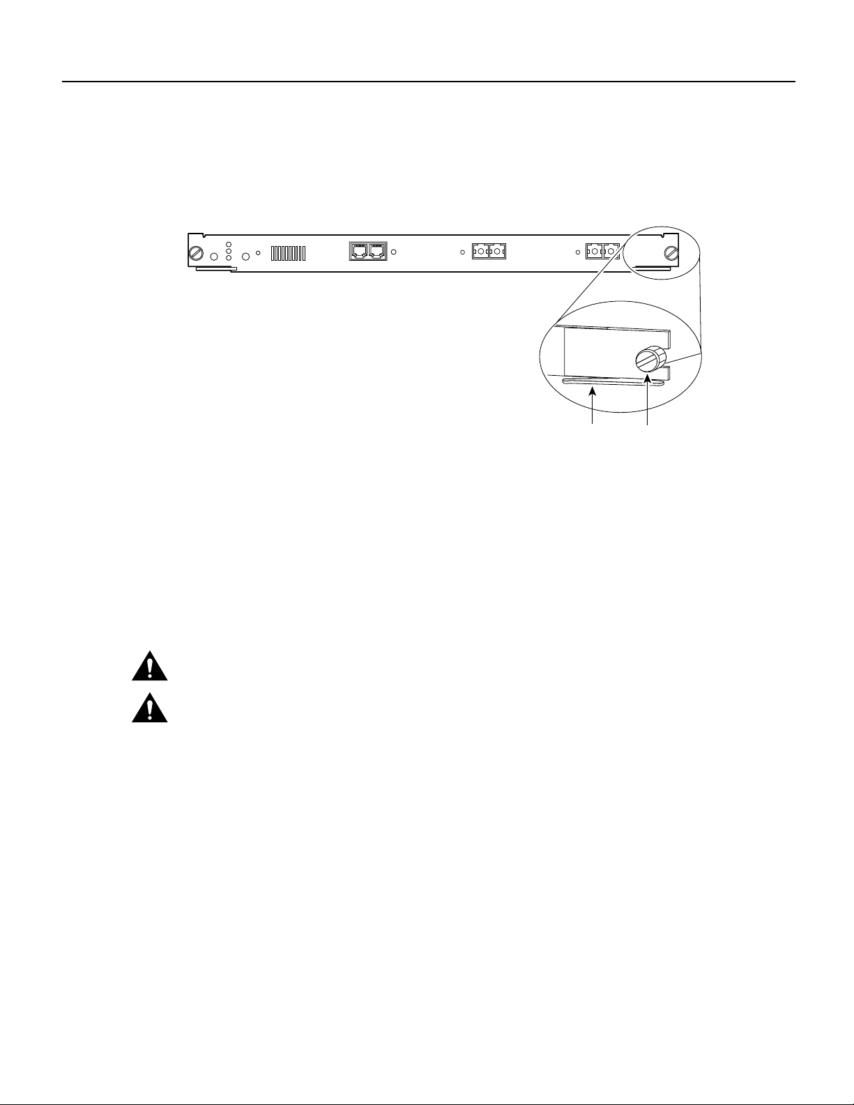
Figure 3 Ejector Levers and Captive Installation Screws
WS-X5550
SYSTEM
STATUS
SUPERVISOR ENGINE III G-SERIES
FAN
PS2
PS1
SWITCH
100%
1%
LOAD
RESET
ACTIVE
CONSOLE
Removing the Supervisor Engine
Before you removea supervisor engine, you shouldfirst upload the current configuration to a server.
This saves time when bringing the supervisor engine back online. Enter the write network
command to upload the configuration file to the network. Enter the copy command to download the
current configuration to a Flash memory device on the new supervisor engine.
To remove the supervisor engine from the switch, follow these steps:
RSFC CONSOLE
CONSOLE
PORT MODE
LINK
PORT 1 PORT 2
LINK
Ejector lever
Captive
installation
screws
24222
Caution To prevent ESD damage, handle switching modules by the carrier edges only.
Caution When removing or inserting a switching module, always wear an ESD wrist strap
connected to the Catalyst 5000 series switch ESD wrist strap connector.
Step 1 Take the necessary precautions to prevent ESD damage, as described in the “Preventing
ESD Damage” section on page 7.
Step 2 If you do not plan to immediately reinstall the supervisor engine you are removing,
disconnect any network interface cables attached to the module ports.
Step 3 Use a screwdriver to loosen the captiveinstallationscrews at theleft and right sides of the
module.
Step 4 Grasp the left and rightejector levers. Simultaneously pull the left lever to the left andthe
right lever to the right to release the module from the backplane connector.
Step 5 Grasp the handleof the modulewith one hand and placeyour other handunder the carrier
to support and guide the module out of the slot. Avoid touching the module itself.
Step 6 Carefully pull the module straight out of the slot, keeping your other hand under the
carrier to guide it. Keep the module at a 90-degree orientation to the backplane.
Step 7 Place the removed supervisor engine on an antistatic mat, foam, or bag.
8 Catalyst 5000 Series Supervisor Engine III G Installation and Configuration Note
Page 9

Step 8 If the slot is to remain empty, install a module filler plate to keep dust out of the chassis
and to maintain proper airflow through the module compartment.
Caution Always install a switching module filler plate in empty switching module slots to maintain the
proper flow of cooling air across the modules.
Note When you removeand replace the supervisor engine, the system provides status messages on
theconsole screen. The messagesarefor information only.Enter the show system and showmodule
commandsto view specific information. Foradditionalinformation, refer to theCatalyst 5000 Series
Software Configuration Guide and the Catalyst 5000 Series Command Reference publication.
Installing the Supervisor Engine
When installing the supervisor engine, note that it must go in a specific slot:
• Catalyst 5000—slot 1
• Catalyst 5505, 5509, and Catalyst 5500—slot 1 (if a second, redundant supervisor is installed, it
goes in slot 2)
Installing the Supervisor Engine
• Catalyst 5002—slot 1
To install the supervisor engine, follow these steps:
Caution To prevent ESD damage, handle switching modules by the carrier edges only.
Caution When removing or inserting a switching module, always wear an ESD wrist strap
connected to the Catalyst 5000 series switch ESD wrist strap connector.
Step 1 Take the necessary precautions to prevent ESD damage, as described in the “Preventing
ESD Damage” section on page 7.
Step 2 To install the supervisor engine, hold the front panel with one hand, and place your other
hand under the carrier to support the supervisor engine. Do not touch the printed circuit
boards or connector pins.
Step 3 Align the edges of the supervisor engine carrier with the slot guides on the sides of the
switch chassis.
Step 4 Pivot the two module ejector levers out away from the faceplate. The ejector levers are
shown pivoted out in Figure 4.
Catalyst 5000 Series Supervisor Engine III G Installation and Configuration Note 9
Page 10
Connecting a Terminal to the Console Port
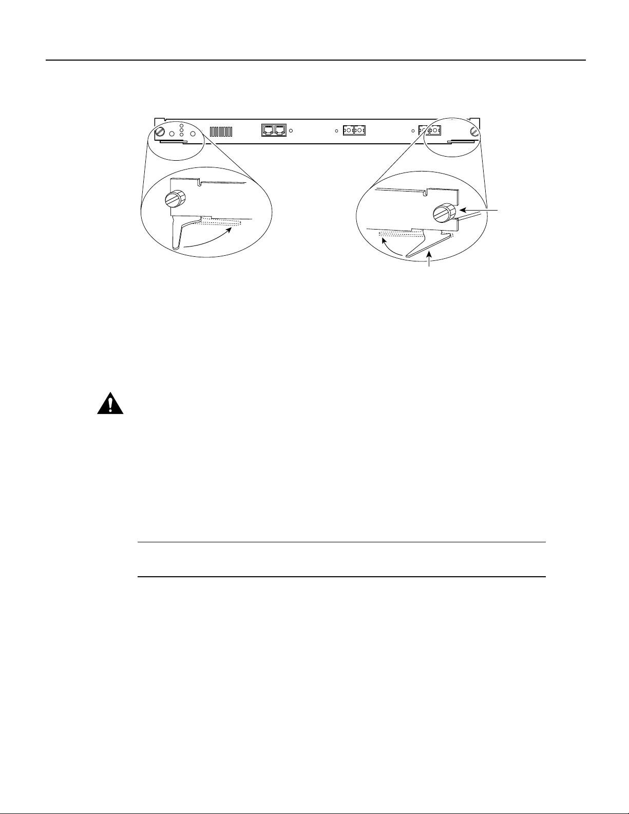
Figure 4 Module Ejector Lever Operation
WS-X5550
FAN
SYSTEM
STATUS
PS2
PS1
SUPERVISOR ENGINE III G-SERIES
SWITCH
100%
1%
LOAD
RESET
ACTIVE
CONSOLE
RSFC CONSOLE
CONSOLE
PORT MODE
LINK
PORT 1 PORT 2
LINK
Captive
installation
screw
Ejector lever
Step 5 Keeping one hand under the carrier to guide the supervisor engine, carefully slide it into
the slot on the Catalyst 5000 series switch until the ejector levers click into place on the
chassis. Be sure to keep the module horizontal to the backplane and avoid touching any
of the components on the module.
Step 6 Using the thumb and forefinger of each hand, simultaneously pivotin both ejector levers,
as shown in Figure 4, to fully seat the switching module in the backplane connector.
Caution Always use the ejector levers when installing or removing switching modules. A module
that is partially seated in the backplane will cause the system to halt and subsequently crash.
24252
Step 7 Use a screwdriver to tighten the captive installation screws at the left and right sides of
the module.
Connecting a Terminal to the Console Port
Connect the terminal using a thin, flat, RJ-45-to-RJ-45 cable (looks like a telephone cable) and an
RJ-45-to-DB-9, RJ-45-to-D-subminiature female, or RJ-45-to-D-subminiature male adapter.
Note An RJ-45-to-RJ-45 cable and adapters are providedin the console port accessory kit shipped
with your Supervisor Engine III.
See the next section, “Configuring a Terminal for Attachment to the Console Port,” for port
configuration details. Table 2 lists the pinouts for the console port.
10 Catalyst 5000 Series Supervisor Engine III G Installation and Configuration Note
Page 11

Configuring a Terminal for Attachment to the Console Port
Table 2 Console Port Pinouts
Console Port Console Device
Pin (signal) Connect to
1 is looped to pin 8
2 (DTR) DSR
3 (RxD) TxD
4 (GND) GND
5 (GND) GND
6 (TxD) RxD
7 (DSR) DTR
8 is looped to pin 1
Table 3 lists the pinouts for the RSFC console port.
Table 3 RSFC Console Port Pinouts
Console Port Console Device
Pin (signal) Connect to
9 is looped to pin 16
10 DTR (out)
11 TxD or RxD
12 (GND)
13 (GND)
14 RxD or TxD
15 RTS (in)
16 is looped to pin 9
Configuring a Terminal for Attachment to the Console Port
Note The console port is an asynchronous serial port; any device connected to this port must be
capable of asynchronous transmission.
Before connecting the console port, check the terminal documentation to determine the baud rate.
The baud rate of the terminal must match the default baud rate (9600 baud) of the console port. Set
up the terminal as follows:
• 9600 baud
• 8 data bits
• No parity
• 1 stop bit
Catalyst 5000 Series Supervisor Engine III G Installation and Configuration Note 11
Page 12
Connecting to the Interface Ports
Connecting to the Interface Ports
The Supervisor Engine III G has two GBICs with 1000BaseSX MMF connectors, 1000BaseLX/LH
MMF and SMF connectors, or 1000BaseZX connectors (see Figure 5).
The 1000BaseSX MMF, 1000Base LX/LH MMF and SMF, and 1000BaseZX ports operate in
full-duplex mode only.
For information on interface cables and equipment, such as Ethernet transceivers, refer to the
Catalyst 5000 Series Supervisor Engine Installation Guide.
1000BaseSX, 1000BaseLX/LH, and 1000BaseZX (Single-Mode or Multimode
Fiber-Optic Connectors)
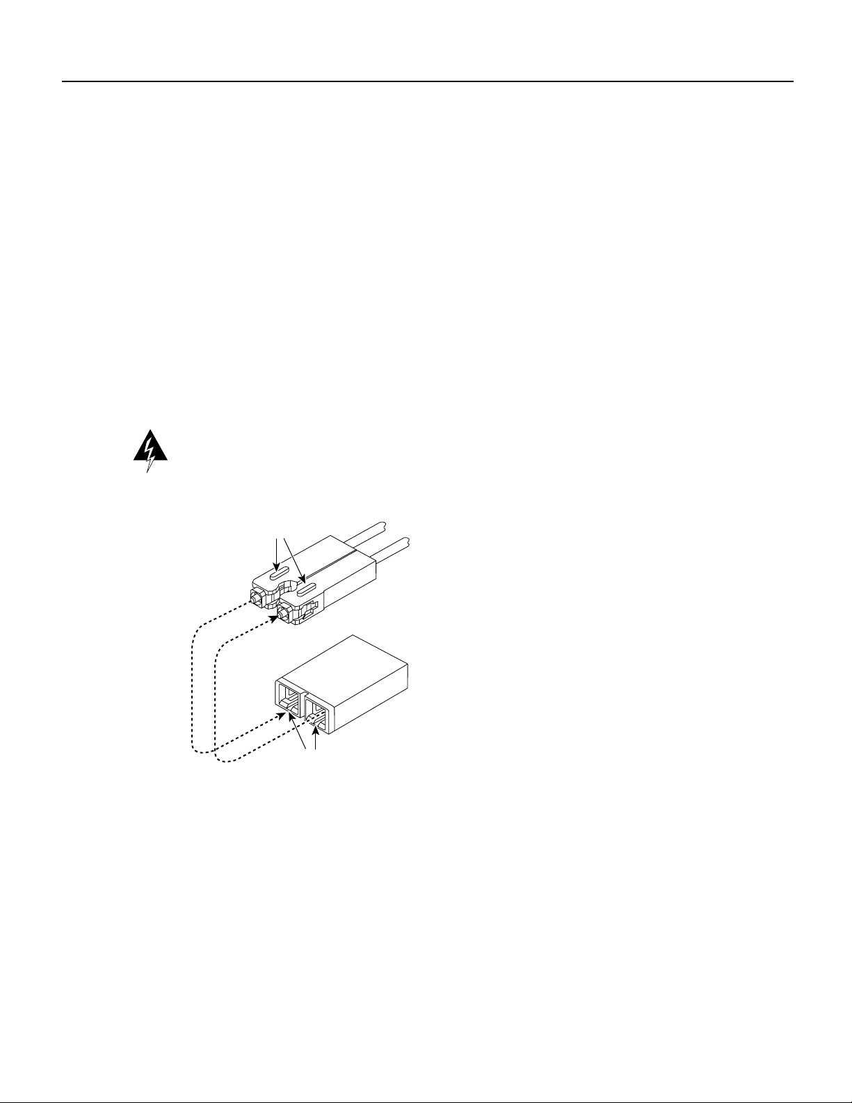
Use SC fiber-optic connectors (see Figure 5) to connect to the 1000BaseSX, 1000BaseLX/LH, and
1000BaseZX ports. Always keep caps and plugs on the fiber-optic connectors on the cable and the
switch when they are not in use.
Warning Because invisible laser radiation may be emitted from the aperture of the port when no
cable is connected, avoid exposure to laser radiation and do not stare into open apertures.
Figure 5 SC Fiber-Optic Connector Type
Keys
Light out
of fiber
Light into
fiber
Plug
Cable
Receptacle
Receiver
Transmitter
Key slots
Connecting Gigabit Ethernet Modules
Supervisor Engine III G has Gigabit Ethernet ports that you can configure with any combination of
GBICs. A GBIC, shown in Figure 6, is a hot-swappable input/output device that plugs into the
module, linking the module with the fiber-optic network. GBIC types are listed in Table 4.
13087
12 Catalyst 5000 Series Supervisor Engine III G Installation and Configuration Note
Page 13
Connecting Gigabit Ethernet Modules
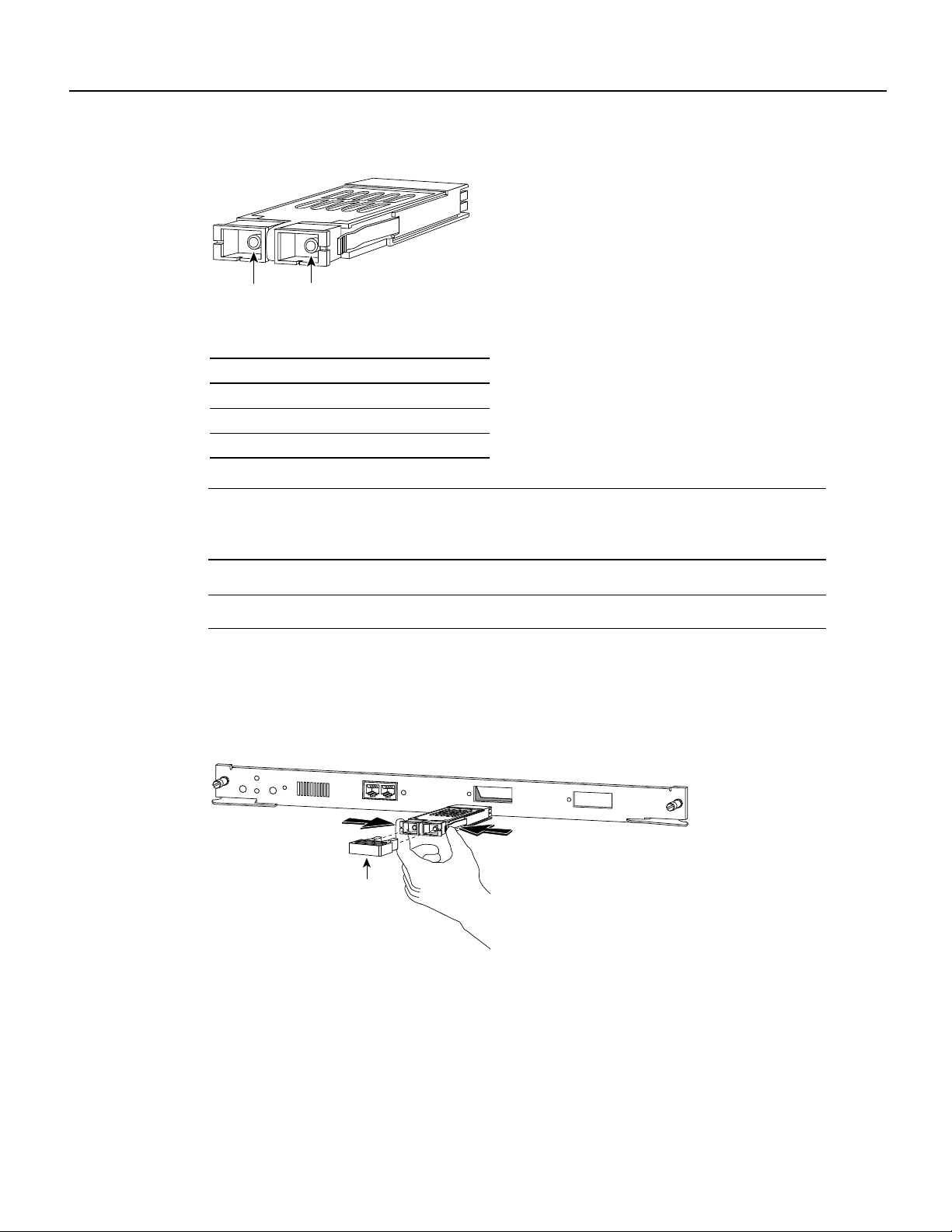
Figure 6 GBIC
11825
Receiver Transmitter
Table 4 GBIC Types
GBIC Product Number
1000BaseSX WS-G5484
1000BaseLX/LH WS-G5486
1000BaseZX WS-G5487
Note Cisco 1000BaseLX/LH interfacesfully comply withthe IEEE 802.3z 1000BaseLX standard.
However, the 1000BaseLX/LH has a higher optical quality, allowing link distances of 10 km over
SMF versus the 5 km specified in the standard.
Note A maximum of 12 1000BaseZX GBICs can be installed in a switch chassis.
The GBIC slides through an opening in the front of the Gigabit Ethernet module and mates with a
connector on the module. (See Figure 7.)
Figure 7 Installing a GBIC (WS-X5403 shown)
WS-X5550
FAN
100%
SYSTEM
STATUS
PS2
PS1
SUPERVISOR ENGINE III G-SERIES
SWITCH
LOAD
1%
RESET
CONSOLE
RSFC CONSOLE
CONSOLE
PORT MODE
LINK
PORT 1
LINK
PORT 2
18357
Plug
Use a SC-type single-mode (fiber) connector, shown in Figure 5, to connect the Gigabit Ethernet
module ports with the external network. Connect the Gigabit Ethernet interface cables to the
appropriate Ethernet network connector.
When using the LX/LH GBIC with 62.5-micron diameter MMF, you must install a
mode-conditioning patch cord (Cisco product number CAB-GELX-625 or equivalent) between the
GBIC and the MMF cable on both the transmit and receive ends of the link. The patch cord is
required for link distances greater than 984 feet (300 m). Refer to the Catalyst 5000 Series
Supervisor Engine Installation Guide for more information on patch cords.
Catalyst 5000 Series Supervisor Engine III G Installation and Configuration Note 13
Page 14

Verifying System Operation
Note The mode-conditioning patch cord is required to comply with IEEE standards. The IEEE
found that link distances could not be met with certain types of fiber-optic cable due to a problem in
the center of some fiber-optic cable cores. The solution is to launch light from the laser at a precise
offset from the center by using the mode-conditioning patch cord. At the output of the patch cord,
the LX/LH GBIC is compliant with IEEE 802.3z standard for 1000BaseLX.
Verifying System Operation
When all interfaces are connected, check all connections, and then follow these steps to verify that
the switch is operational:
Step 1 Check the console terminal and make sure it is on.
Step 2 Verify that the appropriate PS1 and PS2 LEDs on the supervisor engine front panel are
green.
Step 3 While the system initializes, check that the SYSTEM STATUS LED on the supervisor
engine is orange until the boot is complete.
Step 4 Some interface LEDs might go on or blink for a short time. Some LEDs, such as the Link
LED, stay on during the entire boot process. If an interface is already configured, the
LEDs might be on steadily as they detect traffic on the line. Wait until the system boot is
complete before attempting to verify the switching module LED indications.
Note Catalyst 5505, Catalyst 5509, and Catalyst 5500—If you have a redundant
supervisor engine, refer to the Catalyst 5000 Series Installation Guide for a detailed
description of supervisor engine operation in a redundant configuration. By default, the
supervisor engine in slot 1 is the active supervisor; the second supervisor in slot 2 is the
standby supervisor.
Note Many of the switching module LEDs are not on until you configure the interfaces.
Step 5 When the system boot is complete (it takes a few seconds), the supervisor engine begins
to initialize the switching modules.
During this initialization, the LEDs on each switching module behave differently (most
flash on and off). The Status LED on each switching module goes on when initialization
is complete, and the console screen displays a script and system banner.
Note When switching module LEDs are on, this does not necessarily mean that the
interface ports are functional or enabled. Although the LEDs for many interface types go
on at the initial system startup, they do not indicate an accurate status until the interface
is configured. For detailed module-specific LED descriptions, refer to the Catalyst 5000
Series Module Installation Guide.
14 Catalyst 5000 Series Supervisor Engine III G Installation and Configuration Note
Page 15

Note Catalyst 5500 only—The ATM system processor (ASP), ATM port adapter
carrier, and ATM adapter module LEDs are described in the LightStream 1010 ATM
Switch Hardware Installation Guide. The Catalyst 8510 Campus Switch Router (CSR)
Switch Route Processor (SRP) is described in the Catalyst 8510 Campus Switch Router
documentation.These publications are available on the Cisco ConnectionDocumentation
CD and in print.
Note If the system does not complete this verification process, refer to Chapter 6,
“Troubleshooting the Installation,” in the Catalyst 5000 Series Installation Guide for
troubleshooting procedures.
Step 6 Your hardware installation is now complete. Refer to the Software Configuration Guide
and Command Reference publication foryour switch for completesoftware configuration
instructions.
FCC Class A Compliance
This equipment has been tested and found to comply with the limits for a Class A digital device,
pursuant to part 15 of the FCC rules. These limits are designed to provide reasonable protection
against harmful interference when the equipment is operated in a commercial environment. This
equipment generates, uses, and can radiate radio-frequency energy and, if not installed and used in
accordance with the instruction manual, may cause harmful interference to radio communications.
Operation of this equipment in a residential area is likely to cause harmful interference, in which
case users will be required to correct the interference at their own expense.
FCC Class A Compliance
You can determine whether your equipment is causing interference by turning it off. If the
interference stops, it was probably caused by the Cisco equipment or one of its peripheral devices.
If the equipment causes interference to radio or television reception, try to correct the interference
by using one or more of the following measures:
• Turn the television or radio antenna until the interference stops.
• Move the equipment to one side or the other of the television or radio.
• Move the equipment farther away from the television or radio.
• Plug the equipment into an outlet that is on a different circuit from the television or radio. (That
is, make certain the equipment and the television or radio are on circuits controlled by different
circuit breakers or fuses.)
Modifications to this product not authorized by Cisco Systems could void the FCC approval and
negate your authority to operate this product.
Related Documentation
For more detailed installation and configuration information, refer to the following publications:
• Catalyst 5000 Series Installation Guide
• Catalyst 5000 Series Supervisor Engine Installation Guide
• Catalyst 5000 Series Module Installation Guide
Catalyst 5000 Series Supervisor Engine III G Installation and Configuration Note 15
Page 16

Cisco Connection Online
• Software Configuration Guide—Catalyst 5000 Series, Catalyst 4000 Series, Catalyst 2948G
Series, Catalyst 2926G Series
• Command Reference—Catalyst 5000 Series, Catalyst 4000 Series, Catalyst 2948G Series,
Catalyst 2926G Series
• Catalyst 5000 Series Route Switch Feature Card Installation and Configuration Note
Ciscodocumentation and additionalliteratureare availablein a CD-ROMpackage, whichshipswith
your product. The Documentation CD-ROM, a member of the Cisco Connection Family,is updated
monthly. Therefore, it might be more up to date than printed documentation. To order additional
copies of the Documentation CD-ROM, contact your local sales representative or call customer
service. The CD-ROM package is available as a single package or as an annual subscription. You
can also access Cisco documentation on the World Wide Web at http://www.cisco.com,
http://www-china.cisco.com, or http://www-europe.cisco.com.
Cisco Connection Online
CiscoConnection Online (CCO) isCisco Systems’ primary,real-time support channel. Maintenance
customers and partners can self-register on CCO to obtain additional information and services.
Available 24 hours a day, 7 days a week, CCO provides a wealth of standard and value-added
services to Cisco’s customers and business partners. CCO services include product information,
product documentation, software updates, release notes, technical tips, the Bug Navigator,
configuration notes, brochures, descriptions of service offerings, and download access to public and
authorized files.
CCO serves a wide variety of users through two interfaces that are updated and enhanced
simultaneously: a character-based version and a multimedia version that resides on the World Wide
Web (WWW). The character-based CCO supports Zmodem, Kermit, Xmodem, FTP, and Internet
e-mail,and it isexcellentfor quick access toinformation over lowerbandwidths. The WWWversion
of CCO provides richlyformatted documents withphotographs, figures, graphics, and video, as well
as hyperlinks to related information.
You can access CCO in the following ways:
• WWW: http://www.cisco.com
• WWW: http://www-europe.cisco.com
• WWW: http://www-china.cisco.com
• Telnet: cco.cisco.com
• Modem: From North America, 408 526-8070; from Europe, 33 1 64 46 40 82. Use the
following terminal settings: VT100 emulation; databits: 8; parity: none; stop bits: 1; and
connection rates up to 28.8 kbps.
For a copy of CCO’s Frequently Asked Questions (FAQ), contact cco-help@cisco.com. For
additional information, contact cco-team@cisco.com.
Note If you are a network administrator and need personal technical assistance with a Cisco
product that is under warranty or covered by a maintenance contract, contact Cisco’s Technical
Assistance Center (TAC) at 800 553-2447, 408 526-7209, or tac@cisco.com. To obtain general
information about Cisco Systems, Cisco products, or upgrades, contact 800 553-6387,
408 526-7208, or cs-rep@cisco.com.
16 Catalyst 5000 Series Supervisor Engine III G Installation and Configuration Note
Page 17

Documentation CD-ROM
Ciscodocumentation and additionalliteratureare availablein a CD-ROMpackage, whichshipswith
your product. The Documentation CD-ROM, a member of the Cisco Connection Family,is updated
monthly.Therefore, it might bemore current thanprinted documentation. To order additional copies
of the Documentation CD-ROM, contact your local sales representative or call customer service.
The CD-ROM package is available as a single package or as an annual subscription. You can also
access Cisco documentation on the World Wide Web at http://www.cisco.com,
http://www-china.cisco.com, or http://www-europe.cisco.com.
If you are reading Cisco product documentation onthe World Wide Web, you can submit comments
electronically. Click Feedback in the toolbar and select Documentation. After you complete the
form, click Submit to send it to Cisco. We appreciate your comments.
Documentation CD-ROM
This document is to be used in conjunction with the Catalyst 5000 Series Installation Guide and the Catalyst 5000 Series Supervisor Engine Installation Guide.
Access Registrar, AccessPath, Any to Any, AtmDirector, CCDA, CCDE, CCDP, CCIE, CCNA, CCNP, CCSI, CD-PAC, the Cisco logo, Cisco Certified Internetwork Expert logo,
CiscoLink, the Cisco Management Connection logo, the Cisco NetWorks logo, the Cisco Powered Network logo, Cisco Systems Capital, the Cisco Systems Capital logo, Cisco Systems
Networking Academy, the Cisco Technologies logo, ControlStream, FastStep, FireRunner, GigaStack,IGX, JumpStart, KernelProxy, MGX, NaturalNetwork Viewer, NetSonar, Network
Registrar, Packet,PIX, Point and Click Internetworking,Policy Builder, Precept, RouteStream, Secure Script, ServiceWay, SlideCast, SMARTnet, StreamView, The Cell, TrafficDirector,
TransPath, ViewRunner, VirtualStream, VisionWay, VlanDirector, Workgroup Director, and Workgroup Stack are trademarks; Changing the Way We Work, Live, Play, and Learn,
Empowering the Internet Generation, The Internet Economy, and The New Internet Economy are service marks; and Asist, BPX, Catalyst, Cisco, Cisco IOS, the Cisco IOS logo, Cisco
Systems, the Cisco Systems logo, the Cisco Systems Cisco Press logo, Enterprise/Solver, EtherChannel, EtherSwitch, FastHub, FastLink, FastPAD, FastSwitch, IOS, IP/TV, IPX,
LightStream, LightSwitch, MICA, NetRanger, Registrar, StrataView Plus, Stratm, TeleRouter, and VCO are registered trademarks of Cisco Systems, Inc. in the U.S. and certain other
countries. All other trademarks mentioned in this document are the property of their respective owners. (9904R)
Copyright © 1999, Cisco Systems, Inc.
All rights reserved.
Catalyst 5000 Series Supervisor Engine III G Installation and Configuration Note 17
Page 18

Documentation CD-ROM
18 Catalyst 5000 Series Supervisor Engine III G Installation and Configuration Note
 Loading...