

Page 1

Cisco ASR-920-20SZ-M Aggregation Services Router Hardware Installation Guide
First Published: 2018-09-10
Americas Headquarters
Cisco Systems, Inc.
170 West Tasman Drive
San Jose, CA 95134-1706
USA
http://www.cisco.com
Tel: 408 526-4000
800 553-NETS (6387)
Fax: 408 527-0883
Page 2

©
2018 Cisco Systems, Inc. All rights reserved.
Page 3

CONTENTS
CHAPTER 1
CHAPTER 2
Safety Warnings 1
Standard Warning Statements 1
Safety Guidelines for Personal Safety and Equipment Protection 2
Safety Precautions for Module Installation and Removal 3
Safety with Electricity 3
Power Supply Considerations 6
Power Connection Guidelines 6
Guidelines for DC-Powered Systems 7
Guidelines for AC-Powered Systems 7
Prevent Power Loss 7
Preventing ESD Damage 7
Overview 9
Features 9
GigabitEthernet Copper Ports 10
GE SFP Ports 11
SFP+ Ports 11
External Interfaces 11
Network Interfaces 11
Network Timing Interfaces 11
External Alarm Inputs 12
Console 12
Auxiliary Console 12
USB Console 12
USB Memory 12
Online Insertion and Removal 13
Cisco ASR-920-20SZ-M Aggregation Services Router Hardware Installation Guide
iii
Page 4

Contents
Power Supply and Fans 13
Licensing 14
CHAPTER 3
Prepare for Installation 15
Site Planning 15
General Precautions 15
Site Planning Checklist 15
Site Selection Guidelines 16
Airflow for Site Planning 16
Environmental Requirements 16
Physical Characteristics 17
Airflow Guidelines 17
Floor Loading Considerations 18
Site Power Guidelines 18
Electrical Circuit Requirements 19
Site Cabling Guidelines 19
Asynchronous Terminal Connections 19
Interference Considerations 19
Rack-Mounting Guidelines 20
CHAPTER 4
Precautions for Rack-Mounting 20
Rack Selection Guidelines 20
Receive the Device 21
Unpack and Verify Shipped Contents 23
Tools and Equipment 24
Install the Router 25
Rack Compatibility 25
Rack Types 25
Set up Device on Rack or Wall 27
Rack Mount 27
Install Rack Brackets 27
Set up Device on Rack 32
Attaching the Cable Guides 33
Wall Mount 34
Cisco ASR-920-20SZ-M Aggregation Services Router Hardware Installation Guide
iv
Page 5

Install Wall Brackets 34
Wall Mount the Device 35
Ground the Device 36
Connect Power Cables 37
Activate an AC Power Supply 38
Attach Cables to the DC Power Supply 40
Power On the DC Power Supply 41
Connect Gigabit Ethernet Ports 41
Connect SFP Modules 42
Install SFP Modules 42
Remove SFP Modules 43
Connect Fiber Optic SFP Modules 43
Connect RJ-45 Connector 44
Contents
CHAPTER 5
Connect Chassis to Network 44
Connecting Console Cables 44
Connecting to the USB Serial Port Using Microsoft Windows 45
Connecting to the Console Port Using Mac OS X 46
Connecting to the Console Port Using Linux 46
Installing the Cisco USB Device Driver 47
Uninstalling the Cisco USB Device Driver 47
Connecting a USB Flash Device 48
Removing a USB Flash Device 48
Connecting Timing Cables 49
Connecting a Cable to the BITS Interface 49
Connecting Cables to the GPS Interface 49
Connect to EIA Console Port 50
Connect a Management Ethernet Cable 51
Configure the Device 53
Power up the Device 53
Verify the Front Panel LEDs 53
Verify the Hardware Configuration 54
Check Hardware and Software Compatibility 54
Configure Device at Startup 54
Cisco ASR-920-20SZ-M Aggregation Services Router Hardware Installation Guide
v
Page 6

Contents
Access the CLI Using the Console 55
Configure Global Parameters 55
Check the Running Configuration Settings 56
Save the Running Configuration to NVRAM 57
Safely Power Down the Device 57
CHAPTER 6
CHAPTER 7
Replace the Power Supply 59
Remove the DC Power Supply 59
Install the DC Power Supply 60
Remove the AC Power Supply 61
Install the AC Power Supply 62
Troubleshooting Aids 65
Verify Pinout 65
BITS Port Pinouts 65
GPS Port Pinouts 66
Time-of-Day Port Pinouts 66
Alarm Port Pinouts 67
Management Ethernet Port Pinouts 67
USB Console Port Pinouts 68
USB MEM Port Pinouts 68
Check Optical Fiber Specifications 69
Check Alarm Conditions 69
Check LED Indicators 69
PWR and STAT LEDs 70
CPU Management Port LEDs 70
SFP LEDs 71
SFP+ LEDs 71
RJ-45 LEDs 72
Power Supply Unit LEDs 72
System–Interface LED Behavior 72
Cisco ASR-920-20SZ-M Aggregation Services Router Hardware Installation Guide
vi
Page 7

Safety Warnings
This handout topic lists the safety warnings necessary for handling this product. Before you install or service
the chassis, review these safety warnings to avoid injuring yourself or damaging the equipment.
For a complete list of translated safety warnings, see the Regulatory Compliance and Safety Information for
the Cisco ASR 920 Series Aggregation Services Router document.
The safety warnings are grouped under the following sections:
• Standard Warning Statements, on page 1
• Safety Guidelines for Personal Safety and Equipment Protection, on page 2
• Safety Precautions for Module Installation and Removal, on page 3
• Safety with Electricity, on page 3
• Power Supply Considerations, on page 6
• Preventing ESD Damage, on page 7
Standard Warning Statements
CHAPTER 1
Warning
Warning
Warning
To prevent bodily injury when mounting or servicing this unit in a rack, you must take special precautions to
ensure that the system remains stable. The following guidelines are provided to ensure your safety: This unit
should be mounted at the bottom of the rack if it is the only unit in the rack. When mounting this unit in a
partially filled rack, load the rack from the bottom to the top with the heaviest component at the bottom of
the rack. If the rack is provided with stabilizing devices, install the stabilizers before mounting or servicing
the unit in the rack. Statement 1006
This unit is intended for installation in restricted access areas. A restricted access area can be accessed only
through the use of a special tool, lock and key, or other means of security. Statement 1017
Ultimate disposal of this product should be handled according to all national laws and regulations. Statement
1040
Cisco ASR-920-20SZ-M Aggregation Services Router Hardware Installation Guide
1
Page 8
Safety Guidelines for Personal Safety and Equipment Protection
Safety Warnings
Warning
Warning
Warning
Warning
Warning
To prevent the system from overheating, do not operate it in an area that exceeds the maximum recommended
ambient temperature of 158°F (70°C). Statement 1047
The chassis should be mounted on a rack that is permanently affixed to the building. Statement 1049
IMPORTANT SAFETY INSTRUCTIONS: This warning symbol means danger. You are in a situation that
could cause bodily injury. Before you work on any equipment, be aware of the hazards involved with electrical
circuitry and be familiar with standard practices for preventing accidents. Use the statement number provided
at the end of each warning to locate its translation in the translated safety warnings that accompanied this
device. Statement 1071
This is a Class A Device and is registered for EMC requirements for industrial use. The seller or buyer should
be aware of this. If this type was sold or purchased by mistake, it should be replaced with a residential-use
type. Statement 294
This is a class A product. In a domestic environment this product may cause radio interference in which case
the user may be required to take adequate measures. Statement 340
Warning
This equipment is in compliance with the essential requirements and other relevant provisions of Directive
1999/5/EC. Statement 287
Warning
Suitable for mounting on and over a concrete or other non-combustible surface only. Statement 345
SafetyGuidelines for Personal Safetyand Equipment Protection
The following guidelines ensure your safety and protect the equipment. This list does not include all the
potentially hazardous situations. Therefore, you must be alert.
• Before moving the system, always disconnect all power cords and interface cables.
• Never assume that power is disconnected from a circuit; always check.
• Before and after installation, keep the chassis area clean and dust free.
• Keep tools and assembly components away from walk areas where you or others could trip over them.
• Do not work alone if potentially hazardous conditions exist.
Cisco ASR-920-20SZ-M Aggregation Services Router Hardware Installation Guide
2
Page 9
Safety Warnings
Safety Precautions for Module Installation and Removal
• Do not perform any action that creates a potential hazard to people or makes the equipment unsafe.
• Do not wear loose clothing that may get caught in the chassis.
• When working under conditions that may be hazardous to your eyes, wear safety glasses.
Safety Precautions for Module Installation and Removal
Be sure to observe the following safety precautions when you work on the router.
Warning
Warning
Warning
Warning
Class 1 laser product. Statement 1008
Do not stare into the beam or view it directly with optical instruments. Statement 1011
Invisible laser radiation present. Statement 1016
Invisible laser radiation may be emitted from disconnected fibers or connectors. Do not stare into beams or
view directly with optical instruments. Statement 1051
Safety with Electricity
Warning
Before working on a chassis or working near power supplies, unplug the power cord on AC units; disconnect
the power at the circuit breaker on DC units. Statement 12
Warning
Warning
Before working on equipment that is connected to power lines, remove jewelry (including rings, necklaces,
and watches). Metal objects will heat up when connected to power and ground and can cause serious burns
or weld the metal object to the terminals. Statement 43
Avoid using or servicing any equipment that has outdoor connections during an electrical storm.
There may be a risk of electric shock from lightning. Statement 1088
Cisco ASR-920-20SZ-M Aggregation Services Router Hardware Installation Guide
3
Page 10
Safety with Electricity
Safety Warnings
Warning
Warning
Warning
Warning
Warning
Before performing any of the following procedures, ensure that power is removed from the DC circuit.
Statement 1003
Read the installation instructions before connecting the system to the power source. Statement 1004
This product relies on the building’s installation for short-circuit (overcurrent) protection. For a DC installation,
ensure that the branch circuit breaker is rated a maximum 15A for DC systems. For AC systems, 15A for
voltages greater than 200Vac; 20A for voltages below 127Vac. Statement 1005
Take care when connecting units to the supply circuit so that wiring is not overloaded. Statement 1018
The plug-socket combination must be accessible at all times, because it serves as the main disconnecting
device. Statement 1019
Warning
Warning
Warning
Warning
Warning
To avoid electric shock, do not connect safety extra-low voltage (SELV) circuits to telephone-network voltage
(TNV) circuits. LAN ports contain SELV circuits, and WAN ports contain TNV circuits. Some LAN and
WAN ports both use RJ45 connectors. Use caution when connecting cables. Statement 1021
A readily accessible two-poled disconnect device must be incorporated in the fixed wiring. Statement 1022
To reduce the risk of fire, use only 26 AWG or larger telecommunication line cord. Statement 1023
This equipment must be grounded. Never defeat the ground conductor or operate the equipment in the absence
of a suitably installed ground conductor. Contact the appropriate electrical inspection authority or an electrician
if you are uncertain that suitable grounding is available. Statement 1024
Use copper conductors only. Statement 1025
Cisco ASR-920-20SZ-M Aggregation Services Router Hardware Installation Guide
4
Page 11
Safety Warnings
Safety with Electricity
Warning
Warning
Warning
Warning
Warning
This unit might have more than one power supply connection. All connections must be removed to de-energize
the unit. Statement 1028
To prevent personal injury or damage to the chassis, never attempt to lift or tilt the chassis using the handles
on modules (such as power supplies, fans, or cards); these types of handles are not designed to support the
weight of the unit. Statement 1032
Connect the unit only to DC power source that complies with the safety extra-low voltage (SELV) requirements
in IEC 60950 based safety standards. Statement 1033
When installing or replacing the unit, the ground connection must always be made first and disconnected last.
Statement 1046
This equipment must be grounded. Never defeat the ground conductor or operate the equipment in the absence
of a suitably installed ground conductor. Contact the appropriate electrical inspection authority or an electrician
if you are uncertain that suitable grounding is available. Statement 1024
Warning
Warning
Installation of the equipment must comply with local and national electrical codes. Statement 1074
Hazardous voltage or energy may be present on power terminals. Always replace cover when terminals are
not in service. Be sure uninsulated conductors are not accessible when cover is in place. Statement 1086
When working on equipment that is powered by electricity, follow these guidelines:
• Locate the room’s emergency power-off switch. If an electrical accident occurs, you know where to
quickly turn off the power.
• Before starting work on the system, turn off the DC main circuit breaker and disconnect the power
terminal block cable.
• Disconnect all power when:
• Working on or near power supplies
• Installing or removing a device chassis or network processor module
• Performing most hardware upgrades
• Never install equipment that appears damaged.
Cisco ASR-920-20SZ-M Aggregation Services Router Hardware Installation Guide
5
Page 12

Power Supply Considerations
Use the following guidelines when working with any equipment that is disconnected from a power source,
but connected to telephone wiring or network cabling:
Safety Warnings
• Carefully examine your work area for possible hazards, such as moist floors, ungrounded power extension
cables, and missing safety grounds.
• Never assume that power is disconnected from a circuit; always check.
• Never perform any action that creates a potential hazard to people or makes the equipment unsafe.
• If an electrical accident occurs and you are uninjured:
• Use caution to avoid injuring yourself.
• Turn off power to the device.
• If possible, send another person to get medical aid. Otherwise, determine the condition of the victim,
and then call for help.
• Determine whether the person needs rescue pulsing or external cardiac compressions; then take
appropriate action.
• When installing or modifying telephone lines, use caution.
• Never install telephone jacks in wet locations unless the jack is designed to handle such locations.
• Never install telephone wiring during a lightning storm.
Power Supply Considerations
Check the power at your site to ensure that you are receiving clean power (free of spikes and noise). If
necessary, install a power conditioner.
Power Connection Guidelines
This section provides guidelines for connecting the device power supplies to the site power source.
Warning
Warning
This equipment is intended to be grounded to comply with emission and immunity requirements. Ensure that
the switch functional ground lug is connected to earth ground during normal use. Statement 1064
The plug-socket combination must be accessible at all times, because it serves as the main disconnecting
device. Statement 1019
6
Warning
This product requires short-circuit (overcurrent) protection, to be provided as part of the building installation.
Install only in accordance with national and local wiring regulations. Statement 1045
Cisco ASR-920-20SZ-M Aggregation Services Router Hardware Installation Guide
Page 13

Safety Warnings
Guidelines for DC-Powered Systems
Basic guidelines for DC-powered systems include the following:
• Each chassis power supply should have its own dedicated input power source. The source must comply
with the safety extra-low voltage (SELV) requirements in the UL 60950, CSA 60950, EN 60950, and
IEC 60950 standards.
• The circuit must be protected by a dedicated two-pole circuit breaker. The circuit breaker should be sized
according to the power supply input rating and local or national code requirements.
• The circuit breaker is considered the disconnect device and should be easily accessible.
• The system ground is the power supply and chassis ground.
• Do not connect the DC return wire to the system frame or to the system-grounding equipment.
• Use the grounding lug to attach a wrist strap for ESD protection during servicing.
Guidelines for AC-Powered Systems
Basic guidelines for AC-powered systems include the following:
• Each chassis power supply should have its own dedicated branch circuit.
• The circuit breaker should be sized according to the power supply input rating and local or national code
requirements.
• The AC power receptacles used to plug in the chassis must be the grounding type. The grounding
conductors that connect to the receptacles should connect to protective earth ground at the service
equipment.
Guidelines for DC-Powered Systems
Prevent Power Loss
Use the following guidelines to prevent power loss to the router:
• To prevent loss of input power, ensure that the total maximum load on each circuit supplying the power
supplies is within the current ratings of the wiring and breakers.
• In some systems, you can use an UPS to protect against power failures at your site. Avoid UPS types
that use ferroresonant technology. These UPS types can become unstable with systems such as the Cisco
ASR 920 Series Router, which can have substantial current-draw fluctuations due to bursty data traffic
patterns.
Determining power requirements is useful for planning the power distribution system needed to support the
router.
Preventing ESD Damage
Warning
This equipment needs to be grounded. Use a green and yellow 6 AWG ground wire to connect the host to
earth ground during normal use. Statement 383
Electrostatic discharge (ESD) can damage equipment and impair electrical circuitry. ESD may occur when
electronic printed circuit cards are improperly handled and can cause complete or intermittent failures. When
removing and replacing modules, always follow ESD prevention procedures:
• Ensure that the router chassis is electrically connected to earth ground.
Cisco ASR-920-20SZ-M Aggregation Services Router Hardware Installation Guide
7
Page 14

Preventing ESD Damage
Safety Warnings
• Wear an ESD-preventive wrist strap, ensuring that it makes good skin contact. To channel unwanted
ESD voltages safely to ground, connect the clip to an unpainted surface of the chassis frame. To guard
against ESD damage and shocks, the wrist strap and cord must operate effectively.
• If no wrist strap is available, ground yourself by touching a metal part of the chassis.
• When installing a component, use any available ejector levers or captive installation screws to properly
seat the bus connectors in the backplane or midplane. These devices prevent accidental removal, provide
proper grounding for the system, and help to ensure that bus connectors are properly seated.
• When removing a component, use available ejector levers or captive installation screws, if any, to release
the bus connectors from the backplane or midplane.
• Handle components by their handles or edges only; do not touch the printed circuit boards or connectors.
• Place a removed component board side up on an antistatic surface or in a static-shielding container. If
you plan to return the component to the factory, immediately place it in a static-shielding container.
• Avoid contact between the printed circuit boards and clothing. The wrist strap only protects components
from ESD voltages on the body; ESD voltages on clothing can still cause damage.
• Never attempt to remove the printed circuit board from the metal carrier.
Note
For the safety of your equipment, periodically check the resistance value of the antistatic wrist strap. It should
be between 1 and 10 Mohm.
Cisco ASR-920-20SZ-M Aggregation Services Router Hardware Installation Guide
8
Page 15

Features
CHAPTER 2
Overview
The Cisco ASR-920-20SZ-M Router is a fixed configuration router that enables Service Providers to provide
business, residential, and mobile access services to their users. It is the Carrier Ethernet access platform
providing Ethernet services.
• Features, on page 9
• GigabitEthernet Copper Ports, on page 10
• GE SFP Ports, on page 11
• SFP+ Ports, on page 11
• External Interfaces, on page 11
• Power Supply and Fans, on page 13
• Licensing, on page 14
The Cisco ASR 920 Series Router family includes:
• Cisco ASR 920 [ASR-920-20SZ-M]—This sub-family with 1 RU form factor has fixed ENET interfaces
(four 10GE and twenty-four 1GE) and redundant modular power supplies (AC/DC).
Cisco ASR-920-20SZ-M Aggregation Services Router Hardware Installation Guide
9
Page 16
GigabitEthernet Copper Ports
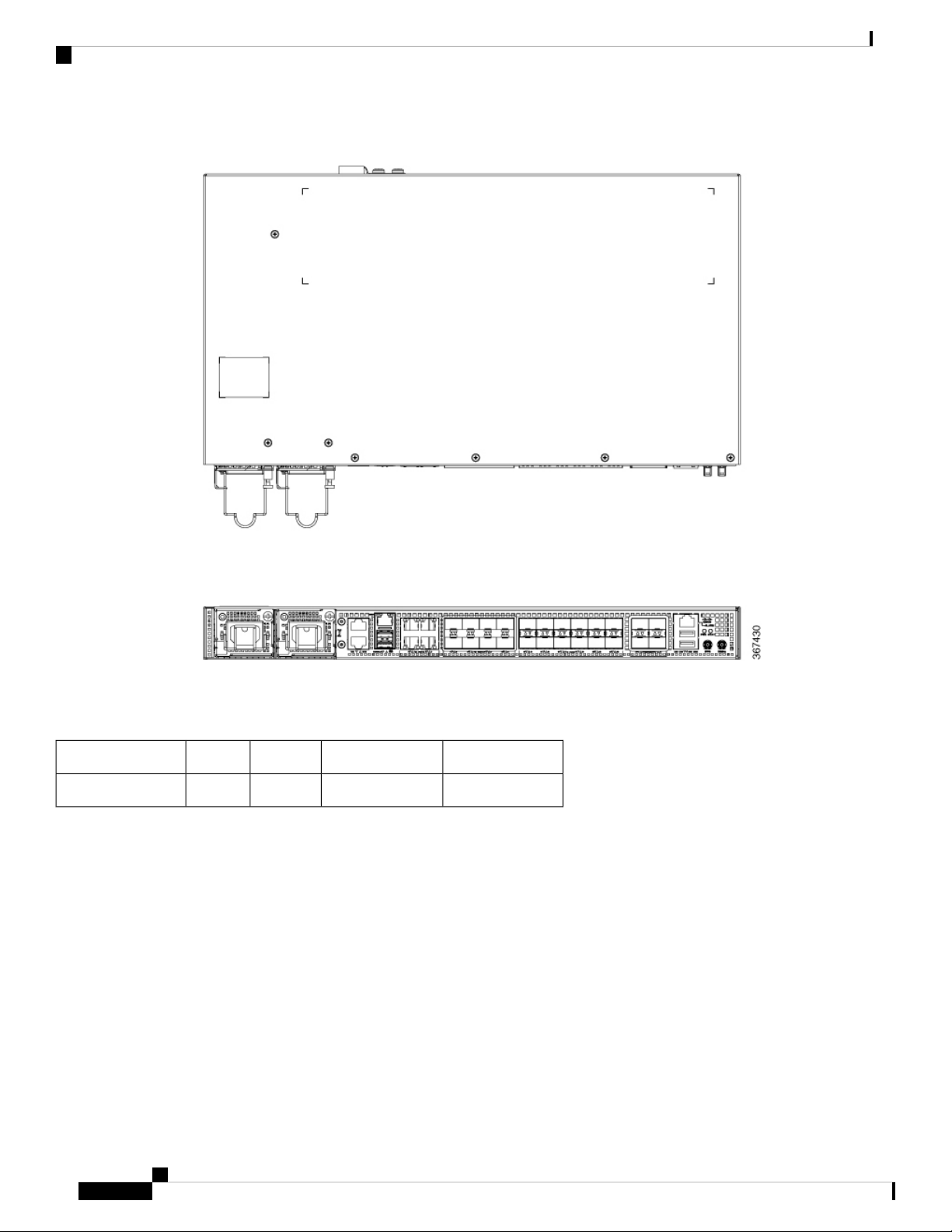
Figure 1: Cisco ASR-920-20SZ-M Top and Front Panel
Overview
The following table provides a snapshot of the number and type of supported ports:
Table 1: Supported Ports on Cisco ASR-920-20SZ-M Router
GigabitEthernet Copper Ports
Fixed copper GigabitEthernet (GE) interfaces are provided through standard RJ-45 connectors. These ports
support the following features:
• Standard 10/100/1000Base-T/TX operation with forced or auto-negotiation for speed and duplex.
• Automatic crossover (auto-MDIX) for straight-through and crossover connections.
• Pause flow control as defined by the 802.3x standard.
• Frame size of 9216 bytes.
• Synchronous ENET operation that provides its recovered receive clock as an input clock source for the
SETS as well as uses the system-wide reference clock to derive its transmit clock.
Type of 10 GE PortType of 1 GE Port10 GE Port1 GE PortASR 920 Sub-family
4 SFP+20 Fiber 4 Copper424ASR-920-20SZ-M
Cisco ASR-920-20SZ-M Aggregation Services Router Hardware Installation Guide
10
Page 17

Overview
GE SFP Ports
The GE SFP ports support the following features:
Note
Copper based SFPs do not support synchronous ENET operations.
GE SFP Ports
• 100Base-FX and 1000Base-X SFP modules.
• Copper SFP modules
• Digital optical monitoring as specified by the SFP.
• Any mix of SFPs is supported unless specifically noted.
• Pause flow control as defined by the 802.3x standard.
• Frame size of 9216 bytes.
• Synchronous ENET operation that provides its recovered receive clock as an input clock source for the
SETS as well as uses the system-wide reference clock to derive its transmit clock.
SFP+ Ports
The SFP+ ports support the following features:
• Digital optical monitoring as specified by the optical transceiver module.
• Any mix of SFPs is supported unless specifically noted.
• Pause flow control as defined by the 802.3x standard.
• Frame size of 9216 bytes.
External Interfaces
The Cisco ASR 920-20SZ-M Router has these external physical interfaces on the front panel:
Network Interfaces
The network interfaces are provided through fixed ports.
• GE SFP ports—supports 100/1000 modes
• GE copper ports—supports 10/100/1000 operation
• 10GE SFP+—supports 10G mode
Network Timing Interfaces
• BITS input or output—The BITS interfaces support clock recovery from either a T1 at 1.544 MHz or an
E1 at 2.048 MHz, configurable by software. BITS interface is provided through a standard RJ-48 connector
on the front panel.
Cisco ASR-920-20SZ-M Aggregation Services Router Hardware Installation Guide
11
Page 18

External Alarm Inputs
• 1PPS input or output and ToD input or output—This shielded RJ-45 interface is used for input or output
of time-of-day (ToD) and 1PPS pulses. ToD format includes both NTP and IEEE 1588-2008 time formats.
The same RS422 pins for 1PPS and TOD are shared between input and output directions. The direction for
each can be independently configurable through software.
Use an SMB connector on the front panel for the following:
• GPS 10 Mhz input and output—10 MHz input for GPS Synchronization.
• GPS 1 PPS input and output—1 PPS input for GPS Synchronization.
External Alarm Inputs
The router supports four dry contact alarm inputs through an RJ-45 jack on the front panel.
• Normally Open—indicates that no current flows through the alarm circuit and the alarm is generated
when the current is flowing.
Each alarm input can be provisioned as critical, major, or minor.
Overview
Console
The RS232 console port provides transmission (Tx), reception (Rx), and ground (Gnd).
Auxiliary Console
The Auxiliary Console port provides transmission (Tx), reception (Rx), and ground (Gnd).
USB Console
A single USB 2.0 Type-A receptacle on the front panel of the router provides console access to ROMMON,
Cisco IOS-XR and diagnostics. While it uses the Type-A connector, it operates as a USB peripheral only for
connection to an external host computer. This interface requires the use of a Type-A to Type-A connector
instead of a standard USB cable.
Note
Use of the USB console is mutually exclusive of the RS232 console port. This interface requires the use of a
Type-A to Type-A USB cable.
USB Memory
A single USB 2.0 Type-A receptacle on the front panel of the router allows external USB mass storage devices,
such as standard USB flash drives. This interface is used to load images, load or store configurations, write
logs, and so on.
Cisco ASR-920-20SZ-M Aggregation Services Router Hardware Installation Guide
12
Page 19

Overview
Note
More than 8 GB is not supported in ROMMON mode.
Online Insertion and Removal
The router supports the following OIR operations:
• When an SFP is removed, there is no effect on traffic flowing on other ports.
• When an SFP is installed, the system initializes that port for operation that is based on the current
configuration. If the inserted SFP is incompatible with the current configuration for that port, the port
does not become operational until the configuration is updated.
• Both power supplies are installed and active, the load may be shared between them or a single PSU could
support the whole load. When a power supply is not working or the input cable is removed, the remaining
power supply takes the entire load without disruption.
Online Insertion and Removal
Power Supply and Fans
The Cisco ASR-920-20SZ-M Router supports a 1+1 redundant configuration with the combination of an AC
and a DC, or two AC, or two DC power supplies. One AC and one DC power supply in the same router is
also a supported configuration. The PSUs are hot-swappable. Load is shared between PSUs when both the
PSUs are inserted and powered-up. Status LED provided on both AC and DC PSU indicates the status and
output condition.
Note
DC PSU can be switched on or off using a switch on the front panel of the DC PSU.
Note
This product requires surge protection as part of the building installation. To comply with the Telcordia
GR-1089 NEBS standard for electromagnetic compatibility and safety, an external surge protective device
(SPD) is required at the AC power service equipment.
Note
For DC systems, if a surge of more than 1KV is expected, add an appropriate external surge protective device.
The Cisco ASR-920-20SZ-M Router has six fixed fans as a part of the system. The system is designed to
operate at its maximum operating temperature of 70ºC and at an altitude of 300 meters. If a single fan fails,
the system runs at a maximum operating temperature of 65ºC. The fan is not removable and therefore, during
a failure, the system must be replaced.
Note
In case of fan failure, we recommend that you get a qualified technician to replace the faulty device within
96 hours.
Cisco ASR-920-20SZ-M Aggregation Services Router Hardware Installation Guide
13
Page 20

Licensing
Licensing
Overview
The Cisco ASR-920-20SZ-M Router support the following types of licenses:
• Port Licensing—Port Upgrade license is available as a "Pay as you Grow" model.
• 1G upgrade license
• 10G upgrade license
• Bulk licensing—Bulk port licensing allows you to enable all the ports with a single license.
• Timing license (1588)—Timing license is required if the router is used as a master clock.
• Advanced Metro IP Access
• Metro IP Access
• Metro Access (default)
The following methods are used to activate the above licenses:
• Cisco Software Licensing—The Cisco Software License Activation feature is a set of processes and
components to activate Cisco software feature sets by obtaining and validating fee-based Cisco software
licenses.
Note
Licenses generated by the Cisco Software Licensing are tied to the UDI of the chassis and a corresponding
watchtower device certificate (WDC) is stored in the system.
• Cisco Smart Licensing—Smart Licensing is usage-based licensing where devices register with the Cisco
Secure server.
Cisco ASR-920-20SZ-M Aggregation Services Router Hardware Installation Guide
14
Page 21

Prepare for Installation
Before you install the router, you must prepare your site for the installation.
Preparing your site involves these tasks:
• Site Planning, on page 15
• Receive the Device, on page 21
Site Planning
The sections describe how to plan for the installation of the Cisco ASR 920 Series Router.
General Precautions
Observe the following general precautions when using and working with your Cisco ASR 920 Router:
• Keep your system components away from radiators and heat sources and do not block cooling vents.
• Do not spill food or liquids on your system components and never operate the product in a wet
environment.
• Do not push any objects into the openings of your system components. Doing so can cause fire or electric
shock by shorting out interior components.
• Position system cables and power supply cable carefully. Route system cables and the power supply
cable and plug so that they are not stepped on or tripped over. Be sure that nothing else rests on your
system component cables or power cable.
• Do not modify power cables or plugs. Consult a licensed electrician or your power company for site
modifications. Always follow your local and national wiring rules.
• If you turn off your system, wait at least 30 seconds before turning it on again to avoid damage of system
components.
CHAPTER 3
Site Planning Checklist
Use the following checklist to carry out all site planning tasks:
• The site meets environmental requirements.
• The site’s air conditioning system can compensate for the heat dissipation of the chassis.
• The floor space that the chassis occupies can support the weight of the system.
Cisco ASR-920-20SZ-M Aggregation Services Router Hardware Installation Guide
15
Page 22
Site Selection Guidelines
• Electrical service to the site complies with the safety with electricity requirements.
• The electrical circuit servicing the chassis complies with the power supply requirements.
• Console port wiring and cabling limitations have been considered in accordance to TIA/EIA-232F.
• The chassis Ethernet cabling distances are within prescribed limits.
• The equipment rack where the chassis is to be installed complies with prescribed requirements.
• When selecting rack location, safety, ease of maintenance, and proper airflow requirements have been
considered.
Site Selection Guidelines
The device requires specific environmental operating conditions. Temperature, humidity, altitude, and vibration
can affect the performance and reliability of the device.
The device is designed to meet the industry EMC, safety, and environmental standards.
Prepare for Installation
Airflow for Site Planning
Table 2: Cisco ASR-920-20SZ-M Airflow
ASR-920-20SZ-M
Environmental Requirements
Environmental monitoring of the chassis protects the system and components from damage due to excessive
voltage and temperature conditions. To ensure normal operation and avoid unnecessary maintenance, plan
and prepare your site configuration before installation. After installation, ensure that the environmental
characteristics continue to be met.
For an outside plant installation (cell site cabinet, hut, and so on), you require to protect the chassis against
airborne contaminants, dust, moisture, insects, pests, corrosive gases, polluted air, or other reactive elements.
We recommend that you install the unit in a fully sealed enclosure or cabinet. Examples of such cabinets
include IP65 cabinets with heat exchanger complying with Telcordia GR487. Temperature must be maintained
within –40ºC to 70ºC.
Place the device inside a space that is protected from direct weather and environmental stresses by an enclosure.
FeatureDevice
power supply
Maximum System Airflow
(CFM) at Maximum System
Temperature
93.020GE SFP, 4Cu and 4-10GE: Modular
Ensure the operating climate as defined by Class 2 of GR-3108-CORE for premium variants.
• –40°C (-40°F) and 70°C (158°F)
• 5 and 85% RH
Ensure the operating climate as defined by Class 1 of GR-3108-CORE for base variants.
• –5°C (23°F) and 50°C (122°F)
Cisco ASR-920-20SZ-M Aggregation Services Router Hardware Installation Guide
16
Page 23

Prepare for Installation
• < 15 to 85% RH
Physical Characteristics
To set the device at its proper location, be familiar with its physical characteristics.
Airflow Guidelines
Cool air is circulated through the chassis by fans that are located along the back of the device.
The internal fans maintain acceptable operating temperatures for the internal components by drawing in cool
air through the vents and circulating that air through the chassis.
The direction of airflow is from front-to-back.
To ensure adequate airflow through the equipment rack, we recommend that you always maintain a minimum
clearance distance as mentioned in the following specifications.
• Front clearance—5 inches (12.7 centimeters)
• Rear clearance—3.93 inches (10 centimeters)
Physical Characteristics
Note the following points:
• When installing chassis in a back-to-back position with another device, ensure a minimum of 3.93 inches
(10 centimeters) airflow clearance between them. Also, ensure that the device behind the chassis is not
installed in a way that it blows air into the chassis.
• An over-temperature condition may occur within the rack, if airflow through the rack and the device is
restricted, or if the air that is drawn into the rack is warm.
• Ensure that the site is dust free. Dust tends to clog the device fans, reducing the flow of cooling air
through the equipment rack and the devices that occupy it, thus increasing the risk of an over-temperature
condition.
• Enclosed racks must have adequate ventilation. Because each device generates heat, ensure that the racks
are not congested. An enclosed rack must have louvered sides and a fan to provide cool air. Heat that is
generated by the equipment near the bottom of the rack may be drawn upward into the intake ports of
the equipment above.
• When mounting a chassis on an open rack, ensure that the rack frame does not block the exhaust fans.
• When a rack-installed equipment fails, especially equipment on an enclosed rack, if possible try operating
the equipment by itself. Power off all other equipment on the rack (and in adjacent racks) to give the
device maximum cooling air and clean power.
• Avoid installing the chassis in a location in which the chassis air intake vents may draw in the exhaust
air from an adjacent equipment. Consider how the air flows through the device; the airflow direction is
from front to back, with ambient air drawn in from the vents located on the sides of the chassis.
Caution
When mounting the device on any type of rack equipment, ensure that the temperature of inlet air to the device
does not exceed the specified operating temperature limits of the product.
Cisco ASR-920-20SZ-M Aggregation Services Router Hardware Installation Guide
17
Page 24
Airflow Guidelines for ETSI Rack Installation
Airflow Guidelines for ETSI Rack Installation
When you install a device on a 2 or 4-post rack, the front and rear doors of the cabinet must be removed. We
recommended that you always maintain a minimum clearance distance as mentioned the following.
• Front clearance—5 inches (12.7 centimeters)
• Rear clearance—3.93 inches (10 centimeters)
To mount the chassis in a 4-post enclosed cabinet, ensure a minimum of 3.93 inches (10 centimeters) of
clearance on each side of the chassis.
Floor Loading Considerations
Ensure that the floor under the rack supporting the chassis is able to support the combined weight of the rack
and all the other installed equipment.
For additional information about floor loading requirements, see the GR-63-CORE, Network Equipment
Building System (NEBS) Requirements: Physical Protection document.
Prepare for Installation
Site Power Guidelines
The chassis has specific power and electrical wiring requirements. Adhering to these requirements ensures
reliable operation of the system. Follow these precautions and recommendations when planning your site
power for the chassis:
• The redundant power option provides a second, identical power supply to ensure uninterrupted power
supply.
• Connect each power supply to a separate input power source. Otherwise, it results in total power failure
to the system due to a fault in the external wiring or a tripped circuit breaker.
• To prevent loss of input power, ensure that the maximum load on each circuit is within the current ratings
of the wiring and the breakers.
• Check the power at your site before installation, and periodically after installation, to ensure that you are
receiving clean power. If necessary, install a power conditioner.
• Provide proper grounding to avoid personal injury and damage to the equipment due to power surges or
lightning striking power lines. The chassis ground must be attached to a central office or other interior
ground system.
Caution
This product requires short-circuit (overcurrent) protection to be provided as part of the building installation.
Install only in accordance with national and local wiring regulations.
Note
The chassis installation must comply with all the applicable codes, and is approved for use with only copper
conductors. The ground bond-fastening hardware must be compatible and preclude loosening, deterioration,
and electrochemical corrosion of hardware and joined material. Attachment of the chassis ground to a central
office or other interior ground system must be made with a 6-AWG gauge wire copper ground conductor.
Cisco ASR-920-20SZ-M Aggregation Services Router Hardware Installation Guide
18
Page 25

Prepare for Installation
Electrical Circuit Requirements
Each chassis requires a dedicated electrical circuit. If you equip the device with dual-power feeds, provide a
separate circuit for each power supply to avoid compromising the power redundancy feature.
The chassis supports both DC source or an AC source. Ensure that equipment grounding is present and observe
power-strip ratings. Make sure that the total ampere rating of all the products plugged into the power strip
does not exceed 80% of the rating.
Site Cabling Guidelines
This section contains guidelines for wiring and cabling at your site. When preparing your site for network
connections to the chassis, consider the type of cable that is required for each component and cable limitations.
Consider the distance limitations for signaling, electromagnetic interference (EMI), and connector compatibility.
Possible cable types are fiber, thick or thin coaxial, foil twisted-pair, or unshielded twisted-pair cabling.
Also, consider any additional interface equipment that you need, such as transceivers, hubs, switches, modems,
channel service units (CSU), or data service units (DSU).
Before you install the chassis, have on hand all additional external equipment and cables. For information
about ordering, contact a Cisco customer service representative.
Electrical Circuit Requirements
The extent of your network and the distances between the network interface connections depend, in part, on
the following factors:
• Signal type
• Signal speed
• Transmission medium
The distance and rate limits that are referenced in the following sections are the IEEE-recommended maximum
speeds and distances for signaling purposes. Use this information as a guideline when planning your network
connections before installing the chassis.
If wires exceed the recommended distances, or if wires pass between buildings, give special consideration to
the possibility of a lightning strike in your vicinity. The electromagnetic pulse due to lightning or other
high-energy phenomena can easily couple enough energy into unshielded conductors to destroy electronic
devices. If you have had problems of this sort in the past, you may want to consult experts in electrical surge
suppression and shielding.
Asynchronous Terminal Connections
The chassis provides a console port to connect a terminal or computer for local console access. The port has
an RJ-45 connector and supports RS-232 asynchronous data with distance recommendations that are specified
in the IEEE RS-232 standard.
Interference Considerations
When wires are run for any significant distance, there is a risk of receiving stray signals on the wires as
interference. If interference signals are strong, it results in data errors or equipment damage.
The following sections describe the sources of interference and how to minimize their effects on the chassis.
Cisco ASR-920-20SZ-M Aggregation Services Router Hardware Installation Guide
19
Page 26

Electromagnetic Interference
Electromagnetic Interference
All the equipment that is powered by AC current can propagate electrical energy that can cause EMI and
possibly affect the operation of other equipment. The typical sources of EMI are equipment power cords and
power service cables from electric utilities.
Strong EMI can destroy the signal drivers and receivers in the chassis. It can even create an electrical hazard
by causing power surges through the power lines into installed equipment. These problems are rare, but could
be catastrophic.
To resolve these problems, you need specialized knowledge and equipment that could consume substantial
time and money. However, you can ensure that you have a properly grounded and shielded electrical
environment, paying special attention to the need for electrical surge suppression.
Radio Frequency Interference
When electromagnetic fields act over a long distance, radio frequency interference (RFI) may be propagated.
Building wiring can often act as an antenna, receiving the RFI signals and creating more EMI on the wiring.
If you use a twisted-pair cable in your plant wiring with a good distribution of grounding conductors, the plant
wiring is unlikely to emit radio interference. If you exceed the recommended distances, use a high-quality
twisted-pair cable with one ground conductor for each data signal.
Prepare for Installation
Lightning and AC Power Fault Interference
If signal wires exceed the recommended cabling distances, or if signal wires pass between buildings, you may
encounter a lightning strike on the chassis.
The electromagnetic pulse (EMP) generated by lightning or other high-energy phenomena can couple enough
energy into unshielded conductors and damage or destroy electronic equipment. For such problems, you must
consult with RFI and EMI experts to ensure adequate electrical surge suppression and shielding of signal
cables in your operating environment.
Rack-Mounting Guidelines
The following sections provide guidelines for selecting racks and precautions for mounting the chassis on a
rack:
Precautions for Rack-Mounting
Follow these rack-mount guidelines to ensure your safety:
• Ensure that the rack is level and stable before extending a component from the rack.
• Ensure that proper airflow is provided to the components on the rack.
• Do not step on or stand on any component or system when servicing other systems or components on a
rack.
• If the rack is provided with stabilizing devices, install the stabilizers before mounting or servicing the
chassis.
Rack Selection Guidelines
Ensure the 2 or 4-post, 19 inches (48.3 centimeters) or 23 inches (58.42 centimeters) rack that you select
complies with the Electronic Industries Association (EIA) standard for equipment racks (EIA-310-D). The
rack must have at least two posts with mounting flanges to mount the chassis.
Cisco ASR-920-20SZ-M Aggregation Services Router Hardware Installation Guide
20
Page 27

Prepare for Installation
Receive the Device
Caution
When mounting a chassis in any type of rack equipment, ensure that the temperature of the inlet air to the
chassis does not exceed the specified operating temperature of the chassis.
The distance between the center lines of the mounting holes on the two mounting posts must be 18.31 inches
(46.50 centimeters) ± 0.06 inch (± 0.15 centimeter). The rack-mounting hardware included with the chassis
is suitable for most 19 inches (48.3 centimeters) equipment racks.
Install the chassis on a rack with the following features:
• NEBS-compliant, 19 inches (48.3 centimeters) rack or 23 inches (58.42 centimeters).
• EIA or European Telecommunications Standards Institute (ETSI) hole patterns in the mounting rails.
The required mounting hardware is shipped with the chassis. If the rack on which you plan to install the
chassis has metric-threaded rails, you must provide your own metric-mounting hardware.
• Perforated top and open bottom for ventilation to prevent overheating.
• Leveling feet for stability.
Do not install the device on an enclosed rack because the chassis requires an unobstructed flow of cooling air
to maintain the acceptable operating temperature. If you use an enclosed rack, ensure that the airflow
requirements are maintained as discussed in the Airflow Guidelines section.
Receive the Device
Each device is shipped in a container that is strapped to a pallet.
Cisco ASR-920-20SZ-M Aggregation Services Router Hardware Installation Guide
21
Page 28

Receive the Device
Prepare for Installation
Figure 2: The Router Packaged for Shipping
DescriptionLabelDescriptionLabel
1
Packing carton4Outside carton for
accessories
2
Accessories tray5Assembly packaging
material
——Router3
Cisco ASR-920-20SZ-M Aggregation Services Router Hardware Installation Guide
22
Page 29

Prepare for Installation
Unpack and Verify Shipped Contents
Procedure
Step 1 Inspect the shipping container for any shipping damage. If there is obvious physical damage, contact your
Cisco service representative, else continue with the remaining steps.
Step 2 Unpack the device.
Step 3 Inspect the device.
Step 4 Use the following table to verify the contents of the container. Do not discard the shipping container. You
will need the container in the future if you move or ship the device.
What to do next
Table 3: Default Shipping Container Contents
Unpack and Verify Shipped Contents
Optional equipment
Note
Note
DescriptionComponent
Cisco ASR-920-20SZ-MDevice
One disposable wrist strap (optional)ESD, wrist strap (disposable)
Cisco ASR 920 Series Router Pointer CardDocumentation
Check the container for the following optional equipment:
• Power cord if an AC power supply is shipped.
• Lugs if a DC power supply is shipped.
Note
If you do not specify the type of power cable, US power cable for the AC device variant
is supplied.
Most Cisco documentation is available online. The chassis Pointer Card that is shipped with your Cisco ASR
920 Series Router contains links and information to other online documentation.
If the product is not in use, store the device in the initial packaged condition or in an ESD PE sealed bag with
silica gel.
Cisco ASR-920-20SZ-M Aggregation Services Router Hardware Installation Guide
23
Page 30

Tools and Equipment
Prepare for Installation
Table 4: Accessories Kit
AccessoriesPIDCategoryVariant
YesA920-RCKMT-1919 inchesASR-920-20SZ-M
YesA920-RCKMT-23-H23 inches
YesA920-RCKMT-ETSIETSI
YesA920-RCKMT-19Wall mount
NoNADesktop
Tools and Equipment
You need the following tools and equipment to install and upgrade the device and its components:
• ESD-preventive cord and wrist strap
• Antistatic mat or antistatic foam
• Number 1 and Number 2 Phillips-head screwdrivers
• #12-24 pan-head screws to secure the device to the equipment rack.
• Cables for connecting to network ports (based on the configuration)
• Ethernet hub, switch, or PC with a network interface card for connecting to the Ethernet ports
• Console terminal that is configured for 9600 baud, 8 data bits, no parity, no flow control, and 1 stop bit.
• Console cable for connecting to the console port
• Ratcheting torque screwdriver with a Phillips head that exerts up to 30-pound force per square inch
(0.02-kilograms force per square millimeter (kgf/mm2)) of pressure.
• Crimping tool as specified by the ground lug manufacturer
• Wire-stripping tools for stripping both 6 and 14-AWG wires
• Tape measure and level
• Ratcheting torque screwdriver with a Phillips head that exerts up to 15 inch-pounds (1.69 newton meters)
of torque for attaching the ground wire to the device.
Cable bracket
YesA920-CBL-GUIDE
A920-CBL-BRKT-E
(ETSI)
YesA920-DRIP-TRAYDip Tray
Cisco ASR-920-20SZ-M Aggregation Services Router Hardware Installation Guide
24
Page 31

Install the Router
Before you begin this task, ensure that you have read and understood the safety warnings in the Standard
Warning Statements section of the Safety Warnings handout topic.
Installing the Cisco ASR-920-20SZ-M Router involves these tasks:
• Rack Compatibility, on page 25
• Set up Device on Rack or Wall, on page 27
• Ground the Device, on page 36
• Connect Power Cables, on page 37
• Connect Gigabit Ethernet Ports, on page 41
• Connect Chassis to Network, on page 44
Rack Compatibility
We recommend that you follow these rack specifications.
CHAPTER 4
Rack Types
Figure 3: Rack specification EIA (19 inches and 23 inches)
Cisco ASR-920-20SZ-M Aggregation Services Router Hardware Installation Guide
25
Page 32

Rack Types
Install the Router
Table 5: Rack specification EIA (19 inches and 23 inches)
4 Post
2 Post
4 Post
2 Post
Figure 4: Four Post Rack Type
Rack TypePost Type
centimeters)
centimeters)
Rack Front Opening
(X)
Rack Mounting Hole
Centre-Centre (Y)
Mounting Flange
Dimension (Z)
482.6mm (19”)465mm (18.312”)450.8mm (17.75”)19 inches (48.3
584.2mm (23”)566.7mm (22.312”)552.45mm (21.75”)23 inches (58.4
Cisco ASR-920-20SZ-M Aggregation Services Router Hardware Installation Guide
26
Page 33

Install the Router
Set up Device on Rack or Wall
Figure 5: Two Post Rack Type
Set up Device on Rack or Wall
You can choose to either set up the Cisco ASR 920 Router on a rack or wall mount it.
Rack Mount
You can choose to either set up the router in a horizontal or a vertical mounting position on the rack.
Install Rack Brackets
The device is shipped with rack mounting brackets that are to be secured on the sides of the device.
Procedure
Step 1 Remove the rack mounting brackets from the accessory kit and position them beside the device.
Note
You can install the brackets at any of the 3 positions that are shown in the figure.
Cisco ASR-920-20SZ-M Aggregation Services Router Hardware Installation Guide
27
Page 34

Install Rack Brackets
Install the Router
Figure 6: Attaching Mounting Brackets to Router for a 19-inch EIA Rack (Front Position)
Figure 7: Attaching Mounting Brackets to Router for a 19-inch EIA Rack (Middle Position)
Cisco ASR-920-20SZ-M Aggregation Services Router Hardware Installation Guide
28
Page 35

Install the Router
Install Rack Brackets
Figure 8: Attaching Mounting Brackets to Router for a 19-inch EIA Rack (Rear Position)
Figure 9: Attaching Mounting Brackets to Router for a 23-inch EIA Rack (Front Position)
Cisco ASR-920-20SZ-M Aggregation Services Router Hardware Installation Guide
29
Page 36

Install Rack Brackets
Install the Router
Figure 10: Attaching Mounting Brackets to Router for a 23-inch EIA Rack (Middle Position)
Figure 11: Attaching Mounting Brackets to Router for a 23-inch EIA Rack (Rear Position)
Cisco ASR-920-20SZ-M Aggregation Services Router Hardware Installation Guide
30
Page 37

Install the Router
Install Rack Brackets
Figure 12: Attaching Mounting Brackets to Router for a ETSI Rack (Front Position)
Figure 13: Attaching Mounting Brackets to Router for a ETSI Rack (Middle Position)
Cisco ASR-920-20SZ-M Aggregation Services Router Hardware Installation Guide
31
Page 38

Set up Device on Rack
Install the Router
Figure 14: Attaching Mounting Brackets to Router for a ETSI Rack (Rear Position)
Step 2 Secure the bracket to the device with the recommended maximum torque of 10 inch-pounds (1.1 newton
meters).
Set up Device on Rack
Note
Ensure adequate clearance when mounting the device on a rack.
Note
Install cable guides before installing the device in a 19 inches (48.3 centimeters) EIA rack.
Procedure
Step 1 Position the device on the rack, and use the images as a guide to set up the device.
Cisco ASR-920-20SZ-M Aggregation Services Router Hardware Installation Guide
32
Page 39

Install the Router
Attaching the Cable Guides
Figure 15: Set up Device on Rack
Step 2 Use a tape measure and level to verify that the device is installed straight and on level.
Attaching the Cable Guides
Note
If the chassis is mounted using 19-inch brackets, you must assemble the cable guides before installing the
chassis on the rack.
Procedure
Step 1 Position the cable A920-CBL-GUIDE (left and right) against the front of the chassis and align the two screw
holes, as shown in the figure.
Cisco ASR-920-20SZ-M Aggregation Services Router Hardware Installation Guide
33
Page 40

Wall Mount
Install the Router
Figure 16: Attach Cable Guides
Step 2 Secure the cable guides with the two M6x12mm screws supplied with the cable kit. The recommended
maximum torque is 26 inch-pounds (3 newton meters).
Wall Mount
Install the wall mounting brackets and cable guides on to the chassis before you mount the chassis on the wall.
Install Wall Brackets
The device is shipped with wall mounting brackets that are to be secured on the sides of the device.
Procedure
Step 1 Remove the wall mounting brackets from the accessory kit and position them beside the device.
Note
You can install the brackets as shown in the figure.
Cisco ASR-920-20SZ-M Aggregation Services Router Hardware Installation Guide
34
Page 41

Install the Router
Wall Mount the Device
Figure 17: Wall Mount Bracket
Step 2 Secure the bracket to the device with the recommended maximum torque of 10 inch-pounds (1.1 newton
meters).
Wall Mount the Device
Note
Install cable guides before mounting the device on the wall.
Procedure
Step 1 Position the cable guide against the front of the device, and align the four screw holes as shown in the figure.
Step 2 Use a tape measure and level to verify that the device is installed straight and on level.
Step 3 Secure the cable guides with four M6x12mm screws that are supplied with the cable kit. The recommended
maximum torque is 26 inch-pounds (3 newton meters).
Cisco ASR-920-20SZ-M Aggregation Services Router Hardware Installation Guide
35
Page 42

Ground the Device
Step 4 Position the device vertically on the wall.
Figure 18: Mounting the Router on the Wall
Install the Router
Caution
Before mounting the device, ensure that all unused holes at the sides of the device are protected
with screws.
Ground the Device
Before you begin this task, ensure that you have read and understood the safety warnings in the Preventing
ESD Damage section of the Safety Warnings handout topic.
Before you connect the power or turn on the power to the device, you must provide an adequate device ground
(earth) connection to your device.
This section describes how to ground the device. The grounding lug location is on the back panel of the device.
Cisco ASR-920-20SZ-M Aggregation Services Router Hardware Installation Guide
36
Page 43

Install the Router
Tip
Ensure that the grounding lug wire does not cover the fan opening.
Figure 19: Attach a Ground Lug to the Rear of the Device
Connect Power Cables
Caution
To prevent personal injury or damage to the chassis, before making connections to the device, ensure that you
disconnect the power at the circuit breaker.
Verify your carrier’s requirements for grounding. This unit must be installed in a restrictive access location
and must be permanently grounded to a minimum 6-AWG copper ground wire.
Procedure
Step 1 If your ground wire is insulated, use a wire-stripping tool to strip the ground wire to 0.5 inch (12.7 millimeters)
± 0.02 inch (± 0.5 millimeters).
Figure 20: Stripping a Ground Wire
Step 2 Slide the open end of the 2-hole ground lug over the exposed area of the ground wire.
Step 3 Using a crimping tool (the one specified by the ground lug manufacturer), crimp the ground lug to the ground
wire.
Step 4 Use a Phillips head screwdriver to attach the 2-hole ground lug and wire assembly to the device with the 2
pan-head Phillips head screws.
Step 5 Connect the other end of the ground wire to a suitable grounding point at your site.
Connect Power Cables
Before you begin this task, ensure that you have read and understood the safety warnings in the Safety with
Electricity section of the Safety Warnings handout topic.
The Cisco ASR-920-20SZ-M Router supports both AC and DC power supplies. Based on your device power
supply, attach the AC and the DC power cables.
Cisco ASR-920-20SZ-M Aggregation Services Router Hardware Installation Guide
37
Page 44

Activate an AC Power Supply
Activate an AC Power Supply
Follow these steps to activate an AC power supply:
Procedure
Step 1 Attach the AC power retainer cord as shown in the figure below.
Figure 21: Attaching the AC Power Retainer Cord
Install the Router
Step 2 Lift the power retainer and plug in the AC power supply.
Step 3 Push the retainer cord towards the power supply cord to lock it in place as shown in the figure below.
Cisco ASR-920-20SZ-M Aggregation Services Router Hardware Installation Guide
38
Page 45

Install the Router
Activate an AC Power Supply
Figure 22: Locking the Power Retainer Cord
Step 4 Connect the other end of the power cord to an AC-input power source.
Step 5 Verify power supply operation by checking that the power supply LED is green.
Step 6 If the LEDs indicate a power problem, see LED Indicators section for troubleshooting information.
Step 7 If you are installing a redundant power supply, repeat these steps for the second power source.
Note
If you are installing a redundant AC power supply, ensure that each power supply is connected to
a separate power source in order to prevent power loss in the event of a power failure.
Cisco ASR-920-20SZ-M Aggregation Services Router Hardware Installation Guide
39
Page 46

Attach Cables to the DC Power Supply
Attach Cables to the DC Power Supply
Note
When installing DC power supply, use 14 AWG, 90°C wires. Always ensure that the building’s installation
for short-circuit (overcurrent) protection does not exceed 15A.
To attach the DC power supplies:
Procedure
Step 1 Open the DC power supply guard.
Step 2 Attach the DC supply wires in the designated screws. See the figure below.
Figure 23: Connecting the DC Power Supply Wires
Install the Router
Step 3 Close the DC power supply guard.
Cisco ASR-920-20SZ-M Aggregation Services Router Hardware Installation Guide
40
Page 47

Install the Router
Power On the DC Power Supply
After the router is either rack mounted or mounted on the wall, perform these tasks to complete the installation:
Procedure
Step 1 Power on the DC power supply. See the figure below.
Figure 24: Powering on the DC Power Supply
Power On the DC Power Supply
power on/off switch1
Step 2 Connect the front-panel ports.
Connect Gigabit Ethernet Ports
Gigabit Ethernet (GE) ports can be connected to other devices using either fiber optic or copper cables. The
choice depends on whether the communication distance between your devices is long or short.
If you choose fiber optic cables, connect suitable Small Form-factor Pluggable (SFP) modules. The device
supports various SFP and SFP+ modules, including optical and Ethernet modules. For information on how
to install and remove SFP and SFP+ modules, see the documentation for the SFP or SFP+ module at: Cisco
SFP and SFP+ Transceiver Module Installation Notes. Select the port on the device where you insert the SFP
module.
If you choose copper cables, connect to an RJ-45 connector.
The device 10/100/1000 ports configure themselves to operate at the speed of devices to which they are
connected. By default, autonegotiation is enabled in the chassis. You can manually set the speed and the
duplex parameters. If the device to which the ports are connected does not autonegotiate, low performance
or no linkage may result.
To maximize performance, choose one of these methods for configuring the GE ports:
• Have ports autonegotiate both speed and duplex parameters.
• Set speed and duplex parameters on both ends of the connection.
Cisco ASR-920-20SZ-M Aggregation Services Router Hardware Installation Guide
41
Page 48

Connect SFP Modules
Use the mdix auto command in the interface configuration mode to enable an automatic media-dependent
interface with crossover detection. After you enable the automatic media-dependent interface, the device
detects the required cable type for copper Ethernet connections and configures the interface accordingly. Then,
use either a crossover or a straight-through cable for connecting to a copper 10/100/1000 port. If the mdix
auto command fails to enable the interface, connect the cable through SFP modules.
Connect SFP Modules
Before you begin this task, ensure that you have read and understood the safety warnings in the Safety
Precautions for Module Installation and Removal section of the Safety Warnings handout topic.
Use only Cisco SFP modules on a Cisco device. Each SFP module has an internal serial EEPROM that is
encoded with security information. This encoding provides a way for Cisco to identify and validate that the
SFP modules meet the requirements of the device.
Install the Router
Caution
We recommend that you wait for 30 seconds between the removal and insertion of an SFP module from the
device. The wait period allows the transceiver software to initialize and synchronize with the device. Changing
an SFP before this wait period could result in transceiver initialization issues that disable the SFP.
This section provides procedures for installing and connecting SFP modules. Also, it provides the procedure
for removing SFP modules.
Install SFP Modules
Caution
We strongly recommend that you do not install (or remove) an SFP module with its cables connected because
of the potential damage that may be caused to the cables, the cable connector, or the optical interfaces in the
SFP modules. Disconnect all cables before removing or installing an SFP module.
Removing and installing an SFP module can shorten its useful life. Do not remove and insert SFP modules
unless necessary.
The following figure shows an SFP module that has a bale-clasp latch.
Figure 25: SFP Module with Bale-Clasp Latch
Some SFP modules identify the top side of the module with send (TX) and receive (RX) has markings or
arrows that show the direction of the connection. If the SFP module that you are using has such markings,
use them to identify the top of the module.
Cisco ASR-920-20SZ-M Aggregation Services Router Hardware Installation Guide
42
Page 49

Install the Router
Step 1 Attach an ESD-preventive wrist strap to your wrist and to a bare metal surface on the chassis.
Step 2 Align the SFP module at the front of the slot opening.
Step 3 Insert the SFP module into the slot until the connector on the module snaps into place at the rear of the slot.
Remove SFP Modules
Procedure
Caution
Step 4 Insert the appropriate cable connector into the SFP module:
• For fiber-optic SFP modules, insert the LC cable.
• For copper 1000BASE-T SFP modules, insert the RJ-45 cable.
Remove SFP Modules
Follow these steps to remove an SFP module when it is necessary.
Procedure
Step 1 Attach an ESD-preventive wrist strap to your wrist and to a bare metal surface on the chassis.
Step 2 Disconnect the cable from the SFP module, and insert a dust plug into the cable end.
Step 3 Unlock and remove the SFP module.
If the module has a bale-clasp latch, pull the bale down and out to eject the module. If the bale-clasp latch is
obstructed, use a small, flat-blade screwdriver or any other narrow instrument to open the bale-clasp latch.
Do not remove the dust plugs from the fiber-optic SFP module port or the rubber caps from the
fiber-optic cable until you are ready to connect the cable. The plugs and caps protect the SFP module
ports and cables from contamination and ambient light. Store the dust plugs for later use.
Step 4 Grasp the SFP module between your thumb and index finger, and carefully remove it from the module slot.
Step 5 For fiber-optic SFP modules, insert a dust plug into the optical ports of the SFP module to keep the optical
interfaces clean.
Step 6 Place the removed SFP module in an antistatic bag or other protective environment.
For information about inspecting and cleaning fiber-optic connections, see: Inspection and Cleaning Procedures
for Fiber-Optic Connections.
Connect Fiber Optic SFP Modules
Caution
Do not remove the rubber plugs from the SFP module port or from the fiber optic cable until you are ready
to connect the cable. The plugs and caps protect the SFP module ports and cables from contamination and
ambient light.
Cisco ASR-920-20SZ-M Aggregation Services Router Hardware Installation Guide
43
Page 50

Connect RJ-45 Connector
Procedure
Step 1 Remove the rubber plugs from the module port and fiber optic cable, and store them for future use.
Step 2 Insert one end of the fiber optic cable into the SFP module port.
Step 3 Insert the other end into a fiber optic connector at a target device.
Step 4 Observe the port's LED status.
The LED turns green when the device and the target device establish a link.
If the LED is off, check whether the target device is turned on, or whether there is any failure in the target
device.
Step 5 If necessary, reconfigure and restart the device or target device.
Connect RJ-45 Connector
Install the Router
Procedure
Step 1 To connect to workstations, servers, and devices, connect a straight-through cable to an RJ-45 connector at
the front panel.
When connecting to devices or repeaters, use a crossover cable.
Step 2 Connect the other end of the cable to an RJ-45 connector at the other device. The port's LED turns on when
both the device and the connected device have established a link.
If the port LED does not turn on, check whether the device at the other end is turned on or whether there is
any failure.
Note
Step 3 Reconfigure and reboot the connected device if necessary.
Step 4 Repeat Steps 1 to 3 for each device that is to be connected.
On user network interface (UNI) ports, the port LED turns green after the link is established.
Connect Chassis to Network
Note
Connect only SELV services to all the device ports.
Connecting Console Cables
This section describes how to connect to the Cisco ASR 920 Router using console cables:
Cisco ASR-920-20SZ-M Aggregation Services Router Hardware Installation Guide
44
Page 51

Install the Router
Connecting to the USB Serial Port Using Microsoft Windows
Connecting to the USB Serial Port Using Microsoft Windows
This procedure shows how to connect to the USB serial port using Microsoft Windows.
Note
Install the USB device driver before establishing a physical connection between the router and the PC, by
plugging the USB console cable into the USB serial port. Otherwise, the connection fails. For more information,
see the Installing the Cisco USB Device Driver section.
Procedure
Step 1 Connect a USB Type A-to-Type A cable to the USB console port, as shown in figure. If you are using the
USB serial port for the first time on a Windows-based PC, install the USB driver now according to the
instructions in the following sections:
• Installing the Cisco USB Device Driver
• Uninstalling the Cisco USB Device Driver
Note
You cannot use the USB port and the EIA port concurrently. When the USB port is used, it takes
priority over the EIA port.
Step 2 Connect the USB Type A cable to the PC.
Step 3 To communicate with the router, start a terminal emulator application, such as Microsoft Windows
HyperTerminal. Configure the software with the following parameters:
• 9600 baud
• 8 data bits
• no parity
• 1 stop-bit
• no flow control
Figure 26: Connecting the USB Console Cable to the Cisco ASR 920 Router
Cisco ASR-920-20SZ-M Aggregation Services Router Hardware Installation Guide
45
Page 52

Connecting to the Console Port Using Mac OS X
Install the Router
CableLabelCableLabel
Connecting to the Console Port Using Mac OS X
This procedure describes how to connect a Mac OS X system USB port to the console using the built-in OS
X terminal utility.
Procedure
Step 1 Use the Finder to choose Applications > Utilities > Terminal.
Step 2 Connect the OS X USB port to the router.
Step 3 Enter the following commands to find the OS X USB port number:
Example:
macbook:user$ cd /dev
macbook:user$ ls -ltr /dev/*usb*
crw-rw-rw- 1 root wheel 19, 6 Dec 9 16:25 /dev/tty.usbmodem1411
crw-rw-rw- 1 root wheel 19, 7 Dec 9 16:25 /dev/cu.usbmodem1411DT-macbook:dev user$
2USB Type-A console port1
USB USB Type-A
to USB Type-A
console cable
Step 4 Connect to the USB port with the following command followed by the router USB port speed:
Example:
macbook:user$ screen /dev/tty.usbmodem1411 9600
To disconnect the OS X USB console from the terminal window, enter Ctrl-a followed by Ctrl-\
Connecting to the Console Port Using Linux
This procedure shows how to connect a Linux system USB port to the console using the built-in Linux terminal
utility.
Procedure
Step 1 Open the Linux terminal window.
Step 2 Connect the Linux USB port to the router.
Step 3 Enter the following commands to find the Linux USB port number:
Example:
root@usb-suse# cd /dev
root@usb-suse /dev# ls -ltr *ACM*
Cisco ASR-920-20SZ-M Aggregation Services Router Hardware Installation Guide
46
Page 53

Install the Router
crw-r--r-- 1 root root 188, 0 Jan 14 18:02 ttyACM0
root@usb-suse /dev#
Step 4 Connect to the USB port with the following command, followed by the router USB port speed:
Example:
root@usb-suse /dev# screen /dev/ttyACM0 9600
To disconnect the Linux USB console from the terminal window, enter Ctrl-a followed by : then quit
Installing the Cisco USB Device Driver
A USB device driver must be installed the first time a Microsoft Windows-based PC is connected to the USB
serial port on the router.
This procedure describes how to install the Microsoft Windows USB device driver in Microsoft Windows
XP / Windows Vista / Windows 2000 / Windows 7 / Windows 8. Download the driver for your router model
from the Tools and Resources Download Software site, USB Console Software category.
Installing the Cisco USB Device Driver
Note
To Download the driver, you must have a valid service contract associated to your Cisco.com profile.
Procedure
Step 1 Unzip the file asr-9xx_usbconsole_drivers.zip.
Step 2 Double-click xrusbser_ver2100_installer.exe in the XR21x141x-Win-DriversOnly-Vers2.1.0.0/EXE folder.
Installation Wizard GUI is displayed.
Step 3 Click Next. The InstallShield Wizard Completed window is displayed.
Step 4 Click Finish.
Step 5 Connect the USB cable to the PC and router USB console ports. Follow the on-screen instructions to complete
the installation of the driver.
Step 6 XR21V1401 USB UART Device driver successfully installed message is displayed.
The USB console is ready for use.
Uninstalling the Cisco USB Device Driver
This procedure describes how to uninstall the Microsoft Windows USB device driver in Microsoft Windows
XP / Windows Vista / Windows 2000 / Windows 7 / Windows 8.
Note
Disconnect the router console terminal before uninstalling the driver.
Cisco ASR-920-20SZ-M Aggregation Services Router Hardware Installation Guide
47
Page 54

Connecting a USB Flash Device
Procedure
Step 1 Choose Start > Control Panel > Add or Remove Programs (Uninstall a program).
Step 2 Scroll to Windows Driver Package - Exar corporation (xrusbser) Ports and click Remove. The Program
Maintenance window is displayed.
Step 3 Click Yes to uninstall the driver.
Connecting a USB Flash Device
To connect a USB flash device to the Cisco ASR 920 Router, insert the memory stick in the USB port labeled
USB MEM. The flash memory module can be inserted only one way, and can be inserted or removed regardless
of whether the router is powered up or not.
The following figure shows the USB port connector on the Cisco ASR 920 Router.
Figure 27: Cisco ASR 920 Router Flash Token Memory Stick
Install the Router
Removing a USB Flash Device
To remove and replace a USB flash token memory stick from and into a Cisco ASR 920 Router, follow these
steps:
Procedure
Step 1 Execute the eject usb0: command before removing the USB from the router.
Example:
rommon 2 > eject usb0
rommon 2 >
If you do not run this command before removing the USB, the following error message is displayed:
rommon 2 > dir usb0:
usb_stor_BBB_comdat:usb_bulk_msg error
failed to send CBW status 34
RESET:stall
usb_stor_BBB_comdat:usb_bulk_msg error
failed to send CBW status 34
RESET:stall
usb_stor_BBB_comdat:usb_bulk_msg error
Step 2 Pull the memory stick from the USB port.
Cisco ASR-920-20SZ-M Aggregation Services Router Hardware Installation Guide
48
Page 55

Install the Router
Step 3 To replace the Cisco USB flash memory stick, simply insert the module into the USB port labeled USB MEM,
as shown in figure. The flash memory module can be inserted only one way, and can be inserted or removed
regardless of whether the router is powered up or not.
This completes the USB flash memory installation procedure.
Connecting Timing Cables
The sections describe how to connect timing cables to the Cisco ASR 920 Router:
Connecting Timing Cables
Warning
To comply with the Telcordia GR-1089 NEBS standard for electromagnetic compatibility and safety, connect
the ToD ports only to intra-building or unexposed wiring or cable. The intrabuilding cable must be shielded
and the shield must be grounded at both ends. The intra-building port(s) of the equipment or subassembly
must not be metallically connected to interfaces that connect to the OSP or its wiring. These interfaces are
designed for use as intra-building interfaces only (Type 2 or Type 4 ports as described in GR-1089-CORE)
and require isolation from the exposed OSP cabling. The addition of Primary Protectors is not sufficient
protection in order to connect these interfaces metallically to OSP wiring.
Connecting a Cable to the BITS Interface
The following steps describe how to connect a cable to the router’s BITS port:
Procedure
Step 1 Confirm that the router is powered off.
Step 2 Connect one end of the cable to the BITS port using a straight-through, shielded RJ48C-to-RJ48C cable.
Step 3 Connect the other end to the BTS patch or demarcation panel at your site.
Step 4 Turn on the power to the router.
For information about the BITS port pinouts, see the Troubleshooting section.
Connecting Cables to the GPS Interface
The sections describe how to connect cables from the Cisco ASR 920 Router to a GPS unit for input or output
timing of frequency:
Note
When installing the cables to the RSP, we recommend that you leave a service loop of extra cable to enable
fan tray removal.
Cisco ASR-920-20SZ-M Aggregation Services Router Hardware Installation Guide
49
Page 56

Connecting a Cable to the Input 10-Mhz or 1-PPS Interface
Connecting a Cable to the Input 10-Mhz or 1-PPS Interface
Procedure
Step 1 Connect one end of a shielded mini-coax cable to the GPS unit.
Step 2 Connect the other end of the shielded mini-coax cable to the 10-Mhz or 1-PPS port on the RSP of the Cisco
ASR 920 Router.
Connecting a Cable to the Output 10-Mhz or 1-PPS Interface
Procedure
Step 1 Connect one end of a shielded mini-coax cable to the Slave unit.
Step 2 Connect the other end of the shielded mini-coax cable to the 10-Mhz or 1-PPS port on the RSP of the Cisco
ASR 920 Router.
Install the Router
Connecting a Cable to the ToD Interface
Procedure
Step 1 Connect one end of a straight-through Ethernet cable to the GPS unit.
Step 2 Connect the other end of the straight-through Ethernet cable to the ToD or 1-PPS port on the RSP of the Cisco
ASR 920 Router.
Note
For instructions on how to configure clocking, see the Cisco ASR 920 Series Aggregation Services
Routers Configuration Guide.
Connect to EIA Console Port
Note
The serial console cable kit is not included with the device; it must be ordered separately.
Procedure
Step 1 Connect the RJ-45 cable to the EIA Console port.
Step 2 Connect the DB-9 end of the console cable to the DB-9 end of the terminal.
Step 3 To communicate with the device, start a terminal emulator application, such as Microsoft Windows
Hyper-Terminal. Configure the software with the following parameters:
Cisco ASR-920-20SZ-M Aggregation Services Router Hardware Installation Guide
50
Page 57

Install the Router
• 9600 baud
• 8 data bits
• No parity
• 1 stop-bit
• No flow control
Connect a Management Ethernet Cable
When using the Ethernet Management port in the default mode (speed-auto and duplex-auto), the port operates
in the auto-MDI/MDI-X mode. The port automatically provides the correct signal connectivity through the
Auto-MDI/MDI-X feature, and senses a crossover or straight-through cable and adapts to it.
However, the Ethernet Management port may be configured to a fixed speed (10, 100, or 1000 Mbps) through
command-line interface (CLI) commands. In such a case, the port is forced to operate in the MDI mode.
Connect a Management Ethernet Cable
When in a fixed-speed configuration and MDI mode, use:
• a crossover cable to connect to an MDI port
• a straight-through cable to connect to an MDI-X port
Cisco ASR-920-20SZ-M Aggregation Services Router Hardware Installation Guide
51
Page 58

Connect a Management Ethernet Cable
Install the Router
Cisco ASR-920-20SZ-M Aggregation Services Router Hardware Installation Guide
52
Page 59

Configure the Device
Before you begin this task, ensure that you have read and understood the safety warnings in the Standard
Warning Statements section of the Safety Warnings handout topic.
Configuring the Cisco ASR 920 Router involves these tasks:
• Power up the Device, on page 53
• Configure Device at Startup, on page 54
• Safely Power Down the Device, on page 57
Power up the Device
After installing your device and connecting cables, start the device with these steps:
CHAPTER 5
Caution
Step 1 Switch on the power supply.
Step 2 Observe the system LEDs to monitor the initialization process.
Do not press any keys on the keyboard until the messages stop appearing, and the PWR LED becomes solid
green. Any key that is pressed during this time is interpreted as a command to be executed when the messages
stop. That action results in getting the device to power off and start over. It takes a few minutes for the messages
to stop appearing.
Procedure
When the system boot is complete (the process takes a few seconds), the device begins to initialize. After the
device has booted, the green PWR LED comes and stays on.
Verify the Front Panel LEDs
The front-panel indicator LEDs provide power, activity, and status information useful during bootup. For
more detailed information about the LEDs, see the LED Indicators section.
Cisco ASR-920-20SZ-M Aggregation Services Router Hardware Installation Guide
53
Page 60

Verify the Hardware Configuration
Verify the Hardware Configuration
To display and verify the hardware features, enter the following commands:
Table 6: Hardware Commands
Configure the Device
DescriptionCommand
show version
show diag slot
Check Hardware and Software Compatibility
To check the minimum software requirements of Cisco IOS-XE software with the hardware installed on your
Cisco ASR 920 Router, Cisco maintains the Software Research tool on Cisco.com. The tool provides the
minimum Cisco IOS-XE requirements for individual hardware modules and components.
Displays the following information:
• system hardware version
• software version installed
• configuration file names and source
• boot image
• DRAM space
• NVRAM space
• flash memory space
Displays IDPROM information for the assemblies in
the device.
Note
To access this tool, you must have a Cisco.com login account.
To access the Software Research tool:
1. Go to http://software.cisco.com/selection/research.html.
2. In the Search by Product tab, type ASR 920.
3. The Cisco Suggested Release versions are displayed.
Configure Device at Startup
This section explains how to create a basic running configuration for your device.
Note
Acquire the correct network addresses from your system administrator or consult your network plan before
you create the basic running configuration.
Cisco ASR-920-20SZ-M Aggregation Services Router Hardware Installation Guide
54
Page 61

Configure the Device
Before continuing the configuration process, check the current state of the device by entering the show version
command. This command displays the Cisco IOS software release that is available on the device.
For information on modifying the configuration you create, see the Cisco IOS Master Command List, All
Releases.
To configure a device from the console, you must connect a terminal or terminal server to the console port
on the device. To configure the device using the management Ethernet port, you must have the device’s IP
address.
Access the CLI Using the Console
Procedure
Step 1 When your system is booting, enter no at the prompt.
Example:
Access the CLI Using the Console
--- System Configuration Dialog --Would you like to enter the initial configuration dialog? [yes/no]: no
Step 2 Press Return to enter the user EXEC mode.
The following prompt is displayed:
Router>
Step 3 From the user EXEC mode, enter the enable command:
Router> enable
Step 4 At the password prompt, enter your system password (if a password has not been set on your system, you can
skip this step.)
Password: enablepass
When your password is accepted, the privileged EXEC mode prompt is displayed:
Router#
You now have access to the CLI in privileged EXEC mode. You can enter necessary commands to complete
required tasks.
Step 5 To exit the console session, enter the quit command:
Router# quit
Configure Global Parameters
When you first start the setup program, configure certain global parameters that are used for controlling
system-wide settings. Perform the following steps to enter the global parameters:
Cisco ASR-920-20SZ-M Aggregation Services Router Hardware Installation Guide
55
Page 62

Check the Running Configuration Settings
Procedure
Step 1 Connect a console terminal to the console port, and then boot the device.
Configure the Device
Note
The following is only an example of the output display; prompts may vary.
When this information appears, it means that you have successfully booted your device:
Example:
Restricted Rights Legend
Use, duplication, or disclosure by the Government is
subject to restrictions as set forth in subparagraph
(c) of the Commercial Computer Software - Restricted
Rights clause at FAR sec. 52.227-19 and subparagraph
(c) (1) (ii) of the Rights in Technical Data and Computer
Software clause at DFARS sec. 252.227-7013.
cisco Systems, Inc.
170 West Tasman Drive
San Jose, California 95134-1706
.
.
.
--- System Configuration Dialog ---
Would you like to enter the initial configuration dialog? [yes/no]: yes
Press RETURN to get started!
Step 2 The first sections of the configuration script appear only at an initial system startup. On subsequent uses, the
script begins with a System Configuration Dialog as shown below. When prompted to enter the initial
configuration dialog, enter yes.
Would you like to enter the initial configuration dialog? [yes/no] yes
At any point you may enter a question mark '?' for help.
Use ctrl-c to abort configuration dialog at any prompt.
Default settings are in square brackets '[]'.
Basic management setup configures only enough connectivity for management of the system,
extended setup will ask you to configure each interface on the system.
The basic management setup configures enough connectivity for managing the system; the extended setup
prompts you to configure each interface on the system.
Check the Running Configuration Settings
To view the value of the settings you have entered, enter the following command in privileged EXEC mode:
device# show running-config
To review the changes you have made to the configuration, enter the following command in EXEC mode and
copy run-start stored in the NVRAM.
device# show startup-config
Cisco ASR-920-20SZ-M Aggregation Services Router Hardware Installation Guide
56
Page 63

Configure the Device
Save the Running Configuration to NVRAM
To store the configuration or changes to your startup configuration in NVRAM, enter the following command
at the prompt:
device# copy running-config startup-config
This command saves the configuration settings that you create in the device using the configuration mode
and the setup facility. If the save action fails, you lose your configuration, and it is not available during your
next reload.
Safely Power Down the Device
This section explains how to shut down the device. We recommend that before turning off all power to the
device, you issue the reload command. Running this command ensures that, the operating system cleans up
all file systems. After the reload operation is complete, the device can be powered down safely.
To power down the device safely:
Save the Running Configuration to NVRAM
Procedure
Step 1 Slip on the ESD-preventive wrist strap included in the accessory kit.
Step 2 Enter the reload command.
Step 3 Click the Enter key when prompted to confirm.
Step 4 Wait for the system bootstrap message before powering down the system:
Step 5 Remove power cables, if any, from the device:
• For power supplies with a circuit breaker switch, position the switch to the 'Off' (O) position.
• For power supplies with a standby switch, place the standby switch in the 'Standby' position.
After powering down the device, wait for a minimum of 30 seconds before powering it on again.
Cisco ASR-920-20SZ-M Aggregation Services Router Hardware Installation Guide
57
Page 64

Safely Power Down the Device
Configure the Device
Cisco ASR-920-20SZ-M Aggregation Services Router Hardware Installation Guide
58
Page 65

CHAPTER 6
Replace the Power Supply
Before you begin this task, ensure that you have read and understood the safety warnings in the Safety with
Electricity section of the Safety Warnings handout topic.
Note
The Cisco ASR-920-20SZ-M Router power supplies are hot-swappable. If you have installed redundant power
supplies, you can replace a single power supply without interrupting power to the router.
Caution
To avoid erroneous failure messages, allow at least 2 minutes for the system to reinitialize after a power supply
has been removed or replaced.
You can replace the AC or the DC power supply.
• Remove the DC Power Supply, on page 59
• Remove the AC Power Supply, on page 61
Remove the DC Power Supply
Note
This equipment is suitable for installation in Network Telecommunications Facilities and locations where the
NEC applies. The equipment is suitable for installation as part of the Common Bonding Network (CBN).
Caution
The grounding architecture of this product is DC-isolated (DC-I) for DC-powered products. DC-powered
products have a nominal operating DC voltage of 48 VDC. Minimal steady state DC operating voltage is 19.2
VDC.
Cisco ASR-920-20SZ-M Aggregation Services Router Hardware Installation Guide
59
Page 66

Replace the Power Supply
Install the DC Power Supply
Procedure
Step 1 Before servicing the power supply, switch off the circuit breaker in your equipment area. As an additional
precaution, tape the circuit-breaker switch in the Off position.
Step 2 Slip on the ESD-preventive wrist strap that was included in the accessory kit.
Step 3 Switch the power supply circuit-breaker switch to the Off (O) position.
Step 4 Pull the terminal block plug connector out of the terminal block head in the power supply.
Step 5 Loosen the captive screw on the DC power supply. See the figure below.
Figure 28: Remove the DC Power Supply
Caution
Do not use the captive installation screw to pull out the power supply.
Step 6 Grasping the power supply handle with one hand, pull the power supply out from the chassis while supporting
it with the other hand.
Step 7 Replace the DC power supply within 5 minutes.
Install the DC Power Supply
Procedure
Step 1 Ensure that the system (earth) ground connection has been made. For ground connection installation instructions,
see the Installing the Chassis Ground Connection section.
Step 2 If present, remove the blank power supply filler plate from the chassis power supply bay opening by loosening
the captive installation screws.
Cisco ASR-920-20SZ-M Aggregation Services Router Hardware Installation Guide
60
Page 67

Replace the Power Supply
Step 3 Verify that power to the DC circuit connected to the power supply you are installing is off. To ensure that
Step 4 Grasp the power supply metal tab with one hand. Place your other hand underneath the power supply. Slide
Remove the AC Power Supply
power has been removed from the DC circuits, locate the circuit breakers for the DC circuits, switch the circuit
breakers to the OFF position, and tape the circuit-breaker switches in the OFF position.
the power supply into the power supply bay as shown in the figure below. Make sure that the power supply
is fully seated in the bay.
Figure 29: Install the DC Power Supply
Step 5 Tighten the captive installation screw of the power supply. The recommended maximum torque is 5.5
inch-pounds (.62 newton meters).
If you are installing a redundant DC power supply, repeat these steps for the second power source too.
Remove the AC Power Supply
Procedure
Step 1 Disconnect the power cord from the power source. Do not touch the metal prongs on the power cord when it
is still connected to the power supply.
Step 2 Remove the power cord from the power connection on the power supply. Do not touch the metal prongs
embedded in the power supply.
Step 3 Loosen the captive installation screw as shown in the figure below.
Cisco ASR-920-20SZ-M Aggregation Services Router Hardware Installation Guide
61
Page 68

Install the AC Power Supply
Figure 30: Remove the AC Power Supply
Replace the Power Supply
Caution
Do not use the captive installation screw or the power retainer to pull out the power supply.
Step 4 Grasp the AC power supply metal tab with one hand, and slide it part of the way out of the chassis. Place your
other hand underneath the power supply, and slide it completely out of the chassis.
Step 5 Replace the AC power supply within 5 minutes.
Install the AC Power Supply
Procedure
Step 1 Ensure that the system (earth) ground connection has been made. For ground connection installation instructions,
see the Installing the Chassis Ground Connection section.
Step 2 If necessary, remove the blank power supply filler plate from the chassis power supply bay opening, by
loosening the captive installation screws.
Step 3 Grasp the power supply handle with one hand. Place your other hand underneath the power supply, as shown
in the figure below. Slide the power supply into the power supply bay. Make sure that the power supply is
fully seated in the bay.
Cisco ASR-920-20SZ-M Aggregation Services Router Hardware Installation Guide
62
Page 69

Replace the Power Supply
Install the AC Power Supply
Figure 31: Install the AC Power Supply
Step 4 Tighten the captive installation screw of the power supply. The recommended maximum torque is 5.5
inch-pounds (.62 newton meters).
Cisco ASR-920-20SZ-M Aggregation Services Router Hardware Installation Guide
63
Page 70

Install the AC Power Supply
Replace the Power Supply
Cisco ASR-920-20SZ-M Aggregation Services Router Hardware Installation Guide
64
Page 71

Troubleshooting Aids
Certain troubleshooting aids of the Cisco ASR 920 Router enable you to perform these tasks that assist the
troubleshooting process:
• Verify Pinout, on page 65
• Check Optical Fiber Specifications, on page 69
• Check Alarm Conditions, on page 69
• Check LED Indicators, on page 69
Verify Pinout
Pinouts provide input signal (to the device) and output signal (from the device) information. Bits (BITS) port,
GPS Port (1PPS and 10MHz), USB Console (CONSOLE) port, Time-of-Day (TOD) port, Alarm (ALARM)
port, USB (USB CON and USB MEM) port, and Management Ethernet (MGMT) port pinout information is
provided in the following sections.
BITS Port Pinouts
CHAPTER 7
The following table summarizes the BITS port pinouts.
Table 7: BITS Port Pinouts
Pin
Name
InputRX Ring1
DescriptionDirectionSignal
Receive
Ring
Receive TipInputRX Tip2
Not used——3
TX RingOutputTX Ring4
TX TipOutputTX Tip5
Not used——6
Cisco ASR-920-20SZ-M Aggregation Services Router Hardware Installation Guide
65
Page 72

GPS Port Pinouts
Troubleshooting Aids
Pin
GPS Port Pinouts
The following table summarizes the GPS port pinouts.
Note
The 10 Mhz and 1 PPS interfaces can be configured as input or output using Cisco IOS CLI commands. For
more information, see the Cisco ASR 920 Series Aggregation Services Router Configuration Guide.
Table 8: GPS Port Pinout
Waveform
Amplitude
Name
DescriptionDirectionSignal
Not used——7
Not used——8
Input—Sine wave
Output—Sine or square wave
Input— > 1.7 volt p-p (+8 to +10 dBm)
1PPS (input and output)10 Mhz (input and output)
Input—Pulse shape
Output—Pulse shape
Input— > 2.4 volts TTL compatible
Output— > 2.4 volts TTL compatible
Width
Rise Time
Output—5 nanoseconds
Time-of-Day Port Pinouts
The following table summarizes the ToD/1-PPS port pinouts.
Table 9: RJ-45 1PPS/ToD Port Pinouts
Pin
Name
1PPS_N3
Output— > 2.4 volts TTL compatible
50 ohms50 ohmsImpedance
26 microseconds50% duty cyclePulse
40 nanosecondsInput—AC coupled
DescriptionDirectionSignal
Do Not ConnectOutputRESERVED1
Do Not ConnectInputRESERVED2
1PPS RS422 signalOutput or
Input
Cisco ASR-920-20SZ-M Aggregation Services Router Hardware Installation Guide
66
Page 73

Troubleshooting Aids
Alarm Port Pinouts
Pin
Name
1PPS_P6
TOD_N7
TOD_P8
Alarm Port Pinouts
The following table summarizes the external alarm input pinouts.
Table 10: External Alarm Input Pinouts
DescriptionDirectionSignal
——GND4
——GND5
1PPS RS422 signalOutput or
Input
Time-of-Day characterOutput or
Input
Time-of-Day characterOutput or
Input
DescriptionSignal NamePin
Alarm input 0ALARM0_IN1
Alarm input 1ALARM1_IN2
No connect—3
Alarm input 2ALARM2_IN4
Alarm input 3ALARM3_IN5
No connect—6
No connect—7
COMMON8
Alarm
common
Management Ethernet Port Pinouts
The following table summarizes the Management Ethernet port pinouts.
Table 11: Fan Alarm Port Pinout
Signal
Pin
Name
TRP0+1
Cisco ASR-920-20SZ-M Aggregation Services Router Hardware Installation Guide
67
Page 74

USB Console Port Pinouts
Signal
Pin
Name
TRP0-2
TRP1+3
TRP2+4
TRP2-5
TRP1-6
TRP3+7
TRP3-8
USB Console Port Pinouts
Troubleshooting Aids
The following table summarizes the USB console port pinouts.
Table 12: Single USB Console Port Pinouts
Pin
Name
Note
The USB console port +5VDC is input, and operates as an USB peripheral device.
USB MEM Port Pinouts
The following table summarizes the USB MEM port pinouts.
Table 13: Single USB MEM Port Pinouts
DescriptionSignal
+5VDCVccA1
Data -D-A2
Data +D+A3
GroundGndA4
Pin
Name
VccA1
Cisco ASR-920-20SZ-M Aggregation Services Router Hardware Installation Guide
68
DescriptionSignal
+5VDC
(500mA)
Data -D-A2
Page 75

Troubleshooting Aids
Check Optical Fiber Specifications
Pin
Name
Note
USB TYPE-A receptacle is used.
Note
The USB MEM port +5VDC is output. Cisco ASR 920 Router provides power for USB MEM port. This port
operates as a USB host device.
DescriptionSignal
Data +D+A3
GroundGndA4
Check Optical Fiber Specifications
The specification for optical fiber transmission defines two types of fiber: single mode and multimode. Within
the single-mode category, three transmission types are defined: short reach, intermediate reach, and long
reach. Within the multimode category, only short reach is available. For information about optical SFP modules,
see the documentation for the SFP module at:
http://www.cisco.com/en/US/partner/products/hw/modules/ps5455/prod_installation_guides_list.html .
Check Alarm Conditions
The following table summarizes the meaning of the alarm conditions on the Cisco ASR 920 Router.
Table 14: Alarm Condition Summary
Alarm MeaningAlarm
Type
Critical
Port in down state.
Environmental sensor threshold exceeded critical level (voltage, temperature)
Environmental sensor threshold exceeded major level (voltage, temperature)Major
Port administratively shut down.Info
Check LED Indicators
This section describes the different types of front panel LEDs and their behavior.
Cisco ASR-920-20SZ-M Aggregation Services Router Hardware Installation Guide
69
Page 76

PWR and STAT LEDs
PWR and STAT LEDs
The PWR and STAT LEDs are available on the front panel. These LEDs provide power on the board (PWR)
and overall router health (STAT) status. During power up state, these LEDs provide booting status and report
errors.
Note
The digital code signing functionality validates the integrity and authenticity of the ROMMON image before
booting it.
Table 15: PWR and STAT LED Indications
Troubleshooting Aids
CommentIndicationSTAT LED statePWR LED State
alternatively
alternatively
alternatively
OffAmber
AmberFlashing Amber and Green
OffFlashing Amber and Green
RedFlashing Amber and Green
GreenGreen
AmberGreen
Power in the system is all right and FPGA
configuration is taking place.
FPGA Image Validation Error.RedAmber
FPGA image.
signing successfully validated FPGA image. Digital
code signing passed the control to Microloader to
boot ROMMON.
Digital code signing reported failure in ROMMON
image validation.
ZTP process has begun.Flashing AmberGreen
IOS-XE image is booting.OffGreen
normally.
free-running mode
Permanent Amber/Off indicates
FPGA configuration failure.
System is in unresponsive state.
No console messages.
—Upgrade FPGA image error, continuing with Golden
—FPGA configuration successful and Digital code
System is in unresponsive state.
No console messages.
Both LEDs turn Green once
provisioning is complete.
—Successfully booted and system is operating
—A minor alarm or synchronization is in Holdover or
RedGreen
CPU Management Port LEDs
The LED for the 10/100/1000 Management port is integrated on the connector itself. There are two LEDs in
the connector—the LED on the left indicates the Link/Activity status and the LED on the right indicates the
duplex status of the link.
Cisco ASR-920-20SZ-M Aggregation Services Router Hardware Installation Guide
70
—A major or critical alarm (high temperature reported
for any sensor) or multiple fan failure.
Page 77

Troubleshooting Aids
SFP LEDs
Table 16: CPU Management Port LED Indication
IndicationLED StateLED
Link up in 1000 MbpsGreenLeft
Activity in 1000 MbpsBlinking Green
Link up in 100/10 MbpsAmber/Orange
Activity in 100/10 MbpsBlinking Amber/Orange
Link downOff
SFP LEDs
SFP+ LEDs
GreenRight
Each SFP port has an LED indicator. The LED is configured such that the up arrow indicates the port on the
upside and the down arrow indicates the port on the downside.
Table 17: SFP Port LED Indication
Link up in full duplex
Link up in half duplexOff
IndicationLED StateLED
Link up in 1000Base-X/100Base-FXGreenLabeled same as the SFP port number
Activity in 1000 Base-X/100Base-FXBlinking
Green
Fault/ErrorYellow
Link downOff
Each SFP+ port has an LED indicator.
Table 18: SFP+ Port LED Indication
Cisco ASR-920-20SZ-M Aggregation Services Router Hardware Installation Guide
Blinking
Green
IndicationLED StateLED
Link up in 10GGreenLabeled same as the SFP port number
Activity in
10G
Fault/ErrorYellow
Link downOff
71
Page 78

RJ-45 LEDs
RJ-45 LEDs
Troubleshooting Aids
Each RJ-45 port has two LED indicators. Left LED indicates the Link status; right LED indicates the status
of the duplex LED.
Table 19: RJ-45 LED Indication
IndicationLED StateLED
Link up in 10/100/1000Base-TGreenLeft
Activity in 10/100/1000Base-TBlinking
Green
Fault/Error/Link downYellow
Administratively downOff
GreenRight
Link up in full duplex
Link up in half duplexOff
Power Supply Unit LEDs
Each power supply unit has a corresponding LED on the front panel.
Table 20: PSU LED Indication
LED
State
IndicationLED
Power Supply is working and 12V output is alright.GreenOK
12V output failure (Either input not present or fault in the power supply unit).Red
System–Interface LED Behavior
Table 21: 1G Copper and 1G SFP LED Indication
1G SFP Port LEDs1G Copper Port LEDs (Link/Duplex)Event
OffOff/OffROMMON
OffOff/OffIOS Shut
YellowYellow/OffIOS No shut (cable disconnect)
OffGreen/GreenIOS No shut (cable connect) (media-type RJ-45)
GreenOff/OffIOS No shut (cable connect) (media-type SFP)
GreenOff/OffIOS No shut (cable connect) (media-type auto)
Cisco ASR-920-20SZ-M Aggregation Services Router Hardware Installation Guide
72
Page 79

Troubleshooting Aids
System–Interface LED Behavior
Table 22: Management Port LED Indication
Management Port LEDs (Link/Duplex)10G Port LEDsEvent
OffROMMON (cable connect)
Green/Green (1000 Mbps, Full Duplex)
Orange/Green (100/10 Mbps, Full Duplex)
Off/OffOffROMMON (cable disconnect)
Off/OffOffIOS Shut
Off/OffOrangeIOS No shut (cable disconnect)
GreenIOS No shut (cable connect)
Green/Green in 1G mode
Orange/Green in 100/10M mode
Cisco ASR-920-20SZ-M Aggregation Services Router Hardware Installation Guide
73
Page 80

System–Interface LED Behavior
Troubleshooting Aids
Cisco ASR-920-20SZ-M Aggregation Services Router Hardware Installation Guide
74
 Loading...