

Page 1

Cisco ASR-920-12SZ-IM Aggregation Services Router Hardware Installation Guide
First Published: 2016-07-04
Americas Headquarters
Cisco Systems, Inc.
170 West Tasman Drive
San Jose, CA 95134-1706
USA
http://www.cisco.com
Tel: 408 526-4000
800 553-NETS (6387)
Fax: 408 527-0883
Text Part Number:
Page 2

©
Cisco Systems, Inc. All rights reserved.
Page 3

CONTENTS
Preface 9
Document Revision History 9
Document Audience 9
Document Organization 9
Document Conventions 10
Obtaining Documentation and Submitting a Service Request 12
CHAPTER 1
Cisco ASR 920 Series Aggregation Services Router Overview 1
Cisco ASR 920 Router Features 1
GigabitEthernet Copper Ports 2
GE SFP Ports 2
SFP+ Ports 3
External Interfaces 8
Network Interfaces 8
Network Timing Interfaces 9
External Alarm Inputs 9
Management Interfaces 9
Management ENET Port 9
RS232 Console Port 9
USB Console 10
USB Mass Storage 10
Zero Touch Provisioning Button 10
RS232 Auxiliary Console Port 10
Power Supply and Fans 10
LED Indicators 11
PWR and STAT LEDs 11
CPU Management Port LEDs 13
SFP LEDs 13
SFP+ LEDs 13
Cisco ASR-920-12SZ-IM Aggregation Services Router Hardware Installation Guide
iii
Page 4

Contents
RJ-45 LEDs 14
Power Supply Unit LEDs 14
System–Interface LED Behavior 15
Online Insertion and Removal 16
Licensing 16
CHAPTER 2
Preparing for Installation 19
Safety Guidelines 20
Safety Warning Statements 20
Safety Guidelines for Personal Safety and Equipment Protection 20
Safety Precautions for Module Installation and Removal 21
Safety with Electricity 21
Power Supply Considerations 22
Preventing ESD Damage 22
Site Planning 23
General Precautions 23
Site Planning Checklist 23
Site Selection Guidelines 24
Environmental Requirements 24
Physical Characteristics 24
Air Flow Guidelines 24
Air Flow Guidelines for ETSI Rack Installation 26
Floor Loading Considerations 26
Site Power Guidelines 27
Electrical Circuit Requirements 27
Site Cabling Guidelines 27
Asynchronous Terminal Connections 28
Interference Considerations 28
Electromagnetic Interference 28
Radio Frequency Interference 29
Lightning and AC Power Fault Interference 29
Rack-Mounting Guidelines 29
Precautions for Rack-Mounting 29
Rack Selection Guidelines 30
Equipment Rack Guidelines 30
Cisco ASR-920-12SZ-IM Aggregation Services Router Hardware Installation Guide
iv
Page 5

Contents
Locating for Safety 30
Locating for Easy Maintenance 30
Locating for Proper Airflow 31
Installation Checklist 31
Creating a Site Log 32
Chassis-Lifting Guidelines 33
Tools and Equipment 33
Unpacking and Verifying the Shipped Contents 34
CHAPTER 3
Installing the Cisco ASR 920 Series Router 37
Prerequisites 38
Installing the Router in a Rack 38
Attaching Brackets to the Router 39
Attaching Brackets for 19-Inch Racks 40
Attaching Brackets for 23-Inch Racks 42
Attaching Brackets for ETSI Racks 44
Mounting the Router in a Rack 45
Installing the Router Chassis in the Rack 46
Attaching the Cable Guides 47
Wall Mounting the Router 49
Attaching the Brackets to the Router for Wall-Mounting 49
Mounting Router on the Wall 50
Installing and Removing SFP Modules 52
Installing SFP Modules 52
Removing SFP Modules 54
Connecting to the Copper Ports 55
Connecting to SFP Modules 56
Connecting to Fiber-Optic SFP Modules 56
Installing the Chassis Ground Connection 57
Installing and Removing the Fan Tray 60
Installing the Fan Tray 60
Removing the Fan Tray 62
Interface Module Installation 63
Installing an Interface Module 64
Removing an Interface Module 64
Cisco ASR-920-12SZ-IM Aggregation Services Router Hardware Installation Guide
v
Page 6

Contents
Installing the Power Supply 65
Power Connection Guidelines 65
Guidelines for DC-Powered Systems 66
Guidelines for AC-Powered Systems 66
Preventing Power Loss 66
Installing the DC Power Supply Module 67
Activating a DC Power Supply Module 69
Installing the DC Power Cables 69
Removing the DC Power Supply Module 71
Installing the AC Power Supply Module 73
Installing the AC Power Cables 76
Activating an AC Power Supply Module 77
Removing the AC Power Supply Module 77
Powering On the Router 80
Connecting the Router to the Network 80
Connecting Console Cables 80
Connecting to the USB Serial Port Using Microsoft Windows 80
Connecting to the Console Port Using Mac OS X 81
Connecting to the Console Port Using Linux 82
Installing the Cisco USB Device Driver 82
Uninstalling the Cisco USB Driver 84
Connecting to the EIA Console Port 85
Connecting a Management Ethernet Cable 87
Installing and Removing SFP and SFP+ Modules 87
Connecting a USB Flash Device 87
Removing a USB Flash Device 88
Connecting Timing Cables 88
Connecting Cables to a GPS Interface 88
Connecting a Cable to the Input 10-Mhz or 1-PPS Interface 89
Connecting a Cable to the Output 10-Mhz or 1-PPS Interface 89
Connecting a Cable to the ToD Interface 89
Connecting a Cable to the GNSS Antenna Interface 90
Connecting Ethernet Cables 91
Connecting Cables to SFP Modules 91
Connector and Cable Specifications 91
Cisco ASR-920-12SZ-IM Aggregation Services Router Hardware Installation Guide
vi
Page 7

Contents
CHAPTER 4
CHAPTER 5
Initial Configuration 93
Checking Conditions Prior to System Startup 93
Powering Up the Router 94
Verifying the Front Panel LEDs 94
Verifying the Hardware Configuration 94
Checking Hardware and Software Compatibility 94
Configuring the Router at Startup 95
Accessing the CLI Using the Console 95
Configuring Global Parameters 96
Checking the Running Configuration Settings 97
Saving the Running Configuration to NVRAM 97
Safely Powering Off the Router 97
Troubleshooting 99
Pinouts 99
GPS Port Pinouts 99
CHAPTER 6
Time-of-Day Port Pinouts 100
Alarm Port Pinouts 100
Management GigabitEthernet Port Pinouts 101
USB Console Port Pinouts 101
USB Flash or MEM Port Pinouts 102
Optical Fiber Specifications 102
Alarm Conditions 102
LED Summary 103
Power Supply LEDs 103
Fan Tray LEDs 104
Site Log 105
Cisco ASR-920-12SZ-IM Aggregation Services Router Hardware Installation Guide
vii
Page 8

Contents
viii
Cisco ASR-920-12SZ-IM Aggregation Services Router Hardware Installation Guide
Page 9
Preface
The preface describes the revision history, audience, organization, and conventions of the Cisco ASR 920
Series Aggregation Services Routers. It also lists sources for obtaining additional information and technical
assistance from Cisco.
This document covers the following variants of the Cisco ASR 920 Series Aggregation Services Routers:
• ASR-920-12SZ-IM— Four 10G SFP+ ports, Four 1G SFP ports, Eight 1G Copper/SFP Combo ports
and Two 1G/10G Dual Rate ports, with redundant AC or DC power supplies
• ASR-920-12SZ-IM-CC—Has the same specifications as the above variant. However, this chassis is
coated with an acrylic-based material to help improve the reliability against air-borne contamination.
Document Revision History
The following table lists the major changes made to this document.
Change SummaryDateRelease
First ReleaseMay 29, 2015Cisco IOS XE Release 3.16.S
Document Audience
This guide is intended for users who are responsible for installing the Cisco ASR 920 Series Aggregation
Services Router. It is intended for users who may not be familiar with the initial configuration and
troubleshooting tasks, the relationship among tasks, or the Cisco IOS software commands necessary to perform
particular tasks.
Document Organization
This guide includes the following sections:
Cisco ASR-920-12SZ-IM Aggregation Services Router Hardware Installation Guide
9
Page 10
Document Conventions
Preface
DescriptionTitle
Cisco ASR 920 Series Aggregation Services Router
Overview, on page 1
Preparing for Installation , on page 19
Installing the Cisco ASR 920 Series Router, on page
37
Site Log, on page 105
Document Conventions
This document uses the following conventions:
bold font
Describes the features and specifications of the Cisco
ASR 920 Series Aggregation Services Router.
Describes the installation of the Cisco ASR 920 Series
Router at your site.
Describes the installation of router on a rack as well
as installation of its components.
Describes basic router configuration.Initial Configuration, on page 93
Describes troubleshooting information.Troubleshooting, on page 99
Provides a record of actions related to installing and
maintaining the router.
IndicationConvention
Commands and keywords and user-entered text
appear in bold font.
italic font
{x | y | z }
[ x | y | z ]
string
courier font
< >
Document titles, new or emphasized terms, and
arguments for which you supply values are in italic
font.
Elements in square brackets are optional.[ ]
Required alternative keywords are grouped in braces
and separated by vertical bars.
Optional alternative keywords are grouped in brackets
and separated by vertical bars.
A nonquoted set of characters. Do not use quotation
marks around the string or the string will include the
quotation marks.
Terminal sessions and information the system displays
appear in courier font.
Nonprinting characters such as passwords are in angle
brackets.
Cisco ASR-920-12SZ-IM Aggregation Services Router Hardware Installation Guide
10
Page 11
Preface
Document Conventions
IndicationConvention
Note
Tip
Caution
Timesaver
[ ]
Default responses to system prompts are in square
brackets.
!, #
An exclamation point (!) or a pound sign (#) at the
beginning of a line of code indicates a comment line.
Means reader take note. Notes contain helpful suggestions or references to material not covered in the
manual.
Means the following information will help you solve a problem. The tips information might not be
troubleshooting or even an action, but could be useful information, similar to a Timesaver.
Means reader be careful. In this situation, you might perform an action that could result in equipment
damage or loss of data.
Means the described action saves time. You can save time by performing the action described in the
paragraph.
Warning
Warning
Warning
Means reader be warned. In this situation, you might perform an action that could result in bodily injury.
IMPORTANT SAFETY INSTRUCTIONS.
This warning symbol means danger. You are in a situation that could cause bodily injury. Before you
work on any equipment, be aware of the hazards involved with electrical circuitry and be familiar with
standard practices for preventing accidents. Use the statement number provided at the end of each warning
to locate its translation in the translated safety warnings that accompanied this device.
SAVE THESE INSTRUCTIONS
Statements using this symbol are provided for additional information and to comply with regulatory and
customer requirements.
Cisco ASR-920-12SZ-IM Aggregation Services Router Hardware Installation Guide
11
Page 12

Preface
Obtaining Documentation and Submitting a Service Request
Obtaining Documentation and Submitting a Service Request
For information on obtaining documentation, submitting a service request, and gathering additional information,
see the monthly What’s New in Cisco Product Documentation, which also lists all new and revised Cisco
technical documentation.
Subscribe to the What’s New in Cisco Product Documentation, which lists all new and revised Cisco technical
documentation as an RSS feed and delivers content directly to your desktop using a reader application. The
RSS feeds are a free service.
Cisco ASR-920-12SZ-IM Aggregation Services Router Hardware Installation Guide
12
Page 13

CHAPTER 1
Cisco ASR 920 Series Aggregation Services Router Overview
The Cisco ASR 920 Series Aggregation Services Router is a family of fixed configuration routers that
provides common network architecture to the Service Providers for macro and small cell networks.
This router acts as an access device for mobile backhaul services—macro Cell Site Router (CSR) and Small
Cell Router (SCR). As an access device, it provides capabilities like 1GE/10GE, MPLS, H-QoS, Services,
GPS clocking, PoE and fit within ETSI 300 mm depth cabinet. It can easily be integrated into the Unified
MPLS for Mobile Transport (UMMT) and Fixed Mobile Convergence (FMC) solution.
Cisco ASR 920 Router Features, page 1
•
GigabitEthernet Copper Ports, page 2
•
GE SFP Ports, page 2
•
SFP+ Ports, page 3
•
External Interfaces, page 8
•
Cisco ASR 920 Router Features
The router provides 1GE/10GE, MPLS, H-QoS, high availability hardware design, advanced Ethernet
Operations, Administration, and Maintenance (OAM), as well as advanced timing support, including satellite
timing (GNSS) based clocking, and PoE in one platform.
• ASR-920-12SZ-IM—This router has fixed Ethernet interfaces (8x1G copper + 4x1G SFP + 4x10G/1G
(dual rate)
• ASR-920-12SZ-IM-CC—Has the same specifications as the above variant. However, this chassis is
coated with an acrylic-based material to help improve the reliability against air-borne contamination.
The following table provides snapshot of the number and type of supported ports:
Cisco ASR-920-12SZ-IM Aggregation Services Router Hardware Installation Guide
1
Page 14
Cisco ASR 920 Series Aggregation Services Router Overview
GigabitEthernet Copper Ports
Type of 1 GE PortDual Rate 1G/10G Port1 GE PortASR 920 Sub-family
1
12ASR-920-12SZ-IM,
ASR-920-12SZ-IM-CC
1
Each port can operate at either 1G or 10G, and operates in a mutually exclusive way. You cannot insert both 1G and 10G together. If you insert IG IMs
(A900-IMA8T1Z, A900-IMA8S1Z, A900-IMA8T, A900-IMA8S), the dual rate port would support only 10G.
4
Te0/0/12 – Te 0/0/15
8 Cu ports Ge0/0/0 –
Ge0/0/7
4 SFP ports Ge0/0/8 –
Ge0/0/11
GigabitEthernet Copper Ports
Fixed copper GigabitEthernet (GE) interfaces are provided through standard RJ-45 connectors. These ports
support the following features:
Standard 100/1000Base-T/TX operation with forced or auto-negotiation for speed and duplex.
•
GE SFP Ports
The GE SFP ports support the following features:
Smart SFPs are not supported on the router.Note
Automatic crossover (auto-MDIX) for straight-through and crossover connections.
•
Pause flow control as defined by the 802.3x standard.
•
Frame size of 9216 bytes.
•
Synchronous ENET operation that provides its recovered receive clock as an input clock source for the
•
SETS as well as uses the system-wide reference clock to derive its transmit clock.
100Base-FX and 1000Base-X SFP modules.
•
Digital optical monitoring as specified by the SFP.
•
Any mix of SFPs is supported unless specifically noted.
•
Pause flow control as defined by the 802.3x standard.
•
Frame size of 9216 bytes.
•
Synchronous ENET operation that provides its recovered receive clock as an input clock source for the
•
SETS as well as uses the system-wide reference clock to derive its transmit clock.
Copper based SFPs do not support synchronous ENET operations.Note
Cisco ASR-920-12SZ-IM Aggregation Services Router Hardware Installation Guide
2
Page 15

Cisco ASR 920 Series Aggregation Services Router Overview
SFP+ Ports
The SFP+ ports support the following features:
Digital optical monitoring as specified by the optical transceiver module.
•
Any mix of SFPs is supported unless specifically noted.
•
Pause flow control as defined by the 802.3x standard.
•
Frame size of 9216 bytes.
•
SFP+ Ports
Cisco ASR-920-12SZ-IM Aggregation Services Router Hardware Installation Guide
3
Page 16
SFP+ Ports
Cisco ASR 920 Series Aggregation Services Router Overview
The following figures show the port numbering for the Cisco ASR 920 router:
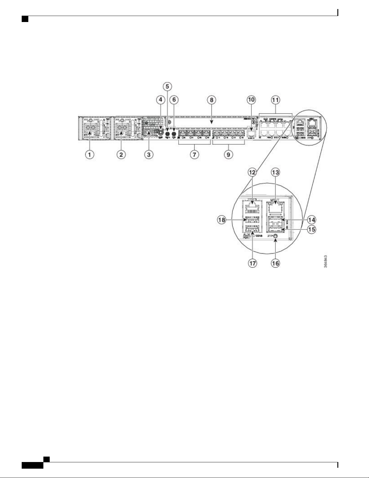
Figure 1: Front Panel of Cisco ASR-920-12SZ-IM Router —With DC Power Supply
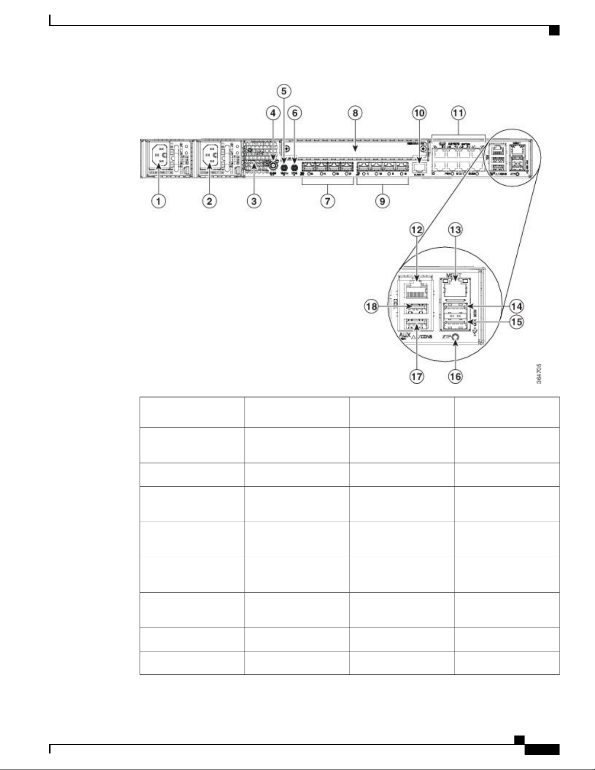
Figure 2: Front Panel of Cisco ASR-920-12SZ-IM Router —With AC Power Supply
Cisco ASR-920-12SZ-IM Aggregation Services Router Hardware Installation Guide
4
Page 17
Cisco ASR 920 Series Aggregation Services Router Overview
SFP+ Ports
1
Alarm port10Power Supply 0 (AC or
DC)
2
11Power Supply 1 (AC or
DC)
Eight Copper port (1G
PoE)
ToD port12Front Air-Inlet Area3
4
Management Port13GNSS RF IN (SMA
threaded connector)
5
USB Memory port14SMB Snap-in connector
(10MHZ)
6
USB Console port15SMB Snap-in connector
(1PPS)
16Four 1G/10G SFP+7
Zero Touch Provisioning
button
RS232 Console port17Interface Module8
RS232 Aux Console port18Four 1G SFP9
Cisco ASR-920-12SZ-IM Aggregation Services Router Hardware Installation Guide
5
Page 18
SFP+ Ports
Cisco ASR 920 Series Aggregation Services Router Overview
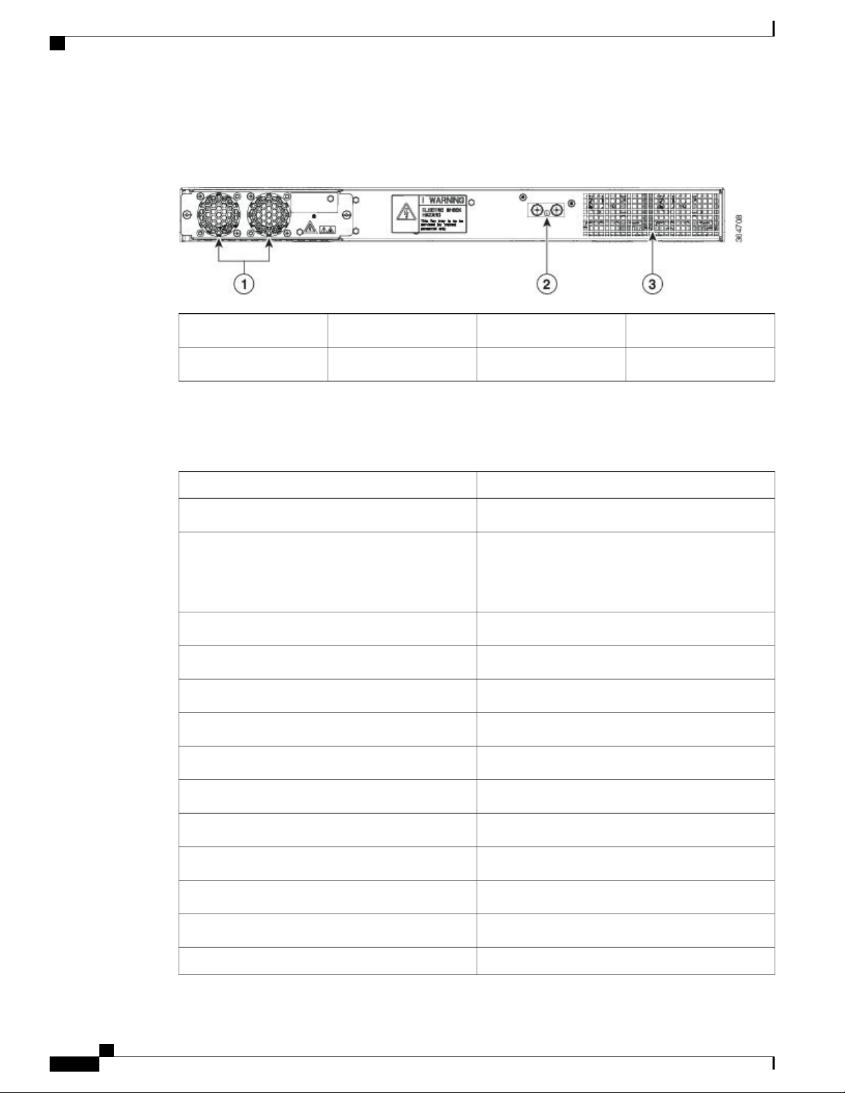
Figure 3: Rear View of Cisco ASR-920-12SZ-IM Router
Air vents3Fan tray1
Grounding lug2
—
The following table describes the other features of Cisco ASR-920-12SZ-IM (AC and DC) Router.
Table 1: Cisco ASR-920-12SZ-IM Router Specifications
ASR-920-12SZ-IMSpecification
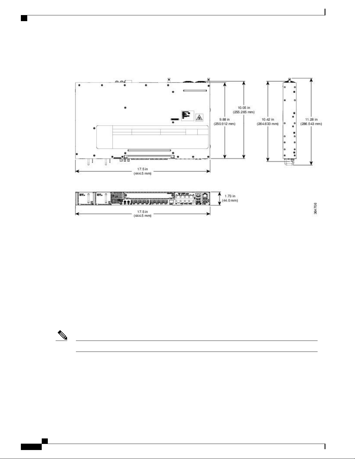
17.5 x 9.88 x 1.73 inchesDimensionWidth x Depth x Height
Weight
Total weight: 4.83 kg
Weight of PSU: 0.59 kg
Weight of Fan: 0.33 kg
One RURack Unit
Front to backAirflow
Front cable accessCable access
60 Gbps, 95 MppsSystem throughput
Power Supply
YesRedundant
YesAC
85V AC to 264V AC, nominal 100/240 VACVoltage Range
47 Hz to 63 Hz, nominal 50/60 HzFrequency Range
360 WMaximum Power
YesDC
Cisco ASR-920-12SZ-IM Aggregation Services Router Hardware Installation Guide
6
Page 19
Cisco ASR 920 Series Aggregation Services Router Overview
SFP+ Ports
ASR-920-12SZ-IMSpecification
-18 VDC to -32 VDC or -40 VDC to -72 VDCVoltage Range
-24 VDC/-48 VDC/-60 VDCNominal Voltage Range
375 WMaximum Power
Operating Temperature
Alarms
Supported Interface Modules
Mounting option
Port Numbering
–40º C to 70º C
4 alarm dry contact inputs (normally open)
•
LED indicators for critical, major, and minor
•
alarms
For more information on these IM modules, see the
Cisco ASR 903 Aggregation Series Router Hardware
Installation Guide .
For more information on the supported IMs, see the
Cisco ASR920 Data sheet.
Front or rear rail 19 or 23 inches
•
ETSI 300 mm open cabinet
•
Wall mount
•
12x1G and 4x10G/1G portsPort Configuration
4x10G SFP+ – Port [12:15]
4x1G SFP – Port [8:11]
8x1G PoE RJ45/Cu ports [0:7]
Ports 12 to 15 are Dual Rate portsCombo Ports
Link/Activity/FaultCopper/1G/10G Port LEDs
Four temperature sensorsTemperature Sensors
External ports for 1PPS/TOD1PPS/ToD
Provides power over EthernetPoE
Connects to the external GPSGNSS
Cisco ASR-920-12SZ-IM Aggregation Services Router Hardware Installation Guide
7
Page 20
External Interfaces
Cisco ASR 920 Series Aggregation Services Router Overview
Figure 4: Cisco ASR-920-12SZ-IM Router—Dimensions
External Interfaces
The external physical interfaces on the front panel of the router are given below:
Network Interfaces
The network interfaces are provided through fixed ports.
• GE SFP ports—supports 100/1000 modes
• GE Copper RJ-45 ports—supports 10/100/1000 operation. All eight copper RJ-45 ports support
PoE/PoE+/UPoE with overall power budget of 180 W.
PoE is not supported when the system is powered with 24 V DC.Note
• 10GE SFP+—supports 10G/1G mode depending on the SFP+/SFP in the network interface slot.
Cisco ASR-920-12SZ-IM Aggregation Services Router Hardware Installation Guide
8
Page 21

Cisco ASR 920 Series Aggregation Services Router Overview
Network Timing Interfaces
• 10Mhz input or output—Miniature coaxial connectors for 10Mhz timing (input or output). You can use
this interfaces with an external GPS device to send or receive clocking from the router
• 1PPS input or output and ToD input or output—This interface is used for input or output of time-of-day
(ToD) and 1PPS pulses. ToD format includes both NTP and IEEE 1588-2008 time formats.
The same RS422 pins for 1PPS and TOD are shared between input and output directions. The direction for
each can be independently configured through software.
• GNSS RF IN—This interface is used to connect the external GPS antenna to the in-built GPS module.
External Alarm Inputs
The router supports four dry contact alarm inputs through an RJ-45 jack on the front panel.
Network Timing Interfaces
• Normally Open—indicates that no current flows through the alarm circuit and the alarm is generated
when the current is flowing.
Each alarm input can be provisioned as critical, major, or minor.
Management Interfaces
The following management interfaces are supported:
Management ENET Port
A single management copper ENET port supporting 100/1000Base-T operation is provided on the front panel.
It uses a standard RJ-45 jack.
RS232 Console Port
The RS232 console port provides transmission (Tx), reception (Rx), and ground (Gnd).
Note
The RS232 console port is enabled only through the Cisco-designed cable adapter USB type A cable to
RJ-45 adapter cable. To use this port, disable the flow control on the terminal.
Do not plug the USB-to-RJ45 adapter cable in the USB Memory port.Caution
Cisco ASR-920-12SZ-IM Aggregation Services Router Hardware Installation Guide
9
Page 22
Power Supply and Fans
USB Console
Cisco ASR 920 Series Aggregation Services Router Overview
A single USB 2.0 Type-A receptacle on the front panel of the router provides console access to ROMMON,
Cisco IOS-XE and diagnostics. While it uses the Type-A connector, it operates as a USB peripheral only for
connection to an external host computer. This interface requires the use of a Type-A to Type-A connector
instead of a standard USB cable.
Note
Use of the USB console is mutually exclusive of the RS232 console port. This interface requires the use
of a Type-A to Type-A USB cable.
USB Mass Storage
A single USB 2.0 Type-A receptacle on the front panel of the router allows external USB mass storage devices,
such as standard USB flash drives. This interface is used to load images, load or store configurations, write
logs, and so on.
More than 8 GB is not supported in ROMMON mode,Note
Zero Touch Provisioning Button
The Zero Touch Provisioning (ZTP) button on the front panel initiates the ZTP process on a short press of
less than eight seconds. Pressing the ZTP button for more than eight seconds causes a board reset.
RS232 Auxiliary Console Port
The RS232 Aux console port provides transmission (Tx), reception (Rx), and ground (Gnd).
Note
The RS232 Aux console port is enabled only through the Cisco-designed cable adapter from USB type
A cable to RJ-45 adapter cable.
This is a debug-only port. it is recommended that this port be used by field service engineers only.Note
Power Supply and Fans
The router supports AC, D, or a combination of both power supplies in a 1+1 redundant configuration.
Cisco ASR-920-12SZ-IM Aggregation Services Router Hardware Installation Guide
10
Page 23
Cisco ASR 920 Series Aggregation Services Router Overview
Table 2: Power Supply Specification
LED Indicators
DC (A920-PWR400-D)AC (A920-PWR400-A)Specification
Note
Note
LED Indicators
Voltage
Current
5A through a standard C16 type
receptacle
24 V – 60 V100 V – 240 V
20A through a two-position
terminal block
375 W360 WInput Power
This product requires surge protection as part of the building installation. To comply with the Telcordia
GR-1089 NEBS standard for electromagnetic compatibility and safety, an external surge protective device
(SPD) is required at the AC power service equipment.
For DC systems, if a surge of more than 500 V is expected, add an appropriate external surge protective
device.
The router has a single fan-tray with four fans. The system is designed to operate at its maximum operating
temperature of 70º C, in case of failure of a single fan operating temperature of 65º C. The fan tray is
field-replaceable.
This section describes the different types of LEDs and their behavior.
PWR and STAT LEDs
The PWR LEDs are available on the front panel. These LEDs provide power on the board (PWR) status.
During power up state, these LEDs provide booting status and report errors.
Note
The digital code signing functionality validates the integrity and authenticity of the ROMMON image
before booting it.
Table 3: PWR and STAT LED Indications
CommentIndicationSTAT LED statePWR LED State
OffAmber
Power in the system is all
right and FPGA
configuration is taking
Permanent Amber/Off
indicates FPGA
configuration failure.
place.
Cisco ASR-920-12SZ-IM Aggregation Services Router Hardware Installation Guide
11
Page 24

LED Indicators
Cisco ASR 920 Series Aggregation Services Router Overview
CommentIndicationSTAT LED statePWR LED State
Green alternatively
Green alternatively
Green alternatively
RedAmber
FPGA Image Validation
Error.
AmberFlashing Amber and
Upgrade FPGA image
System is in unresponsive
state.
—
error, continuing with
Golden FPGA image.
OffFlashing Amber and
FPGA configuration
—
successful and Digital
code signing successfully
validated FPGA image.
Digital code signing
passed the control to
Microloader to boot
ROMMON.
RedFlashing Amber and
Digital code signing
—
reported failure in
ROMMON image
validation.
Flashing AmberFlashing Amber
ZTP process has begun.
Note
A short press of
the ZTP button
Both LEDs turn Green
once provisioning is
complete.
triggers the
provisioning. A
longer press of
more than eight
seconds, resets
the board.
IOS-XE image is booting.OffGreen
GreenGreen
Successfully booted and
—
system is operating
normally.
AmberGreen
A minor alarm or
—
synchronization is in
Holdover or free-running
mode
RedGreen
A major or critical alarm
—
(high temperature
reported for any sensor)
or multiple fan failure.
Cisco ASR-920-12SZ-IM Aggregation Services Router Hardware Installation Guide
12
Page 25
Cisco ASR 920 Series Aggregation Services Router Overview
CPU Management Port LEDs
The LED for the 100/1000 Management port is integrated on the connector itself. There are two LEDs in the
connector—the LED on the left indicates the Link/Activity status and the LED on the right indicates the
duplex status of the link.
Table 4: CPU Management Port LED Indication
LED Indicators
IndicationLED StateLED
Link up in 1000 MbpsGreenLeft
Activity in 1000 MbpsBlinking Green
Link up in 100 MbpsAmber
Activity in 100 MbpsBlinking Amber
SFP LEDs
Each SFP port has an LED indicator.
Table 5: SFP Port LED Indication
number
GreenLabeled same as the SFP port
Blinking Green
Link downOff
Link up in full duplexGreenRight
Link up in half duplexOff
IndicationLED StateLED
Link up in
1000Base-X/100Base-FX
Activity in 1000
Base-X/100Base-FX
Fault/Error/Link downAmber
Administratively downOff
SFP+ LEDs
Each SFP+ port has an LED indicator.
Cisco ASR-920-12SZ-IM Aggregation Services Router Hardware Installation Guide
13
Page 26

LED Indicators
RJ-45 LEDs
Cisco ASR 920 Series Aggregation Services Router Overview
Table 6: SFP+ Port LED Indication
IndicationLED StateLED
Link up in 10G/1GGreenLabeled same as the SFP port
number
Activity in 10G/1GBlinking Green
Fault/Error/Link downAmber
Administratively downOff
There is only one LED on each RJ45 port on the fixed slot (slot 0/0) and this indicates only the link or speed
status. There is no LED to show the Duplex state. However, there are two LEDs for IM RJ45 ports and they
indicate the Link and Duplex state.
Table 7: RJ-45 LED Indication
Power Supply Unit LEDs
Each power supply unit has a corresponding LED on the front panel.
Table 8: PSU LED Indication
IndicationLED State
Link up in 10/100/1000Base-TGreen
Activity in 10/100/1000Base-TBlinking Green
Fault/Error/Link downAmber
Administratively downOff
Power Supply ConditionFAIL LEDPower LED
OffGreen
Power Supply ON; valid
input/output
Red 1Hz blinkingYellow 1Hz blinking
PSU Warning due to OCP, OTP,
UV, OV, OP, abnormal fan
operation
PSU continues to operate
Cisco ASR-920-12SZ-IM Aggregation Services Router Hardware Installation Guide
14
Page 27
Cisco ASR 920 Series Aggregation Services Router Overview
LED Indicators
Power Supply ConditionFAIL LEDPower LED
System–Interface LED Behavior
Table 9: 1G Copper and 1G SFP LED Indication
OnOff
PSU failure due to OCP, OTP, UV,
OV, OP, abnormal fan operation.
No valid output.
OffGreen 1Hz blinking
Valid power present, shutdown by
system.
Input voltage lowOffYellow
No valid power input.OffOff
1G SFP Port LEDs1G Copper Port LEDs (Link)Event
OffOffROMMON
OffOffIOS Shut
AmberAmberIOS No shut (cable disconnect)
Table 10: Dual Rate Port LED Indication
Table 11: Management Port LED Indication
GreenGreenIOS No shut (Link Up)
Dual Rate (1G/10G) Port LEDsEvent
OffROMMON
OffIOS Shut
AmberIOS No shut (cable disconnect)
GreenIOS No shut (Link Up)
Management Port LEDs (Link/Duplex)Event
Green/OffROMMON
Off/OffIOS Shut
Cisco ASR-920-12SZ-IM Aggregation Services Router Hardware Installation Guide
15
Page 28

Online Insertion and Removal
Cisco ASR 920 Series Aggregation Services Router Overview
Management Port LEDs (Link/Duplex)Event
Amber/OffIOS No shut (cable disconnect)
IOS No shut (cable connect)
Online Insertion and Removal
This router supports the following OIR operations:
When an SFP is removed, there is no effect on traffic flowing on other ports.
•
When an SFP is installed, the system initializes that port for operation based upon the current
•
configuration. If the inserted SFP is incompatible with the current configuration for that port, the port
does not become operational until the configuration is updated.
Both power supplies are installed and active and the load may be shared between them or a single PSU
•
could support the whole load. When a power supply is not working or the input cable is removed, the
remaining power supply takes the entire load without disruption.
When a fan tray is removed or replaced, there is no need to power down the router. However, when the
•
fan tray is removed from the router, the router shuts down automatically after some time, depending on
the ambient temperature. The time duration before the router shuts down is shown in the table below:
Green/Green in 1G mode
Amber/Green in 100M mode
Licensing
The router supports the following types of licenses:
• Port Licensing—Port Upgrade license is available as a "Pay as you Grow" model.
6 ports 1GE upgrade license
◦
2 ports 10G upgrade license
◦
Bulk License to enable 12x1port 1GE and 4x10GE ports
◦
Advanced Metro IP Access
•
Metro IP Access
•
Metro Access (default)
•
Feature licensing
•
The following methods are used to activate the above licenses:
• Cisco Software Licensing—The Cisco Software License Activation feature is a set of processes and
components to activate Cisco software feature sets by obtaining and validating fee-based Cisco software
licenses.
Cisco ASR-920-12SZ-IM Aggregation Services Router Hardware Installation Guide
16
Page 29

Cisco ASR 920 Series Aggregation Services Router Overview
Licensing
Note
Licenses generated by the Cisco Software Licensing are tied to the UDI of the chassis and a corresponding
watchtower device certificate (WDC) is stored in the system.
• Cisco Smart Licensing—Smart Licensing is usage-based licensing where devices register with the Cisco
Secure server.
Cisco ASR-920-12SZ-IM Aggregation Services Router Hardware Installation Guide
17
Page 30

Licensing
Cisco ASR 920 Series Aggregation Services Router Overview
Cisco ASR-920-12SZ-IM Aggregation Services Router Hardware Installation Guide
18
Page 31

CHAPTER 2
Preparing for Installation
This chapter describe how to prepare for the installation of the router at your site.
Safety Guidelines, page 20
•
Safety Warning Statements, page 20
•
Safety Guidelines for Personal Safety and Equipment Protection, page 20
•
Safety Precautions for Module Installation and Removal, page 21
•
Safety with Electricity, page 21
•
Power Supply Considerations, page 22
•
Preventing ESD Damage, page 22
•
Site Planning, page 23
•
Air Flow Guidelines, page 24
•
Floor Loading Considerations, page 26
•
Site Power Guidelines, page 27
•
Electrical Circuit Requirements, page 27
•
Site Cabling Guidelines, page 27
•
Asynchronous Terminal Connections, page 28
•
Interference Considerations, page 28
•
Installation Checklist, page 31
•
Creating a Site Log, page 32
•
Chassis-Lifting Guidelines, page 33
•
Tools and Equipment, page 33
•
Unpacking and Verifying the Shipped Contents, page 34
•
Cisco ASR-920-12SZ-IM Aggregation Services Router Hardware Installation Guide
19
Page 32

Safety Guidelines
Safety Guidelines
Before you begin the installation, review the safety guidelines in this chapter to avoid injuring yourself or
damaging the equipment.
In addition, before replacing, configuring, or maintaining the router, review the safety warnings listed in the
Regulatory Compliance and Safety Information document.
Safety Warning Statements
Preparing for Installation
Warning
Warning
Warning
Warning
Before working on a system that has an on/off switch, turn OFF the power and unplug the power cord.
Statement 1
This unit might have more than one power supply connection. All connections must be removed to
de-energize the unit. Statement 1028
This equipment must be grounded. Never defeat the ground conductor or operate the equipment in the
absence of a suitably installed ground conductor. Contact the appropriate electrical inspection authority
or an electrician if you are uncertain that suitable grounding is available. Statement 1024
Before working on equipment that is connected to power lines, remove jewelry (including rings, necklaces,
and watches). Metal objects will heat up when connected to power and ground and can cause serious burns
or weld the metal object to the terminals. Statement 43
For other standard warning messages and their translations, see the Regulatory Compliance and Safety
Information for the Cisco ASR 920 Series Aggregation Services Router document.
Safety Guidelines for Personal Safety and Equipment Protection
The following guidelines help ensure your safety and protect the equipment. This list does not include all the
potentially hazardous situations. Therefore, you should be on alert.
Before moving the system, always disconnect all the power cords and interface cables.
•
Never assume that power is disconnected from a circuit; always check.
•
Before and after installation, keep the chassis area clear and dust free.
•
Keep tools and assembly components away from walk areas where you or others could trip over them.
•
Do not work alone if potentially hazardous conditions exist.
•
Do not perform any action that creates a potential hazard to people or makes the equipment unsafe.
•
Cisco ASR-920-12SZ-IM Aggregation Services Router Hardware Installation Guide
20
Page 33

Preparing for Installation
Safety Precautions for Module Installation and Removal
Do not wear loose clothing that may get caught in the chassis.
•
When working under conditions that may be hazardous to your eyes, wear safety glasses.
•
Safety Precautions for Module Installation and Removal
To see the safety precautions for module installation and removal, see the Regulatory Compliance and Safety
Information for the Cisco ASR 920 Series Aggregation Services Router document.
Safety with Electricity
To see the safety with electricity, see the Regulatory Compliance and Safety Information for the Cisco ASR
920 Series Aggregation Services Router document.
When working on equipment powered by electricity, follow these guidelines:
• Locate the room’s emergency power-off switch. If an electrical accident occurs, you will be able to
quickly turn off the power.
Before starting work on the system, turn off the DC main circuit breaker and disconnect the power
•
terminal block cable.
Before doing the following, disconnect all power:
•
Working on or near power supplies
◦
Installing or removing a router chassis or network processor module
◦
Performing most hardware upgrades
◦
Never install equipment that appears damaged.
•
Carefully examine your work area for possible hazards, such as moist floors, ungrounded power extension
•
cables, and missing safety grounds.
Never assume that power is disconnected from a circuit; always check.
•
Never perform any action that creates a potential hazard to people or makes the equipment unsafe.
•
If an electrical accident occurs, proceed as follows:
•
Use caution, and do not become a victim yourself.
◦
Turn off power to the router.
◦
If possible, send another person to get medical aid. Otherwise, determine the condition of the
◦
victim, and then call for help.
Determine whether the person needs rescue breathing or external cardiac compressions; then take
◦
appropriate action.
In addition, use the following guidelines when working with any equipment that is disconnected from a power
source, but still connected to telephone wiring or network cabling:
Never install telephone wiring during a lightning storm.
•
Cisco ASR-920-12SZ-IM Aggregation Services Router Hardware Installation Guide
21
Page 34

Power Supply Considerations
Never install telephone jacks in wet locations unless the jack is specifically designed for it.
•
Never touch uninsulated telephone wires or terminals unless the telephone line is disconnected at the
•
network interface.
When installing or modifying telephone lines, use caution.
•
Power Supply Considerations
Check the power at your site to ensure that you are receiving clean power (free of spikes and noise). Install a
power conditioner, if necessary.
Preventing ESD Damage
Preparing for Installation
Warning
This equipment needs to be grounded. Use a green and yellow 6 AWG ground wire to connect the host
to earth ground during normal use. Statement 383
Electrostatic discharge (ESD) can damage equipment and impair electrical circuitry. ESD may occur when
electronic printed circuit cards are improperly handled and can cause complete or intermittent failures. When
removing and replacing modules, always follow ESD prevention procedures:
Ensure that the router chassis is electrically connected to earth ground.
•
Wear an ESD-preventive wrist strap, ensuring that it makes good skin contact. To channel unwanted
•
ESD voltages safely to ground, connect the clip to an unpainted surface of the chassis frame. To guard
against ESD damage and shocks, the wrist strap and cord must operate effectively.
If no wrist strap is available, ground yourself by touching a metal part of the chassis.
•
When installing a component, use any available ejector levers or captive installation screws to properly
•
seat the bus connectors in the backplane or midplane. These devices prevent accidental removal, provide
proper grounding for the system, and help to ensure that bus connectors are properly seated.
When removing a component, use available ejector levers or captive installation screws, if any, to release
•
the bus connectors from the backplane or midplane.
Handle components by their handles or edges only; do not touch the printed circuit boards or connectors.
•
Place a removed component board side up on an antistatic surface or in a static-shielding container. If
•
you plan to return the component to the factory, immediately place it in a static-shielding container.
Avoid contact between the printed circuit boards and clothing. The wrist strap only protects components
•
from ESD voltages on the body; ESD voltages on clothing can still cause damage.
Never attempt to remove the printed circuit board from the metal carrier.
•
Note
Cisco ASR-920-12SZ-IM Aggregation Services Router Hardware Installation Guide
22
For the safety of your equipment, periodically check the resistance value of the antistatic wrist strap. It
should be between 1 and 10 Mohm.
Page 35

Preparing for Installation
Site Planning
The sections describe how to plan for the installation of the Cisco ASR 920 Series Router.
General Precautions
Observe the following general precautions when using and working with your router::
Keep your system components away from radiators and heat sources and do not block cooling vents.
•
Do not spill food or liquids on your system components and never operate the product in a wet
•
environment.
Do not push any objects into the openings of your system components. Doing so can cause fire or electric
•
shock by shorting out interior components.
Position system cables and power supply cable carefully. Route system cables and the power supply
•
cable and plug so that they are not stepped on or tripped over. Be sure that nothing else rests on your
system component cables or power cable.
Site Planning
Do not modify power cables or plugs. Consult a licensed electrician or your power company for site
•
modifications. Always follow your local and national wiring rules.
If you turn off your system, wait at least 30 seconds before turning it on again to avoid damage of system
•
components.
Site Planning Checklist
Use the following checklist to perform and account for all the site planning tasks described in this chapter:
The site meets the environmental requirements.
•
• The site’s air conditioning system can compensate for the heat dissipation.
The floor space that the router occupies can support the weight of the system.
•
Electrical service to the site complies with the requirements.
•
The electrical circuit servicing the router complies with the requirements.
•
Consideration has been given to the console port wiring and limitations of the cabling involved, according
•
to TIA/EIA-232F.
The router's Ethernet cabling distances are within the prescribed limitations.
•
The equipment rack in which you plan to install the router complies with prescribed requirements.
•
When selecting the location of the rack, careful consideration must be given to safety, ease of maintenance,
•
and proper airflow.
Cisco ASR-920-12SZ-IM Aggregation Services Router Hardware Installation Guide
23
Page 36

Site Selection Guidelines
Site Selection Guidelines
The router require specific environmental operating conditions. Temperature, humidity, altitude, and vibration
can affect the performance and reliability of the router. The following sections provide specific information
to help you plan for the proper operating environment.
The routers are designed to meet the industry EMC, safety, and environmental standards described in the
Regulatory Compliance and Safety Information for the Cisco ASR 920 Series Router document.
Environmental Requirements
Environmental monitoring of the Cisco ASR 920-24SZ-IM, ASR-920-24SZ-M, ASR-920-24TZ-M Router
protects the system and components from damage caused by excessive voltage and temperature conditions.
To ensure normal operation and avoid unnecessary maintenance, plan and prepare your site configuration
before installation. After installation, make sure that the site maintains the environmental characteristics
described in Cisco ASR-920-12SZ-IM Router Specifications table.
For an outside plant installation (cell site cabinet, hut etc.), it is required that the router be protected against
airborne contaminants, dust, moisture, insects, pests, corrosive gases, polluted air or other reactive elements
present in the outside air. To achieve this level of protection, we recommend that the unit be installed in a
fully sealed enclosure or cabinet. Examples of such cabinets include IP65 cabinets with heat exchanger
complying with Telecordia GR487. Temperature must be maintained within –40º C to 70º C.
The equipment shall be placed inside a space protected from direct outside weather and environmental stresses
by an enclosure, and where the operating climate, as defined by Class 2 of GR-3108-CORE, is between
Preparing for Installation
-40°C (-40°F) and 70°C (158°F)
•
5 and 90% RH
•
Physical Characteristics
Be familiar with the physical characteristics of the router to assist you in placing the system in the proper
location. For more information, see Cisco ASR-920-12SZ-IM Router Specifications table.
Air Flow Guidelines
Cool air is circulated through the router by fans located along the back side of the router.
The internal fans maintain acceptable operating temperatures for the internal components by drawing in cool
air through the vents, and circulating the air through the chassis.
Cisco ASR-920-12SZ-IM Aggregation Services Router Hardware Installation Guide
24
Page 37

Preparing for Installation
Air Flow Guidelines
The direction of air flow is from front-to-back.
Figure 5: Air Flow in the Cisco ASR 920 Series Routers
To ensure adequate air flow through the equipment rack, it is recommended that you maintain a minimum
clearance distance as mentioned below, at all times.
• front clearance—12.7 cm
• rear clearance—14 cm
Note the following points:
Cisco ASR-920-12SZ-IM Aggregation Services Router Hardware Installation Guide
25
Page 38

Air Flow Guidelines for ETSI Rack Installation
When installing the routerouter in a back-to-back position with another device, ensure that there is a
•
minimum of 10 cm air flow clearance between the two devices.
If airflow through the equipment rack and the routers that occupy it is blocked or restricted, or if the
•
ambient air being drawn into the rack is too warm, an overtemperature condition may occur within the
rack and the routers that occupy it.
The site should also be as dust-free as possible. Dust tends to clog the router fans, reducing the flow of
•
cooling air through the equipment rack and the routers that occupy it, thus increasing the risk of an
overtemperature condition.
Enclosed racks must have adequate ventilation. Ensure that the rack is not congested because each router
•
generates heat. An enclosed rack should have louvered sides and a fan to provide cooling air. Heat that
is generated by the equipment near the bottom of the rack can be drawn upward into the intake ports of
the equipment above.
When mounting a chassis in an open rack, ensure that the rack frame does not block the exhaust fans.
•
When rack-installed equipment fails, especially equipment in an enclosed rack, try operating the equipment
•
by itself, if possible. Power off all the other equipment in the rack (and in adjacent racks) to give the
router maximum cooling air and clean power.
Preparing for Installation
Avoid installing the router in a location in which the chassis air intake vents may draw in the exhaust
•
air from adjacent equipment. Consider how the air flows through the router; the airflow direction is front
to back, with ambient air drawn in from the vents located on the sides of the chassis.
Air Flow Guidelines for ETSI Rack Installation
To install a Cisco ASR 920 Series Router in a 2-post or 4-post rack, the front and rear doors of the cabinet
must be removed. It is recommended that you maintain a minimum clearance distance as mentioned below,
at all times.
• front clearance—12.7 cm
• rear clearance—14 cm
If you are mounting the chassis in a 4-post enclosed cabinet, ensure that you have a minimum of 14 cm of
clearance on each side of the chassis.
Floor Loading Considerations
Ensure that the floor under the rack supporting the Cisco ASR 920 Series Routers is capable of supporting
the combined weight of the rack and all the other installed equipment.
To assess the weight of a fully configured Cisco ASR 920 Series Router, see the Cisco ASR-920-12SZ-IM
Router Specifications table.
For additional information about floor loading requirements, see the GR-63-CORE, Network Equipment
Building System (NEBS) Requirements: Physical Protection document.
Cisco ASR-920-12SZ-IM Aggregation Services Router Hardware Installation Guide
26
Page 39

Preparing for Installation
Site Power Guidelines
The router have specific power and electrical wiring requirements. Adhering to these requirements ensures
reliable operation of the system. Follow these precautions and recommendations when planning your site
power for the router:
The redundant power option provides a second, identical power supply to ensure that power to the chassis
•
continues uninterrupted if one power supply fails or input power on one line fails.
Connect each of the two power supplies to a separate input power source. If you fail to do this, your
•
system might be susceptible to total power failure due to a fault in the external wiring or a tripped circuit
breaker.
To prevent a loss of input power, be sure that the total maximum load on each circuit supplying the
•
power supplies is within the current ratings of the wiring and the breakers.
Check the power at your site before installation, and periodically after installation to ensure that you are
•
receiving clean power. Install a power conditioner, if necessary.
Site Power Guidelines
Provide proper grounding to avoid personal injury and damage to the equipment due to lightning striking
•
power lines or due to power surges. The chassis ground must be attached to a central office or other
interior ground system.
Caution
Note
This product requires short-circuit (overcurrent) protection to be provided as part of the building installation.
Install only in accordance with national and local wiring regulations.
The router installation must comply with all the applicable codes, and is approved for use with copper
conductors only. The ground bond-fastening hardware should be of compatible material and preclude
loosening, deterioration, and electrochemical corrosion of hardware and joined material. Attachment of
the chassis ground to a central office or other interior ground system must be made with a 6-AWG gauge
wire copper ground conductor at a minimum.
For information on power specifications, see Power Supply Specification table.
Electrical Circuit Requirements
Each router requires a dedicated electrical circuit. If you equip the router with dual-power feeds, provide a
separate circuit for each power supply to avoid compromising the power redundancy feature.
The ruters can be powered by a DC source or an AC source. Ensure that equipment grounding is present and
observe the power-strip ratings. Make sure that the total ampere rating of all the products plugged into the
power strip does not exceed 80% of the rating.
Site Cabling Guidelines
This section contains guidelines for wiring and cabling at your site. When preparing your site for network
connections to the router, consider the type of cable required for each component, and the cable limitations.
Cisco ASR-920-12SZ-IM Aggregation Services Router Hardware Installation Guide
27
Page 40

Asynchronous Terminal Connections
Consider the distance limitations for signaling, electromagnetic interference (EMI), and connector compatibility.
Possible cable types are fiber, thick or thin coaxial, foil twisted-pair, or unshielded twisted-pair cabling.
Also consider any additional interface equipment you need, such as transceivers, hubs, switches, modems,
channel service units (CSU), or data service units (DSU).
Before you install the router, have all the additional external equipment and cables on hand. For information
about ordering, contact a Cisco customer service representative.
The extent of your network and the distances between the network interface connections depend, in part, on
the following factors:
Signal type
•
Signal speed
•
Transmission medium
•
The distance and rate limits referenced in the following sections are the IEEE-recommended maximum speeds
and distances for signaling purposes. Use this information as a guideline when planning your network
connections prior to installing the router.
If wires exceed the recommended distances, or if wires pass between buildings, give special consideration to
the effect of a lightning strike in your vicinity. The electromagnetic pulse caused by lightning or other
high-energy phenomena can easily couple enough energy into unshielded conductors to destroy electronic
devices. If you have had problems of this sort in the past, you may want to consult experts in electrical surge
suppression and shielding.
Preparing for Installation
Asynchronous Terminal Connections
The router provides a console port to connect a terminal or computer for local console access. The port has
an RJ-45 connector and supports RS-232 asynchronous data with distance recommendations specified in the
IEEE RS-232 standard.
Interference Considerations
When wires are run for any significant distance, there is a risk that stray signals will be induced on the wires
as interference. If interference signals are strong, they may cause data errors or damage to the equipment.
The sections describe the sources of interference and how to minimize their effects on the router.
Electromagnetic Interference
ll the equipment powered by AC current can propagate electrical energy that can cause EMI and possibly
affect the operation of other equipment. The typical sources of EMI are equipment power cords and power
service cables from electric utility companies.
Strong EMI can destroy the signal drivers and receivers in the router and even create an electrical hazard by
causing power surges through the power lines into installed equipment. These problems are rare, but could
be catastrophic.
Cisco ASR-920-12SZ-IM Aggregation Services Router Hardware Installation Guide
28
Page 41

Preparing for Installation
To resolve these problems, you need specialized knowledge and equipment that could consume substantial
time and money. However, you can ensure that you have a properly grounded and shielded electrical
environment, paying special attention to the need for electrical surge suppression.
For information about the electrode magnetic compliance standards supported on the Cisco ASR 920 Series
Router, see the Regulatory Compliance and Safety Information for the Cisco ASR 920 Series Aggregation
Services Router document.
Radio Frequency Interference
When electromagnetic fields act over a long distance, radio frequency interference (RFI) may be propagated.
Building wiring can often act as an antenna, receiving the RFI signals and creating more EMI on the wiring.
If you use twisted-pair cable in your plant wiring with a good distribution of grounding conductors, the plant
wiring is unlikely to emit radio interference. If you exceed the recommended distances, use a high-quality
twisted-pair cable with one ground conductor for each data signal.
Radio Frequency Interference
Lightning and AC Power Fault Interference
If signal wires exceed the recommended cabling distances, or if signal wires pass between buildings, you
should consider the effect that a lightning strike in your vicinity might have on the router.
The electromagnetic pulse (EMP) generated by lightning or other high-energy phenomena can couple enough
energy into unshielded conductors to damage or destroy electronic equipment. If you have previously
experienced such problems, you should consult with RFI and EMI experts to ensure that you have adequate
electrical surge suppression and shielding of signal cables in your Cisco ASR 920 Series Router operating
environment.
Rack-Mounting Guidelines
The sections provide guidelines for rack-mounting.
Precautions for Rack-Mounting
The following rack-mount guidelines are provided to ensure your safety:
Ensure that the rack is level and stable before extending a component from the rack.
•
Ensure that proper airflow is provided to the components in the rack.
•
Do not step on or stand on any component or system when servicing other systems or components in a
•
rack.
When mounting the router in a partially filled rack, load the rack from the bottom to the top, with the
•
heaviest component at the bottom of the rack.
If the rack is provided with stabilizing devices, install the stabilizers before mounting or servicing the
•
unit in the rack.
Cisco ASR-920-12SZ-IM Aggregation Services Router Hardware Installation Guide
29
Page 42

Rack-Mounting Guidelines
Rack Selection Guidelines
The router can be mounted in most two-post or four-post, 19-inch equipment racks that comply with the
Electronic Industries Association (EIA) standard for equipment racks (EIA-310-D 19-inch). The rack must
have at least two posts with mounting flanges to mount the chassis.
Preparing for Installation
Caution
Caution
When mounting a chassis in any type of rack equipment, ensure that the inlet air to the chassis does not
exceed 70° C.
The distance between the center lines of the mounting holes on the two mounting posts must be 18.31 inch ±
0.06 inch (46.50 cm ± 0.15 cm). The rack-mounting hardware included with the chassis is suitable for most
19-inch equipment racks.
Consider installing the router in a rack with the following features:
NEBS-compliant, 19-inch wide (48.3-cm) rack.
•
EIA or European Telecommunications Standards Institute (ETSI) hole patterns in the mounting rails.
•
The required mounting hardware is shipped with the router. If the rack that you plan to install the system
in has metric-threaded rails, you must provide your own metric-mounting hardware.
Perforated top and open bottom for ventilation to prevent overheating.
•
Leveling feet for stability.
•
The router is not recommended to be installed in an enclosed rack because the chassis requires an
unobstructed flow of cooling air to maintain acceptable operating temperatures for its internal components.
If you use an enclosed rack, ensure that the air flow requirements are maintained as discussed in Air Flow
Guidelines.
Equipment Rack Guidelines
The placement of a rack can affect personnel safety, system maintenance, and the system’s ability to operate
within the environmental characteristics. Choose a proper location for the router by following the guidelines
described here.
Locating for Safety
If the Cisco ASR 920 Series Router is the heaviest or the only piece of equipment in the rack, consider installing
it at or near the bottom to ensure that the rack’s center of gravity is as low as possible.
For additional information about the proper placement of electronic equipment, consult the GR-63-CORE,
Network Equipment Building System (NEBS) Requirements: Physical Protection document.
Locating for Easy Maintenance
It is recommended that you maintain a minimum clearance distance as mentioned below, at all times.
• front clearance—12.7 cm
Cisco ASR-920-12SZ-IM Aggregation Services Router Hardware Installation Guide
30
Page 43

Preparing for Installation
Installation Checklist
• rear clearance—10 cm
This space ensures that you can remove the router components and perform routine maintenance and upgrades
easily.
Avoid installing the router in a congested rack and consider how routing of cables from other pieces of
equipment in the same rack could affect access to the router cards.
The front and rear of the chassis must remain unobstructed to ensure adequate airflow and prevent overheating
inside the chassis.
To avoid problems during installation and ongoing operations, follow these general precautions when you
plan equipment locations and connections:
Use the show environment all command regularly to check the internal system status. The environmental
•
monitor continually checks the interior chassis environment; it provides warnings about high temperature
and creates reports on other potentially dangerous occurrences. If warning messages are displayed, take
immediate action to identify the cause, and correct the problem.
Keep the router off the floor and out of areas that collect dust.
•
Follow ESD-prevention procedures to avoid damage to equipment. Damage from static discharge can
•
cause immediate or intermittent equipment failure.
Locating for Proper Airflow
Ensure that the router location has enough airflow to keep the system operating within the environmental
characteristics and the air temperature is sufficient to compensate for the heat dissipated by the system. For
more information, see the Air Flow Guidelines section.
Installation Checklist
To assist you with your installation and to provide a record of what was done by whom and when, photocopy
the Cisco ASR 920 Series Router Installation Checklist shown in the table below. Use this to record the
completion and verification of each procedure. After the checklist is completed, place it in your Site Log along
with the other records pertaining to your new Cisco router.
Table 12: Installation Checklist
Date on which chassis received
Chassis and all accessories
unpacked
Types and numbers of interfaces
verified
DateVerified ByTask
Safety recommendations and
guidelines reviewed
Cisco ASR-920-12SZ-IM Aggregation Services Router Hardware Installation Guide
31
Page 44

Creating a Site Log
Preparing for Installation
DateVerified ByTask
Installation Checklist copied
Site Log established and
background information entered
Site power voltages verified
Site environmental specifications
verified
Required passwords, IP addresses,
device names, and so on, available
Required tools available
Network connection equipment
available
Cable-management brackets
installed (optional, but
recommended)
AC power cables connected to AC
sources and router
DC power cables connected to DC
sources and router
Network interface cables and
devices connected
System power turned on
System boot complete (STATUS
LED is on)
Correct software configuration
displayed after system banner
appears
Creating a Site Log
The Site Log provides a record of all the actions related to installing and maintaining the router. Keep it in
an accessible place near the chassis so that anyone who performs tasks has access to it.
Cisco ASR-920-12SZ-IM Aggregation Services Router Hardware Installation Guide
32
Page 45

Preparing for Installation
Create the Site Log prior to the installation. (See “Site Log” for more information about the Site Log as well
as a sample Site Log that can be used to make copies.)
Chassis-Lifting Guidelines
The chassis is not intended to be moved frequently. Before you install the system, ensure that your site is
properly prepared so that you can avoid having to move the chassis later to accommodate power sources and
network connections.
Each time you lift the chassis or any heavy object, follow these guidelines:
Ensure that your footing is solid, and balance the weight of the chassis between your feet.
•
Lift the chassis slowly; never move suddenly or twist your body as you lift.
•
Keep your back straight and lift with your legs, not your back. If you must bend down to lift the chassis,
•
bend at the knees, not at the waist, to reduce the strain on your back muscles.
Do not remove installed components from the chassis.
•
Chassis-Lifting Guidelines
Always disconnect all external cables before lifting or moving the chassis.
•
Warning
To prevent personal injury or damage to the chassis, never attempt to lift or tilt the chassis using the
handles on modules (such as power supplies, fans, or cards); these types of handles are not designed to
support the weight of the unit. Lift the unit only by using handles that are an integral part of the chassis,
or by grasping the chassis underneath its lower edge. Statement 163
Tools and Equipment
You need the following tools and equipment to install and upgrade the router and its components:
ESD-preventive cord and wrist strap
•
Antistatic mat or antistatic foam
•
Number 1 and Number 2 Phillips-head screwdrivers
•
#12-24 pan-head screws to secure the router to the equipment rack
•
Cables for connecting to the network ports (depending on the configuration)
•
Note
For more information about cable specifications, see the Troubleshooting section.
Ethernet hub, switch, or PC with a network interface card for connecting to the Ethernet ports
•
Console terminal (an ASCII terminal or a PC running terminal emulation software) that is configured
•
for 9600 baud, 8 data bits, no parity, no flow control, and 1stop bit
Console cable for connecting to the console port
•
Cisco ASR-920-12SZ-IM Aggregation Services Router Hardware Installation Guide
33
Page 46

Unpacking and Verifying the Shipped Contents
Ratcheting torque screwdriver with a Phillips head that exerts up to 30-pound force per square inch
•
(in-lb) or 0.02-kilograms force per square millimeter (kgf/mm2) of pressure
Crimping tool as specified by the ground lug manufacturer
•
Wire-stripping tools for stripping both 6-AWG and 12-AWG wires
•
Tape measure and level
•
Only trained and qualified personnel should be allowed to install or replace this equipment. Statement 49Warning
Unpacking and Verifying the Shipped Contents
When you receive your chassis, perform the following steps:
SUMMARY STEPS
Preparing for Installation
DETAILED STEPS
Step 1
Step 2
Step 3
Step 4
Inspect the box for any shipping damage. If there is obvious physical damage, contact your Cisco service representative.
Unpack the Cisco ASR 920-24SZ-IM, ASR-920-24SZ-M, ASR-920-24TZ-M Router.
Perform a visual inspection of the chassis.
Use the table below to check the contents of the Cisco ASR 920-24SZ-IM, ASR-920-24SZ-M, ASR-920-24TZ-M Router
shipping container. Do not discard the shipping container. You will need the container if you move or ship the Cisco
ASR 920-24SZ-IM, ASR-920-24SZ-M, ASR-920-24TZ-M Router in the future.
Table 13: Cisco ASR 920-24SZ-IM, ASR-920-24SZ-M, ASR-920-24TZ-M Router Default Shipping Container Contents
Inspect the box for any shipping damage. If there is obvious physical damage, contact your Cisco service
1.
representative.
Unpack the Cisco ASR 920-24SZ-IM, ASR-920-24SZ-M, ASR-920-24TZ-M Router.
2.
Perform a visual inspection of the chassis.
3.
Use the table below to check the contents of the Cisco ASR 920-24SZ-IM, ASR-920-24SZ-M,
4.
ASR-920-24TZ-M Router shipping container. Do not discard the shipping container. You will need the
container if you move or ship the Cisco ASR 920-24SZ-IM, ASR-920-24SZ-M, ASR-920-24TZ-M Router
in the future.
DescriptionComponent
Chassis (PID: ASR-920-12SZ-IM)
Cisco ASR-920-12SZ-IM Aggregation Services Router Hardware Installation Guide
34
Cisco ASR 920 Series Router chassis
Fan tray (PID: ASR-920-FAN-TRAY). By default, the fan
tray is installed in the chassis.
Page 47

Preparing for Installation
Unpacking and Verifying the Shipped Contents
DescriptionComponent
Accessories kit
Optional equipment
Chassis rack-mount brackets (19-inch EIA) with eight
screws
Two cable guides with two screws
One earth lug with two 10-32 screws
USB Type-A to USB Type-A Male cable
PSU dummy cover (ASR920-PWR-BLANK)
IM dummy cover (ASR900-IMA-BLANK)
One disposable wrist strap (optional)ESD, wrist strap (disposable)
Cisco ASR 920 Series Router Pointer CardDocumentation
Check the container for the following optional equipment:
AC and DC power supplies
•
Note
The AC and DC power supplies are provided
as ordered.
Power cord if an AC power supply was shipped.
•
There are no cords for the DC power supply units.
Note
If you do not specify the type of power
cable, US power cable for the AC router
variant is supplied.
Note
Most Cisco documentation is available online. The Cisco ASR 920 Series Aggregation Services Router Pointer
Card that is shipped with your Cisco ASR 920 Series Router contains links and information about the various
documents that are available online.
Cisco ASR-920-12SZ-IM Aggregation Services Router Hardware Installation Guide
35
Page 48

Unpacking and Verifying the Shipped Contents
Preparing for Installation
Cisco ASR-920-12SZ-IM Aggregation Services Router Hardware Installation Guide
36
Page 49

CHAPTER 3
Installing the Cisco ASR 920 Series Router
This chapter describes how to install the router and includes the following sections:
Prerequisites, page 3-1
•
Installing the Router in a Rack, page 3-2
•
Wall Mounting the Router, page 3-13
•
Installing and Removing SFP Modules, page 3-16
•
Connecting to the Copper Ports, page 3-18
•
Installing the Chassis Ground Connection, page 3-20
•
Installing and Removing the Fan Tray, page 3-22
•
Interface Module Installation, page 3-24
•
Installing the Power Supply, page 3-25
•
Connecting the Router to the Network, page 3-35
•
Prerequisites, page 38
•
Installing the Router in a Rack, page 38
•
Mounting the Router in a Rack, page 45
•
Installing the Router Chassis in the Rack, page 46
•
Attaching the Cable Guides, page 47
•
Wall Mounting the Router, page 49
•
Installing and Removing SFP Modules, page 52
•
Connecting to the Copper Ports, page 55
•
Installing the Chassis Ground Connection, page 57
•
Installing and Removing the Fan Tray, page 60
•
Interface Module Installation, page 63
•
Installing the Power Supply, page 65
•
Cisco ASR-920-12SZ-IM Aggregation Services Router Hardware Installation Guide
37
Page 50

Prerequisites
Connecting the Router to the Network, page 80
•
Prerequisites
Before installing the router, it is important to prepare for the installation by:
Preparing the site (site planning) and reviewing the installation plans or method of procedures (MOP).
•
See Site Planning section.
Unpacking and inspecting the router. See Chassis-Lifting Guidelines section.
•
Gathering the tools and test equipment required to properly install the router. See Tools and Equipment
•
section.
For more instructions on how to prepare for the installation of the router, see Preparing for Installation section.
Installing the Router in a Rack
Installing the Cisco ASR 920 Series Router
Caution
Each Cisco ASR 920 Series Aggregation Services Router router includes rack-mounting brackets. Using the
rack-mounting brackets, you can mount the router in a 19-inch, 23-inch, or an ETSI rack that conforms to the
EIA-310-D specification.
Using the two rack-mounting brackets for mounting, you can recess the router in the equipment rack. This
arrangement provides extra space in front of the router for the cables and allows you to close the doors of
racks equipped with front-close doors.
To attach or replace the rack-mounting brackets, see the Attaching Brackets to the Router section.
The rack-mounting brackets are slotted to allow the router to be mounted in racks with EIA 1.25-inch (3.175-cm)
or WECO 1.0-inch (2.54-cm) hole spacing. When installed in the rack, the router requires one EIA 1.75-inch
(4.4-cm) vertical mounting space (or 1 rack unit [RU]) for mounting (see the Mounting the Router in a Rack
section).
Allow clearance on either side of the router for cooling air to be drawn in through the right side and
circulated through the chassis and out the three-fan exhaust ports mounted on the other side of chassis.
The sections describe how to install the router in a rack. The procedures in this section apply to both horizontal
and vertical mounting of the router in a rack:
Cisco ASR-920-12SZ-IM Aggregation Services Router Hardware Installation Guide
38
Page 51

Installing the Cisco ASR 920 Series Router
Attaching Brackets to the Router
The bracket orientation and the brackets that you use depend on whether you are attaching the brackets for a
19-inch, 23-inch, or an ETSI rack. The following figure shows the types of mounting brackets.
Figure 6: Rack-Mounting Brackets
Attaching Brackets to the Router
Note
23-inch brackets219-inch brackets1
4ETSI-rack brackets3
For 19-inch racks, use part number 700-39959-01 (see Attaching Brackets for 19-Inch Racks section.
•
For 23-inch racks, use part number 700-40065-01 (see Attaching Brackets for 23-Inch Racks section).
•
For ETSI racks, use part number 700-40067-01 (see Attaching Brackets for ETSI Racks section).
•
—
The bracket mounting screws are pre-installed on the router. Depending on the bracket mounting position
of the chassis, you must remove the appropriate screws, fix the bracket, and install the screws again.
Cisco ASR-920-12SZ-IM Aggregation Services Router Hardware Installation Guide
39
Page 52

Attaching Brackets to the Router
Attaching Brackets for 19-Inch Racks
The following figure shows how to attach brackets for 19-inch racks on the router.
Figure 7: Attaching Brackets for 19-Inch Racks
Installing the Cisco ASR 920 Series Router
Cisco ASR-920-12SZ-IM Aggregation Services Router Hardware Installation Guide
40
Page 53

Installing the Cisco ASR 920 Series Router
Attaching Brackets to the Router
Front-mounting position2Phillips flat-head screws1
Rear-mounting position4Mid-mounting position3
Cisco ASR-920-12SZ-IM Aggregation Services Router Hardware Installation Guide
41
Page 54

Attaching Brackets to the Router
Attaching Brackets for 23-Inch Racks
The following figure shows how to attach brackets for 23-inch racks on the router.
Figure 8: Attaching Brackets for 23-Inch Racks
Installing the Cisco ASR 920 Series Router
Cisco ASR-920-12SZ-IM Aggregation Services Router Hardware Installation Guide
42
Page 55

Installing the Cisco ASR 920 Series Router
Attaching Brackets to the Router
Front-mounting position2Phillips flat-head screws1
Rear-mounting position4Mid-mounting position3
Cisco ASR-920-12SZ-IM Aggregation Services Router Hardware Installation Guide
43
Page 56

Attaching Brackets to the Router
Attaching Brackets for ETSI Racks
The following figure shows how to attach brackets for ETSI racks on the router.
Figure 9: Attaching Brackets for ETSI Racks
Installing the Cisco ASR 920 Series Router
Cisco ASR-920-12SZ-IM Aggregation Services Router Hardware Installation Guide
44
Page 57

Installing the Cisco ASR 920 Series Router
Mounting the Router in a Rack
Perform the steps given below to mount the router into the equipment rack.
Mounting the Router in a Rack
Front-mounting position2Phillips flat-head screws1
Rear-mounting position4Mid-mounting position3
Note
SUMMARY STEPS
To secure the router to the equipment rack, you must use the two mounting screws (provided) for each
side or follow your local practices for installing the router into your equipment rack. Ensure that the
rack-mount brackets are securely fastened. For more information, see the Attaching Brackets to the Router
section.
Locate the equipment rack position where you plan to install the router.
1.
Verify that there are no obstructions and ensure that the equipment rack is stabilized.
2.
Determine whether you are mounting the router on a 19-inch, 23-inch, or an ETSI rack. Rack-Mounting
3.
Brackets figure shows the types of mounting brackets.
Determine the mounting position (Front-, Mid-, or Rear-mounting) of the router. (For 19-inch racks, see
4.
Attaching Brackets for 19-Inch Racks section. For 23-inch racks, see Attaching Brackets for 23-Inch Racks
section. For ETSI racks, see Attaching Brackets for ETSI Racks section.)
Locate the mounting holes of the router.
5.
Align the rack-mounting bracket with the router and position with the four #6-32 x 0.25-inch screws
6.
(provided).
Insert the screws (four places) and tighten using a Number 2 Phillips screwdriver (each side).
7.
Position the router in the equipment rack lining up the bracket holes on the router with the holes on the
8.
rack and secure with four #6-32 x 0.25-inch mounting screws (two on each side).
Tighten the screws using a 1/4-inch flat-blade screwdriver (each side). The recommended maximum torque
9.
is 10 in.-lb.
Cisco ASR-920-12SZ-IM Aggregation Services Router Hardware Installation Guide
45
Page 58

Installing the Router Chassis in the Rack
DETAILED STEPS
Installing the Cisco ASR 920 Series Router
Step 1
Step 2
Step 3
Step 4
Step 5
Step 6
Step 7
Step 8
Step 9
Locate the equipment rack position where you plan to install the router.
Verify that there are no obstructions and ensure that the equipment rack is stabilized.
Determine whether you are mounting the router on a 19-inch, 23-inch, or an ETSI rack. Rack-Mounting Brackets figure
shows the types of mounting brackets.
Determine the mounting position (Front-, Mid-, or Rear-mounting) of the router. (For 19-inch racks, see Attaching
Brackets for 19-Inch Racks section. For 23-inch racks, see Attaching Brackets for 23-Inch Racks section. For ETSI racks,
see Attaching Brackets for ETSI Racks section.)
Locate the mounting holes of the router.
Align the rack-mounting bracket with the router and position with the four #6-32 x 0.25-inch screws (provided).
Insert the screws (four places) and tighten using a Number 2 Phillips screwdriver (each side).
Position the router in the equipment rack lining up the bracket holes on the router with the holes on the rack and secure
with four #6-32 x 0.25-inch mounting screws (two on each side).
Tighten the screws using a 1/4-inch flat-blade screwdriver (each side). The recommended maximum torque is 10 in.-lb.
Installing the Router Chassis in the Rack
Note
Ensure adequate air flow when mounting the router in a rack. For more information, see the Air Flow
Guidelines section.
Note
SUMMARY STEPS
DETAILED STEPS
Step 1
Position the chassis in the rack as follows:
Install the cable guides before installing the router in a 19-inch EIA rack. See the Attaching the Cable
Guides section.
To install the router chassis in the equipment rack, perform these steps:
Position the chassis in the rack as follows:
1.
Align the mounting holes in the bracket (and optional cable guide) with the mounting holes in the equipment
2.
rack.
Install the four M6x12mm zinc-plated steel screws through the holes in the bracket and into the threaded
3.
holes in the equipment rack posts.
Use a tape measure and level to verify that the chassis is installed straight and level.
4.
Cisco ASR-920-12SZ-IM Aggregation Services Router Hardware Installation Guide
46
Page 59

Installing the Cisco ASR 920 Series Router
If the front of the chassis (front panel) is at the front of the rack, insert the rear of the chassis between the mounting
•
posts.
If the rear of the chassis is at the front of the rack, insert the front of the chassis between the mounting posts.
•
Attaching the Cable Guides
Step 2
Step 3
Step 4
Align the mounting holes in the bracket (and optional cable guide) with the mounting holes in the equipment rack.
The following figure shows how to install the router in a 19-inch EIA rack.
Figure 10: Installing the Chassis in a 19-inch EIA Rack
Install the four M6x12mm zinc-plated steel screws through the holes in the bracket and into the threaded holes in the
equipment rack posts.
Use a tape measure and level to verify that the chassis is installed straight and level.
Attaching the Cable Guides
The Cisco ASR 920 Series Router supports the following cable guides:
• A920-CBL-GUIDE (left and right)—help in routing the cables from all components on the front panel
thereby enabling a proper cable-bending radius.
Note
If the chassis is mounted using 19-inch brackets, you must assemble the cable guides before installing the
chassis on the rack.
To install the cable guides, perform these steps:
Cisco ASR-920-12SZ-IM Aggregation Services Router Hardware Installation Guide
47
Page 60

Attaching the Cable Guides
SUMMARY STEPS
DETAILED STEPS
Installing the Cisco ASR 920 Series Router
Position the cable guide-left and cable guide-right against the front of the chassis and align the four screw
1.
holes, as shown in the following figure.
Secure the cable guides with the four M6x12mm screws supplied with the cable kit. The recommended
2.
maximum torque is 3N-m.
Step 1
Position the cable guide-left and cable guide-right against the front of the chassis and align the four screw holes, as shown
in the following figure.
Figure 11: Cable Guide Installation For 19-inch Rack Brackets
Figure 12: Cable Guide Installation For ETSI Rack Brackets
Cisco ASR-920-12SZ-IM Aggregation Services Router Hardware Installation Guide
48
Page 61

Installing the Cisco ASR 920 Series Router
Wall Mounting the Router
Step 2
Secure the cable guides with the four M6x12mm screws supplied with the cable kit. The recommended maximum torque
is 3N-m.
Figure 13: Installing the Cable Guides (As Per the Standard Kit)
Wall Mounting the Router
To install the router on a wall, follow the instructions in these procedures:
Attaching the Brackets to the Router for Wall-Mounting
While wall mounting the router, always ensure that the power supplies are at the top position.Note
Cisco ASR-920-12SZ-IM Aggregation Services Router Hardware Installation Guide
49
Page 62

Mounting Router on the Wall
The following figure shows how to attach a 19-inch bracket to one side of the router. Follow the same steps
to attach the second bracket to the opposite side.
Figure 14: Attaching 19-inch Brackets for Wall Mounting
Installing the Cisco ASR 920 Series Router
Mounting Router on the Wall
For the best support of the router and cables, ensure the router is attached securely to wall studs or to a firmly
attached plywood mounting backboard.
Suitable for mounting on and over a concrete or other non-combustible surface only. Statement 345Warning
Cisco ASR-920-12SZ-IM Aggregation Services Router Hardware Installation Guide
50
Page 63

Installing the Cisco ASR 920 Series Router
Mount the router with the front panel as shown in the following figure.
Figure 15: Mounting the Router on the Wall
Mounting Router on the Wall
When mounting the router vertically, ensure that the power supplies are at the top.Caution
Cisco ASR-920-12SZ-IM Aggregation Services Router Hardware Installation Guide
51
Page 64

Installing and Removing SFP Modules
Installing and Removing SFP Modules
These sections describe how to install and remove SFP modules. The modules are inserted into the SFP module
slots as depicted in Installing an SFP Module into an SFP Module Slot figure. These field-replaceable modules
provide interfaces.
Each port must match the wavelength specifications on the other end of the cable. For reliable communications,
the cable must not exceed the stipulated cable length.
Use only Cisco SFP modules on the Cisco router. Each SFP module has an internal serial EEPROM that is
encoded with security information. This encoding provides a way for Cisco to identify and validate that the
SFP module meets the requirements for the router.
For detailed instructions on installing, removing, and cabling the SFP module, see the SFP module
documentation.
Installing SFP Modules
Installing the Cisco ASR 920 Series Router
Caution
SUMMARY STEPS
The following figure shows an SFP module that has a bale-clasp latch.
We strongly recommend that you do not install or remove fiber-optic SFP modules with cables attached
because of the potential damage to the cables, the cable connector, or the optical interfaces in the SFP
module. Disconnect all cables before removing or installing an SFP module.Removing and installing an
SFP module can shorten its useful life. Do not remove and insert SFP modules more often than is absolutely
necessary.
Figure 16: SFP Module with a Bale-Clasp Latch
To insert an SFP module into the module slot, follow these steps:
Attach an ESD-preventive wrist strap to your wrist and to a bare metal surface on the chassis.
1.
If the SFP module that you are using has the markings, use them to identify the top side of the module.
2.
Align the SFP module in front of the slot opening.
3.
Insert the SFP module into the slot until you feel the connector on the module snap into place in the rear
4.
of the slot.
Insert the cable connector into the SFP module:
5.
Cisco ASR-920-12SZ-IM Aggregation Services Router Hardware Installation Guide
52
Page 65

Installing the Cisco ASR 920 Series Router
DETAILED STEPS
Installing SFP Modules
Step 1
Step 2
Step 3
Step 4
Attach an ESD-preventive wrist strap to your wrist and to a bare metal surface on the chassis.
Some SFP modules identify the top side of the module with send (TX) and receive (RX) markings or arrows that show
the direction of the connection.
If the SFP module that you are using has the markings, use them to identify the top side of the module.
Align the SFP module in front of the slot opening.
Insert the SFP module into the slot until you feel the connector on the module snap into place in the rear of the slot.
Figure 17: Installing an SFP Module into an SFP Module Slot
Step 5
Caution
Do not remove the dust plugs from the fiber-optic SFP module port or the rubber caps from the fiber-optic
cable until you are ready to connect the cable. The plugs and caps protect the SFP module ports and cables
from contamination and ambient light. Store the dust plugs for later use.
Insert the cable connector into the SFP module:
For fiber-optic SFP modules, insert the LC cable into the SFP module.
•
For copper 1000BASE-T SFP modules, insert the RJ-45 cable connector into the SFP module.
•
Cisco ASR-920-12SZ-IM Aggregation Services Router Hardware Installation Guide
53
Page 66

Removing SFP Modules
Removing SFP Modules
To remove an SFP module from a module receptacle, follow these steps:
SUMMARY STEPS
Attach an ESD-preventive wrist strap to your wrist and to a bare metal surface on the chassis.
1.
Disconnect the cable from the SFP module, and insert a dust plug into the cable end.
2.
Unlock and remove the SFP module, as shown in the following figure.
3.
Grasp the SFP module between your thumb and index finger, and carefully remove it from the module
4.
slot.
For fiber-optic SFP modules, insert a dust plug into the optical ports of the SFP module to keep the optical
5.
interfaces clean.
Place the removed SFP module in an antistatic bag or other protective environment.
6.
DETAILED STEPS
Installing the Cisco ASR 920 Series Router
Step 1
Step 2
Step 3
Attach an ESD-preventive wrist strap to your wrist and to a bare metal surface on the chassis.
Disconnect the cable from the SFP module, and insert a dust plug into the cable end.
For reattachment, note which cable connector plug is send (TX) and which is receive (RX).Tip
Unlock and remove the SFP module, as shown in the following figure.
Cisco ASR-920-12SZ-IM Aggregation Services Router Hardware Installation Guide
54
Page 67

Installing the Cisco ASR 920 Series Router
If the module has a bale-clasp latch, pull the bale out and down to eject the module. If the bale-clasp latch is obstructed
and you cannot use your index finger to open it, use a small, flat-blade screwdriver or other long, narrow instrument to
open the bale-clasp latch.
Figure 18: Removing a Bale-Clasp Latch SFP Module
Connecting to the Copper Ports
Step 4
Step 5
Step 6
Grasp the SFP module between your thumb and index finger, and carefully remove it from the module slot.
For fiber-optic SFP modules, insert a dust plug into the optical ports of the SFP module to keep the optical interfaces
clean.
Place the removed SFP module in an antistatic bag or other protective environment.
Connecting to the Copper Ports
Copper ports [0:7] are capable of working 10/100/1000 Mbps.
Note
The router copper ports configure themselves to operate at the speed of attached devices. If the attached
ports do not support autonegotiation, you can explicitly set the speed and duplex parameters. Connecting
devices that do not autonegotiate or that have their speed and duplex parameters manually set can reduce
performance or result in no linkage.
Cisco ASR-920-12SZ-IM Aggregation Services Router Hardware Installation Guide
55
Page 68

Connecting to SFP Modules
SUMMARY STEPS
DETAILED STEPS
Installing the Cisco ASR 920 Series Router
To maximize performance, choose one of these methods for configuring the Ethernet ports:
Let the ports autonegotiate both speed and duplex.
•
Set the port speed and duplex parameters on both ends of the connection.
•
When connecting to workstations, servers, and routers, connect a straight-through cable to an RJ-45
1.
connector on the front panel.When connecting to routers or repeaters, use a crossover cable.
Connect the other end of the cable to an RJ-45 connector on the other device. The port LED turns on when
2.
both the router and the connected device have established link.
Reconfigure and reboot the connected device, if necessary.
3.
Repeat Steps 1 through 3 to connect each device.
4.
Step 1
Step 2
Step 3
Step 4
When connecting to workstations, servers, and routers, connect a straight-through cable to an RJ-45 connector on the
front panel.When connecting to routers or repeaters, use a crossover cable.
Note
Connect the other end of the cable to an RJ-45 connector on the other device. The port LED turns on when both the
router and the connected device have established link.
If the port LED does not turn on, the device at the other end might not be turned on, or there might be a cable problem
or a problem with the adapter installed in the attached device.
Reconfigure and reboot the connected device, if necessary.
Repeat Steps 1 through 3 to connect each device.
You can use the mdix auto interface configuration command in the CLI to enable the automatic
medium-dependent interface crossover (auto-MDIX) feature. When the auto-MDIX feature is enabled, the router
detects the required cable type for copper Ethernet connections and configures the interfaces accordingly.
Therefore, you can use either a crossover or a straight-through cable for connections to a copper 100/1000, or
an SFP module port on the router, regardless of the type of device on the other end of the connection.
On user network interface (UNI) ports, the port LED is green after the link is established.Note
Connecting to SFP Modules
This section describes how to connect to SFP modules. For instructions on how to connect to fiber-optic SFP
modules, see the Connecting to Fiber-Optic SFP Modules section.
For instructions about how to install or remove an SFP module, see the Installing and Removing SFP Modules
section.
Connecting to Fiber-Optic SFP Modules
Follow these steps to connect a fiber-optic cable to an SFP module:
Cisco ASR-920-12SZ-IM Aggregation Services Router Hardware Installation Guide
56
Page 69

Installing the Cisco ASR 920 Series Router
Class 1 laser product. Statement 1008Danger
Installing the Chassis Ground Connection
Caution
SUMMARY STEPS
DETAILED STEPS
Step 1
Step 2
Step 3
Step 4
Remove the rubber plugs from the module port and fiber-optic cable, and store them for future use.
Insert one end of the fiber-optic cable into the SFP module port.
Insert the other cable end into a fiber-optic connector on a target device.
Observe the port status LED.
The LED turns green when the router and the target device have an established link.
If the LED is off, the target device might not be turned on, there might be a cable problem, or there might be problem
with the adapter installed in the target device.
Do not remove the rubber plugs from the SFP module port or the rubber caps from the fiber-optic cable
until you are ready to connect the cable. The plugs and caps protect the SFP module ports and cables from
contamination and ambient light.
Remove the rubber plugs from the module port and fiber-optic cable, and store them for future use.
1.
Insert one end of the fiber-optic cable into the SFP module port.
2.
Insert the other cable end into a fiber-optic connector on a target device.
3.
Observe the port status LED.
4.
If necessary, reconfigure and restart the router or target device.
5.
Step 5
If necessary, reconfigure and restart the router or target device.
Installing the Chassis Ground Connection
Before you connect the power or turn on the power to the router, you must provide an adequate chassis ground
(earth) connection to your router.
This section describes how to ground the chassis. The grounding lug location is on the back panel of the router.
Cisco ASR-920-12SZ-IM Aggregation Services Router Hardware Installation Guide
57
Page 70

Installing the Chassis Ground Connection
Ensure that the grounding lug wire does not cover the fan opening.Tip
Figure 19: Attaching a Grounding Lug to the Rear of the Router
Installing the Cisco ASR 920 Series Router
Grounding-lug1
Caution
Warning
To ensure that the chassis ground connection that you provide is adequate, you need the following parts and
tools:
Ratcheting torque screwdriver with Phillips head that exerts up to 15 in.-lb (1.69 N-m) of torque for
•
attaching the ground wire to the router
Crimping tool as specified by the ground lug manufacturer
•
6-AWG or larger copper wire for the ground wire
•
Wire-stripping tools appropriate to the wire you are using
•
Before making connections to the router, ensure that you disconnect the power at the circuit breaker.
Otherwise, severe injury to you or damage to the router may occur.
Electric Shock Hazard: This fan tray has to be serviced by trained personnel only.Caution
This equipment must be grounded. Never defeat the ground conductor or operate the equipment in the
absence of a suitably installed ground conductor. Contact the appropriate electrical inspection authority
or an electrician if you are uncertain that suitable grounding is available. Statement 1024
Use copper conductors only. Statement 1025Warning
Warning
When installing the unit, the ground connection must always be made first and disconnected last. Statement
42
Cisco ASR-920-12SZ-IM Aggregation Services Router Hardware Installation Guide
58
Page 71

Installing the Cisco ASR 920 Series Router
This unit is to be installed in a restrictive access location and must be permanently grounded to a minimum
6-AWG copper ground wire.
Perform the following procedure to ground the router using a 2-hole lug and the corresponding mounting
point. Most carriers require a minimum 6-AWG ground connection. Verify your carrier’s requirements for
the ground connection.
SUMMARY STEPS
If your ground wire is insulated, use a wire-stripping tool to strip the ground wire to 0.5 inch ± 0.02 inch
1.
(12.7 mm ±0.5 mm).
Slide the open end of your 2-hole ground lug over the exposed area of the ground wire.
2.
Using a crimping tool (as specified by the ground lug manufacturer), crimp the ground lug to the ground
3.
wire as shown in the following figure.
Use a Phillips head screwdriver to attach the 2-hole ground lug and wire assembly to the router with the
4.
2 pan-head Phillips head screws.
Connect the other end of the ground wire to a suitable grounding point at your site.
5.
Installing the Chassis Ground Connection
DETAILED STEPS
Step 1
If your ground wire is insulated, use a wire-stripping tool to strip the ground wire to 0.5 inch ± 0.02 inch (12.7 mm ±0.5
mm).
Figure 20: Stripping a Ground Wire
Cisco ASR-920-12SZ-IM Aggregation Services Router Hardware Installation Guide
59
Page 72

Installing and Removing the Fan Tray
Installing the Cisco ASR 920 Series Router
Step 2
Step 3
Step 4
Step 5
Slide the open end of your 2-hole ground lug over the exposed area of the ground wire.
Using a crimping tool (as specified by the ground lug manufacturer), crimp the ground lug to the ground wire as shown
in the following figure.
Figure 21: Crimping a Ground Lug on to the Ground Wire
Use a Phillips head screwdriver to attach the 2-hole ground lug and wire assembly to the router with the 2 pan-head
Phillips head screws.
Connect the other end of the ground wire to a suitable grounding point at your site.
Installing and Removing the Fan Tray
This section describes how to install and remove fan trays.
Installing the Fan Tray
Follow these steps to install the fan tray in the chassis:
Electric Shock Hazard: This fan tray has to be serviced by trained personnel only.Caution
Always wear the ESD wrist strap when installing or uninstalling the fan tray.Caution
Unplug all power sources before performing this procedure.Caution
Cisco ASR-920-12SZ-IM Aggregation Services Router Hardware Installation Guide
60
Page 73

Installing the Cisco ASR 920 Series Router
SUMMARY STEPS
Orient the fan tray so that the captive screws are aligned to the chassis cavity on the back panel. See the
1.
following figure.
Push the fan assembly into the chassis until the power connector seats in the backplane and the captive
2.
installation screws make contact with the chassis.
Tighten the captive installation screws, using a flat-blade or number 2 Phillips-head screwdriver.
3.
DETAILED STEPS
Installing the Fan Tray
Step 1
Orient the fan tray so that the captive screws are aligned to the chassis cavity on the back panel. See the following figure.
Figure 22: Installing the Fan Tray in the Chassis
Step 2
Step 3
Push the fan assembly into the chassis until the power connector seats in the backplane and the captive installation screws
make contact with the chassis.
Tighten the captive installation screws, using a flat-blade or number 2 Phillips-head screwdriver.
Cisco ASR-920-12SZ-IM Aggregation Services Router Hardware Installation Guide
61
Page 74

Removing the Fan Tray
Removing the Fan Tray
To remove the existing fan assembly, follow these steps:
Installing the Cisco ASR 920 Series Router
Caution
SUMMARY STEPS
When removing the fan tray, keep your hands and fingers away from the spinning fan blades. Let the fan
blades stop completely before you remove the fan tray.
Unplug all power sources before performing this procedure.Caution
Always wear the ESD wrist strap when installing or uninstalling the fan tray.Caution
Locate the fan assembly in the chassis. The fan tray is located to the left of the chassis on the rear side.
1.
See the following figure.
Loosen the two fan tray captive installation screws by turning them counterclockwise, using a flat-blade
2.
or number 2 Phillips-head screwdriver.
Grasp the fan assembly with both hands, and pull it outward; rock it gently, if necessary, to unseat the fan
3.
assembly power connector from the backplane.
Pull the fan assembly clear of the chassis, and set it aside.
4.
Cisco ASR-920-12SZ-IM Aggregation Services Router Hardware Installation Guide
62
Page 75

Installing the Cisco ASR 920 Series Router
DETAILED STEPS
Interface Module Installation
Step 1
Locate the fan assembly in the chassis. The fan tray is located to the left of the chassis on the rear side. See the following
figure.
Figure 23: Uninstalling the Fan Tray from the Chassis
Step 2
Step 3
Step 4
Loosen the two fan tray captive installation screws by turning them counterclockwise, using a flat-blade or number 2
Phillips-head screwdriver.
Grasp the fan assembly with both hands, and pull it outward; rock it gently, if necessary, to unseat the fan assembly
power connector from the backplane.
Pull the fan assembly clear of the chassis, and set it aside.
Interface Module Installation
The following sections describe the various tasks of associated with interface module installation:
Cisco ASR-920-12SZ-IM Aggregation Services Router Hardware Installation Guide
63
Page 76

Installing an Interface Module
Installing an Interface Module
Before inserting an interface module, make sure that the chassis is grounded.Caution
SUMMARY STEPS
To insert the interface module, carefully align the edges of the interface module between the upper and
1.
lower edges of the router slot.
Carefully slide the interface module into the router slot until the interface module makes contact with the
2.
backplane.
Tighten the locking thumbscrews on both sides of the interface module. The recommended maximum
3.
torque is 5.5 in.-lb (.62 N-m).
Connect all the cables to each interface module.
4.
Installing the Cisco ASR 920 Series Router
DETAILED STEPS
Step 1
Step 2
Step 3
Step 4
To insert the interface module, carefully align the edges of the interface module between the upper and lower edges of
the router slot.
Carefully slide the interface module into the router slot until the interface module makes contact with the backplane.
Tighten the locking thumbscrews on both sides of the interface module. The recommended maximum torque is 5.5 in.-lb
(.62 N-m).
Connect all the cables to each interface module.
Removing an Interface Module
SUMMARY STEPS
To remove an interface module, disconnect all the cables from the interface module.
1.
Loosen the locking thumbscrews on both sides of the interface module.
2.
Slide the interface module out of the router slot by pulling on the handles. If you are removing a blank
3.
filler plate, pull the blank filler plate completely out of the router slot using the captive screws.
DETAILED STEPS
Step 1
Step 2
Step 3
64
To remove an interface module, disconnect all the cables from the interface module.
Loosen the locking thumbscrews on both sides of the interface module.
Slide the interface module out of the router slot by pulling on the handles. If you are removing a blank filler plate, pull
the blank filler plate completely out of the router slot using the captive screws.
Cisco ASR-920-12SZ-IM Aggregation Services Router Hardware Installation Guide
Page 77

Installing the Cisco ASR 920 Series Router
Installing the Power Supply
The Cisco ASR 920 Router router provides the choice of two different power supplies:
• DC power—The DC power supply uses 2-position terminal block-style connector with positive
latching/securing and labeled connections for +24/48V, GRD, -24/48V. The terminal block connector
is of suitable size to carry the appropriate AWG wire size to handle the input current of the power supply.
No ON/OFF switch is provided.
• AC power—The AC power supply has an IEC 320-type power receptacle and a 15 Amp service connector.
You can use standard right angle power cords with the AC power supply. The power supply includes a
power cord retainer. No ON/OFF switch is provided.
You can install dual power supplies for redundancy.
Installing the Power Supply
Read the installation instructions before connecting the system to the power source. Statement 10Warning
Note
Caution
Products that have an AC power connection are required to have an external surge protective device (SPD)
provided as part of the building installation to comply with the Telcordia GR-1089 NEBS standard for
electromagnetic compatibility and safety.
Do not use interface module and power supply ejector handles to lift the chassis; using the handles to lift
the chassis can deform or damage the handles.
Power Connection Guidelines
This section provides guidelines for connecting the router’s power supplies to the site power source.
Warning
Never defeat the ground conductor or operate the equipment in the absence of a suitably installed ground
conductor. Contact the appropriate electrical inspection authority or an electrician if you are uncertain
that suitable grounding is available. Statement 213
Warning
The plug-socket combination must be accessible at all times because it serves as the main disconnecting
device. Statement 1019
Cisco ASR-920-12SZ-IM Aggregation Services Router Hardware Installation Guide
65
Page 78

Power Connection Guidelines
Installing the Cisco ASR 920 Series Router
Warning
This product requires short-circuit (overcurrent) protection, to be provided as part of the building installation.
Install only in accordance with national and local wiring regulations. Statement 1045
Guidelines for DC-Powered Systems
Basic guidelines for DC-powered systems include the following:
Each chassis power supply should have its own dedicated input power source. The source must comply
•
with the safety extra-low voltage (SELV) requirements in the UL 60950, CSA 60950, EN 60950, and
IEC 60950 standards.
The circuit must be protected by a dedicated two-pole circuit breaker. The circuit breaker should be
•
sized according to the power supply input rating and local or national code requirements.
The circuit breaker is considered the disconnect device and should be easily accessible.
•
The system ground is the power supply and chassis ground.
•
Do not connect the DC return wire to the system frame or to the system-grounding equipment.
•
Use the grounding lug to attach a wrist strap for ESD protection during servicing.
•
If the chassis is powered with -48V grounding of the positive, the it should be done at the power source
•
side and chassis should protected by a dedicated two-pole circuit breaker.
Guidelines for AC-Powered Systems
Basic guidelines for AC-powered systems include the following:
Each chassis power supply should have its own dedicated branch circuit.
•
The circuit breaker should be sized according to the power supply input rating and local or national code
•
requirements.
The AC power receptacles used to plug in the chassis must be the grounding type. The grounding
•
conductors that connect to the receptacles should connect to protective earth ground at the service
equipment.
Preventing Power Loss
Use the following guidelines to prevent power loss to the router:
To prevent loss of input power, ensure that the total maximum load on each circuit supplying the power
•
supplies is within the current ratings of the wiring and breakers.
In some systems, you can use an UPS to protect against power failures at your site. Avoid UPS types
•
that use ferroresonant technology. These UPS types can become unstable with systems such as the Cisco
ASR 920 Series Router, which can have substantial current-draw fluctuations due to bursty data traffic
patterns.
Cisco ASR-920-12SZ-IM Aggregation Services Router Hardware Installation Guide
66
Page 79

Installing the Cisco ASR 920 Series Router
Use the information in the Cisco ASR-920-12SZ-IM Router Specifications table to estimate the power
requirements and heat dissipation of the router based on a given configuration of the router. Determining
power requirements is useful for planning the power distribution system needed to support the router.
Installing the DC Power Supply Module
This equipment is suitable for installation in Network Telecommunications Facilities and locations where the
NEC applies.
This equipment is suitable for installations utilizing the Common Bonding Network (CBN).
The grounding architecture of this product is DC-Isolated (DC-I) for DC-powered products. DC-powered
products have a nominal operating DC voltage of 48 VDC.
Perform the following procedure to install the power supply module:
SUMMARY STEPS
Ensure that the system (earth) ground connection has been made. See the following figure.
1.
If necessary, remove the blank power supply filler plate from the chassis power supply bay opening by
2.
loosening the captive installation screws.
Verify that power to the DC circuit connected to the power supply you are installing is off. To ensure that
3.
power has been removed from the DC circuits, locate the circuit breakers for the DC circuits, switch the
circuit breakers to the OFF position, and tape the circuit-breaker switches in the OFF position.
Grasp the power supply handle with one hand. Place your other hand underneath the power supply. Slide
4.
the power supply into the power supply bay. Make sure that the power supply is fully seated in the bay.
Tighten the captive installation screws of the power supply. The recommended maximum torque is 5.5
5.
in.-lb (0.62 N-m).
Installing the DC Power Supply Module
Cisco ASR-920-12SZ-IM Aggregation Services Router Hardware Installation Guide
67
Page 80

Installing the DC Power Supply Module
DETAILED STEPS
Installing the Cisco ASR 920 Series Router
Step 1
Step 2
Step 3
Step 4
Step 5
Ensure that the system (earth) ground connection has been made. See the following figure.
If necessary, remove the blank power supply filler plate from the chassis power supply bay opening by loosening the
captive installation screws.
Verify that power to the DC circuit connected to the power supply you are installing is off. To ensure that power has
been removed from the DC circuits, locate the circuit breakers for the DC circuits, switch the circuit breakers to the OFF
position, and tape the circuit-breaker switches in the OFF position.
Grasp the power supply handle with one hand. Place your other hand underneath the power supply. Slide the power
supply into the power supply bay. Make sure that the power supply is fully seated in the bay.
Tighten the captive installation screws of the power supply. The recommended maximum torque is 5.5 in.-lb (0.62 N-m).
Figure 24: Installing the DC Power Supply Module
Cisco ASR-920-12SZ-IM Aggregation Services Router Hardware Installation Guide
68
Page 81

Installing the Cisco ASR 920 Series Router
Activating a DC Power Supply Module
Perform the following procedure to activate a DC power supply:
SUMMARY STEPS
Remove the tape from the circuit-breaker router handle, and restore power by moving the circuit-breaker
1.
router handle to the On (|) position.
Verify power supply operation by checking if the respective power supply front panel LED (PS0 or PS1)
2.
is green.
If the LEDs indicate a power problem, see Troubleshooting.
3.
If you are connecting a redundant DC power supply, repeat these steps for the second power source.
4.
DETAILED STEPS
Installing the DC Power Supply Module
Step 1
Remove the tape from the circuit-breaker router handle, and restore power by moving the circuit-breaker router handle
to the On (|) position.
Step 2
Step 3
Step 4
Verify power supply operation by checking if the respective power supply front panel LED (PS0 or PS1) is green.
If the LEDs indicate a power problem, see Troubleshooting.
If you are connecting a redundant DC power supply, repeat these steps for the second power source.
Note
If you are connecting a redundant DC power supply, ensure that each power supply is connected to a separate
power source in order to prevent power loss in the event of a power failure.
Installing the DC Power Cables
Note
When installing DC power supply, use 14 AWG, 90°C wires. Always ensure that the building’s installation
for short-circuit (overcurrent) protection does not exceed 15A.
Cisco ASR-920-12SZ-IM Aggregation Services Router Hardware Installation Guide
69
Page 82

Installing the DC Power Supply Module
Installing the Cisco ASR 920 Series Router
Note
The DC connector or terminal block has an inbuilt screw and cage nut to which a torque of 1.3 to 1.8 N-m
can be applied.
Figure 25: DC Connector With Inbuilt Screw
0.27 inchesC0.97 inchesA
0.81 inchesM0.31 inchesB
To attach the DC power supplies:
SUMMARY STEPS
Locate the terminal block plug.
1.
Insert the DC-input power source wires into the terminal block plug.
2.
Attach the DC supply wires using the designated screws.
3.
Use a ratcheting torque screwdriver to torque the terminal block plug captive screw. See the following
4.
figure.
Cisco ASR-920-12SZ-IM Aggregation Services Router Hardware Installation Guide
70
Page 83

Installing the Cisco ASR 920 Series Router
DETAILED STEPS
Removing the DC Power Supply Module
Step 1
Step 2
Step 3
Step 4
Locate the terminal block plug.
Insert the DC-input power source wires into the terminal block plug.
Attach the DC supply wires using the designated screws.
Use a ratcheting torque screwdriver to torque the terminal block plug captive screw. See the following figure.
Figure 26: Attaching the DC Power Supply Wires
Removing the DC Power Supply Module
This section provides information about removing and replacing the DC power supply.
Warning
Before performing any of the following procedures, ensure that power is removed from the DC circuit.
Statement 1003
Cisco ASR-920-12SZ-IM Aggregation Services Router Hardware Installation Guide
71
Page 84

Removing the DC Power Supply Module
Installing the Cisco ASR 920 Series Router
Warning
SUMMARY STEPS
Only trained and qualified personnel should be allowed to install, replace, or service this equipment.
Statement 1030
Follow these steps to remove and replace the DC power supply:
Before servicing the power supply, switch off the circuit breaker in your equipment area. As an additional
1.
precaution, tape the circuit-breaker switch in the Off position.
Slip on the ESD-preventive wrist strap that was included in the accessory kit.
2.
Switch the power supply circuit-breaker switch to the Off (O) position.
3.
Pull the terminal block plug connector out of the terminal block head in the power supply. See the following
4.
figure.
Loosen the captive screws on the DC power supply.
5.
Grasp the power supply handle. Simultaneously press the power supply lock towards the left and pull the
6.
power supply out from the chassis while supporting it with the other hand.
Cisco ASR-920-12SZ-IM Aggregation Services Router Hardware Installation Guide
72
Page 85

Installing the Cisco ASR 920 Series Router
DETAILED STEPS
Installing the AC Power Supply Module
Step 1
Step 2
Step 3
Step 4
Step 5
Step 6
Before servicing the power supply, switch off the circuit breaker in your equipment area. As an additional precaution,
tape the circuit-breaker switch in the Off position.
Slip on the ESD-preventive wrist strap that was included in the accessory kit.
Switch the power supply circuit-breaker switch to the Off (O) position.
Pull the terminal block plug connector out of the terminal block head in the power supply. See the following figure.
Loosen the captive screws on the DC power supply.
Grasp the power supply handle. Simultaneously press the power supply lock towards the left and pull the power supply
out from the chassis while supporting it with the other hand.
Figure 27: Removing the DC Power Supply Module
Installing the AC Power Supply Module
Follow these steps to install the AC power supply module:
Cisco ASR-920-12SZ-IM Aggregation Services Router Hardware Installation Guide
73
Page 86

Installing the AC Power Supply Module
SUMMARY STEPS
Installing the Cisco ASR 920 Series Router
Ensure that the system (earth) ground connection has been made.
1.
If necessary, remove the blank power supply filler plate from the chassis power supply bay opening by
2.
loosening the captive installation screws.
Grasp the power supply handle with one hand. Place your other hand underneath the power supply. Slide
3.
the power supply into the power supply bay. Make sure that the power supply is fully seated in the bay.
See the following figure.
Slide the AC power supply cord inside the tie of the tie-and-holder and tighten the tie around the power
4.
supply cord.
Plug the power supply cord into the AC power supply.
5.
Cisco ASR-920-12SZ-IM Aggregation Services Router Hardware Installation Guide
74
Page 87

Installing the Cisco ASR 920 Series Router
DETAILED STEPS
Installing the AC Power Supply Module
Step 1
Step 2
Step 3
Ensure that the system (earth) ground connection has been made.
If necessary, remove the blank power supply filler plate from the chassis power supply bay opening by loosening the
captive installation screws.
Grasp the power supply handle with one hand. Place your other hand underneath the power supply. Slide the power
supply into the power supply bay. Make sure that the power supply is fully seated in the bay. See the following figure.
Figure 28: Installing the AC Power Supply Module
Step 4
Step 5
Slide the AC power supply cord inside the tie of the tie-and-holder and tighten the tie around the power supply cord.
Plug the power supply cord into the AC power supply.
Cisco ASR-920-12SZ-IM Aggregation Services Router Hardware Installation Guide
75
Page 88

Installing the AC Power Supply Module
Installing the AC Power Cables
To install the AC power cables in the power supply slots:
SUMMARY STEPS
Plug the power supply cord in the power supply module.
1.
Insert the power supply cord into the tie [1] and tighten the tie around the power supply cord as shown in
2.
[2] in the figure below.
DETAILED STEPS
Installing the Cisco ASR 920 Series Router
Step 1
Step 2
Plug the power supply cord in the power supply module.
Insert the power supply cord into the tie [1] and tighten the tie around the power supply cord as shown in [2] in the figure
below.
Figure 29: Attaching the AC Power Tie-and-Clip Cord
Cisco ASR-920-12SZ-IM Aggregation Services Router Hardware Installation Guide
76
Page 89

Installing the Cisco ASR 920 Series Router
Activating an AC Power Supply Module
Perform the following procedure to activate an AC power supply:
SUMMARY STEPS
Plug the power cord into the power supply.
1.
Connect the other end of the power cord to an AC-input power source.
2.
Verify power supply operation by checking if the respective power supply front panel LED (PS0 or PS1)
3.
is green.
If the LEDs indicate a power problem, see Troubleshooting for troubleshooting information.
4.
If you are connecting a redundant AC power supply, repeat these steps for the second power source.
5.
Removing the AC Power Supply Module
DETAILED STEPS
Step 1
Step 2
Step 3
Step 4
Step 5
Plug the power cord into the power supply.
Connect the other end of the power cord to an AC-input power source.
Verify power supply operation by checking if the respective power supply front panel LED (PS0 or PS1) is green.
If the LEDs indicate a power problem, see Troubleshooting for troubleshooting information.
If you are connecting a redundant AC power supply, repeat these steps for the second power source.
Note
If you are connecting a redundant AC power supply, ensure that each power supply is connected to a separate
power source in order to prevent power loss in the event of a power failure.
Removing the AC Power Supply Module
This section describes how to remove and replace the AC power supply.
Warning
Warning
When you install the unit, the ground connection must always be made first and disconnected last. Statement
1046
Only trained and qualified personnel should be allowed to install, replace, or service this equipment.
Statement 1030
Installation of the equipment must comply with local and national electrical codes. Statement 1074Warning
Follow these steps to remove and replace the AC power supply:
Cisco ASR-920-12SZ-IM Aggregation Services Router Hardware Installation Guide
77
Page 90

Removing the AC Power Supply Module
SUMMARY STEPS
Installing the Cisco ASR 920 Series Router
Disconnect the power cord from the power source. Do not touch any metal on the power cord when it is
1.
still connected to the power supply.
Loosen the tie and remove the power cord from the tie-and holder.
2.
Remove the power cord from the power connection on the power supply. Do not touch the metal prongs
3.
embedded in the power supply.
Grasp the power supply handle. Simultaneously press the power supply lock towards the left and pull the
4.
power supply out from the chassis while supporting it with the other hand.
Cisco ASR-920-12SZ-IM Aggregation Services Router Hardware Installation Guide
78
Page 91

Installing the Cisco ASR 920 Series Router
DETAILED STEPS
Removing the AC Power Supply Module
Step 1
Step 2
Step 3
Step 4
Disconnect the power cord from the power source. Do not touch any metal on the power cord when it is still connected
to the power supply.
Loosen the tie and remove the power cord from the tie-and holder.
Remove the power cord from the power connection on the power supply. Do not touch the metal prongs embedded in
the power supply.
Grasp the power supply handle. Simultaneously press the power supply lock towards the left and pull the power supply
out from the chassis while supporting it with the other hand.
Figure 30: Removing the AC Power Supply Module
Cisco ASR-920-12SZ-IM Aggregation Services Router Hardware Installation Guide
79
Page 92

Powering On the Router
Powering On the Router
After the router is either rack mounted or mounted on the wall, perform these tasks to complete the installation:
Power on the router.
•
Connect the front-panel ports. See the Connecting to SFP Modules section to complete the installation.
•
Connecting the Router to the Network
The sections describe how to connect a router to the network:
Connect only SELV services to all the ports.Note
Installing the Cisco ASR 920 Series Router
Connecting Console Cables
The sections describe how to connect to the router using console cables:
Connecting to the USB Serial Port Using Microsoft Windows
This procedure shows how to connect to the USB serial port using Microsoft Windows.
Note
SUMMARY STEPS
DETAILED STEPS
Install the USB device driver before establishing a physical connection between the router and the PC,
by using the USB console cable plugged into the USB serial port. Otherwise, the connection will fail. For
more information, see the Installing the Cisco USB Device Driver section.
Connect a USB Type A-to-Type A cable to the USB console port. If you are using the USB serial port for
1.
the first time on a Windows-based PC, install the USB driver now according to the instructions in the
following sections:
Connect the USB Type A cable to the PC.
2.
To communicate with the router, start a terminal emulator application, such as Microsoft Windows
3.
HyperTerminal. This software should be configured with the following parameters:
Step 1
80
Connect a USB Type A-to-Type A cable to the USB console port. If you are using the USB serial port for the first time
on a Windows-based PC, install the USB driver now according to the instructions in the following sections:
Note
Cisco ASR-920-12SZ-IM Aggregation Services Router Hardware Installation Guide
You cannot use the USB port and the EIA port concurrently. When the USB port is used, it takes priority over
the EIA port.
Page 93

Installing the Cisco ASR 920 Series Router
Connecting Console Cables
Step 2
Step 3
Connect the USB Type A cable to the PC.
To communicate with the router, start a terminal emulator application, such as Microsoft Windows HyperTerminal. This
software should be configured with the following parameters:
9600 baud
•
8 data bits
•
no parity
•
1 stop-bit
•
no flow control
•
Connecting to the Console Port Using Mac OS X
This procedure describes how to connect a Mac OS X system USB port to the console using the built-in OS
X terminal utility.
SUMMARY STEPS
Use the Finder to choose Applications > Utilities > Terminal.
1.
Connect the OS X USB port to the router.
2.
Enter the following commands to find the OS X USB port number:
3.
Connect to the USB port with the following command followed by the router USB port speed:
4.
DETAILED STEPS
Step 1
Step 2
Step 3
Step 4
Use the Finder to choose Applications > Utilities > Terminal.
Connect the OS X USB port to the router.
Enter the following commands to find the OS X USB port number:
Example:
macbook:user$ cd /dev
macbook:user$ ls -ltr /dev/*usb*
crw-rw-rw- 1 root wheel 9, 66 Apr 1 16:46 tty.usbmodem1a21 DT-macbook:dev user$
Connect to the USB port with the following command followed by the router USB port speed:
Example:
macbook:user$ screen /dev/tty.usbmodem1a21 9600
To disconnect the OS X USB console from the terminal window, enter Ctrl-a followed by Ctrl-\
Cisco ASR-920-12SZ-IM Aggregation Services Router Hardware Installation Guide
81
Page 94

Connecting Console Cables
Connecting to the Console Port Using Linux
This procedure shows how to connect a Linux system USB port to the console using the built-in Linux terminal
utility.
SUMMARY STEPS
Open the Linux terminal window.
1.
Connect the Linux USB port to the router.
2.
Enter the following commands to find the Linux USB port number:
3.
Connect to the USB port with the following command, followed by the router USB port speed:
4.
DETAILED STEPS
Installing the Cisco ASR 920 Series Router
Step 1
Step 2
Step 3
Step 4
Open the Linux terminal window.
Connect the Linux USB port to the router.
Enter the following commands to find the Linux USB port number:
Example:
root@usb-suse# cd /dev
root@usb-suse /dev# ls -ltr *ACM*
crw-r--r-- 1 root root 188, 0 Jan 14 18:02 ttyACM0
root@usb-suse /dev#
Connect to the USB port with the following command, followed by the router USB port speed:
Example:
root@usb-suse /dev# screen /dev/ttyACM0 9600
To disconnect the Linux USB console from the terminal window, enter Ctrl-a followed by : then quit
Installing the Cisco USB Device Driver
A USB device driver must be installed the first time a Microsoft Windows-based PC is connected to the USB
serial port on the router.
This procedure describes how to install the Microsoft Windows USB device driver in Microsoft Windows
XP, Windows Vista, Windows 2000, Windows 7, and Windows 8. Download the driver for your router model
from the Tools and Resources Download Software site, USB Console Software category, at:
https://software.cisco.com/download/
release.html?mdfid=286037604&flowid=71056&softwareid=282855122&release=3.13&relind=AVAILABLE&rellifecycle=&reltype=latest
To download the driver, you must have a valid service contract associated to your Cisco.com profile.Note
Cisco ASR-920-12SZ-IM Aggregation Services Router Hardware Installation Guide
82
Page 95

Installing the Cisco ASR 920 Series Router
SUMMARY STEPS
Unzip the file asr-9xx_usbconsole_drivers.zip.
1.
Double-click xrusbser_ver2100_installer.exe in the XR21x141x-Win-DriversOnly-Vers2.1.0.0/EXE folder.
2.
Click Next. The InstallShield Wizard Completed window is displayed.
3.
Click Finish.
4.
Connect the USB cable to the PC and router USB console ports. Follow the on-screen instructions to
5.
complete the installation of the driver.
XR21V1401 USB UART Device driver successfully installed message is displayed.
6.
DETAILED STEPS
Connecting Console Cables
Step 1
Step 2
Step 3
Step 4
Step 5
Step 6
Unzip the file asr-9xx_usbconsole_drivers.zip.
Double-click xrusbser_ver2100_installer.exe in the XR21x141x-Win-DriversOnly-Vers2.1.0.0/EXE folder.
Installation Wizard GUI is displayed.
Click Next. The InstallShield Wizard Completed window is displayed.
Click Finish.
Connect the USB cable to the PC and router USB console ports. Follow the on-screen instructions to complete the
installation of the driver.
XR21V1401 USB UART Device driver successfully installed message is displayed.
The USB console is ready for use.
Cisco ASR-920-12SZ-IM Aggregation Services Router Hardware Installation Guide
83
Page 96

Connecting Console Cables
Uninstalling the Cisco USB Driver
Figure 31: Connecting the USB Console Cable to the Cisco ASR 920 Series Router
Installing the Cisco ASR 920 Series Router
SUMMARY STEPS
2USB Type-A console port1
USB Type-A to USB
Type-A console cable
This procedure describes how to uninstall the Microsoft Windows USB device driver in Microsoft Windows
XP, Windows Vista, Windows 2000, Windows 7, and Windows 8.
Disconnect the router console terminal before uninstalling the driver.Note
Choose Start > Control Panel > Add or Remove Programs .
1.
Scroll to Windows Driver Package - Exar corporation (xrusbser) Ports and click Remove. The Program
2.
Maintenance window is displayed.
Click Yes to uninstall the driver.
3.
Cisco ASR-920-12SZ-IM Aggregation Services Router Hardware Installation Guide
84
Page 97

Installing the Cisco ASR 920 Series Router
DETAILED STEPS
Connecting to the EIA Console Port
Step 1
Step 2
Choose Start > Control Panel > Add or Remove Programs .
Scroll to Windows Driver Package - Exar corporation (xrusbser) Ports and click Remove. The Program Maintenance
window is displayed.
Step 3
Click Yes to uninstall the driver.
Connecting to the EIA Console Port
Note
SUMMARY STEPS
The US-to-RJ45 adapter cable and the DB9 console cable are not included with the router; they can be
ordered separately from Cisco.
The serial console cable kit is not included with the router; it is ordered separately.Note
To connect a terminal to the EIA Console port on the router, follow these steps:
Connect the USB end of the USB-to RJ-45 cable to the EIA Console port.
1.
Connect the RJ-45 end of the DB-9 adapter cable to the USB-to RJ-45 cable, as shown in the following
2.
figure.
Connect the DB-9 end of the console cable to the DB-9 end of the terminal.
3.
To communicate with the router, start a terminal emulator application, such as Microsoft Windows
4.
HyperTerminal. This software should be configured with the following parameters:
Cisco ASR-920-12SZ-IM Aggregation Services Router Hardware Installation Guide
85
Page 98

Connecting to the EIA Console Port
DETAILED STEPS
Installing the Cisco ASR 920 Series Router
Step 1
Step 2
Connect the USB end of the USB-to RJ-45 cable to the EIA Console port.
Connect the RJ-45 end of the DB-9 adapter cable to the USB-to RJ-45 cable, as shown in the following figure.
Figure 32: Connecting a Modem to the Cisco ASR 920 Series Router
Step 3
Step 4
ComponentLabelComponentLabel
RJ-45 to DB-9 cable3EIA Console port1
Desktop or system4USB-to-RJ45 adapter2
Connect the DB-9 end of the console cable to the DB-9 end of the terminal.
To communicate with the router, start a terminal emulator application, such as Microsoft Windows HyperTerminal. This
software should be configured with the following parameters:
9600 baud
•
8 data bits
•
no parity
•
1 stop-bit
•
no flow control
•
Cisco ASR-920-12SZ-IM Aggregation Services Router Hardware Installation Guide
86
Page 99

Installing the Cisco ASR 920 Series Router
Connecting a Management Ethernet Cable
When using the Ethernet Management port in the default mode (speed-auto and duplex-auto) the port operates
in the auto-MDI/MDI-X mode. The port automatically provides the correct signal connectivity through the
Auto-MDI/MDI-X feature. The port automatically senses a crossover or straight-through cable and adapts to
it.
However, when the Ethernet Management port is configured to a fixed speed (10, 100, or 1000 Mbps) through
command-line interface (CLI) commands, the port is forced to the MDI mode.
When in a fixed-speed configuration and MDI mode:
Use a crossover cable to connect to an MDI port
•
Use a straight-through cable to connect to an MDI-X port
•
Connecting a Management Ethernet Cable
Caution
To comply with the Telcordia GR-1089 NEBS standard for electromagnetic compatibility and safety,
connect the Management Ethernet ports only to intra-building or unexposed wiring or cable. The
intrabuilding cable must be shielded and the shield must be grounded at both ends. The intra-building
port(s) of the equipment or subassembly must not be metallically connected to interfaces that connect to
the OSP or its wiring. These interfaces are designed for use as intra-building interfaces only (Type 2 or
Type 4 ports as described in GR-1089-CORE) and require isolation from the exposed OSP cabling. The
addition of Primary Protectors is not sufficient protection in order to connect these interfaces metallically
to OSP wiring.
Installing and Removing SFP and SFP+ Modules
The Cisco ASR 920 Series Router supports a variety of SFP and SFP+ modules, including optical and Ethernet
modules. For information on how to install and remove SFP and SFP+ modules, see the documentation for
the SFP or SFP+ module at:
http://www.cisco.com/en/US/partner/products/hw/modules/ps5455/prod_installation_guides_list.html
For information about inspecting and cleaning fiber-optic connections, see: http://www.cisco.com/en/US/
partner/tech/tk482/tk876/technologies_white_paper09186a0080254eba.shtml
Caution
We recommend that you wait for 30 seconds between the removal and insertion of an SFP on an interface
module. We recommend this to allow the transceiver software to initialize and synchronize with the Cisco
ASR 920 Series Router. Changing an SFP more quickly could result in transceiver initialization issues
that disable the SFP.
Connecting a USB Flash Device
To connect a USB flash device to the router, insert the memory stick in the USB port labeled USB MEM.
The Flash memory module can be inserted only one way, and can be inserted or removed regardless of whether
the router is powered up or not.
Cisco ASR-920-12SZ-IM Aggregation Services Router Hardware Installation Guide
87
Page 100

Connecting Timing Cables
The following figure shows the USB port connector on the Cisco ASR 920 Series Router.
Figure 33: Flash Token Memory Stick
Removing a USB Flash Device
To remove and replace a USB flash token memory stick from and into a router, follow these steps:
SUMMARY STEPS
Installing the Cisco ASR 920 Series Router
Pull the memory stick from the USB port.
1.
To replace the Cisco USB Flash memory stick, simply insert the module into the USB port labeled USB
2.
MEM. The Flash memory module can be inserted only one way, and can be inserted or removed regardless
of whether the router is powered up or not.
DETAILED STEPS
Step 1
Step 2
Pull the memory stick from the USB port.
To replace the Cisco USB Flash memory stick, simply insert the module into the USB port labeled USB MEM. The
Flash memory module can be inserted only one way, and can be inserted or removed regardless of whether the router is
powered up or not.
This completes the USB Flash memory installation procedure.
Connecting Timing Cables
The section describes how to connect timing cables to the Cisco ASR 920 Series Router:
Connecting Cables to a GPS Interface
The sections describe how to connect cables from the Cisco ASR-920-12SZ-IM Router to a GPS unit for
input or output timing of frequency:
Cisco ASR-920-12SZ-IM Aggregation Services Router Hardware Installation Guide
88
 Loading...