

Page 1

© 2013 Cisco and/or its affiliates. All rights reserved. This document is Cisco Public Information. Page 1 of 54
Cisco Catalyst 3850 Switch
Deployment Guide
Deployment Guide
Page 2

© 2013 Cisco and/or its affiliates. All rights reserved. This document is Cisco Public Information. Page 2 of 54
Contents
Preface ...................................................................................................................................................................... 3
Purpose ................................................................................................................................................................ 3
Audience ............................................................................................................................................................... 3
Conventions .......................................................................................................................................................... 3
Introduction .............................................................................................................................................................. 4
Initializing the Cisco Catalyst 3850 Switch ............................................................................................................ 4
Console Setup ...................................................................................................................................................... 5
Using the USB Console Port ............................................................................................................................ 5
Using the RJ45 Port ......................................................................................................................................... 5
Cisco IOS XE Software Bundle and Packages Overview ..................................................................................... 6
Booting Cisco IOS XE Software ............................................................................................................................ 7
Booting the Switch in Install Mode .................................................................................................................... 7
Booting the Cisco Catalyst 3850 Switch in Bundle Mode ................................................................................. 8
Updating Cisco IOS XE Software .......................................................................................................................... 8
Software Rollback ............................................................................................................................................... 10
Software Clean ................................................................................................................................................... 10
Migration to Install Mode from the Bootloader Prompt ........................................................................................ 14
Cisco Catalyst 3850 Switch Right-to-Use Licensing Model ............................................................................... 16
RTU License Types ............................................................................................................................................ 16
Permanent RTU License ................................................................................................................................ 17
Image-Based License in a Stack .................................................................................................................... 19
AP-Count License in a Stack .......................................................................................................................... 20
License Migration Between Switches ............................................................................................................. 22
Evaluation RTU License ................................................................................................................................. 25
License Usage Monitoring................................................................................................................................... 26
License Storage Management ............................................................................................................................ 27
Cisco Catalyst 3850 Switch Stacking ................................................................................................................... 27
Overview ............................................................................................................................................................. 27
Plug-and-Play Stack Deployment ....................................................................................................................... 29
Deploying Cisco Catalyst 3850 Switch StackWise-480 NSF and SSO ............................................................... 32
Converged Access with the Cisco Catalyst 3850 Switch .................................................................................... 33
Distributed Functions Enable Converged Access ........................................................................................... 33
Logical Hierarchical Groupings of Roles ........................................................................................................ 34
Converged Access Network Design with Cisco Catalyst 3850 Switch ........................................................... 35
Case Study: Configuring Converged Access with the Cisco Catalyst 3850 Switch ........................................ 38
Configuring the Small Branch Deployment ................................................................................................ 38
Configuring the Large Branch or Medium Size Campus Deployment ........................................................ 40
Cisco Catalyst 3850 Switch Database Manager Template ................................................................................. 42
SDM Template Resources: VLAN and Advanced ............................................................................................... 42
SDM Template Configuration .............................................................................................................................. 43
Monitoring SDM Resources ................................................................................................................................ 44
Appendix A: List of Bootloader Commands ........................................................................................................ 45
Appendix B: Cisco Catalyst 3850 Switch Mobility Agent and Mobility Controller Configurations ................. 46
Page 3

© 2013 Cisco and/or its affiliates. All rights reserved. This document is Cisco Public Information. Page 3 of 54
Preface
Purpose
The purpose of this guide is to explain the basic concepts and provide general procedures and commands to
deploy Cisco® Catalyst® 3850 Switches. It does not provide detailed information about these commands.
Audience
This guide is for networking professionals who are responsible for designing, implementing, or administering a
network that includes a standalone Cisco Catalyst 3850 Switch or a Cisco Catalyst 3850 Switch stack, referred to
as the switch. Readers of this guide are expected to have prior experience working with the Cisco IOS® Software
and familiarity with the concepts and terminology of local area networking, wireless local area networking, and
Layer 2 and Layer 3 switching.
Conventions
This publication uses these conventions to convey instructions and information:
●
Command names are in boldface text.
●
System displays are in screen font.
Page 4

© 2013 Cisco and/or its affiliates. All rights reserved. This document is Cisco Public Information. Page 4 of 54
Introduction
The next-generation Cisco Catalyst 3850 Switch meets the current and future demands of enterprise access-layer
networks. As these networks incorporate ever more technologies, they must be secure, scalable, and resilient. The
Cisco Catalyst 3850 Switch offers operational simplicity, scalability, and superb performance. The new Cisco
StackWise-480 stack architecture delivers the industry’s best-in-class stack bandwidth and resiliency.
The Cisco Catalyst 3850 Switch supports the powerful next-generation Cisco IOS XE Software. The modular Cisco
IOS XE Software architecture enables rich, scalable, and cost-effective integrated borderless networking services.
The Cisco Catalyst 3850 Switch is the first stackable access-layer switch that provides both wired and wireless
services on a single Cisco IOS XE Software-based platform.
This guide describes the procedures required to deploy a Cisco Catalyst 3850 Switch:
1. Initializing the Cisco Catalyst 3850 Switch
2. Cisco Catalyst 3850 Switch right-to-use (RTU) licensing model
3. Cisco Catalyst 3850 Switch stacking
4. Converged access with the Cisco Catalyst 3850 Switch
5. Cisco Catalyst 3850 Switch Database Manager (SDM) template
Initializing the Cisco Catalyst 3850 Switch
●
Console setup
●
Cisco IOS XE Software bundle and packages overview
●
Booting Cisco IOS XE Software
●
Updating Cisco IOS XE Software
●
Software rollback
●
Software clean
●
Boot loader upgrade
●
Migration to installed mode
Page 5
© 2013 Cisco and/or its affiliates. All rights reserved. This document is Cisco Public Information. Page 5 of 54
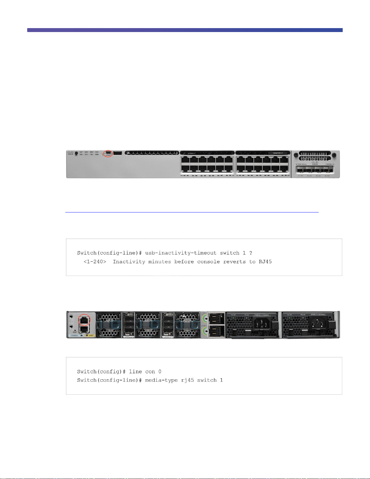
Console Setup
The Cisco Catalyst 3850 Switch (similar to the Cisco Catalyst 3750-X Switch) has two console ports: a USB mini
console port in the front and an RJ45 console port in the rear. You can use either port (but not both) for input.
However, both ports always display the switch output.
The default console port speed setting is 9600 baud, 8 data bits, no parity, 1 stop bit, and no flow control.
Using the USB Console Port
Figure 1. USB Console Port
The USB console port is the default management port and is supported in both install and boot loader modes.
Before using the USB port, download the required driver to your PC from Cisco.com:
http://software.cisco.com/download/release.html?mdfid=282979369&softwareid=282855122&release=3.1.
The USB console port has a configurable inactivity timer that automatically disables the port after a specified period
from 1 to 240 minutes. Use this command to configure the inactivity timeout interval:
Using the RJ45 Port
Figure 2. RJ45 Console Port
To use the RJ45 port, you must configure precedence for it by using these commands:
Configuring precedence for the RJ45 port enables it for input and disables input on the USB console port.
However, switch output is always displayed on both ports.
Page 6
© 2013 Cisco and/or its affiliates. All rights reserved. This document is Cisco Public Information. Page 6 of 54
Image Name
Element
Explanation
Example
platform_name
The name of the platform supported by the Cisco IOS XE Software bundle; caa represents
converged access architecture
cat3k_caa
bundle_feature set
The feature set provided by the Cisco IOS XE Software bundle
universalk9
key_ver
A three-character string indicating that the Cisco IOS XE Software bundle (or the packages it
contains, or both) is digitally signed
SPA
IOS_XE_version
The bundle’s Cisco IOS XE Software release number
3.2.0SE
IOS_image_version
The Cisco IOS Software image version of the Cisco IOS Software package contained in the
bundle
15.0(1)EX
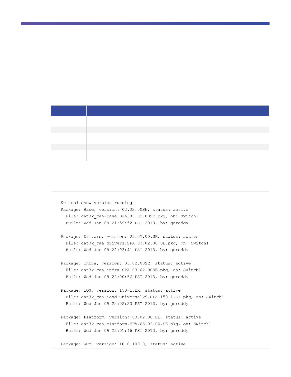
Cisco IOS XE Software Bundle and Packages Overview
The Cisco Catalyst 3850 Switch uses Cisco IOS XE Software. Cisco IOS XE Software is delivered as a bundle that
contains a set of packages. The Cisco IOS XE Software bundle uses this image name convention:
<platform_name>-<bundle_feature_set>.<key_ver>.<IOS-XE_version>.<IOS_image_version> .bin
Example: cat3k_caa-universalk9.SPA.03.02.00.SE.150-1.EX.bin
Explanation of bundle naming convention:
The Cisco IOS XE Software bundle contains a set of packages and a provisioning file, called packages.conf, that
is created automatically during the install process.
The show version running EXEC command displays the current running package(s) version:
Page 7
© 2013 Cisco and/or its affiliates. All rights reserved. This document is Cisco Public Information. Page 7 of 54
Package Name
File Name
Contents
Base
cat3k_caa-base.SPA.03.02.00SE.pkg
Kernel distribution
Drivers
cat3k_caa-drivers.SPA.03.02.00.SE.pkg
Platform drivers
Infra
cat3k_caa-infra.SPA.03.02.00SE.pkg
Infrastructure software, including system
manager, installer, HA manager, and more
Cisco IOS Software
cat3k_caa-iosd-universalk9.SPA.150-1.EX.pkg
Cisco IOS Software image
Platform
cat3k_caa-platform.SPA.03.02.00.SE.pkg
Software not specific to the Cisco IOS Software
platform and stack manager, platform manager,
and more
WCM
cat3k_caa-wcm.SPA.10.0.100.0.pkg
Wireless controller software
The Cisco IOS XE Software bundle includes these packages:
Booting Cisco IOS XE Software
You can boot and run the Cisco IOS XE Software on the Cisco Catalyst 3850 Switch in either of two modes:
●
Install mode (recommended mode of operation)
●
Bundle mode
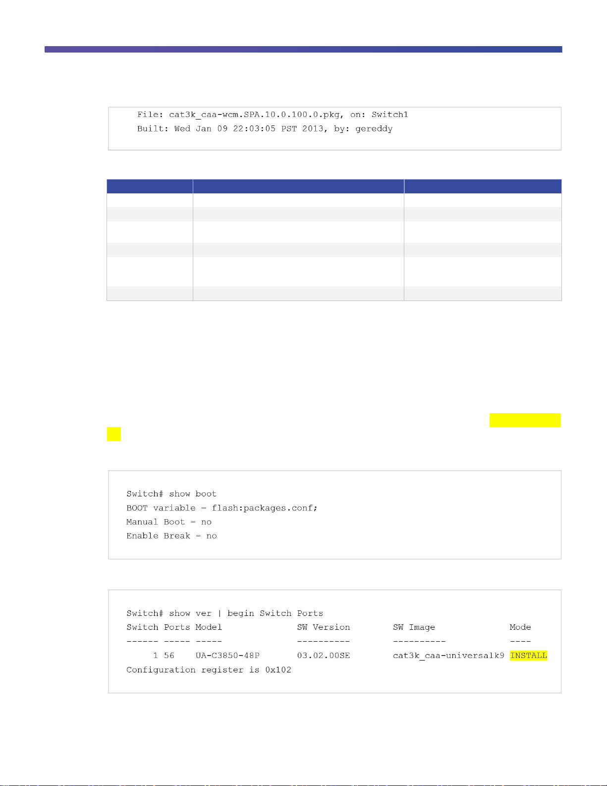
Booting the Switch in Install Mode
Cisco Catalyst 3850 Switches shipped to customers from manufacturing boot up in install mode. The Cisco
Catalyst 3850 Switch is booted in install mode using a package provisioning file packages.conf. Do not modify this
file.
In this example, the Cisco Catalyst 3850 Switch is configured to autoboot from the built-in flash memory:
The show version command output displays the Cisco Catalyst 3850 Switch mode of operation:
The packages and the provisioning file reside in the flash.
Page 8
© 2013 Cisco and/or its affiliates. All rights reserved. This document is Cisco Public Information. Page 8 of 54
Note: Booting in install mode from a USB flash drive or using Trivial File Transfer Protocol (TFTP) is not
supported.
Booting the Cisco Catalyst 3850 Switch in Bundle Mode
Booting a Cisco Catalyst 3850 Switch in bundle mode is just like booting a monolithic Cisco IOS Software image on
a Cisco Catalyst 3750-X Switch.
This command boots the switch in bundle mode:
Note: Booting the switch in bundle mode consumes more memory than booting in install mode because the
packages are extracted from the bundle and copied to the RAM.
You can boot the switch in bundle mode from the built-in flash memory, an external USB drive (usbflash0), or
TFTP. Bundle mode is used to boot a Cisco Catalyst 3850 Switch from the boot loader prompt.
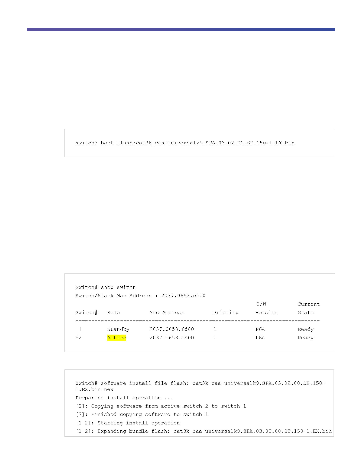
Updating Cisco IOS XE Software
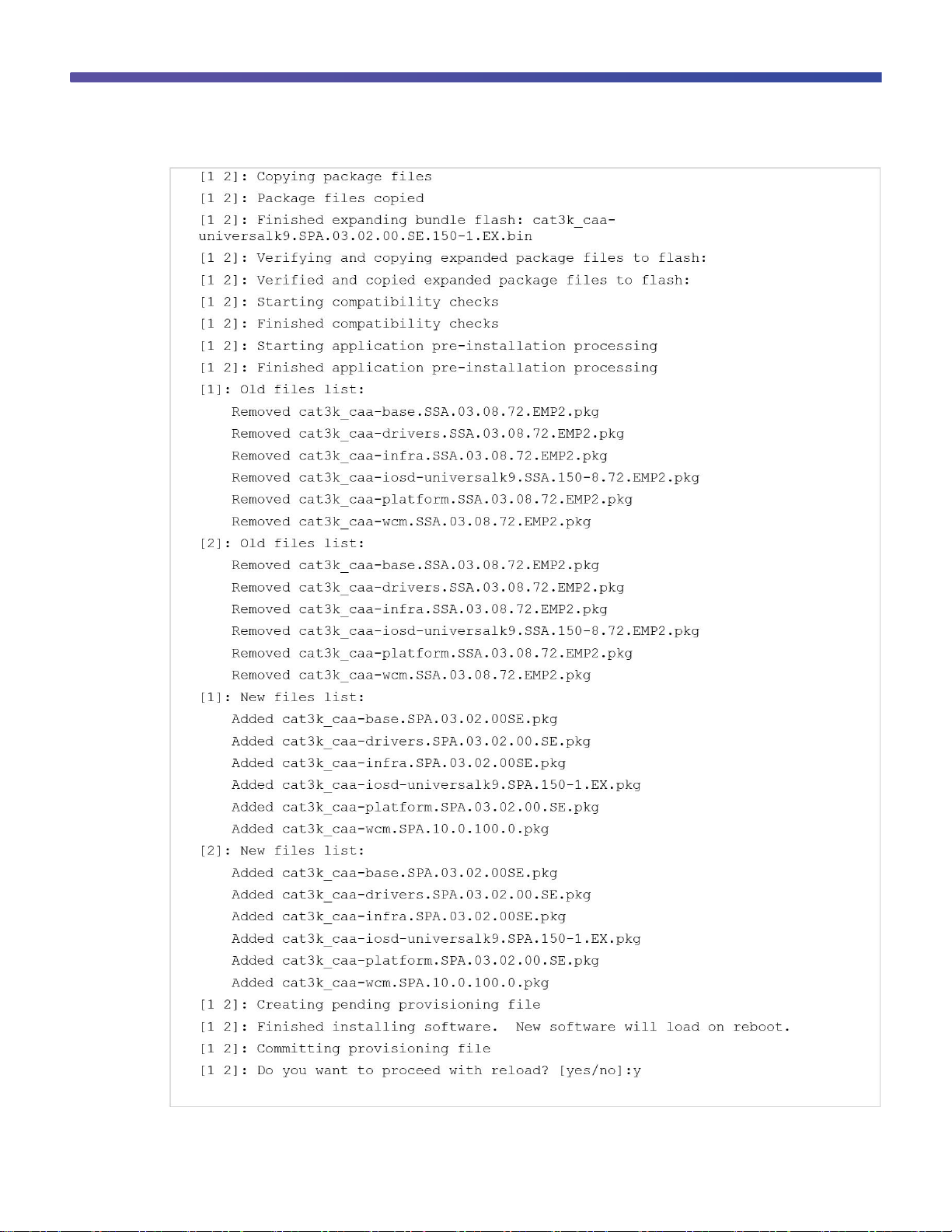
When the switch is in install mode, you can install any new Cisco IOS XE Software bundle by using the software
Install command.
Note: This command works only when the Cisco Catalyst 3850 Switch is booted in install mode.
Use the show switch command to check the status of the switch or switch stack. This example shows the status
of a two-switch stack, where switch 2 is active:
This example shows the command syntax and the console log from a software install in a stack of two switches:
Page 9
© 2013 Cisco and/or its affiliates. All rights reserved. This document is Cisco Public Information. Page 9 of 54
Page 10
© 2013 Cisco and/or its affiliates. All rights reserved. This document is Cisco Public Information. Page 10 of 54
Software Rollback
The software rollback command allows you to revert to an earlier Cisco IOS XE Software package after a
software install. Software rollback is functional only when at least one rollback package with the file name
packages.conf.00- is present. The rollback file is created automatically during the Cisco Catalyst 3850 Switch
Cisco IOS XE Software image update process.
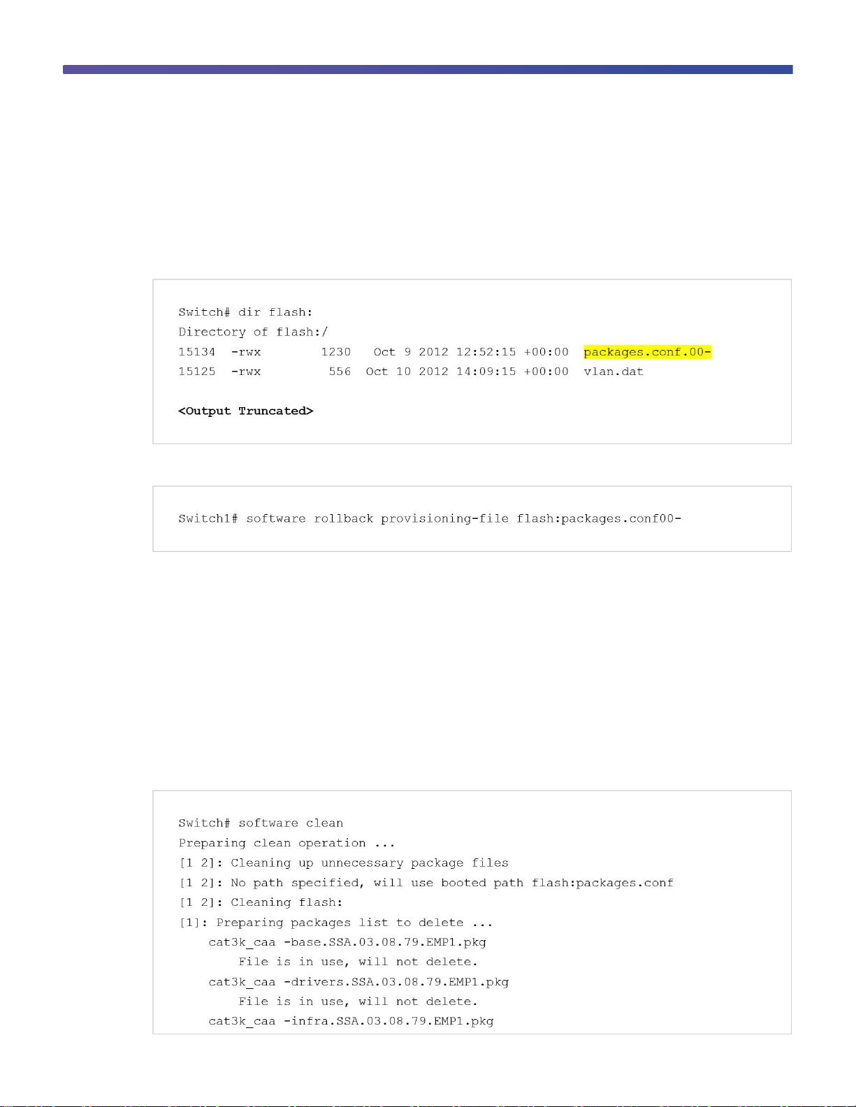
This example shows the flash directory of a switch with an available rollback package:
To revert to an earlier software image, use the software rollback command with the rollback package name:
Software Clean
Flash space in a Cisco Catalyst 3850 Switch can be recovered safely by using the software clean command. This
command deletes any redundant package files (.pkg), bundle files (.bin), or provisioning files (packages.conf*),
without deleting the active .pkg and .conf file.
Do not use the delete command to remove unnecessary files from flash, because you might also delete the active
.pkg or .conf files that are required for booting the switch.
Note: After you use the software clean command, the switch cannot revert to an earlier software image,
because the required rollback files are deleted by this operation.
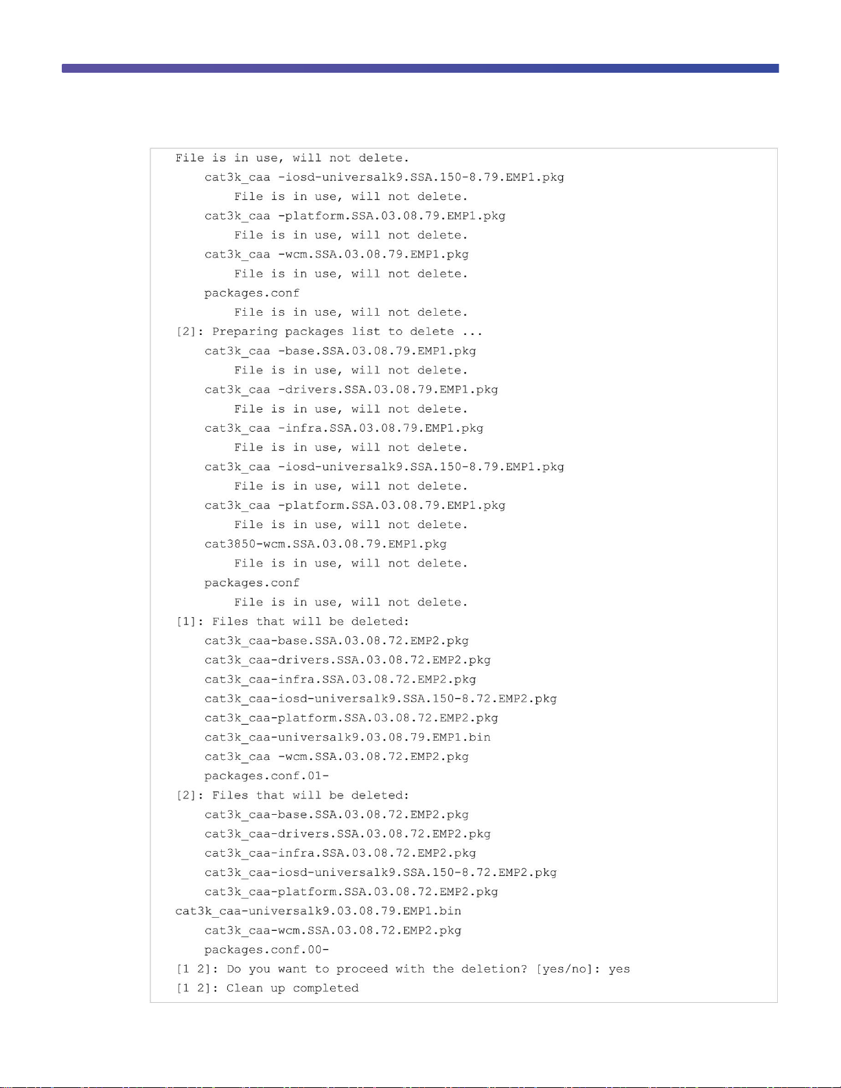
This example shows the results of the software clean command on a stack of two Cisco Catalyst 3850 Switches:
Page 11
© 2013 Cisco and/or its affiliates. All rights reserved. This document is Cisco Public Information. Page 11 of 54
Page 12
© 2013 Cisco and/or its affiliates. All rights reserved. This document is Cisco Public Information. Page 12 of 54
Boot Loader Upgrade
The Cisco Catalyst 3850 Switch shipped from manufacturing is configured to autoboot Cisco IOS XE Software from
the built-in flash and display the autoconfiguration dialog. In special circumstances a boot loader upgrade might be
necessary for a Cisco IOS XE Software image upgrade.
These are the steps to upgrade a Cisco Catalyst 3850 Switch boot loader image:
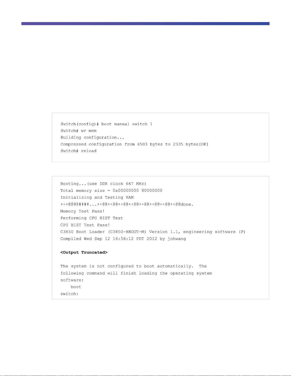
Step 1. Enable manual boot and power cycle the switch.
Enter the boot manual command, along with the switch name or number:
This is a sample of the switch display following a manual boot:
There is a limited set of commands that are supported at the boot loader command prompt. Enter a question mark
to view the available commands.
Note: Appendix A of this guide shows the complete list of boot loader commands.
Page 13
© 2013 Cisco and/or its affiliates. All rights reserved. This document is Cisco Public Information. Page 13 of 54
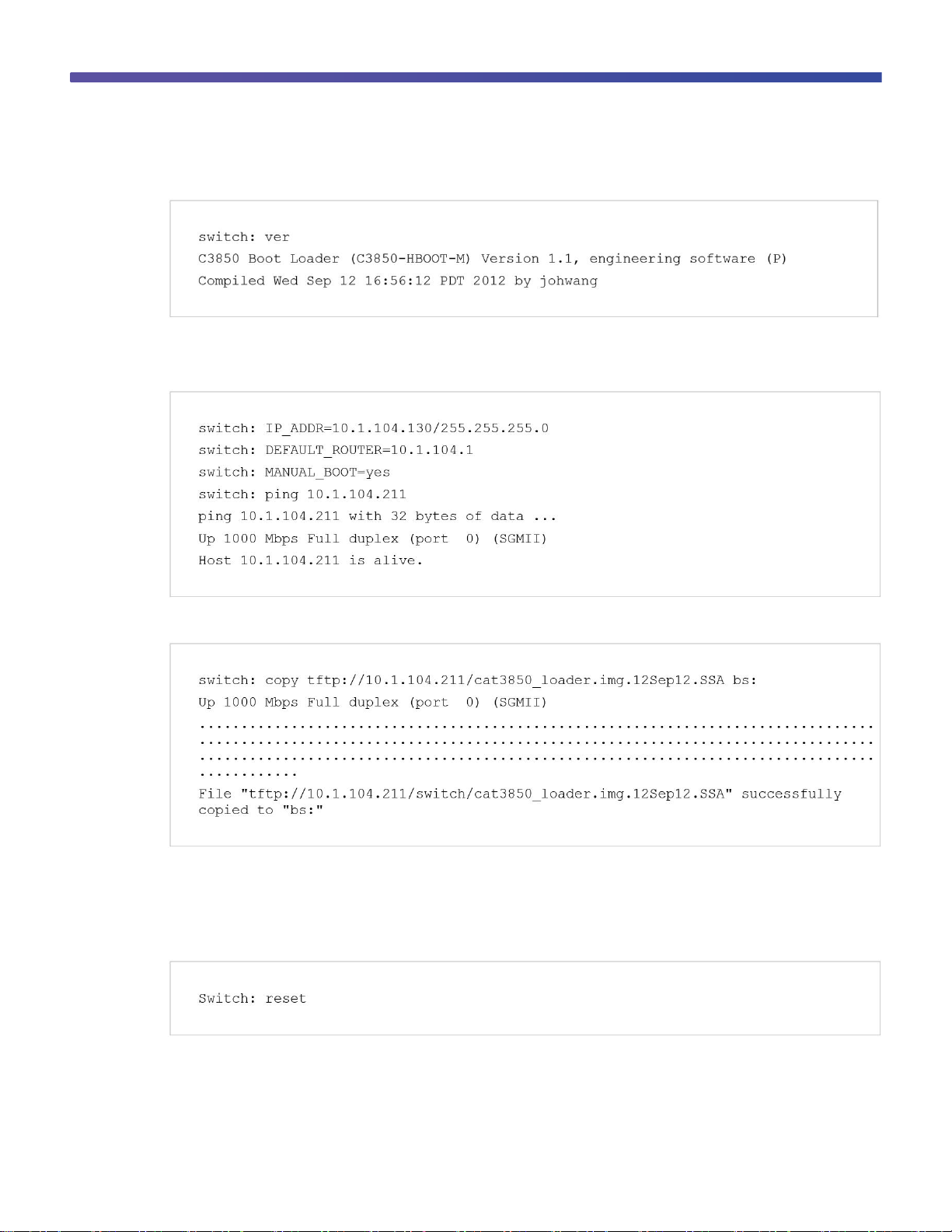
Use the version boot loader command to display the current boot loader version:
Step 2. Load the new boot loader image from a TFTP server.
This example shows how to establish TFTP connectivity to the switch from the boot loader prompt:
This example shows how to copy the boot loader image from TFTP:
Note: You can also copy the boot loader image from a USB flash drive.
Step 3. Reset the switch.
The reset command reloads the switch, and it starts up with the new boot loader image:
To install the Cisco IOS XE Software, migrate from the boot loader prompt to the install mode.
Page 14
© 2013 Cisco and/or its affiliates. All rights reserved. This document is Cisco Public Information. Page 14 of 54
Migration to Install Mode from the Bootloader Prompt
The Cisco IOS XE Software image for the Cisco Catalyst 3850 Switch is distributed as a bundle image. You cannot
copy this bundle directly to the flash and then boot the switch. You must install the Cisco IOS XE Software bundle
into the flash and then boot the switch from the installed software using the install mode. Perform this procedure if
the Cisco IOS XE Software image that resides in the flash memory becomes corrupted.
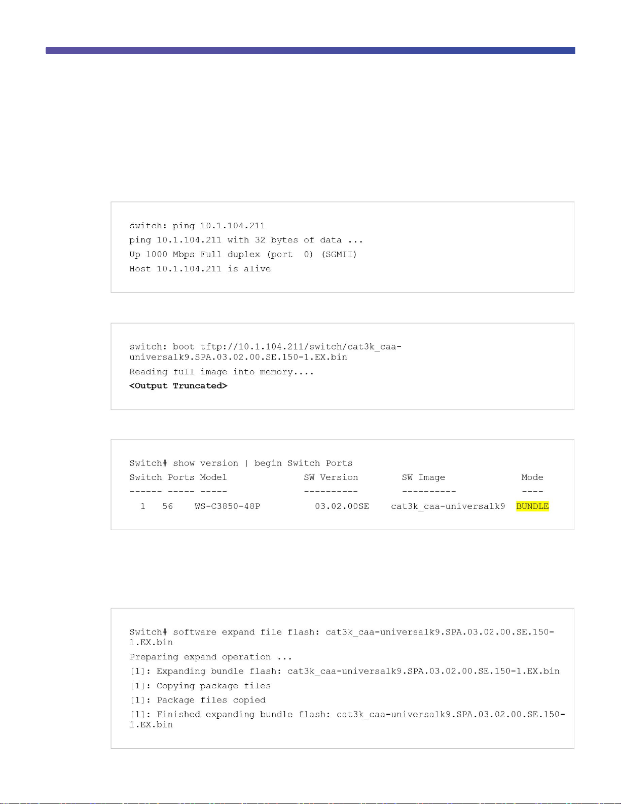
Use the ping command to confirm TFTP connectivity from the boot loader prompt:
Boot the switch from TFTP:
Use the show version command to display the software image version and the mode:
The display shows bundle mode because the switch booted by loading the bundle either from TFTP or from a USB
flash drive.
Copy the final bundle image to the flash either from the TFTP server or from a USB flash drive.
Use the software expand command to expand the bundle image in the flash:
Page 15
© 2013 Cisco and/or its affiliates. All rights reserved. This document is Cisco Public Information. Page 15 of 54
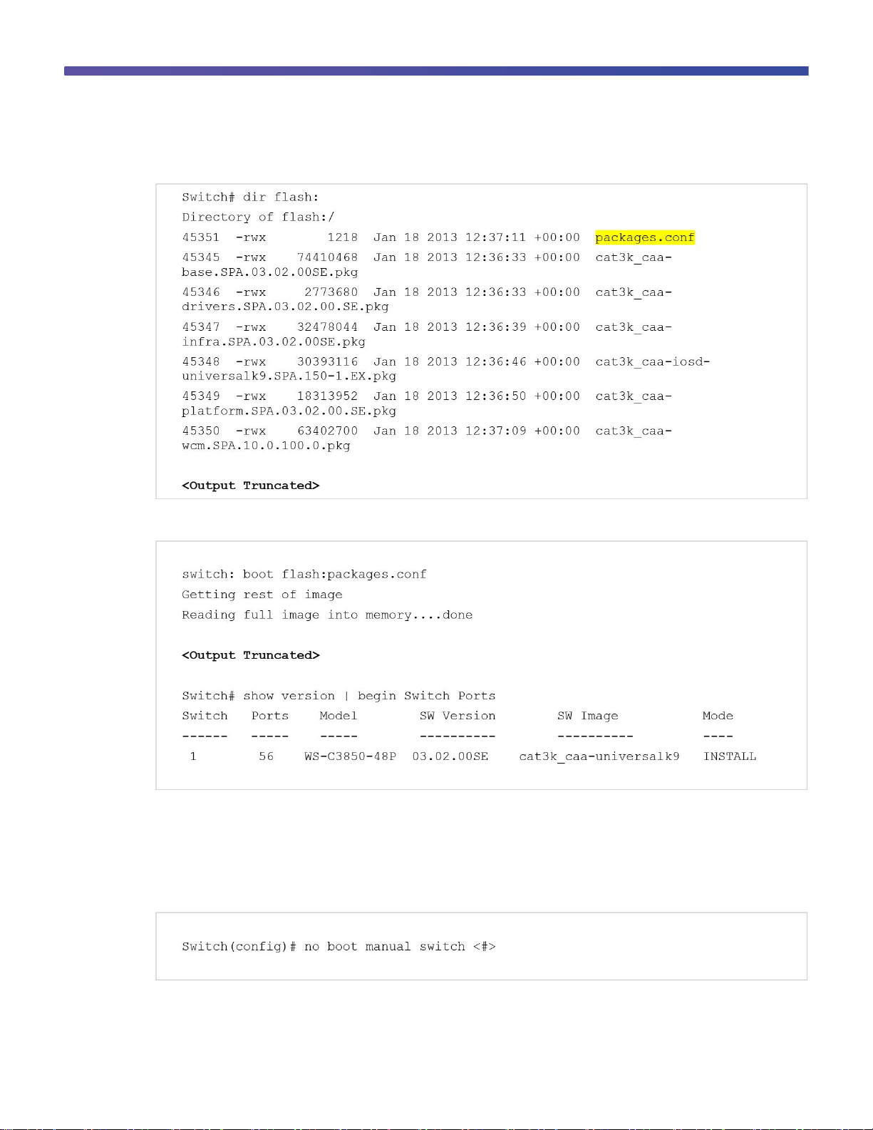
Confirm that the bundle is expanded and packages.conf file is present in the flash memory:
Reload the switch and boot with the newly created flash:packages.conf:
By default, when the software expand command is executed in the active switch of a switch stack, it is executed
on all switches in the stack.
To autoload the installed image, perform these steps:
Use the no boot manual command to disable manual boot:
Page 16
© 2013 Cisco and/or its affiliates. All rights reserved. This document is Cisco Public Information. Page 16 of 54
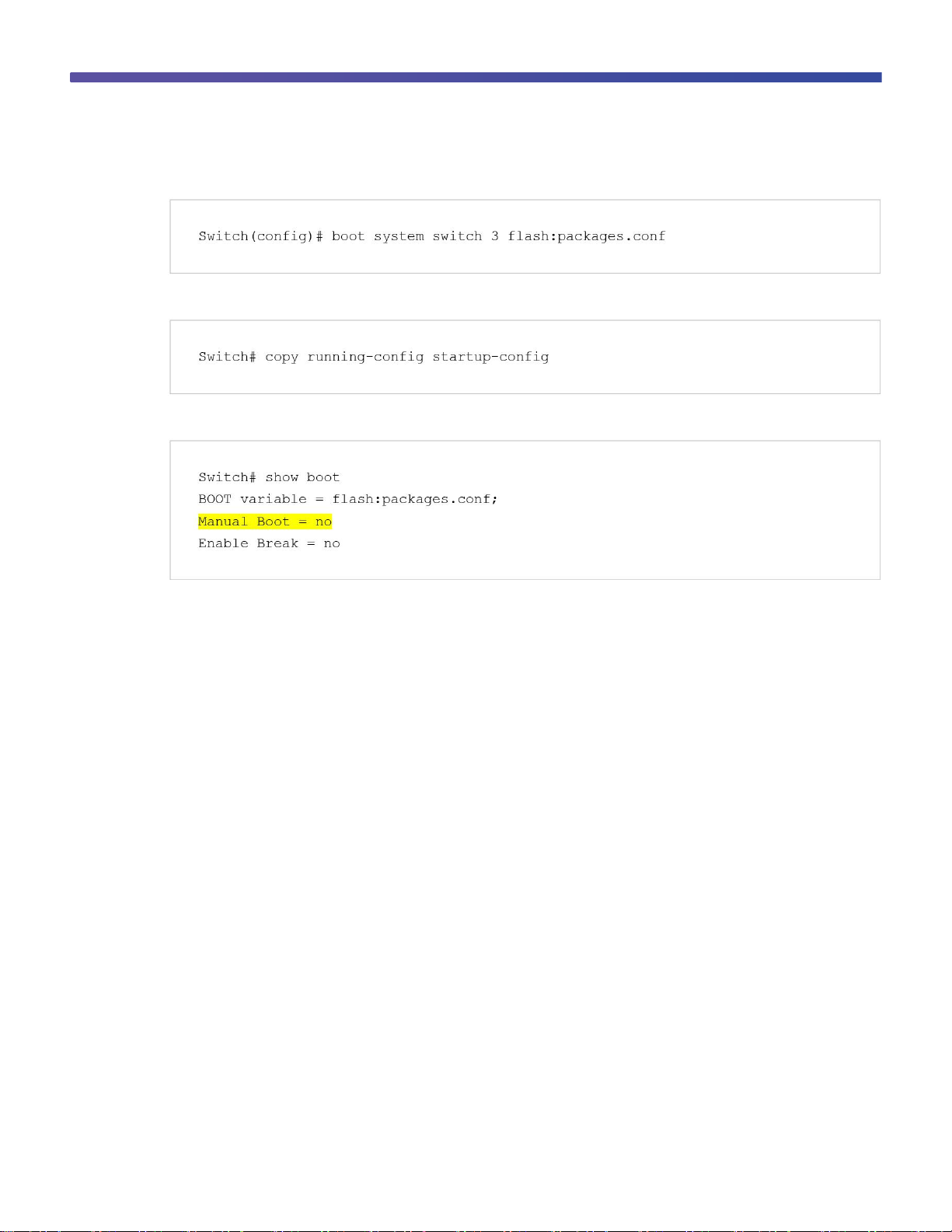
Use the boot system command to modify the boot command to boot from flash:
Use the copy running-config startup-config command to save the configuration:
Use the show boot command to verity that the switch is configured to boot from flash memory:
Cisco Catalyst 3850 Switch Right-to-Use Licensing Model
The Cisco Catalyst 3850 Switch right-to-use (RTU) is a trust-based licensing model designed to give customers the
flexibility to upgrade, downgrade, or move the license for RMA purposes by using simple EXEC commands. The
RTU licensing model allows customers to specify the desired image-based licensing level (LAN Base, IP Base, and
IP Services) and AP-Count on the switch or switch stack through EXEC commands.
About the Cisco Catalyst 3850 Switch RTU license:
●
The RTU license is purchased along with the Cisco Catalyst 3850 Switch (or separately) and is NOT tied to
the unique device identifier (product ID + serial number) of a switch.
●
When you purchase a switch, the license you specified in the purchase order is preinstalled.
●
To upgrade the license, you can order an upgrade license and receive an electronic or printed license. After
accepting the end-user license agreement (EULA), you enable the upgrade by using a simple CLI
command.
●
To transfer RTU licenses from one switch to another, deactivate the license on one switch and activate it on
another.
RTU License Types
There are two main categories of Cisco Catalyst 3850 Switch RTU license: a permanent RTU license and a 90-day
evaluation RTU license.
Page 17
© 2013 Cisco and/or its affiliates. All rights reserved. This document is Cisco Public Information. Page 17 of 54
Permanent RTU License
This is a paid license that does not expire. You can activate permanent RTU licenses after you accept the EULA.
The EULA assumes you have purchased the permanent license. There are two types of permanent RTU licenses:
●
Image-based (or feature set) license
●
Adder AP-Count license
Image-based license: This license is activated by Cisco before the switch is shipped and requires no customer
configuration to enable it. Supported license levels include LAN Base, IP Base, and IP Services.
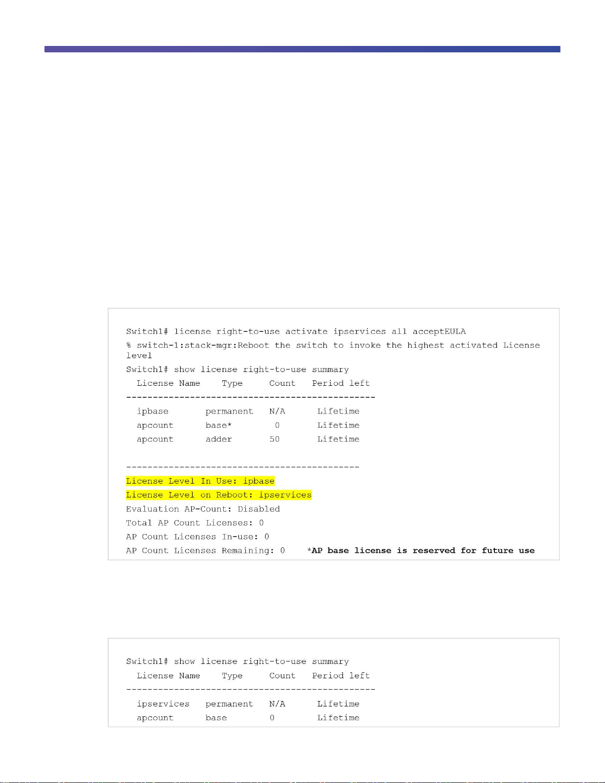
You can upgrade, disable, or move image-based licenses by using the license right-to-use command, either for
individual switches or for all switches in a stack. Reload the switch or stack to activate the highest level license. For
example, if you upgrade the license level from IP Base to IP Services, then the IP services license is activated by
reloading the switch.
This command enables the ipservices license and accepts the EULA on all switches in the stack:
Adder AP-Count license: The adder AP-Count license is an “add as you grow” license. You can add access point
licenses as your network grows. You activate an adder AP-count license by using EXEC commands, and it is
activated without a switch reload.
This example shows the license summary display for a switch with an activated adder AP-Count license:
Page 18

© 2013 Cisco and/or its affiliates. All rights reserved. This document is Cisco Public Information. Page 18 of 54
This example shows the license summary display for a switch with a deactivated adder AP-Count license:
Page 19

© 2013 Cisco and/or its affiliates. All rights reserved. This document is Cisco Public Information. Page 19 of 54
Image-Based License in a Stack
In a Cisco Catalyst 3850 Switch stack, all switches must be at the same image-based license (IP Services/IP
Base/LAN Base) level. The active switch license level is considered the reference, and the member switch
licenses are compared to it. If there is a mismatch, the active switch displays a syslog message saying that the
stack configuration was unsuccessful.
This is an example of the display on the active switch console:
This message appears on the member switch console:
Page 20

© 2013 Cisco and/or its affiliates. All rights reserved. This document is Cisco Public Information. Page 20 of 54
To enable the member switch to join the stack, change the license level of the member switch (switch 2) by
activating the license from the active switch console:
After switch 2 reloads successfully, it joins the stack with the active switch.
AP-Count License in a Stack
AP-Count license is available only with IP Base and IP Services licenses. A Cisco Catalyst 3850 Switch stack can
support a maximum of 50 access points. An AP-Count license is required only if a Cisco Catalyst 3850 Switch is
configured as both a mobility controller and a mobility agent. An AP-Count license is not needed if the Cisco
Catalyst 3850 Switch is configured only as an mobility agent, which is the default configuration. For details on
mobility agent, mobility controller, and other wireless and mobility-related entities, refer to the Cisco Catalyst 3850
Switch converged access section.
Page 21

© 2013 Cisco and/or its affiliates. All rights reserved. This document is Cisco Public Information. Page 21 of 54
The total AP-Count license of a Cisco Catalyst 3850 Switch stack is equal to the sum of all the individual member
AP-Count licenses, up to a maximum of 50 AP-Counts. The total AP-Count license of the stack is affected when
stack members are added or removed:
●
When new members are added to the stack, the total AP-Count license of the stack is automatically
recalculated.
●
When members are removed from the stack, the AP-Count license contributed by the removed switch is
decremented from the total available AP-Count license in the stack.
●
If more AP-Counts are connected than the available AP-Count license, a syslog warning message indicates
this fact without disconnecting the excess connected AP-Counts until a stack reload.
●
After the stack reload, the surplus AP-Count s are removed from the total AP-Count. The following
examples explain the process.
Stack member addition example: A Cisco Catalyst 3850 Switch stack includes 3 switches, each with an APCount license that allows 10 AP-Counts, for a total of 30 supported AP-Counts. When a new Cisco Catalyst 3850
Switch (switch 4) is added to the stack with an AP-Count license allowing 25 AP-Counts, the stack supports a total
of 50 AP-Counts because the total number of 55 access points (30+25) exceeds the stack limit.
Stack member removal example: In the preceding example, if switch 4 is removed from the stack, the AP-Count
license remains at 50 AP-Counts until the stack is reloaded, if 50 AP-Counts are connected and active in the stack.
After reload, the stack returns to its original value of 30 AP-Counts.
When the AP-Count for a stack exceeds 50, a syslog message appears in the active and member switches to
indicate the excess AP-Count:
Page 22

© 2013 Cisco and/or its affiliates. All rights reserved. This document is Cisco Public Information. Page 22 of 54
By default the Cisco Catalyst 3850 Switch stack is configured as a mobility agent. In the wireless licensing model, a
mobility agent is the access point count enforcement point. A mobility controller is the access point count
management point. A Cisco Catalyst 3850 Switch stack can be configured as either a mobility controller or a
mobility agent, or both, depending on the deployment requirement.
Figure 3 shows a typical licensing protocol interaction between an AP-Count, a mobility agent, and a mobility
controller:
Figure 3. Licensing Protocol Call Flow
In a large deployment, a Cisco Catalyst 3850 Switch stack is the mobility agent, and a 5760 wireless controller is
the mobility controller. In a split mobility agent-mobility controller deployment, the AP-Count is managed at the
mobility controller level.
License Migration Between Switches
You can easily migrate RTU licenses between Cisco Catalyst 3850 Switches. Both image-based and AP-Count
licenses can be deactivated from one switch and activated on another switch. To deactivate a license, use the
license right-to-use deactivate EXEC command. To activate a license, use the license right-to-use activate
EXEC command.
These examples illustrate the process:
Example: Switch1 and Switch2 are nonstacked independent Cisco Catalyst 3850 Switches. To move the IP
Services image-based license and 50 AP-Count license from Switch1 to Switch2:
Page 23

© 2013 Cisco and/or its affiliates. All rights reserved. This document is Cisco Public Information. Page 23 of 54
Step 1. Verify the current licenses in Switch1:
Step 2. Deactivate the image-based license and the AP-Count license from Switch1:
Step 3. Reload Switch1 and verify that the licenses are cleared:
Page 24

© 2013 Cisco and/or its affiliates. All rights reserved. This document is Cisco Public Information. Page 24 of 54
Step 4. Enable the licenses in Switch 2:
Step 5. Reload Switch 2 and confirm the active licenses:
Page 25

© 2013 Cisco and/or its affiliates. All rights reserved. This document is Cisco Public Information. Page 25 of 54
Evaluation RTU License
An evaluation license allows you to evaluate any license for 90 days free of charge. To activate an evaluation
license, accept the EULA. The evaluation license EULA assumes that you will purchase a permanent license within
90 days; if you do not purchase a permanent license, the evaluation license is deactivated after 90 days. You
receive a syslog message warning about deactivation 10 days before the evaluation license expires and another
message 5 days before expiration. After the 90-day period expires, syslog messages appear every day until you
reload the switch:
Note: You can activate a 90-day evaluation license only once on each Cisco Catalyst 3850 Switch. After the 90
days have expired, you cannot activate another 90-day evaluation license on the same switch.
Use these commands to enable an evaluation license:
After a reload:
Page 26

© 2013 Cisco and/or its affiliates. All rights reserved. This document is Cisco Public Information. Page 26 of 54
Use these commands to deactivate an evaluation license:
Note: You must reload the switch to activate the correct license level.
License Usage Monitoring
The license usage record is maintained in the Cisco Catalyst 3850 Switch or switch stack for individual switches.
The usage information is maintained from the initial boot and across reloads and includes the status of the EULA,
in-use condition, and type of license. Deactivating a license resets the EULA status. The license information is
updated daily for active in-use licenses and can be displayed by using the show license right-to-use usage
command:
Page 27

© 2013 Cisco and/or its affiliates. All rights reserved. This document is Cisco Public Information. Page 27 of 54
License Storage Management
The license information is stored in two hidden flash partitions: active and backup. The following information
describes how the license information is stored and managed in the flash:
●
Customer-ordered image-level license information is stored in the factory default license file, initially created
by Cisco manufacturing.
●
The license detail file maintains the license information for all the supported licenses, including license type,
absolute usage, EULA acceptance status, and in-use state.
●
License usage of the active licenses is updated once daily in the license detail file. The license right-to-
use activate and license right-to-use deactivate commands also update the license detail file.
●
A checksum is maintained and verified to prevent any tampering with the license files.
●
Following activation, a license remains activated during reloads and image upgrades and downgrades.
●
Erasing the configuration does not affect the license file because it is hidden in the flash.
●
If the license file in the primary partition is corrupted or tampered with, the license file from the backup
partition is used.
●
If both the partitions are corrupted, Cisco can recreate the license files using the factory default files.
Cisco Catalyst 3850 Switch Stacking
Overview
Cisco Catalyst 3K switches define stacking architecture for enterprise networks to expand form factors, switching
capacity, and redundancy in the wiring closet. Cisco StackWise® Plus is a proven and widely deployed costeffective solution that delivers scale, performance, resiliency, and operational simplicity. To build the nextgeneration modular stack product, Cisco made significant changes to the StackWise Plus hardware and software
architecture for the Cisco Catalyst 3850 Switch. The new Cisco Catalyst 3850 Switch is built upon high-speed nextgeneration Cisco application-specific integrated circuit (ASIC) technology and combined with the feature-rich and
powerful Cisco IOS XE Software operating system.
Page 28

© 2013 Cisco and/or its affiliates. All rights reserved. This document is Cisco Public Information. Page 28 of 54
The new StackWise-480 architecture allows you to build a high-speed stack ring with superior features and
services scalability compared with StackWise Plus. The initial software version supports physically stacking up to
four Cisco Catalyst 3850 Switches to form a stack ring. To accommodate varying port density requirements, the
hardware can support both 48- and 24-port switches in a single stack ring. The Cisco Catalyst 3850 Switch
deployed in stack mode is designed to deliver deterministic nonblocking switching performance to as many as 208
ports, including both wired and wireless network devices. The Cisco Catalyst 3850 Switch delivers uncompromised
hardware-accelerated, rich integrated borderless network services and enterprise-class system resiliency. (See
Figures 4 and 5).
Figure 4. Cisco Catalyst 3850 StackWise-480 Switch Stack Front View
Figure 5. Cisco Catalyst 3850 StackWise-480 Switch Stack Rear View
The system architecture of the Cisco Catalyst 3850 Switch is designed to evolve as a solution engine that enables
converged access infrastructure and rich integrated technologies with unparalleled application performance. This
new Cisco switch delivers the simplified system operation tools that network administrators need to manage
increasingly complex and feature-rich networks.
Cisco StackWise-480 provides a robust distributed forwarding architecture through each stack member switch and
a unified, fully centralized control and management plane to simplify operation in a large-scale network design.
One switch in a stack ring is elected to be the active switch. The active switch controls the management plane of
the entire stack from both the network and user perspective. Figure 6 illustrates the physical versus logical view of
a system in stack configuration mode.
Page 29

© 2013 Cisco and/or its affiliates. All rights reserved. This document is Cisco Public Information. Page 29 of 54
Figure 6. Simplified Cisco Catalyst 3850 Switch Physical Versus Logical View
The system roles in the new resilient StackWise-480 architecture can be verified using the show switch EXEC
command. The network administrator can check the current state of each member switch in the stack ring and
identify the switch that is in hot-standby mode. The hot-standby switch assumes the active role when it detects a
failure of the primary active switch.
This example shows the output of the show switch command used to display the switch roles in a configuration:
Plug-and-Play Stack Deployment
Stack architecture allows network expansion when additional ports are required in the wiring closet. The hardware
and software architecture of the Cisco Catalyst 3850 Switch allows you to insert new Cisco Catalyst 3850 Switches
in a stack ring without major network disruption. The system and management operation, network configuration,
and topologies remain transparent to the network, providing nonstop business communication during the upgrade.
This example shows the output of the show switch stack-ports summary command:
Page 30

© 2013 Cisco and/or its affiliates. All rights reserved. This document is Cisco Public Information. Page 30 of 54
The Cisco IOS XE Software high-availability framework is enabled by default on Cisco Catalyst 3850 Switches
when they are deployed in StackWise-480 mode. The newly provisioned Cisco Catalyst 3850 Switch automatically
discovers and dynamically joins the stack ring. The Cisco StackWise-480 technology features system-level N:1
high availability. Adding switches to and removing switches from a stack do not affect the active and hot standby
roles already in effect in the stack.
To enable stateful switchover (SSO) resiliency in Cisco StackWise-480 mode, you must configure each switch with
the same Cisco IOS XE Software version and license. Figure 7 illustrates system roles and operation of Cisco
StackWise-480 when you add Cisco Catalyst 3850 Switches to a stack.
Figure 7. Plug-and-Play Cisco Catalyst 3850 Switch System Role Designation
The unique high-availability architecture in the Cisco StackWise-480 design enables distributed network services,
such as flexible NetFlow, quality of service (QoS), and more, as well as providing system-level redundancy for all
stack-member switches. During a complete stack reload, all switches participate in an election process to
determine assignment of the active and standby roles. Several criteria, including switch priority and MAC
addresses, are compared to elect the active and standby switches in the stack.
Page 31

© 2013 Cisco and/or its affiliates. All rights reserved. This document is Cisco Public Information. Page 31 of 54
To assign the active and standby roles to specific switches, configure the default switch priority for all switches in
the stack. You configure the priority once, usually during the initial configuration process, but you can change the
configuration at any time. The configured switch priorities are immediately set in the boot loader configuration of
each switch in the stack. This means the switch priority configuration cannot be verified from the startup or running
configuration because it is programmed into different configuration components. The switch priority configuration in
boot loader is parsed during the boot cycle, not read from the startup configuration stored in NVRAM.
To modify the default switch priority, use these EXEC commands:
This example shows the priority of each switch and its role:
Page 32

© 2013 Cisco and/or its affiliates. All rights reserved. This document is Cisco Public Information. Page 32 of 54
The Cisco Catalyst 3850 Switches support a wide range of Layer 2, Layer 3, and wireless stateful capabilities to
provide nonstop network communication. In real time, the Cisco IOS XE Software running on the active switch
synchronizes its protocol state machines, software forwarding tables, and system configuration to the Cisco IOS
XE Software instance running on the standby switch. The other primary core services hosted by Cisco IOS XE
Software are the integrated applications, such as the wireless control module (WCM). In Cisco StackWise-480
mode, the WCM is operational on the active Cisco Catalyst 3850 Switch that communicates with the locally
attached Cisco wireless access points (WAPs), wireless clients, and distributed mobility peers to build a roaming
network domain. The WCM on the standby switch is in hot-standby state as a Cisco IOS XE Software process. In
real time, the active WCM performs the stateful synchronization of wireless protocols and control and provisioning
of wireless access points (CAPWAP) tunnel information with the standby switch. If the active switch fails, the
standby switch becomes the wireless controller by resynchronizing with the Cisco WAPs and mobility peers.
In the initial software release, the Cisco Catalyst 3850 Switch supports CAPWAP tunnels and Dynamic Transport
Layer Security (DTLS), but not high availability for wireless clients. During a switchover, the new active WCM
flushes the last-known wireless client and rebuilds the database and forwarding tables. As a result, the wireless
client must restart communication with new wireless controller, using the same initial steps (such as 802.1X
authentication, Dynamic Host Configuration Protocol [DHCP] request, and so on) to reconnect to the network.
Deploying Cisco Catalyst 3850 Switch StackWise-480 NSF and SSO
To maximize availability, the SSO capability is enabled by default when Cisco Catalyst 3850 Switches are
deployed in Cisco StackWise-480 mode. No user configuration is required to enable SSO capability on a Cisco
Catalyst 3850 Switch stack. You can verify that SSO is configured and operational by using the show redundancy
state command. This is sample output showing SSO redundancy in a Cisco StackWise-480-based network design:
In stacking mode, the Cisco Catalyst 3850 active switch automatically performs SSO protocol synchronization with
the standby switch. By default, the nonstop forwarding (NSF) subsystem in all the switches in a Cisco Catalyst
3850 Switch stack operates in NSF helper mode and supports nonstop data forwarding and graceful recovery
during active to standby (Layer 3) switchover. Implementing NSF capability allows the remaining Cisco Catalyst
3850 Switches in the stack to continue forwarding data while the new active switch gracefully recovers the protocol
state machines. To enable the graceful restart capability for supported protocols, you must manually enable
graceful-restart capability under a routing instance. This sample configuration shows how to enable NSF capability
for Enhanced Interior Gateway Routing Protocol (EIGRP):
Page 33

© 2013 Cisco and/or its affiliates. All rights reserved. This document is Cisco Public Information. Page 33 of 54
Converged Access with the Cisco Catalyst 3850 Switch
The Cisco Catalyst 3850 Switch can serve as an integrated wireless LAN controller for up to 50 directly attached
Cisco access points and 2000 clients per stack. The Cisco Catalyst 3850 Switches can form the basis of a
deployment that supports up to 250 Cisco access points and 16,000 clients. The converged access deployment
mode builds on an existing Cisco Unified Wireless Network.
The converged access deployment is achieved by distributing some of the functions from the wireless LAN
controllers (WLCs) to the Cisco Catalyst 3850 Switches in the access network. The access switches terminate the
CAPWAP encapsulated wireless traffic locally and convert the wireless traffic into wired frames. This unifies wired
and wireless traffic on the switch and makes it possible to apply the rich, intelligent wired services on wireless
traffic.
This section explains the converged access deployment with the Cisco Catalyst 3850 Switches in detail. Before the
details are explored, it is important to understand the functions that are distributed to the access switches.
Distributed Functions Enable Converged Access
There are three software functions (two required and one optional) that enable wireless services on WLC:
Mobility agent: The mobility agent manages CAPWAP tunnel terminations from access points and builds a
database of client endpoints (mobile devices) that are served locally as well as roamed from an anchor WLC.
The mobility agent also provides 802.1x authentication, proxy IGMP, and proxy ARP for locally served clients.
Mobility controller: The mobility controller provides a superset of the mobility agent software functions and
manages mobility (roaming) for client stations that move from one WLC to another. The mobility controller provides
guest access functionality by building an EtheroIP tunnel with the guest anchor controller in the DMZ. It also
provides central management of the RF spectrum, such as rogue detection, dynamic channel assignment,
transmission power on access points, coverage hole detection, and Cisco CleanAir® technology.
Page 34

© 2013 Cisco and/or its affiliates. All rights reserved. This document is Cisco Public Information. Page 34 of 54
In addition, the mobility controller also builds a database of client stations across all the mobility agents. The
mobility controller is responsible for caching the pairwise master key (PMK) of all clients on all the mobility agents;
this enables fast roaming for the clients within its subdomain and mobility group.
The mobility controller controls a mobility subdomain. All the mobility agents in the subdomain form CAPWAP
mobility tunnels to the mobility controller and report local and roamed client states to the mobility controller.
Because it performs these important functions, a mobility controller is a mandatory element in the converged
access deployment. The mobility controller software function resides in the active member of a Cisco Catalyst 3850
Switch stack and can be assumed by the standby switch if the active switch fails. The active switch in a stack can
host both the mobility controller function and the mobility agent function for all the locally connected Cisco access
points.
By distributing these functions to the Cisco Catalyst 3850 Switches in the access network, the converged access
network provides scalable, resilient, feature-rich wireless services along with wired services and features.
Mobility oracle: The mobility oracle is a software function that maintains client station visibility across the mobility
controllers (mobility subdomains) in its mobility domain. The mobility oracle is an optional entity in the hierarchy of
mobility agent-mobility controller-mobility oracle. The advantage of configuring a mobility oracle for a converged
access deployment is that it scales and reduces control events for initial client joins and client roams, especially in
a multi-mobility controller environment. This function cannot be hosted on the Cisco Catalyst 3850 Switch. It must
be hosted on a Cisco 5508 WLC, WiSM2, or Cisco 5760 WLC with upgraded software. Typically, the mobility
oracle is hosted on a controller appliance running the mobility controller function.
Logical Hierarchical Groupings of Roles
Mobility group: The Cisco Unified Wireless Network defines a mobility group as a logical group of mobility
controllers that enable fast roaming for clients. In addition, the mobility group provides centralized RRM performed
by a leader mobility controller that is either elected or statically configured.
Switch peer group: The converged access deployment defines a switch peer group (SPG) as a logical group of
mobility agents within one mobility controller (or mobility subdomain). The main advantage of configuring SPGs is
to restrict the roaming traffic to the switches within the SPG. When the mobility agents are configured in one SPG
on the mobility controller, the software automatically forms full-mesh CAPWAP tunnels between the mobility agent
switches. These CAPWAP tunnels can be formed in a multilayer network design (where the mobility agent
switches are L2 adjacent) on a single VLAN or a routed access design (where the mobility agent switches are L3
adjacent). (See Figure 8).
Page 35

© 2013 Cisco and/or its affiliates. All rights reserved. This document is Cisco Public Information. Page 35 of 54
Figure 8. Hierarchical Roles in Converged Access Deployment
The SPGs should include the mobility agent switches that serve the domain where network users frequently roam.
Intra-SPG roaming does not involve the mobility controller, whereas inter-SPG roaming requires traffic to traverse
the mobility controller.
Converged Access Network Design with Cisco Catalyst 3850 Switch
Figure 9 shows a deployment suitable for a small branch office, with one Cisco Catalyst 3850 Switch serving as
both mobility controller and mobility agent. This deployment supports up to 50 Cisco access points and 2000
clients.
Page 36

© 2013 Cisco and/or its affiliates. All rights reserved. This document is Cisco Public Information. Page 36 of 54
Figure 9. Single Cisco Catalyst 3850 Switch Stack for Wired and Wireless in a Small Branch
Figure 10 shows a deployment suitable for a medium to large branch office. The network includes one Cisco
Catalyst 3850 Switch serving as a mobility controller, with additional Cisco Catalyst 3850 Switches serving as
mobility agents. The mobility agents are configured in an SPG. This deployment supports up to 50 Cisco access
points and 2000 clients.
Figure 10. Single Mobility Controller with Cisco Catalyst 3850 Switches for Wired and Wireless in Medium or Large Branch
Page 37

© 2013 Cisco and/or its affiliates. All rights reserved. This document is Cisco Public Information. Page 37 of 54
Figure 11 shows a medium size campus wireless deployment that can scale up to 250 Cisco access points and
16,000 clients. The network includes seven Cisco Catalyst 3850 Switches configured as mobility controllers (with
additional switches operating as mobility agents in SPGs), all combined in a mobility group. Guest access is
provided by guest anchor controllers in the DMZ.
Figure 11. Multiple Mobility Controllers with Cisco Catalyst 3850 Switches for Wired and Wireless in Medium or Large Campus
Figure 12 shows a large campus wireless deployment that can scale beyond 250 Cisco access points and 16,000
clients. In this deployment, Cisco Catalyst 3850 Switches are configured as as mobility agents and peered with a
Cisco WLC (Cisco 5508 or WiSM2 Wireless LAN Controller with upgraded software, or a Cisco 5760 WLC)
operating as a mobility controller.
Figure 12. Cisco 5508 or Cisco WiSM2 or Cisco 5760 Controller Appliances with Cisco Catalyst 3850 Switches for a Large
Campus
Page 38

© 2013 Cisco and/or its affiliates. All rights reserved. This document is Cisco Public Information. Page 38 of 54
Case Study: Configuring Converged Access with the Cisco Catalyst 3850 Switch
This section explains how to configure the wireless services on the Cisco Catalyst 3850 Switch. The converged
access deployment is explained using a case study that starts with a small branch that grows to a large branch or
medium campus deployment.
Configuring the Small Branch Deployment
One Cisco Catalyst 3850 Switch forms the access layer. The distribution in this example is made of the Cisco
Catalyst 4500E Supervisor 7-E systems in virtual switching system (VSS) configuration. It is a multilayer network
design where the L3 switched virtual interfaces (SVIs) for L2 VLANs on the access are defined on the VSS system.
The Cisco Catalyst 3850 Switch connects to the VSS through an L2 port channel configured as an 802.1Q trunk
carrying all the VLANs. Three VLANs are used: VLAN 501 for wired clients, VLAN 500 for wireless clients, and
VLAN 601 for switch and wireless management. The access points connect directly to the switch. (See Figure 13).
Figure 13. Cisco Catalyst 3850 Switch Mobility Controller and Mobility Agent
Use these commands to enable wireless termination on the Cisco Catalyst 3850 Switch:
The ap cdp command enables CDP process on the Cisco access points connected to the Cisco Catalyst 3850
Switch. The wireless management interface command is used to source the access point CAPWAP and other
CAPWAP mobility tunnels. The wireless mobility controller command enables the switch to act as the mobility
controller role for the converged access deployment. This command requires a reload of the switch. Save the
configuration and reload the switch.
Page 39

© 2013 Cisco and/or its affiliates. All rights reserved. This document is Cisco Public Information. Page 39 of 54
The next step is to configure service set identifiers (SSIDs), define wireless LAN (WLAN) on the switch, with
corresponding VLAN used for wireless clients, the authentication and ciphers method, and the AAA server profile
to use for this WLAN. In the following example, the name of the SSID is Cisco123, using the client VLAN 500 we
defined for wireless clients, and enabling WPA, WPA2 with TKIP, using 802.1X authentication with the AAA server
defined elsewhere in the configuration.
To configure an open SSID, use the no security wpa command in the WLAN configuration.
To configure preshared key (PSK) security, use these commands:
This example shows output from the show wireless mobility summary command:
This example shows output from the show wlan summary command:
Page 40

© 2013 Cisco and/or its affiliates. All rights reserved. This document is Cisco Public Information. Page 40 of 54
This example shows output from the show capwap summary command:
The show capwap summary command output shows that two data CAPWAP tunnels are formed with the Cisco
access points: Access point 3502E is connected to Gigabit Ethernet 2/0/25, and access point 3602I is connected to
Gigabit Ethernet 2/0/1.
The switch and wireless management IP address is 20.1.3.2. This is the source IP address that the switch uses to
form the data CAPWAP tunnels with the access points.
The access point IP addresses are the destination IP addresses: 20.1.3.54 on destination port 63584 and
20.1.3.53 on destination port 58274.
Configuring the Large Branch or Medium Size Campus Deployment
The single-switch network grows, and the network administrator needs to add more Cisco Catalyst 3850 Switches
and expand wireless coverage to more endpoints and devices.
The existing Cisco Catalyst 3850 Switch remains the mobility controller. Additional Cisco Catalyst 3850 Switches
are added and configured as mobility agents. The mobility agents can be configured in one switch peer group
(SPG). (See Figure 14).
Figure 14. Cisco Catalyst 3850 Switch Mobility Controller and SPG
Page 41

© 2013 Cisco and/or its affiliates. All rights reserved. This document is Cisco Public Information. Page 41 of 54
This example shows how to configure the SPG definitions and members on the mobility controller switch:
A switch peer group, SPG1, is defined on the mobility controller. The mobility agent switches included in SPG1 are
configured with the switch and wireless management IP addresses 20.1.5.2 and 20.1.7.2.
On the mobility agent switches, configure the mobility controller, SSID, WLAN, and authentication methods. This
example shows the configuration on the switch labeled MA1 in Figure 14:
The switch and wireless management IP address of the mobility controller switch is 20.1.3.2.
The switch and wireless management interface is VLAN 602.
The client VLAN that connects the mobility controller switch to the mobility agent switch is VLAN 500.
This example shows the configuration on the switch labeled MA2 in Figure 14:
Page 42

© 2013 Cisco and/or its affiliates. All rights reserved. This document is Cisco Public Information. Page 42 of 54
Resource
Advanced
Template
VLAN
Template
Resource Explained
Number of VLANs
4094
4094
Maximum number of VLANs
Unicast MAC addresses
32768
32768
Maximum number of unicast MAC addresses
Overflow unicast MAC addresses
512
512
Used when the maximum unicast MAC address limit is reached
IGMP and multicast groups
8192
8192
Maximum number of IGMP and multicast groups
Overflow IGMP and multicast groups
512
512
Used when the maximum IGMP and multicast group limit is reached
Directly connected hosts
32768
32768
Maximum supported directly connected host routes
Indirect routes
8192
8192
Maximum supported indirect routes
Security access control entries
3072
3072
Maximum security ACEs
QoS access control entries
2816
3072
Maximum QoS ACEs
Policy-based routing ACEs
1280 0 Maximum PBR ACEs
NetFlow ACEs
1024
1024
Maximum NetFlow ACEs
Flow SPAN ACEs
256
256
Maximum SPAN ACEs
Tunnels
256 0 Maximum CAPWAP tunnels
Control plane entries
512
512
Internal software parameter
The switch and wireless management IP address of the mobility controller switch is 20.1.3.2.
The switch and wireless management interface is VLAN 603.
The client VLAN that connects the mobility controller switch to the mobility agent switch is VLAN 500.
Note: The SPG definitions and the SPG membership are configured only on the mobility controller switch, and
only the mobility controller definition is configured on the mobility agent switches. A complete configuration is in
Appendix B.
The SPG membership defined on the mobility controller does not change depending on whether the access
network between the mobility controller and mobility agent switches is Layer 2 or Layer 3.
Note: Advanced converged access configurations are described in the Cisco Catalyst 3850 Switch Services
Guide.
Cisco Catalyst 3850 Switch Database Manager Template
Cisco Catalyst 3850 switch database manager (SDM) templates allow configuring the hardware resources based
on the license level and features enabled in the switch. Two SDM templates are provided in the Cisco Catalyst
3850 Switch:
Advanced: This is the default template for all license levels. The advanced SDM template maximizes system
resources for advanced features such as NetFlow, security access control, flow SPAN, multicast groups, and more.
VLAN: This template is available only in the LAN base license level and is enabled when the Cisco Catalyst 3850
Switch is deployed as a Layer 2 switch. Wireless features will not work with this SDM template configuration.
SDM Template Resources: VLAN and Advanced
Table 1 details the resource allocation for VLAN and advanced SDM templates. These resource allocations are
based on L2 and IPv4 features. Because IPv6 features consume twice the ternary content addressable memory
(TCAM) table size of IPv4 table entries, the switch supports half the number of TCAM table entries for IPv6.
Table 1. SDM Template Resource Allocation
Page 43

© 2013 Cisco and/or its affiliates. All rights reserved. This document is Cisco Public Information. Page 43 of 54
Resource
Advanced
Template
VLAN
Template
Resource Explained
Input NetFlow flows
8192
16384
Maximum ingress NetFlow flows
Output NetFlow flows
16384
8192
Maximum egress NetFlow flows
SDM Template Configuration
Use the sdm prefer configuration command to change the SDM template:
Reload the switch to activate the SDM template change.
Use the show sdm prefer command to confirm the current SDM template setting after the reload:
These numbers are typical for L2 and IPv4 features. For features such as IPv6 that consume double the entry size,
only half as many entries can be created.
Page 44

© 2013 Cisco and/or its affiliates. All rights reserved. This document is Cisco Public Information. Page 44 of 54
In a Cisco Catalyst 3850 Switch stack, an SDM template mismatch does NOT matter. As long as the license level
matches, SDM mismatches are ignored, and all the stack switches use the active switch SDM template.
Monitoring SDM Resources
SDM template resources are crucial for normal operation of the Cisco Catalyst 3850 Switch. These resources are
consumed based on the features/configuration and the traffic profile. Cisco recommends monitoring (for example,
with Embedded Event Manager scripts) of TCAM resource utilization.
This example shows resource utilization for ASIC 0:
Page 45

© 2013 Cisco and/or its affiliates. All rights reserved. This document is Cisco Public Information. Page 45 of 54
Appendix A: List of Bootloader Commands
Page 46

© 2013 Cisco and/or its affiliates. All rights reserved. This document is Cisco Public Information. Page 46 of 54
Appendix B: Cisco Catalyst 3850 Switch Mobility Agent and Mobility Controller Configurations
Page 47

© 2013 Cisco and/or its affiliates. All rights reserved. This document is Cisco Public Information. Page 47 of 54
Page 48

© 2013 Cisco and/or its affiliates. All rights reserved. This document is Cisco Public Information. Page 48 of 54
Page 49

© 2013 Cisco and/or its affiliates. All rights reserved. This document is Cisco Public Information. Page 49 of 54
Page 50

© 2013 Cisco and/or its affiliates. All rights reserved. This document is Cisco Public Information. Page 50 of 54
Page 51

© 2013 Cisco and/or its affiliates. All rights reserved. This document is Cisco Public Information. Page 51 of 54
Page 52

© 2013 Cisco and/or its affiliates. All rights reserved. This document is Cisco Public Information. Page 52 of 54
Page 53

© 2013 Cisco and/or its affiliates. All rights reserved. This document is Cisco Public Information. Page 53 of 54
Page 54

© 2013 Cisco and/or its affiliates. All rights reserved. This document is Cisco Public Information. Page 54 of 54
Printed in USA C07-727067-00 03/13
 Loading...