

Page 1
Installing Power Supplies in Cisco 3631 Routers
Product Numbers: PWR-3631-AC=, PWR-3631-DC=
This document describes how to replace the AC or DC power supply in a Cisco 3631 router.
This document is intended for the power supply installer, who should be familiar with electronic
circuitry and wiring practices and have experience as an electronic or electromechanical technician. Use
this document in conjunction with the Cisco 3600 Series Hardware Installation Guide and the
Regulatory Compliance and Safety Information document for your router.
If you have questions or need help, refer to the “Obtaining Technical Assistance” section on page 21.
This document contains the following sections:
• Safety Recommendations, page 2
• Overview of Cisco 3631 Power Supplies, page 6
• Required Tools and Equipment, page 6
• Accessing the Power Supply, page 7
• Replacing the Cisco 3631 Power Supply, page 7
• Electrical Connections for Cisco 3631 Routers, page 15
• Troubleshooting, page 20
Warning
Warning
• Obtaining Documentation, page 20
• Obtaining Technical Assistance, page 21
Only trained and qualified personnel should be allowed to install or replace this equipment. To see
translations of the warnings that appear in this publication, refer to the Regulatory Compliance
and Safety Information document that accompanied this device.
Before working on a chassis or working near power supplies, unplug the power cord on AC units;
disconnect the power at the circuit breaker on DC units. To see translations of the warnings that
appear in this publication, refer to the Regulatory Compliance and Safety Information document
that accompanied this device.
Corporate Headquarters:
Cisco Systems, Inc., 170 West Tasman Drive, San Jose, CA 95134-1706 USA
Copyright © 2002. Cisco Systems, Inc. All rights reserved.
Page 2
Safety Recommendations
Warning
Before working on a system that has an on/off switch, turn OFF the power and unplug the power
cord. To see translations of the warnings that appear in this publication, refer to the Regulatory
Compliance and Safety Information document that accompanied this device.
The following warning applies to routers with a DC power supply:
Warning
Warning
Caution To avoid damaging electrostatic discharge (ESD)-sensitive components, ensure that you have
Before performing any of the following procedures, ensure that power is removed from the DC
circuit. To ensure that all power is OFF, locate the circuit breaker on the panel board that services
the DC circuit, switch the circuit breaker to the OFF position, and tape the switch handle of the
circuit breaker in the OFF position. To see translations of the warnings that appear in this
publication, refer to the Regulatory Compliance and Safety Information document that
accompanied this device.
Ultimate disposal of this product should be handled according to all national laws and
regulations. To see translations of the warnings that appear in this publication, refer to the
Regulatory Compliance and Safety Information document that accompanied this device.
discharged all static electricity from your body before opening the chassis. Before performing
procedures described in this document, review the next section, “Safety Recommendations.”
Safety Recommendations
Follow these guidelines to ensure general safety:
• Keep the chassis area clear and dust-free during and after installation.
• Place the removed chassis cover in a safe place.
• Keep tools away from walk areas where you or others could fall over them.
• Do not wear loose clothing that may get caught in the chassis. Fasten your tie or scarf and roll up
your sleeves.
• Wear safety glasses when working under conditions that may be hazardous to your eyes.
• Do not perform any action that creates a potential hazard to people or makes the equipment unsafe.
Warning
The ISDN connection is regarded as a source of voltage that should be inaccessible to user
contact. Do not attempt to tamper with or open any public telephone operator (PTO)-provided
equipment or connection hardware. Any hardwired connection (other than by a nonremovable,
connect-one-time-only plug) must be made only by PTO staff or suitably trained engineers. To see
translations of the warnings that appear in this publication, refer to the Regulatory Compliance
and Safety Information document that accompanied this device.
Installing Power Supplies in Cisco 3631 Routers
2
78-13818-03
Page 3

Safety Recommendations
Warning
The Ethernet 10BaseT, Token Ring, serial, console, and auxiliary ports contain safety extra-low
voltage (SELV) circuits. BRI circuits are treated like telephone-network voltage (TNV) circuits.
Avoid connecting SELV circuits to TNV circuits. To see translations of the warnings that appear in
this publication, refer to the Regulatory Compliance and Safety Information document that
accompanied this device.
Safety with Electricity
Warning
Before working on equipment that is connected to power lines, remove jewelry (including rings,
necklaces, and watches). Metal objects will heat up when connected to power and ground and
can cause serious burns or weld the metal object to the terminals. To see translations of the
warnings that appear in this publication, refer to the Regulatory Compliance and Safety
Information document that accompanied this device.
Follow these guidelines when working on equipment powered by electricity:
• Locate the room’s emergency power-off switch. Then, if an electrical accident occurs, you can
quickly shut the power off.
• Before working on the system, turn off the power and unplug the power cord.
• Disconnect all power before doing the following:
–
Working on or near power supplies
–
Installing or removing a router chassis or network processor module
–
Performing most hardware upgrades
• Do not work alone if potentially hazardous conditions exist.
• Look carefully for possible hazards in your work area, such as moist floors, ungrounded power
extension cables, and missing safety grounds.
• Never assume that power is disconnected from a circuit. Always check.
• If an electrical accident occurs, proceed as follows:
–
Use caution, and do not become a victim yourself.
–
Turn off power to the system.
–
If possible, send another person to get medical aid. Otherwise, determine the condition of the
victim and then call for help.
–
Determine if the person needs rescue breathing or external cardiac compressions; then take
appropriate action.
Preventing Electrostatic Discharge Damage
Electrostatic discharge (ESD) can damage equipment and impair electrical circuitry. It occurs when
electronic printed circuit cards are improperly handled and can result in complete or intermittent
failures. Always follow ESD prevention procedures when removing and replacing cards. Ensure that the
router chassis is electrically connected to earth ground. Wear an ESD-preventive wrist strap, ensuring
that it makes good skin contact. Connect the clip to an unpainted surface of the chassis frame to safely
78-13818-03
Installing Power Supplies in Cisco 3631 Routers
3
Page 4

Safety Recommendations
channel unwanted ESD voltages to ground. To properly guard against ESD damage and shocks, the wrist
strap and cord must operate effectively. If no wrist strap is available, ground yourself by touching the
metal part of the chassis.
Caution For safety, periodically check the resistance value of the antistatic strap, which should be between 1
and 10 megohms (Mohms).
Safety Regulations
Warning Definition
Warning
Waarschuwing
Varoitus
Attention
Means danger. You are in a situation that could cause bodily injury. Before you work on any
equipment, be aware of the hazards involved with electrical circuitry and be familiar with
standard practices for preventing accidents. To see translations of the warnings that appear in
this publication, refer to the Regulatory Compliance and Safety Information document that
accompanied this device.
Dit waarschuwingssymbool betekent gevaar. U verkeert in een situatie die lichamelijk letsel
kan veroorzaken. Voordat u aan enige apparatuur gaat werken, dient u zich bewust te zijn van
de bij elektrische schakelingen betrokken risico's en dient u op de hoogte te zijn van
standaard maatregelen om ongelukken te voorkomen. Voor vertalingen van de
waarschuwingen die in deze publicatie verschijnen, kunt u het document Regulatory
Compliance and Safety Information (Informatie over naleving van veiligheids- en andere
voorschriften) raadplegen dat bij dit toestel is ingesloten.
Tämä varoitusmerkki merkitsee vaaraa. Olet tilanteessa, joka voi johtaa ruumiinvammaan.
Ennen kuin työskentelet minkään laitteiston parissa, ota selvää sähkökytkentöihin liittyvistä
vaaroista ja tavanomaisista onnettomuuksien ehkäisykeinoista. Tässä julkaisussa esiintyvien
varoitusten käännökset löydät laitteen mukana olevasta Regulatory Compliance and Safety
Information -kirjasesta (määräysten noudattaminen ja tietoa turvallisuudesta).
Ce symbole d'avertissement indique un danger. Vous vous trouvez dans une situation pouvant
causer des blessures ou des dommages corporels. Avant de travailler sur un équipement,
soyez conscient des dangers posés par les circuits électriques et familiarisez-vous avec les
procédures couramment utilisées pour éviter les accidents. Pour prendre connaissance des
traductions d’avertissements figurant dans cette publication, consultez le document
Regulatory Compliance and Safety Information (Conformité aux règlements et consignes de
sécurité) qui accompagne cet appareil.
4
Warnung
Installing Power Supplies in Cisco 3631 Routers
Dieses Warnsymbol bedeutet Gefahr. Sie befinden sich in einer Situation, die zu einer
Körperverletzung führen könnte. Bevor Sie mit der Arbeit an irgendeinem Gerät beginnen,
seien Sie sich der mit elektrischen Stromkreisen verbundenen Gefahren und der
Standardpraktiken zur Vermeidung von Unfällen bewußt. Übersetzungen der in dieser
Veröffentlichung enthaltenen Warnhinweise finden Sie im Dokument Regulatory Compliance
and Safety Information (Informationen zu behördlichen Vorschriften und Sicherheit), das
zusammen mit diesem Gerät geliefert wurde.
78-13818-03
Page 5

FCC Class A Compliance
Avvertenza
Advarsel
Aviso
¡Advertencia!
Questo simbolo di avvertenza indica un pericolo. La situazione potrebbe causare infortuni alle
persone. Prima di lavorare su qualsiasi apparecchiatura, occorre conoscere i pericoli relativi
ai circuiti elettrici ed essere al corrente delle pratiche standard per la prevenzione di
incidenti. La traduzione delle avvertenze riportate in questa pubblicazione si trova nel
documento Regulatory Compliance and Safety Information (Conformità alle norme e
informazioni sulla sicurezza) che accompagna questo dispositivo.
Dette varselsymbolet betyr fare. Du befinner deg i en situasjon som kan føre til personskade.
Før du utfører arbeid på utstyr, må du vare oppmerksom på de faremomentene som elektriske
kretser innebærer, samt gjøre deg kjent med vanlig praksis når det gjelder å unngå ulykker.
Hvis du vil se oversettelser av de advarslene som finnes i denne publikasjonen, kan du se i
dokumentet Regulatory Compliance and Safety Information (Overholdelse av forskrifter og
sikkerhetsinformasjon) som ble levert med denne enheten.
Este símbolo de aviso indica perigo. Encontra-se numa situação que lhe poderá causar danos
físicos. Antes de começar a trabalhar com qualquer equipamento, familiarize-se com os
perigos relacionados com circuitos eléctricos, e com quaisquer práticas comuns que possam
prevenir possíveis acidentes. Para ver as traduções dos avisos que constam desta publicação,
consulte o documento Regulatory Compliance and Safety Information (Informação de
Segurança e Disposições Reguladoras) que acompanha este dispositivo.
Este símbolo de aviso significa peligro. Existe riesgo para su integridad física. Antes de
manipular cualquier equipo, considerar los riesgos que entraña la corriente eléctrica y
familiarizarse con los procedimientos estándar de prevención de accidentes. Para ver una
traducción de las advertencias que aparecen en esta publicación, consultar el documento
titulado Regulatory Compliance and Safety Information (Información sobre seguridad y
conformidad con las disposiciones reglamentarias) que se acompaña con este dispositivo.
Varning!
Denna varningssymbol signalerar fara. Du befinner dig i en situation som kan leda till
personskada. Innan du utför arbete på någon utrustning måste du vara medveten om farorna
med elkretsar och känna till vanligt förfarande för att förebygga skador. Se förklaringar av de
varningar som förkommer i denna publikation i dokumentet Regulatory Compliance and Safety
Information (Efterrättelse av föreskrifter och säkerhetsinformation), vilket medföljer denna
anordning.
FCC Class A Compliance
The equipment described in this document generates and may radiate radio-frequency energy. If it is not
installed in accordance with Cisco installation instructions, it may cause interference with radio and
television reception. This equipment has been tested and found to comply with the limits for a
Class A digital device in accordance with the specifications in part 15 of the FCC rules. These
specifications are designed to provide reasonable protection against such interference in a residential
installation. However, there is no guarantee that interference will not occur in a particular installation.
You can determine whether your equipment is causing interference by turning it off. If the interference
stops, it was probably caused by the Cisco equipment or one of its peripheral devices. If the equipment
causes interference to radio or television reception, try to correct the interference by using one or more
of the following measures:
• Turn the television or radio antenna until the interference stops.
• Move the equipment to one side or the other of the television or radio.
78-13818-03
Installing Power Supplies in Cisco 3631 Routers
5
Page 6
Required Tools and Equipment
• Move the equipment farther away from the television or radio.
• Plug the equipment into an outlet that is on a different circuit from the television or radio. (That is,
make certain that the equipment and the television or radio are on circuits controlled by different
circuit breakers or fuses.)
Modifications to this product not authorized by Cisco Systems, Inc. could void the FCC approval and
negate your authority to operate the product.
Required Tools and Equipment
Installation might require some tools and equipment that are not provided as standard equipment with
the router. Following are the tools and parts required for a typical router installation:
• Number 2 Phillips screwdriver
• ESD-preventive wrist strap
Overview of Cisco 3631 Power Supplies
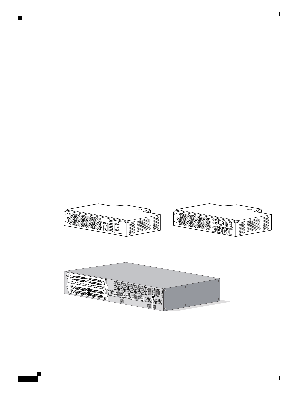
Figure 1 shows AC and DC power supplies for Cisco 3631 routers.
Figure 2 shows the location of the power supply in Cisco 3631 routers. The AC or DC power supply
occupies the same location in the router.
Figure 1 Cisco 3631 AC and DC Power Supplies
AC power supply
Figure 2 Power Supply Location in the Cisco 3631 Router
AIC-64
C
O
N
N
1
C
O
N
N
C
O
N
AS
YN
C
3
1
2
7
3
0
2
6
2
9
A
S
Y
N
C
2
5
2
2
8
2
4
1
5
1
1
1
4
1
0
1
3
A
S
Y
N
C
9
8
1
2
8
3
N
2
C
O
N
N
4
STAT
4
3
1
2
3
2
2
2
1
2
0
1
5
7
6
5
4
EN
1
9
1
8
A
S
Y
N
C
1
7
1
6
2
3
1
6
3
2
A
S
Y
N
1
C
0
7
0
TD
RD
LP
AL
CD
S
E
E M
A
N
U
A
L B
D
E
S
FO
U
R
E
INS
EN
TA
LLA
5
TIO
6
K
N
S
EE
M
A
N
U
A
L B
E
FO
R
E IN
S
TA
LLA
T
IO
N
DC power supply
62510
62468
Power supply
Power Requirements for the Cisco 3631 Router
The following power requirements apply to the Cisco 3631 router:
Installing Power Supplies in Cisco 3631 Routers
6
78-13818-03
Page 7
Accessing the Power Supply
To access power supplies on the Cisco 3631 router, remove the router cover as described in the “Removing
the Router Cover” section on page 8.
Replacing the Cisco 3631 Power Supply
Warning
Warning
Warning
Warning
Before working on a chassis or working near power supplies, unplug the power cord on AC units;
disconnect the power at the circuit breaker on DC units. To see translations of the warnings that
appear in this publication, refer to the Regulatory Compliance and Safety Information document
that accompanied this device.
Do not touch the power supply when the power cord is connected. For systems with a power
switch, line voltages are present within the power supply even when the power switch is off and
the power cord is connected. For systems without a power switch, line voltages are present within
the power supply when the power cord is connected. To see translations of the warnings that
appear in this publication, refer to the Regulatory Compliance and Safety Information document
that accompanied this device.
Do not work on the system or connect or disconnect cables during periods of lightning activity. To
see translations of the warnings that appear in this publication, refer to the Regulatory
Compliance and Safety Information document that accompanied this device.
Before opening the chassis, disconnect the telephone-network cables to avoid contact with
telephone-network voltages. To see translations of the warnings that appear in this publication,
refer to the Regulatory Compliance and Safety Information document that accompanied this
device.
Warning
Network hazardous voltages are present in the BRI cable. If you detach the BRI cable, detach the
end away from the router first to avoid possible electric shock. Network hazardous voltages also
are present on the system card in the area of the BRI port (RJ-45 connector), regardless of when
power is turned off. To see translations of the warnings that appear in this publication, refer to the
Regulatory Compliance and Safety Information document that accompanied this device.
Replacing the Cisco 3631 Power Supply
The power supply and cabling for the Cisco 3631 router is contained inside the chassis. To replace the
power supply, complete these procedures:
• Removing the Router Cover, page 8
• Removing the Cisco 3631 Power Supply, page 9
• Installing the Cisco 3631 Power Supply, page 14
• Replacing the Router Cover, page 14
Installing Power Supplies in Cisco 3631 Routers
78-13818-03
7
Page 8

Replacing the Cisco 3631 Power Supply
Removing the Router Cover
To gain access to the Cisco 3631 power supply, you must first remove the chassis cover:
Step 1 Turn off power to the router.
Step 2 Remove all network interface cables from the rear panel.
Step 3 If you have an AC-powered router, remove the power cord.
Step 4 The following warnings apply to routers with DC power supplies:
Warning
Warning
Before performing any of the following procedures, ensure that power is removed from the DC
circuit. To ensure that all power is OFF, locate the circuit breaker on the panel board that services
the DC circuit, switch the circuit breaker to the OFF position, and tape the switch handle of the
circuit breaker in the OFF position. To see translations of the warnings that appear in this
publication, refer to the Regulatory Compliance and Safety Information document that
accompanied this device.
When installing the unit, always make the ground connection first and disconnect it last. To see
translations of the warnings that appear in this publication, refer to the Regulatory Compliance
and Safety Information document that accompanied this device.
If you have a DC-powered router, follow these steps to remove the power cables:
a. Use a screwdriver to loosen the captive installation screws on the terminal block cover.
b. Lift and remove the terminal block cover.
c. Use a screwdriver to remove the three power leads from the terminal block, in this order: negative,
positive, then ground.
Step 5 Place the router so the rear panel is closest to you. Remove the five screws located on top of the cover.
Set the screws aside in a safe place.
Step 6 Lift the front edge of the cover. (See number 1 in Figure 3.)
Step 7 Slide the cover toward the right until the metal tabs on the rear edge separate from the chassis bottom.
(See number 2 in Figure 3.)
Installing Power Supplies in Cisco 3631 Routers
8
78-13818-03
Page 9

Figure 3 Removing the Cisco 3631 Cover
Replacing the Cisco 3631 Power Supply
2
1
Step 8
Lift the cover completely off and set it aside.
When you are ready to replace the cover, see the “Replacing the Router Cover” section on page 14.
Removing the Cisco 3631 Power Supply
After you remove the cover from the chassis, follow this procedure to remove the power supply:
Step 1 Find the Compact Flash memory card located on the side wall of the chassis. (See Figure 4.)
62483
78-13818-03
Installing Power Supplies in Cisco 3631 Routers
9
Page 10

Replacing the Cisco 3631 Power Supply
Figure 4 Compact Flash in a Cisco 3631 Router
Retention screw
Compact Flash
memory card
62479
Step 2
Remove the Compact Flash memory retention screw and set it aside. (See Figure 4.)
Step 3 Lift the Compact Flash memory card up and away from the Compact Flash receptacle and set it aside.
(See Figure 4.)
Step 4 Find the large power connector on the motherboard and remove it. (See Figure 5.)
Note On a Cisco 3631 router, you can simply lift the connector away from the receptacle. (See
Figure 5.)
10
Installing Power Supplies in Cisco 3631 Routers
78-13818-03
Page 11

Figure 5 Removing the Cisco 3631 Power Connector
Replacing the Cisco 3631 Power Supply
62511
Step 5 The Cisco 3631 power supply is held in the chassis by three external mounting screws at the rear of the
router. (See Figure 6.) Remove the screws and set them aside.
Figure 6 Cisco 3631 Power Supply Mounting Screws
Mounting
screws
Power
62512
supply
Step 6 Slide the power supply back slightly in the chassis. This disengages the hooks built into the chassis that
help secure the power supply. (See Figure 7 and Figure 8.)
78-13818-03
Installing Power Supplies in Cisco 3631 Routers
11
Page 12

Replacing the Cisco 3631 Power Supply
Figure 7 Cisco 3631 Power Supply Mounting Hinge (Right)
Hinge location
Power supply
latch
Locked position
Hinge
62569
12
Installing Power Supplies in Cisco 3631 Routers
78-13818-03
Page 13

Figure 8 Cisco 3631 Power Supply Mounting Hinge (Left)
Replacing the Cisco 3631 Power Supply
Hinge
62513
Step 7 Pull the power supply back and lift the power supply out of the chassis. (See Figure 9.)
78-13818-03
Installing Power Supplies in Cisco 3631 Routers
13
Page 14

Replacing the Cisco 3631 Power Supply
Figure 9 Cisco 3631 Power Supply Removal
62556
Installing the Cisco 3631 Power Supply
To install a power supply in the chassis, follow these steps:
Step 1 Place the power supply in the chassis, with the power supply rear panel slightly separated from the
chassis rear panel. This position allows the hooks in the chassis to engage the cutouts in the bottom of
the power supply. (See Figure 7 and Figure 8.)
Step 2 Slide the power supply toward the rear of the chassis, engaging the hooks in the chassis.
Step 3 Replace the external rear mounting screws. (See Figure 6.)
Step 4 Insert the large power connector into the receptacle on the motherboard. (See Figure 5.)
Step 5 Reinsert the Compact Flash memory card in the receptacle and screw in the Compact Flash memory
retention screw.
Replacing the Router Cover
After you finish replacing the power supply, follow these steps to replace the cover:
Step 1 Place the chassis bottom so the front panel is closest to you.
Step 2 Hold the cover so the tabs at the rear of the cover are aligned with the chassis bottom.
14
Installing Power Supplies in Cisco 3631 Routers
78-13818-03
Page 15

Electrical Connections for Cisco 3631 Routers
Step 3 Push the cover toward the rear, making sure that the cover tabs fit under the chassis back panel, and the
back panel tabs fit under the cover.
Step 4 Slide the cover slightly to the left to lock the cover into position (number 1 in Figure 10).
Figure 10 Replacing the Cisco 3631 Router Cover
1
2
Step 5
Step 6 Fasten the cover with the five screws you set aside earlier.
Step 7 Reinstall the chassis on a rack.
Step 8 Reinstall network interface cables.
Step 9 Proceed to the “Electrical Connections for Cisco 3631 Routers” section on page 15.
Lower the front of the cover onto the chassis (number 2 in Figure 10).
Electrical Connections for Cisco 3631 Routers
This section explains how to connect AC or DC power to Cisco 3631 routers.
62491
78-13818-03
Installing Power Supplies in Cisco 3631 Routers
15
Page 16
Electrical Connections for Cisco 3631 Routers
Warning
Warning
Warning
Caution If you connect parallel dual 48V DC power sources, both sources must be the same polarity. Do not
This unit is intended for installation in restricted access areas. A restricted access area is where
access can only be gained by service personnel through the use of a special tool, lock and key, or
other means of security, and is controlled by the authority responsible for the location. To see
translations of the warnings that appear in this publication, refer to the Regulatory Compliance
and Safety Information document that accompanied this device.
Before performing any of the following procedures, ensure that power is removed from the DC
circuit. To ensure that all power is OFF, locate the circuit breaker on the panel board that services
the DC circuit, switch the circuit breaker to the OFF position, and tape the switch handle of the
circuit breaker in the OFF position. To see translations of the warnings that appear in this
publication, refer to the Regulatory Compliance and Safety Information document that
accompanied this device.
This product relies on the building’s installation or power supply for short circuit (overcurrent)
protection. Ensure that a Listed and Certified fuse or circuit breaker no larger than 60 VDC, 15A is
used on all current-carrying conductors. To see translations of the warnings that appear in this
publication, refer to the Regulatory Compliance and Safety Information document that
accompanied this device.
connect –48V and +48V sources to a Cisco 3631 router. Opposite-polarity sources connected in
parallel will damage the power supply.
Note The installation must comply with the 2002 National Electric Code (NEC) and other applicable
codes.
Warning
This product is intended for use with copper conductors only.
Wire and Terminal Requirements
A Cisco 3631 router with a DC-input power supply requires copper wire, size AWG 18 (1.0 mm2), for
the power connections, and it requires a NEBS-compliant ground connection on the chassis, using size
AWG 6 (minimum 13 mm
The connections must be made using crimp-type ring terminals, Molex part number 19073-0009
(individual), 19073-0019 (on tape and reel), or equivalent.
You can connect a single DC power source to either the A input or the B input. If there are parallel dual
power sources, connect one source to the A input and one source to the B input; both sources must be
the same polarity (–48V or +48V). A NEBS-compliant chassis ground connection is required with both
single source and parallel dual sources.
2
) copper wire.
16
Installing Power Supplies in Cisco 3631 Routers
78-13818-03
Page 17
Wiring Procedure
Step 1 Strip the wires to the appropriate length for the ring terminals. The strip length is 1/8 to 3/16 inch (3 to
Step 2 Crimp the ring terminals to the DC power input wires.
Electrical Connections for Cisco 3631 Routers
To connect the router to a 48V DC power source, complete the following steps:
5 mm) for Molex number 19073-0009 terminals.
Warning
Step 3 Remove the plastic covers from the terminal block. Save them for reinstallation after you finish wiring.
Note Do not remove the colored screw at either end of the terminal block. Those are the terminal mounting
When stranded wiring is required, use approved wiring terminations, such as closed-loop or
spade-type with upturned lugs. These terminations should be the appropriate size for the wires
and should clamp both the insulation and conductor. To see translations of the warnings that
appear in this publication, refer to the Regulatory Compliance and Safety Information document
that accompanied this device.
screws.
Step 4 Connect the DC power input wires to the terminal block as shown in the applicable figure below. To
avoid interference with the on/off switches, and to bring the wires close to the cable-tie attachment
point, organize the wires downward from the terminal block.
Warning
This warning applies only to units equipped with DC input power supplies. Wire the DC power
supply using the appropriate lugs at the wiring end. The proper wiring sequence is ground to
ground, positive to positive (line to L), and negative to negative (neutral to N). Note that the ground
wire should always be connected first and disconnected last. To see translations of the warnings
that appear in this publication, refer to the Regulatory Compliance and Safety Information
document that accompanied this device.
Caution Do not overtorque the terminal block contact screws. The recommended torque is 8.2 ± 0.4 inch-lb.
Warning
An exposed wire lead from a DC-input power source can conduct harmful levels of electricity. Be
sure that no exposed portion of the DC-input power source wire extends from the terminal block
plug. To see translations of the warnings that appear in this publication, refer to the Regulatory
Compliance and Safety Information document that accompanied this device.
Wiring the DC-Input Power Supply for Cisco 3631 Routers
A Cisco 3631 router with a DC-input power supply requires copper wire and crimp-type ring terminals
for the power connections. Table 1 summarizes the wire size and ring terminal requirements.
78-13818-03
Installing Power Supplies in Cisco 3631 Routers
17
Page 18

Electrical Connections for Cisco 3631 Routers
Table 1 DC Wiring Requirements for Cisco 3631 Routers
Installed Power Supply DC Input Wire Size Ring Terminal (Lug) Overcurrent Protection
Nominal 48 VDC
Identification is stamped in
1
48 - 60V, 4A AWG 18 (1.0 mm2),
minimum
Molex part number
19193-0009, or equivalent
15A maximum
sheet metal near the DC wire
terminals:
INPUT -48 TO
-60V 4 A
1. The input voltage tolerance limits for nominal 48V power supplies are 38 and 72 VDC.
Figure 11 and Figure 12 show the router DC-input power supply terminal block.
Figure 11 DC Power Connections for -48V DC Input
Safety ground
Return, input A
Return, input B
-48V, input A
+
A
+
B
Figure 12 DC Power Connections for +48V DC Input
Safety ground
+48V, input A
Return, input A
+
A
+
B
Step 1 Install the plastic covers over the terminals.
Warning
The safety cover is an integral part of the product. Do not operate the unit without the safety cover
installed. Operating the unit without the cover in place will invalidate the safety approvals and
pose a risk of fire and electrical hazards. To see translations of the warnings that appear in this
publication, refer to the Regulatory Compliance and Safety Information document that
accompanied this device.
-48V, input B
Terminal strip
62557
+48V, input B
Return, input B
Terminal strip
62558
18
Installing Power Supplies in Cisco 3631 Routers
78-13818-03
Page 19
Electrical Connections for Cisco 3631 Routers
A
+
B
+
Warning
After wiring the DC power supply, remove the tape from the circuit breaker switch handle and
reinstate power by moving the handle of the circuit breaker to the ON position. To see translations
of the warnings that appear in this publication, refer to the Regulatory Compliance and Safety
Information document that accompanied this device.
Warning
Voltages might be present on the DC-input power supply terminals. Turn off the power source
circuit breaker and remove the power supply before accessing the terminals. To see translations
of the warnings that appear in this publication, refer to the Regulatory Compliance and Safety
Information document that accompanied this device.
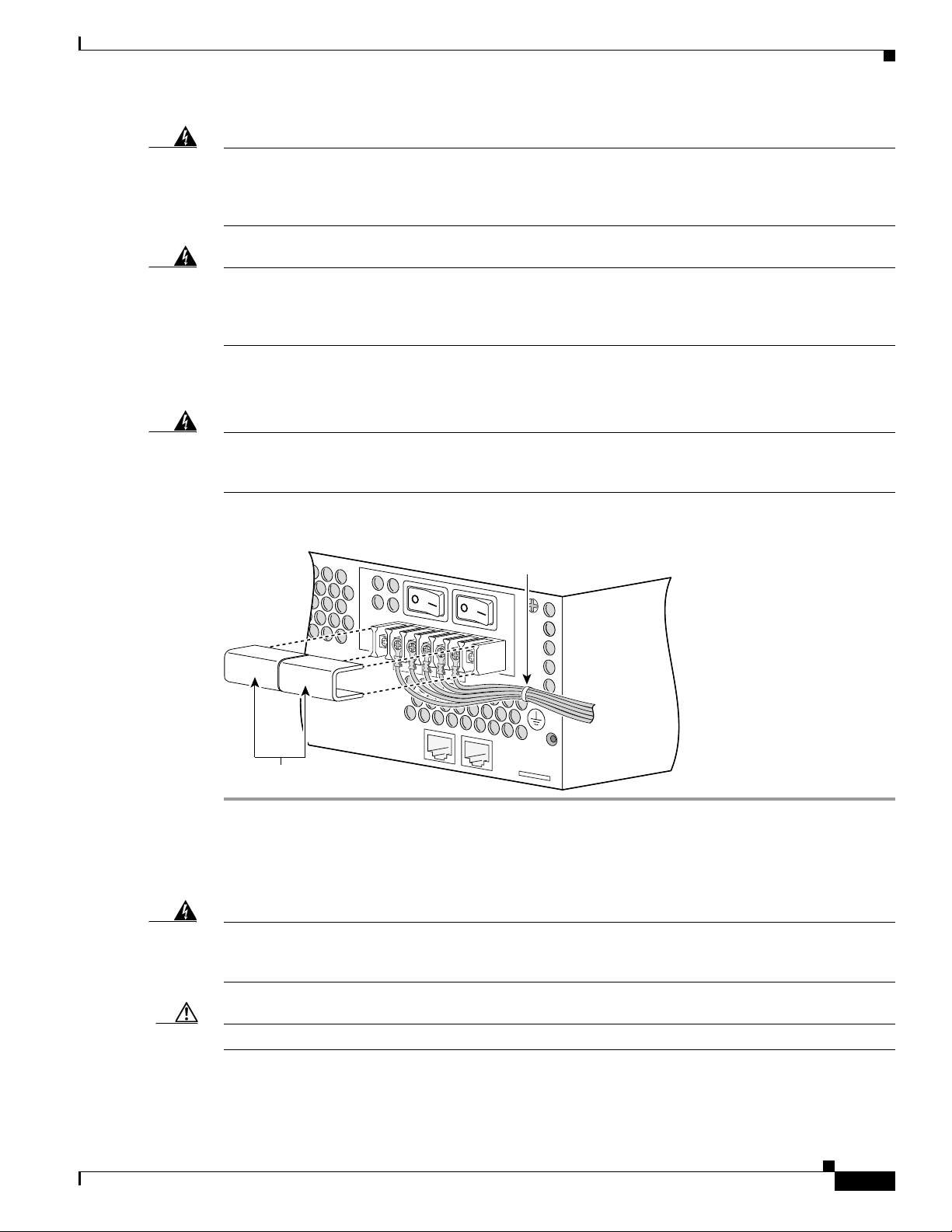
Step 2 Secure the wires using cable ties as shown below. The chassis has a cable-tie attachment below and to
the right of the terminal block.
Warning
Secure all power cabling when installing this unit to avoid disturbing field-wiring connections.
To see translations of the warnings that appear in this publication, refer to the Regulatory
Compliance and Safety Information document that accompanied this device.
Figure 13 Wire Routing and Attachment
Cable tie
Plastic covers
Powering On the Router
Warning
Caution Never operate the router unless the unit is completely closed, to ensure adequate cooling.
The plug-socket combination must be accessible at all times because it serves as the main
disconnecting device. To see translations of the warnings that appear in this publication, refer to
the Regulatory Compliance and Safety Information document that accompanied this device.
To power on the router, complete the following steps:
From DC
power
source
62471
Installing Power Supplies in Cisco 3631 Routers
78-13818-03
19
Page 20

Troubleshooting
Step 1 For routers with AC input, plug the router’s power cord into a three-terminal, single-phase power
source that provides power within the acceptable range.
Warning
Step 2 Power on the router. The LED labeled SYSTEM on the front panel should come on.
This product relies on the building’s installation or power supply for short circuit (overcurrent)
protection. Ensure that a Listed and Certified fuse or circuit breaker no larger than 60 VDC, 15A is
used on all current-carrying conductors. To see translations of the warnings that appear in this
publication, refer to the Regulatory Compliance and Safety Information document that
accompanied this device.
If you encounter problems when you power on the router, see the “Troubleshooting” section that follows.
Troubleshooting
Check the following items to help isolate problems with the power supply installation:
• With the power switch on, is the power LED on the front panel on?
–
–
–
• Does the router shut down after being on a short time?
–
–
–
If not, check the AC or DC input, AC or DC source, router circuit breaker, and the power supply
cable (AC) or power supply wiring (DC).
Check the power supply connection to the motherboard.
If the power LED is still off, the problem might be a power supply failure.
Check the fans. If the fans are not working, the router will overheat and shut itself down.
If the fans are not working, check the power supply connections to the fans.
Ensure that the chassis intake and exhaust vents are clear.
–
Check the environmental site requirements in your router installation and configuration guide.
Obtaining Documentation
The following sections explain how to obtain documentation from Cisco Systems.
World Wide Web
You can access the most current Cisco documentation on the World Wide Web at the following URL:
http://www.cisco.com
Translated documentation is available at the following URL:
http://www.cisco.com/public/countries_languages.shtml
Installing Power Supplies in Cisco 3631 Routers
20
78-13818-03
Page 21

Documentation CD-ROM
Cisco documentation and additional literature are available in a Cisco Documentation CD-ROM
package, which is shipped with your product. The Documentation CD-ROM is updated monthly and may
be more current than printed documentation. The CD-ROM package is available as a single unit or
through an annual subscription.
Ordering Documentation
Cisco documentation is available in the following ways:
• Registered Cisco Direct Customers can order Cisco product documentation from the Networking
Products MarketPlace:
http://www.cisco.com/cgi-bin/order_root.pl
• Registered Cisco.com users can order the Documentation CD-ROM through the online Subscription
Store:
http://www.cisco.com/go/subscription
• Nonregistered Cisco.com users can order documentation through a local account representative by
calling Cisco corporate headquarters (California, USA) at 408 526-7208 or, elsewhere in North
America, by calling 800 553-NETS (6387).
Obtaining Technical Assistance
Documentation Feedback
If you are reading Cisco product documentation on Cisco.com, you can submit technical comments
electronically. Click Leave Feedback at the bottom of the Cisco Documentation home page. After you
complete the form, print it out and fax it to Cisco at 408 527-0730.
You can e-mail your comments to bug-doc@cisco.com.
To submit your comments by mail, use the response card behind the front cover of your document, or
write to the following address:
Cisco Systems
Attn: Document Resource Connection
170 West Tasman Drive
San Jose, CA 95134-9883
We appreciate your comments.
Obtaining Technical Assistance
Cisco provides Cisco.com as a starting point for all technical assistance. Customers and partners can
obtain documentation, troubleshooting tips, and sample configurations from online tools by using the
Cisco Technical Assistance Center (TAC) Web Site. Cisco.com registered users have complete access to
the technical support resources on the Cisco TAC Web Site.
78-13818-03
Installing Power Supplies in Cisco 3631 Routers
21
Page 22

Obtaining Technical Assistance
Cisco.com
Cisco.com is the foundation of a suite of interactive, networked services that provides immediate, open
access to Cisco information, networking solutions, services, programs, and resources at any time, from
anywhere in the world.
Cisco.com is a highly integrated Internet application and a powerful, easy-to-use tool that provides a
broad range of features and services to help you to
• Streamline business processes and improve productivity
• Resolve technical issues with online support
• Download and test software packages
• Order Cisco learning materials and merchandise
• Register for online skill assessment, training, and certification programs
You can self-register on Cisco.com to obtain customized information and service. To access Cisco.com,
go to the following URL:
http://www.cisco.com
Technical Assistance Center
The Cisco TAC is available to all customers who need technical assistance with a Cisco product,
technology, or solution. Two types of support are available through the Cisco TAC: the Cisco TAC
Web Site and the Cisco TAC Escalation Center.
Inquiries to Cisco TAC are categorized according to the urgency of the issue:
• Priority level 4 (P4)—You need information or assistance concerning Cisco product capabilities,
product installation, or basic product configuration.
• Priority level 3 (P3)—Your network performance is degraded. Network functionality is noticeably
impaired, but most business operations continue.
• Priority level 2 (P2)—Your production network is severely degraded, affecting significant aspects
of business operations. No workaround is available.
• Priority level 1 (P1)—Your production network is down, and a critical impact to business operations
will occur if service is not restored quickly. No workaround is available.
Which Cisco TAC resource you choose is based on the priority of the problem and the conditions of
service contracts, when applicable.
Cisco TAC Web Site
The Cisco TAC Web Site allows you to resolve P3 and P4 issues yourself, saving both cost and time. The
site provides around-the-clock access to online tools, knowledge bases, and software. To access the
Cisco TAC Web Site, go to the following URL:
http://www.cisco.com/tac
All customers, partners, and resellers who have a valid Cisco services contract have complete access to
the technical support resources on the Cisco TAC Web Site. The Cisco TAC Web Site requires a
Cisco.com login ID and password. If you have a valid service contract but do not have a login ID or
password, go to the following URL to register:
22
http://www.cisco.com/register
Installing Power Supplies in Cisco 3631 Routers
78-13818-03
Page 23

If you cannot resolve your technical issues by using the Cisco TAC Web Site, and you are a Cisco.com
registered user, you can open a case online by using the TAC Case Open tool at the following URL:
http://www.cisco.com/tac/caseopen
If you have Internet access, it is recommended that you open P3 and P4 cases through the Cisco TAC
Web Site .
Cisco TAC Escalation Center
The Cisco TAC Escalation Center addresses issues that are classified as priority level 1 or priority
level 2; these classifications are assigned when severe network degradation significantly impacts
business operations. When you contact the TAC Escalation Center with a P1 or P2 problem, a Cisco TAC
engineer will automatically open a case.
To obtain a directory of toll-free Cisco TAC telephone numbers for your country, go to the following
URL:
http://www.cisco.com/warp/public/687/Directory/DirTAC.shtml
Before calling, please check with your network operations center to determine the level of Cisco support
services to which your company is entitled; for example, SMARTnet, SMARTnet Onsite, or Network
Supported Accounts (NSA). In addition, please have available your service agreement number and your
product serial number.
Obtaining Technical Assistance
78-13818-03
Installing Power Supplies in Cisco 3631 Routers
23
Page 24

Obtaining Technical Assistance
24
This document is to be used in conjunction with Cisco 3600 Series Hardware Installation Guide and the Regulatory Compliance and Safety
Information document for your router.
CCIP, the Cisco Arrow logo, the Cisco Po we red Network mark, the Cisco Systems Verified logo, Cisco Unity, Follow Me Browsing, FormShare, iQ
Breakthrough, iQ Expertise, iQ FastTrack, the iQ Logo, iQ Net Readiness Scorecard, Networking Academy, ScriptShare, SMARTnet, TransPath, and
Voice LAN are trademarks of Cisco Systems, Inc.; Changing the Way We Work, Live, Play, and Learn, Discover All That’s Possible, The Fastest Way
to Increase Your Internet Quotient, and iQuick Study are service marks of Cisco Systems, Inc.; and Aironet, ASIST, BPX, Catalyst, CCDA, CCDP,
CCIE, CCNA, CCNP, Cisco, the Cisco Certified Internetwork Expert logo, Cisco IOS, the Cisco IOS logo, Cisco Press, Cisco Systems, Cisco Systems
Capital, the Cisco Systems logo, Empowering the Internet Generation, Enterprise/Solver, EtherChannel, EtherSwitch, Fast Step, GigaStack, Internet
Quotient, IOS, IP/TV, LightStream, MGX, MICA, the Networkers logo, Network Registrar, Pack et , PIX, Post-Routing, Pre-Routing, RateMUX,
Registrar, SlideCast, StrataView Plus, Stratm, SwitchProbe, TeleRouter, and VCO are registered trademarks of Cisco Systems, Inc. and/or its affiliates
in the U.S. and certain other countries.
All other trademarks mentioned in this document or Web site are the property of their respective owners. The use of the word partner does not imply
a partnership relationship between Cisco and any other company. (0208R)
Copyright © 2002, Cisco Systems, Inc.
All rights reserved.
Installing Power Supplies in Cisco 3631 Routers
78-13818-03
 Loading...