

Page 1

Installation and Upgrade Guide for Cisco Unified Videoconferencing 3522 BRI Gateway and 3527 PRI Gateway Release 5.5
January 2008
Americas Headquarters
Cisco Systems, Inc.
170 West Tasman Drive
San Jose, CA 95134-1706
USA
http://www.cisco.com
Tel: 408 526-4000
800 553-NETS (6387)
Fax: 408 527-0883
Customer Order Number:
Text Part Number: OL-14910-01
Page 2

THE SPECIFICATIONS AND INFORMATION REGARDING THE PRODUCTS IN THIS M ANUAL ARE SUBJECT TO CHA NGE WITHOUT NO TICE. ALL
C
k
S
I
E
N
P
a
A
b
STATEMENTS, INFORMATION, AND RECOMMENDATIONS IN THIS MANUAL ARE BELIEVED TO BE ACCURATE BUT ARE PRESENTED WITHOUT
WARRANTY OF ANY KIND, EXPRESS OR IMPLIED. USERS MUST TAKE FULL RESPONSI BILITY FOR THEIR APPLICA TION OF ANY PRODUCT S.
THE SOFTWARE LICENSE AND LIMITED WARRANTY FOR THE ACCOMPANYING PRODUCT ARE SET FORT H IN THE INFORMATION PACKET T HAT
SHIPPED WITH THE PRODUCT AND ARE INCORPORATED HEREIN BY THIS REFERENCE. IF YOU ARE UNABLE TO LOCATE THE SOFTWARE LICENSE
OR LIMITED WARRANTY, CONTACT YOUR CISCO REPRESENTATIVE FOR A COPY.
The Cisco implementation of TCP head er compressi on is an adap tation of a program developed by the Universi ty of Ca lifornia, Berk eley (UCB) as part of UCB ’s public
domain version of the UNIX operatin g system. All rights reserved . Copyri ght © 1981 , Rege nts of the Uni versity of Calif ornia.
NOTWITHSTANDING ANY OTHER WARRANTY HEREIN, ALL DOCUMENT FILES AND SOFTWARE OF THE SE SUPPLIERS ARE PROVIDED “AS IS” WITH
ALL FAULTS. CISCO AND THE ABOVE-NAMED SUPPLIERS DISCLAI M ALL WARRANTIE S, EXPRESSED OR IMPLIED, INCLUDING, WITHOUT
LIMITATION, THOSE OF MERCHANTABILITY, FITNESS FOR A PARTICULAR PURPOSE AND NO NINFRINGEM ENT OR ARISING FROM A COURS E OF
DEALING, USAGE, OR TRADE PRACTICE.
IN NO EVENT SHALL CISCO OR ITS SUPPLIERS BE LIABLE FOR ANY INDIRECT, SPECIAL, CONSEQUENTIAL, OR INCIDENTAL DAMAGES, INCLUDING ,
WITHOUT LIMITATION, LOST PROFITS OR LOSS OR DAMAGE TO DATA ARISING OUT OF THE USE OR INABILITY TO USE THIS MANUAL, EVEN IF CISCO
OR ITS SUPPLIERS HAVE BEEN ADVISED OF THE POSSIBILITY OF SUCH DAMAGE S.
CSP, the Cisco Square Bridge logo, Follow Me Browsing, and StackWise are trademarks of Cisco Systems, Inc.; Changing the Way We Work, Live, Play, and Learn, and iQuic
tudy are service marks of Cisco Systems, Inc.; and Access Registrar, Aironet, ASIST, BPX, Catalyst, CCDA, CCDP, CCIE, CCIP, CCNA, CCNP, Cisco, the Cisco Certified
nternetwork Expert logo, Cisco IOS, Cisco Press, Cisco Systems, Cisco Systems Capital, the Cisco Systems logo, Cisco Unity, Empowering the Internet Generation,
nterprise/Solver, EtherChannel, EtherFast, EtherSwitch, Fast Step, FormShare, GigaDrive, GigaStack, HomeLink, Internet Quotient, IOS, IP/TV, iQ Expertise, the iQ logo, iQ
et Readiness Scorecard, LightStream, Linksys, MeetingPlace, MGX, the Networkers logo, Networking Academy, Network Registrar, Packet, PIX, Post-Routing, Pre-Routing,
roConnect, RateMUX, ScriptShare, SlideCast, SMARTnet, StrataView Plus, SwitchProbe, TeleRouter, The Fastest Way to Increase Your Internet Quotient, TransPath, and VCO
re registered trademarks of Cisco Systems, Inc. and/or its affiliates in the United States and certain other countries.
ll other trademarks mentioned in this document or Website are the property of their respective owners. The use of the word partner does not imply a partnership relationship
etween Cisco and any other company. (0501R)
Any Internet Protocol (IP) addresses used in this document are not intended to be actual addresses. Any examples, command display output, and figures included in the
document are shown for illustrative pur poses onl y. Any use of act ual IP addr ess es in ill ustr ativ e conten t is uninten tio nal and coincident al.
Installation and Upgrade Guide for Cisc o Unified Videoconferencing 3522 BRI Gateway and 3527 PRI Gateway Rel ease 5.5
© 2008 Cisco Systems, Inc. All rights res erved.
Page 3

CONTENTS
CHAPTER
1 Functionality 1-1
About Cisco Unified Videoconferencing 3500 Gateway Products 1-1
About the Cisco Unified Videoconferencing 3527 PRI Gateway 1-1
About the Cisco Unified Videoconferencing 3522 BRI Gateway 1-1
About Gateway Features 1-2
About Cisco Unified Videoconferencing 3500 Gateway Applications and Topologies 1-6
About Multimedia Conferencing 1-6
About Point-to-Point Conferencing 1-7
About Multipoint Conferencing 1-8
About Gateway IP Network Connections 1-8
About Gateway ISDN Network Connections 1-8
About Cisco Unified Videoconferencing 3500 Gateway Functionality 1-10
About PRI Gateway Call Handling Capacity 1-11
About BRI Gateway Call handling Capacity 1-11
About Gateway Call Bandwidth Overhead 1-11
Resource Allocation across E1/T1 Lines 1-12
About Peer-to-Peer Connectivity 1-12
CHAPTER
OL-14910-01
2 Setting Up Your Cisco Unified Videoconferencing 3500 Gateway 2-1
Physical Description 2-1
Front Panel 2-1
Cisco Unified Videoconferencing 3527 PRI Gateway Rear Panel 2-2
Cisco Unified Videoconferencing 3522 BRI Gateway RTM 2-3
Preparing for Installation of the Cisco Cisco Unified Videoconferencing 3527 PRI Gateway 2-3
Preparing for Installation of the Cisco Unified Videoconferencing 3522 BRI Gateway 2-4
Verifying the Package Contents 2-5
Mounting the Cisco Unified Videoconferencing 3500 Gateway Unit in a 19-inch Rack 2-5
Cisco Unified Videoconferencing 3500 Gateway Unit Initial Configuration 2-6
Connecting to a PC 2-7
Setting the IP Address 2-7
Changing the Configuration Tool Login Password 2-9
Connecting the Cisco Unified Videoconferencing 3500 Gateway Unit to the LAN 2-10
Managing and Monitoring the Cisco Unified Videoconferencing 3500 Gateway Unit 2-10
Installation and Upgrade Guide for Cisco UnifiedVideoconferencing 3522 BRI Gateway and 3527 PRI Gateway Release5.5
iii
Page 4

Contents
SNMP Management 2-10
Local Port Monitoring Connections 2-10
Performing Software Upgrades 2-11
Accessing the Cisco Unified Videoconferencing 3500 Gateway Administrator Interface 2-11
Registering the Online Help 2-12
Netscape Navigator Users 2-12
CHAPTER
CHAPTER
CHAPTER
CHAPTER
3 Using the Cisco Software Upgrade Utility 3-1
Introduction 3-1
Launching the Cisco Software Upgrade Utility 3-1
Upgrading Software 3-2
4 Cable Connections and Pin-outs 4-1
Unit RS-232 9-Pin Serial Port 4-1
RJ-45 8-Pin IP Network Port 4-2
ISDN Port 4-2
5 Technical Specifications 5-1
Technical Specifications Table 5-1
6 Safety 6-1
Electrical Safety 6-1
Grounding 6-1
High Voltage 6-2
iv
ESD Procedures 6-2
Sicherheit 6-3
Elektrische Sicherheit 6-3
Hochspannung 6-3
ESD-Verfahren 6-3
Warnhinweise 6-3
Seguridad 6-4
Seguridad Electrica 6-4
Puesta a Tierra 6-4
Alta Tensión 6-4
Fuente de Alimentación 6-4
Procedimientos ESD 6-5
Installation and Upgrade Guide for Cisco Unified Videoconferencing 3522BRI Gateway and 3527 PRI Gateway Release 5.5
OL-14910-01
Page 5

Securite 6-6
Securite Electrique 6-6
Mise a la Terre 6-6
Haute Tension 6-7
Prevention des Decharges Electrostatiques 6-7
Contents
CHAPTER
I
NDEX
7 Compliance and Certifications 7-1
Safety Compliance 7-1
EMC 7-2
FCC Part 15 Notice 7-2
Telecom 7-2
ACTA Part 68 Notice 7-3
Industry Canada 7-3
Environmental Compliance 7-4
OL-14910-01
Installation and Upgrade Guide for Cisco UnifiedVideoconferencing 3522 BRI Gateway and 3527 PRI Gateway Release5.5
v
Page 6

Contents
vi
Installation and Upgrade Guide for Cisco Unified Videoconferencing 3522BRI Gateway and 3527 PRI Gateway Release 5.5
OL-14910-01
Page 7

CHA PTER
1
Functionality
This section describes the following topics:
• About Cisco Unified Videoconferencing 3500 Gateway Products, p ag e 1-1
• About Gateway Features, page 1- 2
• About Cisco Unified Videoconferencin g 3 500 Gateway Applications an d Topologies, page 1-6
• About Cisco Unified Videoconferencing 3500 Gateway Functionalit y, page 1-10
About Cisco Unified Videoconferencing3500 Gateway Products
The Cisco Unified Videoconferenc ing 3500 Gateway series consi sts of t he foll owing pr oduct s:
• Cisco Unified Videoconferencing 3527 PRI Gateway (see the “About the Cisco Unified
Videoconferencing 3527 PRI Gateway”)
• Cisco Unified Videoconferencing 3522 BRI Gateway (see the “About the Cisco Uni fied
Videoconferencing 3522 BRI Gateway” section on page 1-1)
About the Cisco Unified Videoconferencing 3527 PRI Gateway
The Cisco Unified Videoconferencing 3527 PRI Gateway enables audio, video, and data communication
between H.320 endp oi nts that co nne ct thro ugh I SDN, and H .323 en dpoin ts tha t c onnec t t hr ough a
packet-based network. For voice-over-IP, the gateway enables PSTN voice callers to connect from the
ISDN network to I P voice cal ler s. The Cisco Unified Videoconferencing 3527 PRI Gateway suppo rts
one PRI ISDN port.
About the Cisco Unified Videoconferencing 3522 BRI Gateway
The Cisco Unified Videoconferencing 3522 BRI Gateway enables audio, video and data communication
between H.320 endpoints that connect through Integrated Services Digita l Network (ISDN), and H.323
endpoints that connect through a packet-based network. For voice-over-IP, the gateway enables Public
Switched Telephone Network (PSTN) voice callers to connect with IP voice callers. The Cisco Unified
Videoconferencing 3522 BRI Gateway supports up to four BRI ISDN ports.
OL-14910-01
Installation and Upgrade Guide for Cisco Unified Videoconferencing 3522BRI Gateway and 3527 PRI Gateway Release 5.5
1-1
Page 8

About Gateway F eatures
About Gateway Features
Table 1-1 lists the major feat ur es of t he Ci sco Unified Videoconferencing 3500 Gateway.
Table 1-1 Gateway Feature Summary
Feature Description
Interoperability The gateway provides a high degree of interoperability with other H.323
Web-based
management
SNMP management The gateway features Simple Network Manageme nt Protocol (SN MP)
Diagnostics The gateway features front and rear pan el LED indic ators that display
Network load
balancing
T.120 data
collaboration
Quality of service
(QoS)
Dial plan The gateway supports a simplified dial plan for out bound dia ling using a
Direct dialing and call
routing
Chapter1 Functionality
compliant gateways, gatekeepe rs, t erm in als, prox y, and Multipoint
Control Unit (M CU) p rod uct s by bei ng base d on t h e H .32 0 stand ar d and
H.323 protocol stac k.
The gateway features the gateway interface. This is a web interface used
to configure and monitor the gateway. You can view and modify all
aspects of th e gat eway configurati on f rom a r emot e l oca tio n u sing a
Java-enabled web browser.
management that su ppo rts a ll a spe cts of m onit oring, di agno stics,
configuration, and t rappi ng.
status for the unit. You can also access remote diagno stics of the unit
through the ga teway interfa ce, Telnet, SNMP, or a serial port.
The gateway supports load balancing on the networ k by communicati ng
with a gatekeeper throu gh H.32 3 RAI (Res ource Available
Indication)/RAC (Resource Available Confirmation) messages.
The gateway supports data transfers in calls between ISDN and IP by
using high speed T.120 in HMLP and VarMLP formats.
The gateway features c on figurabl e c oding o f m e dia packe ts t o achi eve
QoS routing priority on th e Intern et Protoco l (IP) netwo rk. The Type of
Service (ToS) bits of the IP datagr am head er can be conf igured f or pri ority
level.
single universal prefix. Using the dial plan, the gateway automatically
detects the capabilities recei ved in the Setup m essage from the IP endpoint
and sets the same bit ra te for th e ISDN (or seri al inte rf ace) side of the call .
The gateway dial plan supports the fo llowing direct dial ing and ca ll
routing facilities:
1-2
• Direct Inward Dialing (DID)
• Multiple Subscriber Network (MSN)
• Q.931 Sub-addressing Inf orm ation E lem en t
Internal and External Interactive Voice Response (IVR)
• TCS4
• Default extension
Access control The gateway features password-controlled access to the gateway interface.
Up to ten different administrator access profiles can be defined for the
gateway.
Installation and Upgrade Guide for Cisco Unified Videoconferencing 3522BRI Gateway and 3527 PRI Gateway Release 5.5
OL-14910-01
Page 9

Chapter 1 Functionality
About Gateway Features
Table 1-1 Gateway Feature Summary (continued)
Feature Description
DTMF translation The gateway supports translation between in-band Dual Tone
Multi-Frequency (DTM F) sig nal s (on th e ISD N si de) and out- of- band
H.245 messages (on the IP side). DTMF translation occurs for voice and
video calls.
Dual video The gateway sup ports H.239 standards-based d ual video and TANDBERG
DuoVideo technology. Dual video streams enable a screen to carry video
images from one sourc e while simul taneousl y displayi ng images fro m a
second source.
Conceal caller ID The gateway supports a conceal caller ID feature that instructs the
gatekeeper to conc eal the id entity of the call ing endp oint on th e IP or
ISDN network, whether the presentation restricted feature is enabled or
not.
H.323 fast start The gateway H.323 fast start feature enab les endpo ints to jo in a voice
conference in the gateway more quickly.
ISDN rollover
(available in
Cisco Unified
Videoconferencing 35
The gateway features ISDN rollover. In this feature, the gateway sends a
“busy out” channel request to the PSTN switch when th e curren t PRI
connection is left with less than a predefined number of available B
channels. The PSTN switch “rolls over” to the next available gateway.
27 PRI Gateway only)
Network Specific
Facility (available in
Cisco Unified
Videoconferencing 35
The gateway provides support for Network Specific Facility Information
Elements (NSF IEs) which enable system administrators to specify to
service providers the eq uipment, service, or ne twork throug h which they
want a call routed.
27 PRI Gateway only)
ISDN connectio n
failure
The gateway responds to ISDN connection failure events, by unregistering
from its gatekeeper. The gatekeeper is forced to send new IP-to-ISDN
calls through a different gateway, thus ensuring high call completion rates.
The gateway re-registers to the gatekeeper when the ISDN connection is
restored.
Downspeeding The gateway features downspeeding functionality. In the downspeeding
feature, the gateway attempts to reconnect a disconnected video call either
at a lower bandwidth or as a voice c a ll. D ownspeedi ng c ontr ibutes to a
higher percen tag e of c all c om pleti on o n the network. T he ga teway
supports downspeeding at call set up and in mid- call.
Multiple trap server
The gateway supports up to three SNMP trap servers.
support
H.239 support The gateway supports the H.239 protocol in ISDN-to-IP ca lls and in
IP-to-ISDN ca lls.
Encryption support The gateway supports H.235-compliant AES 128 encryption for calls over
IP networks, and H.233 and H.234 -comp liant AES 128 enc ryptio n for
calls over ISDN networks.
H.243 Conference
Control support
The gateway supports the H.243 protocol in ISDN-to- IP calls and in
IP-to-ISDN calls . T he ga teway iden tifies t he p roto col version t hat an I P
endpoint uses and sends H.239 capabilities only to those endpoints
working with protocol version 4.0 or later.
OL-14910-01
Installation and Upgrade Guide for Cisco Unified Videoconferencing 3522BRI Gateway and 3527 PRI Gateway Release 5.5
1-3
Page 10

About Gateway F eatures
Table 1-1 Gateway Feature Summary (continued)
Feature Description
Peer-to-peer
connectivity
The gateway supports connectivity to the IP network through a gatekeeper,
or directly to a peer device such as Cisco Unified Communications
Manager.
IP network
connections
The gateway has one 10/ 100B ase-T Ethern et IP port (on t he f ro nt p an el)
and connects to an IP segment through a direct connection to a network
switch.
Table 1-2 lists features for specific Cisco gateways.
Table 1-2 Cisco Gateway Feature Specifics
Chapter1 Functionality
Feature Cisco Unified
Videoconferencing 3527 PRI Gateway
Cisco Un ified
Videoconferencing 3522 BRI Gateway
Supported ports 1 PRI ISDN port 4 BRI ISDN ports
Supported video
H.320, H.323 (using Cisco Stack v4. 0)
conferencing pr otocols
Supported audio
codecs
The term audio transcoded video calls refers to the proc ess wh ereb y an audio
stream in a multimedia call can be transcoded from one codec type to another.
Basic and advanced a udio cod in g s uppo rte d cod ecs : G .711 , G.72 2, G.72 2. 1,
G.723.1, G.728
Audio Transcoding G.711 (ISDN) < > G.723.1 (IP) for up
to 30 voice ch an ne ls .
G.711 (IP) < > G.728 (ISDN) for up to
20 audio tran sco de d v ide o c hann el s.
G.711 (ISDN) < > G.723.1 (IP) for up
to 8 voice channels.
G.711 (IP) < > G.728 (ISDN) for up to
8 audio transcoded video ch annels .
The gateway automatically performs
A-Law G.711-to-µ-Law G.711
translation be twee n the IP and ISD N
sides if needed.
Note When your Cisco unit
includes both a gateway and a
MCU, G.728 transcodi n g is
supported on the MCU only.
Supported video
H.261, H.263, H.26 3+ (Annexes F, J and N), H.263++ (Annex W), H.264
protocols
Supported video
VGA, XGA, SVGA, SIF, 4SIF, CIF, QCIF, 4CIF, 16CIF
resolutions
Supported bandwidths
(Kbps)
56, 64, 112, 128 , 168, 1 92, 2 24, 2 56,
280, 320, 336, 384, 44 8, 51 2, 67 2,
56, 64, 112, 1 28, 2 24, 25 6, 33 6, 38 4
and 512
768, 1288, 1472, 1680 an d 1920
Note Bandwidth rates of 256 Kbp s a nd up suppor t t he G .722 a udio code c .
1-4
Installation and Upgrade Guide for Cisco Unified Videoconferencing 3522BRI Gateway and 3527 PRI Gateway Release 5.5
OL-14910-01
Page 11

Chapter 1 Functionality
About Gateway Features
Table 1-2 Cisco Gateway Feature Specifics (continued)
Feature Cisco Unified
Videoconferencing 3527 PRI Gateway
Call handling
capabilities
For 1 x PRI T1 line:
23 ports (voice)
23 ports 1B (v ide o a nd dat a)
11 ports 2B (v ide o a nd dat a)
3 ports 6B (video and data)
For 1 x PRI E1 line:
30 ports (voice)
30 ports 1B (v ide o a nd dat a)
Cisco Un ified
Videoconferencing3522 BRI Gateway
For 4 x BRI lines:
8 voice-only calls or 8 video calls or
any combination of the two:
1 call x 512 Kbps
1 call x 384 Kbps +
2 calls x 256 Kbps
4 calls x 128 Kbps
8 calls x 64 Kbps
15 ports 2B (v ide o a nd dat a)
5 ports 6B (video and data)
Line quality Supports line echo cancellation, H.323 Fast Start and DTMF detection for
voice and video calls.
IP network conne ction I10/100Base-T Ethernet I P U TP c onn ect ion (on the fro nt pane l).
Serial control port
(DB-9) connection
Supported signaling
protocols
RS-232 DTE 9-pin D-t ype conne ction on fron t panel for co nnection to a PC
terminal or an external modem.
5ESS and 4ESS, DMS100, National
ISDN, Euro-ISDN, VN6 Dialing
(France), NTT (Japan), Hong Kong
Dialing (Hong Kong), Su ppo rt f or
Taiwan PRI system.
DMS100, National IS DN, 5 ESS
Custom/Multipoint (US, Taiwan)
5ESS PTP (US, Taiwan)
ETSI (France, E urope, Taiwan, Hong
Kong)
PRI interface Configurable E1/T1 PRI network
interface.
Support for frac ti onal E1/ T1 c han nel
selection.
Configurable as te rmin al sid e (T E) or
network side (NT) device.
Configurable Long Haul PRI module
(supported in Japan only ).
Switch information Numbering Plan Identifier (NPI),
Type of Number (TON) and Network
Specific Facility (NSF) information
elements are configurable per PRI
port.
ETSI PTP (France, Europe, Taiwan)
VN6 Dialing (Franc e)
Austel 1 Dialing (Austr alia)
KDD, NTT (Japan)
Hong Kong Dialing (Hong Kong).
N/A
N/A
OL-14910-01
Installation and Upgrade Guide for Cisco Unified Videoconferencing 3522BRI Gateway and 3527 PRI Gateway Release 5.5
1-5
Page 12

About Cisco Unified Videoconferencing 3500 Gateway Applications and Topologies
Table 1-2 Cisco Gateway Feature Specifics (continued)
Chapter1 Functionality
Feature Cisco Unified
Videoconferencing 3527 PRI Gateway
Bonding calls Internal Imux p rovidin g ca lls at 12 8
Kbps (2B) up t o ful l P RI of
1472 Kbps (23B ) for T 1 and up to fu ll
PRI of 1920 Kbps (30B) for E1 using
bonding mode 1.
Parallel dialing for bonded calls. Parallel dialing for bonded calls.
Internal IVR capacity 30 simultaneous calls 8 simultaneous calls
Cisco Un ified
Videoconferencing 3522 BRI Gateway
Internal Imux providing calls at 128
Kbps (2B) up to 512 Kbps (8B) using
bonding mode 1.
About Cisco Unified Videoconferencing3500Gateway
Applications and Topologies
The Cisco Unified Videoconferencing 3500 Gateway supports multimedia conferencing by translating
between H.323 and H .320 pro toco ls. Exa m ples of networ k ap plic atio ns t hat use t he ga teway inclu de :
• Multimedia conferencing (see the “About Multimedia Conferencing” section on page 1-6)
• Point-to-Point conferencing (see the “Ab out Poi nt-t o- Point C onfer en ci ng” se cti on on page 1-7)
• Multipoint conferencing (see the “About Multipoint Conferencing” section on page 1-8)
• IP networking (see the “About Gateway IP Network Connections” section on pa ge 1 -8)
• ISDN networking (see the “About Gateway ISDN Network Co nnecti on s” sect ion on page 1-8)
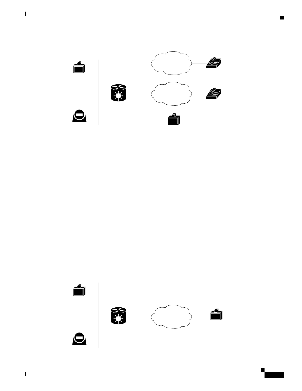
About Multimedia Conferencing
The Cisco PRI gat eway and BRI gat eway enabl e H .3 23 en dpo int s o n the IP n etwork t o com mu nica te
with an H.320 terminal, an ISDN phone, or a regular phone on a circuit-switched public network without
having to connect directly to these networks. The gateway allows all IP network terminals to support
video conference s w ithou t c onne ct ing every desktop c om pute r to an ISD N li ne ( see Figure 1-1).
1-6
Installation and Upgrade Guide for Cisco Unified Videoconferencing 3522BRI Gateway and 3527 PRI Gateway Release 5.5
OL-14910-01
Page 13
Chapter 1 Functionality
H.323
e
ar
e
157175
t
e
About Cisco Unified Videoconferencing 3500 Gateway Applications and Topologies
Figure 1-1 Multimedia Conferencing through th e Gateway
ndpoint
PSDN
ISDN
H.323
terminal
H.323
ndpoint
IP network
Cisco
chassis/unit
with serial
gateway
Typical multimedia conferencing applications include:
• Business video conferencing
• Distance learning
• Telemedicine
• Video-enabled call centers
• Telecommuting
Regul
phone
ISDN
phone
157174
About Point-to-Point Conferencing
The Cisco BRI gateway enables direct video, voice, and data communication between an H.320 (ISDN)
terminal and H.323 (IP) terminals at bandwidths of up to 512 Kbps (4 BRI lines) using bonding mode 1
(see Figure 1-2).
The Cisco PRI gateway enables direct video, voice, and data communication between an H.320 (ISDN)
terminal and H.323 (IP) term inals at ba ndwidths of up to 1472 Kbps (23 B bond ing for T1) and up t o
1920 Kbps (30B b ondin g f or E1).
Figure 1-2 Point-to -Point Confe rencing through the Gat eway
H.323
erminal
IP network
H.323
ndpoint
Cisco
chassis/unit
with serial
gateway
ISDN
H.323
terminal
OL-14910-01
Installation and Upgrade Guide for Cisco Unified Videoconferencing 3522BRI Gateway and 3527 PRI Gateway Release 5.5
1-7
Page 14
About Cisco Unified Videoconferencing 3500 Gateway Applications and Topologies
T
92871
T
T
T
T
IP
About Multipoint Conferencing
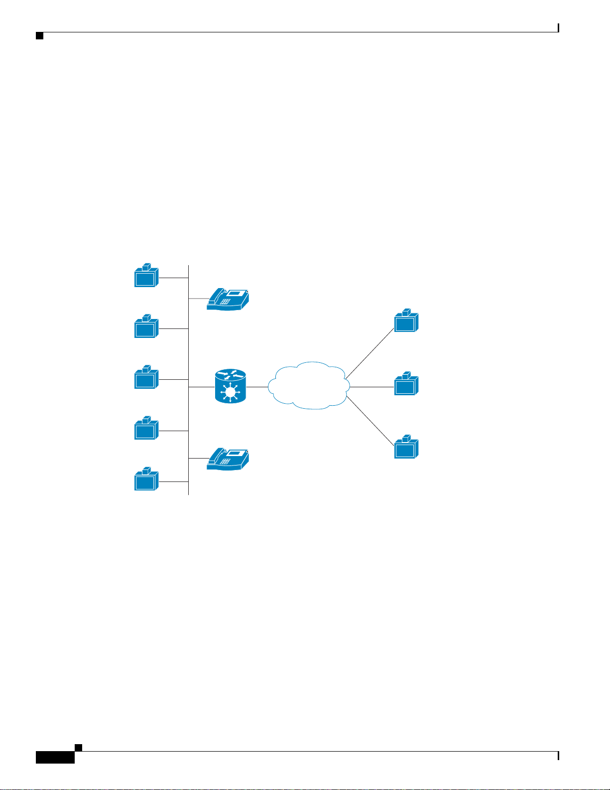
Together with the Cisco MCU, the Cisco PRI gateway and BRI gateway enable H.320 ISDN terminals
to participate in a mixed ISDN-IP mul tipoin t multim edia con ference w ith IP network end points (se e
Figure 1-3).
For example, when an H.320 ISDN terminal wants to participate in a multipoint conference with H.323
IP endpoints, the H.320 ISDN terminal can either join the multipoint conference by dialing to the
gateway, or be invited into the con fe renc e by one of th e pa rti ci pati ng IP endp oi nts. In ei ther c as e, t he
gateway connects the ISDN terminal to the Cisco MCU, enabling it to participate in the multipoint
conference.
Figure 1-3 Mixed ISDN-IP Multipoint Multimedia Conference
network
Chapter1 Functionality
H.323
erminal
H.323
erminal
H.323
erminal
Cisco IPVC MCU
H.323
erminal
H.323
erminal
IP
IP phone
Cisco IPVC
chassis/unit
Cisco IPVC
Gateway
IP
IP phone
H.320
Terminal
ISDN
H.320
Terminal
H.320
Terminal
About Gateway IP Network Connections
The Cisco PRI gateway and BRI gateway feature one 10/100Base-T Ethernet IP port (on the front panel)
and connect to an IP segment throug h a direct co nnec tion to a networ k switch.
About Gateway ISDN Network Connections
The Cisco BRI gateway feat ures four B RI ISD N c onn ect ions. Ea ch BRI l ine p rovides two B c hanne ls
and one D signalling channel.
Installation and Upgrade Guide for Cisco Unified Videoconferencing 3522BRI Gateway and 3527 PRI Gateway Release 5.5
1-8
OL-14910-01
Page 15
Chapter 1 Functionality
e
157167
H
e
PRI Gateways
About Cisco Unified Videoconferencing 3500 Gateway Applications and Topologies
The Cisco PRI gateway features configurable E1/T1 PRI ISDN connections. When configured as an E1
connection, each port provides 30 B channels and one D signaling channel. When configured as a T1
connection, each port provides 23 B channels and one D signaling channel. The type of line available
depends on your loc al ISDN provide r. You configure the gateway PRI po rt t o an E1 or T1 i n terface
accordingly. In addition, you can choose to activate only specific channels by using fracti onal channe l
selection.
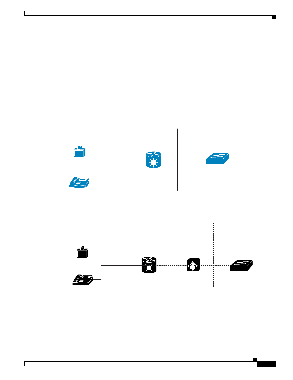
You can connect the PRI gateway directly to a PRI line pro vid ed b y your l ocal ISDN pro vider (as sho wn
in Figure 1-4), or to a local private branch excha nge (PBX) that provides th e PRI connection (as shown
in Figure 1-5).
Figure 1-4 Connecting the PRI Gateway Directly to a Central Office Switch
Private
IP
network
H.323
Terminal
IP
IP phone
Figure 1-5 Connecting the PRI Gateway to a PBX that Provides a PRI Line
.323 terminal
IP network
Cisco IPVC
chassis/unit
Cisco IPVC
Gateway
Cisco chassis/unit
PRI T1/E1
Public
PRI T1/E1
Central offic
switch
PublicPrivate
92873
Central Offic
switch
IP phone
Cisco Gateway
IP
Installation and Upgrade Guide for Cisco Unified Videoconferencing 3522BRI Gateway and 3527 PRI Gateway Release 5.5
OL-14910-01
PBX
1-9
Page 16
About Cisco Unified Video conferencing 3500 Ga te way Functionality
H
e
PublicPrivate
157165
H
PublicPrivate
e
BRI Gateways
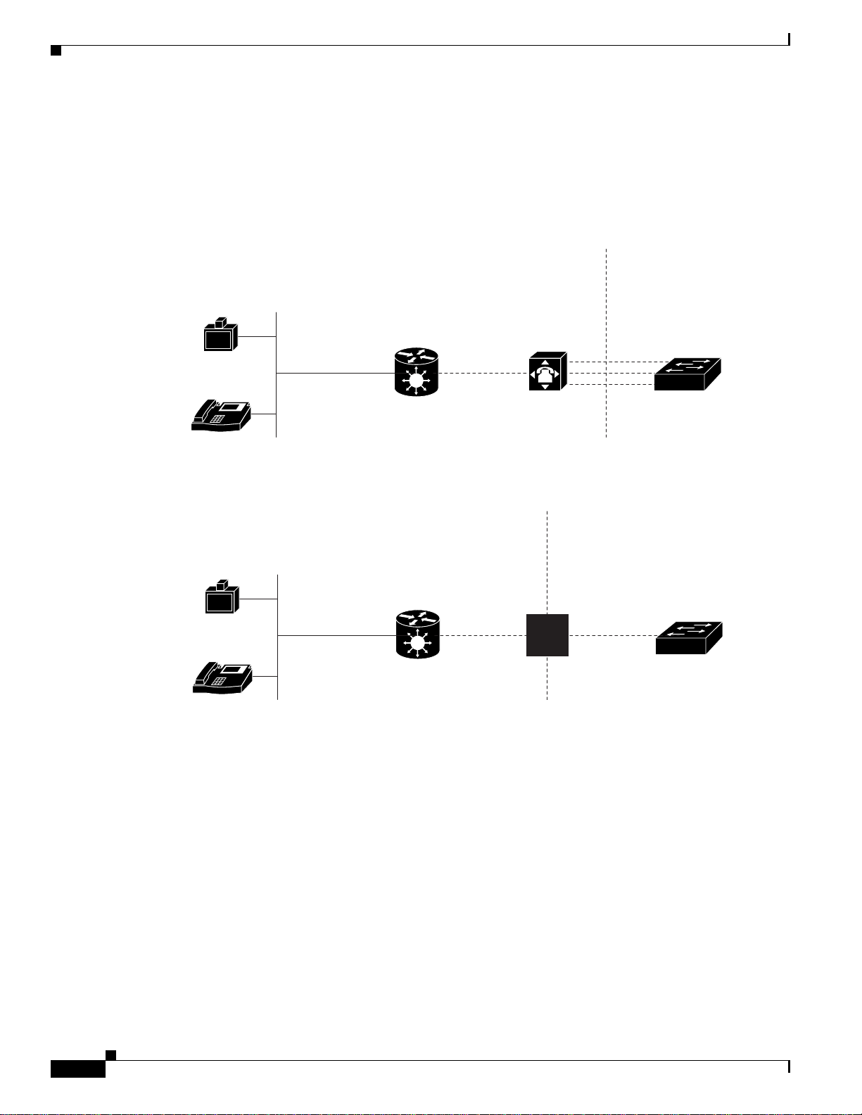
You can connect the BRI gateway to a local private branch exchange (PBX) that provides the BRI
connection (as shown i n Figure 1-6), or to a pu bli c ph one n etwor k using an NT 1 d evice (as shown i n
Figure 1-7).
Figure 1-6 Connecting the BRI Gateway Directly to a PBX that Provides a BRI Line
.323 terminal
IP network
Cisco chassis/unit
Chapter1 Functionality
Central Offic
switch
BRI
IP phone
Cisco Gateway
IP
Figure 1-7 Connecting the BRI Gateway Directly to a Central Office Switch
.323 terminal
IP network
Cisco chassis/unit
IP phone
Cisco Gateway
IP
PBX
NT1
device
Central Offic
switch
BRI
About Cisco Unified Videoconferencing3500Gateway
157166
Functionality
This section discusses the following topics:
• About PRI Gateway Call Handli ng Ca paci ty, page 1-11
• About BRI Gateway Call han dling Ca paci ty, page 1-11
• About Gateway Call Bandwid th Overhea d, page 1-11
• About Peer-to-Peer Connectivity, page 1-12
Installation and Upgrade Guide for Cisco Unified Videoconferencing 3522BRI Gateway and 3527 PRI Gateway Release 5.5
1-10
OL-14910-01
Page 17
Chapter 1 Functionality
About PRI Gateway Call Handling Capacity
Table 1-3 lists the maximum call handling capacity of the PRI gateway for different types of calls.
Table 1-3 PRI Gateway Call Handling Capacity
About Cisco Unified Videoconferencing 3500 Gateway Functionality
Call Type Maximum Number of
Calls Using 1 x E1 PRI
Line
voice (64 Kbps) 30 23
2B video (128 K bp s) 15 11
6B video (384 K bp s) 5 3
12B video (768 Kbps) 2 1
Note Enabling ISDN- to-I P D TMF de tect ion in t he PRI ga teway fo r vi deo c alls re duc es t he num be r of
supported calls by ha lf.
About BRI Gateway Call handling Capacity
Table 1-4 lists the maximum call ha ndli ng cap acit y of t he BRI gat eway for four BR I lines, ei ght
voice-only calls, or eight video calls, or any combination of the two.
Table 1-4 BRI Gateway Call Handling Capacity
Number of Calls Capacity
1 384 Kbps+ or 412 Kbps
2 256 Kbps
4 128 Kbps
864 Kbps
Maximum Number of
Calls Using 1 X T1 PRI
Line
About Gateway Call Bandwidth Overhead
According to the H.320 standard, the available bandwidth allocated to a call at any given bit rate will
always be slightly less than the stated maximum for the following reasons:
• All stated maxi mu m ca ll band widt h s inc lude p rovisio n f or cont ro l, audi o, vide o, a nd dat a t raffic.
• Video traffic on the ISDN side contains additional bits for error correction purposes which also
consume bandwid th. Video traffic on the IP side doe s n ot inc lude this addi tiona l l o ad.
• Opening an audio channel further reduces the bandwidth available to the video traffic.
For example, a call at 384 Kbps actually has onl y 363 Kbps available to it. Control and error correction
account for the rema ining 21 Kbps.
Installation and Upgrade Guide for Cisco Unified Videoconferencing 3522BRI Gateway and 3527 PRI Gateway Release 5.5
OL-14910-01
1-11
Page 18

About Cisco Unified Video conferencing 3500 Ga te way Functionality
Resource Allocation across E1/T1 Lines
The gateway can allocate bandwidth resources to calls across separate E1 or T1 connections to maximize
bandwidth capacity in cases where there is not enough capacity for a call on a single E1 or T1
connection, but where sufficient capacity does exist when remaining capacity on both E1/T1 lines is
combined.
For example, a gateway using two T1 li nes c an su pport thr ee 6B cal ls on e a ch T 1 li ne, wi th 32 0 Kb ps
spare capacity per line:
• Each T1 line provides 23 B channels.
• Each B channel su pport s 6 4 Kb ps
• Each T1 line supports 23 x 64 = 1472 Kbps
• Each 6B call requires 6 x 64 = 384 Kbps
• Each T1 line sup por ts 14 72/38 4 = 3 6B c a lls + 32 0 Kb ps s par e
The gateway processes an additional 6B call requiring a further 384 Kbps by taking bandwidth resources
from each of the two T1 lin es, both of which have 320 Kbps available. In this way, the gateway spreads
the call over both T1 lines.
Chapter1 Functionality
About Peer-to-Peer Connectivity
The gateway supports the following types of conne ctivity to the IP netwo rk
• Through a gatekeeper
• Directly to a peer device such as Cisco Unified Communications Manager without the need for a
gatekeeper.
1-12
Installation and Upgrade Guide for Cisco Unified Videoconferencing 3522BRI Gateway and 3527 PRI Gateway Release 5.5
OL-14910-01
Page 19

CHA PTER
157264
2
Setting Up Your Cisco Unified Videoconferencing 3500 Gateway
This section describes the following topics:
• Physical Description, page 2-1
• Preparing for Installation of the Cisco Cisco Unified Videoconferencing 3527 PRI Gateway,
page 2-3
• Preparing for Ins tal lati on of t he C i sco Unified Videoconferencing 35 22 BRI Gateway, page 2-4
• Ve rifying t he Package Conte nts, page 2-5
• Mounting the C isco Unified Videoconferencing 35 00 Gateway Unit in a 19 -inc h Rack , pag e 2-5
• Cisco Unified Videoconferencing 3500 Gateway Unit Initial Configuration, page 2-6
• Connecting the Cisco Unified Videoconferencing 3500 Gateway Unit to the LAN, page 2-10
• Managing and Monit ori ng the Ci sco Unified Videoconferencing 3500 G at eway Unit, pag e 2-10
• Accessing the Cisco Un ified Videoconferencing 3500 Gateway Administrator Interface, page 2-11
• Registering the Online Help, page 2-12
Physical Description
This section provides a physical descript ion of the Cisc o Un ified Videoconferencing 350 0 Gateway
units.
Front Panel
Figure 2-1 shows the front panel of the Cisco Unified Videoconferencing 3500 Gateway unit. Table 2-1
describes the com po nen ts of t he fro nt p an el.
Figure 2-1 Cisco Unified Videoconferencing 3500 Gateway Front Panel
10/100 Base T
SERIAL
CDGK Reg
RST
ACTALARM
PWR
OL-14910-01
Installation and Upgrade Guide for Cisco Unified Videoconferencing 3522BRI Gateway and 3527 PRI Gateway Release 5.5
2-1
Page 20
Physical Descriptio n
1
Chapter 2 Setting Up Your Cisco Unified Videoconferencing 3500 Gateway
Table 2-1 Front Panel Components
Component Description
10/100 BaseT conne ctor An RJ-45 connecto r that pro vides th e primary E thern et connect ion for the IP
network port.
SERIAL connector A DB-9 connector that allows you to connect a PC terminal for local
configuration.
RST button Allows you to reset the Cisco Unified Videoconferencing 3500 Gateway unit
manually.
GK Reg LED Lights green when the Cisco Unified Videoconferencing 3500 Gateway unit
is registered w it h a gate keep er.
CD LED Lights green when a PRI or BRI li ne i s en abl ed an d a ca rr ier si gn al i s
detected
ACT LED Lights green to indicate that there are active calls in the Cisco Unified
Videoconferencing 3500 Ga teway unit.
ALARM LED Lights green to indica te tha t an error has occ urred and the Ci sco U nified
Videoconferencing 3500 Ga teway unit r equi res re sett ing.
10/100 BaseT L EDs The top p art of the 10/ 10 0 B aseT conn ec tor cont ai ns two LED in dica tors .
The left-hand LED lights green when the local IP network link is active. The
right-hand LE D lights green if the connection speed is 100 Mbps, and is off
when the connection speed is 10 Mbps.
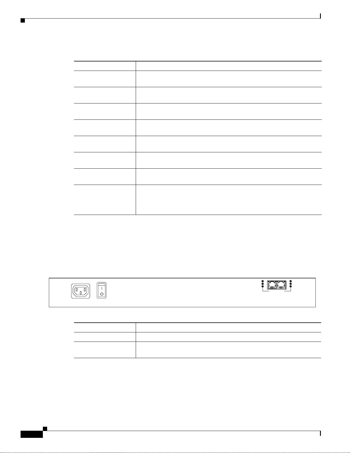
Cisco Unified Videoconferencing 3527 PRI Gateway Rear Panel
Figure 2-2 shows the rear panel components of the Cisco Unified Videoconferencing 3527 PRI Gateway
unit. Table 2-2 describes these components.
Figure 2-2 Cisco Unified Videoconferencing 3527 PRI Gateway: Rear Panel
ACT
D-Ch
ALARM
Table 2-2 Cisco Unified Videoconferencing 3527 PRI Gateway Rear Panel Components
Component Description
ACT LED Lights green to indicate that there are active calls in the gateway.
D-Ch LED Lights green to indicate that the PRI line is enabled and a carrier signal is
detected.
ACT
D-Ch
ALARM
PORT-1PORT-2
57266
2-2
Installation and Upgrade Guide for Cisco Unified Videoconferencing 3522BRI Gateway and 3527 PRI Gateway Release 5.5
OL-14910-01
Page 21
Chapter 2 Setting Up Your Cisc o Unified Videoconferencing 3500 Gateway
157262
Preparing for Installation of the Cisco CiscoUnified Videoconferencing 3527 PRI Gateway
Table 2-2 Cisco Unified Videoconferencing 3527 PRI Gateway Rear Panel Components
Component Description
ALARM LED Displays alarm events for the PRI line.
• YELLOW —Lights yellow when there is a loss of frame alignment at
the remote sid e.
• ORANGE—Lights orange when there is a loss of frame alignme nt in the
gateway.
PRI LINE connector RJ-45 connec tor tha t pro vides the PRI li ne con nection f or th e gate wa y ISDN
PRI port.
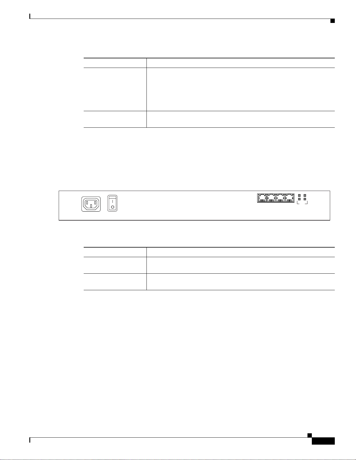
Cisco Unified Videoconferencing 3522 BRI Gateway RTM
Figure 2-3 shows the rear panel components of the Cisco Unified V ideoconferencing 3522 BRI Gateway
unit. Table 2-3 describes these components.
Figure 2-3 Cisco Unified Videoconferencing 3522 BRI Gateway: Rear Panel
Table 2-3 Cisco Unified Videoconferencing 3522 BRI Gateway Rear Panel Components
Component Description
ACT LEDs Lights green to indicate that there are active calls in the gateway on the
specified BRI line.
BRI LINE connectors RJ-45 connectors that provide the BRI line connections for the specified
gateway ISDN BRI port.
Preparing for Installation of the Cisco Cisco Unified
Videoconferencing3527 PRI Gateway
This section describes the requirements for installing the Cisco U nified
Videoconferencing 3527 PRI Gateway unit.
• Proper clearance at the sides of the unit to allow adequate ventilation, and at least 20 cm clearance
at the back of the unit to allow access to cable connections
2
1
43
ACT
BRI-1
BRI-2BRI-3BRI-4
OL-14910-01
• A PC with a serial port and terminal emulation software to assign the Cisco Unified
Videoconferencing 3527 PRI Gateway unit an IP address
• Dedicated IP address for the Cisco Unified Videoconferencing 3527 PRI Gateway unit
• The IP address of th e router that the Cisco Unified Videoconferencing 35 27 PRI Gateway unit will
use to communicate across the network
Installation and Upgrade Guide for Cisco Unified Videoconferencing 3522BRI Gateway and 3527 PRI Gateway Release 5.5
2-3
Page 22

Chapter 2 Setting Up Your Cisco Unified Videoconferencing 3500 Gateway
Preparing for Installation of the Cisco Unified Videocon ferencing 3522 BRI Gateway
• For an H.323 environment, the IP addr ess of t he H. 323 gat ekeepe r w ith whi ch y ou want the
Cisco Unified Videoconferencing 3527 PRI Gateway unit to register
• Available IP network ports on the switc h for the Cisco Unified
Videoconferencing 3527 PRI Gateway unit
• A grounded AC power outlet
• A 10BaseT or 100B ase T L AN ca ble
• Ambient room te mp er atu re rang e of 32
• Non-condensing r ela tive humidity rang e of 5% to 90%
o
to 104oF (0o to 40oC)
Preparing for Installation of the Cisco Unified
Videoconferencing3522 BRI Gateway
The Cisco Unified Videoconferencing 3 522 BRI Gateway prepares the signal ing for out bound
videoconference calls that are transmitted over Integrated Services Digital Network (ISDN) networks.
For videoconference in format ion to arr ive at its destination , you must work with the BRI ser vice
provider to ensure that the gateway and the ISDN service are compatible. You must gather information
about the service provider equipment and provide the service provider with information about the
gateway.
Before you order BRI se rv ice o r c onn ect the Cisc o Unified Videoconferencing 3522 B RI Gateway to
your existing BRI service, we suggest that you gather the following information.
Step 1 Ident if y the ISDN provide r you wa nt t o use as your Loc al E xcha nge C ar rier ( LEC) fo r loca l c a lls.
Note The LEC is the loc al telephone co mpan y that prov ides ISDN se rvices for your local ca lling are a
and to which your equipme nt con nects.
Step 2 Ident ify the ISDN provider you want to use as your Interexchange Carrier (IEC) for long-distance calls.
Note The IEC and the LEC are different companies. Often the LEC will contact the IEC and provision
long-distance service for you. V erify that your LEC performs this task, and contact an IEC if the
LEC does not.
Step 3 Determine how many BRI lines you want to connect to the gateway.
Step 4 Identi f y the ISD N e quipm e nt or sig na ling form a t you r LEC u ses .
Step 5 Dete rmin e whe ther y ou wan t to use la yer 1 l ine h unti ng.
Step 6 Have your ISDN service provider turn off the following switch settings:
• Packet Mode Data on the D channel
• Terminal Display Text
2-4
• EKTS
• Call Appearances
Installation and Upgrade Guide for Cisco Unified Videoconferencing 3522BRI Gateway and 3527 PRI Gateway Release 5.5
OL-14910-01
Page 23

Chapter 2 Setting Up Your Cisc o Unified Videoconferencing 3500 Gateway
• Key Hol d
• ACO
Verifying the Package Contents
Inspect the contents of the box for shipping damage. Report any damage or missing items to your Cisco
representative. Table 2-4 li sts the pack age co nten ts for th e Cis co Unified
Videoconferencing 3500 Gateway unit.
Table 2-4 Package Contents with Cisco Unified Videoconferencing3500 Gateway Unit
Product Contents
Cisco Unified Videoconferencing
3527 PRI Ga teway or Cisco Unified
Videoconferencing 3522 BRI Gateway unit
Verifying the Package Contents
• Cisco Unified Videoconferencing 3500 Gateway
Unit
• Guide to Cisco Conf ere ncin g D o cume ntat ion
• Regulatory Compliance an d Safety In forma tion for
Cisco Unified Videoconferencing 3500 Products
• Cisco Unified Videoconferencing Software
CD-ROM
• Cisco Information Packag e
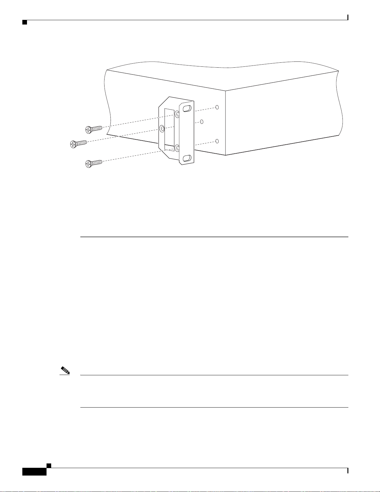
Mounting the Cisco Unified Videoconferencing3500Gateway Unit in a 19-inch Rack
Yo u can opti onall y mount the Cisco Unified Videoconferencing 3500 Gateway unit in a standard
19-inch rack. Two mounting brackets an d a set of sc rews are inc lude d in the Cisco Unified
Videoconferencing 3500 Gateway unit shipping box.
Procedure
Step 1 Disconnect all cables including the power cables.
Step 2 Place the Cisco Unified Videoconferencing 3500 Gateway unit right-side up on a hard flat surface, with
the front panel fac ing you .
Step 3 Position a mo unti ng br ac ket over the m oun ting hol es on e ach side o f th e Cisc o U n ified
Videoconferencing 3500 Gateway unit, as shown in Figure 2-4.
OL-14910-01
Installation and Upgrade Guide for Cisco Unified Videoconferencing 3522BRI Gateway and 3527 PRI Gateway Release 5.5
2-5
Page 24
Cisco Unified Videoconferencing 3500 Gateway Unit Init ia l Configuration
157263
Figure 2-4 Fitting a Bracket for Rack Mounting
Chapter 2 Setting Up Your Cisco Unified Videoconferencing 3500 Gateway
Step 4
Step 5 Inser t the Cisco Unified Videoconferencing 3500 Gateway unit into the 19-inch rack.
Step 6 Fasten the brackets to the side rails of the rack.
Step 7 Make sure that the air vents at the sides of the Cisco Unified Videoconferencing 3500 Gateway unit are
Pass the screws through the bra cket s and ti ghten t hem i nto the screw hol es on eac h si de of t he
Cisco Unified Videoconferencing 3 500 Gateway unit using a suit able scr ewdriver.
not blocked.
Cisco Unified Videoconferencing 3500 Gateway Unit Initial
Configuration
Initial monitori n g and a dmin is trat ion of the Cisco Unified Videoconferencing 3500 Gateway unit a re
performed from a rem ote PC via a se ria l c onn ect ion. Thi s allows you t o ac cess the bo ot c onfigura tio n
menu of the Ci sco Unified Videoconferencing 35 00 Gateway unit. At power-up, the C i sco Unified
Videoconferencing 3500 Gateway unit goes through t he following boot phases:
• Auto-boot—The embedded operating system initial izes and displa ys basic info rmation .
• Configuration menu—A 6-second countdown al lows you t o ent er t h e co nfigur ati on me nu .
• Initialization—The Cisco Unified Videoconferencing 3500 Gateway unit completes its boot
sequence and is ready for ope ration.
2-6
Note Yo u can perfo rm seria l port configurat ion of the Cisc o Un ified Videoconferencing 350 0 Ga teway unit
only at startup, d uri n g a s hor t pe riod i nd icat ed by a 6-sec on d c ou ntdown. On ce th e ini tial iza tion pha se
is complete, the only way you can access the configuration menu is by restarting the Cisco Unified
Videoconferencing 3500 Gateway unit.
Installation and Upgrade Guide for Cisco Unified Videoconferencing 3522BRI Gateway and 3527 PRI Gateway Release 5.5
OL-14910-01
Page 25

Chapter 2 Setting Up Your Cisc o Unified Videoconferencing 3500 Gateway
Connecting to a PC
This section desc ribe s how to use th e se rial por t conn ec tion to con figure th e Cisco Unified
Videoconferencing 3500 Gateway unit with an IP address.
Procedure
Step 1 Loca te the term inal ca ble shippe d with the Ci sco Unified Videoconferencing 3500 Ga teway unit.
Step 2 Con nect the en d labe led PC to the serial port on the computer.
Step 3 Con nect the en d labe led Unit to the ser ial port c onnector on t he Cisco Unified
Videoconferencing 3500 Gateway unit front panel.
Note The PC terminal should have an installed terminal emulation application, such as HyperTerminal.
Cisco Unified Videoconferencing 3500 Gateway Unit Initial Configuration
Setting the IP Address
This section describes how to use the seri al port to co nfigure the un it with an IP addr ess and othe r
address information.
The serial port on the Cisco Unified Videoconferencing 3500 Gateway unit front panel is used to assign
a new IP address to your Cisco Unified Videoconferencing 35 00 Gateway unit. You must assign the
IP address before you c onnec t t he Cisco Unified Videoconferencing 350 0 Gateway unit to the network.
Before You Begin
Gather the items listed in Table 2-5 to assi gn an I P a ddr ess to the Cisc o Unified
Videoconferencing 3500 Gateway unit.
Table 2-5 Requirements for Setting the IP Address
Requirements Notes
Dedicated IP address for the
Cisco Unified
Videoconferencing 3500 Ga teway unit
IP address of the default router the
Cisco Unified
Videoconferencing 3500 Gateway unit
uses to communicate over the network
PC with available serial port and
terminal emulator software installed
RS-232 terminal cable (shipped with
the unit)
OL-14910-01
Installation and Upgrade Guide for Cisco Unified Videoconferencing 3522BRI Gateway and 3527 PRI Gateway Release 5.5
2-7
Page 26

Cisco Unified Videoconferencing 3500 Gateway Unit Init ia l Configuration
Procedure
Step 1 Connect the supplied terminal cable to the PC terminal.
Step 2 Con nect th e power cabl e.
Step 3 Start the terminal emulation application on the PC.
Step 4 Set the communication settings in the terminal emulation application on the PC as follows:
• Baud rate: 9600
• Data bits: 8
• Parity: None
• Stop bits: 1
• Flow control: None
Step 5 Turn on the power to the Cisco Unified Videoconferencing 3500 Gateway unit.
Step 6 After the terminal emulator session star ts, press the RST button on the C isco Unified
Videoconferencing 3500 Gateway unit front panel to reset the module.
A log of the auto-boot events and a VxWorks banner scrolls across the computer monitor.
Chapter 2 Setting Up Your Cisco Unified Videoconferencing 3500 Gateway
Note When the Cisco Unified Videoconferencing 3500 Gateway unit is started for the first time, two
VxWorks banners appear. The configuration optio n a pp ears aft er t he s ec ond b anne r.
Step 7 When the m essag e “Press a ny key to start c on figuratio n” ap pe ars on the sc reen , pr ess any key withi n 6
seconds.
The network configuration Main menu appears:
Press any Key To start configuration...
Main menu
Enter <N> to configure default network port values
Enter <P> to change the configuration software password
Enter <A> to display advanced configuration menu
Enter <Q> to quit configuration menu and start GW
Caution If you do not press a key before the countdown ends, the device continues its initialization and
you can only configu re t he d evice by pr ess in g th e RST button on the f ron t pa nel .
Step 8 At the prom pt, type N to configure default network port values and press Enter.
Step 9 At the Enter IP address for default interface prompt, type the IP addre ss you want to assig n to t he
Cisco Unified Videoconferencing 3 500 Gateway unit and press Ent er.
Caution Do not use leading zeros in t he I P a ddr es s.
2-8
Step 10 At the Enter Default Router IP Address prompt, type the IP address of the router associated with the
segment in which the unit will be installed and press Enter.
Caution Do not use leading zeros in t he I P a ddr es s.
Step 11 At the Enter IP Mask <HEX> for default device prompt, type the subnet mask as foll ows:
Installation and Upgrade Guide for Cisco Unified Videoconferencing 3522BRI Gateway and 3527 PRI Gateway Release 5.5
OL-14910-01
Page 27

Chapter 2 Setting Up Your Cisc o Unified Videoconferencing 3500 Gateway
Cisco Unified Videoconferencing 3500 Gateway Unit Initial Configuration
• Convert the subnet mask IP address to hexadecimal notati on, type the hexadecim al number at the
prompt, and press Enter.
For example, for the subnet mask 255. 255.25 5.0 the h exadecimal value you type is FFFFFF00.
Note You can use the com puter’s desktop calcula tor to convert the subnet mask ID to hexadecim al
notation.
• If a subnet mask i s not u sed , pr ess Enter.
Step 12 Allow the unit to comp lete the re boot proc ess. A new emulator sessi on begins.
Step 13 Close the terminal emulator session.
Changing the Configuration Tool Login Password
You can use the terminal emulator to change the default password of the default login user before others
can use the Ci sco Unified Videoconferencing 3500 Gateway interfa ce.
Procedure
Step 1 Start a te rminal em ulato r session for the Cisco Unified Videoconferencing 3500 Gateway unit.
Step 2 Press the RST button on the f ront pane l of t h e Ci sco Unified Videoconferencing 3 500 Gateway unit.
After 60 second s, a new te rmin al em ulat o r s ession b egins on the com put er mon ito r.
Step 3 After the second Vx Works banner scrolls across the screen, the following message appears: “Press any
Key to start the configuration.”
Step 4 Press any key and then press Enter.
Step 5 At the prompt, en ter P and press Enter to select “change the configuration software password.”
Step 6 Type the user login name for which you want to chang e the password and pre ss Enter.
The default user name is admin. This is the user name that allows you to access the Cisco Unified
Videoconferencing 3500 Gateway interface.
Step 7 Type the password you want t he u ser to use to log in t o the C isco Unified
Videoconferencing 3500 Gateway interface and press Enter.
There is no d efaul t pa ssword.
Step 8 The ne twork configura tion Main menu re-appears.
Step 9 Ente r Q and press Enter to exit.
OL-14910-01
Installation and Upgrade Guide for Cisco Unified Videoconferencing 3522BRI Gateway and 3527 PRI Gateway Release 5.5
2-9
Page 28

Chapter 2 Setting Up Your Cisco Unified Videoconferencing 3500 Gateway
Connecting the Cisco Unified Videoconferencing 3500 Gateway Unit to the LAN
Connecting the CiscoUnified Videoconferen cing 3500 Gateway
Unit to the LAN
This section de scri bes how to c onn ect the C isco Unified Videoconferencing 3 50 0 Gateway unit to the
Local Area Network (LAN).
Procedure
Step 1 Conne ct the suppli ed LA N cabl e from your network hu b t o the 10 /100B ase T Et herne t por t on th e front
panel of the Ci sco Unified Videoconferencing 35 00 Gateway unit. The 10/100 Ba seT p ort ac cep ts a n
RJ-45 connector.
Step 2 Connect a separate ISDN or serial line to each PRI or BRI port in the rear panel of the Cisco Unified
Videoconferencing 3500 Gateway unit. The port ac ce pts an RJ -45 conn ec tor.
Managing and Monitoring the CiscoUnified Videoconferencing3500 Gateway Unit
Yo u can mana ge and moni tor the Cisc o Un ified Videoconferencing 3500 Gateway unit locally or fro m
remote connection s. You can also upgrade Cisco Unified Videoconferencing 3500 Gateway software.
SNMP Management
The Cisco Unified Videoconferencin g 3 500 Gateway unit is equi pped w ith an SN MP age nt. You can
access the Cisco Unified Videoconferencing 3500 Gateway unit using an SNMP management client.
Local Port Monitoring Connections
Yo u shou ld a cce ss th e Cisco Unified Videoconferencing 3 500 Gateway unit using a lo cal p ort
connection for prel imi n ary c on figurat ion an d m on ito ring.
Serial Port
The Cisco Uni fied Videoconferencing 3500 Gateway unit includes a DB-9 serial port connector and an
RJ-45 serial port connector. The DB-9 serial port is used to access the boot sequence menu from a local
PC. Using a terminal emulation application running on the PC, you can assi gn an IP address and subnet
mask to the Ci sco Unified Videoconferencing 3 500 Gateway unit.
The RJ-45 seri al por t is used to conne ct a PC term inal to the Ci sco Unified
Videoconferencing 3500 Gateway unit.
2-10
Note A special adapter cabl e for con necting between a standa rd D B-9 seria l cab le and the RJ- 45 s erial p ort is
supplied with th e C is co Unified Videoconferencing 35 00 Gateway unit.
Installation and Upgrade Guide for Cisco Unified Videoconferencing 3522BRI Gateway and 3527 PRI Gateway Release 5.5
OL-14910-01
Page 29

Chapter 2 Setting Up Your Cisc o Unified Videoconferencing 3500 Gateway
Accessing the Cisco Unified Videoconferencing 3500 Gateway Administrator Interface
SVGA Port
The Cisco Unified Videoconferencing 3500 Gateway unit is equipped with an SVGA port for connecting
to a standard PC monit or sc reen . The SVGA por t al lows you to view the oper ating syste m d eskt op and
to monitor the applications that are active on the desktop.
Performing Software Upgrades
You can perform software upgrades by using the Cisco Upgrade Utility to upload files via a network or
modem connection to the Cisco Unified Videoconferencing 3500 Gateway unit. For more information,
see Chapter 3, “Using the Cisco Software Upgrade Utility”.
Accessing the Cisco Unified Videoconferencing3500Gateway
Administrator Interface
The Cisco Unified Videoconferencing 3500 Gateway Administrator is a web interface that allows you to
configure general Cisco Unified Videoconferencing 3500 Gateway unit settings, monitor Cisco Unified
Videoconferencing 3500 Gateway unit operation, create or edi t services a nd perform mainte nance.
Yo u acce ss the Cisc o Unified Videoconferencing 3500 G at eway Administ rat or w eb i n terface in the
Cisco Unified Videoconferencing 35 00 Gateway unit access window by signin g in a s an A dm inist rat or.
You can use your web browser from any remote PC station to monitor and to configure the Cisco Unified
Videoconferencing 3500 Gateway unit. A web server is installed in the Cisco Unified
Videoconferencing 3500 Gateway unit
management.
Access to the Cisco Unified V ideoc onferen cing 3500 Gateway configur ation inter face i s contro lled by a
user name and a password. Once you have entered the settings you want, you should upload them to the
unit for them to take effect, or you can save them to a configuration file to be loaded at a later time.
Before You Begin
The following requirements are necessary to access the Gateway Administrator web interface:
• A Java-compliant browser. Microsoft Internet Expl ore r ver sion 5.5 or la ter is re co mmend ed .
• The Cisco Unified Videoconferenc ing 3500 Gateway unit IP addr ess or a w eb lin k to the
Cisco Unified Videoconferencing 3500 Gateway unit.
• Administrator level-access
• The required us er na me an d p assword.
Note For first-time installation, you must assign an IP address to the Cisco Unified
Videoconferencing 3500 Gat eway unit using a serial port connecti on before you can acc ess the web
interface. For more information, see the “Setting the IP Address” section on page 2-7.
to facilitate the use of the remote web-based monitoring and
OL-14910-01
Installation and Upgrade Guide for Cisco Unified Videoconferencing 3522BRI Gateway and 3527 PRI Gateway Release 5.5
2-11
Page 30

Registering the Online Help
Procedure
Step 1 Laun ch your browser and type the IP addre ss or the nam e of the Cisco Unified
Videoconferencing 3500 Gateway unit.
For example, http://125. 221.23 .44 or board_name.
The Cisco Unified Videoconferenc ing 3500 Gateway login p age appe ar s.
Step 2 Type the Administrator u ser nam e and p ass word in th e a ppr opr iate fields and cli ck Login. The default
global user name is admin. The default password is <nul l>.
The Gateway Adm inis tra tor inte rface app ear s.
Note If you try to sign in as an Administra tor and an other Admi nistrat or is current ly signed in , the
Cisco Unified Videoconferencing 3 500 Gateway signs you in as a Read only user and th e words
Read Only appea r at the top of the wind ow. Read only users cannot edit any of the Ci sco U nified
Videoconferencing 3500 Gateway settings.
Chapter 2 Setting Up Your Cisco Unified Videoconferencing 3500 Gateway
Registering the Online Help
The online help files for the Cisco Unified Videoconferencing 3500 Gateway Admini strator interface are
shipped on the Cisc o Unified Videoconferen cing Soft ware CD-ROM. To use the online help, you mu st
install the hel p files fo r th e appr opr iate Cisc o Unified Videoconferencing 3500 Gateway in a shared
directory on your network and register the di rector y locati on in the Ad ministr ator inte rface.
If you wish to install the online help on a shared network location and link it to the Cisco Unified
Videoconferencing 3500 Gateway Administrator, see the document Installing Online Help for Cisco
Unified Videoconferencing 3500 Products.
Netscape Navigator Users
Online help files located on the local network and acc essed usin g Netscape Navigator 4.x must be
located on a mapped network drive.
2-12
Installation and Upgrade Guide for Cisco Unified Videoconferencing 3522BRI Gateway and 3527 PRI Gateway Release 5.5
OL-14910-01
Page 31

Introduction
CHA PTER
3
Using the Cisco Software Upgrade Utility
This section describes the following topics:
• Introduction, page 3-1
• Launching the Cisco Software Upgrade Utility, page 3-1
• Upgrading Software, pa ge 3- 2
The Cisco Software Upgrade Utility is an interactive GUI interface that enables you to upgrade Cisco
software installed on C is co devices.
The Cisco Software Upgrade Utility enables you to select files to be uploaded via a network or modem
connection to the Cis co device. You can select either to pe rfo rm a typical u pgrad e whic h inclu des a ll t he
new files or a customized upgrade which enabl es you to select which files to upload .
The upgrade files are upload ed and the n burned into the me mory of t he Cisco device.
Before You Begin
Cisco devices automatically save configuration settings before a software upgrade takes place. However ,
it is recommended that you save all configuration information using the Export button in the Cisco
device web interface toolbar. You can retrieve all these settings after the software upgrade is complete
by using the Import button in the Cisco device web interface toolba r.
Launching the Cisco Softwa re Upgrad e Utility
This section describes how to install and launch the Cisco Software Upgrade Utility.
Procedure
Step 1 Download the U pgrad eUtilit y.exe file from the Cisco Unified Videoconferenc ing Software CD-ROM.
Step 2 Double click the UpgradeUtility.exe file to run the Software Upgrade Utility.
The upgrade files are extracted and the Upgrade Utility dialog box appears.
OL-14910-01
Installation and Upgrade Guide for Cisco Unified Videoconferencing 3522BRI Gateway and 3527 PRI Gateway Release 5.5
3-1
Page 32

Upgrading Software
Upgrading Software
This section describes how to use the Software Upgrade Utility to upgrade Cisco software installed on
Cisco devices.
Procedure
Step 1 In the General Informa tion section of the Upgrade Utility dialog box, enter the IP address of the device
you want to upgrade .
Step 2 In the Login Information section, enter the administrator user name and password for the target de vice,
as configured in th e device net work c on figuratio n s etti ngs.
Step 3 (Optional) Modify the read and write community settings for the target device as follows:
• Click Customize SNMP Settings.
The Customize SNMP Settings dia log box displays.
• Enter the required read community and write community values.
Chapter 3 Using the Cisco Software Upgrade Utility
Note We recommend that you modify the default settings for security purposes.
• Click OK to return to the Upgrade Utility dialog box.
Step 4 (Opti onal ) Se lec t the c ompon en ts of t he t arget device you want t o upgra de as fol lows:
• Click Customize.
The Customize di alo g box appe ars.
• Check the device compo nen ts you wan t to upgr ade in the Select the components you want to
upgrade list.
Note The components display ed vary a cco rding to t he Ci sco device u pgr ad ed.
• Click OK to return to the Upgrade Utility dialog box.
Step 5 Click Upgrade to upgrade all components of the Cisco device software (or only those components you
manually selected via the Customize option).
The Cisco Software Upgrade Utility informs you whether or not the upgrade is successful.
Note When the upgrade is complete, the Cisco device automatically resets itself and starts operation
with the new softwa re versio n.
3-2
Installation and Upgrade Guide for Cisco Unified Videoconferencing 3522BRI Gateway and 3527 PRI Gateway Release 5.5
OL-14910-01
Page 33

Cable Connections and Pin-outs
This section describes the following topics:
• Unit RS-232 9-Pin Seria l Por t, page 4-1
• RJ-45 8-Pin IP Network Port, page 4-2
• ISDN Port, page 4- 2
Unit RS-232 9-Pin Serial Port
Table 4-1 describes the Cisco Unified Videoconferencing 3500 Gateway unit RS-232 9-pin D-type serial
port pin-out configurati on .
Table 4-1 RS-232 9-pin D-Type Serial Port Pin-out
Pin Function I/O
1NC
2RXDInput
3TXDOutput
4NC
5 GND
6NC
7NC
8NC
9NC
CHA PTER
4
OL-14910-01
Installation and Upgrade Guide for Cisco Unified Videoconferencing 3522BRI Gateway and 3527 PRI Gateway Release 5.5
4-1
Page 34

RJ-45 8-Pin IP Network Port
RJ-45 8-Pin IP Network Port
Table 4-2 describes the pin-out configuration of the RJ-45 IP network port.
Table 4-2 Pin-out Configuration of the RJ-45 IP Network Port
Pin Function I/O
1 TXD+ Output
2 TXD+ Output
3 RXD+ Input
4NC
5NC
6 RXD- Input
7NC
8NC
Chapter4 Cable Connections and Pin-outs
ISDN Port
Table 4-3 describes the ISDN Port RJ -45 conn ec tor pin- out co nfigurat ion.
Table 4-3 ISDN Port RJ-45 Connector Pin-out
Pin Function
1RXD +
2RXD 3NC
4 TXD +
5 TXD 6NC
7NC
8NC
4-2
Installation and Upgrade Guide for Cisco Unified Videoconferencing 3522BRI Gateway and 3527 PRI Gateway Release 5.5
OL-14910-01
Page 35

Technical Specifications
This section provides techni cal specificat ions for th e Cisco U nified Videoconferencin g 3500 Gateway
Technical Specifications Table
CHA PTER
5
Table 5-1 Cisco Unified Videoconferencing 3500 Gateway Unit Technical Specifications
Unit Dimensions • Height : 1U (1.75 inc hes or 44.4 5 mm)
• Width: 17.25 inches (438.15 mm)
• Depth: 10 inche s (25 4 m m)
• Weight: 4.45 kg (9.81 lbs)—ma y vary
according to configuration
LED Indicators
Front panel
Rear panel
(Cisco Unified
Videoconferencing
3527 PRI Gateway)
Rear panel
(Cisco Unified
Videoconferencing
3522 BRI Gateway)
Push Buttons
• ETHERNET:
• Link
• Connection Speed
• GK Reg
• CD
• ALARM
• ACT
• ACT
• CD
• ALARM
• ACT 1 to 4
• RST (front panel)
OL-14910-01
Installation and Upgrade Guide for Cisco Unified Videoconferencing 3522BRI Gateway and 3527 PRI Gateway Release 5.5
5-1
Page 36

Technical Specifications Table
Table 5-1 Cisco Unified Videoconferencing 3500 Gateway Unit Technical Specifications
Communication Interfaces
Front panel
Rear panel
(Cisco Unified
Videoconferencing
3527 PRI Gateway)
Chapter5 Technical Specifications
• Ethernet 10/100 Mbps au to-negotia te speed
select
• Asynchronous serial p ort RS-232 co nnect ed
via 9-pin D-type connect or
• RJ-45 seri al port (for vi deo proces sing modul e)
• SVGA port (for video processing module)
• USB connector (for video processing module)
• 1 x ISDN E1/T1 PRI port:
• T1 mode
Channels: 23B + 1D
Clock rate: 1.544 Mbps
Framing: ESF or D4
Encoding: B8ZS or AMI
Rear panel
(Cisco Unified
Videoconferencing
3522 BRI Gateway)
Chipset
Operating S ystem
Memory
Line impedance: 100Ω
• E1 mode
Channels: 30B + 1D
Clock rate: 2.048 Mbps
Framing: G.704 wi th CR C4
Encoding: HDB3 o r AMI
Line impedance: 120Ω
• 4 x ISDN BRI ports
• PowerPC MPC755 32-bit RISC
microprocessor r unn ing a t 4 00M Hz or m ore
• MPC8260 secondary microp rocessor running
at 200/133MHz o r m or e
• RTOS, VxWorks 5.4
• 32 MB on-board flash memo ry for field
upgrades, suppor ts up to 64 MB
• 1 MB L-2 Cache at 200 MHz or more
5-2
• 128 MB SDRAM, su pport s up t o 256 M B
Failsafe
Power Supply
Installation and Upgrade Guide for Cisco Unified Videoconferencing 3522BRI Gateway and 3527 PRI Gateway Release 5.5
• Watchdog timer built in
• Input 100-240VAC autoswitched
• Output + 3.3VDC, + 5VDC, + 12VDC
• Maximum power load 150 W
OL-14910-01
Page 37

Chapter 5 Technical Speci fications
Technical Specifications Table
OL-14910-01
Installation and Upgrade Guide for Cisco Unified Videoconferencing 3522BRI Gateway and 3527 PRI Gateway Release 5.5
5-3
Page 38

Technical Specifications Table
Chapter5 Technical Specifications
5-4
Installation and Upgrade Guide for Cisco Unified Videoconferencing 3522BRI Gateway and 3527 PRI Gateway Release 5.5
OL-14910-01
Page 39

Safety
This section describes the following topics:
• Electrical Safety, page 6-1
• ESD Procedures, page 6-2
Electrical Safety
To avoid an electric shock or dama ge t o the Ci sco Unified Videoconferencing 3500 Gateway unit,
servicing should be perfo rmed by qualified servi ce perso nnel onl y.
To reduce the risk of dama ging power surges, Ci sco reco mm en ds inst alli ng an AC surge arrestor in the
AC outlet from which the Cisco Unified Videoconferencing 3500 Gateway unit is powered.
CHA PTER
6
Warning
Warning
Grounding
Caution For North Ameri can insta llations, select a 3-c onduct or (18 AWG) power supply cord that is UL listed
Do not attempt to open the Cisco Unified Videoconferencing 3500 Gateway unit.
Changes or modifications to the device that are not approved by the party responsible for compliance
could void the user’s authority to operate the equipment.
The power cable of the Cisco Unified Videoconferencing 3500 Gateway unit should only be connect ed
to a power outlet that has a protective earth contact. Do not use an extension cord that does not have a
protective conductor ( gro und). T he Ci sco Unified Videoconferencing 350 0 Gateway unit can becom e
dangerous if you interrupt any of the protective conductors (gr ounding) or disco nnect any of the
protective earth terminals.
and CSA cer tifie d. Th e cord m u st b e te r mi nat ed i n a mo ld ed -on pl u g c a p r ate d 125 V /5A, w it h a
minimum length of 1. 5m (6 f eet ) and no lo nger t han 4.5m ( ap pro xima tely 14 f eet ).
OL-14910-01
Installation and Upgrade Guide for Cisco Unified Videoconferencing 3522BRI Gateway and 3527 PRI Gateway Release 5.5
6-1
Page 40

ESD Procedures
Caution This is a class I unit. In Denmark, use t his unit with a n A C cord suited to Dani sh specif ications. The cord
High Voltage
Chapter 6 Safety
should include an earthing conductor. Plu g the unit into a wall socket outlet which is connected to the
protectiv e earth contact. Do no t u se s o cket outlets which are not co nnected to a protecti ve earth contact!
Laite on liitettävä suojamaadoituskoskettimilla varustettuun pistorasiaan.
Apparatet må tilkoples jordet stikkontakt.
Apparaten skall anslutas till jordat uttag.
Disconnect the Cisco U nified Videoconferencing 3500 Gateway unit from the power line befor e
removing the cover. Avoid any adjustment, ma int ena nce, o r r epai r o f a n opene d chas sis un der volta ge.
These actions should only be carried out by a skilled person who is aware of the dangers involved.
Capacitors inside the chassis may still b e charged, ev en if the u nit has been discon nected from the po wer
source.
ESD Procedures
To prevent damage to the Cisco Unified Videoconferencing 3500 G at eway unit by random electrostatic
discharge (ESD), the u se of wri st s tr aps i s highl y re c omme nde d.
6-2
Installation and Upgrade Guide for Cisco Unified Videoconferencing 3522BRI Gateway and 3527 PRI Gateway Release 5.5
OL-14910-01
Page 41

Chapter 6 Sicherheit
Sicherheit
Dieses Kapitel be schre ibt die Si che rh eitsvorschr iften un d -vorgaben zur Bedi enun g d er Cisc o Uni fied
Videoconferencing 3515-Plattform einsch ließli ch des Folgenden:
• Elektrische Sicherheit, page 6-3
• ESD-Verfahren, page 6-3
• Warnhinweise, page 6-3
Elektrische Sicherheit
Zur Vermeidung eines elektrisc hen Schl ags oder Schäden an der Ci sco Unified Videoconferencing
3515-Plattform darf die Wartung von qualifiziertem Fachpersonal vorgenommen we rden.
Erdung
Elektrische Sicherheit
Das Stromkabel der Cisco U n ified Videoconferencing 3515 Pla ttform d arf nur a n Strom quellen
angeschlossen werden , die ein en sch?t zenden Erdkont akt aufw eisen. Keine Verlängerungsschnur
verwenden, die keinen Schutzlei ter (Erdun g) aufw eisen. Das Cisco U nified Videoconferencing 3515
Gehäuse kann gefähr lich werd en, we nn einer de r Schutzl eiter (E rdung) unterbro chen oder ei ner der
schützenden Erdung skontakte abg ek lem mt wi rd .
Hochspannung
Das Cisco Unified Videoconferencing 3515 G ehä use vom St romne tz ne hm en, bevor die Abde ck ung
entfernt wird. Anpassun gen, Wartung oder Reparaturen eines geöffneten Gehäuses unter Spannung
vermeiden. Diese Tätigkei ten dürfe n nur von einer qua lifizierten Per son durc hgeführt werden , die sich
der Gefahren bewusst ist. Kondensatoren im Gehäuse können immer noch geladen sein, selbst wenn das
Gerät bereits vom Stromnetz genommen wu rde.
ESD-Verfahren
Zur Vermeidung von Beschädigungen der Cisco Einsatzelemente durch zufällige elektrostatische
Entladungen (ESD) wi rd die Verwendung von Schlaufen sehr em pf ohle n.
Warnhinweise
OL-14910-01
Änderungen oder Modifikation en, die von der für die Einhalt ung verantwort lichen Partei nicht
ausdrücklich gene hm igt si nd , könn en d ie E rla ubni s zur N utzung de s Gerät s d urch de n Benutz er
unwirksam ma chen .
Installation and Upgrade Guide for Cisco Unified Videoconferencing 3522BRI Gateway and 3527 PRI Gateway Release 5.5
6-3
Page 42

Seguridad Electrica
Seguridad
Seguridad Electrica
Para evitar una sacudida eléctrica o daños en la unida d Cisco Un ified Videoconferencing 3515, las
reparaciones deberá n ser real izadas sól o por pers onal técn ico calificado.
Para reducir el rie sgo de la s sobre ten si ones, Cisc o r ecom ien da inst alar u n p rote cto r con t ra
sobretensiones de C A en l a sa li da de CA qu e alim en ta a la unidad Ci sco U n ified Videoconferencing
3515.
• No intente abrir l a u ni da d C isco U nified Videoconferen cing 35 15.
• Los cambios o las modificaciones en el disposit ivo que no hayan sido aprobados por l a parte
responsable de la aptitud podrían anular la autorización del usuario para operar el equipo.
Chapter 6 Seguridad
Puesta a Tierra
El cable de alimentación de la uni dad Cisco Unified Videoconferencing 3515 sólo se de berá conec tar a
una salida de potencia que posee un conta cto de pue sta a tierra de protec ción. N o utilic e un cable de
prolongación que no posee un co nduct or de prot ección (tierra ). La unidad Cisc o Unified
Videoconferencing 3515 puede resultar peligrosa si interrumpe alguno de los conductores de protección
(puesta a tierra) o desconec ta algu no de los termina les de pue sta a tierra de protecci ón.
Alta Tensión
Desconecte la unidad Cisco Unified Videoconferencing 3515 de la línea de alimentación antes de quitar
la cubierta. Evite re aliza r ajuste s, tareas de manteni miento o re paraci one s en el chasi s abiert o y
conectado. Estas acciones sól o deberán ser real izadas por una persona i dónea, que está familiarizada c on
los peligros involucrad os. Lo s capa cito res que se encu en tran en el int eri or del ch asis se podr án cargar
igual, aunque la unidad ha ya sido descon ectad a de la fuent e de aliment ación.
Fuente de Alimentación
Riesgo de sacudi da e léc tri ca y am enaz a el éct ric a. L a desc onexión de u na f ue nte de a li ment aci ón sól o
desconecta un módulo de fue nte de alimentaci ón. Par a aislar comp letamente la unid ad, desconecte todas
las fuentes de alimentación.
6-4
Installation and Upgrade Guide for Cisco Unified Videoconferencing 3522BRI Gateway and 3527 PRI Gateway Release 5.5
OL-14910-01
Page 43

Chapter 6 Seguridad
Procedimientos ESD
Para evitar daños a la unidad Cisco Uni fied Videoconferencing 3515 p or d esca rga electrost át ica (E SD)
aleatoria, se re comi enda u tiliz ar muñe quer as an tiest átic a.
Procedimientos ESD
OL-14910-01
Installation and Upgrade Guide for Cisco Unified Videoconferencing 3522BRI Gateway and 3527 PRI Gateway Release 5.5
6-5
Page 44

Securite Electrique
Securite
Cette section décrit les procédures et les exigences en matière de sécurité concernant la mise en
exploitation de la C isco U nified Videoconferenci ng 35 15. L es suj et s su ivants y sont ab ord és:
• Sécurité Électrique
• Prevention des Décharges Électrostatiques
Securite Electrique
Afin de prévenir tout risque d’électrocution ou de détérioration de l'unité Cisco Unified
Vi deoconfer encing 3515, l’entr etien doit être ef fectué e xclusi vement par des techniciens de maintenance
qualifiés.
Afin de réduire le risque de do mmage s o cca sionné s p ar les surte nsion s éle ctri ques, Cisco rec omm an de
de brancher un para surte nse ur da ns la prise él ect riq ue à p artir de laqu ell e l a Ci sco Un ified
Videoconferencing 3515 sera alimentée .
Chapter 6 Securite
Mise a la Terre
Le câble d’aliment atio n é lect rique de l ’uni té Cisc o Uni fied Videoconferencing 35 15 do it êt re co nne cté
uniquement à une prise électrique r eliée à une prise d e terre. N’utilisez p as de rallonge n e possédant pas
de conducteur de pr otec tion (te rre ). L’unité Cisco Unified Videoconferencing 3500 Gateway peut
devenir dangereuse si vous coupez l’un quelconque des conducteurs de protection (terre) ou déconnectez
l'un quelconque des équi pem ents ter minaux de mise à la te rre.
Le connecteur de terr e externe do it touj ours être relié au circu it de pris e de terr e.
• Vous ne devez pas tenter d’ouvrir l’unit é Cisco Unified Videoconferencing 3515.
• Apporter des change ments ou mod ifications à l’équ ipeme nt sans avoir obtenu l’approba tion de
l’entité responsable de la conformité peut annuler l’autorisation d’utilisation de l’équipement dont
bénéficie l’utilisateur.
• Pour les installations d’Amériq ue du Nord, sé lectionnez un cordon d’a limentati on électriq ue à trois
conducteurs (18 A WG) bénéficiant d’une inscription UL et certifié CSA. Le cordon doit être terminé
par un connecteur moulé et autoriser une inte nsité de 5 A en 125V; sa longueur doit être comprise
entre 1,5 m et 4,5 m.
• Cette unité est de classe I. Au Danemark, utilisez cette unité avec un cordon d’alimentation
électrique conforme aux spécifications danoises. Le cordon électrique doit comporter un conducteur
de terre. Branchez l’unité sur une prise é lec triqu e murale re liée à la prise de t erre. N’uti lisez pas de
prise électrique no n connect ée à une pr ise de terre !
6-6
• En Suède et en Finla nde , l ’inst alla tion ne do it se fair e que dan s d es zone s à ac cès con trôl é.
Installation and Upgrade Guide for Cisco Unified Videoconferencing 3522BRI Gateway and 3527 PRI Gateway Release 5.5
OL-14910-01
Page 45

Chapter 6 Securite
Haute Tension
Débranchez l’unité Cisco Unified Videoconferencing 35 15 de la pri se élec trique avant d’enlever le
couvercle. Évitez tout e inte rventi on, o pér atio n d ’e ntre tien ou répa ra tion sur un châ ssis o uvert so us
tension. Ces act ions ne devraie nt être e ffectuées qu e par une per sonn e expéri ment ée et co nnai ssant le s
dangers encourus. Certains condensateurs à l’intérieur du châssis peuvent être encore chargés, même
après que l’unité a été déconnectée de la source électrique.
Prevention des Decharges Electrostatiques
Afin d’éviter d’endommager l’ unité Cisco U nified Videoconferencing 3515 par suite de dé charges
électrostatiques imprévues, il est vivement recommandé de porter un bracelet électrostatique.
Prevention des Dech arg es El e ctr ost at iqu es
OL-14910-01
Installation and Upgrade Guide for Cisco Unified Videoconferencing 3522BRI Gateway and 3527 PRI Gateway Release 5.5
6-7
Page 46

Prevention des Decharge s Electrostatiques
Chapter 6 Securite
6-8
Installation and Upgrade Guide for Cisco Unified Videoconferencing 3522BRI Gateway and 3527 PRI Gateway Release 5.5
OL-14910-01
Page 47

Compliance and Certifications
This section describes the following topics:
• Safety Compliance, page 7-1
• EMC, page 7-2
• Telecom, page 7-2
• Environmental Compliance, page 7 -4
Safety Compliance
This section lists the safety standa rds supported by the Cisco Unified V ideoconf erencing 3500 Gateway
unit.
• UL 60950
CHA PTER
7
• CSA C22.2 No. 6095 0
• EN 60950
• TS 001
• AS/NZS 60950
• IEC 60950
OL-14910-01
Installation and Upgrade Guide for Cisco Unified Videoconferencing 3522BRI Gateway and 3527 PRI Gateway Release 5.5
7-1
Page 48

EMC
EMC
Chapter7 Compliance and Certifications
This section lists the EMC compliance for the Cisco Unified Videoconferencing 3500 Gateway unit.
• FCC Part 15 (CFR 47) Class A
• ICES-003 Class A
• EN 55022 Class A
• CISPR22 Class A
• AS/NZS CISPR22 Class A
• VCCI Class A
• CISPR24
• EN 55024
• EN 50082-1
• EN 61000-3-2
• EN 61000-3-3
• EN 61000-6-1
Warning
This is a class A product. In a domestic environment this product may cause radio interference in
which case the user may be required to take adequate measures.
FCC Part 15 Notice
This section provides RF interference information for the user.
This equipment has been tested and found to comply with the limits for a Class A digital device, pursuant
to Part 15 of the FCC rules. These limits are designed to provide reasonable protection against harmful
interference when the equipment is operated in a commercial environment. This equipment generates,
uses, and can radiate ra dio frequ ency energy and, if not install ed and us ed in acc ordan ce with the
instruction manual, may cause harmful interference to radio communications. Operation of this
equipment in a residential area is likely to cause harmful interference, in which case the user will be
required to co rr ec t t he in te rf er en ce at one ’s own expense.
Warning
Changes or modifications to the device that are not approved by the party responsible for compliance
could void the user’s authority to operate the equipment.
Telecom
Installation and Upgrade Guide for Cisco Unified Videoconferencing 3522BRI Gateway and 3527 PRI Gateway Release 5.5
7-2
• This section lists standards compliance for products that connect to ISDN lines.
• ACTA Par t 6 8
• Industry Canada
• CE CTR3, CE CTR4
OL-14910-01
Page 49

Chapter 7 Compliance and Certifications
ACTA Part 68 Notice
Step 1 This equipment complies with ACTA Part 68. On the cover of this equipment is a label that contains,
among other information, the ACTA registration number. If requested, this information must be provided
to the telephone company.
Step 2 Applicable registration jack USOCs (Universal Service Order Codes) for the equipment is RJ48C for
PRI interfaces and RJ49C for BRI interfaces.
Step 3 An FCC compliant telephone cord and modular plug is provided with equipment. This equipment is
designated to be connected to the telephone network or premises wiring using a compatible modular jack
which is Part 68 compliant. See Installation Instructions for details.
Step 4 If the terminal equipment Cisco Unified Videoconferencing 3500 Gateway causes harm to the telephone
network, the telephone company will notify you in advance that temporary discontinuance of service
may be required. Bu t if advance notice is not practical, the telephone company will notify the customer
as soon as possible. Also, you will be advised of your righ t to file a complaint wit h the FCC if you believe
it is necessary.
Step 5 The telephone company may make changes in its facilities, equipment, operations or procedures that
could affect the operation o f the equipm ent. If this ha ppens, the tele phone compan y will prov ide adv ance
notice in order for you to make necessary modifications to maintain uninterrupted service.
Step 6 If troubl e is experienc ed with the Cisco Unified Videoconferencing 3500 Gat eway equipment, please
contact your Cisco representative for information on service or repairs. If the equipment is causing harm
to the telephone network, the telephone company may request that you disconnect the equipment until
the problem is r esolved.
Telecom
Step 7 The Faci lity Interfa ce Code s are: 04D U9-B N; 04DU9- DN; 04DU 9-1SN . The Ser vice Orde r Code is:
6.0N.
Step 8 Only Ci sco Systems, Inc . qualified servic e personne l may repai r the equipm ent.
Industry Canada
The Industry Canada (IC) label identifies certified equipment. This certification means that the
equipment mee ts c ertai n tele co mm unic ation s n etwor k p rote ctive, oper ati onal and sa fet y re quire m en ts.
The IC does not guarantee the equipment will operate to the user's satisfaction.
Before installing this equipment, users should ensure that it is permissible to be connected to the
facilities of the local telecommunications company. The equipment must also be installed using an
acceptable me thod of conn ec tion. I n so me c as es, t he co mpa ny's in side wiri ng assoc iat ed w it h a si ngle
line individual service may be extended by means of a certified connector assembly (telephone extension
cord). The custome r should be aware that compl ianc e with the above condition ma y not prevent
degradation of service in some situations.
Repairs to some c ertified e quip ment s hould be ma de by a n a uth oriz ed maint ena nce faci lity de signat ed
by the supplier. Any repairs or alterations made by the user to this equipment, or equipment
malfunctions, may give the telecomm unica tions com pany cause to req uest the user to disconne ct the
equipment.
Users should ensure for their own protection that the ground connections of the power utility, telephone
lines and internal metallic water pipe system, are connected together. This precaution may be
particularly im por tant in r ural a rea s.
OL-14910-01
Installation and Upgrade Guide for Cisco Unified Videoconferencing 3522BRI Gateway and 3527 PRI Gateway Release 5.5
7-3
Page 50

Environmental Compliance
The abbreviation, IC, before the registr ation numb er signi fies that regist ratio n was perfo rm ed based on
a Declaration of Conformity indicating that Industry Canada technical specifications were met. It does
not imply that Industry Can ada approved the equipment .
Chapter7 Compliance and Certifications
Warning
Users should not attempt to make such connections themselves, but should contact the appropriate
electric inspection authority, or electrician, as appropriate.
Environmental Compliance
Cisco complies with the following EU Directives:
• Restrictions on the Use of H azardo us Su bsta nces (Ro HS) D ire ctive 2002/95/EC
• Waste Electrical and E lec tron ic Eq uipme nt (WE EE) D ire ctive 2002/96 /EC
7-4
Installation and Upgrade Guide for Cisco Unified Videoconferencing 3522BRI Gateway and 3527 PRI Gateway Release 5.5
OL-14910-01
Page 51

INDEX
A
access control 1-2
ACT LED 2-2, 2-3
Administrator interface 2-11
ALRM LED 2-2, 2-3
audio codecs 1-4
audio transcoding 1-4
auto-boot 2-6
B
bandwidth
call overhe ad
1-11
resource allocation 1-12
supported 1-4
bonding
1-6
calls
boot configuration me nu 2-6
BRI
call handling capacity
1-11
connecting gateway directly to central office
switch
1-10
connecting gateway directly to PBX 1-10
ISDN connections 1-8
preparing for installation 2-4
BRI LINE connectors 2-3
C
cables
RJ-45 8-pin IP net work po rt
RS-232 9-pin serial port 4-1
4-2
call bandwidth overhead 1-11
call handling
BRI gateway capacity
1-11
capabilities 1-5
PRI gateway capacity 1-11
Certifications
EMC
7-2
Telecom 7-2
chipset 5-2
communication interfaces 5-2
conceal caller ID 1-3
connectors
BRI line
2-3
Ethernet 2-2
PRI line 2-3
serial port 2-2, 2-10
D
data collaboration 1-2
DB-9 1-5, 2-2, 2-10
D-Ch LED 2-2
default extension 1-2
diagnostics 1-2
dial plan 1-2
DID 1-2
direct dialing 1-2
downspeeding 1-3
DTMF 1-3
dual video 1-3
OL-14910-01
Installation and Upgrade Guide for Cisco UnifiedVideoconferencing 3522 BRI Gateway and 3527 PRI Gateway Release5.5
IN-1
Page 52

Index
E
E1/T1 1-9, 1-12
EMC 7-2
encryption 1-3
Ethernet
10/100Base-T
connector 2-2
Ethernet LED 2-2
1-5
F
failsafe 5-2
fast start 1-3
feature summary
general features
specific 1-4
first-time installation 2-11
front panel 2-1
1-2
G
GK LED 2-2
ISDN
connection failure
rollover 1-3
IVR 1-2
internal capacity 1-6
1-3
L
LAN 2-2, 2-10
10/100Base-T 1-5
LED indicators 2-2, 2-3, 5-1
line quality 1-5
local
configuration
monitoring 2-10
2-10
M
memory 5-2
MSN 1-2
multimedia conferencing 1-6
multipoint conf er enci n g 1-8
H
H.239 1-3
H.243 1-3
H.323
fast start
1-3
I
initial configuration 2-6
installation requirements 2-3
interoperability 1-2
IP address assign 2-7
IP network connection 1-4, 1-5
Installation and Upgrade Guide for Cisco Unified Videoconferencing 3522BRI Gateway and 3527 PRI Gateway Release 5.5
IN-2
N
Netscape Navigator 2-12
network load balancing 1-2
Network Specific Facility (NSF) 1-3
O
online help 2-12
operating system 5-2
P
package conten ts 2-5
password
OL-14910-01
Page 53

Index
default login user 2-9
peer-to-peer
connectivity
1-4, 1-12
physical description
gateway
2-1
pin-out configurat ion
RJ-45 IP network port
4-2
RS-232 9-pin D-type seri al port 4-1
point-to-point conferencing 1-7
ports
RJ-45 IP
4-2
RS-232 9-pin serial 4-1
SVGA 2-11
power supply 5-2
Prevention 6-7
PRI
call handling capacity
1-11
connecting gateway directly to central office
switch
1-9
connecting gateway to a PBX 1-9
interface features 1-5
ISDN connections 1-9
PRI LINE connectors 2-3
push buttons 5-1
Q
Q.931 1-2
Quality of Service (QoS) 1-2
R
rack mounting 2-5
rear panel 2-2
rear panel components 2-3
remote
management
requirements 2-7
installation 2-3
2-10
RJ-45 2-2, 2-3, 2-10
rollover 1-3
routing 1-2
RS-232
DTE 9-pin D-type conne ction
RST button 2-2, 5-1
S
Safety
compliance
7-1
electrical 6-1
ESD procedures 6-2
serial control port 1-5
serial port connector 2-2, 2-10
DB-9 2-10
setup procedures
access Administrator interface
change default passw ord 2-9
connect to a PC 2-7
connect unit to L A N 2-10
mount unit on a 19- in ch r ac k 2-5
set IP address 2-8
signaling protocols 1-5
SNMP
management
1-2, 2-10
trap servers 1-3
software upgr ad es 2-11
software upgrade utility procedures
install and launch
3-1
use utility 3-2
SVGA 2-11
switch information 1-5
T
T.120
data collaboration
1-2
1-5
2-12
OL-14910-01
Installation and Upgrade Guide for Cisco UnifiedVideoconferencing 3522 BRI Gateway and 3527 PRI Gateway Release5.5
IN-3
Page 54

Index
TCS4 1-2
Telecom 7-2
U
unit dimensions 5-1
upgrade software 3-1
V
video conferencing pr otocols 1-4
video protocols 1-4
video resolutions 1-4
W
web-based manageme nt 1-2
IN-4
Installation and Upgrade Guide for Cisco Unified Videoconferencing 3522BRI Gateway and 3527 PRI Gateway Release 5.5
OL-14910-01
 Loading...