

Page 1

Corporate Headquarters
Cisco Systems, Inc.
170 West Tasman Drive
San Jose, CA 95134-1706
USA
http://www.cisco.com
Tel: 408 526-4000
800 553-NETS (6387)
Fax: 408 526-4100
Administrator’s Guide for
CiscoIPVC3521BRIGateway,
CiscoIPVC3526PRIGateway, and
CiscoIPVC3540PRIGateway
Release 4.0
Text Part Number: OL-7995-01
Page 2

THE SPECIFICATIONS AND INFORMATION REGARDING THE PRODUCTS IN THIS MANUAL ARE SUBJECT TO CHANGE WITHOUT NOTICE. ALL
STATEMENTS, INFORMATION, AND RECOMMENDATIONS IN THIS MANUAL ARE BELIEVED TO BE ACCURATE BUT ARE PRESENTED WITHOUT
WARRANTY OF ANY KIND, EXPRESS OR IMPLIED. USERS MUST TAKE FULL RESPONSIBILITY FOR THEIR APPLICATION OF ANY PRODUCTS.
THE SOFTWARE LICENSE AND LIMITED WARRANTY FOR THE ACCOMPANYING PRODUCT ARE SET FORTH IN THE INFORMATION PACKET THAT
SHIPPED WITH THE PRODUCT AND ARE INCORPORATED HEREIN BY THIS REFERENCE. IF YOU ARE UNABLE TO LOCATE THE SOFTWARE LICENSE
OR LIMITED WARRANTY, CONTACT YOUR CISCO REPRESENTATIVE FOR A COPY.
The Cisco implementation of TCP header compression is an adaptation of a program developed by the University of California, Berkeley (UCB) as part of UCB’s public
domain version of the UNIX operating system. All rights reserved. Copyright © 1981, Regents of the University of California.
NOTWITHSTANDING ANY OTHER WARRANTY HEREIN, ALL DOCUMENT FILES AND SOFTWARE OF THESE SUPPLIERS ARE PROVIDED “AS IS” WITH
ALL FAULTS. CISCO AND THE ABOVE-NAMED SUPPLIERS DISCLAIM ALL WARRANTIES, EXPRESSED OR IMPLIED, INCLUDING, WITHOUT
LIMITATION, THOSE OF MERCHANTABILITY, FITNESS FOR A PARTICULAR PURPOSE AND NONINFRINGEMENT OR ARISING FROM A COURSE OF
DEALING, USAGE, OR TRADE PRACTICE.
IN NO EVENT SHALL CISCO OR ITS SUPPLIERS BE LIABLE FOR ANY INDIRECT, SPECIAL, CONSEQUENTIAL, OR INCIDENTAL DAMAGES, INCLUDING,
WITHOUT LIMITATION, LOST PROFITS OR LOSS OR DAMAGE TO DATA ARISING OUT OF THE USE OR INABILITY TO USE THIS MANUAL, EVEN IF CISCO
OR ITS SUPPLIERS HAVE BEEN ADVISED OF THE POSSIBILITY OF SUCH DAMAGES.
Administrator’s Guide for Cisco IPVC 3521 BRI Gateway, Cisco IPVC 3526 PRI Gateway, and Cisco IPVC 3540 PRI Gateway Release 4.0
© 2005 Cisco Systems, Inc. All rights reserved.
qgg g y ggy y
iQuick Study are service marks of Cisco Systems, Inc.; and Access Registrar, Aironet, ASIST, BPX, Catalyst, CCDA, CCDP, CCIE, CCIP, CCNA, CCNP, Cisco, the Cisco
Certified Internetwork Expert logo, Cisco IOS, Cisco Press, Cisco Systems, Cisco Systems Capital, the Cisco Systems logo, Cisco Unity, Empowering the Internet Generation,
Enterprise/Solver, EtherChannel, EtherFast, EtherSwitch, Fast Step, FormShare, GigaDrive, GigaStack, HomeLink, Internet Quotient, IOS, IP/TV, iQ Expertise, the iQ logo, iQ
Net Readiness Scorecard, LightStream, Linksys, MeetingPlace, MGX, the Networkers logo, Networking Academy, Network Registrar, Pack e t, PIX, Post-Routing, Pre-Routing,
ProConnect, RateMUX, ScriptShare, SlideCast, SMARTnet, StrataView Plus, TeleRouter, The Fastest Way to Increase Your Internet Quotient, and TransPath are registered
trademarks of Cisco Systems, Inc. and/or its affiliates in the United States and certain other countries.
All other trademarks mentioned in this document or Website are the property of their respective owners. The use of the word partner does not imply a partnership relationship
between Cisco and any other company. (0502R)
Page 3

iii
Administrator’s Guide for Cisco IPVC 3521 BRI Gateway, Cisco IPVC 3526 PRI Gateway, and Cisco IPVC 3540 PRI Gateway
OL-7995-01
CONTENTS
Preface vii
Objectives vii
Audience vii
Document Organization viii
Scope viii
Naming Conventions Used in This Guide viii
Document Conventions viii
Command Syntax Conventions ix
Obtaining Documentation xi
Cisco.com xi
Documentation DVD xii
Ordering Documentation xii
Documentation Feedback xii
Cisco Product Security Overview xiii
Reporting Security Problems in Cisco Products xiii
Obtaining Technical Assistance xiii
Cisco Technical Support Website xiv
Submitting a Service Request xiv
Definitions of Service Request Severity xiv
Obtaining Additional Publications and Information xv
Overview of the Cisco IPVC 3500 Series Gateway 1-1
About Cisco IPVC 3500 Series Gateway Products 1-1
About the Cisco IPVC 3521 BRI Gateway Physical Description 1-1
About the Cisco IPVC 3526 PRI Gateway 1-3
About the Cisco IPVC 3540 PRI Gateway 1-5
About Cisco IPVC 3540 PRI Gateway Modules 1-6
About the Cisco IPVC 3540 RTM Module 1-8
About Cisco IPVC 3500 Series Gateway Features 1-9
About Cisco IPVC 3500 Series Gateway Applications and Topologies 1-16
About Multimedia Conferencing 1-16
About Point-to-Point Conferencing 1-17
About Multipoint Conferencing 1-17
About Cisco IPVC 3500 Series Gateway IP Network Connections 1-18
Page 4

Contents
iv
Administrator’s Guide for Cisco IPVC 3521 BRI Gateway, Cisco IPVC 3526 PRI Gateway, and Cisco IPVC 3540 PRI Gateway
OL-7995-01
About Cisco IPVC 3500 Series Gateway ISDN Network Connections 1-18
About Cisco IPVC 3500 Series Gateway Functionality 1-20
About Call Handling Capacity 1-20
About Cisco IPVC 3500 Series Gateway Call Bandwidth Overhead 1-21
About Peer-to-Peer Connectivity 1-21
Installing the Cisco IPVC 3500 Series Gateway 2-1
Preparing for Installation of the Cisco IPVC 3521 BRI Gateway 2-2
Preparing for Installation of the Cisco IPVC 3500 PRI Gateways 2-2
Verifying the Package Contents 2-3
Verifying Package Contents for the Cisco IPVC 3521 BRI Gateway 2-3
Verifying Package Contents for the Cisco IPVC 3526 PRI Gateway 2-3
Verifying Package Contents for the Cisco IPVC 3540 PRI Gateway 2-4
Installing the Cisco IPVC 3521 BRI Gateway in a Rack 2-4
Installing the Cisco IPVC 3526 PRI Gateway in a Rack 2-5
Installing the Cisco IPVC 3540 PRI Gateway 2-5
Installing the PRI RTM in the Cisco IPVC 3544 Chassis Top Slot 2-6
Installing the PRI RTM in a Cisco IPVC 3544 Chassis Slot Other Than the Top Slot 2-7
Installing the Cisco IPVC 3540 PRI Gateway Module 2-8
Assigning the IP Address for Cisco IPVC 3500 Series Gateways 2-9
Changing the Configuration Tool Login Password 2-11
Connecting the Cisco IPVC 3521 BRI Gateway to the Network 2-11
Connecting Cisco IPVC 3500 PRI Gateways to the Network 2-12
Connecting PRI Lines to the Cisco IPVC 3500 PRI Gateways 2-12
Connecting the Cisco IPVC 3500 Series Gateway to a Power Source 2-12
Installing Online Help on the Network 2-13
Starting the Gateway Interface 2-14
About Gateway Interface Users 2-14
Adding or Editing Gateway Interface Users 2-15
Deleting Gateway Interface Users 2-15
Viewing Board Basic Parameters 2-15
Configuring Date and Time on the Gateway 2-16
Setting the Gateway Location 2-17
Resetting Default Board Basic Settings 2-17
Viewing and Changing IP Address Settings 2-18
Configuring the Administrator Interface Web Server Port 2-18
Specifying the Location of Gateway Online Help Files 2-19
Configuring Gateway Security 2-19
Page 5

Contents
v
Administrator’s Guide for Cisco IPVC 3521 BRI Gateway, Cisco IPVC 3526 PRI Gateway, and Cisco IPVC 3540 PRI Gateway
OL-7995-01
Configuring Cisco IPVC 3544 Chassis Parameters 2-20
Viewing the System Section 2-20
Setting Cisco IPVC 3544 Chassis Temperature Thresholds 2-22
Refreshing the System Section 2-22
Saving Configuration Settings 2-22
Importing Configuration Files 2-23
Configuring the Cisco IPVC 3500 Series Gateway 3-1
About the Gateway Interface 3-1
Viewing Gateway Status 3-2
Viewing B Channel Status 3-3
Refreshing Gateway Status 3-4
Configuring Gateway Settings 3-4
Configuring Basic Gateway Settings 3-5
Configuring IP Connectivity Settings 3-5
Configuring the Gateway to Register With a Gatekeeper 3-5
Configuring the Gateway for Peer-to-Peer IP Connectivity 3-7
Configuring IVR Settings 3-9
Configuring Outgoing Call Delimiters 3-10
About Encoding/Decoding Protocols 3-11
About Audio Transcoding 3-11
About T.120 Data Collaboration Support 3-12
Configuring Encoding/Decoding Protocols 3-12
Configuring ISDN Channel Bonding Settings for Downspeeding 3-13
Configuring Quality of Service Settings 3-14
Configuring Alert Indications 3-15
Configuring Gateway Resources for Calls 3-21
Configuring Gateway Encryption 3-22
Configuring Advanced Settings 3-23
About DTMF Settings 3-29
About DTMF 3-29
About DTMF Detection on IP-to-ISDN Calls 3-30
About DTMF Detection on ISDN-to-IP Calls 3-31
Configuring DTMF Settings 3-31
Configuring Advanced Commands 3-32
About Gateway Services 3-34
Viewing Existing Services 3-34
Adding or Editing Services 3-35
Deleting Gateway Services 3-36
Configuring BRI or PRI Port Settings 3-36
Page 6

Contents
vi
Administrator’s Guide for Cisco IPVC 3521 BRI Gateway, Cisco IPVC 3526 PRI Gateway, and Cisco IPVC 3540 PRI Gateway
OL-7995-01
Configuring Basic BRI or PRI Port Settings 3-37
Configuring BRI Port Physical Interface Settings 3-37
Configuring PRI Port Physical Interface Settings 3-39
About Advanced ISDN Settings for PRI Gateways 3-40
Configuring BRI or PRI Port Call Policies 3-49
Configuring BRI or PRI Port Supported Services 3-50
Viewing Call Information 3-50
Refreshing Call Information 3-51
Viewing Call Details 3-51
Disconnecting Calls 3-53
Viewing Gateway Alarm Events 3-53
Viewing Gateway Statistics 3-54
Configuring Gateway Maintenance Tasks 3-54
Using the Cisco IPVC 3500 Series Gateway 4-1
About Dialing Out to the ISDN Network Through the Gateway 4-1
About Gateway Services 4-1
About Second Number Delimiters 4-2
About Dialing from the ISDN Network to the IP Network 4-3
About Incoming Call Routing 4-3
About the IVR Operator 4-5
About Dialing through the IVR 4-6
About Dialing Indirectly through an Operator 4-6
Troubleshooting the Cisco IPVC 3500 Series Gateway 5-1
About Problems Encountered Setting the IP Address 5-1
About LED Indications 5-2
About Problems with Outbound Calls 5-4
About Problems with Inbound Calls 5-4
Monitoring from a Remote Site 5-6
Using the Hyperterminal Configuration Commands 5-7
Accessing Device Commands through the Serial Port 5-8
Changing a Global User Name and Password 5-8
Setting Echo Cancellation 5-9
Configuring the Web Server Port 5-9
Configuring BRI Ports 5-10
Setting T.120 Data Collaboration Capability 5-11
Restoring the Factory Default Settings 5-11
Configuring the Ethernet Port 5-12
Page 7

vii
Administrator’s Guide for Cisco IPVC 3521 BRI Gateway, Cisco IPVC 3526 PRI Gateway, and Cisco IPVC 3540 PRI Gateway
OL-7995-01
Preface
This preface describes the objectives, intended audience, and organization of the Administrator’s Guide
for Cisco IPVC 3521 BRI Gateway, Cisco IPVC 3526 PRI Gateway, and
CiscoIPVC3540PRIGateway Release 4.0 and defines the conventions used to convey instructions and
information. It also discusses how to obtain documentation and technical support.
Objectives
This guide describes how to install, configure, and use the Cisco IPVC 3521 BRI Gateway,
Cisco IPVC 3526 PRI Gateway, and Cisco IPVC 3540 PRI Gateway.
Audience
This guide is intended for network administrators who need instructions about how to install and
configure the Cisco IPVC 3500 Series Gateway as well as create conferences using the Gateway
interface.
Warning
Only trained and qualified personnel should be allowed to install, replace, or service this equipment.
Warning
This unit is intended for installation in restricted access areas. A restricted access area is where
access can only be gained by service personnel through the use of a special tool, lock and key, or
other means of security, and is controlled by the authority responsible for the location.
Warning
Read the installation instructions before you connect the system to its power source.
Warning
The device is designed to work with TN power systems.
Page 8

viii
Administrator’s Guide for Cisco IPVC 3521 BRI Gateway, Cisco IPVC 3526 PRI Gateway, and Cisco IPVC 3540 PRI Gateway
OL-7995-01
Preface
Document Organization
Document Organization
Table 1 provides an overview of the organization of this guide.
Scope
The Administrator’s Guide for Cisco IPVC 3521 BRI Gateway, Cisco IPVC 3526 PRI Gateway, and
CiscoIPVC3540PRIGateway contains information about installing and upgrading the software for the
Cisco IPVC 3500 Series Gateways.
Naming Conventions Used in This Guide
Table 2 lists the naming conventions used in this guide.
Document Conventions
Table 3 lists the conventions that Cisco IPVC 3500 Series Gateway documentation set uses.
Table 1 Administrator’s Guide for Cisco IPVC 3521 BRI Gateway,
Cisco IPVC 3526 PRI Gateway, and Cisco IPVC 3540 PRI Gateway Organization
Chapter Description
Chapter 1, “Overview of the
CiscoIPVC3500SeriesGateway”
Provides a general overview of Cisco IPVC 3500 Series Gateway
products, features, and network architecture.
Chapter 2, “Installing the
CiscoIPVC3500SeriesGateway”
Describes how to install the Cisco IPVC 3500 Series Gateway,
how to use the Gateway interface to configure board and system
settings and add Cisco IPVC 3500 Series Gateway users.
Chapter 3, “Configuring the
CiscoIPVC3500SeriesGateway”
Describes how to use the Administrator interface to view gateway
status, configure gateway settings, and view alarm events and
statistics.
Chapter 4, “Using the
CiscoIPVC3500SeriesGateway”
Describes dialing conventions used with the
Cisco IPVC 3500 Series Gateway.
Chapter 5, “Troubleshooting the
CiscoIPVC3500SeriesGateway”
Provides troubleshooting information for the
Cisco IPVC 3500 Series Gateway.
Table 2 Naming Conventions
Product Convention
Cisco IPVC 3521 BRI Gateway,
CiscoIPVC3526PRIGateway, CiscoIPVC3540PRIGateway
Cisco IPVC 3500 Series Gateway
—or—
Gateway
Cisco IPVC 3540 Rear Transition Module RTM
Page 9

ix
Administrator’s Guide for Cisco IPVC 3521 BRI Gateway, Cisco IPVC 3526 PRI Gateway, and Cisco IPVC 3540 PRI Gateway
OL-7995-01
Preface
Command Syntax Conventions
Command Syntax Conventions
Table 4 lists the conventions that command descriptions use.
The following conventions are used to attract the reader’s attention:
Note Means reader take note. Notes contain helpful suggestions or references to materials not contained in
this manual.
Caution Means reader be careful. In this situation, you might do something that could result in equipment
damage or loss of data.
Table 3 Document Conventions
Convention Description
> Indicates movement through menu options, for example:
Click Start > Run.
boldface Indicates a button that you are instructed to click, for
example:
Click Next.
screen
Shows an example of information displayed on the screen.
boldface
screen
Shows an example of information that you must enter.
Table 4 Command Syntax Conventions
Convention Description
boldface Indicates commands and keywords that are entered literally
as shown.
italics Indicates arguments for which you supply values; in
contexts that do not allow italics, arguments are enclosed in
angle brackets (< >).
[x] Indicates optional keywords or arguments.
{x | y | z} Indicates a choice of required keywords (represented by x,
y, and z). You must select one.
[x {y | z}] Indicates a required choice within an optional element. You
do not need to select keyword x, but if you do, you must
specify either argument y or argument z.
Page 10

x
Administrator’s Guide for Cisco IPVC 3521 BRI Gateway, Cisco IPVC 3526 PRI Gateway, and Cisco IPVC 3540 PRI Gateway
OL-7995-01
Preface
Command Syntax Conventions
Warning
This warning symbol means danger. You are in a situation that could cause
bodily injury. Before you work on any equipment, be aware of the hazards
involved with electrical circuitry and be familiar with standard practices for
preventing accidents. To see translations of the warnings that appear in this
publication, refer to the Regulatory Compliance and Safety Information
document that accompanied this device.
Waarschuwing
Dit waarschuwingssymbool betekent gevaar. U verkeert in een situatie die
lichamelijk letsel kan veroorzaken. Voordat u aan enige apparatuur gaat
werken, dient u zich bewust te zijn van de bij elektrische schakelingen
betrokken risico's en dient u op de hoogte te zijn van standaard maatregelen
om ongelukken te voorkomen. Voor vertalingen van de waarschuwingen die in
deze publicatie verschijnen, kunt u het document Regulatory Compliance and
Safety Information (Informatie over naleving van veiligheids- en andere
voorschriften) raadplegen dat bij dit toestel is ingesloten.
Varoitus
Tämä varoitusmerkki merkitsee vaaraa. Olet tilanteessa, joka voi johtaa
ruumiinvammaan. Ennen kuin työskentelet minkään laitteiston parissa, ota
selvää sähkökytkentöihin liittyvistä vaaroista ja tavanomaisista
onnettomuuksien ehkäisykeinoista. Tässä julkaisussa esiintyvien varoitusten
käännökset löydät laitteen mukana olevasta Regulatory Compliance and
Safety Information -kirjasesta (määräysten noudattaminen ja tietoa
turvallisuudesta).
Attention
Ce symbole d'avertissement indique un danger. Vous vous trouvez dans une
situation pouvant causer des blessures ou des dommages corporels. Avant de
travailler sur un équipement, soyez conscient des dangers posés par les
circuits électriques et familiarisez-vous avec les procédures couramment
utilisées pour éviter les accidents. Pour prendre connaissance des
traductions d’avertissements figurant dans cette publication, consultez le
document Regulatory Compliance and Safety Information (Conformité aux
règlements et consignes de sécurité) qui accompagne cet appareil.
Warnung
Dieses Warnsymbol bedeutet Gefahr. Sie befinden sich in einer Situation, die
zu einer Körperverletzung führen könnte. Bevor Sie mit der Arbeit an
irgendeinem Gerät beginnen, seien Sie sich der mit elektrischen
Stromkreisen verbundenen Gefahren und der Standardpraktiken zur
Vermeidung von Unfällen bewußt. Übersetzungen der in dieser
Veröffentlichung enthaltenen Warnhinweise finden Sie im Dokument
Regulatory Compliance and Safety Information (Informationen zu
behördlichen Vorschriften und Sicherheit), das zusammen mit diesem Gerät
geliefert wurde.
Avvertenza
Questo simbolo di avvertenza indica un pericolo. La situazione potrebbe
causare infortuni alle persone. Prima di lavorare su qualsiasi
apparecchiatura, occorre conoscere i pericoli relativi ai circuiti elettrici ed
essere al corrente delle pratiche standard per la prevenzione di incidenti. La
traduzione delle avvertenze riportate in questa pubblicazione si trova nel
documento Regulatory Compliance and Safety Information (Conformità alle
norme e informazioni sulla sicurezza) che accompagna questo dispositivo.
Page 11

xi
Administrator’s Guide for Cisco IPVC 3521 BRI Gateway, Cisco IPVC 3526 PRI Gateway, and Cisco IPVC 3540 PRI Gateway
OL-7995-01
Preface
Obtaining Documentation
Obtaining Documentation
Cisco documentation and additional literature are available on Cisco.com. Cisco also provides several
ways to obtain technical assistance and other technical resources. These sections explain how to obtain
technical information from Cisco Systems.
Cisco.com
You can access the most current Cisco documentation at this URL:
http://www.cisco.com/univercd/home/home.htm
You can access the Cisco website at this URL:
http://www.cisco.com
Advarsel
Dette varselsymbolet betyr fare. Du befinner deg i en situasjon som kan føre
til personskade. Før du utfører arbeid på utstyr, må du vare oppmerksom på de
faremomentene som elektriske kretser innebærer, samt gjøre deg kjent med
vanlig praksis når det gjelder å unngå ulykker. Hvis du vil se oversettelser av
de advarslene som finnes i denne publikasjonen, kan du se i dokumentet
Regulatory Compliance and Safety Information (Overholdelse av forskrifter og
sikkerhetsinformasjon) som ble levert med denne enheten.
Aviso
Este símbolo de aviso indica perigo. Encontra-se numa situação que lhe
poderá causar danos físicos. Antes de começar a trabalhar com qualquer
equipamento, familiarize-se com os perigos relacionados com circuitos
eléctricos, e com quaisquer práticas comuns que possam prevenir possíveis
acidentes. Para ver as traduções dos avisos que constam desta publicação,
consulte o documento Regulatory Compliance and Safety Information
(Informação de Segurança e Disposições Reguladoras) que acompanha este
dispositivo.
¡Advertencia!
Este símbolo de aviso significa peligro. Existe riesgo para su integridad física.
Antes de manipular cualquier equipo, considerar los riesgos que entraña la
corriente eléctrica y familiarizarse con los procedimientos estándar de
prevención de accidentes. Para ver una traducción de las advertencias que
aparecen en esta publicación, consultar el documento titulado Regulatory
Compliance and Safety Information (Información sobre seguridad y
conformidad con las disposiciones reglamentarias) que se acompaña con
este dispositivo.
Varning!
Denna varningssymbol signalerar fara. Du befinner dig i en situation som kan
leda till personskada. Innan du utför arbete på någon utrustning måste du vara
medveten om farorna med elkretsar och känna till vanligt förfarande för att
förebygga skador. Se förklaringar av de varningar som förkommer i denna
publikation i dokumentet Regulatory Compliance and Safety Information
(Efterrättelse av föreskrifter och säkerhetsinformation), vilket medföljer
denna anordning.
Page 12

xii
Administrator’s Guide for Cisco IPVC 3521 BRI Gateway, Cisco IPVC 3526 PRI Gateway, and Cisco IPVC 3540 PRI Gateway
OL-7995-01
Preface
Documentation Feedback
You can access international Cisco websites at this URL:
http://www.cisco.com/public/countries_languages.shtml
Documentation DVD
Cisco documentation and additional literature are available in a Documentation DVD package, which
may have shipped with your product. The Documentation DVD is updated regularly and may be more
current than printed documentation. The Documentation DVD package is available as a single unit.
Registered Cisco.com users (Cisco direct customers) can order a Cisco Documentation DVD (product
number DOC-DOCDVD=) from the Ordering tool or Cisco Marketplace.
Cisco Ordering tool:
http://www.cisco.com/en/US/partner/ordering/
Cisco Marketplace:
http://www.cisco.com/go/marketplace/
Ordering Documentation
You can find instructions for ordering documentation at this URL:
http://www.cisco.com/univercd/cc/td/doc/es_inpck/pdi.htm
You can order Cisco documentation in these ways:
• Registered Cisco.com users (Cisco direct customers) can order Cisco product documentation from
the Ordering tool:
http://www.cisco.com/en/US/partner/ordering/
• Nonregistered Cisco.com users can order documentation through a local account representative by
calling Cisco Systems Corporate Headquarters (California, USA) at 408 526-7208 or, elsewhere in
North America, by calling 1 800 553-NETS (6387).
Documentation Feedback
You can send comments about technical documentation to bug-doc@cisco.com.
You can submit comments by using the response card (if present) behind the front cover of your
document or by writing to the following address:
Cisco Systems
Attn: Customer Document Ordering
170 West Tasman Drive
San Jose, CA 95134-9883
We appreciate your comments.
Page 13

xiii
Administrator’s Guide for Cisco IPVC 3521 BRI Gateway, Cisco IPVC 3526 PRI Gateway, and Cisco IPVC 3540 PRI Gateway
OL-7995-01
Preface
Cisco Product Security Overview
Cisco Product Security Overview
Cisco provides a free online Security Vulnerability Policy portal at this URL:
http://www.cisco.com/en/US/products/products_security_vulnerability_policy.html
From this site, you can perform these tasks:
• Report security vulnerabilities in Cisco products.
• Obtain assistance with security incidents that involve Cisco products.
• Register to receive security information from Cisco.
A current list of security advisories and notices for Cisco products is available at this URL:
http://www.cisco.com/go/psirt
If you prefer to see advisories and notices as they are updated in real time, you can access a Product
Security Incident Response Team Really Simple Syndication (PSIRT RSS) feed from this URL:
http://www.cisco.com/en/US/products/products_psirt_rss_feed.html
Reporting Security Problems in Cisco Products
Cisco is committed to delivering secure products. We test our products internally before we release them,
and we strive to correct all vulnerabilities quickly. If you think that you might have identified a
vulnerability in a Cisco product, contact PSIRT:
• Emergencies—security-alert@cisco.com
• Nonemergencies — psirt@cisco.com
Tip We encourage you to use Pretty Good Privacy (PGP) or a compatible product to encrypt any sensitive
information that you send to Cisco. PSIRT can work from encrypted information that is compatible with
PGP versions 2.x through 8.x.
Never use a revoked or an expired encryption key. The correct public key to use in your correspondence
with PSIRT is the one that has the most recent creation date in this public key server list:
http://pgp.mit.edu:11371/pks/lookup?search=psirt%40cisco.com&op=index&exact=on
In an emergency, you can also reach PSIRT by telephone:
• 1 877 228-7302
• 1 408 525-6532
Obtaining Technical Assistance
For all customers, partners, resellers, and distributors who hold valid Cisco service contracts, Cisco
Technical Support provides 24-hour-a-day, award-winning technical assistance. The Cisco Technical
Support Website on Cisco.com features extensive online support resources. In addition, Cisco Technical
Assistance Center (TAC) engineers provide telephone support. If you do not hold a valid Cisco service
contract, contact your reseller.
Page 14

xiv
Administrator’s Guide for Cisco IPVC 3521 BRI Gateway, Cisco IPVC 3526 PRI Gateway, and Cisco IPVC 3540 PRI Gateway
OL-7995-01
Preface
Obtaining Technical Assistance
Cisco Technical Support Website
The Cisco Technical Support Website provides online documents and tools for troubleshooting and
resolving technical issues with Cisco products and technologies. The website is available 24 hours a day,
365 days a year, at this URL:
http://www.cisco.com/techsupport
Access to all tools on the Cisco Technical Support Website requires a Cisco.com user ID and password.
If you have a valid service contract but do not have a user ID or password, you can register at this URL:
http://tools.cisco.com/RPF/register/register.do
Note Use the Cisco Product Identification (CPI) tool to locate your product serial number before submitting
a web or phone request for service. You can access the CPI tool from the Cisco Technical Support
Website by clicking the Tools & Resources link under Documentation & Tools. Choose Cisco Product
Identification Tool from the Alphabetical Index drop-down list, or click the Cisco Product
Identification Tool link under Alerts & RMAs. The CPI tool offers three search options: by product ID
or model name; by tree view; or for certain products, by copying and pasting show command output.
Search results show an illustration of your product with the serial number label location highlighted.
Locate the serial number label on your product and record the information before placing a service call.
Submitting a Service Request
Using the online TAC Service Request Tool is the fastest way to open S3 and S4 service requests. (S3
and S4 service requests are those in which your network is minimally impaired or for which you require
product information.) After you describe your situation, the TAC Service Request Tool provides
recommended solutions. If your issue is not resolved using the recommended resources, your service
request is assigned to a Cisco TAC engineer. The TAC Service Request Tool is located at this URL:
http://www.cisco.com/techsupport/servicerequest
For S1 or S2 service requests or if you do not have Internet access, contact the Cisco TAC by telephone.
(S1 or S2 service requests are those in which your production network is down or severely degraded.)
Cisco TAC engineers are assigned immediately to S1 and S2 service requests to help keep your business
operations running smoothly.
To open a service request by telephone, use one of the following numbers:
Asia-Pacific: +61 2 8446 7411 (Australia: 1 800 805 227)
EMEA: +32 2 704 55 55
USA: 1 800 553-2447
For a complete list of Cisco TAC contacts, go to this URL:
http://www.cisco.com/techsupport/contacts
Definitions of Service Request Severity
To ensure that all service requests are reported in a standard format, Cisco has established severity
definitions.
Severity 1 (S1)—Your network is “down,” or there is a critical impact to your business operations. You
and Cisco will commit all necessary resources around the clock to resolve the situation.
Page 15

xv
Administrator’s Guide for Cisco IPVC 3521 BRI Gateway, Cisco IPVC 3526 PRI Gateway, and Cisco IPVC 3540 PRI Gateway
OL-7995-01
Preface
Obtaining Additional Publications and Information
Severity 2 (S2)—Operation of an existing network is severely degraded, or significant aspects of your
business operation are negatively affected by inadequate performance of Cisco products. You and Cisco
will commit full-time resources during normal business hours to resolve the situation.
Severity 3 (S3)—Operational performance of your network is impaired, but most business operations
remain functional. You and Cisco will commit resources during normal business hours to restore service
to satisfactory levels.
Severity 4 (S4)—You require information or assistance with Cisco product capabilities, installation, or
configuration. There is little or no effect on your business operations.
Obtaining Additional Publications and Information
Information about Cisco products, technologies, and network solutions is available from various online
and printed sources.
• Cisco Marketplace provides a variety of Cisco books, reference guides, and logo merchandise. Visit
Cisco Marketplace, the company store, at this URL:
http://www.cisco.com/go/marketplace/
• Cisco Press publishes a wide range of general networking, training and certification titles. Both new
and experienced users will benefit from these publications. For current Cisco Press titles and other
information, go to Cisco Press at this URL:
http://www.ciscopress.com
• Packet magazine is the Cisco Systems technical user magazine for maximizing Internet and
networking investments. Each quarter, Packet delivers coverage of the latest industry trends,
technology breakthroughs, and Cisco products and solutions, as well as network deployment and
troubleshooting tips, configuration examples, customer case studies, certification and training
information, and links to scores of in-depth online resources. You can access Packet magazine at
this URL:
http://www.cisco.com/packet
• iQ Magazine is the quarterly publication from Cisco Systems designed to help growing companies
learn how they can use technology to increase revenue, streamline their business, and expand
services. The publication identifies the challenges facing these companies and the technologies to
help solve them, using real-world case studies and business strategies to help readers make sound
technology investment decisions. You can access iQ Magazine at this URL:
http://www.cisco.com/go/iqmagazine
• Internet Protocol Journal is a quarterly journal published by Cisco Systems for engineering
professionals involved in designing, developing, and operating public and private internets and
intranets. You can access the Internet Protocol Journal at this URL:
http://www.cisco.com/ipj
• World-class networking training is available from Cisco. You can view current offerings at
this URL:
http://www.cisco.com/en/US/learning/index.html
Page 16

xvi
Administrator’s Guide for Cisco IPVC 3521 BRI Gateway, Cisco IPVC 3526 PRI Gateway, and Cisco IPVC 3540 PRI Gateway
OL-7995-01
Preface
Obtaining Additional Publications and Information
Page 17

CHAPTER
1-1
Administrator’s Guide for Cisco IPVC 3521 BRI Gateway, Cisco IPVC 3526 PRI Gateway, and Cisco IPVC 3540 PRI Gateway
OL-7995-01
1
Overview of the Cisco IPVC 3500 Series Gateway
This chapter describes the following topics:
• About Cisco IPVC 3500 Series Gateway Products, page 1-1
• About Cisco IPVC 3500 Series Gateway Features, page 1-9
• About Cisco IPVC 3500 Series Gateway Applications and Topologies, page 1-16
• About Cisco IPVC 3500 Series Gateway Functionality, page 1-20
About Cisco IPVC 3500 Series Gateway Products
The Cisco IPVC 3500 Series Gateway, version 4.0, consists of the following products:
• Cisco IPVC 3521 BRI Gateway (See the “About the Cisco IPVC 3521 BRI Gateway Physical
Description” section on page 1-1)
• Cisco IPVC 3526 PRI Gateway (See the “About the Cisco IPVC 3526 PRI Gateway” section on
page 1-3)
• Cisco IPVC 3540 PRI Gateway (See the “About the Cisco IPVC 3540 PRI Gateway” section on
page 1-5)
About the Cisco IPVC 3521 BRI Gateway Physical Description
The Cisco IPVC 3521 BRI Gateway enables audio, video and data communication between H.320 endpoints
that connect through Integrated Services Digital Network (ISDN), and H.323 endpoints that connect through
a packet-based network. For voice-over-IP, the gateway enables Public Switched Telephone Network (PSTN)
voice callers to connect with IP voice callers. The Cisco IPVC 3521 BRI Gateway supports up to four BRI
ISDN ports.
Figure 1-1 and Tab l e 1-1 show and explain the gateway front panel. Figure 1-2 and Table 1-2 show and
explain the gateway rear panel.
Page 18

1-2
Administrator’s Guide for Cisco IPVC 3521 BRI Gateway, Cisco IPVC 3526 PRI Gateway, and Cisco IPVC 3540 PRI Gateway
OL-7995-01
Chapter 1 Overview of the Cisco IPVC 3500 Series Gateway
About Cisco IPVC 3500 Series Gateway Products
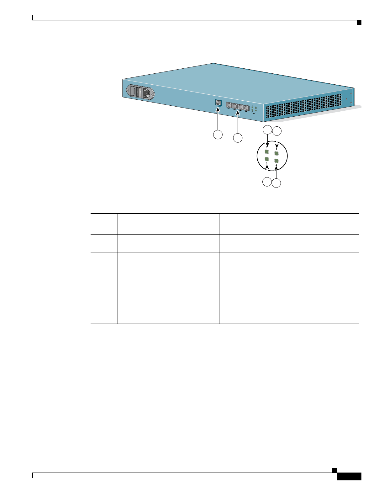
Figure 1-1 Cisco IPVC 3521 BRI Gateway Front Panel
.
Table 1-1 Cisco IPVC 3521 BRI Gateway Front Panel Components
Number Component Description
1 10/100BaseT Ethernet port A full-duplex Ethernet port that connects to the
network through a standard RJ-45 connector.
2 Link LED Lights when there is network activity.
3 Connectivity LED Indicates the type of Ethernet interface that is used:
lights green when the Ethernet interface is
100BaseT; off when the Ethernet interface is
10BaseT.
4 Serial An EIA-TIA-232 port that accepts a female DB-9
connector.
5 RST (Reset) Button Restarts the gateway device.
6 GK Reg LED Lights green when the gateway has an active
registration with the gatekeeper.
7 CD LED Lights green when the connection between the
gateway and BRI line is active.
8 Alarm LED Lights orange when the gateway fails the self test
during boot sequence or when there is a loss of
frame alignment.
9 ACT LED Lights green when there is call activity.
10 Power LED Lights green when power to device is on.
79475
1
4
10
5
10/100BaseT
9
7
6
2
8
3
Page 19
1-3
Administrator’s Guide for Cisco IPVC 3521 BRI Gateway, Cisco IPVC 3526 PRI Gateway, and Cisco IPVC 3540 PRI Gateway
OL-7995-01
Chapter 1 Overview of the Cisco IPVC 3500 Series Gateway
About Cisco IPVC 3500 Series Gateway Products
Figure 1-2 Cisco IPVC 3521 BRI Gateway Rear Panel
About the Cisco IPVC 3526 PRI Gateway
The Cisco IPVC 3526 PRI Gateway enables audio, video, and data communication between H.320
endpoints that connect through ISDN, and H.323 endpoints that connect through a packet-based
network. For voice-over-IP, the gateway enables PSTN voice callers to connect from the ISDN network
to IP voice callers. The Cisco IPVC 3526 PRI Gateway supports one PRI ISDN port.
Figure 1-3 and Ta b l e 1- 3 show and explain the gateway front panel. Figure 1-4 and Ta b l e 1- 4 show and
explain the gateway rear panel.
Table 1-2 Cisco IPVC 3521 BRI Gateway Rear Panel Components
Number Component Description
1 10/100BaseT Ethernet This port is not supported.
2 BRI Ports Physical interface for the BRI line. The port accepts
an RJ-45 connector. This port is not used.
3 Port 1 Activity LED Lights green when there is call activity on BRI port
1.
4 Port 3 Activity LED Lights green when there is call activity on BRI port
3.
5 Port 2 Activity LED Lights green when there is call activity on BRI port
2.
6 Port 4 Activity LED Lights green when there is call activity on BRI port
4.
1
2
4
6
3
5
Page 20
1-4
Administrator’s Guide for Cisco IPVC 3521 BRI Gateway, Cisco IPVC 3526 PRI Gateway, and Cisco IPVC 3540 PRI Gateway
OL-7995-01
Chapter 1 Overview of the Cisco IPVC 3500 Series Gateway
About Cisco IPVC 3500 Series Gateway Products
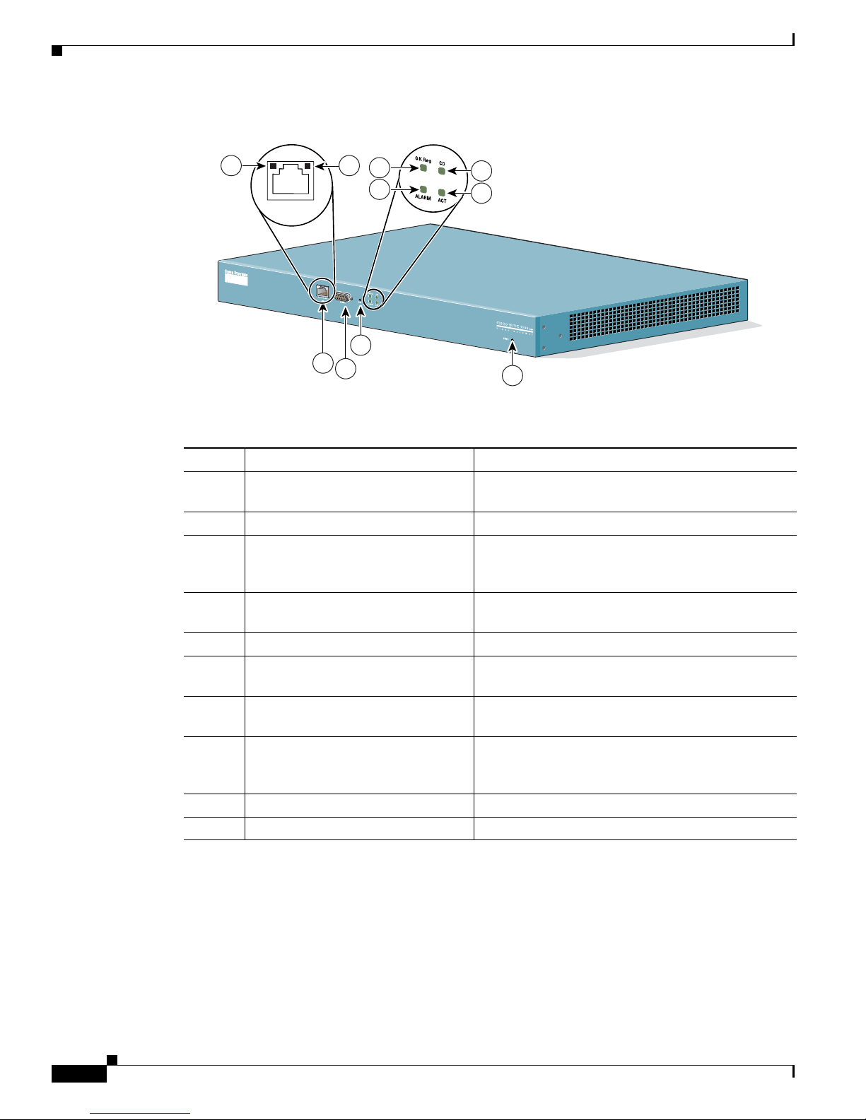
Figure 1-3 Cisco IPVC 3526 PRI Gateway
Table 1-3 Cisco IPVC 3526 PRI Gateway Front Panel Components
Number Component Description
1 10/100BaseT Ethernet port A full-duplex Ethernet port that connects to the
network through a standard RJ-45 connector.
2 Link LED Lights when there is network activity.
3 Connectivity LED Indicates the type of Ethernet interface that is used:
lights green when the Ethernet interface is 100BaseT;
off when the Ethernet interface is 10BaseT.
4 Serial An EIA-TIA-232 port that accepts a female DB-9
connector.
5 RST (Reset) Button Restarts the gateway device.
6 GK Reg LED Lights green when the gateway has an active
registration with the gatekeeper.
7 CD LED Lights green when the connection between the
gateway and PRI line is active.
8 Alarm LED Lights orange when the gateway fails the self test
during boot sequence or when there is a loss of frame
alignment.
9 ACT LED Lights green when there is call activity.
10 Power LED Lights green when power to device is on.
79475
1
4
10
5
10/100BaseT
9
7
6
2
8
3
Page 21
1-5
Administrator’s Guide for Cisco IPVC 3521 BRI Gateway, Cisco IPVC 3526 PRI Gateway, and Cisco IPVC 3540 PRI Gateway
OL-7995-01
Chapter 1 Overview of the Cisco IPVC 3500 Series Gateway
About Cisco IPVC 3500 Series Gateway Products
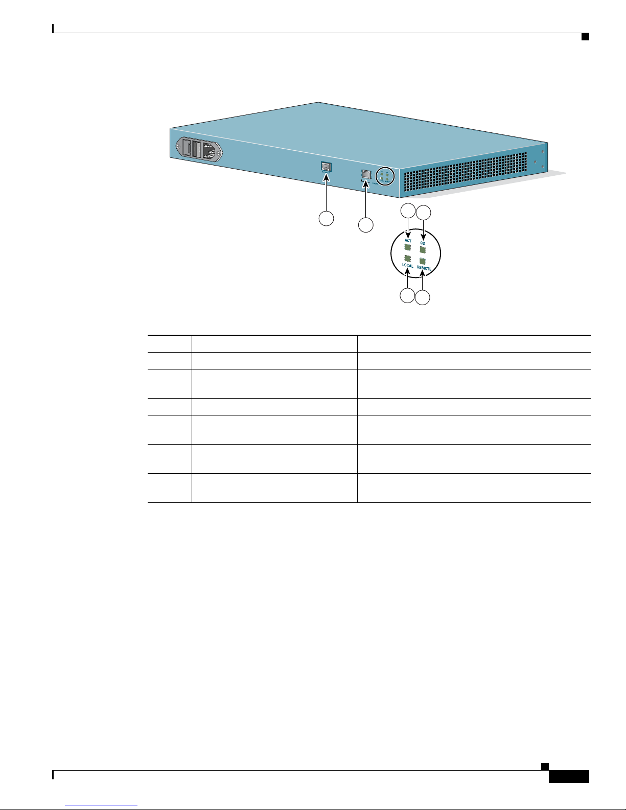
Figure 1-4 Cisco IPVC 3526 PRI Gateway Rear Panel
About the Cisco IPVC 3540 PRI Gateway
The Cisco IPVC 3540 PRI Gateway consists of two modules that insert into a Cisco IPVC 3544 chassis:
the Cisco IPVC 3540 PRI Gateway module and the Rear Transition Module (RTM). The gateway
module installs in the front of the chassis and contains the gateway application apparatus. The RTM
installs in the rear of the chassis and contains the physical interface that connects to the PRI-service
provider equipment. You must install the gateway module and the RTM in corresponding slots. For
example, if you install the gateway module in slot 2 in the front of the chassis, you must install the RTM
in slot 2 in the rear of the chassis.
The Cisco IPVC 3544 chassis requires that the module installed in the top slot provide the system
controls for the cPCI bus. The gateway module has system capability, and can be installed in top slot of
the chassis or in one of the other slots. When you install a gateway module in the top slot, you must
replace the original RTM in the top slot in the rear of the chassis with a gateway RTM.
Table 1-4 Cisco IPVC 3526 PRI Gateway Rear Panel Components
Number Component Description
1 10/100BaseT Ethernet This port is not supported.
2 PRI Port Physical interface for the PRI line. The port accepts
an RJ-48C connector.
3 ACT LED Lights green when there is call activity.
4 Local Lights orange when the gateway reports a loss of
frame alignment.
5 CD Indicates that a PRI line is connected, enabled, and
error free.
6 Remote Lights yellow when the PSTN device reports a loss of
frame alignment.
79471
1
2
4
6
3
5
Page 22
1-6
Administrator’s Guide for Cisco IPVC 3521 BRI Gateway, Cisco IPVC 3526 PRI Gateway, and Cisco IPVC 3540 PRI Gateway
OL-7995-01
Chapter 1 Overview of the Cisco IPVC 3500 Series Gateway
About Cisco IPVC 3500 Series Gateway Products
About Cisco IPVC 3540 PRI Gateway Modules
The Cisco IPVC 3540 PRI Gateway module enables audio, video, and data communication between
H.320 endpoints that connect through ISDN, and H.323 endpoints that connect through a packet-based
network. For voice-over-IP, the gateway enables PSTN voice callers to connect from the ISDN network
to IP voice callers. The Cisco IPVC 3540 PRI Gateway supports two PRI ISDN ports. Figure 1-5 and
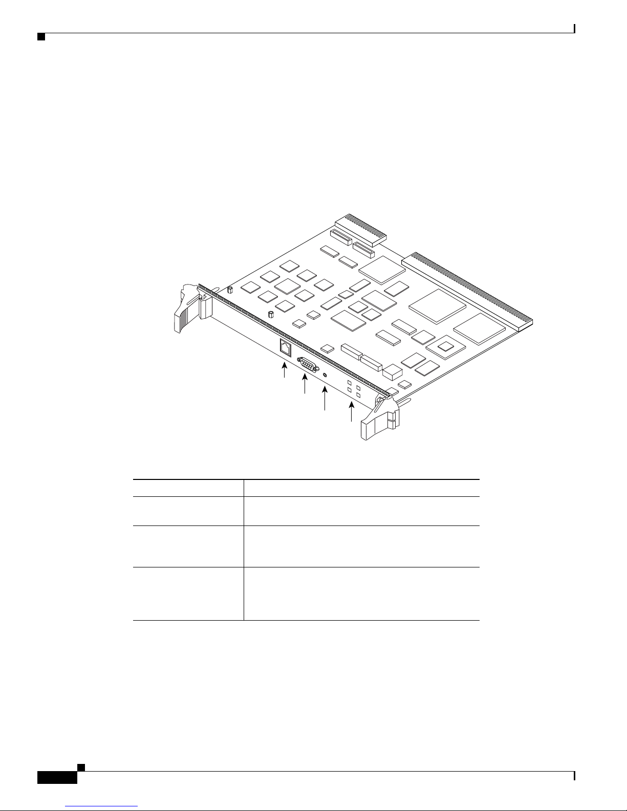
Table 1 -5 show and explain a Cisco IPVC 3540 PRI Gateway module (Cisco IPVC-3540-GW2P).
Figure 1-5 Cisco IPVC 3540 PRI Gateway Module
Table 1-5 Cisco IPVC 3540 PRI Gateway Front Panel Components
Component Description
10/100BaseT Ethernet
port
This is a full-duplex Ethernet port that connects to the
network through a standard RJ-45 connector.
Serial port This is an EIA-TIA-232 port that accepts a male DB-9
connector. The serial port is used to set the IP address
for the module and to monitor gateway activity.
Reset (RST) Button This button resets the module. When the module is in
the top chassis slot, this button resets the cPCI bus as
well, and any other modules connected to the bus are
also reset.
63913
IP
/V
C
-
3
5
4
0
-G
W
2
P
S
1
0
/1
0
0
B
A
S
E
T
-1
G
K
R
e
g
R
S
T
C
D
A
L
A
R
M
A
C
T
S
E
R
IA
L
10/100BaseT-1
Reset Button
Serial Port
LEDs
Page 23

1-7
Administrator’s Guide for Cisco IPVC 3521 BRI Gateway, Cisco IPVC 3526 PRI Gateway, and Cisco IPVC 3540 PRI Gateway
OL-7995-01
Chapter 1 Overview of the Cisco IPVC 3500 Series Gateway
About Cisco IPVC 3500 Series Gateway Products
Caution Do not attempt to install or remove a Cisco IPVC 3540 PRI Gateway module from the chassis top slot
while power is applied to the chassis.
Caution When installing a Cisco IPVC 3540 PRI Gateway module while power is applied to the chassis, install
the RTM before installing the Cisco IPVC 3540 PRI Gateway module.
The Cisco IPVC 3540 PRI Gateway module is capable of providing system functionality for the
Cisco IPVC 3544 chassis. To use the gateway module for system functions, you must install the gateway
module in the top slot in the chassis front, and you must replace the current RTM in the top slot in the
rear of the chassis with the gateway RTM.
Note A module must be installed in the top slot of the chassis to perform the system functions.
LED
• GK Reg—This LED lights up on when the
gateway has an active registration with the
gatekeeper.
• CD—The carrier direct (CD) LED lights green
when all of the enabled PRI lines are connected
and functioning. When one of the enabled PRI
line is not connected or malfunctioning, the CD
LED is off.
• Alarm—This LED indicates an error or loss of
signal in one of the PRI lines. It lights orange
when the gateway fails the self test during boot
sequence or when there is a loss of frame
alignment during a call.
• ACT—The Activity LED indicates there is call
activity.
• SWAP RDY—This LED lights blue to indicate
that it is safe to insert or remove an gateway
module in chassis slots 2, 3, or 4 with the chassis
power on.
When you remove the gateway, the swap ready
feature is activated when you unlock the red
button in the right latch. This feature allows the
gateway to disconnect calls in an orderly manner
and stop its registration with the gatekeeper.
When you instal a gateway in the chassis, this
LED indicates that it is safe to close the latches to
secure the module in the slot.
The RTM must be installed before you install or
remove a gateway.
Table 1-5 Cisco IPVC 3540 PRI Gateway Front Panel Components
Component Description
Page 24
1-8
Administrator’s Guide for Cisco IPVC 3521 BRI Gateway, Cisco IPVC 3526 PRI Gateway, and Cisco IPVC 3540 PRI Gateway
OL-7995-01
Chapter 1 Overview of the Cisco IPVC 3500 Series Gateway
About Cisco IPVC 3500 Series Gateway Products
Caution The chassis system slot, which is the top slot, does not support hot swapping. You must turn off the power
to the chassis before installing or removing a module in the system slot. Failure to do so can damage the
module or the chassis, and disrupt services other modules provide.
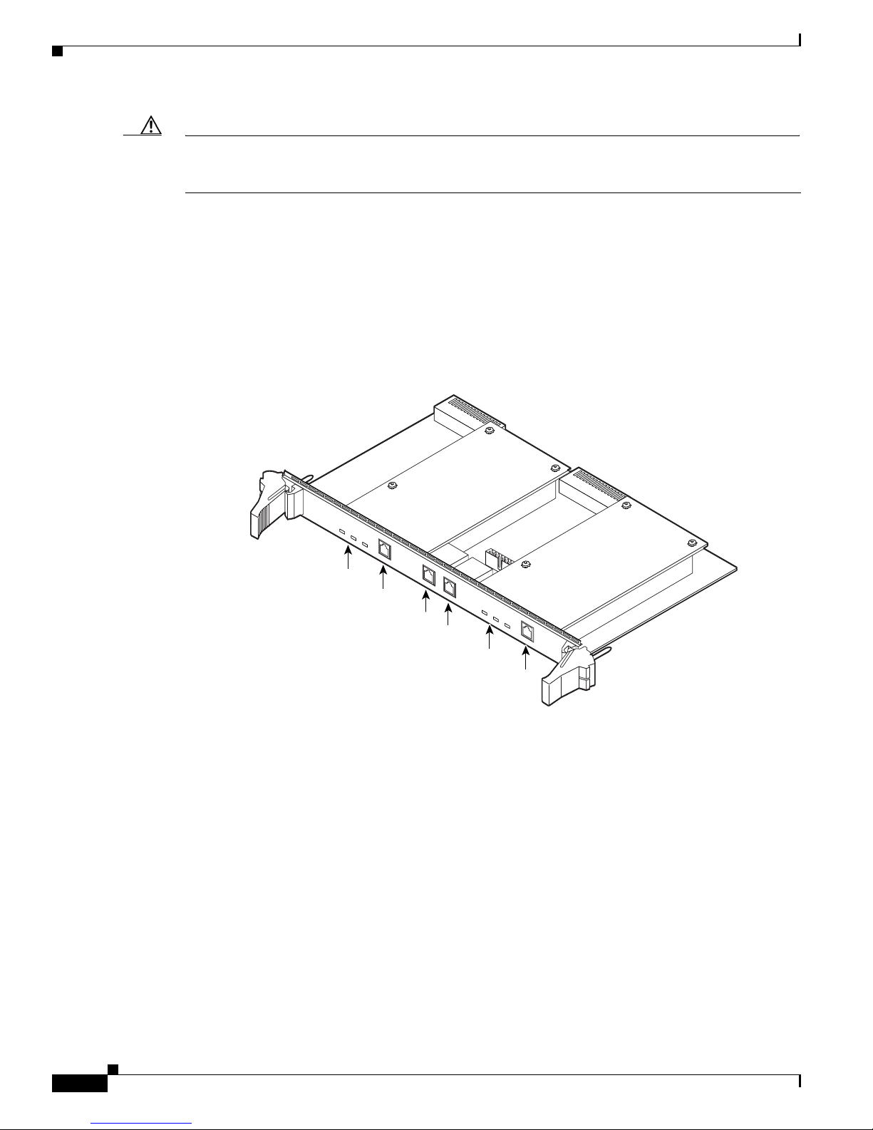
About the Cisco IPVC 3540 RTM Module
Figure 1-6 shows the front panel of the Cisco IPVC 3540 PRI Gateway RTM. The RTM contains
physical interfaces for two PRI lines and the physical interface that allows the gateway to communicate
with the Cisco IPVC 3544 chassis. You must install the RTM in the rear slot that corresponds to the slot
in which you install the gateway. For example, when you install a gateway in slot four in the front of the
chassis, you must install the RTM in slot four in the rear of the chassis.
Figure 1-6 Cisco IPVC 3540 PRI Gateway RTM
Table 1 -6 explains the LEDs and connectors found on the front panel of the
Cisco IPVC 3540 PRI Gateway RTM.
68073
IP
/V
C
-35
4
0
-G
W
2
1
0
/1
0
0
B
a
s
e
T
2
1
0
/
1
0
0
B
a
s
e
T
1
R
E
M
O
T
E
L
O
C
A
L
A
L
A
R
M
1
C
D
1P
R
I
L
I
N
E
1
R
E
M
O
T
E
L
O
C
A
L
A
L
A
R
M
1
C
D
1
P
R
I
L
I
N
E
2
Alarm 2 LEDs
Alarm 1 LEDs
PRI line 2
PRI line 1
10/100BaseT-2
10/100BaseT-1
Page 25

1-9
Administrator’s Guide for Cisco IPVC 3521 BRI Gateway, Cisco IPVC 3526 PRI Gateway, and Cisco IPVC 3540 PRI Gateway
OL-7995-01
Chapter 1 Overview of the Cisco IPVC 3500 Series Gateway
About Cisco IPVC 3500 Series Gateway Features
About Cisco IPVC 3500 Series Gateway Features
Table 1 -7 lists the major features of the Cisco IPVC 3500 Series Gateways.
Table 1-6 Cisco IPVC 3540 PRI Gateway RTM Front Panel Components
Component Description
Alarm 2 The following LEDs are associated with PRI line 2:
• Remote (yellow)—When this LED lights up, it
indicates that there is a loss of frame alignment
between the gateway on PRI port 2 and the ISDN
device communicating with the gateway.
• Local (orange)—When this LED lights up, it
indicates that LAN device communicating with
the gateway on PRI port 2 reports a loss of frame
alignment.
• CD 2—When this LED lights up, it indicates that
PRI port 2 is enabled and has an error-free
connection.
PRI Line 2 This is the physical interface for a PRI line. The port
accepts an RJ-48C connector. When two PRI lines are
connected to the gateway, this interface serves as the
second PRI line.
10/100BaseT-2 Ethernet This port is not supported.
10/100BaseT-1 Ethernet This port is not supported.
Alarm 1 The following LEDs are associated with PRI line 1.
• Remote (yellow)—When this LED lights up, it
indicates that the ISDN device communicating
with the gateway on PRI port 1 reports a loss of
frame alignment.
• Local (orange)—When this LED lights up, it
indicates that LAN device communicating with
the gateway on PRI port 1 reports a loss of frame
alignment.
• CD 1—When this LED lights up, it indicates that
a PRI port 1 is enabled and has an error free
connection.
PRI Line 1 This is the physical interface for a PRI line. The port
accepts an RJ-48C connector. When two PRI lines are
connected to the gateway, this interface serves as the
first PRI line.
Page 26

1-10
Administrator’s Guide for Cisco IPVC 3521 BRI Gateway, Cisco IPVC 3526 PRI Gateway, and Cisco IPVC 3540 PRI Gateway
OL-7995-01
Chapter 1 Overview of the Cisco IPVC 3500 Series Gateway
About Cisco IPVC 3500 Series Gateway Features
Table 1-7 Cisco IPVC 3500 Series Gateway Feature Summary
Feature Description
Interoperability The Cisco IPVC 3500 Series Gateway provides a
high degree of interoperability with other H.323
compliant gateways, gatekeepers, terminals,
proxy, and Multipoint Control Unit (MCU)
products by being based on the H.320 standard
and H.323 protocol stack.
Web-based management The Cisco IPVC 3500 Series Gateway features
the Gateway interface. This is a web interface
used to configure and monitor the
Cisco IPVC 3500 Series Gateway. You can view
and modify all aspects of the gateway
configuration from a remote location using a
Java-enabled web browser.
SNMP management The Cisco IPVC 3500 Series Gateway features
Simple Network Management Protocol (SNMP)
management that supports all aspects of
monitoring, diagnostics, configuration, and
trapping.
Diagnostics The Cisco IPVC 3500 Series Gateway features
front and rear panel LED indicators that display
status for the unit. You can also access remote
diagnostics of the unit through the Gateway
interface, Telnet, SNMP, or a serial port.
Network load balancing The Cisco IPVC 3500 Series Gateway supports
load balancing on the network by communicating
with a gatekeeper through H.323 RAI (Resource
Available Indication)/RAC (Resource Available
Confirmation) messages.
T.120 data collaboration The Cisco IPVC 3500 Series Gateway supports
data transfers in calls between ISDN and IP by
using high speed T.120 in HMLP and VarMLP
formats.
Quality of service (QoS) The Cisco IPVC 3500 Series Gateway features
configurable coding of media packets to achieve
QoS routing priority on the Internet Protocol (IP)
network. The Type of Service (ToS) bits of the IP
datagram header can be configured for priority
level.
Dial plan The Cisco IPVC 3500 Series Gateway supports a
simplified dial plan for outbound dialing using a
single universal prefix. Using the dial plan, the
gateway automatically detects the capabilities
received in the Setup message from the IP
endpoint and sets the same bit rate for the ISDN
(or serial interface) side of the call.
Page 27

1-11
Administrator’s Guide for Cisco IPVC 3521 BRI Gateway, Cisco IPVC 3526 PRI Gateway, and Cisco IPVC 3540 PRI Gateway
OL-7995-01
Chapter 1 Overview of the Cisco IPVC 3500 Series Gateway
About Cisco IPVC 3500 Series Gateway Features
Direct dialing and call routing The Cisco IPVC 3500 Series Gateway dial plan
supports the following direct dialing and call
routing facilities:
• Direct Inward Dialing (DID)
–
Multiple Subscriber Network (MSN)
–
Q.931 Sub-addressing Information
Element
• Internal and External Interactive Voice
Response (IVR)
• TCS4
• Default extension
Access control The Cisco IPVC 3500 Series Gateway features
password controlled access to the Gateway
interface. Up to ten different administrator access
profiles can be defined for the gateway.
DTMF translation The Cisco IPVC 3500 Series Gateway supports
translation between in-band Dual Tone
Multi-Frequency (DTMF) signals (on the ISDN
side) and out-of-band H.245 messages (on the IP
side). DTMF translation occurs for voice and
video calls.
Dual video The Cisco IPVC 3500 Series Gateway supports
dual video streams for a single call using
TANDBERG Duo Video™ technology. Dual
video streams enable a screen to carry video
images from one source while simultaneously
displaying images from a second source.
Hot swap The Cisco IPVC 3500 Series Gateway features
hot swap functionality that you can use to remove
and replace gateway cards under power.
Conceal caller ID The Cisco IPVC 3500 Series Gateway supports a
conceal caller ID feature that instructs the
gatekeeper to conceal the identity of the calling
endpoint on the IP or ISDN network, whether the
presentation restricted feature is enabled or not.
H.323 fast start The Cisco IPVC 3500 Series Gateway H.323 fast
start feature enables endpoints to join a voice
conference in the gateway more quickly.
Table 1-7 Cisco IPVC 3500 Series Gateway Feature Summary
Feature Description
Page 28

1-12
Administrator’s Guide for Cisco IPVC 3521 BRI Gateway, Cisco IPVC 3526 PRI Gateway, and Cisco IPVC 3540 PRI Gateway
OL-7995-01
Chapter 1 Overview of the Cisco IPVC 3500 Series Gateway
About Cisco IPVC 3500 Series Gateway Features
ISDN rollover The Cisco IPVC 3500 Series Gateway features
ISDN rollover. In this feature, the gateway sends
a “busy out” channel request to the PSTN switch
when the current PRI connection is left with less
than a predefined number of available B channels.
The PSTN switch “rolls over” to the next
available gateway.
Note This feature is supported on the
CiscoIPVC3500PRIGateways only.
Network Specific Facility The Cisco IPVC 3500 Series Gateway provides
support for Network Specific Facility Information
Elements (NSF IEs) enables system
administrators to specify to service providers the
equipment, service, or network through which
they want a call routed.
Note This feature is supported on the
CiscoIPVC3500PRIGateways only.
ISDN connection failure The Cisco IPVC 3500 Series Gateway responds
to ISDN connection failure events, by
unregistering from its gatekeeper. The gatekeeper
is forced to send new IP-to-ISDN calls through a
different gateway, thus ensuring high call
completion rates. The gateway re-registers to the
gatekeeper when the ISDN connection is restored.
Downspeeding The Cisco IPVC 3500 Series Gateway features In
downspeeding functionality. In the downspeeding
feature, the Cisco IPVC 3500 Series Gateway
attempts to reconnect a disconnected video call
either at a lower bandwidth or as a voice call.
Downspeeding contributes to a higher percentage
of call completion on the network. The gateway
supports downspeeding at call setup and in
mid-call.
Multiple trap server support The Cisco IPVC 3500 Series Gateway supports
up to three SNMP trap servers.
H.239 support The Cisco IPVC 3500 Series Gateway supports
H.239 in ISDN-to-IP calls and in IP-to-ISDN
calls.
H.235 encryption for H.323 calls The Cisco IPVC 3500 Series Gateway supports
H.325-compliant encryption for calls over IP
networks.
Table 1-7 Cisco IPVC 3500 Series Gateway Feature Summary
Feature Description
Page 29

1-13
Administrator’s Guide for Cisco IPVC 3521 BRI Gateway, Cisco IPVC 3526 PRI Gateway, and Cisco IPVC 3540 PRI Gateway
OL-7995-01
Chapter 1 Overview of the Cisco IPVC 3500 Series Gateway
About Cisco IPVC 3500 Series Gateway Features
Table 1 -8 lists features for specific Cisco IPVC 3500 Series Gateways.
Peer-to-peer connectivity The Cisco IPVC 3500 Series Gateway supports
connectivity to the IP network through a
gatekeeper, or directly to a peer device such as
Cisco CallManager.
IP network connections The Cisco IPVC 3500 Series Gateway has one
10/100Base-T Ethernet IP port (on the front
panel) and connects to an IP segment through a
direct connection to a network switch. The
Ethernet ports on the rear panel are for future use.
Table 1-7 Cisco IPVC 3500 Series Gateway Feature Summary
Feature Description
Table 1-8 Cisco IPVC 3500 Series Gateway Feature Specifics
Feature
Cisco IPVC 3540 PRI
Gateway
Cisco IPVC 3526 PRI
Gateway
Cisco IPVC 3521 BRI
Gateway
Supported ports 2 PRI ISDN port 1 PRI ISDN ports 4 BRI ISDN ports
Supported video
conferencing
protocols
H.320, H.323 (using Stack v4.0)
Supported audio
codecs
The term audio transcoded video calls refers to the process whereby an audio
stream in a multimedia call can be transcoded from one codec type to another.
Basic and advanced audio coding supported codecs are: G.711, G.722,
G.722.1, G.723.1, G.728
Audio Transcoding
(optional for the
Cisco
IPVC 3540 PRI
Gateway)
G.711 (ISDN) < > G.723.1
(IP) for up to 30 voice
channels.
G.711 (ISDN) < >
G.723.1 (IP) for up to 60
voice channels.
G.711 (ISDN) < >
G.723.1 (IP) for up
to 8 voice channels.
G.711 (IP) < > G.728 (ISDN) for up to 20 audio
transcoded video channels.
G.711 (IP) < >
G.728 (ISDN) for
up to 8 audio
transcoded video
channels.
The gateway automatically performs A-Law
G.711-to-µ-Law G.711 translation between the IP and
ISDN sides if needed.
NOTE: When your unit includes both a gateway and
Cisco IPVC 35xx MCU, G.728 transcoding is supported
on the Cisco IPVC 35xx MCU only.
Supported video
protocols
H.261, H.263, H.263+ (Annexes F, J and N), H.263++ (Annex W), H.264.
Supported video
resolutions
VGA, XGA, SVGA, SIF, 4SIF, CIF, QCIF, 4CIF, 16CIF.
Page 30

1-14
Administrator’s Guide for Cisco IPVC 3521 BRI Gateway, Cisco IPVC 3526 PRI Gateway, and Cisco IPVC 3540 PRI Gateway
OL-7995-01
Chapter 1 Overview of the Cisco IPVC 3500 Series Gateway
About Cisco IPVC 3500 Series Gateway Features
Supported
bandwidths (Kbps)
56, 64, 112, 128, 168, 192, 224, 256, 280, 320, 336, 384,
448, 512, 672, 768, 1288, 1472, 1680 and 1920.
56, 64, 112, 128,
224, 256, 336, 384
and 512.
NOTE: Bandwidth rates of 256 Kbps and up support the G.722 audio codec.
Call handling
capabilities
For 1 x PRI T1 line:
23 ports (voice)
23 ports 1B (video and data)
11 ports 2B (video and data)
3 ports 6B (video and data)
For 2 x PRI T1 lines:
46 ports (voice)
30 ports 1B (video and data)
23 ports 2B (video and data)
7 ports 6B (video and data)
For 1 x PRI E1 line:
30 ports (voice)
30 ports 1B (video and data)
15 ports 2B (video and data)
5 ports 6B (video and data)
For 2 x PRI E1 lines:
60 ports (voice)
30 ports 1B/2B (video and
data)
10 ports 6B (video and data)
For 1 x PRI T1 line:
23 ports (voice)
23 ports 1B (video and
data)
11 ports 2B (video and
data)
3 ports 6B (video and
data)
For 1 x PRI E1 line:
30 ports (voice)
30 ports 1B (video and
data)
15 ports 2B (video and
data)
5 ports 6B (video and
data)
For 4 x BRI lines:
8 voice-only calls
or 8 video calls or
any combination of
the two:
1 call x 512 Kbps
1 call x 384 Kbps +
2 calls x 256 Kbps
4 calls x 128 Kbps
8 calls x 64 Kbps
Table 1-8 Cisco IPVC 3500 Series Gateway Feature Specifics
Feature
Cisco IPVC 3540 PRI
Gateway
Cisco IPVC 3526 PRI
Gateway
Cisco IPVC 3521 BRI
Gateway
Page 31

1-15
Administrator’s Guide for Cisco IPVC 3521 BRI Gateway, Cisco IPVC 3526 PRI Gateway, and Cisco IPVC 3540 PRI Gateway
OL-7995-01
Chapter 1 Overview of the Cisco IPVC 3500 Series Gateway
About Cisco IPVC 3500 Series Gateway Features
Line quality Supports line echo cancellation, H.323 Fast Start and DTMF detection for
voice and video calls.
IP network
connection
I10/100Base-T Ethernet connection (on the front panel). A second connection
is for future use.
Serial control port
(DB-9) connection
RS-232 DTE 9-pin D-type connection on front panel for connection to a PC
terminal or an external modem.
Supported signaling
protocols
5ESS and 4ESS, DMS100, National ISDN, Euro-ISDN,
VN6 Dialing (France), NTT (Japan), Hong Kong Dialing
(Hong Kong), Support for Taiwan PRI system.
DMS100, National
ISDN, 5ESS
Custom/Multipoint
(US, Taiwan)
5ESS PTP (US,
Tai wan )
ETSI (France,
Europe, Taiwan,
Hong Kong)
ETSI PTP (France,
Europe, Taiwan)
VN6 Dialing
(France)
Austel 1 Dialing
(Australia)
KDD, NTT (Japan)
Hong Kong Dialing
(Hong Kong).
PRI interface (PRI
Gateways only)
Configurable E1/T1 PRI network interface.
Support for fractional E1/T1 channel selection.
Configurable as terminal side (TE) or network side (NT)
device.
Configurable Long Haul PRI module (supported in Japan
only).
N/A
Switch information
(PRI Gateways only)
Numbering Plan Identifier (NPI), Type of Number
(TON) and Network Specific Facility (NSF) information
elements are configurable for each PRI port.
N/A
Bonding calls (PRI
Gateways only)
Internal Imux providing calls at 128 Kbps (2B) up to full
PRI of 1472 Kbps (23B) for T1 and up to full PRI of
1920 Kbps (30B) for E1 using bonding mode 1.
Parallel dialing for bonded calls.
Internal Imux
providing calls at
128 Kbps (2B) up
to 512 Kbps (8B)
using bonding
mode 1.
Internal IVR
capacity
30 simultaneous calls. 8 simultaneous
calls.
Table 1-8 Cisco IPVC 3500 Series Gateway Feature Specifics
Feature
Cisco IPVC 3540 PRI
Gateway
Cisco IPVC 3526 PRI
Gateway
Cisco IPVC 3521 BRI
Gateway
Page 32

1-16
Administrator’s Guide for Cisco IPVC 3521 BRI Gateway, Cisco IPVC 3526 PRI Gateway, and Cisco IPVC 3540 PRI Gateway
OL-7995-01
Chapter 1 Overview of the Cisco IPVC 3500 Series Gateway
About Cisco IPVC 3500 Series Gateway Applications and Topologies
About Cisco IPVC 3500 Series Gateway Applications and
Topologies
The Cisco IPVC 3500 Series Gateway supports multimedia conferencing by translating between H.323
and H.320 protocols. Examples of network applications that use the gateway include:
• Multimedia conferencing (See the “About Multimedia Conferencing” section on page 1-16)
• Point-to-Point conferencing (See the “About Point-to-Point Conferencing” section on page 1-17)
• Multipoint conferencing (See the “About Multipoint Conferencing” section on page 1-17)
About Multimedia Conferencing
The Cisco IPVC 3500 Series Gateway enables H.323 endpoints on the IP network to communicate with
an H.320 terminal, an ISDN phone, or a regular phone on a circuit-switched public network without
having to connect directly to these networks. The gateway allows all IP network terminals to support
video conferences without connecting every desktop computer to an ISDN line (see Figure 1-7).
Figure 1-7 Multimedia Conferencing through the Gateway
Typical multimedia conferencing applications include:
• Business video conferencing
• Distance learning
• Tel e m e dicine
• Video-enabled call centers
• Tel e c o mm uting
H.323
Terminal
92869
H.323
Terminal
H.323
Terminal
IP phone
IP
IP phone
IP
network
IP
IP phone
IP
ISDN
Cisco IPVC
Gateway
Cisco IPVC
chassis/unit
PSTN
Page 33

1-17
Administrator’s Guide for Cisco IPVC 3521 BRI Gateway, Cisco IPVC 3526 PRI Gateway, and Cisco IPVC 3540 PRI Gateway
OL-7995-01
Chapter 1 Overview of the Cisco IPVC 3500 Series Gateway
About Cisco IPVC 3500 Series Gateway Applications and Topologies
About Point-to-Point Conferencing
The Cisco IPVC 3521 BRI Gateway enables direct video, voice, and data communication between an
H.320 (ISDN) terminal and H.323 (IP) terminals at bandwidths of up to 512 Kbps (4 BRI lines) using
bonding mode 1 (see Figure 1-8).
The Cisco IPVC 3526 PRI Gateway and Cisco IPVC 3540 PRI Gateway enable direct video, voice, and
data communication between an H.320 (ISDN) terminal and H.323 (IP) terminals at bandwidths of up
to 1472 Kbps (23B bonding for T1) and up to 1920 Kbps (30B bonding for E1) (see Figure 1-8).
Figure 1-8 Multimedia Conferencing through the Gateway
About Multipoint Conferencing
Together with the Cisco IPVC 35xx MCU, the Cisco IPVC 3500 Series Gateway enables H.320 ISDN
terminals to participate in a mixed ISDN-IP multipoint multimedia conference with IP network
endpoints (see Figure 1-9).
For example, when an H.320 ISDN terminal wants to participate in a multipoint conference with H.323
IP endpoints, the H.320 ISDN terminal can either join the multipoint conference by dialing to the
gateway, or be invited into the conference by one of the participating IP endpoints. In either case, the
gateway connects the ISDN terminal to the Cisco IPVC 35xx MCU enabling it to participate in the
multipoint conference.
92870
H.323
Terminal
H.323
Terminal
IP
network
ISDN
Cisco IPVC
Gateway
Cisco IPVC
chassis/unit
Page 34

1-18
Administrator’s Guide for Cisco IPVC 3521 BRI Gateway, Cisco IPVC 3526 PRI Gateway, and Cisco IPVC 3540 PRI Gateway
OL-7995-01
Chapter 1 Overview of the Cisco IPVC 3500 Series Gateway
About Cisco IPVC 3500 Series Gateway Applications and Topologies
Figure 1-9 Mixed ISDN-IP Multipoint Multimedia Conference
About Cisco IPVC 3500 Series Gateway IP Network Connections
The Cisco IPVC 3500 Series Gateway features one 10/100Base-T Ethernet IP port (on the front panel)
and connects to an IP segment through a direct connection to a network switch. The Ethernet ports on
the rear panel are for future use.
About Cisco IPVC 3500 Series Gateway ISDN Network Connections
The Cisco IPVC 3521 BRI Gateway features four BRI ISDN connections. Each BRI line provides two
B channels and one D signalling channel.
The Cisco IPVC 3526 PRI Gateway and Cisco IPVC 3540 PRI Gateway feature configurable E1/T1
PRI ISDN connections. When configured as an E1 connection, each port provides 30 B channels and one
D signaling channel. When configured as a T1 connection, each port provides 23 B channels and one D
signaling channel. The type of line available depends on your local ISDN provider. You configure the
gateway PRI port to an E1 or T1 interface accordingly. In addition, you can choose to activate only
specific channels by using fractional channel selection.
You can connect the gateway directly to a PRI or BRI line provided by your local ISDN provider, or to
a local private branch exchange (PBX) that provides the BRI (as shown in figures Figure 1-10 and
Figure 1-11) or PRI connection (as shown in Figure 1-12 and Figure 1-13).
H.323
Terminal
92871
H.323
Terminal
H.323
Terminal
H.323
Terminal
H.323
Terminal
H.320
Terminal
H.320
Terminal
H.320
Terminal
IP phone
IP
network
IP
IP phone
IP
ISDN
Cisco IPVC
Gateway
Cisco IPVC MCU
Cisco IPVC
chassis/unit
Page 35

1-19
Administrator’s Guide for Cisco IPVC 3521 BRI Gateway, Cisco IPVC 3526 PRI Gateway, and Cisco IPVC 3540 PRI Gateway
OL-7995-01
Chapter 1 Overview of the Cisco IPVC 3500 Series Gateway
About Cisco IPVC 3500 Series Gateway Applications and Topologies
Figure 1-10 Connecting the BRI Gateway Directly to a Central Office Switch
Figure 1-11 Connecting the BRI Gateway Directly to a PBX that Provides a BRI Line
Figure 1-12 Connecting the PRI Gateway Directly to a Central Office Switch
92875
H.323
Terminal
IP phone
IP
IP
network
Public
BRI
Central office
switch
Private
Cisco IPVC
Gateway
Cisco IPVC
chassis/unit
92876
H.323
Terminal
IP phone
IP
IP phone
IP
IP phone
IP
IP
network
Public
Central office
switch
Private
Cisco IPVC
Gateway
Cisco IPVC
chassis/unit
PBX
BRI
92873
H.323
Terminal
IP phone
IP
IP
network
Public
PRI T1/E1
Central office
switch
Private
Cisco IPVC
Gateway
Cisco IPVC
chassis/unit
Page 36

1-20
Administrator’s Guide for Cisco IPVC 3521 BRI Gateway, Cisco IPVC 3526 PRI Gateway, and Cisco IPVC 3540 PRI Gateway
OL-7995-01
Chapter 1 Overview of the Cisco IPVC 3500 Series Gateway
About Cisco IPVC 3500 Series Gateway Functionality
Figure 1-13 Connecting the PRI Gateway to a PBX that Provides a PRI Line
About Cisco IPVC 3500 Series Gateway Functionality
This section discusses the following topics:
• About Call Handling Capacity, page 1-20
• About Cisco IPVC 3500 Series Gateway Call Bandwidth Overhead, page 1-21
• About Peer-to-Peer Connectivity, page 1-21
About Call Handling Capacity
Table 1 -9 lists the maximum call handling capacity of the Cisco IPVC 3521 BRI Gateway for 4 x BRI
lines, 8 voice-only calls, or 8 video calls, or any combination of the two.
Table 1 -10 lists the maximum call handling capacity of the Cisco IPVC 3526 PRI Gateway and
Cisco IPVC 3540 PRI Gateway when using one or two E1 PRI lines, and one or two T1 PRI lines for
different types of calls.
92874
H.323
Terminal
IP phone
IP
IP phone
IP
IP phone
IP
IP
network
Public
Central office
switch
Private
Cisco IPVC
Gateway
Cisco IPVC
chassis/unit
PBX
PRI T1/E1
Table 1-9 Cisco IPVC 3521 BRI Gateway Call Handling Capacity
Number of Calls Capacity
1 384 Kbps+ or 412 Kbps
2 256 Kbps
4 128 Kbps
8 64 Kbps
Page 37

1-21
Administrator’s Guide for Cisco IPVC 3521 BRI Gateway, Cisco IPVC 3526 PRI Gateway, and Cisco IPVC 3540 PRI Gateway
OL-7995-01
Chapter 1 Overview of the Cisco IPVC 3500 Series Gateway
About Cisco IPVC 3500 Series Gateway Functionality
Note Enabling ISDN-to-IP DTMF detection in the Cisco IPVC 3526 PRI Gateway for video calls reduces the
number of supported calls by half.
About Cisco IPVC 3500 Series Gateway Call Bandwidth Overhead
According to the H.320 standard, the available bandwidth allocated to a call at any given bit rate will
always be slightly less than the stated maximum for the following reasons:
• All stated maximum call bandwidths include provision for control, audio, video, and data traffic.
• Video traffic on the ISDN side contains additional bits for error correction purposes which also
consume bandwidth. Video traffic on the IP side does not include this additional load.
• Opening an audio channel further reduces the bandwidth available to the video traffic.
For example, a call at 384 Kbps actually has only 363 Kbps available to it. Control and error correction
account for the remaining 21 Kbps
About Peer-to-Peer Connectivity
The Cisco IPVC 3500 Series Gateway supports the following types of connectivity to the IP network
• Through a gatekeeper
• Directly to a peer device such as Cisco CallManager without the need for a gatekeeper.
Table 1-10 Cisco IPVC 3526 PRI Gateway and Cisco IPVC 3540 PRI Gateway Call Handling
Capacity
Call Type
Maximum
Number of Calls
Using 1 x E1 PRI
Line
Maximum
Number of Calls
Using 1 X T1 PRI
Line
Maximum Number
of Calls Using 2 x E1
PRI Lines
Maximum Number
of Calls Using 2 x T1
PRI Lines
voice (64 Kbps) 30 23 60 46
2B video (128
Kbps)
15 11 30 23
6B video (384
Kbps)
5310 7
12B video (768
Kbps)
215 3
Page 38

1-22
Administrator’s Guide for Cisco IPVC 3521 BRI Gateway, Cisco IPVC 3526 PRI Gateway, and Cisco IPVC 3540 PRI Gateway
OL-7995-01
Chapter 1 Overview of the Cisco IPVC 3500 Series Gateway
About Cisco IPVC 3500 Series Gateway Functionality
Page 39

CHAPTER
2-1
Administrator’s Guide for Cisco IPVC 3521 BRI Gateway, Cisco IPVC 3526 PRI Gateway, and Cisco IPVC 3540 PRI Gateway
OL-7995-01
2
Installing the Cisco IPVC 3500 Series Gateway
This chapter describes the following topics:
• Preparing for Installation of the Cisco IPVC 3521 BRI Gateway, page 2-2
• Preparing for Installation of the Cisco IPVC 3500 PRI Gateways, page 2-2
• Verifying the Package Contents, page 2-3
• Installing the Cisco IPVC 3521 BRI Gateway in a Rack, page 2-4
• Installing the Cisco IPVC 3526 PRI Gateway in a Rack, page 2-5
• Installing the Cisco IPVC 3540 PRI Gateway, page 2-5
• Assigning the IP Address for Cisco IPVC 3500 Series Gateways, page 2-9
• Changing the Configuration Tool Login Password, page 2-11
• Connecting the Cisco IPVC 3521 BRI Gateway to the Network, page 2-11
• Connecting Cisco IPVC 3500 PRI Gateways to the Network, page 2-12
• Connecting PRI Lines to the Cisco IPVC 3500 PRI Gateways, page 2-12
• Connecting the Cisco IPVC 3500 Series Gateway to a Power Source, page 2-12
• Installing Online Help on the Network, page 2-13
• Starting the Gateway Interface, page 2-14
• About Gateway Interface Users, page 2-14
• Viewing Board Basic Parameters, page 2-15
• Viewing and Changing IP Address Settings, page 2-18
• Configuring the Administrator Interface Web Server Port, page 2-18
• Specifying the Location of Gateway Online Help Files, page 2-19
• Configuring Gateway Security, page 2-19
• Configuring Cisco IPVC 3544 Chassis Parameters, page 2-20
• Saving Configuration Settings, page 2-22
• Importing Configuration Files, page 2-23
Page 40

2-2
Administrator’s Guide for Cisco IPVC 3521 BRI Gateway, Cisco IPVC 3526 PRI Gateway, and Cisco IPVC 3540 PRI Gateway
OL-7995-01
Chapter 2 Installing the Cisco IPVC 3500 Series Gateway
Preparing for Installation of the Cisco IPVC 3521 BRI Gateway
Preparing for Installation of the Cisco IPVC 3521 BRI Gateway
The Cisco IPVC 3521 BRI Gateway prepares the signaling for outbound videoconference calls that are
transmitted over Integrated Services Digital Network (ISDN) networks. For videoconference information
to arrive at its destination, you must work with the BRI service provider to ensure that the gateway and
the ISDN service are compatible. You must gather information about the service provider equipment and
provide the service provider with information about the gateway.
Before you order BRI service or connect the Cisco IPVC 3521 BRI Gateway to your existing BRI
service, we suggest that you gather the following information.
1. Identify the ISDN provider you want to use as your Local Exchange Carrier (LEC) for local calls.
Note The LEC is the local telephone company that provides ISDN services for your local calling
area and to which your equipment connects.
2. Identify the ISDN provider you want to use as your Interexchange Carrier (IEC) for long-distance
calls.
Note The IEC and the LEC are different companies. Often the LEC will contact the IEC and
provision long-distance service for you. Verify that your LEC performs this task, and contact
an IEC if the LEC does not.
3. Determine how many BRI lines you want to connect to the gateway.
4. Identify the ISDN equipment or signaling format your LEC uses.
5. Determine whether you want to use layer 1 line hunting.
6. Have your ISDN service provider turn off the following switch settings:
• Packet Mode Data on the D channel
• Terminal Display Text
• EKTS
• Call Appearances
• Key Hold
• ACO
Preparing for Installation of the Cisco IPVC 3500 PRI Gateways
Warning During this procedure, wear grounding wrist straps to avoid ESD damage to the card. Do not directly touch
the backplane with your hand or any metal tool, or you could shock yourself.
The following are necessary for installing a Cisco IPVC 3500 PRI Gateway:
• Cisco IPVC 3544 chassis for the Cisco IPVC 3540 PRI Gateway module
• PC with a serial port and terminal emulation software to assign to the gateway an IP address
Page 41

2-3
Administrator’s Guide for Cisco IPVC 3521 BRI Gateway, Cisco IPVC 3526 PRI Gateway, and Cisco IPVC 3540 PRI Gateway
OL-7995-01
Chapter 2 Installing the Cisco IPVC 3500 Series Gateway
Verifying the Package Contents
• Dedicated IP address for the gateway
• IP address of the router the gateway uses to communicate across the network
• IP address of the H.323 gatekeeper with which you want the gateway to register
• 10BaseT or 100BaseT Ethernet cable
• At least one PRI line
• Ambient room temperature range of 32
o
to 104oF (0o to 40oC) with a noncondensing relative
humidity range of 15 to 85 percent
Verifying the Package Contents
This section includes the package contents for the following Cisco IPVC 3500 Series Gateways:
• Cisco IPVC 3521 BRI Gateway(see the “Verifying Package Contents for the
Cisco IPVC 3521 BRI Gateway” section on page 2-3)
• Cisco IPVC 3526 PRI Gateway (see the “Verifying Package Contents for the
Cisco IPVC 3526 PRI Gateway” section on page 2-3)
• Cisco IPVC 3540 PRI Gateway (see the “Verifying Package Contents for the
Cisco IPVC 3540 PRI Gateway” section on page 2-4)
Verifying Package Contents for the Cisco IPVC 3521 BRI Gateway
Your Cisco IPVC 3521 BRI Gateway package contains the following.
• Cisco IPVC 3521 BRI Gateway
• Serial cable
• Mounting rack kit (two brackets and six screws)
• Four rubber feet
• Cisco IPVC Software CD-ROM
• Cisco Information Packet
Inspect the content of the box for shipping damage. Report any damage or missing items to your
distributor or reseller.
Verifying Package Contents for the Cisco IPVC 3526 PRI Gateway
Your Cisco IPVC 3526 PRI Gateway package contains the following.
• Cisco IPVC 3526 PRI Gateway device
• Serial cable
• Mounting rack kit (two brackets and six screws)
• Four rubber feet
• Cisco IPVC Software CD-ROM
Page 42

2-4
Administrator’s Guide for Cisco IPVC 3521 BRI Gateway, Cisco IPVC 3526 PRI Gateway, and Cisco IPVC 3540 PRI Gateway
OL-7995-01
Chapter 2 Installing the Cisco IPVC 3500 Series Gateway
Installing the Cisco IPVC 3521 BRI Gateway in a Rack
• Cisco Information Packet
Verifying Package Contents for the Cisco IPVC 3540 PRI Gateway
Your Cisco IPVC 3540 PRI Gateway module package contains the following:
• Cisco IPVC 3540 PRI Gateway module
• Cisco IPVC 3540 Rear Transition Module for the PRI gateway
• Terminal cable
• Regulatory Compliance and Safety Information for Cisco IPVC 3540 Product Family
• Cisco IPVC Software CD-ROM
• Cisco Information Package
Installing the Cisco IPVC 3521 BRI Gateway in a Rack
You can install the Cisco IPVC 3521 BRI Gateway in a 19-inch rack. The mounting kit supplied with
the gateway includes two brackets for mounting the unit on a rack. This section describes how to install
the mounting brackets.
Procedure
Step 1 Place the unit the right way up on a hard flat surface, with the front panel facing you.
Step 2 Position a mounting bracket over the mounting holes on one side of the unit (see Figure 2-1).
Figure 2-1 Mounting Bracket Installation
Step 3
Pass the three screws through the washers and bracket holes into the gateway, and tighten them securely
with a screwdriver.
Step 4 Repeat Steps 2 and 3 for the other side of the gateway.
Step 5 Insert the unit into the 19-inch rack and secure.
Two screws are needed for each side. These screws are not provided.
Note Make sure that the air vents in the sides of the unit are not blocked.
79472
Page 43

2-5
Administrator’s Guide for Cisco IPVC 3521 BRI Gateway, Cisco IPVC 3526 PRI Gateway, and Cisco IPVC 3540 PRI Gateway
OL-7995-01
Chapter 2 Installing the Cisco IPVC 3500 Series Gateway
Installing the Cisco IPVC 3526 PRI Gateway in a Rack
Installing the Cisco IPVC 3526 PRI Gateway in a Rack
You can install the Cisco IPVC 3526 PRI Gateway in a 19-inch rack. The mounting kit supplied with the
gateway includes two brackets for mounting the unit on a rack. This section describes how to install the
mounting brackets.
Procedure
Step 1 Place the unit the right way up on a hard flat surface, with the front panel facing you.
Step 2 Position a mounting bracket over the mounting holes on one side of the unit (see Figure 2-2).
Figure 2-2 Mounting Bracket Installation
Step 3
Pass the three screws through the washers and bracket holes into the gateway, and tighten them securely
with a screwdriver.
Step 4 Repeat Steps 2 and 3 for the other side of the gateway.
Step 5 Insert the unit into the 19-inch rack and secure.
Two screws are needed for each side. These screws are not provided.
Note Make sure that the air vents in the sides of the unit are not blocked.
Installing the Cisco IPVC 3540 PRI Gateway
The Cisco IPVC 3540 PRI Gateway has two components that you must install in the
Cisco IPVC 3544 chassis: the Cisco IPVC 3540 PRI Gateway module and the PRI rear transition
module (RTM). These modules complement each other. The gateway module installs in the front of the
chassis and provides PRI functionality. The RTM installs in the rear of the chassis and provides the
physical interface for the PRI line. You must install these modules in corresponding slots in the chassis.
That is, if you insert the gateway module in the top slot in the front of the chassis, you must insert the
RTM in the top slot in the rear of the chassis.
The Cisco IPVC 3544 chassis uses a cPCI bus and requires a module with system functionality in the
top slot. This system functionality is embedded in the gateway module and is activated only when the
gateway module is installed in the top slot.
79472
Page 44

2-6
Administrator’s Guide for Cisco IPVC 3521 BRI Gateway, Cisco IPVC 3526 PRI Gateway, and Cisco IPVC 3540 PRI Gateway
OL-7995-01
Chapter 2 Installing the Cisco IPVC 3500 Series Gateway
Installing the Cisco IPVC 3540 PRI Gateway
Caution Cisco IPVC 3540 modules contain ESD-sensitive components. Use proper ESD procedures when
handling the modules. Improper handling can damage the module and cause the module to fail
immediately or at a later time.
Warning
Only trained and qualified personnel should be allowed to install, replace, or service this equipment.
Warning
Before working on a system that has an on/off switch, turn OFF the power and unplug the power cord.
Before opening the chassis, disconnect the telephone-network cables to avoid contact with
telephone-network voltages.
Warning
To avoid electric shock, do not connect safety extra-low voltage (SELV) circuits to telephone-network
voltage (TNV) circuits. LAN ports contain SELV circuits, and WAN ports contain TNV circuits. Some
LAN and WAN ports both use RJ-45 connectors. Use caution when connecting cables.
Warning
The telecommunications lines must be disconnected 1) before unplugging the main power connector
and/or 2) while the housing is open.
Installing the PRI RTM in the Cisco IPVC 3544 Chassis Top Slot
The top slot in the Cisco IPVC 3544 chassis is used to provide system functionality to the cPCI bus. This
functionality is embedded in the gateway module which connects to the bus through the RTM. This
section describes how to install the RTM in the chassis top slot to allow the gateway module to
communicate with the cPCI bus.
Procedure:
Step 1 Disconnect the power cable to the chassis to ensure that the power is turned off.
Step 2 On the back of the chassis, loosen the screws that secure the latches of the top cover panel.
Step 3 Press the red release button and snap the black handles back to open the latches.
Step 4 Slide the RTM out two inches to expose the cable.
Step 5 Remove the 16-pin flat cable attached to the board.
We recommend that you place the blade of a small, flat-blade screwdriver at the base of the cable
connector key, and pry the connector upward to remove the cable.
Caution Damaging the cable results in the LEDs on the chassis not working.
Step 6 Remove the RTM from the chassis.
Step 7 Remove the PRI RTM from the antistatic bag.
Step 8 Align the edges of the PRI RTM with the chassis guide rails.
Page 45

2-7
Administrator’s Guide for Cisco IPVC 3521 BRI Gateway, Cisco IPVC 3526 PRI Gateway, and Cisco IPVC 3540 PRI Gateway
OL-7995-01
Chapter 2 Installing the Cisco IPVC 3500 Series Gateway
Installing the Cisco IPVC 3540 PRI Gateway
Step 9 Slide the RTM halfway into the chassis.
Step 10 Attach the 16-pin flat cable to connector JP2 on the RTM module (see Figure 2-3).
Figure 2-3 Connecting the 16-pin Flat Cable to the RTM
Step 11 Slide the PRI RTM into the chassis until it stops.
Step 12 Use even pressure to push the module further into the slot.
Warning
Do not force the connection. Forcing the connection can bend or damage the pins in the
connector inside the chassis.
Step 13 Snap the latch handles forward to secure the module in the slot.
Secure the PRI RTM screws.
Installing the PRI RTM in a Cisco IPVC 3544 Chassis Slot Other Than the Top
Slot
To install the PRI RTM in chassis slot two, three, or four, perform the following steps.
Warning
If the power to the chassis is on, you must install the RTM before you install the
Cisco IPVC 3540 PRI Gateway module.
Procedure
Step 1 On the back of the chassis, loosen the screws that secure the latches of the top cover panel.
Step 2 Press the red release button and snap the black handles back to open the latches.
Step 3 Remove the cover plate.
Step 4 Remove the PRI RTM from the antistatic bag.
Step 5 Align the edges of the PRI RTM with the chassis guide rails.
Step 6 Slide the RTM into the chassis until it stops.
Step 7 Use even pressure to push the module further into the slot.
63044
90-260VAC
PO
W
ER
HSSHSS
EXTPWR
RESET
U
S
B
2
Page 46

2-8
Administrator’s Guide for Cisco IPVC 3521 BRI Gateway, Cisco IPVC 3526 PRI Gateway, and Cisco IPVC 3540 PRI Gateway
OL-7995-01
Chapter 2 Installing the Cisco IPVC 3500 Series Gateway
Installing the Cisco IPVC 3540 PRI Gateway
Warning
Do not force the connection. Forcing the connection can bend or damage the pins in the
connector inside the chassis.
Step 8 Snap the latch handles forward to secure the module in the slot.
Step 9 Secure the PRI RTM screws.
Warning
Blank faceplates and cover panels serve three important functions: they prevent exposure
to hazardous voltages and currents inside the chassis; they contain electromagnetic
interference (EMI) that might disrupt other equipment; and they direct the flow of cooling
air through the chassis. Do not operate the system unless all cards, faceplates, front covers,
and rear covers are in place.
Installing the Cisco IPVC 3540 PRI Gateway Module
Procedure
Step 1 Perform one of the following:
• If you are installing the gateway module in the chassis top slot, make sure that the power to the
chassis is off. Skip to Step 5; there is no top-slot front cover.
• If you are installing the gateway module in slot two, three, or four, and the power to the chassis is
on, the RTM must be installed before you install the gateway module.
Step 2 In the front of the chassis, loosen the screws that secure the latches of the top cover panel.
Step 3 Press the red buttons on each latch and snap the black handles back.
Step 4 Remove the front panel.
Step 5 Remove the gateway module from the antistatic bag.
Step 6 Insert the gateway module in the guide rails of the top slot and slide the module into the slot until the
module connector makes contact with the chassis connector (see Figure 2-4).
Figure 2-4 Inserting the Cisco IPVC 3540 PRI Gateway Module
Step 7
Press the module firmly into the slot until the face plate is flush with the slot opening.
63043
IP/VC-3540-GW2
PRI -LINE 1
CD1
LOCAL
ALARM 1
ALARM 2
REMOTE
PRI -LINE 2
10/100BaseT-2
10/100BaseT-1
CD2
LOCAL
REMOTE
C
I
S
C
O
I
P
/V
C
-
3
5
4
0
S
e
r
ie
s
P
O
W
E
R
A
L
A
R
M
F
A
N
T
E
M
P
Page 47

2-9
Administrator’s Guide for Cisco IPVC 3521 BRI Gateway, Cisco IPVC 3526 PRI Gateway, and Cisco IPVC 3540 PRI Gateway
OL-7995-01
Chapter 2 Installing the Cisco IPVC 3500 Series Gateway
Assigning the IP Address for Cisco IPVC 3500 Series Gateways
Warning
Do not force the connectors. Forcing the connection can bend or damage the pins in the
connector inside the chassis.
Note If you are installing the module in slots two, three, or four, and the power to the chassis is on,
the SWAP RDY LED on the module front panel turns blue when you slide the module into the
chassis as far as it will go. This means that you can secure the module safely. The LED turns off
when the handles are closed.
Step 8 Snap the latch levers forward to secure the gateway module.
Step 9 If you are installing the module into the top chassis slot, plug the power cable into the chassis and turn
on the power.
Warning
Blank faceplates and cover panels serve three important functions: they prevent exposure
to hazardous voltages and currents inside the chassis; they contain electromagnetic
interference (EMI) that might disrupt other equipment; and they direct the flow of cooling
air through the chassis. Do not operate the system unless all cards, faceplates, front covers,
and rear covers are in place.
Assigning the IP Address for Cisco IPVC 3500 Series Gateways
You must assign the Cisco IPVC 3500 Series Gateway a unique IP address before you connect it to the
network. You can assign the gateway an IP address through the serial port.
You will need to gather the items listed in Table 2-1 to assign an IP address to the gateway.
Table 2-1 Requirements for Setting the IP Address
Requirements Notes
Static IP address for gateway module.
IP address of the default router the
gateway module uses to communicate
over the network.
PC with available serial port and
terminal emulator software installed to
configure the IP address information.
Null EIA/TIA-232 cable (the Terminal
Cable shipped with the unit can be
used).
Page 48

2-10
Administrator’s Guide for Cisco IPVC 3521 BRI Gateway, Cisco IPVC 3526 PRI Gateway, and Cisco IPVC 3540 PRI Gateway
OL-7995-01
Chapter 2 Installing the Cisco IPVC 3500 Series Gateway
Assigning the IP Address for Cisco IPVC 3500 Series Gateways
Procedure
Step 1 Connect the terminal cable that is shipped with the module to the computer serial port and the serial port
on the front panel of the Cisco IPVC 3500 Series Gateway.
Note The terminal cable is a standard null cable.
Step 2 Launch the terminal emulator on the computer.
Step 3 Set the communication values for the terminal emulator as follows:
• 9600 Baud rate
• 8 data bits
• 1 stop bit
• No parity
• No flow control
Step 4 After the terminal emulator session starts, press the RST button on the gateway front panel to reset the
module.
A log of the auto-boot events and a VxWorks banner scrolls across the computer monitor.
Note When the gateway is started for the first time, two VxWorks banners appear every time the unit
is started. The configuration option appears after the second banner.
Step 5 When the message “Press any key to start configuration” appears on the screen, press a key within six
seconds.
An options list appears.
Step 6 At the prompt, enter N and press Enter to select the “to configure default network port values” option.
The “Enter IP Address for Interface N. 1” prompt appears.
Step 7 At the prompt, enter the IP address you want to assign to the module and press Enter.
Caution Do not use leading zeros in the IP address.
The “Enter Default Router IP Address” prompt appears.
Step 8 At the prompt, enter the IP address of the router associated with the segment in which the unit will be
installed and press Enter.
Caution Do not use leading zeros in the IP address.
The “Enter IP Mask <HEX>” prompt appears.
Step 9 At the prompt, enter the subnet mask as follows:
• Convert the subnet mask IP address to hexadecimal, enter the hexadecimal number at the prompt,
and press Enter.
Page 49

2-11
Administrator’s Guide for Cisco IPVC 3521 BRI Gateway, Cisco IPVC 3526 PRI Gateway, and Cisco IPVC 3540 PRI Gateway
OL-7995-01
Chapter 2 Installing the Cisco IPVC 3500 Series Gateway
Changing the Configuration Tool Login Password
Note You can use the computer’s desktop calculator to convert the subnet mask ID to
hexadecimal.
• If a subnet mask is not used, press Enter.
Step 10 Allow the unit to complete the reboot process. A new emulator session begins.
Step 11 Close the terminal emulator session.
Changing the Configuration Tool Login Password
You can use the terminal emulator to change the default password of the default login user before others
can use the Gateway interface.
Procedure
Step 1 Start a terminal emulator session for the Cisco IPVC 3500 Series Gateway.
Step 2 Press the Reset button on the front panel of the gateway.
After 60 seconds, a new terminal emulator session begins on the computer monitor.
Step 3 After the second VxWorks banner scrolls across the screen, the following message appears: “Press any
Key to start the configuration.”
Step 4 Press any key and then press Enter.
A menu appears.
Step 5 At the prompt, enter p and press Enter to select “change the configuration software password.”
The “Enter user name” prompt appears.
Step 6 Enter the user login name for which you want to change the password and press Enter.
The default user name is admin. This is the user name that allows you to access the Gateway interface.
The “Enter new password” prompt appears.
Step 7 Enter the password you want the user to use to log in to the Gateway interface and press Enter.
There is no default password.
Step 8 The configuration menu re-appears.
Step 9 Enter q and press Enter to exit.
Connecting the Cisco IPVC 3521 BRI Gateway to the Network
After you place the Cisco IPVC 3521 BRI Gateway in position, you need to attach network cables to the
unit. The gateway has one Ethernet port and four BRI ports.
Page 50

2-12
Administrator’s Guide for Cisco IPVC 3521 BRI Gateway, Cisco IPVC 3526 PRI Gateway, and Cisco IPVC 3540 PRI Gateway
OL-7995-01
Chapter 2 Installing the Cisco IPVC 3500 Series Gateway
Connecting Cisco IPVC 3500 PRI Gateways to the Network
Procedure
Step 1 Connect a cable from the LAN to the 10/100BaseT port on the front panel of the gateway. The
10/100BaseT port accepts an RJ-45 connector.
Caution The Cisco IPVC 3521 BRI Gateway does not support the Ethernet port on the rear panel. Do
not use.
Step 2 Connect the first ISDN line to the BRI Port 1 in the rear panel of the gateway. The BRI port accepts an
RJ-45 connector.
Step 3 Connect the second ISDN line to the BRI Port 2 in the rear panel of the gateway. The BRI port accepts
an RJ-45 connector.
Step 4 Connect the third ISDN line to the BRI Port 3in the rear panel of the gateway. The BRI port accepts an
RJ-45 connector.
Step 5 Connect the fourth ISDN line to the BRI Port 4 in the rear panel of the gateway. The BRI port accepts
an RJ-45 connector.
Connecting Cisco IPVC 3500 PRI Gateways to the Network
The Cisco IPVC 3500 PRI Gateways can connect to the LAN only through the front panel. The gateway
supports a 10/100BaseT, full-duplex Ethernet interface through an RJ-45 connector.
Procedure
Step 1 Plug an RJ-45 connector attached to an appropriate Ethernet cable into the 10/100BaseT port on the front
panel of the gateway.
Connecting PRI Lines to the Cisco IPVC 3500 PRI Gateways
The Cisco IPVC 3526 PRI Gateway has one PRI port and the ICisco IPVC 3540 PRI Gateway has two
PRI ports. You must connect a PRI line to at least one port. The gateway supports T1 and E1 PRI
configurations.
Connecting the Cisco IPVC 3500 Series Gateway to a Power
Source
This section describes how to supply power to the Cisco IPVC 3500 Series Gateway. The gateway is
equipped with an autoswitching power supply that supports 100-240 VAC at 50/60 Hz.
Page 51

2-13
Administrator’s Guide for Cisco IPVC 3521 BRI Gateway, Cisco IPVC 3526 PRI Gateway, and Cisco IPVC 3540 PRI Gateway
OL-7995-01
Chapter 2 Installing the Cisco IPVC 3500 Series Gateway
Installing Online Help on the Network
Warning
Never defeat the ground conductor or operate the equipment in the absence of a suitably installed
ground conductor. Contact the appropriate electrical inspection authority or an electrician if you are
uncertain that suitable grounding is available.
Procedure
Step 1 Plug a power cord into the power socket on the rear panel of the gateway.
Step 2 Connect the power cable to a grounded AC outlet.
Step 3 Turn the power on.
Installing Online Help on the Network
Online help files for the Cisco IPVC 3500 Series Gateway are shipped on the IPVC Software CD-ROM.
To use the online help in the Gateway interface, you must install the appropriate help files in a shared
directory on your network and register the directory location with the Gateway interface. This section
describes how to install the online help files on your network.
Procedure
Step 1 Identify or create a shared directory on the network in which you want to install the online help files.
Note Make sure that the Gateway interface for each gateway you install can access the shared
directory.
Refer to your network operating system documentation for instructions about how to configure a shared
directory.
Step 2 Insert the Cisco IPVC Software for the IPVC 3500 CD-ROM in the CD-ROM drive of a computer that
is connected to your network.
The CD-ROM is configured to automatically start the installation program.
Step 3 Read the Welcome dialog box and click Next.
Step 4 Click Browse and navigate to the shared directory in which you want to install the online help files, and
click Next.
Step 5 Select the Custom option button and then click Next.
Step 6 Select your Cisco IPVC 3500 Series Gateway type option button, and click Next.
Step 7 In the Program Folders field, enter the name of the folder in which you want to copy the online help
files and click Next.
The CD-ROM copies the files.
Step 8 Click Finish.
Page 52

2-14
Administrator’s Guide for Cisco IPVC 3521 BRI Gateway, Cisco IPVC 3526 PRI Gateway, and Cisco IPVC 3540 PRI Gateway
OL-7995-01
Chapter 2 Installing the Cisco IPVC 3500 Series Gateway
Starting the Gateway Interface
Starting the Gateway Interface
The Gateway interface is a web-based user interface that you can use to view and configure the gateway
hardware and application parameters. You can use the Gateway interface to:
• Set administrative parameters to define access to the gateway device
• Set gateway application parameters that specify how the gateway processes incoming and outgoing
calls
• Set chassis operating parameters for Cisco IPVC 3540 PRI Gateway modules installed in the top
slot of a Cisco IPVC 3544 chassis
Before You Begin
The following requirements are necessary to launch the Gateway interface:
• A Java-enabled internet browser
• The IP address assigned to the gateway you want to configure.
• Administrator level-access
• Only one user can access the Gateway interface at one time.
Procedure
Step 1 Start the web browser.
Step 2 In the URL field, enter:
IP address
Where IP address is the IP address assigned to the gateway for which you want to launch the Gateway
interface.
The Gateway interface login page appears.
Step 3 In the Name field, enter your user name.
Step 4 In the Password field, enter your password.
Step 5 Click Login.
The Gateway interface appears.
About Gateway Interface Users
Users must have the appropriate access level to log in to the Gateway interface. With Administrator-level
access, a user can configure the gateway and monitor gateway activity. You can view and manage the list
of gateway users in the Users tab of the Board section of the Gateway interface. The Users tab displays
all currently configured users and their access levels.
There are three types of Gateway interface users:
• Administrator—Full access to the Gateway interface to configure gateway settings.
• Operator—User can monitor or disconnect calls but otherwise only has read-only access to the
Gateway interface.
Page 53

2-15
Administrator’s Guide for Cisco IPVC 3521 BRI Gateway, Cisco IPVC 3526 PRI Gateway, and Cisco IPVC 3540 PRI Gateway
OL-7995-01
Chapter 2 Installing the Cisco IPVC 3500 Series Gateway
Viewing Board Basic Parameters
• Read-only—User has read-only access to the Gateway interface.
Adding or Editing Gateway Interface Users
In the Users tab of the Board section of the Gateway interface, you can add or edit Gateway interface
users.
Procedure
Step 1 In the Gateway interface, on the sidebar, click Board.
Step 2 Click the Users tab.
Step 3 To add or edit a user, follow these steps:
a. Click Add to add a new user or select an existing one and click Edit.
The Add User or Edit User dialog box appears.
b. In the User name field, enter or edit the user login name
c. In the Access Level field, choose one of the following access levels: Administrator, Operator,
Read only
d. In the Password field, enter or edit the password that the user uses to login to the Gateway interface.
e. In the Confirm Password field, re-enter the password.
Step 4 Click Upload.
Deleting Gateway Interface Users
In the Users tab of the Board section of the Gateway interface, you can delete Gateway interface users.
Procedure
Step 1 In the Gateway interface, on the sidebar, click Board.
Step 2 Click the Users tab.
Step 3 Select a user and click Delete.
Viewing Board Basic Parameters
The Basics tab in the Board section of the Gateway interface provides information about the hardware
and software the Cisco IPVC 3500 Series Gateway uses.
Procedure
Step 1 In the Gateway interface, on the sidebar, click Board.
Page 54

2-16
Administrator’s Guide for Cisco IPVC 3521 BRI Gateway, Cisco IPVC 3526 PRI Gateway, and Cisco IPVC 3540 PRI Gateway
OL-7995-01
Chapter 2 Installing the Cisco IPVC 3500 Series Gateway
Viewing Board Basic Parameters
Step 2 Click the Basics tab
Table 2 -2 describes the elements that appear in the Basics tab.
.
Related Topics
• Configuring Date and Time on the Gateway, page 2-16
• Setting the Gateway Location, page 2-17
• Resetting Default Board Basic Settings, page 2-17
Configuring Date and Time on the Gateway
The gateway has an internal clock that you can set to show the local time of the area in which the gateway
is located.
Procedure
Step 1 On the sidebar, click Board.
Step 2 Click the Basics tab.
Step 3 Locate the Date/Time field and click Change.
The Change Time dialog box appears. The date and time the gateway reports appears in the Set board
time to field.
Table 2-2 Board and Device Basics Page Elements
Element Description
Model number Displays the model number of the gateway.
Location Field where you can specify where the gateway
hardware is located.
Serial Number Displays the serial number the factory assigns to
the module.
Hardware version Displays the version number of the module
hardware.
Date/Time Opens the Change Time dialog box that where
you can set the gateway module’s clock.
Slot number Displays the slot in which the gateway module is
installed.
Software Version Displays the high-level version of the software
installed on the device.
• Details button—Opens the Version Details
message box that shows the current versions
of the component software installed on the
device.
Page 55

2-17
Administrator’s Guide for Cisco IPVC 3521 BRI Gateway, Cisco IPVC 3526 PRI Gateway, and Cisco IPVC 3540 PRI Gateway
OL-7995-01
Chapter 2 Installing the Cisco IPVC 3500 Series Gateway
Viewing Board Basic Parameters
Step 4 To change the date and time, perform the following steps:
a. In the Change field, select the unit that you want to change.
b. In the Set board time to field, click the up or down arrow to change that unit.
Note There is no unit to change AM and PM. This designation rolls automatically when the hour
rolls past 12 backward or forward. Similarly, seconds rolls minutes, minutes roll hours,
hours roll days, and days rolls months.
c. Repeat steps a-b for each unit you want to change.
d. On the toolbar, click Upload to save your changes.
Setting the Gateway Location
You can install the gateway anywhere on your network including at a remote site. The Basics tab of the
Board section in the Gateway interface provides a field that you can use to identify the location where
the gateway is located
Procedure.
Step 1 On the sidebar, click Board.
Step 2 Click the Basics tab.
Step 3 In the Location field, enter the location information about the gateway that you want to display.
The field displays up to 23 characters.
Step 4 On the toolbar, click Upload to save to configuration memory.
Resetting Default Board Basic Settings
In the Basics tab of the Board section of the Gateway interface, you can restore board basic settings to
factory defaults.
Procedure
Step 1 On the sidebar, click Board.
Step 2 Click the Basics tab.
Step 3 Select the Reset to default settings check box.
Page 56

2-18
Administrator’s Guide for Cisco IPVC 3521 BRI Gateway, Cisco IPVC 3526 PRI Gateway, and Cisco IPVC 3540 PRI Gateway
OL-7995-01
Chapter 2 Installing the Cisco IPVC 3500 Series Gateway
Viewing and Changing IP Address Settings
Viewing and Changing IP Address Settings
In the Gateway interface, you can view or change the gateway’s IP address, Ethernet speed, Domain
Name Server (DNS) settings, and duplex settings.
Procedure
Step 1 In the Gateway interface, on the sidebar, click Board.
Step 2 Click the Addressing tab.
Table 2 -3 explains the fields you can view or change in the Addressing tab.
Step 3 If you change any of these settings, when you finish, on the toolbar, click Upload.
Configuring the Administrator Interface Web Server Port
Port 80 is the default Administrator interface web server port. For additional security, you can configure
the web server port as a different port number.
Procedure
Step 1 In the Gateway interface, on the sidebar, click Board.
Step 2 Click the Web tab.
Table 2-3 Addressing Tab Fields
Field Description
IP Address The IP address you want to assign to the gateway.
Router IP field The router IP address you want the gateway to
use.
Subnet Mask The subnet mask you want the gateway to use.
DNS Server IP The IP address of the Domain Name Server
(DNS) that the gateway accesses.
Device DNS Name field The device name of the DNS server that the
gateway accesses (read-only).
Port type The Ethernet port type that the gateway uses
(read-only).
MAC Address The MAC address of the gateway (read-only).
Port settings The Ethernet speed and duplex settings that you
want the gateway to use.
Port status The status of the Ethernet port, which depends on
the settings made in the Port settings field.
Page 57

2-19
Administrator’s Guide for Cisco IPVC 3521 BRI Gateway, Cisco IPVC 3526 PRI Gateway, and Cisco IPVC 3540 PRI Gateway
OL-7995-01
Chapter 2 Installing the Cisco IPVC 3500 Series Gateway
Specifying the Location of Gateway Online Help Files
Step 3 In the Web server port field, enter the port number.
Specifying the Location of Gateway Online Help Files
After you install the online help files, you must register the location of the online help files with your
Cisco IPVC 3500 Series Gateway. You can do this in the Web tab of the Board section in the Gateway
interface.
Procedure
Step 1 In the Gateway interface, on the sidebar, click Board.
Step 2 Click the Web tab.
Step 3 In the Online Help URL field, enter the path to the directory in which the
Cisco IPVC 3500 Series Gateway online help files are stored.
• If the directory is located on a file server, enter:
file://.../shared_directory_name /program_folder
• If the directory is located on a web server, enter:
http://.../shared_directory_name /program_folder
Note The online help files are stored in the folder 3500gw by default. The Gateway interface retrieves
online help text from these files. In the path statement, include all directories in the path up to,
but not including, 3500gw
Step 4 Click Upload.
Configuring Gateway Security
You can configure the access that external programs have to the Cisco IPVC 3500 Series Gateway.
These external programs include Telnet, Simple Network Management Protocol (SNMP), File Transfer
Protocol (FTP), and ICMP (Internet Control Message Protocol, or ping).
Procedure
Step 1 In the Gateway interface, on the sidebar, click Board.
Step 2 Click the Security tab.
Step 3 In the Security mode field, choose the access level you want the gateway to support:
• Standard—Enables SNMP, Telnet, FTP, and ICMP to access the gateway.
• High (no Telnet or Ftp)—Enables access to the gateway only through SNMP and ICMP.
• Maximum (no Telnet, ftp, SNMP, or ICMP)—Disallows external programs to access the gateway.
Page 58

2-20
Administrator’s Guide for Cisco IPVC 3521 BRI Gateway, Cisco IPVC 3526 PRI Gateway, and Cisco IPVC 3540 PRI Gateway
OL-7995-01
Chapter 2 Installing the Cisco IPVC 3500 Series Gateway
Configuring Cisco IPVC 3544 Chassis Parameters
Step 4 In the SNMP Read community and Write community fields, enter default strings used to enable SNMP
communication between the gateway and a external application.
Step 5 On the toolbar, click Upload.
Configuring Cisco IPVC 3544 Chassis Parameters
If your Cisco IPVC 3540 PRI Gateway module is installed in the top slot of the
Cisco IPVC 3544 chassis, then the module also performs PCI bus functions for the chassis. In the
Gateway interface, you can use the System section to monitor chassis functions remotely.
One of the functions the chassis performs is to monitor ambient temperature. You can set temperature
thresholds in the System section. The chassis uses these thresholds to trigger a warning that the ambient
temperature exceeds specification and when the temperature has returned to five degrees below the
warning threshold.
Related Topics
• Viewing the System Section, page 2-20
• Setting Cisco IPVC 3544 Chassis Temperature Thresholds, page 2-22
• Refreshing the System Section, page 2-22
Viewing the System Section
You can view the System section by selecting it in the Gateway interface.
Procedure
Step 1 On the sidebar, click System.
Table 2 -4 lists the elements that appear in the System section.
Page 59

2-21
Administrator’s Guide for Cisco IPVC 3521 BRI Gateway, Cisco IPVC 3526 PRI Gateway, and Cisco IPVC 3540 PRI Gateway
OL-7995-01
Chapter 2 Installing the Cisco IPVC 3500 Series Gateway
Configuring Cisco IPVC 3544 Chassis Parameters
Related Topics
• Setting Cisco IPVC 3544 Chassis Temperature Thresholds, page 2-22
• Refreshing the System Section, page 2-22
Table 2-4 System Page Elements
Element Description
Information section This section provides the following information
about the Cisco IPVC 3544 chassis hardware:
• Serial number—Displays the serial number
of the chassis.
• Part number—Displays the part number of
the chassis.
• System configuration—Identifies the
hardware configuration the chassis uses.
Temperature threshold In this section, you can set the following
temperature values that the chassis uses to trigger
changes in the ambient temperature status:
• Low—Enter the temperature value at which
the gateway module turns off the chassis
temperature alarm. The value is measured in
Celsius.
• High—Enter the temperature value above
which the gateway module turns on the
chassis temperature alarm. The value is
measured in Celsius.
Status section These LEDs provide information about chassis
operation.
Power This LED lights green for normal operation. It
lights red when one power supply fails.
Alarm This LED lights green for normal operation. It
lights red when a system failure occurs.
Fans This LED lights green for normal operation. It
lights red when one or more fans fail. A message
then appears indicating which fan has failed.
Temperature This LED lights green for normal operation. It is
red when the chassis determines that the ambient
temperature rises above the high temperature
threshold. The LED blinks when the falling
ambient temperature crosses the high threshold to
within five degrees of the high threshold.
Page 60

2-22
Administrator’s Guide for Cisco IPVC 3521 BRI Gateway, Cisco IPVC 3526 PRI Gateway, and Cisco IPVC 3540 PRI Gateway
OL-7995-01
Chapter 2 Installing the Cisco IPVC 3500 Series Gateway
Saving Configuration Settings
Setting Cisco IPVC 3544 Chassis Temperature Thresholds
In the System section of the Gateway interface, you can set critical and safe temperatures for the
Cisco IPVC 3544 chassis.
Procedure
Step 1 Launch the Gateway interface of the module installed in the top slot of the chassis.
Step 2 On the sidebar, click System.
Step 3 In the High field, enter a Celsius value for the critical temperature threshold.
We recommend that you set this critical threshold to 40°C.
The temperature LED lights red when the operating temperature inside the chassis rises above this value.
Step 4 In the Low field, enter a Celsius value for the safe temperature threshold.
We recommend that you set this safe threshold to 35°C.
When, after exceeding the critical threshold, the operating temperature of the chassis falls to this value,
the temperature LED lights green. During the temperature decent, the LED blinks green for the first 5°C
between the critical threshold and the safe threshold.
Step 5 Click Upload to save your changes.
Step 6 Click Refresh to refresh the Gateway interface System section.
Refreshing the System Section
You can refresh the information that appears in the System section of the Gateway interface to provide
the latest Cisco IPVC 3540 PRI Gateway status.
Procedure
Step 1 In the Gateway interface, make sure that System is selected on the sidebar.
Step 2 Click Refresh.
Saving Configuration Settings
You can save Cisco IPVC 3500 Series Gateway configuration settings to a file for use in restoring the
settings on the current or similar gateway. This file saves most of the current Board section settings and
all of the current Gateway section settings.
Note For the Cisco IPVC 3544 chassis, you cannot save configuration settings in the System category.
Page 61

2-23
Administrator’s Guide for Cisco IPVC 3521 BRI Gateway, Cisco IPVC 3526 PRI Gateway, and Cisco IPVC 3540 PRI Gateway
OL-7995-01
Chapter 2 Installing the Cisco IPVC 3500 Series Gateway
Importing Configuration Files
You must use the Export button on the toolbar to save the configuration settings to a file. The Export
button appears only when Gateway section settings are activated. When you save a configuration file,
the current Board section settings are saved in the file. If you want to change these settings for export,
click Upload on the toolbar to save these settings to configuration memory prior to saving the
configuration file.
Procedure
Step 1 In the Gateway interface, on the sidebar, click Board.
Step 2 Make sure that the settings in the Basics, Addressing, Web, and Users tabs are correct.
Note Date parameters are not saved to the configuration file.
Step 3 Click Upload to save these settings.
Step 4 On the sidebar, click Gateway.
Step 5 Make sure that the settings in the Status, Settings, BRI or PRI Ports, Calls, Event Log, and Statistics tabs
are correct.
Step 6 Click Upload to save these settings.
Step 7 On the toolbar, click Export.
Note A dialog box appears indicating that you are navigating away from the page without saving the
changes. Select the option to continue.
The File Download dialog box appears.
Step 8 Save the configuration settings file where you want to save it. The file extension, .ini, is automatically
appended to the file name.
Importing Configuration Files
You can import a configuration file to restore parameters or configure an
Cisco IPVC 3500 Series Gateway.
Procedure
Step 1 In the Gateway interface, on the sidebar, click Gateway.
Step 2 On the toolbar, click Import.
The Import a Configuration File page appears.
Step 3 Click Browse.
The Choose file dialog box appears.
Step 4 Navigate to and select the configuration file you want to import.
Step 5 Click Open.
Page 62

2-24
Administrator’s Guide for Cisco IPVC 3521 BRI Gateway, Cisco IPVC 3526 PRI Gateway, and Cisco IPVC 3540 PRI Gateway
OL-7995-01
Chapter 2 Installing the Cisco IPVC 3500 Series Gateway
Importing Configuration Files
The file path appears in the File Name field.
Step 6 Click Import.
The file appears in the gateway-category window, and the Upload button is active.
Note You can open and change settings in any of the gateway category options without losing the
original settings in the configuration file. However, you must click Upload on the toolbar to
retain these setting before selecting another category.
Step 7 Click Upload to save the settings in configuration memory.
Page 63

CHAPTER
3-1
Administrator’s Guide for Cisco IPVC 3521 BRI Gateway, Cisco IPVC 3526 PRI Gateway, and Cisco IPVC 3540 PRI Gateway
OL-7995-01
3
Configuring the Cisco IPVC 3500 Series Gateway
This chapter describes the following topics:
• About the Gateway Interface, page 3-1
• Viewing Gateway Status, page 3-2
• Configuring Gateway Settings, page 3-4
• Viewing Call Information, page 3-50
• Viewing Gateway Alarm Events, page 3-53
• Viewing Gateway Statistics, page 3-54
• Configuring Gateway Maintenance Tasks, page 3-54
About the Gateway Interface
Table 3 -1 explains the settings you can view and configure in the Gateway interface.
Note There might be slight variations between the configuration options described in this section and the
options appearing in the gateway you are working with.
Table 3-1 Gateway Interface Tabs
Gateway Interface Tab Description
Status Displays gateway resource usage information,
number of calls currently in progress, and
servicing gatekeeper details.
Settings Defines the mode of gateway operation.
Services Defines services that the gateway provides.
BRI Port 1 through BRI Port 4 or PRI Port 1 and
PRI Port 2
Defines physical line settings for that particular
BRI or PRI port.
Calls Displays details on current calls and disconnect
calls.
Event Log Displays reported alert events.
Page 64

3-2
Administrator’s Guide for Cisco IPVC 3521 BRI Gateway, Cisco IPVC 3526 PRI Gateway, and Cisco IPVC 3540 PRI Gateway
OL-7995-01
Chapter 3 Configuring the Cisco IPVC 3500 Series Gateway
Viewing Gateway Status
Viewing Gateway Status
The Status tab of the Gateway interface displays the current rate of use of gateway resources, the total
number of current calls, and servicing details.
Procedure
Step 1 In the Gateway interface, on the sidebar, click Gateway (if not already selected).
Step 2 Click the Status tab.
Table 3 -2 lists the information that the fields in the Status tab display.
Statistics Displays specific system information such as call
traces and debugging details.
Maintenance Provides access to maintenance mode, in which
you can prevent the gateway from accepting new
calls, and perform software upgrades and other
maintenance work.
Table 3-1 Gateway Interface Tabs
Gateway Interface Tab Description
Page 65

3-3
Administrator’s Guide for Cisco IPVC 3521 BRI Gateway, Cisco IPVC 3526 PRI Gateway, and Cisco IPVC 3540 PRI Gateway
OL-7995-01
Chapter 3 Configuring the Cisco IPVC 3500 Series Gateway
Viewing Gateway Status
Related Topics
• Viewing B Channel Status, page 3-3
Viewing B Channel Status
Note This section applies only for Cisco IPVC 3500 PRI Gateways.
From the Status tab in the Gateway interface, you can view detailed status information for each B
channel.
Procedure
Step 1 In the Gateway interface, on the sidebar, click Gateway (if not already selected).
Step 2 Click the Status tab (if not already selected).
Table 3-2 Status Tab Fields
Field Names
General
Status Indicates the general status of the gateway: OK or
Failure. In cases of failure, a text description of
the problem appears. For example, “BRI (or PRI)
connection, remote side: loss of frame
alignment.”
Gateway Resource Meter
Overall Gateway usage (%) Displays the rate of gateway resources currently
in use.
CPU usage (%) Displays the rate of CPU resources currently in
use.
Audio transcoder usage (%) Displays the rate of audio transcoding resources
currently used for video calls.
ISDN B channels in use Displays the total number of Integrated Services
Digital Network (ISDN) B channels currently in
use.
Calls
Number of calls Displays the total number of calls currently in
progress in the gateway.
Servicing Gatekeeper
IP address Displays the IP address of the gatekeeper to which
the gateway is currently registered.
Host name Displays the name of the servicing gatekeeper.
Page 66

3-4
Administrator’s Guide for Cisco IPVC 3521 BRI Gateway, Cisco IPVC 3526 PRI Gateway, and Cisco IPVC 3540 PRI Gateway
OL-7995-01
Chapter 3 Configuring the Cisco IPVC 3500 Series Gateway
Configuring Gateway Settings
Step 3 Click Details.
The Details dialog box appears, displaying the following information:
• Port 1 and Port 2—Displays the status of each of the B channels and of the D channel for each of
the BRI or PRI ports. In gateways that support only one BRI or PRI port, only the Port 1 section
appears.
• Disabled—Displays the number of disabled B channels for each port.
• Used—Displays the number of B channels currently in use for each port.
• Free—Displays the number of B channels currently available for each port.
• D channel—Displays the number of D channels for each port.
Refreshing Gateway Status
You can refresh the information that appears in the Status tab
Procedure
Step 1 On the toolbar, click Refresh.
Configuring Gateway Settings
In the Settings tab of the Gateway interface, you can configure gatekeeper and Interactive Voice
Response (IVR) addressing, the type of connection to the IP network, dialing delimiters, media
encoding/decoding protocols, Quality of Service levels, which events cause the gateway to send SNMP
traps, gateway resource levels for T.120 enabled and audio transcoded video calls, security settings, and
advanced settings such as load balancing support.
The following topics discuss the settings you can configure in the Settings tab:
• Configuring Basic Gateway Settings, page 3-5
• Configuring IP Connectivity Settings, page 3-5
• Configuring IVR Settings, page 3-9
• About Encoding/Decoding Protocols, page 3-11
• Configuring ISDN Channel Bonding Settings for Downspeeding, page 3-13
• Configuring Quality of Service Settings, page 3-14
• Configuring Alert Indications, page 3-15
• Configuring Gateway Resources for Calls, page 3-21 (PRI Gateways only)
• Configuring Gateway Encryption, page 3-22
• Configuring Advanced Settings, page 3-23
• Configuring Advanced Commands, page 3-32
Page 67

3-5
Administrator’s Guide for Cisco IPVC 3521 BRI Gateway, Cisco IPVC 3526 PRI Gateway, and Cisco IPVC 3540 PRI Gateway
OL-7995-01
Chapter 3 Configuring the Cisco IPVC 3500 Series Gateway
Configuring Gateway Settings
Configuring Basic Gateway Settings
In the Basics section of the Settings tab, you can set the gateway identifier, which is the name that the
gateway uses when registering to a gatekeeper and when dialing to endpoints.
Procedure
Step 1 In the Gateway interface, on the sidebar, click Gateway (if not already selected).
Step 2 Click the Settings tab.
Step 3 Click the Basics button (if not already selected).
Step 4 In the Gateway Identifier field, enter the gateway identifier.
Configuring IP Connectivity Settings
In the IP Connectivity section of the Settings tab, you can select the IP connectivity mode in which the
gateway operates, set the address of the gatekeeper with which the gateway registers, and define the way
in which the gateway interacts with the gatekeeper.
You can configure the IP connectivity mode in the following two ways:
• Using a gatekeeper—The gateway registers with a gatekeeper and uses the gatekeeper for every call
(See Configuring the Gateway to Register With a Gatekeeper, page 3-5).
• Peer-to-Peer—The gateway connects directly to a peer device without the need for a gatekeeper.
Peer devices include Cisco CallManager.
Caution Changing the IP connectivity mode setting causes the gateway to reset.
Configuring the Gateway to Register With a Gatekeeper
In the IP Connectivity section of the Settings tab, you can configure the gateway to register with a
gatekeeper.
Procedure
Step 1 In the Gateway interface, on the sidebar, click Gateway (if not already selected).
Step 2 Click the Settings tab.
Step 3 Click the IP Connectivity button.
Step 4 In the IP connectivity mode field, choose Using gatekeeper.
Step 5 Make one of the following selections:
• Select the Gatekeeper auto discover and register option button for the gateway to automatically
search for and attempt to register to a gatekeeper.
• Select the Specify Gatekeeper address option button to specify the gatekeeper to which the
gateway registers.
Page 68

3-6
Administrator’s Guide for Cisco IPVC 3521 BRI Gateway, Cisco IPVC 3526 PRI Gateway, and Cisco IPVC 3540 PRI Gateway
OL-7995-01
Chapter 3 Configuring the Cisco IPVC 3500 Series Gateway
Configuring Gateway Settings
Step 6 In the Gatekeeper address field, make one of the following entries:
a. Enter the IP address of the gatekeeper to which the gateway registers.
—or—
a. Click Browse.
The Discovered Gatekeepers dialog box appears, displaying all gatekeepers located on the same
network segment as the gateway.
b. Select a discovered gatekeeper.
c. Click OK.
Step 7 In the Gatekeeper port field, enter the port number of the gatekeeper. The default setting is 1719.
Step 8 Select the Registration refresh every n seconds check box to set the Time To Live interval (in seconds)
that determines how often the gateway sends a “keep alive” message to the gatekeeper t o ensure that the
gateway registration is listed with the gatekeeper and does not expire. Enter a value in seconds in the
field.
Step 9 In the Gateway registration mode field, choose the method of registration of services with the
gatekeeper:
• Version 1—For gatekeepers that support H.323 version 1.
• Version 2—For gatekeepers that support H.323 version 2 or later.
Step 10 Select the Unregister from Gatekeeper on ISDN connection failure check box to force the gateway to
unregister from its gatekeeper when both ISDN D-channel connections are no longer active. The
gatekeeper is forced to send new IP-to-ISDN calls through a different gateway, thus ensuring high call
completion rates. The gateway re-registers to the gatekeeper when the ISDN connected is restored.
Step 11 Select the Send load balancing messages (RAI) check box to enable the sending of RAI messages to
the gatekeeper for the purpose of load balancing on the network. If you select this option, perform steps
12 and 13.
Gatekeepers can perform load balancing on the network using feedback from the gateway in the form of
Resource Available Indication (RAI) messages that inform the gatekeeper of gateway resource
availability. If the gateway is unavailable, the gatekeeper performs line hunting operations to route the
call to an alternative gateway.
For the BRI gatekeeper, when you set the gateway for RAI/RAC, it sends periodic RAI messages that
inform the gatekeeper of the current resource availability in the gateway. The gatekeeper responds with
Resource Available Confirmation (RAC) messages to acknowledge receipt of the RAI messages. In steps
12 and 13, you can configure the upper and lower threshold for triggering RAI messages according to
resource availability in the gateway.
Step 12 In the Send ‘busy’ when load is more than field, enter the upper threshold for gateway resource
utilization as a percentage of total resources. When resource use is greater than the threshold, the
gateway sends the gatekeeper a ‘busy’ RAI message, indicating to the gatekeeper that it should stop
routing calls to this gateway.
Step 13 In the Send ‘free’ when load is more than field, enter the lower threshold for gateway resource
utilization as a percentage of total resources. When resource use is less than the threshold, the gateway
sends the gatekeeper a ‘free’ RAI message, indicating to the gatekeeper that it can resume routing calls
to this gateway.
Page 69

3-7
Administrator’s Guide for Cisco IPVC 3521 BRI Gateway, Cisco IPVC 3526 PRI Gateway, and Cisco IPVC 3540 PRI Gateway
OL-7995-01
Chapter 3 Configuring the Cisco IPVC 3500 Series Gateway
Configuring Gateway Settings
Configuring the Gateway for Peer-to-Peer IP Connectivity
In the IP Connectivity section of the Settings tab, you can configure the gateway for peer-to-peer IP
connectivity.
Procedure
Step 1 In the Gateway interface, on the sidebar, click Gateway (if not already selected).
Step 2 Click the Settings tab.
Step 3 Click the IP Connectivity button.
Step 4 In the IP connectivity mode field, choose Peer-to-Peer.
Caution Changing this setting causes the gateway to reset.
Step 5 In the Peer hunting mode field, choose one of the following options:
• Always start from first peer—The gateway attempts to connect a call to the first peer device on
the Peer list section. If the call fails due to one of the H.323 call disconnect reasons (see About
Peer-to-Peer H.323 Call Disconnect Reasons, page 3-8), the gateway tries each peer device in the
Peer list section in order until the call is successfully connected. If the gateway fails to connect the
call after trying all the peer devices on the list, it rejects the call.
• Always start from last successful peer—The gateway attempts to connect a call to the last peer
device in the Peer list section with which a call was successfully established. An arrow in the Peer
list section indicates with which of the peer devices a call was last connected successfully. If the call
fails due to one of the H.323 call disconnect reasons (see About Peer-to-Peer H.323 Call Disconnect
Reasons, page 3-8), the gateway tries each peer device in the Peer list section in order until the call
is successfully connected. The arrow moves to the peer device with which the call connection is
successful. If the gateway fails to connect the call after trying all the peer devices on the list, it
rejects the call and the arrow indicates with which peer device a call was last connected successfully.
This is the default setting.
• Round Robin—As the Always start from last successful peer setting, except that the arrow
advances to the next peer device in the Peer list section even if the call connection succeeds.
Note The peer hunting process starts when any of the following events occur: the gateway fails to
establish a Transmission Control Protocol (TCP) connection to the specified peer device after a
timeout; the gateway receives a “Release Complete” message from a peer device with a “No
Resources” call rejection reason, or one of the other reasons that the Peer-to-Peer disconnect
reason add advanced command specifies; or the gateway establishes a TCP connection to the
specified peer device, but does not receive a valid H.323 message from the peer device after a
timeout.
Step 6 In the Peer list section, you can configure peer devices currently configured to work with the gateway.
The Peer list section displays all configured peer devices in a table with the following columns:
• Peer #—The sequential number of the peer in the list.
• Description—The description of the peer device.
• IP Address—The peer IP address.
• IP Port—The peer IP port number.
Page 70

3-8
Administrator’s Guide for Cisco IPVC 3521 BRI Gateway, Cisco IPVC 3526 PRI Gateway, and Cisco IPVC 3540 PRI Gateway
OL-7995-01
Chapter 3 Configuring the Cisco IPVC 3500 Series Gateway
Configuring Gateway Settings
• Calls—Displays “Yes” or “No” to indicate whether or not there are currently any active calls
between the peer and gateway.
To change the order of peer devices used in peer hunting, select a peer device and click the up or down
arrow button to change its order.
To add or edit a peer device, click Add or select the peer device and click Edit. Perform the following
steps in the Add peer or Edit peer dialog box:
a. In the IP Address field, enter or edit the peer IP address.
Note Two peers cannot have the same IP address or host name/Uniform Resource Locator (URL).
b. In the IP Port field, enter or edit the peer IP port number.
c. In the Description field, enter or edit the description of the peer.
d. Click Upload.
Note You cannot add a single peer to the Peer list section more than once.
To delete a peer device, select the peer device and click Delete. Deleting a peer does not cause its active
calls to disconnect, but no new calls route to the deleted peer.
Note The peer hunting process stops when one of the peer devices accepts the call or when the call is
rejected with a disconnect reason. When a gateway has scanned the Peer list section and still
cannot connect a call then the following rules apply: if at least one of the peers rejected the call
due to capacity overload, the call rejection reason (towards the call originator) is “No
Resources”; in all other cases, the call rejection reason is “Unreachable Destination.”
Step 7 In the Peer hunting timeout (sec) field, enter the length of time (between 1 and 10 seconds) for which
the gateway waits for a Transmission Control Protocol (TCP) response from each peer device contacted.
The default value is 5 seconds.
Step 8 Select the Accept calls from defined peers only check box if you want the gateway to reject incoming
calls from IP-side entities not defined in the peer list. If unselected, the gateway allows incoming calls
from IP-side entities not defined in the Peer list section.
Step 9 In the Reject calls from peer devices when less than n B channels are free field, enter the lower
capacity threshold for rejecting calls from H.323 peer devices. The default setting is 6.
About Peer-to-Peer H.323 Call Disconnect Reasons
Table lists the H.323 call disconnect reasons that the gateway peer-to-peer call hunting module uses.
Table 3-3 Peer-to-Peer H.323 Call Disconnect Reasons
Number H.323 Call Disconnect Reason
1 There is no available bandwidth.
2 Gatekeeper resources have been exhausted.
3 The destination cannot be reached.
Page 71

3-9
Administrator’s Guide for Cisco IPVC 3521 BRI Gateway, Cisco IPVC 3526 PRI Gateway, and Cisco IPVC 3540 PRI Gateway
OL-7995-01
Chapter 3 Configuring the Cisco IPVC 3500 Series Gateway
Configuring Gateway Settings
Configuring IVR Settings
In the IVR section of the Settings tab, you can configure the gateway to route calls using an Interactive
Voice Response (IVR) system.
Procedure
Step 1 In the Gateway interface, on the sidebar, click Gateway (if not already selected).
Step 2 Click the Settings tab.
4 The destination rejected the transaction request.
5 Version is not compatible.
6 No permission to perform requested transaction.
7 The destination gatekeeper cannot be reached.
8 Gateway resources have been exhausted.
9 Destination address is not formatted correctly.
10 LAN crowding has caused the call to be dropped.
11 The destination is busy and cannot respond to the call transaction.
12 Undefined reason for transaction failure.
13 Call should be routed to a gatekeeper.
14 Call should be forwarded.
15 Call should be routed to an MC.
16 Call deflection has occurred.
17 Access denied.
18 The called party is not registered at the destination.
19 The calling party is not registered.
20 The connection failed and a new one should be made.
21 The called party has no H.245 capabilities.
22 Facility message sends conference list choice.
23 Request to establish H.245 connection.
24 An indication from an endpoint or a gatekeeper to send a new set of tokens or
cryptoTokens field of the Facility message.
25 Indicates that the purpose of the message is to update feature set information
that was previously sent in the Facility message.
26 Indicates that the purpose of the message is to forward elements of another
message, if that message cannot be sent.
27 Indicates that the purpose of the message is to transport higher-layer
information.
Table 3-3 Peer-to-Peer H.323 Call Disconnect Reasons
Number H.323 Call Disconnect Reason
Page 72

3-10
Administrator’s Guide for Cisco IPVC 3521 BRI Gateway, Cisco IPVC 3526 PRI Gateway, and Cisco IPVC 3540 PRI Gateway
OL-7995-01
Chapter 3 Configuring the Cisco IPVC 3500 Series Gateway
Configuring Gateway Settings
Step 3 Click the IVR button.
Step 4 Select the type of IVR functionality:
• Use internal IVR—Enables the gateway IVR functionality so that incoming calls can route to an
endpoint on the IP network. Follow steps 5-7.
Note The IVR must be enabled for the BRI or PRI port that supports IVR.
• Use external IVR—Select to set the IP address and port number for an IVR system in another
device. Follow steps 8-9.
Step 5 In the IVR registration name field, enter the IVR registration alias used with the gatekeeper.
Step 6 In the IVR Operator Extension field, set the E.164 number of an endpoint that is registered with the
gatekeeper to function as an IVR operator for incoming calls. To do this, enter the same number for the
IVR operator extension for each of the IP terminals you want to include in the single number access. You
can also use an ISDN endpoint as the IVR operator extension. To do this, define the IVR operator
extension using the format <Gateway service><ISDN number>.
Step 7 Select the IVR registers with gatekeeper check box to enable the internal IVR to register with the
gatekeeper.
Step 8 In the IVR address field, enter the IP address for the IVR system on the external device.
Step 9 In the Port field, enter the port number for the IVR system on the external device. The default port
setting is 1620.
Configuring Outgoing Call Delimiters
In the Delimiters section of the Settings tab, you can configure outgoing call delimiter characters.
Procedure
Step 1 In the Gateway interface, on the sidebar, click Gateway (if not already selected).
Step 2 Click the Settings tab.
Step 3 Click the Delimiters button.
Step 4 In the Second number delimiter field, enter the character used as a second number delimiter for dialing
more than one ISDN number in setting up a 2B call. You can use the pound sign (#), asterisks (*), or
command (,) as a delimiter in outgoing calls only.
Step 5 In the TCS4 extension delimiter field, enter the character used as an extension number for TCS4
outgoing IP-to-ISDN call routing. You can use the pound sign (#), asterisk (*), or comma (,) as a
delimiter in outgoing calls only. This setting does not apply for voice calls.
Note Since the comma cannot be used in the Party number field of the Cisco IPVC 35xx MCU
Conference Control interface, we recommend that you do not use the comma as a second number
delimiter or as a TCS4 extension delimiter.
Page 73

3-11
Administrator’s Guide for Cisco IPVC 3521 BRI Gateway, Cisco IPVC 3526 PRI Gateway, and Cisco IPVC 3540 PRI Gateway
OL-7995-01
Chapter 3 Configuring the Cisco IPVC 3500 Series Gateway
Configuring Gateway Settings
About Encoding/Decoding Protocols
A number of video conferencing terminal applications require the G.722 and G.722.1 audio compression
codecs to provide high quality voice communications. The G.722 and G.722.1 formats, using a digital
sampling rate of 7 KHz, provide higher quality voice sampling with a greater dynamic range. The
gateway does not transcode G.722 or G.722.1, but supports them transparently. Since the G.722 codec
is of a much higher audio quality than other codes and requires higher bandwidths, the gateway supports
G.722 and G.722.1 at the following call bit rates:
• G.722 is supported in calls at 224, 256, 336, 384, 448, 512 Kbps (all gateways) and 768, 1472, and
1920 Kbps (PRI gateways only).
• G.722.1 is supported in calls at 64, 2B, and 128 Kbps.
Both endpoints in a call must support G.722 and G.722.1 audio codecs.
About Audio Transcoding
The gateway can support audio transcoding through the Audio Transcoder Module (TCM). The TCM is
a PCI mezzanine card (PMC) that implements Digital Signal Processing (DSP). The TCM has a
processing capacity of up to 20 channels for audio transcoding in video calls.
The Gateway TCM can perform audio transcoding between the following types of audio protocols:
• G.711 (ISDN) to G.723.1 (IP)
• G.723.1 (IP) to G.711 (ISDN)
• G.728 (ISDN) to G.711 (IP)
• G.711 (IP) to G.728 (ISDN)
Note When your unit includes both a gateway and an Cisco IPVC 35xx MCU, G.728 transcoding is supported
on the Cisco IPVC 35xx MCU only.
Each audio codec differs in the audio quality, compression, and bit rates that it provides. G.711 provides
toll quality audio at 64 Kbps, G.728 provides near toll quality audio at 16 Kbps, and G.723.1 provides
voice quality audio at 5.3 or 6.4 Kbps.
ISDN endpoints usually support the G.711 and G.728 codecs. Endpoints on IP networks support G.711
and G.723.1 codecs. By performing transcoding between these audio protocols, the gateway can support
communication between endpoints with codecs that are incompatible with each other.
Audio transcoding can also optimize the audio bandwidth usage either on the IP network (G.723.1 < >
G.711) or on the ISDN network (G.728 < > G.711). Transcoding is particularly useful for ISDN codecs,
where bandwidth can be limited to 128 Kbps for a video call. For example, when G.728 < > G.711
transcoding takes place, the audio bandwidth usage is compressed to 16 Kbps. This provides an
additional 40 Kbps of bandwidth to the existing video bit rate on the ISDN network, contributing to
improved video quality.
Note The Cisco IPVC 3500 PRI Gateways automatically perform A-Law G.711-to-µ-Law G.711 translation
between the IP and ISDN sides if needed.
You can configure the gateway to prioritize the transcoding, giving preference to a particular codec that
is applied to calls, thus optimizing the resource allocation utilized by each call.
Page 74

3-12
Administrator’s Guide for Cisco IPVC 3521 BRI Gateway, Cisco IPVC 3526 PRI Gateway, and Cisco IPVC 3540 PRI Gateway
OL-7995-01
Chapter 3 Configuring the Cisco IPVC 3500 Series Gateway
Configuring Gateway Settings
About T.120 Data Collaboration Support
The gateway provides full end-to-end support for T.120 data collaboration sessions, provided all
terminals support the T.120 standard in their conferencing applications. In video calls with data transfer,
the gateway accepts whatever bandwidth the ISDN connection defines for the data and dynamically
adjusts the outgoing bandwidth used for data by using the MLP, HMLP and VarMLP formats.
If transcoding or T.120 capabilities are required, the gateway has to reserve resources for these. The
gateway can differentiate between those calls that support T.120 and those that do not. When receiving
calls, the gateway can check whether you are reserving resources for transcoding or for T.120
capabilities.
The gateway enables the user to determine the trade-off between the number of non-T.120 calls that the
gateway can support and the number of calls sent with T.120 capabilities. The total number of calls that
the gateway can support is accordingly reduced by this reallocation of resources.
The H.320 standard defines space allocation within a call. The H.320 standard defines the logic for bit
rate allocation among audio, video, and data channels in the context of the overall bit rate of a call. If
you work with T.120, reallocation of bandwidth is always at the expense of available video resources.
The requirements of the H.320 standard govern this reallocation—it is not configured in the gateway.
The gateway simply decides whether or not to send T.120 capabilities. You configure T.120 capabilities
in the Advanced section of the Gateway interface Settings tab.
Configuring Encoding/Decoding Protocols
In the Media Modes section of the Settings tab, you can configure and prioritize encoding and decoding
protocols.
Procedure
Step 1 In the Gateway interface, on the sidebar, click Gateway (if not already selected).
Step 2 Click the Settings tab.
Step 3 Click the Media Modes button.
Step 4 In the Transcoding priority field, choose the priority that determines the order of requested audio
transcoding or choose Disable to disable audio transcoding priority.
Note When your unit includes both a gateway and a Cisco IPVC 35xx MCU, G.728 transcoding is
supported on the Cisco IPVC 35xx MCU only.
Step 5 You can configure the following audio codec settings:
• Select the Enable G.722 check box to enable transparent support for the G.722 audio codec.
• Select the Enable G.722.1 check box to enable transparent support for the G.722.1 audio codec.
• Select the Enable G.728 check box to enable transparent support for the G.728 audio codec.
Step 6 You can configure the following video codec settings:
• Select the Enable H.263 check box to enable transparent support for the H.263 video codec.
• Select the Enable H.263+ check box to enable transparent support for the H.263+ video codec.
• Select the Enable H.264 check box to enable transparent support for the H.264 video codec.
Step 7 You can configure the following data settings:
Page 75

3-13
Administrator’s Guide for Cisco IPVC 3521 BRI Gateway, Cisco IPVC 3526 PRI Gateway, and Cisco IPVC 3540 PRI Gateway
OL-7995-01
Chapter 3 Configuring the Cisco IPVC 3500 Series Gateway
Configuring Gateway Settings
• Select the Enable T.120 check box to enable transparent support for T.120 capabilities.
• Select the Enable FECC check box to enable transparent support for Far End Camera Control
(FECC) capabilities.
Configuring ISDN Channel Bonding Settings for Downspeeding
In the Bonding section of the Settings tab, you can configure ISDN channel bonding parameters that
affect downspeeding functionality. Downspeeding is the ability to complete and maintain a call when
ISDN conditions are bad. In downspeeding, call capabilities are automatically renegotiated when a call
fails. Downspeeding contributes to a higher percentage of call completion on the network. The
Cisco IPVC 3500 Series Gateway supports downspeeding at call setup and in mid-call.
With downspeeding, when connection problems occur at call setup, the gateway attempts to connect a
call at a lower bit rate than that requested. Administrators can configure the gateway to attempt to
connect a video call at a specified minimum bit rate, or to attempt to connect the call as a voice call.
In downspeeding, when connection problems occur in mid-call, the gateway attempts to connect a video
call at the specified lower bit rate. When downspeeding is complete and the call is connected at the
specified lower bit rate, the gateway notifies the Internet Protocol (IP) endpoint of the new call rate.
Procedure
Step 1 In the Gateway interface, on the sidebar, click Gateway (if not already selected).
Step 2 Click the Settings tab.
Step 3 Click the Bonding button.
Step 4 Select the Enable bonding check box to enable ISDN bonding support.
Step 5 In the Maximum B channels for bonded call field, choose the maximum number of B channels—3, 4,
5, 6, 8, 12, 23, or 30—that you want to allow for a single bonded call. The default setting for BRI
gateways is 8. The default setting for PRI gateways is 30.
When the number of B channels required to process a bonded call exceeds the number specified in this
field, the gateway performs downspeeding as shown in Tab l e 3- 4 .
Table 3-4 Downspeeding Policy Operation
Call Direction
Downspeed Advanced
Command Parameter If Call B Channels Exceed the Maximum:
IP (LAN) to WAN
(ISDN)
enable (default) Gateway tries to call at the maximum number
of B channels.
IP (LAN) to WAN
(ISDN)
disable Call disconnects.
WA N (I SD N ) to
LAN (IP)
enable (default) Call disconnects.
WA N (I SD N ) to
LAN (IP)
disabled Call disconnects.
Page 76

3-14
Administrator’s Guide for Cisco IPVC 3521 BRI Gateway, Cisco IPVC 3526 PRI Gateway, and Cisco IPVC 3540 PRI Gateway
OL-7995-01
Chapter 3 Configuring the Cisco IPVC 3500 Series Gateway
Configuring Gateway Settings
Step 6 In the For bonded calls, allow downspeeding down to n B channels field, choose the minimum
number of B channels that must be available before the gateway attempts to reconnect a video call.
Configuring Quality of Service Settings
You can configure the Cisco IPVC 3500 Series Gateway to add a Quality of Service (QoS) IP
precedence code in the IP header of outbound packets on the IP network. Routers on the network that
support this method can give precedence to such coded packets and facilitate the transmission of the
packets more efficiently. You can set priority levels on the gateway for voice calls, video calls, or both.
The Type of Service (TOS) field in the IP header contains eight bits and indicates the three abstract
quality of service parameters:
• Delay (D)
• Throughput (T)
• Reliability (R)
You can use the abstract parameters to choose the actual service parameters when transmitting a
datagram through a particular network. The abstract parameters represent the three-way trade off
between low delay, high throughput, and high reliability. Increasing the performance of one of the
parameters can result in reduced performance of the other two. The TOS field in the IP header is shown
in Figure 3-1.
Figure 3-1 TOS Field in the IP Header
The function of each bit of the TOS field is as follows:
• Bits 0-2: Precedence (an independent measure of the importance of the datagram)
• Bit 3: 0=normal delay,1=low delay
• Bit 4: 0=normal throughput, 1=high throughput
• Bit 5: 0=normal reliability, 1=high reliability
• Bit 6-7: reserved for future use
The possible precedence settings are:
• 111=Network Control
• 110=Internetwork Control
• 101=CRITIC/ECP
• 100=Flash Override
• 011=Flash
• 010=Immediate
• 001=Priority
0123D4
T
5
R
6
0
7
0
Precedence
92877
Page 77

3-15
Administrator’s Guide for Cisco IPVC 3521 BRI Gateway, Cisco IPVC 3526 PRI Gateway, and Cisco IPVC 3540 PRI Gateway
OL-7995-01
Chapter 3 Configuring the Cisco IPVC 3500 Series Gateway
Configuring Gateway Settings
• 000=Routine
In the Quality of Service section of the Settings tab, you can assign a priority level to video and voice
calls.
Procedure
Step 1 In the Gateway interface, on the sidebar, click Gateway (if not already selected).
Step 2 Click the Settings tab.
Step 3 Click the Quality of Service button.
Step 4 In the Quality of service support field, select one of the following option buttons:
• None—Select to disable quality of service support.
• Default (recommended)—Select to assign the default IP Type of Service (ToS) value for each
media type.
• Custom—Select to assign your own IP ToS value for each media type. You can configure the
following additional settings:
–
In the Control Priority (0-63) field, enter a whole number from 0 to 63 to set the priority level
of signaling packets that the gateway sends out. The default value is 26.
–
In the Video Calls section Voice Priority (0-63) field, enter a whole number from 0 to 63 to set
the priority level of voice packets that the gateway sends out. The default value is 46 for BRI
gateways, 34 for PRI gateways.
–
In the Video Priority (0-63) field, enter a whole number from 0 to 63 to set the priority level of
video packets that the gateway sends out. The default value is 34.
–
In the Data Priority (0-63) field, enter a whole number from 0 to 63 to set the priority level of
data packets that the gateway sends out. The default value is 26.
–
In the Voice Calls section Voice Priority (0-63) field, enter a whole number from 0 to 63 to set
the priority level of voice packets that the gateway sends out. The default value is 46.
Note You can click Restore Defaults to restore all default settings.
Configuring Alert Indications
In the Alert Indications section of the Settings tab, you can select which events trigger Simple Network
Management Protocol (SNMP) traps. You can also define the SNMP server to which the gateway sends
SNMP traps.
The RV object identifier (OID) reference for Cisco Systems SNMP traps is 1.3.6.1.4.1.903.
All gateway SNMP traps have the following structure:
<rvTrap> TRAP-TYPE
ENTERPRISE Cisco
VARIABLES {
rvApplIndex,
rvTrapTimeStamp,
rvTrapEventType,
rvTrapSeverity,
Page 78

3-16
Administrator’s Guide for Cisco IPVC 3521 BRI Gateway, Cisco IPVC 3526 PRI Gateway, and Cisco IPVC 3540 PRI Gateway
OL-7995-01
Chapter 3 Configuring the Cisco IPVC 3500 Series Gateway
Configuring Gateway Settings
rvTrapMessage}
::= <i>
Whereas:
• <rvTrap> represents the trap type.
• rvApplIndex (RV.1.9.2.1.2) represents the application index.
• rvTrapTimeStamp (RV.1.9.2.1.3) represents a date/time specification.
• rvTrapEventType (RV.1.9.2.1.4) represents the probable cause of the trap.
• rvTrapSeverity (RV.1.9.2.1.5) represents the level of severity of the trap event.
• rvTrapMessage (RV.1.9.2.1.6) represents a description of the trap.
• <i> represents the trap OID suffix as defined in Tab le 3 -5 and Ta b le 3 - 6.
Note Some SNMP traps cannot be cleared, either because they do not indicate an error (such as powerUpInd)
or because they represent an erroneous event (such as abnormalDisconnectInd) rather than erroneous
state.
Table 3 -5 lists SNMP trap event types for the Cisco IPVC 3521 BRI Gateway.Table 3- 6 lists SNMP trap
event types for the Cisco IPVC 3500 PRI Gateways.
Table 3-5 Cisco IPVC 3521 BRI Gateway SNMP Trap Event Types
Event Type Trap Name Trap OID Trap is sent when... State Severity
RAI status raiStatus
RV
.0.1
A change in RAI status
occurs.
TRUE Warning
FALS E Clea r
Bad video badVideo
RV
.0.2
Corrupt or empty video
packets are present in the
gateway. Includes the ID
number of the call during
which the event occurs.
TRUE Minor
FALS E Clea r
Power-up powerUp
RV
.0.3
The gateway has started to
operate.
Information
Power-down powerDown
RV
.0.4
The gateway is shutting
down.
Information
Gatekeeper
registration state
change
gkRegistrChange
RV
.0.5
A change occurs in the
registration status of the
gateway.
TRUE Clear
FALS E Mino r
Loss of ISDN lossIsdn
RV
.0.6
A state change occurs for
each enabled ISDN line.
TRUE Critical
FALS E Clea r
Loss of Ethernet lossEthernet
RV
.0.7
The network returns after
going down. Indicates the
time at which the network
was restored.
TRUE Critical
FALS E Clea r
Page 79

3-17
Administrator’s Guide for Cisco IPVC 3521 BRI Gateway, Cisco IPVC 3526 PRI Gateway, and Cisco IPVC 3540 PRI Gateway
OL-7995-01
Chapter 3 Configuring the Cisco IPVC 3500 Series Gateway
Configuring Gateway Settings
Max resource meter maxHighLevelResMeter
RV
.0.8
A call could not be
established because of a
lack of one of the following
resources—CPU, audio
transcoder, Dual Tone
Multi-Frequency (DTMF)
detector or T.120 resources.
The value of the
rvTrapMessage indicates
the call ID and which
resource was lacking.
Warn ing
Network problem networkProblem
RV
.0.9
A problem occurs on the
network.
TRUE Major
FALS E Clea r
Card extract/Hot
Swap
cardExtractHotSwap
RV
.0.10
A card has been removed
from the chassis under
power or inserted into the
chassis under power, or
when the gateway enters
maintenance mode.
TRUE Critical
FALS E Clea r
Abnormal disconnect abnormalDisconnect
RV
.0.11
A call has disconnected for
a reason other than normal,
busy, or no answer.
Warn ing
ISDN downspeed isdnDownspeed
RV
.0.12
ISDN downspeeding to a
lower rate is taking place.
Warn ing
Corrupt IVR
messages on host
corruptIvrMsgOnHost
RV
.0.13
Corrupt IVR files are
present in the gateway.
Warn ing
Corrupt WEB data corruptWebData
RV
.0.15
Corrupt web files are
present in the gateway.
Major
Table 3-5 Cisco IPVC 3521 BRI Gateway SNMP Trap Event Types (continued)
Event Type Trap Name Trap OID Trap is sent when... State Severity
Page 80

3-18
Administrator’s Guide for Cisco IPVC 3521 BRI Gateway, Cisco IPVC 3526 PRI Gateway, and Cisco IPVC 3540 PRI Gateway
OL-7995-01
Chapter 3 Configuring the Cisco IPVC 3500 Series Gateway
Configuring Gateway Settings
ISDN rollover
activated
isdnRolloverActivated
RV
.0.16
The gateway notifies the
Public Switched Telephone
Network (PSTN) switch
that the gateway cannot
accept any further calls.
This command ensures that
a call is completed even
when call volume is high.
ISDN rollover requires
support by the PSTN switch
application and presumes
the availability of a pool of
stacked gateways across the
managed network.
You can enable ISDN
Rollover only after you set
the gateway to work with
the T1 interface.
Major
Call to peer rejected trying alternate
peerCallRejected
RV
.0.43
A call to a peer has been
rejected and the gateway is
searching for an alternate
peer.
Warn ing
Call from peer
rejected due to
capacity
peerCallRejectedCapacity
RV
.0.44
A call from a peer has been
rejected because the
gateway does not have
enough resources available.
Warn ing
Call to peer rejected
by all listed peers
peerCallRejectedByAll
RV
.0.45
A call to a peer has been
rejected by all listed peers.
Major
Call to peer failed peer list empty
peerCallFailedNoPeers
RV
.0.46
A call to a peer has failed
because the peer list is
empty.
Major
Incompatible sw
version install
incompatibleSwBurnAttemp
RV
.0.73
An attempt to burn a
version of the gateway
software onto incompatible
hardware occurs.
Warn ing
peerCallRejectedNon
Peer
Call from non-peer H.323
entity rejected
RV
.0.75
The gateway has rejected an
incoming IP call because
the source does not appear
in the peer list.
Warn ing
Table 3-5 Cisco IPVC 3521 BRI Gateway SNMP Trap Event Types (continued)
Event Type Trap Name Trap OID Trap is sent when... State Severity
Page 81

3-19
Administrator’s Guide for Cisco IPVC 3521 BRI Gateway, Cisco IPVC 3526 PRI Gateway, and Cisco IPVC 3540 PRI Gateway
OL-7995-01
Chapter 3 Configuring the Cisco IPVC 3500 Series Gateway
Configuring Gateway Settings
Table 3-6 Cisco IPVC 3500 PRI Gateway SNMP Trap Event Types
Event Type Trap Name
Trap
OID
Trap is sent when... State Severity
RAI status raiStatus
RV
.0.1
A change in RAI status
occurs.
TRUE Warning
FALS E Clear
Bad video badVideo
RV
.0.2
Corrupt or empty video
packets are present in the
gateway. Includes the ID
number of the call during
which the event occurs.
TRUE Minor
FALS E Clear
Power-up powerUp
RV
.0.3
The gateway has started to
operate.
Information
Power-down powerDown
RV
.0.4
The gateway is shutting
down.
Information
Gatekeeper registration
state change
gkRegistrChange
RV
.0.5
A change occurs in the
registration status of the
gateway.
TRUE Clear
FALS E Mi no r
Loss of ISDN lossIsdn
RV
.0.6
A state change occurs for
each enabled ISDN line.
TRUE Critical
FALS E Clear
Loss of Ethernet lossEthernet
RV
.0.7
The network returns after
going down. Indicates the
time at which the network
was restored.
TRUE Critical
FALS E Clear
Max resource meter maxHighLevelResMeter
RV
.0.8
A call could not be
established because of a
lack of one of the
following
resources—CPU, audio
transcoder, DTMF
detector, or T.120
resources.
The value of the
rvTrapMessage indicates
the call ID and which
resource was lacking.
Warn ing
Network problem networkProblem
RV
.0.9
A problem occurs on the
network.
TRUE Major
FALS E Clear
Card extract/Hot Swap cardExtractHotSwap
RV
.0.10
A card has been removed
from the chassis under
power or inserted into the
chassis under power, or
when the gateway enters
maintenance mode.
TRUE Critical
FALS E Clear
Page 82

3-20
Administrator’s Guide for Cisco IPVC 3521 BRI Gateway, Cisco IPVC 3526 PRI Gateway, and Cisco IPVC 3540 PRI Gateway
OL-7995-01
Chapter 3 Configuring the Cisco IPVC 3500 Series Gateway
Configuring Gateway Settings
Abnormal disconnect abnormalDisconnect
RV
.0.11
A call has disconnected
for a reason other than
normal, busy or no
answer.
Warn ing
ISDN downspeed isdnDownspeed
RV
.0.12
ISDN downspeeding to a
lower rate is taking place.
Warn ing
Corrupt IVR messages on
host
corruptIvrMsgOnHost
RV
.0.13
Corrupt IVR files are
present in the gateway.
Warn ing
Corrupt WEB data corruptWebData
RV
.0.15
Corrupt web files are
present in the gateway.
Major
ISDN rollover activated isdnRolloverActivated
RV
.0.16
The gateway notifies the
PSTN switch that the
gateway cannot accept any
further calls. This
command ensures that a
call is completed even
when call volume is high.
ISDN rollover requires
support by the PSTN
switch application and
presumes the availability
of a pool of stacked
gateways across the
managed network.
You can enable ISDN
Rollover only after you set
the gateway to work with
the T1 interface.
Major
Call to peer rejected trying alternate
peerCallRejected
RV
.0.43
A call to a peer has been
rejected and the gateway
is searching for an
alternate peer.
Warn ing
Call from peer rejected due
to capacity
peerCallRejectedCapacity
RV
.0.44
A call from a peer has
been rejected because the
gateway does not have
enough resources
available.
Warn ing
Call to peer rejected by all
listed peers
peerCallRejectedByAll
RV
.0.45
A call to a peer has been
rejected by all listed peers.
Major
Call to peer failed - peer
list empty
peerCallFailedNoPeers
RV
.0.46
A call to a peer has failed
because the peer list is
empty.
Major
Table 3-6 Cisco IPVC 3500 PRI Gateway SNMP Trap Event Types (continued)
Event Type Trap Name
Trap
OID
Trap is sent when... State Severity
Page 83

3-21
Administrator’s Guide for Cisco IPVC 3521 BRI Gateway, Cisco IPVC 3526 PRI Gateway, and Cisco IPVC 3540 PRI Gateway
OL-7995-01
Chapter 3 Configuring the Cisco IPVC 3500 Series Gateway
Configuring Gateway Settings
Procedure
Step 1 In the Gateway interface, on the sidebar, click Gateway (if not already selected).
Step 2 Click the Settings tab.
Step 3 Click the Alert Indications button.
Step 4 In the Events section, select events in the Disabled events field and click Add to select an event to
monitor. Or, select an event in the Enabled events field and click Remove to remove that event from
monitoring.
Step 5 Select the Send SNMP Traps to check box to configure the IP address of the SNMP server to which the
gateway sends SNMP trap notifications of the events selected in the Enabled events field. You can
configure up to three different SNMP trap servers.
Step 6 In the Trap server IP and Port fields, enter the IP address and port number for each SNMP server you
want to configure the gateway to send SNMP trap notifications to. To remove an SNMP server, select
those entries and press the delete key on your keyboard.
Configuring Gateway Resources for Calls
Note This section applies only to Cisco IPVC 3500 PRI Gateways.
In the Resources section of the Settings tab, you can reserve gateway resources for T.120 enabled calls
and for audio transcoded video calls. This section also displays the total number of calls that the gateway
supports at specified bandwidths.
The gateway provides full end-to-end T.120 data collaboration sessions, provided that all terminals
support the T.120 standard in their conferencing applications. In video calls with data transfer, the
gateway accepts whatever bandwidth the ISDN connection defines for the data and dynamically adjusts
the outgoing bandwidth used for data by using the MLP, HMLP, and VarMLP formats.
You can also configure the gateway to prioritize the transcoding, giving preference to a particular codec
that is applied to calls, thus optimizing the resource allocation utilized by each call.
Incompatible sw version
install
incompatibleSwBurnAttemp
RV
.0.73
An attempt to burn a
version of the gateway
software onto
incompatible hardware
occurs.
Warn ing
Call from non-peer H.323
entity rejected
peerCallRejectedNonPeer
RV
.0.75
The gateway has rejected
an incoming IP call
because the source does
not appear in the peer list.
Warn ing
Table 3-6 Cisco IPVC 3500 PRI Gateway SNMP Trap Event Types (continued)
Event Type Trap Name
Trap
OID
Trap is sent when... State Severity
Page 84

3-22
Administrator’s Guide for Cisco IPVC 3521 BRI Gateway, Cisco IPVC 3526 PRI Gateway, and Cisco IPVC 3540 PRI Gateway
OL-7995-01
Chapter 3 Configuring the Cisco IPVC 3500 Series Gateway
Configuring Gateway Settings
The gateway supports up to 30 video calls on two B channels. If transcoding or T.120 capabilities are
required, the gateway has to reserve resources for these. The gateway can differentiate between those
calls that support T.120 and those that do not. When receiving calls, the gateway can check whether you
are reserving resources for transcoding or for T.120 capabilities.
Procedure
Step 1 In the Gateway interface, on the sidebar, click Gateway (if not already selected).
Step 2 Click the Settings tab.
Step 3 Click the Resources button.
Step 4 In the Maximum number of T.120 calls field, enter the number of T.120 enabled calls that you want to
reserve gateway resources for. The maximum number is 18.
Step 5 In the Maximum number of video calls with audio transcoding field, enter the number of audio
transcoded video calls you want to reserve gateway resources for. The maximum number is 20.
Note The term audio transcoded video calls refers to the process whereby an audio stream in a
multimedia call is transcoded from one codec type to another.
Step 6 In the Total call capacity in n calls of n Kbps field, choose a bandwidth.
Step 7 Click Update total call capacity.
The number of calls that the gateway can support at that bandwidth automatically appears.
Configuring Gateway Encryption
The gateway supports encrypted calls over IP networks. The encryption conforms to the H.325 standard
and supports the following encryption algorithms:
• DES—With an encryption key of 56 bits
• AES—With an encryption key of 128 bits
Gateway encryption operates in one of the following modes or can be disabled entirely:
• Best effort—Implements a “best effort” encryption algorithm. If an endpoint supports encryption, it
connects in an encrypted way. If not, it connects without encryption.
• Encryption required—Only connects encrypted calls. Encryption can either be AES 128 or DES 56.
The gateway does not allow non-encrypted calls to connect.
• Strong encryption required—Only allows AES 128 encrypted calls. The gateway does not allow
endpoints that do not support AES 128 to connect.
Note An encrypted call uses double the resources of a regular call for all bandwidth rates. Gateway capacity
when encryption is supported is therefore half of regular gateway capacity, rounded up to the nearest
whole call.
Table 3 -7 summarizes the encryption-related capabilities that the gateway offers.
Page 85

3-23
Administrator’s Guide for Cisco IPVC 3521 BRI Gateway, Cisco IPVC 3526 PRI Gateway, and Cisco IPVC 3540 PRI Gateway
OL-7995-01
Chapter 3 Configuring the Cisco IPVC 3500 Series Gateway
Configuring Gateway Settings
The following channels support encryption:
• Audio channel
• Video Channel
• Far End Camera Control (FECC)
Note All channels (audio, video, and FECC, incoming, outgoing) on the same call must have the same
encryption levels. If the same encryption on all channels is not achieved, the call disconnects.
In the Security section of the Settings tab, you can configure gateway encryption settings.
Procedure
Step 1 In the Gateway interface, on the sidebar, click Gateway (if not already selected).
Step 2 Click the Settings tab.
Step 3 Click the Security button
Step 4 Select the Support encryption check box to enable gateway support for H.235 encryption for H.323
calls.
Step 5 In the Encryption mode field, choose one of the following settings:
• Best effort
• Encryption required
• Strong encryption required
Configuring Advanced Settings
In the Advanced section of the Settings tab, you can configure, enable, and disable various advanced
gateway settings.
Table 3-7 Gateway Supported Encryption Capabilities
Mode Capabilities
Encryption off Priority 1: No encryption
Best effort Priority 1: AES 128
Priority 2: DES 56
Priority 3: No encryption
Encryption required Priority 1: AES 128
Priority 2: DES 56
Strong encryption required Priority 1: AES 128
Page 86

3-24
Administrator’s Guide for Cisco IPVC 3521 BRI Gateway, Cisco IPVC 3526 PRI Gateway, and Cisco IPVC 3540 PRI Gateway
OL-7995-01
Chapter 3 Configuring the Cisco IPVC 3500 Series Gateway
Configuring Gateway Settings
Procedure
Step 1 In the Gateway interface, on the sidebar, click Gateway (if not already selected).
Step 2 Click the Settings tab.
Step 3 Click the Advanced button.
Table 3 -8 explains the settings you can configure in this section.
Page 87

3-25
Administrator’s Guide for Cisco IPVC 3521 BRI Gateway, Cisco IPVC 3526 PRI Gateway, and Cisco IPVC 3540 PRI Gateway
OL-7995-01
Chapter 3 Configuring the Cisco IPVC 3500 Series Gateway
Configuring Gateway Settings
Table 3-8 Advanced Settings
Field or Check Box Description
IP to ISDN Calls section
Conceal caller ID Select to have the gateway hide the identifier of
the calling endpoint on the IP network, regardless
of whether the Support Presentation Restriction
advanced setting is selected. The callerID field of
the Q.931 message is sent over the ISDN network
empty.
Ignore caller bearer rate and force service rate Select to configure the gateway to ignore the
incoming call bearer rate and to use instead the
bandwidth specified for the service in the Services
tab to process the call. If the service bit rate is set
to Auto, the gateway process the call at the bearer
rate.
Unselect to allow an administrator to limit a
specific service to a maximum bit rate. When
unselected and the bearer rate is greater than the
service rate, the gateway processes the call at the
service rate. When unselected and the bearer rate
is lower than or equal to the service rate, the
gateway processes the call at the bearer rate. If the
bearer bit rate is set to Auto, the gateway process
the call at the bearer rate.
Page 88

3-26
Administrator’s Guide for Cisco IPVC 3521 BRI Gateway, Cisco IPVC 3526 PRI Gateway, and Cisco IPVC 3540 PRI Gateway
OL-7995-01
Chapter 3 Configuring the Cisco IPVC 3500 Series Gateway
Configuring Gateway Settings
Auto dial voice call in case of video call fail Select to instruct the gateway to attempt to
reconnect video calls as voice calls after a video
call has failed at call setup. The gateway uses the
auto-redial mechanism for outgoing video calls
when any of the ISDN disconnect reasons listed
below occur.
When selected, the gateway first tries to redial the
call as a restricted video call at 56 Kbps. If the call
fails for any of the reasons listed below, the
gateway tries to redial the call as a voice call.
When unselected, the call disconnects.
The gateway log indicates both the disconnect
reason and the gateway attempt at redialing.
Note The auto-redial mechanism operates
independently of the downspeeding
functionality.
The ISDN disconnect reasons are:
• 0x12—No user responding.
• 0x39—Bearer capacity not authorized.
• 0x3a—Bearer capacity not presently
available.
• 0x3f—Reports a “service or option not
available” event only when no other cause in
the “service or option not available” class
applies.
• 0x4f—Reports a “service or option not
implemented” event only when no other
cause in the “service or option not
implemented” class applies.
• 0x41—Bearer capability not implemented.
• 0x45—Requested facility not implemented.
• 0x58—Incompatible destination.
Use default service bit rate of n kbps for
services defined to use ‘auto’ bit rate
Choose the default bit rate. When using a service
with the bit rate set to Auto, the gateway uses the
default bit rate if the received bearer rate is not
one of the supported bit rates.
ISDN to IP Calls section
Table 3-8 Advanced Settings
Field or Check Box Description
Page 89

3-27
Administrator’s Guide for Cisco IPVC 3521 BRI Gateway, Cisco IPVC 3526 PRI Gateway, and Cisco IPVC 3540 PRI Gateway
OL-7995-01
Chapter 3 Configuring the Cisco IPVC 3500 Series Gateway
Configuring Gateway Settings
Conceal caller ID Select to have the gateway hide the identifier of
the calling endpoint on the ISDN network,
regardless of whether or not the Support
Presentation Restriction advanced setting is
selected. The callerID field of the Q.931 message
is sent over the IP network containing the string
“0000.”
Enable T.120 capabilities in incoming IVR and
TCS4 calls.
Select to enable the gateway to send T.120
capabilities messages to the ISDN endpoint upon
receiving a call at the IVR-internal or TCS4 stage.
The gateway sends the T.120 messages before
connecting to the IP network endpoint.
Support sub-address at Call Setup Sub-addressing is a one-stage Direct Inward
Dialing (DID) dialing mechanism in which a
phone sends two numbers. One number is for
routing on the circuit switched network. The other
number is forwarded to the gateway inside a
Q.931 sub-addressing information element for IP
address resolution by the gatekeeper.
Sub-addressing can also be used for implementing
ISDN fallback when not enough bandwidth is
available for routing an IP-oriented call over IP.
Select for the gateway to take the E.164 number
from the Q.931information element sub-address
field and forward it to the gatekeeper for address
resolution. Sub-addressing requires gatekeeper
support.
IP Options section
Support H.323 Fast Start in voice-only call
setup
The H.323 fast start functionality enables
endpoints that support the feature to join a voice
conference in the gateway more quickly.
Standard call setup requires four round trips of
messages between endpoints before the first
media stream is exchanged between peers. The set
of messages includes Setup/Connect (Q.931
procedure), Master/Slave Determination (H.245
procedure), Capability Exchange (H.245), and
Open Logical Channel (H.245).
H.323 fast start shortens the time it takes to start a
call by skipping the H.245 phase and combining
the call setup procedure into a single H.225
transaction.
Select to encapsulate H.245 capabilities exchange
and negotiation messages within Q.931 setup
messages.
Table 3-8 Advanced Settings
Field or Check Box Description
Page 90

3-28
Administrator’s Guide for Cisco IPVC 3521 BRI Gateway, Cisco IPVC 3526 PRI Gateway, and Cisco IPVC 3540 PRI Gateway
OL-7995-01
Chapter 3 Configuring the Cisco IPVC 3500 Series Gateway
Configuring Gateway Settings
Enable packet handling (may increase call
delay)
Select to configure the maximum rate of jitter
tolerance in the Network jitter tolerance field.
Jitter occurs when IP packets sent at a steady rate
reach their destination at different speeds.
Streams can also split on their way to the gateway
between different routers. This can cause a “later”
packet B to arrive before an “earlier” packet A,
even though A was sent before B.
Network jitter tolerance If you selected the Enable packet handling (may
increase call delay) check box, then enter the
maximum rate of jitter tolerate in milliseconds.
Packet loss occurs when jitter exceeds the
configured rate.
ISDN Options section (For PRI Gateways only)
Request ISDN rollover when less than n B
channels are available
Select to define when the gateway uses the ISDN
rollover feature (Which is defined in advanced
commands. See Configuring Advanced
Commands, page 3-32 for more information).
When the total number of available B channels in
both PRI ports falls below the number specified in
this field, the gateway sends a “busy out” message
to the PSTN switch for each of the remaining B
channels. The switch application “busies out” the
remaining B channels and diverts new calls to
other gateways on the network with greater
available resources. This setting is only active
after you configure the gateway to use a 4ESS PRI
line.
For example, you specify 10 in the Request ISDN
rollover when less than n B channels are
available field and the number of available B
channels falls to 9. The gateway sends a “busy
out” request message to the PSTN switch. The
PSTN switch application routes new calls through
other gateways on the network. When the total
number of available B channels returns to at least
10, the gateway sends a “busy out” cancellation
message to the PSTN switch indicating the
restored ability to receive calls. The PSTN switch
makes the “busied out” lines available and
attempts attempt to route new calls through the
gateway.
General section
Table 3-8 Advanced Settings
Field or Check Box Description
Page 91

3-29
Administrator’s Guide for Cisco IPVC 3521 BRI Gateway, Cisco IPVC 3526 PRI Gateway, and Cisco IPVC 3540 PRI Gateway
OL-7995-01
Chapter 3 Configuring the Cisco IPVC 3500 Series Gateway
Configuring Gateway Settings
About DTMF Settings
The Cisco IPVC 3500 Series Gateway performs Dual Tone Multi-Frequency (DTMF) detection on
IP-to-ISDN calls and on ISDN-to-IP calls. The gateway can send DTMF tone information to the IP
endpoint. in-band only or both in-band and out-of-band. The gateway sends DTMF tone information to
the ISDN endpoint in-band only.
Note For PRI Gateways, enabling DTMF detection for video calls reduces the number of supported calls at
128 Kbps from 30 to 22.
About DTMF
The signal generated by a DTMF encoder is a direct algebraic summation, in real time, of the amplitudes
of time sine (or cosine) waves of different frequencies.
An example of the use of DTMF is in touch tone telephone dialing. DTMF tones are sent out as you dial.
For example, pressing “1” sends a tone created by combining frequencies of 1209 Hz and 697 Hz.
Restrict Gateway use to MCU conferences only Select for the gateway to send and receive calls to
and from a Cisco IPVC 35xx MCU only. This
setting, together with a scheduling server,
reserves resources for scheduled conferences
only.
Support Presentation Restriction Select to enable support for the presentation
restriction feature. This feature responds to an
instruction from the calling endpoint to forward or
to conceal the endpoint identifier.
Support H.239 Select to enable support for dual video channels
using the H.239 protocol. This setting is selected
by default.
When selected, the gateway supports H.239 in
ISDN-to-IP calls and in IP-to-ISDN calls. the
gateway identifies the protocol version that an IP
endpoint uses and sends H.239 capabilities only
to those endpoints working with protocol version
4.0 or later. H.239 support has no impact on
gateway capacity.
We recommend that you do not enable this feature
if you establish communication with endpoints
that do not support H.245 generic capabilities
(endpoints based on H.323 version 2 or earlier) as
this might cause the endpoints to fail upon
receiving these capability exchanges.
Table 3-8 Advanced Settings
Field or Check Box Description
Page 92

3-30
Administrator’s Guide for Cisco IPVC 3521 BRI Gateway, Cisco IPVC 3526 PRI Gateway, and Cisco IPVC 3540 PRI Gateway
OL-7995-01
Chapter 3 Configuring the Cisco IPVC 3500 Series Gateway
Configuring Gateway Settings
The touch tone system uses pairs of tones to represent the various keys on the telephone. A “low tone”
and a “high tone” are associated with each button (0-9, *, and #). The low tones vary according to the
horizontal row in which the tone button is located in Tab le 3 -9. The high tones correspond to the vertical
column in which the tone is located. The local telephone company receives each pair of tones, decodes
the number dialed and makes the connection.
About DTMF Detection on IP-to-ISDN Calls
The gateway passes incoming in-band DTMF signals to the ISDN-side endpoint unchanged. In addition,
you can configure the gateway to convert H.245 out-of-band DTMF signals from the IP side to in-band
signals on the ISDN side. Figure 3-2 illustrates IP-to-ISDN DTMF processing.
Figure 3-2 IP-to-ISDN DTMF Processing
Table 3-9 DTMF Tone Assignments
1209 Hz 1336 Hz 1477 Hz 1633 Hz
697 Hz 1 ABC
2
DEF
3
A
770 Hz GHI
4
JKL
5
MNO
6
B
852 Hz PRS
7
TUV
8
WXY
9
C
941 Hz * oper
0
#D
Translate DTMF from IP out-of-band (H.245) to ISDN in-band (ISDN G.711 only)
Disabled
Gateway
IP
H.245
out-of-band
ISDN
Suppressed
In-band In-band
Enabled
Gateway
IP
H.245
out-of-band
ISDN
In-band
In-band In-band
92878
Page 93

3-31
Administrator’s Guide for Cisco IPVC 3521 BRI Gateway, Cisco IPVC 3526 PRI Gateway, and Cisco IPVC 3540 PRI Gateway
OL-7995-01
Chapter 3 Configuring the Cisco IPVC 3500 Series Gateway
Configuring Gateway Settings
About DTMF Detection on ISDN-to-IP Calls
The gateway passes incoming in-band DTMF signals to the IP-side endpoint unchanged. In addition, you
can configure the gateway to convert in-band DTMF signals from the ISDN side to H.245 out-of-band
signals on the IP side. Figure 3-3 illustrates ISDN-to-IP DTMF processing.
Figure 3-3 ISDN-to-IP DTMF Processing
Configuring DTMF Settings
You can enable DTMF detection and settings in the Advanced section of the Settings tab.
Procedure
Step 1 In the Gateway interface, on the sidebar, click Gateway (if not already selected).
Step 2 Click the Settings tab.
Step 3 Click the Advanced button.
Step 4 In the IP to ISDN Calls section, you can select the Translate DTMF from IP out-of-band (H.245) to
ISDN in-band (ISDN G.711 only) check box.
When selected, the gateway performs the following:
• Converts H.245 out-of-band DTMF signals coming from the H.323 IP-side endpoint to in-band
signals on the ISDN side.
• Passes incoming in-band DTMF signals to the ISDN-side endpoint unchanged.
This setting is selected by default. If unselected, the gateway passes in-band DTMF signals to the
ISDN-side endpoint unchanged.
Step 5 In the ISDN to IP Calls section, you can select the Duplicate DTMF signal from ISDN side as
out-of-band on IP side check box.
When selected, the gateway performs the following:
Duplicate DTMF from ISDN in-band as IP out-of-band (H.245)
Gateway
ISDN IP
In-band In-band
Gateway
ISDN IP
H.245
out-of-band
In-band In-band
92879
Disabled Enabled
Page 94

3-32
Administrator’s Guide for Cisco IPVC 3521 BRI Gateway, Cisco IPVC 3526 PRI Gateway, and Cisco IPVC 3540 PRI Gateway
OL-7995-01
Chapter 3 Configuring the Cisco IPVC 3500 Series Gateway
Configuring Gateway Settings
• Converts in-band DTMF signals from the ISDN-side endpoint to out-of-band H.245 signals if the
IP-side endpoint is located on an H.323 network.
• Passes incoming in-band DTMF signals to the IP-side endpoint unchanged.
This setting is selected by default. If unselected, the gateway passes in-band DTMF signals to the IP-side
endpoint unchanged. If you do select this setting, perform step 6.
Step 6 In the Apply to field, choose the type of calls to which ISDN-to-IP DTMF processing applies: Vo i ce
calls or Voice and video calls. Voice calls is the default setting.
Note Enabling DTMF detection for video calls reduces the number of supported calls at 128 Kbps
from 30 to 22.
Configuring Advanced Commands
You can send text-based commands to a Cisco IPVC 3500 Series Gateway for enhanced control. You can
use these advanced commands to change certain settings in real time and monitor information such as
debug information. Advanced commands are not case sensitive.
Table 3 -10 describes common advanced commands.
.
Table 3-10 Advanced Command Settings
Command Description
AddService2SrcNum Notifies the IP endpoint of the gateway service number
to which the ISDN-side endpoint has called.
Parameters: Enable/Disable.
CallSignalPort Notifies the gatekeeper to which the gateway is
registered on which port to communicate.
Parameters: 1000 to 3000.
Remarks: The number must be unique and not used for
any other purpose.
DownSpeed Instructs the gateway to support downspeeding.
Parameters: Enable/Disable.
Page 95

3-33
Administrator’s Guide for Cisco IPVC 3521 BRI Gateway, Cisco IPVC 3526 PRI Gateway, and Cisco IPVC 3540 PRI Gateway
OL-7995-01
Chapter 3 Configuring the Cisco IPVC 3500 Series Gateway
Configuring Gateway Settings
Procedure
Step 1 In the Gateway interface, on the sidebar, click Gateway (if not already selected).
EnhancedBillingForVoiceCalls Instructs the gateway to support the Radvision ECS
CDR Real Connect Time field. Real Connect Time
indicates the actual time at which an IP-to-ISDN voice
call connects to the ISDN terminal.
When disabled, the ECS uses the Connect Time field for
CDR billing purposes. Connect Time indicates the time
at which the Connect message is sent to the source
endpoint.
Parameters: Enable/Disable.
Remarks: Default value is disable. Relevant to voice
calls only. Operational only when the gateway is
registered to an ECS working in Routed Mode.
ForceG711ForMcu Instructs the gateway to open only a G.711 channel in
gateway-to-Cisco IPVC 35xx MCU calls.
Parameters: Enable/Disable.
NotifyLevel Changes the type and number of debug messages that are
generated.
Parameters:
0—Disables gateway logs.
3 (default)—Fatal error (Gateway can no longer provide
service), a problem affecting user functionality (for
example, call connect failure or no resources available),
or status prints for Customer Support use.
6—Debugging.
8—Extended debugging.
Remarks: We recommend that you do not exceed a
NotifyLevel of 6 as this might overload the system with
a very large debug message output. Level 3 should be
sufficient for normal usage.
Peer-to-Peer disconnect reason
add
Instructs the gateway under which circumstances to
reroute a call to different peer device.
Parameters: Enter a number representing the required
H.323 call disconnect reason, as listed in Tab le 3 - 3.
Peer-to-Peer disconnect reason
remove
Deletes the H.323 Call Disconnect Reason set by the
Peer-to-Peer disconnect reason add advanced command.
Parameters: ALL—Enter a number representing the
required H.323 call disconnect reason, as listed in
Tabl e 3-3 .
Table 3-10 Advanced Command Settings (continued)
Command Description
Page 96

3-34
Administrator’s Guide for Cisco IPVC 3521 BRI Gateway, Cisco IPVC 3526 PRI Gateway, and Cisco IPVC 3540 PRI Gateway
OL-7995-01
Chapter 3 Configuring the Cisco IPVC 3500 Series Gateway
Configuring Gateway Settings
Step 2 Click the Settings tab.
Step 3 Click the Advanced button.
Step 4 Click Commands.
The Advanced Commands dialog box appears.
Step 5 Configure an advanced command by one of the following methods:
a. In the Command field, enter a command.
b. In the Parameters field, enter the parameters for the command.
—or—
a. In the Available commands field, select one of the advanced commands.
b. In the Available parameters field, choose from one of the parameters that appears.
Step 6 Click Send.
In the Response field, the gateway indicates whether it received and executed the command. If you send
an invalid command, an “Unknown Command” message appears.
About Gateway Services
Cisco IPVC 3500 Series Gateway services are the mechanism that allows IP network endpoints to
choose the type of connection they want to establish with a terminal or telephone on a circuit-switched
network. A gateway service defines the maximum bit rate for each channel, the media content of the
stream (voice or data), and the mode of the call (restricted or non-restricted).
A service prefix identifies a service. The service prefix is an identifier string that can have up to 31
characters. Valid characters are 0 to 9, pound (#), asterisk (*), or comma (,). You access a service by
dialing the service prefix before the phone number of the destination. For example, 9* would be
identified by the gateway as a service prefix if you dialed 9*5673994.
Note If the Ignore caller bearer rate and force service rate setting in the Advanced section of the Settings
tab is selected, a service uses the defined bit rate. If the Ignore caller bearer rate and force service
rate setting is unselected, the bit rate defined in the service serves as the maximum limit for the service.
The gateway has two types of services: default and user-defined. Default services come pre-configured
on the gateway. User-defined services are services that you can define at any time using the Gateway
interface. Upon registration with a gatekeeper, the gateway provides the gatekeeper with a list of gateway
services.
The following topics discuss how you can configure services in the Services tab:
• Viewing Existing Services, page 3-34
• Adding or Editing Services, page 3-35
• Deleting Gateway Services, page 3-36
Viewing Existing Services
The Services tab in the Gateway interface displays a list of currently defined services for the gateway in
a table format with the following columns and fields:
Page 97

3-35
Administrator’s Guide for Cisco IPVC 3521 BRI Gateway, Cisco IPVC 3526 PRI Gateway, and Cisco IPVC 3540 PRI Gateway
OL-7995-01
Chapter 3 Configuring the Cisco IPVC 3500 Series Gateway
Configuring Gateway Settings
• Prefix—Displays the prefix that identifies the service.
• Description—Description of the service.
• Call Type—Media type of the call.
• Bit Rate—Total bandwidth requested for the service.
• BRI Port 1 to 4/PRI Port 1 or 2—Indicates whether or not the service is enabled for the specified
BRI or PRI port.
• Total—Displays the total number of services currently defined in the gateway.
Adding or Editing Services
In the Services tab, you can add a new service or edit an existing one.
Procedure
Step 1 In the Gateway interface, on the sidebar, click Gateway (if not already selected).
Step 2 Click the Services tab.
Step 3 To add a new service, click Add. To edit an existing service, select it and then click Edit.
Step 4 In the Prefix field, enter or edit the prefix number of the service. The prefix can be up to 31 characters
long. Valid characters are 0 to 9 and pound sign (#), asterisk (*), and comma (,).
Note Since the comma cannot be used in the Party number field of the Cisco IPVC 35xx MCU
Conference Control interface, we recommend that you do not use the comma as a prefix in
gateway fields.
Step 5 In the Description field, enter or edit the description of the service (up to 31 characters in length).
Step 6 In the Call type field, select the call type for this service: Video or Voi ce .
Step 7 In the Bit rate field, select the maximum bit rate you want for this service. If you select Auto, the
gateway determines the ISDN call rate according to the bearer capability received in the setup message
from the IP network endpoint.
Note The Auto setting is for video calls only.
If the IP network endpoint has a configured bit rate that is not one of the options listed in this field, the
gateway uses the default bit rate configured in the Default Service Bit Rate field in the Advanced
section of the Settings tab.
Note If the Ignore caller bearer rate and force service rate field is selected when you define a bit
rate for a service, the service uses the defined bit rate. If the Ignore caller bearer rate and force
service rate is unselected, the bit rate you define serves as the maximum limit for that service.
Step 8 Click Advanced to configure bonding synchronization settings.
Page 98

3-36
Administrator’s Guide for Cisco IPVC 3521 BRI Gateway, Cisco IPVC 3526 PRI Gateway, and Cisco IPVC 3540 PRI Gateway
OL-7995-01
Chapter 3 Configuring the Cisco IPVC 3500 Series Gateway
Configuring Gateway Settings
Note You can only configure bonding synchronization settings if you send the ServiceOption
advanced command with a parameter of Enable.
The Advanced dialog box appears.
Step 9 In the Bonding Synchronization field, choose a bonding synchronization setting. Select Prolong only
for endpoints that use non-standard synchronization mechanisms.
Step 10 Click OK to save your setting and close the Advanced dialog box.
Step 11 Click the Port Specific tab.
Step 12 In the Enable service in ports section, select the BRI or PRI ports that are enabled for this service.
Step 13 Click OK.
The Gateway interface uploads your settings to the services database.
Deleting Gateway Services
In the Settings tab, you can delete existing services.
Procedure
Step 1 In the Gateway interface, on the sidebar, click Gateway (if not already selected).
Step 2 Click the Services tab.
Step 3 Select a service and click Delete.
Configuring BRI or PRI Port Settings
In the BRI Port or PRI Port tabs, you can configure physical line settings for BRI or PRI ports. The
following topics discuss the settings you can configure for BRI or PRI Ports.
• Configuring Basic BRI or PRI Port Settings, page 3-37
• Configuring BRI Port Physical Interface Settings, page 3-37
• Configuring PRI Port Physical Interface Settings, page 3-39
• About Advanced ISDN Settings for PRI Gateways, page 3-40
• Figure 3-4Network Specific Facility Information Element Format, page 3-42
• Configuring BRI or PRI Port Call Policies, page 3-49
• Configuring BRI or PRI Port Supported Services, page 3-50
Note Some configuration options are unavailable in gateways that support only one PRI port.
Page 99

3-37
Administrator’s Guide for Cisco IPVC 3521 BRI Gateway, Cisco IPVC 3526 PRI Gateway, and Cisco IPVC 3540 PRI Gateway
OL-7995-01
Chapter 3 Configuring the Cisco IPVC 3500 Series Gateway
Configuring Gateway Settings
Configuring Basic BRI or PRI Port Settings
In the Basics section of the BRI Port or PRI Port tabs, you can configure basic settings for the specified
BRI or PRI port.
Procedure
Step 1 In the Gateway interface, on the sidebar, click Gateway (if not already selected).
Step 2 Click the applicable BRI Port or PRI Port tab.
Step 3 Select the Port enabled check box to enable this BRI or PRI port. For PRI gateways, if this setting is
unselected, the CD LED light on the rear panel of the gateway is disabled.
Step 4 (PRI gateways only) In the Port phone numbers section, choose one of the following option buttons:
• Single Number—Defines a single number for this BRI or PRI port. Enter a phone number in the
field.
• Range—In the two fields, enter a range of numbers for this BRI or PRI line. If the line has a range
of numbers, you only need to enter the digits necessary to indicate the range. For example, if the
phone numbers assigned to this line are 6775380 to 6775411, enter 380-411. You can type a
maximum of 31 digits in each text field.
Step 5 (PRI gateways only-Optional) In the Local Area Code field, enter the local area code for the phone
numbers. You can enter up to 16 digits.
Step 6 (PRI gateways only-Optional) Select the Strip Local Area Code check box if you want the gateway to
strip local area codes for outbound calls to the ISDN network.
Note The type of line connected to this BRI or PRI port appears in the Physical Standard field.
Configuring BRI Port Physical Interface Settings
Note This section only applies to the Cisco IPVC 3521 BRI Gateway.
In the Physical Interface section of the BRI Port tabs, you can configure the physical line properties of
the specified BRI port.
Procedure
Step 1 In the Gateway interface, on the sidebar, click Gateway (if not already selected).
Step 2 Click the applicable BRI Port tab.
Step 3 Click the Physical Interface button.
Step 4 Select the Same as Port check box if you want to duplicate physical interface settings from another BRI
port that you choose from the field. When selected, you cannot modify the Signaling Protocol or
Country settings. This setting is selected by default.
Step 5 In the Country field, choose the country where the ISDN service is installed.
Page 100

3-38
Administrator’s Guide for Cisco IPVC 3521 BRI Gateway, Cisco IPVC 3526 PRI Gateway, and Cisco IPVC 3540 PRI Gateway
OL-7995-01
Chapter 3 Configuring the Cisco IPVC 3500 Series Gateway
Configuring Gateway Settings
Step 6 In the Signaling Protocol field, choose the signaling protocol used to setup and tear down calls through
the signaling (D) channel. Depending on the interface used, different signaling protocols are available
for selection.
Step 7 In the PCM Audio Format field, choose the desired G.711 audio standard: A-Low or U-Low.
Note You can only make this setting if you select Ta iw an in the Country field. Skip to step 8
otherwise.
Step 8 In the Directory Numbers section, enter the phone numbers for the BRI line in the Number 1 and
Number 2 fields.
Step 9 Click SPIDs to configure Service Profile Identification (SPID) values for this BRI line. The SPID value
is provided by the telecom company and indicates which services a specified BRI line supports (for
example, phone, fax, or videoconferencing facilities).
Note You can only configure SPID values if you select DMS100, National ISDN, or 5ESS
Custom/Multipoint options in the Signaling Protocol field of the Physical Interface section,
and when the Country field is set to US. Skip to step 14 otherwise.
The SPIDs dialog box appears.
Step 10 In the Number of SPIDs field, choose the required number of SPID values.
Step 11 In the SPID 1 field, enter the first SPID value.
Step 12 In the SPID 2 field, enter the second SPID value.
Step 13 Click OK to upload these changes to the gateway database and close the SPIDs dialog box.
Step 14 Click Advanced to enable or disable alerting, Layer 1 line hunting, or configure a static Terminal
Equipment Identifier (TEI).
The Advanced dialog box appears.
Step 15 Select the Enable Alerting check box for the gateway to connect a voice call that is not rejected (instead
of sending alert messages to the caller).
The alerting feature is relevant for incoming voice calls routed directly to an endpoint (through DID) or
to a default extension. When you select this option, the gateway sends an alert message to the dialing
ISDN terminal if the call is not connected within a few seconds. This informs the ISDN terminal that the
call is not yet connected to the local IP endpoint. As a result, the ISDN terminal continues to hear a
ringing sound until the gateway connects to the call.
Note The gateway connects the call even if the endpoint on the local IP network has not yet accepted
it. If the IP endpoint does not accept the call, the call is rejected and immediately disconnects
from the ISDN terminal.
This setting is selected by default. Unselect it to prevent the gateway from sending an alert message.
Step 16 Select the Enable Layer 1 Line Hunting check box if you do not want the gateway to hunt BRI lines
whose Layer 1 is not activated. This setting is unselected by default.
 Loading...