

Page 1
Quick Start Guide
CISCO AIRONET WIRELESS LAN ADAPTERS
340 AND 350 SERIES
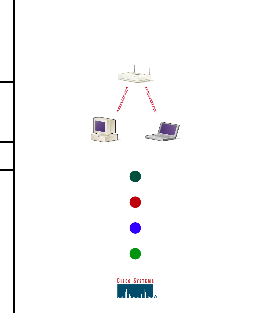
Access Point
PC with PCI
client adapter
Laptop with
PC card
client adapter
1
TAKE OUT WHAT YOU NEED
2
INSERT THE CLIENT ADAPTER
3
INSTALL THE APPROPRIATE DRIVER
4
INSTALL THE CLIENT UTI LITIES
47517
Page 2

Page 3
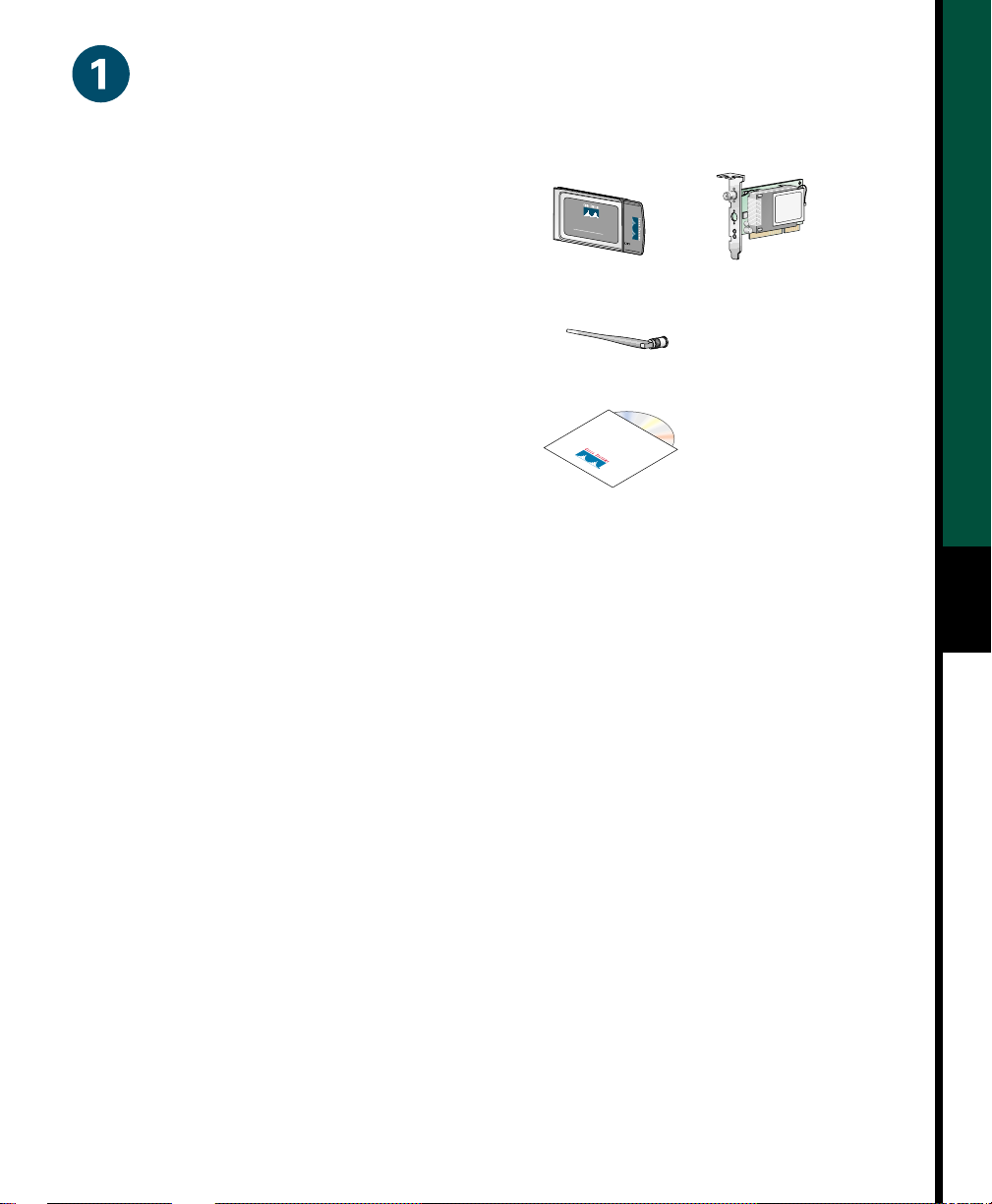
Take Out What You Need
PCI client
adapter
47518
Cisco Aironet PC Card Client Adapter or
Cisco Aironet PCI Client Adapter
PC card
client adapter
CISC
O AIRONET 340
1
1
M
b
S
p
E
s
R
W
I
E
I
S
R
E
L
E
S
S
L
A
N
A
D
A
P
T
E
R
47519
Standard 2-dBi dipole antenna (for PCI client adapter)
Cisco Aironet Series Wirel ess LA N Ada pt er s C D
with software and product documentation
If any item is missing or damaged, contact your Cisco representative or reseller for support. Any
remote antenna and its associate d wiring ar e shipped separa tel y.
Additional Requirements
• A computing device equipped with a Type II or T ype III PC card slot or a desktop personal
computer equipped with an empty PCI expansion slot
1
Note All drivers and supporting software (card and socket services) for the PC card slot
must be loaded and configured.
• A Phillips screwdriver (for PCI client adapte r)
• Windows NT Service Pack 3 or greater if your computer is running Windows N T
• The following information from your system administrator:
— Your wireless client name
— The protocols necessary to bind to the client adapter
— The case-sensitive service set identifier (SSID) for your radio frequency (RF) network
— If you are not connected to a DHCP server , the IP address, broadcast address (if you
are using Linux), subnet mask, and default gateway address of your computer
— The username and password for your netwo rk accou nt
Page 4
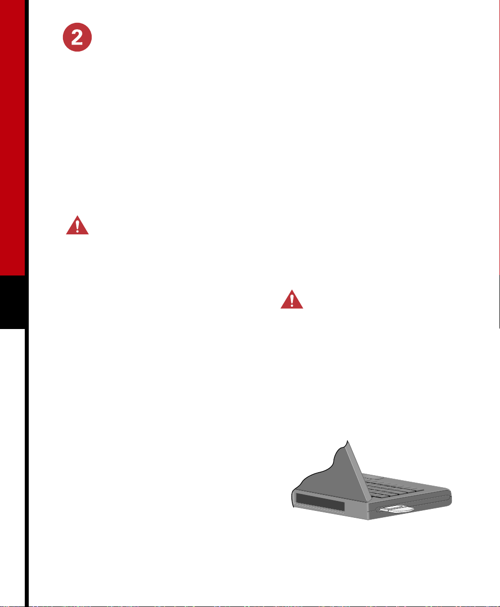
Insert the Cl ie nt A dapter
Note If you are running Windows 95, 98, NT, or 2000 and a Cisco Aironet client adapter was
previously installed on your computer with the 6.10 driver , you must remove this driver before
you can insert your new client adapter and install its more recent driver. Refer to the Cisco
Aironet Wireless LAN Adapters Hardware Installation Guide for information on uninstalling
the 6.10 driver.
Note If you are running Windows 95, you must copy the self-extracting Win95Driver .exe f ile
from the Win95 directory on the CD provided to a floppy disk or a directory on your hard drive
and extract the files before inserting your client adapter. Refer to the Cisco Aironet Wireless
LAN Adapters Hardware Installation Guide for instructions on installing the driver.
Caution These procedures and the physical connections they describe apply generally
to conventional PC card slots and PCI expansion slots. In cases of custom or
nonconventional equipment, be alert to possible differences in PC card slot and PCI
expansion slot configurations.
2
Adapter
Before you begin, examine the PC card
1
client adapter. One end has a dual-row,
68-pin PC card connector. The card is
keyed so it can be inserted only one way
into the PC card slot.
Note The slot is on the left or right side of
the computer, depending on the model.
Turn on the computer before inserting
2
the PC card, unless you are running
Windows NT. For Windows NT, turn
off the computer before inserting the PC
card.
3
4
Insert the PC Card Client
Caution N ev er force th e PC ca r d
into a PC card slot. Forcing it will
damage both the card and the slot.
If the PC card does not insert easily,
remove the card and re-i nse rt it.
Hold the PC card with the Cisco logo
facing up and insert it into the PC card
slot, applying just enough pressure to
make sure it is fully seated.
Proceed to the driver installation
instructions for your operating system.
Page 5

Insert the PCI Client Ada pt er
Antenna
connector
LEDs
Card edge
connector
Standard 2 dBi
dipole antenna
Turn off the PC and all its components.
1
Remove the computer cover.
2
Note On most Pentium PCs, PCI
expansion slots are white. Refer to your PC
documentation for slot identification.
Remove the screw from the top of the
3
CPU back panel above an empty PCI
expansion slot. This screw holds the
metal bracket on the back panel.
Caution Sta t ic elect r ic it y can
damage your client adapter. Before
removing the adapter from the
anti-static packaging, discharge
static by touching a metal part of a
grounded PC.
Press the client adapter into the empty
5
slot until the connector is firmly seated.
Caution Do not force the adapter
into the expansion slot as this could
damage both the adapter and the
slot. If the adapter does not insert
easily, remove the adapter and
re-insert it.
Re-install the screw on the CPU back
6
panel and replac e th e compute r cov er.
Attach the 2-dBi antenna to the
7
adapter’s antenna connector until it is
finger-tight. Do not overtighten.
For optimal reception, position the
8
antenna so it is straight up.
47521
3
Tilt th e adap ter to allow th e antenna
4
connector and LEDs to slip through the
opening in the CPU back panel.
Proceed to the driver installation
9
instructions for your operating system.
Page 6

Install the Appropriate Driver
This section provides installation instructions for the Windows 98 and Windows 2000 drivers.
If your computer is using a Windows 95, Windows NT, Windows Me, Windows CE, Linux, or
Macintosh operating system, refer to the Cisco Air onet Wirel ess L AN Adapt e rs Ha rdware
Installation Guide for driver installation instructions. This guide can be accessed from the CD
provided or from Cisco’s web site at http://www.cisco.com/univercd/cc/td/doc/product/
wireless.
Note The following procedures assume you are installing the driver from the CD provided. If
your computer does not have a CD-ROM drive, download the driver from Cisco’s web site at
http://www.cisco.com/public/sw-center/sw-wireless.shtml. Under “Wireless Software
Products - Cisco Aironet Drivers and Utilities,” select your computer’s operating system
and the appropriate driver.
Windows 9 8 Systems
After you install the client adapter , the system detects it and opens the New Hardware Found
window.
4
When the Add New Hardware Wizard window opens, click Next.
1
When the next dialog box opens, select Se ar ch for the best driver for your device
2
(Recommended) and click Next.
Select CD-ROM drive, deselect all other options, insert the Cisco Aironet Series Wireless
3
LAN Adapters CD into your computer’s CD-ROM drive, and click Next.
When the client adapter driver is displayed, click Next to copy the files.
4
If you are prompted to enter a path to the Windows 98 operating system files, do one of
5
the following:
— If the Windows 98 operating system files are installed on your computer, they should
be in the C:\Windows\Options\Cabs folder . Enter this path in the Copy files from
dialog box and click OK.
— If the system prompts you for the Windows 98 opera ting syst em CD, insert this CD
into your CD-ROM drive, enter D:\WIN98 (where D is your C D - R OM dr ive) in th e
Copy files from dialog box, and click OK.
Page 7

The Add New Hardware Wizard
6
window re-opens indicating that the
installation is complete. Click Finish.
When prompted to restart your
7
computer , remove the CD and click Yes.
When the compute r r estarts,
8
double-click My Computer, Control
Panel, and Network.
Select the Cisco System s wi re less LA N
9
adapter and click Properties.
(c) Select Specify an IP address and
enter the IP address, subnet mask,
and default gateway address of your
computer, which can be obtained
from y our system administrat or.
Click OK.
(d) In th e Network window, click OK.
When prompted to restart your
14
computer, click Yes.
Windows 2000 Systems
In the Properties window, click the
10
Advanced tab.
In the Advanced window , select Client
11
Name a nd enter yo ur computer ’s
unique client name in the Value dialog
box.
Select SSID and enter your RF
12
network’s case-sensitive SSID in the
Value dialog box. Click OK.
If you are not connected to a DHCP
13
server, follow these steps:
(a) Double-click My Comput er,
Control Panel, and Network.
(b) Clic k the Protocols tab and select
TCP/IP and Properties.
After you install the client adapter, the
system detects it and briefly opens the Found
New Hardware window.
The Found New Hardware Wizard window
opens and indicates that the wizard will help
you to install the driver.
Click Next. Another window opens and
1
asks what you want the wizard to do.
Select Search f or a sui table dr iver f or my
2
device (recommended) and click Next.
Select CD-ROM drives, deselec t a ll
3
other options, insert the Cisco Airone t
Series Wireless LAN Adapters CD in to
your computer’s CD-ROM drive, and
click Next.
The wizard finds the installation files on
the CD and displays the search resul ts.
5
When the client adapter driver is
4
displayed, click Next to copy the
required files.
Page 8

When you receive a message indica ting that Windows has finishe d the installation, click
5
Finish.
Remove the CD from your computer’s CD-ROM drive .
6
Double-click My Computer, Control Panel, and System.
7
In the System Properties window, click the Hardw are tab.
8
Click Device Manager.
9
In the Device Manager window, double-click Network Adapters.
10
Right-click th e Cisc o Syste ms wireless LAN a da pter.
11
Click Properties.
12
In the Properties window, click the Advanced tab.
13
In the Advanced window, select Client Name and enter your computer’s unique client name
14
in the Value dialog box.
Select SSID and enter your RF network’s case-sensitive SSID in the Value dialog box. Click
15
6
OK.
If you are not connected to a DHCP server, follow these steps:
16
(a) Double-click My Computer, Control Panel, and Network and Dial-up Connections.
(b) Right-click Local Area Connection.
(c) Click Prope rties, Internet Protocol (TCP/IP), and Properties.
(d) Click Use the following IP address and enter the IP address, subnet mask, and default
gateway address of your computer, whic h can be obtained from your system
administrator. Click OK.
(e) In the Lo cal Area Connection Prop erties window, click OK.
If you are prompted to restart your computer, click Yes.
17
Page 9

Install the Client Utilities
This section provides installation instructions for the client utilities for Windows 95, 98, NT,
2000, and Me. If your computer is using a Windows CE, Linux, or Macintosh operating
system, refer to the Cis co Air onet Wirel ess L AN Adapt e rs Ha rdware Installation Gui de for
information.
After you have installed the appropriate driver for your computer’s operating system, you can
install the Aironet Client Utility (ACU), Link Status Me ter (LSM), and Client Encryption
Manager (CEM) utilities. ACU enables you to configure the client adapter , enable server-based
authentication, and enable the Wired Encryption Privacy (WEP) feature; LSM provides
troubleshooting and status information; and CEM enables you to set one or more WEP keys
for your client adapter.
Close any open Windows programs.
1
Insert the Cisco Aironet Series
2
Wireless LAN Adapters CD into your
computer’s CD-ROM drive.
Select Start > Run and enter the
3
following path (where D is the letter of
your CD-ROM drive): D:\Utilities\
ACU\setup.exe.
At the Welcome scr een, click Next.
4
In the Authentication Method screen,
5
select the server-based authentication
method preferred for wireless network
access in your location and click Next:
— If you select None, server-based
authentication is not enabled for
your client adapter. After the client
utilities are installed, you can elect
not to impl ement any securit y
features, or you can activate some
level of security by using WEP keys.
— If you select LEAP, L EAP is enabl ed
on your client adapter, provided an
EAP-enabled RADIUS server is
running on your network. After
LEAP is enabled and your computer
is rebooted, your client adapter
authenticates to the RADIUS server
using your network logon and
receives a session-based WEP key.
— If you select EAP, EAP is e nabled on
your client adapter, provided an
EAP-enabled RADIUS server is
running on your network. If your
computer is not using an operating
system with built-in EAP support,
this option is not available. After
EAP is enabled and your computer
is rebooted, your client adapter
authenticates to the RADIUS server
using your network logon and
receives a session-based WEP key.
7
Page 10

In the Selec t Com p one n t s sc re en , make sure the clie n t utilities that you wa nt to in s t all are
6
selected and any that you do not want to install are deselected. Click Next.
In the Select Program Folder screen, click Next to al low ic o n s f o r t h e client u t il ities to b e
7
placed in the Cisco Systems, Inc. folder.
In the Setup Complete screen, perform one of the following:
8
— If you selected n o ser v er-based authenti ca t i o n in S t ep 5, select Launc h the Aironet
Client Utility and click Finish. ACU opens so you can configure your client adapter. If
you set a WEP key in CEM and enable WEP using ACU, the WEP key must match the
number and value of the WEP key used by the Access Point.
— If you selected LEAP or EAP server-based authentication in Step 5, select Yes, I want
to restart my computer now, remove the CD from your computer’s CD-ROM drive,
and click Finish. When the computer reboots, e nter your use rname and password at
the network logon screen. The client adapter will be authenticated and assigned a
session-based WE P key, provided your client adapter is configured to associate to an
EAP-enab led A cces s Point.
Refer to the Cisco Aironet Wireless LAN Adapters Software Configuration Guide for
9
8
instructions on how to use each utility.
Note To install and use the client utilities on Windows NT or Windows 2000 systems , you
must log onto the sys t em as a user with administrative privileges. The utilities do not install
or operate correctly for users not lo gged in with admi nistra tive rights.
Safety Information for the Cisco Aironet Wir eless LAN Adapters
The Federal Communications Commission (FCC) with its action in ET Docket 96-8 has
adopted a safety standard for human exposure to RF electromagnetic energy emitted by FCC
certified equipment. Cisco Aironet 340 and 350 series products meet the uncontrolled
environmental limits found in OET-65 and ANSI C95.1, 1991. Proper operation of this radio
according to the instructions found in this manual and the hardware and software guides on
the Cisco Aironet Series Wireless LAN Adapters CD will result in user exposure that is
substantially below the FCC recommended limits.
• Do not touch or move the antenna(s) while the unit is transmitting or receiving.
• Do not hold any component containing a radio such that the antenna is very close to or
touching any exposed parts of the body, especially the face or eyes, while transmitting.
Page 11

• Do not operate the radio or attempt to transmit data unless the antenna is connected;
otherwise, the radio may be damaged.
• Use in specific environments:
— Do not operate a portable transmitter near unshielded blasting caps or in an explosive
environment unless it is a type especially qualified for such use.
— The use of wireless devices in hazardous locations is limited to the constraints posed
by the safety directors of such enviro nme nts.
— The use of wireless devices on airplanes is governed by the Federal Aviation
Administration (FAA).
— The use of wireless devices in hospitals is restricted to the limits set forth by each
hospital.
• Antenna use:
— In order to comply with FCC RF exposure limits, dipole antennas should be located at
a minimum distance of 7.9 inches (20 cm) or more from the body of all persons.
— High-gain, wall-mount, or mast-mount antennas are designed to be professionally
installed and should be located at a minimum distance of 12 inches (30 cm) or more
from the body of all persons. Please contact your professional installer, VAR, or
antenna manufacturer for proper installation requi rem ents .
Warning In order to comply with RF exposure limits established in the ANSI C95.1
standards, it is recommended when using a laptop with a PC card client adapter that
the adapter’s integrated antenna is positioned more than 2 inches (5 cm) from your
body or nearby persons during extended periods of transmitting or operati ng time. If
the antenna is positioned less than 2 inches (5 cm) from the user, it is recomm ended
that the user limit exposure time.
Compliance Inform ation for Cisco Aironet Wireless LAN Adapters
Compliance information for the C isco A ironet Wireless L AN Adapters is provided in t he
Cisco Aironet Wireless LAN Adapters Hardware Inst allati on Guide.
9
Page 12

Corporate Headquarters
Cisco System s, Inc.
170 West Tasman Drive
San Jose, CA 95134-1706
USA
http://www.cisco.com
Tel: 408 526-4000
800 553-NETS (6387)
Fax: 408 526-4100
European Headquarters
Cisco Systems Europe
11, Rue Camille Desmoulins
92782 Issy-les-Moulineaux
Cedex 9
France
http://www-europe.cisco.com
Tel: 33 1 58 04 60 00
Fax: 33 1 58 04 61 00
Americas
Headquarters
Cisco Systems, Inc.
170 West Tasman Drive
San Jose, CA 95134-1706
USA
http://www.cisco.com
Tel: 408 526-7660
Fax: 408 527-0883
Asia Pacific Headquarters
Cisco Systems Australia, Pty., Ltd
Level 17, 99 Walker Street
North Sydney
NSW 2059 Australia
http://www.cisco.com
Tel: +61 2 8448 7100
Fax: +61 2 9957 4350
Cisco Systems has more than 200 offices in the following countries. Addresses, phone numbers, and fax numbers are listed on the
Cisco Connection Online Web site at http://www.cisco.com/go/offices.
Argentina • Australia • Austria • Belgium • Brazil • Bulgaria • Canada • Chile • China • Colombia • Costa Rica • Croatia • Czech
R
epublic • Denmark • Dubai, UAE • Finland • France • Germany • Greece • Hong Kong • Hungary • India • Indonesia • Ireland
Israel • Italy • Japan • Korea • Luxembourg • Malaysia • Mexico • The Netherlands • New Zealand • Norway • Peru • Philippines
Poland • Portugal • Puerto Rico • Romania • Russia • Saudi Arabia • Scotland • Singapore • Slovakia • Slovenia • South Africa • Spain
Sweden • Switzerland • Tai w an • Thailand • Tur k e y • Ukraine • United Kingdom • United States • Venezuela • Vietn am • Zimbabwe
Copyright © 2001, Cisco Systems, Inc. All rights reserved. Access Registrar, AccessPath, Are You Ready, ATM Director, Browse with Me , CCDA, CCDE, CCD P, CCIE, CCNA, CCNP, CCSI,
CD-PAC, CiscoLink, th e Cisc o Net Works logo, Cisco Powered Network logo, Cisco Systems Networking Academy, Fast Step, FireRunner, Follow Me Browsing, FormShare, GigaStack, IGX,
Intelligence in the Optical Core, Internet Quotient, IP/VC, iQ Breakthrough, iQ Expertise, iQ FastTrack, iQ Logo, iQ Readiness Scorecard, Kernel Proxy, MGX, Natural Network Viewer, Network
Registrar, the Networkers l o go , Packet, PIX, Point and Click Internetworking, Policy Builder, RateMUX, ReyMaster, ReyView, ScriptShare, Secure Script, Shop with Me, SlideCast, SMARTnet, SVX,
TrafficDirect or, TransPath, Vlan Dir ecto r, Voice LAN, Wavelength R outer, WebViewer, Workgroup Direct or, and Workgrou p Stac k are trademarks of Cisco Systems, Inc.; Changing the Way We Work,
Live, Play, and Learn, Empowering the Internet Generation, are service marks of Cisco Systems, Inc.; and Aironet, ASIST, BPX, Catalyst, Cisco, the Cisco Certified Internetwo rk Expe rt Lo go, Ci sco IOS,
the Cisco IOS logo, Cisco Pr ess, Cisco Syst ems, Cisco Syst ems Capit al, the Cisco Systems logo , Collision Fre e, Enterprise/S olver, EtherChannel, EtherSwitch, FastHub, FastLink, FastPAD, IOS, IP/TV,
IPX, LightStream, LightSwitch, MICA, NetRanger, Post-Routing, Pre-Routing, Registrar, StrataView Plus, Stratm, SwitchProbe, TeleRouter, and VCO are regi s t ere d trademarks of Cisco Sys t ems, Inc. or
its affiliates in the U.S. and certain other countries.
All other bran ds, nam es, or tradem arks m entio ned in th is docu ment or Web site are the proper ty of thei r resp ectiv e owne rs. The use of the word partner does not imply a partnership relationship
between Cisco and any ot her com pany. (0010R)
Printed in the USA on recycled paper containing 10% postconsumer waste.
DOC-7811532=
78-11532-01
 Loading...