

Page 1

Cisco Aironet Access Point Hardware Installation Guide
340 Series and 350 Series
Corporate Headquarters
Cisco Systems, Inc.
170 West Tasman Drive
San Jose, CA 95134-1706
USA
http://www.cisco.com
Tel: 408 526-4000
800 553-NETS (6387)
Fax: 408 526-4100
Text Part Number: OL-0738-02
Page 2

THE SPECIFICATIONS AND INFORMATION REGARDING THE PRODUCTS IN THIS MANUAL ARE SUBJECT TO CHANGE WITHOUT NOTICE. ALL
STATEMENTS, INFORMATION, AND RECOMMENDATIONS IN THIS MANUAL ARE BELIEVED TO BE ACCURATE BUT ARE PRESENTED WITHOUT
WARRANTY OF ANY KIND, EXPRESS OR IMPLIED. USERS MUST TAKE FULL RESPONSIBILITY FOR THEIR APPLICATION OF ANY PRODUCTS.
THE SOFTWARE LICENSE AND LIMITED WARRANTY FOR THE ACCOMPANYING PRODUCT ARE SET FORTH IN THE INFORMATION PACKET THAT
SHIPPED WITH THE PRODUCT AND ARE INCORPORATED HEREIN BY THIS REFERENCE. IF YOU ARE UNABLE TO LOCATE THE SOFTWARE LICENSE
OR LIMITED WARRANTY, CONTACT YOUR CISCO REPRESENTATIVE FOR A COPY.
The following information is for FCC compliance of Class A devices: This equipment has been tested and found to comply with the limits for a Class A digital device, pursuant
to part 15 of the FCC rules. These limits are designed to provide reasonable protection against harmful interference when the equipment is operated in a commercial
environment. This equipment generates, uses, and can radiate radio-frequency energy and, if not installed and used in accordance with the instruction manual, may cause
harmful interference to radio communications. Operation of this equipment in a residential area is likely to cause harmful interference, in which case users will be required
to correct the interference at their own expense.
The following information is for FCC compliance of Class B devices: The equipment described in this manual generates and may radiate radio-frequency energy. If it is not
installed in accordance with Cisco’s installation instructions, it may cause interference with radio and television reception. This equipment has been tested and found to
comply with the limits for a Class B digital device in accordance with the specifications in part 15 of the FCC rules. These specifications are designed to provide reasonable
protection against such interference in a residential installation. However, there is no guarantee that interference will not occur in a particular installation.
Modifying the equipment without Cisco’s written authorization may result in the equipment no longer complying with FCC requirements for Class A or Class B digital
devices. In that event, your right to use the equipment may be limited by FCC regulations, and you may be required to correct any interference to radio or television
communications at your own expense.
You can determine whether your equipment is causing interference by turning it off. If the interference stops, it was probably caused by the Cisco equipment or one of its
peripheral devices. If the equipment causes interference to radio or television reception, try to correct the interference by using one or more of the following measures:
• Turn the television or radio antenna until the interference stops.
• Move the equipment to one side or the other of the television or radio.
• Move the equipment farther away from the television or radio.
• Plug the equipment into an outlet that is on a different circuit from the television or radio. (That is, make certain the equipment and the television or radio are on circuits
controlled by different circuit breakers or fuses.)
Modifications to this product not authorized by Cisco Systems, Inc. could void the FCC approval and negate your authority to operate the product.
The Cisco implementation of TCP header compression is an adaptation of a program developed by the University of California, Berkeley (UCB) as part of UCB’s public
domain version of the UNIX operating system. All rights reserved. Copyright © 1981, Regents of the University of California.
NOTWITHSTANDING ANY OTHER WARRANTY HEREIN, ALL DOCUMENT FILES AND SOFTWARE OF THESE SUPPLIERS ARE PROVIDED “AS IS” WITH
ALL FAULTS. CISCO AND THE ABOVE-NAMED SUPPLIERS DISCLAIM ALL WARRANTIES, EXPRESSED OR IMPLIED, INCLUDING, WITHOUT
LIMITATION, THOSE OF MERCHANTABILITY, FITNESS FOR A PARTICULAR PURPOSE AND NONINFRINGEMENT OR ARISING FROM A COURSE OF
DEALING, USAGE, OR TRADE PRACTICE.
IN NO EVENT SHALL CISCO OR ITS SUPPLIERS BE LIABLE FOR ANY INDIRECT, SPECIAL, CONSEQUENTIAL, OR INCIDENTAL DAMAGES, INCLUDING,
WITHOUT LIMITATION, LOST PROFITS OR LOSS OR DAMAGE TO DATA ARISING OUT OF THE USE OR INABILITY TO USE THIS MANUAL, EVEN IF CISCO
OR ITS SUPPLIERS HAVE BEEN ADVISED OF THE POSSIBILITY OF SUCH DAMAGES.
CCSP, the Cisco Square Bridge logo, Cisco Unity, Follow Me Browsing, FormShare, and StackWise are trademarks of Cisco Systems, Inc.; Changing the Way We Work, Live,
Play, and Learn, and iQuick Study are service marks of Cisco Systems, Inc.; and Aironet, ASIST, BPX, Catalyst, CCDA, CCDP, CCIE, CCIP, CCNA, CCNP, Cisco, the Cisco
Certified Internetwork Expert logo, Cisco IOS, Cisco Press, Cisco Systems, Cisco Systems Capital, the Cisco Systems logo, Empowering the Internet Generation,
Enterprise/Solver, EtherChannel, EtherFast, EtherSwitch, Fast Step, GigaDrive, GigaStack, HomeLink, Internet Quotient, IOS, IP/TV, iQ Expertise, the iQ logo, iQ Net Readiness
Scorecard, LightStream, Linksys, MeetingPlace, MGX, the Networkers logo, Networking Academy, Network Registrar, Pac ket , PIX, Post-Routing, Pre-Routing, ProConnect,
RateMUX, Registrar, ScriptShare, SlideCast, SMARTnet, StrataView Plus, SwitchProbe, TeleRouter, The Fastest Way to Increase Your Internet Quotient, TransPath, and VCO are
registered trademarks of Cisco Systems, Inc. and/or its affiliates in the United States and certain other countries.
All other trademarks mentioned in this document or Website are the property of their respective owners. The use of the word partner does not imply a partnership relationship
between Cisco and any other company. (0406R)
Cisco Aironet Access Point Hardware Installation Guide
Copyright ©2004 Cisco Systems, Inc. All rights reserved.
Page 3

Preface vii
Objectives vii
Audience vii
Organization vii
Conventions viii
Related Publications viii
Obtaining Documentation ix
Cisco.com ix
Ordering Documentation ix
Documentation Feedback ix
Obtaining Technical Assistance x
Cisco TAC Website x
Opening a TAC Case x
TAC Case Priority Definitions x
CONTENTS
CHAPTER
CHAPTER
Obtaining Additional Publications and Information xi
1 Overview 1-1
Key Features 1-2
Inline Power 1-2
Omni-Directional Antennas 1-2
Ethernet and Serial Ports 1-3
Ethernet Port 1-3
Serial Port 1-3
Metal Enclosure 1-3
Indicators 1-4
Network Configuration Examples 1-5
Root Unit on a Wired LAN 1-5
Repeater Unit That Extends Wireless Range 1-6
Central Unit in an All-Wireless Network 1-7
Access Point Specifications 1-8
2 Installation 2-1
OL-0738-02
Cautions and Warnings 2-2
Cisco Aironet Access Point Hardware Installation Guide
iii
Page 4

Contents
Installation Guidelines 2-3
Basic Guidelines 2-3
Special Considerations 2-3
Coverage Options 2-3
Minimal Overlap Coverage Option 2-4
Multiple Overlapping Networks Coverage Option 2-4
Heavy Overlap Coverage Option 2-5
Site Surveys 2-5
Unpacking the Access Point 2-6
Package Contents 2-6
Connecting the Ethernet and Power Cables 2-7
Connecting Cables on 340 Series Access Points 2-7
Connecting Cables on 350 Series Access Points 2-8
CHAPTER
CHAPTER
3 Basic Configuration 3-1
Before You Start 3-2
Summary of Configuration Steps 3-2
Using the IP Setup Utility 3-2
Obtaining and Installing IPSU 3-3
Finding the Access Point’s IP Address 3-3
Setting the Access Point’s IP Address and SSID 3-4
Entering Basic Settings 3-5
Using an Internet Browser 3-5
Using a Terminal Emulator 3-7
Selecting Pages and Settings 3-7
Applying Changes to the Configuration 3-7
Assigning Basic Settings 3-7
Default Basic Settings 3-10
4 Troubleshooting 4-1
Checking the Top Panel Indicators 4-2
Checking Basic Settings 4-3
SSID 4-3
WEP Keys 4-3
iv
Resetting to the Default Configuration 4-4
Steps for Firmware Versions 11.07 or Later 4-4
Steps for Firmware Versions 11.06 or Earlier 4-5
Determining the Boot-Block Version 4-5
Cisco Aironet Access Point Hardware Installation Guide
OL-0738-02
Page 5

Reconfiguration Steps for Boot Block Version 1.01 or Earlier 4-6
Reconfiguration Steps for Boot Block Version 1.02 or Later 4-7
Contents
APPENDIX
APPENDIX
A Translated Safety Warnings A-1
Explosive Device Proximity Warning A-2
Lightning Activity Warning A-3
Installation Warning A-3
Circuit Breaker (15A) Warning A-4
Power Injector Warning A-6
B Declarations of Conformity and Regulatory Information B-1
Manufacturers Federal Communication Commission Declaration of Conformity Statement B-2
Department of Communications – Canada B-3
Canadian Compliance Statement B-3
European Community, Switzerland, Norway, Iceland, and Liechtenstein B-4
Declaration of Conformity with Regard to the R&TTE Directive 1999/5/EC B-4
Declaration of Conformity for RF Exposure B-5
Guidelines for Operating Cisco Aironet Access Points and Bridges in Japan B-6
Japanese Translation B-6
English Translation B-6
I
NDEX
Declaration of Conformity Statements B-7
Declaration of Conformity Statement for European Union Countries B-7
OL-0738-02
Cisco Aironet Access Point Hardware Installation Guide
v
Page 6

Contents
vi
Cisco Aironet Access Point Hardware Installation Guide
OL-0738-02
Page 7

Objectives
Preface
This section describes the objectives, audience, organization, and conventions of the Cisco Aironet
Access Point Hardware Installation Guide.
This publication explains the steps for initial setup and configuration of the access point. This
publication also provides troubleshooting information and detailed specifications.
Audience
This publication is for the person installing and configuring a Cisco Aironet Access Point for the first
time. The installer should be familiar with network structures, terms, and concepts.
Organization
This guide contains the following sections:
Chapter 1, “Overview,” describes the features and specifications of access points.
Chapter 2, “Installation,” provides basic installation instructions.
Chapter 3, “Basic Configuration,” describes how to enter basic configuration settings.
Chapter 4, “Troubleshooting,” provides solutions to potential problems encountered during setup.
Appendix A, “Translated Safety Warnings,” lists translations of the safety warnings in this publication.
Appendix B, “Declarations of Conformity and Regulatory Information,” describes the regulatory
conventions to which the access point conforms and provides guidelines for operating access points in
Japan.
OL-0738-02
Cisco Aironet Access Point Hardware Installation Guide
vii
Page 8
Conventions
Conventions
This publication uses the following conventions to convey instructions and information:
Note Means reader take note. Notes contain helpful suggestions or references to materials not contained in
this manual.
Caution Means reader be careful. In this situation, you might do something that could result in equipment
damage or loss of data.
Preface
• Commands and keywords are in boldface type.
Warning
The warning symbol means danger.
work on any equipment, be aware of the hazards involved with electrical circuitry and be familiar
with standard practices for preventing accidents. To see translations of the warnings that appear
in this publication, refer to Appendix A in this manual.
Related Publications
For more information about access points and related products, refer to the following publications:
• Quick Start Guide: Cisco Aironet Access Points describes how to attach cables, power on, and assign
an IP address and default gateway for the access point.
• Cisco Aironet Access Point Software Configuration Guide describes the access point’s management
system and explains how to configure the access point.
• Release Notes for Cisco Aironet Access Points describes features and caveats for access points
running firmware release 10.14.
• Cisco Secure Access Control Server for Windows 2000/NT Servers Version 2.6 User Guide provides
complete instructions for using Cisco Secure ACS, including steps for configuring Cisco Secure
ACS to support access points.
• Quick Start Guide: Cisco Aironet Wireless LAN Adapters describes how to install and configure PC
and PCI card client adapters for use in a wireless LAN.
• Cisco Aironet Wireless LAN Adapters Hardware Installation Guide provides hardware features,
physical and performance characteristics, and installation instructions for PC and PCI card client
adapters.
• Cisco Aironet Wireless LAN Adapters Software Configuration Guide provides instructions for
installing and using the wireless client adapter utilities.
You are in a situation that could cause bodily injury. Before you
viii
Cisco Aironet Access Point Hardware Installation Guide
OL-0738-02
Page 9

Preface
Obtaining Documentation
Cisco documentation and additional literature are available on Cisco.com. Cisco also provides several
ways to obtain technical assistance and other technical resources. These sections explain how to obtain
technical information from Cisco Systems.
Cisco.com
You can access the most current Cisco documentation on the World Wide Web at this URL:
http://www.cisco.com/univercd/home/home.htm
You can access the Cisco website at this URL:
http://www.cisco.com
International Cisco websites can be accessed from this URL:
http://www.cisco.com/public/countries_languages.shtml
Obtaining Documentation
Ordering Documentation
You can find instructions for ordering documentation at this URL:
http://www.cisco.com/univercd/cc/td/doc/es_inpck/pdi.htm
You can order Cisco documentation in these ways:
• Registered Cisco.com users (Cisco direct customers) can order Cisco product documentation from
the Ordering tool:
http://www.cisco.com/en/US/partner/ordering/index.shtml
• Nonregistered Cisco.com users can order documentation through a local account representative by
calling Cisco Systems Corporate Headquarters (California, USA) at 408 526-7208 or, elsewhere in
North America, by calling 800 553-NETS (6387).
Documentation Feedback
You can submit e-mail comments about technical documentation to bug-doc@cisco.com.
You can submit comments by using the response card (if present) behind the front cover of your
document or by writing to the following address:
Cisco Systems
Attn: Customer Document Ordering
170 West Tasman Drive
San Jose, CA 95134-9883
OL-0738-02
We appreciate your comments.
Cisco Aironet Access Point Hardware Installation Guide
ix
Page 10

Obtaining Technical Assistance
Obtaining Technical Assistance
For all customers, partners, resellers, and distributors who hold valid Cisco service contracts, the Cisco
Technical Assistance Center (TAC) provides 24-hour-a-day, award-winning technical support services,
online and over the phone. Cisco.com features the Cisco TAC website as an online starting point for
technical assistance. If you do not hold a valid Cisco service contract, please contact your reseller.
Cisco TAC Website
The Cisco TAC website provides online documents and tools for troubleshooting and resolving technical
issues with Cisco products and technologies. The Cisco TAC website is available 24 hours a day, 365
days a year. The Cisco TAC website is located at this URL:
http://www.cisco.com/tac
Accessing all the tools on the Cisco TAC website requires a Cisco.com user ID and password. If you
have a valid service contract but do not have a login ID or password, register at this URL:
http://tools.cisco.com/RPF/register/register.do
Preface
Opening a TAC Case
Using the online TAC Case Open Tool is the fastest way to open P3 and P4 cases. (P3 and P4 cases are
those in which your network is minimally impaired or for which you require product information.) After
you describe your situation, the TAC Case Open Tool automatically recommends resources for an
immediate solution. If your issue is not resolved using the recommended resources, your case will be
assigned to a Cisco TAC engineer. The online TAC Case Open Tool is located at this URL:
http://www.cisco.com/tac/caseopen
For P1 or P2 cases (P1 and P2 cases are those in which your production network is down or severely
degraded) or if you do not have Internet access, contact Cisco TAC by telephone. Cisco TAC engineers
are assigned immediately to P1 and P2 cases to help keep your business operations running smoothly.
To open a case by telephone, use one of the following numbers:
Asia-Pacific: +61 2 8446 7411 (Australia: 1 800 805 227)
EMEA: +32 2 704 55 55
USA: 1 800 553-2447
For a complete listing of Cisco TAC contacts, go to this URL:
http://www.cisco.com/warp/public/687/Directory/DirTAC.shtml
TAC Case Priority Definitions
To ensure that all cases are reported in a standard format, Cisco has established case priority definitions.
Priority 1 (P1)—Your network is “down” or there is a critical impact to your business operations. You
and Cisco will commit all necessary resources around the clock to resolve the situation.
Priority 2 (P2)—Operation of an existing network is severely degraded, or significant aspects of your
business operation are negatively affected by inadequate performance of Cisco products. You and Cisco
will commit full-time resources during normal business hours to resolve the situation.
Cisco Aironet Access Point Hardware Installation Guide
x
OL-0738-02
Page 11

Preface
Obtaining Additional Publications and Information
Priority 3 (P3)—Operational performance of your network is impaired, but most business operations
remain functional. You and Cisco will commit resources during normal business hours to restore service
to satisfactory levels.
Priority 4 (P4)—You require information or assistance with Cisco product capabilities, installation, or
configuration. There is little or no effect on your business operations.
Obtaining Additional Publications and Information
Information about Cisco products, technologies, and network solutions is available from various online
and printed sources.
• Cisco Marketplace provides a variety of Cisco books, reference guides, and logo merchandise. Go
to this URL to visit the company store:
http://www.cisco.com/go/marketplace/
• The Cisco Product Catalog describes the networking products offered by Cisco Systems, as well as
ordering and customer support services. Access the Cisco Product Catalog at this URL:
http://cisco.com/univercd/cc/td/doc/pcat/
• Cisco Press publishes a wide range of general networking, training and certification titles. Both new
and experienced users will benefit from these publications. For current Cisco Press titles and other
information, go to Cisco Press online at this URL:
http://www.ciscopress.com
• Pack et magazine is the Cisco quarterly publication that provides the latest networking trends,
technology breakthroughs, and Cisco products and solutions to help industry professionals get the
most from their networking investment. Included are networking deployment and troubleshooting
tips, configuration examples, customer case studies, tutorials and training, certification information,
and links to numerous in-depth online resources. You can access Packet magazine at this URL:
http://www.cisco.com/packet
• iQ Magazine is the Cisco bimonthly publication that delivers the latest information about Internet
business strategies for executives. You can access iQ Magazine at this URL:
http://www.cisco.com/go/iqmagazine
• Internet Protocol Journal is a quarterly journal published by Cisco Systems for engineering
professionals involved in designing, developing, and operating public and private internets and
intranets. You can access the Internet Protocol Journal at this URL:
http://www.cisco.com/ipj
• Training—Cisco offers world-class networking training. Current offerings in network training are
listed at this URL:
http://www.cisco.com/en/US/learning/index.html
OL-0738-02
Cisco Aironet Access Point Hardware Installation Guide
xi
Page 12

Obtaining Additional Publications and Information
Preface
xii
Cisco Aironet Access Point Hardware Installation Guide
OL-0738-02
Page 13

CHA P TER
1
Overview
The Cisco Aironet access point is a wireless LAN transceiver that serves as the center point of a
stand-alone wireless network or as the connection point between wireless and wired networks. In large
installations, wireless users within radio range of an access point can roam throughout a facility while
maintaining uninterrupted access to the network.
This chapter provides information on the following topics:
• Key features
• Network configuration examples
• Access point specifications
OL-0738-02
Cisco Aironet Access Point Hardware Installation Guide
1-1
Page 14
Key Features
Key Features
This section describes the key features of the access point:
• Inline power
• Omni-directional antennas
• Ethernet and serial ports
• Indicators
• Industrial temperature range and UL 2043 rating for 350 series metal case access point
Inline Power
Cisco Aironet 350 series access points receive power through the Ethernet cable, so you do not need to
run a separate power cord to the access point. Plug the Ethernet cable into the Ethernet port on the back
of the access point and plug the other end into one of three possible power sources:
• A Cisco Aironet power injector
• A switch with inline power, such as the Cisco Catalyst 3524-PWR-XL switch
• A power patch panel, such as the Cisco Catalyst Inline Power Patch Panel
Chapter 1 Overview
Note Cisco Aironet 340 series access points rely on a separate power supply plugged into the power port on
the back of the access point.
Caution Cisco Aironet power injectors are designed for use with 350 series access points and bridges only. Using
the power injector with other Ethernet-ready devices can damage the equipment.
Caution Cisco Aironet Power Injectors are not rated for operation in a building’s environmental air space, such
as above suspended ceilings.
Caution The operational voltage range for Cisco Aironet 350 series access points and bridges is 24 to 60 VDC.
Higher voltage can damage the equipment.
Omni-Directional Antennas
The access point’s omni-directional, 2.2 dBi antennas provide diversity coverage for your wireless LAN
area. Diversity coverage helps maintain a clear radio signal between the access point and wireless client
devices. Just as you can improve signal clarity on your car radio at a stoplight by creeping ahead a few
inches, the access point can improve signal quality by choosing the antenna that is receiving the best
signal from a client device.
Some access points models are equipped with dual reverse-polarity TNC connectors that you can use to
connect to your own antennas for special applications.
1-2
Cisco Aironet Access Point Hardware Installation Guide
OL-0738-02
Page 15

Chapter 1 Overview
Ethernet and Serial Ports
Ethernet Port
The access point’s Ethernet port accepts an RJ-45 connector, linking the access point to your 10/100
Ethernet LAN. The 350 series access point receives power through the Ethernet cable from a switch with
inline power, from a power patch panel, or from the access point’s power injector.
Serial Port
The access point’s serial port provides console access to the access point’s management system. Use a
nine-pin, straight-through, male-to-female serial cable to connect your computer’s COM 1 or COM 2
port to the access point’s serial port. Assign the following port settings to a terminal emulator to open
the management system pages: 9600 baud, 8 data bits, No parity, 1 stop bit, and Xon/Xoff flow control.
Metal Enclosure
Key Features
The 350 series metal case access point contains a metal enclosure having adequate fire resistance and
low smoke-producing characteristics suitable for operation in a building’s environmental air space in
accordance with Section 300-22(c) of the NEC. The 350 series metal case access point also supports an
industrial temperature operating range.
OL-0738-02
Cisco Aironet Access Point Hardware Installation Guide
1-3
Page 16
Key Features
Indicators
Chapter 1 Overview
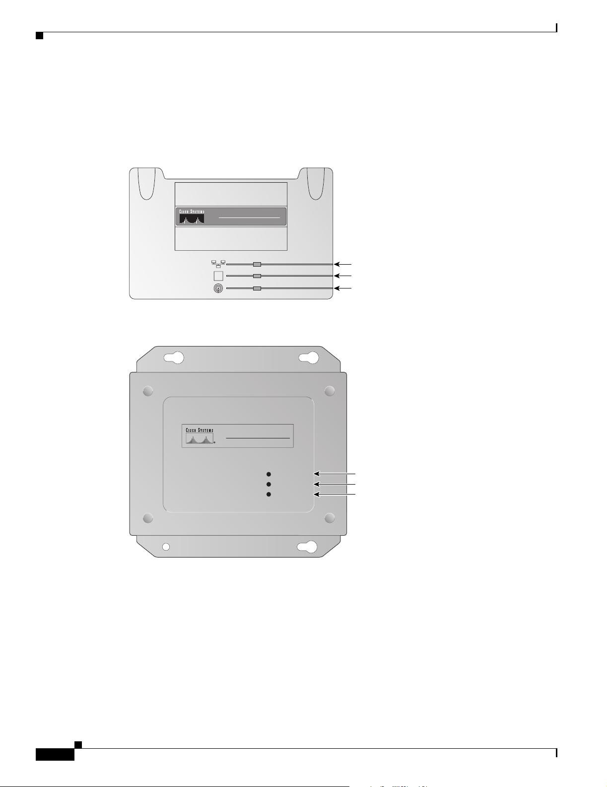
The three indicators on top of the access point report Ethernet activity, association status, and radio
activity. The indicators are labeled in Figure 1-1 and Figure 1-2.
Figure 1-1 Indicators on the 340 and 350 Series Access Point
CISCO AIRONET 350
WIRELESS ACCESS POINT
SERIES
Ethernet
S
Status
Radio
49075
Figure 1-2 Indicators on the 350 Series Metal Case Access Point
CISCO AIRONET 350
WIRELESS ACCESS POINT
SERIES
ETHERNET ACTIVITY
ASSOCIATION STATUS
RADIO ACTIVITY
Ethernet
Status
Radio
1-4
The Ethernet indicator signals Ethernet traffic on the wired LAN. This indicator blinks green when
•
a packet is received or transmitted over the Ethernet infrastructure. The indicator blinks red when
the Ethernet cable is not connected.
• The association status indicator signals operational status. Blinking green indicates that the access
point is operating normally but is not associated with any wireless client devices. Steady green
indicates that the access point is associated with at least one wireless client device.
• The radio indicator blinks green to indicate radio traffic activity. The light is normally off, but it
blinks green whenever a packet is received or transmitted over the access point radio.
Cisco Aironet Access Point Hardware Installation Guide
60511
OL-0738-02
Page 17
Chapter 1 Overview
Network Configuration Examples
This section describes the access point’s role in three common wireless network configurations. The
access point’s default configuration is as a root unit on a wired LAN. The other two possible roles,
repeater unit and central unit in an all-wireless network, require specific changes to the default
configuration.
Root Unit on a Wired LAN
An access point connected directly to a wired LAN provides a connection point for wireless users. If
more than one access point is connected to the LAN, users can roam from one area of a facility to another
without losing their connection to the network. As users move out of range of one access point, they
automatically connect to the network (associate) through another access point. The roaming process is
seamless and transparent to the user. Figure 1-3 shows access points acting as root units on a wired LAN.
Figure 1-3 Access Points as Root Units on a Wired LAN
Access Point
(Root Unit)
Wired LAN
Network Configuration Examples
Access Point
(Root Unit)
OL-0738-02
45835
Cisco Aironet Access Point Hardware Installation Guide
1-5
Page 18
Network Configuration Examples
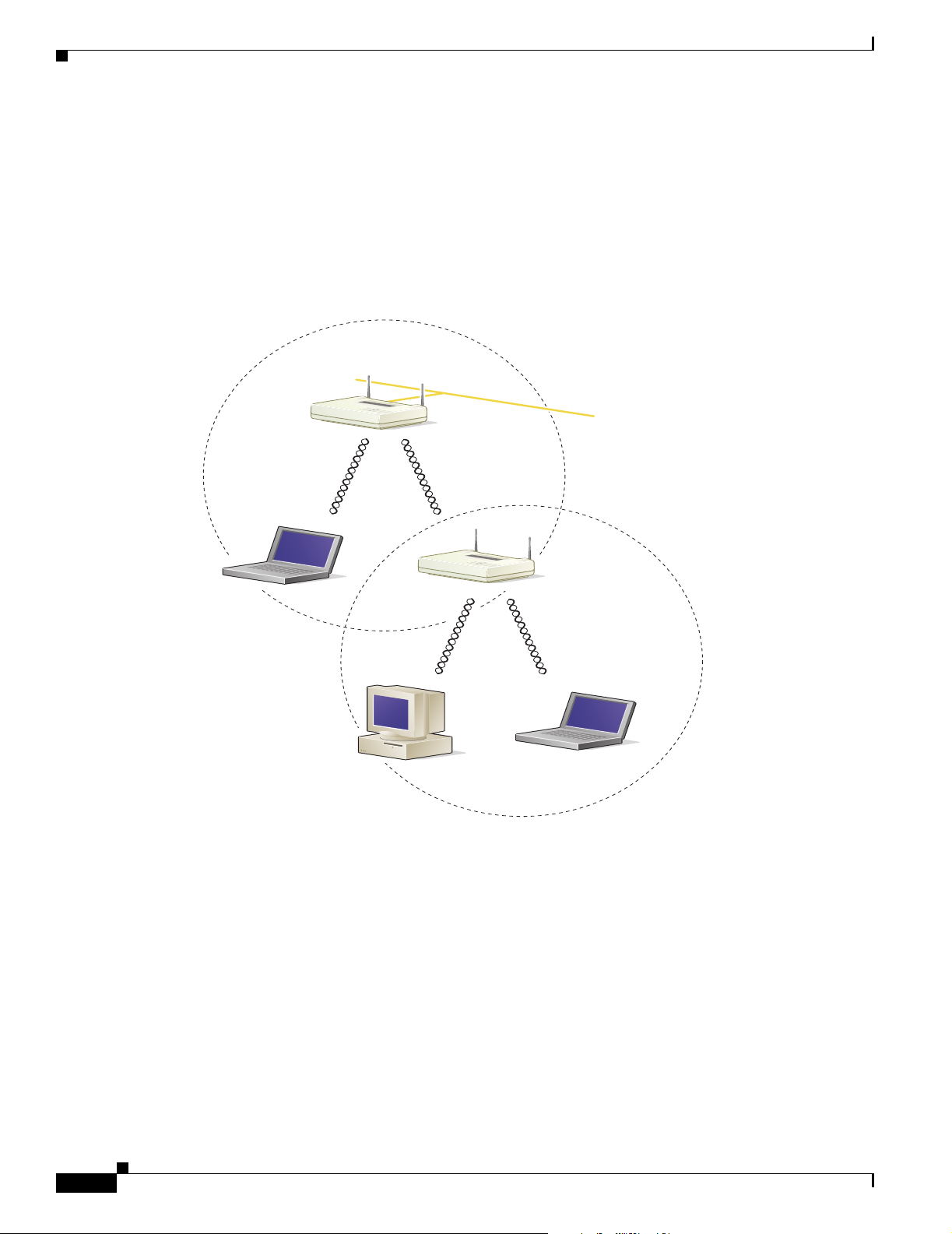
Repeater Unit That Extends Wireless Range
An access point can be configured as a stand-alone repeater to extend the range of your infrastructure or
to overcome an obstacle that blocks radio communication. The repeater forwards traffic between
wireless users and the wired LAN by sending packets to either another repeater or to an access point
connected to the wired LAN. The data is sent through the route that provides the greatest performance
for the client. Figure 1-4 shows an access point acting as a repeater.
Figure 1-4 Access Point as Repeater
Access Point
(Root Unit)
Chapter 1 Overview
Wired LAN
Access Point
(Repeater)
45836
1-6
Cisco Aironet Access Point Hardware Installation Guide
OL-0738-02
Page 19
Chapter 1 Overview
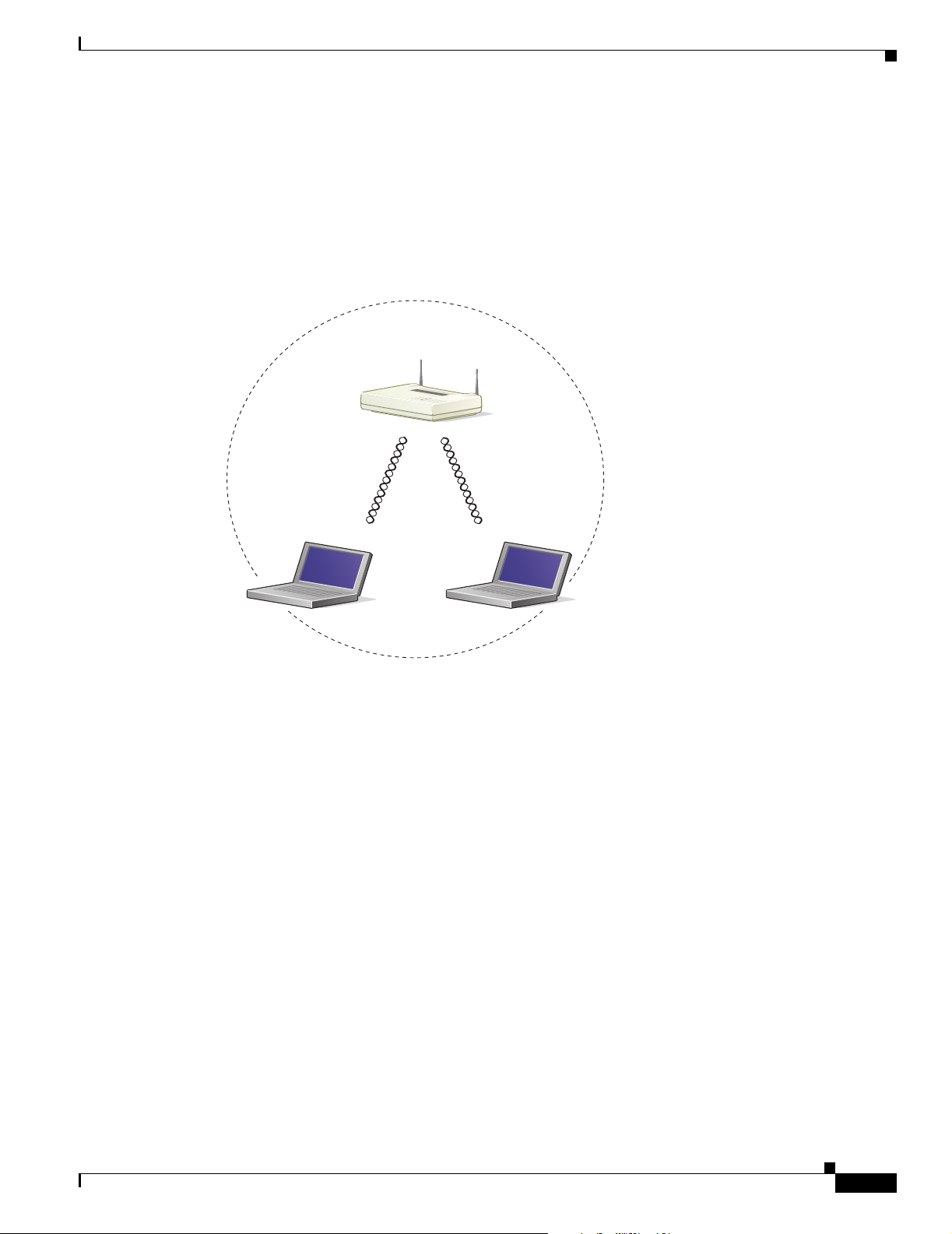
Central Unit in an All-Wireless Network
In an all-wireless network, an access point acts as a stand-alone root unit. The access point is not
attached to a wired LAN; it functions as a hub linking all stations together. The access point serves as
the focal point for communications, increasing the communication range of wireless users. Figure 1-5
shows an access point in an all-wireless network.
Figure 1-5 Access Point as Central Unit in All-Wireless Network
Access Point
(Root Unit)
Network Configuration Examples
45834
OL-0738-02
Cisco Aironet Access Point Hardware Installation Guide
1-7
Page 20

Access Point Specifications
Access Point Specifications
Table 1-1 lists specifications for the access point.
Table 1-1 Access Point Specifications
Category Specification
Physical
Size 6.30 in. (16 cm) W x 4.72 in. (12 cm) D x 1.45 in. (3.7 cm) H
Status indicators Three indicators on the top panel: Ethernet traffic, status, and
Connectors On the back panel: An RJ-45 jack for 10/100 Ethernet
Voltage range 24 to 60 VDC (regulated 5 VDC for 340 series only)
Operating temperature range 32 to 122
Weight Less than 1 lb (0.45 kg) for 340 and 350 series
Chapter 1 Overview
radio traffic
connections; a nine-pin serial connector; a power connector
(plug-in AC adapter) for a regulated 5V input (340 series
only)
o
F (0 to 50oC) for 340 and 350 series
–4 to 131
32 to 104
o
F (–20 to 55oC) for 350 series metal case
o
F (0 to 40oC) for power injectors
1.43 lbs (0.64 kg) for 350 series metal case
Radio
Power output 100, 50, 30, 20, 5, or 1 mW for 350 series
30, 20, 5, or 1 mW for 340 series
(Depending on the regulatory domain in which the access point
is installed)
Frequency 2.400 to 2.497 GHz (Depending on the regulatory domain in
which the access point is installed)
Range Indoor:
150 ft at 11 Mbps (100 ft for 340 series only)
350 ft at 1 Mbps (300 ft for 340 series only)
Outdoor:
800 ft at 11 Mbps (400 ft for 340 series only)
2000 ft at 1 Mbps (1500 ft for 340 series only)
Modulation Direct Sequence Spread Spectrum
Data rates 1, 2, 5.5, and 11 Mbps
1-8
Cisco Aironet Access Point Hardware Installation Guide
OL-0738-02
Page 21

Chapter 1 Overview
Access Point Specifications
Table 1-1 Access Point Specifications (continued)
Category Specification
Antenna Two captured 2.2 dBi gain antennas or a diversity system with
two reverse-TNC connectors (antennas for this model are sold
separately). Some models in the 340 series have one 2.2 dBi
gain antenna.
Compliance Operates license-free under FCC Part 15 and complies as a
Class B computing device. Complies with DOC regulations.
Complies with the following: ETS 300.328, FTZ 2100, MPT
1349, FCC Part 15.107 and 15.109 Class B, ICES-003 Class
B (Canada), CISPR 22 Class B, AS/NZS 3548 Class B, VCCI
Class B, EN 50082-1, UL1950, CSA 22.2 No. 950, EN 60950,
IEC 60950, VCCI, and others (see Appendix B).
350 series metal case access point complies with UL 2043 for
products installed in air handling spaces, such as above
suspended ceilings.
Caution Cisco Aironet Power Injectors are not
rated for UL 2043 and should not be
placed in air handling spaces, such as
above suspended ceilings.
OL-0738-02
Cisco Aironet Access Point Hardware Installation Guide
1-9
Page 22

Access Point Specifications
Chapter 1 Overview
1-10
Cisco Aironet Access Point Hardware Installation Guide
OL-0738-02
Page 23

CHA P TER
Installation
This chapter describes the setup of the access point and includes the following sections:
• Cautions and Warnings
• Installation Guidelines
• Unpacking the Access Point
• Connecting the Ethernet and Power Cables
2
OL-0738-02
Cisco Aironet Access Point Hardware Installation Guide
2-1
Page 24

Cautions and Warnings
Cautions and Warnings
Translated versions of the following safety warnings are provided in Appendix A, “Translated Safety
Warnings.”
Note The FCC, with its action in ET Docket 96-8, has adopted a safety standard for human exposure to
radiated frequency (RF) electromagnetic energy emitted by FCC-certified equipment. Cisco Aironet
products meet the uncontrolled environmental limits found in OET-65 and ANSI C95.1, 1991. Proper
operation of this radio device according to the instructions in this publication will result in user exposure
substantially below the FCC recommended limits.
Caution Cisco Aironet power injectors are designed for use with 350 series access points and bridges only. Using
the power injector with other Ethernet-ready devices can damage the equipment.
Caution The operational voltage range for Cisco Aironet 350 series access points and bridges is 24 to 60 volts.
Higher voltage can damage the equipment.
Chapter 2 Installation
Caution Cisco Aironet Power Injectors are not rated for operation in a building’s environmental air space, such
as above suspended ceilings.
Warning
Warning
Warning
Warning
Do not operate your wireless network device near unshielded blasting caps or in an explosive
environment unless the device has been modified to be especially qualified for such use.
Do not work on the system or connect or disconnect cables during periods of lightning activity.
Read the installation instructions before you connect the system to its power source.
This product relies on the building's installation for short-circuit (overcurrent) protection. Ensure that
a fuse or circuit breaker no larger than 120 VAC, 15A U.S. (240 VAC, 10A international) is used on the
phase conductors (all current-carrying conductors).
2-2
Cisco Aironet Access Point Hardware Installation Guide
OL-0738-02
Page 25

Chapter 2 Installation
Installation Guidelines
This section describes things to keep in mind when installing your access point. Sections include:
• Basic Guidelines
• Special Considerations
• Coverage Options
• Site Surveys
Basic Guidelines
Because the access point is a radio device, it is susceptible to common causes of interference that can
reduce throughput and range. Follow these basic guidelines to ensure the best possible performance:
• Install the access point in an area where large steel structures such as shelving units, bookcases, and
filing cabinets do not obstruct radio signals to and from the access point.
• Install the access point away from microwave ovens. Microwave ovens operate on the same
frequency as the access point and can cause signal interference.
Installation Guidelines
Special Considerations
The 350 series metal case access point provides adequate fire resistance and low smoke-producing
characteristics suitable for operation in a building’s environmental air space, such as above suspended
ceilings. This access point is intended for indoor use and can be used in environments where the temperature
ranges from -4 to 131
Caution Cisco Aironet Power Injectors are not rated for operation in a building’s environmental air space, such
as above suspended ceilings.
Coverage Options
The network architecture options of wireless stations and access points provide for a variety of coverage
alternatives and flexibility. The network can be designed to provide a wide coverage area with minimal
overlap or a narrow coverage area with heavy overlap. A narrow coverage area with heavy overlap
improves network performance and protection against downtime if a component fails.
o
F (-20 to 55oC).
OL-0738-02
Cisco Aironet Access Point Hardware Installation Guide
2-3
Page 26

Installation Guidelines
Minimal Overlap Coverage Option
By arranging the access points so that the overlap in a coverage area is minimized, a large area can be
covered with minimal cost (see Figure 2-1). The total bandwidth available to each wireless client device
depends on the amount of data each mobile station needs to transfer and the number of stations located
in each cell. Seamless roaming is supported as a client device moves in and out of range of each access
point, thereby maintaining a constant connection to the wired LAN. Each device in the radio network
must be configured with the same SSID to provide roaming capability.
Figure 2-1 Minimal Overlap Coverage Option
Chapter 2 Installation
Wired LAN
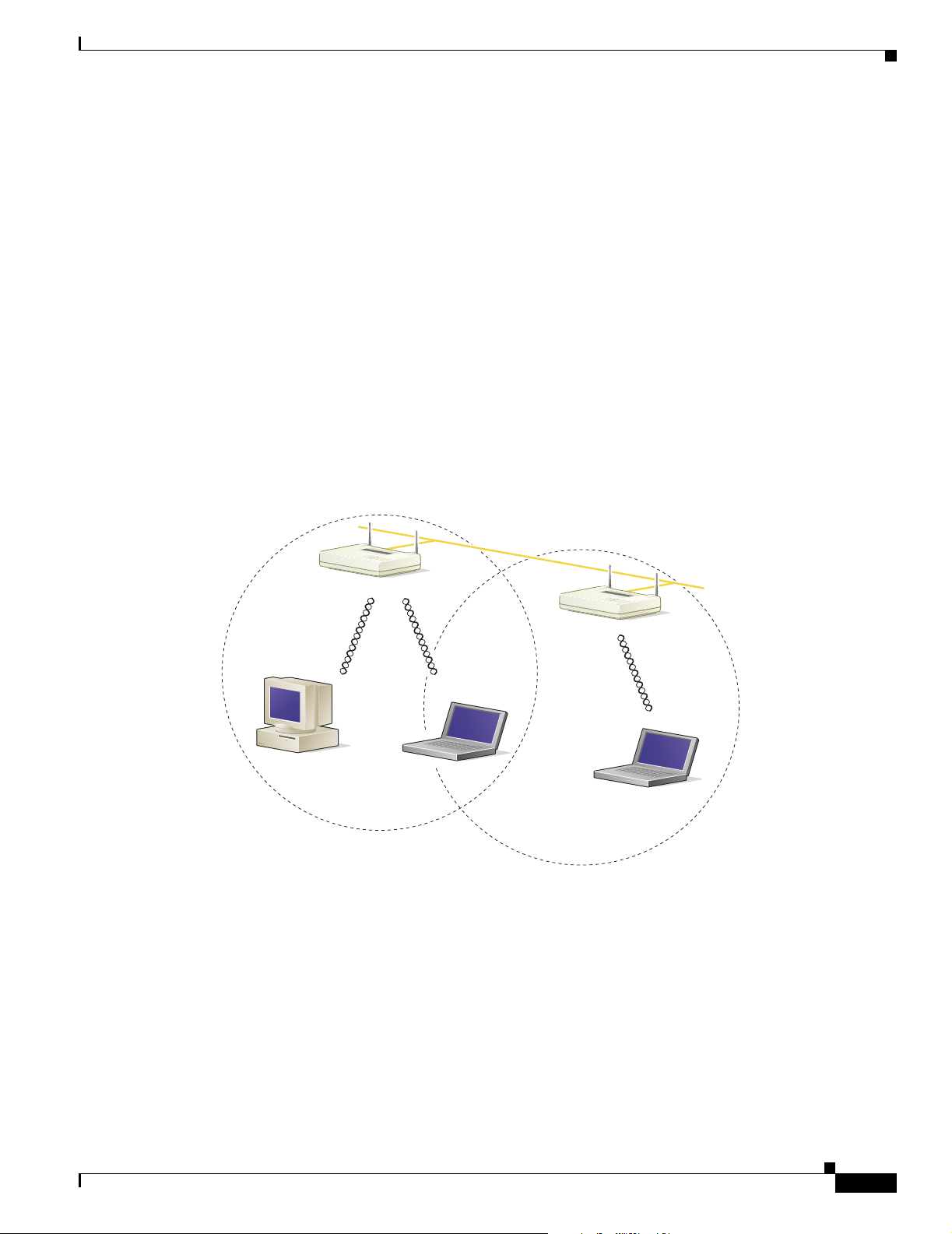
Multiple Overlapping Networks Coverage Option
Multiple networks can operate in the same vicinity (see Figure 2-2). The architecture provides multiple
channels that can exist in the same area with virtually no interference to each other. In this mode, each
system must be configured with different SSIDs and different channels, which may (depending on
configurations) prevent clients from roaming to access points of a different wireless network.
Figure 2-2 Multiple Overlapping Networks Coverage Option
Wired LAN 2
Wired LAN 1
46223
2-4
46225
Cisco Aironet Access Point Hardware Installation Guide
OL-0738-02
Page 27

Chapter 2 Installation
Heavy Overlap Coverage Option
By arranging the access points so the overlap in coverage area is nearly maximized, a large number of
mobile stations can be supported in the same wireless infrastructure (see Figure 2-3). However, devices
in overlapping coverage areas on the same frequency will detect adjacent cell traffic and delay
transmissions that would cause collisions. This configuration reduces the aggregate radio system
throughput. Heavy cell overlap is not recommended for maximum system throughput.
Because of the redundancy in coverage overlap, network access is not lost if an access point fails. Upon
failure of the access point, the station automatically roams to an operational access point. With this
architecture, each device in the RF network must be configured with the same SSID to provide the
roaming capability.
Figure 2-3 Heavy Overlap Coverage Option
Installation Guidelines
Wired LAN
Site Surveys
46224
Because of differences in component configuration, placement, and physical environment, every
network application is a unique installation. Before installing multiple access points, you should perform
a site survey to determine the optimum utilization of networking components and to maximize range,
coverage, and network performance.
Consider the following operating and environmental conditions when performing a site survey:
• Data rates – Sensitivity and range are inversely proportional to data bit rates. The maximum radio
range is achieved at the lowest workable data rate. A decrease in receiver threshold sensitivity occurs
as the radio data increases.
• Antenna type and placement – Proper antenna configuration is a critical factor in maximizing radio
range. As a general rule, range increases in proportion to antenna height.
• Physical environment – Clear or open areas provide better radio range than closed or filled areas.
Also, the less cluttered the work environment, the greater the range.
• Obstructions – A physical obstruction such as metal shelving or a steel pillar can hinder performance
of wireless devices. Avoid locating the devices in a location where there is a metal barrier between
the sending and receiving antennas.
OL-0738-02
Cisco Aironet Access Point Hardware Installation Guide
2-5
Page 28

Unpacking the Access Point
• Building materials – Radio penetration is greatly influenced by the building material used in
construction. For example, drywall construction allows greater range than concrete blocks. Metal or
steel construction is a barrier to radio signals.
Unpacking the Access Point
Follow these steps to unpack the access point:
Step 1 Open the shipping container and carefully remove the contents.
Step 2 Return all packing materials to the shipping container and save it.
Step 3 Ensure that all items listed in the “Package Contents” section are included in the shipment. Check each
item for damage.
Package Contents
Chapter 2 Installation
Each access point is shipped with the following items:
• Cisco Aironet Access Point
• AC to DC power adapter (340 series only)
• Cisco Aironet power injector (350 series only)
• Nine-pin, male-to-female, straight-through serial cable
• Quick Start Guide: Cisco Aironet Access Points
• Cisco Aironet Access Point CD-ROM
• Cisco Information Packet, which contains warranty, safety, and support information
• Cisco product registration card
Note If any item is damaged or missing, notify your authorized Cisco sales representative.
2-6
Cisco Aironet Access Point Hardware Installation Guide
OL-0738-02
Page 29

Chapter 2 Installation
Connecting the Ethernet and Power Cables
Because of hardware differences, setup procedures differ for 340 series access points and 350 series
access points. Cabling instructions for each series are included in the following sections:
• Connecting Cables on 340 Series Access Points
• Connecting Cables on 350 Series Access Points
Connecting Cables on 340 Series Access Points
Follow these steps to connect the Ethernet cable and power supply on 340 series access points:
Step 1 Plug the RJ-45 Ethernet connector into the Ethernet port on the back of the access point.
Step 2 Connect the other end of the Ethernet cable to the 10/100 Ethernet LAN.
Caution Do not connect the Ethernet cable when the access point is powered up. Always connect the Ethernet
cable before you apply power to the access point.
Connecting the Ethernet and Power Cables
Note The access point does not have an on/off switch, so power is applied to the unit when you plug it in.
Step 3 Plug the power adapter into a suitable power receptacle.
Step 4 Plug the power connector into the back of the access point.
At start-up, all three LEDs on the top of the access point slowly blink amber, red, and green in sequence;
the sequence takes a few minutes to complete. During normal operation, the LEDs blink green. Refer to
Chapter 4, “Troubleshooting,” for LED descriptions.
Step 5 Follow the steps in Chapter 3, “Basic Configuration” to assign basic settings to the access point.
OL-0738-02
Cisco Aironet Access Point Hardware Installation Guide
2-7
Page 30

Connecting the Ethernet and Power Cables
Connecting Cables on 350 Series Access Points
Follow these steps to connect the Ethernet cable and power supply on 350 series access points:
Step 1 Plug the RJ-45 Ethernet connector into the Ethernet port on the back of the access point.
Step 2 Choose a power option for the access point. The 350 series access point receives power through the
Ethernet cable. Figure 2-4 shows the three power options for the access point.
Figure 2-4 Access Point Power Options
Option 1 Option 2 Option 3
Switch
(without inline power)
S
Y
S
T
1
R
P
S
2
3
4
S
T
A
T
5
U
T
I
L
D
U
P
L
X
6
S
P
E
E
D
7
8
1
0
B
as
e
9
T
M
/
O
10
D
E
0
B
a
1
se
0
-T
X
1
1
1
2
1
3
1
4
1
5
1
6
1
7
1
8
1
9
2
0
2
1
Inline Power
Patch Panel
C
a
t
a
l
y
s
t
2
9
5
0
S
E
R
I
E
S
2
2
2
1
00
3
B
a
s
eF
2
X
4
2
3
2
4
S
Y
S
T
1
R
P
S
S
T
A
T
U
T
I
L
D
U
P
L
X
S
P
E
E
D
M
O
D
E
2
3
4
5
6
7
8
inline power
9
1
0
Switch with
1
0
B
a
s
e
-T
/ 1
0
0
B
a
s
e
-T
X
1
1
1
2
1
3
1
4
1
5
1
6
1
7
1
8
C
a
t
a
l
y
s
1
t
9
2
9
5
0
S
E
R
2
I
E
0
S
2
1
2
2
2
1
0
3
0
B
a
s
e
F
2
X
4
2
3
2
4
Switch
(without inline power)
S
Y
S
T
1
R
P
S
2
3
4
S
T
A
T
5
U
T
I
L
D
U
P
L
X
6
S
P
E
E
D
7
8
1
0
B
a
se
9
-T
M
/
O
1
D
0
E
0
B
a
1
s
0
eT
X
1
1
1
2
1
3
1
4
1
5
1
6
1
7
1
8
1
9
2
0
Chapter 2 Installation
C
a
t
a
l
y
s
t
2
9
5
0
S
E
R
I
E
S
2
1
2
2
2
1
0
3
0
B
as
e
-F
2
X
4
2
3
2
4
S
Y
S
T
R
P
S
S
T
A
T
U
T
I
L
D
U
P
L
X
S
P
E
E
D
M
O
D
E
Power injector
K
R
O
W
T
O
E
T
N
A
P
T
/
O
B
R
I
D
G
E
Powe r
cord
Universal
power supply
Access Point
Power options include:
• A switch with inline power, such as a Cisco Catalyst 3524-PWR-XL
• An inline power patch panel, such as a Cisco Catalyst Inline Power Patch Panel
• A Cisco Aironet power injector
Caution Cisco Aironet power injectors are designed for use with 350 series access points and bridges only. Using
the power injector with other Ethernet-ready devices can damage the equipment.
Caution The operational voltage range for Cisco Aironet 350 series access points and bridges is 24 to 60 VDC.
Higher voltage can damage the equipment.
2-8
Cisco Aironet Access Point Hardware Installation Guide
OL-0738-02
Page 31

Chapter 2 Installation
Step 3 Connect the other end of the Ethernet cable to the device that will supply power.
Step 4 Follow the steps in Chapter 3, “Basic Configuration,” to assign basic settings to the access point.
Connecting the Ethernet and Power Cables
If you use a power injector, follow these additional steps:
a. Plug the cable from the access point into the end of the power injector labeled To AP/Bridge.
b. Run an Ethernet cable from the end of the power injector labeled To N etw o rk to the 10/100 Ethernet
switch.
c. Plug the female end of the power cord into the universal power supply.
d. Plug the male end of the power cord into a power outlet or power strip.
At start-up, all three LEDs on the top of the access point slowly blink amber, red, and green in sequence;
the sequence takes a few minutes to complete. During normal operation, the LEDs blink green. Refer to
Chapter 4, “Troubleshooting,” for LED descriptions.
OL-0738-02
Cisco Aironet Access Point Hardware Installation Guide
2-9
Page 32

Connecting the Ethernet and Power Cables
Chapter 2 Installation
2-10
Cisco Aironet Access Point Hardware Installation Guide
OL-0738-02
Page 33

CHA P TER
3
Basic Configuration
This chapter describes initial configuration of the access point using the Internet browser-based
management system. You can also reach the management system through the access point’s serial port
or through Telnet. Consult Chapter 2 in the Cisco Aironet Access Point Software Configuration Guide
for complete instructions on using these interfaces.
This chapter includes the following sections:
• Before You Start
• Summary of Configuration Steps
• Using the IP Setup Utility
• Entering Basic Settings
• Default Basic Settings
OL-0738-02
Cisco Aironet Access Point Hardware Installation Guide
3-1
Page 34

Before You Start
Before You Start
Before configuring the access point, ask your network administrator for the following information:
• The service set identifier (SSID) for the access point.
• A system name for the access point. The name should describe the location or principal users of the
access point.
• If your network does not use DHCP to assign IP addresses, you will need an IP address for the access
point.
• If your network uses subnets, you will need a default gateway and an IP subnet mask for the access
point.
• The access point’s MAC address, which is printed on the label on the bottom of the access point.
Summary of Configuration Steps
You use the Express Setup page to assign basic settings to the access point. For instructions on setting
up security, filtering, and other access point features, consult the Cisco Aironet Access Point Software
Configuration Guide on the access point CD.
You will follow these steps to enter the access point’s basic settings:
1. Connect the access point as described in the Quick Start Guide: Cisco Aironet Access Points.
Chapter 3 Basic Configuration
2. Use an Internet browser to open the access point’s management system by browsing to the access
point’s IP address. If your network uses a DHCP server, use the IP Setup Utility (IPSU) to find the
access point’s DHCP-assigned IP address. The “Using the IP Setup Utility” section on page 3-2
describes how to use IPSU.
You can also use a nine-pin, straight-through, male-to-female serial cable to connect your
computer’s COM1 or COM2 port to the serial port on the back of the access point and use a terminal
emulator to open the management system. The “Using a Terminal Emulator” section on page 3-7
describes using a terminal emulator to assign basic settings.
3. Enter basic settings on the Express Setup page.
Using the IP Setup Utility
The IP Setup utility (IPSU) allows you to find the access point’s IP address when it has been assigned
by a DHCP server. You can also use IPSU to set the access point’s IP address and SSID if they have not
been changed from the default settings.
Note IPSU can be used only on the following operating systems: Windows 95, 98, NT, 2000, ME, or XP. For
other operating systems, you must use the access point console port and a terminal emulator program to
configure the access point.
The sections below explain how to install the utility, how to use it to find the access point’s IP address,
and how to use it to set the IP address and the SSID.
3-2
Cisco Aironet Access Point Hardware Installation Guide
OL-0738-02
Page 35

Chapter 3 Basic Configuration
Obtaining and Installing IPSU
IPSU is available on the Cisco web site. Follow these steps to obtain and install IPSU:
Step 1 Use your Internet browser to access the Cisco Software Center at the following URL:
http://www.cisco.com/public/sw-center/sw-wireless.shtml
Step 2 Click Option 2: Aironet Wireless Software Display Tables.
Step 3 Locate the access point firmware and utilities section and click Cisco Aironet 350 Series (VXWorks).
Step 4 Click IPSUvxxxxxx.exe. The vxxxxxx identifies the software package version number.
Step 5 On the Encryption Authorization Form, enter the requested information, read the encryption
information, and check the boxes that apply.
Step 6 Click Submit.
Step 7 Read and accept the terms and conditions of the Software License Agreement.
Step 8 Select the file again to download it.
Step 9 Download and save the file to a temporary directory on your hard drive and then exit the Internet browser.
Using the IP Setup Utility
Step 10 Double-click IPSUvxxxxxx.exe in the temporary directory to expand the file.
Step 11 Double-click Setup.exe and follow the steps provided by the installation wizard to install IPSU.
The IPSU icon appears on your computer desktop.
Finding the Access Point’s IP Address
If your access point receives an IP address from a DHCP server, use IPSU to find its IP address. Run
IPSU from a computer on the same network as the access point. Follow these steps to find the access
point’s IP address:
Step 1 When the utility window opens, make sure Get IP addr is selected in the Function box.
Step 2 Type the access point’s MAC address in the Device MAC ID field. The access point’s MAC address is
printed on the label on the bottom of the unit. It should contain six pairs of hexadecimal digits. Your
access point’s MAC address might look like the following example:
004096xxxxxx
Note The MAC address field is not case-sensitive.
Step 3 Click Get IP Address.
OL-0738-02
Step 4 When the access point’s IP address appears in the IP Address field, write it down.
If IPSU reports that the IP address is 10.0.0.1, the default IP address, then the access point did not receive
a DHCP-assigned IP address. Steps for assigning an IP address are included in the “Default IP Address”
section in Chapter 3 of the Cisco Aironet Access Point Software Configuration Guide.
Step 5 To check the IP address, browse to the access point’s browser-based management pages. Open an
Internet browser.
Cisco Aironet Access Point Hardware Installation Guide
3-3
Page 36

Using the IP Setup Utility
Step 6 Type or paste the access point’s IP address in the browser’s location or address field. (If you are using
Netscape, the field is labeled Netsite or Location; if you are using Microsoft Explorer, the field is labeled
Address.)
Step 7 Press Enter. The access point’s home page appears.
Setting the Access Point’s IP Address and SSID
If your access point does not receive an IP address from a DHCP server, or if you want to change the
default IP address, you can use IPSU to assign an IP address. You can set the access point’s SSID at the
same time.
Note The computer you use to assign an IP address to the access point must have an IP address of its own.
Note IPSU can change the access point’s IP address and SSID only from their default settings. After the IP
address and SSID have been changed, IPSU cannot change them again. (For additional information see
Using an Internet Browser or Using a Terminal Emulator sections.)
Chapter 3 Basic Configuration
Follow these steps to assign an IP address and an SSID to the access point:
Step 1 Double-click the IP Setup icon on your computer desktop. (If IPSU is not installed on your computer,
follow the steps in the “Obtaining and Installing IPSU” section on page 3-3 to install it.)
Step 2 When the utility window opens, make sure Set Parameters is selected in the Function box.
Step 3 Type the access point’s MAC address in the Device MAC ID field. The access point’s MAC address is
printed on the label on the bottom of the unit. It should contain six pairs of hexadecimal digits. Your
access point’s MAC address might look like the following example:
004096xxxxxx
Note The MAC address field is not case-sensitive.
Step 4 Type the IP address you want to assign to the access point in the IP Address field.
Step 5 Type the SSID you want to assign to the access point in the SSID field.
Note You cannot set the SSID without also setting the IP address. You can set the IP address without setting
the SSID, however.
Step 6 Click Set Parameters.
Step 7 To test the IP address, open an Internet browser.
3-4
Cisco Aironet Access Point Hardware Installation Guide
OL-0738-02
Page 37

Chapter 3 Basic Configuration
Step 8 Type or paste the access point’s IP address in the browser’s location or address field. (If you are using
Netscape, the field is labeled Netsite or Location; if you are using Microsoft Internet Explorer, the field
is labeled Address.)
Step 9 Press Enter. The access point’s home page appears.
Entering Basic Settings
You can open the access point’s management system through your Internet browser or through the access
point’s serial port using a terminal emulator. Each method is described below.
Using an Internet Browser
Follow these steps to enter basic settings with an Internet browser:
Entering Basic Settings
Step 1 Open an Internet browser.
Step 2 Type or paste the access point’s IP address in the browser’s location field. (If you are using Netscape
Communicator, the field is labeled Netsite or Location; if you are using Microsoft Explorer, the field is
labeled Address.) Press Enter.
Step 3 When the access point’s Summary Status page appears, click Setup. When the Setup page appears, click
Express Setup.
Note If the access point is new and its factory configuration has not been changed, the Express Setup
page appears instead of the Summary Status page when you first browse to the access point.
Step 4 Type a system name for the access point in the System Name field. A descriptive system name makes it
easy to identify the access point on your network.
Step 5 Select a configuration server protocol from the Configuration Server Protocol pull-down menu. The
configuration server protocol you select should match your network’s method of IP address assignment.
The Configuration Server link takes you to the Boot Server Setup page, which you use to configure the
access point to work with your network’s BOOTP or DHCP servers for automatic assignment of IP
addresses.
The Configuration Server Protocol pull-down menu options include:
• None—Your network does not have an automatic system for IP address assignment.
• BOOTP—With Bootstrap Protocol, IP addresses are hard-coded based on MAC addresses.
• DHCP—With Dynamic Host Configuration Protocol, IP addresses are “leased” for predetermined
periods of time.
OL-0738-02
Step 6 Type an IP address in the Default IP address field. If DHCP is not enabled for your network, the IP
address you enter in this field will be the access point’s static IP address. If DHCP or BOOTP is enabled,
the address you enter in this field provides the IP address only when no server responds with an IP
address for the access point.
Cisco Aironet Access Point Hardware Installation Guide
3-5
Page 38

Entering Basic Settings
Step 7 Enter an IP subnet mask in the Default IP Subnet Mask field to identify the subnetwork so the access
Step 8 Enter the IP address of your default internet gateway in the Default Gateway field. The entry
Step 9 Type an SSID for the access point in the Radio Service Set ID (SSID) field. The SSID is a unique
Step 10 Select a network role for the access point from the Role in Radio Network pull-down menu. The menu
Step 11 Select an Optimize Radio Network For option to assign either preconfigured settings or customized
Chapter 3 Basic Configuration
point’s IP address can be recognized on the LAN. If DHCP or BOOTP is not enabled, this field is the
subnet mask. If DHCP or BOOTP is enabled, this field provides the subnet mask only when no server
responds to the access point’s DHCP or BOOTP request.
255.255.255.255 indicates no gateway. Clicking the Gateway link takes you to the Routing Setup page,
which you use to configure the access point to communicate with the IP network routing system.
identifier that client devices use to associate with the access point. The SSID can be any alphanumeric
entry from two to 32 characters long.
contains the following options:
• Access Point/Root—A wireless LAN transceiver that connects an Ethernet network with wireless
client stations. Use this setting if the access point will be connected to the wired LAN.
• Repeater/Non-Root—An access point that transfers data between a client and another access point.
Use this setting for access points not connected to the wired LAN.
• Client/Non-root—A station with a wireless connection to an access point. Use this setting for
diagnostics, such as when you need to test the access point by having it communicate with another
access point.
settings for the access point radio:
• Throughput—Maximizes the data volume handled by the access point but might reduce the access
point’s range.
• Range—Maximizes the access point’s range but might reduce throughput.
• Custom—The access point will use the settings you enter on the AP Radio Hardware page. Click
the Custom link to go to the AP Radio Hardware page.
Step 12 To automatically configure the access point to be compatible with other devices on your wireless LAN,
select an Ensure Compatibility With option:
• 2-Mbps clients—Select this setting if your network contains Cisco Aironet devices that operate at 2
Mbps.
• non-Aironet 802.11—Select this setting if there are non-Cisco Aironet devices on your wireless
LAN.
Step 13 To use Simplified Network Management Protocol (SNMP), enter a community name in the SNMP
Admin. Community field. This name automatically appears in the list of users authorized to view and
make changes to the access point’s management system.
Click the SNMP link to go to the SNMP Setup page, where you can edit other SNMP settings.
You can define other SNMP communities with User Management. The “Security Setup” section in
Chapter 3 of the Cisco Aironet Access Point Software Configuration Guide describes User Management.
Step 14 Click OK. The Setup page appears. If you changed the Role in Radio Network setting, your access point
reboots.
3-6
Cisco Aironet Access Point Hardware Installation Guide
OL-0738-02
Page 39

Chapter 3 Basic Configuration
SERIAL
5VDC
Using a Terminal Emulator
This section provides instructions for Microsoft’s HyperTerminal; other programs are similar.
Selecting Pages and Settings
When you type names and settings that appear in brackets you jump to that page or setting.
HyperTerminal jumps to the page or setting as soon as it recognizes a unique name, so you need to type
only the first few characters in the page or setting name. To jump from the home page to the Setup page,
for example, you would only need to type se.
Applying Changes to the Configuration
The console interface’s auto-apply feature is on by default, so changes you make to any page are applied
automatically when you move to another management page. To apply changes and stay on the current
page, type apply and press Enter.
Assigning Basic Settings
Entering Basic Settings
Follow these steps to assign basic settings to the access point with a terminal emulator:
Step 1 Connect a nine-pin, male-to-female, straight-through serial cable to the COM port on a computer and to
the RS-232 serial port on the back of the access point. Figure 3-1 and Figure 3-2 show the location of
the access point’s serial port.
Figure 3-1 Connecting the Serial Cable for 340 Series and 350 Series Access Points
SERIAL
RS-232
9-pin serial extension
cable to PC COM port
ETHERNET
OL-0738-02
Cisco Aironet Access Point Hardware Installation Guide
3-7
Page 40

Entering Basic Settings
SERIAL PORT
5VDC
Chapter 3 Basic Configuration
Figure 3-2 Connecting the Serial Cable for 350 Series Metal Case Access Points
Y
S
T
I
U
V
T
I
A
T
T
C
S
Y
A
N
IT
O
O
I
I
IV
D
T
T
A
A
I
C
R
C
A
O
T
S
E
S
N
A
R
E
H
T
E
T
IN
S
O
E
I
R
E
S
S P
0
5
ES
3
CC
T
A
E
N
S
O
R
LES
I
E
A
IR
O
C
W
S
I
LEFT
SERIAL PORT
ONLINE POWER ETHERNET
RS-232
9-pin serial extension
cable to PC COM port
C
RIGHT/PRIMARY
Step 2
Open a terminal emulator.
Step 3 Enter these settings for the connection:
• Bits per second (baud rate): 9600
• Data bits: 8
• Parity: No parity
• Stop bits: 1
• Flow control: Xon/Xoff
Step 4 Press = to display the home page of the access point. If the access point is new and its factory
configuration has not been changed, the Express Setup page appears; if the access point has been
configured, the Summary Status page appears.
Step 5 Press n to select System Name. Type a system name for the access point and press Enter. A descriptive
system name makes it easy to identify the access point on your network.
Step 6 Press t and then press Enter to select Terminal Type. Press t and then press Enter to select teletype
display on the console interface. Press a and then press Enter to select ANSI display on the console
interface.
Step 7 Press pr and then press Enter to select Config Server Protocol. Press n to select none; press b to select
BOOTP; press d to select DHCP. Press Enter after you make your selection.
Step 8 Press ad and then press Enter to select IP Address. Enter an IP address for the access point. If DHCP is
not enabled for your network, the IP address you enter is the access point’s static IP address. If DHCP
is enabled, the address you enter provides the IP address only when no DHCP server responds with an
IP address for the access point.
Step 9 Press su and then press Enter to select IP Subnet Mask. Enter an IP subnet mask to identify the
subnetwork so the access point’s IP address can be recognized on the LAN. If DHCP is not enabled, the
subnet you enter is the static subnet mask. If DHCP is enabled, your entry provides the subnet mask only
when no DHCP server responds to the access point’s DHCP request.
3-8
Step 10 Press g and then press Enter to select Default Gateway. Enter the IP address of your default internet
gateway. The entry 255.255.255.255 indicates no gateway.
Step 11 Press ra and then press Enter to select Radio Service Set ID (SSID). Enter an SSID for the access point.
The SSID is a unique identifier that client devices use to associate with the access point. The SSID can
be any alphanumeric entry from two to 32 characters long.
Cisco Aironet Access Point Hardware Installation Guide
OL-0738-02
Page 41

Chapter 3 Basic Configuration
Step 12 Press ro and then press Enter to select Role in Radio Network. The network roles include the following
options:
• Access Point/Root—Press a and then press Enter to select this setting. A wireless LAN transceiver
• Repeater/Non-Root—Press r and then press Enter to select this setting. An access point that
• Client/Non-root—Press c and then press Enter to select this setting. A station with a wireless
Step 13 Press op and then press Enter to select Optimize Radio Network For. These options assign either
preconfigured settings or customized settings for the access point radio:
• Throughput—Press t and then press Enter to select this setting. Maximizes the data volume handled
• Range—Press r and then press Enter to select this setting. Maximizes the access point’s range but
• Custom—Press c and then press Enter to select this setting. The access point will use the settings
Entering Basic Settings
that connects an Ethernet network with wireless client stations. Use this setting if the access point
will be connected to the wired LAN.
transfers data between a client and another access point. Use this setting for access points not
connected to the wired LAN.
connection to an access point. Use this setting for diagnostics, such as when you need to test the
access point by having it communicate with another access point.
by the access point but might reduce the access point’s range.
might reduce throughput.
you enter on the AP Radio Hardware page. Chapter 3 of the Cisco Aironet Access Point Software
Configuration Guide describes the AP Radio Hardware page.
Step 14 Use the Ensure Compatibility With setting to automatically configure the access point to be compatible
with other devices on your wireless LAN:
• 2-Mbps clients—Press 2 and then press Enter to select this setting. Select this setting if your
network contains Cisco Aironet devices that operate at 2 Mbps.
• non-Aironet 802.11—Press no and then press Enter to select this setting. Select this setting if there
are non-Cisco Aironet devices on your wireless LAN.
Step 15 Press sn and then press Enter to select SNMP Admin. Community. Enter an SNMP community name.
This name automatically appears in the list of users authorized to view and make changes to the access
point’s management system.
You can define other SNMP communities with User Management. The “Security Setup” section in
Chapter 3 of the Cisco Aironet Access Point Software Configuration Guide describes User Management.
Step 16 Press ap and press Enter to apply your basic settings. If you changed the Role in Radio Network setting,
your access point reboots.
OL-0738-02
Cisco Aironet Access Point Hardware Installation Guide
3-9
Page 42

Default Basic Settings
Default Basic Settings
Table 3-1 lists the default settings on the access point’s Express Setup page.
Table 3-1 Default Settings on the Express Setup Page
Setting Name Default Value
System Name AIR-AP350_xxxxxx (the last six characters of the
Terminal Type (on Console interface only) teletype
Config Server Protocol DHCP
IP address 10.0.0.1
IP Subnet Mask 255.255.255.0
Default Gateway 255.255.255.255
SSID tsunami
Role in Radio Network Access Point/Root
Optimize Radio Network For Throughput
Ensure Compatibility With —
SNMP Admin. Community admin
Chapter 3 Basic Configuration
unit’s MAC address)
3-10
Cisco Aironet Access Point Hardware Installation Guide
OL-0738-02
Page 43

CHA P TER
4
Troubleshooting
This chapter provides troubleshooting procedures for basic problems with the access point. For the most
up-to-date, detailed troubleshooting information, refer to the Cisco TAC website at
http://www.cisco.com/tac. Select Wireless LAN under Top Issues.
Sections in this chapter include:
• Checking the Top Panel Indicators
• Checking Basic Settings
• Resetting to the Default Configuration
OL-0738-02
Cisco Aironet Access Point Hardware Installation Guide
4-1
Page 44

Checking the Top Panel Indicators
Checking the Top Panel Indicators
If your access point is not communicating, check the three indicators on the top panel. You can use them
to quickly assess the unit’s status. Figure 4-1 and Figure 4-2 show the indicators, and Table 4-1 lists the
meanings of the indicator signals.
Figure 4-1 Indicators on the 340 Series and 350 Series Access Point
Chapter 4 Troubleshooting
CISCO AIRONET 350
WIRELESS ACCESS POINT
SERIES
Ethernet
S
Status
Radio
9075
Figure 4-2 Indicators on 350 Series Metal Case Access Points
CISCO AIRONET 350
WIRELESS ACCESS POINT
SERIES
ETHERNET ACTIVITY
ASSOCIATION STATUS
RADIO ACTIVITY
Ethernet
Status
Radio
4-2
60511
The indicators signals have the following meanings:
• The Ethernet indicator signals traffic on the wired LAN, or Ethernet infrastructure. This indicator
blinks green when a packet is received or transmitted over the Ethernet infrastructure.
• The status indicator signals operational status. Blinking green indicates that the access point is
operating normally but is not associated with any wireless devices. Steady green indicates that the
access point is associated with a wireless client.
For repeater access points, blinking 50% on, 50% off indicates the repeater is not associated with
the root access point; blinking 7/8 on, 1/8 off indicates that the repeater is associated with the root
access point but no client devices are associated with the repeater; steady green indicates that the
repeater is associated with the root access point and client devices are associated with the repeater.
• The radio indicator blinks green to indicate radio traffic activity. The light is normally off, but it
blinks green whenever a packet is received or transmitted over the access point’s radio.
Cisco Aironet Access Point Hardware Installation Guide
OL-0738-02
Page 45

Chapter 4 Troubleshooting
Table 4-1 Top Panel Indicator Signals
Checking Basic Settings
Message
type
Association
status
Operational – Steady
Error/warning Blinking
Failure Steady red Steady red Steady red Firmware failure; disconnect power from
Firmware
upgrade
Ethernet
indicator
–Steady
– Blinking
Blinking
green
–Steady
amber
Blinking red – – Ethernet cable is disconnected (340 series
– Blinking
– Steady red – Unit is loading new firmware.
Status
indicator
green
green
green
Steady
green
green
Steady
green
amber
Radio
indicator
– At least one wireless client device is
– No client devices are associated; check the
Blinking
green
– Transmitting/receiving packets.
Blinking
amber
– Transmit/receive errors.
– General warning
Meaning
associated with the unit.
unit’s SSID and WEP settings.
Transmitting/receiving radio packets
Maximum retries or buffer full occurred on
the radio.
only).
the unit and reapply power.
Checking Basic Settings
Mismatched basic settings are the most common causes of lost connectivity with wireless clients. If the
access point does not communicate with client devices, check the following settings.
SSID
Wireless clients attempting to associate with the access point must use the same SSID as the access point.
The default SSID is tsunami.
WEP Keys
The WEP key you use to transmit data must be set up exactly the same on your access point and any
wireless devices with which it associates. For example, if you set WEP Key 3 on your wireless LAN
adapter to 0987654321 and select it as the transmit key, you must also set WEP Key 3 on the access point
to exactly the same value. The access point does not need to use Key 3 as its transmit key, however.
Refer to the “Security” section in Chapter 3 of the Cisco Aironet Access Point Software Configuration
Guide for instructions on setting the access point’s WEP keys.
OL-0738-02
Cisco Aironet Access Point Hardware Installation Guide
4-3
Page 46

Resetting to the Default Configuration
Resetting to the Default Configuration
If you forget the password that allows you to configure the access point, you might need to completely
reset the configuration. Follow the steps below to delete the current configuration and return all access
point settings to the factory defaults.
Steps for Firmware Versions 11.07 or Later
Follow the steps in this section if your access point is running firmware version 11.07 or later.
Note The following steps reset all configuration settings to factory defaults, including passwords, WEP keys,
the IP address, and the SSID. If you do not need to reset the entire configuration, use the Configuration
Reset buttons on the System Configuration Setup page in the web-browser interface. Consult the Cisco
Aironet Access Point Software Configuration Guide for more information on the reset buttons in the
web-browser interface.
Chapter 4 Troubleshooting
Step 1 Use a straight-through cable with 9-pin male to 9-pin female connectors to connect the COM 1 or COM
2 port on your computer to the RS-232 port on the access point.
Step 2 Open a terminal-emulation program on your computer.
Note These instructions describe HyperTeminal; other programs are similar.
Step 3 In the Connection Description window, enter a name and select an icon for the connection and click
OK.
Step 4 In the Connect To window, select the port to which the cable is connected and click OK.
Step 5 In the Port Settings window, enter the following settings:
• 9600 baud,
• 8 data bits,
• No parity,
• 1 stop bit, and
• Xon/Xoff flow control
Step 6 Click OK, and press Enter.
Step 7 When the Summary Status screen appears, reboot the access point by unplugging the power connector
and then plugging it back in.
Step 8 When the access point reboots and the Summary Status screen reappears, type :resetall, and press Enter.
Step 9 Type yes, and press Enter to confirm the command.
4-4
Note The resetall command is valid for only 2 minutes immediately after the access point reboots. If you do
not enter and confirm the resetall command during that 2 minutes, reboot the access point again.
Cisco Aironet Access Point Hardware Installation Guide
OL-0738-02
Page 47

Chapter 4 Troubleshooting
Step 10 After the access point reboots and the Express Setup screen appears, reconfigure the access point by
using the terminal emulator or an Internet browser.
Steps for Firmware Versions 11.06 or Earlier
Follow the steps in this section if your access point is running firmware version 11.06 or earlier.
Note The following steps reset all configuration settings to factory defaults, including passwords, WEP keys,
the IP address, and the SSID. If you do not need to reset the entire configuration, use the Configuration
Reset buttons on the System Configuration Setup page in the web-browser interface. Consult the Cisco
Aironet Access Point Software Configuration Guide for more information on the reset buttons in the
web-browser interface.
Determining the Boot-Block Version
Resetting to the Default Configuration
The steps you follow to reconfigure the access point depend on the version of the access point’s boot
block. Follow these steps to find out which boot block version is on your access point:
Step 1 Open a Telnet session to the access point.
Note You can also use these instructions while communicating with the access point through the
console port or with an SNMP manager. Skip to Step 3 if you use an SNMP manager.
Step 2 Type :cmd and press Enter to switch from text-browser mode to SNMP mode.
Step 3 Type bootblockVersion and press Enter. Text appears with information about the system. If your access
point’s boot block version is 1.01, the text might look like this:
OID: iso.org.dod.internet.private.enterprises.aironet.awcVx.awcSystem.
bootblockVersion
Value [RO]: 1.01
Step 4 Type exit and press Enter to return to text-browser mode.
Step 5 If your boot block version is 1.01 or earlier, follow the instructions in the “Reconfiguration Steps for
Boot Block Version 1.01 or Earlier” section on page 4-6. If your boot block version is 1.02 or later,
follow the instructions in the “Reconfiguration Steps for Boot Block Version 1.02 or Later” section on
page 4-7.
OL-0738-02
Cisco Aironet Access Point Hardware Installation Guide
4-5
Page 48

Resetting to the Default Configuration
Reconfiguration Steps for Boot Block Version 1.01 or Earlier
Follow these steps to reconfigure your access point if the boot block version on your access point is
version 1.01 or earlier and the firmware version on your access point is 11.06 or earlier. To find which
boot block version is on your access point, follow the steps in the “Determining the Boot-Block Version”
section on page 4-5.
Caution Failure to follow these instructions correctly can result in a nonoperational access point that must be
returned to the factory. If your access point stops working after you attempt this procedure, contact Cisco
TAC for assistance.
Step 1 Use a straight-through cable with 9-pin male to 9-pin female connectors to connect the COM 1 or COM
2 port on your computer to the RS-232 port on the access point.
Step 2 Open a terminal-emulation program on your computer.
Note These instructions describe HyperTeminal; other programs are similar.
Chapter 4 Troubleshooting
Step 3 In the Connection Description window, enter a name and select an icon for the connection and click
OK.
Step 4 In the Connect To window, select the port to which the cable is connected and click OK.
Step 5 In the Port Settings window, make the following settings: 9600 baud, 8 data bits, No parity, 1 stop bit,
and Xon/Xoff flow control.
Step 6 Click OK and press Enter three times.
Step 7 When the Summary Status screen appears, reboot the access point by unplugging the power connector
and then plugging it back in, or by pressing Ctrl-X.
Step 8 When the message “Type <esc> within 5 seconds for menu” appears, press Esc.
Step 9 Write down the list of files for future reference.
Caution Perform the next six steps carefully to avoid accidentally deleting the installation key files or the
firmware files. You must carefully note the file selection letters, because they change during the
following steps. If you forget to copy the access point’s installation key file to DRAM in Step 10, or if
you do not copy it back to configuration memory in Step 13, your access point will stop functioning.
Step 10 Copy the access point’s installation key file to the access point’s DRAM by pressing c to select Copy
file, then 1 to select DRAM, then the selection letter for the file called AP Installation Key.
Step 11 If the list of configuration files contains a file called VAR Installation Key, copy that file to DRAM along
with the AP Installation Key. Copy the VAR installation key file to DRAM by pressing c to select Copy
file, then 1 to select DRAM, then the selection letter for the file called VAR Installation Key.
4-6
Caution Make sure you select the Configuration memory bank for formatting in Step 12. If you accidentally
format a different memory bank your access point will stop functioning.
Step 12 Reformat the access point’s configuration memory bank by pressing ! to select FORMAT memory
bank, then 2 to select Config, then upper-case Y to confirm the FORMAT command.
Cisco Aironet Access Point Hardware Installation Guide
OL-0738-02
Page 49

Chapter 4 Troubleshooting
Step 13 Copy the installation key back to the configuration memory bank by pressing c to select Copy file, then
2 to select Config, then the selection letter for the AP Installation Key.
Step 14 If you copied a VAR installation key to DRAM in Step 11, copy it back to the configuration memory
bank by pressing c to select Copy file, then 2 to select Config, then the selection letter for the file VAR
Installation Key. If the access point does not have a VAR installation key file, skip to Step 15.
Step 15 Run the access point firmware by pressing r to select Run, then the selection letter for the firmware file
which is displayed. The message “Inflating [firmware file name]” appears while the access point starts
the firmware.
Step 16 When the Express Setup screen appears, begin reconfiguring the access point using the terminal
emulator or an Internet browser.
Reconfiguration Steps for Boot Block Version 1.02 or Later
Follow these steps to reconfigure your access point if the boot block version on your access point is
version 1.02 or later and the firmware version on your access point is 11.06 or earlier. To find which boot
block version is on your access point, follow the steps in the “Determining the Boot-Block Version”
section on page 4-5.
Resetting to the Default Configuration
Caution Failure to follow these instructions correctly can result in a nonoperational access point that must be
returned to the factory. If your access point stops working after you attempt this procedure, contact Cisco
TAC for assistance.
Step 1 Use a straight-through cable with 9-pin male to 9-pin female connectors to connect the COM 1 or COM
2 port on your computer to the RS-232 port on the access point.
Step 2 Open a terminal-emulation program on your computer.
Note These instructions describe HyperTeminal; other programs are similar.
Step 3 In the Connection Description window, enter a name and select an icon for the connection and click
OK.
Step 4 In the Connect To window, select the port to which the cable is connected and click OK.
Step 5 In the Port Settings window, make the following settings: 9600 baud, 8 data bits, No parity, 1 stop bit,
and Xon/Xoff flow control.
Step 6 Click OK and press Enter.
Step 7 When the Summary Status screen appears, reboot the access point by pressing Ctrl-X or by unplugging
the power connector and then plugging it back in.
Step 8 When the memory files are listed under the heading “Memory:File,” press Ctrl-W within 5 seconds to
reach the boot block menu.
OL-0738-02
Cisco Aironet Access Point Hardware Installation Guide
4-7
Page 50

Resetting to the Default Configuration
Step 9 Write down the list of files for future reference.
Caution Perform the next six steps carefully to avoid accidently deleting the installation key files or the firmware
files. You must carefully note the file selection letters, because they change during the following steps.
If you forget to copy the access point’s installation key file to DRAM in Step 10, or if you do not copy
it back to configuration memory in Step 13, your access point will stop functioning.
Step 10 Copy the access point’s AP Installation Key to the access point’s DRAM by pressing c to select Copy
file, then 1 to select DRAM, then the selection letter for the file AP Installation Key.
Step 11 If the list of configuration files contains a file called VAR Installation Key, you must copy that file to
DRAM along with the AP Installation Key file. If the access point does not have a VAR installation key
file, skip to Step 12.
Caution If you forget to copy the access point’s VAR installation key file to DRAM in Step 11, or if you do not
copy it back to configuration memory in Step 14, your access point will stop functioning.
Copy the VAR Installation Key to DRAM by pressing c to select Copy file, then 1 to select DRAM, then
the selection letter for the file VAR Installation Key.
Step 12 Reformat the access point’s configuration memory bank by pressing Ctrl-Z to reach the reformat menu.
When the menu appears, press ! to select FORMAT memory bank, then 2 to select Config, then
upper-case Y to confirm the FORMAT command.
Chapter 4 Troubleshooting
Caution Make sure you select the Configuration memory bank for formatting. If you accidentally format a
different memory bank your access point will stop functioning.
Step 13 Copy the installation key back to the configuration memory bank by pressing c to select Copy file, then
2 to select Config, then the selection letter for the file AP Installation Key.
Step 14 If you copied a VAR installation key to DRAM in Step 11, copy it back to the configuration memory
bank by pressing c to select Copy file, then 2 to select Config, then the selection letter for the file VAR
Installation Key. If the access point does not have a VAR installation key file, skip to Step 15.
Step 15 Run the access point firmware by pressing r to select Run, then the selection letter for the firmware file
that is displayed. The message “Inflating [firmware file name]” appears while the access point starts the
firmware.
Step 16 When the Express Setup screen appears, begin reconfiguring the access point using the terminal
emulator or an Internet browser.
4-8
Cisco Aironet Access Point Hardware Installation Guide
OL-0738-02
Page 51

APPENDIX
A
Translated Safety Warnings
This appendix provides translations of the safety warnings that appear in this publication. These
translated warnings apply to other documents in which they appear in English.
OL-0738-02
Cisco Aironet Access Point Hardware Installation Guide
A-1
Page 52

Explosive Device Proximity Warning
Explosive Device Proximity Warning
Appendix A Translated Safety Warnings
Warning
Waarschuwing
Varoitus
Attention
Warnung
Avvertenza
Do not operate your wireless network device near unshielded
blasting
has been modified to be especially qualified for such use.
Gebruik dit draadloos netwerkapparaat alleen in de buurt van
onbeschermde ontstekers of in een omgeving met explosieven
indien het apparaat speciaal is aangepast om aan de eisen voor
een dergelijk gebruik te voldoen.
Älä käytä johdotonta verkkolaitetta suojaamattomien
räjäytysnallien läheisyydessä tai räjäytysalueella, jos laitetta ei
ole erityisesti muunnettu sopivaksi sellaiseen käyttöön.oen.
Ne jamais utiliser un équipement de réseau sans fil à proximité
d'un détonateur non blindé ou dans un lieu présentant des risques
d'explosion, sauf si l'équipement a été modifié à cet effet.
Benutzen Sie Ihr drahtloses Netzwerkgerät nicht in der Nähe
ungeschützter Sprengkapseln oder anderer explosiver Stoffe, es
sei denn, Ihr Gerät wurde eigens für diesen Gebrauch modifiziert
und bestimmt.
Non utilizzare la periferica di rete senza fili in prossimità di un
detonatore non protetto o di esplosivi a meno che la periferica
non sia stata modificata a tale proposito.
caps or in an explosive environment unless the device
Advarsel
Aviso
¡Advertencia!
Varning!
Ikke bruk den trådløse nettverksenheten nært inntil uisolerte
fenghetter eller i et eksplosivt miljø med mindre enheten er
modifisert slik at den tåler slik bruk.
Não opere o dispositivo de rede sem fios perto de cápsulas
explosivas não protegidas ou num ambiente explosivo, a não ser
que o dispositivo tenha sido modificado para se qualificar
especialmente para essa utilização.
No utilizar un aparato de la red sin cable cerca de un detonador
que no esté protegido ni tampoco en un entorno explosivo a
menos que el aparato haya sido modificado con ese fin.
Använd inte den trådlösa nätverksenheten i närheten av
oskyddade tändhattar eller i en explosiv miljö om inte enheten
modifierats för att kunna användas i sådana sammanhang.
A-2
Cisco Aironet Access Point Hardware Installation Guide
OL-0738-02
Page 53

Appendix A Translated Safety Warnings
Lightning Activity Warning
Lightning Activity Warning
Warning
Waarschuwing
Varoitus
Attention
Warnung
Avvertenza
Advarsel
Aviso
Do not work on the system or connect or disconnect cables
during periods of lightning activity.
Tijdens onweer dat gepaard gaat met bliksem, dient u niet aan
het systeem te werken of kabels aan te sluiten of te ontkoppelen.
Älä työskentele järjestelmän parissa äläkä yhdistä tai irrota
kaapeleita ukkosilmalla.
Ne pas travailler sur le système ni brancher ou débrancher les
câbles pendant un orage.
Arbeiten Sie nicht am System und schließen Sie keine Kabel an
bzw. trennen Sie keine ab, wenn es gewittert.
Non lavorare sul sistema o collegare oppure scollegare i cavi
durante un temporale con fulmini.
Utfør aldri arbeid på systemet, eller koble kabler til eller fra
systemet når det tordner eller lyner.
Não trabalhe no sistema ou ligue e desligue cabos durante
períodos de mau tempo (trovoada).
¡Advertencia!
Varning!
No operar el sistema ni conectar o desconectar cables durante
el transcurso de descargas eléctricas en la atmósfera.
Vid åska skall du aldrig utföra arbete på systemet eller ansluta
eller koppla loss kablar.
Installation Warning
Warning
Waarschuwing
Varoitus
Read the installation instructions before you connect the system
to its power source.
Raadpleeg de installatie-aanwijzingen voordat u het systeem
met de voeding verbindt.
Lue asennusohjeet ennen järjestelmän yhdistämistä
virtalähteeseen.
OL-0738-02
Cisco Aironet Access Point Hardware Installation Guide
A-3
Page 54

Circuit Breaker (15A) Warning
Appendix A Translated Safety Warnings
Attention
Warnung
Avvertenza
Advarsel
Aviso
¡Advertencia!
Varning!
Avant de brancher le système sur la source d'alimentation,
consulter les directives d'installation.
Lesen Sie die Installationsanweisungen, bevor Sie das System
an die Stromquelle anschließen.
Consultare le istruzioni di installazione prima di collegare il
sistema all’alimentatore.
Les installasjonsinstruksjonene før systemet kobles til
strømkilden.
Leia as instruções de instalação antes de ligar o sistema à sua
fonte de energia.
Ver las instrucciones de instalación antes de conectar el sistema
a la red de alimentación.
Läs installationsanvisningarna innan du kopplar systemet till
dess strömförsörjningsenhet.
Circuit Breaker (15A) Warning
Warning
Waarschuwing
Varoitus
Attention
This product relies on the building’s installation for short-circuit
(overcurrent) protection. Ensure that a fuse or circuit breaker no
larger than 120 VAC, 15A U.S. (240 VAC, 10A international) is used
on the phase conductors (all current-carrying conductors).
Dit produkt is afhankelijk van de installatie van het gebouw voor
kortsluit- (overstroom)beveiliging. Controleer of er een zekering
of stroomverbreker van niet meer dan 120 Volt wisselstroom, 15 A
voor de V.S. (240 Volt wisselstroom, 10 A internationaal) gebruikt
wordt op de fasegeleiders (alle geleiders die stroom voeren).
Tämä tuote on riippuvainen rakennukseen asennetusta
oikosulkusuojauksesta (ylivirtasuojauksesta). Varmista, että
vaihevirtajohtimissa (kaikissa virroitetuissa johtimissa)
käytetään Yhdysvalloissa alle 120 voltin, 15 ampeerin ja monissa
muissa maissa 240 voltin, 10 ampeerin sulaketta tai
suojakytkintä.
Pour ce qui est de la protection contre les courts-circuits
(surtension), ce produit dépend de l'installation électrique du
local. Vérifier qu'un fusible ou qu'un disjoncteur de 120 V alt.,
15 A U.S. maximum (240 V alt., 10 A international) est utilisé sur
les conducteurs de phase (conducteurs de charge).
A-4
Cisco Aironet Access Point Hardware Installation Guide
OL-0738-02
Page 55

Appendix A Translated Safety Warnings
Circuit Breaker (15A) Warning
Warnung
Avvertenza
Advarsel
Aviso
Dieses Produkt ist darauf angewiesen, daß im Gebäude ein
Kurzschluß- bzw. Überstromschutz installiert ist. Stellen Sie
sicher, daß eine Sicherung oder ein Unterbrecher von nicht mehr
als 240 V Wechselstrom, 10 A (bzw. in den USA 120 V
Wechselstrom, 15 A) an den Phasenleitern (allen stromführenden
Leitern) verwendet wird.
Questo prodotto dipende dall’installazione dell’edificio per
quanto riguarda la protezione contro cortocircuiti
(sovracorrente). Verificare che un fusibile o interruttore
automatico, non superiore a 120 VCA, 15 A U.S. (240 VCA, 10 A
internazionale) sia stato usato nei fili di fase (tutti i conduttori
portatori di corrente).
Dette produktet er avhengig av bygningens installasjoner av
kortslutningsbeskyttelse (overstrøm). Kontroller at det brukes en
sikring eller strømbryter som ikke er større enn 120 VAC, 15 A
(USA) (240 VAC, 10 A internasjonalt) på faselederne (alle
strømførende ledere).
Este produto depende das instalações existentes para protecção
contra curto-circuito (sobrecarga). Assegure-se de que um
fusível ou disjuntor não superior a 240 VAC, 10A é utilizado nos
condutores de fase (todos os condutores de transporte de
corrente).
¡Advertencia!
Varning!
Este equipo utiliza el sistema de protección contra cortocircuitos
(o sobrecorrientes) deló propio edificio. Asegurarse de que se
utiliza un fusible o interruptor automático de no más de
240 voltios en corriente alterna (VAC), 10 amperios del estándar
internacional (120 VAC, 15 amperios del estándar USA) en los
hilos de fase (todos aquéllos portadores de corriente).
Denna produkt är beroende av i byggnaden installerat
kortslutningsskydd (överströmsskydd). Kontrollera att säkring
eller överspänningsskydd används på fasledarna (samtliga
strömförande ledare) för internationellt bruk max. 240 V
växelström, 10 A (i USA max. 120 V växelström, 15 A).
OL-0738-02
Cisco Aironet Access Point Hardware Installation Guide
A-5
Page 56

Power Injector Warning
Power Injector Warning
Appendix A Translated Safety Warnings
Warning
Waarschuwing
Varoitus
Attention
Warnung
The Cisco Aironet power injector is designed for use with Cisco
Aironet 350 series access points and 350 series wireless bridges
only. Using the power injector with other Ethernet-ready devices
can damage the equipment.
De stroominjector van Cisco Aironet is uitsluitend ontworpen
voor gebruik met toegangspunten en draadloze bruggen van de
350-serie van Ciso Aironet. Als u de stroominjector gebruikt met
andere apparaten die geschikt zijn voor gebruik met het Ethernet,
kunt u de apparatuur beschadigen.
Cisco Aironet Power Injector on suunniteltu käytettäväksi
ainoastaan Cisco Aironet 350 -sarjan access point -tukiasemien
sekä 350-sarjan langattomien siltojen kanssa.
Jännitteensyöttöyksikön käyttäminen muiden
Ethernet-valmiiden laitteiden kanssa voi vahingoittaa laitteistoa.
L’injecteur d’alimentation en ligne Cisco Aironet a été conçu pour
être utilisé uniquement avec des points d’accès et des ponts sans
fil Cisco Aironet 350. L’utilisation de l’injecteur avec d’autres
périphériques compatibles Ethernet risque d’endommager
l’appareil.
Die Cisco Aironet-Einspeiseweiche sollte nur mit den
Zugangspunkten der Cisco Aironet 350-Serie und den drahtlosen
Bridges der 350-Serie verwendet werden. Die Verwendung der
Einspeiseweiche mit anderen Ethernet-fähigen Geräten kann zu
Schäden am Gerät führen.
A-6
Avvertenza
Advarsel
Aviso
Cisco Aironet Access Point Hardware Installation Guide
Il dispositivo per l’alimentazione di Cisco Aironet è ideato per
l’utilizzo esclusivo con punti di accesso e bridge wireless Cisco
Aironet 350 Series. L’utilizzo del dispositivo di alimentazione con
altri dispositivi Ethernet potrebbe danneggiare
l’apparecchiatura.
Cisco Aironet Power Injector er bare utviklet for bruk sammen
med Cisco Aironet 350-serien av tilgangspunkter og 350-serien av
trådløse broer. Bruk av strømforsyningen med andre
Ethernet-forberedte enheter kan skade utstyret.
O injector de potência da Cisco Aironet foi concebido para
utilização exclusiva com os pontos de acesso 350 Series e as
pontes sem fios 350 Series da Cisco Aironet. A utilização do
injector de potência com outros dispositivos preparados para a
Ethernet pode danificar o equipamento.
OL-0738-02
Page 57

Appendix A Translated Safety Warnings
Power Injector Warning
¡Advertencia!
Varning!
El dispositivo de alimentación Aironet de Cisco está diseñado
para ser utilizado únicamente con puntos de acceso y puentes
inalámbricos de la serie Aironet 350 de Cisco. Si se utiliza con
otros dispositivos para Ethernet, el equipo puede dañarse.
Cisco Aironets strömförsörjningsenhet är utformad för att endast
användas med Cisco Aironets åtkomstpunkter ur 350-serien och
trådlösa bryggor ur 350-serien. Om du använder enheten med
något annat Ethernet-anpassat hjälpmedel kan utrustningen
skadas.
OL-0738-02
Cisco Aironet Access Point Hardware Installation Guide
A-7
Page 58

Power Injector Warning
Appendix A Translated Safety Warnings
A-8
Cisco Aironet Access Point Hardware Installation Guide
OL-0738-02
Page 59

APPENDIX
B
Declarations of Conformity and Regulatory Information
This appendix provides declarations of conformity and regulatory information for Cisco Aironet access
points.
This appendix contains the following sections:
• Manufacturers Federal Communication Commission Declaration of Conformity Statement
• Department of Communications – Canada
• European Community, Switzerland, Norway, Iceland, and Liechtenstein
• Declaration of Conformity for RF Exposure
• Guidelines for Operating Cisco Aironet Access Points and Bridges in Japan
• Declaration of Conformity Statements
OL-0738-02
Cisco Aironet Access Point Hardware Installation Guide
B-1
Page 60

Appendix B Declarations of Conformity and Regulatory Information
Manufacturers Federal Communication Commission Declaration of Conformity Statement
Manufacturers Federal Communication Commission
Declaration of Conformity Statement
Tested To Comply
With FCC Standards
FOR HOME OR OFFICE USE
Models:
AIR-AP340, AIR-AP341, AIR-AP342, AIR-AP352
FCC Certification number:
LDK102035 (AIR-AP34x),
LDK102040 (AIR-AP35x)
Manufacturer:
Cisco Systems, Inc.
170 West Tasman Drive
San Jose, CA 95134-1706
USA
This device complies with Part 15 rules. Operation is subject to the following two conditions:
1. This device may not cause harmful interference, and
2. This device must accept any interference received, including interference that may cause undesired
operation.
This equipment has been tested and found to comply with the limits of a Class B digital device, pursuant
to Part 15 of the FCC Rules. These limits are designed to provide reasonable protection against harmful
interference when the equipment is operated in a residential environment. This equipment generates,
uses, and radiates radio frequency energy, and if not installed and used in accordance with the
instructions, may cause harmful interference. However, there is no guarantee that interference will not
occur. If this equipment does cause interference to radio or television reception, which can be determined
by turning the equipment off and on, the user is encouraged to correct the interference by one of the
following measures:
• Reorient or relocate the receiving antenna.
• Increase separation between the equipment and receiver.
• Connect the equipment to an outlet on a circuit different from which the receiver is connected.
• Consult the dealer or an experienced radio/TV technician.
B-2
Caution The Part 15 radio device operates on a non-interference basis with other devices operating at this
frequency. Any changes or modification to said product not expressly approved by Cisco could void the
user’s authority to operate this device.
Cisco Aironet Access Point Hardware Installation Guide
OL-0738-02
Page 61

Appendix B Declarations of Conformity and Regulatory Information
Department of Communications – Canada
Canadian Compliance Statement
This Class B Digital apparatus meets all the requirements of the Canadian Interference-Causing
Equipment Regulations.
Cet appareil numerique de la classe B respecte les exigences du Reglement sur le material broilleur du
Canada.
This device complies with Class B Limits of Industry Canada. Operation is subject to the following two
conditions:
1. This device may not cause harmful interference, and
2. This device must accept any interference received, including interference that may cause undesired
operation.
The device is certified to the requirements of RSS-139-1 and RSS-210 for 2.4-GHz spread spectrum
devices. The use of this device in a system operating either partially or completely outdoors may require
the user to obtain a license for the system according to the Canadian regulations. For further information,
contact your local Industry Canada office.
Department of Communications – Canada
OL-0738-02
Cisco Aironet Access Point Hardware Installation Guide
B-3
Page 62

Appendix B Declarations of Conformity and Regulatory Information
European Community, Switzerland, Norway, Iceland, and Liechtenstein
European Community, Switzerland, Norway, Iceland, and
Liechtenstein
Declaration of Conformity with Regard to the R&TTE Directive 1999/5/EC
English: This equipment is in compliance with the essential requirements and other relevant
provisions of Directive 1999/5/EC.
Deutsch: Dieses Gerät entspricht den grundlegenden Anforderungen und den weiteren
entsprecheneden Vorgaben der Richtlinie 1999/5/EU.
Dansk: Dette udstyr er i overensstemmelse med de væsentlige krav og andre relevante
bestemmelser i Directiv 1999/5/EF.
Español: Este equipo cumple con los requisitos esenciales asi como con otras disposiciones de
la Directive 1999/5/EC.
Έλληνας: Αυτός ο εξοπλισµός συµµορφώνεται µε τις ουσιώδεις απαιτήσεις και τις λοιπές
διατάξεις της Οδηγίας 1999/5/EΚ.
Français: Cet appareil est conforme aux exigencies essentialles et aux autres dispositions
pertinantes de la Directive 1999/5/EC.
Íslenska: Þessi búnaður samrýmist lögboðnum kröfum og öðrum ákvæðum tilskipunar
1999/5/ESB.
Italiano: Questo apparato é conforme ai requisiti essenziali ed agli altri principi sanciti dalla
Direttiva 1999/5/EC.
Nederlands: Deze apparatuur voldoet aan de belangrijkste eisen en andere voorzieningen van
richtlijn 1999/5/EC.
Norsk: Dette utstyret er i samsvar med de grunnleggende krav og andre relevante
bestemmelser i EU-directiv 1999/5/EC.
Português: Este equipamento satisfaz os requisitos essenciais e outras provisões da Directiva
1999/5/EC.
Suomalainen: Tämä laite täyttää direktiivin 1999/5/EY oleelliset vaatimukset ja on siinä asetettujen
muidenkin ehtojen mukainen.
Svenska: Denna utrustning är i överensstämmelse med de väsentliga kraven och andra relevanta
bestämmelser i Direktiv 1999/5/EC.
B-4
This equipment is in compliance with the essential requirements and other relevant provisions of
Directive 1999/5/EC.
Cisco Aironet Access Point Hardware Installation Guide
OL-0738-02
Page 63

Appendix B Declarations of Conformity and Regulatory Information
The Declaration of Conformity related to this product can be found at the following URL:
http://www.ciscofax.com
For the 340 series, the following standards were applied:
• Radio: ETS 300.328
• EMC: ETS 300.826
• Safety: EN 60950
The following CE mark is affixed to the 340 series equipment:
For the 350 series, the following standards were applied:
• Radio: EN 300.328-1, EN 300.328-2
• EMC: EN 301 489-1, EN 301 489-17
• Safety: EN 60950
The following CE mark is affixed to the 350 series equipment:
Declaration of Conformity for RF Exposure
49325
54613
The above CE mark is required as of April 8, 2000 but might change in the future
Note This equipment is intended to be used in all EU and EFTA countries. Outdoor use may be restricted to
certain frequencies and/or may require a license for operation. For more details, contact Cisco Corporate
Compliance.
Note Combinations of power levels and antennas resulting in a radiated power level of above 100 mW eirp are
considered as not compliant with the above mentioned directive and are not allowed for use within the
European community and countries that have adopted the European R&TTE directive 1999/5/EC and/or
the CEPT recommendation Rec 70.03. For more details on legal combinations of power levels and
antennas, contact Cisco Corporate Compliance.
Declaration of Conformity for RF Exposure
The radio module has been evaluated under FCC Bulletin OET 65C and found compliant to the
requirements as set forth in CFR 47 Sections 2.1091, 2.1093, and 15.247 (b) (4) addressing RF Exposure
from radio frequency devices.
OL-0738-02
Cisco Aironet Access Point Hardware Installation Guide
B-5
Page 64

Appendix B Declarations of Conformity and Regulatory Information
Guidelines for Operating Cisco Aironet Access Points and Bridges in Japan
Guidelines for Operating Cisco Aironet Access Points and
Bridges in Japan
This section provides guidelines for avoiding interference when operating Cisco Aironet access points
and bridges in Japan. These guidelines are provided in both Japanese and English.
Japanese Translation
English Translation
This equipment operates in the same frequency bandwidth as industrial, scientific, and medical devices
such as microwave ovens and mobile object identification (RF-ID) systems (licensed premises radio
stations and unlicensed specified low-power radio stations) used in factory production lines.
Contact Number: 03-5549-6500
03-5549-6500
43768
1. Before using this equipment, make sure that no premises radio stations or specified low-power radio
stations of RF-ID are used in the vicinity.
2. If this equipment causes RF interference to a premises radio station of RF-ID, promptly change the
frequency or stop using the device; contact the number below and ask for recommendations on
avoiding radio interference, such as setting partitions.
3. If this equipment causes RF interference to a specified low-power radio station of RF-ID, contact
the number below.
B-6
Cisco Aironet Access Point Hardware Installation Guide
OL-0738-02
Page 65

Appendix B Declarations of Conformity and Regulatory Information
Declaration of Conformity Statements
Declaration of Conformity Statements
All the Declaration of Conformity statements related to this product can be found at the following URL:
http://www.ciscofax.com
Declaration of Conformity Statement for European Union Countries
The Declaration of Conformity statement for the European Union countries is listed below:
OL-0738-02
Cisco Aironet Access Point Hardware Installation Guide
B-7
Page 66

Declaration of Conformity Statements
Appendix B Declarations of Conformity and Regulatory Information
B-8
Cisco Aironet Access Point Hardware Installation Guide
OL-0738-02
Page 67

INDEX
A
access point/root 3-6, 3-9
antenna 1-2
antenna connector 1-9
audience vii
B
basic settings
checking
default 3-10
entering 3-5, 3-7
boot block version 4-5
BOOTP 3-5, 3-8
4-3
C
conventions, document viii
coverage
minimal overlap
multiple overlapping networks 2-4
2-4
D
data rates 1-8, 2-5
declarations of conformity B-1
default configuration, resetting 4-4
default gateway 3-6, 3-8
default settings 3-10
DHCP 3-2, 3-5, 3-8
documentation
conventions
related publications viii
viii
cautions 2-2
CD-ROM 2-6
CE mark B-5
central unit 1-7
Cisco TAC 4-1
client/non-root 3-6, 3-9
compliance 1-9
configuration
basic
server 3-5, 3-8
summary 3-2
connecting cables
340 series
350 series 2-8
connectors 1-8
OL-0738-02
3-1
2-7
E
ensure compatibility setting 3-6, 3-9
environmental conditions 2-5
ET Docket 96-8 2-2
Ethernet indicator 4-2
Ethernet port 1-3
express setup 3-2, 3-5
extended temperature range 1-8, 2-3
F
FCC 2-2, B-2
frequency range 1-8
Cisco Aironet Access Point Hardware Installation Guide
IN-1
Page 68

Index
I
indicators 1-4, 4-2
information packet 2-6
inline power 1-2
installation guidelines 2-3
Internet browser 3-5
IP address, finding and setting 3-3
IPSU 3-2
L
LAN transceiver 1-1
LED indicators
Ethernet
radio traffic 4-2
status 4-2
4-2
M
MAC 3-3, 3-4
metal case 1-4, 1-8, 4-2
modulation 1-8
power
340 series
350 series options 2-8
adapter 2-6
connecting 2-7
injector 2-8
inline (350 series) 1-2
output 1-8
power injector 2-6
2-7
R
R&TTE B-4
radio indicator 4-2
radio specifications 1-8
range 1-8, 3-6, 3-9
regulatory 1-9, B-1
related publications viii
repeater/non-root 3-6, 3-9
repeater operation 1-6
RF exposure B-5
roaming 2-4, 2-5
role, radio network 3-6, 3-9, 3-10
root unit 1-5
N
network configurations 1-5
O
optimize radio network 3-6, 3-9
overview 1-1
P
package contents 2-6
password reset 4-4
ports, Ethernet and serial 1-3
Cisco Aironet Access Point Hardware Installation Guide
IN-2
S
safety warnings, translated A-1
seamless roaming 2-4
serial
cable
connecting cable 3-2, 3-7
port 1-3
site survey 2-5
size 1-8
SNMP 3-6, 3-9, 3-10
specifications 1-8
SSID 3-2, 3-6, 3-8, 3-10, 4-3
2-6
OL-0738-02
Page 69

status indicators 1-8, 4-2
subnet mask 3-6, 3-8
system name 3-10
T
TAC 4-1
temperature range 1-8
terminal emulator 3-2, 3-7
terminal type 3-10
throughput 3-6, 3-9
troubleshooting 4-1
U
Index
unpacking 2-6
V
voltage range 1-8
W
warnings 2-2
warnings, translated safety A-1
web site
Cisco Software Center
weight 1-8
WEP key 4-3
3-3
OL-0738-02
Cisco Aironet Access Point Hardware Installation Guide
IN-3
Page 70

Index
IN-4
Cisco Aironet Access Point Hardware Installation Guide
OL-0738-02
 Loading...