

Page 1

Catalyst 2975 Switch Hardware Inst allation Guide
November 20 08
Americas Headquarters
Cisco Systems, Inc.
170 West Tasman Drive
San Jose, CA 95134-1706
USA
http://www.cisco.com
Tel: 408 526-4000
800 553-NETS (6387)
Fax: 408 527-0883
Text Part Number: OL-17784-01
Page 2

THE SPECIFICATIONS AND INFORMATION REGARDING THE PRODUCTS IN THIS MANUAL ARE SUBJECT TO CHANGE WITHOUT NOTICE. ALL
STATEMEN TS , INF O RMA TION, AND RE C OM ME ND AT IO NS IN TH IS MA NU AL ARE B ELI EV ED TO BE ACCURAT E B U T ARE PRE S EN TED W ITH O UT
WARRANTY OF ANY KIND, EXPRESS OR IMPLIED. USERS MUST TAKE FULL RESPONSIBILITY FOR THEIR APPLICATION OF ANY PRODUCTS.
THE SOFTWARE LICENSE AND LIMITED WARRANTY FOR THE ACCOMPANYING PRODUCT ARE SET FORTH IN THE INFORMATION PACKET THAT
SHIPPED WITH THE PRODUCT AND ARE INCORPORATED HEREIN BY THIS REFERENCE. IF YOU ARE UNABLE TO LOCATE THE SOFTWARE LICENSE
OR LIMITED WARRANTY, CONTACT YOUR CISCO REPRESENTATIVE FOR A COPY.
The following information is for FCC compliance of Class A devices: This equipment has been tested and found to comply with the limits for a Class A digital device, pursuant
to part 15 of the FCC rules. These limi ts are designe d to provide r easonable prot ection a gainst harmful interfe rence when t he equi pme nt is ope rate d in a comm ercial
environment. This equi pment gener ates, us es , and can ra diate radi o-fr equ ency energy a nd, i f not install ed and us ed in a ccorda nce wit h the ins tructi on ma nual, ma y caus e
harmful interference to radio communi c ations . Operati on of thi s equipme nt in a reside ntial a rea is likel y to ca use harmfu l inter f erenc e, i n which case users wi ll be require d
to correct the interference at their own expense.
The following information is for FCC compliance of Class B devices: The equipment described in this manual generates and may radiate radio-fre q ue ncy ene rgy. If it is not
installed in accordance with C isco’s i nst allation instruc tions, i t may c ause inte rferen ce with radio a nd televis ion recep tion. T hi s eq uip ment has been teste d and found t o
comply with the limits for a Class B digital dev ice in accordance with the specifications in par t 1 5 of the FCC rules. The s e specifications are designed to provide reasonable
protection against such interference in a residential installation. However, there is no guarantee that interference will not occur in a particular installation.
Modifying the equipment wit hout C isco’s w ritten authoriza tion may r esult in the e quipme nt no longer c omplyi ng with F CC requ irements for Class A or Class B digital
devices. In that event, your r ight to use t he equipme nt may be limi ted by FCC regul ati ons, and yo u may be re qui red to corre ct any interference to radio or television
communications at your own expe nse .
You can determine whether your equipme nt is causing i nterfe rence by t urning i t off. If the inter ferenc e stops, it was proba bly c a used by the Cisc o eq uipment or one of it s
peripheral devices. If the equi pme nt cause s inte rfere nce to radio or t ele vision rece ptio n, try to correct t he int erferenc e by using one or mor e of the followi ng measure s:
• Turn the television or radio ant enna unt il the int erferenc e st ops.
• Move the equipment to one side or the ot her of the tel evisi on or radi o.
• Move the equipment farther awa y fr om the televi sion or ra dio.
• Plug the equipment into an ou tlet that i s on a diffe rent c ircuit from the televi sion or ra dio. ( That is, make cert ain the e quipmen t and th e telev ision or ra dio ar e on cir cuits
controlled by different cir cuit brea kers or fuse s.)
Modifications to this produc t not aut horized by C is co Systems, Inc. cou ld void t he FCC approva l and ne gate your a uth ority to operate the product.
The Cisco implementatio n of TCP he ader co mpres sion is an adap tat ion of a pro gram developed by the Unive rsi ty of California , Berke ley (U CB) a s part of UC B’s publi c
domain version of the UNIX oper ati ng system. All ri ghts rese rved . Copyri ght © 198 1, Rege nts of the Unive rsi ty of C alifornia .
NOTWITHSTANDING ANY OTHER WARRANTY HEREIN, ALL DOCUMENT FILES AND SOFTWARE OF THESE SUPPLIERS ARE PROVIDED “AS IS” WITH
ALL FAULTS. CISCO AND THE ABOVE-NAMED SUPPLIERS DISCLAIM ALL WARRANTIES, EXPRESSED OR
LIMITATION, THOSE OF MERCHANTABILITY, FITNESS FOR A PARTICULAR PURPOSE AND NONINFRINGEMENT OR ARISING FROM A COURSE OF
DEALING, USA GE, OR TRADE P R AC T I CE .
IN NO EVENT SHALL CISCO OR ITS SUPPL IERS BE LIABLE FOR ANY IND IRECT, SPEC IAL, CONSEQUENTIAL, OR INCIDENTAL DAMAGES, INCLUDING,
WITHOU T LI MIT ATI ON, LO ST P ROF ITS O R L OSS OR DAM AG E TO DAT A AR ISI NG OU T OF T HE US E OR INA BIL ITY T O USE TH IS M ANU AL , EVE N I F CIS CO
OR ITS SUPPLIERS HAVE BEEN ADVISED OF THE POSSIBILITY OF SUCH DAMAGES.
CCDE, CCENT, Cisco Eos, Cisco Lumin, Cisco Nexus, Cisco StadiumVision, C is co TelePresence, Cisco WebEx, the Cisco logo, DCE, and Welcome to the Human Network
are trademarks; Changing the Way We Work, Li ve , Play, and Le arn and Cis co Store are ser vice marks; an d Acce ss Regis trar, Air onet, AsyncOS, Bringing the Meeting To
You, Catalyst, CCDA, CCDP, CCIE, CCIP, CCNA, CCNP, CCSP, CCVP, Cisco, the Cisco
Systems Capital, the Cisco Systems logo, Ci sco Unity, Collaboration Withou t Limi tati on, Ether Fast , EtherSw itch , Event Ce nter, Fast Step, Foll ow Me Br owsing,
Cisco
FormShare, GigaDrive, H ome Link, Int ernet Quo tien t, IOS, iPhone, iQuick St udy, Iron Po rt, the IronPort
MeetingPlace Chime Sound, MGX, Networkers, Networking Academy, Network Registrar, PCNow, PIX, PowerPanels, ProConnect, ScriptShare, SenderBa s e, SMARTnet,
Spectrum Expert, StackWise, The Fastest Way to Increase Your Internet Quotient, TransPath, WebEx, and the WebEx
and/or its affiliates in the Uni ted Sta tes and cer tai n other count ries.
All other trademarks mentioned in this document or website are the property of their respective owners. The use of the word partner does not imply a partnership relationship
between Cisco and any other com pany . (0809R)
Any Internet Protocol (IP) addre ss es use d in this docum ent ar e not inte nded to be actual addresse s. Any exam ples, command dis pla y outpu t, and figure s incl uded in t he
document are shown for illus trati ve purpos es only. A ny use of actual IP addres ses in ill ustr ative c ontent is un inte ntiona l and coin cidenta l.
Catalyst 2975 Switch Hardware Installation Guide
© 2008 Cisco Systems, Inc. All r ights re served.
Certified Internetwork E xper t logo, Ci sco IOS, Cisco Press, Cisco Systems,
logo, LightStr eam, Li nksys, Me diaTon e, Meet ingP lace,
IMPLIED, IN CLU D ING, WITHOUT
logo are registered trademarks of Cisco Systems, Inc.
Page 3

CONTENTS
Preface vii
Related Publications viii
Obtaining Documentation and Submitting a Service Request viii
CHAPTER
1 Product Overview 1-1
Switch Model 1-1
Front Panel 1-1
10/100/1000 PoE Ports 1-2
SFP Module Slots 1-2
LEDs 1-3
System LED 1-4
RPS LED 1-4
Master LED 1-4
Port LEDs and Modes 1-4
Rear Panel 1-8
Stack Ports 1-8
Console Port 1-8
RPS Connector 1-9
Cisco RPS 2300 and RPS 675 1-9
AC Power Connector 1-9
Management Options 1-9
Network Configurations 1-10
CHAPTER
OL-17784-01
2 Switch Installation 2-1
Preparing 2-1
Safety Warnings 2-1
Installation Guidelines 2-5
Box Contents 2-5
Tools and Equipment 2-5
Planning a Switch Stack 2-6
Stack Guidelines 2-6
Stack Cabling 2-6
Stack Bandwidth and Partitioning Examples 2-8
Power-On Sequence for Switch Stacks 2-9
Catalyst 2975 Switch Hardware Installation Guide
iii
Page 4

Contents
Installing the Switch 2-9
Rack-Mounting 2-9
Attaching the Rack-Mount Brackets 2-10
Mounting in a Rack 2-12
Wall-Mounting 2-13
Attaching the Brackets for Wall-Mounting 2-13
Attaching the RPS Connector Cover 2-14
Mounting on a Wall 2-15
Table- or Shelf-Mounting 2-16
After Switch Installation 2-16
Connecting to the Stack Ports 2-16
Installing SFP Modules 2-17
Installing an SFP Module 2-18
Removing an SFP Mo dul e 2-18
10/100/1000 PoE Port Connections 2-19
CHAPTER
Where to Go Next 2-20
3 Troubleshooting 3-1
Diagnosing Problems 3-1
Switch POST Results 3-1
Switch LEDs 3-1
Switch Connections 3-2
Bad or Damaged Cable 3-2
Ethernet and Fiber Cables 3-2
Link Status 3-2
10/100/1000 PoE Port Connections 3-3
SFP Module Issues 3-3
Interface Settings 3-3
Ping End Device 3-3
Spanning Tree Loops 3-3
Switch Performance 3-4
Speed, Duplex, and Autonegotiation 3-4
Autonegotiation and Network Interface Cards 3-4
Cabling Distance 3-4
iv
Clearing the Switch IP Address and Configuration 3-4
Finding the Switch Serial Number 3-5
Replacing a Failed Stack Member 3-6
Catalyst 2975 Switch Hardware Installation Guide
OL-17784-01
Page 5

Contents
APPENDIX
APPENDIX
APPENDIX
A Technical Specifications A-1
B Connector and Cable Specifications B-1
Connector Specifications B-1
10/100/1000 PoE B-1
SFP Module Connectors B-2
Cables and Adapters B-3
SFP Module Cables B-3
Cable Pinouts B-4
Console Port Adapter Pinouts B-6
C Configuring the Switch with the CLI-Based Setup Program C-1
Accessing the CLI Through Express Setup C-1
Accessing the CLI Through the Console Port C-1
Connecting to the Console Port C-2
IP Settings C-2
Completing the Setup Program C-2
I
NDEX
OL-17784-01
Catalyst 2975 Switch Hardware Installation Guide
v
Page 6

Contents
vi
Catalyst 2975 Switch Hardware Installation Guide
OL-17784-01
Page 7

Preface
This guide is for the networking or computer technician installing the Catalyst 2975 switch. It
document s th e ph ysi cal ch ar acteristics of th e sw itch, exp lai ns how to instal l t he switch , an d p rov id es
troubleshooting information.
This guide does not describe system messages that you might receive or how to configure your switch.
For more information, see th e s w itc h so ft wa re con figuration guide, the switch command refe re nc e, an d
the switch system message guide on Cisco.com. For information about the standard Cisco IOS
Release
12.1 or 12.2 commands, see the Cisco IOS documentation on Cisco.com.
Note Means reader take note. Notes contain helpful suggestions or references to materials not contained in
this man ual.
Caution Means reader be careful. In this situatio n, you m i gh t do so me t hi ng t hat could resu lt i n equipm e nt
damag e or los s of data .
IMPORTANT SAFETY I NST RU CTIONS
Warning
This warning symbol means danger. You are in a situation that could cause bodily injury. Before you
work on any equipment, be aware of the hazards involved with electrical circuitry and be familiar
with standard practices for preventing accidents. Use the statement number provided at the end of
each warning to locate its translation in t he translat ed safety w arnings that accompanied this
device.
SAVE THESE INSTRUCTIONS
The sa f ety warnings f o r this product are translated into several languages in the Regulatory Comp liance
and Safety Information for the Catalyst 2975 Switch that ships with the product. The EMC regulatory
statement s ar e also inclu d ed in th at g ui d e.
Statement 1071
OL-17784-01
Catalyst 2975 Switch Hardware Installation Guide
vii
Page 8

Related Publicat ions
These doc ument s prov ide inf ormati on about the switc h and ar e av aila ble f rom the Cisco. com sites shown
below:
http://cisco.com/en/US/products/ps10081/tsd_products_support_series_home.html
• Catalyst 2975 Switch Getting Started Guide
• Regulatory Compliance and Safety Information for the Catalyst 2975 Switch
• Release Notes fo r th e Catalyst 2975 S witch
• Catalyst 2975 Switch Software Configuration Guide
• Catal ys t 29 75 Switc h C om mand Reference
• Catalyst 3750, 3560, 3550, 2975, 2970, and 2960 Switch System Message Guide
• Device manager online help (available on the switch)
http:/ /w w w.cisco.com/en /US/products /h w /router s /p s 28 83/pro d_ in s tallation_gui des_list.html
• Cisco Redundant Power System 2300 Hardware Installation Guide
• Cisco Redundant Power System 675 Hardware Installation Guide
http://www.cisco.com/en/US/products/hw/modules/ps5000/tsd_products_support_series_home.html
Preface
• Cisco Small Form-Factor Pluggab l e M o du les Installation N o tes
http://www.cisco.com/en/US/products/hw/modules/ps5455/products_device_support_tables_list.html
• Cisco Gigabit Ethernet Transceiver Modules Compatibility Matrix
• Cisco 100-Megabit Ethernet SFP Modules Compatibility Matrix
• Cisco S m all Form - Factor Pl ug gable M o du le s C om patibil ity Mat rix
• Compatibility Mat rix for 1 00 0 BAS E- T S ma l l Form-Factor Pl ugg a bl e M o dules
• Cisco C WD M SFP Transcei ver Co m p atibility Matr ix
Obtaining Documentati on and Submitti ng a Service Request
For information on obtaining documentation, submitting a service request, and gathering additional
information, see the monthly What’s
revised Cisco
http:/ /w w w.cisco .com/en /U S /docs/ genera l/ whatsn ew/w hatsnew.html
Subscribe to the What’s New in Cisco Product Documentation as a R eally Simple Syndication (RSS) feed
and set content to be delivered directly to your desktop us ing a reader application. The RS S feeds are a free
service and Cisco c urrently supports RSS
technical documentation, at:
New in Cisco Pr oduct Docume ntation, which also lists all new and
Version 2.0.
viii
Catalyst 2975 Switch Hardware Installation Guide
OL-17784-01
Page 9

Product Overview
The Catalyst 2975 of switch is a stackable Ethernet switch to which you can connect devices like Cisco
IP Phones, Cisco Wireless Access Points, workstations, and other network devices such as servers,
route rs, an d ot her s witc he s.
The switch supports stacking through Cisco stack technology. Unless otherwise noted, the term switch
refers to a s tand alo n e sw i tch a nd t o a sw it ch s t ack .
• Switch Model, page 1-1
• Front Panel, page 1-1
• Rear Pa nel, pa ge 1-8
• Management Options, page 1-9
Switch Model
CHAPTER
1
Front Panel
Table 1-1 Switc h Mode l and Description
Switch Model Part Number Description
Cataly st 29 75 WS-C2975GS-48PS-L 48 10/100/1000 PoE1 ports and 4 SFP2 module slots
1. PoE = Power ove r Et herne t .
2. SFP = smal l f or m-f ac tor pluggable.
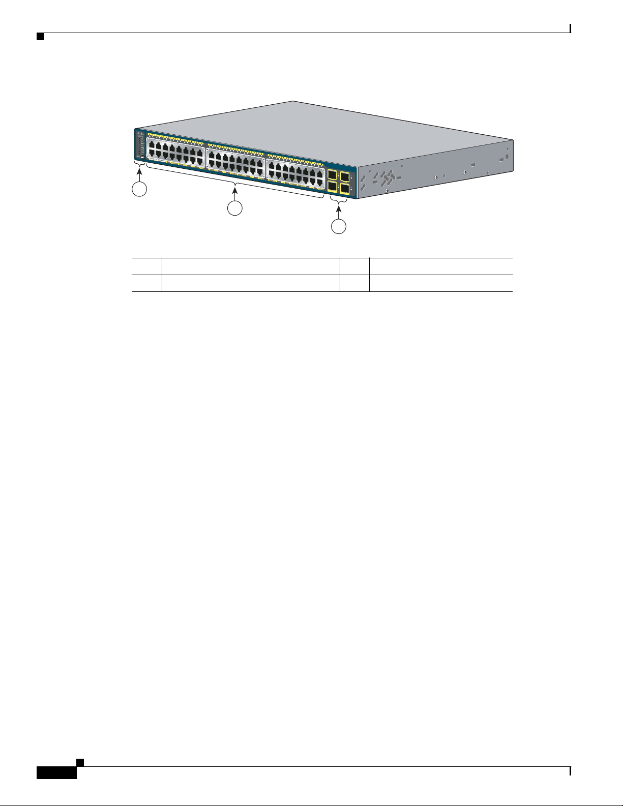
The swit ch fr ont pa nel in Figure 1-1 has the 10/100/1000 PoE p orts, t he SFP module slots, an d the LEDs.
OL-17784-01
Catalyst 2975 Switch Hardware Installation Guide
1-1
Page 10
Front Panel
205075
C
a
t
a
l
y
st
2
9
7
5
G
S
eri
e
s
Po
E
-4
8
3
2
1
Chapter 1 Product Overview
Figure 1-1 Catalyst 2975 Switch Front Panel
1 Mode button and switch LEDs 3 SFP module slots
2 10/100/1000 PoE ports
1. Port numbering is from left to rig h t, with port 1 on the far left. Th e f irst member of the pair (port 1) is above
the sec ond m e mbe r (p ort 2) . Mod ul e s lot n um ber s ar e 4 9, 51 upp er , 50, 5 2, low e r.
1
10/100/1000 PoE Ports
The 10/100/1000 PoE ports use RJ-45 connectors with Ethernet pinouts. The maximum cable length is
328 feet (100 meters ). The 100BASE-TX and 1000BAS E-T traffic requ ires Category
Categor y
6 unshielded twisted pair (UTP) cable. The 10BASE-T traff ic can use Ca tegory 3 or Ca tegory
4 UTP cabl e.
The ports provide PoE support for devices compliant with IEEE 802.3af and also provide Cisco
prestandard PoE support for Cisco IP Phones and Cisco Aironet Access Points.
The switch delivers 15.4 W o f PoE on any 24 of the 48 ports , or any comb ination of the ports del iver an
aver ag e of 7. 7 W of PoE at the sam e ti me, up to a maxim um swi t ch power ou tput of 37 0 W. On a pe r -p ort
basis, you can control whether or not a port automatically provides power when an IP phone or an access
point is connect ed .
For more in for m a tio n ab o ut p or t co nn ect io n s an d port sp ec ific at io ns, see th e “10/100/1000 PoE Port
Connections” section on page 2-19, and Appendix B, “Connector and Cable Specifications.”
SFP Modul e Sl ots
The switch has four Gigabit Ethernet SFP module slots. Y ou can use any combination of these Cisco SFP
modules:
–
100BASE-FX multimode fiber (MMF)
–
1000BASE-BX
5, Category 5e, or
–
1000BASE-LX
–
1000BASE-SX
–
1000BASE-ZX
–
1000BASE-T
–
Coarse wavelength- divi s io n m u lt ip lexing (C W D M )
1-2
Catalyst 2975 Switch Hardware Installation Guide
OL-17784-01
Page 11
Chapter 1 Product O v er view
93 4 521 8
7
6
LEDs
Front Panel
For more information about SFP modules, see yo ur SFP module documentation and the “Installing SFP
Modules” section on page 2-17. For ca bl e s p eci ficati on s, see Appendix B, “Connect or a nd C ab le
Specificat io n s .” For an updated list of supported SFP modules, see the switch release notes on
Cisco.co m.
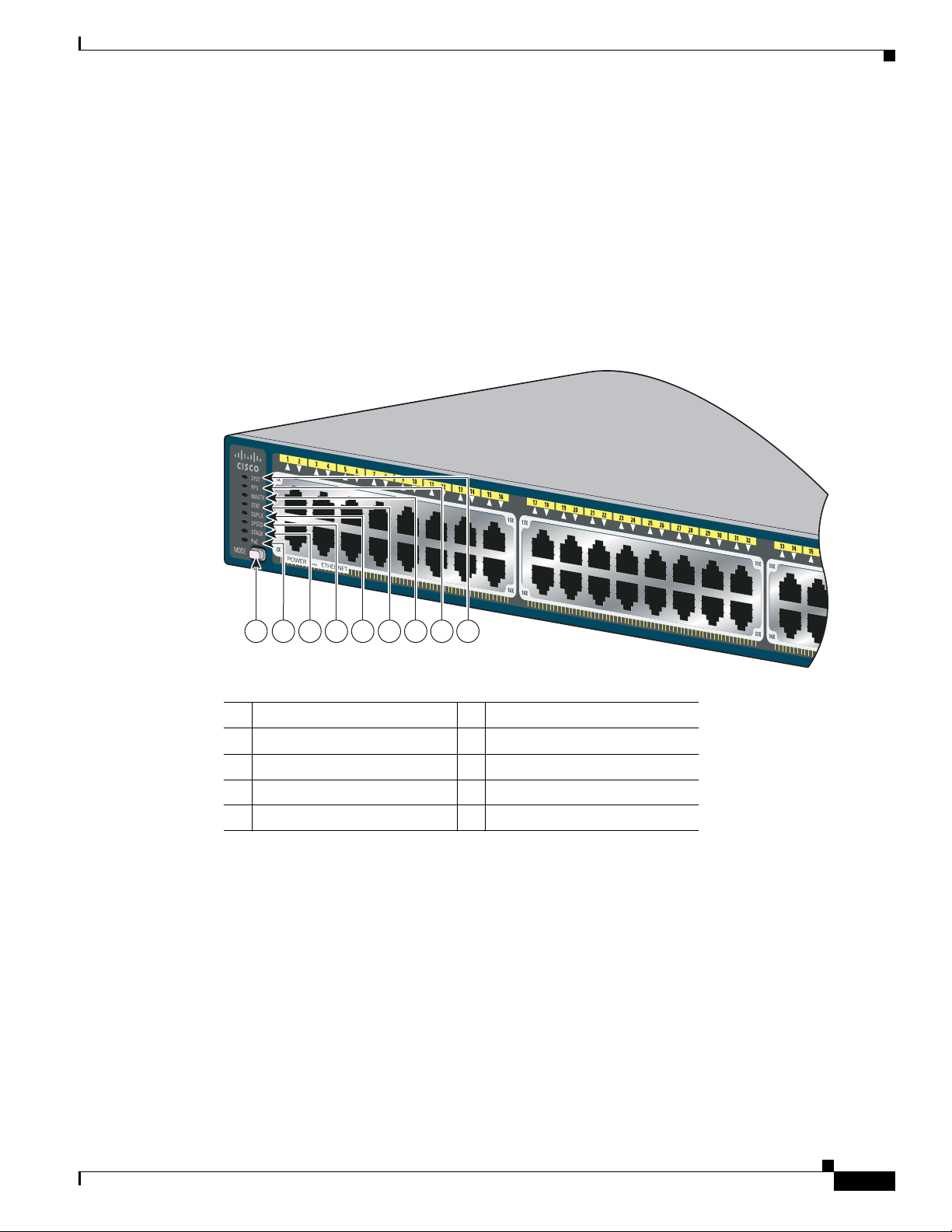
Y ou can use the switch LEDs to monitor switch activity and its performance. Figure 1-2 shows the switch
LEDs and t he M ode button th at you u se t o select one o f th e po r t modes.
Figure 1-2 Switch LEDs and Mode Button
OL-17784-01
1 Mode button 6 Status LED
2 PoE LED 7 Master LED
3 Stack LE D 8 RPS1 LED
4 Speed L ED 9 System LED
5 Duplex LED
1. RPS = red undant pow er sy stem.
Catalyst 2975 Switch Hardware Installation Guide
1-3
Page 12

Front Panel
System LED
RPS LED
Chapter 1 Product Overview
Table 1-2 Syst em LED
Color System Status
Off System is not powered on.
Green System is operatin g norm ally.
Amber System is rec ei vi ng po wer but is no t f unct io nin g prop er ly.
For inform at io n on t he Sy s tem LED colors du r ing pow er-on se lf -t est (PO S T), see th e “Switch POST
Results” section on page 3-1.
Table 1-3 RPS LED
Color RPS Status
Off RPS is off o r no t properly c o nn e c te d .
Green RPS is connected and ready to provide back-up power.
Blinking green RPS is connected but is unavailable because it is providing power to another device
(redundancy has been allocated to a neighboring device).
Amber The RPS is in sta ndby mod e or in a faul t c on diti on. See t he RPS docu ment at ion for
more information about the standby mode and fault conditions.
Blinking amber The pow er sup pl y in a sw itch h as fa i le d , and t he RPS is pr ov iding power t o t he
switch (redundancy has been allocated to this device).
For more information about the Cisco RPS 2300 or the Cisco RPS 675, see the “Related Publi cat io ns”
section.
Master LED
Table 1-4 Master LED
Port Mode D esc ription
Off Switch is n ot th e s tac k m ast er.
Green Switch is the stac k m aster or a sta nd al o ne s w itc h.
Amber An error occurred when the stack was electing the stack master switch, or another type
Port LEDs and Modes
Each port and mod ule sl ot h as a por t L ED. As a gro up or indi v id uall y, the LED s sho w i nfo rmat ion a bou t
the switch and about the individual ports.
and meanings .
Catalyst 2975 Switch Hardware Installation Guide
1-4
of stack error occurred.
Table 1- 5 lists the mode LEDs and their associated port modes
OL-17784-01
Page 13
Chapter 1 Product O v er view
Table 1-5 Port Mode LEDs
Mode LED Port Mode Description
STAT Port status The port status. This is the default mode.
DUPLX Port duplex The port duplex mode: full duplex or half duplex.
SPEED Port sp eed The port operating speed: 10, 100, or 1000 Mb/s.
STACK Stack member status
Front Panel
Note The ports operate only in full-duplex mode.
The stack member status.
Stack port status
The stack port status. See the “Stack LED” section on page 1-6
for more information.
PoE PoE p or t power The PoE status.
Table 1-6 PoE Mode LED
Color PoE Status
Off PoE mode is not select ed. No port has bee n denied power or is in a fault condition.
Green PoE mode is selected, and the port LEDs show the PoE status.
Blinking amber PoE mode is not selected. At least one port was denied power, or at least one port
has a P o E fa u l t .
To select or change a mode, press the Mode button until the desired mode is highlighted. When you
change p ort m o des , th e meani ngs o f th e p o rt LED colo rs al so c ha ng e.
Table 1-7 Me a n in g s of L ED C o lo r s in Di fferent M o des
Port Mode Port LED Color Meaning
PoE Off PoE is off. If the powered device is receiving power from an AC
power sour ce, the port LED is off even if th e p owe red devi ce is
conne cted to the switc h po rt.
Green PoE is on. The port LED is green only when the switch port is
providing power.
Alternating
green and
PoE is denied because providing power to the powered device will
exceed the 3 70 - W s w it ch p ower c ap acity.
amber
Blinki ng am ber PoE is off due to a fault.
OL-17784-01
Caution Noncompliant cabling or powered devices can cause a
PoE port fault. Use only standard-compliant cabling to
connect Cis co pr est anda rd IP P hon es and wi rele ss acce ss
points or IEEE
802.3af-compliant devices. You must
remove any c a bl e o r d evice th at ca uses a PoE fau lt.
Amber PoE f o r the p o rt is disabled. (P oE is en a b led by de fa u lt.)
Catalyst 2975 Switch Hardware Installation Guide
1-5
Page 14

Front Panel
Table 1-7 Meanings of LED Colors in Different Modes (continued)
Port Mode Port LED Color Meaning
STAT
(port status)
DUPLX
(duplex)
SPEED Off Po rt is operat in g at 10 M b /s.
STACK
(stack member)
Off No li nk , or por t was a d m i nistrative l y s hu t down.
Green Link presen t.
Blinking green Activity. Port is sending or receiving data.
Alternating
green-amber
Link fault. Error frames can affect connectivity, and errors such as
excessive collis i on s, cycl ic redunda ncy ch ec k ( C RC ) er r ors , an d
alignment and jabber errors are monitored for a link-fault
indication.
Amber Port i s bl ocked by S p a n ning Tree Prot ocol ( S TP ) a n d is no t
forwarding data.
After a port is reconfigured, the port LED ca n remain amber for up
to 30 seconds as STP checks the switch for possible loops.
Blinki ng am ber Port is blocked by S TP an d is sendin g a n d r e ceiving p ackets.
Off Port is operating in half duplex.
Green Port i s op er at ing in f u ll du plex.
Green Port is oper at in g at 10 0 M b /s .
Blinking green Port is op er at in g at 10 0 0 M b/s .
SFP module ports
Off Port is oper at in g at 10 M b /s .
Green Port is oper at in g at 10 0 M b /s .
Blinking green Port is op er at in g at 10 0 0 M b/s .
Off No stack member has that member number.
Blinking green Stack me m b er nu mb er.
Green Membe r numbers of other stack memb er swi tches.
Chapter 1 Product Overview
Stac k L ED
1-6
If your sw it ch es are s t ack ed an d y o u p res s th e M o d e butto n on any sw it ch in th e s t ack , al l t he s w itc he s
change to display the same selected mode. For example, if you press the mode button on the stack master
to display SPEED, all the o ther stack m emb ers display SPEED.
Even if PoE m o de is not selected, th is LED s t il l sh ows P oE p ro b lem s if t hey are d etected.
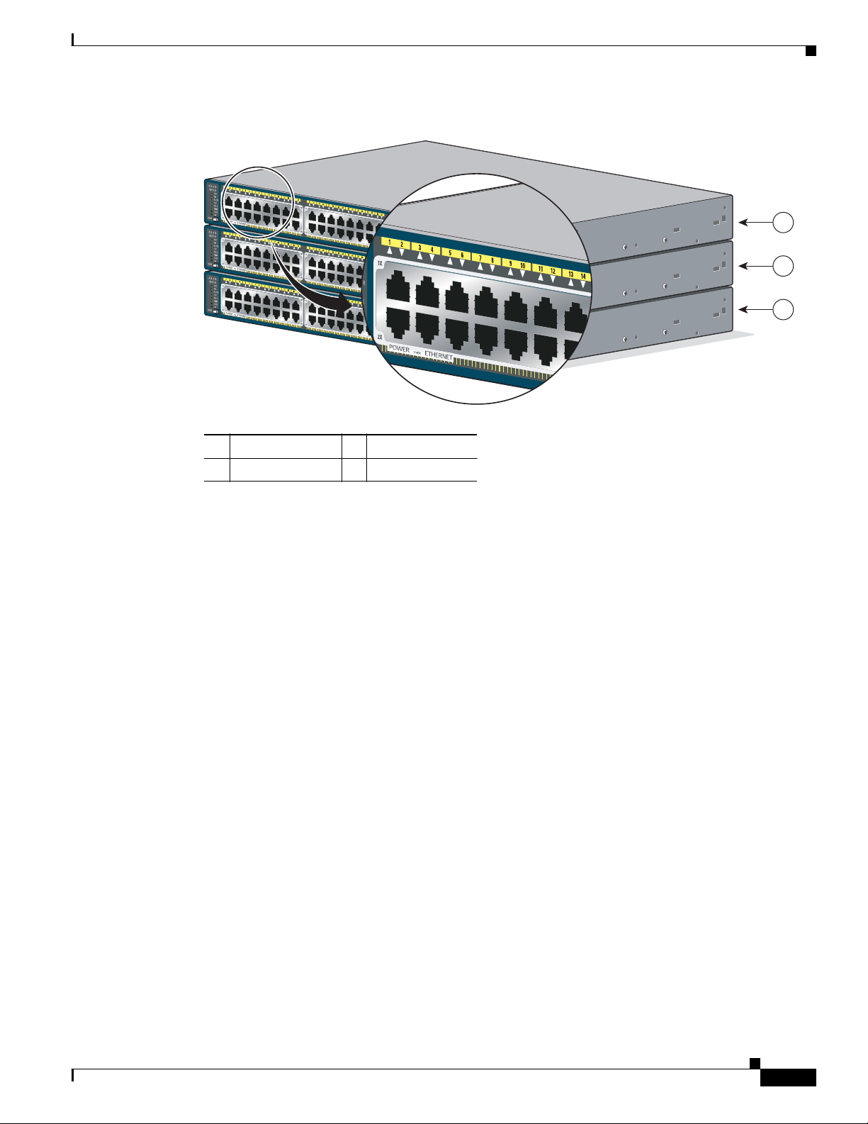
The stack LED shows the sequence of member switches in a stack. Up to nine switches can be members
of a stack . Th e firs t n ine port L ED s sh ow t he m e m b er nu mb er o f a switch in a s t ack .
the LED s o n th e fi rst sw it ch , w h ich is st ack member nu mb er 1 . F or ex am p le , i f yo u pres s th e M o de
button an d s elect S t a ck , th e LED for port 1 blinks gr e en. Th e L EDs f or p or t 2 an d 3 are so lid green , as
these represent the member numbers of other stack members. The other port LEDs are off because there
are no more members in the sta ck.
Catalyst 2975 Switch Hardware Installation Guide
Figure 1-3 show s
OL-17784-01
Page 15
Chapter 1 Product O v er view
Figure 1-3 Stack LED
Front Panel
C
a
t
a
l
y
st
2
9
7
5
G
S
eri
e
s
Po
E
-4
8
C
a
t
a
l
y
st
2
9
7
5
G
S
eri
e
s
Po
E
-4
8
C
a
t
a
l
y
st
29
7
5
G
S
eri
e
s
Po
E
-4
8
1
2
3
272679
1 Stack me m b er 1 3 Stack member 3
2 Stack me m b er 2
When you se l ect th e S tac k LED , th e r ep r esen ta tive Stack LEDs ar e g r een w h en th e s tac k por ts ( o n th e
switch rear panel) are up, and the representative Stack LEDs are amber when the ports are down. SFP
module port LEDs 51 and 52 on the switch show the status for stack ports 1 and 2, respectively.
If the port LEDs are green on all the switches in the stack, the stack is operating at full bandwidth. If any
port LED is not green, the stack is not operating at full bandwidth.
OL-17784-01
Catalyst 2975 Switch Hardware Installation Guide
1-7
Page 16
Rear Panel
CO
NSOLE
D
C
I
N
P
U
T
S
F
O
R
R
E
M
O
T
E
P
O
W
E
R
S
U
P
P
L
Y
S
P
E
C
I
F
I
E
D
I
N
M
A
N
U
A
L
119772
2
3
4
5
S
T
A
C
K
1
S
T
A
C
K
2
1
Rear Panel
Chapter 1 Product Overview
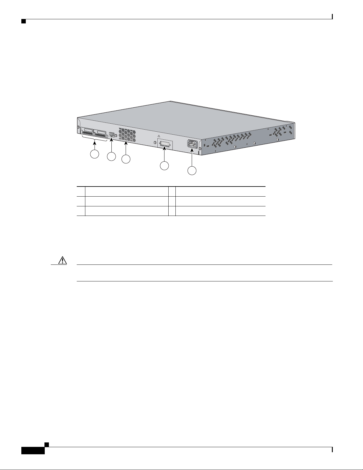
The switch re a r pa ne l i n Figure 1-4 has two stack ports, an RJ-45 console port, an RPS connector, and
an AC power conn ect o r.
Figure 1-4 Catalyst 2975 Switch Rear Panel
Stack Ports
Caution Use only approved cables, and connect only to other Catalyst 2975 switches. Equipment might be
Console Po rt
1 Stack ports 4 R PS c onnector
2 RJ- 45 c onso le port 5 AC power connector
3 Fa n exhaust
The Cataly s t 29 7 5 swi tc h shi ps with a 0. 5-m e ter stack cab le to co nn ec t the stack p or ts .
damaged if connected to other nonapproved Cisco cables or equipment.
You can orde r t h ese s t ac k c ab les from y o ur C isco sale s r ep re sen tat ive:
• STACK-CAB-50CM-NH= (0.5-meter cable)
• STACK-CAB-1M-NH= (1-meter cable)
• STACK-CAB-3M-NH= (3-meter cable)
You can connect the switch to a PC by means of the console port and the supplied RJ-45-to-DB-9 female
cable. If y ou wa n t t o co nnect the s witch conso l e p or t to a ter minal, yo u ne ed to p r ovide an
RJ-45-to-DB-25 female DTE ada pter. You can order a kit (part number ACS-DSBUASYN=) containing
that adapter from Cisco. For console port and adapter pinout information, see the
“Connect or an d Cable
Specifications” section on page B-1.
Catalyst 2975 Switch Hardware Installation Guide
1-8
OL-17784-01
Page 17

Chapter 1 Product O v er view
RPS Conne ct or
Management Options
The Cisco RPS 2300 (model PWR-RPS2300) and the Cisco RPS 675 (model PWR675-AC-RPS-N1=)
support th e Catalys t
2975 switch.
Warning
Attach only the following Cisco RPS model to the RPS receptacle:
PWR-RPS2300 , PWR675- AC-RPS -N1=.
Connec t the Cat alyst 2975 switch and the redundant power system to the same AC power source.
Cisco RPS 2300 and RPS 675
The Cisco RPS 2300 has two output levels: –52 V and 12 V with a total maximum output power of
2300
W. The Cisco RPS 675 has two out put levels : –48 V and 12 V with a total maximum output power
of 675
W.
The RPS 2300 and RPS 675 are redundant power systems that can support six external network devices
and provide power to one failed device at a time. The RPS automatically senses when the internal power
supply of a connected device fails and provides power to the failed device, preventing loss of network
traffic. For more information, see the
AC Power Con nect o r
The switch i s p owered through th e in ter n al power su p pl y. The inter n al power supp l y i s an a ut ora n g ing
unit that supports input voltages between 100 and 240 VAC. Use the supplied AC power cord to connect
to an AC power outlet.
Statement 370
“Relate d Publicat ions” section.
Management Options
• Cisco Network Assistant
Cisco Network Assistant is a PC-based network management GUI application for LANs of small
and mediu m -s iz ed busi ne s ses. You can use the G UI to co n fig ure and man ag e s w i tch cl u ster s o r
standalone switches. Cisco Network Assistant is available at no cost and can be downloaded from
this URL :
http:/ /w w w.cisco .com/g o/ network a ss is t ant
For infor mation on s t ar ti ng t he Netwo rk A ss i stan t application, s e e t he Getting Started with Cisco
Network Assistant guide on Cisco.com.
OL-17784-01
Catalyst 2975 Switch Hardware Installation Guide
1-9
Page 18

Management Options
Chapter 1 Product Overview
• Device manager
You can use the device manager, which is in the switch memory, to manage individual and
standalone switches. This web interface offers quick configuration and monitoring from anywhere
in your network through a web browser. For more information, see the switch getting started guide
and th e device m anage r onli ne help.
• Cisco I O S CL I
You can fully con fig ure an d monitor the switch and swi tch clu ster membe rs f rom th e CLI . You can
access t he CLI by conn ecting y ou r m anage m ent station di rectly to the sw itch cons o le port or by
using Telnet fr om a r e mote m anage m e n t s ta t ion. Se e the sw itch comm and re ferenc e o n Cisco .com
for more information.
• CiscoWorks application
The Cisc oWork s L AN Mana ge ment Sol ut io n ( LMS) i s a su it e of ma na gement t ools th at si mpli fy the
configuration, administration, monitoring, and troubleshooting of Cisco networks. See the LMS
documentation for more information.
• SNMP network management
You can manage swit ches fr om a Si m p le Networ k Man ag e m e nt Prot ocol ( SNMP)- compat i b le
management stat ion that is runni ng platfo rms suc h as HP OpenV ie w or Sun Net Mana ger . The switch
supports a compreh ensive set of Mana gement Information Base (MIB) extensions and four Re mote
Monitoring (RMON) groups. See the switch software configuration guide on Cisco.com and the
documentation that came with your SNMP application for more information.
Network Configurations
See the sw i tch s o f twar e co n fig uration gu id e on Cisco.com for network configuration concepts and
examples o f u sin g th e s w i tch t o cr eat e d ed ic a te d net wo rk segment s an d in terconn ect in g th e segments
through Gigabit Ethernet connections.
1-10
Catalyst 2975 Switch Hardware Installation Guide
OL-17784-01
Page 19

CHAPTER
2
Switch Installation
Read th ese topics an d perform the proc ed ures in th is or d er :
• Prepa rin g, pa ge 2-1
• Planning a Switch Stack, page 2-6
• Installin g th e S w i tch , p ag e 2-9
• Conne cting to the Stack P o r ts , page 2-16
• Installing SFP Modules, page 2-17
• 10/10 0/ 1000 Po E P ort C on nections, page 2-19
• Where to Go Next, page 2-20
For init ial sw itch set up , how to assign th e s w i tch I P a dd r ess , a nd f o r pow er in g inform at io n, see th e
switch gettin g starte d gu ide on Cisco .com .
Preparing
• Safety Warnings, page 2-1
• Install ati o n G u id el ines, pa ge 2-5
• Box Contents, page 2-5
• Tools and Equi pme nt, pa ge 2-5
Safety Warnings
This se ctio n i nclu de s th e b asi c in sta lla ti on caut io n and wa rning sta t ement s . Re ad th is s ect i on bef ore yo u
start the installation p roc e du r e. Trans la tio n s o f th e w arni n g s t at emen ts appear in t he Regulatory
Compliance and Safety Information for the Catalyst
online at Cisco.com.
Warning
To prevent the switch from overheating, do not operate it in an area that exceeds the maximum
recommended ambient temperature of 113•F (45•C). To prevent airflow restriction, allow at least
3 inches (7.6 cm) of cl earance around the v entilati on openings.
2975 Switch guide on th e documentation C D an d
Statement 17B
OL-17784-01
Catalyst 2975 Switch Hardware Installation Guide
2-1
Page 20

Preparing
Chap te r 2 Switch Ins tallati o n
Warning
Warning
Warning
Warning
Warning
Warning
Before working on equipment that is connected to power lines, remove jewelry (incl uding rings,
necklaces, and watches). Metal objects will heat up when connected to power and ground and can
cause serious burns or weld the metal object to the terminals.
Statement 43
Do not stack the chassis on any other equipment. If the chassis falls, it can cause severe bodily injury
and equipment damage.
Statement 48
If a redundant power system (RPS) is not connected to the switch, ins tal l an RPS connect or cover on
the back of the switch.
To comply with safety regulations, mount switches on a wall with t he front panel f acing up.
Statement 265
Statement 266
Attach only the following Cisco RPS model to the RPS receptacle:
PWR-RPS2300 , PWR675- AC-RPS -N1=.
Statement 370
Read the wall-mounting instructions carefully before beginning installation. Failure to use the
correct hardware or to follow the correct procedures could result in a hazardous situation to people
and damage to the system.
Statement 378
Warning
Warning
Warning
Do not work on the system or connect or disconnect cables during periods of lightning activity.
Statement 1001
Read the installation instructions before connecting the system to the power source.
Statement 1004
To prevent bodily injury when mounting or servicing this uni t i n a rack, y ou must t ake special
precautions to ensure that the system remains stable. The following guidelines are provided to
ensure your safety:
• T his unit should be mounted at the bottom of the rack if it is the only unit in the rack.
• When m ounting this unit in a partially filled rack, load the rack from the bottom to the top with the heaviest
component at the bottom of the rack.
• If the rack is provided with stabilizing devices, install the stabilizers before mounting or servicing the unit in
the rack.
Statem ent 10 06
2-2
Catalyst 2975 Switch Hardware Installation Guide
OL-17784-01
Page 21

Chapter 2 Switch Installation
Preparing
Warning
Warning
Warning
Warning
Warning
Warning
Class 1 laser product.
Statement 1008
This unit is intended for installation in restrict ed access areas. A r estricted access area can be
accessed only through the use of a special tool, lock and key, or other means of security.
Statement 1017
The plug-socket combination must be accessible at all times, because it serves as t he main
disconnecting device.
Statement 1019
This equipment must be grounded. Never defeat the ground conductor or operate the equipment in the
absence of a suitably installed ground conductor. Contact the appropriate electrical inspection
authority or an electrician if you are uncertain that suitable grounding is avai lable.
Statement 1024
This unit might have more than one power supply connection. All connections must be removed t o
de-energize the unit.
Statement 1028
Only trained and qualified personnel should be allowed to install, replace, or service this equipment.
Statement 1030
Warning
Warning
Warning
Warning
Ultimate disposal of this product should be handled according to all national laws and regulations.
Statement 1040
For connections outside the building where the equipment is installed, t he following ports must be
connected through an approved network termination unit with integral circuit protection: 10/100/1000
Ethernet.
Statement 1044
When installing or replacing the unit, the ground connection must always be made first and
disconnected last.
Statem ent 10 46
This warning symbol means danger. You are in a situation that could cause bodily injury. Before you
work on any equipment, be aware of the hazards involved with electrical circui try and be familiar
with standard practices for preventing accidents. Use the statement number provided at the end of
each warning to locate its translation in the translated safety warnings t hat accompanied this de vice.
Statement 1071
OL-17784-01
Catalyst 2975 Switch Hardware Installation Guide
2-3
Page 22

Preparing
Chap te r 2 Switch Ins tallati o n
Warning
Voltages that present a shock hazard may exist on Power over Ethernet (PoE) circuits if
interconnections are made using uninsulated exposed metal contacts, conductors, or terminals.
Avoid using such interconnection methods, unless the exposed metal parts are located within a
restricted access location and users and service people who are authorized within the restricted
access location are made aw are of the hazard. A restricted access area can be a ccessed only th rough
the use of a special tool, lock and key or other means of security.
Warning
Warning
Caution To comply with the Telcordia GR-1089 Network Equipment Building Systems (NEBS) standard for
No user-serviceable parts inside. Do not open.
Statement 1073
Installation of the equipment must comply with local and national el ectrical codes.
Statement 1072
Statement 1074
electromag n et ic compati bi lit y an d safety, connec t t he Et he rn et ca bl es o n ly to i nt ra bui ld in g or
nonexposed wiring or cabling.
Caution To comply with the Telcordia GR-1089 NEBS standard, PoE or non-PoE 10/100/1000 Ethernet port
cables that exit from either the left side or right side of the switch should be routed and tied to the nearest
rack metal hardware.
Note The grounding architecture of this product is DC-isolated (DC-I)
2-4
Catalyst 2975 Switch Hardware Installation Guide
OL-17784-01
Page 23

Chapter 2 Switch Installation
Installation Guidelines
Before i nstalling th e switc h, ver if y th at th es e g ui de lines are met:
• Front-panel indicators can be easily read, and access to ports is sufficient for unrestricted cabling.
• AC power cord reaches from the power outlet to the rear panel connector.
• Access to th e s witch rear pane l to co nn ec t th e R P S 230 0 o r th e RP S 6 7 5. If not, cab le th e s w it ch es
before rack-mounting.
• Cabling is away from sources of electrical noise, such as radios, power lines, and fluorescent
lighti ng fixture s . Make s u re that th e c a b li ng is awa y f r om other devi ces that m ig h t dama g e the
cables.
• For copper connectio ns on Eth ernet ports, cable len gt hs f rom t he sw it ch to c on n ect ed d evices can
be up to 328 feet (100
• For cable requirements for SFP module connections, see the “Cables and Adapters” section on
page B-3.
• Operating environment is within the ranges listed in Appendix A , “Technical Speci fication s.”
• Airflow ar ound the sw i tch an d th r ou g h th e ve nt s is unrestr i cte d.
Preparing
meters).
• Temperat ure around the unit does not exceed 113°F (45°C). If the switch i s in a closed or multirack
assembly, the temperature around it might be greater than normal room temperature.
• Cooling mechanisms, such as fans and blowers in the switch, can draw dust and other particles
causing co n taminant bu ildup in s id e th e chassis , wh i c h can r esult in system malfunction. You must
install this equi pm ent in an environment as free from dust and foreign conductive mater ial (such as
metal flake s from co nst ruct ion act ivities) as is possib le.
These stan d ar ds pr ovid e g u id elines for a cce pt ab le working e nviron men ts a nd a cceptable levels o f
suspended particulate matter:
–
Network Equipment Building Systems (NEBS) GR-63-CORE
–
National El ect r ica l M an u fac tu re rs A ss oc iat io n ( NE M A) Type 1
–
International Electrotechnical Commission (IEC) IP-20
Box Conten t s
The switch getting started guide describes the box contents. If any item is missing or damaged, contact
your Cisco representative or reseller for support.
Tools and Equipment
You need to s u p pl y a numbe r-2 P h ill ips screwd r iver to rack- mount the s w it ch .
OL-17784-01
Catalyst 2975 Switch Hardware Installation Guide
2-5
Page 24

Plann ing a Swit ch St a ck
250579
Planning a Switch Stack
If you pl an to s t ack y o ur s w it ch es, read th ese s ec tio n s :
• Stack Guide lines , page 2-6
• Stack Cabling, page 2-6
• Stack Bandwidth and Partitioning Examples, page 2-8
• Power-On Sequence for Switch Stacks, page 2-9
Stack Guide li nes
For general concepts and procedures see the switch software configuration guide on Cisco.com.
Before c on n ect in g th e s w i tch es in a stac k, kee p in m in d th ese guideli ne s:
• Connect only Catalyst 2975 switches in a switch stack. The Catalyst 2975 switch does not support
mixed sta ck co nfi gur ation s. You cannot sta ck Ca tal yst
or Catalyst 3750-E switches.
Chap te r 2 Switch Ins tallati o n
2975 switches with Catalyst 3750 switches
Stack Cabli ng
• Depending on your installation, you might need different cables sizes. If you do not specify the
length o f th e st ack cable, th e 0.5-met er cable is s u pplied. If y ou n eed t he 1 -meter or t he 3- meter
cable, yo u can o rd er it from y ou r Ci sco s u pplier. For cable par t num b er s, see the
section on page 1-8.
• Access to t he s witch rear p an e l an d to th e re ar o f th e rack. If y o u do n ot h ave acc es s, cab le the
switches before rack-mounting.
In Fi gure 2-1 the swi tch es ar e s t acke d in a ver tic al ra ck o r on a tab l e. The conn ec ti on s are redun da nt .
Figure 2-1 Stacking Switches with the 0.5-meter Stack Cable
“Stack Po r ts”
2-6
Catalyst 2975 Switch Hardware Installation Guide
OL-17784-01
Page 25

Chapter 2 Switch Installation
In Fi gure 2-2 the swi tch es ar e s t acke d in a ver tic al ra ck o r on a tab l e. The conn ec ti on s are redun da nt .
Figure 2-2 Stacking Switches with 0.5-meter and 3-meter Stack Cables
Figure 2-3 and Figure 2-4 show switch stacks that use the 3-meter s t ack ca bl e i n ad di ti on t o t he
0.5-meter c ab le. Th e c on n ect io ns ar e r ed u ndan t.
Planning a Switch St ack
250580
Figure 2-3 Stacking up to Eight Switches Side-by-Side
Figure 2-4 Stacking Nine Switches Side-by-Side
86825
OL-17784-01
Catalyst 2975 Switch Hardware Installation Guide
2-7
Page 26

Plann ing a Swit ch St a ck
272680
A
B
C
272681
A
B
272682
A
B
C
272683
A
B
Stack Bandwid t h and Partitioning Examp les
Figure 2-5 shows a stack that provides full bandwidth with redundant connections.
Figure 2-5 Stack with Full Bandwidth Connections
Figure 2-6 shows a stack wit h inco mplete stack c ab ling conne ctions. Th is stack p rovides only half
bandwidth and does not have redundant connections.
Figure 2-6 Stack with Half Bandwidth Connections
Chap te r 2 Switch Ins tallati o n
In Fi gure 2-7, the stack cable is bad in link B; therefore, this stack provides only half bandwidth and
does not ha ve redu nda nt co nne ctio ns . In Figure 2-8, link B is bad; theref ore, this stac k part itio ns into
two stacks, an d switc h 1 an d switc h 3 are stack ma sters.
Figure 2-7 Example of a Stack with a Failover Condit ion
Figure 2-8 Example of a Partitioned Stack with a Failover Conditi on
2-8
Catalyst 2975 Switch Hardware Installation Guide
OL-17784-01
Page 27

Chapter 2 Switch Installation
Power-On Sequence for Swit ch Stacks
Consider th es e g ui de li ne s be for e y o u power o n th e s w i tch es in a stack:
• The sequen ce in wh ich t he sw it ch es a re first powered o n mig ht affect the swit ch th at be co m es the
stack master.
• If you want a particular switch to be the stack master, power on that switch first. This switch
becomes t he stack master an d rem ain s th e st ack m aster until a m a s te r re- el ection is req u ired . A f ter
1
minute, power on the other switches in the stack.
• If you have no preference as to which switch becomes the stack master, power on all the switches
in the s tac k w ith in a 1 -minute t ime fr am e. These sw i tch es partici pa te in t he s tac k m ast er el ect io n .
Switches powered on after the 1-minute timeframe do not participate in the election.
• Power off a switch before you add it to or remove it from an existing switch stack.
For condit io n s th at can cau s e a s ta ck m ast er r e- el ect io n or t o m an ua ll y e le ct the stack m a s ter, see th e
“Managin g S w it ch Stacks” chap ter in th e s w itc h s oftw ar e co nfiguration g ui d e o n Cisco.com .
Installing the Switch
Installing the Switch
This secti o n d esc ri b es these inst all a t ion p r o ced ures:
• Rack-Mounting, page 2-9
• Wall-Mounting, page 2-13
• Table- or Shelf-Mounting, page 2-16
• After Switch Installation, page 2-16
Rack-Mounting
Installation in other than 19-inch racks requires an optional bracket kit not included with the switch.
Figure 2-9 sh ows th e s t an da rd 1 9- i nc h b rack ets an d th es e op ti onal m o u nt in g brac ket s :
• 23/24-inch bracket, part number 700-12398-XX
• ETSI bracket, part number 700-19781XX
Warning
To prevent bodily injury when mounting or servicing this unit in a rack, you must take special
precautions to ensure that the system remains stable. The following guidelines are provided to
ensure your safety:
• This unit should be mounted at the bottom of the rack if it is the only unit in the rack.
• Wh en mounting this unit in a partially filled rack, load the rack from the bottom to the top with the heaviest
• If the rack is provided with stabilizing devices, install the stabilizers before mounting or servicing the unit in
component at the bottom of the rack.
the rack.
Statement 1006
OL-17784-01
Catalyst 2975 Switch Hardware Installation Guide
2-9
Page 28

Installing the Switch
132869
19 inch
23/24 inch
ETSI
Catalyst 2975G
Series
PoE-48
205084
Chap te r 2 Switch Ins tallati o n
Figure 2-9 Rack-Mounting Brac kets
Attaching the Rack-Mount Brackets
First re m ove t h e s cr ews fr o m the sw it ch ch as sis so th at th e mountin g b rackets c an be attached
(
Figure 2-10). For bracket attachment, remove one or two screws, depending on the bracket mounting
position.
Figure 2-10 Removing Screws from the Switch
2-10
Catalyst 2975 Switch Hardware Installation Guide
OL-17784-01
Page 29

Chapter 2 Switch Installation
Use three P h ill ip s f la t- he ad s cr ews t o att ach the lo n g s ide o f th e bracket to ea ch side of t he s w it ch
(
Figure 2-11).
Figure 2-11 Attaching Brack ets f or 19-inch Rac ks
2
Installing the Switch
1
C
a
t
a
ly
s
t 2
9
7
5
G
S
e
r
ie
s
P
o
E
-4
8
2
3
C
a
t
a
ly
s
t 2
9
7
5
G
S
eries
P
o
E
-4
2
8
4
S
T
A
C
K
1
2
C
O
N
S
O
LE
S
T
A
C
K
2
D
C
IN
P
U
T
S
F
O
R
R
P
EMO
O
W
T
E
E
R
S
UPP
S
P
E
L
C
Y
I
F
IE
D
IN
M
A
N
U
A
L
1 Front-mounting position 3 Mid-m o unting p ositio n
2 Num b e r-8 P hillips flat-h e a d s crews 4 Rear-mounting position
2
205081
2
OL-17784-01
Catalyst 2975 Switch Hardware Installation Guide
2-11
Page 30

Installing the Switch
205082
Catalyst 2975G
S
er
ie
s
PoE-48
Catal
yst
29
75G
S
e
r
ies
PoE
-48
C
O
N
S
O
L
E
D
C
I
N
P
U
T
S
F
O
R
R
E
M
O
T
E
P
O
W
E
R
S
U
P
P
L
Y
S
P
E
C
I
F
I
E
D
IN
M
A
N
U
A
L
STACK 1
STA
CK 2
21
3
6
4
5
4
Mounti ng in a Rack
After the br ac ket s are attached , u se the fo ur s u p plied P h il li ps machine s cr ews t o att ach t he b ra cket s t o
the rack (
bracket.
When you complete the switch installation, see the “After Switch Installation” section on page 2-16 fo r
more information on switch configuration.
Figure 2-12 Mounting the Switch in a Rack
Chap te r 2 Switch Ins tallati o n
Figure 2-12). Use the black Phillips machine screw to attach the cable guide to the left or right
1 Phillip s machine screw, black 4 Number-1 2 Phillips m a chine sc rews
2 Cable guide 5 Mid-m o unting p ositio n
3 Front-mounting position 6 Rear-mounting position
2-12
Catalyst 2975 Switch Hardware Installation Guide
OL-17784-01
Page 31

Chapter 2 Switch Installation
C
a
t
a
ly
st 29
75
G
S
er
i
es
P
oE
-48
Wall-Mounting
• Attaching the Brackets for Wall-Mounting, page 2-13
• Attaching the RPS Connector Cover, page 2-14
• Mounting on a Wall, page 2-1 5
Installing the Switch
Warning
Read the wall-mounting instructions carefully before beginning installation. Failure to use the
correct hardware or to follow the correct procedures could result in a hazardous situation to people
and damage to the system.
Statement 378
Attaching the Brackets for Wall-Mounting
Figure 2-13 s hows h ow to attach a 1 9- i nc h b r ack et to o ne s id e of t he s witch. Follow th e same step s t o
attach the second bracket to the opposite side.
Figure 2-13 Attachi ng the 19-inch Brackets for Wall-Mounting
1
272684
OL-17784-01
1 Phillips truss-head screws
Catalyst 2975 Switch Hardware Installation Guide
2-13
Page 32

Installing the Switch
CON
S
O
L
E
D
C
I
NPUT
S
F
O
R
R
E
M
O
T
E
PO
W
E
R
SU
PP
LY
S
PE
C
I
F
I
ED
I
N
M
AN
U
A
L
STACK 1S
TACK
2
272685
21
3
Attaching the RPS Connector Cover
If you ar e n o t u sing an R P S w it h yo ur sw itch, us e the two P h il li ps pan-head s cr ews to attach the RP S
connecto r cover t o th e back of t he sw itch (
Chap te r 2 Switch Ins tallati o n
Figure 2-14).
Warning
If an RPS is not connected to the switch, i nstall an RP S connector cover on t he back of the switch.
Statement 265
Figure 2-14 Attachi ng the RPS Connector Cover
1 Phillip s p an - head scr ews 3 RPS connector
2 RPS connector cover
2-14
Catalyst 2975 Switch Hardware Installation Guide
OL-17784-01
Page 33

Chapter 2 Switch Installation
272686
C
a
t
a
l
y
s
t
2
9
7
5
G
S
er
i
e
s
Po
E-
4
8
1
1
Mounting on a Wall
For the best support of the switch and cables, make sure that the switch is attached securely to wall studs
or to a firmly attached plywood-mounting backboard. Mount the switch with the front panel facing up
(
Figure 2-15).
Installing the Switch
Warning
To comply with safety regulations, mount the switches on a wall with the f ront panel facing up.
Statement 266
Figure 2-15 Mounting on a Wal l
1 User-sup pl ied s cre ws
OL-17784-01
When you complete the switch installation, see the “After Switch Installation” section on page 2-16 fo r
more information on switch configuration.
Catalyst 2975 Switch Hardware Installation Guide
2-15
Page 34

Connecting to the Stac k Ports
Table- or Shel f -Mounting
To install the switch on a table or shelf, locate the adhesive strip with the rubber feet in the mounting-kit
envelope. Attach the four rubber feet to the recessed areas on the bottom of the chassis. Place the switch
on the table or shelf near an AC power source.
When you complete the switch installation, see the “After Switch Installation” section on page 2-16 fo r
more information on switch configuration.
After Switch Installation
• Configure th e s w i tch by run n in g Ex pr ess S etu p to e nt er th e initial sw itch configu r ati o n. S ee th e
switch gettin g starte d gu ide in the
• Use the C LI setup program to enter the initial switch configuration. See Appendix C, “Configuring
the Swi tch w i th th e CLI-Ba sed S et up Program.”
• Connect to the stack po rts. S ee the “Connecting to the Stack Ports” section on page 2-16.
• Connect to the front-panel ports. See the “Installing SFP Modules” section on page 2-17 and th e
“10/100/1000 PoE Port Connections” section on page 2-19.
Chap te r 2 Switch Ins tallati o n
“Related P u bl ications” section.
Connecting to the Stack Por ts
Before connecting the stack cables, review the “Planning a S witc h S t ack ” se ction on pa ge 2-6. Always
use a Ci sco -a pp roved sta ck cable to co nn ect t he sw it che s .
Step 1 Remove the dust covers from the stack cables and stack ports, and store them for future use.
Step 2 Use the window in the stack cable to align the connector. Insert the cable into the stack port on the switch
rear panel (
Step 3 Insert the other end of the cable into the connector of the other switch. Tighten the retainer screws.
Figure 2-16). Tighten the retainer screws.
2-16
Catalyst 2975 Switch Hardware Installation Guide
OL-17784-01
Page 35

Chapter 2 Switch Installation
CONSOLE
STACK 1
STACK 2
132362
Figure 2-16 Inserting the Stack Cable in a Stack Port
Installing SFP Modules
Caution Removing and installing the stack cable can shorten its useful life. Do not remove and insert
the cab le more of te n than is absol ut ely n ecessary.
When you n eed t o re m ove the s ta ck ca bl e f r om th e connector, ma ke s u re to fully un scr ew th e co r r ect
screws before removing the connector. When the connectors are not being used, replace the dust covers
to protect them from dust.
Installing SFP Modules
See the “SFP Module Slots” section on page 1-2 and the sw i tch r el eas e n ot es o n Cisco.co m fo r th e list
of supported SFP modules. Use only Cisco SFP modules on the switch. Each Cisco m odule has an
internal se rial EEPROM th at is encode d w i th security in for mation. Th is encodi ng p rovi de s a way fo r
Cisco to i de nt ify an d valid at e that th e mo d ul e meets th e r e qu ir ements fo r t h e sw it ch .
For more information about installing, removing, cabling, and troubleshooting SFP modules, see the
module do cum enta tion th at s hippe d wi th you r device. F or m odu le cabl e speci f ic ati on s, se e
“Connector and Cable Specifications.”
Appendix B,
OL-17784-01
Catalyst 2975 Switch Hardware Installation Guide
2-17
Page 36

Installing SFP Modules
205083
Catalyst 2975G
S
e
r
ie
s
PoE-4 8
Installing an SFP Module
When installing SFP modules, observe these guidelines:
• Do not remove the dust plugs from the SFP modules or the rubber caps from the fiber-optic cable
until you are ready to connect the cable. The plugs and caps protect the module ports and cables
from conta min atio n and am bie nt ligh t.
• Removing and installing an SFP module can shorten its useful life. Do not remove and insert any
SFP module more often than is absolutely necessary.
• To prevent ESD damage, follow your normal board and component handling procedures when
connecti ng ca bl es t o th e s w i tch a nd o th er d evic es .
Step 1 Attach an ESD-p reven tive w ris t s tr ap t o yo u r w r ist and to a b a re metal su rface.
Step 2 Find the send (TX) and receive (RX) markings that identify the top side of the SFP module.
On some SFP modules, the send and receive (TX and RX) markings might be replaced by arrows that
show the d irect io n of t he co n nec ti on , e it he r s en d or r ece ive (T X or R X ) .
Step 3 If the SFP module has a bale-clasp latch, move it to the open, unlocked position.
Chap te r 2 Switch Ins tallati o n
Step 4 Align the SFP module in front of the slot opening, and push until you feel the connector on the module
snap into plac e.
Step 5 If the module has a bale-clasp latch, close it.
Step 6 For fiber-optic SFP modules, remove the SFP dust plugs and save.
Step 7 Connect the SFP cables.
Figure 2-17 Installing an SFP Module
Removing an SFP Module
2-18
Step 1 Attach an ESD-p reven tive w ris t s tr ap t o yo u r w r ist and to a b a re metal su rface.
Step 2 Disconnect the cable from the SFP module. For reattachment, note which cable connector plug is send
(TX) and which is receive (RX).
Step 3 Insert a dust plug into the optical ports of the SFP module to keep the optical interfaces clean.
Step 4 If the module has a bale-clasp latch, pull the bale out and down to eject the module. If the bale-clasp
latch is obs t ru c t e d and yo u canno t u s e your finge r, us e a smal l, fl a t- b lade s cr ewdriver o r ot her lo ng ,
narrow in s trument to o pen the b ale-cla sp latch.
Catalyst 2975 Switch Hardware Installation Guide
OL-17784-01
Page 37

Chapter 2 Switch Installation
Step 5 Grasp the SFP module, and carefully remove it from the module slot.
Step 6 Place the removed SFP module in an antistatic bag or other protective environment.
10/100/1000 PoE Port Connections
The 10/100/1000 PoE ports use standard RJ-45 connectors with Ethernet pinouts. The maximum cable
length i s 32 8
Categor y
See
Table 2- 1 for recommended Ethernet cables.
The ports provide PoE support for devices compliant with IEEE 802.3af and also provide Cisco
prestandard PoE support for Cisco IP Phones and Cisco Aironet Access Points.
The switch delivers 15.4 W of PoE on any 24 of the 48 ports, or any combination of the ports delivers
an average of 7. 7 W of PoE at the sa me t im e , u p to a m ax imum switch power o ut p ut of 3 7 0 W. On a
per-port basis, you can control whether or not a port automatically provides power when an IP
an access poin t is connect ed.
feet (100 meters). The 100BASE-TX and 1000BASE-T traffic requires Category 5,
5e, o r Category 6 U TP cable. Th e 1 0BASE -T tr affic can use Category 3 or C ateg ory 4 cable.
10/100/1000 PoE Port Connections
phone or
T o access an advanced PoE planning tool, use the Cisco Power Calculator available on Cisco.com at this
URL:
http:/ /t ools.cis co.co m /cp c / launch .jsp
You can use this application to calculate the power supply requirements for a specific PoE configuration.
The results show output current, output powe r, and system heat dissipation.
Warning
Caution Category 5e and Category 6 cables can store high levels of static electricity. Always ground the cables
Voltages that present a shock hazard may exist on Power over Ethernet (PoE) circuits if
interconnections are made using uninsulated exposed metal contacts, conductors, or terminals.
Avoid using such interconnection methods, unless the exposed metal parts are located within a
restricted access location and users and service people who are authorized within the restricted
access location are made aw are of the hazard. A restricted access area can be a ccessed only th rough
the use of a special tool, lock and key or other means of security.
Statement 1072
to a suitable and safe earth ground before connecting them to the switch or other devices.
Step 1 Conne ct one en d of the cable (Table 2-1) to the switch PoE port.
Step 2 Connect the other end of the cable to an RJ-45 connector on the other device. The port LED turns on
when both devices have established link.
The port LED is amber while Spanning Tree Protocol (STP) discovers the topology and searches for
loops. This proce ss takes about 30 se conds, an d then the port LED tu rns green. If the port LED does not
turn on, the device at the other end might not be turned on, or there might be a cable problem or a
problem w ith t he adapte r in stalled in th e a ttached d evice . Se e C ha pt er 3 , “Tro ub le s ho o tin g ,” for
solutions to cabling problems.
OL-17784-01
Catalyst 2975 Switch Hardware Installation Guide
2-19
Page 38

Where to Go Next
Caution Noncompliant cabling or powered devices can cause a PoE port fault. Use only standard-compliant
Step 3 Reconfi gur e a nd r eb oo t th e c on n ect ed d evice if n eed ed .
Step 4 Repeat Steps 1 through 3 to connect each device.
Note Many legacy powered devices, including older Cisco IP phones and access points that do not fully
Chap te r 2 Switch Ins tallati o n
cabling to connect Cisco prestandard IP Phones and wireless access points or IEEE 802.3af-compliant
devices. You m u s t r emove a ny ca b le or dev ice tha t caus es a P oE fault.
support IE EE 802.3af, m i ght not sup p ort P oE w he n c on nected to t he sw it ch es by a crossover cable.
The autonegotiation and the automatic medium-dependent interface crossover (auto-MDIX) features are
enabled by d e fa u lt on t he swit ch .
With autonego ti ati on , t h e sw it ch p or ts configure t he ms el ves t o op er at e a t t he s p eed o f th e a tta ch ed
device. If th e a tta ch ed device does no t s up p ort au to neg ot ia tio n , y ou can set th e swi tc h po r t sp eed and
duplex parameters.
With auto-M DIX , the s witch det ect s the requ ired cable ty pe fo r co p pe r Eth er n et co nn ec tio n s an d
configures the interface accordingly. If auto-MDIX is disabled, use
See the “Cabl es and Adap ter s” section on p ag e B-3 for cable-pinout descriptions.
Table 2-1 Recommended Ethernet Cables (When Auto-MDIX is Disabled)
Device Crossover Cable
Switch to sw i tch Yes No
Switch to h u b Yes No
Switch to computer or server No Yes
Switch to r o ut er No Yes
Switch to IP phone No Yes
1. 100BASE- T X and 1000BA SE- T tra ffic re quir e s tw iste d f ou r- pa ir , Ca teg or y 5, C a tegory 5e, or
Category 6 c abl e . 10B A SE -T tr af f ic ca n use Categ or y 3 o r Ca t eg or y 4 c ab le .
Where to Go Next
You can use the switch default configuration, or use any of the management options described in the
“Management Optio n s ” section to chan ge the s w itc h settin gs .
1
Straight-Through Cable
Table 2- 1 to select the correct cable.
1
2-20
Catalyst 2975 Switch Hardware Installation Guide
OL-17784-01
Page 39

Troubleshooting
• Diagnosing Problems, page 3-1
• Clearing the Switch IP Address and Configuration, page 3-4
• Finding the Switch Serial Number, page 3-5
• Replac ing a Faile d Stac k Me mbe r, page 3-6
Diagnosing Pr oblems
The LEDs on the front panel provide troubleshooting information about the switch. They show POST
fa il ur e s, port- conne cti vit y problem s, and ove rall s witch per formanc e. You can also get sta tisti cs from the
device manager, from the CLI, or from an SNMP workstat ion. See the software configuration guide, the
switch co m mand ref ere n ce gu id e on C isco.com , o r th e d o cu men tation th at came wi th y our S N M P
applicati on f o r de tai ls .
CHAPTER
3
Switch POST Results
As the switc h powers on, it be gins th e power -on self-te st (POST) , a series of te sts tha t runs aut omatica lly
to ensu re th at th e switc h fu n cti ons prop er ly. It might ta ke several min u tes for th e s w itch to co m p le te
POST.
When the s w i tc h b egins POST, the swit ch sta tu s LEDs tur n gr een . The Sys te m LED blinks green, an d
the other LEDs r emain so li d g r een .
When PO ST c omp le tes succes s full y, the Syst em LED s t ay s g re en . T he RP S LED stay s g reen f or s o me
time and th en retur ns to its op er ati ng st at us. The ot her LE Ds tur n of f and retur n to thei r ope rat ing statu s.
If the sw it ch fails PO S T, the Sys tem LED is amber.
Note POST failures are usually fatal. Co ntact your Cisco technical support repres entative if your s witch does
not pass POST.
Switch LEDs
If you have physical access to the switch, look at the port LEDs for troubleshooting information about
the switch . S ee th e
“LEDs” sect ion on page 1-3 for a description of the LED colors and their meanings.
OL-17784-01
Catalyst 2975 Switch Hardware Installation Guide
3-1
Page 40

Diagnosing Problems
Switch Connections
Bad or Damaged Cab l e
Always exa min e the c able for mar gina l damage or fai lu re. A c abl e mi ght be ju st go od e nough to conne c t
at the ph ysi cal laye r, but it coul d corru pt pac ke ts as a re sul t of su btle d amage to t he wiri ng or conn ecto rs .
You can identify this situation because the port has many packet errors or the port constantly flaps (loses
and rega ins l ink) .
• Examine or swap the copper or fiber-optic cable with a known, good cable.
• Look for broken or missing pins on cable connectors.
• Rule out any bad patch panel connections or media convertors between the source and the
dest i nation. I f p os s i bl e , bypass t h e p atch pa nel, or elimin a te faulty m ed ia convert or s
(fiber-optic-to-cop per).
• Try the cable in another port or interface, if possible, to see if the problem follows the cable.
• Remov e and ins pec t the stac k ca ble an d stack port for bent pins or da maged conne ctors . If th e cabl e
is bad, replace it with a known good cable.
Chapter 3 Troubleshooting
Ethernet and Fiber Cables
Make sure th at yo u h ave th e c or r ect ca bl e t yp e fo r th e co nn ect io n :
• For Ethernet, use Category 3 copper cable for 10 Mb/s UTP connections. Use either Category 5,
Category 5e, or Category 6 UTP for 10/100 or 10/100/1000 Mb/s connections.
• For f iber -opt ic conne ctor s, veri fy tha t you ha v e the corr ect ca ble for the d istance and por t type . Make
sure that the connec ted devic e ports both match and use the same type encoding, opt ical freque ncy,
and fiber type.
• For copper connect io ns, d ete rmine if a cr o ssover ca bl e w as us e d wh en a straigh t-through wa s
required, or t he reverse. En ab le auto-MD I X o n th e sw i tch , o r r ep lac e t he cable. S ee t he
for recommended E th erne t c ab les.
Link Status
Verify that both sides have link. A single broken wire or one shutdown port can cause one side to show
link, bu t the oth er s i de does not have link.
A port LED does not guarantee that the cable is fully functional. The cable might have encountered
physica l stress th at causes it to func ti on at a marginal level. I f t h e p or t LE D d o es n o t t ur n on:
• Connect the cable from the switch to a known good device.
• Make sure that bo th e nd s o f th e cab le are con n ect ed to t he correc t po rts .
• Verify th a t both de vi c es have p ow e r.
Table 2-1
3-2
• Ver ify th at y ou are usin g th e c or r ect ca bl e t yp e. S ee Appendix B, “Connector and Cable
Specificat io n s ” for more information.
• Look for loose connections. Sometimes a cable appears to be seated, but is not. Disconnect the cable
and then reco nne ct it.
Catalyst 2975 Switch Hardware Installation Guide
OL-17784-01
Page 41

Chapter 3 Troubleshooting
10/100/1000 PoE Port Connections
When a powered device connected to PoE port does not receive power, you should:
• Use the Mode button to show the PoE status for all ports. See Table 1-6 an d Table 1-7 for
descriptions of the LEDs and their meanings.
• Verify the port status by using the show in t erfa ces privileged EXEC command to see if the port is
in error-dis ab l ed , d isab le d, o r s hutd own. Re-ena bl e t he po r t if n ecessary.
• Verify that the power supply installed in the switch meets the power requirements of your connected
devices. See th e
• Verify the cable type. Many legacy powered devices, including older Cisco IP phones and access
points that do not fully support IEEE
by a crossover c ab le. Replac e t he cr osso ver cab l e w it h a st ra ig ht - thro u gh cable.
Caution PoE faults are caused when noncomplia nt cabling or powered de vices are connected to a PoE
port. Only standard-compliant cabling can be used to connect Cisco prestandard IP phones
and wireless access points or IEEE
remove a cable or device that causes a PoE fault from the network.)
Diagnosing Problems
“RPS Connector” section on page 1-9 for more information.
802.3af, mi ght not support PoE when connected to the switc h
802.3af-compliant devices to PoE ports. (You must
SFP Module Issues
Use only Cisco SFP modules on the switch. Each Cisco module has an internal serial EEPROM that is
encoded with security information. This encoding provides a way for Cisco to identify and validate that
the modu le meets t he re qu i re men ts f o r th e s witch. Ch ec k t he s e i te m s:
• Bad or wrong SFP module. Exchange the suspect module with known good module. Verify that the
• Use the show interfac e s privileged EXEC command to see if the port or module is error-disabled,
• Make sure th at all fiber connect io ns ar e p r op erly cleaned an d securely co n ne cted.
Interface Settings
An obvious but sometimes overlooked cause of port connectivity failure is a disabled interface. Verify
that the in ter fa ce i s n ot d isa bl ed or p ower ed off f or so m e r easo n . I f an i n terface is m an ua ll y shu t dow n
on one side of the link or the other side, the link does not come up until you re-enable the interface. Use
the show interfaces privileged EXEC comma nd t o see i f th e in ter fa ce i s er r o r-disa bl ed , d isab l ed , o r
shutdown on e i ther side o f t he con nectio n. If needed, re -enabl e t he in terface.
Ping End Device
module is supported on this platform. (The switch rel ease notes on Cisco.com list the SFP modules
that the s w i tc h su p po r ts .)
disabled, or shutdown. Re-enable the port if needed.
Ping fro m t he d ir ect ly co n ne cted switch first, a nd t he n wo r k y o ur w ay b ack port by po r t, in terface by
interface, trunk by trunk, until you find the source of the connectivity issue. Make sure that each switch
can ide nt if y the e nd d evic e MAC address i n i ts Co nt en t- A dd res sable Mem or y ( CA M ) table.
Spanning Tree Loops
STP loops can cause serious performance issues that look like port or interface problems.
OL-17784-01
Catalyst 2975 Switch Hardware Installation Guide
3-3
Page 42

Clearing the Switch IP Addr ess and Configuration
Loops can be caused by a u ni di r ect io na l l in k . A u ni d irectional l in k oc cu rs w he never th e t r affic se nt by
the swit ch is r eceived by its ne ig hb o r, but th e tr a ffic fro m th e n ei gh b or is not rece ived by th e sw it ch. A
broken fiber-optic cable, other cabling, or a port issue could cause this one-way communication.
You can enable UniDirectional Link Detection (UDLD) on the switch to help identify unidirectional link
problems. For information about enabling UDLD on the switch, see the “Understanding UDLD” section
in the switch software configuration guide on Cisco.com.
Switch Perf orm ance
Speed, Duplex, and Autonegot i at i on
If the por t stat is t ics s how a large amou nt o f a li gn men t er r ors , f ram e ch eck sequen ce ( F CS) , o r
late-collisions errors, this might mean a speed or duplex mismatch.
A commo n iss u e w ith sp eed and d u pl ex i s w h en th e d u pl ex s e tt in gs are mis mat ch ed b e tween two
switches, between a switch and a router, or between the switch and a workstation or server. Mismatches
can happe n when man ua lly set t ing the spe ed and du pl ex or from auton ego ti ati on i ssues bet ween t he two
devices.
Chapter 3 Troubleshooting
T o maximize switch performance and to ensure a link, follow one of these guidelines when changing the
duplex or s p eed se tt in gs.
• Let both ports autonegotiate both speed and duplex.
• Manually set the speed and duplex parameters for the ports on both ends of the connection.
• If a remote device does not autonegotiate, set the same duplex settings on the two ports. The speed
parameter ad justs its elf even if t he co nnecte d p o rt d oe s n ot au to negotiate.
Autonegotiation and Network Interface Cards
Problem s so m et im e s o ccu r be tw een the sw i tch a nd t hi rd -party Netw or k In terface C ards ( NIC s ). By
defaul t, the s wit ch por ts a nd in terf a ces are se t to auton e go tia te. De vic es l ik e la ptops or ot her devices are
commonly set to autonegotiate, yet sometimes autonegotation issues occur.
T o tro uble shoo t a utonegotiation probl ems, t ry ma nual ly setti ng bot h si des of the con nec tion. If thi s do es
not solve the problem, there could be a problem with the firmware or software on your NIC. You can
resolve this by upg r ad in g the NIC d river to t he latest availa bl e version.
Cabling Distance
If the port statistics show excessive FCS, late-collision, or alignment errors, verify that the cable distance
from the sw itch to t he co nn ec ted device meets the recomm en d ed g ui de lin es . S ee th e
Adapters” section on page B-3 for cabling guidelines.
“Cables and
Clearing the Switch IP Address and Conf igurat io n
If you ha ve conf igured a new switch with a wrong IP address, or if all o f the switch LEDs start blinking
when you are trying to enter Express Setup mode, you can clear the configured IP address. The switch
returns t o th e f act or y default sett in gs .
Catalyst 2975 Switch Hardware Installation Guide
3-4
OL-17784-01
Page 43

Chapter 3 Troubleshooting
CONSOLE
D
C
I
N
P
U
T
S
F
O
R
R
E
M
O
T
E
P
O
W
E
R
S
U
P
P
L
Y
S
P
E
C
I
F
I
E
D
I
N
M
A
N
U
A
L
119952, 781-00290-01
S
T
A
C
K
1
S
T
A
C
K
2
SN: XXXNNNNXXXX
Note This proc ed ur e clears the IP ad dres s and all co nfigu r ati o n i nformatio n stored on th e switc h. Do not
follow this procedure unless you want to completely reconfigure the switch.
1. Press and hold the Mode button (Figure 1-1 on page 1-2).
2. The sw i tch LEDs begin b li nki ng af t er ab out 2 secon ds. If the sw it ch is no t co nfigu r ed , th e LED s
above the Mo de button tu rn g reen. You can omit th e n ext step.
3. Continue hol ding do wn the Mod e b utt on . The LEDs st op b li nking af ter a n a dditi on al 8 s eco nds, and
then the switc h re boo ts.
The switch now behaves like an unconfigured switch. You can configure the switch by using Express
Setup as descr ib ed in the sw it ch g ett ing started guid e that is i n clu d ed w ith the s w it ch .
Yo u can a lso configur e t he sw it ch by u sin g th e CLI set up p r oc ed ur e de s cr ibed in the “Configuring the
Switch with t he CLI -B as ed Setu p Program” appendix.
Finding the Switch Serial Number
Finding the Switch Seria l Number
If you co nt act C is co Technica l As si s tan ce , y o u n ee d to k now th e sw itch serial n umber. See Figure 3-1
to find the serial number locat ion. You can also use the show version privileged EXEC command to see
the switch serial num b er.
Figure 3-1 Switch Serial Number Location
OL-17784-01
Catalyst 2975 Switch Hardware Installation Guide
3-5
Page 44

Replacing a Failed Sta ck Mem ber
Replacing a Failed Stack Member
1. Get a r ep la cement sw it ch t ha t h as t he same mod el number a s th e f ail ed sw it ch .
2. Powe r down the fail ed swit ch.
3. Make s ure that th e r ep la cement swi tch i s o ff, and t he n co nn ec t it to th e st ack .
4. Make th e s a me co nn ect io n s o n t h e r ep la cem e nt sw it ch th at w er e on the failed s w i tch.
5. Reinstall any m o du les, and m a ke cable conn ection s.
6. Turn on th e re pl ace m en t s witch.
The repla cement swi tch h as t h e same config uration f or al l the int er faces a s th e f ail ed sw it ch an d
funct io ns th e same as th e failed sw i tch .
If you had manual ly set the mem ber nu mber s f or an y membe rs in the sta ck, you n eed to manu all y assi gn
the repla cement switch wi th th e s ame member n u mb er as th e fa il ed s w it ch . See the s wi tc h sof tw ar e
configuration guide on Cisco.com.
Chapter 3 Troubleshooting
3-6
Catalyst 2975 Switch Hardware Installation Guide
OL-17784-01
Page 45

APPENDIX
Technical Specifications
Table A-1 Specifications for the Catalyst 2975 S wi tch
Environmental Ranges
Operating t em p erature 32 to 11 3° F ( 0 to 4 5° C )
Storage t emp er at ure –13 to 158°F (–25 to 70°C)
Relative h umidity 10 to 85% (noncondensing)
Operating altitude Up to 10,000 ft (3049 m)
Storage altitud e Up to 15,000 ft (4573 m)
Power Re quire men t s
AC input voltage 100 to 240 VAC (autoranging)
4 to 8 A, 50 to 60 Hz
DC in p ut volta ges for
RPS 2300 and 675
Power consumption 560 W (1910 BTUs)
Power dissipation 190 W (648 BTUs)
Power rating 0.56 k VA
Power over Ethernet
Range from 4 to 15.4 W per port, up to 370 W switch maximum
Physical Dimensions
Weight 15.5 lb ( 7 k g)
Dime nsio ns (H x W x D) 1.73 x 17.5 x 16.1 in. (4.4 x 44.5 x 40.9 cm)
+12 V @14 A and –48 V @7.8 A
A
OL-17784-01
Catalyst 2975 Switch Hardware Installation Guide
A-1
Page 46

Appendix A Technical Specifications
A-2
Catalyst 2975 Switch Hardware Installation Guide
OL-17784-01
Page 47

231 45678Pin Label
1
2
3
4
5
6
7
8
TP0+
TP0TP1+
TP2+
TP2TP1TP3+
TP3-
Connector and Cable Specifications
• “Connect or S p ec ific ati on s ” sect ion on pag e B-1
• “Cables an d Adap t er s” s e cti on o n pa ge B-3
Connector Specifications
• 10/100/1000 PoE, page B-1
• SFP Module Connectors, page B-2
• Cables and Adapte rs , page B-3
10/100/ 1000 PoE
APPENDIX
B
The 10/100/1000 PoE ports use standard RJ-45 connectors and Ethernet pinouts.
Figure B-1 1 0/100/1000 Port Pinouts
OL-17784-01
Catalyst 2975 Switch Hardware Installation Guide
B-1
Page 48

Connector Specifications
58476
57834
231 45678Pin Label
1
2
3
4
5
6
7
8
TP0+
TP0TP1+
TP2+
TP2TP1TP3+
TP3-
SFP Module Connectors
Figure B-2 Duplex LC Cable Connector
Figure B-3 Simplex LC Cable Connector
Appendix B Connector and Cable Specifications
Figure B-4 Copper SFP Module RJ-45 Connector
B-2
Catalyst 2975 Switch Hardware Installation Guide
OL-17784-01
Page 49

Appendix B Connector and Cable Specifications
Cables and Adapters
• SFP Module Cables, page B-3
• Cable P inouts , page B-4
• Console Port Adapter Pinouts, page B-6
SFP Module Cables
Each port must match the wave-length specifications on the other end of the cable, and the cable must
not exceed the stipulated cable length. Copper 1000BASE-T SFP transceivers use standard four
twisted-pair, Category 5 cable at lengths up to 328 feet (100 meters).
Table B-1 Fiber- Optic SFP Module Port Cabling Specifications
SFP Module
100BASE-FX Min.: 1270
1000BASE-BX 1490/1310 SMF G.652 — 32,810 fe et (10 km)
1000BASE-LX/LH 1300 MMF
1000BASE-SX 850 MMF 62.5
1000BASE-ZX 1550 SMF G. 652 — 43.4 t o 62 m i le s ( 70
Wavelength
(nanometers)
Typical: 1300
Max.: 1380
Cables and Adapters
Modal
2
Bandwidth
(MHz/km)
500
400
500
—
160
200
400
500
Cable Distance
1804 feet (550 m)
1804 feet (550 m)
1804 feet (550 m)
32,810 fe et (10 km)
722 feet (220 m)
902 feet (275 m)
1640 feet (500 m)
1804 feet (550 m)
to 100 km)
3
Core Size
Fiber Type
(micron)
MMF 50/125 500 6,562 feet (2 km)
1
SMF
62.5
50
50
G.652
62.5
50
50
OL-17784-01
Catalyst 2975 Switch Hardware Installation Guide
B-3
Page 50

Cables and Adapters
1 TPO+
2 TPO3TP1+
6TP1-
1TP1+
Switch Router or PC
2TP13 TPO+
6 TPO-
4TP2+
5TP27TP3+
8TP3-
4TP3+
5TP37TP2+
8TP2-
65272
1 TPO+
2 TPO3TP1+
6TP1-
1TP0+
Switch Switch
2TP03TP1+
6TP1-
4TP2+
5TP27TP3+
8TP3-
4TP2+
5TP27TP3+
8TP3-
65274
Cable Pinouts
Appendix B Connector and Cable Specifications
Table B-1 Fiber-Optic SFP Module Port Cabling Specifications (continued)
Modal
Wavelength
SFP Module
CWDM 1470, 1510,
(nanometers) Fiber Type
SMF G.652 — 43.4 t o 62 m i le s ( 70
1530, 1550,
1570, 1590,
1610
1. Requires a mode-conditioning patch cord. An ordinary patch cord with MMF, 1000BASE-LX/LH SFP modules, and a short
link distance can cause transceiver saturation, resulting in an elevated bit error rate (BER). When using the LX/LH SFP
module with 62.5-micron diameter MMF, you must also install a mode-conditioning patch cord between the SFP module and
the MMF ca bl e on bot h th e s en di ng a nd re ce iv in g e nds of the l in k. L ink distanc es gr ea ter th an 984 fe et (300 m) req uir e t he
mode-conditioning patch cord.
2. ITU -T G.652 SMF as specified by the IEEE 802.3a standard.
3. 1000BASE-ZX SFP m od ules can s en d da ta up t o 62 mile s (10 0 km ) by u sing dis pers ion- shi ft ed SMF or low-attenua ti on
SMF; the di sta nce depends on the fibe r q ua l ity , t he n umber of sp li c es , and the con nectors.
Core Size
(micron)
Bandwidth
(MHz/km) Cable Distance
to 100 km)
Figure B-5 Four Twisted-Pair Straight-Through Cable Schematic
Figure B-6 Four Twisted-Pair Crossover Cable Schematic
B-4
Catalyst 2975 Switch Hardware Installation Guide
OL-17784-01
Page 51

Appendix B Connector and Cable Specifications
Switch
3 TD+
6 TD–
1 RD+
2 RD–
Router or PC
3 RD+
6 RD–
1 TD+
2 TD–
H5578
Switch
3 TD+
6 TD–
1 RD+
2 RD–
Switch
3 TD+
6 TD–
1 RD+
2 RD–
H5579
Pin 1
H10632
Pin 8
Pin 1 on one connector and
pin 8 on the other connector
should be the same color.
Figure B-7 Two Twisted-Pair Straight-Through Cable Schematic
Figure B-8 Two Twisted-Pai r Crossover Cabl e Schematic
Cables and Adapters
Figure B-9 Identifying a Crossover Cable
OL-17784-01
Catalyst 2975 Switch Hardware Installation Guide
B-5
Page 52

Cables and Adapters
Console Po rt Adapter Pinout s
The console port uses an 8-pin RJ-45 connector. The supplied RJ-45-to-DB-9 adapter cable is used to
connect the console port of the switch to a console PC. You need to provide a RJ-45-to-DB-25 female
DTE adapter if you want to connect the switch console port to a terminal. You can order a kit (part
number AC S-DSBUASYN=) containing that adapter from Cisco.
Table B-2 Console Port Signaling with a DB-9 Adapter
Appendix B Connector and Cable Specifications
Switch Console
Port (DTE)
Signal DB-9 Pin Signal
RJ-45-to-DB-9
Terminal Adapte r
Console
Device
RTS 8 CTS
DTR 6 DSR
TxD 2 RxD
GND 5 GND
GND 5 GND
RxD 3 Tx D
DSR 4 DTR
CTS 7 RTS
Table B-3 Console Port Signaling with a DB-25 Adapter
Switch Console
Port (DTE)
Signal DB-25 Pin Signal
RJ-45-to-DB-25
Terminal Adapte r
Console
Device
RTS 5 CTS
DTR 6 DSR
TxD 3 RxD
GND 7 GND
GND 7 GND
RxD 2 TxD
DSR 20 DTR
CTS 4 RTS
B-6
Catalyst 2975 Switch Hardware Installation Guide
OL-17784-01
Page 53

APPENDIX
Configuring the Switch with the CLI-Based Setup Program
This appendix provides a CLI-based setup procedure for a Catalyst 2975 standalone switch or a switch
stack. Before powering the switch to run the setup program, review the safety warnings in
“Switch Installation.”
Accessing the CLI Through Express Setup
You can acce ss t he CLI on an u nc onf igu re d swi t ch b y pl aci ng th e sw itc h i n Ex pre ss Se t up mode and th en
connect ing a switch Et hernet port to the Ethernet port of your PC or worksta tion. To put the switch into
Express Setup m o de , f ol low th e s t ep s de s cr ib ed in the ge tti ng started g ui d e f or p owe ri ng o n th e s w it ch
and using E xp ress Setup.
When the switch is in Express Setup mode, open a Telnet session to the switch by entering the IP address
10.0.0.1. Enter th e setu p user EXEC command. Enter the information described in the
section on page C-2 and th e “Completing the Setup Program” section on page C-2.
C
Chapter 2,
“IP Settings”
After you have entered the configuration information for the switch, save it to flash memory by using
the write memory privileged EX EC co mm an d .
Note While in Express Setup mode, the IP address 10.0.0.1 remains active on the swit ch until yo u enter the
write memory comman d. You lose the Telnet co nn ec ti on af t er en te ri ng t he write me mo ry comma nd.
For more in for m a tio n ab o ut u s in g th e C LI , s e e t he s w it ch co m mand refer en ce for thi s re le as e.
Accessing the CLI Through the Console Port
Yo u can a ccess the C LI o n a c on fig u re d or u nc on fig u re d sw itc h by con n ect in g th e console po r t o f the
switch to your PC or workstation and accessing the switch through a terminal emulation program.
Note If you have stacked your switches, connect to the console port of one of the switches in the stack. The
initial co n fig uration for th e entire stack can b e p er f orm e d on any memb er s w i tch .
Catalyst 2975 Switch Hardware Installation Guide
OL-17784-01
C-1
Page 54

Accessing the CLI Through the Console Port
Connecting to the Cons ol e P ort
1. Using the supplied RJ-45-to-DB-9 adapter cable, insert the RJ-45 connector into the console port on
the switch r ear pane l (
1. Start the ter m i na l- emu lation p ro g ra m o n th e PC or te rminal. Th e terminal-emulation sof t war e,
frequent ly a PC appli catio n such as Hype rtermi nal or Pr ocomm Plus, ma kes c ommunic ation betwee n
the switch and your PC or terminal possible.
2. Start a termin al-emulation s ess i on .
3. Con figur e th e b aud rate an d ch ar act er f orm a t o f th e PC or te rm in al to mat ch t hes e co n s ol e p o rt
default ch aracteristics:
–
9600 ba ud
–
8 data bits
–
1 stop bit
–
No parity
–
None (flow control)
4. Powe r on the switc h as desc ribe d in the sw itch ge tti ng st arte d guid e.
5. The PC or terminal displays the bootloader sequence. Press Enter to display the setup prompt.
Follow the steps described in the
Appendix C Configuring the Switch with the CLI-Based Setup Program
Figure 1-4) and to the PC or terminal port.
“Completing the Setup Program” section on page C-2.
IP Settings
Obtain this information from your network administrator before you start the setup program:
• Switc h IP ad dres s
• Subnet mask ( I P netmas k)
• Default gat ewa y ( r outer )
• Enable secret password
• Enable password
• Te lnet passw ord
Completi ng t he Setup Progr am
If your sw i tch es are stack ed an d th er e are mult ip le console co n ne ctions to in dividu al s w it ch es i n th e
stack, the initial setup dialog appears at the console where you first press Enter.
Step 1 Enter Yes at t he following two prompts .
Would you like to enter the initial configuration dialog? [yes/no]: yes
At any point you may enter a question mark '?' for help.
Use ctrl-c to abort configuration dialog at any prompt.
Default settings are in square brackets '[]'.
C-2
Basic management setup configures only enough connectivity
for management of the system, extended setup will ask you
to configure each interface on the system.
Catalyst 2975 Switch Hardware Installation Guide
OL-17784-01
Page 55

Appendix C Configuring the Swi tch with the CLI -Based Setup Program
Would you like to enter basic management setup? [yes/no]: yes
Step 2 Enter a h ost name fo r th e s w itc h, and press Return.
On a comm an d s w it ch , th e h o st name is l im i ted to 2 8 c ha ra c t er s; o n a m ember swi tch to 3 1 c ha ra c t er s.
Do not use -n, w he re n is a n umb er, as the last charact er in a host n am e for any sw i tch .
Enter host name [Switch]:
Step 3 Enter an en ab le secr et p as swor d, an d press Return.
host_name
The passw or d can be f rom 1 t o 25 al p hanumeric character s, can st art w ith a nu m b er, is c as e sensitive,
allows spaces, but ignores leading spaces. The secret password is encrypted, and the enable password is
in plain text.
Enter enable secret:
Step 4 Enter an enable pa ssword, an d press Return.
Enter enable password:
Step 5 Enter a virtual terminal (Telnet) password, and press Return.
secret_password
enable_password
The password can be from 1 to 25 alphanumeric characters, is case sensitive, allows spaces, but ignores
leading sp ac es .
Enter virtual terminal password:
Accessing the CLI Through the Console Port
terminal-password
Step 6 (Option al) Con fig ure Si mple Net work Ma nagem ent Prot ocol (SNMP) b y resp ondin g to the prompt s. You
can also configure SNMP later through the CLI, the device manager, or the Network Assistant
applic ati on . To configu re S N M P la ter, en ter no.
Configure SNMP Network Management? [no]: no
Step 7 Enter the inter face n am e ( ph ysi cal inter face o r V LA N name) o f th e interfa ce th at connec ts t o th e
management network, and press Return. For this rel eas e , alw ay s u se vlan1 as that interface.
Enter interface name used to connect to the
management network from the above interface summary: vlan1
Step 8 Configure the interface by entering the switch IP address and subnet mask and pressing Return. The IP
address a nd su b net masks shown ar e exam p le s.
Configuring interface vlan1:
Configure IP on this interface? [yes]: yes
IP address for this interface:
Subnet mask for this interface [255.0.0.0]:
10.4.120.106
255.0.0.0
Step 9 Enter Y to confi gur e the switch as th e c lu s ter c om m and switch. En ter N to co n figur e i t a s a m emb er
switch or a s a stan d alo n e s w i tch .
If you ente r N, the switc h appear s as a candi date switch in the Ne twork Assistan t GUI. You can co nfigur e
the switch as a co mm an d sw it ch later t hr o ugh the CLI , th e d evic e manager, or th e N etwork A s sist ant
applic ati on . To configure it later, enter
Would you like to enable as a cluster command switch? [yes/no]: no
no.
Yo u have now comp leted the initial configuration of the s w it ch , an d th e switc h di s pl ay s it s in itial
configuration . Th is i s an ex am p le of o u tp ut th at ap p ears :
The following configuration command script was created:
hostname switch1
enable secret 5 $1$Ulq8$DlA/OiaEbl90WcBPd9cOn1
enable password
enable_password
OL-17784-01
Catalyst 2975 Switch Hardware Installation Guide
C-3
Page 56

Accessing the CLI Through the Console Port
line vty 0 15
password
no snmp-server
!
no ip routing
!
interface Vlan1
no shutdown
ip address 10.4.120.106 255.0.0.0
!
interface GigabitEthernet1/0/1
!
interface GigabitEthernet1/0/2
interface GigabitEthernet1/0/3
!
...<output abbreviated>
!
interface GigabitEthernet1/0/23
!
end
terminal-password
Appendix C Configuring the Switch with the CLI-Based Setup Program
Step 10 These choices ap pear:
[0] Go to the IOS command prompt without saving this config.
[1] Return back to the setup without saving this config.
[2] Save this configuration to nvram and exit.
If you want to save the configuration and use it the next time the switch reboots, save it in nonvolatile
RAM (NVRAM) by selecting option 2.
Enter your selection [2]:2
Make you r sele cti on, and pr ess Return.
The switch can now run the default configuration that you created. If you want to change this
configuration or want to perform other management tasks, see the
page 1-9 for more information.
“Manageme nt O pt ion s ” sec ti on o n
C-4
Catalyst 2975 Switch Hardware Installation Guide
OL-17784-01
Page 57

INDEX
Numerics
10/10 0/1 000 P oE ports
numbering 1-2
pinou ts B- 1
recomme nded cables 2-20
19- and 24-inch racks 2-12
A
adapter p inouts, ter min al
RJ-45-to-DB-25 B-6
RJ-45-to-DB-9 B-6
attaching the Cisco RPS warning 1-9, 2-2
autonegotiation
defaul t settin g 2-20
troubleshooting 3-4
B
bodily injury protection warning 2-2, 2-9
brackets
See mounti ng bracket s
C
cable gui de, atta ch in g 2-12
cable le ng th s B-3
cables
crossover
four twisted-pair pinout B-4
two twisted-pair pinout B-5
recomme nded 2-20
stack cab le co n ne cti ng t o 2-16
stack cable part numbers 1-8
straight-through
four twisted-pair pinout B-4
two twisted-pair pinout B-5
cables ca ut io n 1-8
cautions vii
PoE fa u lts 1-5
using approved cables 1-8
Cisco I O S co m m a nd - lin e interface 1-10
Cisco IP P h on es, co nn ecting to 2-20
Cisco Network Assistant 1-9
Cisco Power Calculator 2-19
CiscoV iew 1-10
Class 1 laser warning 2-3
CLI 1-10
accessing by using Express Setup C-1
accessing through console port C-1
code comp liance wa rning 2-4
command-line interface
See CLI
connection procedures 2-16 to 2-19
connecto rs and cable s B-1 to B-6
console port
connectin g to C- 2
connecto rs and cable s B-6
descr ibed 1-8
conven ti ons, do cu men t vii
crossover cable
See cables
OL-17784-01
Catalyst 2975 Switch Hardware Installation Guide
IN-1
Page 58

Index
D
device man age r
descr ibed 1-10
related documentation viii
diagno s ing pro blem s 3-1
document conventions vii
duplex
defaul t settin g 2-20
LED 1-5
troubleshooting 3-4
E
electrical n oi se, av oi di ng 2-5
electromagnetic safety 2-4
Ethernet and fiber cable troubleshooting 3-2
Express Setup
accessing C LI b y us i ng C-1
for ini tia l s w i tch config ur at io n 2-16
using to clear swit ch I P ad d re ss 3-4
F
features 1-1 to 1-9
front panel
clearanc e 2-5
LEDs 1-3 to 1-6
PoE ports 1-2
SFP slots 1-2
G
ground connection warning 2-3
H
HP OpenView 1-10
I
installation
assigning the IP address 2-1, C-2
rack-mounting 2-9 to 2-12
SFP modules 2-17 to 2-19
site requ irem ents 2-5
starti ng the terminal em u lat io n software C-2
table or shelf-mounting 2-16
wall-mounting 2-13
See also procedures
interf ace troub les hootin g 3-3
J
jewelry removal warning 2-2
L
LEDs
color m ean in g s 1-5
duplex 1-5
front pane l 1-3
interpreting 1-5
master 1-4
PoE 1-5
port 1-4 to 1-6
port mode 1-4 to 1-6
POST results 3-1
RPS 1-4
speed 1-5
stack 1-6
STATUS 1-5
system 1-4
troubleshooting with 3-1
light n in g activity warn ing 2-2
link status troubleshooting 3-2
local and na tion al electr ical codes comp lian ce 2-4
IN-2
Catalyst 2975 Switch Hardware Installation Guide
OL-17784-01
Page 59

Index
M
Mode button 1-3
mounti ng, table or she lf 2-16
mounting b r ack et s
rack -mount 2-12
table- or shelf-mounting 2-16
wall-mounting 2-13
N
NEBS standard for electromagnetic safety 2-4
Network Equipment Building Systems
See NEBS
noise, e lectrical 2-5
O
outsid e co n nections w a rn in g 2-3
overheatin g w ar ni ng 2-1
P
pinou ts
10/10 0/1 000 P oE ports B-1
adapters B-5 to B-6
console port B-6
crossover cable B-5
crossover cables
four twist ed -pa ir B-4
two twi s ted - pair B-5
RJ-45-to-DB-25 terminal adapter B-6
RJ-45-t o- D B- 9 te rminal ad ap ter B-6
SFP module ports B-2
straight-through cables
four twist ed -pa ir B-4
two twi s ted - pair B-5
plug-socket accessibility warning 2-3
PoE
cable lengths 1-2
faults caution 1-5
LED 1-5
ports described 1-2
pow er planni n g tool 2-19
shock hazard warning 2-4, 2-19
troubleshooting 3-3
port LEDs 1-4 to 1-6
port modes
changing 1-3
LEDs 1-4 to 1-5
See a l so Mode bu tton
ports
10/100/1000 PoE
pinouts B-1
recom mende d cable s 2-20
See also PoE
POST
LEDs 3-1
running at power on 3-1
power
AC power outlet 1-9
connect ors 1-8
power co nnection w ar n in g 2-2
Power over Ethernet
See PoE
proc e dures
connect io n 2-16 to 2-19
installation 2-9 to 2-16
product disposal warning 2-3
publications, related viii
R
rack-mounting 2-9 to 2-12
rear pa ne l
clearance 2-5
description 1-8
OL-17784-01
Catalyst 2975 Switch Hardware Installation Guide
IN-3
Page 60

Index
redundant power supply
See RPS
restricted access area warning 2-3
RJ-45 co nso le por t 1-8, B-6
RPS
attachment war n in g 1-9, 2-2
connecto r 1-9
connecto r cover wa rning 2-2, 2-14
LED 1-4
S
safety 2-1
serial n u m be r lo cat ion 3-5
servicing equipment warning 2-3
SFP modules
bale-clasp latch removal 2-18
connecto rs B-2
descr ibed 1-2
installation 2-17 to 2-19
supported 1-2
shelf-mounting 2-16
Simple Net w or k Manag e ment P r ot ocol
See SNMP
SNMP ne two rk m ana gem ent platf or ms 1-10
software switch management 1-9
specifications A-1
speed
defaul t settin g 2-20
troubleshooting 3-4
stacking equipment warning 2-2
stacking powering considerations 2-9
stack ports 1-8
straight-through cable pinout
four twist ed -pa ir B-4
two twi s ted - pair B-5
SunNet Manager 1-10
system LED 1-4
T
table-mounting 2-16
technica l s p ec if ications A-1
telco racks 2-12
Telnet , a nd ac cess i ng t he C LI 1-10
temperat ur e, o per a tin g A-1
troubleshooting
bad or damaged cable 3-2
conn ect ion pr obl ems 3-2
diagnosing problems 3-1
Ethernet and fiber cables 3-2
interf ace settin gs 3-3
link status 3-2
ping end device 3-3
PoE connections 3-3
POST 3-1
serial nu m b er location 3-5
spanning tree loops 3-3
speed, duplex, and aut one gotiati on 3-4
switc h p e r f or m ance 3-4
with LEDs 3-1
W
wall-mounting warning 2-2, 2-15
warnings
attach ing th e Cisc o RPS 1-9, 2-2
Class 1 laser 2-3
code compliance 2-4
conn ect ing ou tsi de of bu ildi ng 2-3
connect ing th e power 2-2
defined vii
disposal of product 2-3
ground connection 2-3
installation 2-1
lightning activity 2-2
overheating 2-1
plug-so ck et ac ces si bi li ty 2-3
IN-4
Catalyst 2975 Switch Hardware Installation Guide
OL-17784-01
Page 61

PoE shock h azard 2-4, 2-19
preventing bodily injury 2-2, 2-9
remo vi ng jew e l ry 2-2
restricted access area 2-3
RPS connec tor cover 2-2, 2-14
servicing equipment 2-3
stacking equipment 2-2
wall-mounting 2-2, 2-15
Index
OL-17784-01
Catalyst 2975 Switch Hardware Installation Guide
IN-5
Page 62

Index
IN-6
Catalyst 2975 Switch Hardware Installation Guide
OL-17784-01
 Loading...