

Page 1
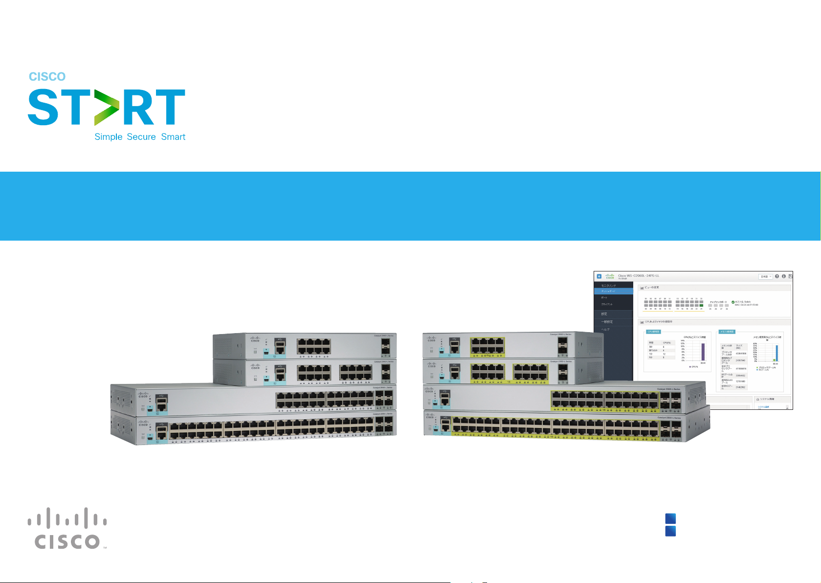
Cisco Catalyst 2960-L Series
Easy Setup Guide
You can easily set up your switch
in this step-by-step guide.
1
Connecting PC to Switch
2
Configuring Switch
Page 2
1
Connecting PC to Switch
1
Connecting PC to Switch
1-1 Before You Begin
Before you begin the installation, make sure that you have the following equipment:
●
Catalyst 2960-L (the switch)
●
Ethernet Cable
●
AC Power Cord
●
PC
Make sure that nothing is connected to the switch and your PC settings are
configured to use DHCP.
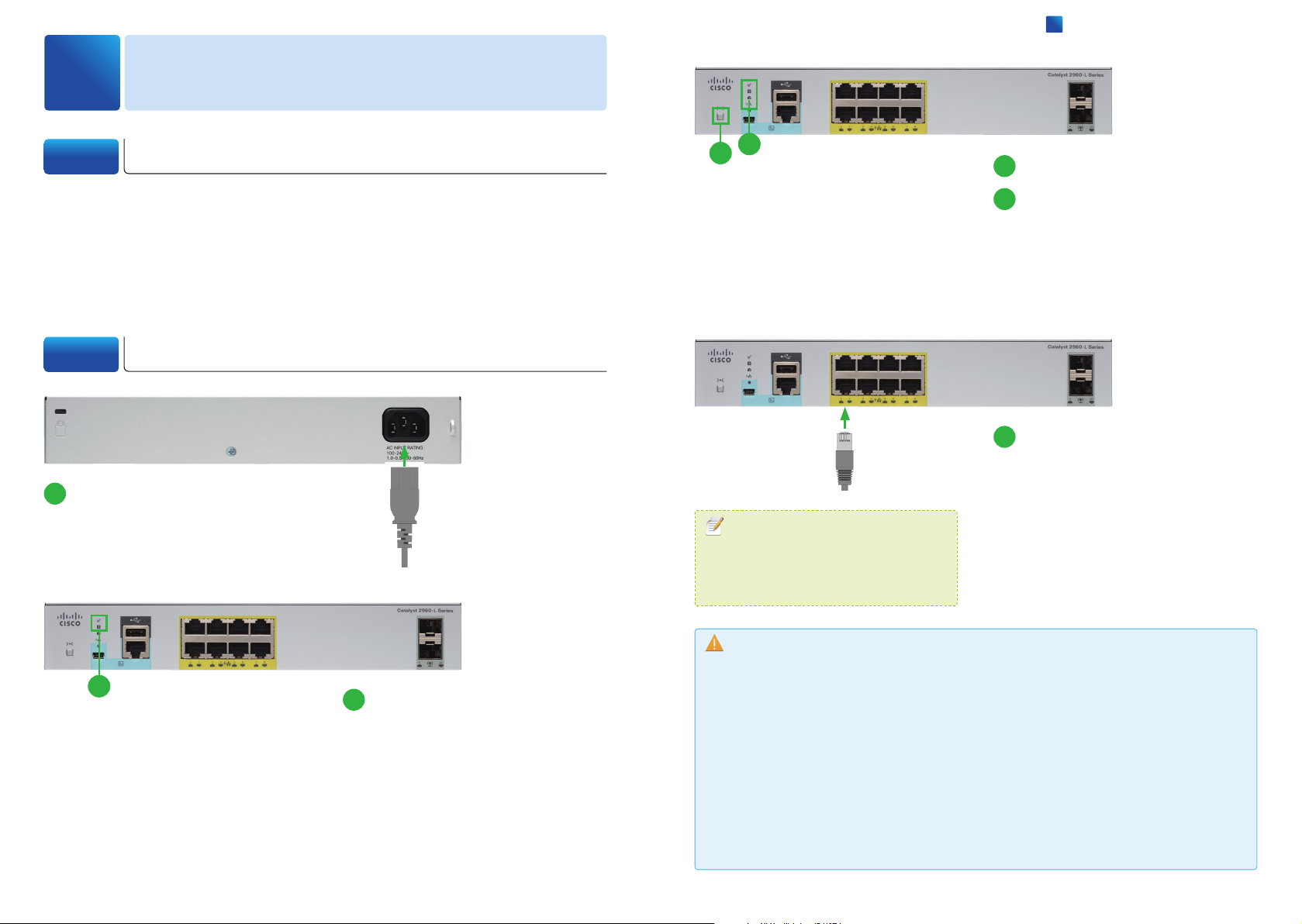
1-2 Connecting PC to Switch
Connect the AC power cord to the
1
AC power connector of the switch
and a grounded AC outlet.
Power the switch.
4
3
MEMO
You can confirm the connection by the
"ping 10.0.0.1" command from your PC
to the switch.
Press and hold the Mode button.
3
Confirm that all the LEDs turn
4
green.
Press the Mode button when the SYST
and STAT LED turn green, hold the Mode
button until all the LEDs next to the Mode
button turn green.
Connect the Ethernet cable to the
5
Ethernet port of the switch, and
the other end of the cable to the
Ethernet port on your PC.
Wait until the port LEDs on the switch and
your PC are green or blinking green. Green
LEDs indicate a successful connection.
Caution
At step
2
Confirm that the SYST LED and
2
STAT LED are solid green.
After the switch powers on, it begins
the power-on self-test (POST). During
POST, the each LED blinks. When POST is
completed, the SYST LED and STAT LED
turn solid green.
POST, reconnect the AC power cord to the switch AC power connector and a grounded AC
outlet. Nevertheless the SYST LED does not turn solid green, or turns amber, contact your
Cisco representative or reseller.
At step
Blinking LEDs indicate that the switch is already configured and cannot go into Express Setup
mode.
At step
RJ-45 console port. The RJ-45 Ethernet ports are numbered 1 to 8 on the 8-port model, 1 to
16 on the 16-port model, 1 to 24 on the 24-port model, 1 to 48 on the 48-port model.
❷
, if the SYST LED does not turn solid green, or turns amber, the switch failed the
❹
, if the LEDs next to the Mode button blink when you press the button, release it.
❺
, the switch port to connect an Ethernet cable is the RJ-45 Ethernet port, not the
Cisco Catalyst 2960-L Series Easy Setup Guide
Page 3
2
Configuring Switch
2-1 Before You Begin
Before you begin the configuration, make sure that you have the following information.
●
IP Address of the Default Gateway (Router)
●
IP Address and Subnet Mask for the Switch
2
Configuring Switch
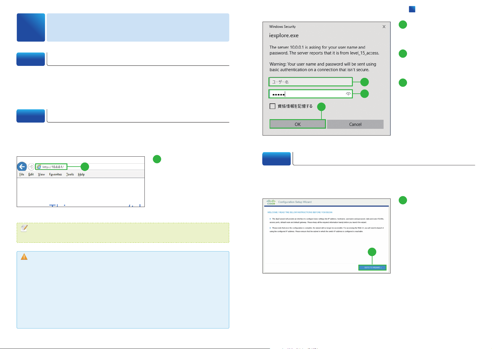
Enter the default
2
username "cisco" in the
[Username].
Enter the default
3
password "cisco" in the
[Password].
2
3
4
Click [OK].
4
The Configuration Setup Wizard
window appears.
2-2
When you first set up the switch, use the Configuration Setup Wizard to enter the
initial IP information. Launch a Web browser on your PC, and log in to the Web UI.
MEMO
The switch has a default IP address "10.0.0.1" and a secondary IP address "10.0.0.3".
Caution
If the authentication dialog box does not appear, make sure that:
・
All the LEDs next to the Mode button turn green.
・
You
・
Any pop-up blockers or proxy settings on your browser are disabled and that any
wireless client is disabled on your PC or laptop.
・
Your PC settings use DHCP. During the Express Setup mode, the switch acts as a DHCP
server. If your PC has a static IP address, temporarily configure your PC settings to use DHCP.
Logging in to Configuration Setup Wizard
Enter the IP address
1
1
connect a straight-through cable to an Ethernet port on the switch and the PC.
"10.0.0.1" into a web
browser address bar, and
press Enter key.
The authentication dialog box
appears.
2-3 Basic Configuration
After logging in to the Web UI, the Configuration Setup Wizard automatically appears
to help you perform initial configuration.
Click [GO TO WIZARD].
1
The BASIC CONFIGURATION
window appears.
1
Cisco Catalyst 2960-L Series Easy Setup Guide
Page 4
2
Configuring Switch
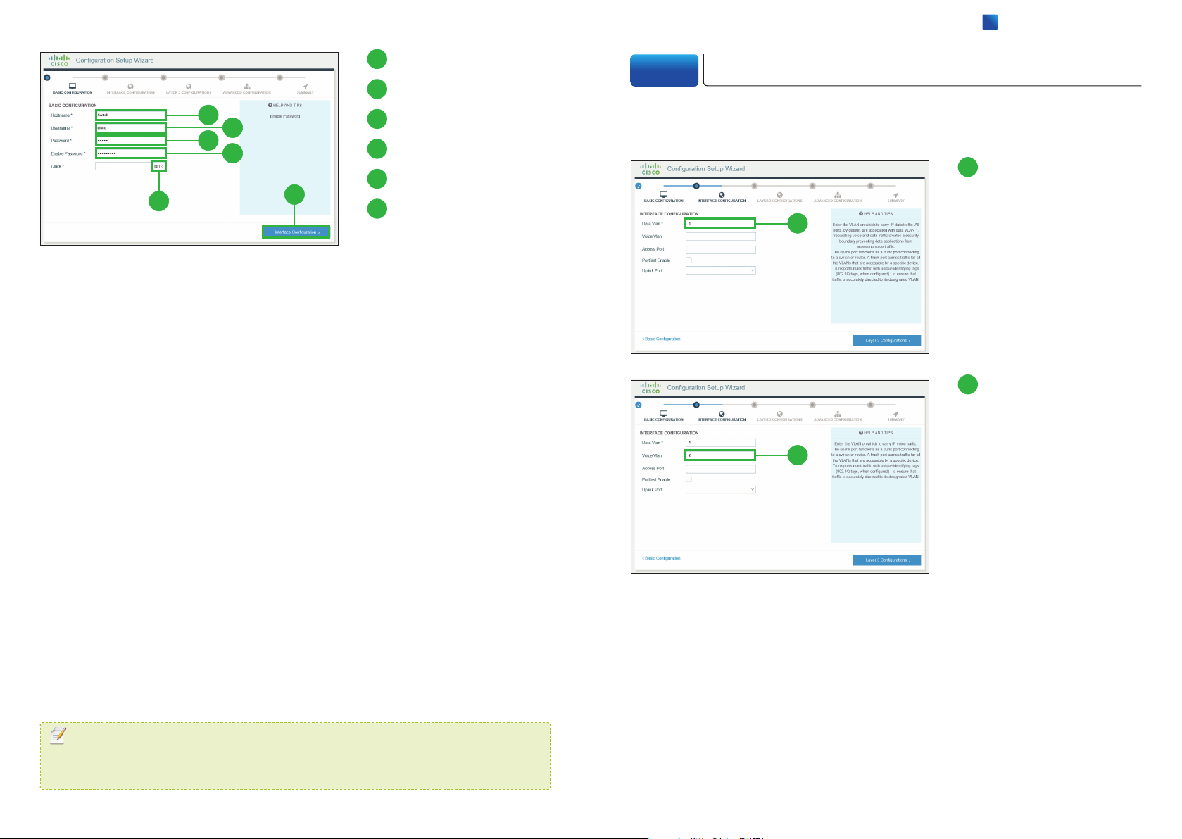
Enter a Hostname.
2
2-4 Interface Configuration
Enter a Username.
3
2
3
4
5
6
7
Enter a Password.
4
Enter a Enable Password.
5
Select the time and date.
6
Click [Interface
7
Configuration].
The INTERFACE
CONFIGURATION window
appears.
Configure the interface information. As a minimum information in order to connect the
switch to the network, the [Data Vlan] field is required.
Enter a Data VLAN ID.
1
By default, the VLAN ID assigned
1
2
to the management interface for
your switch is 1.
Enter a Voice VLAN ID.
2
You can skip this step if your
network does not use a VLAN
for voice traffic.
MEMO
❺
The
[Enable Password] controls access to the privileged EXEC mode in the CLI (Command
Line Interface).
Cisco Catalyst 2960-L Series Easy Setup Guide
Page 5
Select Access Ports.
3
You can skip this step if you want
to use all the RJ-45 Ethernet
ports as access ports.
2
Configuring Switch
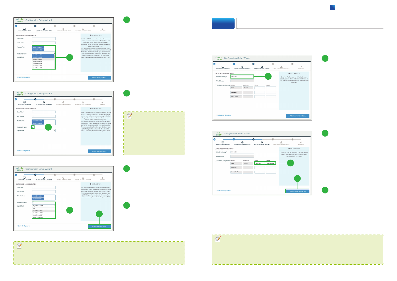
2-5 Layer 3 Configuration
Configure the Layer 3 information. As a minimum information in order to connect the
switch to the network, the [Default Gateway] field is required.
3
Enter the IP address of
1
the Default Gateway.
1
Click [PortFast Enable].
4
You can skip this step.
MEMO
4
The PortFast immediately
brings ports to the forwarding
state from a blocking state,
bypassing the listening and
learning states.
Select Uplink Ports.
5
The uplink port functions as a
trunk port connecting to a switch
or router. You can skip this step.
Enter the IP address
2
and subnet mask for
the switch in the [N e w
IP] and [Subnet] of
2
3
[VlanX] row.
You can configure only one L3
interface on the switch.
Click [Advanced
3
]
Configuration
.
Click [Layer 3
6
5
MEMO
You can configure each ports in the Web UI or CLI (Command Line Interface) after
completing the Configuration Setup Wizard.
6
Configurations]
The LAYER 3 CONFIGURATION
window appears.
The ADVANCED
CONFIGURATION window
appears.
MEMO
The step ❷ is not required, but recommended. By assigning an IP address to the
switch here, you can easily access to the Web UI by entering the IP address into a web
browser address bar, after completing the Configuration Setup Wizard.
Cisco Catalyst 2960-L Series Easy Setup Guide
Page 6
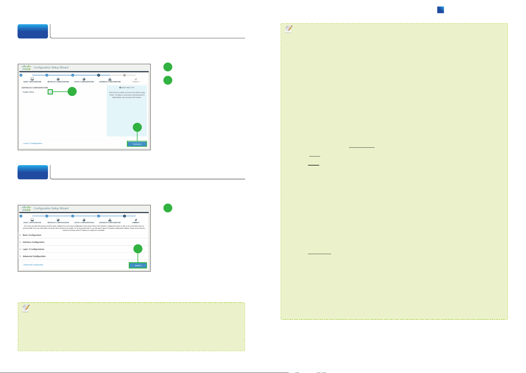
2
Configuring Switch
2-6 Advanced Configuration
Configure the advanced information.
Click [Enable Telnet].
1
Click [Summary].
2
1
The SUMMARY window
appears.
2
2-7 Confirming Settings
Review the settings that you configured, save and enable them on the switch.
Click [Submit].
1
The Redirecting pop-up window
appears. Connect the switch to
your network.
1
MEMO
If you want to reconfigure the siwtch, you must return the switch to the factory default
settings. You can reset the switch in the CLI (Command Line Interface). In order to
access to the CLI, the following environments are required.
・
The terminal-emulation program such as Tera Term, PuTTY, Windows Command
Prompt.
・
Connecting the switch and PC directly by the console cable or remotely through
network.
The example below is the commands to reset in case of using Windows Command
Prompt to connect to the switch with Telnet. Bold text indicates commands entered.
C:\Windows\system32>telnet 10.10.10.2
Username: cisco
Password: cisco
cisco#erase startup-config
Erasing the nvram filesystem will remove all configuration files! Continue? [confirm]
[OK]
Erase of nvram: complete
The example below is the commands to reset in case of connecting to the switch by
the console cable and using Tera Term. Bold text indicates commands entered.
cisco>enable
Password: cisco1234
cisco#erase startup-config
Erasing the nvram filesystem will remove all configuration files! Continue? [confirm]
[OK]
Erase of nvram: complete
*Enter the username of the step 2-3
*Enter the password of the step 2-3
*Enter the enable password of the step 2-3
*Enter the IP address of the step 2-5
❸
❹
❺
❷
MEMO
The switch has a new IP address after configuration (the IP address of the step 2-5 ❷).
Your PC still has an IP address which was assigned by the switch during the Express
Setup mode and needs to have an appropriate IP address to reach the new IP address
of the switch. To do so, simply restart your PC.
When the "Erase of nvram: completemessage is shown, reboot the switch by
entering the "reload" command or reconnecting the AC power cord.
Cisco Catalyst 2960-L Series Easy Setup Guide
Page 7
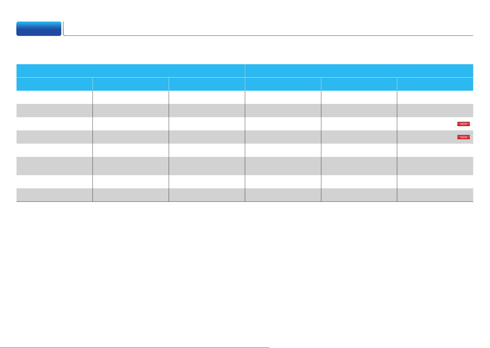
Appendix Transition Guide Settings
The Cisco Catalyst 2960-L Series Switches are ideal for the replacement of the existing Cisco Catalyst Switches, especially Cisco Catalyst 2960-C/SF/S/Plus Series LAN Lite models.
You can upgrade these Fast Ethernet switches to Gigabit Ethernet switches without impairing their functions.
Legacy Models Current Models
Catalyst 2960-C Catalyst 2960-SF Catalyst 2960-S Catalyst 2960-Plus Catalyst 2960-X Catalyst 2960-L
WS-C2960C-8TC-S - - - - WS-C2960L-8TS-LL
- - - - - WS-C2960L-8PS-LL
- - - - - WS-C2960L-16TS-LL
- - - - - WS-C2960L-16PS-LL
- WS-C2960S-F24TS-S WS-C2960S-24TS-S WS-C2960+24TC-S WS-C2960X-24TS-LL WS-C2960L-24TS-AP
- - -
- WS-C2960S-F48TS-S WS-C2960S-48TS-S WS-C2960+48TC-S WS-C2960X-48TS-LL WS-C2960L-48TS-AP
- - - WS-C2960+48PST-S - WS-C2960L-48PS-AP
WS-C2960+24LC-S
WS-C2960+24PC-S
- WS-C2960L-24PS-AP
© 2016 Cisco and/or its affiliates. All rights reserved. Cisco and the Cisco logo are trademarks or registered trademarks of Cisco and/or its affiliates in the U.S. and other countries. To
view a list of Cisco trademarks, go to this URL: www.cisco.com/go/trademarks. Third-party trademarks mentioned are the property of their respective owners. The use of the word
partner does not imply a partnership relationship between Cisco and any other company. (1110R)
 Loading...