

Page 1

Catalyst 2955 Hardware Installation
Guide
November 2004
Corporate Headquarters
Cisco Systems, Inc.
170 West Tasman Drive
San Jose, CA 95134-1706
USA
http://www.cisco.com
Tel: 408 526-4000
800 553-NETS (6387)
Fax: 408 526-4100
Customer Order Number: DOC-7814944=
Text Part Number: 78-14944-03
Page 2

THE SPECIFICATIONS AND INFORMATION REGARDING THE PRODUCTS IN THIS MANUAL ARE SUBJECT TO CHANGE WITHOUT
NOTICE. ALL STATEMENTS, INFORMATION, AND RECOMMENDATIONS IN THIS MANUAL ARE BELIEVED TO BE ACCURATE BUT
ARE PRESENTED WITHOUT WARRANTY OF ANY KIND, EXPRESS OR IMPLIED. USERS MUST TAKE FULL RESPONSIBILITY FOR
THEIR APPLICATION OF ANY PRODUCTS.
THE SOFTWARE LICENSE AND LIMITED WARRANTY FOR THE ACCOMPANYING PRODUCT ARE SET FORTH IN THE INFORMATION
PACKET THAT SHIPPED WITH THE PRODUCT AND ARE INCORPORATED HEREIN BY THIS REFERENCE. IF YOU ARE UNABLE TO
LOCATE THE SOFTWARE LICENSE OR LIMITED WARRANTY, CONTACT YOUR CISCO REPRESENTATIVE FOR A COPY.
The following information is for FCC compliance of Class A devices: This equipment has been tested and found to comply with the limits for a Class
A digital device, pursuant to part 15 of the FCC rules. These limits are designed to provide reasonable protection against harmful interference when
the equipment is operated in a commercial environment. This equipment generates, uses, and can radiate radio-frequency energy and, if not installed
and used in accordance with the instruction manual, may cause harmful interference to radio communications. Operation of this equipment in a
residential area is likely to cause harmful interference, in which case users will be required to correct the interference at their own expense.
The following information is for FCC compliance of Class B devices: The equipment described in this manual generates and may radiate
radio-frequency energy. If it is not installed in accordance with Cisco’s installation instructions, it may cause interference with radio and television
reception. This equipment has been tested and found to comply with the limits for a Class B digital device in accordance with the specifications in
part 15 of the FCC rules. These specifications are designed to provide reasonable protection against such interference in a residential installation.
However, there is no guarantee that interference will not occur in a particular installation.
Modifying the equipment without Cisco’s written authorization may result in the equipment no longer complying with FCC requirements for Class
A or Class B digital devices. In that event, your right to use the equipment may be limited by FCC regulations, and you may be required to correct
any interference to radio or television communications at your own expense.
You can determine whether your equipment is causing interference by turning it off. If the interference stops, it was probably caused by the Cisco
equipment or one of its peripheral devices. If the equipment causes interference to radio or television reception, try to correct the interference by
using one or more of the following measures:
• Turn the television or radio antenna until the interference stops.
• Move the equipment to one side or the other of the television or radio.
• Move the equipment farther away from the television or radio.
• Plug the equipment into an outlet that is on a different circuit from the television or radio. (That is, make certain the equipment and the television
or radio are on circuits controlled by different circuit breakers or fuses.)
Modifications to this product not authorized by Cisco Systems, Inc. could void the FCC approval and negate your authority to operate the product.
The Cisco implementation of TCP header compression is an adaptation of a program developed by the University of California, Berkeley (UCB) as
part of UCB’s public domain version of the UNIX operating system. All rights reserved. Copyright © 1981, Regents of the University of California.
NOTWITHSTANDING ANY OTHER WARRANTY HEREIN, ALL DOCUMENT FILES AND SOFTWARE OF THESE SUPPLIERS ARE
PROVIDED “AS IS” WITH ALL FAULTS. CISCO AND THE ABOVE-NAMED SUPPLIERS DISCLAIM ALL WARRANTIES, EXPRESSED
OR IMPLIED, INCLUDING, WITHOUT LIMITATION, THOSE OF MERCHANTABILITY, FITNESS FOR A PARTICULAR PURPOSE AND
NONINFRINGEMENT OR ARISING FROM A COURSE OF DEALING, USAGE, OR TRADE PRACTICE.
IN NO EVENT SHALL CISCO OR ITS SUPPLIERS BE LIABLE FOR ANY INDIRECT, SPECIAL, CONSEQUENTIAL, OR INCIDENTAL
DAMAGES, INCLUDING, WITHOUT LIMITATION, LOST PROFITS OR LOSS OR DAMAGE TO DATA ARISING OUT OF THE USE OR
INABILITY TO USE THIS MANUAL, EVEN IF CISCO OR ITS SUPPLIERS HAVE BEEN ADVISED OF THE POSSIBILITY OF SUCH
DAMAGES.
Page 3

CCSP, the Cisco Square Bridge logo, Follow Me Browsing, and StackWise are trademarks of Cisco Systems, Inc.; Changing the Way We Work, Live,
Play, and Learn, and iQuick Study are service marks of Cisco Systems, Inc.; and Access Registrar, Aironet, ASIST, BPX, Catalyst, CCDA, CCDP, CCIE,
CCIP, CCNA, CCNP, Cisco, the Cisco Certified Internetwork Expert logo, Cisco IOS, Cisco Press, Cisco Systems, Cisco Systems Capital, the Cisco
Systems logo, Cisco Unity, Empowering the Internet Generation, Enterprise/Solver, EtherChannel, EtherFast, EtherSwitch, Fast Step, FormShare,
GigaDrive, GigaStack, HomeLink, Internet Quotient, IOS, IP/TV, iQ Expertise, the iQ logo, iQ Net Readiness Scorecard, LightStream, Linksys,
MeetingPlace, MGX, the Networkers logo, Networking Academy, Network Registrar, Pack et, PIX, Post-Routing, Pre-Routing, ProConnect, RateMUX,
ScriptShare, SlideCast, SMARTnet, StrataView Plus, SwitchProbe, TeleRouter, The Fastest Way to Increase Your Internet Quotient, TransPath, and VCO
are registered trademarks of Cisco Systems, Inc. and/or its affiliates in the United States and certain other countries.
All other trademarks mentioned in this document or Website are the property of their respective owners. The use of the word partner does not imply a
partnership relationship between Cisco and any other company. (0411R)
Catalyst 2955 Hardware Installation Guide
Copyright © 2003-2005 Cisco Systems, Inc. All rights reserved.
Page 4

Page 5

CONTENTS
Cisco Limited 5-Year Hardware and 1-Year Software Warranty Terms xiii
Preface xvii
Audience xvii
Purpose xvii
Conventions xviii
Related Publications xxvi
Obtaining Documentation xxvi
Cisco.com xxvii
Documentation DVD xxvii
Ordering Documentation xxvii
Documentation Feedback xxviii
CHAPTER
78-14944-03
Cisco Product Security Overview xxviii
Reporting Security Problems in Cisco Products xxix
Obtaining Technical Assistance xxx
Cisco Technical Support Website xxx
Submitting a Service Request xxxi
Definitions of Service Request Severity xxxi
Obtaining Additional Publications and Information xxxii
1 Configuring the Switch with the CLI-Based Setup Program 1-1
Taking Out What You Need 1-2
Connecting to a Power Source 1-2
Connecting to the Console Port 1-4
Catalyst 2955 Hardware Installation Guide
v
Page 6

Contents
Starting the Terminal-Emulation Software 1-5
Entering the Initial Configuration Information 1-6
IP Settings 1-7
Completing the Setup Program 1-7
CHAPTER
2 Overview 2-1
Features 2-1
Front-Panel Description 2-3
Warning Labels 2-5
10/100 Ports 2-6
10/100/1000 Ports 2-7
100BASE-FX Ports 2-8
100BASE-LX Ports 2-8
Power and Relay Connector 2-8
Console Port 2-10
LEDs 2-10
Rear-Panel Description 2-17
Catalyst 2955 Switch Power Converter 2-17
Management Options 2-19
Power Status LEDs 2-12
10/100 Port Status LEDs 2-13
Uplink Port Status LEDs 2-14
Alarm Relay LEDs 2-16
CHAPTER
vi
3 Installation 3-1
Preparing for Installation 3-2
Warnings 3-2
EMC Regulatory Statements 3-6
U.S.A. 3-6
Catalyst 2955 Hardware Installation Guide
78-14944-03
Page 7

Class A Notice for Taiwan and Other Traditional Chinese Markets 3-6
VCCI Class A Notice for Japan 3-7
Class A Warning for Korea 3-7
Class A Warning for Hungary 3-8
Installation Guidelines 3-8
Verifying Package Contents 3-9
Applying the Switch Protective Liner 3-10
Verifying Switch Operation 3-11
Connecting a PC or a Terminal to the Console Port 3-11
Powering On the Switch and Running POST 3-13
Grounding the Switch 3-15
Wiring the DC Power Source 3-17
Add the Ferrite to the Power and Relay Connector Wiring 3-24
Attach the Power and Relay Connector to the Switch 3-25
Power On the Switch 3-27
Running POST 3-27
Contents
78-14944-03
Connecting the Switch to the Power Converter 3-29
Installing the Power Converter on a DIN Rail 3-30
Connecting the Power Converter to the Power and Relay Connector 3-32
Connecting the Power Converter to an AC Power Source 3-35
Preparing the AC Power Cord 3-35
Connecting the AC Power Cord to the Power Converter 3-37
Connecting the Power Converter to a DC Power Source 3-41
Applying Power to the Power Converter 3-46
Removing the Power Converter from a DIN Rail 3-46
Wiring the External Alarm Device Relays 3-48
Installing the Switch on a DIN Rail 3-52
Installing the Switch in a Rack 3-57
Removing the Switch from a DIN Rail or a Rack 3-59
Catalyst 2955 Hardware Installation Guide
vii
Page 8

Contents
Connecting to 10/100 and 10/100/1000 Ports 3-62
Connecting to 100BASE-FX MM Ports 3-65
Connecting to 100BASE-LX SM Ports 3-67
Where to Go Next 3-69
CHAPTER
4 Installation in a Hazardous Environment 4-1
Preparing for Installation 4-2
Warnings 4-2
EMC Regulatory Statements 4-8
U.S.A. 4-8
Class A Notice for Taiwan and Other Traditional Chinese Markets 4-8
VCCI Class A Notice for Japan 4-9
Class A Warning for Korea 4-9
Class A Warning for Hungary 4-10
European Zone 2 Certification 4-10
Installation Guidelines 4-11
Verifying Package Contents 4-12
Applying the Switch Protective Liner 4-13
Verifying Switch Operation 4-14
Connecting a PC or a Terminal to the Console Port 4-14
Powering On the Switch and Running POST 4-16
Grounding the Switch 4-18
Wiring the DC Power Source 4-21
Add the Ferrite to the Power and Relay Connector Wiring 4-27
Attach the Power and Relay Connector to the Switch 4-28
Power On the Switch 4-30
Running POST 4-30
viii
Wiring the External Alarm Device Relays 4-32
Installing the Switch on a DIN Rail 4-37
Catalyst 2955 Hardware Installation Guide
78-14944-03
Page 9

Installing the Switch in a Rack 4-42
Removing the Switch from a DIN Rail or a Rack 4-45
Connecting to 10/100 and 10/100/1000 Ports 4-47
Connecting to 100BASE-FX MM Ports 4-50
Connecting to 100BASE-LX SM Ports 4-52
Where to Go Next 4-54
Contents
CHAPTER
APPENDIX
APPENDIX
5 Troubleshooting 5-1
Understanding POST Results 5-2
Diagnosing Problems 5-3
A Technical Specifications A-1
B Connectors and Cables B-1
Connector Specifications B-1
10/100 and 10/100 /1000 Ports B-2
100BASE-FX Ports B-3
100BASE-LX Ports B-3
Power and Relay Connector B-4
Console Port B-5
Cable and Adapter Specifications B-5
Two Twisted-Pair Cable Pinouts B-6
Four Twisted-Pair Cable Pinouts for 10/100 Ports B-6
Four Twisted-Pair Cable Pinouts for 1000BASE-T Ports B-8
Cable and Adapter Pinouts B-9
Connecting to a PC B-9
Connecting to a Terminal B-10
Identifying a Crossover Cable B-11
78-14944-03
Catalyst 2955 Hardware Installation Guide
ix
Page 10

Contents
APPENDIX
C Translated Safety Warnings C-1
Work During Lightning Activity C-1
Power and Relay Connector C-3
Switch Installation In Hazardous Location C-7
Safe Operating Voltage Range Warning C-9
Switch Relays Warning C-11
Remove Power Before Disconnecting C-15
“Open Type” Equipment C-18
Grounded Equipment C-22
Console Cable Connection C-24
Overtemperature Warning C-27
Class I, Division 2, Hazardous Location C-29
Twisted-pair Supply Wires C-32
Pollution Degree 2 Industrial Environment C-33
Port Connection C-35
Installation Instructions C-38
Service Personnel Warning C-39
Stacking the Chassis Warning C-41
Ground Connection Warning C-42
SELV-IEC 60950 DC Power Supply C-44
Jewelry Removal Warning C-45
Product Disposal Warning C-47
Class 1 Laser Product C-49
Class 1 LED Product C-50
Laser Radiation C-52
Laser Viewing Warning C-54
Laser Beam Exposure C-56
Catalyst 2955 Hardware Installation Guide
x
78-14944-03
Page 11

I
NDEX
Contents
Chassis Warning for Rack-Mounting and Servicing C-58
Grounded Equipment Warning C-66
Qualified Personnel Warning C-68
Restricted Area C-69
Chassis Power Connection C-72
Exposed DC Power Wire Warning C-75
78-14944-03
Catalyst 2955 Hardware Installation Guide
xi
Page 12

Contents
xii
Catalyst 2955 Hardware Installation Guide
78-14944-03
Page 13

Cisco Limited 5-Year Hardware and
1-Year Software Warranty Terms
There are special terms applicable to your hardware warranty and various services
that you can use during the warranty period. Your formal Warranty Statement,
including the warranties and license agreements applicable to Cisco software, is
available on Cisco.com. Follow these steps to access and download the Cisco
Information Packet and your warranty and license agreements from Cisco.com.
1. Launch your browser, and go to this URL:
http://www.cisco.com/univercd/cc/td/doc/es_inpck/cetrans.htm
78-14944-03
The Warranties and License Agreements page appears.
2. To read t he Cisco Information Packet, follow these steps:
a. Click the Information Packet Number field, and make sure that the part
number 78-5235-03A0 is highlighted.
b. Select the language in which you would like to read the document.
c. Click Go.
The Cisco Limited Warranty and Software License page from the
Information Packet appears.
d. Read the document online, or click the PDF icon to download and print
the document in Adobe Portable Document Format (PDF).
Catalyst 2955 Hardware Installation Guide
xiii
Page 14

Cisco Limited 5-Year Hardware and 1-Year Software Warranty Terms
Note You must have Adobe Acrobat Reader to view and print PDF
files. You can download the reader from Adobe’s website:
http://www.adobe.com
3. To read translated and localized warranty information about your product,
follow these steps:
a. Enter this part number in the Warranty Document Number field:
78-13712-01C0
b. Select the language in which you would like to read the document.
c. Click Go.
The Cisco warranty page appears.
d. Read the document online, or click the PDF icon to download and print
the document in Adobe Portable Document Format (PDF).
You can also contact the Cisco service and support website for assistance:
http://www.cisco.com/public/Support_root.shtml.
xiv
Duration of Hardware Warranty
Five (5) Years
Duration of Software Warranty
One (1) Year
Replacement, Repair, or Refund Policy for Hardware
Cisco or its service center will use commercially reasonable efforts to ship a
replacement part for delivery within fifteen (15) working days after receipt of the
defective product at Cisco’s site. Actual delivery times of replacement products
can vary, depending on the customer location.
Cisco reserves the right to refund the purchase price as its exclusive warranty
remedy.
To Receive a Return Materials Authorization (RMA) Number
Contact the company from whom you purchased the product. If you purchased the
product directly from Cisco, contact your Cisco Sales and Service Representative.
Catalyst 2955 Hardware Installation Guide
78-14944-03
Page 15

Cisco Limited 5-Year Hardware and 1-Year Software Warranty Terms
Complete the information below, and keep it for reference.
Company product purchased from
Company telephone number
Product model number
Product serial number
Maintenance contract number
78-14944-03
Catalyst 2955 Hardware Installation Guide
xv
Page 16

Cisco Limited 5-Year Hardware and 1-Year Software Warranty Terms
xvi
Catalyst 2955 Hardware Installation Guide
78-14944-03
Page 17

Audience
Purpose
Preface
This guide is for the networking or computer technician responsible for installing
a Catalyst 2955 switch, hereafter referred to as the switch. We assume that you are
familiar with the concepts and terminology of Ethernet and local area networking.
78-14944-03
This guide describes the hardware features of Catalyst 2955 switch. It describes
the physical and performance characteristics of the switch, explains how to install
a switch, and provides troubleshooting information.
This guide does not describe how to configure software features on your switch
or describe the Catalyst 2955-specific system messages that you might encounter.
It also does not provide information about command-line interface (CLI)
commands that have been created or changed for use by the switch. For more
information, see the software configuration, the system message, and the
command reference guides for the switch.
Catalyst 2955 Hardware Installation Guide
xvii
Page 18

Conventions
Conventions
This publication uses these conventions and symbols for notes, cautions, and
warnings:
Note Means reader take note. Notes contain helpful suggestions or references to
materials not contained in this manual.
Caution Means reader be careful. In this situation, you might do something that could
result in equipment damage or loss of data.
Preface
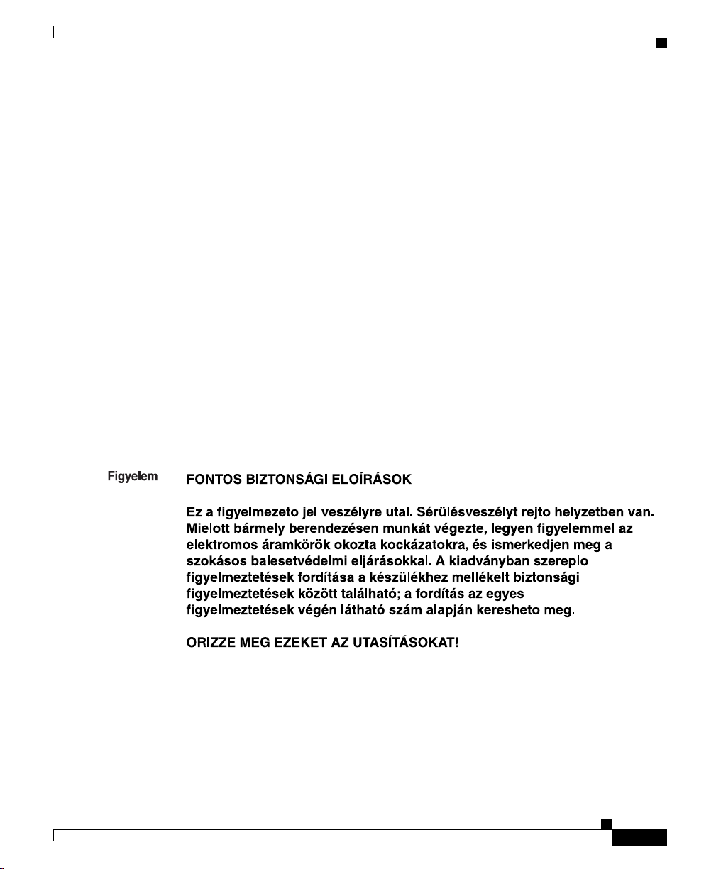
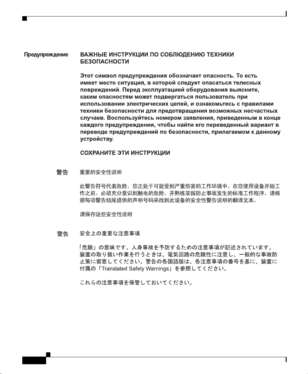
Warning
Waarschuwing
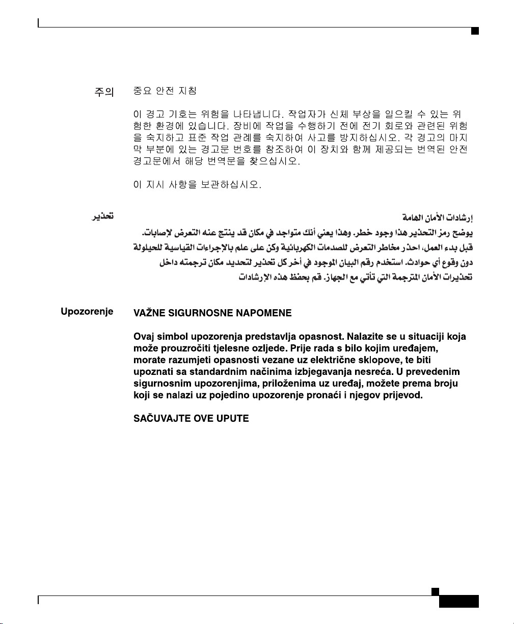
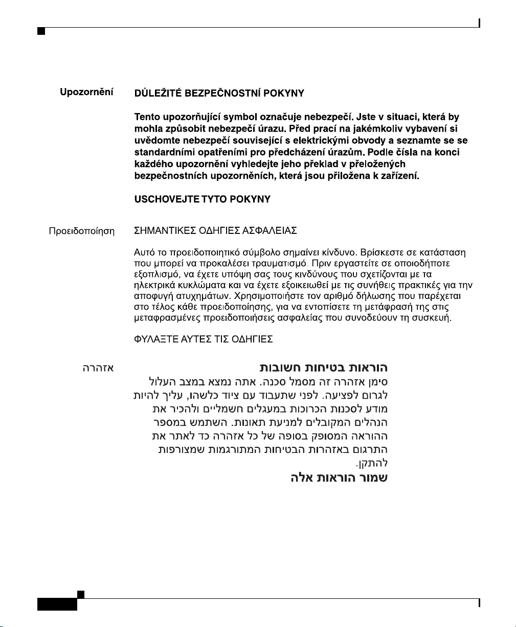
IMPORTANT SAFETY INSTRUCTIONS
This warning symbol means danger. You are in a situation that could cause
bodily injury. Before you work on any equipment, be aware of the hazards
involved with electrical circuitry and be familiar with standard practices for
preventing accidents. Use the statement number provided at the end of each
warning to locate its translation in the translated safety warnings that
accompanied this device.
SAVE THESE INSTRUCTIONS
BELANGRIJKE VEILIGHEIDSINSTRUCTIES
Dit waarschuwingssymbool betekent gevaar. U verkeert in een situatie die
lichamelijk letsel kan veroorzaken. Voordat u aan enige apparatuur gaat
werken, dient u zich bewust te zijn van de bij elektrische schakelingen
betrokken risico's en dient u op de hoogte te zijn van de standaard praktijken
om ongelukken te voorkomen. Gebruik het nummer van de verklaring
onderaan de waarschuwing als u een vertaling van de waarschuwing die bij
het apparaat wordt geleverd, wilt raadplegen.
BEWAAR DEZE INSTRUCTIES
Statement 1071
xviii
Catalyst 2955 Hardware Installation Guide
78-14944-03
Page 19

Preface
Conventions
Varoitus
Attention
Warnung
TÄRKEITÄ TURVALLISUUSOHJEITA
Tämä varoitusmerkki merkitsee vaaraa. Tilanne voi aiheuttaa ruumiillisia
vammoja. Ennen kuin käsittelet laitteistoa, huomioi sähköpiirien
käsittelemiseen liittyvät riskit ja tutustu onnettomuuksien yleisiin
ehkäisytapoihin. Turvallisuusvaroitusten käännökset löytyvät laitteen
mukana toimitettujen käännettyjen turvallisuusvaroitusten joukosta
varoitusten lopussa näkyvien lausuntonumeroiden avulla.
SÄILYTÄ NÄMÄ OHJEET
IMPORTANTES INFORMATIONS DE SÉCURITÉ
Ce symbole d'avertissement indique un danger. Vous vous trouvez dans une
situation pouvant entraîner des blessures ou des dommages corporels. Avant
de travailler sur un équipement, soyez conscient des dangers liés aux circuits
électriques et familiarisez-vous avec les procédures couramment utilisées
pour éviter les accidents. Pour prendre connaissance des traductions des
avertissements figurant dans les consignes de sécurité traduites qui
accompagnent cet appareil, référez-vous au numéro de l'instruction situé à la
fin de chaque avertissement.
CONSERVEZ CES INFORMATIONS
WICHTIGE SICHERHEITSHINWEISE
78-14944-03
Dieses Warnsymbol bedeutet Gefahr. Sie befinden sich in einer Situation, die
zu Verletzungen führen kann. Machen Sie sich vor der Arbeit mit Geräten mit
den Gefahren elektrischer Schaltungen und den üblichen Verfahren zur
Vorbeugung vor Unfällen vertraut. Suchen Sie mit der am Ende jeder Warnung
angegebenen Anweisungsnummer nach der jeweiligen Übersetzung in den
übersetzten Sicherheitshinweisen, die zusammen mit diesem Gerät
ausgeliefert wurden.
BEWAHREN SIE DIESE HINWEISE GUT AUF.
Catalyst 2955 Hardware Installation Guide
xix
Page 20

Conventions
Preface
Avvertenza
Advarsel
Aviso
IMPORTANTI ISTRUZIONI SULLA SICUREZZA
Questo simbolo di avvertenza indica un pericolo. La situazione potrebbe
causare infortuni alle persone. Prima di intervenire su qualsiasi
apparecchiatura, occorre essere al corrente dei pericoli relativi ai circuiti
elettrici e conoscere le procedure standard per la prevenzione di incidenti.
Utilizzare il numero di istruzione presente alla fine di ciascuna avvertenza per
individuare le traduzioni delle avvertenze riportate in questo documento.
CONSERVARE QUESTE ISTRUZIONI
VIKTIGE SIKKERHETSINSTRUKSJONER
Dette advarselssymbolet betyr fare. Du er i en situasjon som kan føre til skade
på person. Før du begynner å arbeide med noe av utstyret, må du være
oppmerksom på farene forbundet med elektriske kretser, og kjenne til
standardprosedyrer for å forhindre ulykker. Bruk nummeret i slutten av hver
advarsel for å finne oversettelsen i de oversatte sikkerhetsadvarslene som
fulgte med denne enheten.
TA VARE PÅ DISSE INSTRUKSJONENE
INSTRUÇÕES IMPORTANTES DE SEGURANÇA
Este símbolo de aviso significa perigo. Você está em uma situação que poderá
ser causadora de lesões corporais. Antes de iniciar a utilização de qualquer
equipamento, tenha conhecimento dos perigos envolvidos no manuseio de
circuitos elétricos e familiarize-se com as práticas habituais de prevenção de
acidentes. Utilize o número da instrução fornecido ao final de cada aviso para
localizar sua tradução nos avisos de segurança traduzidos que acompanham
este dispositivo.
xx
GUARDE ESTAS INSTRUÇÕES
Catalyst 2955 Hardware Installation Guide
78-14944-03
Page 21
Preface
Conventions
¡Advertencia!
Varning!
INSTRUCCIONES IMPORTANTES DE SEGURIDAD
Este símbolo de aviso indica peligro. Existe riesgo para su integridad física.
Antes de manipular cualquier equipo, considere los riesgos de la corriente
eléctrica y familiarícese con los procedimientos estándar de prevención de
accidentes. Al final de cada advertencia encontrará el número que le ayudará
a encontrar el texto traducido en el apartado de traducciones que acompaña
a este dispositivo.
GUARDE ESTAS INSTRUCCIONES
VIKTIGA SÄKERHETSANVISNINGAR
Denna varningssignal signalerar fara. Du befinner dig i en situation som kan
leda till personskada. Innan du utför arbete på någon utrustning måste du vara
medveten om farorna med elkretsar och känna till vanliga förfaranden för att
förebygga olyckor. Använd det nummer som finns i slutet av varje varning för
att hitta dess översättning i de översatta säkerhetsvarningar som medföljer
denna anordning.
SPARA DESSA ANVISNINGAR
78-14944-03
Catalyst 2955 Hardware Installation Guide
xxi
Page 22
Conventions
Preface
xxii
Catalyst 2955 Hardware Installation Guide
78-14944-03
Page 23
Preface
Conventions
78-14944-03
Catalyst 2955 Hardware Installation Guide
xxiii
Page 24
Conventions
Preface
xxiv
Catalyst 2955 Hardware Installation Guide
78-14944-03
Page 25
Preface
Conventions
78-14944-03
Catalyst 2955 Hardware Installation Guide
xxv
Page 26

Related Publications
Related Publications
These documents provide complete information about the switch and are available
from this URL:
http://www.cisco.com/univercd/cc/td/doc/product/lan/cat2950/index.htm
You can order printed copies of documents with a DOC-xxxxxx= number from the
Cisco.com sites and from the telephone numbers listed in the “Ordering
Documentation” section on page xxvii.
• Release Notes for the Catalyst 2950 and 2955 Switches (not orderable but is
available on Cisco.com)
Note Switch requirements and procedures for initial configurations and software
upgrades tend to change and therefore appear only in the release notes. Before
installing, configuring, or upgrading the switch, see the release notes on
Cisco.com for the latest information.
• Catalyst 2950 and Catalyst 2955 Switch Software Configuration Guide
(order number DOC-7811380=)
• Catalyst 2950 and Catalyst 2955 Switch Command Reference (order number
DOC-7811381=)
Preface
• Catalyst 2950 and Catalyst 2955 Switch System Message Guide
(order number DOC-7814233=)
• Catalyst 2950 Switch Hardware Installation Guide (not orderable but
available on Cisco.com)
• Device manager online help (available on the switch)
• Getting Started with Cisco Network Assistant (not orderable but available on
Cisco.com)
Obtaining Documentation
Cisco documentation and additional literature are available on Cisco.com. Cisco
also provides several ways to obtain technical assistance and other technical
resources. These sections explain how to obtain technical information from Cisco
Systems.
Catalyst 2955 Hardware Installation Guide
xxvi
78-14944-03
Page 27

Preface
Cisco.com
You can access the most current Cisco documentation at this URL:
http://www.cisco.com/univercd/home/home.htm
You can access the Cisco website at this URL:
http://www.cisco.com
You can access international Cisco websites at this URL:
http://www.cisco.com/public/countries_languages.shtml
Documentation DVD
Cisco documentation and additional literature are available in a Documentation
DVD package, which may have shipped with your product. The Documentation
DVD is updated regularly and may be more current than printed documentation.
The Documentation DVD package is available as a single unit.
Registered Cisco.com users (Cisco direct customers) can order a Cisco
Documentation DVD (product number DOC-DOCDVD=) from the Ordering tool
or Cisco Marketplace.
Obtaining Documentation
Cisco Ordering tool:
http://www.cisco.com/en/US/partner/ordering/
Cisco Marketplace:
http://www.cisco.com/go/marketplace/
Ordering Documentation
You can find instructions for ordering documentation at this URL:
http://www.cisco.com/univercd/cc/td/doc/es_inpck/pdi.htm
78-14944-03
Catalyst 2955 Hardware Installation Guide
xxvii
Page 28

Documentation Feedback
You can order Cisco documentation in these ways:
• Registered Cisco.com users (Cisco direct customers) can order Cisco product
documentation from the Ordering tool:
http://www.cisco.com/en/US/partner/ordering/
• Nonregistered Cisco.com users can order documentation through a local
account representative by calling Cisco Systems Corporate Headquarters
(California, USA) at 408 526-7208 or, elsewhere in North America, by
calling 1 800 553-NETS (6387).
Documentation Feedback
You can send comments about technical documentation to bug-doc@cisco.com.
You can submit comments by using the response card (if present) behind the front
cover of your document or by writing to the following address:
Cisco Systems
Attn: Customer Document Ordering
170 West Tasman Drive
San Jose, CA 95134-9883
We appreciate your comments.
Preface
Cisco Product Security Overview
Cisco provides a free online Security Vulnerability Policy portal at this URL:
http://www.cisco.com/en/US/products/products_security_vulnerability_policy.ht
ml
From this site, you can perform these tasks:
• Report security vulnerabilities in Cisco products.
• Obtain assistance with security incidents that involve Cisco products.
• Register to receive security information from Cisco.
Catalyst 2955 Hardware Installation Guide
xxviii
78-14944-03
Page 29

Preface
A current list of security advisories and notices for Cisco products is available at
this URL:
http://www.cisco.com/go/psirt
If you prefer to see advisories and notices as they are updated in real time, you
can access a Product Security Incident Response Team Really Simple Syndication
(PSIRT RSS) feed from this URL:
http://www.cisco.com/en/US/products/products_psirt_rss_feed.html
Reporting Security Problems in Cisco Products
Cisco is committed to delivering secure products. We test our products internally
before we release them, and we strive to correct all vulnerabilities quickly. If you
think that you might have identified a vulnerability in a Cisco product, contact
PSIRT:
• Emergencies — security-alert@cisco.com
• Nonemergencies— psirt@cisco.com
Cisco Product Security Overview
78-14944-03
Tip We encourage you to use Pretty Good Privacy (PGP) or a compatible product to
encrypt any sensitive information that you send to Cisco. PSIRT can work from
encrypted information that is compatible with PGP versions 2.x through 8.x.
Never use a revoked or an expired encryption key. The correct public key to use
in your correspondence with PSIRT is the one that has the most recent creation
date in this public key server list:
http://pgp.mit.edu:11371/pks/lookup?search=psirt%40cisco.com&op=index&ex
act=on
In an emergency, you can also reach PSIRT by telephone:
• 1 877 228-7302
• 1 408 525-6532
Catalyst 2955 Hardware Installation Guide
xxix
Page 30

Obtaining Technical Assistance
Obtaining Technical Assistance
For all customers, partners, resellers, and distributors who hold valid Cisco
service contracts, Cisco Technical Support provides 24-hour-a-day,
award-winning technical assistance. The Cisco Technical Support Website on
Cisco.com features extensive online support resources. In addition, Cisco
Technical Assistance Center (TAC) engineers provide telephone support. If you
do not hold a valid Cisco service contract, contact your reseller.
Cisco Technical Support Website
The Cisco Technical Support Website provides online documents and tools for
troubleshooting and resolving technical issues with Cisco products and
technologies. The website is available 24 hours a day, 365 days a year, at this
URL:
http://www.cisco.com/techsupport
Access to all tools on the Cisco Technical Support Website requires a Cisco.com
user ID and password. If you have a valid service contract but do not have a user
ID or password, you can register at this URL:
Preface
xxx
http://tools.cisco.com/RPF/register/register.do
Note Use the Cisco Product Identification (CPI) tool to locate your product serial
number before submitting a web or phone request for service. You can access the
CPI tool from the Cisco Technical Support Website by clicking the Tools &
Resources link under Documentation & Tools. Choose Cisco Product
Identification Tool from the Alphabetical Index drop-down list, or click the
Cisco Product Identification Tool link under Alerts & RMAs. The CPI tool
offers three search options: by product ID or model name; by tree view; or for
certain products, by copying and pasting show command output. Search results
show an illustration of your product with the serial number label location
highlighted. Locate the serial number label on your product and record the
information before placing a service call.
Catalyst 2955 Hardware Installation Guide
78-14944-03
Page 31

Preface
Submitting a Service Request
Using the online TAC Service Request Tool is the fastest way to open S3 and S4
service requests. (S3 and S4 service requests are those in which your network is
minimally impaired or for which you require product information.) After you
describe your situation, the TAC Service Request Tool provides recommended
solutions. If your issue is not resolved using the recommended resources, your
service request is assigned to a Cisco TAC engineer. The TAC Service Request
Tool is located at this URL:
http://www.cisco.com/techsupport/servicerequest
For S1 or S2 service requests or if you do not have Internet access, contact the
Cisco TAC by telephone. (S1 or S2 service requests are those in which your
production network is down or severely degraded.) Cisco TAC engineers are
assigned immediately to S1 and S2 service requests to help keep your business
operations running smoothly.
To open a service request by telephone, use one of the following numbers:
Asia-Pacific: +61 2 8446 7411 (Australia: 1 800 805 227)
EMEA: +32 2 704 55 55
USA: 1 800 553-2447
Obtaining Technical Assistance
For a complete list of Cisco TAC contacts, go to this URL:
http://www.cisco.com/techsupport/contacts
Definitions of Service Request Severity
To ensure that all service requests are reported in a standard format, Cisco has
established severity definitions.
Severity 1 (S1)—Your network is “down,” or there is a critical impact to your
business operations. You and Cisco will commit all necessary resources around
the clock to resolve the situation.
Severity 2 (S2)—Operation of an existing network is severely degraded, or
significant aspects of your business operation are negatively affected by
inadequate performance of Cisco products. You and Cisco will commit full-time
resources during normal business hours to resolve the situation.
Catalyst 2955 Hardware Installation Guide
78-14944-03
xxxi
Page 32

Preface
Obtaining Additional Publications and Information
Severity 3 (S3)—Operational performance of your network is impaired, but most
business operations remain functional. You and Cisco will commit resources
during normal business hours to restore service to satisfactory levels.
Severity 4 (S4)—You require information or assistance with Cisco product
capabilities, installation, or configuration. There is little or no effect on your
business operations.
Obtaining Additional Publications and Information
Information about Cisco products, technologies, and network solutions is
available from various online and printed sources.
• Cisco Marketplace provides a variety of Cisco books, reference guides, and
logo merchandise. Visit Cisco Marketplace, the company store, at this URL:
http://www.cisco.com/go/marketplace/
• Cisco Press publishes a wide range of general networking, training and
certification titles. Both new and experienced users will benefit from these
publications. For current Cisco Press titles and other information, go to Cisco
Press at this URL:
xxxii
http://www.ciscopress.com
• Packet magazine is the Cisco Systems technical user magazine for
maximizing Internet and networking investments. Each quarter, Packet
delivers coverage of the latest industry trends, technology breakthroughs, and
Cisco products and solutions, as well as network deployment and
troubleshooting tips, configuration examples, customer case studies,
certification and training information, and links to scores of in-depth online
resources. You can access Packet magazine at this URL:
http://www.cisco.com/packet
• iQ Magazine is the quarterly publication from Cisco Systems designed to
help growing companies learn how they can use technology to increase
revenue, streamline their business, and expand services. The publication
identifies the challenges facing these companies and the technologies to help
solve them, using real-world case studies and business strategies to help
readers make sound technology investment decisions. You can access iQ
Magazine at this URL:
http://www.cisco.com/go/iqmagazine
Catalyst 2955 Hardware Installation Guide
78-14944-03
Page 33

Preface
Obtaining Additional Publications and Information
• Internet Protocol Journal is a quarterly journal published by Cisco Systems
for engineering professionals involved in designing, developing, and
operating public and private internets and intranets. You can access the
Internet Protocol Journal at this URL:
http://www.cisco.com/ipj
• World-class networking training is available from Cisco. You can view
current offerings at this URL:
http://www.cisco.com/en/US/learning/index.html
78-14944-03
Catalyst 2955 Hardware Installation Guide
xxxiii
Page 34

Obtaining Additional Publications and Information
Preface
xxxiv
Catalyst 2955 Hardware Installation Guide
78-14944-03
Page 35

CHAPTER
1
Configuring the Switch with the CLI-Based Setup Program
This chapter provides a command-line interface (CLI)-based setup procedure for
a standalone switch. For product overview information, see Chapter 2,
“Overview.” Before connecting the switch to a power source, review the safety
warnings in Chapter 3, “Installation.” For procedures on connecting the switch to
a power source, rack-mounting your switch, or connecting to the Ethernet ports,
see Chapter 3, “Installation.”
Caution If you are installing your switch in a hazardous environment, review the safety
warnings in Chapter 4, “Installation in a Hazardous Environment.” For
installation procedures for a hazardous environment, see Chapter 4, “Installation
in a Hazardous Environment.”
78-14944-03
These steps describe how to do a simple installation:
1. Taking Out What You Need, page 1-2
2. Connecting to the Console Port, page 1-4
3. Starting the Terminal-Emulation Software, page 1-5
4. Connecting to a Power Source, page 1-2
5. Entering the Initial Configuration Information, page 1-6
Catalyst 2955 Hardware Installation Guide
1-1
Page 36

Chapter 1 Configuring the Switch with the CLI-Based Setup Program
Taking Out What You Need
Taking Out What You Need
Remove the items shown in Figure 1-1 from the shipping container:
Figure 1-1 Catalyst 2955 Switch and Adapter Cable
CONSOLE
10/100/1000Base-T
1
1
1x
C
ISCO
C
AT
AL
YS
T 2955
2x
1
2
3
4
5
6
2
24V A
10Base-T/100Base-TX
7
8
9
10
11
1
2
RTN A
ALARMS
MAJ
1
MIN
RTN B
24V B
11x
12x
2
M
A
J M
IN
A
B
2
1 Catalyst 2955 switch 2 RJ-45-to-DB-9 adapter cable
Note You need to provide the Category 5 straight-through cables to connect the switch
ports to other Ethernet devices.
Connecting to a Power Source
For instructions on connecting the Catalyst 2955 switch to direct current (DC)
power, see the “Wiring the DC Power Source” section on page 3-17. For
instructions on connecting the Catalyst 2955 switch to alternating current (AC) or
DC power by using the optional power converter, see the “Connecting the Switch
to the Power Converter” section on page 3-29.
After the power is applied, the switch automatically begins POST, a series of tests
that verifies that the switch functions properly.
Catalyst 2955 Hardware Installation Guide
1-2
104943
78-14944-03
Page 37

Chapter 1 Configuring the Switch with the CLI-Based Setup Program
Note The uplink port status LEDs provide system and status information during POST.
On the Catalyst 2955C-12 and 2955S-12, the uplink ports are labeled 13 and 14.
On the Catalyst 2955T-12, the uplink ports are labeled 1 and 2.
When the Catalyst 2955C-12 and 2955S-12 begin POST:
• Uplink port 13 LED is amber.
• Uplink port 14 LED blinks green.
When the Catalyst 2955T-12 begins POST:
• Uplink port 1 LED is amber.
• Uplink port 2 LED blinks green.
If POST completes successfully on the Catalyst 2955C-12 and 2955S-12:
• Uplink port 13 LED turns green.
• Uplink port 14 LED goes off during the flash file system initialization.
If POST completes successfully on the Catalyst 2955T-12:
Connecting to a Power Source
78-14944-03
• Uplink port 1 LED turns green.
• Uplink port 2 LED goes off during the flash file system initialization.
If POST fails on the Catalyst 2955C-12 and 2955S-12:
• Uplink port 13 LED blinks amber.
• Uplink port 14 LED turns green.
If POST fails on the Catalyst 2955T-12:
• Uplink port 1 LED blinks amber.
• Uplink port 2 LED turns green.
Note POST failures are usually fatal. Call Cisco Systems immediately if your switch
does not pass POST. See the “Obtaining Technical Assistance” section on
page xxx.
Catalyst 2955 Hardware Installation Guide
1-3
Page 38

Chapter 1 Configuring the Switch with the CLI-Based Setup Program
Connecting to the Console Port
Connecting to the Console Port
You can use the console port to perform the initial configuration. To connect the
switch console port to a PC, use the supplied RJ-45-to-DB-9 adapter cable.
Warning
Do not connect or disconnect cables to the ports while power is applied to the
switch or any device on the network because an electrical arc can occur. This
could cause an explosion in hazardous location installations. Be sure that
power is removed from the switch and cannot be accidentally be turned on, or
verify that the area is nonhazardous before proceeding.
Statement 1070
Follow these steps to connect the PC or terminal to the switch:
Step 1 Using the supplied RJ-45-to-DB-9 adapter cable, insert the RJ-45 connector into
the console port on the rear of a switch, as shown in Figure 1-2.
Step 2 Attach the DB-9 female DTE of the adapter cable to a PC serial port, or attach an
appropriate adapter to the terminal.
1-4
Catalyst 2955 Hardware Installation Guide
78-14944-03
Page 39

Chapter 1 Configuring the Switch with the CLI-Based Setup Program
Figure 1-2 Connecting a Switch to a PC
Starting the Terminal-Emulation Software
CATALYST 2955
CONSOLE
10/100/1000Base-T
1
ALARMS
2
24V A
RTN A
MAJ
MIN
RTN B
24V B
10Base-T/100Base-TX
1x
CISCO
2x
1
2
3
4
5
11x
12x
6
7
8
9
10
11
12
1
2
MA
J M
IN
A
B
1
2
1 Catalyst 2955 switch 2 RJ-45-to-DB-9 adapter cable
Starting the Terminal-Emulation Software
104942
78-14944-03
Before you power on the switch, start the terminal-emulation session on your PC
so that you can see the output display from the power-on self-test (POST).
Catalyst 2955 Hardware Installation Guide
1-5
Page 40

Entering the Initial Configuration Information
Chapter 1 Configuring the Switch with the CLI-Based Setup Program
Warning
If you connect or disconnect the console cable with power applied to the
switch or any device on the network, an electrical arc can occur. This could
cause an explosion in hazardous location installations. Be sure that power is
removed or the area is nonhazardous before proceeding.
To verify switch operation, perform POST on the switch in a nonhazardous
location before installation.
Statement 1065
The terminal-emulation software—frequently a PC application such as
Hyperterminal or ProcommPlus—makes communication between the switch and
your PC or terminal possible.
Follow these steps to start a terminal-emulation session:
Step 1 Start the terminal-emulation program if you are using a PC or terminal.
Step 2 Configure the baud rate and data format of the PC or terminal to match these
console port default characteristics:
• 9600 baud
• 8 data bits
• 1 stop bit
• No parity
• None (flow control)
Entering the Initial Configuration Information
To set up the switch, you need to complete the setup program, which runs
automatically after the switch is powered on. You must assign an IP address and
other configuration information necessary for the switch to communicate with the
local routers and the Internet. This information is also required if you plan to use
the Network Assistant to configure and manage the switch.
Catalyst 2955 Hardware Installation Guide
1-6
78-14944-03
Page 41

Chapter 1 Configuring the Switch with the CLI-Based Setup Program
IP Settings
You will need this information from your network administrator before you
complete the setup program:
• Switch IP address
• Subnet mask (IP netmask)
• Default gateway (router)
• Enable secret password
• Enable password
• Telnet password
Completing the Setup Program
Follow these steps to complete the setup program and to create an initial
configuration for the switch:
Entering the Initial Configuration Information
78-14944-03
Step 1 Enter Ye s at these two prompts.
Would you like to enter the initial configuration dialog? [yes/no]:
yes
At any point you may enter a question mark '?' for help.
Use ctrl-c to abort configuration dialog at any prompt.
Default settings are in square brackets '[]'.
Basic management setup configures only enough connectivity
for management of the system, extended setup will ask you
to configure each interface on the system.
Would you like to enter basic management setup? [yes/no]: yes
Step 2 Enter a host name for the switch, and press Return.
On a command switch, the host name is limited to 28 characters; on a member
switch to 31 characters. Do not use -n, where n is a number, as the last character
in a host name for any switch.
Enter host name [Switch]: host_name
Catalyst 2955 Hardware Installation Guide
1-7
Page 42

Entering the Initial Configuration Information
Step 3 Enter an enable secret password, and press Return.
The password can be from 1 to 25 alphanumeric characters, can start with a
number, is case sensitive, allows spaces, but ignores leading spaces. The secret
password is encrypted, and the enable password is in plain text.
Enter enable secret: secret_password
Step 4 Enter an enable password, and press Return.
Enter enable password: enable_password
Note The CLI issues a warning message if the enable secret and enable
passwords are the same.
You can override this warning by re-entering the password or by choosing
a different password for the enable secret password.
Step 5 Enter a virtual terminal (Telnet) password, and press Return.
The password can be from 1 to 25 alphanumeric characters, is case sensitive,
allows spaces, but ignores leading spaces.
Enter virtual terminal password: terminal-password
Chapter 1 Configuring the Switch with the CLI-Based Setup Program
1-8
Step 6 (Optional) Configure Simple Network Management Protocol (SNMP) by
responding to the prompts. You can also configure SNMP later through the CLI,
the device manager, or the Network Assistant application. To configure SNMP
later, enter no.
Configure SNMP Network Management? [no]: no
Note For instructions on how to configure SNMP, see the switch software
configuration guide.
Step 7 Enter the interface name (physical interface or virtual local-area network
[VLAN] name) of the interface that connects to the management network, and
press Return. For this release, always use vlan1 as that interface.
Enter interface name used to connect to the
management network from the above interface summary: vlan1
Catalyst 2955 Hardware Installation Guide
78-14944-03
Page 43

Chapter 1 Configuring the Switch with the CLI-Based Setup Program
Step 8 Configure the interface by entering the switch IP address and subnet mask and
pressing Return. The IP address and subnet masks shown below are examples.
Configuring interface vlan1:
Configure IP on this interface? [yes]: yes
IP address for this interface: 10.4.120.106
Subnet mask for this interface [255.0.0.0]: 255.0.0.0
Step 9 Enter Y to configure the switch as the cluster command switch. Enter N to
configure it as a member switch or as a standalone switch.
If you enter N, the switch appears as a candidate switch in the Network Assistant
GUI. You can configure the switch as a command switch later through the CLI,
the device manager, or the Network Assistant application. To configure it later,
enter no.
Would you like to enable as a cluster command switch? [yes/no]: no
You have now completed the initial configuration of the switch, and the switch
displays that configuration. This is an example of the output that appears:
The following configuration command script was created:
hostname host_name
enable secret 5 $1$Max7$Qgr9eXBhtcBJw3KK7bc850
enable password my
line vty 0 15
password my_password
snmp-server community public
!
no ip routing
!
interface Vlan1
no shutdown
ip address 172.20.139.145 255.255.255.224
!
interface Vlan2
shutdown
no ip address
!
interface FastEthernet0/1
!
interface FastEthernet0/2
!
...<output abbreviated>
!!!
interface GigabitEthernet0/1
!
interface GigabitEthernet0/2
Entering the Initial Configuration Information
78-14944-03
Catalyst 2955 Hardware Installation Guide
1-9
Page 44

Entering the Initial Configuration Information
!
end
Step 10 These choices appear:
[0] Go to the IOS command prompt without saving this config.
[1] Return back to the setup without saving this config.
[2] Save this configuration to nvram and exit.
If you want to save the configuration and use it the next time the switch reboots,
save it in nonvolatile RAM (NVRAM) by selecting option 2.
Enter your selection [2]:2
Make your selection, and press Return.
After you complete the setup program, the switch can run the default
configuration that you created. If you want to change this configuration or want
to perform other management tasks, use one of these tools:
• Command-line interface (CLI)
Chapter 1 Configuring the Switch with the CLI-Based Setup Program
1-10
• Network Assistant (for one or more switches)
To use the CLI, enter commands at the Switch> prompt through the console port
by using a terminal-emulation program or through the network by using Telnet.
For configuration information, see the switch software configuration guide or the
switch command reference.
To use the Network Assistant, see the Getting Started with Cisco Network
Assistant guide on Cisco.com.
Catalyst 2955 Hardware Installation Guide
78-14944-03
Page 45

Features
CHAPTER
2
Overview
This chapter provides these topics that describe the Catalyst 2955 switch,
hereafter referred to as the switch.
• Features, page 2-1
• Front-Panel Description, page 2-3
• Rear-Panel Description, page 2-17
• Catalyst 2955 Switch Power Converter, page 2-17
The Catalyst 2955 switch is a member of the Catalyst 2950 switch family.
Catalyst switches are a series of Ethernet switches that you can use to connect any
Ethernet-enabled devices.
78-14944-03
The Catalyst 2955 switch is an Ethernet switch that mounts on a DIN rail in an
industrial enclosure as well as in a standard 19-inch rack. Its components are
designed to withstand extremes in temperature, vibration, and shock so that the
switch can be deployed in an industrial environment.
Note The Catalyst 2955 switch does not have cooling fans
See the switch software configuration guide for examples that show how you
might deploy the switches in your network.
Catalyst 2955 Hardware Installation Guide
2-1
Page 46

Features
Chapter 2 Overview
Figure 2-1 through Figure 2-3 show the Catalyst 2955 switches.
These are the switch features:
• Hardware
–
Catalyst 2955T-12 switch—12 10/100 ports and 2 10/100/1000BASE-T
ports
–
Catalyst 2955C-12 switch—12 10/100 ports and 2 multimode (MM)
100BASE-FX ports
–
Catalyst 2955S-12 switch—12 10/100 ports and 2 single-mode (SM)
100BASE-LX ports
• Configuration
–
For 10/100BASE-TX ports, autonegotiates the speed and duplex settings
–
For 10/100/1000 BASE-T uplink ports, autonegotiates the speed and
supports half- and full-duplex operation at 10/100 Mbps and full-duplex
operation at 1000 Mbps
–
For 100BASE-FX multimode fiber-optic MM uplink ports, supports only
100-Mbps and full-duplex settings
–
For 100BASE-LX single-mode fiber-optic SM uplink ports, supports
only100-Mbps and full-duplex settings
2-2
Catalyst 2955 Hardware Installation Guide
78-14944-03
Page 47

Chapter 2 Overview
Front-Panel Description
The switch front panel contains the ports, the LEDs, and the power and relay cable
connector.
Figure 2-1 to Figure 2-3 show the switch front panels.
Figure 2-1 Catalyst 2955T-12 Switch
CONSOLE
C
ISCO
C
A
TA
LY
ST 2955
1
10/100/1000Base-T
1
1x
2x
1
2
3
4
2
10Base-T/100Base-TX
5
6
7
8
9
10
Front-Panel Description
2
ALARMS
24V A
RTN A
MAJ
MIN
RTN B
24V B
11x
11
12
12x
1
2
MAJ MIN
A
B
104911
78-14944-03
5
4
1 10/100/1000 uplink ports 4 10/100 ports
2 Functional ground screw 5 LEDs
3 Power and relay connector
Catalyst 2955 Hardware Installation Guide
3
2-3
Page 48

Front-Panel Description
Figure 2-2 Catalyst 2955C-12 Switch
1
CONSOLE
100Base-FX MM
13
14
1x
C
ISC
O
C
A
TA
L
Y
ST
2955
2x
1
2
3
4
5
24V A
10Base-T/100Base-TX
6
7
8
9
10
11
RTN A
12
ALARMS
MAJ
MIN
13
14
MAJ MIN
RTN B
24V B
A
Chapter 2 Overview
2
11x
12x
B
104912
5
4
1 100BASE-FX uplink ports 4 10/100 ports
2 Functional ground screw 5 LEDs
3 Power and relay connector
3
2-4
Catalyst 2955 Hardware Installation Guide
78-14944-03
Page 49

Chapter 2 Overview
Figure 2-3 Catalyst 2955S-12 Switch
1
CONSOLE
100Base-LX
13
14
1x
C
ISC
O
C
A
TA
LY
ST 2955
2x
1
2
3
4
5
24V A
10Base-T/100Base-TX
6
7
8
9
10
11
RTN A
12
ALARMS
MAJ
MIN
13
14
MAJ MIN
RTN B
24V B
A
Front-Panel Description
2
11x
12x
B
104913
1 100BASE-LX uplink ports 4 10/100 ports
2 Functional ground lug 5 LEDs
3 Power and relay connector
Warning Labels
The laser safety warning label (as shown in Figure 2-4) is on the
Catalyst 2955C-12 and 2955S-12 switch front panels. The MM fiber-optic ports
on the Catalyst 2955C-12 are Class 1 LEDs. The SM fiber-optic uplink ports on
the Catalyst 2955S-12 are Class 1 laser products.
The laser safety warning label means that you should be careful when working
with fiber-optic ports and cabling. See Appendix C, “Translated Safety Warnings”
for more information about laser safety guidelines.
5
4
3
78-14944-03
Catalyst 2955 Hardware Installation Guide
2-5
Page 50

Front-Panel Description
10/100 Ports
Chapter 2 Overview
Figure 2-4 Laser Safety Warning Label
The hot surface warning label (shown in Figure 2-5) is on the Catalyst 2955C-12,
2955S-12, and 2955T-12 switch front panels. This label means that the surface of
the switch is hot. See Appendix C, “Translated Safety Warnings,” for more
information about proper handling guidelines for hot surfaces.
Figure 2-5 Hot Surface Warning Label
2-6
The 10/100 ports use RJ-45 connectors and twisted-pair cabling. The ports can
connect to these devices:
• 10BASE-T devices, such as workstations and hubs, through standard RJ-45
connectors and two twisted-pair cabling. You can use Category 3, 4, or 5
cabling.
• 100BASE-TX devices, such as high-speed workstations, servers, hubs,
routers, and other switches, through standard RJ-45 connectors and two or
four twisted-pair, Category 5 cabling.
Note When connecting the switch to workstations, servers, and routers, be sure that the
cable is a twisted-pair straight-through cable. When connecting the switch to hubs
or other switches, use a twisted-pair crossover cable. Pinouts for the cables are
described in Appendix B, “Connectors and Cables.”
The 10/100 ports can be set to operate in any combination of half duplex, full
duplex, 10 Mbps, or 100 Mbps. They can also be set for speed and duplex
autonegotiation, compliant with IEEE 802.3U. In all cases, the cable length from
a switch to an attached device cannot exceed 328 feet (100 meters).
Catalyst 2955 Hardware Installation Guide
78-14944-03
Page 51

Chapter 2 Overview
When set for autonegotiation, a port senses the speed and duplex settings of the
attached device and advertises its own capabilities. If the attached device supports
autonegotiation, the port negotiates the best connection (that is, the fastest line
speed that both devices support and full-duplex transmission, if the attached
device supports it) and configures itself accordingly.
10/100/1000 Ports
The 10/100/1000 uplink ports on the Catalyst 2955T-12 switch use RJ-45
connectors and twisted-pair cabling. The ports can connect to these devices:
• 10BASE-T devices, such as workstations and hubs, through standard RJ-45
• 100BASE-TX devices, such as high-speed workstations, servers, hubs,
• 1000BASE-T devices, such as high-speed workstations, servers, hubs,
Front-Panel Description
connectors and two or four twisted-pair, Category 3, 4, or 5 cabling.
routers, and other switches, through standard RJ-45 connectors and two or
four twisted-pair, Category 5 cabling.
routers, and other switches, through standard RJ-45 connectors and four
twisted-pair, Category 5 cabling.
78-14944-03
Note When connecting the switch to a 1000BASE-T device, be sure to use a four
twisted-pair, Category 5 cable.
Note When connecting the switch to workstations, servers, and routers, be sure to use
a twisted-pair straight-through cable. When connecting the switch to hubs or other
switches, use a twisted-pair crossover cable. Pinouts for the cables are described
in Appendix B, “Connectors and Cables.”
The 10/100/1000 ports on the Catalyst 2955T-12 switch can be set to operate at
10 or 100 Mbps at half- or full-duplex mode or 1000 Mbps in full-duplex mode.
They can also be set for speed autonegotiation, compliant with IEEE 802.3ab. In
all cases, the cable length from a switch to an attached device cannot exceed
328 feet (100 meters).
Catalyst 2955 Hardware Installation Guide
2-7
Page 52

Front-Panel Description
100BASE-FX Ports
The 100BASE-FX ports on the Catalyst 2955C-12 use 50/125- or
62.5/125-micron MM fiber-optic cabling. In full-duplex mode, the MM
fiber-optic cable length from a switch to an attached device cannot exceed
6562 feet (2 kilometers).
For MM connections, you can connect a 100BASE-FX port to a port on a target
device by using one of the MT-RJ fiber-optic patch cables listed in Table B - 1 on
page B-3. Use the Cisco part numbers in Table B - 1 to order the patch cables that
you need.
100BASE-LX Ports
The 100BASE-LX ports on the Catalyst 2955S-12 use 9/125-micron SM
fiber-optic cabling. The cable length from a switch to an attached device cannot
exceed 9.375 miles (15 kilometers).
For SM connections, use one of the connectors listed in Table B-2 on page B-4.
Use the Cisco part numbers in Ta ble B -2 to order the connectors that you need.
Chapter 2 Overview
Power and Relay Connector
The power and relay connector provides wire connections to the switch for DC
power and configurable alarms (see Figure 2-6). The power and relay connector
is to the right of the uplink ports on the faceplate.
Figure 2-6 Power and Relay Connector
VA
RT
A1
A2
A2
A1
Catalyst 2955 Hardware Installation Guide
2-8
RT
VB
104353
78-14944-03
Page 53

Chapter 2 Overview
Front-Panel Description
The connector is a pluggable-screw terminal block connector that provides power
and return connections for both the primary and secondary power supplies. The
positive DC power connection for power supply A is labeled VA, and the return
for power supply A is the adjacent connection labeled RT. For power supply B (the
redundant power supply), the positive DC power connection is labeled VB, and
the return is the adjacent connection labeled RT.
The Catalyst 2955 switch can operate with a single power supply or with dual
power supplies. In dual-power mode, the switch draws power from the power
supply with higher voltage. If the primary power supply fails in dual-power mode,
the alternate power supply gives power to the switch.
Warning
When you connect or disconnect the power and relay connector with power
applied, an electrical arc can occur. This could cause an explosion in
hazardous area installations. Be sure that power is removed from the switch
and alarm circuit. Be sure that power cannot be accidentally turned on or verify
that the area is nonhazardous before proceeding.
Failure to securely tighten the power and relay connector captive screws can
result in an electrical arc if the connector is accidentally removed.
1058
Statement
The power and relay connector provides an interface for two independent,
normally open (NO) alarm relays. The relays can be triggered by alarms for
environmental, power supply, and port status conditions. The relays can be
configured to send a fault signal to an external alarm device, such as a bell or a
light indicator. You can use the CLI to associate any alarm condition with a single
alarm relay or with both relays.
To connect an external alarm device to the relay, you must connect two relay
contact wires to complete an electrical circuit. Because each external alarm device
requires two connections to a relay, the Catalyst 2955 switch supports a maximum
of two external alarm devices.
Note See the switch configuration guide for instructions on how to configure the alarm
relays.
78-14944-03
For more information about the power and relay connector, see Appendix B,
“Connectors and Cables.”
Catalyst 2955 Hardware Installation Guide
2-9
Page 54

Front-Panel Description
Note You can get replacement power and relay connectors (PWR-2955-CONNECT=)
Console Port
Chapter 2 Overview
by calling Cisco Technical Support. See the “Obtaining Technical Assistance”
section on page xxx.
You can connect a switch to a PC through the console port and the supplied
RJ-45-to-DB-9 adapter cable. If you want to connect a switch to a terminal, you
need to provide an RJ-45-to-DB-25 female DTE adapter. You can order a kit (part
number ACS-DSBUASYN=) with that adapter from Cisco Systems. For
console-port and adapter-pinout information, see the “Cable and Adapter
Specifications” section on page B-5.
LEDs
Warning
Note The 10/100 port status LEDs show port status only.
If you connect or disconnect the console cable with power applied to the
switch or any device on the network, an electrical arc can occur. This could
cause an explosion in hazardous location installations. Be sure that power is
removed or the area is nonhazardous before proceeding.
To verify switch operation, perform POST on the switch in a nonhazardous
location before installation.
You can use the LEDs to monitor switch activity and performance. The LEDs on
all Catalyst 2955 switches are on the bottom edge of the front panel. The LEDs
are visible in both face-up and parallel mounting configurations, as shown in
Figure 2-7 and Figure 2-8.
All LEDs are visible through the GUI management applications—the Network
Assistant application for multiple switches and the device manager GUI for a
single switch. The switch software configuration guide describes how to use the
CLI to configure and to monitor individual switches and switch clusters.
Statement 1065
2-10
Catalyst 2955 Hardware Installation Guide
78-14944-03
Page 55

Chapter 2 Overview
Figure 2-7 LEDs on the Catalyst 2955T-12 Switch
10Base-T/100Base-TX
CISCO
CATALYST 2955
1 10/100 port status LEDs 3 Alarm relay LEDs
2 Uplink port status LEDs 4 Power supply LEDs
1x
2x
1
2
3
4
5
6
7
8
9
10
11
12
1
2
MAJ MIN
A
B
1
2
3
4
Front-Panel Description
11x
12x
104910
78-14944-03
Catalyst 2955 Hardware Installation Guide
2-11
Page 56

Front-Panel Description
Chapter 2 Overview
Figure 2-8 LEDs on Catalyst 2955C-12 and Catalyst 2955S-12 Switches
10Base-T/100Base-TX
CISCO
CATALYST 2955
1 10/100 port status LEDs 3 Alarm relay LEDs
2 Uplink port status LEDs 4 Power supply LEDs
1x
2x
1
2
3
4
5
6
7
8
9
10
11
12
13
14
MAJ MIN
11x
12x
A
B
104914
1
2
3
4
Power Status LEDs
Catalyst 2955 Hardware Installation Guide
2-12
The Catalyst 2955 switch can operate with one or two power supplies. Each power
supply input has an associated LED that shows the power supply status.
If the switch is in single-power mode and only power supply A is present and
functioning, the LED for power supply B is green, and the LED for power supply
A shows its status.
If the switch is in single-power mode and only power supply B is present and
functioning, the LED for power supply A is green, and the LED for power supply
B shows its status.
78-14944-03
Page 57

Chapter 2 Overview
Note The power status LEDs show that power is not present on the switch if the power
Front-Panel Description
In dual-power mode, the switch draws power from the power supply with the
higher voltage. If the primary power supply fails in dual-power mode, the
alternate power supply gives power to the switch.
The power status LEDs show whether the individual power supplies are receiving
power and functioning properly.
Table 2 - 1 lists the LED colors and meanings.
input drops below 17 V. The power status LEDs only show that power is present
if the voltage at the switch input exceeds 18.5 V. The 1.5 V difference, or
hysteresis, ensures that the power status LEDs do not oscillate at values near 18 V.
In dual-power mode, the power status LEDs show status for both power inputs,
VA a n d V B .
Table 2-1 Power Status LEDs
Color System Status
Off System is not powered up.
Green Power present on associated contact.
Red Power not present on associated contact.
For information about the power LED colors during the power-on self-test
(POST), see the “Powering On the Switch and Running POST” section on
page 3-13.
10/100 Port Status LEDs
Each 10/100 port has a port status LED, also called a port LED, shown in
Figure 2-7 and Figure 2-8. These LEDs display information about the switch and
the individual ports, shown in Table 2 -2.
78-14944-03
Catalyst 2955 Hardware Installation Guide
2-13
Page 58

Front-Panel Description
Table 2-2 10/100 Port Status LEDs
Color System Status
Off No link.
Solid green Link present.
Flashing green Activity. Port is transmitting or receiving data.
Alternating
green-amber
Solid amber Port is not forwarding. Port was disabled by management, an
Uplink Port Status LEDs
Chapter 2 Overview
Link fault. Error frames can affect connectivity, and errors
such as excessive collisions, CRC errors, and alignment and
jabber errors are monitored for a link-fault indication.
address violation, or Spanning Tree Protocol (STP).
Note After a port is reconfigured, the port LED can remain
amber for up to 30 seconds while STP checks the
switch for possible loops.
2-14
The Catalyst 2955 switch has two uplink port status LEDs to the right of the port
status LEDs. On the Catalyst 2955C-12 and 2955S-12 switches, the fiber-optic
uplink port status LEDs are labeled 13 and 14 (see Figure 2-8). On the
Catalyst 2955T-12, the 10/100/1000BASE-T uplink ports are labeled 1 and 2 (see
Figure 2-7).
These LEDs display information about the switch and the individual uplink ports,
as shown in Ta ble 2 - 3, Tabl e 2 -4 , and Tab l e 2-5.
Note The uplink port status LEDs provide system and status information during POST.
See the “Powering On the Switch and Running POST” section on page 3-13 for
more information about uplink port LED colors during POST.
Table 2-3 10/100/1000BASE-T Uplink Port Status LEDs
Color System Status
Off No link.
Solid green Link is present.
Catalyst 2955 Hardware Installation Guide
78-14944-03
Page 59

Chapter 2 Overview
Front-Panel Description
Table 2-3 10/100/1000BASE-T Uplink Port Status LEDs (continued)
Color System Status
Flashing green Activity. Port is transmitting or receiving data.
Alternating
green-amber
Solid amber Link is disabled.
Table 2-4 100BASE-FX MM Uplink Port Status LEDs
Color System Status
Off No link.
Solid green Link is present.
Flashing green Activity. Port is transmitting or receiving data.
Alternating
green-amber
Solid amber Link is disabled.
Link is faulty.
Link is faulty.
78-14944-03
Table 2-5 100BASE-LX SM Uplink Port Status LEDs
Color System Status
Off No link.
Solid green Link is present.
Flashing green Activity. Port is transmitting or receiving data.
Alternating
Link is faulty.
green-amber
Solid amber Link is disabled.
Catalyst 2955 Hardware Installation Guide
2-15
Page 60

Front-Panel Description
Alarm Relay LEDs
Chapter 2 Overview
Two alarm relay LEDs labeled MAJ and MIN are to the right of the uplink port
status LEDs, as shown in Figure 2-7 and Figure 2-8. These LEDs reflect the state
of the major and minor system alarms.
You can use the Cisco IOS command-line interface (CLI) to configure the major
and minor LEDs to drive the relay contacts so that the connected external alarm
device state mirrors the alarm state of the major (MAJ) or minor (MIN) LED. You
can also use the CLI to associate port and global status alarms to one or both
relays. See the switch software configuration guide for details.
Warning
The switch relays are rated at 1 Amp and have a voltage limit of 30 VDC and 0.3
Amp at a voltage limit of 125 VAC. It is dangerous to exceed these limitations in
a hazardous environment.
An electrical arc can occur when you connect or disconnect the relay wires
with field side power applied. This could cause an explosion in switch
installations in a hazardous location. Before proceeding, be sure that power is
removed or the area is not hazardous.
Table 2 - 6 lists the LED colors and meanings.
Table 2-6 Alarm and Relay LEDs
LED Color Meaning
Major relay
(MAJ)
Off Environmental temperature is within normal range, or connected
alarm is not in a state of fault.
Red Environmental temperature exceeds maximum threshold, or
connected alarm is in a state of fault.
Minor relay
(MIN)
Off Connected alarm is not in a state of fault.
Red Connected alarm is in a state of fault.
Statement 1061
.
2-16
Note The minor LED is disabled by default.
Catalyst 2955 Hardware Installation Guide
78-14944-03
Page 61

Chapter 2 Overview
Rear-Panel Description
The rear panel of the Catalyst 2955 switch has a DIN rail mounting clip assembly,
as shown in Figure 2-9.
The switch ships with the clip assembly installed on the rear panel, for a parallel
mounting configuration.
Figure 2-9 Catalyst 2955 Switch Rear Panel
Rear-Panel Description
1
3
1 Catalyst 2955 switch rear panel 3 DIN rail clip mounting screws
2 DIN rail clip assembly
2
Catalyst 2955 Switch Power Converter
The Catalyst 2955 switch can be used with an optional AC/DC power converter
in a nonhazardous environment. The power converter (PWR-2955-AC=) can
supply 24 VDC power in three modes—110 V nominal AC, 220 V nominal AC,
and up to 375 VDC (see Ta b l e 3-2 )—to one or two Catalyst 2955 switches. The
power converter is mounted on a DIN rail.
For installation and connection procedures for the power converter, see the
“Connecting the Switch to the Power Converter” section on page 3-29.
Catalyst 2955 Hardware Installation Guide
78-14944-03
104560
2-17
Page 62

Catalyst 2955 Switch Power Converter
Caution The power converter should only be used in a nonhazardous location installation.
Note The power converter (PWR-2955-AC=) is sold separately.
Figure 2-10 shows the power converter.
Figure 2-10 The Catalyst 2955 Switch AC/DC Power Converter
1 2
+
+
DC 24V/2.5A
DC ok
AC Power Converter
PWR-2955-AC=
Chapter 2 Overview
2-18
2
3
0
V
AC 115/230V 50-60Hz
N L
5
3
4
1 DC positive
connections
2 DC return
connections
3 Earth ground
connection
Catalyst 2955 Hardware Installation Guide
97325
4 AC line
connection
5 AC neutral
connection
78-14944-03
Page 63

Chapter 2 Overview
Management Options
Catalyst 2955 switches offer these management options:
• Network Assistant
Cisco Network Assistant is a PC-based network management GUI
application optimized for LANs of small and medium-sized businesses. Cisco
Network Assistant offers centralized management of Cisco switches ranging
from the Catalyst 2950 switch to the Catalyst 4506 switch. Through a
user-friendly GUI, users can configure and manage switch clusters or
standalone switches. Cisco Network Assistant is available at no cost and can
be downloaded from this URL:
http://www.cisco.com/go/networkassistant
For information on starting the Network Assistant application, see the Getting
Started with Cisco Network Assistant guide on Cisco.com.
• Device manager
You can use the device manager, which is in the switch memory, to manage
individual and standalone switches. Device manager is an easy-to-use web
interface that offers quick configuration and monitoring. You can access the
device manager from anywhere in your network through a web browser. For
more information, see the device manager online help.
Management Options
78-14944-03
• Cisco IOS command-line interface (CLI)
You can manage switches by using command-line entries. To access the CLI,
connect a PC or terminal directly to the console port on the switch. If the
switch is attached to your network, you can use a Telnet connection to
manage the switch from a remote location. For more information, see the
switch command reference.
• CiscoView application
You can use the CiscoView device-management application to set
configuration parameters and to view switch status and performance
information. This application, which you purchase separately, can be a
standalone application or part of an Simple Network Management Protocol
(SNMP) network-management platform. For more information, see the
documentation that came with your CiscoView application.
Catalyst 2955 Hardware Installation Guide
2-19
Page 64

Management Options
Chapter 2 Overview
• SNMP network management
You can manage switches by using an SNMP-compatible management station
running platforms such as HP OpenView and SunNet Manager. The switch
supports a comprehensive set of MIB extensions and MIB II, the
IEEE 802.1D bridge MIB, and four Remote Monitoring (RMON) groups. For
more information, see the documentation that came with your SNMP
application.
• Cisco Intelligence Engine 2100 (IE2100)
• The Cisco IE200 Series Configuration Registrar is a network management
device that works with embedded Cisco Networking Services (CNS) agents
in the switch software. You can automate initial configurations and
configuration updates by generating switch-specific configuration changes,
sending them to the switch, executing the configuration change, and logging
the results. For more information, see the switch software configuration guide
and the documentation that came with your application.
2-20
Catalyst 2955 Hardware Installation Guide
78-14944-03
Page 65

CHAPTER
3
Installation
This chapter describes how to install your switch, interpret the power-on self-test
(POST), and connect the switch to other devices.
Note If your installation is in a hazardous environment, see Chapter 4, “Installation in
a Hazardous Environment,” for instructions.
Read these topics, and perform the procedures in this order:
• Preparing for Installation, page 3-2
• Applying the Switch Protective Liner, page 3-10
• Verifying Switch Operation, page 3-11
• Connecting the Switch to the Power Converter, page 3-29
78-14944-03
• Wiring the External Alarm Device Relays, page 3-48
• Installing the Switch on a DIN Rail, page 3-52
• Installing the Switch in a Rack, page 3-57
• Removing the Switch from a DIN Rail or a Rack, page 3-59
• Connecting to 10/100 and 10/100/1000 Ports, page 3-62
• Connecting to 100BASE-FX MM Ports, page 3-65
• Connecting to 100BASE-LX SM Ports, page 3-67
• Where to Go Next, page 3-69
Catalyst 2955 Hardware Installation Guide
3-1
Page 66

Preparing for Installation
Preparing for Installation
This section provides information about these topics:
• Warnings, page 3-2
• EMC Regulatory Statements, page 3-6
• Installation Guidelines, page 3-8
• Verifying Package Contents, page 3-9
Warnings
These warnings are translated into several languages in Appendix C, “Translated
Safety Warnings.”
Chapter 3 Installation
Warning
Warning
Warning
Warning
Warning
This equipment is to be installed and maintained by service personnel only as
defined by AS/NZS 3260 Clause 1.2.14.3 Service Personnel.
Only trained and qualified personnel should be allowed to install or replace this
equipment.
This unit is intended for installation in restricted access areas. A restricted
access area can be accessed only through the use of a special tool, lock and
key, or other means of security.
Read the installation instructions before you connect the system to its power
source.
Do not stack the chassis on any other equipment. If the chassis falls, it can
cause severe bodily injury and equipment damage.
Statement 49
Statement 1017
Statement 1004
Statement 88
Statement 88
3-2
Catalyst 2955 Hardware Installation Guide
78-14944-03
Page 67

Chapter 3 Installation
Preparing for Installation
Warning
Warning
Warning
Warning
This equipment is intended for use in a Pollution Degree 2 industrial
environment, in overvoltage Category II applications (as defined in IEC
publication 60664-1), and at altitudes up to 2000 meters without derating.
Statement 1068
This equipment is supplied as “open type” equipment. It must be mounted
within an enclosure that is suitably designed for those specific environmental
conditions that will be present and appropriately designed to prevent personal
injury resulting from accessibility to live parts. The interior of the enclosure
must be accessible only by the use of a tool.
The enclosure must meet IP 54 or NEMA type 4 minimum enclosure rating
standards.
Statement 1063
Connect the unit only to DC power source that complies with the safety
extra-low voltage (SELV) requirements in IEC 60950 based safety standards.
Statement 1033
Use twisted-pair supply wires suitable for 86°F (30°C) above surrounding
ambient temperature outside the enclosure.
Statement 1067
78-14944-03
Warning
Warning
To prevent the switch from overheating, do not operate it in an area that
exceeds the maximum recommended ambient temperature of 140°F (60°C). To
prevent airflow restriction, allow at least 3 inches (7.6 cm) of clearance around
the ventilation openings.
Statement 17C
When installing the unit, always make the ground connection first and
disconnect it last.
Statement 42
Catalyst 2955 Hardware Installation Guide
3-3
Page 68

Preparing for Installation
Chapter 3 Installation
Warning
Warning
Warning
Warning
This equipment is intended to be grounded. Ensure that the host is connected to
earth ground during normal use.
Statement 39
This equipment is intended to be grounded to comply with emission and
immunity requirements. Ensure that the switch functional ground lug is
connected to earth ground during normal use.
Statement 1064
Before working on equipment that is connected to power lines, remove jewelry
(including rings, necklaces, and watches). Metal objects will heat up when
connected to power and ground and can cause serious burns or weld the metal
object to the terminals.
Statement 43
To prevent bodily injury when mounting or servicing this unit in a rack, you
must take special precautions to ensure that the system remains stable. The
following guidelines are provided to ensure your safety:
• This unit should be mounted at the bottom of the rack if it is the only unit in the rack.
• When mounting this unit in a partially filled rack, load the rack from the bottom to the
top with the heaviest component at the bottom of the rack.
• If the rack is provided with stabilizing devices, install the stabilizers before mounting
or servicing the unit in the rack.
Statement 1006
3-4
Warning
Before performing any of the following procedures, ensure that power is
removed from the DC circuit. To ensure that all power is OFF, locate the circuit
breaker on the panel board that services the DC circuit, switch the circuit
breaker to the OFF position, and tape the switch handle of the circuit breaker in
the OFF position.
Catalyst 2955 Hardware Installation Guide
Statement 140
78-14944-03
Page 69

Chapter 3 Installation
Preparing for Installation
Warning
Warning
Warning
Warning
Warning
An exposed wire lead from a DC-input power source can conduct harmful levels
of electricity. Be sure that no exposed portion of the DC-input power source
wire extends from the power and relay connector.
Statement 122
Do not work on the system or connect or disconnect cables during periods of
lightning activity.
Statement 1001
When used in a Class I, Division 2, hazardous location, this equipment must be
mounted in a suitable enclosure with proper wiring method, for all power, input
and output wiring, that complies with the governing electrical codes and in
accordance with the authority having jurisdiction over Class I, Division 2
installations.
Statement 1066
Ultimate disposal of this product should be handled according to all national
laws and regulations.
Class 1 laser product.
Statement 180
Statement 1008
78-14944-03
Warning
Warning
Warning
Class 1 LED product.
Statement 1027
Invisible laser radiation may be emitted from disconnected fibers or
connectors. Do not stare into beams or view directly with optical instruments.
Statement 1051
For diverging beams, viewing the laser output with certain optical instruments
within a distance of 100 mm may harm your eyes. For collimated beams, viewing
the laser output with certain optical instruments designed for use at a distance
may harm your eyes.
Statement 282
Catalyst 2955 Hardware Installation Guide
3-5
Page 70

Preparing for Installation
Chapter 3 Installation
Warning
Caution This equipment is suitable for use in Class I, Division 2, Groups A, B, C, D, or
Avoid direct exposure to the laser beam.
non-hazardous locations only.
Statement 1012
EMC Regulatory Statements
This section includes specific regulatory statements about the Catalyst 2955
family of switches.
U.S.A.
U.S. regulatory information for this product is in the front matter of this manual.
Class A Notice for Taiwan and Other Traditional Chinese Markets
Warning
This is a Class A Information Product, when used in residential environment,
it may cause radio frequency interference, under such circumstances, the
user may be requested to take appropriate countermeasures.
Statement 257
3-6
Catalyst 2955 Hardware Installation Guide
78-14944-03
Page 71

Chapter 3 Installation
VCCI Class A Notice for Japan
Preparing for Installation
Warning
This is a Class A product based on the standard of the Voluntary Control
Council for Interference by Information Technology Equipment (VCCI). If this
equipment is used in a domestic environment, radio disturbance may arise.
When such trouble occurs, the user may be required to take corrective
actions.
Statement 191
Class A Warning for Korea
Warning
This is a Class A Device and is registered for EMC requirements for industrial
use. The seller or buyer should be aware of this. If this type was sold or
purchased by mistake, it should be replaced with a residential-use type.
Statement 294
78-14944-03
Catalyst 2955 Hardware Installation Guide
3-7
Page 72

Preparing for Installation
Class A Warning for Hungary
Chapter 3 Installation
Warning
This equipment is a class A product and should be used and installed properly
according to the Hungarian EMC Class A requirements (MSZEN55022). Class A
equipment is designed for typical commercial establishments for which
special conditions of installation and protection distance are used.
256
Installation Guidelines
When determining where to place the switch, observe these guidelines.
• Before installing the switch, first verify that the switch is operational by
powering it on and running POST. Follow the procedures in the “Powering On
the Switch and Running POST” section on page 3-13.
• For 10/100 ports and 10/100/1000 ports, the cable length from a switch to an
attached device cannot exceed 328 feet (100 meters).
Statement
3-8
• For 100BASE-FX multimode fiber-optic (MM) ports, the cable length from a
switch to an attached device cannot exceed 6562 feet (2 kilometers).
• For 100BASE-LX single-mode fiber-optic (SM) ports, the cable length from
a switch to an attached device cannot exceed 9.375 miles (15 kilometers).
• Operating environment is within the ranges listed in Appendix A, “Technical
Specifications.”
Catalyst 2955 Hardware Installation Guide
78-14944-03
Page 73

Chapter 3 Installation
Preparing for Installation
• Clearance to front and rear panels meet these conditions:
–
Front-panel LEDs can be easily read.
–
Access to ports is sufficient for unrestricted cabling.
–
Front-panel direct current (DC) power and relay connector is within
reach of the connection to the DC power source.
• Airflow around the switch and through the vents is unrestricted. To prevent
the switch from overheating, there must be a minimum of 3 inches between
any other device and the top, bottom, or sides of the switch.
• Temperature surrounding the unit does not exceed 140°F (60°C).
Note When the switch is installed in an industrial enclosure, the
temperature within the enclosure is greater than normal room
temperature outside the enclosure.
The temperature inside the enclosure cannot exceed 140
the maximum ambient enclosure temperature of the switch.
• Cabling is away from sources of electrical noise, such as radios, power lines,
and fluorescent lighting fixtures.
Verifying Package Contents
Note Carefully remove the contents from the shipping container, and check each item
for damage. If any item is missing or damaged, contact your Cisco representative
or reseller for support. Return all packing materials to the shipping container and
save them.
The switch is shipped with these items:
• Catalyst 2955 Hardware Installation Guide (Cisco part number
DOC-7814944=)
• Power and relay connector
• Switch installation protective liner
o
F (60oC),
78-14944-03
Catalyst 2955 Hardware Installation Guide
3-9
Page 74

Applying the Switch Protective Liner
• One ferrite
• One RJ-45-to-DB-9 console port adapter cable
Note To connect the switch functional ground, you need a ring terminal lug (such as
Thomas & Bett part number RC10-14 or equivalent).
If you want to connect a terminal to the switch console port, you need to provide
an RJ-45-to-DB-25 female DTE adapter. You can order a kit (part number
ACS-DSBUASYN=) with that adapter from Cisco.
For multimode (MM) connections, you can connect a 100BASE-FX port to a port
on a target device by using one of the MT-RJ fiber-optic patch cables listed in
Table B-1 on page B-3. Use the Cisco part numbers in Ta bl e B-1 to order the
patch cables that you need.
For single-mode (SM) connections, you can connect a 100BASE-LX port to a port
on a target device by using one of the connectors listed in Table B-2 on page B-4.
Use the Cisco part numbers in Ta ble B -2 to order the patch cables that you need.
Chapter 3 Installation
Applying the Switch Protective Liner
The switch ships with a protective liner that prevents debris from falling into the
switch ventilation holes during installation. Before installing the switch on a DIN
rail or in a 19-inch rack, connecting the switch to a power source, or wiring the
external alarm device relays, you must first apply the protective liner.
Because the protective liner covers ventilation holes on the switch, the liner must
be removed from the switch before power is applied to allow proper airflow
through the switch chassis.
Catalyst 2955 Hardware Installation Guide
3-10
78-14944-03
Page 75

Chapter 3 Installation
Step 1 Peel the protective liner from the backing.
Step 2 Apply the protective liner to the switch:
Caution Remove the protective liner before applying power to the switch.
Verifying Switch Operation
Follow these steps to apply the protective liner:
• If you are installing the switch in a parallel mounting position, apply the
protective liner to the switch top panel.
• If you are installing the switch in a face-down mounting position, apply the
protective liner to the switch rear panel.
Failure to remove the protective liner could result in thermal damage to the
switch.
Verifying Switch Operation
Before installing the switch on a DIN rail or in a 19-inch rack, you should power
on the switch and verify that the switch passes POST. These sections describe the
steps required to connect a PC to the switch console port, to power on the switch,
and to observe POST:
Connecting a PC or a Terminal to the Console Port, page 3-11
Powering On the Switch and Running POST, page 3-13
Connecting a PC or a Terminal to the Console Port
To connect a PC to the console port, use the supplied RJ-45-to-DB-9 adapter
cable. To connect a terminal to the console port, you need to provide an
RJ-45-to-DB-25 female DTE adapter. You can order a kit (part number
ACS-DSBUASYN=) with that adapter from Cisco. For console-port and
adapter-pinout information, see the “Cable and Adapter Specifications” section
on page B-5.
Catalyst 2955 Hardware Installation Guide
78-14944-03
3-11
Page 76

Verifying Switch Operation
The PC or terminal must support VT100 terminal emulation. The
terminal-emulation software—frequently a PC application such as
HyperTerminal or Procomm Plus—makes communication between the switch and
your PC or terminal possible during the setup program.
Follow these steps to connect the PC or terminal to the switch:
Step 1 Make sure that your terminal-emulation software is configured to communicate
with the switch through hardware flow control.
Step 2 Configure the baud rate and data format of the PC or terminal to match these
console-port default characteristics:
After gaining access to the switch, you can change the port baud rate. See the
switch software configuration guide for instructions.
Chapter 3 Installation
• 9600 baud
• Eight data bits
• One stop bit
• No parity
3-12
Step 3 Insert the adapter cable in the console port, as shown in Figure 3-1. (See the
“Cable and Adapter Pinouts” section on page B-9 for pinout descriptions.)
Catalyst 2955 Hardware Installation Guide
78-14944-03
Page 77

Chapter 3 Installation
Step 4 Attach the appropriate adapter to the terminal, if needed.
Step 5 Insert the other adapter cable end in the PC or terminal adapter.
Figure 3-1 Connecting to the Console Port
CONSOLE
100Base-FX MM
1
1 Console cable
13
14
1x
C
ISC
O
C
A
TA
L
Y
ST
2955
2x
1
2
3
4
5
24V A
10Base-T/100Base-TX
6
7
8
9
10
11
12
ALARMS
RTN A
MAJ
13
MIN
RTN B
24V B
14
MAJ MIN
A
B
Verifying Switch Operation
11x
12x
104915
Step 6 Start the terminal-emulation software.
Powering On the Switch and Running POST
These sections describe the steps required to power on the switch and to observe
POST:
Grounding the Switch, page 3-15
Wiring the DC Power Source, page 3-17
Add the Ferrite to the Power and Relay Connector Wiring, page 3-24
Attach the Power and Relay Connector to the Switch, page 3-25
Power On the Switch, page 3-27
Running POST, page 3-27
Catalyst 2955 Hardware Installation Guide
78-14944-03
3-13
Page 78

Verifying Switch Operation
Note The Catalyst 2955 switch can be used with an optional AC/DC power converter
(PWR-2955-AC=) in a nonhazardous location installation.
For instructions on how to connect the power converter to the switch, see the
“Connecting the Switch to the Power Converter” section on page 3-29.
Locate the power and relay connector, the ferrite, and the switch installation
protective liner in the switch kit.
Note You can get replacement power and relay connectors (PWR-2955-CONNECT=)
by calling Cisco Technical Support. See the “Obtaining Technical Assistance”
section on page xxx.
Obtain these necessary tools and equipment:
Chapter 3 Installation
• Ratcheting torque flathead screwdriver that exerts up to 15 inch pounds
(in-lbs.) of pressure
• Ring terminal lug (such as Thomas & Bett part number RC10-14 or
equivalent)
3-14
• Crimping tool (such as Thomas & Bett part number WT2000, ERG-2001, or
equivalent)
• 10- to 12-gauge copper ground wire (such as Belden part number 9912 or
equivalent)
• Wire for power connections:
–
For input AC power connections to the power converter, use a standard
18-gauge AC power cord. See the “Preparing the AC Power Cord”
section on page 3-35 for instructions on how to prepare an AC power
cord for use with the power converter.
–
For DC power connections, use UL and CSA rated, style 1007 or 1569
twisted-pair copper appliance wiring material (AWM) wire (such as
Belden part number 9318).
• Wire-stripping tools for stripping 10- to 12- and 18-gauge wires
Catalyst 2955 Hardware Installation Guide
78-14944-03
Page 79

Chapter 3 Installation
Grounding the Switch
Verifying Switch Operation
Warning
Warning
Caution To make sure that the equipment is reliably connected to earth ground, follow the
This equipment is intended to be grounded to comply with emission and
immunity requirements. Ensure that the switch functional ground lug is
connected to earth ground during normal use.
When installing the unit, always make the ground connection first and
disconnect it last.
Statement 42
Statement 1064
grounding procedure instructions, and use a UL-listed ring terminal lug suitable
for number-10 to 12 AWG wire, such as Thomas & Bett part number RC10-14 or
equivalent.
To ground the switch to earth ground by using the functional ground screw, follow
these steps. Make sure to follow any grounding requirements at your site.
Step 1 Use a standard Phillips screwdriver or a ratcheting torque screwdriver with a
Phillips head to remove the ground screw from the front panel of the switch. Store
the ground screw for later use.
Step 2 If your ground wire is insulated, use a wire stripping tool to strip the 10- to
12-gauge ground wire to 0.5 inch (12.7 millimeter [mm]) ± 0.02 inch (0.5 mm) as
shown in Figure 3-2.
78-14944-03
Catalyst 2955 Hardware Installation Guide
3-15
Page 80

Verifying Switch Operation
Figure 3-2 Stripping the Ground Wire
Chapter 3 Installation
1
2
1 0.5 inch (12.7 mm) ± 0.02 inch
3
104908
3 Wire lead
(0.5 mm)
2 Insulation
Step 3 Insert the ground wire into the ring terminal lug, and using a crimping tool, crimp
the ring terminal to the wire.
Figure 3-3 Crimping the Ring Terminal
3-16
76666
Step 4
Step 5 Insert the ground screw into the functional ground screw opening on the front
Slide the ground screw through the ring terminal.
panel.
Catalyst 2955 Hardware Installation Guide
78-14944-03
Page 81

Chapter 3 Installation
Step 6 Using a ratcheting torque screwdriver, tighten the ground screw and ring terminal
Verifying Switch Operation
lug to the switch front panel to 15 in-lbs. (240 ounce-force inches [ozf-in.]), as
shown in Figure 3-4.
Figure 3-4 Torquing Ground-Lug Screws
1
CONSOLE
100Base-FX MM
13
14
1x
CISCO
C
AT
A
LY
ST 2955
2x
1
2
3
4
5
24V A
10Base-T/100Base-TX
6
7
8
9
10
11
12
ALARMS
RTN A
MAJ
13
MIN
RTN B
24V B
11x
12x
14
MAJ MIN
A
B
104909
1 Grounding cable
Step 7
Attach the other end of the ground wire to a grounded bare metal surface, such as
a ground bus, a grounded DIN rail, or a grounded bare rack.
Wiring the DC Power Source
Warning
78-14944-03
Only trained and qualified personnel should be allowed to install or replace this
equipment.
Statement 49
Catalyst 2955 Hardware Installation Guide
3-17
Page 82

Verifying Switch Operation
Chapter 3 Installation
Warning
Before performing any of the following procedures, ensure that power is
removed from the DC circuit. To ensure that all power is OFF, locate the circuit
breaker on the panel board that services the DC circuit, switch the circuit
breaker to the OFF position, and tape the switch handle of the circuit breaker in
Warning
the OFF position.
Connect the unit only to DC power source that complies with the safety
Statement 140
extra-low voltage (SELV) requirements in IEC 60950 based safety standards.
Statement 1033
Caution You must connect the switch only to a DC-input power source that has an input
supply voltage from 18 to 32 VDC. If the supply voltage is not in this range, the
switch might not operate properly or might be damaged.
Caution The switch must be installed with 2 A-branch-circuit protection.
Caution This installation must comply with all applicable codes.
3-18
Note For wire connections to the power and relay connector, you must use UL and CSA
rated, style 1007 or 1569 twisted-pair copper appliance wiring material (AWM)
wire (such as Belden part number 9318).
You must also use the ferrite that ships with the switch.
To wire the switch to the optional AC/DC converter, go to the “Connecting the
Switch to the Power Converter” section on page 3-29.
Catalyst 2955 Hardware Installation Guide
78-14944-03
Page 83

Chapter 3 Installation
Step 1 Locate the power and relay connector (see Figure 3-5).
Verifying Switch Operation
To wire the switch to a DC-input power source, follow these steps:
Figure 3-5 Power and Relay Connector
VA
RT
A1
A2
A2
A1
RT
VB
104353
Step 2
Identify the positive and return feed positions for the power and relay connector.
The positive DC power connection from power supply A is labeled VA, and the
return is the adjacent connection labeled RT. The positive DC power connection
from power supply B (the redundant power supply) is labeled VB, and the return
is the adjacent connection labeled RT.
Step 3 Measure two strands of twisted-pair copper wire (18 to 20 AWG) long enough to
connect to the DC power source.
Step 4 Using an 18-gauge wire-stripping tool, strip each of the two twisted pair wires
coming from each DC-input power source to 0.25 inch (6.3 mm) ± 0.02 inch (0.5
mm). Do not strip more than 0.27 inch (6.8 mm) of insulation from the wire.
Stripping more than the recommended amount of wire can leave exposed wire
from the power and relay connector after installation.
Figure 3-6 Stripping the Power Connection Wire
1
97489
1 0.25 in. (6.3 mm) ± 0.02 in. (0.5 mm)
Step 5 Insert the exposed DC-input power source wires into the power and relay
connector, as shown in Figure 3-7. Make sure that you cannot see any wire lead.
Only wire with insulation should extend from the connector.
78-14944-03
Catalyst 2955 Hardware Installation Guide
3-19
Page 84

Verifying Switch Operation
Chapter 3 Installation
Warning
An exposed wire lead from a DC-input power source can conduct harmful levels
of electricity. Be sure that no exposed portion of the DC-input power source
wire extends from the power and relay connector.
Figure 3-7 Inserting Wires in the Power and Relay Connector
Statement 122
1
2
3
4
5
6
7
VA
RT
A1
A2
A2
A1
RT
8
VB
97485
3-20
1 Power supply A positive
connection
2 Power supply A return
connection
3 External device 1, relay wire A
connection
4 External device 2, relay wire A
connection
Catalyst 2955 Hardware Installation Guide
5 External device 2, relay wire B
connection
6 External device 1, relay wire B
connection
7 Power supply B return
connection
8 Power supply B positive
connection
78-14944-03
Page 85

Chapter 3 Installation
Step 6 Use a ratcheting torque flathead screwdriver to torque the power and relay
Caution Do not overtorque the power and relay connector captive screws. The
Verifying Switch Operation
connector captive screws (above the installed wire leads) to 4.5 in-lbs. (72
ozf-in.). (See Figure 3-8.)
recommended maximum torque is 4.5 in-lbs.
Figure 3-8 Torquing the Power and Relay Connector Captive Screws
78-14944-03
1
VA
RT
A1
A2
A2
A1
RT
VB
1 Power and relay connector captive screws
Catalyst 2955 Hardware Installation Guide
97486
3-21
Page 86

Verifying Switch Operation
Step 7 Connect the other end of the wire connected to VA to the positive pole on the DC
power source, and connect the other end of the wire connected to RT to the return
pole on the DC power source.
Note If you are connecting a second power supply, repeat Step 4 through Step 7
Figure 3-9 shows the completed DC-input wiring on a power and relay connector
for a primary power supply and an optional secondary power supply.
Chapter 3 Installation
for the DC-input (VB) and return (RT) for power supply B.
3-22
Catalyst 2955 Hardware Installation Guide
78-14944-03
Page 87

Chapter 3 Installation
Verifying Switch Operation
Figure 3-9 Completed DC Power Connections on the Power and Relay
Connector
1
2
3
4
5
6
7
8
VA
RT
A1
A2
A2
A1
RT
VB
104921
78-14944-03
1 Power supply A positive
connection
2 Power supply A return
connection
3 External device 1, relay wire A
connection
4 External device 2, relay wire A
connection
5 External device 2, relay wire B
connection
6 External device 1, relay wire B
connection
7 Power supply B return
connection
8 Power supply B positive
connection
Catalyst 2955 Hardware Installation Guide
3-23
Page 88

Verifying Switch Operation
Note If you plan to connect external alarm devices to the alarm relays, go to the “Wiring
the External Alarm Device Relays” section on page 3-48. Otherwise, go to the
next section.
Add the Ferrite to the Power and Relay Connector Wiring
Before you connect the power and relay connector to the front panel, follow these
steps to add a ferrite to the power and relay connector wiring.
Step 1 Position the opened ferrite around the wiring within 3 inches of the power and
relay connector.
Step 2 Loop the wiring around the ferrite (see Figure 3-10).
Figure 3-10 Wire Looped Through the Ferrite
Chapter 3 Installation
3-24
Step 3
Catalyst 2955 Hardware Installation Guide
Press the ferrite closed until the clasp snaps shut (see Figure 3-11).
104565
78-14944-03
Page 89

Chapter 3 Installation
Figure 3-11 Clasping the Ferrite
VA
RT
A1
A2
A2
Verifying Switch Operation
A1
RT
VB
104351
Attach the Power and Relay Connector to the Switch
Follow these steps to attach the power and relay connector to the front panel of
the switch.
Step 1 Insert the power and relay connector into the power and relay connector
receptacle on the switch front panel (see Figure 3-12).
Caution Secure the wires coming from the power and relay connector so that they cannot
be disturbed by casual contact. For example, use tie wraps to secure the wires to
the rack.
Catalyst 2955 Hardware Installation Guide
78-14944-03
3-25
Page 90

Verifying Switch Operation
Figure 3-12 Connecting the Power and Relay Connector to the Switch
CONSOLE
100Base-FX MM
13
14
1x
CISC
O
C
A
T
A
LY
ST 2955
2x
1
2
3
4
5
6
1
1 Power and relay connector
ALARMS
24V A
RTN A
10Base-T/100Base-TX
7
8
9
10
11
12
13
Chapter 3 Installation
MAJ
MIN
RTN B
24V B
11x
12x
14
MAJ MIN
A
B
104354
3-26
Step 2
Use a flathead screwdriver to tighten the captive screws on the sides of the power
and relay connector.
Catalyst 2955 Hardware Installation Guide
78-14944-03
Page 91

Chapter 3 Installation
Power On the Switch
Caution Remove the protective liner before applying power to the switch.
Failure to remove the protective liner could result in thermal damage to the
switch.
To apply power to a switch that is directly connected to a DC power source, locate
the circuit breaker on the panel board that services the DC circuit, and switch the
circuit breaker to the ON position.
Note For instructions on how to apply power to a switch that is connected to a power
converter, see the “Applying Power to the Power Converter” section on page 3-46.
Running POST
After the power is connected, the switch automatically begins POST, a series of
tests that verifies that the switch functions properly.
Verifying Switch Operation
78-14944-03
Note The uplink port status LEDs provide system and status information during POST.
On the Catalyst 2955C-12 and 2955S-12, the uplink ports are labeled 13 and 14.
On the Catalyst 2955T-12, the uplink ports are labeled 1 and 2.
When the Catalyst 2955C-12 and 2955S-12 begin POST:
• Uplink port 13 LED is amber.
• Uplink port 14 LED blinks green.
When the Catalyst 2955T-12 begins POST:
• Uplink port 1 LED is amber.
• Uplink port 2 LED blinks green.
Catalyst 2955 Hardware Installation Guide
3-27
Page 92

Verifying Switch Operation
If POST completes successfully on the Catalyst 2955C-12 and 2955S-12:
If POST completes successfully on the Catalyst 2955T-12:
If POST fails on the Catalyst 2955C-12 and 2955S-12:
If POST fails on the Catalyst 2955T-12:
While the switch powers on, the power status LEDs are green or red, showing the
presence or absence of power supplies (see Table 2-1 on page 2-13 for details).
During POST, the power status LEDs are green. After POST completes
successfully, the power status LEDs are green if both power supplies are
functioning normally and the switch has been configured to operate in dual-power
mode.
If the switch is in single-power mode and only power supply A is present and
functioning, the LED for power supply B is green, and the LED for power supply
A shows its status. If the switch is in single-power mode and only power supply
B is present and functioning, the LED for power supply A is green, and the LED
for power supply B shows its status.
Chapter 3 Installation
• Uplink port 13 LED turns green.
• Uplink port 14 LED goes off during the flash file system initialization.
• Uplink port 1 LED turns green.
• Uplink port 2 LED goes off during the flash file system initialization.
• Uplink port 13 LED blinks amber.
• Uplink port 14 LED turns green.
• Uplink port 1 LED blinks amber.
• Uplink port 2 LED turns green.
3-28
See the switch configuration guide for details on single- and dual-power mode
operation.
On a Catalyst 2950 switch, you can use the MODE button to recover the switch
password. The Catalyst 2955 switch has no MODE button, so the boot loader
compensates by using break key detection to stop the automatic boot sequence for
password recovery.
Catalyst 2955 Hardware Installation Guide
78-14944-03
Page 93

Chapter 3 Installation
Note POST failures are usually fatal. Call Cisco Systems immediately if your switch
Note See the switch software configuration guide for details on the Catalyst 2955
Step 1 Turn off power to the switch.
Connecting the Switch to the Power Converter
On the Catalyst 2955C-12 and 2955S-12 switches, during the initial appearance
of the boot loader prompt on the console after POST, uplink port 13 LED blinks
green, and uplink port 14 LED is off. On the Catalyst 2955T-12 switch, during the
initial appearance of the boot loader prompt on the console after POST, uplink
port 1 LED blinks green, and uplink port 2 LED is off.
does not pass POST. See the “Obtaining Technical Assistance” section on
page xxx.
switch password recovery process.
After successfully running POST, follow these steps.
Step 2 Disconnect the cables.
Step 3 Decide where you want to install the switch.
Connecting the Switch to the Power Converter
The Catalyst 2955 switch can be used with an optional AC/DC power converter
(PWR-2955-AC=) in a nonhazardous location installation.
Caution To prevent the Catalyst 2955 switch from overheating, there must be a minimum
of 3 inches between any other device and the top, bottom, or sides of the switch.
The power converter requires 1 inch of thermal spacing to prevent overheating.
Therefore, there must be a minimum of 4 inches between the power converter and
the Catalyst 2955 switch to prevent each device from overheating.
Catalyst 2955 Hardware Installation Guide
78-14944-03
3-29
Page 94

Connecting the Switch to the Power Converter
These sections describe the steps required to connect the switch to a power
converter:
• Installing the Power Converter on a DIN Rail, page 3-30
• Connecting the Power Converter to the Power and Relay Connector,
page 3-32
After you connect the switch to the power converter, you must connect the power
converter to an AC or a DC power source.
For instructions on connecting the power converter to an AC power source, see
Connecting the Power Converter to an AC Power Source, page 3-35. For
instructions on connecting the power converter to a DC power source, see
Connecting the Power Converter to a DC Power Source, page 3-41.
Installing the Power Converter on a DIN Rail
Follow these steps to install the power converter on a DIN rail.
Chapter 3 Installation
3-30
Warning
Caution To prevent the Catalyst 2955 switch from overheating, there must be a minimum
This equipment is supplied as “open type” equipment. It must be mounted
within an enclosure that is suitably designed for those specific environmental
conditions that will be present and appropriately designed to prevent personal
injury resulting from accessibility to live parts. The interior of the enclosure
must be accessible only by the use of a tool.
The enclosure must meet IP 54 or NEMA type 4 minimum enclosure rating
standards.
Statement 1063
of 3 inches between any other device and the top, bottom, or sides of the switch.
The power converter requires 1 inch of thermal spacing to prevent overheating.
Therefore, there must be a minimum of 4 inches between the power converter and
the Catalyst 2955 switch to prevent each device from overheating.
Catalyst 2955 Hardware Installation Guide
78-14944-03
Page 95

Chapter 3 Installation
Step 1 Position the power converter directly in front of the DIN rail, making sure that the
Connecting the Switch to the Power Converter
top of the DIN rail clip meets the top of the DIN rail, as shown in Figure 3-13.
Figure 3-13 Mounting the Power Converter on a DIN Rail
1
2
78-14944-03
3
97326
1 DIN rail clip 3 Clip release tab
2 DIN rail
Step 2
Rotate the power converter down toward the DIN rail until the release tab on the
rear panel clicks.
Step 3 Press down lightly on the top of the power converter to ensure that it is firmly
locked in place.
Catalyst 2955 Hardware Installation Guide
3-31
Page 96

Chapter 3 Installation
Connecting the Switch to the Power Converter
Connecting the Power Converter to the Power and Relay Connector
Follow these steps to connect your switch to the power converter.
Warning
Warning
Caution To make sure that the switch is reliably connected to earth ground, follow the
Use twisted-pair supply wires suitable for 86°F (30°C) above surrounding
ambient temperature outside the enclosure.
This equipment is intended to be grounded to comply with emission and
immunity requirements. Ensure that the switch functional ground lug is
connected to earth ground during normal use.
Statement 1067
Statement 1064
grounding procedure instructions in the“Grounding the Switch” section on
page 3-15, and use a UL-listed lug suitable for number-10 to 12 AWG wire and
an M-5 thread ground screw.
Note For wire connections to the power and relay connector, you must use UL and CSA
rated, style 1007 or 1569 twisted-pair copper appliance wiring material (AWM)
wire (such as Belden part number 9318).
You must also use the ferrite that ships with the switch.
Step 1 Locate the Catalyst 2955 switch power and relay connector (see Figure 3-5).
3-32
Step 2 Identify the positive and return feed positions for the power and relay connector.
The positive DC power connection from power supply A is labeled VA, and the
return is the adjacent connection labeled RT. The positive DC power connection
from power supply B (the secondary power supply) is labeled VB, and the return
is the adjacent connection labeled RT.
Catalyst 2955 Hardware Installation Guide
78-14944-03
Page 97

Chapter 3 Installation
Step 3 Measure a strand of twisted-pair copper wire (18 AWG) long enough to connect
Step 4 Using an 18-gauge wire-stripping tool, strip both ends of the twisted pair wires to
Step 5 Insert the exposed wires into the power and relay connector, as shown in
Connecting the Switch to the Power Converter
the power converter to the switch. Ensure that the wire is long enough to loop
through the ferrite and still maintain 4 inches of thermal spacing between the
switch and the power converter.
0.25 inch (6.3 mm) ± 0.02 inch (0.5 mm). Do not strip more than 0.27 inch (6.8
mm) of insulation from the wire. Stripping more than the recommended amount
of wire can leave exposed wire from the power and relay connector after
installation. (See Figure 3-6.)
Figure 3-7. Make sure that you cannot see any exposed wire. Only wire with
insulation should extend from the connection.
Warning
An exposed wire lead from a DC-input power source can conduct harmful levels
of electricity. Be sure that no exposed portion of the DC-input power source
wire extends from the power and relay connector.
Step 6 Use a ratcheting torque flathead screwdriver to torque the power and relay
Statement 122
connector captive screw (above the installed wire leads) to 4.5 in-lbs. (72 ozf-in.).
(See Figure 3-8.)
Caution Do not overtorque the power and relay connector captive screws. The
recommended maximum torque is 4.5 in-lbs.
Step 7 Connect the other end of the positive wire (connected to VA) to the far-left power
converter DC positive-output connection, and connect the other end of the return
wire (connected to RT) to the far-left power converter return-output connection.
Step 8 Tighten the terminal block screws. (See Figure 3-14.)
78-14944-03
Catalyst 2955 Hardware Installation Guide
3-33
Page 98

Connecting the Switch to the Power Converter
Figure 3-14 Connecting Wires to the Power Converter DC Output Terminal
1
2
+
+
DC 24V/2.5A
DC ok
Chapter 3 Installation
Block
AC Power Converter
PWR-2955-AC=
1 DC output positive wire
connections
2 DC output return wire
connections
97328
If you are connecting a second power supply, repeat Step 2 through Step 7, using
the positive connection (VB) and return connection (RT) on the power and relay
connector for power supply B.
Note If you plan to connect external alarm devices to the alarm relays, go to the “Wiring
the External Alarm Device Relays” section on page 3-48.
Before you connect the power and relay connector to the switch front panel,
follow the steps in the “Add the Ferrite to the Power and Relay Connector Wiring”
section on page 3-24 to add a ferrite to the power and relay connector wiring.
Follow the steps in the “Attach the Power and Relay Connector to the Switch”
section on page 3-25 to attach the power and relay connector to the front panel of
the switch.
3-34
Catalyst 2955 Hardware Installation Guide
78-14944-03
Page 99

Chapter 3 Installation
Connecting the Switch to the Power Converter
Connecting the Power Converter to an AC Power Source
These sections describe the steps required to connect the power converter to an
AC power source:
• Preparing the AC Power Cord, page 3-35
• Connecting the AC Power Cord to the Power Converter, page 3-37
Preparing the AC Power Cord
To connect the power converter to an AC power source, you need a standard AC
power cord. Power cord connector types vary by country. Check with your
electrical equipment supplier to obtain a cord that meets your site electrical
requirements. Power cord color codes also vary by country, as shown in Tab l e 3-1 .
Table 3-1 AC Power Cord Color Codes
Europe (International)
Color Meaning
Brown Line
Blue Neutral
Green/yellow Earth ground
United States
Color Meaning
Black Line
White Neutral
Green Earth ground
78-14944-03
Catalyst 2955 Hardware Installation Guide
3-35
Page 100

Connecting the Switch to the Power Converter
Follow these steps to prepare an AC power cord to connect to the power converter.
Chapter 3 Installation
Warning
Step 1 Cut off the female connector on the cord.
Step 2 Using a wire-stripping tool, strip the outer insulation layer 1 inch (2.54 cm).
Step 3 Strip the inner wire insulation to 0.25 inch (6.3 mm) ± 0.02 inch (0.5 mm), as
When installing the unit, always make the ground connection first and
disconnect it last.
Statement 42
shown in Figure 3-15.
Figure 3-15 Preparing the AC Power Cord
1
2
3-36
104352
1 0.25 inch (6.35 mm) 2 0.75 inch (19.05 mm)
Catalyst 2955 Hardware Installation Guide
78-14944-03
 Loading...