

Page 1

Cisco ONS 15530 Configuration Guide and Command Reference
Cisco IOS Release 12.1(10)EV2
Corporate Headquarters
Cisco Systems, Inc.
170 West Tasman Drive
San Jose, CA 95134-1706
USA
http://www.cisco.com
Tel: 408 526-4000
800 553-NETS (6387)
Fax: 408 526-4100
Customer Order Number: DOC-7814227=
Text Part Number: 78-14227-01
Page 2

THE SPECIFICATIONS AND INFORMATION REGARDING THE PRODUCTS IN THIS M ANUAL ARE SUBJECT TO CHA NGE WITHOUT NO TICE. ALL
STATEMENTS, INFORMATION, AND RECOMMENDATIONS IN THIS MANUAL ARE BELIEVED TO BE ACCURATE BUT ARE PRESENTED WITHOUT
WARRANTY OF ANY KIND, EXPRESS OR IMPLIED. USERS MUST TAKE FULL RESPONSI BILITY FOR THEIR APPLICA TION OF ANY PRODUCT S.
THE SOFTWARE LICENSE AND LIMITED WARRANTY FOR THE ACCOMPANYING PRODUCT ARE SET FORT H IN THE INFORMATION PACKET T HAT
SHIPPED WITH THE PRODUCT AND ARE INCORPORATED HEREIN BY THIS REFERENCE. IF YOU ARE UNABLE TO LOCATE THE SOFTWARE LICENSE
OR LIMITED WARRANTY, CONTACT YOUR CISCO REPRESENTATIVE FOR A COPY.
The following information is for FCC compliance of Class A devices: This equipment has been tested and found to comply with the limits for a Class A digital device, pursuant
to part 15 of the FCC rules. These limits are designed to provide reasonable protection against harmful interference when the equipment is operated in a commercial
environment. This equipment generates, uses, and can radiate radio-frequency energy and, if not installed and used in accor dance with the instruction manual, may cause
harmful interference to radio communications. Operation of this equipment in a residential area is likely to cause harmful interference, in which case users will be required
to correct the interference at their own expense.
The following information is for FCC compliance of Class B devices: The equipment described in this manual generates and may radiate radio-frequency ener gy. If it is not
installed in accordance with Cisco’s installation instructions, it may cause interference with radio and television reception. This equipment has been tested and found to
comply with the limits for a Class B digital device in accordance with the specifications in part 15 of the FCC rules. These specifications are designed to provide reasonable
protection against such interference in a residential installation. However, there is no guarantee that interference will not occur in a particular installation.
Modifying the equipment without Cisc o’s writ ten author ization m ay resul t in the equi pment no lo nger comp lyi ng with FCC requi rements for Class A or Class B digital
devices. In that event, your right to use the equ ipment may be limit ed by FCC regul ations , and you may be requir ed to correct a ny interference to radio or television
communications at your own expense.
You can determine whether your equipment is causing interference by turning it off. If the interferen ce stops, it was probably caused by the Cis co equipm ent or one of its
peripheral devices. If the equipment causes interference to radio or television reception, try to correct the interference by using one or more of the following measures:
• Turn the television or radio antenna unt il the int erference st ops.
• Move the equipment to one side or the other of the televisio n or radi o.
• Move the equipment farther away from the te levision or radio.
• Plug the equipment into an outlet that is on a di fferent cir cuit from the televi sion o r radio. (That is, make certain th e equipment and the te levision or radio are on circuit s
controlled by different circuit breaker s or fuses.)
Modifications to this product no t author ized by Cis co Syst ems, Inc. coul d voi d the FCC appro val and ne gate your authorit y to op erate the pr oduct.
The Cisco implementation of TCP head er compressi on is an adap tation of a program developed by the Universi ty of Ca lifornia, Berk eley (UCB) as part of UCB ’s public
domain version of the UNIX operatin g system. All rights reserved . Copyri ght © 1981 , Rege nts of the Uni versity of Calif ornia.
NOTWITHSTANDING ANY OTHER WARRANTY HEREIN, ALL DOCUMENT FILES AND SOFTWARE OF THE SE SUPPLIERS ARE PROVIDED “AS IS” WITH
ALL FAULTS. CISCO AND THE ABOVE-NAMED SUPPLIERS DISCLAI M ALL WARRANTIE S, EXPRESSED OR IMPLIED, INCLUDING, WITHOUT
LIMITATION, THOSE OF MERCHANTABILITY, FITNESS FOR A PARTICULAR PURPOSE AND NO NINFRINGEM ENT OR ARISING FROM A COURS E OF
DEALING, USAGE, OR TRADE PRACTICE.
IN NO EVENT SHALL CISCO OR ITS SUPPLIERS BE LIABLE FOR ANY INDIRECT, SPECIAL, CONSEQUENTIAL, OR INCIDENTAL DAMAGES, INCLUDING ,
WITHOUT LIMITATION, LOST PROFITS OR LOSS OR DAMAGE TO DATA ARISING OUT OF THE USE OR INABILITY TO USE THIS MANUAL, EVEN IF CISCO
OR ITS SUPPLIERS HAVE BEEN ADVISED OF THE POSSIBILITY OF SUCH DAMAGE S.
CCIP, CCSP, the Cisco Arrow logo, the Cisco Powered Network mark, the Cisco Systems Veri fi ed log o, Cisco Unit y, Fol low Me Bro ws ing, F ormS hare, iQ Bre akth rough,
iQ FastTrack, the iQ Logo, iQ Net Readiness Scorecard, Networking Academy, ScriptShare, SMARTnet, TransPath, and Voice LAN are trademarks of Cisco Systems, Inc.;
Changing the Way We Work, Live, Play, and Learn, The Fastest Way to Increase Your Internet Quotient, and iQuick Study are service marks of Cisco Systems, Inc.; and
Aironet, ASIST, BPX, Catalyst, CCDA, CCDP, CCIE, CCNA, CCNP, Cisco, the Cisco Certified Internetwork Expert logo, Cisco IOS, the Cisco IOS logo , Cis co Pre ss, Ci sco
Systems, Cisco Systems Capital, the Cisco Systems logo, Empowering the Internet Generation, Enterprise/Solver, EtherChannel, EtherSwitch, Fast Step, GigaStack, Internet
Quotient, IOS, IP/TV, iQ Expert ise, Lig htStream, MGX, M ICA, the Net workers l ogo, Netw ork Regis trar , Packet, PI X, Po st-Ro uti ng, Pre-Ro uti ng, RateM UX, Re gistrar ,
SlideCast, StrataView Plus, Stratm, SwitchProbe, TeleRouter, and VCO are registered trademarks of Cisco Systems, Inc. and/or its affiliates in the U.S. and certain other
countries.
All other trademarks mentioned in this document or Web site are the property of their respective owners. The use of the word partner does not imply a partnership relationship
between Cisco and any other company. (0301 R)
Cisco ONS 15530 Configuration Guide and C ommand Reference
Copyright © 2003 Cisco Systems, Inc. All rights reserved.
Page 3

Preface xv
Audience xv
Organization xv
Related Documentation xvi
Document Conventions xvi
Obtaining Documentation xvii
Cisco.com xvii
Documentation CD-ROM xviii
Ordering Documentation xviii
Documentation Feedback xviii
Obtaining Technical Assistance xix
Cisco.com xix
Technical Assistance Center xix
Cisco TAC Website xix
Cisco TAC Escalation Center xx
Obtaining Additional Publications and Information xx
CONTENTS
CHAPTER
1 Product Overview 1-1
Cisco ONS 15530 Hardware Features 1-1
Chassis Overview 1-1
Component Summary 1-2
ESCON Multiplexing Line Cards, 10-Gbps ITU Trunk Cards, and 10-GE Uplink Cards 1-3
Transponder Line Cards 1-4
OADM Modules 1-5
Carrier Motherboards 1-5
OSC Modules 1-5
VOA Modules 1-5
PB-OE Modules 1-5
WB-VOA Modules 1-6
CPU Switch Modules 1-6
Switch Fabric 1-6
Cisco ONS 15530 Software Features 1-7
Network Management Systems 1-7
Optical Supervisory Channel 1-8
78-14227-01, Cisco IOS Release 12.1(10)EV2
Cisco ONS 15530 Configuration Guide and Command Reference
iii
Page 4

Contents
In-Band Message Channel 1-8
Online Diagnostics 1-8
Network Topologies 1-9
Standards Compliance 1-9
CHAPTER
2 Before You Begin 2-1
About the CLI 2-1
About Cisco IOS Command Modes 2-1
Listing Cisco IOS Commands and Syntax 2-3
Interface Naming Conventions 2-4
ESCON Multiplexing Line Card Interfaces 2-4
Esconphy Interfaces 2-4
Portgroup Interfaces 2-5
10-Gbps ITU Trunk Card Interfaces 2-5
Ethernetdcc Interfaces 2-6
Waveethernetphy Interfaces 2-6
Waveethernetphy Subinterfaces 2-7
Wavepatch Interfaces 2-7
10-GE Uplink Card Interfaces 2-7
Ethernetdcc Interfaces 2-8
Tengigethernetphy Interfaces 2-8
Tengigethernetphy Subinterfaces 2-8
Wavepatch Interfaces 2-9
Transponder Line Card Interfaces 2-9
Transparent Interfaces 2-10
Wave Interfaces 2-10
Wavepatch Interfaces 2-10
OADM Module Interfaces 2-10
Filter Interfaces 2-11
Oscfilter Interfaces 2-11
Wdm Interfaces 2-11
Thru Interfaces 2-12
OSC Card Interfaces 2-12
Wave Interfaces 2-12
CPU Switch Module Interfaces 2-12
NME Interfaces 2-12
Auxiliary Port Interfaces 2-13
WB-VOA Card Interfaces 2-13
Voain Interfaces 2-13
iv
Cisco ONS 15530 Configuration Guide and Command Reference
78-14227-01, Cisco IOS Release 12.1(10)EV2
Page 5

Voaout Interfaces 2-13
PB-OE Module Interfaces 2-13
Voafilterin Interfaces 2-13
Voafilterin Subinterfaces 2-14
Voafilterout Interfaces 2-14
Voabypassout Interfaces 2-14
Voabypassin Interfaces 2-14
Configuration Overview 2-15
Contents
CHAPTER
3 Initial Configuration 3-1
About the CPU Switch Module 3-1
Starting Up the Cisco ONS 15530 3-2
Using the Console Ports, NME Ports, and Auxiliary Ports 3-2
Modem Support 3-2
About Passwords 3-3
Enable Password 3-3
Enable Secret Password 3-3
Configuring IP Access on the NME Interface 3-3
Displaying the NME Interface Configuration 3-5
Displaying the Operating Configurations 3-5
Configuring the Host Name 3-6
About NTP 3-6
Configuring NTP 3-7
Displaying the NTP Configuration 3-8
About CPU Switch Module Redundancy 3-8
Redundant Operation Requirements 3-11
Conditions Causing a Switchover from the Active CPU Switch Module 3-11
Configuring CPU Switch Module Redundancy 3-12
Forcing a Switchover from Privileged EXEC Mode 3-12
Forcing a Switchover from ROM Monitor Mode 3-13
Configuring Autoboot 3-14
Synchronizing the Configurations 3-15
Configuring Maintenance Mode 3-17
Displaying the CPU Switch Module Redundancy Configuration and Status 3-17
Reloading the CPU Switch Modules 3-20
78-14227-01, Cisco IOS Release 12.1(10)EV2
Displaying the Autoboot Configuration 3-14
Synchronizing Configurations Manually 3-15
Enabling and Disabling Automatic Synchronization 3-16
Cisco ONS 15530 Configuration Guide and Command Reference
v
Page 6

Contents
Configuring Privileged EXEC Mode Access on the Standby CPU Switch Module 3-20
Displaying the Standby CPU Switch Module Privileged EXEC Mode Status 3-20
About the Software Configuration Register 3-21
Software Configuration Register Settings 3-22
Boot Field Values 3-23
Default System Boot Behavior 3-24
Boot Command 3-24
Changing the Software Configuration Register 3-25
Verify the Configuration Register Value 3-25
CHAPTER
4 Configuring ESCON Signal Aggregation 4-1
About ESCON Signal Aggregation Support 4-1
Configuring ESCON Multiplexing Line Card Interfaces 4-2
Displaying the ESCON Multiplexing Line Card Interface Configuration 4-3
Configuring 10-Gbps ITU Trunk Card Interfaces 4-5
Displaying the 10-Gbps ITU Trunk Card Interface Configuration 4-6
Configuring 10-GE Uplink Card Interfaces 4-8
Displaying the 10-GE Uplink Card Interface Configuration 4-9
About Cross Connections 4-11
Configuring Cross Connections 4-11
Displaying the Cross Connection Configuration 4-12
About Alarm Thresholds 4-12
Configuring Alarm Thresholds 4-13
Displaying the Alarm Threshold Configuration 4-14
About Patch Connections 4-15
Configuring Patch Connections 4-15
Displaying Patch Connections 4-16
CHAPTER
vi
5 Configuring Transponder Line Card Interfaces 5-1
Configuring Protocol Encapsulation or Clock Rate 5-2
Displaying Protocol Encapsulation or Clock Rate Configuration 5-5
About Transponder Line Card Channel Frequencies 5-6
Configuring Transponder Line Card Channel Frequency 5-6
Displaying Transponder Line Card Channel Frequency 5-6
About Protocol Monitoring 5-7
Configuring Protocol Monitoring 5-8
Displaying Protocol Monitoring Configuration 5-8
Cisco ONS 15530 Configuration Guide and Command Reference
78-14227-01, Cisco IOS Release 12.1(10)EV2
Page 7

About Alarm Thresholds 5-9
Configuring Alarm Thresholds 5-10
Displaying Alarm Threshold Configuration 5-12
About Laser Shutdown 5-13
About Forward Laser Control 5-13
About OFC 5-14
About Laser Safety Control 5-15
Configuring Laser Shutdown 5-16
Configuring Forward Laser Control 5-16
Displaying Forward Laser Control Configuration 5-17
Configuring Laser Safety Control 5-17
Displaying Laser Safety Control Configuration 5-18
Configuring Optical Power Thresholds 5-18
Displaying Optical Power Threshold Configuration 5-19
Contents
CHAPTER
About Patch Connections 5-20
Configuring Patch Connections 5-20
Displaying Patch Connections 5-21
About Cross Connections 5-21
Displaying Cross Connections 5-22
6 Configuring VOA Module Interfaces 6-1
About Variable Optical Attenuation 6-1
VOA Modules 6-2
Single WB-VOA Modules 6-3
Dual WB-VOA Modules 6-3
Single Band PB-OE Modules 6-3
Dual Band PB-OE 6-4
Configuring VOA Module Interfaces 6-5
Configuring Attenuation 6-5
Displaying the Attenuation Configuration 6-5
About Optical Thresholds 6-6
Configuring Optical Receive Power Thresholds 6-7
Displaying the Optical Threshold Configuration 6-7
CHAPTER
7 Configuring APS 7-1
About APS 7-1
About Splitter Protection 7-2
78-14227-01, Cisco IOS Release 12.1(10)EV2
Considerations for Using Splitter Protection 7-4
Cisco ONS 15530 Configuration Guide and Command Reference
vii
Page 8

Contents
Configuring Splitter Protection 7-5
Displaying the Splitter Protection Configuration 7-6
About Line Card Protection 7-7
About Client Based Line Card Protection 7-7
About Y-Cable Line Card Protection 7-9
Considerations for Using Y-Cable Based Line Card Protection 7-10
Configuring Y-Cable Based Line Card Protection 7-11
Displaying the Y-Cable Protection Configuration 7-12
About Switch Fabric Based Line Card Protection 7-13
Considerations for Using Switch Fabric Based Line Card Protection 7-14
Configuring Switch Fabric Based Line Card Protection 7-14
Displaying Switch Fabric Based Protection Configuration 7-15
About Redundant Switch Fabric Protection 7-16
Configuring APS Group Attributes 7-16
Configuring Revertive Switching 7-16
Displaying the Revertive Switching Configuration 7-17
About Unidirectional and Bidirectional Path Switching 7-18
Configuring Unidirectional and Bidirectional Path Switching 7-20
Displaying the Unidirectional and Bidirectional Path Switching Configuration 7-22
Configuring the Switchover-Enable Timer 7-23
Displaying the Switchover-Enable Timer Configuration 7-24
CHAPTER
CHAPTER
About Switchovers and Lockouts 7-24
Requesting a Switchover or Lockout 7-25
Displaying Switchover and Lockout Request Status 7-26
Clearing Switchovers and Lockouts 7-26
Displaying Switchover and Lockout Clear Status 7-27
8 Configuring Multiple Shelf Nodes 8-1
About Multiple Shelf Nodes 8-1
Configuring Multiple Shelf Nodes 8-1
Configuring Patch Connections Between Shelves 8-2
Configuring APS 8-3
9 Monitoring Your Network Topology 9-1
About the OSC 9-1
Hardware Guidelines for Using OSC 9-2
Configuring CDP 9-3
Configuring Global CDP 9-3
viii
Cisco ONS 15530 Configuration Guide and Command Reference
78-14227-01, Cisco IOS Release 12.1(10)EV2
Page 9

Displaying the Global CDP Configuration 9-4
Displaying Global CDP Information 9-4
Clearing Global CDP Information 9-5
Configuring CDP Topology Discovery on Wdm Interfaces 9-5
Displaying CDP Information for Wdm Interfaces 9-6
Configuring OSCP 9-7
Configuring the Hello Interval Timer 9-7
Configuring the Hello Hold-Down Timer 9-7
Configuring the Inactivity Factor 9-8
Displaying the OSCP Configuration 9-8
Displaying OSCP Neighbors 9-8
Configuring IP on the OSC 9-9
Displaying the OSC Configuration 9-11
Verifying Connectivity on the OSC 9-12
Configuring IP on Ethernetdcc Interfaces for the In-Band Message Channel 9-12
Displaying the Ethernetdcc Interface Configuration 9-14
Verifying Connectivity over the In-Band Message Channel 9-14
Contents
Configuring SNMP 9-15
Enabling MIB Notifications 9-15
Alarm Threshold MIB 9-16
APS MIB 9-16
CDL MIB 9-16
Optical Monitor MIB 9-17
OSCP MIB 9-17
Patch MIB 9-18
Physical Topology MIB 9-18
Redundancy Facility MIB 9-18
Monitoring Without the OSC or In-Band Message Channel 9-19
Setting up Connections to Individual Nodes 9-19
Manually Configuring the Network Topology 9-20
Displaying the Network Topology 9-21
Configuring Interfaces in the Network Topology 9-21
Displaying Topology Information for Interfaces 9-22
About Embedded CiscoView 9-23
Installing and Configuring Embedded CiscoView 9-23
Accessing Embedded CiscoView 9-26
Displaying Embedded CiscoView Information 9-26
78-14227-01, Cisco IOS Release 12.1(10)EV2
Cisco ONS 15530 Configuration Guide and Command Reference
ix
Page 10

Contents
CHAPTER
10 Managing Your Cisco ONS 15530 System 10-1
Accessing and Displaying File System Devices 10-1
Using Flash Memory 10-2
Formatting CompactFlash Cards 10-2
Copying the Startup Configuration Files to Flash Memory 10-3
Copying Files Between Flash Memory Devices 10-3
Viewing the Contents of Flash Memory 10-4
Determining the Current File System Device 10-4
Moving Between Flash Memory Devices 10-4
Listing the Flash Memory Directory Contents 10-4
Deleting Files from Bootflash Memory 10-4
Copying a System Image from a TFTP Server to Flash Memory 10-5
Booting from a CompactFlash Card 10-6
Accessing System Images on TFTP Servers 10-6
Booting from a TFTP Server 10-7
Backing Up a System Image to a TFTP Server 10-10
Updating System Images 10-11
Downloading System Images from Cisco.com 10-11
Copying System Images to the Cisco ONS 15530 10-12
Manually Booting the Cisco ONS 15530 10-13
Updating System Images on Redundant Processors 10-14
Updating with Hot-Standby Compatible System Images 10-15
Updating with Non-Hot-Standby Compatible System Images 10-17
Updating Functional Images 10-19
Understanding Functional Images 10-19
Updating a CPU Switch Module Functional Image Release 10-20
Determining the CPU Switch Module Functional Image Release Version 10-20
Updating a CPU Switch Module Functional Image from a TFTP Server 10-21
Updating a CPU Switch Module Functional Image from an FTP Server 10-23
Updating Line Card Functional Images 10-25
Determining the Line Card Functional Image Version 10-25
Copying a Line Card Functional Image from a TFTP Server to Flash Memory 10-26
Copying a Line Card Functional Image from an FTP Server to Flash Memory 10-27
Updating the Line Card Functional Image 10-28
Updating Module Functional Images 10-29
Determining the Module Functional Image Version 10-29
Copying a Module Functional Image from a TFTP Server to Flash Memory 10-30
Copying a Module Functional Image from an FTP Server to Flash Memory 10-31
Updating the Module Functional Image 10-33
Cisco ONS 15530 Configuration Guide and Command Reference
x
78-14227-01, Cisco IOS Release 12.1(10)EV2
Page 11

Contents
APPENDIX
A Command Reference A-1
APS Commands A-1
aps clear A-2
aps direction A-3
aps disable A-6
aps enable A-7
aps lockout A-8
aps message-channel A-9
aps protection A-11
aps revertive A-13
aps switch A-15
aps timer message holddown A-17
aps timer message max-interval A-19
aps timer search-for-up A-21
aps timer switchover-enable min-interval A-23
aps timer wait-to-restore A-25
aps working A-27
aps y-cable A-29
associate group A-31
associate interface A-33
show aps A-35
show aps trace A-41
Debug Commands A-43
debug aps A-43
debug cdl defect-indication A-44
debug cm A-45
debug cpu A-46
debug diag online A-47
debug driver control ethernet A-48
debug driver escon A-49
debug driver nvram A-50
debug driver osc A-51
debug driver src A-52
debug driver ten-gigabit trunk A-53
debug driver voa A-54
debug oscp A-55
debug ports A-57
debug redundancy A-59
debug switch A-61
78-14227-01, Cisco IOS Release 12.1(10)EV2
Cisco ONS 15530 Configuration Guide and Command Reference
xi
Page 12

Contents
debug topology A-62
undebug all A-64
Interface Configuration Commands A-65
cdl defect-indication force hop-endpoint A-65
cdl enable A-66
cdl flow identifier A-67
clock rate A-68
connect A-70
encapsulation A-72
laser control forward enable A-75
laser control safety enable A-77
laser frequency A-78
laser shutdown A-79
loopback A-80
monitor enable A-82
optical attenuation A-84
optical threshold power receive A-85
patch A-88
show cdl defect-indication A-90
show connect A-92
show controllers A-96
show interfaces A-101
show optical filter A-107
show patch A-110
shutdown A-112
xii
Online Diagnostics Commands A-114
diag online A-114
diag online slot A-115
show diag online A-116
show diag online detail A-118
show diag online slot A-121
OSCP Commands A-123
clear oscp A-123
oscp timer hello holddown A-125
oscp timer hello interval A-127
oscp timer inactivity-factor A-128
show oscp info A-130
show oscp interface A-132
show oscp neighbor A-134
Cisco ONS 15530 Configuration Guide and Command Reference
78-14227-01, Cisco IOS Release 12.1(10)EV2
Page 13

show oscp statistics A-136
show oscp traffic A-138
CPU Switch Module Redundancy Commands A-140
auto-sync running-config A-140
auto-sync startup-config A-142
clear redundancy A-144
maintenance-mode A-145
redundancy A-147
redundancy manual-sync A-148
redundancy reload peer A-150
redundancy reload shelf A-151
redundancy switch-activity A-152
show redundancy A-153
show redundancy capability A-157
show redundancy clients A-160
show redundancy counters A-162
show redundancy history A-164
show redundancy running-config-file A-166
show redundancy states A-168
standby privilege-mode enable A-171
Contents
SNMP Commands A-172
snmp-server enable traps aps A-172
snmp-server enable traps cdl A-173
snmp-server enable traps optical monitor min-severity A-175
snmp-server enable traps oscp A-177
snmp-server enable traps rf A-178
snmp-server enable traps threshold min-severity A-179
snmp-server enable traps topology A-181
snmp-server host A-183
System Management Commands A-187
clear facility-alarm A-187
reload A-188
reprogram A-190
show bootvar A-192
show ciscoview package A-194
show ciscoview version A-196
show facility-alarm status A-197
show hardware A-199
show optical wavelength mapping A-202
78-14227-01, Cisco IOS Release 12.1(10)EV2
Cisco ONS 15530 Configuration Guide and Command Reference
xiii
Page 14

Contents
show temperature A-204
show version A-206
traceroute A-209
Threshold Commands A-213
aps trigger A-213
description A-215
notification-throttle timer A-216
show threshold-list A-217
threshold A-219
threshold-group A-221
threshold-list A-223
value A-225
Topology Neighbor Commands A-227
show topology A-227
show topology neighbor A-229
topology hold-time A-231
topology neighbor A-232
topology neighbor agent ip-address A-234
topology neighbor cdp A-236
topology neighbor disable A-238
I
NDEX
xiv
Cisco ONS 15530 Configuration Guide and Command Reference
78-14227-01, Cisco IOS Release 12.1(10)EV2
Page 15

Preface
This preface describes the audience, organization, and conventions for the Cisco ONS 15530
Configuration Guide and Command Reference, and provides information on how to obtain related
documentation.
Audience
This publication is intended for experienced network administrators who are responsible for configuring
and maintaining the Cisco ONS 15530.
Organization
This guide is organized as follows:
Chapter Title Description
Chapter 1 Product Overview Provides an overview of the Cisco O NS 15530
Chapter 2 Before You Begin Describes basic information about the
Chapter 3 Initial Configuration Describes the initial configuration of the
Chapter 4 Configuring ESCON Signal
Chapter 5 Configuring Transponder Line
Chapter 6 Configuring VOA Module
Chapter 7 Configuring APS Describes how to configure signal protect ion on
Chapter 8 Configuring Multiple Shelf
Aggregation
Card Interfaces
Interfaces
Nodes
features and functions.
Cisco ONS 155 30 CLI interface, IOS mode and
naming conventions.
Cisco ONS 155 30.
Describes how to configure ESCON interface s and
patch connections.
Describes how to configure transponde r interfaces
and patch connections.
Describes how to configure PB-OE module s and
WB-VOA modules for signal attenuation.
Cisco ONS 155 30 systems and ne tworks.
Describes how to configure a network node with
multiple Cisco ONS 15530 shelves supporting more
than four channe ls with line card pro tect ion.
78-14227-01, Cisco IOS Release 12.1(10)EV2
Cisco ONS 15530 Configuration Guide and Command Reference
xv
Page 16

Related Documentation
Chapter Title Description
Chapter 9 Monitoring Your Network
Topology
Chapter 10 Ma nagi ng Your
Cisco ONS 15530 Syst em
Appendix A Command Referen ce Lists and describe s Cisc o ONS 15530 comman ds.
Related Documentation
This document provides detailed configuration examples for the Cisco ONS 15530; however, it does not
provide complete extensive background information on DWDM (dense wavelength division
multiplexing) tech nology or the ar chit ectu re of the Cisco ONS 15530. For ba ckgro und i nfo rmat ion o n
DWDM technology, refer to the Introduction to DWDM Technology document.
You will also f ind use ful in format ion o n the CLI (comma nd-l ine int er fac e) and basic sh elf mana ge ment
in the Cisco IOS Configuration Fundamentals Configuration Gui de and the C isco IOS Configuration
Fundamentals Command Re ference publ icatio n.
Preface
Describes how to monitor the operat ion of
Cisco ONS 155 30 networks.
Describes how to manage Cisco ONS 15530
systems.
Refer to the following documents for detailed design considerations, hardware installation, safety
information, tr oublesho ot ing info rma tion, a nd gl o ssary term s:
• Introduction to DWDM Technology
• Cisco ONS 15530 Pl annin g a nd D esig n Guid e
• Regulatory Compliance and Safety In formation f or the Cisco ONS 15500 series
• Cisco ONS 15530 Hardware Installation Gui de
• Cisco ONS 15530 Al arms a nd Error Messages
• Cisco ONS 15530 MI B Q uick Re ference
• Glossary for Optical Networking Terms
Document Conventions
This docume nt u s es the f ol lowing conventions:
Convention Description
boldface font Commands and keywords a re in boldface.
italic font Arguments for which you supply values are in ita li cs.
[ ] Elements in square brackets are optional.
{x | y | z} Alternative keywords are grouped in braces and separated by
[x | y | z] Optional alterna tive keywords are grouped in brac kets and
string A nonquoted set of characters. Do no t use quotatio n marks
vertical bars.
separated by vertical ba rs.
around the string or the string will include the quotation
marks.
xvi
Cisco ONS 15530 Configuration Guide and Command Reference
78-14227-01, Cisco IOS Release 12.1(10)EV2
Page 17

Preface
Obtaining Documentation
Convention Description
screen font Terminal sessions and information the system displays are in
screen font.
boldface screen
Information you must enter is in boldface screen font.
font
italic screen font Arguments for which you supply values are in ita lic s c reen
font.
This pointer highlights an important line of text in
an example.
^ The symbol ^ re pre sent s the key labeled Con trol —for
example, the key combination ^D in a screen display means
hold down the Control key while you press the D key.
< > Nonprinting char acter s, such as passwor ds, are in an gle
brackets.
Notes use the following conventions:
Note Means reader take note. Notes contain helpful suggestions or references to material not
covered in the publication.
Cautions use the following conventions:
Caution Means reader be careful. In this situation, you might do something that could result in
equipment damage or lo ss of data.
Obtaining Documentation
Cisco provides several ways to obtain documentation, techn ical assistance , and other tec hnical
resources. These sect ion s expla in h ow to obta in te chni cal infor ma tion fr om Ci sco Sy stem s.
Cisco.com
You can access the most c urre nt C isco doc ume ntat ion on the World Wide Web at this URL :
http://www.cisco.com/univercd/home/home.htm
You can access the Cisco website at this URL:
http://www.cisco.com
International Cisco web sites can be accessed from this URL:
http://www.cisco.com/public/countries_languages.shtml
78-14227-01, Cisco IOS Release 12.1(10)EV2
Cisco ONS 15530 Configuration Guide and Command Reference
xvii
Page 18

Obtaining Documentation
Documentation CD-ROM
Cisco documentation and additional literature are available in a Cisco Documentation CD-ROM
package, which may have shipped with your product. The Documentation CD-ROM is updated monthly
and may be more curre nt than printed do cumentati on. The CD-R OM pack age is av ailable as a single unit
or through an an nual su bscript ion.
Registered Cisco.com users can order the Documentation CD-ROM (product number
DOC-CONDOCCD=) through the online Subscription Store:
http://www.cisco.com/go/subscription
Ordering Documentation
You can find instructions for or de ring do cu ment atio n a t t his U RL:
http://www.cisco.com/univercd/cc/td/doc/es_inpck/pdi.htm
You can order Cisco documentation in these ways:
• Registered Cisco.com users (Cisco direct customers) can order Cisco product documentation from
the Networking Produ cts Market Pla ce:
http://www.cisco.com/en/US/partner/ordering/index.shtml
Preface
• Registered Cisco.com users can order the Documentation CD-ROM (Customer Order Number
DOC-CONDOCCD=) through the online Subscription Store:
http://www.cisco.com/go/subscription
• Nonregistered Cisco.co m u ser s can o rd er docum en tati on th rou gh a l oc al ac count r epre sen tative by
calling Cisco Systems Corpo rate Headqu arter s (Califo rnia, U.S.A. ) at 408 526-7208 or, elsewhere
in North America, by calli ng 800 55 3-NE TS (6387).
Documentation Feedback
You can submit comments electronic ally on Ci sco.c om . On the C isco Doc ume nta tion home pag e, cli ck
Feedback at the top of the page.
You can e-mail your comments to bug-d oc@cisc o.com.
You can submit your comments by mail by using the re sponse ca rd beh ind the fr ont cover of your
document or by wri ting t o the fo llowing a ddress:
Cisco Systems
Attn: Customer Docume nt Ordering
170 West Tasman Drive
San Jose, CA 95134- 988 3
We appreciate yo ur comm ents .
xviii
Cisco ONS 15530 Configuration Guide and Command Reference
78-14227-01, Cisco IOS Release 12.1(10)EV2
Page 19

Preface
Obtaining Technical Assistance
Cisco provides Cisco.com, which includes the Cisco Technical Assistance Center (TAC) Website, as a
starting point for all technical assistance. Customers and partners can obtain online documentation,
troubleshooting tips, and sample configurations from the Cisco T AC website. Cisco.com registered users
have complete access to the technical support resources on the Cisco TAC website, including TAC tools
and utilities.
Cisco.com
Cisco.com offers a suite o f in tera ct ive, networked servi ces th at let y ou ac cess Cisc o in for matio n,
networking solutions, serv ices, pr ograms, an d resour ces at any time, fr om anywhere in the world.
Cisco.com provides a br oad r ange of fea tur es an d s er vice s to h elp you wi th th ese ta sks:
• Streamline business processes and improve productivity
• Resolve technical issues with online support
• Download and te st so ft war e pa ck ag es
• Order Cisco learning m ateri als and me rcha ndise
Obtaining Technical Assistance
• Register for online skill assessment, training, and certification programs
To obtain customized information and service, you can self-register on Cisco.com at this URL:
http://www.cisco.com
Technical Assistance Center
The Cisco TAC is available to all customers who need technical assistance with a Cisco product,
technology, or solution. Two levels of support are available: the Cisco TAC website and the Cisco TAC
Escalation Center. The avenue of support that you choose depends on the priority of the problem and the
conditions stated in service contracts, when applicable.
We categorize Cisco TAC inquiries according to urgency:
• Priority level 4 (P4)—You need information or assistance concerning Cisco product capabilities,
product installation, or basi c product configuration.
• Priority level 3 (P3)—Your network perform ance is degrade d. Network fu nction ality is not iceabl y
impaired, but most business operations continue.
• Priority level 2 (P2)—Your production ne twork is severely degraded, affect ing significant asp ects
of business operations. No workar oun d is available.
• Priority leve l 1 (P1)—Your production network is down, and a critical impact to business operations
will occur if se rv ice is n ot r esto re d qui ck ly. No workaround i s available.
Cisco TAC Website
You can use the Cisco TAC website to resolve P3 and P4 issues yourself, saving both cost and time. The
site provides around-t he-c lock acc ess t o on lin e tools, kn owledge ba ses, an d so ftware . To access the
Cisco TAC website, go to this URL:
http://www.cisco.com/tac
78-14227-01, Cisco IOS Release 12.1(10)EV2
Cisco ONS 15530 Configuration Guide and Command Reference
xix
Page 20

Obtaining Additional Publications and Information
All customers, partners, and resellers who have a valid Cisco service contract have complete access to
the technical support resources on the Cisco TAC website. Some services on the Cisco TAC website
require a Cisco.com login ID and password. If you have a valid service contra ct but do not have a login
ID or password, go to this URL to register:
http://tools.cisco.com/RPF/register/register.do
If you are a Cisco.com registere d user, and you cannot resol ve your tech ni cal issues by using the Cisco
TAC website, you can open a case online at this URL:
http://www.cisco.com/en/US/support/index.html
If you have Internet access, we recommend that you open P3 and P4 cases through t he Cisco TAC
website so that y ou ca n desc ribe the s ituati on in your own wor ds an d a ttac h a ny nece ssar y files.
Cisco TAC Escalation Center
The Cisco TAC Escalation Center addresses priority level 1 or priority level 2 issues. These
classifications are assigned when severe network degradation significantly impacts business operations.
When you contact the TAC Escalation Center with a P1 or P2 problem, a Cisco TAC engineer
automatically opens a case.
Preface
To obtain a dir ect ory o f t oll-fr ee C isco TAC telephone n umb er s f or your co unt ry, go to this URL:
http://www.cisco.com/warp/public/687/Directory/DirTAC.shtml
Before calling, please check with your network operations center to determine the le v el of Cisco suppor t
services to which your company is entitled: for example, SMARTnet, SMARTnet Onsite, or Network
Supported Accounts (NSA). When you call the center, please have available your service agreement
number and your product se rial numbe r.
Obtaining Additional Publications and Information
Information about Cisco products, technologies, and network solutions is available from various online
and printed sources.
• The Cisco Product Catalog describes the networking products offered by Cisco Systems as well as
ordering and custome r support ser vices. Access the Cisco Product Catalog at this URL:
http://www.cisco.com/en/US/products/products_catalog_links_launch.html
• Cisco Press publishes a wid e ran ge of n etworki ng pub l icatio ns. Cisco suggest s the se t itle s for new
and experienced users: Internetworking Terms and Acronyms Dictionary, Internetworking
Te chnology Hand boo k, Int ernet wo rkin g Troubleshooting Guide, and the Inter netw ork ing De sign
Guide. For current Cisco Press titles and other information, go to Cisco Press online at this URL:
http://www.ciscopress.com
• Packet magazine is the Cisco monthly periodical that provides industry professionals with the latest
information about t he field of net working. You can access Packet magazine at this URL:
xx
http://www.cisco.com/en/US/about/ac123/ac114/about_cisco_packet_magazine.html
• iQ Magazine is the Cisco monthly periodical that provides business leaders and decisi on makers
with the latest information about the networkin g industry. Y ou can access iQ Magazine at th is URL:
http://business.cisco.com/prod/tree.taf%3fasset_id=44699&public_view=true&kbns=1.html
Cisco ONS 15530 Configuration Guide and Command Reference
78-14227-01, Cisco IOS Release 12.1(10)EV2
Page 21

Preface
• Internet Protocol Journal is a quarterly journal publish ed by Cisco Systems for engin eering
professionals involved in the design, development, and operation of public and private internets and
intranets. You can access the Internet Protocol Journal at this URL:
http://www.cisco.com/en/US/about/ac123/ac147/about_cisco_the_internet_protocol_journal.html
• Training—Cisco offers world-class networking training, with current offerings in net work training
listed at this URL:
http://www.cisco.com/en/US/learning/le31/learning_recommended_training_list.html
Obtaining Documentation
Cisco provides several ways to obtain documentation, techn ical assistance , and other tec hnical
resources. These sect ion s expla in h ow to obta in te chni cal infor ma tion fr om Ci sco Sy stem s.
Cisco.com
You ca n acc ess t he m ost c ur rent C isco doc um entat ion on the World Wide We b at this U RL :
Obtaining Documentation
http://www.cisco.com/univercd/home/home.htm
You can access the Cisco website at this URL:
http://www.cisco.com
International Cisco websites can be accessed from this URL:
http://www.cisco.com/public/countries_languages.shtml
Documentation CD-ROM
Cisco documentation and additional literature are available in a Cisco Documentation CD-ROM
package, which may have shipped with your product. The Documentation CD-ROM is updated regularly
and may be more curre nt than printed do cumentati on. The CD-R OM packag e is av ailable as a single unit
or through an an nua l o r q uart erly subsc rip tio n.
Registered Cisco.com u sers c a n orde r a sing l e Do cume nta tio n CD- ROM (product num be r
DOC-CONDOCCD=) through the Cisco Ordering tool:
http://www.cisco.com/en/US/partner/ordering/ordering_pla ce_ord er_ordering_ tool_launch. html
All users can order a nnua l or qu art erly su bsc ripti ons thr ough t he onli ne Su bsc ripti on St ore:
http://www.cisco.com/go/subscription
Ordering Documentation
You ca n find ins truc tio ns for or de ring do cu ment atio n a t t his U RL:
http://www.cisco.com/univercd/cc/td/doc/es_inpck/pdi.htm
78-14227-01, Cisco IOS Release 12.1(10)EV2
Cisco ONS 15530 Configuration Guide and Command Reference
xxi
Page 22

Obtaining Technical Assistance
You can ord er Cisco docum entati on in these way s:
• Registered Cisco.com users (Cisco direct customers) can order Cisco product documentation from
the Networking Produ cts Market Pla ce:
http://www.cisco.com/en/US/partner/ordering/index.shtml
• Nonregistered Cisco.co m u ser s can o rd er docum en tati on th rou gh a l oc al ac count r epre sen tative by
calling Cisco Systems Corporate Headquarters (California, USA.) at 408 526-7208 or, elsewhere in
North America, by calling 800 553-NETS (6387).
Documentation Feedback
You can subm it co mment s ele c tronic ally on Cisco.c om . On the Cisco Doc ume nta tion home pag e, cli ck
Feedback at the top of the page.
You ca n sen d your c om ment s in e -m ail t o bug-doc @c isc o.com .
You can subm it comm ents by using the response ca rd (if pre sent) beh ind the front cover of your
document or by wri ting t o the fo llowing a ddress:
Cisco Systems
Attn: Customer Docume nt Ordering
170 West Tasman Drive
San Jose, CA 95134- 988 3
We appreciate yo ur comm ents .
Preface
Obtaining Technical Assistance
For all customers, partners, resellers, and distributors who hold valid Cisco service contracts, the Cisco
T e ch n ical Assistance Center ( TAC) provides 24-hour, award-winning technical su p por t s er vices , onlin e
and over the phone. Cisco.com features the Cisco TAC website as an online starting point for technical
assistance.
Cisco TAC Website
The Cisco TAC website (http://www.cisco.com/tac) provides online do cume nts a nd t ools fo r
troubleshooting and re solvin g t ec hnical iss ues w ith C isco pr oduct s and t ech nolog i es. T he Cisc o TAC
website is available 24 hour s a d ay, 365 days a year.
Accessing all the to ols o n th e Cisc o TAC website requires a Cisco.com use r ID and pa ssword. If y ou
have a valid service contract but do not have a login ID or password, register at this URL:
http://tools.cisco.com/RPF/register/register.do
Opening a TAC Case
The online TAC Case Open Tool (http://www.cisco.com/tac/caseopen) is the fastest way to open P3 and
P4 cases. (Your network is minimally impaired or you require product information). After you describe
your situation, the TAC Case Open Tool automatically recommends resources for an immediate solution.
If your issue is not resolved using thes e reco mmen dations, you r case wi ll be assigned to a Cisco TAC
engineer.
xxii
Cisco ONS 15530 Configuration Guide and Command Reference
78-14227-01, Cisco IOS Release 12.1(10)EV2
Page 23

Preface
For P1 or P2 cases (your production network is down or severely degraded) or if you do not have Internet
access, contact Cisco TAC by telephone. Cisco TAC e ngineers ar e assig ned immedi ately to P1 and P2
cases to help keep your business operations runni ng smoothly.
To open a case by te leph one, use o ne of the fol lowing nu mbe rs:
Asia-Pacific: +61 2 8446 7411 (Australia : 1 800 805 227)
EMEA: +32 2 704 55 55
USA: 1 800 553-2447
For a complete listing of Cisco TAC contacts, go to this URL:
http://www.cisco.com/warp/public/687/Directory/DirTAC.shtml
TAC Case Priority Definitions
T o en sure that all cases are reported in a standa rd format , Cisco has established case priority def i nitions.
Priority 1 (P1)—Your network is “down” or there is a critical impact to your business operations. You
and Cisco will commit all necessary resources around the clock to resolve the situation.
Priority 2 (P2)—Opera tion of an existing ne twork is severely degraded, or si gnificant asp ects of your
business operation are negatively affected by inadequate performance of Cisco products. You and Cisco
will commit full-time resources during normal business hours to resolve the situation.
Priority 3 (P3)—Opera tio nal pe rf orma nc e of yo ur net work is im pair ed, but m ost business ope rat ions
remain functional. You and Cisco will commit resources during normal business hours to restore service
to satisfactory levels.
Obtaining Additional Publications and Information
Priority 4 (P4)—You require information or assistance with Cisco product capabilities, installation, or
configuration. There is li ttle or no effect on you r business operations.
Obtaining Additional Publications and Information
Information about Cisco products, technologies, and network solutions is available from various online
and printed sources.
• The Cisco Product Catalog describes the networking products offered by Cisco Systems, as well as
ordering and custome r support ser vices. Access the Cisco Product Catalog at this URL:
http://www.cisco.com/en/US/products/products_catalog_links_launch.html
• Cisco Press publishes a wid e ran ge of n etworki ng pub l icatio ns. Cisco suggest s the se t itle s for new
and experienced users: Internetworking Terms and Acronyms Dictionary, Internetworking
Technology Handbook, Internetworking Troubleshoo tin g G uid e, and th e I nter net workin g Design
Guide. For current Cisco Press titles and other information, go to Cisco Press online at this URL:
http://www.ciscopress.com
• Packet magazine is the Cisco quarterly publication that provides the latest networking trends,
technology breakthrough s, and Cisco products an d solutions t o help ind ustry professi onals ge t the
most from their networking investment. Included are networking depl oyment an d troublesho oting
tips, configuration e xamples, customer case studies, tutorials and train ing, certificatio n information,
and links to numerous in-de pth onli ne resour ces. You can access Packet magazine at this URL:
http://www.cisco.com/go/packet
78-14227-01, Cisco IOS Release 12.1(10)EV2
Cisco ONS 15530 Configuration Guide and Command Reference
xxiii
Page 24

Obtaining Additional Publications and Information
• iQ Magazine is the Cisco bimonthl y publica tion that de livers the latest informat ion about Int ernet
business strategies for executives. You can access i Q Magazi ne at th is UR L:
http://www.cisco.com/go/iqmagazine
• Internet Protocol Journa l is a quarterly jour nal publ ished by Cisco Systems for engineering
professionals involved in designing, developing, and ope ratin g p ubli c a nd pr ivate internets a nd
intranets. You can access the Internet Protocol Journal at this URL:
http://www.cisco.com/en/US/about/ac123/ac147/about_cisco_the_internet_protocol_journal.html
• Training—Cisco offers world-class networking training. Curren t offerings in network trai ning are
listed at this URL:
http://www.cisco.com/en/US/learning/index.html
Preface
xxiv
Cisco ONS 15530 Configuration Guide and Command Reference
78-14227-01, Cisco IOS Release 12.1(10)EV2
Page 25

CHAPTER
1
Product Overview
The Cisco ONS 1 5530 is a high ly modu lar and scala ble optic al switchin g and aggr egation platfo rm.
With the Cisco ONS 15530, users can take advantage of the availability of dark fiber to build a common
infrastructure tha t su ppo rts d ata , SA N (st o rage are a ne twork ), a nd TDM (t ime- division m ultip lexing )
traffic. For more informat ion abo ut DWDM tec hn ology a nd ap pl icat ions, r efer to t he Introduction to
DWDM Technology publication and the Cisco ONS 15530 Planning and Design G uide.
The Cisco ONS 15530 is designed to meet and exceed the most stringent ISP (Internet service provider)
requirements for product availability and reliability. Its features include:
• Redundant fan assembli es
• Redundant power (AC or DC)
• Redundant CPU switch modules
• Interfaces which ca n be c onfigured for r edund an cy using SON ET 1 +1 APS ( Au t omati c Prot ec tion
Switching)
• Line cards, power supplies, an d fan assemblie s that ar e hot-s wappabl e witho ut powering down the
shelf
This chapter includes the following sections:
• Cisco ONS 1553 0 Ha rd ware Fea tur es, p ag e 1-1
• Cisco ONS 1553 0 So ftware Feat ure s, page 1- 7
Cisco ONS 15530 Hardware Features
This section describes the ha rdware feat ures and compone nts of the Cisco ONS 15530.
Chassis Overview
The Cisco ONS 15530 is available in two configurations. Both have two vertically stacked half-height slots
specifically for the OADM (optical add/drop multiplexers) modules, and 10 vertically oriented slots which
hold the CPU switch modules, line cards, and transponder line cards. As you face the chassis, the leftmost
slot (slot 0) holds two half height OADM modules. Slots 1through 4 and slots 7 through 10 hold the line
cards and transponder line cards. Slots 5 and 6 hold the CPU switch modules (see Figure 1- 2). Power
supplies are located on the right side of the chassis next to slot 10. Air inlet and fan tray are located beneath
the slots. Cable management is located above and beneath the slots. The system has an electrical backplane
78-14227-01, Cisco IOS Release 12.1(10)EV2
Cisco ONS 15530 Configuration Guide and Command Reference
1-1
Page 26
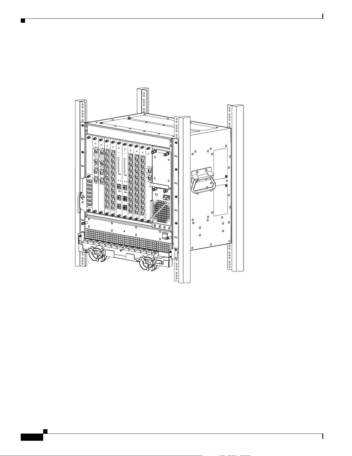
Cisco ONS 15530 Hardware Features
for system control. All optical connections are located on the front of the shelf. The Cisco ONS 15530
supports up to 60 ESCON (Enterprise Sy stem s C onnec tivity) port s on a sing le shelf and up to
160 ESCON ports i n a sta cked sh elf solu tion.
Figure 1-1 Cisco ONS 15530 Shelf
E
A
S
T
T
X
R
X
W
E
S
T
T
X
R
X
Chapter 1 Product Overview
STATUS
STATUS
STATUS
STATUS
STATUS
STATUS
STATUS
E
A
T
S
X
T
T
X
R
X
R
T
X
X
R
X
W
E
T
S
X
T
T
X
R
X
R
X
T
T
X
X
T
X
R
X
R
X
R
X
RESET
T
0
X
T
0
R
X
ACTIVE
X
R
X
T
1
X
T
R
1
X
X
R
COMPACT
X
FLASH
T
X
2
T
R
X
2
X
R
X
T
X
3
T
R
X
3
X
R
X
A
MAJOR
L
T
A
X
4
T
R
R
X
X
M
4
R
S
X
CUTOFF
T
X
T
5
R
X
X
5
R
X
CON
T
X
T
R
X
6
X
R
6
X
100MBPS
LINK
T
X
T
R
X
7
X
R
7
X
CON
T
X
T
R
X
X
8
R
X
8
T
X
T
R
AUX
X
X
9
R
X
15530-LCMB-0200
9
15530-LCMB-0200
STATUS
STATUS
0
T
X
R
X
1
T
X
R
X
2
T
X
R
X
3
T
X
R
X
4
T
X
R
X
T
5
X
R
X
T
X
6
R
X
T
X
7
R
X
T
X
8
R
X
T
X
R
9
X
15530-LCMB-0200
0
T
X
R
X
1
T
X
R
X
2
T
X
R
X
3
T
X
R
X
4
T
X
R
X
T
5
X
R
X
T
X
6
R
X
T
X
7
R
X
T
X
8
R
X
T
X
9
R
X
15530-LCMB-0200
0
1
E
A
S
T
2
T
X
R
X
W
E
3
S
T
4
5
6
7
8
9
15530-LCMB-0200
STATUS
T
X
R
X
T
X
R
X
FASTENERS MUST BE
FULLY ENGAGED PRIOR TO
OPERATING THE POWER SUPPLY
FAIL
GOOD
100-240V
8.0-3.5A
50-60HZ
RESET
ACTIVE
T
X
R
X
COMPACT
T
FLASH
X
R
X
T
X
R
X
T
X
CIRTICAL
A
R
MINOR
CIRTICAL
MAJOR
X
L
A
R
M
CUTOFF
S
T
X
R
HIST
X
CUTOFF
CLR
HIST
CLR
T
X
R
X
T
X
FDX
LINK
R
100MBPS
FDX
X
T
X
CON
R
X
T
X
R
X
AUX
T
X
R
15530-CPU
X
15530-CPU
Component Summary
The Cisco ONS 1 5530 suppo rts the fo llowing hot-swappabl e modular ha rdware co mponents:
• 10-port ESCON mu ltip lexing l ine car ds, 10 -G bp s ITU tr unk car ds, a nd 10-G E (Gig abit Ethe rn et)
uplink cards.
• Single-mode and multimode transpon der lin e cards
• OADM (optical add/drop multiplexer) modules
• Carrier motherboard s
• OSC (optical supe rviso ry cha nnel ) mod ul es
• PB-OE (per-band optical eq ualize r) module s
Cisco ONS 15530 Configuration Guide and Command Reference
1-2
79137
78-14227-01, Cisco IOS Release 12.1(10)EV2
Page 27

Chapter 1 Product Overview
• WB-VOA (wide-band variable optical attenuator) modules
• CPU switch modules
Figure 1-2 Cisco ONS 15530 Shelf Layout
OADMOADM
Line card
Line card
Exhaust Plenum
Line card
Line card
CPU switch
CPU switch
Line card
Line card
Line card
Line card
Cisco ONS 15530 Hardware Features
Power supply 0
Power supply 1
Fan Tray
77815
ESCON Multiplexing Line Cards, 10-Gbps ITU Trunk Cards, and 10-GE Uplink Cards
The ESCON multiplexing line card aggre gates up to 10 client data streams into a single 2.5-Gbps signal.
The card sends signal through the switch fabric to a 10-Gbps ITU trunk card or a 10-GE uplink card. The
trunk card converts up to four aggregated signals to an ITU-compliant wavelength, or channel. The
Cisco ONS 1553 0 s uppo rts two typ es of 10 -Gbps IT U tru nk car ds:
• Splitter—Sends the channels to two OADM modules.
• Nonsplitter—Sends the channel to only one OADM module.
The 10-Gbps ITU trunk ca rd has an transmit (laser) power in th e range o f 1 to 5 dBm and a receive
detector sensitivity range of –22 to –8dBm.
The 10-GE uplin k c ard c onverts up to f our ag gregat ed si gn als t o a 1 0 Gigabit Ethernet 1 310 -nm signa l
that can be transmitted to another shelf, such as the Cisco ONS 15540 ESPx and the
Cisco ONS 1554 0 E SP. The transm it power for the 10-GE uplink card is –8. 2 to 0.5 dBm and the
receive detector ran ge i s –14.4 to 0.5 dBm.
For more informat ion on p ower budget pl an ning , refe r t o t he Cisco O NS 15530 Plan ning and De sign
Guide. For power budget specifications for individual compo nent s, refer t o the Cisco O NS 15 530
Ha rd w are In s t al l a tion G ui d e .
78-14227-01, Cisco IOS Release 12.1(10)EV2
Cisco ONS 15530 Configuration Guide and Command Reference
1-3
Page 28

Cisco ONS 15530 Hardware Features
Transponder Line Cards
The protocol-tra nsp aren t a nd bit-r ate tra nsp ar ent tra nsp onder li ne c ar d co nverts a singl e cl ie nt si gn al
into an ITU wavelength, or channel.The Cisco ONS 15530 shelf holds up to four transponder line cards,
one for each wavelength su ppo rted by th e OADM modul es.
The Cisco ONS 15530 supports fou r ty pe s of si n gle clie nt i nte rface tran spon der l ine ca rds :
• SM (single-mode) nonsp litter
• SM splitter
• MM (multimode) nonsplitter
• MM splitter
Both types of SM transponder line cards accept SM client signals on the 1310-nm wavelength through
an SC connector and support client signal clock rates ranging from 16 Mbps to 2.5 Gbps. Both types of
MM transponder lin e cards acce pt SM and MM client signals on the 13 10-nm wavelength through an
SC connector and su ppor t c lient signa l c lock r ates r a nging from 16 Mbps to 622 Mbps.
The transponder line cards are hot pluggable, permitting in-service upgrad es and replacement.
All client signals on the transponders are supported in 3R (reshape, retime, retransmit) mode, regardless
of protocol encap sulat ion type . Th e fol lowing pr otoc ol e nca psula tio n ty pes a re su ppo rte d in 3R mo de
plus protocol monitoring:
• ESCON (200 Mbps) SM and MM
Chapter 1 Product Overview
• Fibre Channel (1 Gb ps) SM
• FICON (Fiber Connec tion) ( 800 M bps) SM
• Gigabit Ethernet (100 0 Mb ps) SM
• SDH (Synchronous Di gital Hie rarc hy) ST M- 1 SM an d MM
• SDH STM-4 SM and MM
• SDH STM-16 SM
• SONET OC-3 SM and MM
• SONET OC-12 SM and MM
• SONET OC-48 SM
• ISC (InterSystem Channel) links compatibility mode
The following protocol enc a psulat ion type s are supp orted in 3R mode wi thou t pr otoc ol m on ito ring:
• Fast Ethern et SM
• FDDI SM
• Fibre Channel (2 Gb ps) SM
• ISC peer mode SM
• Sysplex CLO (control li nk osc illa tor) MM ( 8 M bps)
• Sysplex ETR (external timer reference) MM (8 Mbps)
The client interfaces also support the OFC (open fiber control) safety protocol for Fibre Channel, ISC
compatibility mode, and FICON. Client-side interfaces are protocol transparent and can accept signals
at specific rates between 16 Mbps and 2.5 Gbps.
1-4
Cisco ONS 15530 Configuration Guide and Command Reference
78-14227-01, Cisco IOS Release 12.1(10)EV2
Page 29

Chapter 1 Product Overview
On the trunk side, the transponder line card has an output (laser) power in the range of 5 to 10 dBm and
a receive detector sensitivity r ange of –22 to –8 dBm. For more information on power budget planning,
refer to the Cisco ONS 15 530 P lannin g a nd Design Gui de. For power budget sp ecificat ions for
individual components , refer t o the Cisc o ONS 15 530 H ardware Installation Guide.
OADM Modules
The Cisco ONS 15530 supports one OADM modul e in a n u nprot ecte d con figurat ion or two OADM
modules for a protecte d configurat ion. Each OADM modul e can mu ltiplex and dem ultip lex a band of
4 channels. Cha nnels not filtered by the OADM module are passe d on to the next OADM module. In a
protected configurat ion, bo th OADM mo dule s su pport the same ba nd of c hanne ls t o provide faul t
tolerance.
Carrier Motherboards
The carrier motherboard installs into a single shelf slot and accepts two half-size modules. The carrier
motherboard suppo rts t he OSC m odule s and the VOA modules.
Cisco ONS 15530 Hardware Features
OSC Modules
VOA Modules
PB-OE Modules
The OSC cards sup por t a n o pti onal ou t-of -band m anag em ent cha nnel f or co mm unic ati ng be tw een
systems on the network. Using a 33rd wavelength (channel 0), the OSC allows control and management
traffic to be c ar ried with out re quir ing a sep arate Ethernet connection to ea ch node in the network. Up to
two OSC modules can be installe d in the c arrier mo ther board, one card for the west di rectio n and one
for the east d ire cti on.
The OSC always terminates on a ne ighboring node. By contrast, data chan nels may or may not be
terminated on a g iven node , de pen di ng on whe the r the ch an ne ls on t he OADM m odu les are t reat ed as
either express (pass-through) or add/drop channels.
The Cisco ONS 15530 supports VOA (variable optical a tten ua tor) m odule s th at work wit h E DFAs
(erbium-doped fibre a tt enua tors) to expan d DWDM op tica l ne twork s over gr eat er d ista nce s. The VOA
modules include PB-OE (per-ban d optical equal izer) modules and WB-VO A (wide- band vari able optical
attenuator) mod ul es. T hes e m odul es a r e instal le d in t he c arri er mo th erboa rd .
The PB-OE modules select an d atte nuate one or t wo specific 4-channe l bands. T he Cisco ONS 15530
supports eight single band PBOE modul es for bands A thr ough H and four dual band PB-OE modules
for bands AB, CD, EF, and GH.
78-14227-01, Cisco IOS Release 12.1(10)EV2
Cisco ONS 15530 Configuration Guide and Command Reference
1-5
Page 30

Cisco ONS 15530 Hardware Features
WB-VOA Modules
The WB-VOA modules accept and attenuate an ITU signal re ga rdless o f the chan nels in the sig nal. This
includes signals with a single c hannel , a ba nd of c hannels, or multiple bands of channels. T he re ar e tw o
types of WB-VOA modules: single and dual. The single WB-VOA module attenuates only one signal
and the dual WB-VOA module attenuates up to two signals.
CPU Switch Modules
The Cisco ONS 15530 includes on e CPU sw it ch m odule wi th a switch fabr ic. T he re m ay be two CPU
switch modules in a Cisco ONS 15530 shelf to provide a higher level of system availability. One of the
CPU switch modules is the active one (sometimes called primary or master) and the other is the standby
(sometimes ca lled secon dary , backup, or sla ve). The st andby CPU switch module is presen t for incr eased
reliability so that it can take over in case the active CPU switch module fails.
Each CPU switch mo dule h as a numbe r of sub syst ems, inc ludi ng a p roce ssor, a switch fa bric , a clo ck
subsystem, an Ethernet switch for co mmunic ation between pr ocesso rs and with th e LRC (lin e card
redundancy controller ) on t he OADM mod ule s a nd l ine c ards, and an SRC ( switc hcar d r edund an cy
controller). The active processor controls the system. All LRCs in the system use the system clock and
synchronization sig nals from the a ctive CPU switch mod ule . Int erfac es on t he CPU swit ch mo dule s
permit access by 10/100 Ethern et, cons ole ter minal , or modem co nnecti ons.
Chapter 1 Product Overview
Switch Fabric
The key features of the C isco ONS 15530 CPU switc h mod ul e ar e :
• 32 by 32 port non-bl ocki ng c rossp oint s wit ch fa bric wit h up to 3 .125 Gbps per port
• RM7000 64-bit RISC processor with internal cache
• Galileo GT96100 support chip
• Flash SIMM in a socket for up to 32 MB with a default of 16 MB
• Bootflash PROM for up to 5 12KB
• NVRAM for up to 512KB with tim e of day clock
• Console and auxiliar y serial port wi th RS-2 32C interface
• 10/100 MB NME (network management Ethernet) port
• CompactFlash card slot
• System clocking source
• Support for two CPU swit ch m odu les
• Operates from 12 V DC from t he backpl ane wit h on-card ge neratio n of 5, 3.3, 2.5 an d 1.8 V DC
• Environmental and system m onit or ing an d con t rol
• 9-port Fast Ethernet Switc h f or c omm un icat ion to li ne c ards
• SRC (switch redundancy control ler) for communi cating w ith line cards
1-6
The switch fabric, which is integrated onto the CP U switch modul e, is a 36 by 37 crosspoin t,
nonblocking switch wi th o nly 32 by 32 ports used. E ach po rt c arri es 3 .1 25 Gbps.
Cisco ONS 15530 Configuration Guide and Command Reference
78-14227-01, Cisco IOS Release 12.1(10)EV2
Page 31

Chapter 1 Product Overview
The switch fabric has a b uilt-in protec tion switch th at of fers less th an 10 ms switching time as a standard
feature. This allows uniform performance over a wide wavelength range. The built-in optical power
output measuremen t system has a w ide dyn am ic range of –20 dBm to 20 dBm. In addition it offers fast
connection setups coupled with lower level adjustment to enable fast network configuration changes.
Cisco ONS 15530 Software Features
The Cisco ONS 15530 offers the following soft ware f unc tiona li ty:
• Cisco IOS software on the CPU switch module.
• Autoconfiguration at startup .
• Autodiscovery of network neigh bors.
• Online diagnostics.
• CPU switch module redunda ncy provided by arbi tra tion of pr oc esso r status and switch over in case
of failure without loss of connections.
• Autosynchronizatio n of startup an d runni ng configurati ons betwee n redun dant CPU switch
modules.
Cisco ONS 15530 Software Features
• Support for in-service software upg rades.
• Support for per-channel APS (Automatic Protecti on Switching ) in point-to-poi nt, ring, and me sh
topologies using redundant subsystems that monitor link integrity and signal quality.
• Unidirectional and bidirectional 1+1 path switching.
• System configuration and mana gement thr ough the CL I (comman d-line in terface) , accessible
through an Ethe rn et con ne cti on or t he co nsol e t erm in al.
• Optical power monitoring on the signa l fro m the trun k, d igi tal mo nit oring on bo th cl ie nt an d trun k
interfaces, and per-channel in-servi ce and out- of-servi ce loopb ack (cli ent and trunk sides).
• Optional out-of-band m anag ement of ot h er Cisc o ONS 15530 systems on t he ne twork t hrou gh the
OSC (optical supe rviso ry cha nnel ).
• In-band management of other Ci sco O NS 15530 systems using the in-band message channe l.
• Support for network management systems that use SNMP. Its capabilities include configuration
management, fault is olati on , to polo gy d iscovery, and path trace.
Network Management Systems
The Cisco ONS 1 5530 is sup ported by the following networ k manageme nt system s:
• CiscoView
• CTM (Cisco Transport Manager)
For Embedded CiscoView configuration information, see the “Install ing and Configu ring Embedde d
CiscoView” section on p age 9-23.
The Cisco ONS 1 5530 is sup ported by CTM (Cisc o Transport Manager) versi on 3.1.
For more informatio n on th e netwo rk man ag emen t syst ems t hat sup port the C is co ONS 15530, refer to
the Network Management for the Cisco ONS 15530 document.
78-14227-01, Cisco IOS Release 12.1(10)EV2
Cisco ONS 15530 Configuration Guide and Command Reference
1-7
Page 32

Cisco ONS 15530 Software Features
Optical Supervisory Channel
The Cisco ONS 1 5530 s upports an optiona l out-of-ba nd manage ment ch annel fo r commu nicating
between systems on the network. Using a 33rd wavelength (channel 0), the OSC allows control and
management traffic to be carried without a separate Ethernet connection to each Cisco ONS 15530 in the
network. The OSC always terminates on a neighboring node. By contrast, data channels may or may not
be terminated on a given node, depending on whether the channels on the OADM modules are treated as
either express (pass-through) or add/drop channels.
The OSC carries the following types of information:
• CDP (Cisco Discovery Protocol) pac kets—Used to discover neighborin g devices
• IP packets—Use d for SN MP a nd Telnet sessions between nod es
• OSCP (OSC Protocol) packet s—Used to det ermi n e w heth er the OS C link is up us ing a Hell o
protocol
• APS protocol packets—Used for cont ro llin g sig nal pa th sw itc hing
Note When the OSC is not present, Cisco ONS 15530 systems can be managed individually by separate
Ethernet connec tions.
Chapter 1 Product Overview
The OSC is supported by separate modules and motherboards. The OSC is a full duplex channel that can
use a single ring for transmit and receive.
For more information on th e OSC and ma nagi ng Cisco ONS 15530 net works , see Chapter 9,
“Monitoring Your Network Topology.”
In-Band Message Channel
The in-band messag e chann el e stabli shes a met hod for pr oviding OAM&P (opera tions, admi nistr ati on,
management, and provision in g) func ti ons in Et her net pa cket -base d opti cal net works withou t a SONE T
layer or SDH layer. In addition, the in-band message channel enab les statistical multiple xing of multiple
logical lower-speed signals, such as ESCON signals, within a single optical data channel. The in-band
message channel te rm inat es wit h the da ta chan ne l, not a t e ach no de a s d oe s the OSC , th us providi ng
management on a per wavelength basis.
Online Diagnostics
The Cisco ONS 15530 provides the foll owing types of o nline dia gno stic tests:
• Background tests checking system component status and access
• OIR (online insertion and re moval) tests for motherboar ds, cards, and standby process ors
1-8
Cisco ONS 15530 Configuration Guide and Command Reference
78-14227-01, Cisco IOS Release 12.1(10)EV2
Page 33

Chapter 1 Product Overview
Network Topologies
The Cisco ONS 1 5530 suppo rts the fo llowing types of topol ogies:
• Point-to-point
• Hubbed ring
• Meshed ring
For more information on network topologies, refer to the Introduction to DWDM Technology publication
and the Cisc o ONS 1 5540 Plann in g and D esign G uid e.
Standards Compliance
For informat ion o n stan dard s co mpli ance fo r t he Cis co ONS 15530, refer to the Regulatory Compliance
and Safety Information for the Cisco ONS 15500 Series publication.
Network Topologies
78-14227-01, Cisco IOS Release 12.1(10)EV2
Cisco ONS 15530 Configuration Guide and Command Reference
1-9
Page 34

Standards Compliance
Chapter 1 Product Overview
1-10
Cisco ONS 15530 Configuration Guide and Command Reference
78-14227-01, Cisco IOS Release 12.1(10)EV2
Page 35

Before You Begin
This chapter provides basic information about the Cisco ONS 15530. This chapter includes the
following topics:
• About the CLI, p age 2-1
• About Cisco IOS Command Modes, page 2-1
• Interface Naming Co nventions, page 2 -4
• Configuration Overview, page 2-7
About the CLI
You can configure the Cisco ONS 15530 from the CLI (comma nd-line in terfa ce) that run s on the syst em
console or terminal, or by using remo te acc ess.
CHAPTER
2
To use the CLI, y our te rmin al mus t be c on necte d to th e C isco ONS 15530 thr ough the cons ole port o r
one of the TTY lines. By default, the terminal is configured to a basic configuration, which should work
for most terminal sessions.
About Cisco IOS Command Modes
The Cisco IOS user interface is divided into many different modes. The commands available to you
depend on which mode you are curre ntly in. To get a list of the commands available in a given mode,
type a question mark (?) at the system pr ompt.
When you start a session on the system, you begin in user mode, also called EXEC mode. Only a limited
subset of the comman ds are available in EXEC mode. To have access to all commands, you must enter
privileged EXEC mode. Normally, you must type in a password to access privileged EXEC mode. From
privileged mode, you can type in any EXEC command or access global configuration mode. Most of the
EXEC commands are one-time commands, such as show commands, which show the current
configuration status, and clear commands, w hich cle ar coun ters or i nterf aces. T he EXEC co mmands are
not saved across system reboots or across processor switchovers.
You can mon itor an d control the stan dby processor wit h command s ente red on the active processor. A
subset of EXEC a nd pr ivileged EX EC c om mands a re available throu gh th e st andby pr oc es sor co nsol e.
Note You can easily determine if you are accessing the active or the standby processor: The standby
processor has “sby-” prefixed to the command pro mpt.
78-14227-01, Cisco IOS Release 12.1(10)EV2
Cisco ONS 15530 Configuration Guide and Command Reference
2-1
Page 36

Chapter 2 Before You Begin
About Cisco IOS Command Modes
The configuration mode s al low you to make c hange s to the runni ng co nfigurati on . If yo u lat er save the
configuration, these commands are stored across system reboots. You must start at global configuration
mode. From global configurat ion mode , you can ent er inter face configur ation mode , subinte rface
configuration mode, an d a variety submod es .
ROM (Read-only memory) monitor mode is a separate mode used when the system cannot boot properly.
For example, your system or access server might enter ROM monitor mode if it does not find a valid
system image when it is booting, or if its configuration file is corrupted at startup.
Table 2-1 lists and describes the most commonly used modes, how to enter the modes, and the resulting
system prompts. The sy stem p rompt helps yo u id ent if y whi ch mod e yo u a re in a nd, t h eref ore , w hic h
commands are available to you .
Table 2-1 Frequently Used IOS Command Modes
Mode Description of Use How to Access Prompt
User EXEC To connect to remote devices,
Log in.
Switch>
change terminal settings on a
temporary basis, pe rfor m basic
tests, and display system information.
Privileged EXEC (Enable) T o set operating parameters. The
privile ged com mand set i ncludes
the comman ds i n use r E XEC
From the user E X EC mode ,
enter the enable command and
the enable pas sword.
Switch#
mode, as well as the configure
command. Use this command to
access the other command
modes.
Global configurat ion To configure features that affect
the system as a w hole.
From the privileged EXEC
mode, enter th e configure
Switch(config)#
terminal comman d.
Interface configuration To enable features for a particu-
lar interface. Interface
commands en ab le or mo dify t h e
operation of a port .
From global configurati on
mode, enter th e interface type
location command.
For example, enter
Switch(config-if)#
interface fas tet hernet 0
Line configuratio n To configure the co nsole po rt o r
VTY line from the directly
connected co nsole o r th e virt ual
terminal used with Telnet.
From global configurati on
mode, enter th e line console 0
command to configure th e
console port, or t he line vty
Switch(config-line)#
line-number command to
configure a VTY lin e.
Redundancy configuration To configure system redundancy. From global configuration
Switch(config-red)#
mode, enter th e redundancy
command.
APS1 configuration To configure APS redundan cy
features.
From redundancy configuration
mode, enter th e asso ci at e
Switch(config-aps)#
group command.
2-2
Cisco ONS 15530 Configuration Guide and Command Reference
78-14227-01, Cisco IOS Release 12.1(10)EV2
Page 37

Chapter 2 Before You Begin
About Cisco IOS Command Modes
Table 2-1 Frequently Used IOS Command Modes (continued)
Mode Description of Use How to Access Prompt
Threshold list configurati on To configure alarm thr eshold list
attributes and thresholds.
From the global configura tion
mode, enter the threshold-list
Switch(config-t-list)#
command.
Threshold configurat ion To configure alarm thre shold
attributes.
From threshold list
configuration mode, enter t he
Switch(config-threshold)#
threshold command.
1. Automatic Protection Switching
The Cisco IOS command interprete r, called the EXEC, interprets and executes t he comman ds you en ter.
You can abbreviate commands and keywords by entering just enough characters to make the command
unique from oth er c omm ands. For exa mple , you c an a bb reviate the show command to sh and the
configure terminal command to config t.
When you type exit, the CLI backs out one comm and mode level. In general, typing exit returns you to
global configuration mode. To exit configuration mode completely and return to privileged EXEC mode,
press Ctrl-Z or end.
Listing Cisco IOS Commands and Syntax
In any command m ode, you c an g et a list of available com ma nd s by e nter ing a qu esti on ma rk ( ?).
Switch> ?
To obtain a li st o f co mmand s tha t b egin w i th a p ar t icul a r ch arac t er s e qu en ce, t ype i n th o se ch ar act e rs
followed immedi ately b y th e question mark (?). Do not inc lude a space. T his f orm of hel p is calle d w ord
help, because it lists the words for you.
Switch# c?
calendar cd clear clock configure
connect copy
T o list keywords or arguments, enter a question mark in place of a keyword or argument. Include a space
before the ques tion mar k. Thi s f orm o f he lp is ca ll ed c omm and synt ax he lp, beca use i t re mind s yo u
which keywords or arguments are applicable based on the command, keywords, and arguments you have
already entered.
Switch# configure ?
memory Configure from NV memory
network Configure from a TFTP network host
overwrite-network Overwrite NV memory from TFTP network host
terminal Configure from the terminal
<cr>
To redisplay a command you previously entered, press the Up-arrow key. You can continue to press the
Up-arrow key to see more previousl y issu ed com ma nds.
Tip s If you are having trouble entering a command, check the system prompt and enter the question mark
(?) for a list o f available com ma nds. You might be in the wr ong com ma nd mo de or us ing inco rr ec t
syntax.
78-14227-01, Cisco IOS Release 12.1(10)EV2
Cisco ONS 15530 Configuration Guide and Command Reference
2-3
Page 38

Interface Naming Conventions
You can press Ctrl-Z or end in any mode to immedia tely re turn to pr ivileged EXEC (enabl e) mo de,
instead of entering exit, which r etu rns you to the previous mo de.
Interface Naming Conventions
This section describes th e interfac es and the int erface naming conventions for each type of card
supported by the Cisco ONS 15530.
ESCON Multiplexing Line Card Interfaces
The ESCON multiplexing line card has two types of interfaces:
• Esconphy interfaces
• Portgroup interfa ce s
Figure 2-1 shows the interfaces for the ESCON multiplexing line card.
Chapter 2 Before You Begin
Figure 2-1 ESCON Multiplexing Line Card Interfaces
Front panel Backplane
sconphy 3/0/0
sconphy 3/0/1
sconphy 3/0/9
Esconphy Interfaces
ESCON
PHYs
Encapsulation
engine
portgroup3/0/0
79176
2-4
The esconphy interfaces are located on the front panel of the ESCON multiplexing line cards. Each
ESCON multiplexing line card has 10 esconphy interfaces. The ESCON multiplexing line card
aggregates the signals from the escon phy inter faces into a singl e 2.5-Gbps s ignal and sen ds it to the
portgroup interface on the backplane side of the card. The esconphy is an uncolored interface that carries
ESCON physical la yer signa ls . T hi s int erfac e do es not ter mina te la yer 2 or layer 3 protocol operat ions .
The naming convention for the esconphy interfaces on the ESCON multiplexing line card is as follows:
esconphy slot/subc ard/port
Cisco ONS 15530 Configuration Guide and Command Reference
78-14227-01, Cisco IOS Release 12.1(10)EV2
Page 39

Chapter 2 Before You Begin
Portgroup Interfaces
This logical interface represe nts the a ggr e g a tion of m ultip le packet streams from slow speed interfaces.
For example, this interface is used on the Cisco ONS 15530 optical switches, where the switching
granularity is only on the level of a 2.5-Gbps aggregate packet stream resulting from multiple slow speed
interfaces such as esconphy.
The portgroup interfaces ar e locate d on the ESCO N multiplexing l ine cards. The portgr oup interfac e
connects the esconphy interfaces on the front panel to the switch fabrics. A logical interface representing
the aggregation of multiple ESCON client signals.
The naming convention for the portgroup interfaces on the ESCON multiplexing line card is as follows:
portgroup slot/subcard/port
Each ESCON multiplexing line card has only one portgroup interface.
10-Gbps ITU Trunk Card Interfaces
The 10-Gbps ITU trunk card s have four types of interfaces :
Interface Naming Conventions
• Ethernetdcc interfaces
• Wavethernetphy interfaces
• Wavethernetphy subinterfaces
• Wavepatch interfaces
Figure 2-2 shows the interfaces for the sp litte r 10- Gbps IT U tr unk c ard. Figure 2-3 shows the interfaces
for the nonsplitter 10-G bps ITU tru nk card.
Figure 2-2 Splitter 10-Gbps ITU Trunk Card Interfaces
Front panel
wavepatch 4/0/0
wavepatch 4/0/1
Splitter
module
waveethernetphy 4/0
Quad
Ser/Des
Backplane
waveethernetphy 4/0.0
waveethernetphy 4/0.1
waveethernetphy 4/0.2
waveethernetphy 4/0.3
78-14227-01, Cisco IOS Release 12.1(10)EV2
ethernetdcc 4/0/0
79178
Cisco ONS 15530 Configuration Guide and Command Reference
2-5
Page 40

Interface Naming Conventions
Figure 2-3 Nonsplitter 10-Gbps ITU Trunk Card Interfaces
Chapter 2 Before You Begin
Front panel
wavepatch 4/0/0
waveethrenetphy 4/0
Quad
Ser/Des
Backplane
waveethernetphy 4/0.0
waveethernetphy 4/0.1
waveethernetphy 4/0.2
waveethernetphy 4/0.3
ethernetdcc 4/0/0
79241
Ethernetdcc Interfaces
The ethernetdcc interfaces provide the communication path for the in-band message channel OAM
messages between the 10-Gbps ITU trunk card and the CPU switch modules. The ethernetdcc interface
connects the switch fabrics to the waveethernetphy interface.
The naming convention for ethernetdcc interfaces is as follows:
ethernetdcc slot /subcard/port
Each card has one ethernetdcc interface.
Waveethernetphy Interfaces
The waveethernetphy int erfac es corr e spon d to t he l aser o n t h e 10- G bps IT U trun k card s.
The waveethernetphy interface conn ects the four waveethernetphy subi nterface s on the ba ckpla ne side
of the 10-Gbps I TU tr unk car d to t he wavepatch in terfa ce o n th e fr ont pa nel. T he waveether net phy
interface ITU signal carr ies up to four 2.5- Gbps physical layer sign als. It does not term inat e layer 2 or
layer 3 protocol opera tions.
The naming convention for the waveethernetphy interfaces is as follows:
waveethernetphy slot/subcard/port
Each 10-Gbps ITU t run k ca rd has o ne waveethernetp hy in terfa ce.
2-6
Cisco ONS 15530 Configuration Guide and Command Reference
78-14227-01, Cisco IOS Release 12.1(10)EV2
Page 41

Chapter 2 Before You Begin
Waveethernetphy Subinterfaces
The waveethernetphy subinterfaces ar e located on t he backpla ne side of the 10-Gbps IT U trunk cards .
The waveethernetphy interfac e c onn ect s the switc h fa bric to th e waveether net phy in ter face. E ach
waveethernetphy subinterface ca n ha ndle 2 .5 Gbps of dat a t raffic.
The naming convention fo r th e waveethernet phy sub i nter faces is as fol lows:
waveethernetphy slot/subcard.subinterface
Each 10-Gbps ITU trun k c ard has f our waveethernetphy subint erfac es .
Wavepatch Interfaces
The wavepatch interfaces are on the fron t panel o f the 10-G bps ITU trunk ca rd. The waveethernetphy
interfaces connect to the wavepatch interfaces on the backplane side. The mux/demux filter interfaces
connect to the wavepatch interface on the fron t panel side.
A splitter10-Gbps ITU trunk card has two wa vepatch interfaces. An nonsplitte r10-G bps ITU tru nk card
has only one wavepatch interface.
The wavepatch interface operational state reflects the operational state of the corresponding
waveethernetphy interface. If the waveethernetphy interfaces are operationally down, the corresponding
wavepatch interfaces are operati onall y down. Conversely, if the waveethernetphy interfaces are
operationally up, then the wavepatch interfaces are up. However, the administrative states of the
waveethernetphy and wavepatch interfaces are indepe nden tly trac ked.
Interface Naming Conventions
The naming convention for wavepatch interfaces is as follows:
wavepatch slot/subcard/port
10-GE Uplink Card Interfaces
The 10-GE uplink cards have four types of interfaces:
• Ethernetdcc interfaces
• Tengigethernetphy inter faces
• Tengigethernetphy subinterfaces
• Wavepatch interfaces
Figure 2-4 shows the in terfa ces for the 10 -GE u plink ca rd .
78-14227-01, Cisco IOS Release 12.1(10)EV2
Cisco ONS 15530 Configuration Guide and Command Reference
2-7
Page 42

Interface Naming Conventions
Figure 2-4 10-GE Uplink Card Interfaces
Chapter 2 Before You Begin
Front panel
wavepatch 4/0/0
tengigethernetphy 4/0
Quad
Ser/Des
Backplane
tengigethernetphy 4/0.0
tengigethernetphy 4/0.1
tengigethernetphy 4/0.2
tengigethernetphy 4/0.3
ethernetdcc 4/0/0
79179
Ethernetdcc Interfaces
The in-band message channel OAM messages for inband management are sent and received by the CPU
switch module through the ethernetdcc interfaces. The ethernetdcc interface connects to the switch
fabrics on the backpla ne si de an d the waveethernetphy int erface on t he f ron t pane l si de.
The naming convention for ethernetdcc interfaces is as follows:
ethernetdcc slot /subcard/port
Each 10-GE u plink ca rd has one et hern et dcc int e rface .
Tengigethernetphy Interfaces
The tengigethernetphy interfaces correspond to the laser on the 10-GE uplink cards. The
tengigethernetphy interface connects to the tengigethernetphy subinterface on the backplane side of
the 10-GE uplin k ca rd an d to the wa vepa tch int erfa ce on the f ront pane l si de. This is an uncol ored
inte r fa ce t h at ca r ri e s 1 0 Gi g a bi t E thern e t. This interface does not terminate layer 2 or layer 3 protocol
operations.
The naming convention for the tengigethernetphy interfaces is as follows:
tengigethernetphy slot/subcard/port
Each 10-GE u pli nk ca rd ha s one te ng iget he rnet p hy in te rface .
Tengigethernetphy Subinterfaces
2-8
The tengigeth er net phy int erface s ar e t he bac kpla ne int erfa ce s o n th e1 0-G E up l ink ca rd s. The
tengigethernetphy int erface conne cts to the switc h fabric.
Cisco ONS 15530 Configuration Guide and Command Reference
78-14227-01, Cisco IOS Release 12.1(10)EV2
Page 43

Chapter 2 Before You Begin
The naming convention for the tengige therne tphy subinte rfaces is as fo llows:
Each 10-GE upl ink ca rd has fou r teng iget h erne tphy s ubi nte rface s.
Wavepatch Interfaces
The wavepatch interfaces are on the fron t panel of the 10-G E uplink card. The t engige therne tphy
interfaces connect to the wavepatch interfaces on the backplane side. The client interfaces on other
shelves connect to the wavepatch interface on the front panel side.
The wavepatch interface operational state reflects the operational state of the corresponding
tengigethernet phy interface . If the teng igeth ernet phy inter faces are ope rationa lly down, the
corresponding wavepatch interface s are opera tional ly down. Conversely, if the tengigethernetphy
interfaces ar e op er ationally up, then t he wavepat ch inter faces are up. However, the ad m inistrativ e s tate s
of the tengigethe rnet phy a nd wavepatch int erfac es ar e i ndepe nd en tly t rac ked.
The naming convention for wavepatch interfaces is as follows:
Interface Naming Conventions
tengigethernetphy slot/subcard.subinterface
wavepatch slot/subcard/port
Transponder Line Card Interfaces
The transponder line cards have three types of interfaces:
• Transparent interfaces
• Wave interfaces
• Wavepatch interfaces
Figure 2-5 shows the interfaces for the transponder line card.
Figure 2-5 Transponder Line Card Interfaces
Front panel Backplane
transparent 4/0/0
wavepatch 4/0/0
wavepatch 4/0/1
Optical
splitter
module
wave 4/0
78-14227-01, Cisco IOS Release 12.1(10)EV2
79180
Cisco ONS 15530 Configuration Guide and Command Reference
2-9
Page 44

Interface Naming Conventions
Transparent Interfaces
The transparent interf aces a re located o n the fro nt panel of the transp onder line cards. The interfa ce does
not terminate the protoc ol, henc e the term transparent. Also, transparent applies to transparency with
regard to networking protocols. The transparent interface connects to the wave interface on the
backplane side of th e transpo nder lin e card.
The naming convention for the transparent interfaces is as follows:
transparent slot/subcard/port
Each transponder line card has one transparent interface.
Wave Interfaces
The wav e in terface correspo nds to th e las er o n the transponder line ca rd th at generates the ch an ne l. T h e
wave inter face electrically connects to the transpa rent interfa ce on the front pa nel and optic ally connec ts
to two wave patch interf aces on a splitter card, or to one wa vepatch in terface o n a nonsplitter card, on the
ITU side.
The naming convention for wave interfaces is as follows:
wave slot/subcard
Chapter 2 Before You Begin
Each transponde r li ne ca rd has one wave interfa ce.
Wavepatch Interfaces
The wavepatch interface is the interface on the front panel that connects to the filter interfaces on the
OADM mo dules. The wave interfaces on the backplan e si d e o f the transponder line cards connect to the
wavepatch interfaces.
Splitter transponder line cards have two wavepatch interfaces. Nonsplitter transponder line cards have
only one wavepatch interface.
The wavepatch interface operational state reflects the operational state of the corresponding wave
interface. If the wave interfaces are operationally down, the corresponding wavepatch interfaces are
operationally down. Conversely, if the wave interfaces are operationally up, then the wavepatch
interfaces are up. However, the administrative states of the wave and wavepatch interfaces are
independently tracked.
The naming convention for wavepatch interfaces is as follows:
wavepatch slot/subcard/port
OADM Module Interfaces
The OADM modules can have four types of interfaces:
• Filter interfaces
2-10
• Oscfilter interfaces
• Wdm interfaces
• Thru interfaces
Figure 2-6 shows the interfaces for the OADM module.
Cisco ONS 15530 Configuration Guide and Command Reference
78-14227-01, Cisco IOS Release 12.1(10)EV2
Page 45

Chapter 2 Before You Begin
Figure 2-6 OADM Module Interfaces
Interface Naming Conventions
Filter Interfaces
Front panel
oscfilter 0/0
wdm 0/0
thru 0/0
filter 0/0/0
filter 0/0/1
filter 0/0/2
filter 0/0/3
Band
splitter
Filter
Backplane
79181
The filter interface connects to a wavepatch interface on either a transponder line card or a 10-Gbps ITU
trunk card. Each filter interface corresponds to an indiv idual wavelength filter. The filter interface
connects a wavepatch interface to a wdm interface on the same OADM module.
The naming convention for filter interfaces is as follows:
Each OADM module has fo ur filte r in ter faces.
Oscfilter Interfaces
The OADM modules can support an optional OSC with an oscfilter interface. This interface connects to
the wave interface on an OSC card.
The naming convention for the OSC interface on an OADM module is as follows:
Wdm Interfaces
The wdm interface is the interface on the OADM module that receives the DWDM signal containing
wavelengths to be dropped, or transmits the DWDM signal with added wavelengths. It represent the pairs
of fibers (Tx and Rx ) o n the fr ont pan el of an OADM modul e. Th e wdm i nte rface c onnec ts ei the r to a
wdm interface on anothe r netw ork node, or to a t hru interf ace on an O ADM module on a dif feren t chassis
in the same ne twork n ode.
The naming convention for wdm interfaces is as follows:
filter slot/subcard/port
oscfilter slot/subcard
wdm slot/subcard
78-14227-01, Cisco IOS Release 12.1(10)EV2
Cisco ONS 15530 Configuration Guide and Command Reference
2-11
Page 46

Interface Naming Conventions
Thru Interfaces
The thru interface is the interface on the OADM module that sends the DWDM signal to, or receives it
from, another OADM module without altering it. It represents the pairs of fibers (Tx and Rx) on the front
panel of an OADM modu le. Th e t hru in ter face con nect s to t h e th ru int erfac e on t he OADM m odul e in
the other subslot on the same chassis, or to a wdm interface on an OADM module on another chassis in
the same network nod e.
The naming convention for thru interfaces is as follows:
thru slot/subcard
OSC Card Interfaces
The optional OSC provides out -of-ban d mana gement com munica tions am ong the Cisco ONS 15530
systems in a network. The OSC is separate from the 32 data channels. The OSC card has one interface,
the wave interface.
Wave Interfaces
Chapter 2 Before You Begin
The wave interface corresponds to the laser on the OSC card that generates the channel. The shelf can
have up to two OSCs in the OSC motherboard, one per OADM module.
The naming convention for the OSC interface on an OADM module is as follows:
wave slot/subcard
CPU Switch Module Interfaces
The CPU switch modu les have two types o f inter faces:
• NME (network ma nage m ent Ethe rn et) int erfac e s
• Auxiliary port interfaces
NME Interfaces
Each CPU switch module has a Fast Ethe rnet in terface, called an NME , for network ma nageme nt
purposes. The NME interface on the active CPU switch module is named fastethernet 0 and the NME
interface on the standby CPU switch module is named as fastethernet-sby 0.
Each NME inte rface has a uniqu e M AC address. A lso, you must co nfigur e ea c h NM E inte rfac e w ith a
unique IP address. After a processo r switchover, when the standby CPU switch modu le takes over as
active, the IP and MAC addresses of the standby CPU switch module are reinitialized to those of the
active CPU switch module.
2-12
Note Network management syst em sessions and Telnet sessions are allowed on the N ME interface on the
active CPU switch modul e (fastethernet 0) b ut not allowe d on the NME interface on the stan dby CPU
switch module (fastethernet-sby 0).
Cisco ONS 15530 Configuration Guide and Command Reference
78-14227-01, Cisco IOS Release 12.1(10)EV2
Page 47

Chapter 2 Before You Begin
Auxiliary Port Interfaces
Each CPU switch module has an auxiliary port interface. You can use this interface for modem
connections. This interface is named aux 0. The DUART provides two UART channels, both of which
connects to an RJ-45 connector on the front panel as the console and auxiliary ports. Typically, the
console port connects to a co nsole for c onfiguring, contr olling, or debugging the CPU switc h module.
WB-VOA Card Interfaces
WB-VOA (wide-band variable optical attenuator) modu les have two types of interfaces:
• Voain interfaces
• Voaout interfaces
Voain Interfaces
The voain interface is the input interface on a WB-VOA module. It accepts the signal to be attenuated.
The naming convention for the voain interfac e on a VOA card is as follows:
Interface Naming Conventions
voain slot /subcard/port
Voaout Interfaces
The voaout interface is the output interface on a WB-VOA m odule. It transmits the attenuated signal.
The naming co nvention for th e voaout in te rface o n a VOA module is a s f ollows:
voaout slot/subcard/port
PB-OE Module Interfaces
PB-OE (per-band optical equa lizer) mo dules have four types of in terfaces:
• Voafilterin inte r fa c es
• Voafilterin subi n te r f a ce s
• Voafilterout int e rfaces
• Voabypassin interfaces
• Voabypassout interfac e s
Voafilterin Interfaces
The voafilterin interface identifies the physical port on the PB-OE that accepts the incoming DWDM
signal for power equalization.
The naming convention for the voafilterin interface on a PB-OE module is as follows:
voafilterin slot/subcard/port
78-14227-01, Cisco IOS Release 12.1(10)EV2
Cisco ONS 15530 Configuration Guide and Command Reference
2-13
Page 48

Interface Naming Conventions
Voafilterin Subinterfaces
The voafilterin subinterface identifies the attenuator within the PB-OE module.
The naming convention for the voafilterin interface on a PB-OE module is as follow s:
voafilterin slot/subcard/port.subinter face
Single band PB-OE modul es have one voafilterin sub inter face. Dua l ba nd PB-O E mod ul es have two
voafilterin subinterfaces.
Voafilterout Interfaces
The voafilterout interface sends the DWDM signal to the EDFA (erbium-doped fiber amplifier) or the
next node in the ne twork t op ology.
The naming convention for the voafilterout interface on a PB-OE module is as follows:
voafilterout slot/subcard/port
Voabypassout Interfaces
Chapter 2 Before You Begin
The voabypassout interface carries that portion of the signal not attenuated by the PB-OE module. This
interface connects to another VOA module input interface (either a voain interface or a voafilterin
interface) where the signal is further attenuated.
The naming convention for the voabypassout interface on a PB-OE module is as follows:
voabypassout slot/subcard/port
Voabypassin Interfaces
The voabypassin interface carries that por tion of t he s igna l attenu at ed on ot her modu les. Thi s int erfac e
connects to another VOA module output interface (either a voaout interface or a voafilterout interface)
where the signal was attenuated.
The naming convention fo r th e voabypassin i n terfa ce o n a PB-OE m odu le is as follows:
voabypassin slot/subcard/port
2-14
Cisco ONS 15530 Configuration Guide and Command Reference
78-14227-01, Cisco IOS Release 12.1(10)EV2
Page 49

Chapter 2 Before You Begin
Configuration Overview
To configure your Cisco ONS 15530 systems and ne twork, p erfor m the f ollowing steps:
Step 1 Select line cards and modules to meet your requirements.
For detailed information about the hardware components, refer to the Cisco ONS 15530 Hardware
Installa ti o n G u id e. For detailed informa tion on syste m planning and design, refer to the Cisco ONS
15530 Planning and Design Gui de.
Step 2 Insert the cards, motherboards, and CPU switch modules into the chassis.
For detailed information on hardware configuration rules, refer to the Cisco ONS 15530 Planning and
Design Guide.
Step 3 Configure the NME ports on the active CPU switch mod ule and on the stan dby CPU switch modu le, if
present.
For detailed information on configuring the NME port, see Chapter 3, “Initial Configuration.”
Step 4 Connect the cards with optical cables. Configure the patch connections with the CLI.
For detailed information on cabling between OADM modules, refer to the Cisco ONS 15530 Plann i ng
and Design Guide. For infor matio n on configurin g cross conne ctions , see the “Configuring Cross
Connections” section on page 4 -11.
Step 5 Configure aggregation flow identi fier, the cross conn ect ions, and t he pat ch co nne ctio ns fo r al l ESCO N
multiplexing line card and 10-Gbps ITU trunk card interfaces in the shelf. Also, configure the alarm
thresholds (optional).
Configuration Overview
For detailed information on configuring these interfaces, see Chapter 4, “Configuring ESCON Signal
Aggregation.”
Step 6 Configure either the protocol encapsulation or the clock rate for the client signal for all transponder line
cards interfaces in the shelf. Also, enable protocol monitoring for supported protocols and configure the
alarms thresholds (o ptiona l).
For detailed information on transponder line card interface configuration, see Chapter 5, “Configuri ng
Transponder Line Card Interface s.”
Step 7 Configure the VOA modules (optional).
For detailed information on VOA module interface configuration, see Chapter 6, “Configuring VOA
Module Interfaces .”
Step 8 Configure APS.
For detailed information on configuring APS, see Chapter 7, “Configuring APS.”
Step 9 Configure CPU switch module redunda ncy.
For detailed information on CPU switch module redundancy, see the “About CPU Switch Module
Redundancy” section on page 3-8.
Step 10 Configure IP connectivity on the OSC or through the in-band message channel for network management.
For detailed information on config uring IP connectivity on the OSC, see the “Configuring IP on the
OSC” section on pa ge 9-9. For information on configur ing IP conne ctivity via the in-ba nd message
channel, s ee th e “Configuring IP on Ethernet dcc Inter faces for the In- Band M essage Channe l” sect ion
on page 9-12.
Step 11 Configure C DP and the net work topology.
78-14227-01, Cisco IOS Release 12.1(10)EV2
Cisco ONS 15530 Configuration Guide and Command Reference
2-15
Page 50

Configuration Overview
Chapter 2 Before You Begin
For detailed information on network monitoring, see Chapter 9, “Monit orin g Your Network To pol ogy.”
2-16
Cisco ONS 15530 Configuration Guide and Command Reference
78-14227-01, Cisco IOS Release 12.1(10)EV2
Page 51

CHAPTER
3
Initial Configuration
This chapter descri b es how to c onfigure t he C is co ONS 15530 so it c an be acc essed by othe r devices.
• About the CPU Switch Module, page 3- 1
• Starting Up the Cisc o ONS 15530, pag e 3- 2
• Using the Console Ports, NME Port s, and Auxi liary Ports, pa ge 3-2
• About Passwords, page 3-3
• Configuring IP Access on the NME Interface, page 3-3
• Configuring the Host Name, page 3-6
• About NTP, pa ge 3-6
• Configuring NTP, page 3-7
• About CPU Switch Mod ule Re dun dancy, page 3-8
• Configuring CPU Switch Mo dule Redu nda ncy, page 3-12
• About the Software Configuration Register, page 3-21
• Changing the Software Configuration Register, page 3-25
About the CPU Switch Module
The CPU switch module provides intelligence to the Cisco ONS 15530. The CPU switch module
supports SNMP (Simple Networ k Manage ment Protoc ol) and many MIBs (M anag emen t Informa tion
Bases).
The Cisco ONS 15530 uses a QE D RM700 0 R ISC pr ocesso r. It runs at 78 MH z ext erna ll y and a t 23 4
MHz internally. It has a 64-bit multiplexed address and data bus with byte parity running at 78 MHz. It
has separate inte rnal L 1 in struc ti on and dat a c ach es of 16 K B eac h a nd inte rn al L 2 co mb ined
instruction/data cac he of 256 KB.
The CPU switch modules also contains a 32 by 32 switch fabric that directs traffic from client cards to
trunk cards. The s wit ch fa bric suppo rt s 2.5 Gbps data signals w it h 2R t ranspa rency.
The CPU switch module provides a slot on the front panel that accommodat es a CompactFlash card. You
can use the CompactFlash card for system image upgrades, FPGA image upgrades, statistics gathering,
and other file system applications.
The Cisco ONS 15530 supports re dun dan t op erat ion w ith d ua l CPU s witc h mo dul es . T he C P U sw itch
modules reside in slots 5 and 6, the sixth and seventh slots from the left as you face the chassis. For more
information about redun dancy, see the “About CPU Switch Module Redundancy” sect ion o n page 3-8.
78-14227-01, Cisco IOS Release 12.1(10)EV2
Cisco ONS 15530 Configuration Guide and Command Reference
3-1
Page 52

Starting Up the Cisco ONS 15530
For more information on the CPU switch module, refer to the Cisco ONS 15530 ESP Hardware
Installa ti o n G u id e.
Starting Up the Cisco ONS 15530
Before starting up the Cisco ONS 15530, you should verify the following:
• The system is se t for th e corr ec t AC (or D C) power voltages .
Refer to the Cisco ONS 155 30 Hardware Installation Guide for corre ct power voltages.
• The cables are co nnecte d to th e syst em.
• A console terminal is connected to the system.
Refer to the C isco ONS 155 30 Hardware Installation Guide for in structions.
When you start up the Cisco ON S 15530, the CLI (command-line interface ) prompts you to enter the
initial configuration dialog. Answer no to this prompt:
Would you like to enter the initial dialog? [yes]: no
You see th e following user EXE C prompt:
Switch>
Chapter 3 Initial Configuration
You can now begin configuring the CPU switch mod ule.
Using the Console Ports, NME Ports, and Auxiliary Ports
You can co nfigure the Cisc o ON S 1553 0 from a di rect conso le conne ction to the console por t or
remotely through it s NME (networ k manag ement Etherne t) port.
• If you are usin g a dir ec t c on sole c onnec tio n, c onfigure yo ur ter mina l e mu lati on progr am f or
9600 baud, 8 data bits, no parity, and 1 stop bit.
• If you are using the NME port interface , you must assign a n IP address t o the inter face
(fastethernet 0).
For interface configuration instructions, see the “Configuring IP Access on t he N ME In ter face”
section on page 3-3.
For further details on configuring ports and lines for management access, refer to the
Cisco IOS Configuration Fundam ent als Con figuration Guide.
Modem Support
The auxiliary port of the Cisco ONS 15530 provides modem connection support. The follo wi ng settings
on the modem are required:
• Enable auto answ er mod e.
3-2
• Suppress result codes.
• Ensure auxiliary port terminal characteristics, such as speed, stop bits, and parity, match those of
the modem.
Cisco ONS 15530 Configuration Guide and Command Reference
78-14227-01, Cisco IOS Release 12.1(10)EV2
Page 53

Chapter 3 Initial Configuration
You ca n configure you r m od em by se tting the DIP sw itch es on t he m ode m i tsel f or by se ttin g th em
through terminal equipment connected to the modem. Refer to the user manual provided with your
modem for the correct configuration information.
For further detail s on con figuring po rts a nd m odems fo r mana geme nt a cce ss, re fe r t o th e Cisc o IO S
Configuration Fundamentals Configuratio n Gu ide and the Cisco IOS Dial Se rvic es Co nfiguration
Guide: Terminal Services.
About Passwords
You can configure both an enable password and an enable secret password. For maximum security, the
enable password should be different fro m the en able sec ret password.
Enable Password
The enable password is a non encr ypted password that con trols acce ss to various comman ds and
configuration modes. It con tai ns from 1 to 25 uppercas e a nd lowercase a lpha nu meri c c ha racte rs. G ive
the enable password only to users permitted to make config uration changes to the Cisco ONS 15530.
About Passwords
Enable Secret Password
The enable sec ret p assword is a s ecur e, e ncryp ted pa ssword. O n syste ms run ning Ci sco I OS, you m ust
type in the enable secr e t pa ssword b efor e you c an a cce ss glo bal configura tio n mode .You must type in
the enable secret password to access boot ROM software.
Caution If you specify an encryption-type and then enter a clear text password, you will not be able to reenter
enable mode. You cannot recover a lost password t hat h as be en enc ryp ted by any me thod.
An enable secr et passw ord co ntains from 1 to 25 uppercase and lo wercas e alphan umeric charact ers. The
first character cannot be a nu mber. Spaces are valid password char acter s. Leadi ng spaces ar e ignore d;
trailing spaces are recognized.
You will configure passwords in the next section, Configuring IP Access on the NME Interface.
Configuring IP Access on the NME Interface
The Fast Ethernet in ter face, or NM E, o n t h e act ive CPU switch m odu le, name d fastethernet 0, is the
management interface that allows multiple, simultaneous Telnet or SNMP network management
sessions.
You can remotely configure the Cisco ONS 15530 through the Fast Ethernet interf ace, b ut f irst you m ust
configure an IP address so that the active CPU switch module is reachable. You can configure the NME
interface two ways: ma nually from the CLI or b y copyi ng the conf iguration from the BOO TP server int o
NVRAM.
For information on configuring the NM E interface on the st andby CPU switc h module,
fastethernet-sby 0, see the “Bo oting fro m a TFTP Server ” sec tion on page 10-7.
78-14227-01, Cisco IOS Release 12.1(10)EV2
Cisco ONS 15530 Configuration Guide and Command Reference
3-3
Page 54

Configuring IP Access on the NME Interface
Note Before you begin to manually configure an NME interface, obtain its IP address and IP subnet mask.
Also make sure the cons ol e cabl e i s co nnec ted to th e consol e port .
To configure IP access on the NME port fastethernet 0 from the CLI, perform these steps from the
console interface :
Command Purpose
Step 1
Switch> enable
Switch#
Step 2
Step 3
Switch# show hardware Verifies the installed ha rdw are p art numbe rs and seri al
Switch# configure termina l
Switch(config)#
Step 4
Step 5
Step 6
Switch(config)# enable password password Sets the enable password. See the “About Passwor ds”
Switch(config)# enable secret password Specifies an enable secret password. Once set, the
Switch(config)# interface fastethernet 0
Switch(config-if)#
Step 7
Switch(config-if)# ip address ip-address
subnet-mask
Step 8
Step 9
Step 10
Switch(config-if)# speed {10 | 100 | auto} Specifies the transmission speed. The default is auto
Switch(config-if)# duplex {auto | full | half} Specifies the duplex mode. The default is auto
Switch(config-if)# exit
Switch(config)#
Step 11
Switch(config)# line vty line-number
Switch(config-line)#
Step 12
Step 13
Switch(config-line)# password password Specifies a password for Telnet sessions.
Switch(config-line)# end
Switch#
Step 14
Switch# copy system:running-config
nvram:startup-config
Chapter 3 Initial Configuration
Enters privileged EXEC mode.
numbers.
Enters global configura tio n mod e.
section on page 3-3.
enable secret password must be entered to gain access
to global configuration mo de.
Enters interface config uration mode on interface
fastethernet 0, th e NME port on the active CPU switch
module.
Specifies the IP address and IP subnet mask for the
management port interface.
(autonegotiation).
(autonegotiation).
Returns to global configur atio n m ode .
Enters line configurati on mode for vi rtual terminal
connections. Comm ands en tered in th is mode con trol
the operation of Telnet sessions.
Returns to privileged EXEC mode.
Saves the configuration changes to NVRAM.
3-4
The Cisco ONS 15530 NME interface should now be operating correctly.
Note If a CPU switch module switchover occurs, you can use the same IP address to access the redundant
CPU switch module after it becomes active.
Cisco ONS 15530 Configuration Guide and Command Reference
78-14227-01, Cisco IOS Release 12.1(10)EV2
Page 55

Chapter 3 Initial Configuration
Note In a multiple shelf node configuration, perform these steps on the NME interfaces on all shelves in
the node.
Displaying the NME Interface Configuration
To display the configuration of the NME interface, use the following EXEC command:
Command Purpose
show interf ace s f a st et hern et 0 Displays the NTP status.
Example
Switch# show interfaces fastethernet 0
FastEthernet0 is up, line protocol is up
Hardware is AmdFE, address is 0000.1644.28ea (bia 0000.1644.28ea)
Internet address is 172.20.54.152/24
MTU 1500 bytes, BW 10000 Kbit, DLY 1000 usec,
reliability 255/255, txload 1/255, rxload 1/255
Encapsulation ARPA, loopback not set
Keepalive set (10 sec)
Half-duplex, 10Mb/s, 100BaseTX/FX
ARP type: ARPA, ARP Timeout 04:00:00
Last input 00:00:00, output 00:00:00, output hang never
Last clearing of "show interface" counters never
Input queue: 0/75/0/0 (size/max/drops/flushes); Total output drops: 0
Queueing strategy: fifo
Output queue :0/40 (size/max)
5 minute input rate 3000 bits/sec, 6 packets/sec
5 minute output rate 1000 bits/sec, 3 packets/sec
36263 packets input, 3428728 bytes
Received 17979 broadcasts, 0 runts, 0 giants, 0 throttles
0 input errors, 0 CRC, 0 frame, 0 overrun, 0 ignored
0 watchdog
0 input packets with dribble condition detected
20363 packets output, 4279598 bytes, 0 underruns
0 output errors, 8 collisions, 0 interface resets
0 babbles, 0 late collision, 72 deferred
0 lost carrier, 0 no carrier
0 output buffer failures, 0 output buffers swapped out
Configuring IP Access on the NME Interface
Displaying the Operating Configurations
You ca n displ ay t h e co nfigur ation file w h en yo u a re in p rivileged EXE C ( en ab le) m ode.
• To see the curre nt ope rat ing co nfigurat ion, ent er t he fo llowing c om man d a t t he e na ble pr ompt :
Switch# more system:running-config
• To see the configura tion saved in N VR AM, ent er th e fo llowing com ma nd:
Switch# more nvram:startup-config
If you made changes to the configuration, but did not yet writ e t h e changes to NVRAM, the contents of
the running-config file will differ from the contents of the startup-config file.
78-14227-01, Cisco IOS Release 12.1(10)EV2
Cisco ONS 15530 Configuration Guide and Command Reference
3-5
Page 56

Configuring the Host Name
Configuring the Host Name
In addition to p assword s and a n IP addr es s, you r in itia l c onfiguration sh ould i nclu de t he h ost n am e t o
make it easier to configure and troubleshoot the Cisco ONS 15530. To configure the host name, perform
the following steps:
Command Purpose
Step 1
Step 2
Step 3
Step 4
Switch# configure termina l
Switch(config)#
Switch(config)# hostname name Specifies a system name.
name(config)# end
name#
name# copy system:running-config
nvram:startup-config
Chapter 3 Initial Configuration
Enters global configuration mod e.
Returns to privileged EXEC mode. The prompt indicates
that the host name has been set to the new name.
Saves your configuration changes to NVRAM.
Note The host name is also synchronized with the standby CPU switch module. The host name prompt on
About NTP
the standby CPU switch module appears with “sby-” as a prefix.
Example
The following example shows how to configure a n ew host na me, b eginni ng in p rivileged EXEC mod e:
Switch# configure terminal
Switch(config)# hostname ONS15530
ONS15530(config)# end
ONS15530# copy system:running-config nvram:startup-config
The NTP (Network Time Protocol) is a utility for synchronizing system clocks over the network,
providing a precise time base for networked workstations and servers. In the NTP model, a hierarchy of
primary and secondar y servers pass time keeping info rmation by way of the Inte rnet to cross- check
clocks and co rrec t err ors ari si ng fr om e quipm en t or p rop agat ion fa ilu res .
An NTP server must be accessible by the client switch. NTP runs over UDP (User Datagram Protocol),
which in turn runs over IP. NTP is documented in RFC 1305. All NTP communication uses UTC
(Coordinated Universal Time), which is the same as Greenwich Mean Time. An NTP network usually
gets its time from an authoritative time source, such as a radio clock or an atomic clock attached to a
time server. NTP distributes this time across the network. NTP is extremely efficient; no more than one
packet per minute is necessary to synchronize two machines to within a millisecond of one another.
NTP uses a stratum to describe how many NTP hops away a machine is from an authoritative time
source. A stratum 1 time ser ver has a radio or atomic clock dire ctly att ached , a stra tum 2 time ser ver
receives its time from a stratum 1 time server, and so on. A machine running NTP automatically chooses
as its time source the machine wit h the lo w est stratum number that it is co nf igured to communi cate with
through NTP. This strategy effectively builds a self-organizing tree of NTP speakers.
3-6
Cisco ONS 15530 Configuration Guide and Command Reference
78-14227-01, Cisco IOS Release 12.1(10)EV2
Page 57

Chapter 3 Initial Configuration
NTP has two ways to avoid synchroniz ing to a m achi ne whose time mi ght be a mbig uous:
• NTP never synchronizes to a machine that is not synchronized itself.
• NTP compares the time rep orte d by se v eral m achines and do es not synchro nize to a mac hine whos e
The communications between machines running NTP, known as associations, are usually statically
configured; each ma chine is gi ven the IP add ress of all mach ines with which it should f orm asso ciations.
Accurate timekeeping i s possible by exchanging NTP messages between each pair of machines with an
association.
The Cisco implementation of NTP does not support stratum 1 service; it is not possible to connect to a
radio or atomic clock. We recommend that you obtain the time service for your network from the public
NTP servers available in the IP Internet. If the network is isolated from the Internet, the Cisco NTP
implementation allo ws a machin e to be conf igured so th at it acts as though it is synchronize d using NTP,
when in fact it has determined the time using other means. Other machines then synchronize to that
machine using NTP.
A number of manufacturers inc lude NT P so ftware for their host systems, a nd a version for systems
running UNIX and its various derivatives is also publicly available. This software allows host systems
to be time-synchronized as well.
Configuring NTP
time is significantly different from the others, even if its stratum is lower.
Configuring NTP
NTP services are enabled on all interfaces by default. You can configure your Cisco ONS 15530 in either
of the following NTP associations:
• Peer association—This system either sync hron izes to th e other syst em or al lo ws th e other sy stem to
synchronize to it.
• Server association—This system synchronizes to the other system, and not the other way around.
From global configurat ion mod e, us e t he f ol lowing pro cedur e to c onfigure NTP in a ser ver associ ati on
that transmits broadcast packets and periodically updates the calendar:
Command Purpose
Step 1
Step 2
Step 3
Step 4
Switch(config)# ntp update-calendar Updates ha rdware c a len dar wit h NTP t im e.
Switch(config)# ntp server ip-address Forms a server association with another system. You can
Switch(config)# end
Switch#
Switch# copy system:running-config
nvram:startup-config
For information on other optional NTP configuration s, see the Ci sco IOS Con figuration Funda men tals
Configuration Guide.
specify multiple associations.
Returns to privileged EXEC mode.
Saves your configuration changes to NVRAM.
78-14227-01, Cisco IOS Release 12.1(10)EV2
Cisco ONS 15530 Configuration Guide and Command Reference
3-7
Page 58

About CPU Switch Module Redundancy
Displaying the NTP Configuration
To view the current NTP configurati on and status, use the following EXEC command:
Command Purpose
show ntp status Displays the NTP status.
Example
The following example shows the NTP configuration and status:
Switch# show ntp status
Clock is synchronized, stratum 4, reference is 198.92.30.32
nominal freq is 250.0000 Hz, actual freq is 249.9999 Hz, precision is 2**24
reference time is B6C04F19.41018C62 (18:21:13.253 UTC Thu Feb 27 1997)
clock offset is 7.7674 msec, root delay is 113.39 msec
root dispersion is 386.72 msec, peer dispersion is 1.57 msec
Chapter 3 Initial Configuration
About CPU Switch Module Redundancy
The Cisco ONS 15530 supports fault tolerance by allowing the standby CPU switch module to take over
if the active CPU switch module fails. This standby, or redundant, CPU switch module runs in
hot-standby state. In hot-sta ndby state, the stand by CPU switch mo dule is partially boo ted with Cisco
IOS software, but no configuration is loaded.
At the time of a switchover from the active CPU switch module, the standby CPU switch module
becomes active and loads the configuration as follows:
• If the running configuration file on the ac tive and standby CPU switch module s match, the new
active CPU switch module uses the running configuration file.
• If the running configu ration f ile on the ne w acti v e CPU switch module is missing or in v alid, t he ne w
active CPU switch module uses the startup configuration file in its NVRAM (not the NVRAM of
the former active CPU switch module).
The former active CPU switch module then reloads and becomes the standby CPU switch module.
Note If the standby CPU switch module is unavailable, the system reports a minor alarm. Use the show
facility-alarm status command to display the redundancy alarm status.
When the Cisco ONS 15530 is powered on, the two CPU switch module s arbitrate to de termine which
is the active CPU switch modul e and which is the standby CPU switch module. The follo wing rules apply
during arbitration:
• A newly inserted CPU switch module a lways come s up as the st andby CPU sw itch mo dule , except
in cases where the newly inserted card is the only one present.
3-8
• If one of the CPU switch modules cannot boot its software image, the redundant CPU switch module
boots as the ac tive CPU switch m odule , a llowing yo u to cor re ct th e situa tion m anua lly.
• The primary route pro cessor at the time the system is powered off continue s as the prim ary when
the system is powered on.
• If none of the above conditions is true, the CPU switch module in slot 6 becomes the active CPU
switch module.
Cisco ONS 15530 Configuration Guide and Command Reference
78-14227-01, Cisco IOS Release 12.1(10)EV2
Page 59

Chapter 3 Initial Configuration
During normal ope ra tion, the active CPU swit ch mo dule b oots co mple tely. The standby CPU switc h
module partial ly b oots, stop pi ng shor t o f p ars ing the configur ation . From t h is po int, th e active and
standby CPU switch modu les co mmuni cate p eriod ical ly to sy nc hroni ze any syste m c onfigurat ion
changes.
Table 3-1 descri bes the five CPU switch module hardware states.
Table 3-1 CPU Switch Module Hardware States
State Description
Active Processor card is currently providing clock signals and control for all system
Standby Processor card is partially booted in hot-standby state waiting to switch over
Nonparticipant Processor card is in ROMMON mode, or is in the process of booting, or has
Not plugged in Processor car d slot is empty.
Error Processor card is present but either the interprocess arbitration interface is
About CPU Switch Module Redundancy
cards. The active CPU swit ch m odule r espond s to t he c onfigured
management IP addr es s.
when the activ e CPU switch module fails, when it is rebooted or remov ed, or
when a manual switchover is requested.
not yet reac hed the hot-s tandby s tate. Manual switchov ers are r ejected unle ss
the force option is used .
not functioning or the CPU switch module is no t fully seat ed in the ch assis
slot.
78-14227-01, Cisco IOS Release 12.1(10)EV2
Cisco ONS 15530 Configuration Guide and Command Reference
3-9
Page 60

About CPU Switch Module Redundancy
Figure 3-1 shows the valid hardware transition states for a system with redundant CPU switch modules.
Figure 3-1 CPU Switch Module State Transition Diagram
Chapter 3 Initial Configuration
Nonparticipant
Active Standby
Not plugged in
(processor card
removed)
Error
58645
In response to redundancy events, such as switchovers and reboots of the active CPU switch module, the
software transitions throu gh a series of soft ware redunda ncy states. Table 3-2 lists some of the
significant software states.
Table 3-2 CPU Switch Module Software States
State Description
Disabled The standby CPU switch module is not yet running the system image or is in
maintenance mode .
Standby cold The standby CPU switch module is running the system image but has not
begun to synchroni ze data fro m the ac tive CPU switch m odu le.
Standby hot The standby CPU switch module has fully synchronized the configuration and
other data from the active CPU switch module. It will remain in the
hot-standby state until a switchover occurs.
Active The CPU switch module is in th e act ive hardware state and has completed all
switchover or initia l bootup proce ssing. It is fully rea dy to contro l the syste m.
3-10
Cisco ONS 15530 Configuration Guide and Command Reference
78-14227-01, Cisco IOS Release 12.1(10)EV2
Page 61

Chapter 3 Initial Configuration
Redundant Operation Requirements
For fully redundant operatio n, the following requi remen ts must be met:
• Two CPU switch modules are required.
• The CPU switch modules must have identical hardware configurations. This includes variables such
as DRAM size, a nd so on.
• Both CPU switch modules must have the same functional image.
• Both CPU switch modules must be running compatible system images. System images are
compatible across one major release.
• Both the running and startup configurations are automatically synchronized between the CPU
switch modules.
• Both CPU switch modules must be set to autoboot (a default setting).
If these require me nts are m et, the Ci sco ONS 15530 runs i n r ed und ant mod e by de fault. If they ar e n ot
met, the system is conditiona lly redunda nt.
Note For detailed in formation on u pdating system images, see t he “Updating System Images on Redundant
Processors” section on page 1 0-14.
About CPU Switch Module Redundancy
Conditions Causing a Switchover from the Active CPU Switch Module
The following cond itions can cause a switchov er from the ac tiv e CPU switch module to the standby CPU
switch module:
• The active CPU switch module is removed or swapped. When the CPU switch module functioning
as the active CPU switch mo dule is r emoved, the sta ndby C PU sw itch mo dule takes over. The
Cisco ONS 1553 0 is non redun da nt u ntil a se cond CPU swit ch m odu le is inse rte d.
• The active CPU switch module is rebooted. When a CPU switch module functioning as the active
CPU switch module is rebooted, it relinquishes its acti ve role if the stan dby CPU switch module has
reached the hot-standby state.
• The active CPU switch module f ail s . Th e standby CPU switc h m odu le takes over as the active CPU
switch module, using the last synchron ized run ning configuration file (or the last saved startup
configuration file if the running configurat ion file synchroni zation was disabled or failed).
• A switchover is manually forced with the redundancy switch-activity command.
78-14227-01, Cisco IOS Release 12.1(10)EV2
Cisco ONS 15530 Configuration Guide and Command Reference
3-11
Page 62

Configuring CPU Switch Module Redundancy
Configuring CPU Switch Module Redundancy
This section desc ribes how to c onfigure CPU s witc h m odul e re dun dancy f or you r Cisco ONS 15530.
Note The initial defaul t c onfigurati on w il l sup por t CPU s wit ch m od ule redun da ncy and dat abase
synchronization with no manua l configurati on required.
Forcing a Switchover from Privileged EXEC Mode
You can manually force the standby CPU switch module to take over as the active CPU switch module
from privileged EXEC mode. To force a switchover from privileged EXEC mode, en ter the fo llowing
command on the ac tive CPU switc h modul e CLI:
Command Purpose
redundancy switch-activity [force] Causes a CPU switch module switchover. If the
standby CPU switch module has not reached the
hot-standby software sta te, us e the force opti on.
Chapter 3 Initial Configuration
As long as you have not c hang ed the d efault configurat ion r egister setti ng from a utobo ot, the sta ndby
CPU switch module (formerly the active CPU switch module) automatically boots until it reaches the
hot-standby state.
Note Data transmission through the system is not affected by a CPU switch module switchover.
Example
The following example shows how to manually cause a CPU switch module switchover from privileged
EXEC mode:
Switch# redundancy switch-activity
This will reload the active unit and force a switch of activity [confirm] y
Preparing to switch activity
00:12:05: %SYS-5-RELOAD: Reload requested
<Information deleted>
3-12
Cisco ONS 15530 Configuration Guide and Command Reference
78-14227-01, Cisco IOS Release 12.1(10)EV2
Page 63

Chapter 3 Initial Configuration
Forcing a Switchover from ROM Monitor Mode
You can manually force the standby CPU switch module to take over as the active CPU switch module
ROM monito r mode. To force a switchov er fr om ROM monitor mode, enter the following comm ands on
the active CPU switch module CLI:
Command Purpose
switchover Causes a CPU switch module reset and switchover.
The CPU switch module stays in R OM monitor mode .
Note Using the reset command in ROM monitor mode on the active processor CLI under nor mal
conditions does not cause a switchover.
Example
The following example shows how to manually cause a CPU switch module switchover from ROM
monitor mode:
<Information deleted>
Configuring CPU Switch Module Redundancy
This CPU is ACTIVE (sev=0), peer CPU is NON-PARTICIPANT (sev=2)
MANHATTAN_OPTICAL platform with 131072 Kbytes of main memory
rommon 1 > switchover
System Bootstrap, Version 12.1(20010726:234219) [ffrazer-lh4 102], DEVELOPMENT S
OFTWARE
Copyright (c) 1994-1999 by cisco Systems, Inc.
Flash size is 16777216
Reset Reason Register = RESET_REASON_SW_NMI (0x4)
Reset type 0x2
Reading monitor variables from NVRAM
Running reset I/O devices
Enabling interrupts
Initializing TLB
Initializing cache
Initializing required TLB entries
Initializing main memory
SDRAM DIMM size 67108864
Sizing NVRAM
Initializing PCMCIA controller
Initializing SRC FPGA
CPU arbitration
This CPU is NON-PARTICIPANT (sev=2), peer CPU is ACTIVE (sev=0)
MANHATTAN_OPTICAL platform with 131072 Kbytes of main memory
rommon 1 >
78-14227-01, Cisco IOS Release 12.1(10)EV2
Cisco ONS 15530 Configuration Guide and Command Reference
3-13
Page 64

Configuring CPU Switch Module Redundancy
Configuring Autoboot
If you have changed th e de fault co nfigura tion regi ster value f rom aut ob oot, y ou ca n ch an ge i t b ack by
performing the following steps, beginning in glo bal configurati on mode:
Command Purpose
Step 1
Step 2
Step 3
Step 4
Switch(config)# config-register 0x2102 Sets the configuration r egister f or a utobo ot.
Switch(config)# boot system
bootflash:filenam e
Switch(config)# end
Switch#
Switch# copy system:running-config
nvram:startup-config
1. This is the default configuration register setting. For details on using the configuration register to set boot parameters, refer
to the Cisco IOS Configuration Fundamentals Configuration Guide.
Chapter 3 Initial Configuration
1
Sets the BOOT environment variable. This variable
specifies the location and name of the system image
file to use when automatically booting the system.
Returns to privileg ed EXEC mode.
Saves the configuration to NVRAM. The new
configuration register value takes effect after the next
system reload.
Note If the standby CPU switch module remains in ROM monitor mode, you can manually boot the CPU
switch module us in g a system im ag e eit her on the boot fla sh or on a Fla sh PC Ca rd .
Example
The following example shows how to co nfigure th e Ci sco ONS 15530 to a utob oot us ing the first valid
file on the Flash PC Card in slot 0:
Switch(config)# config-register 0x2102
Switch(config)# boot system flash slot0:
Switch(config)# end
Switch# copy system:running-config nvram:startup-config
Displaying the Autoboot Configuration
To display the configuration register value, use the following EXEC command:
Command Purpose
show version Displays the configuration register value.
show bootvar Displays the configuration register value.
3-14
Cisco ONS 15530 Configuration Guide and Command Reference
78-14227-01, Cisco IOS Release 12.1(10)EV2
Page 65

Chapter 3 Initial Configuration
Example
The following example shows the contents of the configuration register:
Switch# show version
Cisco Internetwork Operating System Software
IOS (tm) ONS-15530 Software (manopt-M0-M), Experimental Version 12.1(20010221:0]
Copyright (c) 1986-2001 by cisco Systems, Inc.
Compiled Tue 20-Feb-01 18:40 by lthanvan
Image text-base: 0x60010968, data-base: 0x604D8000
ROM: System Bootstrap, Version 12.1(20010204:232442) [vsankar-alarm_fix 106], DE
BOOTFLASH: M1540-ODS Software (manopt-M0-M), Experimental Version 12.1(20001229]
M1 uptime is 1 minute
System returned to ROM by power-on
System image file is "tftp://171.69.1.129//tftpboot/lthanvan/manopt-m0-mz"
cisco (QUEENS-CPU) processor with 98304K/32768KB of memory.
R7000 CPU at 234Mhz, Implementation 39, Rev 2.1, 256KB L2, 2048KB L3 Cache
Last reset from unexpected value
2 Ethernet/IEEE 802.3 interface(s)
509K bytes of non-volatile configuration memory.
Configuring CPU Switch Module Redundancy
16384K bytes of Flash internal SIMM (Sector size 64K).
Configuration register is 0x2102
The following exam pl e s h ows the co n tent s of the b oot variab le :
Switch# show bootvar
BOOT variable = bootflash:ons15530-i-mz.1;
CONFIG_FILE variable =
BOOTLDR variable =
Configuration register is 0x2
Standby auto-sync startup config mode is on
Standby auto-sync running config mode is on
Synchronizing the Configurations
During normal opera ti on, t he sta rtu p and r unnin g c on figurati ons are syn ch ron ized by d efa ult be tw een
the two CPU switch modules. In the event of a switchover, the new active CPU switch module uses the
current running configuration. Configurations are synchronized either manually from the CLI using the
redundancy manual-sync command or automatically following configuration changes input from the
CLI or from SNMP if automatic synchronization is enabled.
Synchronizing Configurations Manually
T o immed iately synchroniz e the conf iguratio ns used by the two CPU switch modules, use the following
privileged EXEC command on the active CPU switch module:
Command Purpose
redundancy manual-sync {startup-config |
running-config | both}
78-14227-01, Cisco IOS Release 12.1(10)EV2
Immediately synchro ni zes the c onfigurati on.
Cisco ONS 15530 Configuration Guide and Command Reference
3-15
Page 66

Configuring CPU Switch Module Redundancy
Example
The following example sh ows how to manua ll y s ync hron iz e t he ru nning co nfigura tio n:
Switch# redundancy manual-sync running-config
Enabling and Disabling Automatic Synchronization
You can en able and disable aut omatic synchro nizati on of the runn ing configurat ion and the st artup
configuration between the two CPU switch modules. Automatic synchronization ensures that, when a
switchover occurs, the standby CPU switch module has the most recent configuration information.
Note By default, the Cisco ONS 15530 automatically synchronizes the running configuration and the
startup configuration betwe en the two C PU switch mo dules.
Table 3-3 lists the events that cause the automatic synchronization of the configuration files.
Table 3-3 Synchronization Events for Configuration Files
Filename When Synchronized
running-config Upon exiting from global configuration mode in the CLI, or
startup-config When a new conf iguration is copied to NVRAM on th e activ e
Chapter 3 Initial Configuration
within 5 sec onds after a n SNM P mes sage t hat ch ange s the
configuration
CPU switch module
Step 1
Step 2
Step 3
To enable or disable the system to automatically synchronize the configurations on both CPU switch
modules, perform the f ollowing st ep s on the a c tive CPU switch mo dule , begi nning in glob al
configuration mode:
Command Purpose
Switch(config)# redundancy
Enters redundancy configuration mod e.
Switch(config-red)#
Switch(config-red)# [no] auto-sync running-config Enables or disables synchronization of the
running configuration whe n it is updat ed. The
default state is enabled.
Switch(config-red)# [no] auto-sync startup-config Enables or disables synchronization of th e
startup configuration when it is updated. The
default state is enabled.
Example
The following example sh ows how to disab le au t omat ic synchr oniz ati on o f t h e run ni ng configurat ion :
Switch(config)# redundancy
Switch(config-red)# no auto-sync running-config
Switch(config-red)# end
Switch# copy system:running-config nvram:startup-config
3-16
Cisco ONS 15530 Configuration Guide and Command Reference
78-14227-01, Cisco IOS Release 12.1(10)EV2
Page 67

Chapter 3 Initial Configuration
Configuring Maintenance Mode
You can co nfigure the Cisc o ON S 15530 to enter the redundancy mainte nance mo de. Con figuration
synchronizations and sta ndby CPU switch module fault repo rting are suppressed in mai ntenance mode.
Upon exiting maintenanc e m ode and reverting t o re dund an t m ode, the sta ndby swi tch CPU switc h
module reboots to t he h ot-sta ndby sta te.
Note When the system is in maintenance mode, switchovers only occur by entering the redundancy
switch- act ivit y force command, or physically removing the active CPU switch module.
To configure maintenance mode , perform the following ste ps, beginning in global configurati on mode:
Command Purpose
Step 1
Step 2
Switch(config)# redundancy
Switch(config-red)#
Switch(config-red)# maintenance-mode Configures the system in maintenance mode.
Configuring CPU Switch Module Redundancy
Enters redundancy configuration mod e.
Example
The following example sh ows how to configure re dun da ncy maint ena nc e mo de :
Switch(config)# redundancy
Switch(config-red)# maintenance-mode
This command will place the system in SIMPLEX mode [confirm] y
Displaying the CPU Switch Module Redundancy Configuration and Status
To display the CPU swit ch mo dul e r edund an cy co nfigurati on a nd stat us , use the f ollowing privileged
EXEC commands:
Command Purpose
show redundancy Displays the redundancy configuration an d status.
show redundancy capability Displays capabilities of the active and standby CPU
switch modules and the software version that is
running.
show redundancy running-config-file Displays the running configuration file on the standby
CPU switch module.
Note This command is only av ailabl e on a terminal
connected to the standby CPU switch module.
78-14227-01, Cisco IOS Release 12.1(10)EV2
Cisco ONS 15530 Configuration Guide and Command Reference
3-17
Page 68

Configuring CPU Switch Module Redundancy
Examples
The following example shows the CPU switch mo dule redundancy configur ation and st atus:
Switch# show redundancy
Redundant system information
---------------------------Available Uptime: 3 days, 4 hours, 35 minutes
Time since last switchover: 10 hours, 30 minutes
Switchover Count: 1
Inter-CPU Communication State:UP
Last Restart Reason: Switch over
Software state at switchover: ACTIVE
Last Running Config sync: 2 hours, 18 minutes
Running Config sync status: In Sync
Last Startup Config sync: 6 hours, 4 minutes
Startup Config sync status: In Sync
This CPU is the Active CPU.
------------------------------Slot: 7
Time since CPU Initialized: 22 hours, 33 minutes
Image Version: ONS-15530 Software(ONS15530-I-M),...
Image File: bootflash:ons15530-i-mz.010727
Software Redundancy State: ACTIVE
Hardware State: ACTIVE
Hardware Severity: 0
Chapter 3 Initial Configuration
Peer CPU is the Standby CPU.
------------------------------Slot: 6
Time since CPU Initialized: 10 hours, 29 minutes
Image Version: ONS-15530 Software(ONS15530-I-M),...
Image File (on sby-CPU): bootflash:ons15530-i-mz.010727
Software Redundancy State: STANDBY HOT
Hardware State: STANDBY
Hardware Severity: 0
The following example shows the CPU switch module capabilities:
Switch# show redundancy capability
CPU capability support
Active CPU Sby CPU Sby Compat CPU capability description
---------- ---------- ----------- --------------------------------------- 96 MB 96 MB OK CPU DRAM size
32 MB 32 MB OK CPU PMEM size
512 KB 512 KB OK CPU NVRAM size
16 MB 16 MB OK CPU Bootflash size
2.1 2.1 OK CPU hardware major.minor version
1.11 1.11 OK CPU functional major.minor version
Linecard driver major.minor versions, (counts:Active=18, Standby=18)
3-18
Cisco ONS 15530 Configuration Guide and Command Reference
78-14227-01, Cisco IOS Release 12.1(10)EV2
Page 69

Chapter 3 Initial Configuration
Active CPU Sby CPU Sby Compat Drv ID Driver description
---------- ---------- ----------- ------ -----------------------------------
1.1 1.1 OK 0x1000 CPU w/o Switch Fabric
1.1 1.1 OK 0x1001 Fixed Transponder, w/monitor
1.1 1.1 OK 0x1002 Fixed Transponder, no monitor
1.1 1.1 OK 0x1003 Pluggable Transponder, w/monitor
1.1 1.1 OK 0x1004 Pluggable Transponder, no monitor
1.1 1.1 OK 0x1005 Line Card Motherboard
1.1 1.1 OK 0x1006 Backplane
Active CPU Sby CPU Sby Compat Drv ID Driver description
---------- ---------- ----------- ------ -----------------------------------
1.1 1.1 OK 0x1007 32-ch Mux/Demux
1.1 1.1 OK 0x1008 Fixed 4-ch Mux/Demux, no OSC
1.1 1.1 OK 0x1009 Fixed 8-ch Mux/Demux, no OSC
1.1 1.1 OK 0x100A Modular 4-ch Mux/Demux, no OSC
1.1 1.1 OK 0x100B Modular 8-ch Mux/Demux, no OSC
1.1 1.1 OK 0x100C 32-ch Array Wave Guide
1.1 1.1 OK 0x100D Mux/Demux Motherboard
1.1 1.1 OK 0x100E Modular 4-ch Mux/Demux plus OSC
1.1 1.1 OK 0x100F Modular 8-ch Mux/Demux plus OSC
1.1 1.1 OK 0x1010 Mux-Demux Motherboard, no OSC
1.1 1.1 OK 0x1011 Line Card Motherboard, no splitter
Software sync client versions, listed as version range X-Y.
X indicates the oldest peer version it can communicate with.
Y indicates the current sync client version.
Sync client counts:Active=2, Standby=2
Active CPU Sby CPU Sby Compat Cl ID Redundancy Client description
---------- ---------- ----------- ----- ----------------------------------- ver 1-1 ver 1-1 OK 17 CPU Redundancy
ver 1-1 ver 1-1 OK 6 OIR Client
Configuring CPU Switch Module Redundancy
The following example shows how to display the running configuration file on the standby CPU switch
module:
sby-Switch# show redundancy running-config-file
!
version 12.1
no service pad
service timestamps debug uptime
service timestamps log uptime
no service password-encryption
no service dhcp
!
hostname Switch
<Information deleted>
78-14227-01, Cisco IOS Release 12.1(10)EV2
Cisco ONS 15530 Configuration Guide and Command Reference
3-19
Page 70

Chapter 3 Initial Configuration
Configuring CPU Switch Module Redundancy
Reloading the CPU Switch Modules
T o re load one or both of the CPU switch module s, use the following privileged EXEC commands on the
active CPU switch module CLI:
Command Purpose
redundancy reload peer Reloads the standby CPU switch mo dule .
redundancy reload shelf Reloads both CPU switch modules in the shelf.
Example
The following example sh ows how to re load the stand by CPU sw itch mo dule :
Switch# redundancy reload peer
Reload peer [confirm] y
Preparing to reload peer
Configuring Privileged EXEC Mode Access on the Standby CPU Switch Module
Access to privileged EXEC mo de f rom t he stand by CPU sw it ch mo dule C LI c an be enabl ed fr om the
active CPU switch module CLI . This fea ture p rovides extra secu rit y f or t he C isco ONS 15530 system.
T o configure a ccess to privile ged EXEC mode on the standb y CPU switch module, perform the f ollowing
steps on the active CPU swit ch m odule C LI, beginning in globa l c onfigurat ion mod e:
Command Purpose
Step 1
Switch(config)# redundancy
Enters redundancy configuration mod e.
Switch(config-red)#
Step 2
Switch(config-red)# standby privilege-mode
enable
Enables access to privileged EXEC mode fro m the
standby CPU switch module CLI. The default state
is disabled.
Example
The following example sh ows how to configure re dun da ncy maint ena nc e mo de :
Switch(config)# redundancy
Switch(config-red)# standby privilege-mode enable
Displaying the Standby CPU Switch Module Privileged EXEC Mode Status
To display the privileged EXEC mode access status on the standby CPU switch module, use the
following privileged EXEC com mand:
3-20
Command Purpose
show redundancy Displays the redundancy configuration an d status.
Cisco ONS 15530 Configuration Guide and Command Reference
78-14227-01, Cisco IOS Release 12.1(10)EV2
Page 71

Chapter 3 Initial Configuration
Example
The following example shows the privileged EXEC mode access status on the standby CPU switch
module:
Switch# show redundancy
Redundant system information
---------------------------Available Uptime: 15 hours, 27 minutes
sysUpTime (switchover clears): 15 hours, 27 minutes
Switchover Count: 0
Inter-CPU Communication State: DOWN
Last Restart Reason: Normal boot
Last Running Config sync: never
Running Config sync status: Disabled
Last Startup Config sync: never
Startup Config sync status: Disabled
This CPU is the Active CPU.
------------------------------Slot: 5
Time since CPU Initialized: 15 hours, 27 minutes
Image Version: ONS-15530 Software (ONS15530-I-M), Release 12.1(10)EV2
Image File: ons15530-i-mz.evt
Software Redundancy State: ACTIVE
Hardware State: ACTIVE
Hardware Severity: 0
About the Software Configuration Register
Peer CPU is the Standby CPU.
------------------------------Slot: 6
Time since CPU Initialized: Unknown, peer CPU not responding
Image Version: Unknown, peer CPU not responding
Image File (on sby-CPU): Unknown, peer CPU not responding
Software Redundancy State: DISABLED
Hardware State: NOT PLUGGED IN
Hardware Severity: 0
Privilege Mode: Enabled
About the Software Configuration Register
The Cisco ONS 15530 uses a 16-bit software configuration register to set specific system parameters.
Settings for the software configuration register are written into NVRAM (nonvolatile random access
memory).
You can ch ange the software configura tion register set tings fo r the following rea sons:
• Force the system into the ROM monitor or boot ROM
• Select a boot source and default boot filena me
• Enable or disable the bre ak functio n
• Control broadcast addresses
• Set the console terminal baud rate
• Load operati ng so ft war e fr om Fl as h m em or y
78-14227-01, Cisco IOS Release 12.1(10)EV2
Cisco ONS 15530 Configuration Guide and Command Reference
3-21
Page 72

About the Software Configuration Register
• Enable booting from a TF T P server
• Recover a lost password
• Boot the system manually using the boot command at the bootstra p progra m prompt.
• Force the system to bo ot auto matica lly fro m the sy stem b ootstr ap so ft w are ( boot im ag e) o r fro m its
default system imag e in onbo ar d Fla sh me mory, using any boot sy stem com mands stor ed in the
startup configuration file in NVR AM
Software Configuration Register Settings
Table 3-4 de scri bes ea ch o f t h e sof tware con figura tion regi ster bit s.
Caution To avoid confusion and poss ib ly h alting t he sys tem, rem embe r t hat valid con figuration register
settings might be combinations of settings and not just the individual settings listed in Table 3-4.
For example, the value of 0x0101 is a combination of settings (bit 8 is 0x0100 and bits 00 through 03
are 0x0001).
Chapter 3 Initial Configuration
Table 3-4 Software Configuration Register Bits
Bit Number Hexadecimal Description
00 to 03 0x0000 to 0x000F Controls the system boot behavior (also known as the boot field)
06 0x0040 Causes system software to ignore NVRAM contents
07 0x00 80 Enables the OEM bit
08 0x01 00 Disables the break f uncti on
09 0x02 00 Uses secondary boo ts trap d uring sy stem boot
10 0x04 00 Use s an IP broa dcast wit h all zero s
11 to 12 0x0800 to 0x1000 Sets the consol e line s peed (defa ult is 9600 baud)
13 0x20 00 Boots the default Flash soft ware if network boot fails
14 0x40 00 Uses IP broadcast s w ithou t ne twork nu mb ers
15 0x8000 Enables diagnostic messages and ignores the NVRAM contents
Bit 8 controls the console break function. Setting bit 8 (the factory default) causes the system to ignore
the console break key . Clearing bit 8 causes the system to use the break key or break signal as a command
to force the system into the bootstrap monitor (ROMMON), thereby halting normal operation.
Regardless of the setting of the brea k enab le bit, a bre ak cause s a return t o the ROMMON during th e
first few seconds (approximately five seconds) of boot ing.
Bit 9 controls the sec ond ary bootst r ap pr ogr am f unc tion. Se ttin g b it 9 causes the system t o u se the
secondary bootstrap. Cl earing bi t 9 (the factory de fault) causes the system t o ignore the se conda ry
bootstrap. The secon dary bo otstrap prog ram is used for system debugging and diag nostic s.
Bit 10 controls the host portion of the IP broad cast add ress. Setting bit 10 causes the system to use all
zeros. Clearing bit 10 (the factory default) cause s the system to use all ones. Bit 10 interacts with bit 14,
which controls the network and subn et portions of th e IP broadcas t address.
3-22
Table 3-5 shows the combined effect of bits 14 and 10.
Cisco ONS 15530 Configuration Guide and Command Reference
78-14227-01, Cisco IOS Release 12.1(10)EV2
Page 73

Chapter 3 Initial Configuration
Ta b l e 3 - 5 Register Settings for Broadcast Address
Bit 14 Bit 10 Address (<net><host>)
0 0 <ones><ones>
0 1 <ones><zeros>
10 <net><ones>
1 1 <net><zeros>
Bit 12 and bit 11 in the configurati on register de ter mine th e da ta tra nsm ission r ate o f th e conso le
terminal. Table 3-6 shows the bit settings for the four available rates. The factory-set default data
transmission rate is 9600.
Ta b l e 3 - 6 Settings for Console Terminal Transmission Rate
Bit 12 Bit 11 Baud Rate
0 0 9600
0 1 4800
1 0 1200
1 1 2400
About the Software Configuration Register
Bit 13 determ ines the sy stem re spo nse t o a bo otl oad fa ilu re. Setti ng bit 13 (the factory defau lt) cau se s
the system to load operating software from bootf lash memory after five unsuccessful attempts to load a
boot file from the Flash memory device in slot 0. Clearing bit 13 causes the server to continue attempting
to load a boot file fr om bo otfla sh i nde finitel y.
Boot Field Values
The lowest four bits of the configurati on register (bits 3, 2, 1, a nd 0) form the boot field. The or der in
which the system l ooks for sy stem bo otst rap infor ma tion depe nds on the bo ot field set ting in t he
configuration register.
78-14227-01, Cisco IOS Release 12.1(10)EV2
Cisco ONS 15530 Configuration Guide and Command Reference
3-23
Page 74

About the Software Configuration Register
Table 3-7 descri bes the values for the boo t field.
Table 3-7 Configuration Register Boot Field Values
Boot Field Value Description
0x0 (0-0-0-0) Stays at the system bootstrap prompt. You must boot the operating
0x1 (0-0-0-1) Boots the first system image in onboard Flash SIMM. If the boot fails,
0x2 (0-0-1-0) to 0 xF (1-1-1-1) Loads the system ima ge sp ec ified by boot syste m commands in the
Chapter 3 Initial Configuration
system manually by giving a boot command to the ROMMON sy stem
bootstrap environment.
the system stops booting and remains in ROMMON mode.
startup configuration file. When the startup configuration file does not
contain boot system commands, the system tries to load the first
system image store d on the Fla sh m emor y device in slot 0. If that
attempt fails, the system tries to boot with the first system image in
bootflash. If that a lso fai ls, the syst em st op s boot ing and re mai ns in
ROMMON mode.
The factory default is 0x2.
Default System Boot Behavior
The factory default value for the co nfiguration regi ster on the Cisco ONS 15530 is 0x2102 . When th e
system boots, the following occurs:
• The system attempts to load the system images specif ied in the boot system commands in the startup
configuration file. If no boot system commands are config ured, the sys tem a ttempts to load t he first
system image stored on t he Fl ash me mory device in slot 0.
• The console Bre ak key se quenc e, o r bre ak sig na l, is di sabl ed and the sy stem igno res i t while
rebooting.
Note Regardless of the setting of the break enable bit, a break causes a return to the ROMMON
during the first few seconds ( appr oxima te ly five seconds) of b ooti ng .
• After five failed attempts to load a system image on the Flash memory device in slot 0, the system
loads the first system image from Flash memory. If that attempt fails, the system stays in ROMMON
mode.
Boot Command
You can enter only the boot command, or you can include additional boot instructions, such as the name
of a file stored in Fla sh me mory or a file that you spe c ify for b oot ing fr om a n etwork ser ver.
3-24
If you use the bo ot co mm and w it hout speci fyi ng a file or any ot her boo t i nstruc tions, the sy stem boot s
using the default system image (the first system image in onboard Flash memory). Otherwise, you can
instruct the system to boot from a specific system image in Flash memory (using the boot filename
command) or by sending a dir ect TFTP requ est to a spe cific server (usi ng the boot filename ip-address
command).
For more informati on on sy st em bo ot ing, see Ch apter 10, “Managing Your Cisco ONS 15530 System.”
Cisco ONS 15530 Configuration Guide and Command Reference
78-14227-01, Cisco IOS Release 12.1(10)EV2
Page 75

Chapter 3 Initial Configuration
Changing the Software Configuration Register
Changing the Software Configuration Register
To change the configura tio n register, perform the fol lowing st eps:
Command Purpose
Step 1
Step 2
Step 3
Step 4
Switch# configure termina l
Enters global configuration mod e.
Switch(config)#
Switch(config)# config-register value Sets the contents of the configuration re gister. The value is
a hexadecimal number preceded by 0x. See Table 3-4 for
the list of values.
Note The new configuration register value takes effect
at the next system reload.
Switch(config)# end
Returns to privileged EXEC mode.
Switch#
Switch# reload (Optional) Reloads the system using the new
configuration register value.
Note The factory default value for the register is 0x2102.
Example
The following example sh ows how to co nfigure the syst em t o man ua lly bo ot f ro m th e ROMMON
prompt:
Switch# configuration terminal
Switch(config)# config-register 0x100
Switch(config)# end
Switch# reload
Verify the Configuration Register Value
To verify the c onfigurat ion r egister valu e, us e the fo llowing EX EC co mm an d:
Command Purpose
Switch# show version Displays the cu rr ent co nfigura t ion regi ste r value.
Example
The following example shows how to configure the system to examine the startup configuration file for
boot system options:
Switch# show version
This value is used at the next system reload.
<Information deleted>
Configuration register is 0x2102 (will be 0x100 at next reload)
78-14227-01, Cisco IOS Release 12.1(10)EV2
Cisco ONS 15530 Configuration Guide and Command Reference
3-25
Page 76

Changing the Software Configuration Register
Chapter 3 Initial Configuration
3-26
Cisco ONS 15530 Configuration Guide and Command Reference
78-14227-01, Cisco IOS Release 12.1(10)EV2
Page 77

CHAPTER
4
Configuring ESCON Signal Aggregation
This chapter desc rib es how to c onfigure ES CON sign al a gg regation on 10 -port ES CON mu ltip lexing
line cards and 10-Gbps ITU trunk cards on the Cisco ONS 15530. This chapter includes the following
sections:
• About ESCON Signal Aggregation Support
• Configuring ESCON Multiplexing Line Card Interfaces
• Configuring 10-Gbps ITU Trunk Ca rd In ter faces
• Configuring 10-GE Uplink Card Interfaces
• About Cross Connections
• About Alarm Thresholds
• Configuring Alarm Thresholds
• About Patch Connections
• Configuring Patch Connections
About ESCON Signal Aggregation Support
The ESCON multiplexing line card aggregates up to 10 ESCON data streams into a single 2.5-Gbps
signal, which is transmitted through the switch fabric to a 10-Gbps ITU trunk card or a 10-GE uplink
card. The 10- Gbps IT U t ru nk card c onverts up to f our ag gregat ed si gn als to on e IT U wavelengt h an d
sends it to an OADM module. The 10-GE uplink card converts up to four aggregated signals into a 10-GE
1310-nm signal and sends it to a 10-GE clie nt card on eithe r a Cisco ONS 15540 ESP or Cisc o ONS
15540 ESPx.
Figure 4-1 shows the path of a n ESCON sig nal t hroug h the Cisco ONS 15530.
78-14227-01, Cisco IOS Release 12.1(10)EV2
Cisco ONS 15530 Configuration Guide and Command Reference
4-1
Page 78

Configuring ESCON Multiplexing Line Card Interfaces
Figure 4-1 Interface Model for ESCON Aggregation
Chapter 4 Configuring ESCON Signal Aggregation
Front
panel
esconphy
1/0/0 - 1/0/9
ESCON
aggregation
card
portgroup
1/0/0
Backplane
CPU
switch
module
waveethernetphy
2/0.1
10-Gbps ITU
trunk card
Front
panel
wavepatch
2/0/0
wavepatch
2/0/1
Front
panel
filter
0/0/1
filter
0/1/1
West
wdm
0/0
thru
0/0
OADM
Slot 0/0
Slot 0/1
OADM
thru
0/1
wdm
0/1
East
79175
To configure ESCON suppo rt o n t he Ci sco ONS 15530, perf orm the fol lowing st eps:
Step 1 Configure ESCON multiplexing line card interfaces.
Step 2 Configure 10-Gbps ITU trunk c ard inter faces or 10 -G E up link ca rd inter faces.
Step 3 Configure cross connections.
Step 4 Configure alarm thresholds (optional).
Step 5 Configure patch co nnect ion s.
Configuring ESCON Multiplexing Line Card Interfaces
The ESCON multiplexing line card has two types of interfaces: 10 esconphy interfaces on the client side
and one portgroup i nte rface o n th e trun k si de. T he pr ima ry fea ture to c onfigure on the E SCO N
multiplexing line card is the in-band message channel flow identifier. The in-band message channel
provides an encapsulation t hat uniquely identif ies an ESCON signal when it is aggre gate d with the other
ESCON signals.
Cisco ONS 15530 Configuration Guide and Command Reference
4-2
78-14227-01, Cisco IOS Release 12.1(10)EV2
Page 79

Chapter 4 Configuring ESCON Signal Aggregation
To configure the ESCON multiplexing line cards interfaces, perform the following tasks, starting in
global configuration mo de:
Command Purpose
Step 1
Switch(config)# interface esconphy slot/0/port
Switch(config-if)#
Step 2
Switch(config-if)# cdl flow identifier number Configures the in-band message chan nel flow
Configuring ESCON Multiplexing Line Card Interfaces
Specifies an interface to configure and enters
interface configuration mode.
identifier. The range is 0 to 254.
Note You must configure the other esconphy
interface in the network that supports this
signal with the same flow identifier.
Caution Use unique flow identifiers for each
esconphy interface o n the syste m.
Duplicate flow identifiers might interfere
with APS switchovers.
Step 3
Step 4
Step 5
Switch(config-if)# laser control forward
enable
Enables forward laser co ntrol on t he interfac e. The
default for esco nphy int erfac e s is e na ble d.
Switch(config-if)# no shutdown Enables the interfac e.
Switch(config-if)# exit
Switch(config)#
Returns to global con figurat ion mode.
Repeat Step 1 through Step 5 for the other esconphy
interfaces on the ESCON multiplexing line card.
Note When forward laser control is e nable on an escon phy inte rface and a lo ss of light is det ected on the port,
the transmitter laser on the c orresponding port on t he remote node is turned off, regardless of th e forward
laser control configur atio n o n t he re mote esc onp hy in terfa ce .
Example
The following example shows how to configure ESCON multiplexing line card interfaces:
Switch(config)# interface esconphy 10/0/0
Switch(config-if)# cdl flow identifier 100
Switch(config-if)# no shutdown
Switch(config-if)# exit
Displaying the ESCON Multiplexing Line Card Interface Configuration
To display the configuration of ESCON multiplexing line card interfaces, use the following EXEC
command:
Command Purpose
show interfaces {esconphy | portgroup}
slot/subcard/port
78-14227-01, Cisco IOS Release 12.1(10)EV2
Displays the interface configuration.
Cisco ONS 15530 Configuration Guide and Command Reference
4-3
Page 80

Configuring ESCON Multiplexing Line Card Interfaces
Example
The following example sh ows how to displa y th e co nfigurat ion of an esc on phy in ter face:
Switch# show interfaces esconphy 7/0/0
EsconPhy7/0/0 is down, line protocol is down
Signal quality:Loss of light
Client Laser Status:Down due to Request from Remote
Forward laser control:On
Flow-identifier:40
Configured threshold Group:escon
Threshold monitored for:8b10b cvrd
SF set value:10e-3 (20000 in 1 secs)
Threshold monitored for:CRC
SF set value:10e-3 (19999 in 1 secs)
Received Frames:0
Transmit Frames:0
Code violation and running disparity error count(cvrd):0
Number of times SF threshold exceeded:0
Number of times SD threshold exceeded:0
CRC error count:0
Number of times SF threshold exceeded:0
Number of times SD threshold exceeded:0
Egress Packet Sequence error count:0
Egress Packet Indicated error count:0
5 minute input rate 0 bits/sec, 0 frames/sec
5 minute output rate 0 bits/sec, 0 frames/sec
Hardware is escon_phy_port
Chapter 4 Configuring ESCON Signal Aggregation
The following example sh ows how to displ ay t he co nfigurat ion of a p ort gr oup i nte rface :
Switch# show interfaces portgroup 10/0/0
devt_ham_03/11#sh in portgroup 10/0/0
Portgroup10/0/0 is up, line protocol is up
Transmit Packets: 883067943
Received Packets: 887268737
Code violation and running disparity error count(cvrd): 247499080
Number of times SF threshold exceeded: 0
Number of times SD threshold exceeded: 0
CRC error count: 3
Number of times SF threshold exceeded: 0
Number of times SD threshold exceeded: 0
CDL HEC error count: 0
Number of times SF threshold exceeded: 0
Number of times SD threshold exceeded: 0
SII Mismatch error count: 0
ESCON Protocol Mismatch error count: 0
Hardware is portgroup
4-4
Cisco ONS 15530 Configuration Guide and Command Reference
78-14227-01, Cisco IOS Release 12.1(10)EV2
Page 81

Chapter 4 Configuring ESCON Signal Aggregation
Configuring 10-Gbps ITU Trunk Card Interfaces
Configuring 10-Gbps ITU Trunk Card Interfaces
To configure the 10-Gbps ITU tru nk card inte rface, pe rform the following tasks, begin ning in globa l
configuration mode:
Command Purpose
Step 1
Step 2
Step 3
Step 4
Step 5
Step 6
Switch(config)# interface waveet h ernet p hy
slot/0
Switch(config-if)#
Switch(config-if)# [no] loopback Enables or disables internal loopback for testing and
Switch(config-if)# [no] laser shutdown Turns the laser on and off. (Optional)
Switch(config-if)# [ no] cdl defect-indication
force hop-endpoint
Switch(config-if)# no shutdown Enables the interface.
Switch(config-if)# exit
Selects the interface to configure and enters interface
configuration mode.
defect isolati on. (O pti ona l)
Note The laser must warm up for 2 minutes before
carrying traffic.
Enables or disables hop endpoint for in-band message
channel defect indications (Optional).
Returns to global c onfigura tion m ode .
Step 7
Step 8
Step 9
Step 10
Step 11
Step 12
Switch(config)
Switch(config)# interface waveet h ernet p hy
slot/0.subinterface
Selects the sub int erface to configu re and e nter s
interface configuration mode .
Switch(config-subif)#
Switch(config-subif)# no shutdown Enables the interface.
Switch(config-subif)# exit
Returns to global c onfigura tion m ode .
Switch(config)
Switch(config)# interface wavepatch
slot/0/0
Selects the interface to configure and enters interface
configuration mode.
Switch(config-if)#
Switch(config-if)# optical thresh old powe r
receive {low | high} {alarm | warning} value
[severity {critical | major | minor | not
alarmed | not reported}]
Specifies the opti cal power re ceive thresh old value in
units of 0.1 dBm. The default values are as follows:
Low alarm: –22 dBm
Low warning: –20 dBm
High warnin g: –8 dBm
High alarm: –6 dBm
Alarm severity: major
Warning severity: not alarmed
Switch(config-if)# [no] shutdown Enables or disables the interface.
78-14227-01, Cisco IOS Release 12.1(10)EV2
Repeat Step 10 and Step 12 on wavepatch slot/0/1 for
splitter 10-Gbps ITU trunk card s.
Cisco ONS 15530 Configuration Guide and Command Reference
4-5
Page 82

Chapter 4 Configuring ESCON Signal Aggregation
Configuring 10-Gbps ITU Trunk Card Interfaces
Caution Loopbacks on waveethernetphy inte rfac es d isr upt ser vic e. Us e t his fe atu re wi th c a re.
Note For configuration information for the ethernetdcc interface, see the “Configuring IP on Ethernet dcc
Interfaces for the In -B and M e ssage Ch annel ” section on page 9-12 .
Example
The following example shows how to configure 10-Gbps IT U trunk ca rd waveethernetp hy interfac es:
Switch(config)# interface waveethernetphy 10/0
Switch(config-if)# cdl defect-indication force hop-endpoint
Displaying the 10-Gbps ITU Trunk Card Interface Configuration
To display the configuration of 10 -Gbps IT U trunk card interfa ces, use th e following EXEC comm and:
Command Purpose
show interfaces {waveethernetphy
Displays the interface configuration.
slot/0[.subinterface] | wavepatch slot/0/po rt}
Examples
The following example sh ows how to displa y th e co nfigurat ion of a waveetherne tphy in ter face:
Switch# show interfaces waveethernetphy 10/0
WaveEthernetPhy10/0 is down, line protocol is down
Channel:30 Frequency:195.7 Thz Wavelength:1531.90 nm
Active Wavepatch :Wavepatch10/0/1
Splitter Protected :No
Signal quality :Loss of lock
Receive power level :-35.0 dBm
Laser Bias Current :91 mA
Laser Temperature :31.0 degree C
Laser shut down :No
Osc physical port :No
Wavelength used for inband management:No
Loopback not set
Configured threshold Group:None
CDL HEC error count:0
Number of times SF threshold exceeded:0
Number of times SD threshold exceeded:0
CRC error count:0
Number of times SF threshold exceeded:0
Number of times SD threshold exceeded:0
Code violation and running disparity error count( 64b66b cvrd):0
Number of times SF threshold exceeded:0
Number of times SD threshold exceeded:0
4-6
Defect Indication Status :up
Configured Node Behavior :None
Current Node Behavior :Path Terminating
Defect Indication Receive : None
Defect Indication Transmit :BDI-H
Cisco ONS 15530 Configuration Guide and Command Reference
78-14227-01, Cisco IOS Release 12.1(10)EV2
Page 83

Chapter 4 Configuring ESCON Signal Aggregation
Total Tx Frames Sent to N/W: 0
Tx Gen CDL Idle Frame: 1843017892
Rx Frames rcvd from N/W: 0
Rx CRC Errors: 0
Rx HEC Errors: 0
Rx XGMII Errors: 0
Rx IPG drpd pkts: 0
Rx Idle Packets : 0
Rx Oversize Frames : 0
Rx Undersize Frames : 0
Rx SII mismatch drpd data Frames : 0
Rx SII mismatch drpd idle Frames : 0
Last clearing of "show interface" counters never
Hardware is data_enabled_port
The following example shows how to di spla y th e co nfigurat ion of a waveetherne tphy subint erfac e:
Switch# show interfaces waveethernetphy 10/0.1
WaveEthernetPhy10/0.1 is down, line protocol is down
Tx Frames Sent to N/W: 0
Tx HEC Errors: 0
Tx CRC Errors: 0
Tx QuadPHY sybl Errs: 55688870321
Tx Dropped Frames: 0
Tx Oversize Frames: 0
Tx Undersize Frames: 0
Tx Rcvd Idle Packets: 0
Configuring 10-Gbps ITU Trunk Card Interfaces
Rx Frames Sent to Clnt: 0
Rx FIFO full drpd pkts: 0
Rx Gen Idle pkt cnt: 0
Last clearing of "show interface" counters never
Hardware is data_enabled_port
The following exampl e sh ows how to di spla y th e co nfigurat ion of a wavepatch i nte rface :
Switch# show interfaces wavepatch 3/0/0
Wavepatch3/0/0 is up, line protocol is up
Receiver power level:-9.86 dBm
Optical threshold monitored for :Receive Power (in dBm)
Threshold exceeded for :High Warning
Low alarm value = -22.0 (default)
Low Alarm Severity = major
Low warning value = -20.0 (default)
Low Warning Severity = not alarmed
High alarm value = -8.0 (default)
High Alarm Severity = major
High warning value = -10.0 (default)
High Warning Severity = not alarmed
Hardware is passive_port
78-14227-01, Cisco IOS Release 12.1(10)EV2
Cisco ONS 15530 Configuration Guide and Command Reference
4-7
Page 84

Configuring 10-GE Uplink Card Interfaces
Configuring 10-GE Uplink Card Interfaces
To configure the 10-GE uplink c ard interfa ce, perf orm th e following tas ks, beginning in global
configuration mode:
Command Purpose
Step 1
Step 2
Step 3
Step 4
Step 5
Step 6
Step 7
Step 8
Step 9
Switch(config)# interface
tengigethernetphy slot/0
Switch(config-if)#
Switch(config-if)# [no] loopback Enables or disables internal loopback for testing and
Switch(config-if)# [no] laser shutdown Turns the laser on and off. (Optional)
Switch(config-if)# [ no] cdl defect-indication
force hop-endpoint
Switch(config-if)# [no] shutdown Enables or disables the interface.
Switch(config-if)# exit
Switch(config)
Switch(config)# interface
tengigethernetphy slot/0.subinterface
Switch(config-subif)#
Switch(config-subif)# [no] shutdown Enables or disables the interface.
Switch(config-subif)# exit
Selects the interface to configure and enters interface
configuration mode.
defect isolati on. (O pti ona l)
Enables or disables hop endpoint for in-band message
channel defect indi cations (Optio nal).
Returns to global c onfigura tion m ode .
Selects the sub int erface to configu re and e nter s
interface configuration mode .
Returns to global c onfigura tion m ode .
Chapter 4 Configuring ESCON Signal Aggregation
Switch(config)
Step 10
Switch(config)# interface wavepatch
slot/subcard/port
Selects the interface to configure and enters interface
configuration mode.
Switch(config-if)#
Step 11
Caution Loopbacks on tengigethernetphy inter faces disrupt service. U se this feat ure with c are.
Note For configuration information for the ethernetdcc interface, see the “Configuring IP on Ethernet dcc
Switch(config-if)# no shutdown Enables the interface.
Interfaces for the In -B and M e ssage Ch annel ” section on page 9-12 .
Example
The following example sh ows how to co nfigure 10-GE u pli nk c a rd inte rfa ces:
Switch(config)# interface tengigethernetphy 10/0
Switch(config-if)# cdl defect-indication force hop-endpoint
4-8
Cisco ONS 15530 Configuration Guide and Command Reference
78-14227-01, Cisco IOS Release 12.1(10)EV2
Page 85

Chapter 4 Configuring ESCON Signal Aggregation
Displaying the 10-GE Uplink Card Interface Configuration
To display the configuration of 10-GE uplink card interfaces, use the following EXEC command:
Command Purpose
show interfaces {tengigethernetphy
slot/0[.subinterface] |
wavepatch slot/0/port}
Example
The following example sh ows how to displ ay t h e configur ati on of a n teng iget h erne tphy i n terfa ce:
Switch# show interfaces tengigethernetphy 3/0
TenGigEthernetPhy3/0 is up, line protocol is up
Signal quality :Good
laser shut down :Off
Osc physical port :No
Loopback not set
Wavelength used for inband management:No
Displays the interface configuration.
Configuring 10-GE Uplink Card Interfaces
Configured threshold Group:None
CDL HEC error count:0
Number of times SF threshold exceeded:0
Number of times SD threshold exceeded:0
CRC error count:0
Number of times SF threshold exceeded:0
Number of times SD threshold exceeded:0
Code violation and running disparity error count( 64b66b cvrd):0
Number of times SF threshold exceeded:0
Number of times SD threshold exceeded:0
Defect Indication Status :up
Configured Node Behavior :None
Current Node Behavior :Path Terminating
Defect Indication Receive : None
Defect Indication Transmit : None
Total Tx Frames Sent to N/W: 48297
Tx Gen CDL Idle Frame: 2173636535
Rx Frames rcvd from N/W: 0
Rx CRC Errors: 0
Rx HEC Errors: 0
Rx XGMII Errors: 0
Rx IPG drpd pkts: 0
Rx Idle Packets : 1836560218
Rx Oversize Frames : 0
Rx Undersize Frames : 0
Rx SII mismatch drpd data Frames : 0
Rx SII mismatch drpd idle Frames : 1842816773
Last clearing of "show interface" counters never
Hardware is data_enabled_port
78-14227-01, Cisco IOS Release 12.1(10)EV2
Cisco ONS 15530 Configuration Guide and Command Reference
4-9
Page 86

Configuring 10-GE Uplink Card Interfaces
The following example shows how to di spla y th e co nfigurat ion of a te ngige the rn etphy sub inter fac e:
Switch# show interfaces tengigethernetphy 3/0.4
TenGigEthernetPhy3/0.4 is up, line protocol is up
Tx Frames Sent to N/W: 0
Tx HEC Errors: 0
Tx CRC Errors: 0
Tx QuadPHY sybl Errs: 37831687439
Tx Dropped Frames: 0
Tx Oversize Frames: 0
Tx Undersize Frames: 0
Tx Rcvd Idle Packets: 0
Rx Frames Sent to Clnt: 0
Rx FIFO full drpd pkts: 0
Rx Gen Idle pkt cnt: 0
Last clearing of "show interface" counters never
Hardware is data_enabled_port
Chapter 4 Configuring ESCON Signal Aggregation
4-10
Cisco ONS 15530 Configuration Guide and Command Reference
78-14227-01, Cisco IOS Release 12.1(10)EV2
Page 87

Chapter 4 Configuring ESCON Signal Aggregation
About Cross Connections
The client signal follows a path of interface optical cross connections through the Cisco ONS 15530.
Figure 4-2 shows an example of cross connections. Knowing the path of a signal through the shelf helps
with system management an d troublesho oting.
Figure 4-2 Optical Cross Connection Example
2.5 -Gbps
aggregated
signal
About Cross Connections
10-port ESCON card
Active signal
Standby
signal
Electrical backplane
connection
CPU and
switch
module
SRC
10-Gbps
LRCLRC
10-GE ITU
transceiver
LRC
10-Gbps
ITU trunk card
OADM
modules
Optical
cross connect
West
East
ITU trunk card
79304
Configuring Cross Connections
The aggregated signal from the ESCON multiplexing line cards passes through the switch fabric to the
10-Gbps ITU trunk card or th e 10-GE uplink card. To establish a cross connection thr ough the sw itch
fabric, perform th e fo llowing ste ps, begi nn ing in gl o bal co nfigurati on mode :
Command Purpose
Step 1
78-14227-01, Cisco IOS Release 12.1(10)EV2
Switch(config)# connect interface1
interface2
Creates a cross connection between two interfaces through the
switch fabric.
Cisco ONS 15530 Configuration Guide and Command Reference
4-11
Page 88

About Alarm Thresholds
Example
The following example shows how to configure a cross connection between an ESCON multiplexing line
card and a 10-G bp s I TU tr unk c ard:
Switch(config)# connect portgroup 2/0/0 waveethernetphy 3/0.1
The following example shows how to configure a cross connection between an ESCON multiplexing line
card and a 10-GE uplink card:
Switch(config)# connect portgroup 2/0/0 tengigethernetphy 3/0.1
Displaying the Cross Connection Configuration
To display the cross connection configuration, use the following privileged EXEC command:
Command Purpose
show connect [edge | intermediate [sort-channel |
interface interface]]
Chapter 4 Configuring ESCON Signal Aggregation
Displays the signal cross conne ction
configuration through the syst em .
Examples
The following example shows the cross connections within a system for an ESCON signal:
Switch# show connect
Index Client Intf Trunk Intf Kind C2TStatus T2CliStatus
----- --------------- --------------- ----------- ---------- --------15 Port3/0/0 WaveE8/0.1 Provisioned Up Up
The following example shows the cross connections within a system for a transponder signal:
Switch# show connect intermediate
client/ wave wave wdm
wave client patch filter trk channel
------------ ------------ ------- ------ ----- ------Trans7/0/0 Wave7/0 7/0/0* 0/0/0 0/0 25
7/0/1
About Alarm Thresholds
You ca n configure th reshol d s on ES CON m ultip lexing line c ard, 1 0-Gbp s I TU tr unk c ard, and 10 - GE
uplink interfaces that issue alarm messages to the system if the thresholds are exceeded.
Every second, the monitorin g facility updates the counte rs that correspond to the alarm thresh olds. When
the signal degrades, or fails entirely, the system issues alarms to the console. These alarms can help
isolate failures in the system and in the network.
4-12
Cisco ONS 15530 Configuration Guide and Command Reference
78-14227-01, Cisco IOS Release 12.1(10)EV2
Page 89

Chapter 4 Configuring ESCON Signal Aggregation
Configuring Alarm Thresholds
To configure alarm thresholds on ESCON multiplexing line card, 10-Gbps ITU trunk card, and 10-GE
uplink interfaces, perform the following steps, beginning in global configuration mode:
Command Purpose
Step 1
Step 2
Step 3
Step 4
Step 5
Step 6
Switch(config)# threshold-list name
Switch(config-t-list)#
Switch(config-t-list)# notification-throttle
timer seconds
Switch(config-t-list)# threshold name
{8b10b cvrd | cdl hec | crc} {failure |
degrade} [index value]
Switch(config-threshold)#
Switch(config-threshold)# val ue rate value Specifies the threshold rate value. This value is the
Switch(config-threshold)# description text Specifies a description of the thres hold. The default
Switch(config-threshold)# exit
Configuring Alarm Thresholds
Creates or selects the threshold list to configure and
enters threshold list configuration mode.
Configures the SNMP notification timer. The default
value is 5 seconds. (Optional)
Specifies a threshold type to modify and enters
threshold configuration m ode.
negative power of 10 (10
-n
).
value is the null string. (Optional)
Returns to threshold list configurati on mode.
Switch(config-t-list)#
Repeat Step 3 through Step 6 to configure more
thresholds in the threshold list.
Step 7
Switch(config-t-list)# exit
Returns to global c onfigura tion m ode .
Switch(config)#
Step 8
Step 9
Note Only one threshold list can be associated with the interfaces on an ESCON multiplexing line card.
Switch(config)# interface interface
Switch(config-if)#
Selects the interface to configure and enters interface
configuration mode.
Switch(config-if)# threshold-group name Configures the threshold list on the interface.
Table 4-1 li sts the th reshol d e rro r rates i n err ors per se co nd for E SCO N sign al s.
Table 4-1 Threshold Values for Monitored Rates for ESCON Signals (Errors Per Second)
10 Gigabit
Rate ESCON CRC ESCON CVRD
10 Gigabit
Ethernet CVRD
Ethernet
CDL HEC
3 19999 20000 12,443,900 6512
4 19999 20000 1,249,438 665
5 1999 2000 124, 94 4 67
6 199 200 10,312 7
7 20 20 1031 0.7
78-14227-01, Cisco IOS Release 12.1(10)EV2
Cisco ONS 15530 Configuration Guide and Command Reference
4-13
Page 90

Configuring Alarm Thresholds
Table 4-1 Threshold Values for Monitored Rates for ESCON Signals (Errors Per Second) (continued)
Rate ESCON CRC ESCON CVRD
8 2 2 103 0.07
9 0.2 0.2 10 0.007
Example
The following example shows how to create an alarm threshold list and configure that list for ESCON
multiplexing line card interfaces:
Switch# configure terminal
Switch(config)# threshold-list escon-counters
Switch(config-t-list)# threshold name crc degrade
Switch(config-threshold)# value rate 9
Switch(config-threshold)# exit
Switch(config-t-list)# threshold name crc failure
Switch(config-threshold)# value rate 7
Switch(config-threshold)# exit
Switch(config-t-list)# exit
Switch(config)# interface esconphy 3/0/0
Switch(config-if)# threshold-group escon-counters
10 Gigabit
Ethernet CVRD
Chapter 4 Configuring ESCON Signal Aggregation
10 Gigabit
Ethernet
CDL HEC
Displaying the Alarm Threshold Configuration
To display the configuration of a thr eshold list an d the thre shold group for an esconp hy interfa ce, use
the following EXEC commands:
Command Purpose
show threshold-list [name] Displays the threshold group co nfiguration .
show interfaces {esconphy slot/subcard/slot |
waveethernetphy slot/subcard |
tengigethernetphy slot/subcard}
Examples
The following example shows how to di spla y th e co nfigurati on of a thr esh old gro up:
Switch# show threshold-list escon-counters
Threshold List Name: escon-counters
Notification throttle timer : 5 (in secs)
Threshold name : CRC Severity : Degrade
Value : 10e-9
APS Trigger : Not set
Threshold name : CRC Severity : Failure
Value : 10e-7
APS Trigger : Not set
Displays the interface configuration.
4-14
Cisco ONS 15530 Configuration Guide and Command Reference
78-14227-01, Cisco IOS Release 12.1(10)EV2
Page 91

Chapter 4 Configuring ESCON Signal Aggregation
The following example sh ows how to displ ay t he th resho ld group i nf orma tio n f or a n in te rface :
Switch# show interfaces esconphy 3/0/0
EsconPhy3/0/0 is up, line protocol is up
Signal quality: Good
Forward laser control: Off
Configured threshold Group: escon-counters
Threshold monitored for: CRC
SF set value: 10e-7 (20 in 1 secs)
SD set value: 10e-9 (1 in 5 secs)
Received Frames: 0
Transmit Frames: 0
Code violation and running disparity error count(cvrd): 0
Number of times SF threshold exceeded: 0
Number of times SD threshold exceeded: 0
CRC error count: 0
Number of times SF threshold exceeded: 0
Number of times SD threshold exceeded: 0
Egress Packet Sequence error count: 0
Egress Packet Indicated error count: 0
5 minute input rate 0 bits/sec, 0 frames/sec
5 minute output rate 0 bits/sec, 0 frames/sec
Hardware is escon_phy_port
About Patch Connections
About Patch Connections
Because the mu x/de mux m odu les ar e pa ssive devices, the C is co ONS 15530 does not det ect its opt ical
patch connection co nfigurat ion. For sy stem m anag emen t pu rpo ses, y ou must also con figure t he patc h
connection configuration using t he CLI.
Configuring Patch Connections
To configure patch connections between link cards within the same shelf, use the following global
configuration comma nds:
Command Purpose
patch wavepatch slot1/subcard1/port1 filter
slot2/subcard2/port2
or
patch filter slot1/subcard1/port1 wavepatch
slot2/subcard2/port2
patch thru slot/subcard1 thru slot/subcard2 C onfigures th e pa tc h con ne ction be twee n two
patch wave slot/subcard oscfilter slot/subcard
or
patch oscfilter slot/subcard wave slot/subcard
Configures the patch connection between a 10-Gbps
ITU trunk card and an OADM module.
OADM modules.
Configures the patc h con ne ction be tw een t he wave
interface on the OSC module and the oscfilter
interface on the OADM module. This is only
require d if an OSC modu le is pr esen t.
78-14227-01, Cisco IOS Release 12.1(10)EV2
Cisco ONS 15530 Configuration Guide and Command Reference
4-15
Page 92

Configuring Patch Connections
Note If you correctly pa tch y our c ards, patch comm and co nfiguration is no t necessary for the signal t o pass
from the client to the trunk fiber.
Example
The following ex ampl e sho ws h o w to co nf igu re the patch co nnec tions b etween line ca rds in a shelf wit h
two OSC cards in slot 4, two OADM modules with OSC in slot 0, and a splitter 10-Gbps ITU trunk card
in slot 3:
Switch# configure terminal
Switch(config)# patch thru 0/0 thru 0/1
Switch(config)# patch wave 4/0 oscfilter 0/0
Switch(config)# patch wave 4/1 oscfilter 0/1
Switch(config)# patch wavepatch 3/0/0 filter 0/0/1
Switch(config)# patch wavepatch 3/0/1 filter 0/1/1
Displaying Patch Connections
To display the patch conne ctions, use the following privileged EXEC com mand:
Chapter 4 Configuring ESCON Signal Aggregation
Command Purpose
show patch [detail] Displays the patch connections.
Note The error field in t he show pat ch co mm an d o utput he lps tr oub lesho ot sh elf m iscon figurati ons. W he n
there is a channel mism atc h between a tran sponder card and an OADM module, “Channel Mi sma tch ”
appears for the patch connection. When more than one OADM module drops the same channels,
“Channel Mi smat ch ” appears for all patch conn ection s.
Example
The following exam pl e s h ows the p at c h co nne c tion s:
Switch# show patch
Patch Interface Patch Interface Type Error
--------------- --------------- ---- ----Thru0/0 Thru0/1 USER
Wave3/0 Oscfilter0/0 USER
Wave3/1 Oscfilter0/1 USER
4-16
Cisco ONS 15530 Configuration Guide and Command Reference
78-14227-01, Cisco IOS Release 12.1(10)EV2
Page 93

CHAPTER
5
Configuring Transponder Line Card Interfaces
This chapter descr ibes ho w to conf igure interf aces and patch connections on the Cisco ONS 15530. This
chapter includes the following sections:
• Configuring Protocol Encap sula tio n or Cloc k R ate, pa ge 5- 2
• About Transponder Line Card Channel Freq uencies, page 5-6
• Configuring Transponder Line Card Channel Frequency, page 5-6
• About Protocol Monitoring, page 5-7
• Configuring Protocol Mon itori ng, p age 5-8
• About Alarm Threshol ds, p ag e 5-9
• Configuring Alarm Threshol ds, page 5- 10
• About Laser Shutdown, page 5-13
• Configuring Laser Shutdown, page 5-16
• Configuring Optical Power Thresholds, page 5-18
• About Patch Connect ions, pag e 5-20
• Configuring Patch Connections, pa ge 5-21
• About Cross Connec tions, page 5-2 2
To configure transparent interfaces on the Cisco ONS 15530, perform the following steps:
Step 1 Specify the protocol encapsulation and, if required, the transmission rate and OFC (open fiber control),
or specify the signal clock rat e (requi red).
Step 2 Specify the laser freq uency (optiona l).
Step 3 Enable protocol monitoring (optional).
Step 4 Create alarm threshold lists and apply them to the interfaces (optional).
Step 5 Enable forward laser co ntrol (op tiona l).
78-14227-01, Cisco IOS Release 12.1(10)EV2
Cisco ONS 15530 Configuration Guide and Command Reference
5-1
Page 94

Chapter 5 Configuring Transponder Line Card Interfaces
Configuring Protocol Encapsulation or Clock Rate
To configure wave interfaces on the Cisco ONS 15530, perform the fo llowing steps:
Step 1 Enable forward laser co ntrol (op tiona l).
Step 2 Enable laser safety protocol (opt ional) .
To configure patch connections on th e Cisco ONS 15530, perform the following steps:
Step 1 Configure the patch connect ions betwe en the OADM modules an d the wavepatch interface of the
transponder line card (requi red).
Step 2 Configure th e patch connec tions between th e OSC (optical supe rvisory ch annel) interf ace on the O ADM
modules and the wavepatch int erfac e of the OSC ( re quire d if the O SC is pre se nt).
Configuring Protocol Encapsulation or Clock Rate
A transparent interface does not terminate the protocol of the signal it receives, but it does convert it
from an optical signal to an electrical signal and back to an optical signal. Therefore, you must configure
the signal transmission rate by specifying either the protocol encapsulation or the clock rate.
5-2
Cisco ONS 15530 Configuration Guide and Command Reference
78-14227-01, Cisco IOS Release 12.1(10)EV2
Page 95

Chapter 5 Configuring Transponder Line Card Interfaces
To configure the protocol encapsulation or the clock rate for a transparent interface, perform the
following steps, beginning in glob al co nfigurat ion mo de:
Command Purpose
Step 1
Switch(config)# interface transparent
slot/subcard/0
Switch(config-if)#
Step 2
Switch(config-if)# encapsulation {fastethernet
| fddi | gigabitethernet | escon}
or
Switch(config-if)# encapsulation sysplex clo
or
Switch(config-if)# encapsulation sysplex etr
or
Switch(config-if)# encapsulation sysplex isc
{compatibility | peer}
or
Configuring Protocol Encapsulation or Clock Rate
Selects the interface to configure and enters
interface configuration mode.
Specifies Fast Ethernet, FDDI, Gigabit Ethernet, or
ESCON. OFC
Specifies Sysplex CLO
1
is disabled.
2
. OFC is disabled. Forward
laser control is enabled on both the transpar ent and
wave interfaces. OFC is disabled.
Specifies Sysplex ETR
Specifies ISC
4
compatibility mode (1 Gbps) or
3
. OFC is disabled.
peer mode (2 Gbps). OFC is enabled for
compatibility mo de and disabl ed for peer mode.
Switch(config-if)# encapsulation ficon 1g
Specifies FICON. OFC is disabled.
or
Switch(config-if)# encapsulation sonet {oc3 |
oc12 | oc48}
Specifies SONET as the signal protocol and OC-3,
OC-12, or OC-48 as the transmission rate. OFC is
disabled.
or
Switch(config-if)# encapsulation sdh {stm-1 |
stm-4 | stm-16}
Specifies SDH as the signal protocol and STM-1,
STM-4, or STM-16 as the transmission rate.
OFC is disabled.
or
Switch(config-if)# encapsulation fibrechannel
{1g | 2g} [of c {enable | disable}]
Specifies Fibre Channel as the signal protocol and
1 Gbps or 2 Gbps as the transmission rate. Enables
or disables OFC. OFC is disab led by default.
or
Switch(config-if)# clock rate value
Specifies the signal transmission clock rate without
an associated protocol. OFC is disabled.
Note Protocol monito ring cannot be enabled on
the interface when th e clock rate co mmand
is configured.
1. For information about OFC, see the “About Laser Shutdown” section on page 5-13.
2. CLO = control link oscillator
3. ETR = external timer reference
4. ISC = Intersystem Channel Links
78-14227-01, Cisco IOS Release 12.1(10)EV2
Cisco ONS 15530 Configuration Guide and Command Reference
5-3
Page 96

Configuring Protocol Encapsulation or Clock Rate
Note Disable autonegotiation 2-Gbps Fibre Channel client equipment connected to Cisco ONS 15530 and set
the speed to match the clock rate or protocol encapsula tion set on transparent interfaces. The transponder
line cards only recognize t he configured cloc k rate or prot ocol enca psulatio n and do not suppo rt
autonegotiation.
Caution Do not conf igure y-cab le protection with Sysplex CLO, Sysplex ETR, or ISC compatib ility protocol
encapsulation, or wit h the OFC saf ety prot ocol.
Sysplex CLO and Sysplex E TR ar e sup por ted ou tsid e t he no mina l r an ge of the cl ock ra tes for t he
Cisco ONS 1 5530 b ec ause o f th e natu re o f the t raffic type.
Table 5-1 lists the clock rat es for well-known protoc ols suppor ted by the transponde r line card:
Table 5-1 Supported Clock Rates for Well-Known Protocols
Well-Known Protocol Clock Rate (in kbps)
DS3 44,736
1
in ADI2 mode
DV1
E3 34,368
ESCON 200,000
Fibre Channel (1 G bps ) 1,062,500
Fibre Channel (2 G bps ) 2,125,000
FICON (1 Gbps) 1,062,500
FICON (2 Gbps) 2,125,000
Gigabit Ethernet 1,250,000
ISC Compatibility Mode (ISC-1) 1,062,500
ISC Peer Mode (ISC-3) 2,125,000
SONET OC-1 51,840
SONET OC-3/SDH STM-1 155, 520
SONET OC-12/SDH STM-4 622,080
SONET OC-24/SDH STM-8 933,120
SONET OC-48SDH STM-1 6 2,488,320
1. DV = digital video
2. ADI = Asynchronous Digital Interface
Chapter 5 Configuring Transponder Line Card Interfaces
270,000
5-4
Note Error-free transmission of some D1 vide o signals (defined by the SMPTE 259M standard) an d test
patterns (such as Ma tri x SD I) can not be guar an tee d by the Cisco ONS 15500 Seri es b ecause of the
pathological patt ern in D 1 vide o. T hi s we ll- known limit at ion i s usu ally overcome by th e D 1 vi d eo
equipment vendor, who uses a proprietary, second level of scrambling. No standards exist at this time
for the secon d level of sc ramb lin g.
Cisco ONS 15530 Configuration Guide and Command Reference
78-14227-01, Cisco IOS Release 12.1(10)EV2
Page 97

Chapter 5 Configuring Transponder Line Card Interfaces
Note Use the encapsulati on comma nd for cloc k rates supp orted by proto col moni torin g rather than the
clock rate command. For more information protocol monitoring, see the “About Protocol
Monitoring” section on page 5-7.
Note When you must use Sysplex CLO encapsulation or Sysplex ETR encapsulation, you must configure
APS bidirectional path switching. For more information on APS and bidirectional path switching,
see Chapter 7, “About Splitter Protection.”
Examples
The following exam pl e s h ows how to co nfigure GE ( G igab it Et he rn et) e nca psu lat io n on a t r ans par en t
interface:
Switch(config)# interface transparent 10/0/0
Switch(config-if)# clock rate 1065
Note Removing the protocol encapsulation or the clock rate does not shut down the transmit lasers. To shut
down the lasers, use the shutdown command.
Configuring Protocol Encapsulation or Clock Rate
Displaying Protocol Encapsulation or Clock Rate Configuration
To display the protocol encapsulation configuration of a transparent interface, use the following EXEC
command:
Command Purpose
show interfaces transparent slot/subcard/0 Displays the transparent interface configuration.
Examples
The following example shows how to display the p roto col e nc apsul at ion c onfigura tion of a tr an spa rent
interface:
Switch# show interfaces transparent 8/0/0
Transparent11/3/0 is administratively up, line protocol is up
Encapsulation: GigabitEthernet
Signal monitoring: off
Time of last "monitor" state change never
Time of last "encapsulation" change 00:00:03
Forward laser control: Off
Configured threshold Group: None
Loopback not set
Last clearing of "show interface" counters 00:00:03
Hardware is transparent
78-14227-01, Cisco IOS Release 12.1(10)EV2
Cisco ONS 15530 Configuration Guide and Command Reference
5-5
Page 98

Chapter 5 Configuring Transponder Line Card Interfaces
About Transponder Line Card Channel Frequencies
The following example shows how to display the clock rate configuration of a transparent interface:
Switch# show interfaces transparent 10/0/0
Transparent10/0/0 is administratively up, line protocol is up
Encapsulation: Unknown
Clock rate: 1000000 KHz
Signal monitoring: off
Time of last "monitor" state change never
Time of last "encapsulation" change never
Forward laser control: Off
Configured threshold Group: None
Loopback not set
Last clearing of "show interface" counters never
Hardware is transparent
About Transponder Line Card Channel Frequencies
The transponder line card supported by the Cisco ONS 15530 is tunable to one of two frequencies. These
frequencies are adjacent on the ITU grid. For example, a transponder line card can support the
frequencies for c hanne l 5 and channel 6, but not for cha nnel 5 and chann el 8. By default, th e
transponder line car d operat es at the las er freq uency for the lower channel num ber. However, you can
configure the transponder line card to operate at the laser frequency for the higher channel number using
the CLI.
Configuring Transponder Line Card Channel Frequency
To select the desired ch annel frequen cy for the t ransponde r line c ards supp orted by the
Cisco ONS 1553 0, pe rform th e following steps, begi nning in glob al configura tion mode :
Command Purpose
Step 1
Switch(config)# interface wave
slot/subcard
Switch(config-if)#
Step 2
Switch(config-if)# laser frequency
number
Note The laser requires approximately 10 seconds to change to the new frequency and stabilize. Any laser
frequency commands entered during this tim e are i gnored.
Example
The following example sh ows how to ch an ge the tra nsp ond er li ne c a rd c han ne l fr eq uency:
Switch(config)# interface wave 10/0
Switch(config-if)# laser frequency 195700
Selects the wave interface to configure and enters interface
configuration mode.
Selects one of the two frequencie s in GHz supporte d by the
laser. The default is the lower frequency for the transponder
module.
5-6
Cisco ONS 15530 Configuration Guide and Command Reference
78-14227-01, Cisco IOS Release 12.1(10)EV2
Page 99

Chapter 5 Configuring Transponder Line Card Interfaces
Displaying Transponder Line Card Channel Frequency
To display the channel frequency configuration, use the following EXEC command:
Command Purpose
show interfaces wave slot/subcard Displays the wave interface configuration.
Example
The following example sh ows how to displ ay t he tr anspo nde r line ca rd c ha nn el f requ ency:
Switch# show interface wave 10/0
Wave10/0 is down, line protocol is down
Channel: 30 Frequency: 195.7 Thz Wavelength: 1531.90 nm
Active Wavepatch : Wavepatch10/0/0
Splitter Protected: No
Signal quality: Loss of light
Receiver power level:
Forward laser control: Off
Laser safety control: Off
Osc physical port: No
Wavelength used for inband management: No
Configured threshold Group: None
Loopback not set
Last clearing of "show interface" counters never
Hardware is data_only_port
About Protocol Monitoring
About Protocol Monitoring
Transparent interfaces on the Cisc o ONS 15530 can be c onfigure d to m onit or pr otoc ol a nd sign al
performance. When monitoring is enabled, the system maintains sta tistics that a re used to determine the
quality of the signal.
The following protocols can be monitored :
• ESCON (Enterprise System s Connec tion)
• Fibre Channel (1 Gb ps o nly)
• FICON (Fiber Conn ect ion) ( 1 Gbp s o nl y)
• Gigabit Ethernet
• SDH (Synchronous Digi tal Hiera rchy) (ST M -1, ST M-4, STM -16)
• SONET (OC-3, OC- 12, O C- 48)
• ISC (compatibility mode only)
Note Enabling monitor ing on a transp aren t interface a lso enable s monitorin g on the corr espond ing wave
interface. For example, if you e nabl e mo ni tori ng on t r ans pare nt inte rfac e 3/ 0 /0, mon itori ng is a lso
enabled on wave interface 3/0.
For Gigabit Ethernet, Fibre Channel, and FICON, the Cisco ONS 15530 monitors the code violation and
running disparity e rror co unt.
78-14227-01, Cisco IOS Release 12.1(10)EV2
Cisco ONS 15530 Configuration Guide and Command Reference
5-7
Page 100

Configuring Protocol Monitoring
For SONET errors, the Cisco ONS 15530 monitors the SONET section overhead only, not the SONET
line overhead. Specifically, the Cisco ONS 15530 monitors the B1 byte and the framing bytes. The
system can detect the following defe ct condi tions:
• Loss of light
• Loss of lock (wh en the c loc k ca nno t be recovered fr om t he r ec eived data st ream )
• Severely errored frame
• Loss of frame
For SONET performance, the system monitors the B1 byte, which is used to compute the four SONET
section layer performa nce moni tor para meters:
The definitions for these ac ronyms come from t he Telcordia SONET standard spec page 6-1 10.
• SEFS-S (second severely errored fr am ing secon ds)
• CV-S (s ecti on code v iol ations )
• ES-S (section er ror ed se cond s)
• SES-S (section severely errored seconds)
Chapter 5 Configuring Transponder Line Card Interfaces
Configuring Protocol Monitoring
To configure protoco l mo ni toring o n a tran spa rent in terfa ce, a nd it s co rr esp ond ing wave int erface,
perform the following step s, beginning in globa l c on figuration mod e:
Command Purpose
Step 1
Step 2
Switch(config)# interface transparent
slot/subcard/0
Switch(config-if)#
Switch(config-if)# monitor enable Enables signal monitoring.
Examples
The following exam pl e sh ows how to en ab le p ro to co l mo ni t oring o n a tr an sp are nt in te rfa ce :
Switch(config)# interface transparent 10/0/0
Switch(config-if)# monitor enable
The following example shows how to disable protocol monitor ing on a transpa rent in terface:
Switch(config)# interface transparent 10/0/0
Switch(config-if)# no monitor
Selects the transparent interface to configure and enters
interface configuration mode .
Note Protocol encapsulation must be configured on t he
transparent in te rfa ce b efo re en ab li ng m onit or ing.
Displaying Protocol Monitoring Configuration
To display the protocol monitoring configuration of a transparent interface, use the following EXEC
command:
Cisco ONS 15530 Configuration Guide and Command Reference
5-8
78-14227-01, Cisco IOS Release 12.1(10)EV2
 Loading...