

Page 1

Cisco ONS 15501 User Guide
Release 2.0
October 2002
Corporate Headquarters
Cisco Systems, Inc.
170 West Tasman Drive
San Jose, CA 95134-1706
USA
http://www.cisco.com
Tel: 408 526-4000
800 553-NETS (6387)
Fax: 408 526-4100
Customer Order Number: DOC-7814134=
Text Part Number: 78-14134-02
Page 2

THE SPECIFICATIONS AND INFORMATION REGARDING THE PRODUCTS IN THIS MANUAL ARE SUBJECT TO CHANGE WITHOUT NOTICE. ALL
STATEMENTS, INFORMATION, AND RECOMMENDATIONS IN THIS MANUAL ARE BELIEVED TO BE ACCURATE BUT ARE PRESENTED WITHOUT
WARRANTY OF ANY KIND, EXPRESS OR IMPLIED. USERS MUST TAKE FULL RESPONSIBILITY FOR THEIR APPLICATION OF ANY PRODUCTS.
THE SOFTWARE LICENSE AND LIMITED WARRANTY FOR THE ACCOMPANYING PRODUCT ARE SET FORTH IN THE INFORMATION PACKET THAT
SHIPPED WITH THE PRODUCT AND ARE INCORPORATED HEREIN BY THIS REFERENCE. IF YOU ARE UNABLE TO LOCATE THE SOFTWARE LICENSE
OR LIMITED WARRANTY, CONTACT YOUR CISCO REPRESENTATIVE FOR A COPY.
The following information is for FCC compliance of Class A devices: This equipment has been tested and found to comply with the limits for a Class A digital device, pursuant
to part 15 of the FCC rules. These limits are designed to provide reasonable protection against harmful interference when the equipment is operated in a commercial
environment. This equipment generates, uses, and can radiate radio-frequency energy and, if not installed and used in accordance with the instruction manual, may cause
harmful interference to radio communications. Operation of this equipment in a residential area is likely to cause harmful interference, in which case users will be required
to correct the interference at their own expense.
The following information is for FCC compliance of Class B devices: The equipment described in this manual generates and may radiate radio-frequency energy. If it is not
installed in accordance with Cisco’s installation instructions, it may cause interference with radio and television reception. This equipment has been tested and found to
comply with the limits for a Class B digital device in accordance with the specifications in part 15 of the FCC rules. These specifications are designed to provide reasonable
protection against such interference in a residential installation. However, there is no guarantee that interference will not occur in a particular installation.
Modifying the equipment without Cisco’s written authorization may result in the equipment no longer complying with FCC requirements for Class A or Class B digital
devices. In that event, your right to use the equipment may be limited by FCC regulations, and you may be required to correct any interference to radio or television
communications at your own expense.
You can determine whether your equipment is causing interference by turning it off. If the interference stops, it was probably caused by the Cisco equipment or one of its
peripheral devices. If the equipment causes interference to radio or television reception, try to correct the interference by using one or more of the following measures:
• Turn the television or radio antenna until the interference stops.
• Move the equipment to one side or the other of the television or radio.
• Move the equipment farther away from the television or radio.
• Plug the equipment into an outlet that is on a different circuit from the television or radio. (That is, make certain the equipment and the television or radio are on circuits
controlled by different circuit breakers or fuses.)
Modifications to this product not authorized by Cisco Systems, Inc. could void the FCC approval and negate your authority to operate the product.
The Cisco implementation of TCP header compression is an adaptation of a program developed by the University of California, Berkeley (UCB) as part of UCB’s public
domain version of the UNIX operating system. All rights reserved. Copyright © 1981, Regents of the University of California.
NOTWITHSTANDING ANY OTHER WARRANTY HEREIN, ALL DOCUMENT FILES AND SOFTWARE OF THESE SUPPLIERS ARE PROVIDED “AS IS” WITH
ALL FAULTS. CISCO AND THE ABOVE-NAMED SUPPLIERS DISCLAIM ALL WARRANTIES, EXPRESSED OR IMPLIED, INCLUDING, WITHOUT
LIMITATION, THOSE OF MERCHANTABILITY, FITNESS FOR A PARTICULAR PURPOSE AND NONINFRINGEMENT OR ARISING FROM A COURSE OF
DEALING, USAGE, OR TRADE PRACTICE.
IN NO EVENT SHALL CISCO OR ITS SUPPLIERS BE LIABLE FOR ANY INDIRECT, SPECIAL, CONSEQUENTIAL, OR INCIDENTAL DAMAGES, INCLUDING,
WITHOUT LIMITATION, LOST PROFITS OR LOSS OR DAMAGE TO DATA ARISING OUT OF THE USE OR INABILITY TO USE THIS MANUAL, EVEN IF CISCO
OR ITS SUPPLIERS HAVE BEEN ADVISED OF THE POSSIBILITY OF SUCH DAMAGES.
CCIP, CCSP, the Cisco Arrow logo, the Cisco Powered Network mark, Cisco Unity, Follow Me Browsing, FormShare, and StackWise are trademarks of Cisco Systems, Inc.;
Changing the Way We Work, Live, Play, and Learn, and iQuick Study are service marks of Cisco Systems, Inc.; and Aironet, ASIST, BPX, Catalyst, CCDA, CCDP, CCIE, CCNA,
CCNP, Cisco, the Cisco Certified Internetwork Expert logo, Cisco IOS, the Cisco IOS logo, Cisco Press, Cisco Systems, Cisco Systems Capital, the Cisco Systems logo,
Empowering the Internet Generation, Enterprise/Solver, EtherChannel, EtherFast, EtherSwitch, Fast Step, GigaDrive, GigaStack, HomeLink, Internet Quotient, IOS, IP/TV, iQ
Expertise, the iQ logo, iQ Net Readiness Scorecard, LightStream, Linksys, MeetingPlace, MGX, the Networkers logo, Networking Academy, Network Registrar, Pac ke t, PIX,
Post-Routing, Pre-Routing, ProConnect, RateMUX, Registrar, ScriptShare, SlideCast, SMARTnet, StrataView Plus, SwitchProbe, TeleRouter, The Fastest Way to Increase Your
Internet Quotient, TransPath, and VCO are registered trademarks of Cisco Systems, Inc. and/or its affiliates in the United States and certain other countries.
All other trademarks mentioned in this document or Website are the property of their respective owners. The use of the word partner does not imply a partnership relationship
between Cisco and any other company. (0403R)
Cisco ONS 15501 User Guide
Copyright © 2002, Cisco Systems, Inc.
All rights reserved.
Page 3

Preface ix
Audience ix
Organization ix
Conventions x
Related Documentation xii
Obtaining Documentation xii
Cisco.com xii
Documentation CD-ROM xii
Ordering Documentation xii
Documentation Feedback xiii
Obtaining Technical Assistance xiii
Cisco.com xiii
Technical Assistance Center xiv
Cisco TAC Website xiv
Cisco TAC Escalation Center xiv
CONTENTS
CHAPTER
Obtaining Additional Publications and Information xv
1 Product Overview 1-1
Product Description 1-1
Optical Specifications 1-2
Key Features 1-3
Constant Gain Flatness 1-3
Optimized Automatic Gain Control 1-3
Variable Gain 1-4
Transient Suppression 1-4
Low Noise Figure 1-5
High Maximum Output Power 1-5
Network Management 1-5
Cisco ONS 15501 Applications 1-5
Point-to-Point Topologies 1-5
Ring Topologies 1-6
Adding or Dropping Wavelengths 1-7
Adjusting to Span Loss Changes 1-7
78-14134-02, Release 2.0
Cisco ONS 15501 User Guide
iii
Page 4

Contents
Cisco ONS 15501 Front Panel 1-7
Cisco ONS 15501 LED Alarm Definitions 1-9
CHAPTER
CHAPTER
2 Installing the Cisco ONS 15501 2-1
Creating a Site Log 2-1
Required Tools and Parts 2-2
Installation Checklist 2-2
Rack-Mounting the Chassis 2-3
Optical Connection 2-3
DC Power Connection 2-4
Grounding the Chassis 2-5
Connecting the Power 2-5
Communication Connections 2-6
Setting Up Alarm Contacts 2-7
Installation Commands 2-7
Introductory Commands 2-7
Review and Operational Commands 2-7
3 Configuring the Cisco ONS 15501 3-1
Configuring Local Serial Communication 3-1
Setting Up the Software 3-1
Configuring a Basic System 3-2
CHAPTER
iv
Monitoring Alarms and Traps 3-2
Upgrading the Flash Image 3-3
Configuring Remote Communication 3-3
Configuring for Telnet 3-3
Configuring for SNMP 3-4
Alarm Contact Closures 3-4
4 Command Reference 4-1
add-snmp-com 4-2
add-snmp-mgr 4-3
alarm 4-4
boot-bank 4-5
copyright 4-6
del-snmp-com 4-7
del-snmp-mgr 4-8
Cisco ONS 15501 User Guide
78-14134-02, Release 2.0
Page 5

ethmode 4-9
gain 4-10
gainmean 4-11
gaintrig 4-12
get-snmp-com 4-13
get-snmp-mgr 4-14
help 4-15
hide-trap 4-17
host-config 4-18
inpwr 4-19
inpwrmean 4-20
inpwrtrig 4-21
ip-config 4-22
Contents
logout 4-23
neighbor-in 4-24
neighbor-out 4-26
ntp 4-28
ntp-ip 4-29
optoutpwr 4-30
outsigpwr 4-31
outsigpwrmean 4-32
outsigpwrtrig 4-33
ping 4-34
ps1 4-35
ps2 4-36
reboot 4-37
resetmeantrig 4-38
restore 4-39
setgainmean 4-40
setgaintrig 4-41
78-14134-02, Release 2.0
setinpwrmean 4-42
setinpwrtrig 4-43
set-master-pwd 4-44
setoutsigpwrmean 4-45
setoutsigpwrtrig 4-46
Cisco ONS 15501 User Guide
v
Page 6

Contents
settempmean 4-47
settemptrig 4-48
set-time 4-49
set-user-pwd 4-51
show-trap 4-52
status 4-53
sw-download 4-54
sys-info 4-56
temp 4-57
tempmean 4-58
temptrig 4-59
time 4-60
timeout 4-61
CHAPTER
APPENDIX
APPENDIX
timezone 4-62
5 Troubleshooting 5-1
Basic Diagnostic Procedures 5-1
Isolating the Problem 5-2
Reading the Front Panel LEDs 5-2
Password Recovery 5-3
Technical Support 5-4
A Cisco ONS 15501 Alarms 5
B Technical Specifications B-1
Cisco ONS 15501 Optical Specifications B-1
Cisco ONS 15501 Electrical Specifications B-1
Cisco ONS 15501 Mechanical Specifications B-2
Cisco ONS 15501 DC Input Power Requirements B-2
APPENDIX
APPENDIX
APPENDIX
vi
C Connector Pinouts C-1
D Time Zone Codes D-1
E Translated Safety Warnings E-1
Wrist Strap Warning E-1
Restricted Area Warning E-2
Cisco ONS 15501 User Guide
78-14134-02, Release 2.0
Page 7

Qualified Personnel Warning E-3
DC Protection E-4
Disconnect Device Warning E-5
Laser Radiation Warning E-6
Contents
78-14134-02, Release 2.0
Cisco ONS 15501 User Guide
vii
Page 8

Contents
viii
Cisco ONS 15501 User Guide
78-14134-02, Release 2.0
Page 9

Audience
Preface
This preface describes the audience, organization, and conventions for the Cisco ONS 15501 User
Guide. It also provides information about how to obtain related documentation and technical assistance.
Only trained and qualified personnel should be allowed to install, maintain, or troubleshoot the
Cisco ONS 15501. Such individuals must be familiar with general optical transmission technology to
properly utilize the unit.
Organization
This guide includes the following chapters:
Chapter Title Description
Chapter 1 Product Overview Describes the Cisco ONS 15501 and its key features and ap-
Chapter 2 Installing the Cisco
Chapter 3 Configuring the Cisco
Chapter 4 Command Reference Lists the CLI commands used in the Cisco ONS 15501 envi-
Chapter 5 Troubleshooting Describes the basic fault investigation and diagnostic (trou-
Appendix A Technical Specifica-
Appendix B Connector Pinouts Illustrates the pin configuration of the RS-232 DB-9 type
Appendix C Time Zone Codes Lists time zones and their correlating abbreviations, which
Appendix D Translated Safety
ONS 15501
ONS 15501
tions
Warnings
plications.
Describes how to install the Cisco ONS 15501.
Describes how to configure the Cisco ONS 15501 for onsite
or remote monitoring.
ronment.
bleshooting) procedures for the Cisco ONS 15501.
Lists the technical specifications for the Cisco ONS 15501.
connector and the Alarm Out RJ-45 connector.
are used when setting the time of the system.
Lists the warnings in this guide and translates them into
different languages.
78-14134-02, Release 2.0
Cisco ONS 15501 User Guide
ix
Page 10

Conventions
Conventions
Notes use the following conventions:
Note Means reader take note. Notes contain helpful suggestions or references to material not covered in the
publication.
Cautions use the following conventions:
Caution Means caution should be taken. Cautions contain information that is important to follow so as not to
cause harm to the equipment.
Warnings use the following conventions:
Preface
Warning
Waarschuwing
Varoitus
Attention
This warning symbol means danger. You are in a situation that could cause bodily injury. Before you work on any equipment, be aware of the hazards involved with electrical circuitry and be familiar with standard practices for preventing accidents. To
see translations of the warnings that appear in this publication, refer to the Regulatory
Compliance and Safety Information document that accompanied this device.
Dit waarschuwingssymbool betekent gevaar. U verkeert in een situatie die lichamelijk
letsel kan veroorzaken. Voordat u aan enige apparatuur gaat werken, dient u zich
bewust te zijn van de bij elektrische schakelingen betrokken risico's en dient u op de
hoogte te zijn van standaard maatregelen om ongelukken te voorkomen. Voor
vertalingen van de waarschuwingen die in deze publicatie verschijnen, kunt u het
document Regulatory Compliance and Safety Information (Informatie over naleving
van veiligheids- en andere voorschriften) raadplegen dat bij dit toestel is ingesloten.
Tämä varoitusmerkki merkitsee vaaraa. Olet tilanteessa, joka voi johtaa
ruumiinvammaan. Ennen kuin työskentelet minkään laitteiston parissa, ota selvää
sähkökytkentöihin liittyvistä vaaroista ja tavanomaisista onnettomuuksien
ehkäisykeinoista. Tässä julkaisussa esiintyvien varoitusten käännökset löydät
laitteen mukana olevasta Regulatory Compliance and Safety Information -kirjasesta
(määräysten noudattaminen ja tietoa turvallisuudesta).
Ce symbole d'avertissement indique un danger. Vous vous trouvez dans une situation
pouvant causer des blessures ou des dommages corporels. Avant de travailler sur un
équipement, soyez conscient des dangers posés par les circuits électriques et
familiarisez-vous avec les procédures couramment utilisées pour éviter les accidents.
Pour prendre connaissance des traductions d’avertissements figurant dans cette
publication, consultez le document Regulatory Compliance and Safety Information
(Conformité aux règlements et consignes de sécurité) qui accompagne cet appareil.
Cisco ONS 15501 User Guide
x
78-14134-02, Release 2.0
Page 11

Preface
Conventions
Warnung
Avvertenza
Advarsel
Aviso
Dieses Warnsymbol bedeutet Gefahr. Sie befinden sich in einer Situation, die zu einer
Körperverletzung führen könnte. Bevor Sie mit der Arbeit an irgendeinem Gerät
beginnen, seien Sie sich der mit elektrischen Stromkreisen verbundenen Gefahren
und der Standardpraktiken zur Vermeidung von Unfällen bewußt. Übersetzungen der in
dieser Veröffentlichung enthaltenen Warnhinweise finden Sie im Dokument
Regulatory Compliance and Safety Information (Informationen zu behördlichen
Vorschriften und Sicherheit), das zusammen mit diesem Gerät geliefert wurde.
Questo simbolo di avvertenza indica un pericolo. La situazione potrebbe causare
infortuni alle persone. Prima di lavorare su qualsiasi apparecchiatura, occorre
conoscere i pericoli relativi ai circuiti elettrici ed essere al corrente delle pratiche
standard per la prevenzione di incidenti. La traduzione delle avvertenze riportate in
questa pubblicazione si trova nel documento Regulatory Compliance and Safety
Information (Conformità alle norme e informazioni sulla sicurezza) che accompagna
questo dispositivo.
Dette varselsymbolet betyr fare. Du befinner deg i en situasjon som kan føre til
personskade. Før du utfører arbeid på utstyr, må du vare oppmerksom på de
faremomentene som elektriske kretser innebærer, samt gjøre deg kjent med vanlig
praksis når det gjelder å unngå ulykker. Hvis du vil se oversettelser av de advarslene
som finnes i denne publikasjonen, kan du se i dokumentet Regulatory Compliance and
Safety Information (Overholdelse av forskrifter og sikkerhetsinformasjon) som ble
levert med denne enheten.
Este símbolo de aviso indica perigo. Encontra-se numa situação que lhe poderá causar
danos físicos. Antes de começar a trabalhar com qualquer equipamento,
familiarize-se com os perigos relacionados com circuitos eléctricos, e com quaisquer
práticas comuns que possam prevenir possíveis acidentes. Para ver as traduções dos
avisos que constam desta publicação, consulte o documento Regulatory Compliance
and Safety Information (Informação de Segurança e Disposições Reguladoras) que
acompanha este dispositivo.
¡Advertencia!
Varning!
78-14134-02, Release 2.0
Este símbolo de aviso significa peligro. Existe riesgo para su integridad física. Antes
de manipular cualquier equipo, considerar los riesgos que entraña la corriente
eléctrica y familiarizarse con los procedimientos estándar de prevención de
accidentes. Para ver una traducción de las advertencias que aparecen en esta
publicación, consultar el documento titulado Regulatory Compliance and Safety
Information (Información sobre seguridad y conformidad con las disposiciones
reglamentarias) que se acompaña con este dispositivo.
Denna varningssymbol signalerar fara. Du befinner dig i en situation som kan leda till
personskada. Innan du utför arbete på någon utrustning måste du vara medveten om
farorna med elkretsar och känna till vanligt förfarande för att förebygga skador. Se
förklaringar av de varningar som förkommer i denna publikation i dokumentet
Regulatory Compliance and Safety Information (Efterrättelse av föreskrifter och
säkerhetsinformation), vilket medföljer denna anordning.
Cisco ONS 15501 User Guide
xi
Page 12

Related Documentation
Related Documentation
Refer to the following documents for additional information about the Cisco ONS 15501:
• Regulatory Compliance and Safety Information for the Cisco ONS 15501
• Introduction to DWDM Technology
• Cisco ONS 15540 ESP Planning and Design Guide
• Cisco ONS 15540 ESP Configuration Guide and Command Reference
• Cisco ONS 15540 ESP Troubleshooting Guide
• Cisco ONS 15540 ESP MIB Quick Reference
• Glossary of Optical Networking Terms
Obtaining Documentation
Cisco provides several ways to obtain documentation, technical assistance, and other technical
resources. These sections explain how to obtain technical information from Cisco Systems.
Preface
Cisco.com
You can access the most current Cisco documentation on the World Wide Web at this URL:
http://www.cisco.com/univercd/home/home.htm
You can access the Cisco website at this URL:
http://www.cisco.com
International Cisco web sites can be accessed from this URL:
http://www.cisco.com/public/countries_languages.shtml
Documentation CD-ROM
Cisco documentation and additional literature are available in a Cisco Documentation CD-ROM
package, which may have shipped with your product. The Documentation CD-ROM is updated monthly
and may be more current than printed documentation. The CD-ROM package is available as a single unit
or through an annual subscription.
Registered Cisco.com users can order the Documentation CD-ROM (product number
DOC-CONDOCCD=) through the online Subscription Store:
http://www.cisco.com/go/subscription
Ordering Documentation
You can find instructions for ordering documentation at this URL:
http://www.cisco.com/univercd/cc/td/doc/es_inpck/pdi.htm
Cisco ONS 15501 User Guide
xii
78-14134-02, Release 2.0
Page 13

Preface
You can order Cisco documentation in these ways:
• Registered Cisco.com users (Cisco direct customers) can order Cisco product documentation from
the Networking Products MarketPlace:
http://www.cisco.com/en/US/partner/ordering/index.shtml
• Registered Cisco.com users can order the Documentation CD-ROM (Customer Order Number
DOC-CONDOCCD=) through the online Subscription Store:
http://www.cisco.com/go/subscription
• Nonregistered Cisco.com users can order documentation through a local account representative by
calling Cisco Systems Corporate Headquarters (California, U.S.A.) at 408 526-7208 or, elsewhere
in North America, by calling 800 553-NETS (6387).
Documentation Feedback
You can submit comments electronically on Cisco.com. On the Cisco Documentation home page, click
Feedback at the top of the page.
You can email your comments to bug-doc@cisco.com.
Obtaining Technical Assistance
You can submit your comments by mail by using the response card behind the front cover of your
document or by writing to the following address:
Cisco Systems
Attn: Customer Document Ordering
170 West Tasman Drive
San Jose, CA 95134-9883
We appreciate your comments.
Obtaining Technical Assistance
Cisco provides Cisco.com, which includes the Cisco Technical Assistance Center (TAC) Website, as a
starting point for all technical assistance. Customers and partners can obtain online documentation,
troubleshooting tips, and sample configurations from the Cisco TAC website. Cisco.com registered users
have complete access to the technical support resources on the Cisco TAC website, including TAC tools
and utilities.
Cisco.com
Cisco.com offers a suite of interactive, networked services that let you access Cisco information,
networking solutions, services, programs, and resources at any time, from anywhere in the world.
Cisco.com provides a broad range of features and services to help you with these tasks:
78-14134-02, Release 2.0
• Streamline business processes and improve productivity
• Resolve technical issues with online support
• Download and test software packages
• Order Cisco learning materials and merchandise
• Register for online skill assessment, training, and certification programs
Cisco ONS 15501 User Guide
xiii
Page 14

Obtaining Technical Assistance
To obtain customized information and service, you can self-register on Cisco.com at this URL:
http://www.cisco.com
Technical Assistance Center
The Cisco TAC is available to all customers who need technical assistance with a Cisco product,
technology, or solution. Two levels of support are available: the Cisco TAC website and the Cisco TAC
Escalation Center. The avenue of support that you choose depends on the priority of the problem and the
conditions stated in service contracts, when applicable.
We categorize Cisco TAC inquiries according to urgency:
• Priority level 4 (P4)—You need information or assistance concerning Cisco product capabilities,
product installation, or basic product configuration.
• Priority level 3 (P3)—Your network performance is degraded. Network functionality is noticeably
impaired, but most business operations continue.
• Priority level 2 (P2)—Your production network is severely degraded, affecting significant aspects
of business operations. No workaround is available.
Preface
• Priority level 1 (P1)—Your production network is down, and a critical impact to business operations
will occur if service is not restored quickly. No workaround is available.
Cisco TAC Website
You can use the Cisco TAC website to resolve P3 and P4 issues yourself, saving both cost and time. The
site provides around-the-clock access to online tools, knowledge bases, and software. To access the
Cisco TAC website, go to this URL:
http://www.cisco.com/tac
All customers, partners, and resellers who have a valid Cisco service contract have complete access to
the technical support resources on the Cisco TAC website. Some services on the Cisco TAC website
require a Cisco.com login ID and password. If you have a valid service contract but do not have a login
ID or password, go to this URL to register:
http://tools.cisco.com/RPF/register/register.do
If you are a Cisco.com registered user, and you cannot resolve your technical issues by using the Cisco
TAC website, you can open a case online at this URL:
http://www.cisco.com/en/US/support/index.html
If you have Internet access, we recommend that you open P3 and P4 cases through the Cisco TAC
website so that you can describe the situation in your own words and attach any necessary files.
Cisco TAC Escalation Center
xiv
The Cisco TAC Escalation Center addresses priority level 1 or priority level 2 issues. These
classifications are assigned when severe network degradation significantly impacts business operations.
When you contact the TAC Escalation Center with a P1 or P2 problem, a Cisco TAC engineer
automatically opens a case.
To obtain a directory of toll-free Cisco TAC telephone numbers for your country, go to this URL:
http://www.cisco.com/warp/public/687/Directory/DirTAC.shtml
Cisco ONS 15501 User Guide
78-14134-02, Release 2.0
Page 15

Preface
Obtaining Additional Publications and Information
Before calling, please check with your network operations center to determine the level of Cisco support
services to which your company is entitled: for example, SMARTnet, SMARTnet Onsite, or Network
Supported Accounts (NSA). When you call the center, please have available your service agreement
number and your product serial number.
Obtaining Additional Publications and Information
Information about Cisco products, technologies, and network solutions is available from various online
and printed sources.
• The Cisco Product Catalog describes the networking products offered by Cisco Systems as well as
ordering and customer support services. Access the Cisco Product Catalog at this URL:
http://www.cisco.com/en/US/products/products_catalog_links_launch.html
• Cisco Press publishes a wide range of networking publications. Cisco suggests these titles for new
and experienced users: Internetworking Terms and Acronyms Dictionary, Internetworking
Technology Handbook, Internetworking Troubleshooting Guide, and the Internetworking Design
Guide. For current Cisco Press titles and other information, go to Cisco Press online at this URL:
http://www.ciscopress.com
• Packet magazine is the Cisco monthly periodical that provides industry professionals with the latest
information about the field of networking. You can access Packet magazine at this URL:
http://www.cisco.com/en/US/about/ac123/ac114/about_cisco_packet_magazine.html
• iQ Magazine is the Cisco monthly periodical that provides business leaders and decision makers
with the latest information about the networking industry. You can access iQ Magazine at this URL:
http://business.cisco.com/prod/tree.taf%3fasset_id=44699&public_view=true&kbns=1.html
• Internet Protocol Journal is a quarterly journal published by Cisco Systems for engineering
professionals involved in the design, development, and operation of public and private internets and
intranets. You can access the Internet Protocol Journal at this URL:
http://www.cisco.com/en/US/about/ac123/ac147/about_cisco_the_internet_protocol_journal.html
• Training—Cisco offers world-class networking training, with current offerings in network training
listed at this URL:
http://www.cisco.com/en/US/learning/le31/learning_recommended_training_list.html
78-14134-02, Release 2.0
Cisco ONS 15501 User Guide
xv
Page 16

Obtaining Additional Publications and Information
Preface
xvi
Cisco ONS 15501 User Guide
78-14134-02, Release 2.0
Page 17

CHAPTER
1
Product Overview
The Cisco ONS 15501 is a low-noise, gain-flattened C-band optical EDFA (erbium-doped fiber
amplifier). This guide describes how to install and operate the Cisco ONS 15501.
The Cisco ONS 15501 complements high-performance digital transmitters in topologies requiring
amplification of 1550-nm optical signals.
This chapter includes the following sections:
• Product Description, page 1-1
• Optical Specifications, page 1-2
• Key Features, page 1-3
• Cisco ONS 15501 Applications, page 1-5
• Cisco ONS 15501 Front Panel, page 1-7
Product Description
The Cisco ONS 15501 contains an erbium-doped optical fiber, optical couplers, and one or more pump
lasers and isolators. An optical signal (within a range of 1530 to 1563 nm) arrives at the input connector.
The 1550- nm signal travels through a length of erbium-doped fiber cable. Inside the amplifier, light
from a laser at a wavelength of 980 nm (called the pump laser) is used to amplify the signal at 1550 nm.
The amplified signal is coupled to the output cable for transmission to a node. In longer cable runs, up
to six Cisco ONS 15501 EDFAs can be connected in tandem.
The Cisco ONS 15501 uses 980-nm pump lasers that are built to meet Bellcore TR-NWT-000468 and
MIL-883D standards. With a noise figure approaching the theoretical minimum, the amplifier achieves
results superior to that obtained from a 1480-nm pump laser. The 980-nm pump laser has a long lifetime,
exceeding one million hours. Use of a small number of high-quality components makes the
Cisco ONS 15501 a highly reliable product.
The Cisco ONS 15501 is polarization, modulation, and frequency independent, and operates in
gain-controlled mode. It is optimized for different input and output powers, and can be used as a
preamplifier, inline amplifier, or booster. The unit provides excellent gain flatness for the cascading of
amplifiers in DWDM applications.
The Cisco ONS 15501 is physically designed to fit into a 19-inch, 23-inch, or ETSI equipment rack, with
front, middle, or rear mounting capability. It is equipped with connectors for optional monitoring either
locally or remotely.
78-14134-02, Release 2.0
Cisco ONS 15501 User Guide
1-1
Page 18

Optical Specifications
Optical Specifications
Table 1-1 lists the Cisco ONS 15501 optical specifications and Table 1- 2 lists the Alarms thresholds. For
other technical specifications, see Appendix B, “Technical Specifications.”
Table 1-1 Cisco ONS 15501 Optical Specifications
Description Specification
Wavelength range 1530 to 1563 nm
Input power range -29 to 0 dBm
Saturated output power 17.3 ± 0.3 dBm
Noise figure < 6.0 dB
Nominal gain +17 dB
Gain flatness < 1.5 dB
Settable variable gain 17 dB to 7 dB
Automatic gain control accuracy ± 1.0 dB
Transient suppression response time 50 microseconds
Backward ASE (amplified spontaneous emission) power < -25 dBm
PMD (polarization mode dispersion) < 0.6 ps
Mode of operation Unidirectional
Optical return loss > 27 dB
Input and output isolation > 30 dB
Polarization sensitivity < 0.5 dB
1. Gain flatness is <1.5 dB for 17-13 dB; <2.0 dB for 7-13 dB.
Chapter 1 Product Overview
1
1-2
Table 1-2 Alarm Thresholds
Optical In Mean -10 -10 0
Optical In Trig 0 20 20
Signal Mean -6 0 0
Signal Trig 0 17.5 18
Gain Mean
Gain Trig 0 1 2
Temp Mean 20 30 40
Temp Trig 20 25 30
1. Gain Mean is the only settable parameter that effects system performance.
Cisco ONS 15501 User Guide
Minimum Value
Programmable
1
717.517.5
Factory
Default
Max Value
Programmable
78-14134-02, Release 2.0
Page 19

Chapter 1 Product Overview
Some attributes (optical input, optical output, temperature and gain) allow alarm trigger points to be set
on them. The alarms are triggered, or asserted when the measured value crosses the value of Mean
Trigger. Once triggered the alarm is cleared only when the measured value is at Mean
This approach builds a hysteresis window of 10% of trigger value. If chattering is noted for one of the
alarms, increase the trigger value (so that the hysteresis is bigger) to kill the alarm chatter.
Key Features
The Cisco ONS 15501 has the following key features:
• Constant flat gain of 17dB over the 1530 to 1563 nm band
• Optimized automatic gain control for the MAN
• Variable gain for flexibility in network design
• Typical transient suppression within 50 microseconds
• Low noise figure of < 6.0 dB
• Input power range of -29 to 0 dBm
• Network management
Key Features
±
±
90% of Trigger.
Constant Gain Flatness
The Cisco ONS 15501 is a constant gain amplifier. It does not deliver a constant output, but rather
ensures that the output energy spectrum is gain-flattened irrespective of input power (up to the maximum
allowed). If a channel is removed, the output level will drop at the wavelength that is removed, but the
remaining energy spectrum will remain nearly flat over its wavelength band. The gain flatness is also
only minimally affected if the input signal is not flat by several decibels.
Optimized Automatic Gain Control
The Cisco ONS 15501 has a wide input power range of 0 to -29 dBm, over which it maintains gain
flatness as well as a low noise figure across the entire C band. The Cisco ONS 15501 maintains a high
level of precision, as well as speed, which allows it to be used as a booster, inline or preamplifier, thus
reducing sparing expenses. The constant gain and noise figure capabilities of the Cisco ONS 15501
make network designs simpler and more predictable.
The lower gain available in the Cisco ONS 15501, combined with its ability to handle input signal
powers of up to 0 dBm, also enables the network designer to achieve much higher OSNR (optical
signal-to-noise ratio) after cascading several EDFAs. In addition, it allows the network to expand beyond
32 wavelengths to a maximum of 128 wavelengths if necessary. The OSNR improvements of 6 dB is
equivalent to a four-fold increase in the number of EDFAs that can be cascaded. Alternatively, the unit
can accommodate signals with four times the data rate (for instance, OC-192 as opposed to OC-48).
Thus, the limitations of higher gain EDFAs that have input powers limited to -6 dBm can be easily
overcome by using the Cisco ONS 15501. Some representative figures are included in Table 1-3,
assuming a flat input to the first Cisco ONS 15501.
78-14134-02, Release 2.0
Cisco ONS 15501 User Guide
1-3
Page 20

Key Features
Chapter 1 Product Overview
.
Variable Gain
Table 1-3 Relative OSNR in Cascading EDFAs
Number of
Cascaded
EDFAs
Number of
Wavelengths
Worst Case OSNR at 17 dB Gain
Gain Minimum
1
at
OSNR, 23 dB Gain
2
1 32 37.00 dB 31.00 dB
2 32 33.25 dB 27.25 dB
3 32 30.70 dB 24.70 dB
4 32 28.75 dB 22.70 dB
5 32 27.00 dB 21.00 dB
6 32 25.50 dB 19.50 dB
1. 0 dBm total input power.
2. -6 dBm total; -21 dBm per channel.
When the gain of an EDFA is fixed, the assumption is that all networks can be laid out with equally
spaced EDFAs. In reality, this is rarely the case. For designs in which the spacing must be flexible,
variable gain allows the network designer to tailor network requirements much more accurately. For
instance, when an Cisco ONS 15501 is used as a preamplifier for receivers having an overload point of
-8 dBm per wavelength, the output VOA (variable optical attenuator) can prevent overload by reducing
the signal going to the receiver. Alternately, when EDFA spacing is only 10 dB, the output VOA can be
enabled to avoid saturation of the next stage EDFA, ensuring that the entire network has good gain
flatness and virtually consistent OSNR across all wavelengths.
The variable gain capabilities of the Cisco ONS 15501 greatly enhance the flexibility of an optical
network. System operators can add or drop optical elements, such as OADM (optical add/drop
multiplexer), without drastic network redesigns or costly equipment changes. When a change occurs in
span loss, the adjustable gain can be used to reset the network to a better operating point.
Transient Suppression
Transients in the performance of EDFAs are inevitable whenever the number of signals or the relative
power of signals change. For example, when channel rerouting or system failure (caused by a fiber cut
or equipment malfunction) transfers all incoming power to a single “surviving channel,” that channel
will momentarily experience a higher gain, which can cause BER (bit error rate) problems due to
eye-pattern closure. The amount of time required by an amplifier to recover from such a change indicates
its suitability for add/drop applications.
The most important parameters in transient suppression are the recovery time and the overshoot and
undershoot amplitude. The recovery time for the signal amplitude to get within 10% of the “steady state”
amplitude after the switching event is referred to as the transient suppression time. Smaller values are
desirable. From a 10 dB change in power (simulating the adding or dropping of 29 out of 32 channels
present), the Cisco ONS 15501 never exceeds 100 microseconds and is typically below 50
microseconds. The Cisco ONS 15501 can respond to the most drastic power changes with overshoots or
undershoots of less than 1 dB.
Cisco ONS 15501 User Guide
1-4
78-14134-02, Release 2.0
Page 21

Chapter 1 Product Overview
Low Noise Figure
The low noise characteristics of the Cisco ONS 15501 allow over six amplifiers to be cascaded and still
achieve an excellent OSNR at input powers as low as –21 dBm per channel. This enables seamless
migration to higher speeds beyond OC-48 and to a larger number of channels.
High Maximum Output Power
The high maximum optical power of the Cisco ONS 15501 increases the number of wavelengths that can
potentially be routed to it. The higher input power range available can be used to increase the number of
wavelengths to 128 from 32, without having any spectral gain tilt effects.
Network Management
The Cisco ONS 15501 supports SNMP, and it has a console port to facilitate setup and monitoring. With
a customer-supplied network monitor and the provided MIB file, all monitorable and settable parameters
are available remotely.
Cisco ONS 15501 Applications
Cisco ONS 15501 Applications
The Cisco ONS 15501 supports the following applications:
• Point-to-point topologies
• Ring topologies
• Adding or dropping wavelengths
• Adjusting to span loss changes
Point-to-Point Topologies
In a metropolitan point-to-point DWDM network, the Cisco ONS 15501 can function as a pre-, post-,
and/or inline amplifier. Most metropolitan point-to-point DWDM networks require post-amplifiers, but
if a given span length exceeds the unit gain (>17 dB), a preamplifier may also be required to handle the
optical link loss budget. When the span length greatly exceeds 17 dB, an inline amplifier might also be
required.
Because of the wide input power range (-29 to 0 dBm) of the Cisco ONS 15501, trunk attenuation is
typically also necessary, especially when the unit is used as a post-amplifier. For instance, when the per
channel output power from the node is -5 dBm in a 32-channel system, the total output power from the
node is +10 dBm. Thus, at least 10 dB of trunk attenuation is required directly preceding the amplifier.
The Cisco ONS 15501 can also be tuned to meet post- or inline amplification input power requirements.
Assuming that the typical per channel power levels in a point-to-point network are identical at the source
node, and that there are fewer than four amplifiers between source and destination nodes, it is not
necessary to maintain per channel power equalization to satisfy each amplifier’s total input power
requirement and maintain acceptable OSNR for each channel.
78-14134-02, Release 2.0
Cisco ONS 15501 User Guide
1-5
Page 22

Cisco ONS 15501 Applications
Ring Topologies
An amplified ring topology requires more fine-tuning of power for each channel or band. Figure 1-1
illustrates a hubbed ring network utilizing counter-clockwise signal transmission. All bands (A, B, C and
D) are transmitted from node 1. Node 2 terminates and transmits bands A and B; node 3 terminates and
transmits band C; and node 4 terminates and transmits band D.
Figure 1-1 Power Equalization in an Amplified Ring Network
Chapter 1 Product Overview
1-6
In general, EDFAs in a ring topology should be placed so they maintain the power level at the receiver,
as well as the OSNR, of each channel. In this case, EDFAs serving as postamplifiers are located at nodes
2and4.
At node 2, the input power level of the EDFA is much higher than the input power level of the
pass-through band (bands C and D), due to the added power from bands A and B. If trunk attenuation is
employed directly before the EDFA at node 2 to keep the unit’s total input power within the required
range, the power levels of both the add bands (bands A and B) and the pass-through bands (bands C and
D) are attenuated equally. As a result, the power level of the pass-through bands is much lower than that
Cisco ONS 15501 User Guide
78-14134-02, Release 2.0
Page 23
Chapter 1 Product Overview
of the add bands. This significantly degrades the OSNR of the pass-through bands, and in cases where
there are more than two EDFAs in the ring, some of the channels in the ring will not meet OSNR
requirements.
To solve this problem, optical power attenuation should be applied on a per channel or per band basis.
More attenuation is typically required for the add bands than for the pass-through bands. At the EDFA
input, the individual channel or band power levels should be equalized as close as possible to the
maximum per channel input power level, (for example, -15 dBm in a 32-channel system). This process
of optical power equalization is necessary to obtain better OSNR.
Inserting attenuation devices such as VOAs (variable optical attenuators) between the OADM (optical
add/drop multiplexer) and the transmitter allows optical power management of individual channels. Per
band power management at the trunk line, between the OADM and the EDFA, is also an effective
method. The Cisco ONS 15501 is capable of supporting either approach, and its wide input range (-29
to 0 dBm) makes it an ideal amplifier for a broad array of ring network designs.
Adding or Dropping Wavelengths
Automatic gain control reacts to the adding or dropping of wavelengths in a network, without requiring
power equalization tuning. The fast response of the Cisco ONS 15501 reduces the impact of adding or
dropping channels, and prevents BER hits.
Cisco ONS 15501 Front Panel
Adjusting to Span Loss Changes
It is typically necessary to adjust gain and attenuation values both for trunk attenuation and channel or
band power equalization.
Cisco ONS 15501 Front Panel
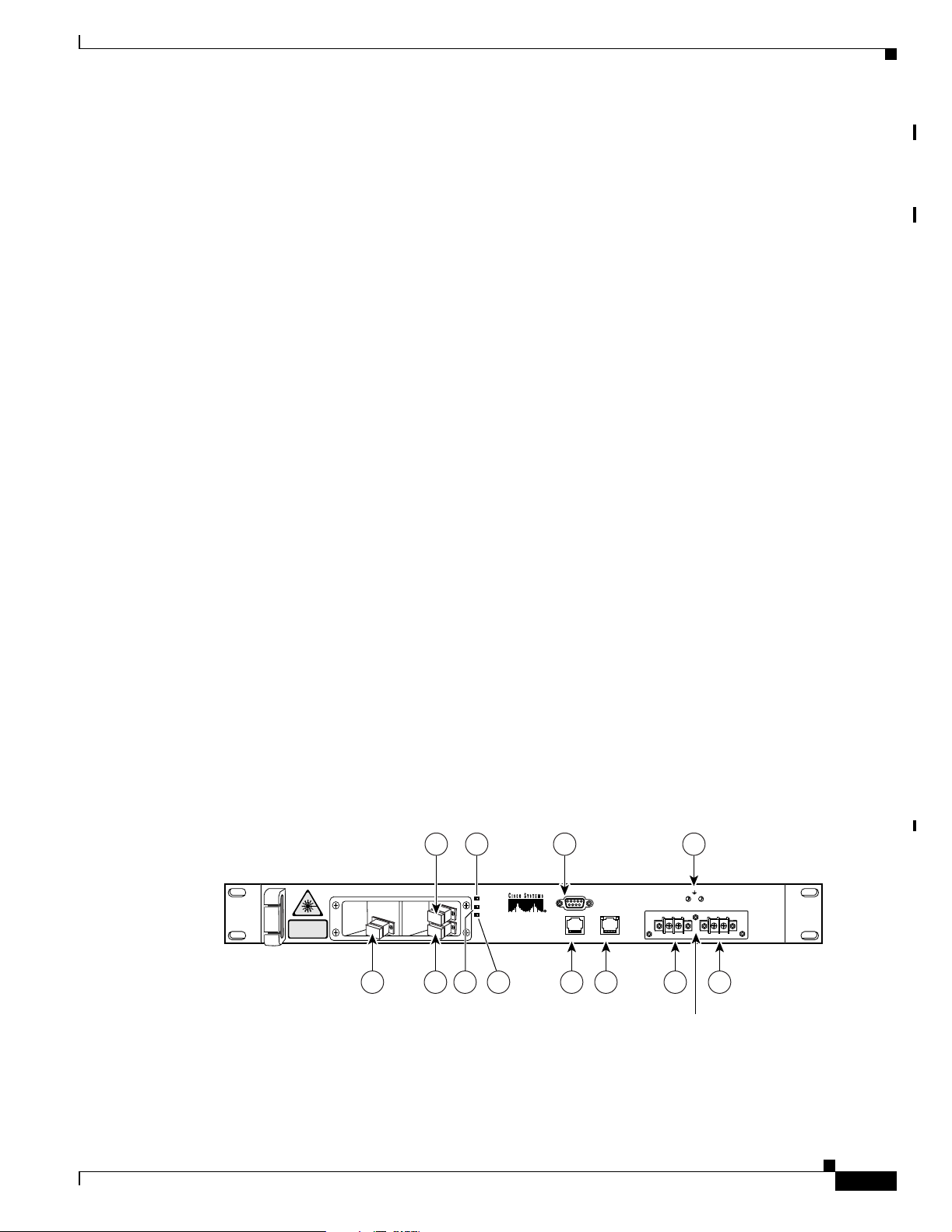
Figure 1-2 shows the Cisco ONS 15501 front panel. The front panel provides an all-front access
interface (fibers, power, alarm contact, and management) that complies with international standards.
Table 1-4 explains the front panel features.
Figure 1-2 Cisco ONS 15501 Front Panel
INVISIBLE LASER RADIATION.
DO NOT VIEW DIRECTLY WITH
OPTICAL INSTRUMENTS.
CLASS 1M LASER PRODUCT.
1 8 9 11 112 6
53 7 10
POWER
FAIL
LOS
Cisco ONS 15501
RS-232
ALARM OUT
-48V
LAN
4
-48V RET
RET
68377
78-14134-02, Release 2.0
DC connectors shown
with cover removed
Cisco ONS 15501 User Guide
1-7
Page 24

Cisco ONS 15501 Front Panel
Table 1-4 Cisco ONS 15501 Front Panel Features
Feature Description
1. Output monitor (connector) Provides spectrum monitoring of the Cisco ONS 15501
2. Output (connector) Provides output to an optical fiber cable and uses an SC/
3. Input (connector) Provides optical fiber cable access to the input of the
4. Fail (red LED) Indicates a major failure, such as the pump laser, power
5. Power (green LED) Indicates the unit is receiving normal operating power.
6. LOS (loss of signal) (yellow LED) Indicates a loss of input signal when the input signal falls
7. RS-232 (connector) Provides a console port for local monitoring of the
8. Alarm out (connector) Provides four pairs of dry contacts for an optional external
9. LAN (connector) Provides Ethernet access for connecting to a remote SNMP
10. Frame ground attachment Provides tapped-screw mounting holes for attaching a frame
11. Dual-circuit DC power input Provides two sets of DC input barrier strip terminals. The
Chapter 1 Product Overview
output and uses an SC/UPC type bulkhead connector.
(A shutter automatically closes when the cable is removed.)
UPC type standard connector. (A shutter automatically
closes when the cable is removed.)
Cisco ONS 15501 and uses an SC/UPC type standard connector. (This is a nonshuttered connector.)
supply, or the temperature level.
below the LOS threshold.
Cisco ONS 15501 and uses a DB-9 type female connector.
(See Appendix C, “Connector Pinouts.”) This port should
only be used for the evaluation of the unit by a trained technician. It is not designed for permanent connection.
alarm-monitoring system. Normally has closed contacts and
uses an RJ-45 type connector. (See Appendix C, “Connector
Pinouts.”)
monitoring location, and contains two LEDs. The left LED
(green) indicates that an Ethernet connection is established.
The right LED (yellow) indicates that a signal is being transmitted to the Ethernet. It uses an RJ-45 type connector.
ground lug and wiring.
right-hand strip terminal is for the primary DC power
wiring; the left-hand strip terminal is for an optional backup
DC power source. The left screw terminal of each strip is for
–48 VDC; the right screw terminal is for the return path.
1-8
Cisco ONS 15501 User Guide
78-14134-02, Release 2.0
Page 25

Chapter 1 Product Overview
Cisco ONS 15501 LED Alarm Definitions
The Cisco ONS 15501 front panel has three LEDs:
• The green POWER LED turns on or off to reflect the following conditions:
–
On: Both power supply voltages are within tolerance (the Cisco ONS 15501 is powered
normally).
–
Off: Both power supply voltages outside of tolerance or unit not powered up.
–
Blinking: One of the power supply voltages outside of tolerance.
• The red FAIL LED turns on or off to reflect the following conditions:
–
On: The pump laser bias, pump laser temperature, or power supply is out of tolerance. This LED
indicates a major internal failure, such as an overtemperature condition or a failure in the pump
laser or power supply.
–
Off: The pump laser bias, pump laser temperature, and power supply are in the specified range.
• The yellow LOS LED turns on or off to reflect the following conditions:
–
On: Input signal level is below the loss-of-input threshold.
–
Off: Input signal level is above the minimum input power threshold.
Cisco ONS 15501 Front Panel
78-14134-02, Release 2.0
Cisco ONS 15501 User Guide
1-9
Page 26

Cisco ONS 15501 Front Panel
Chapter 1 Product Overview
1-10
Cisco ONS 15501 User Guide
78-14134-02, Release 2.0
Page 27

CHAPTER
2
Installing the Cisco ONS 15501
This chapter describes the installation procedures for the Cisco ONS 15501 chassis and its components.
This chapter includes the following sections:
• Creating a Site Log, page 2-1
• Required Tools and Parts, page 2-2
• Installation Checklist, page 2-2
• Rack-Mounting the Chassis, page 2-3
• Optical Connection, page 2-3
• DC Power Connection, page 2-4
• Communication Connections, page 2-6
• Installation Commands, page 2-7
Before beginning any of the procedures in this document:
• Review the Regulatory Compliance and Safety Information for the Cisco ONS 15501 document to
avoid injury to yourself or damage to the equipment.
• Ensure that your equipment configuration meets the minimum requirements for the installation you
will perform, and that you have all the parts and tools you need.
Warning
Only trained and qualified personnel should be allowed to install, replace, or service this equipment.
Creating a Site Log
We recommend keeping a site log (or a section of a larger site log) to record all actions related to the
Cisco ONS 15501. The log should be kept near the chassis where anyone who works on the equipment
can access it. Site log entries might include the following:
• Background information.
• Installation progress.
Make a copy of the “Installation Checklist” section on page 2-2 and insert it into the site log. Make
entries on the checklist as you complete each procedure.
• Maintenance procedures.
78-14134-02, Release 2.0
Cisco ONS 15501 User Guide
2-1
Page 28

Required Tools and Parts
Use the site log as a record of ongoing system maintenance. Each time a procedure is performed on
the Cisco ONS 15501, update the site log to reflect situations such as maintenance schedules and
requirements, intermittent problems, changes and updates, configuration changes, and related
comments and notes.
Required Tools and Parts
You need the following tools and parts to install the Cisco ONS 15501:
• Phillips screwdriver
• Wire cutters, as needed (for DC power wiring)
• Wire strippers, as needed (for DC power wiring)
• Crimp tool (for grounding wire)
• Digital voltmeter (with ohmmeter function)
• Grounding wire (8 AWG)
• Power supply connection wire (18 AWG)
Chapter 2 Installing the Cisco ONS 15501
• Listed two-hole copper grounding lug (0.25 in. [0.635 cm] diameter bolt hole size, 0.625 in.
[1.5875 cm] center-to-center hole spacing)
Installation Checklist
The installation checklist includes the procedures for initial hardware installation of the
Cisco ONS 15501. Mark the entries as you complete each procedure. Make a copy of this checklist, as
needed, for the site log.
Installation checklist for site:
Product name:
Task Verified By Date
Background information placed in site log
Cisco printed documentation received
Cisco ONS 15501 received
Accessories received
Required tools available
Additional equipment available
Site power voltages verified
Initial electrical connections established
Cisco ONS 15501 fully installed
Operation verified
2-2
Cisco ONS 15501 User Guide
78-14134-02, Release 2.0
Page 29

Chapter 2 Installing the Cisco ONS 15501
Rack-Mounting the Chassis
The Cisco ONS 15501 mounts in a standard 19-inch, 23-inch, or ETSI equipment rack and occupies 1RU
(one rack unit is 1.75 inches) of vertical space. The unit is designed for front, middle, or rear mounting.
It is attached to the rack as shown in Figure 2-1.
Figure 2-1 Rack-Mounting the Cisco ONS 15501
Rack-Mounting the Chassis
Caution Use only the hardware provided with the Cisco ONS 15501. Failure to use the provided hardware
may result in unintended damage. If hardware is lost, contact Cisco Systems, Inc. for a replacement.
To install the Cisco ONS 15501 in a rack, follow these steps:
Step 1 Turn the Cisco ONS 15501 chassis so that the front panel is facing you.
Step 2 Determine the desired point of mounting and position the two mounting brackets accordingly.
Step 3 Attach the mounting brackets to the unit with the supplied screws using a Phillips screwdriver.
Step 4 Attach the unit to the rack with the supplied rack mounting screws using a Phillips screwdriver.
Optical Connection
Warning
Infra-red laser energy may be present on the cable connected to the receiving (input) connector.
The transmitting (output) optical fiber connector and the monitoring (output monitor) connector
are equipped with shutters that automatically close when a cable is removed. To avoid potential
damage to the eyes, do not look directly into an optical fiber cable or a connector (whether
shuttered or not). When an optical cable is not attached, place the supplied protective cap over
the cable’s connector. The output monitor output connector should be capped when not in use.
Front panel
68378
78-14134-02, Release 2.0
Cisco ONS 15501 User Guide
2-3
Page 30

DC Power Connection
Chapter 2 Installing the Cisco ONS 15501
Warning
Invisible laser radiation may be emitted from the end of the unterminated fiber cable or connector. Do
not stare into the beam or view directly with optical instruments. Viewing the laser output with
certain optical instruments (for example, eye loupes, magnifiers, and microscopes) within a distance
of 100 mm may pose an eye hazard. Use of controls or adjustments or performance of procedures other
than those specified may result in hazardous radiation exposure.
To connect the customer-supplied optical fiber cable to the SC/UPC optical ports, follow these steps:
Step 1 Connect the input optical fiber cable to the input connector (see Figure 2-2). Avoid making sharp bends
in the cable.
Step 2 Connect the output optical fiber cable to the output connector (see Figure 2-2). Avoid making sharp
bends in the cable.
Figure 2-2 Cisco ONS 15501 Optical Connections
1 2
RS-232
ALARM OUT
-48V
RET
LAN
DC connectors shown
with cover removed
-48V RET
68379
INVISIBLE LASER RADIATION.
DO NOT VIEW DIRECTLY WITH
OPTICAL INSTRUMENTS.
CLASS 1M LASER PRODUCT.
POWER
FAIL
LOS
Cisco ONS 15501
3
1 Output monitor 3 Output connector
2 Input connector
DC Power Connection
The section describe how to ground the chassis and then connect DC power to it.
Caution Check the power at your site to ensure that you are receiving clean power (free of spikes and noise).
Install a power conditioner, if necessary, to ensure proper voltages and power levels in the source
voltage.
Caution Use only the hardware provided with the Cisco ONS 15501. Failure to use the provided hardware
may result in unintended damage. If hardware is lost, contact Cisco Systems for a replacement.
Caution The protective cover for the DC power terminals should be installed at all times when the equipment
is energized, except for any necessary maintenance or troubleshooting.
2-4
Cisco ONS 15501 User Guide
78-14134-02, Release 2.0
Page 31

Chapter 2 Installing the Cisco ONS 15501
DC Power Connection
Warning
When installing or replacing the unit, the ground connection must always be made first and
disconnected last.
Grounding the Chassis
To connect the provided grounding lug to the tapped frame grounding holes and connect the
customer-supplied grounding wire to the DC power terminal connectors, follow these steps:
Step 1 Verify that the primary and user-optional redundant external DC power circuits are disconnected at the
source.
Step 2 Remove the cover from the DC power terminal connectors. Identify the two tapped frame grounding
holes at the upper right side of the Cisco ONS 15501 front panel. (See Figure 2-3.)
Step 3 Remove the two screws provided for securing the ground lug to the Cisco ONS 15501.
Step 4 Connect the 8 AWG grounding wire to the grounding lug. The other end of the wire should be suitably
grounded.
Step 5 Install the grounding lug on the Cisco ONS 15501, using the two provided screws and washers.
Step 6 Test for proper frame ground using the ohmmeter section of a digital voltmeter. Place one prod on the
Cisco ONS 15501 and the other on the frame grounding bus to which the grounding lug and grounding
wire is connected. Observe for a zero-resistance ground.
Note There is an alternate grounding point on the chassis, located on the left side of the rear panel.
Connecting the Power
To connect the power wiring to the DC power terminal connectors, follow these steps:
Step 1 Cut and strip the customer-supplied 8 AWG primary and redundant power supply wires, if necessary.
Identify the -48 VDC wire and power return wire for the primary and redundant circuit.
Step 2 Install the primary DC power wiring to the right-hand barrier strip. (See Figure 2-3.) The left-hand screw
is the -48 V connection. The right-hand screw, marked “RET,” is the ground connection.
Step 3 Install the redundant DC power wiring to the left-hand barrier strip. (See Figure 2-3.) The left-hand
screw is the -48 V connection. The right-hand screw, marked “RET,” is the ground connection.
Step 4 Replace the power connector cover.
Step 5 Apply power to the primary and redundant DC circuits.
78-14134-02, Release 2.0
Cisco ONS 15501 User Guide
2-5
Page 32

Communication Connections
Figure 2-3 Connecting the Cisco ONS 15501 to a DC Power Source
Chapter 2 Installing the Cisco ONS 15501
2
1 3
-48V
RET
-48V RET
Redundant DC power
1 Primary DC power connections 3 Redundant DC power connections
2 Tapped frame grounding holes
Communication Connections
The Cisco ONS 15501 communicates in three ways:
• SNMP (through Ethernet)
68380
2-6
• alarm contacts (through RJ-45 connector)
• console port (through RS-232)
See Appendix C, “Connector Pinouts”for the wiring layouts of the RJ-45 and RS-232 connectors.
See the “Configuring Local Serial Communication” section on page 3-1 for detailed information about
the RS-232 console port.
Cisco ONS 15501 User Guide
78-14134-02, Release 2.0
Page 33

Chapter 2 Installing the Cisco ONS 15501
Setting Up Alarm Contacts
To set up alarm contacts, follow these steps:
Step 1 Obtain an 8-conductor, 8 AWG solid-wire cable and terminate one end with an RJ-45 connector.
Step 2 Connect the stub end of the alarm cable to the alarm system contacts, either to miscellaneous discrete
inputs on terminal equipment or to a central office alarm panel.
Step 3 Connect the RJ-45 connector to the Cisco ONS 15501.
See the“Alarm Contact Closures” section on page 3-4 and the “Cisco ONS 15501 LED Alarm
Definitions” section on page 1-9.
Installation Commands
You can connect to a Cisco ONS 15501 locally using a serial connection or remotely through SNMP. See
the “Configuring Local Serial Communication” section on page 3-1 for instructions on setting up either
of these options. After you establish a connection, use the following commands to complete the hardware
installation. See Chapter 4, “Command Reference,” for a complete list of available commands.
Installation Commands
Introductory Commands
You can use the following commands to establish communication with the Cisco ONS 15501 and to
access additional information about the amplifier.
• help — Displays a list of all available commands
• sys-info — Displays the basic information on the system, including CLEI (Common Language
Equipment Identifier) code, model number, serial number, MAC address, firmware version, and
firmware build date
Review and Operational Commands
You can use the following commands to review the overall status of the Cisco ONS 15501.
• alarm — Displays a list of alarms in the system
• status — Displays the measured, alarm mean, and alarm trigger values for input power, internal case
temperature, optical gain, and output signal power, as well as the measured values for optical output
power
78-14134-02, Release 2.0
Cisco ONS 15501 User Guide
2-7
Page 34

Installation Commands
Chapter 2 Installing the Cisco ONS 15501
2-8
Cisco ONS 15501 User Guide
78-14134-02, Release 2.0
Page 35

Configuring the Cisco ONS 15501
The Cisco ONS 15501 supports monitoring using CLI commands from the console port. It also supports
remote monitoring using SNMP or Telnet (using TCP/IP over the Ethernet).
This chapter describes how to set up communications with a Cisco ONS 15501 and includes the
following sections:
• Configuring Local Serial Communication, page 3-1
• Monitoring Alarms and Traps, page 3-2
• Upgrading the Flash Image, page 3-3
• Configuring Remote Communication, page 3-3
• Alarm Contact Closures, page 3-4
Configuring Local Serial Communication
CHAPTER
3
To establish a serial communication link with a Cisco ONS 15501, the unit must first be properly
installed and powered up. Tab le 3-1 lists the equipment required for setup.
Table 3-1 Equipment for Local Serial Communication Setup
Hardware Comments
PC or Laptop Customer-supplied
RS-232 cable with DB-9 connectors (see
Appendix C, “Connector Pinouts”)
Setting Up the Software
To set up the software on the Cisco ONS 15501 for local serial communication, follow these steps:
Step 1 Launch the serial port communication utility on the PC or laptop and configure it to communicate at
9600 baud, no parity, 8 bit data, 1 stop bit, and no flow control.
Step 2 Connect the DB-9 end of the RS-232 data cable to the COM port on the PC or laptop.
Customer-supplied
78-14134-02, Release 2.0
Cisco ONS 15501 User Guide
3-1
Page 36

Monitoring Alarms and Traps
Step 3 Connect the other end of the RS-232 data cable to the RS-232 serial port on the Cisco ONS 15501 front
panel. (See Figure 1-2 on page 1-7.)
Step 4 Press Enter to get the login prompt.
The Cisco ONS 15501 is now ready for basic system configuration.
Configuring a Basic System
To configure a basic system, follow these steps:
Step 1 Log in to the system using the default master password edfa1.
Step 2 Enter host-config hostname to set the host name. The maximum allowed length for hostname is
15 characters.
Step 3 Enter ip-config ip-addr ip-subnet-mask def-gateway-ip to set the IP address, subnet mask, and gateway
address. In the absence of any arguments for subnetmask and gateway address, default values are
inserted.
Chapter 3 Configuring the Cisco ONS 15501
Step 4 Enter ntp status to enable the NTP, if appropriate, and enter ntp-ip ip-addr1 ip-addr2 to set the IP
address of the NTP server.
Step 5 Enter set-time time to set the time of the system if no NTP server is available. The time needs to be in
the same format as this example, where PST is the time zone.
Fri Aug 24 10:50:31 2001 PST.
Note See Appendix D, “Time Zone Codes,” for a list of time zones and correlating abbreviations.
Step 6 Enter set-user-pwd to set the user login password. The CLI then prompts the user for the default master
password and the new user password. The default user password is edfa.
Step 7 Enter set-master-pwd to set a new master password if you logged in using the master password. The
CLI prompts the user for the default master password and the new master password. The default master
password is edfa1.
Monitoring Alarms and Traps
To configure the software on the Cisco ONS 15501 for console port-based monitoring, follow these
steps:
3-2
Step 1 Enter show-trap to display the traps of the system.
Step 2 Enter alarm to display the alarms in the system.
Step 3 Enter status to check the optical and environmental status of the system.
Cisco ONS 15501 User Guide
78-14134-02, Release 2.0
Page 37

Chapter 3 Configuring the Cisco ONS 15501
Upgrading the Flash Image
To perform a field upgrade of a Flash image, follow these steps:
Step 1 Ensure that the IP addresses and the FTP servers, user accounts, path names, and filenames of the Flash
image are correctly set up.
Step 2 Enter show-trap to verify that the trap display is turned on.
Step 3 Enter sw-download ftp server-IP username password path filename flashbank or sw-download tftp
server-IP filename flashbank to FTP (TFTP) the image from the FTP (TFTP) server and burn it to the
specified Flash bank. Make sure that the FTP (TFTP) server is accessible using the same username,
password, path name, and filename.
Note Two traps are generated to indicate the beginning and ending of the FTP burn process. The image
cannot be downloaded to a currently active bank.
Step 4 Once the sw-download ftp process is complete, enter boot-bank flashbank to set the boot bank from
which the system next boots up.
Upgrading the Flash Image
Step 5 Enter reboot to reboot the system.
Configuring Remote Communication
To establish a remote communication link with a Cisco ONS 15501 through Telnet or SNMP, the unit
must first be properly installed and powered up.
Configuring for Telnet
When the Cisco ONS 15501's Ethernet port is connected to other Ethernet switches for network
management purposes, it is recommended that either end of the Ethernet port NOT be configured in
auto-negotiation mode, and that both ends of the Ethernet connection be configured in either 10 Mbps
or 100 Mbps, half or full duplex mode.
Note The 15501 default Ethernet boot mode is half-duplex 10 Mbps.
For additional information, please refer to the ethmode command.
To configure the Cisco ONS 15501 for Telnet, follow these steps:
Step 1 Connect the Cisco ONS 15501 to an Ethernet LAN using a standard RJ-45 cable.
Step 2 Make sure that the system network is properly set up using ping to the IP address of the system.
Step 3 Enter telnet target-ip-address to log in remotely to the Cisco ONS 15501.
78-14134-02, Release 2.0
Cisco ONS 15501 User Guide
3-3
Page 38

Alarm Contact Closures
Note All commands supported by the Cisco ONS 15501 through the console port are also supported in a
Telnet session.
Configuring for SNMP
When the Cisco ONS 15501's Ethernet port is connected to other Ethernet switches for network
management purposes, it is recommended that either end of the Ethernet port NOT be configured in
auto-negotiation mode, and that both ends of the Ethernet connection be configured in either 10 Mbps
or 100 Mbps half or full duplex mode.
Note The 15501 default Ethernet boot mode is half-duplex 10 Mbps.
For additional information, please refer to the ethmode command.
To configure the Cisco ONS 15501 for SNMP, follow these steps:
Chapter 3 Configuring the Cisco ONS 15501
Step 1 Connect the Cisco ONS 15501 to an Ethernet LAN using a standard RJ-45 cable.
Step 2 Enter add-snmp-mgr manager-ip to set the SNMP manager IP addresses. The maximum number of
SNMP manager IP addresses is 16.
Step 3 Enter get-snmp-mgr to display the list of SNMP managers.
Step 4 Enter del-snmp-mgr manager-ip to delete an SNMP manager entry.
Step 5 Enter add-snmp-com community-string [ro | rw] to set the SNMP community string for remote
monitoring. The maximum number of SNMP community strings is 16.
Step 6
Step 7 Enter del-snmp-com community-string to delete an SNMP community strings entry.
Enter get-snmp-com to display the list of SNMP community strings.
Alarm Contact Closures
The Cisco ONS 15501 provides a front panel, single form C, discrete external alarm output. (See the
“Cisco ONS 15501 Front Panel” section on page 1-7 for additional information.) The external alarm
output is through the eight wires of an RJ-45 connector.
The following events are reported by the discrete external alarms through individual alarm contacts:
• Alarm 1—Loss of input signal or input signal power below threshold
• Alarm 2—Failure in the pump laser or pump laser temperature
• Alarm 3—Loss of input power supply or power supply out of range
3-4
• Alarm 4—Undefined (always on; may be used for power indication)
Note The default state of the alarm contacts is Normally Closed. Depending on which fault condition occurs,
specific alarm contacts open. The corresponding Cisco ONS 15501 LEDs turn on/off. (See the “Cisco
ONS 15501 LED Alarm Definitions” section on page 1-9 for additional information.)
Cisco ONS 15501 User Guide
78-14134-02, Release 2.0
Page 39

Chapter 3 Configuring the Cisco ONS 15501
Table 3-2 lists the RJ-45 pinouts for the alarms.
Table 3-2 Alarm Pinouts
Pinout Alarm
1 Alarm 1+ (power)
2Alarm 13 Alarm 2+ (major)
4Alarm 2-
5 Alarm 3+ (minor)
6Alarm 37 Alarm 4+ (no connection)
8Alarm 4-
Alarm Contact Closures
78-14134-02, Release 2.0
Cisco ONS 15501 User Guide
3-5
Page 40

Alarm Contact Closures
Chapter 3 Configuring the Cisco ONS 15501
3-6
Cisco ONS 15501 User Guide
78-14134-02, Release 2.0
Page 41

CHAPTER
4
Command Reference
This chapter describes the commands used in the Cisco ONS 15501 environment. The commands are
listed alphabetically.
Note To display a list of available commands, enter help. To obtain the syntax for any individual command,
enter help [command].
Note All commands are case insensitive.
Note Commands that change the configuration of the control module are protected by the master password.
Commands that allow access to information but do not change the configuration are protected by the
user password.
78-14134-02, Release 2.0
Cisco ONS 15501 User Guide
4-1
Page 42

add-snmp-com
add-snmp-com
To add an SNMP community string to the system, use the add-snmp-com command.
add-snmp-com community-string [ro|rw]
Chapter 4 Command Reference
Syntax Description
Defaults ro is the default if access mode is not specified.
Command Types Changes configuration
Command Modes Master password protected
Command History
Usage Guidelines The Cisco ONS 15501 supports up to 16 SNMP community strings.
community-string Specifies the SNMP community string to be added to the system. The
string can be comprised of any alphanumeric combination. The
maximum number of characters allowed is 21.
[ro|rw] Specifies read only or both read and write access associated with the
community string.
Release Modification
EDFA 1.0 This command was introduced.
Examples The following example shows how to add an SNMP community string to the system.
edfa > add-snmp-com abcd
Related Commands
Cisco ONS 15501 User Guide
4-2
Command Description
del-snmp-com Deletes an SNMP community string in the system.
get-snmp-com Displays an SNMP community string in the system.
78-14134-02, Release 2.0
Page 43

Chapter 4 Command Reference
add-snmp-mgr
To add or modify an SNMP manager entry on the system, use the add-snmp-mgr command.
add-snmp-mgr manager-ip
add-snmp-mgr
Syntax Description
Defaults None
Command Types Changes configuration
Command Modes Master password protected
Command History
Usage Guidelines The Cisco ONS 15501 uses the SNMP manager address to direct SNMP trap and inform notifications.
manager-ip Specifies the IP address of the host running the SNMP manager.
Release Modification
EDFA 1.0 This command was introduced.
No notifications are sent unless at least one SNMP manager address is configured. The
Cisco ONS 15501 accepts a maximum of 16 IP managers.
Examples The following example shows how to add an SNMP manager entry on the system.
edfa > add-snmp-mgr 10.1.2.71
Related Commands
78-14134-02, Release 2.0
Command Description
del-snmp-mgr Deletes an SNMP manager entry on the system.
get-snmp-mgr Displays an SNMP manager entry on the system.
Cisco ONS 15501 User Guide
4-3
Page 44

alarm
alarm
Chapter 4 Command Reference
To display a list of alarms in the system, use the alarm command.
alarm
Syntax Description
This command has no other arguments or keywords.
Defaults None
Command Types Does not change configuration
Command Modes User password protected
Command History
Release Modification
EDFA 1.0 This command was introduced.
Examples The following example shows how to display a list of alarms in the system.
edfa > alarm
Alarm: Temperature - Unacceptable
Alarm: Equipment Alarm: Input Signal - Low
4-4
Cisco ONS 15501 User Guide
78-14134-02, Release 2.0
Page 45

Chapter 4 Command Reference
boot-bank
boot-bank
To display the active and planned boot bank or modify the active boot bank, use the boot-bank
command.
boot-bank [flash-bank]
Syntax Description
flash-bank Specifies the Flash bank from which the system is booted. This should
be 1, 2, or 3.
Defaults Displays the active boot bank
Command Types Changes configuration
Command Modes Master password protected
Command History
Release Modification
EDFA 1.0 This command was introduced.
Usage Guidelines The active boot bank is the Flash bank from which the system has been booted. The planned boot bank
is the Flash bank from which the system will next be booted.
Examples The following example shows how to modify the active boot bank.
edfa > boot-bank 2
The following example shows how to display the active boot bank.
edfa > boot-bank
Active flash bank number: 1
Planned flash bank number: 1
78-14134-02, Release 2.0
Cisco ONS 15501 User Guide
4-5
Page 46

copyright
copyright
Chapter 4 Command Reference
This command displays the copyright information
copyright
Syntax Description
This command has no other arguments or keywords.
Defaults None
Command Types Does not change configuration
Command Modes User password protected
Command History
Release Modification
EDFA 2.0 This command was introduced.
Examples The following example shows the copyright information.
edfa > copyright
Copyright 2002 Motorola
Based on software developed by, licensed under or Copyright by one or more of
- GNU General Public License Version 2, June 1991
- Carnegie Mellon University
- Regents of the University of California
- Freeware developed by a variety a lot of other developers.
4-6
Cisco ONS 15501 User Guide
78-14134-02, Release 2.0
Page 47

Chapter 4 Command Reference
del-snmp-com
To delete an SNMP community string on the system, use the del-snmp-com command.
del-snmp-com community-string
del-snmp-com
Syntax Description
Defaults None
Command Types Changes configuration
Command Modes Master password protected
Command History
Examples The following example shows how to delete an SNMP community string on the system.
Related Commands
community-string Specifies the SNMP community string to be deleted from the system.
Release Modification
EDFA 1.0 This command was introduced.
edfa > del-snmp-com abcd
Command Description
add-snmp-com Adds an SNMP community string to the system.
get-snmp-com Displays an SNMP community string on the system.
78-14134-02, Release 2.0
Cisco ONS 15501 User Guide
4-7
Page 48

del-snmp-mgr
del-snmp-mgr
To delete an SNMP manager entry on the system, use the del-snmp-mgr command.
Chapter 4 Command Reference
del-snmp-mgr manager-ip
Syntax Description
Defaults None
Command Types Changes configuration
Command Modes Master password protected
Command History
Usage Guidelines The Cisco ONS 15501 uses the SNMP manager address to direct SNMP trap and inform notifications.
Examples The following example shows how to delete an SNMP manager entry on the system.
manager-ip Specifies the IP address of the host running the SNMP manager.
Release Modification
EDFA 1.0 This command was introduced.
No notifications are sent unless at least one SNMP manager address is configured.
edfa > del-snmp-mgr 10.1.2.71
Related Commands
Cisco ONS 15501 User Guide
4-8
Command Description
add-snmp-mgr Adds or modifies an SNMP manager entry.
get-snmp-mgr Displays SNMP manager entry information.
78-14134-02, Release 2.0
Page 49

Chapter 4 Command Reference
ethmode
ethmode
To display or modify the Ethernet boot mode, use the ethmode command.
ethmode mode
Syntax Description
mode Specifies the Ethernet boot mode. The boot mode is specified as 0
for auto-sense; 1 for full-duplex 100 Mbps; 2 for half-duplex 100
Mbps; 3 for full-duplex 10 Mbps; or 4 for half-duplex 10 Mbps.
Defaults Displays the current Ethernet boot mode.
Command Types Changes configuration
Command Modes Master password protected
Command History
Release Modification
EDFA 1.0 This command was introduced.
Usage Guidelines The system default Ethernet boot mode is 4 for half-duplex 10 Mbps.
After setting a new Ethernet boot mode, the system must be rebooted to effect the change.
Examples The following example shows how to display the Ethernet boot mode.
edfa > ethmode
ethernet init-mode 4
The following example shows how to modify the Ethernet boot mode.
edfa > ethmode 3
ethernet init-mode updated to 3
Cisco ONS 15501 User Guide
78-14134-02, Release 2.0
4-9
Page 50

gain
gain
Chapter 4 Command Reference
To display the measured optical signal gain, use the gain command.
gain
Syntax Description
Defaults None
Command Types Does not change configuration
Command Modes User password protected
Command History
Usage Guidelines The value for measured optical signal gain is displayed in dB.
Examples The following example shows how to display the measured optical signal gain.
This command has no other arguments or keywords.
Release Modification
EDFA 1.0 This command was introduced.
edfa > gain
17.50 (dB)
Related Commands
Cisco ONS 15501 User Guide
4-10
Command Description
gainmean Displays the configured signal gain and alarm mean level.
gaintrig Displays the gain alarm trigger level.
resetmeantrig Resets the signal gain and alarm mean level, gain alarm trigger level, optical
input alarm mean level, optical input alarm trigger level, output signal alarm
mean level, output signal alarm trigger level, internal case temperature
alarm mean level, and internal case temperature alarm trigger level to the
manufacturer’s default settings.
setgainmean Sets the signal gain and alarm mean level.
setgaintrig Sets the gain alarm trigger level.
78-14134-02, Release 2.0
Page 51

Chapter 4 Command Reference
gainmean
gainmean
To display the configured signal gain and alarm mean level, use the gainmean command.
gainmean
Syntax Description
Defaults None
Command Types Does not change configuration
Command Modes User password protected
Command History
Usage Guidelines The value for configured Cisco ONS 15501 signal gain and alarm mean level is displayed in dB.
Examples The following example shows how to display the configured signal gain and alarm mean level.
This command has no other arguments or keywords.
Release Modification
EDFA 1.0 This command was introduced.
edfa > gainmean
17.50 (dB)
Related Commands
78-14134-02, Release 2.0
Command Description
gain Displays the measured optical signal gain.
gaintrig Displays the gain alarm trigger level.
resetmeantrig Resets the signal gain and alarm mean level, gain alarm trigger level, optical
input alarm mean level, optical input alarm trigger level, output signal alarm
mean level, output signal alarm trigger level, internal case temperature
alarm mean level, and internal case temperature alarm trigger level to the
manufacturer’s default settings.
setgainmean Sets the signal gain and alarm mean level.
setgaintrig Sets the gain alarm trigger level.
Cisco ONS 15501 User Guide
4-11
Page 52

gaintrig
gaintrig
Chapter 4 Command Reference
To display the gain alarm trigger level, use the gaintrig command.
gaintrig
Syntax Description
Defaults None
Command Types Does not change configuration
Command Modes User password protected
Command History
Usage Guidelines The value for Cisco ONS 15501 gain alarm trigger level is displayed in dB.
Examples The following example shows how to display the gain alarm trigger level.
This command has no other arguments or keywords.
Release Modification
EDFA 1.0 This command was introduced.
edfa > gaintrig
1.00 (dB)
Related Commands
Cisco ONS 15501 User Guide
4-12
Command Description
gain Displays the measured optical signal gain.
gainmean Displays the configured signal gain and alarm mean level.
resetmeantrig Resets the signal gain and alarm mean level, gain alarm trigger level, optical
input alarm mean level, optical input alarm trigger level, output signal alarm
mean level, output signal alarm trigger level, internal case temperature
alarm mean level, and internal case temperature alarm trigger level to the
manufacturer’s default settings.
setgainmean Sets the signal gain and alarm mean level.
setgaintrig Sets the gain alarm trigger level.
78-14134-02, Release 2.0
Page 53

Chapter 4 Command Reference
get-snmp-com
To display the SNMP community strings in the system, use the get-snmp-com command.
get-snmp-com community-string
get-snmp-com
Syntax Description
community-string Specifies the SNMP community string to be displayed.
Defaults Displays all SNMP community strings in the system
Command Types Does not change configuration
Command Modes Master password protected
Command History
Release Modification
EDFA 1.0 This command was introduced.
Examples The following example shows how to display an SNMP community string in the system.
edfa > get-snmp-com abcd
A list of the SNMP community string
=======================================
private
abcd
Related Commands
78-14134-02, Release 2.0
Command Description
add-snmp-com Adds an SNMP community string to the system.
del-snmp-com Deletes an SNMP community string on the system.
Cisco ONS 15501 User Guide
4-13
Page 54

get-snmp-mgr
get-snmp-mgr
To display the SNMP (Simple Network Management Protocol) manager entries on the system, use the
get-snmp-mgr command.
Chapter 4 Command Reference
get-snmp-mgr
Syntax Description
manager-ip Specifies the IP address of the host running the SNMP manager.
Defaults Displays all IP values of the SNMP manager
Command Types Does not change configuration
Command Modes User password protected
Command History
Release Modification
EDFA 1.0 This command was introduced.
Usage Guidelines Use this command to display SNMP manager configuration information for a single entry or for all
entries on the system.
Examples The following example shows how to display the values of SNMP managers.
edfa > get-snmp-mgr 10.1.2.71
A list of the SNMP manager IP addresses
===========================================
209.128.68.147
10.1.2.71
Related Commands
Cisco ONS 15501 User Guide
4-14
Command Description
add-snmp-mgr Adds or modifies an SNMP manager entry.
del-snmp-mgr Deletes an SNMP manager entry.
78-14134-02, Release 2.0
Page 55

Chapter 4 Command Reference
help
help
To display the syntax for an individual command, or to display a list of available user commands, use
the help command.
help [command]
Syntax Description
command Specifies the command
Defaults Displays a list of available user commands
Command Types Does not change configuration
Command Modes User password protected
Command History
Release Modification
EDFA 1.0 This command was introduced.
Usage Guidelines If there is a command specified, the corresponding help for that command will be printed. Without any
command specified, a list of all commands will be shown.
Examples The following example shows how to access a list of available user password commands.
edfa > help
STATUS: Alarm, Gain, GainMean, GainTrig, InPwr, InPwrMean, InPwrTrig,
OptOutPwr, OutSigPwr, OutSigPwrMean, OutSigPwrTrig, Ps1, Ps2,
Status, Temp, TempMean, TempTrig
78-14134-02, Release 2.0
SYSTEM: copyright, ethmode, get-snmp-mgr, help, host-config, ip-config,
logout, neighbor-in, neighbor-out, ntp, ntp-ip, sys-info, time,
timeout, timezone
MAINTENANCE: hide-trap, show-trap
Cisco ONS 15501 User Guide
4-15
Page 56

help
Chapter 4 Command Reference
The following example shows how to access a list of available master password commands.
edfa > help
STATUS:Alarm, Gain, GainMean, GainTrig, InPwr, InPwrMean, InPwrTrig,
LaserPumpStat, OptOutPwr, OutSigPwr, OutSigPwrMean, OutSigPwrTrig,
Ps1, Ps2, Status, Temp, TempMean, TempTrig
SETUP:ResetMeanTrig, SetGainMean, SetGainTrig, SetInPwrMean,
SetInPwrTrig, SetOutSigPwrMean, SetOutSigPwrTrig, SetTempMean,
SetTempTrig
SYSTEM:add-snmp-com, add-snmp-mgr, copyright, del-snmp-com, del-snmp-mgr,
ethmode, get-snmp-com, get-snmp-mgr, help, host-config, ip-config,
logout, neighbor-in, neighbor-out, ntp, ntp-ip, ping,
set-master-pwd, set-time, set-user-pwd, sys-info, time, timeout,
timezone
MAINTENANCE:boot-bank, hide-trap, reboot, show-trap, sw-download
4-16
Cisco ONS 15501 User Guide
78-14134-02, Release 2.0
Page 57

Chapter 4 Command Reference
hide-trap
hide-trap
To hide the trap message, use the hide-trap command.
hide-trap
Syntax Description
Defaults None
Command Types Changes configuration
Command Modes User password protected
Command History
Examples The following example shows how to hide the trap message.
Related Commands
This command has no other arguments or keywords.
Release Modification
EDFA 1.0 This command was introduced.
edfa > hide-trap
Command Description
show-trap Displays the trap message.
78-14134-02, Release 2.0
Cisco ONS 15501 User Guide
4-17
Page 58

host-config
host-config
Chapter 4 Command Reference
To display or modify the current host name, use the host-config command.
host-config [hostname]
Syntax Description
Defaults Displays the current host name
Command Types Changes configuration
Command Modes Master password protected. User password allows access to the current hostname, but does not allow
Command History
Usage Guidelines hostname can have a maximum of 15 characters. Only alphanumeric characters, hyphens, dots, and
hostname Specifies the host name.
modifications.
Release Modification
EDFA 1.0 This command was introduced.
underscores should be used.
Examples The following example shows how to modify the current host name.
edfa > host-config ADM-EAST
ADM-EAST >
Cisco ONS 15501 User Guide
4-18
78-14134-02, Release 2.0
Page 59

Chapter 4 Command Reference
inpwr
inpwr
To display the measured optical input power, use the inpwr command.
inpwr
Syntax Description
Defaults None
Command Types Does not change configuration
Command Modes User password protected
Command History
Usage Guidelines The value for optical input power is displayed in dBm.
Examples The following example shows how to display the optical input power.
This command has no other arguments or keywords.
Release Modification
EDFA 1.0 This command was introduced.
edfa > inpwr
-46.03 (dBm)
Related Commands
78-14134-02, Release 2.0
Command Description
inpwrmean Displays the optical input alarm mean level.
inpwrtrig Displays the optical input alarm trigger level.
resetmeantrig Resets the signal gain and alarm mean level, gain alarm trigger level, optical
input alarm mean level, optical input alarm trigger level, output signal alarm
mean level, output signal alarm trigger level, internal case temperature
alarm mean level, and internal case temperature alarm trigger level to the
manufacturer’s default settings.
setinpwrmean Sets the optical input alarm mean level.
setinpwrtrig Sets the optical input alarm trigger level.
Cisco ONS 15501 User Guide
4-19
Page 60

inpwrmean
inpwrmean
Chapter 4 Command Reference
To display the optical input alarm mean level, use the inpwrmean command.
inpwrmean
Syntax Description
Defaults None
Command Types Does not change configuration
Command Modes User password protected
Command History
Usage Guidelines The value for optical input alarm mean level is displayed in dBm.
Examples The following example shows how to display the optical input alarm mean level.
This command has no other arguments or keywords.
Release Modification
EDFA 1.0 This command was introduced.
edfa > inpwrmean
-38.00 (dBm)
Related Commands
Cisco ONS 15501 User Guide
4-20
Command Description
inpwr Displays the measured optical input power.
inpwrtrig Displays the optical input alarm trigger level.
resetmeantrig Resets the signal gain and alarm mean level, gain alarm trigger level, optical
input alarm mean level, optical input alarm trigger level, output signal alarm
mean level, output signal alarm trigger level, internal case temperature
alarm mean level, and internal case temperature alarm trigger level to the
manufacturer’s default settings.
setinpwrmean Sets the optical input alarm mean level.
setinpwrtrig Sets the optical input alarm trigger level.
78-14134-02, Release 2.0
Page 61

Chapter 4 Command Reference
inpwrtrig
inpwrtrig
To display the optical input alarm trigger level, use the inpwrtrig command.
inpwrtrig
Syntax Description
Defaults None
Command Types Does not change configuration
Command Modes User password protected
Command History
Usage Guidelines The value for optical input alarm trigger level is displayed in dBm
Examples The following example shows how to display the optical input alarm trigger level.
This command has no other arguments or keywords.
Release Modification
EDFA 1.0 This command was introduced.
edfa > inpwrtrig
1.00 (dBm)
Related Commands
78-14134-02, Release 2.0
Command Description
inpwr Displays the measured optical input power.
inpwrmean Displays the optical input alarm mean level.
resetmeantrig Resets the signal gain and alarm mean level, gain alarm trigger level, optical
input alarm mean level, optical input alarm trigger level, output signal alarm
mean level, output signal alarm trigger level, internal case temperature
alarm mean level, and internal case temperature alarm trigger level to the
manufacturer’s default settings.
setinpwrmean Sets the optical input alarm mean level.
setinpwrtrig Sets the optical input alarm trigger level.
Cisco ONS 15501 User Guide
4-21
Page 62

ip-config
ip-config
Chapter 4 Command Reference
To display or modify the IP address, IP subnet mask and IP default gateway, use the ip-config command.
ip-config [ip-addr [ip-subnet-mask [def-gateway-ip]]]
Syntax Description
ip-addr Specifies the IP address.
ip-subnet-mask Specifies the IP subnet mask.
def-gateway-ip Specifies the IP address of the default gateway.
Defaults If no values are entered, the command displays the current IP address, IP subnet mask and IP default
gateway.
If a value is entered for ip-addr, but not for ip-subnet-mask, the default IP subnet mask is 255.255.255.0.
If a value is entered for ip-addr, but not for def-gateway-ip, the default IP gateway is xx.yy.zz.1; where
xx.yy.zz are obtained by binary AND of first three bytes of ip-addr and ip-subnet-mask.
Command Types Changes configuration
Command Modes User password protected for display; master password protected for modification.
Command History
Release Modification
EDFA 1.0 This command was introduced.
Examples The following example shows how to display the IP address, IP subnet mask and IP default gateway.
edfa > ip-config
10.1.2.221 255.255.255.0 10.1.2.1
The following example shows how to display or modify the IP address, IP subnet mask and IP default
gateway.
edfa > ip-config 192.168.0.10 255.255.255.240 192.168.0.1
Cisco ONS 15501 User Guide
4-22
78-14134-02, Release 2.0
Page 63

Chapter 4 Command Reference
logout
logout
To log out of the system, use the logout command.
logout
Syntax Description
Defaults None
Command Types Does not change configuration
Command Modes User password protected
Command History
This command has no other arguments or keywords.
Release Modification
EDFA 1.0 This command was introduced.
78-14134-02, Release 2.0
Cisco ONS 15501 User Guide
4-23
Page 64

neighbor-in
neighbor-in
Chapter 4 Command Reference
To display or modify the neighboring equipment details for optical input, use the neighbor-in command.
neighbor-in [[host link-host] [ip link-ip] [port link-port]] | [disable]
Syntax Description
Defaults If no values are entered, the command displays the current input neighbor details.
Command Types Changes configuration
Command Modes User password protected for read. Master password protected for writes.
Command History
host link-host Specifies the hostname for input neighbor. The maximum length is
32 characters.
ip link-ip Specifies the IP address for input neighbor.
port link-port Specifies the name for the port on the remote host providing the input
optical signal. The maximum length is 32 characters.
Note If the host or ip keywords are not present, the port keyword
is not allowed.
disable Deletes the input neighbor information.
Note The disable option is not allowed with any other options.
Release Modification
EDFA 2.0 This command was introduced.
Usage Guidelines In the absence of all arguments, the configured input neighbor NE information is shown.
To include space characters in the host or port, use double quotes (for example, neighbor-in host
“DWDM phoenix 10”). Excluding the disable keyword, whenever a keyword present, the keyword
value must be given. Either host or ip are required while port is optional. The disable keyword deletes
the neighbor NE information.
Cisco ONS 15501 User Guide
4-24
78-14134-02, Release 2.0
Page 65

Chapter 4 Command Reference
Examples: The following example shows how to configure the input neighbor equipment information.
edfa > neighbor-in host box1 ip 192.168.0.4 port box1-port
edfa > neighbor-in host box1
edfa > neighbor-in ip 192.168.0.4
edfa > neighbor-in host box1 port box1-port
edfa > neighbor-in host box1 ip 192.168.0.4
edfa > neighbor-in ip 192.168.0.4 port box1-port
edfa > neighbor-in disable
edfa > neighbor-in
HOST: source1
PORT: out-2
IP ADDRESS: 10.1.5.41
The following example shows how to issue the neighbor-in command with all the parameters.
edfa > neighbor-in source1 ip 10.1.5.41 port out-2
edfa > neighbor-in
HOST: source1
PORT: out-2
IP ADDRESS: 10.1.5.41
neighbor-in
Related Commands Command Description
neighbor-out Displays and modifies the neighboring equipment information for optical
output.
78-14134-02, Release 2.0
Cisco ONS 15501 User Guide
4-25
Page 66

neighbor-out
neighbor-out
To display or modify the neighboring equipment details for optical output, use the neighbor-out
command.
Chapter 4 Command Reference
neighbor-out [[host link-host] [ip link-ip] [port link-port]] | [disable]
Syntax Description
Defaults If no values are entered, the command displays the current output neighbor details.
Command Types Changes configuration
Command Modes User password protected for read. Master password protected for writes.
Command History
host link-host Specifies the hostname for the output neighbor. The maximum length
is 32 characters.
ip link-ip Specifies the IP address for the output neighbor.
port link-port Specifies the name for the port on the remote host receiving the output
optical signal. The maximum length is 32 characters.
Note If the host or ip keywords are not present, the port keyword
is not allowed.
disable Deletes the input neighbor information.
Note The disable option is not allowed with any other options.
Release Modification
EDFA 2.0 This command was introduced.
Usage Guidelines In the absence of all arguments, the configured output neighbor NE information is shown.
To include space characters in the host or port, use double quotes (for example, neighbor-out host
“DWDM phoenix 10”). Excluding the disable keyword, whenever a keyword present, the keyword
value must be given. Either host or ip are required while port is optional. The disable keyword deletes
the neighbor NE information.
Cisco ONS 15501 User Guide
4-26
78-14134-02, Release 2.0
Page 67

Chapter 4 Command Reference
neighbor-out
Examples The following example shows how to configure the output neighbor equipment information.
edfa > neighbor-out host box1 ip 192.168.0.4 port box1-port
edfa > neighbor-out host box1
edfa > neighbor-out ip 192.168.0.4
edfa > neighbor-out host box1 port box1-port
edfa > neighbor-out host box1 ip 192.168.0.4
edfa > neighbor-out ip 192.168.0.4 port box1-port
edfa > neighbor-out disable
edfa > neighbor-out
IP ADDRESS: 10.1.71.41
The following example shows how to issue the neighbor in command with all the parameters.
edfa > neighbor-out dest1 ip 10.1.7.31 port in-1
edfa > neighbor-out
HOST: dest1
PORT: in-1
IP ADDRESS: 10.1.5.41
HOST: dest1
PORT: in-2
Related Commands Command Description
neighbor-in Displays and modifies the neighboring equipment information for optical
input.
78-14134-02, Release 2.0
Cisco ONS 15501 User Guide
4-27
Page 68

ntp
ntp
Chapter 4 Command Reference
To modify or display the NTP (Network Time Protocol) status for the system, use the ntp command.
ntp [status]
Syntax Description
status Specified as on to enable the NTP, or as off to disable the NTP.
Defaults Displays the current configuration of the NTP (that is, on or off), as well as the current IP addresses of
the primary and secondary NTP servers
Command Types Changes configuration
Command Modes User password protected for display; master password protected for modification.
Command History
Release Modification
EDFA 1.0 This command was introduced.
Usage Guidelines When the NTP is on, the status (up/down) of the NTP servers is displayed if no argument is provided for
the command.
Examples The following example shows how to enable the NTP for the system.
edfa > ntp on
The following example shows how to display the current configuration of the NTP.
edfa > ntp
ON, 209.128.68.149:UP, 209.128.68.147:DOWN
Related Commands
Command Description
ntp-ip Modifies the IP addresses of the NTP server.
Cisco ONS 15501 User Guide
4-28
78-14134-02, Release 2.0
Page 69

Chapter 4 Command Reference
ntp-ip
ntp-ip
To modify or display the IP addresses of the NTP (Network Time Protocol) server, use the ntp-ip
command.
ntp-ip [ip-addr1 [ip-addr2]]
Syntax Description
ip-addr1 Specifies the IP address of the primary NTP server.
ip-addr2 Specifies the IP address of the secondary NTP server.
Defaults Displays the current IP addresses of the primary and secondary NTP servers.
If only one value is entered, that value is applied to the IP address of the primary NTP server.
Command Types Changes configuration
Command Modes User password protected for display; master password protected for modification.
Command History
Release Modification
EDFA 1.0 This command was introduced.
Examples The following example shows how to modify the IP address of the primary NTP server.
edfa > ntp-ip 209.128.68.149 209.128.68.147
Related Commands
78-14134-02, Release 2.0
The following example shows how to display the current IP addresses of the primary and secondary NTP
servers.
edfa > ntp-ip
209.128.68.149, 209.128.68.147
Command Description
ntp Enables or disables the NTP for the system
Cisco ONS 15501 User Guide
4-29
Page 70

optoutpwr
optoutpwr
Chapter 4 Command Reference
To display the optical output power, use the optoutpwr command.
optoutpwr
Syntax Description
Defaults None
Command Types Does not change configuration
Command Modes User password protected
Command History
Usage Guidelines The value for optical output power is displayed in dBm.
Examples The following example shows how to display the optical output power .
This command has no other arguments or keywords.
Release Modification
EDFA 1.0 This command was introduced.
edfa > optoutpwr
-28.53 (dBm)
4-30
Cisco ONS 15501 User Guide
78-14134-02, Release 2.0
Page 71

Chapter 4 Command Reference
outsigpwr
outsigpwr
To display the calculated output signal power, use the outsigpwr command.
outsigpwr
Syntax Description
Defaults None
Command Types Does not change configuration
Command Modes User password protected
Command History
Usage Guidelines The value for calculated output signal power is displayed in dBm.
Examples The following example shows how to display the calculated output signal power.
This command has no other arguments or keywords.
Release Modification
EDFA 1.0 This command was introduced.
edfa > outsigpwr
-28.53 (dBm)
Related Commands
78-14134-02, Release 2.0
Command Description
outsigpwrmean Displays the output signal alarm mean level.
outsigpwrtrig Displays the output signal alarm trigger level.
resetmeantrig Resets the signal gain and alarm mean level, gain alarm trigger level, optical
input alarm mean level, optical input alarm trigger level, output signal alarm
mean level, output signal alarm trigger level, internal case temperature
alarm mean level, and internal case temperature alarm trigger level to the
manufacturer’s default settings.
setoutsigpwrmean Sets the output signal alarm mean level.
setoutsigpwrtrig Sets the output signal alarm trigger level.
Cisco ONS 15501 User Guide
4-31
Page 72

outsigpwrmean
outsigpwrmean
To display the output signal alarm mean level, use the outsigpwrmean command.
outsigpwrmean
Chapter 4 Command Reference
Syntax Description
Defaults None
Command Types Does not change configuration
Command Modes User password protected
Command History
Usage Guidelines The value for output signal alarm mean level is displayed in dBm.
Examples The following example shows how to display the output signal alarm mean level.
This command has no other arguments or keywords.
Release Modification
EDFA 1.0 This command was introduced.
edfa > outsigpwrmean
2.00 (dBm)
Related Commands
Cisco ONS 15501 User Guide
4-32
Command Description
outsigpwr Displays the calculated output signal power.
outsigpwrtrig Displays the output signal alarm trigger level.
resetmeantrig Resets the signal gain and alarm mean level, gain alarm trigger level, optical
input alarm mean level, optical input alarm trigger level, output signal alarm
mean level, output signal alarm trigger level, internal case temperature
alarm mean level, and internal case temperature alarm trigger level to the
manufacturer’s default settings.
setoutsigpwrmean Sets the output signal alarm mean level.
setoutsigpwrtrig Sets the output signal alarm trigger level.
78-14134-02, Release 2.0
Page 73

Chapter 4 Command Reference
outsigpwrtrig
To display the output signal alarm trigger level, use the outsigpwrtrig command.
outsigpwrtrig
outsigpwrtrig
Syntax Description
Defaults None
Command Types Does not change configuration
Command Modes User password protected
Command History
Usage Guidelines The value for output signal alarm trigger level is displayed in dBm.
Examples The following example shows how to display the output signal alarm trigger level.
This command has no other arguments or keywords.
Release Modification
EDFA 1.0 This command was introduced.
edfa > outsigpwrtrig
20.00 (dBm)
Related Commands
78-14134-02, Release 2.0
Command Description
outsigpwr Displays the calculated output signal power.
outsigpwrmean Displays the output signal alarm mean level.
resetmeantrig Resets the signal gain and alarm mean level, gain alarm trigger level, optical
input alarm mean level, optical input alarm trigger level, output signal alarm
mean level, output signal alarm trigger level, internal case temperature
alarm mean level, and internal case temperature alarm trigger level to the
manufacturer’s default settings.
setoutsigpwrmean Sets the output signal alarm mean level.
setoutsigpwrtrig Sets the output signal alarm trigger level.
Cisco ONS 15501 User Guide
4-33
Page 74

ping
ping
Chapter 4 Command Reference
To ping an IP address, use the ping command.
ping ip-address [count]
Syntax Description.
ip-address Specifies the IP address of the host to ping.
count Specifies the number of ping packets to be sent.
Defaults None
Command Types Changes configuration
Command Modes Master password protected
Command History
Release Modification
EDFA 1.0 This command was introduced.
Usage Guidelines If no value is entered for the count, the system will default to 5. The system will accept a maximum count
of 20.
If the ping is issued from a Telnet session, control-c will stop the ping. If the ping is issued from a serial
port, control-c will not stop the ping.
Examples The following example shows how to ping an IP address.
edfa > ping 192.168.0.1
PING 192.168.0.1 (192.168.0.1): 56 data bytes
--- 192.168.0.1 ping statistics --5 packets transmitted, 0 packets received, 100% packet loss
Cisco ONS 15501 User Guide
4-34
78-14134-02, Release 2.0
Page 75

Chapter 4 Command Reference
ps1
ps1
To display the voltage of power supply number one, use the ps1 command.
ps1
Syntax Description
Defaults None
Command Types Does not change configuration
Command Modes User password protected
Command History
Examples The following example shows how to display the voltage of power supply number one.
This command has no other arguments or keywords.
Release Modification
EDFA 1.0 This command was introduced.
edfa > ps1
-49.51 (vDC)
78-14134-02, Release 2.0
Cisco ONS 15501 User Guide
4-35
Page 76

ps2
ps2
Chapter 4 Command Reference
To display the voltage of power supply number two, use the ps2 command.
ps2
Syntax Description
Defaults None
Command Types Does not change configuration
Command Modes User password protected
Command History
Examples The following example shows how to display the voltage of power supply number two.
This command has no other arguments or keywords.
Release Modification
EDFA 1.0 This command was introduced.
edfa > ps2
-49.43 (vDC)
4-36
Cisco ONS 15501 User Guide
78-14134-02, Release 2.0
Page 77

Chapter 4 Command Reference
reboot
reboot
To reboot the software on the Cisco ONS 15501, use the reboot command.
reboot
Syntax Description
Defaults The system reboots using the image for planned boot bank.
Command Types Does not change configuration
Command Modes Master password protected
Command History
This command has no other arguments or keywords.
Release Modification
EDFA 1.0 This command was introduced.
78-14134-02, Release 2.0
Cisco ONS 15501 User Guide
4-37
Page 78

resetmeantrig
resetmeantrig
To reset the alarm mean and trigger levels for signal gain, optical input power, output signal power, and
internal case temperature to the manufacturer’s default settings, use the resetmeantrig command.
Chapter 4 Command Reference
resetmeantrig
Syntax Description
Defaults None
Command Types Changes configuration
Command Modes Master password protected
Command History
Usage Guidelines The manufacturer’s default setting can be found in Table 1-2 on page 1-2.
Related Commands
This command has no other arguments or keywords.
Release Modification
EDFA 1.0 This command was introduced.
Command Description
gainmean Displays the configured signal gain and alarm mean level.
gaintrig Displays the gain alarm trigger level.
inpwrmean Displays the optical input alarm mean level.
inpwrtrig Displays the optical input alarm trigger level.
outsigpwrmean Displays the output signal alarm mean level.
outsigpwrtrig Displays the output signal alarm trigger level.
setgainmean Sets the signal gain and alarm mean level.
setgaintrig Sets the gain alarm trigger level.
setoutsigpwrmean Sets the output signal alarm mean level.
setoutsigpwrtrig Sets the output signal alarm trigger level.
setinpwrtrig Sets the optical input alarm trigger level.
settempmean Sets the internal case temperature alarm mean level.
settemptrig Sets the internal case temperature alarm trigger level.
tempmean Displays the internal case temperature alarm mean level.
temptrig Displays the internal case temperature alarm trigger level.
4-38
Cisco ONS 15501 User Guide
78-14134-02, Release 2.0
Page 79

Chapter 4 Command Reference
restore
restore
To restore the system and network settings of the control module, including all passwords, to the
manufacturer’s default settings, use the restore command.
restore
Syntax Description
Defaults None
Command Types Changes configuration
Command Modes No password is required.
Command History
Usage Guidelines This command can be used only from a serial port, not in a Telnet session.
This command has no other arguments or keywords.
Release Modification
EDFA 1.0 This command was introduced.
Once connected to the serial port, the user must press the Enter key within 15 seconds after the password
prompt appears following a system reboot.
The command resets the user password to edfa.
The command does not reset any of the module settings; resetmeantrig must be used for that purpose.
78-14134-02, Release 2.0
The user is recommended to reboot the system after utilizing this command; the default settings are not
activated until the system is rebooted.
The restore command does not show up when the help command is entered, because the restore
command is only a valid command during the first 15 seconds after a reboot.
Cisco ONS 15501 User Guide
4-39
Page 80

setgainmean
setgainmean
To modify the signal gain and alarm mean, use the setgainmean command.
Chapter 4 Command Reference
setgainmean mean
Syntax Description
Defaults 17.5 dB
Command Types Changes configuration
Command Modes Master password protected
Command History
Usage Guidelines The signal gain and alarm mean is measured in dB. The system accepts a minimum value of 7 dB and a
mean Specifies the desired signal gain and alarm mean.
Release Modification
EDFA 1.0 This command was introduced.
maximum value of 17.5 dB. If a value entered falls outside of this acceptable range, the command will
be ignored and have no effect.
Examples The following example shows how to modify the signal gain and alarm mean.
edfa > setgainmean 17.00
Related Commands
Cisco ONS 15501 User Guide
4-40
Command Description
gain Displays the measured optical signal gain.
gainmean Displays the configured signal gain and alarm mean level.
gaintrig Displays the gain alarm trigger level.
resetmeantrig Resets the signal gain and alarm mean level, gain alarm trigger level, optical
input alarm mean level, optical input alarm trigger level, output signal alarm
mean level, output signal alarm trigger level, internal case temperature
alarm mean level, and internal case temperature alarm trigger level to the
manufacturer’s default settings.
setgaintrig Sets the gain alarm trigger level.
78-14134-02, Release 2.0
Page 81

Chapter 4 Command Reference
setgaintrig
setgaintrig
To modify the signal gain alarm trigger level, use the setgaintrig command.
setgaintrig trigger
Syntax Description
Defaults 1.00 dB
Command Types Changes configuration
Command Modes Master password protected
Command History
Usage Guidelines The signal gain alarm trigger level is measured in dB. See Table 1-2 on page 1-2 for the minimum and
trigger Specifies the desired signal gain and alarm trigger.
Release Modification
EDFA 1.0 This command was introduced.
maximum values. If a value entered falls outside of this acceptable range, the command will be ignored
and have no effect.
Examples The following example shows how to modify the gain alarm trigger level.
edfa > setgaintrig 2.00
Related Commands
78-14134-02, Release 2.0
Command Description
gain Displays the measured optical signal gain.
gainmean Displays the configured signal gain and alarm mean level.
gaintrig Displays the gain alarm trigger level.
resetmeantrig Resets the signal gain and alarm mean level, gain alarm trigger level, optical
input alarm mean level, optical input alarm trigger level, output signal alarm
mean level, output signal alarm trigger level, internal case temperature
alarm mean level, and internal case temperature alarm trigger level to the
manufacturer’s default settings.
setgainmean Sets the signal gain and alarm mean level.
Cisco ONS 15501 User Guide
4-41
Page 82

setinpwrmean
setinpwrmean
To set the optical input alarm mean level, use the setinpwrmean command.
setinpwrmean mean
Chapter 4 Command Reference
Syntax Description
Defaults –20.00 dBm
Command Types Changes configuration
Command Modes Master password protected
Command History
Usage Guidelines The optical input alarm mean is measured in dBm. See Table 1-2 on page 1-2 for the minimum and
mean Specifies the desired optical input alarm mean level.
Release Modification
EDFA 1.0 This command was introduced.
maximum values. If a value entered falls outside of this acceptable range, the command will be ignored
and have no effect.
Examples The following example shows how to set the optical input alarm mean level.
edfa > setinpwrmean -28.00
Related Commands
Cisco ONS 15501 User Guide
4-42
Command Description
inpwr Displays the measured optical input power.
inpwrmean Displays the optical input alarm mean level.
inpwrtrig Displays the optical input alarm trigger level.
resetmeantrig Resets the signal gain and alarm mean level, gain alarm trigger level, optical
input alarm mean level, optical input alarm trigger level, output signal alarm
mean level, output signal alarm trigger level, internal case temperature
alarm mean level, and internal case temperature alarm trigger level to the
manufacturer’s default settings.
setinpwrtrig Sets the optical input alarm trigger level.
78-14134-02, Release 2.0
Page 83

Chapter 4 Command Reference
setinpwrtrig
To set the optical input alarm trigger level, use the setinpwrtrig command.
setinpwrtrig
setinpwrtrig trigger
Syntax Description
Defaults 10.00 dBm
Command Types Changes configuration
Command Modes Master password protected
Command History
Usage Guidelines The optical input alarm trigger is measured in dB. See Table 1-2 on page 1-2 for the minimum and
trigger Specifies the desired optical input alarm trigger level.
Release Modification
EDFA 1.0 This command was introduced.
maximum values. If a value entered falls outside of this acceptable range, the command will be ignored
and have no effect.
Examples The following example shows how to set the optical input alarm trigger level.
edfa > setinpwrtrig 2.00
Related Commands
78-14134-02, Release 2.0
Command Description
inpwr Displays the measured optical input power.
inpwrmean Displays the optical input alarm mean level.
inpwrtrig Displays the optical input alarm trigger level.
resetmeantrig Resets the signal gain and alarm mean level, gain alarm trigger level, optical
input alarm mean level, optical input alarm trigger level, output signal alarm
mean level, output signal alarm trigger level, internal case temperature
alarm mean level, and internal case temperature alarm trigger level to the
manufacturer’s default settings.
setinpwrmean Sets the optical input alarm mean level.
Cisco ONS 15501 User Guide
4-43
Page 84

set-master-pwd
set-master-pwd
To modify the master password for the system, use the set-master-pwd command.
set-master-pwd
Chapter 4 Command Reference
Syntax Description
This command has no other arguments or keywords.
Defaults None
Command Types Changes configuration
Command Modes Master password protected
Command History
Release Modification
EDFA 1.0 This command was introduced.
Usage Guidelines This command prompts the user for the old password, and then prompts twice for the new password. The
new password entered for both prompts must match. The default master password is edfa1.
Examples The following example shows how to modify the master password for the system.
edfa > set-master-pwd
Old Master Password:
New Password:
New Password:
Related Commands
Cisco ONS 15501 User Guide
4-44
Command Description
set-user-pwd Sets a new user password for the system.
78-14134-02, Release 2.0
Page 85

Chapter 4 Command Reference
setoutsigpwrmean
To set the output signal alarm mean level, use the setoutsigpwrmean command.
setoutsigpwrmean mean
setoutsigpwrmean
Syntax Description
Defaults 2.00 dBm
Command Types Changes configuration
Command Modes Master password protected
Command History
Usage Guidelines The output signal alarm mean is measured in dBm. See Table 1-2 on page 1-2 for the minimum and
mean Specifies the desired output signal alarm mean level.
Release Modification
EDFA 1.0 This command was introduced.
maximum values. If a value entered falls outside of this acceptable range, the command will be ignored
and have no effect.
Examples The following example shows how to set the output signal alarm mean level.
edfa > setoutsigpwrmean 1.00
Related Commands
78-14134-02, Release 2.0
Command Description
outsigpwr Displays the calculated output signal power.
outsigpwrmean Displays the output signal alarm mean level.
outsigpwrtrig Displays the output signal alarm trigger level.
resetmeantrig Resets the signal gain and alarm mean level, gain alarm trigger level, optical
input alarm mean level, optical input alarm trigger level, output signal alarm
mean level, output signal alarm trigger level, internal case temperature
alarm mean level, and internal case temperature alarm trigger level to the
manufacturer’s default settings.
setoutsigpwrtrig Sets the output signal alarm trigger level.
Cisco ONS 15501 User Guide
4-45
Page 86

setoutsigpwrtrig
setoutsigpwrtrig
To set the output signal alarm trigger level, use the setoutsigpwrtrig command.
setoutsigpwrtrig trigger
Chapter 4 Command Reference
Syntax Description
Defaults 20.00 dBm
Command Types Changes configuration
Command Modes Master password protected
Command History
Usage Guidelines The output signal alarm trigger is measured in dB. See Table 1-2 on page 1-2 for the minimum and
trigger Specifies the desired output signal alarm trigger level.
Release Modification
EDFA 1.0 This command was introduced.
maximum values. If a value entered falls outside of this acceptable range, the command will be ignored
and have no effect.
Examples The following example shows how to set the output signal alarm trigger level.
edfa > setoutsigpwrtrig 18.00
Related Commands
Cisco ONS 15501 User Guide
4-46
Command Description
outsigpwr Displays the calculated output signal power.
outsigpwrmean Displays the output signal alarm mean level.
outsigpwrtrig Displays the output signal alarm trigger level.
resetmeantrig Resets the signal gain and alarm mean level, gain alarm trigger level, optical
input alarm mean level, optical input alarm trigger level, output signal alarm
mean level, output signal alarm trigger level, internal case temperature
alarm mean level, and internal case temperature alarm trigger level to the
manufacturer’s default settings.
setoutsigpwrmean Sets the output signal alarm mean level.
78-14134-02, Release 2.0
Page 87

Chapter 4 Command Reference
settempmean
To modify the internal case temperature alarm mean level, use the settempmean command.
settempmean
settempmean mean
Syntax Description
Defaults 30° C
Command Types Changes configuration
Command Modes Master password protected
Command History
Usage Guidelines The internal case temperature mean is measured in degrees Celsius. See Table 1-2 on page 1-2 for the
mean Specifies the desired internal case temperature alarm mean level.
Release Modification
EDFA 1.0 This command was introduced.
minimum and maximum values. If the value falls outside the acceptable range, the command will be
ignored and there will be no side effect.
Examples The following example shows how to modify the internal case temperature alarm mean level.
edfa > settempmean 29.00
Related Commands
78-14134-02, Release 2.0
Command Description
resetmeantrig Resets the signal gain and alarm mean level, gain alarm trigger level, optical
input alarm mean level, optical input alarm trigger level, output signal alarm
mean level, output signal alarm trigger level, internal case temperature
alarm mean level, and internal case temperature alarm trigger level to the
manufacturer’s default settings.
settemptrig Sets the internal case temperature alarm trigger level.
temp Displays the internal case temperature level.
tempmean Displays the internal case temperature alarm mean level.
temptrig Displays the internal case temperature alarm trigger level.
Cisco ONS 15501 User Guide
4-47
Page 88

settemptrig
settemptrig
Chapter 4 Command Reference
To set the internal case temperature alarm trigger level, use the settemptrig command.
settemptrig trigger
Syntax Description
Defaults 30° C
Command Types Changes configuration
Command Modes Master password protected
Command History
Usage Guidelines The internal case temperature trigger is measured in degrees Celsius. See Table 1-2 on page 1-2. for the
trigger Specifies the desired internal case temperature alarm trigger level.
Release Modification
EDFA 1.0 This command was introduced.
minimum and maximum values. If a value entered falls outside of this acceptable range, the command
will be ignored and have no effect.
Examples The following example shows how to set the internal case temperature alarm trigger level.
edfa > settemptrig 29.00
Related Commands
Cisco ONS 15501 User Guide
4-48
Command Description
resetmeantrig Resets the signal gain and alarm mean level, gain alarm trigger level, optical
input alarm mean level, optical input alarm trigger level, output signal alarm
mean level, output signal alarm trigger level, internal case temperature
alarm mean level, and internal case temperature alarm trigger level to the
manufacturer’s default settings.
settempmean Sets the internal case temperature alarm mean level.
temp Displays the internal case temperature level.
tempmean Displays the internal case temperature alarm mean level.
temptrig Displays the internal case temperature alarm trigger level.
78-14134-02, Release 2.0
Page 89

Chapter 4 Command Reference
set-time
set-time
To display or modify the time of the system, use the set-time command.
set-time time
Syntax Description
Defaults The default time zone is GMT, Greenwich Mean Time.
Command Types Changes configuration
Command Modes Master password protected
Command History
Usage Guidelines The day of the week must be specified as mon, tue, wed, thu, fri, sat, or sun. The system will accept
time Specifies the desired time of the system. The time must be entered in
the same format as this example:
Fri Aug 24 20:50:31 2001 PST
PST is the time zone. See Appendix D, “Time Zone Codes,” for a list
of time zones and correlating abbreviations.
Release Modification
EDFA 1.0 This command was introduced.
entries with a capitalized first character, such as Mon, or entries entirely in lower case, such as mon.
78-14134-02, Release 2.0
The month must be specified as jan, feb, mar, apr, may, jun, jul, aug, sep, oct, nov, or dec. The system
will accept entries with a capitalized first character, such as Jan, or entries entirely in lower case, such
as jan.
The day, hour, minute and second can all be specified by a one- or two-digit number. For example, the
system will accept 1 and 01 as the same value.
The year must be a four-digit number, such as 2002.
See Appendix D, “Time Zone Codes,” for a list of time zones and correlating abbreviations. The system
will accept entries entirely in upper case, such as PST, or entirely in lower case, such as pst.
Cisco ONS 15501 User Guide
4-49
Page 90

set-time
Examples The following example shows how to display the time of the system.
edfa > time
Time zone is set to PST
Thu Jan 01 00:00:00 1970 PST
The following example shows how to modify the time of the system.
edfa > set-time fri feb 8 1:2:30 2002 pst
Time zone is set to PST
Fri Feb 08 01:02:30 2002 PST
Related Commands Command Description
time Displays the time of the system.
timezone Displays or modifies the timezone of the system.
Chapter 4 Command Reference
4-50
Cisco ONS 15501 User Guide
78-14134-02, Release 2.0
Page 91

Chapter 4 Command Reference
set-user-pwd
To modify the user password for the system, use the set-user-pwd command.
set-user-pwd
set-user-pwd
Syntax Description
This command has no other arguments or keywords.
Defaults None
Command Types Changes configuration
Command Modes Master password protected
Command History
Release Modification
EDFA 1.0 This command was introduced.
Usage Guidelines This command prompts the user for the old password, and then prompts twice for the new password. The
new password entered for both prompts must match. The default user password is edfa.
Examples The following example shows how to set the time of the system.
edfa > set-user-pwd
Old Master Password:
New Password:
New Password:
Related Commands
78-14134-02, Release 2.0
Command Description
set-master-pwd Sets a new master password for the system.
Cisco ONS 15501 User Guide
4-51
Page 92

show-trap
show-trap
Chapter 4 Command Reference
To display the trap message, use the show-trap command.
show-trap
Syntax Description
Defaults None
Command Types Does not change configuration
Command Modes User password protected
Command History
Examples The following example shows how to display the trap message.
Related Commands
This command has no other arguments or keywords.
Release Modification
EDFA 1.0 This command was introduced.
edfa > show-trap
Command Description
show-trap Hides the trap message.
4-52
Cisco ONS 15501 User Guide
78-14134-02, Release 2.0
Page 93

Chapter 4 Command Reference
status
status
To display the measured, alarm mean and alarm trigger values for input power, internal case temperature,
optical gain and output signal power, as well as the measured values for optical output power, use the
status command.
status
Syntax Description
This command has no other arguments or keywords.
Defaults None
Command Types Does not change configuration
Command Modes User password protected
Command History
Release Modification
EDFA 1.0 This command was introduced.
Examples The following example shows how to display the status of the system.
edfa > status
===============================================================================
Status Measured Mean Trigger
Input Optical Power NORMAL -15.84 (dBm) -10.00 (dBm) 15.00 (dBm)
Optical Gain NORMAL 6.99 (dB) 7.00 (dB) 0.50 (dB)
Optical Output Power -8.72 (dBm)
Output Signal Power NORMAL -8.77 (dBm) -6.00 (dBm) 18.00 (dBm)
Power Supply 1 OUT-OF-RANGE -3.48 (vDC)
Power Supply 2 NORMAL -49.70 (vDC)
Pump Laser GOOD
Temperature NORMAL 29.53 (C) 25.10 (C) 29.90 (C)
===============================================================================
78-14134-02, Release 2.0
Cisco ONS 15501 User Guide
4-53
Page 94

sw-download
sw-download
To download an image via ftp or tftp and burn it to a specified Flash bank, use the sw-download
command.
Chapter 4 Command Reference
sw-download ftp <server-IP> <user> <passwd> <path> <file> <bank> [passive]\r
- FTP based software download\r
sw-download tftp <server-IP> <file-path> <bank>\r
- TFTP based software download\r
sw-download terminate\r
- terminates an active software download\r
sw-download \r
- gives the status for software download\r
Syntax Description
Defaults None
Command Types Changes configuration
Command Modes Master password protected
server-ip Specifies the IP address of the FTP or TFTP server that contains the
username Specifies the username to log in to the FTP server.
password Specifies the password of the user on the FTP server.
path Specifies the path of the directory that contains the image on the
filename Specifies the name of the image file.
file-path The fully qualified filename for the TFTP transfer.
flashbank Specifies the Flash bank where the image is to be burned. It should
passive Specifies the string for FTP across a firewall. This is not required
image.
FTP server.
be designated as 1, 2, or 3.
for FTP.
Command History
Usage Guidelines Use terminate to kill the current download. For FTP failures across firewalls, try using ‘passive’ option.
Cisco ONS 15501 User Guide
4-54
Release Modification
EDFA 1.0 This command was introduced.
When burning a new image, the Flash bank specified cannot be the current Flash bank.
78-14134-02, Release 2.0
Page 95

Chapter 4 Command Reference
sw-download
Examples The following example shows how to download an image via ftp and burn it to a specified Flash bank.
edfa > sw-download ftp 209.128.68.145 opruser oprpassword /home/load/bin EdfaImg.0.2 2
The following example shows how to download an image via tftp and burn it to a specified Flash bank.
edfa > sw-download tftp 209.128.68.145 EdfaImg.0.2 2
78-14134-02, Release 2.0
Cisco ONS 15501 User Guide
4-55
Page 96

sys-info
sys-info
Chapter 4 Command Reference
To display the basic information on the system, including CLEI (Common Language Equipment
Identifier) code, model number, serial number, MAC address, firmware version, and firmware build date,
use the sys-info command.
sys-info
Syntax Description
This command has no other arguments or keywords.
Defaults None
Command Types Does not change configuration
Command Modes User password protected
Command History
Release Modification
EDFA 1.0 This command was introduced.
Usage Guidelines Get the information of the system. This include the manufacture's name, firmware version, amplifier
model number, serial number, Ethernet MAC address, and firmware update date.
Examples The following example shows how to display basic system information.
edfa > sys-info
CLEI: WMM8T00BRA
Amplifier model number: ONS15501
Serial number: MOR0643001G
MAC Address: 00044DFFCC75
Firmware version: 2.9
Hardware Revision: 515150
Software build date: Thu Jan 2 17:15:07 PST 2003
System Up Time : 89839 seconds
Software in various Banks: 1)ons15501-sw.2.0
2)ons15501-sw.2.0
3)ons15501-sw.2.0
Active bank : 1 Planned bank : 1
4-56
Cisco ONS 15501 User Guide
78-14134-02, Release 2.0
Page 97

Chapter 4 Command Reference
temp
temp
To display the internal case temperature, use the temp command.
temp
Syntax Description
Defaults None
Command Types Does not change configuration
Command Modes User password protected
Command History
Examples The following example shows how to display the internal case temperature.
This command has no other arguments or keywords.
Release Modification
EDFA 1.0 This command was introduced.
edfa > temp
85.28 (C)
Related Commands
78-14134-02, Release 2.0
Command Description
resetmeantrig Resets the signal gain and alarm mean level, gain alarm trigger level, optical
input alarm mean level, optical input alarm trigger level, output signal alarm
mean level, output signal alarm trigger level, internal case temperature
alarm mean level, and internal case temperature alarm trigger level to the
manufacturer’s default settings.
settempmean Sets the internal case temperature alarm mean level.
settemptrig Sets the internal case temperature alarm trigger level.
tempmean Displays the internal case temperature alarm mean level.
temptrig Displays the internal case temperature alarm trigger level.
Cisco ONS 15501 User Guide
4-57
Page 98

tempmean
tempmean
Chapter 4 Command Reference
To display the internal case temperature alarm mean level, use the tempmean command.
tempmean
Syntax Description
Defaults None
Command Types Does not change configuration
Command Modes User password protected
Command History
Examples The following example shows how to display the internal case temperature alarm mean level.
This command has no other arguments or keywords.
Release Modification
EDFA 1.0 This command was introduced.
edfa > tempmean
29.00 (C)
Related Commands
Cisco ONS 15501 User Guide
4-58
Command Description
resetmeantrig Resets the signal gain and alarm mean level, gain alarm trigger level, optical
input alarm mean level, optical input alarm trigger level, output signal alarm
mean level, output signal alarm trigger level, internal case temperature
alarm mean level, and internal case temperature alarm trigger level to the
manufacturer’s default settings.
settempmean Sets the internal case temperature alarm mean level.
settemptrig Sets the internal case temperature alarm trigger level.
temp Displays the internal case temperature level.
temptrig Displays the internal case temperature alarm trigger level.
78-14134-02, Release 2.0
Page 99

Chapter 4 Command Reference
temptrig
temptrig
To display the internal case temperature alarm trigger level, use the temptrig command.
temptrig
Syntax Description
Defaults None
Command Types Does not change configuration
Command Modes User password protected
Command History
Examples The following example shows how to display the internal case temperature alarm trigger level.
This command has no other arguments or keywords.
Release Modification
EDFA 1.0 This command was introduced.
edfa > temptrig
29.00 (C)
Related Commands
78-14134-02, Release 2.0
Command Description
resetmeantrig Resets the signal gain and alarm mean level, gain alarm trigger level, optical
input alarm mean level, optical input alarm trigger level, output signal alarm
mean level, output signal alarm trigger level, internal case temperature
alarm mean level, and internal case temperature alarm trigger level to the
manufacturer’s default settings.
settempmean Sets the internal case temperature alarm mean level.
settemptrig Sets the internal case temperature alarm trigger level.
temp Displays the internal case temperature level.
tempmean Displays the internal case temperature alarm mean level.
Cisco ONS 15501 User Guide
4-59
Page 100

time
time
Chapter 4 Command Reference
To display the time of the system, use the time command.
time
Syntax Description
This command has no other arguments or keywords.
Defaults None
Command Types Does not change configuration
Command Modes User password protected
Command History
Release Modification
EDFA 1.0 This command was introduced.
Usage Guidelines The time is displayed in the same format as this example:
Fri Aug 24 10:50:31 2001 PST
PST is the time zone. See Appendix D, “Time Zone Codes,” for a list of time zones and correlating
abbreviations.
Examples The following example shows how to display the time of the system.
edfa > time
Thu Dec 13 19:29:02 2001 GMT
Related Commands
Command Description
set-time Sets the time of the system.
timezone Displays or modifies the timezone of the system.
Cisco ONS 15501 User Guide
4-60
78-14134-02, Release 2.0
 Loading...