

Page 1

Cisco ONS 15454 Installation and
Operations Guide
Product and Documentation Release 3.1
November 2001
Corporate Headquarters
Cisco Systems, Inc.
170 West Tasman Drive
San Jose, CA 95134-1706
USA
http://www.cisco.com
Tel: 408 526-4000
800 553-NETS (6387)
Fax: 408 526-4100
Customer Order Number: DOC-7813453=
Text Part Number: 78-13453-01
Page 2

THE SPECIFICATIONS AND INFORMATION REGARDING THE PRODUCTS IN THIS MANUAL ARE SUBJECT TO CHANGE WITHOUT NOTICE.
ALL STATEMENTS, INFORMATION, AND RECOMMENDATIONS IN THIS MANUAL ARE BELIEVED TO BE ACCURATE BUT ARE PRESENTED
WITHOUT WARRANTY OF ANY KIND, EXPRESS OR IMPLIED. USERS MUST TAKE FULL RESPONSIBILITY FOR THEIR APPLICATION OF ANY
PRODUCTS.
THE SOFTWARE LICENSE AND LIMITED WARRANTY FOR THE ACCOMPANYING PRODUCT ARE SET FORTH IN THE INFORMATION PACKET
THAT SHIPPED WITH THE PRODUCT AND ARE INCORPORATED HEREIN BY THIS REFERENCE. IF YOU ARE UNABLE TO LOCATE THE
SOFTWARE LICENSE OR LIMITED WARRANTY, CONTACT YOUR CISCO REPRESENTATIVE FOR A COPY.
The following information is for FCC compliance of Class A devices: This equipment has been tested and found to comply with the limits for a Class A digital
device, pursuant to part 15 of the FCC rules. These limits are designed to provide reasonable protection against harmful interference when the equipment is operated
in a commercial environment. This equipment generates, uses, and can radiate radio-frequency energy and, if not installed and used in accordance with the
instruction manual, may cause harmful interference to radio communications. Operation of this equipment in a residential area is likely to cause harmful
interference, in which case users will be required to correct the inter ferenc e at thei r own expense .
The following information is for FCC compliance of Class B devices: The equipment described in this manual generates and may radiate radio-frequency energy.
If it is not installed in accordance with Cisco’s installation instructions, it may cause interference with radio and television reception. This equipment has been
tested and found to comply with the limits for a Class B digital device in accordance with the specifications in part 15 of the FCC rules. These specifications are
designed to provide reasonable protection against such interference in a residential installation. However, there is no guarantee that interference will not occur in
a particular installation.
Modifying the equipment without Cisco’s written authorization may result in the equipment no longer complying with FCC requirements for Class A or Class B
digital devices. In that event, your right to use the equipment may be limited by FCC regulations, and you may be required to correct any interference to radio or
television communications at your own expense.
You can determine whether your equipment is causing interference by turning it off. If the interference stops, it was probably caused by the Cisco equipment or
one of its peripheral devices. If the equipment causes interference to radio or television reception, try to correct the interference by using one or more of the
following measures:
• Turn the television or radio antenna until the interference stops.
• Move the equipment to one side or the other of the television or radio.
• Move the equipment farther away from the television or radio.
• Plug the equipment into an outlet that is on a different circuit from the television or radio. (That is, make certain the equipment and the television or radio are on
circuits controlled by different circuit breakers or fuses.)
Modifications to this product not authorized by Cisco Systems, Inc. could void the FCC approval and negate your authority to operate the product.
The Cisco implementation of TCP header compression is an adaptation of a program developed by the University of California, Berkeley (UCB) as part of UCB’s
public domain version of the UNIX operating system. All rights reserved. Copyright © 1981, Regents of the University of California.
NOTWITHSTANDING ANY OTHER WARRANTY HEREIN, ALL DOCUMENT FILES AND SOFTWARE OF THESE SUPPLIERS ARE PROVIDED “AS
IS” WITH ALL FAULTS. CISCO AND THE ABOVE-NAMED SUPPLIERS DISCLAIM ALL WARRANTIES, EXPRESSED OR IMPLIED, INCLUDING,
WITHOUT LIMITATION, THOSE OF MERCHANTABILITY, FITNESS FOR A PARTICULAR PURPOSE AND NONINFRINGEMENT OR ARISING
FROM A COURSE OF DEALING, USAGE, OR TRADE PRACTICE.
IN NO EVENT SHALL CISCO OR ITS SUPPLIERS BE LIABLE FOR ANY INDIRECT, SPECIAL, CONSEQUENTIAL, OR INCIDENTAL DAMAGES,
INCLUDING, WITHOUT LIMITATION, LOST PROFITS OR LOSS OR DAMAGE TO DATA ARISING OUT OF THE USE OR INABILITY TO USE THIS
MANUAL, EVEN IF CISCO OR ITS SUPPLIERS HAVE BEEN ADVISED OF THE POSSIBILITY OF SUCH DAMAGES.
AccessPath, AtmDirector, Browse with Me, CCIP, CCSI, CD-PAC, CiscoLink, the Cisco Powered Network logo, Cisco Systems Network ing Ac ademy,
the Cisco Systems Networki ng Academy logo, Cisco Unity, F as t S tep, F ollow Me Browsing, FormSh are, Fr ameShare, IGX, Internet Quo tie nt, IP/VC, iQ
Breakthrough, iQ Expertise, iQ FastTrack, the iQ Logo, iQ Net Readiness Scorecard, MGX, the Networkers logo, ScriptBuilder, ScriptShare, SMARTnet,
TransPath, Voice LAN, Wavelength Rou ter , and WebViewer are trademarks of Cisco Systems, Inc.; Changing the Way We Work, Live, Play, and Learn,
and Discover All That’s Possible are service marks of Cisco Systems, Inc.; and Aironet, ASIST, BPX, Catalyst, CCDA, CCDP, CCIE, CCNA, CCNP,
Cisco, the Cisco Certified Internetwork Expert logo, Cisco IOS, the Cisco IOS logo, Cisco Press, Cisco Systems, Cisco Systems Capital, the Cisco Systems
logo, Empowering the Internet Generat ion, Ent erprise/ Solver, Ether Channel, EtherSwitch , FastHub , FastSwi tch, Gi gaStack, IOS , IP/TV, L ightS tre am,
MICA, Network Registrar, Packet, PIX, Po st-Ro uting, Pre-Ro uting, RateMUX, Regist rar, Sli deCast, St rataView Plus, Stratm, SwitchProbe, Tel eRout er,
and VCO are registered trademarks of Cisco Systems, Inc. and/or its affiliates in the U.S. and certain other countries.
All other trademarks mentioned in this docu men t or Web site are the prop erty of their respective ow ners. The us e of the word part ner does not imply a
partnership relationship between Cisco and any other com pany. (0110R)
Cisco ONS 15454 Installation and Operations Guide, Release 3.1
Copyright © 2001, Cisco Systems, Inc.
All rights reserved.
Page 3

About This Manual xxxiii
Audience xxxiii
Organization xxxiii
Related Documentation xxxiv
Conventions xxxv
Obtaining Documentation xxxv
World Wide Web xxxvi
Optical Networking Product Documentation CD-ROM xxxvi
Ordering Documentation xxxvi
Documentation Feedback xxxvi
Obtaining Technical Assistance xxxvii
Cisco.com xxxvii
Technical Assistance Center xxxvii
Procedure: Contacting TAC by Using the Cisco TAC Website xxxvii
Procedure: Contacting TAC by Telephone xxxviii
CONTENTS
CHAPTER
1 Hardware Installation 1-1
1.1 Installation Overview 1-2
1.2 Installation Equipment 1-3
1.2.1 Included Materials 1-4
1.2.2 User-Supplied Materials 1-4
1.2.2.1 Tools Needed 1-4
1.2.2.2 Test Equipment 1-5
1.3 Rack Installation 1-5
1.3.1 Reversible Mounting Bracket 1-6
Procedure: Reverse the Mounting Bracket to Fit a 19-Inch Rack 1-7
1.3.2 Mounting a Single Node 1-7
Procedure: Mount the Shelf Assembly in a Rack (One Person) 1-8
Procedure: Mount the Shelf Assembly in a Rack (Two People) 1-9
1.3.3 Mounting Multiple Nodes 1-9
Procedure: Mount Multiple Shelf Assemblies in a Rack 1-9
1.3.3.1 Four Node Configuration 1-9
1.3.3.2 ONS 15454 Bay Assembly 1-10
1.4 Front Door Access 1-11
November 2001
Cisco ONS 15454 Installation and Operations Guide
iii
Page 4

Contents
Procedure: Open the Front Cabinet Compartment (Door) 1-12
Procedure: Remove the Front Door 1-13
1.5 Backplane Access 1-14
Procedure: Remove the Backplane Sheet Metal Covers 1-15
1.5.1 Lower Backplane Cover 1-15
Procedure: Remove the Lower Backplane Cover 1-16
1.5.2 Alarm Interface Panel 1-16
1.6 EIA Installation 1-17
1.6.1 BNC EIA 1-17
1.6.2 High-Density BNC EIA 1-18
1.6.3 SMB EIA 1-19
1.6.4 AMP Champ EIA 1-20
Procedure: Install a BNC, High-Density BNC, or SMB EIA 1-22
Procedure: Install the AMP Champ EIA 1-24
1.7 Fan-Tray Assembly Installation 1-25
Procedure: Install the Bottom Brackets and Air Filter 1-26
Procedure: Install the Fan-Tray Assembly 1-27
1.8 Power and Ground Installation 1-28
Procedure: Install Redundant Power Feeds 1-30
1.9 Alarm, Timing, LAN, and Craft Pin Connections 1-32
1.9.1 Alarm Installation 1-33
Procedure: Install Alarm Wires on the Backplane 1-33
1.9.2 Timing Installation 1-33
Procedure: Install Timing Wires on the Backplane 1-34
1.9.3 LAN Installation 1-34
Procedure: Install LAN Wires on the Backplane 1-35
1.9.4 TL1 Craft Interface Installation 1-35
Procedure: Install Craft Interface Wires on the Backplane 1-36
1.10 Coaxial Cable Installation 1-36
1.10.1 BNC Connector Installation 1-36
Procedure: Install Coaxial Cable With BNC Connectors 1-36
1.10.2 High-Density BNC Connector Installation 1-37
Procedure: Install Coaxial Cable With High-Density BNC Connectors 1-38
1.10.3 SMB Connector Installation 1-38
Procedure: Install Coaxial Cable with SMB Connectors 1-38
iv
1.11 DS-1 Cable Installation 1-39
1.11.1 Twisted Pair Wire-Wrap Installation 1-39
Procedure: Install DS-1 Cables Using Electrical Interface Adapters (Balun) 1-40
1.11.2 AMP Champ Connector Installation 1-41
Cisco ONS 15454 Installation and Operations Guide
November 2001
Page 5

Procedure: Install DS-1 AMP Champ Cables on the AMP Champ EIA 1-43
1.12 Card Installation 1-44
1.12.1 Slot Requirements 1-45
Procedure: Install the TCC+ and XC/XCVT/XC10G Cards 1-47
Procedure: Install Optical, Electrical, and Ethernet Cards 1-48
Procedure: Install the AIC Card 1-49
1.12.2 Gigabit Interface Converter 1-50
Procedure: Install Gigabit Interface Converters 1-50
Procedure: Remove a Gigabit Interface Converter 1-52
1.13 Fiber-Optic Cable Installation 1-52
Procedure: Install Fiber-Optic Cables on OC-N Cards 1-53
Procedure: Install the Fiber Boot 1-53
1.14 Cable Routing and Management 1-54
1.14.1 Optical Cable Management 1-55
Procedure: Route Fiber-Optic Cables in the Shelf Assembly 1-56
1.14.2 Coaxial Cable Management 1-57
Procedure: Route the Coaxial Cables 1-57
1.14.3 DS-1 Twisted-Pair Cable Management 1-58
Procedure: Route DS-1 Twisted-Pair Cables 1-58
1.14.4 AMP Champ Cable Management 1-59
1.14.5 BIC Rear Cover Installation 1-59
Procedure: Install the BIC Rear Cover 1-59
Contents
1.15 Ferrite Installation 1-61
Procedure: Attach Ferrites to Power Cabling 1-61
Procedure: Attach Ferrites to Wire-Wrap Pin Fields 1-63
1.16 ONS 15454 Assembly Specifications 1-64
1.16.1 Bandwidth 1-64
1.16.2 Slot Assignments 1-64
1.16.3 Cards 1-64
1.16.4 Configurations 1-65
1.16.5 Cisco Transport Controller 1-65
1.16.6 External LAN Interface 1-65
1.16.7 TL1 Craft Interface 1-66
1.16.8 Modem Interface 1-66
1.16.9 Alarm Interface 1-66
1.16.10 EIA Interface 1-66
1.16.11 Nonvolatile Memory 1-66
1.16.12 BITS Interface 1-66
1.16.13 System Timing 1-66
November 2001
Cisco ONS 15454 Installation and Operations Guide
v
Page 6

Contents
1.16.14 Power Specifications 1-67
1.16.15 Environmental Specifications 1-67
1.16.16 Dimensions 1-67
1.17 Installation Checklist 1-67
1.18 ONS 15454 Software and Hardware Compatibility Matrix 1-68
CHAPTER
2 Software Installation 2-1
2.1 Installation Overview 2-1
2.2 Computer Requirements 2-2
2.3 Running the CTC Setup Wizard 2-4
Procedure: Run the CTC Setup Wizard 2-4
Procedure: Set Up the Environment Variable (Solaris installations only) 2-4
Procedure: Reference the JRE (Solaris installations only) 2-5
2.4 Connecting PCs to the ONS 15454 2-5
2.4.1 Direct Connections to the ONS 15454 2-5
Procedure: Creating a Direct Connection to an ONS 15454 2-5
2.4.2 Network Connections 2-7
Procedure: Access the ONS 15454 from a LAN 2-7
Procedure: Disable Proxy Service Using Internet Explorer (Windows) 2-7
Procedure: Disable Proxy Service Using Netscape (Windows and Solaris) 2-8
2.4.3 Remote Access to the ONS 15454 2-8
2.4.4 TL1 Terminal Access to the ONS 15454 2-8
2.5 Logging into the ONS 15454 2-9
Procedure: Log into the ONS 15454 2-9
2.5.1 Creating Login Node Groups 2-10
Procedure: Create a Login Node Group 2-11
2.5.2 Accessing ONS 15454s Behind Firewalls 2-12
Procedure: Set the IIOP Listener Port on the ONS 15454 2-12
Procedure: Set the IIOP Listener Port on CTC 2-13
vi
2.6 Working with the CTC Window 2-13
2.6.1 Node View 2-14
2.6.1.1 CTC Card Colors 2-14
2.6.1.2 Node View Card Shortcuts 2-15
2.6.1.3 Node View Tabs 2-15
2.6.2 Network View 2-15
2.6.2.1 CTC Node Colors 2-16
2.6.2.2 Network View Tasks 2-16
2.6.2.3 Creating Domains 2-17
2.6.2.4 Changing the Network View Background Color 2-19
Cisco ONS 15454 Installation and Operations Guide
November 2001
Page 7

Procedure: Modify the Network or Domain Background Color 2-19
2.6.2.5 Changing the Network View Background Image 2-19
Procedure: Change the Network View Background Image 2-20
Procedure: Add a Node to the Current Session 2-21
2.6.3 Card View 2-21
2.7 CTC Navigation 2-22
2.8 Viewing CTC Table Data 2-24
2.9 Printing and Exporting CTC Data 2-26
Procedure: Print CTC Window and Table Data 2-27
Procedure: Export CTC Data 2-28
2.10 Displaying CTC Data in Other Applications 2-29
Contents
CHAPTER
3 Node Setup 3-1
3.1 Before You Begin 3-1
3.2 Setting Up Basic Node Information 3-2
Procedure: Add the Node Name, Contact, Location, Date, and Time 3-2
3.3 Setting Up Network Information 3-2
Procedure: Set Up Network Information 3-3
Procedure: Change IP Address, Default Router, and Network Mask Using the LCD 3-4
3.4 Creating Users and Setting Security 3-6
Procedure: Create New Users 3-8
Procedure: Edit a User 3-8
Procedure: Delete a User 3-8
3.5 Creating Protection Groups 3-9
Procedure: Create Protection Groups 3-9
Procedure: Enable Ports 3-10
Procedure: Edit Protection Groups 3-11
Procedure: Delete Protection Groups 3-11
3.6 Setting Up ONS 15454 Timing 3-12
3.6.1 Network Timing Example 3-13
3.6.2 Synchronization Status Messaging 3-14
Procedure: Set up ONS 15454 Timing 3-14
Procedure: Set Up Internal Timing 3-17
CHAPTER
November 2001
3.7 Viewing ONS 15454 Inventory 3-18
3.8 Viewing CTC Software Versions 3-19
4 IP Networking 4-1
4.1 IP Networking Overview 4-1
Cisco ONS 15454 Installation and Operations Guide
vii
Page 8

Contents
4.2 ONS 15454 IP Addressing Scenarios 4-2
4.2.1 Scenario 1: CTC and ONS 15454s on Same Subnet 4-2
4.2.2 Scenario 2: CTC and ONS 15454s Connected to Router 4-3
4.2.3 Scenario 3: Using Proxy ARP to Enable an ONS 15454 Gateway 4-4
4.2.4 Scenario 4: Default Gateway on CTC Computer 4-6
4.2.5 Scenario 5: Using Static Routes to Connect to LANs 4-6
Procedure: Create a Static Route 4-8
4.2.6 Scenario 6: Static Route for Multiple CTCs 4-9
4.2.7 Scenario 7: Using OSPF 4-10
Procedure: Set up OSPF 4-12
4.3 Viewing the ONS 15454 Routing Table 4-15
CHAPTER
5 SONET Topologies 5-1
5.1 Before You Begin 5-1
5.2 Bidirectional Line Switched Rings 5-1
5.2.1 Two-Fiber BLSRs 5-2
5.2.2 Four-Fiber BLSRs 5-4
5.2.3 BLSR Bandwidth 5-7
5.2.4 Sample BLSR Application 5-8
5.2.5 Setting Up BLSRs 5-10
Procedure: Install the BLSR Trunk Cards 5-11
Procedure: Create the BLSR DCC Terminations 5-13
Procedure: Enable the BLSR Ports 5-13
Procedure: Provision the BLSR 5-14
5.2.6 Upgrading From Two-Fiber to Four-Fiber BLSRs 5-16
Procedure: Upgrade From a Two-Fiber to a Four-Fiber BLSR 5-16
5.2.7 Adding and Removing BLSR Nodes 5-18
Procedure: Add a BLSR Node 5-18
Procedure: Remove a BLSR Node 5-21
5.2.8 Moving BLSR Trunk Cards 5-22
Procedure: Move a BLSR Trunk Card 5-24
viii
5.3 Unidirectional Path Switched Rings 5-26
5.3.1 Example UPSR Application 5-28
5.3.2 Setting Up a UPSR 5-30
Procedure: Install the UPSR Trunk Cards 5-30
Procedure: Configure the UPSR DCC Terminations 5-31
Procedure: Enable the UPSR Ports 5-32
5.3.3 Adding and Removing UPSR Nodes 5-32
Procedure: Switch UPSR Traffic 5-32
Cisco ONS 15454 Installation and Operations Guide
November 2001
Page 9

Procedure: Add a UPSR Node 5-34
Procedure: Remove a UPSR Node 5-35
5.4 Subtending Rings 5-36
Procedure: Subtend a UPSR from a BLSR 5-38
Procedure: Subtend a BLSR from a UPSR 5-38
Procedure: Subtend a BLSR from a BLSR 5-40
5.5 Linear ADM Configurations 5-41
Procedure: Create a Linear ADM 5-42
Procedure: Convert a Linear ADM to UPSR 5-42
Procedure: Convert a Linear ADM to a BLSR 5-47
5.6 Path-Protected Mesh Networks 5-50
Contents
CHAPTER
6 Circuits and Tunnels 6-1
6.1 Circuits Overview 6-1
6.2 Creating Circuits and VT Tunnels 6-2
Procedure: Create an Automatically Routed Circuit 6-2
Procedure: Create a Manually Routed Circuit 6-6
6.3 Creating Multiple Drops for Unidirectional Circuits 6-8
Procedure: Create a Unidirectional Circuit with Multiple Drops 6-8
6.4 Creating Monitor Circuits 6-9
Procedure: Create a Monitor Circuit 6-9
6.5 Searching for Circuits 6-10
Procedure: Search for ONS 15454 Circuits 6-10
6.6 Editing UPSR Circuits 6-10
Procedure: Edit a UPSR Circuit 6-11
6.7 Creating a Path Trace 6-12
Procedure: Create a J1 Path Trace 6-13
6.8 Cross-Connect Card Capacities 6-15
6.8.1 VT1.5 Cross-Connects 6-16
6.8.2 VT Tunnels 6-19
CHAPTER
November 2001
6.9 Creating DCC Tunnels 6-21
Procedure: Provision a DCC Tunnel 6-22
7 Card Provisioning 7-1
7.1 Performance Monitoring Thresholds 7-1
7.2 Provisioning Electrical Cards 7-2
7.2.1 DS-1 Card Parameters 7-3
Procedure: Modify Line and Threshold Settings for the DS-1 Card 7-3
Cisco ONS 15454 Installation and Operations Guide
ix
Page 10

Contents
7.2.2 DS-3 Card Parameters 7-6
Procedure: Modify Line and Threshold Settings for the DS-3 Card 7-6
7.2.3 DS3E Card Parameters 7-8
Procedure: Modify Line and Threshold Settings for the DS3E Card 7-9
7.2.4 DS3XM-6 Card Parameters 7-11
Procedure: Modify Line and Threshold Settings for the DS3XM-6 Card 7-12
7.2.5 EC1-12 Card Parameters 7-14
Procedure: Modify Line and Threshold Settings for the EC-1 Card 7-14
7.3 Provisioning Optical Cards 7-18
7.3.1 Modifying Transmission Quality 7-18
Procedure: Provision Line Transmission Settings for OC-N Cards 7-18
Procedure: Provision Threshold Settings for OC-N Cards 7-19
7.3.2 Provisioning OC-N Cards for SDH 7-23
Procedure: Provision an OC-N Card for SDH 7-23
7.4 Provisioning IPPM 7-24
Procedure: Enable Intermediate-Path Performance Monitoring 7-25
CHAPTER
7.5 Provisioning the Alarm Interface Controller 7-25
7.5.1 Using Virtual Wires 7-26
Procedure: Provision External Alarms 7-27
Procedure: Provision External Controls 7-28
7.5.2 Provisioning AIC Orderwire 7-29
Procedure: Provision AIC Orderwire 7-29
7.5.3 Using the AIC Orderwire 7-30
7.6 Converting DS-1 and DS-3 Cards From 1:1 to 1:N Protection 7-30
Procedure: Convert DS1-14 Cards From 1:1 to 1:N Protection 7-31
Procedure: Convert DS3-12 Cards From 1:1 to 1:N Protection 7-33
8 Performance Monitoring 8-1
8.1 Using the Performance Monitoring Screen 8-1
8.1.1 Viewing PMs 8-2
Procedure: View PMs 8-2
8.1.2 Changing the Screen Intervals 8-2
Procedure: Select Fifteen-Minute PM Intervals on the Performance Monitoring Screen 8-3
Procedure: Select Twenty-Four Hour PM Intervals on the Performance Monitoring Screen 8-4
8.1.3 Viewing Near End and Far End PMs 8-4
Procedure: Select Near End PMs on the Performance Monitoring Screen 8-5
Procedure: Select Far End PMs on the Performance Monitoring Screen 8-5
8.1.4 Using the Signal-Type Menu 8-6
Procedure: Select Signal-Type Menus on the Performance Monitoring Screen 8-6
Cisco ONS 15454 Installation and Operations Guide
x
November 2001
Page 11

8.1.5 Using the Baseline Button 8-7
Procedure: Use the Baseline Button on the Performance Monitoring Screen 8-7
8.1.6 Using the Clear Button 8-8
Procedure: Use the Clear Button on the Performance Monitoring Screen 8-8
8.2 Changing Thresholds 8-9
8.3 Enabling Intermediate-Path Performance Monitoring 8-10
8.4 Pointer Justification Count Parameters 8-12
Procedure: Enable Pointer Justification Count Performance Monitoring 8-13
8.5 Performance Monitoring for Electrical Cards 8-14
8.5.1 EC1 Card Performance Monitoring Parameters 8-14
8.5.2 DS1 and DS1N Card Performance Monitoring Parameters 8-18
8.5.3 DS3 and DS3N Card Performance Monitoring Parameters 8-22
8.5.4 DS3-12E and DS3N-12E Card Performance Monitoring Parameters 8-24
8.5.5 DS3XM-6 Card Performance Monitoring Parameters 8-28
Contents
CHAPTER
8.6 Performance Monitoring for Optical Cards 8-33
8.6.1 OC-3 Card Performance Monitoring Parameters 8-33
8.6.2 OC-12, OC-48, and OC-192 Card Performance Monitoring Parameters 8-37
9 Ethernet Operation 9-1
9.1 Ethernet Cards 9-1
9.1.1 E100T-12/E100T-G 9-2
9.1.2 E1000-2/E1000-2-G 9-2
9.1.3 Port Provisioning for Ethernet Cards 9-3
Procedure: Provision Ethernet Ports 9-3
9.2 Multicard and Single-Card EtherSwitch 9-4
9.2.1 Multicard EtherSwitch 9-4
9.2.2 Single-Card EtherSwitch 9-5
9.2.3 ONS 15454 and ONS 15327 EtherSwitch Circuit Combinations 9-5
9.3 Ethernet Circuit Configurations 9-6
9.3.1 Point-to-Point Ethernet Circuits 9-6
Procedure: Provision an EtherSwitch Point-to-Point Circuit (Multicard or Single-Card) 9-7
9.3.2 Shared Packet Ring Ethernet Circuits 9-10
Procedure: Provision a Shared Packet Ring 9-10
9.3.3 Hub and Spoke Ethernet Circuit Provisioning 9-14
Procedure: Provision a Hub and Spoke Ethernet Circuit 9-14
9.3.4 Ethernet Manual Cross-Connects 9-16
Procedure: Provision a Single-card EtherSwitch Manual Cross-Connect 9-17
Procedure: Provision a Multicard EtherSwitch Manual Cross-Connect 9-19
November 2001
9.4 VLAN Support 9-21
Cisco ONS 15454 Installation and Operations Guide
xi
Page 12

Contents
9.4.1 Q-Tagging (IEEE 802.1Q) 9-22
9.4.2 Priority Queuing (IEEE 802.1Q) 9-23
9.4.3 VLAN Membership 9-24
Procedure: Provision Ethernet Ports for VLAN Membership 9-24
9.5 Spanning Tree (IEEE 802.1D) 9-26
9.5.1 Multi-Instance Spanning Tree and VLANs 9-26
Procedure: Enable Spanning Tree on Ethernet Ports 9-26
9.5.2 Spanning Tree Parameters 9-27
9.5.3 Spanning Tree Configuration 9-27
9.5.4 Spanning Tree Map 9-28
Procedure: View the Spanning Tree Map 9-28
9.6 Ethernet Performance and Maintenance Screens 9-28
9.6.1 Statistics Screen 9-29
9.6.2 Line Utilization Screen 9-29
9.6.3 History Screen 9-29
9.6.4 MAC Table Screen 9-30
Procedure: Retrieve the MAC Table Information 9-30
9.6.5 Trunk Utilization Screen 9-30
CHAPTER
9.7 Remote Monitoring Specification Alarm Thresholds 9-30
Procedure: Creating Ethernet RMON Alarm Thresholds 9-32
10 Alarm Monitoring and Management 10-1
10.1 Overview 10-1
10.2 Viewing ONS 15454 Alarms 10-1
10.2.1 Controlling Alarm Display 10-3
10.2.2 Viewing Alarm-Affected Circuits 10-3
Procedure: View Affected Circuits for a Specific Alarm 10-4
10.2.3 Conditions Tab 10-5
10.2.3.1 Retrieve and Display Conditions 10-5
10.2.3.2 Conditions Column Descriptions 10-6
10.2.4 Viewing History 10-7
10.2.5 Viewing Alarms on the LCD 10-8
Procedure: View Alarm Counts on a Specific Slot and Port 10-8
10.3 Alarm Profiles 10-8
10.3.1 Creating and Modifying Alarm Profiles 10-9
Procedure: Create an Alarm Profile 10-9
10.3.1.1 Alarm Profile Menus 10-10
10.3.1.2 Alarm Profile Editing 10-10
10.3.1.3 Alarm Severity Option 10-11
xii
Cisco ONS 15454 Installation and Operations Guide
November 2001
Page 13

10.3.1.4 Row Display Options 10-11
10.3.2 Applying Alarm Profiles 10-11
Procedure: Apply an Alarm Profile at the Card View 10-13
Procedure: Apply an Alarm Profile at the Node View 10-13
10.4 Suppressing Alarms 10-14
Procedure: Suppressing Alarms 10-14
Contents
CHAPTER
APPENDIX
11 SNMP 11-1
11.1 SNMP Overview 11-1
11.2 SNMP Basic Components 11-2
11.3 SNMP Support 11-3
Procedure: Set Up SNMP Support 11-3
11.4 SNMP Management Information Bases 11-5
11.5 SNMP Traps 11-6
11.6 SNMP Community Names 11-8
11.7 SNMP Remote Network Monitoring 11-8
11.7.1 Ethernet Statistics Group 11-9
11.7.2 History Control Group 11-9
11.7.3 Ethernet History Group 11-9
11.7.4 Alarm Group 11-9
11.7.5 Event Group 11-9
A Circuit Routing A-1
Automatic Circuit Routing A-1
Circuit Routing Characteristics A-2
Bandwidth Allocation and Routing A-2
Secondary Sources and Drops A-2
APPENDIX
November 2001
Manual Circuit Routing A-3
Constraint-Based Circuit Routing A-7
B Regulatory and Compliance Requirements B-1
Regulatory Compliance B-1
Japan Approvals B-2
Label Information B-2
Class A Notice B-3
Installation Warnings B-3
DC Power Disconnection Warning B-4
DC Power Connection Warning B-5
Cisco ONS 15454 Installation and Operations Guide
xiii
Page 14

Contents
Power Supply Disconnection Warning B-6
Outside Line Connection Warning B-7
Class 1 Laser Product Warning B-8
Class I and Class 1M Laser Warning B-8
Restricted Area Warning B-9
Ground Connection Warning B-10
Qualified Personnel Warning B-11
Invisible Laser Radiation Warning (other versions available) B-11
More Than One Power Supply B-12
Unterminated Fiber Warning B-13
Laser Activation Warning B-15
APPENDIX
APPENDIX
INDEX
C Acronyms C-1
D Glossary D-1
xiv
Cisco ONS 15454 Installation and Operations Guide
November 2001
Page 15

Figure 1-1 Cisco ONS 15454 dimensions 1-6
Figure 1-2 Reversing the mounting brackets (23-inch position to 19-inch position) 1-7
Figure 1-3 Mounting an ONS 15454 in a rack 1-8
Figure 1-4 A four-shelf node configuration 1-10
Figure 1-5 A four-shelf ONS 15454 Bay Assembly 1-11
Figure 1-6 The front-door erasable label 1-12
Figure 1-7 The laser warning on the front-door label 1-12
Figure 1-8 The ONS 15454 front door 1-13
Figure 1-9 Removing the ONS 15454 front door 1-14
Figure 1-10 Backplane sheet metal covers 1-15
Figure 1-11 Removing the lower backplane cover 1-16
FIGURES
Figure 1-12 A BNC backplane for use in 1:1 protection schemes 1-18
Figure 1-13 A High-Density BNC backplane for use in 1:N protection schemes 1-19
Figure 1-14 An SMB EIA backplane 1-20
Figure 1-15 An AMP EIA Champ backplane 1-21
Figure 1-16 Installing the BNC EIA 1-22
Figure 1-17 Installing the High-Density BNC EIA 1-23
Figure 1-18 Installing the SMB EIA (use a balun for DS-1 connections) 1-23
Figure 1-19 Installing the AMP CHAMP EIA 1-24
Figure 1-20 Installing the bottom brackets 1-26
Figure 1-21 Installing the fan-tray assembly 1-28
Figure 1-22 Ground posts on the ONS 15454 backplane 1-29
Figure 1-23 Power terminals 1-30
Figure 1-24 Pinouts 1-32
Figure 1-25 Using a right-angle connector to install coaxial cable with BNC connectors 1-37
Figure 1-26 Installing coaxial cable with SMB connectors 1-39
Figure 1-27 DS-1 electrical interface adapter (balun) 1-40
Figure 1-28 A backplane with SMB EIA for DS-1 cables 1-41
Figure 1-29 Installing cards in the ONS 15454 1-45
Figure 1-30 Installing a GBIC on an E1000-2 card 1-51
Figure 1-31 Installing fiber-optic cables 1-53
November 2001
Cisco ONS 15454 Installation and Operations Guide
xv
Page 16

Figures
Figure 1-32 Attaching a fiber boot 1-54
Figure 1-33 Managing cables on the front panel 1-55
Figure 1-34 Routing fiber-optic cables on the optical-card faceplate 1-56
Figure 1-35 Fold-down front door of the cable-management tray (displaying the cable routing channel) 1-57
Figure 1-36 Routing coaxial cable through the SMB EIA backplane 1-58
Figure 1-37 Clear BIC rear cover 1-59
Figure 1-38 Backplane attachment for BIC cover 1-60
Figure 1-39 Installing the BIC rear cover with spacers 1-60
Figure 1-40 Attaching ferrites to power cabling 1-61
Figure 1-41 Attaching ferrites to AMP Champ connectors 1-62
Figure 1-42 Attaching ferrites to electrical interface adapters (baluns) 1-62
Figure 1-43 Attaching ferrites to SMB/BNC connectors 1-63
Figure 1-44 Attaching ferrites to wire-wrap pin fields 1-63
Figure 2-1 Logging into the ONS 15454 2-9
Figure 2-2 A login node group 2-11
Figure 2-3 ONS 15454s residing behind a firewall 2-12
Figure 2-4 A CTC computer and ONS 15454s residing behind firewalls 2-12
Figure 2-5 CTC window elements in the node view (default login view) 2-14
Figure 2-6 A four-node network displayed in CTC network view 2-16
Figure 2-7 Adding nodes to a domain 2-18
Figure 2-8 Outside nodes displayed within the domain 2-18
Figure 2-9 Nodes inside a domain 2-18
Figure 2-10 Changing the CTC background image 2-20
Figure 2-11 Network view with a custom map image 2-21
Figure 2-12 CTC card view showing an DS3N-12 card 2-22
Figure 2-13 CTC node view showing popup information 2-23
Figure 2-14 Table shortcut menu that customizes table appearance 2-25
Figure 2-15 Selecting CTC data for print 2-28
Figure 2-16 Selecting CTC data for export 2-28
Figure 3-1 Setting up general network information 3-4
Figure 3-2 Selecting the IP address option 3-5
Figure 3-3 Changing the IP address 3-5
Figure 3-4 Selecting the Save Configuration option 3-5
Figure 3-5 Saving and rebooting the TCC+ 3-5
Figure 3-6 Creating a 1+1 protection group 3-10
Cisco ONS 15454 Installation and Operations Guide
xvi
November 2001
Page 17

Figure 3-7 Editing protection groups 3-11
Figure 3-8 An ONS 15454 timing example 3-13
Figure 3-9 Setting Up ONS 15454 timing 3-16
Figure 3-10 Displaying ONS 15454 hardware information 3-18
Figure 4-1 Scenario 1: CTC and ONS 15454s on same subnet 4-3
Figure 4-2 Scenario 2: CTC and ONS 15454s connected to router 4-4
Figure 4-3 Scenario 3: Using Proxy ARP 4-5
Figure 4-4 Scenario 4: Default gateway on a CTC computer 4-6
Figure 4-5 Scenario 5: Static route with one CTC computer used as a destination 4-7
Figure 4-6 Scenario 5: Static route with multiple LAN destinations 4-8
Figure 4-7 Scenario 6: Static route for multiple CTCs 4-10
Figure 4-8 Scenario 7: OSPF enabled 4-11
Figure 4-9 Scenario 7: OSPF not enabled 4-12
Figures
Figure 4-10 Enabling OSPF on the ONS 15454 4-13
Figure 4-11 Viewing the ONS 15454 routing table 4-16
Figure 5-1 A four-node, two-fiber BLSR 5-2
Figure 5-2 Four-node, two-fiber BLSR sample traffic pattern 5-3
Figure 5-3 Four-node, two-fiber BLSR traffic pattern following line break 5-4
Figure 5-4 A four-node, four-fiber BLSR 5-5
Figure 5-5 A four-fiber BLSR span switch 5-6
Figure 5-6 A four-fiber BLSR ring switch 5-6
Figure 5-7 BLSR bandwidth reuse 5-8
Figure 5-8 A five-node BLSR 5-9
Figure 5-9 Shelf assembly layout for Node 0 in Figure 5-8 5-10
Figure 5-10 Shelf assembly layout for Nodes 1 – 4 in Figure 5-8 5-10
Figure 5-11 Connecting fiber to a four-node, two-fiber BLSR 5-12
Figure 5-12 Connecting fiber to a four-node, four-fiber BLSR 5-12
Figure 5-13 Enabling an optical port 5-14
Figure 5-14 Setting BLSR properties 5-15
Figure 5-15 A three-node BLSR before adding a new node 5-18
Figure 5-16 A BLSR with a newly-added fourth node 5-20
Figure 5-17 A four-node BLSR before a trunk card switch 5-23
Figure 5-18 A four-node BLSR after the trunk cards are switched at one node 5-24
Figure 5-19 Deleting circuits from a BLSR trunk card 5-25
Figure 5-20 A basic four-node UPSR 5-27
Cisco ONS 15454 Installation and Operations Guide
November 2001
xvii
Page 18

Figures
Figure 5-21 A UPSR with a fiber break 5-27
Figure 5-22 An OC-3 UPSR 5-28
Figure 5-23 Layout of Node ID 0 in the OC-3 UPSR example (Figure 5-15) 5-29
Figure 5-24 Layout of Node IDs 1 – 3 in the OC-3 UPSR example (Figure 5-15) 5-29
Figure 5-25 Connecting fiber to a four-node UPSR 5-31
Figure 5-26 Using the span shortcut menu to display circuits 5-33
Figure 5-27 Switching UPSR circuits 5-34
Figure 5-28 An ONS 15454 with multiple subtending rings 5-37
Figure 5-29 A UPSR subtending from a BLSR 5-37
Figure 5-30 A BLSR subtending from a BLSR 5-39
Figure 5-31 Viewing subtending BLSRs on the network map 5-40
Figure 5-32 Configuring two BLSRs on the same node 5-41
Figure 5-33 A linear (point-to-point) ADM configuration 5-41
Figure 5-34 Verifying working slots in a protection group 5-43
Figure 5-35 Deleting a protection group 5-44
Figure 5-36 Converting a linear ADM to a UPSR 5-45
Figure 5-37 A UPSR displayed in network view 5-47
Figure 5-38 Converting a linear ADM to a BLSR 5-48
Figure 5-39 A path-protected mesh network 5-51
Figure 5-40 A PPMN virtual ring 5-52
Figure 6-1 Creating a circuit 6-3
Figure 6-2 Setting circuit routing preferences 6-4
Figure 6-3 Specifying circuit constraints 6-5
Figure 6-4 Creating a circuit 6-6
Figure 6-5 A VT1.5 monitor circuit received at an EC1-12 port 6-9
Figure 6-6 Editing UPSR selectors 6-11
Figure 6-7 Selecting the Edit Path Trace option 6-14
Figure 6-8 Setting up a path trace 6-14
Figure 6-9 Example #1: A VT1.5 circuit in a BLSR 6-17
Figure 6-10 Example #2: Two VT1.5 circuits in a BLSR 6-17
Figure 6-11 Example #3: VT1.5 circuit in a UPSR or 1+1 protection scheme 6-18
Figure 6-12 Example #4: Two VT1.5 circuits in UPSR or 1+1 protection scheme 6-18
Figure 6-13 A VT1.5 tunnel 6-19
Figure 6-14 A six-node ring with two VT1.5 tunnels 6-20
Figure 6-15 A DCC tunnel 6-22
Cisco ONS 15454 Installation and Operations Guide
xviii
November 2001
Page 19

Figure 6-16 Selecting DCC tunnel end points 6-23
Figure 7-1 Provisioning line parameters on the DS1-14 card 7-3
Figure 7-2 Provisioning thresholds for the OC48 IR 1310 card 7-19
Figure 7-3 IPPM provisioned for STS 1 on an OC-12 card 7-24
Figure 7-4 AIC alarm input and output 7-26
Figure 7-5 External alarms and controls using a virtual wire 7-27
Figure 7-6 Provisioning external alarms on the AIC card 7-28
Figure 7-7 Provisioning local orderwire 7-30
Figure 7-8 Viewing slot protection status 7-32
Figure 8-1 Viewing performance monitoring information 8-2
Figure 8-2 Time interval buttons on the card view Performance tab 8-3
Figure 8-3 Near End and Far End buttons on the card view Performance tab 8-5
Figure 8-4 Signal-type menus for a DS3XM-6 card 8-6
Figures
Figure 8-5 Baseline button for clearing displayed PM counts 8-7
Figure 8-6 Clear button for clearing PM counts 8-8
Figure 8-7 Threshold tab for setting threshold values 8-10
Figure 8-8 STS tab for enabling IPPM 8-11
Figure 8-9 Viewing pointer justification count parameters 8-12
Figure 8-10 Line tab for enabling pointer justification count parameters 8-13
Figure 8-11 Monitored signal types for the EC1 card 8-14
Figure 8-12 PM read points on the EC1 card 8-14
Figure 8-13 Monitored signal types for the DS1 and DS1N cards 8-18
Figure 8-14 PM read points on the DS1 and DS1N cards 8-18
Figure 8-15 Monitored signal types for the DS3 and DS3N cards 8-22
Figure 8-16 PM read points on the DS3 and DS3N cards 8-23
Figure 8-17 Monitored signal types for the DS3-12E and DS3N-12E cards 8-25
Figure 8-18 PM read points on the DS3-12E and DS3N-12E cards 8-25
Figure 8-19 Monitored signal types for the DS3XM-6 card 8-28
Figure 8-20 PM read points on the DS3XM-6 card 8-29
Figure 8-21 PM read points on the OC-3 card 8-34
Figure 8-22 Monitored signal types for the OC-12, OC-48, and OC-192 cards 8-37
Figure 8-23 PM read points on the OC-12, OC-48, and OC-192 cards 8-38
Figure 9-1 A gigabit interface converter 9-2
Figure 9-2 Provisioning Ethernet ports 9-3
Figure 9-3 A Multicard EtherSwitch configuration 9-4
Cisco ONS 15454 Installation and Operations Guide
November 2001
xix
Page 20

Figures
Figure 9-4 A Single-card EtherSwitch configuration 9-5
Figure 9-5 A Multicard EtherSwitch point-to-point circuit 9-7
Figure 9-6 A Single-card Etherswitch point-to-point circuit 9-7
Figure 9-7 Provisioning an Ethernet circuit 9-8
Figure 9-8 Choosing a circuit source 9-8
Figure 9-9 A shared packet ring Ethernet circuit 9-10
Figure 9-10 Choosing a VLAN name and ID 9-11
Figure 9-11 Selecting VLANs 9-12
Figure 9-12 Adding a span 9-12
Figure 9-13 Viewing a span 9-13
Figure 9-14 A Hub and Spoke Ethernet circuit 9-14
Figure 9-15 Ethernet manual cross-connects 9-17
Figure 9-16 Creating an Ethernet circuit 9-17
Figure 9-17 Selecting VLANs 9-18
Figure 9-18 Creating an Ethernet circuit 9-19
Figure 9-19 Selecting VLANs 9-20
Figure 9-20 A Q-tag moving through a VLAN 9-23
Figure 9-21 The priority queuing process 9-24
Figure 9-22 Configuring VLAN membership for individual Ethernet ports 9-25
Figure 9-23 An STP blocked path 9-26
Figure 9-24 The spanning tree map on the circuit screen 9-28
Figure 9-25 MAC addresses recorded in the MAC table 9-30
Figure 9-26 Creating RMON thresholds 9-33
Figure 10-1 Viewing alarms in the CTC node view 10-2
Figure 10-2 Selecting the Affected Circuits option 10-4
Figure 10-3 Highlighted circuit appears 10-5
Figure 10-4 Viewing fault conditions retrieved under the Conditions tabs 10-6
Figure 10-5 Viewing all alarms reported for the current session 10-7
Figure 10-6 The LCD panel 10-8
Figure 10-7 Alarm profiles screen showing the default profiles of the listed alarms 10-9
Figure 10-8 Node view of a DS1 alarm profile 10-12
Figure 10-9 Card view of a DS1 alarm profile 10-12
Figure 10-10 The suppress alarms checkbox 10-14
Figure 11-1 A basic network managed by SNMP 11-2
Figure 11-2 An SNMP agent gathering data from an MIB and sending traps to the manager 11-2
Cisco ONS 15454 Installation and Operations Guide
xx
November 2001
Page 21

Figure 11-3 Example of the primary SNMP components 11-3
Figure 11-4 Setting up SNMP 11-4
Figure 11-5 Viewing trap destinations 11-5
Figure A-1 Multiple protection domains A-1
Figure A-2 Secondary sources and drops A-3
Figure A-3 Alternate paths for virtual UPSR segments A-4
Figure A-4 Mixing 1+1 or BLSR protected links with a UPSR A-4
Figure A-5 Ethernet shared packet ring routing A-5
Figure A-6 Ethernet and UPSR A-5
Figures
November 2001
Cisco ONS 15454 Installation and Operations Guide
xxi
Page 22

Figures
xxii
Cisco ONS 15454 Installation and Operations Guide
November 2001
Page 23

TABLES
Table 1-1 Installation Tasks 1-3
Table 1-2 External Timing Pin Assignments for BITS 1-34
Table 1-3 LAN Pin Assignments 1-35
Table 1-4 Craft Interface Pin Assignments 1-35
Table 1-5 Pin Assignments for AMP Champ Connectors (Shaded Area Corresponds to White/Orange Binder
Group)
Table 1-6 Pin Assignments for AMP Champ Connectors (shielded DS1 cable) 1-42
Table 1-7 Slot and Card Symbols 1-46
Table 1-8 Card Ports, Line Rates, and Connectors 1-46
Table 1-9 LED Activity during TCC+ and XC/XCVT/XC10G Card Installation 1-48
Table 1-10 LED Activity during Optical and Electrical Card Installation 1-49
1-41
Table 1-11 Installation Checklist 1-67
Table 1-12 ONS 15454 Software and Hardware Compatibility 1-68
Table 2-1 JRE Compatibility 2-2
Table 2-2 Computer Requirements for CTC 2-3
Table 2-3 Setting Up Windows 95/98, Windows NT, and Windows 2000 PCs for Direct ONS 15454 Connections 2-6
Table 2-4 Node View Card Colors 2-14
Table 2-5 Node View Tabs and Subtabs 2-15
Table 2-6 Node Status 2-16
Table 2-7 Performing Network Management Tasks in Network View 2-17
Table 2-8 Managing Domains 2-19
Table 2-9 CTC Window Navigation 2-23
Table 2-10 Table Display Options 2-25
Table 2-11 Table Data with Export Capability 2-26
Table 3-1 ONS 15454 Security Levels—Node View 3-6
Table 3-2 ONS 15454 User Idle Times 3-7
Table 3-3 Protection Types 3-9
Table 3-4 SSM Generation 1 Message Set 3-14
Table 3-5 SSM Generation 2 Message Set 3-14
Table 4-1 General ONS 15454 IP Networking Checklist 4-2
Table 4-2 Sample Routing Table Entries 4-16
Table 5-1 ONS 15454 Rings 5-1
November 2001
Cisco ONS 15454 Installation and Operations Guide
xxiii
Page 24

Tables
Table 5-2 Two-Fiber BLSR Capacity 5-7
Table 5-3 Four-Fiber BLSR Capacity 5-7
Table 6-1 ONS 15454 Cards Supporting J1 Path Trace 6-12
Table 6-2 Path Trace Source and Drop Provisioning 6-13
Table 6-3 XC, XCVT, and XC10G Card STS Cross-Connect Capacities 6-16
Table 6-4 XC, XCVT, and XC10G VT1.5 Capacities 6-16
Table 6-5 VT1.5-Mapped STS Use in Figure 6-6 6-20
Table 6-6 DCC Tunnels 6-21
Table 7-1 DS-N Card Provisioning Overview 7-2
Table 7-2 DS-1 Card Parameters 7-4
Table 7-3 DS-3 Card Parameters 7-7
Table 7-4 DS3E Card Parameters 7-9
Table 7-5 DS3XM-6 Parameters 7-12
Table 7-6 EC1-12 Card Parameters 7-15
Table 7-7 OC-N Card Line Settings on the Provisioning > Line Tab 7-18
Table 7-8 OC-N Card Threshold Settings on the Provisioning > Thresholds Tab 7-20
Table 7-9 OC-N – SDH Over SONET Mapping 7-23
Table 8-1 Traffic Cards That Terminate the Line, Called LTEs 8-10
Table 8-2 Near-End Section PMs for the EC1 Card 8-15
Table 8-3 Near-End Line Layer PMs for the EC1 Card 8-15
Table 8-4 Near-End SONET Path PMs for the EC1 Card 8-16
Table 8-5 Near-End SONET Path BIP PMs for the EC1 Card 8-17
Table 8-6 Far-End Line Layer PMs for the EC-1 Card 8-17
Table 8-7 DS1 Line PMs for the DS1 and DS1N Cards 8-19
Table 8-8 DS1 Receive Path PMs for the DS1 and DS1N Cards 8-19
Table 8-9 DS1 Transmit Path PMs for the DS1 and DS1N Cards 8-20
Table 8-10 VT Path PMs for the DS1 and DS1N Cards 8-20
Table 8-11 SONET Path PMs for the DS1 and DS1N Cards 8-21
Table 8-12 Far-End VT Path PMs for the DS1 Card 8-22
Table 8-13 Near-End DS3 Line PMs for the DS3 and DS3N Cards 8-23
Table 8-14 Near-End DS3 Path PMs for the DS3 and DS3N Cards 8-23
Table 8-15 Near-End SONET Path PMs for the DS3 and DS3N Cards 8-24
Table 8-16 Near-End DS3 Line PMs for the DS3-12E and DS3N-12E Cards 8-26
Table 8-17 Near-End DS3 Path PMs for the DS3-12E and DS3N-12E Cards 8-26
Table 8-18 Near-End CP-bit Path PMs for the DS3-12E and DS3N-12E Cards 8-26
Cisco ONS 15454 Installation and Operations Guide
xxiv
November 2001
Page 25

Table 8-19 Near-End SONET Path PMs for the DS3-12E and DS3N-12E Cards 8-27
Table 8-20 Far-End CP-bit Path PMs for the DS3-12E and DS3N-12E Cards 8-28
Table 8-21 Near-End DS3 Line PMs for the DS3XM-6 Card 8-29
Table 8-22 Near-End DS3 Path PMs for the DS3XM-6 Card 8-30
Table 8-23 Near-End CP-bit Path PMs for the DS3XM-6 Card 8-30
Table 8-24 Near-End DS1 Path PMs for the DS3XM-6 Card 8-31
Table 8-25 Near-End VT PMs for the DS3XM-6 Card 8-31
Table 8-26 Near-End SONET Path PMs for the DS3XM-6 Card 8-32
Table 8-27 Far-End CP-bit Path PMs for the DS3XM-6 Card 8-32
Table 8-28 Far-End VT PMs for the DS3XM-6 Card 8-33
Table 8-29 Near-End Section PMs for the OC-3 Card 8-34
Table 8-30 Near-End Line Layer PMs for the OC-3 Card 8-35
Table 8-31 Near-End Line Layer PMs for the OC-3 Cards 8-35
Tables
Table 8-32 Near-End SONET Path H-byte PMs for the OC-3 Card 8-36
Table 8-33 Near-End SONET Path PMs for the OC-3 Card 8-36
Table 8-34 Far-End Line Layer PMs for the OC-3 Card 8-37
Table 8-35 Near-End Section PMs for the OC-12, OC-48, and OC-192 Cards 8-38
Table 8-36 Near-End Line Layer PMs for the OC-12, OC-48, and OC-192 Cards 8-39
Table 8-37 Near-End SONET Path H-byte PMs for the OC-12, OC-48, and OC-192 Cards 8-39
Table 8-38 Near-End Line Layer PMs for the OC-12, OC-48, and OC-192 Cards 8-40
Table 8-39 Near-End SONET Path PMs for the OC-12, OC-48, and OC-192 Cards 8-41
Table 8-40 Far-End Line Layer PMs for the OC-12, OC-48, and OC-192 Cards 8-42
Table 9-1 Card-level LEDS 9-1
Table 9-2 Port-level LEDs 9-2
Table 9-3 Available GBICs 9-2
Table 9-4 ONS 15454 and ONS 15327 Ethernet Circuit Combinations 9-6
Table 9-5 Priority Queuing 9-24
Table 9-6 Port Settings 9-25
Table 9-7 Spanning Tree Parameters 9-27
Table 9-8 Spanning Tree Configuration 9-28
Table 9-9 Ethernet Parameters 9-29
Table 9-10 Ethernet Threshold Variables (MIBs) 9-31
Table 10-1 Alarms Column Descriptions 10-2
Table 10-2 Color Codes for Alarms, Conditions, and Events 10-3
Table 10-3 Alarm Display 10-3
November 2001
Cisco ONS 15454 Installation and Operations Guide
xxv
Page 26

Tables
Table 10-4 Conditions Columns Description 10-6
Table 10-5 Alarm Profile Buttons 10-10
Table 10-6 Alarm Profile Editing Options 10-11
Table 11-1 SNMP Message Types 11-5
Table 11-2 IETF Standard MIBs Implemented in the ONS 15454 SNMP Agent 11-6
Table 11-3 SNMP Trap Variable Bindings 11-7
Table 11-4 Traps Supported in the ONS 15454 11-8
Table A-1 Bidirectional STS/VT/Regular Multicard EtherSwitch/Point-to-Point (straight) Ethernet Circuits A-5
Table A-2 Unidirectional STS/VT Circuit A-6
Table A-3 Multicard Group Ethernet Shared Packet Ring Circuit A-6
Table A-4 Bidirectional VT Tunnels A-6
Table B-1 Standards B-1
Table B-2 Card Approvals B-2
xxvi
Cisco ONS 15454 Installation and Operations Guide
November 2001
Page 27

Hardware Installation
Reverse the Mounting Bracket to Fit a 19-Inch Rack 1-7
Mount the Shelf Assembly in a Rack (One Person) 1-8
Mount the Shelf Assembly in a Rack (Two People) 1-9
Mount Multiple Shelf Assemblies in a Rack 1-9
Open the Front Cabinet Compartment (Door) 1-12
Remove the Front Door 1-13
Remove the Backplane Sheet Metal Covers 1-15
Remove the Lower Backplane Cover 1-16
Install a BNC, High-Density BNC, or SMB EIA 1-22
Install the AMP Champ EIA 1-24
PROCEDURES
Install the Bottom Brackets and Air Filter 1-26
Install the Fan-Tray Assembly 1-27
Install Redundant Power Feeds 1-30
Install Alarm Wires on the Backplane 1-33
Install Timing Wires on the Backplane 1-34
Install LAN Wires on the Backplane 1-35
Install Craft Interface Wires on the Backplane 1-36
Install Coaxial Cable With BNC Connectors 1-36
Install Coaxial Cable With High-Density BNC Connectors 1-38
Install Coaxial Cable with SMB Connectors 1-38
Install DS-1 Cables Using Electrical Interface Adapters (Balun) 1-40
Install DS-1 AMP Champ Cables on the AMP Champ EIA 1-43
Install the TCC+ and XC/XCVT/XC10G Cards 1-47
Install Optical, Electrical, and Ethernet Cards 1-48
Install the AIC Card 1-49
Install Gigabit Interface Converters 1-50
Remove a Gigabit Interface Converter 1-52
November 2001
Install Fiber-Optic Cables on OC-N Cards 1-53
Install the Fiber Boot 1-53
Route Fiber-Optic Cables in the Shelf Assembly 1-56
Cisco ONS 15454 Installation and Operations Guide
xxvii
Page 28

Procedures
Route the Coaxial Cables 1-57
Route DS-1 Twisted-Pair Cables 1-58
Install the BIC Rear Cover 1-59
Attach Ferrites to Power Cabling 1-61
Attach Ferrites to Wire-Wrap Pin Fields 1-63
Software Installation
Run the CTC Setup Wizard 2-4
Set Up the Environment Variable (Solaris installations only) 2-4
Reference the JRE (Solaris installations only) 2-5
Creating a Direct Connection to an ONS 15454 2-5
Access the ONS 15454 from a LAN 2-7
Disable Proxy Service Using Internet Explorer (Windows) 2-7
Disable Proxy Service Using Netscape (Windows and Solaris) 2-8
Log into the ONS 15454 2-9
Create a Login Node Group 2-11
Set the IIOP Listener Port on the ONS 15454 2-12
Set the IIOP Listener Port on CTC 2-13
Modify the Network or Domain Background Color 2-19
Change the Network View Background Image 2-20
Add a Node to the Current Session 2-21
Print CTC Window and Table Data 2-27
Export CTC Data 2-28
Node Setup
Add the Node Name, Contact, Location, Date, and Time 3-2
Set Up Network Information 3-3
Change IP Address, Default Router, and Network Mask Using the LCD 3-4
Create New Users 3-8
Edit a User 3-8
Delete a User 3-8
xxviii
Create Protection Groups 3-9
Enable Ports 3-10
Edit Protection Groups 3-11
Delete Protection Groups 3-11
Set up ONS 15454 Timing 3-14
Cisco ONS 15454 Installation and Operations Guide
November 2001
Page 29

Set Up Internal Timing 3-17
IP Networking
Create a Static Route 4-8
Set up OSPF 4-12
SONET Topologies
Install the BLSR Trunk Cards 5-11
Create the BLSR DCC Terminations 5-13
Enable the BLSR Ports 5-13
Provision the BLSR 5-14
Upgrade From a Two-Fiber to a Four-Fiber BLSR 5-16
Add a BLSR Node 5-18
Remove a BLSR Node 5-21
Procedures
Move a BLSR Trunk Card 5-24
Install the UPSR Trunk Cards 5-30
Configure the UPSR DCC Terminations 5-31
Enable the UPSR Ports 5-32
Switch UPSR Traffic 5-32
Add a UPSR Node 5-34
Remove a UPSR Node 5-35
Subtend a UPSR from a BLSR 5-38
Subtend a BLSR from a UPSR 5-38
Subtend a BLSR from a BLSR 5-40
Create a Linear ADM 5-42
Convert a Linear ADM to UPSR 5-42
Convert a Linear ADM to a BLSR 5-47
Circuits and Tunnels
Create an Automatically Routed Circuit 6-2
Create a Manually Routed Circuit 6-6
November 2001
Create a Unidirectional Circuit with Multiple Drops 6-8
Create a Monitor Circuit 6-9
Search for ONS 15454 Circuits 6-10
Edit a UPSR Circuit 6-11
Create a J1 Path Trace 6-13
Cisco ONS 15454 Installation and Operations Guide
xxix
Page 30

Procedures
Provision a DCC Tunnel 6-22
Card Provisioning
Modify Line and Threshold Settings for the DS-1 Card 7-3
Modify Line and Threshold Settings for the DS-3 Card 7-6
Modify Line and Threshold Settings for the DS3E Card 7-9
Modify Line and Threshold Settings for the DS3XM-6 Card 7-12
Modify Line and Threshold Settings for the EC-1 Card 7-14
Provision Line Transmission Settings for OC-N Cards 7-18
Provision Threshold Settings for OC-N Cards 7-19
Provision an OC-N Card for SDH 7-23
Enable Intermediate-Path Performance Monitoring 7-25
Provision External Alarms 7-27
Provision External Controls 7-28
Provision AIC Orderwire 7-29
Convert DS1-14 Cards From 1:1 to 1:N Protection 7-31
Convert DS3-12 Cards From 1:1 to 1:N Protection 7-33
Performance Monitoring
View PMs 8-2
Select Fifteen-Minute PM Intervals on the Performance Monitoring Screen 8-3
Select Twenty-Four Hour PM Intervals on the Performance Monitoring Screen 8-4
Select Near End PMs on the Performance Monitoring Screen 8-5
Select Far End PMs on the Performance Monitoring Screen 8-5
Select Signal-Type Menus on the Performance Monitoring Screen 8-6
Use the Baseline Button on the Performance Monitoring Screen 8-7
Use the Clear Button on the Performance Monitoring Screen 8-8
Enable Pointer Justification Count Performance Monitoring 8-13
Ethernet Operation
Provision Ethernet Ports 9-3
xxx
Provision an EtherSwitch Point-to-Point Circuit (Multicard or Single-Card) 9-7
Provision a Shared Packet Ring 9-10
Provision a Hub and Spoke Ethernet Circuit 9-14
Provision a Single-card EtherSwitch Manual Cross-Connect 9-17
Provision a Multicard EtherSwitch Manual Cross-Connect 9-19
Cisco ONS 15454 Installation and Operations Guide
November 2001
Page 31

Provision Ethernet Ports for VLAN Membership 9-24
Enable Spanning Tree on Ethernet Ports 9-26
View the Spanning Tree Map 9-28
Retrieve the MAC Table Information 9-30
Creating Ethernet RMON Alarm Thresholds 9-32
Alarm Monitoring and Management
View Affected Circuits for a Specific Alarm 10-4
View Alarm Counts on a Specific Slot and Port 10-8
Create an Alarm Profile 10-9
Apply an Alarm Profile at the Card View 10-13
Apply an Alarm Profile at the Node View 10-13
Suppressing Alarms 10-14
Procedures
SNMP
Set Up SNMP Support 11-3
November 2001
Cisco ONS 15454 Installation and Operations Guide
xxxi
Page 32

Procedures
xxxii
Cisco ONS 15454 Installation and Operations Guide
November 2001
Page 33

Audience
About This Manual
This sectio n explai ns who shou ld read the Cisco ONS 15454 Installation and Operations Guide, how the
document is organized, related documentation, document conventions, how to order print and CD-ROM
documentation, and how to obtain tec hnical assista nce.
This guide is for Cisco ONS 1545 4 administ rators who a re responsi ble for hard ware in stallation ,
software installation , node setup , and node an d networ k configu ration. For trouble shootin g,
maintenance, and card detail reference information, see the Cisco ONS 15454 Troubleshooting and
Maintenance Guide. Users who require TL1 informati on should con sult the Cis co ONS 15454 TL1
Command Guide.
Organization
Chapter Number and Title Description
Chapter 1, “Hardware
Installation”
Chapter 2, “Software
Installation”
Chapter 3, “Node Setup” Explains how to provisio n a node, incl uding set ting up timi ng,
Chapter 4, “IP Networ king ” Explains how to set up ONS 15454s in inte rnet pro tocol (IP)
Chapter 5, “SONET T o pologies” Provides instructions for configuring UPSRs, BLSRs,
Provides rack installation and power instructions for the ONS
15454, including compon ent inst allat ion such as ca rds, cabl es,
EIAs, and GBICs.
Explains how to install the ONS 154 54 software applic ation and
use its graphical user interface (GUI).
protection, and securi ty and storin g general nod e and netw ork
information.
networks and provides scen arios show ing node s in common IP
configuration s. It explain s how to create stati c routes and use the
Open Shortest Path First (OSPF) protocol.
subtending rings, linear 1+1 ADM protection, PPMNs, and DCC
tunnels.
November 2001
Cisco ONS 15454 Installation and Operations Guide
xxxiii
Page 34

Related Documentation
About This Manual
Chapter Number and Title Description
Chapter 6, “Circuits and
Tunnels”
Chapter 7, “Card Provision ing” Provides procedure s for c hangi ng t he d ef aul t tra nsmiss io n
Chapter 8, “Performance
Monitoring”
Chapter 9, “Ethernet Operation” Explains how to use the Et herne t feature s of the ON S 15454,
Chapter 10, “Alarm Mon itoring
and Manageme nt”
Chapter 11, “SNMP” Explains how Simple Network Management Protocol (SNMP) is
Appendix A, “Circuit Routing” Explains au toma te d a nd manu al ci r cuit rou t ing i n det ail.
Appendix B, “Regulatory and
Compliance Requirements”
Appendix C, “Acronyms” Defines commonly-used acronym s.
Appendix D, “Glossary” Defines commonly-use d terms.
Describes how to create s tandard ST S and VT1.5 circuits a s well
as VT tunnels, multip le dro p circ uit s, and moni tor c ircu its. The
chapter also explains how to edit UPSR circuits and create path
traces to monitor traffic.
parameters for ONS 154 54 elec trical and optical ca rds. Th e
chapter also includes provisioning the Alarm Interface
Controller card, enabling optical cards for SDH, and converting
DS-1 and DS-3 c a rds fr om 1:1 t o 1 :N car d p rote cti on.
Provides performance mon itori ng thresho lds for ONS 15454
electrical and optical cards.
including transport ing Ethern et tra ffic over SONET, creating
and provisioning VLA Ns, prot ecti ng Ethern et traffic,
provisioning Multicard and Single-card EtherSwitch,
provisioning several types of Ethernet circuits, viewing Ethernet
performance dat a, an d cre a tin g Et herne t r e mote m onito rin g
(RMON) alarm thre sho ld s.
Explains how to view and manage alarms with CTC, which
includes viewing current and historical alarm data, creating
alarm profiles, and suppr essin g alarm s. To find procedures for
clearing CTC alarms, see the “Alarm Troubleshooting” chap t er
of the Cisco ONS 15454 Troubleshooting and Reference Guide.
used with the ONS 15454.
Provides customer, industry, and government requi r emen ts me t
by the ONS 15454. Installati on warnings a re also includ ed.
Related Documentation
Cisco ONS 15454 Troubleshooting and Maintena nce G uide , Re lea se 3.1
Cisco ONS 15454 TL1 Comman d Guid e, R elease 3.1
Cisco ONS 15454 P roduct Over vie w, Release 3.1
Release Notes fo r the C i sco O NS 154 54, R ele ase 3.1
Cisco Warranty Services for ONG Products
Cisco ONS 15454 Qui ck Con figurat ion Gui de
Cisco ONS 15454 Qui ck In stalla tion Gu ide
Cisco ONS 15454 Qui ck Ref erence for TL1 Comm an ds, Re le ase 3. 1
Related products:
Cisco ONS 15454 Installation and Operations Guide
xxxiv
November 2001
Page 35

About This Manual
Cisco ONS 15216 ED FA1 Operations Guide
Installing the Cisco ONS 15216 D WDM Filter s
Installing Cisco ONS 15216 OADM S
Installing Cisco ONS 15216 Optical Pe rformance Manager Oper ations Guide
Conventions
The following conven tions ar e used th roughout this publ icatio n:
Note Means reader take note. Notes contai n helpful sugg estion s or useful ba ckground i nform ation .
Caution Means reader be careful. In this situa tion, you might do somet hing th at coul d result in eq uipment
damage or loss of data.
Conventions
Warning
Tip Means the information might help you solve a problem.
Means reader be careful. In this situation, you might do something that could result in harm to
yourself or others.
Convention Definition
T elcordi a Replaces all ins tances o f Bellcor e, the former n ame of
Cisco Transport Controller
(CTC)
Bold Denotes icons, buttons, or tab s that the user must
> Used to separate consecutive actions; for example,
Procedure: Precedes all procedures; a h orizontal line indicates th e
Obtaining Documentation
Telcordia Technologies, Inc.
Replaces all instances of Cerent Management System
(CMS)
select
“click the Ma intena nce >Protec ti on>Ring t abs”
end of each procedure
November 2001
The following sections prov ide sourc es for obta ining docum entati on from Cisco Syst ems.
Cisco ONS 15454 Installation and Operations Guide
xxxv
Page 36

Obtaining Documentation
World Wide Web
You can access the most curr e nt Cisc o docum en tati on on t he World Wide Web at the followi ng site s:
• http://www.cisco.com
• http://www-china.cisco.com
• http://www-europe.cisco.com
Optical Networking Product Documentation CD-ROM
Optical networki ng-re late d d ocume nta ti on, i ncl uding Rel ease 3 .1 of the Cisco ONS 15454 In stallation
and Operations Guide, Cisco ONS 15454 Troubleshooting and Reference Guide, and the Cisco ONS
15454 TL1 Command Guide, is available in a CD-ROM package that ships with your product. The
Optical Networking Produc t D ocu me ntat ion CD- ROM, a m e mber of t he C isco Con nect ion Fami ly, is
updated as required . Ther efore, i t might be more curr ent tha n printe d docume ntation . The CD -ROM
package is available as a single package or as an annual subscription. You can also access Cisco
documentation on the World Wide Web at http://www.cisco.com, http://www-china.cisco.com, or
http://www.europe.cisco.com.
About This Manual
Ordering Documentation
Cisco documentation is available in the following ways:
• Registered Cisco Direc t C ustom er s can o rder Cisc o Produ ct doc um en tation, inc lud ing th e Optical
Networking Product CD-ROM, from t he Netw ork ing Prod ucts M arke tPlac e:
http://www.cisco.com/cgi-bin/order/order_root.pl
• Nonregistered Cisco.c om use rs can or der docum enta ti on thro ugh a local acco unt re prese nta tive by
calling Cisco c or porat e h ea dqu art ers (C ali forn ia, U SA ) at 40 8 526-7208 or, in North A meri ca, b y
calling 800 553-NETS( 6387).
Documentation Feedback
If you are reading Cisco product doc umen tation on the World Wide Web, you can submit technical
comments electronically. Click Feedback in the toolbar and select Documen ta ti on . After you complete
the form, click Submit to send it to Cisco.
You can e-mail your comments to bug-doc @cisc o.com.
To submit your comments by mail, f or yo ur c onv enie nce many d ocume nts co ntai n a r esponse ca rd
behind the front cove r. Otherwise, yo u c an ma il your co mme nts to t he fol low ing addr ess :
Cisco Systems, Inc.
Document Resource Connect ion
170 West Tasman Drive
San Jose, CA 95134- 988 3
xxxvi
We appreciate yo ur comm ents .
Cisco ONS 15454 Installation and Operations Guide
November 2001
Page 37

About This Manual
Obtaining Technical Assistance
Cisco provides Cisco. com as a st artin g point for all tec hni cal assi stan ce. Cus tome rs and p artne rs can
obtain documentation, troubleshooting tips, and sample configurations from online tools. For Cisco.com
registered users, additional troubleshooting tools are available from the TAC website.
Cisco.com
Cisco.com is the foundation of a suite of interactive, networked services th at pro vides immedia te, open
access to Cisco information and resources at anytime, from anywhere in the world. This highly
integrated Internet application is a powerful, easy-to-use tool for doing business with Cisco.
Cisco.com provides a broa d range o f fe atur es and ser vic es to h elp cust om ers a nd part ner s stre a mline
business processes and improve productivity. Through Cisco.com, you can find information about Cisco
and our networking solutions, services, and programs. In addition, you can resolve technical issues with
online technical su ppo rt, dow nlo ad an d t est soft ware pac kage s, an d o rder Cisc o le ar ning mat eri als a nd
merchandise. Valuable online skill assessment, training, and certification programs are also available.
Customers and partners can self-register on Cisco.com to obtain additional personalized information and
services. Registered users can order products, check on the status of an order, access technical support,
and view benefits specific to th eir relationships with Cisco.
Obtaining Technical Assistance
To access Cisco.com, go to the following website:
http://www.cisco.com
Technical Assistance Center
The Cisco TAC website is available to all customers wh o need te chnical assistanc e with a Cisco p roduct
or technology tha t i s und er w arra nty or c ov ered by a m ain tena nce c ontr act .
Contacting TAC by Using the Cisco TAC Website
If you have a pr i ority l evel 3 ( P3) or pr iori ty lev el 4 ( P4) pr oble m, c onta ct TAC by going to the TAC
website:
http://www.cisco.com/tac
P3 and P4 level problems are defi ned as fo llows:
• P3—Y our network performance is degraded. Network functionality is noticeably impaired, but most
business operations continue.
• P4—Y ou need information or assistance on Cisco product capabilities, product installation, or basic
product configuratio n.
In each of the above cases, use the Cisc o TAC website to quickly find answers to your question s.
To register for Cisco.com, go to the following website:
http://www.cisco.com/register/
November 2001
If you cannot resolve your technical issue by using the TAC online resources, Cisco.com registered users
can open a case onl ine b y us ing the TAC Case Open tool at the fol lowin g w ebsi te :
http://www.cisco.com/tac/caseopen
Cisco ONS 15454 Installation and Operations Guide
xxxvii
Page 38

Obtaining Technical Assistance
Contacting TAC by Telephone
If you have a priority level 1(P1) or priori ty level 2 (P2) prob lem, co ntact TAC by telephone and
immediately open a case. The toll-free Optical N et workin g A ssista nce num ber is 1-877 -32 3-7 368 .
P1 and P2 level problems are defi ned as follo ws:
• P1—Y o u r pr oduct io n netwo rk is down , causing a critical impac t to b u siness o pera tions if ser vi ce is
not restored quickly. No workaround is availab le.
• P2—Your production network is severely de grad ed, affecting sig nifican t aspect s of your busine ss
operations. No wor ka round is ava ilabl e.
About This Manual
xxxviii
Cisco ONS 15454 Installation and Operations Guide
November 2001
Page 39

CHAPTER
Hardware Installation
This chapter p rovid es proc ed ures for i nsta llin g th e Cisco O NS 1545 4. Cha pte r topic s i ncl ude:
• Installation equipment
• Rack installation
• Front door access
• Backplane cove rs
• Fan-tray assembly
• Power and ground installation
• Backplane pin conne ctio ns (alarms, t iming, LAN, an d craft int erface)
• Coaxial and DS-1 cable installation
• Card installation
• Fiber-optic cable installation
• Cable routing and mana gement
1
• Ferrite installation
• Hardware specifications
• Hardware and software compatibility
Note The Cisco ONS 15454 assembly is intended for use with telecommunications equipment only.
Warning
Warning
Only trained and qualified personnel should be allowed to install, replace, or service this
equipment.
This equipment must be installed and maintained by service personnel as defined by AS/NZS 3260.
Incorrectly connecting this equipment to a general purpose outlet could be hazardous. The
telecommunications lines must be disconnected 1) before unplugging the main power connector
and/or 2) while the housing is open.
November 2001
Cisco ONS 15454 Installation and Operations Guide
1-1
Page 40

Installation Overview
Chapter 1 Hardware Installation
Warning
Warning
Caution Unused card slots should be filled with a blank faceplate (Cisco P/N 15454-BLANK). The blank
The ONS 15454 is intended for installation in restricted access areas. A restricted access area is
where access can only be gained by service personnel through the use of a special tool, lock, key,
or other means of security. A restricted access area is controlled by the authority responsible for
the location.
The ONS 15454 is suitable for mounting on concrete or other non-combustible surfaces only.
faceplate ensur es prope r air flo w w hen op er ati ng the ON S 1 545 4 w it hout the f ron t do or atta ch ed ,
although Cisco recomm ends th at the fr ont door rem ain atta ched.
Note The ONS 15454 is designed to comply with GR-1089-CORE Type 2 and Type 4. Install and ope rate
the ONS 15454 on ly i n envi ronm en ts tha t do no t e xpo se w iri ng or c ablin g t o t he o ut side pla nt.
Acceptable applica tions in clude Ce ntral Office Environm ents (CO Es), El ectron ic Equipm ent
Enclosures (EE Es ), Con t rolle d E nv ironm ent Vaults (CEVs), huts, and Custom er Pr emi se
Environments (CPEs).
1.1 Installation Overview
Warning
Warning
When installed in an equipment rack, the ONS 15454 assembly is typically connected to a fuse and alarm
panel to provide centralized alarm connection points and distributed power for the ONS 15454. Fuse and
alarm panels are th ird-pa rty equipm ent a nd are not de scribe d in this docum enta tion. If you are unsur e
about the requirements o r specifications for a fuse and alarm panel, consult the documentation for the
related equipment . T he f ron t do or of the ON S 1 545 4 al lows ac cess to t he sh elf a ssembl y, fan-tray
assembly, and cable-management area. The backplanes provide access to alarm contacts, external
interface contacts, power terminals, and BNC/SMB connectors.
The ONS 15454 relies on the protective devices in the building installation to protect against short
circuit, overcurrent, and grounding faults. Ensure that the protective devices are properly rated to
protect the system, and that they comply with national and local codes.
Incorporate a readily-accessible, two-poled disconnect device in the fixed wiring.
You ca n m ou nt the O NS 1545 4 in a 1 9- or 23 -i nch rack . The shelf a sse mbly we ighs ap pro xima tel y 55
pounds with no cards installed and features a front door for added security, a fan tray module for cooling,
and extensive cable -manage men t space.
ONS 15454 optical cards have SC connectors on the card faceplate. Fiber optic cables are routed into
the front of the destination cards. Electrical cards (DS-1, DS-3, DS3XM-6, and EC-1) require electrical
interface assembl ies (EI As) to provi de the cab le connecti on points f or the shel f assemb ly. In most cases,
EIAs are ordered with the ONS 15454 and come pre-installed on the backplane. See the “Backplane
Access” section on page 1-14 for more information about the EIAs.
1-2
Cisco ONS 15454 Installation and Operations Guide
November 2001
Page 41

Chapter 1 Hardware Installation
The ONS 15454 i s p ow ered u sing -48 V D C p ow er. Negative, r etur n, a nd ground p ow er t erm in als ar e
accessible on the backplane.
Table 1-1 lists the tasks required to install an ONS 15454.
Table 1-1 Installation Tasks
Tas k Re ferenc e
Mount the ONS 15454 in the rack. See the “Rack Installation” section on page 1-5.
Install the EIAs. See the “Install a BNC, High-Density BNC, or SMB EIA”
Install the fan-tray assembly. See the “Fan-Tray Assembly Installation” section on page 1-25.
Ground the eq ui pm ent. See the “Power and Ground In stal lation ” section on page 1-28.
Run the power cables and fuse the
power connections.
Connect the backplane pins. See the “Alarm, Timing, LAN, an d Craft Pin Co nnectio ns”
Install the coaxial cable and DS-1
cable on the back of the unit.
Install the cards. See the “Card Installation” section on page 1-44.
Install the fiber-optic cables. See the “Fiber-Optic Cable Installation” section on page 1-52.
Installation Equipment
procedure on page 1-22.
See the “Power and Ground Installati on” section on page 1-28.
section on page 1-32.
See the “Coaxial Cable Installation” section on page 1-36 a nd
the “DS-1 Cable Installation” section on page 1-39.
Note In this chapter, the terms “ONS 15454” and “shelf assembly” are used interchangeably. In the
installation context, these terms have the same meaning. Otherwise, shelf assembly refers to the
physical steel enclosure that holds cards and connects power, and ONS 15454 refers to the entire
system, both hardware and sof tware.
Install the ONS 1545 4 in co mpl ian ce w ith your loc al and na tiona l e lec tri cal c od es:
• United States: National Fire Protection Association (NFPA) 70; United States National Electrical
Code
• Canada: Canadian E lect ric al Code, Part I, CSA C 22. 1
• Other countries: If local and national electrical codes, are not available, refer to IEC 364, Part 1
through Part 7 .
Warning
Warning
Read the installation instructions before you connect the system to its power source.
Dispose of this product according to all national laws and regulations.
1.2 Installation Equipment
You will need the following tools and equipment to install and test the ONS 15454.
November 2001
Cisco ONS 15454 Installation and Operations Guide
1-3
Page 42

Installation Equipment
1.2.1 Included Materials
The following mat eri als are r equ ire d an d a re s h ippe d w ith the ON S 1 545 4. Th e numbe r in p ar ent heses
gives the quantity of the item included in the package.
• #12-24 x 3/4 pan he ad ph i llips mo unting sc rew s ( 8)
• #12 -24 x 3/4 socket set scre ws (2)
• T-hand le #12-24 he x tool for set scre ws ( 1)
• ESD wrist strap with 1.8 m (6 ft ) coil cab le (1)
• Tie wraps (10)
• Pinned Allen key for front door (1)
• Spacers (4)
• Spacer mounting br acke ts (2)
• Clear plasti c rear c ov er (1 )
• Bottom brackets for the fan-tray air filter
Chapter 1 Hardware Installation
1.2.2 User-Supplied Materials
The following m ate ria ls a nd tools ar e requi red bu t a re n ot suppl ied wi th the O NS 154 54.
• Equipment rack (22 inches total width for a 19-inch rack; 26 inches total width for a 23-inch rack)
• Fuse panel
• Power cable (from fuse and alarm panel to assembly), #10 AWG, copper conductors, 194°F [90°C])
• Ground cable # 6 AWG stranded
• Alarm cable pairs for all alarm connections, #22 or #24 AWG, solid tinned
• Shielded Building Inte grate d Timing Su pply (BITS) cl ock c abl e pa ir #22 or # 24, solid t inned
• Single mode SC fiber jumpers with UPC polish (55 dB or better) for optical cards
• Shielded coaxial cable term inated with SMB or BNC connectors for DS-3 cards
• Shielded ABAM cable terminated with AMP Champ connectors or unterminated for DS-1 cards
with #22 or #24 AWG ground wire (t ypic ally ab out two f eet in len gth)
• Tie wraps and/or lacing cord
• Labels
• Listed pressure terminal connectors such as ring and fork types; connectors must be suitable for
10AWG copper conductors
1.2.2.1 Tools Needed
1-4
• #2 phillips screw driver
• Medium slot head s cr ew drive r
• Small slot head screw driver
• Wir e wrapp er
• Wire cutters
Cisco ONS 15454 Installation and Operations Guide
November 2001
Page 43

Chapter 1 Hardware Installation
• Wire strippers
• Crimp tool
1.2.2.2 Test Equipment
• Volt meter
• Power meter (for use with fibe r optics onl y)
• Bit Error Rate (BER) tester, DS-1 and DS-3
1.3 Rack Installation
Rack Installation
Warning
To prevent the equipment from overheating, do not operate it in an area that exceeds the maximum
recommended ambient temperature of 131°F (55°C). To prevent airflow restriction, allow at least 3
inches (7.6 cm) of clearance around the ventilation openings.
The ONS 15454 is easily mounted in a 19- or 23-inch equipment rack. The shelf assembly projects five
inches from the front of the rack. It mounts in both EIA-standard and Telcordia-standard racks. The shelf
assembly is a total of 17 inches wide with no mounting ears attached. With the mounting ears attached,
the shelf assembly i s 19 inches wide. Ring runs are not provided by Cisco and may hinder side-by-side
installation of shelves where space is limited.
The ONS 15454 measures 18.5 inches high, 19 or 23 inches wide (depending on which way the mounting
ears are attach ed), a nd 12 inc hes deep (47 by 48 .3 by 3 0.5 cm ). You can install up to four O NS 1545 4s
in a seven-foot equipment rack. The ONS 15454 must have 1 inch of airspace below the installed
shelf assembly to allow air flow to the fan intake. If a second ONS 15454 is installed underneath
the shelf assembly , the air ramp on top of the lower shelf assembly provides the air spacing needed
and should not be modified in any way. Figure 1-1 shows the dim ensions of the ONS 15454.
Note The 10 Gbps compatible shelf assem bly (15 454-SA-1 0G) an d fan-tray ass embl y (15454 -FTA3) are
required with the ONS 15454 X C10G, OC- 192, and OC- 48 any slot (AS) cards.
Warning
The ONS 15454 should be installed in the lower rack position or mounted above another ONS
15454 shelf assembly.
Warning
November 2001
The ONS 15454 must have 1 inch of airspace below the installed shelf assembly to allow air flow
to the fan intake. The air ramp (the angled piece of sheet metal on top of the shelf assembly)
provides this spacing and should not be modified in any way.
Cisco ONS 15454 Installation and Operations Guide
1-5
Page 44

Rack Installation
Chapter 1 Hardware Installation
Figure 1-1 Cisco ONS 15454 dimensions
Top View
22" total width
12"
19" or 23" between mounting screw holes
Side View
5"
18.5"
12"
19" or 23" between mounting screw holes
1.3.1 Reversible Mounting Bracket
Caution Use only the fastening hardware provided w ith the ONS 15454 to prev ent looseni ng, det eriorat ion,
and electromechanical corrosion of the hardware and joined material.
Front View
22" total width
32099
1-6
Caution When mounting the ONS 15454 in a frame with a non-conductive coating (such as paint, lacquer, or
enamel) either use the thread-forming scre ws provided with the ONS 15454 shipping kit, or remove
the coating from the threads to ensure electrical continuity.
The shelf assembly comes preset for installation in a 23-inch rack, but you can reverse the mounting
bracket to fit the smaller, 19-inch rack. The following steps describe how to reverse the shelf assembly
mounting bracket to fit a 19-inch rack.
Cisco ONS 15454 Installation and Operations Guide
November 2001
Page 45

Chapter 1 Hardware Installation
Procedure: Reverse the Mounting Bracket to Fit a 19-Inch Rack
Step 1 Remove the screws that attach the mounting bracket to the side of the shelf assembly.
Step 2 Flip the detache d moun tin g b rack et upsid e down.
Text imprinted on the mounting bra cke t w ill now al so be u pside d own.
Step 3 Place the widest side of the mounting bracket flush against the shelf assembly (see Figure 1-2).
The narrow side o f th e mo unt ing br acke t sh ould be to ward s t he fro nt o f the she lf assemb l y. Text
imprinted on the mou nting bra cke t sho uld be vi sible a nd up side do wn.
Step 4 Align the mounting bracke t screw hol es agains t the shelf a ssembly scr ew holes .
Step 5 Insert the screws that were removed in Step 1 and tighten them.
Step 6 Repeat the procedure for the moun ting brack et on the opposi te side.
Figure 1-2 Reversing the mounting brackets (23-inch position to 19-inch position)
Top of unit Side of unit
Rack Installation
19 inch position
Top of unit
23 inch position
1.3.2 Mounting a Single Node
Mounting the ONS 15454 in a r ack re qu ires a m inim um o f 18. 5 in che s of vert ical rac k spac e (a nd one
inch for air f low ). To ensure the mou nt ing is sec ure , use tw o to fou r # 12-24 mo unti ng scre w s f or ea c h
side of the shelf assembly. Figure 1-3 shows the rack mounti ng position fo r the ONS 15454.
47869
Mounting
L brackets
Mounting
L brackets
Rear
Front
23 inch
mounting holes
19 inch
mounting holes
November 2001
Cisco ONS 15454 Installation and Operations Guide
1-7
Page 46

Rack Installation
Figure 1-3 Mounting an ONS 15454 in a rack
FAN FAIL
CRIT
MAJ
MIN
Chapter 1 Hardware Installation
Equipment rack
39392
Universal
ear mounts
(reversible)
T w o pe ople should i nstall the shelf assembly; however, one person can install it using the te mpo rary set
screws included. T he shel f as sembl y should b e em pty for e asi er l ifti ng. T he fron t do or c an a lso be
removed to lighten the she lf assemb ly (see th e “Remove the Front Door” procedure on page 1-13 ).
Note If you are installing the fan-tray air filter using the brackets provided, mount the brackets on the
bottom of the shelf assembly before installing the ONS 15454 in a rack.
Procedure: Mount the Shelf Assembly in a Rack (One Person)
Step 1 Ensure that th e she lf asse mbl y is se t for th e desi red ra ck size (e ith er 19 or 23 inch es) .
Step 2 Using the hex tool that shipped with the assembly, install the set screws into the screw holes that will
not be used to mou nt t he she lf.
Step 3 Lift the shelf assembly to the desired rack position and set it on the set screws.
Step 4 Align the screw holes on the mounting ears with the mounting holes in the rack.
Step 5 Install one mounting screw in each side of the assembly.
Step 6 When the shelf assembly is secured to the rack, install the remaining mounting screws.
1-8
Note Use at least one set of the horizontal screw slots on the ONS 15454 to prevent future slippage.
Step 7 Remove the temporary set screws.
Cisco ONS 15454 Installation and Operations Guide
November 2001
Page 47

Chapter 1 Hardware Installation
Procedure: Mount the Shelf Assembly in a Rack (Two People)
Step 1 Ensure that th e she lf asse mbl y is se t for th e desi red ra ck size (e ith er 19 or 23 inch es) .
Step 2 Lift the shelf assembly to the desired position in the rack.
Step 3 Align the screw holes on the mounting ears with the mounting holes in the rack.
Step 4 While one person holds the shelf assem bly in place, the other person can install one mounting screw i n
each side of the assembly.
Step 5 When the shelf assembly is secured to the rack, install the remaining mounting screws.
Note Use at least one set of the horizontal screw slots on the ONS 15454 to prevent future slippage.
1.3.3 Mounting Multiple Nodes
Rack Installation
Most standard seven-foot racks can hold four ONS 15454s and a fuse and alarm panel. However, unequal
flange racks are lim ited to three ONS 15454 s and a fu se and al ar m pane l or fo ur ONS 154 54s an d a fus e
and alarm pane l from a n ad jac ent r ack.
If you are using the bottom brackets to install the fan-tray air filter, you can install three shelf assemblies
in a standard sev en -foot rac k. I f you are not usin g th e bott om bra cket s, yo u c an in stall four sh elf
assemblies in a rack. The advantage to using the bottom brackets is that you can replace the filter without
removing the fan tray.
Procedure: Mount Multiple Shelf Assemblies in a Rack
Note The ONS 15454 must have one inch of airspace below the installed shelf assembly to allow air flow
to the fan intake. If a second ONS 15454 is installed underneath a shelf assembly, the air ramp on top
of the bottom shelf assembly prov ides the desired spac e. However, if the ONS 15454 is insta lled
above third-party eq uipment, you must pro vide a minimu m spacing of one inch be tween th e
third-party shelf assembly and the bottom of the ONS 15454. The third-party equipment must not
vent heat upward into t he ONS 154 54.
Step 1 Install the fuse and alarm panel in the top space.
Step 2 Mount the firs t ON S 15 454 dir ec tly b elo w the fu se and ala rm p anel.
Step 3 Repeat the procedure with the thi rd and fourt h ONS 15454s.
1.3.3.1 Four Node Configuration
Y ou can lin k multiple ONS 15454s using th eir OC-N cards (i.e., cre ate a fiber-opti c bus) to accommodate
more access traffic t han a sing le ONS 154 54 can sup por t. Fo r exam ple, if yo u n eed to dro p m or e th an
112 DS-1s or 96 DS-3s (the max imum t hat can be a ggr eg ated in a si ngle n ode), yo u ca n li nk t he no de s
November 2001
Cisco ONS 15454 Installation and Operations Guide
1-9
Page 48

Rack Installation
Chapter 1 Hardware Installation
but not merge multiple nodes into a single ONS 15454. You can link nodes with OC-12 or OC-48 fiber
spans as you would link any other two network nodes. The nodes can be co-located in a facility to
aggregate more local traffic.
Figure 1-4 shows a four-shelf node setup . Each shelf assem bly is reorganize d as a separa te node in the
ONS 15454’s software interface (Cisco Transport Controller [CTC]), and traffic is mapped using CTC
cross-connect options. In the figure, each node uses redundant fiber-optic cards. Node 1 uses redundant
OC-N transport and OC-N bus (c onnec ting) car ds for a total of fou r cards , with eig ht free slots
remaining. Nodes 2 and 3 each use two red undant OC-N bus card s for a total of four c ards, wi th eight
free slots remaining. Node 4 uses redundant OC-12 bus cards for a total of two cards, with ten free slots
remaining. The four node example presented here is one of many ways to set up a multiple-node
configuration. Se e “Chapter 5, “SONE T Topologies”” for more information about multiple-node
configurations.
Figure 1-4 A four-shelf node configuration
Redundant
OC-N Feed
Up to 72 DS-3s, 84 DS-1s
Redundant
OC-N Bus
Redundant
OC-N Bus
Redundant
OC-N Bus
1.3.3.2 ONS 15454 Bay Assembly
The Cisco ONS 15454 Bay Assembly simplifies ordering and installing the ONS 15454 because it allows
you to order shelf a ssembli es pr e-i nsta lled in a s even-fo ot rac k. T he Ba y Assem bly is a vai lable in a
three- or four-shelf configu ration. The three-sh elf conf igurati on includ es three ON S 15454 shel f
assemblies, a pre-wired fuse and alarm panel, and two cable-management trays. Optional fiber channels
can be ordered. The four-shelf configuration includes four ONS 15454 shelf assemblies and a pre-wired
fuse and alarm panel. Optional fiber channels can be ordered. A four shelf ONS 15454 Bay Assembly is
shown in Figure 1-5 .
ONS 15454
ONS 15454
ONS 15454
ONS 15454
Up to 72 DS-3s, 84 DS-1s
Up to 72 DS-3s, 84 DS-1s
Up to 96 DS-3s, 112 DS-1s
32097
1-10
Cisco ONS 15454 Installation and Operations Guide
November 2001
Page 49

Chapter 1 Hardware Installation
Figure 1-5 A four-shelf ONS 15454 Bay Assembly
(Optional Kit)
Fiber Channel
(Optional Kit)
Front Door Access
Fuse & Alarm
Panel
Fiber
Channel
Mounting
Brackets
ONS 15454s
1.4 Front Door Access
The Critical, Major, and Minor alarm LEDs visible through the front door indicate whether a Critical,
Major, or Minor alarm is p re sen t a nywh ere on the ON S 15 454 . Th ese L EDs mu st be v isib le so
technicians can quickly determine if any alarms are present. You can use the LCD to further isolate
alarms. See Chapter 1 0, “Alarm Monitoring and Mana gement ” for more information.
This section tell s yo u ho w to a c cess ON S 1 5454 equi pm ent in the f ro nt c ompar t ment . The ON S 15 454
features a locked door t o the front com partme nt. A pinne d Allen key tha t unlocks th e front doo r ships
with the ONS 15454. A bu t ton o n the r ight side of t he sh elf asse m bly r ele as es th e door. The front door
provides access to the shelf assembly, cable-management tray, fan-tray assembly, and LCD screen
(Figure 1-8).
You can remove the front door of the ONS 1545 4 to provide unrestricted ac cess to the front of the shelf
assembly. An erasable label (Figure 1- 6) is paste d on the insid e of the fron t do or. You can use t he labe l
to record slot assignments , port assignm ents, ca rd types, node ID, rack ID, and serial num ber for the
ONS 15454.
39157
November 2001
Cisco ONS 15454 Installation and Operations Guide
1-11
Page 50

Front Door Access
Chapter 1 Hardware Installation
Figure 1-6 The front-door erasable label
Note The front door label also includes the Class I and Class 1M laser warning shown in the laser warning
on the front-door label (Figure 1-7).
Figure 1-7 The laser warning on the front-door label
Procedure: Open the Front Cabinet Compartment (Door)
Note The ONS 15454 has an ESD plug input and i s shipped with an ESD wrist strap. The ESD plug input
is located on the outside edge of the shelf assembly on the right-hand side. It is labeled “ESD” on the
top and bottom. Always wear an ESD wrist strap and connect the strap to the ESD plug when working
on the ONS 15454 .
Step 1 Open the front door lock.
The ONS 15454 comes with a pinn ed hex key for locking and unlock ing the fr ont doo r. Turn the key
counterclockwi se to unl ock the do or and cloc kwis e to lock it.
61840
67575
1-12
Step 2 Press the door button to release the latch.
Step 3 Swing the door open.
Cisco ONS 15454 Installation and Operations Guide
November 2001
Page 51

Chapter 1 Hardware Installation
Figure 1-8 The ONS 15454 front door
CISCO ONS 15454
Optical Network System
Front Door Access
Viewholes for Critical, Major and Minor alarm LEDs
Procedure: Remove the Front Door
Step 1 Open the door.
Step 2 Lift the door from i ts h in ge s at the to p l eft -h an d cor ne r of t he door ( Fig ure 1-9).
Door lock
Door button
33923
November 2001
Cisco ONS 15454 Installation and Operations Guide
1-13
Page 52

Backplane Access
Chapter 1 Hardware Installation
Figure 1-9 Removing the ONS 15454 front door
Translucent
circles
for LED
viewing
Door hinge
Assembly hinge pin
Assembly hinge
1.5 Backplane Access
To access the ONS 15454 backplane, remove the two standard sheet metal covers on each side of the
backplane (Figure 1-10). Each sheet metal cover is held in place with nine 6-32 x 3/8 inch phillips
screws.
FAN FAIL
CRIT
MAJ
MIN
38831
1-14
Cisco ONS 15454 Installation and Operations Guide
November 2001
Page 53

Chapter 1 Hardware Installation
Figure 1-10 Backplane sheet metal covers
Backplane Access
BA
Backplane Sheet Metal
Covers
Procedure: Remove the Backplane Sheet Metal Covers
Step 1 T o r em ove the lower backplane cover, loosen the five screws that se cu re it to the ONS 15454 and pull it
away from the shelf assembly.
Step 2 Loosen the nine perimeter screws that hold the backplane sheet metal cover(s) in place.
Step 3 Lift the panel by the bottom to remove it from the shelf assembly.
Step 4 Store the panel for later use. Attach the backplane sheet metal cover(s) whenever EIA(s) are not
installed.
1.5.1 Lower Backplane Cover
The lower sectio n of the O NS 154 54 bac kpla ne is co ve re d by a c lea r p last ic p rot ecto r, which is he ld i n
place by five 6-32 x 1/2 inch scre ws. Remo ve the lower back plan e cover to access the al arm inte rfac e
panel (AIP), a lar m pi n f ield, f rame g rou nd, a nd po wer te rmin als.
Lower Backplane
Cover
32074
November 2001
Cisco ONS 15454 Installation and Operations Guide
1-15
Page 54

Backplane Access
Figure 1-11 Removing the lower backplane cover
Retaining
screws
Procedure: Remove the Lower Backplane Cover
Chapter 1 Hardware Installation
32069
Step 1 Unscrew the five retaining screws that hold the clear plastic cover in place.
Step 2 Grasp the clear plastic cover at each side.
Step 3 Gently pull the cover awa y from the backplane (shown in Figure 1-11).
1.5.2 Alarm Interface Panel
The AIP is located above the alarm pin field on the l ower sectio n of the ba ckpla ne. The AI P provides
surge protection for the ONS 1545 4. It also provi des an inte rface fr om the backpl ane to the fan-tray
assembly and LCD. The AIP plugs in to the back plane us ing a 96-pin DI N conne ctor an d is held in p lace
with two retaining screws. T he panel has a n on-volatile mem ory chip that st ores the unique node address
(MAC address).
Note The 5-amp AIP card (73-76 65-XX) is required w hen install ing the new fan-tray asse mbly
(15454-FTA3). See the “Install the Fan-Tray Assembly” procedure on page 1-27.
The MAC address identifies the nodes that support ci rcuits. It allows CTC to determine circuit sources,
destinations, and spans. The Timing Communication and Control+ (TCC+) cards in the ONS 15454 also
read the MAC address to store the node database. If the AIP fails, a MAC Fail ala rm displays on the CTC
Alarms menu an d/or th e L CD dis pl ay on th e f a n tr ay will go bl ank.
1-16
Note A blown fuse on the AI P bo ar d ca n cause th e LC D di spla y to g o b lank .
Cisco ONS 15454 Installation and Operations Guide
November 2001
Page 55

Chapter 1 Hardware Installation
1.6 EIA Installation
Optional EIA backplane covers are typically pre-installed when ordered with the ONS 15454. EIAs must
be ordered when using DS-1, DS-3, DS3XM-6, or EC-1 cards. A minimum amount of assembly may be
required when EIAs are orde red separ ately fro m the ONS 15 454. Four different EI A backpla ne covers
are available f or t he O NS 15 454 : BN C, H igh- Den sity BNC, SM B, a nd A MP Cha m p. Thi s sect ion
describes each EIA in detail.
EIAs are attached to the shelf assembly backplane to provide coaxial cable connections. EIAs are
available with SMB an d B NC con n ecto r s f or DS- 3 o r EC - 1 car ds. E IA s ar e available with AMP Champ
connectors for DS -1 c a rds. You must use SMB EIAs f or DS -1 t wist ed- pair ca ble inst alla tion. You can
install EIAs on one or both sides of the ONS 15454 backplane in any combination (in other words, AMP
Champ on Side A and BNC on Side B or High-Density BNC on side A and SMB on side B, and so forth).
If you are installing EI As after th e shelf a ssembly is i nstalled, plug the E IA into the back plane. The EI A
has six electrical connectors that plug into six corresponding backplane connectors. The EIA backplane
must replace the standard sheet metal cover to provide access to the coaxial cable connectors. The EIA
sheet metal covers use the same screw holes as the solid backplane panels, but they have 12 additional
6-32 x 1/2 inch phillips screw holes so you can screw down the cover and the board using standoffs on
the EIA board. T his sec ti on de scr ibes e ach EI A a nd pro vi des in stall ation pr oced ur es.
EIA Installation
1.6.1 BNC EIA
For EIA replacement procedures, refer to the Cisco ONS 15454 Troub lesh ooting an d Mai ntenanc e
Guide. For information about attaching ferrites to EIA connectors, see the “Ferrite Installation” section
on page 1-61.
The ONS 15454 BNC EIA supports 24 DS-3 circ uits on each side of the ONS 15454 (2 4 tran smit and
24 receive connectors). If you instal l BNC EIAs on both sides of the shelf a ssembly, the ONS 15454
hosts up to 48 circuits. The BNC conn ectors on the EIA supports Trompeter UCBJ22 4 (75 O hm) 4 leg
connectors (King or ITT are also compatible). You can use BNC EIAs for DS-3 (including the
DS3XM-6) or EC -1 c ar ds. Fi gure 1-39 shows the ONS 15454 with pre-installed BNC EIAs.
To install coaxial cable with BNC connectors, see the “BNC Connector Installation” section on
page 1-36.
November 2001
Cisco ONS 15454 Installation and Operations Guide
1-17
Page 56

EIA Installation
Chapter 1 Hardware Installation
Figure 1-12 A BNC backplane for use in 1:1 protection schemes
16
BA
TX RX TX RX TX RX TX RX
1717
2828
3939
410410
511511
TX RX TX RX TX RX TX RX
612612
14 4 2
TX RX TX RX TX RX TX RX
1717
2828
3939
410410
511511
TX RX TX RX TX RX TX RX
612612
BNC backplane
connectors
Tie wrap posts
2076
The EIA side m ark ed “A” has 24 pairs of BNC con necto rs. The fir st 12 pairs of BNC co nnectors
correspond to Ports 1 – 12 for a 12-port card and map to Slot 2 on the shelf assembly. The BNC connector
pairs are marked “Tx” and “Rx” to indicate transmit and recei ve ca bles for each port. You can install an
additional card in Slot 1 a s a pro t ect ca rd for t he ca rd in Slot 2. T he sec ond 1 2 B NC c onn ect or pa irs
correspond to Ports 1 – 12 for a 12-port card and map to Slot 4 on the shelf assembly. You can install an
additional card in Slot 3 as a protect card for the card in Slot 4. Slots 5 and 6 do not support DS-3 cards
when BNC connectors are used.
The EIA side m ark ed “B” pro vide s an ad dit iona l 24 p airs of BN C c onne ctors. T he f irst 12 B NC
connector pairs corres pond to Po rts 1 – 12 for a 12-port card and map to Slot 1 4 on the she lf ass em bly.
The BNC connector pairs are marked “Tx” and “Rx” to indicate transmit and receive cables for each
port. You can install an additional card in Slot 15 as a protect card for th e card in Slot 14. The second
12 BNC connector pair s cor res pond t o Por ts 1 – 12 for a 12- por t c ard a nd m ap t o Sl ot 16 o n th e shel f
assembly. You can install an additional card in Slot 17 as a protect card for the card in Slot 16. Slots 12
and 13 do not support DS-3 card s when BNC co nnecto rs are used.
When BNC connectors are use d with a DS 3N-12 ca rd in Slot 3 or 15, the 1: N card prote ction ext ends
only to the two slots adjacent to the 1:N card due to BNC wiring constraints.
1.6.2 High-Density BNC EIA
The ONS 15454 High-De nsit y BNC EI A suppor ts 48 DS-3 ci r cuits on each side of the ONS 15 454 (48
transmit and 48 receive c onnec tors ). I f you ins tall B NC EIA s on both side s of the unit , the ONS 154 54
hosts up to 96 ci rcu its. The Hi gh-D ens ity BN C EIA sup port s Trompeter U CB J224 (7 5 Oh m) 4 leg
connectors (King or ITT are also compatible). You can use High-Density BNC EIAs for DS-3 (including
the DS3XM-6) or EC-1 cards. Figure 1-13 shows the ONS 15454 with pre-installed High-Density BNC
EIAs.
Cisco ONS 15454 Installation and Operations Guide
1-18
November 2001
Page 57

Chapter 1 Hardware Installation
To install coaxial cable with High-Density BNC connectors, see the “High-Density BNC Connector
Installation” section on page 1-37.
Figure 1-13 A High-Density BNC backplane for use in 1:N protection schemes
EIA Installation
BA
17161413 5421
TX RX TX RX TX RX TX RX
1111
2222
3333
4444
5555
6666
7777
8888
9999
10 10 10 10
11 11 11 11
12 12 12 12
TX RX TX RX TX RX TX RX
TX RX TX RX TX RX TX RX
1111
2222
3333
4444
5555
6666
7777
8888
9999
10 10 10 10
11 11 11 11
12 12 12 12
TX RX TX RX TX RX TX RX
BNC backplane
connectors
1.6.3 SMB EIA
39141
The EIA side m ark ed “A” host s 4 8 p air s of B NC conn ec tors . Ea ch col um n of co nne cto r pa irs i s
numbered and corresponds to the slot of the same number. The first column (12 pairs) of BNC connectors
corresponds to Slot 1 on the shelf assembly , the second column to Slot 2, the third column to Slot 4, and
the fourth colum n t o Slot 5. Th e ro ws of c onn ect ors corr es pond to Por ts 1 – 12 of a 12-port ca rd.
The EIA side marked “B” provides an additional 48 pairs of BNC connectors. The first column (12 pairs)
of BNC connectors corresponds to Slot 13 on the shelf assembly , the second column to Slot 14, the third
column to Slot 16, and the fourth column to Slot 17. The rows of connectors c o rrespond to Ports 1 – 12
of a 12-port car d. The BNC connector pairs are marked “Tx” and “Rx” to indicate transmit and receive
cables for each port. Th e Hi gh-De nsity BN C EI A suppor ts both 1:1 and 1:N pro tec tio n acro ss all slots.
The ONS 15454 SMB EIA suppor ts AMP 41 5484-1 75 O hm 4 l eg co nne cto rs. You can use SMB EIAs
with DS-1, DS- 3 ( inc ludi ng t he DS3X M -6), a nd EC -1 ca rd s. If yo u use D S-1 c ards, use the DS -1
electrical interface adapter to terminate the twisted pair DS-1 cable from the backplane.
Figure 1-14 shows the ONS 15454 with pre-installed SMB EIAs and the sheet metal cover and screw
locations for the EIA.
To install SMB connectors, see the “SMB Connector Installation” section on page 1-38 .
November 2001
Cisco ONS 15454 Installation and Operations Guide
1-19
Page 58

EIA Installation
Chapter 1 Hardware Installation
Figure 1-14 An SMB EIA backplane
12x DS-3s
Reserved
for DS-1s
B
17 16 15 14 13 12
TX RX TX RX TX RX TX RX TX RX TX RX
1
2
3
4
5
6
7
8
9
10
11
12
13
14
TX RX TX RX TX RX TX RX TX RX TX RX
654321
TX RX TX RX TX RX TX RX TX RX TX RX
1
1
2
2
3
3
4
4
5
5
6
6
7
7
8
8
9
9
10
10
11
11
12
12
13
13
14
14
TX RX TX RX TX RX TX RX TX RX TX RX
A
1
2
3
4
5
6
7
8
9
10
11
12
13
14
SMB backplane
connectors
Tie wrap posts
32101
The SMB EIA h as 84 t ransm it and 84 rece ive c on nector s o n e ach side of the ON S 15 454 f or a t otal of
168 SMB connectors (84 circ uits).
The EIA side m ark ed “A” host s 84 SM B co nnec tors in six c olum ns of 14 co nnec tors. The “A” side
columns are numbered 1 – 6 and correspond to Slot s 1 – 6 on the shelf assembly. The EIA side marked
“B” hosts an additional 84 SMB connectors in six columns of 14 connectors. The “B” side columns are
numbered 12 – 17 and corre spond to Slots 12 – 17 on the shelf assembly. The connector rows are
numbered 1 – 14 and correspond to the 14 ports on a DS-1 card.
For DS-3 or EC-1, the EIA suppor ts 72 tran smit and 72 receiv e connec tors, for a tot al of 144 SMB
connectors (72 circuit s). If you use a DS-3 or EC-1 ca rd, only Por ts 1 – 12 are active. If you use a
DS3XM-6 card, only Por ts 1 – 6 are active. The SMB connector pairs are marked “Tx” and “Rx” to
identify transmit an d receive cables for each port. If you use SMB connectors, you can install DS-1,
DS-3, or EC-1 cards in any multispeed slot.
1.6.4 AMP Champ EIA
The ONS 15454 AMP Champ EIA supports 64-pin (32 pair) AMP Champ co nnecto rs for each slot on
both sides of the shelf assembly wh ere the EIA is installe d. Cisco AMP Cha mp connect ors are fem ale
AMP # 552246-1 with AMP # 552562-2 bail locks. Each AMP Champ connector supports 14 DS-1 ports.
You can use AMP Champ EIAs with DS-1 cards only. Figure 1-15 shows the ONS 15454 with
pre-installed AM P C ham p EI As a nd t he c orr es pond ing sheet me tal co ve r and sc rew loc atio ns f or the
EIA.
T o install AMP Champ connec tor DS-1 cables, see th e “AMP Champ Connector Installation” section on
page 1-41.
For information about attach ing ferrites to AMP Champ connectors, see the “Ferrite Installa tion” section
on page 1-61.
Cisco ONS 15454 Installation and Operations Guide
1-20
November 2001
Page 59

Chapter 1 Hardware Installation
For information abou t AMP champ ca ble manag eme nt, see the “AMP Champ Cable Management”
section on page 1-59.
Figure 1-15 An AMP EIA Champ backplane
EIA Installation
AMP CHAMP
connector
32070
The EIA side marked “A” hosts six AMP Champ connectors. The connectors are numbered 1 – 6 for the
corresponding s lots on t he sh elf a ssembl y. Each AMP Champ c onn ect or on the b ackp lane supp ort s 14
DS-1 ports for a DS1-14 card, and each connector features 28 live pairs—one transmit p air a nd one
receive pair—for each DS-1 port.
The EIA side ma rk ed “B” hosts six A MP Cha mp conne cto rs. The c onn ect ors are l abe led 1 2–17 for the
corresponding s lots on t he sh elf a ssembl y. Each AMP Champ c onn ect or on the b ackp lane supp ort s 14
DS-1 ports for a DS1-14 card, and each connector features 28 live pairs—one transmit p air a nd one
receive pair—for each DS-1 port.
Note EIAs are hot-swa ppabl e. You do not need to discon nect powe r t o inst al l or rem ove EI As.
Caution Always use an electrostatic discharge (ESD) wristband when workin g with a powered ONS 154 54.
Plug the wristband cable into the ESD jack located on the lower-right outside edge of the shelf
assembly.
November 2001
Cisco ONS 15454 Installation and Operations Guide
1-21
Page 60

EIA Installation
Procedure: Install a BNC, High-Density BNC, or SMB EIA
See the “Install the AMP Champ EIA” procedure on page 1 -24 if you a re usi ng a n A MP C ham p EIA .
Step 1 T o r em ove the lower backplane cover, loosen the five screws that se cu re it to the ONS 15454 and pull it
away from the shelf assembly.
Step 2 Remove the EIA car d from t he packagin g. Line u p the conne ctors on th e card with th e mating c onnector s
on the backplane . G ently pu sh th e ca rd unt il both set s of con ne ctor s f it toge the r snug ly.
Step 3 Place the metal EIA cover panel over the card.
Step 4 Insert and tighten the nine perimeter screws (P/N 48-0358) at 8-10 lbs to secure the cover panel to the
backplane.
Step 5 Insert and tighten the twelve (BNC and SMB) or nine (High-Density BNC) inner screws (P/N 48-0004)
at 8-10 lbs to se cu re t he c ov er pane l t o the ca rd an d backp l ane.
Step 6 Replace the lower backplane cover, and insert and tighten the five screws to secure it.
If you are using SMB EIAs to make DS-1 connections, you need the DS-1 electrical interface adapter,
commonly referr ed to a s a b al un ( P /N 15454- WW-14=).
Figure 1-16 shows a BNC EIA installation. Figure 1-17 shows High-Density BNC EIA installation.
Figure 1-18 shows an SMB EIA installation.
Chapter 1 Hardware Installation
Figure 1-16 Installing the BNC EIA
43764
1-22
Cisco ONS 15454 Installation and Operations Guide
November 2001
Page 61
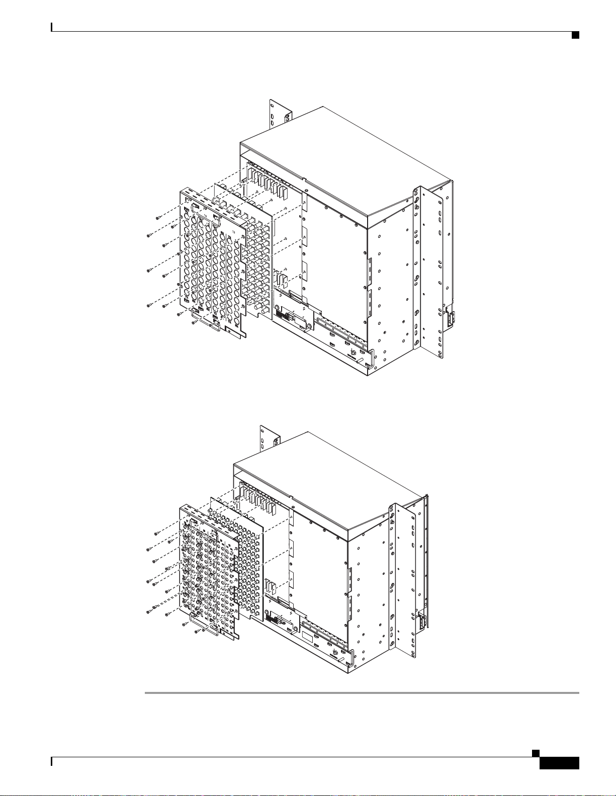
Chapter 1 Hardware Installation
Figure 1-17 Installing the High-Density BNC EIA
EIA Installation
1
2
1
3
2
1
4
3
2
5
6
7
8
9
10
11
12
1
4
3
2
5
4
3
6
5
4
7
6
5
8
7
6
9
8
7
10
9
8
11
10
9
12
11
10
12
11
12
Figure 1-18 Installing the SMB EIA (use a balun for DS-1 connections)
43766
November 2001
43762
Cisco ONS 15454 Installation and Operations Guide
1-23
Page 62

EIA Installation
Procedure: Install the AMP Champ EIA
Step 1 T o r em ove the lower backplane cover, loosen the five screws that se cu re it to the ONS 15454 and pull it
away from the shelf assembly.
Step 2 Align the AMP Champ cover panel with the backplane and insert and tighten the nine perimeter screws
(P/N 48-0358) a t 8 -10 lbs.
Step 3 Align an AMP Champ card with the backplane connector and push until it fits snugly. Repeat until you
have installed all six AMP Champ cards.
Step 4 To secure each AMP Champ card to the cover panel, insert and tighten a screw (P/N 48-0003) at the top
of each card at 8-10 lbs.
Step 5 Place the AMP Ch amp fa sten ing plat e a long the b otto m of the c over p anel, and ha nd tight en t he two
thumbscrews.
Figure 1-19 shows an AMP Champ EIA installation.
Figure 1-19 Installing the AMP CHAMP EIA
Chapter 1 Hardware Installation
1-24
44309
Cisco ONS 15454 Installation and Operations Guide
November 2001
Page 63

Chapter 1 Hardware Installation
1.7 Fan-Tray Assembly Installation
The fan-tray assembly is located at the bottom of the ONS 15454 front compartment. The fan tray is a
removable drawer th at holds fa ns and fan-c ontrol circuit ry for the ONS 15454 . The fro nt door can be
left in place when remov ing or installing the fan t ray but re moval is recommended. After you install the
fan tray, you should only need to access it if a fan failure occur s or you need to replace o r clean the
fan-tray air fil ter.
The front of the fan-tra y assembly h as an LCD scree n that pro vides slot an d port- level infor mati on for
all ONS 15454 card slots, including the number of Critical, Major, and Minor alarms.
The fan-tray assembly features an air filter at the bottom of the tray that you can install and remove by
hand. Remove and visually inspect this filter every 30 days and keep spare filters in stock. See the Cisco
ONS 15454 Troubleshooting and Maintenance Guide for information about cleaning and maintaining the
fan-tray air fil ter.
Note The 10-Gbps c ompatible shelf asse mbly (15454-SA-ANSI, P/N: 800-19857) and fan-tray assembly
(15454-FTA3) are require d with the ON S 1 545 4 XC10G , OC-1 92, an d O C-4 8 an y slo t (A S) c ar ds.
Fan-Tray Assembly Installation
Caution Do not operate an ONS 15454 without a fan-tray filter. A fan-tray filter is mandatory.
Caution The 15454-F TA3 fan-tray assembly can only be installed in ONS 15454 Release 3.1 shelf assemblies
(15454-SA-ANSI, 800 -19 857) . It inc lude s a p in th at does no t al low it to be insta lled in ON S 154 54
shelf assemblies released before ON S 15454 Rele ase 3.1 (154 54-SA-N EBS3E, 1545 4-SA-NE BS3,
and 15454-SA-R1, P/N 800-0714915454 ). Installing the 15454-FTA3 in a non-compl iant shelf
assembly may result in failure of the alarm in terf ace pa nel (AIP ), wh ich in turn , will result in powe r
loss to the fan-tray assembly.
Note The ONS 15454 Release 3.1 fan-tray assembly (15454-FTA3) is not I-temp. To obtain an I-temp fan
tray, install the 15454-FTA2 fan-tray assembly in an ONS 15454 Release 3.1 shelf assembly (P/N:
800-19857). However, do not install the ONS 154 54 Release 3.1 XC10G, OC-192, and OC-48 any
slot (AS) cards in the shelf assemb ly with the 15 454-FTA2 fan-tr ay assembly.
If one or more fans fail on the fan-tray assembly, replace the entire assembly. You cannot replace
individual fans. The r ed Fan Fail LED on the f ront of th e fan tray illuminates when one or mo re fans f ail.
For fan tray replacem en t instructions, see the “Install the Fan-Tray Assembly” procedure on page 1-27.
The red Fan Fail LED clears after you install a working fan tray.
Fan speed is contr oll ed by T CC+ c ard tem pera ture se nso rs. T he se nso rs me asu re the in put air
temperature at the fan-t ray a ssem bly. Fan speed optio ns are lo w, medium, and hi gh. I f the TCC+ car d
fails, the fans automatically shift to high speed. The temperature measured by the TCC+ sensors is
displayed on the LCD screen .
November 2001
Cisco ONS 15454 Installation and Operations Guide
1-25
Page 64

Fan-Tray Assembly Installation
Procedure: Install the Bottom Brackets and Air Filter
The shelf assembly ships with bottom brackets that you should use to install the air filter. The bottom
brackets consist of two grooved metal pieces that attach to the bottom of the shelf assembly using three
screws each. When you use the bottom bracket to install the fan-tray air filter, you do not need to remove
the fan-tray assembly to access the air filter. Attach the brackets to the bottom of the shelf assembly
before installing the rack.
Although the fi lter wi ll work i f i t is inst al led with e ither si de fa cin g u p, Cisc o re com mend s tha t y ou
install it with the metal bracing facing up to preserve the surface of the filter.
Note If you choose not to install the bottom brackets, install the air filter by sliding it into the compartment
at the bottom of the shelf ass embly. Each time you remove and reinsta ll the air fi lter in th e future ,
you must f ir st r em ov e th e fa n - tr a y a ss e mb ly.
Step 1 With the fan-tray assembly removed, pla ce the ONS 154 54 face down on a flat surfac e.
Step 2 Locate the three screw holes that run along the left and right sides of the bottom of the shelf assembly.
Step 3 Secure each bracket to th e bottom of th e shelf asse mbly usi ng the scre ws provid ed.
Each bracket has a filter stopper and a flange on one end. Make sure to attach the brackets with the
stoppers and flanges facing the rear of the shelf assembly (the top, if the ONS 15454 is face-down during
installation).
Chapter 1 Hardware Installation
Figure 1-20 illustrates bottom bracket installation. If you do not use the bottom brackets, in the future
you must remove the fan-tray assembly before removing the air filter. The bottom brackets enable you
to clean and replace the air filter without removing the fan-tray assembly.
Figure 1-20 Installing the bottom brackets
BAT 2
-42 TO -57 Vdc
650 Watts Maximum
RET 2
BAT 1
RET 1
SUITABLE FOR MOUNTING ON
A NON-COMBUSTIBLE SURFACE.
PLEASE REFER TO INSTALLATION
INSTRUCTIONS.
CAUTION: Remove power from both
the BAT1 and terminal blocks
prior to servicing
39487
1-26
If you are using the bottom brackets to install th e fan-tray air filte r , you ca n install thr ee shelf asse mblies
in a standard sev en -foot rac k. I f you are not usin g th e bott om bra cket s, yo u c an in stall four sh elf
assemblies in a rack.
Cisco ONS 15454 Installation and Operations Guide
November 2001
Page 65

Chapter 1 Hardware Installation
Step 4 Slide the air filter into the shelf assembly.
Procedure: Install the Fan-Tray Assembly
To install the fan-tray assembly, it is not necessary to move any of the cable-management facilities.
Caution You must place the edge of the air f ilter fl ush a gainst th e fro nt of t he fan-tray assem bly compar tment
when installing the fan tray on top of the filter. Failure to do so could result in damage to the filter,
the fan tray, or both.
Caution Do not force a fan-tray assembly into place. Doing so can damage the connectors on the fan tray
and/or the con ne ctor s o n th e ba ck pane l o f the she lf asse mb ly.
Step 1 Remove the front door of the shel f assembly.
Fan-Tray Assembly Installation
Step 2 Slide the fan tray into the shelf assembly until the electrical plug at the rear of the tray plugs into the
correspondin g r ec ept a cle on the ba ckp lan e.
Step 3 To verify that the tray has plugged into the backplane, check that the LCD on the front of the fan tray is
activated.
Figure 1-21 shows the locati on of the fan tr ay.
November 2001
Cisco ONS 15454 Installation and Operations Guide
1-27
Page 66
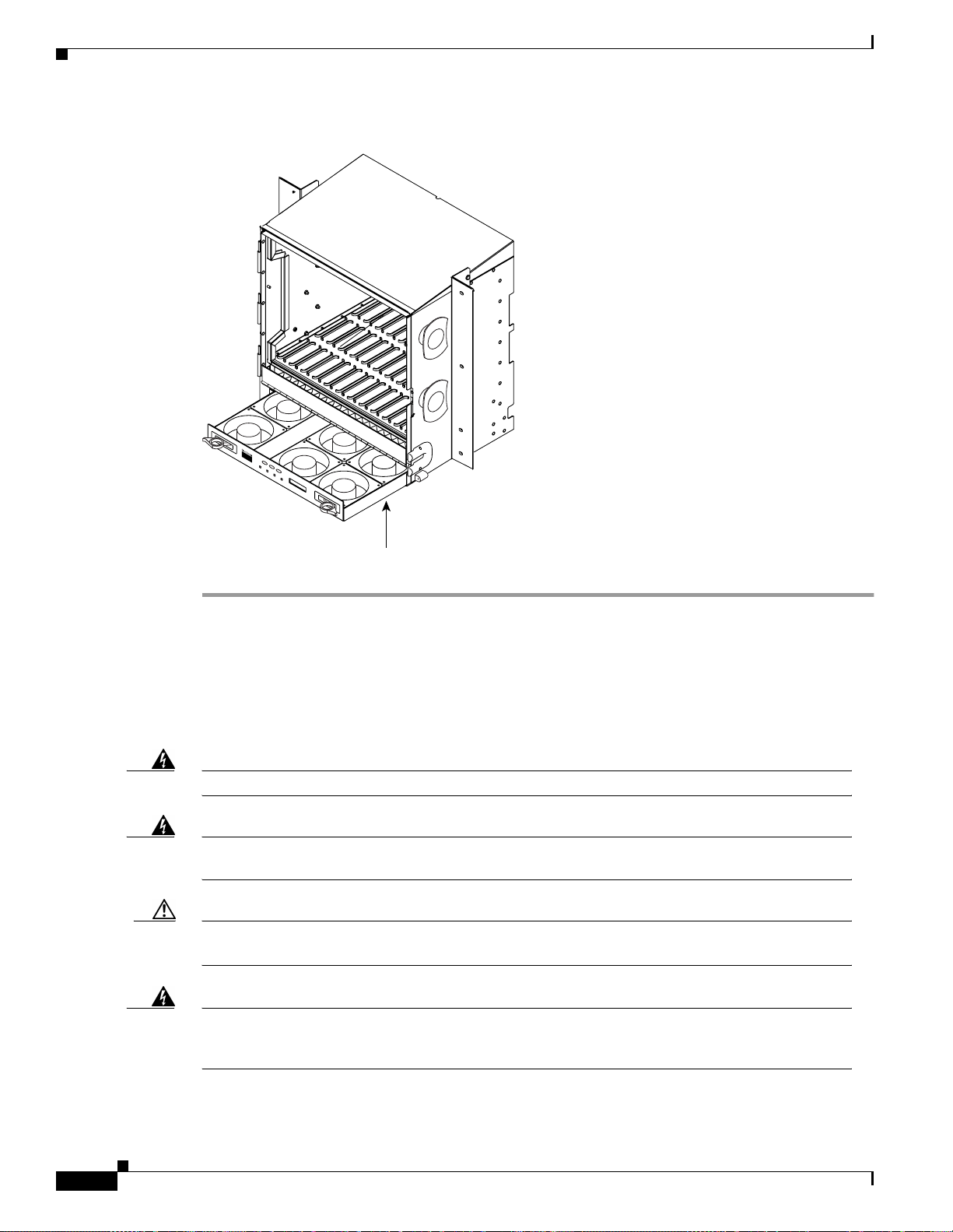
Power and Ground Installation
Figure 1-21 Installing the fan-tray assembly
Chapter 1 Hardware Installation
38532
F
A
N
F
A
IL
C
R
I
T
M
A
J
M
I
N
Fan tray
assembly
1.8 Power and Ground Installation
This section expla ins how t o conn ec t the ONS 154 54 asse mbl y to the p ower suppl y. Ground the
equipment accor ding t o Telcordia standards o r lo cal p ra ctic es.
Warning
Warning
Caution Always use the supplied ESD wristband when working with a powered ONS 15454. Plug th e
Shut off the power from the power source or turn off the breakers before beginning work.
This equipment is intended to be grounded. Ensure that the host is connected to earth ground
during normal use.
wristband cable into the ESD jack located on the lower-right outside edge of the shelf assembly.
1-28
Warning
Do not mix conductors of dissimilar metals in a terminal or splicing connector where physical
contact occurs (such as copper and aluminum, or copper and copper-clad aluminum), unless the
device is suited for the purpose and conditions of use.
Cisco ONS 15454 Installation and Operations Guide
November 2001
Page 67

Chapter 1 Hardware Installation
Power and Ground Installation
Warning
Warning
Warning
Connect the ONS 15454 only to a DC power source that complies with the safety extra-low voltage
(SELV) requirements in IEC 60950-based safety standards.
The ONS 15454 relies on the protective devices in the building installation to protect against short
circuit, overcurrent, and grounding faults. Ensure that the protective devices are properly rated to
protect the system, and that they comply with national and local codes.
A readily accessible two-poled disconnect device must be incorporated in the fixed wiring.
Cisco recommends the fol lowing w iring conve ntion s, but cus tomer co nventions prevai l:
• Red wire for bat tery co nne ctio ns ( -48V DC )
• Black wire for battery return connections (0V DC)
The ONS 15454 has redundan t -48V DC #8 po wer termina ls on the shel f assembl y backplane . The
terminals are labeled BAT1, RET1, BAT2, and RET2 and are loc ated on the low er sectio n of the
backplane behi nd a c l ear pla st ic co ver. See the “Lower Backplane Cover” section on page 1-15 for
information about acc essing th e power t erminal s.
To install redundant power feeds, use four power cables and one ground cable. For a single power feed,
only two power c abl es (#10 AWG, copper conduc tor, 194°F [90°C]) and one ground ca ble (#6 AWG)
are required. Use a conductor with low impedance to ensure circuit overcurrent protection. However, the
conductor must have the capability to safely conduct any fault current that might be imposed.
Warning
Warning
The existing ground post is a #10-32 bolt. The nut provided for a field connection is also a #10, with an
integral lock washer. The lug must be a dual-h ole ty pe an d rate d to ac cept the # 6 AWG cable. Two posts
are provided on the Cisco ONS 15454 to accommodate the dual-hole lug. Figure 1-22 shows the location
of the ground posts.
Figure 1-22 Ground posts on the ONS 15454 backplane
FRAME GROUND
61852
For information about attaching ferrites to power cabling, see the “Ferrite Installation” section on
page 1-61.
When installing redundant power feeds, do not use aluminum conductors.
If you use redundant power leads to power the ONS 15454, disconnecting one lead will not remove
power from the node.
November 2001
Cisco ONS 15454 Installation and Operations Guide
1-29
Page 68

Power and Ground Installation
Procedure: Install Redundant Power Feeds
Ground only one ca ble to gr ound t he she lf a ssemb ly. Terminate the other end of t h e gro und c abl e t o
ground according to loc al s ite p racti ce. T he O NS 1 5454 b ac kp lane al so ha s a g round t ermin al on t h e
right side of the backplane. Connect a ground terminal for the frame ground (FGND) terminal according
to local site practice.
If the system lose s pow er or both T CC+ c ards ar e rese t, y ou mu st rese t the ON S 1 545 4 cl ock. Aft er
powering down, the da te de fault s to Ja nu ary 1 , 197 0, 00 :0 4:15. To reset the clock, see t he “Setting Up
Basic Node Informat ion” section on page 3-2.
Note If you encounter problems with the power supply, refer to the Cisco ONS 15454 Tr oubleshooting and
Maintenance Guide for possible causes.
Chapter 1 Hardware Installation
Warning
Do not apply power to the ONS 15454 until you complete all installation steps and check the
continuity of the -48V DC and return.
Step 1 Measure and cut the cables as need ed to re ach the ON S 15454 from the fuse pa nel. Figu re 1 -23 sho ws
the ONS 15454 po wer te rmin al s.
Step 2 Dress the power and ground cables according to local site practice.
Warning
When installing the ONS 15454, the ground connection must always be made first and
disconnected last.
Figure 1-23 Power terminals
Return leads (black)
Battery leads (red)
RET 1
BAT 1 RET 2 BAT 2
1-30
CAUTION: Remove power from both
the BAT1 and terminal blocks
prior to servicing
Cisco ONS 15454 Installation and Operations Guide
-42 V 24 A
SUITABLE FOR MOUNTING ON
A NON-COMBUSTIBLE SURFACE.
PLEASE REFER TO INSTALLATION
INSTRUCTIONS.
33921
November 2001
Page 69

Chapter 1 Hardware Installation
Step 3 Remove or loosen the #8 power terminal screws on the ONS 15454. T o avoid confusion, label the cables
connected to the BAT1/RET1 power terminals as 1, and the cab les connected to the BAT2/RET2 powe r
terminals as 2.
Note Use only press ure t erm i nal co nnec tors, su ch as ri ng and f or k ty pes, wh en t ermi nat ing the
Caution Before you make any crimp connections, coat all bare conductors (battery, battery return, and
Caution When terminating power, return, and frame ground, do not use soldering lug, screwless
Power and Ground Installation
battery, battery return, and f ra me g rou nd condu ct ors.
frame ground) w it h an a ppr opr iate ant ioxi dant co mpo und . Bring a ll un pl ate d conne c tors,
braided strap, and bus bars to a bright finish, then coat with an antioxidant before you connect
them. You do not need to prep are tin ned , sold er plat ed, or si lve r-plated c onn ect or s and othe r
plated connection surfaces, but always keep them clean and free of contaminants.
(push-in) con nect or s, quic k-con ne ct, or o ther f ric tion -fi t co nne ct ors.
Step 4 Strip 1/2 inch of insulation from all power cables that you will use. Crimp the lugs onto the ends of all
power leads.
Note When terminating battery and battery retu rn conne ctions as show n in Figure 1-23, follow a
torque specification of 10 in-lbs. When terminating a frame ground, use the kep-nut provided
with the ONS 15454 and tighten it to a torque specifica tion of 31 in-lbs. The kep-nut provid es
a frame ground connect ion that minimiz es the possibi lity of loo sening ca used by rota tion
during installation and maintenance activity. This type of prevention is inherently provided
by the terminal block for battery an d batte ry return connect ions.
Step 5 Terminate the return 1 lead to the RET1 backplane terminal. Use oxidation-prevention grease to keep
connections non- co rrosi ve.
Warning
Step 6 T erminate the neg ative 1 lead to the nega tive BAT1 backplane power ter minal. Use oxidation prevention
Do not secure multiple connectors with the same bolt assembly.
grease to keep conn ec tions non -c orrosi ve.
Step 7 If you use redundant power leads, ter minate the return 2 lead to the positive RET2 terminal on the ONS
15454. Terminate the negative 2 l e ad t o the nega t ive BAT2 terminal on the ONS 1 5454 . U se
oxidation-prevent at ive grea se to ke ep c on ne ctions no n-cor rosi ve.
Route the cables out below the power terminals using the plastic cable clamp.
November 2001
Cisco ONS 15454 Installation and Operations Guide
1-31
Page 70

Chapter 1 Hardware Installation
Alarm, Timing, LAN, and Craft Pin Connections
1.9 Alarm, Timing, LAN, and Craft Pin Connections
Caution Always use the supplied ESD wristband when working with a powered ONS 15454. Plug th e
wristband cable into the ESD jack located on the lower-right outside edge of the shelf assembly.
The ONS 15454 h as a backp lane pi n field lo cated at t he bottom of the backplan e. The back plane pi n field
provides 0.045 squa re inch w ire -wra p pins fo r ena bli ng e xte rna l a lar ms, t iming i np ut a nd ou t put, and
craft interface terminals. This section describes the backplane pin field and the pin assignments for the
field. Figure 1-24 shows the wire-wrap pins on the backplane pin field. Beneath each wire-wrap pin is a
frame ground pin. Frame grou nd pins ar e labeled FG1 , FG2, FG3, etc . Install the ground shield of the
cables connect ed t o the ba ck plan e to t he groun d p in tha t co rr esp onds t o the p in fi e ld u sed . Fi gure 1-24
shows pinouts for the ON S 1 5454 .
Figure 1-24 Pinouts
BITS LAN
FG1
OUTIN
LOCAL ALARMSCRAFTMODEM X . 25 ACO ENVIR ALARMS
ABABAABABABABABABABA B
111111111111
2222222222
3333333333
4444444444
2
3
4
AUDVIS
2
TBOS
FG12FG11FG10FG9FG8FG7FG6FG5FG4FG3FG2
Field Pin Function Field Pin Function
BITS A1 BITS Output 2 negative (-)
B1 BITS Output 2 positive (+) B1
A2 BITS Input 2 negative (-) A2 Normally open output pair number 2
B2 BITS Input 2 positive (+) B2
A3 BITS Output 1 negative (-) A3 Normally open output pair number 3
B3 BITS Output 1 positive (+) B3
A4 BITS Input 1 negative (-) A4 Normally open output pair number 4
B4 BITS Input 1 positive (+) B4
LAN 1 Connecting to a Router, Hub, or Switch ACO A1 Normally open ACO pair
LAN 2
ENVIR
ALARMS
IN
RJ-45 pin 6
A1 B1
RJ-45 pin 3
B1 CRAFT A1 Receive (PC pin #2)
RJ-45 pin 2
A2 A2 Transmit (PC pin #3)
B2 A3 Ground (PC pin #5)
RJ-45 pin 1
Connecting to a PC or Workstation
A1
RJ-45 pin 2
RJ-45 pin 1
B1 B1
A2
RJ-45 pin 6
A2 Alarm output pair number 2: Critical
RJ-45 pin 3
B2
A3 Alarm output pair number 3: Major
Not Used
A1 B3
Alarm input pair number 1: Reports
closure on connected wires.
B1 A4 Alarm output pair number 4: Minor
A2 B4
Alarm input pair number 2: Reports
closure on connected wires.
B2
A3 B1
Alarm input pair number 3: Reports
closure on connected wires.
B3
A4
Alarm input pair number 4: Reports
closure on connected wires.
B4
ENVIR
ALARMS
LOCAL
ALARMS
(Audible)
LOCAL
ALARMS
(Visual)
A1 Normally open output pair number 1
OUT
N/O
A4 DTR (PC pin #4)
A1 Alarm output pair number 1: Remote
AUD
N/O
VIS
N/O
audible alarm.
audible alarm.
B2
audible alarm.
audible alarm.
A1 Alarm output pair number 1: Remote
visual alarm.
A2 Alarm output pair number 2: Critical
visual alarm.
B2
A3 Alarm output pair number 3: Major
visual alarm.
B3
A4 Alarm output pair number 4: Minor
visual alarm.
B4
38533
1-32
Cisco ONS 15454 Installation and Operations Guide
November 2001
Page 71

Chapter 1 Hardware Installation
Note The X.25, Modem, and TB OS pin fie lds are not active.
1.9.1 Alarm Installation
The alarm pin field supports up to 17 al arm contacts, includi n g four audible alarms, four visual alarms,
one alarm cu toff (A CO ) , and four u s er-def inab l e al a rm inp ut a nd ou tp ut c on t act s.
Audible alarm contacts are in the LOCAL ALARM AUD pin field and visual contacts are in the LOCAL
ALARM VIS pin field. Both of these alarms are in the LOCAL ALARMS category. User-definable
contacts ar e in t he EN V IR A LARM I N and EN V IR AL AR M O UT p i n f iel ds. T he se al ar ms ar e in t h e
ENVIR ALARMS category; you must have the A IC card installed to use the E NVIR ALARMS. Alarm
contacts are N ormal ly O pen (N /O) , mean ing th at th e syst em cl oses the alarm co ntac ts whe n the
correspondin g a la rm c ond iti on s a re p re sen t . Ea ch a lar m co ntac t co n sis ts of t wo wi r e-wr ap p in s o n t h e
shelf assembly backplane. Visual and audible alarm contacts are c lassified as Critic al, Major , Minor , and
Remote. Figure 1-24 shows alarm pin assignm ents.
Vi sual an d audi ble ala rms are ty pically wired to trigger an alarm lig ht at a ce ntra l alarm collect ion p oint
when the correspondi ng contacts are cl osed. You can use the Alarm Cutof f pins to activ ate a remote ACO
for audible alarms . You can also activate the ACO function by pressing the ACO but ton on the TCC+
card faceplate. The ACO function clears all audible alarm indications. After clearing the audible alarm
indication, the alarm is still present and viewable in the Alarms tab in CTC.
Alarm, Timing, LAN, and Craft Pin Connections
Procedure: Install Alarm Wires on the Backplane
Step 1 Use #22 or #24 AWG alarm wires.
Step 2 Wrap the alarm wires on the appropriat e wire-w rap pins acc ording t o local site pr actice .
Note For information about attaching ferrites to wire-wrap pin fields, see the “Ferrite Installation”
section on page 1-61.
1.9.2 Timing Installation
The ONS 15454 backplane supports two Building Integrated Timing Supply (BITS) clock pin fields. The
first four BITS pins, ro ws 3 and 4, support output and input fr om the first external timing dev ice. Th e
last four BITS pins, rows 1 and 2, perform the identical functions for the second external timing device.
Table 1-2 lists the pin assignments for the BITS timing pin fields.
November 2001
Cisco ONS 15454 Installation and Operations Guide
1-33
Page 72

Alarm, Timing, LAN, and Craft Pin Connections
Table 1-2 External Timing Pin Assignments for BITS
External Device Contact Tip & Ring Function
First external device A3 (BITS 1 Out) Primary ring (-) Output to external device
Second external device A1 (BITS 2 Ou t) Primary ring (-) Output to external device
Chapter 1 Hardware Installation
B3 (BITS 1 Out) Primary tip (+) Output to external device
A4 (BITS 1 In) Secondary ring (-) Input from external
device
B4 (BITS 1 In) Secondary tip (+) Input f rom ext erna l
device
B1 (BITS 2 Out) Primary tip (+) Output to external device
A2 (BITS 2 In) Secondary ring (-) Input from external
device
B2 (BITS 2 In Secon da ry t ip ( +) Inp ut f rom ext erna l
device
Note Refer to Telcordia SR-NWT-002224 for rules about provisi oning ti ming ref eren ces
Procedure: Install Timing Wires on the Backplane
Step 1 Use #22 or #24 AWG wire.
Step 2 Wrap the clock wires on the appropriate wire-wrap pins according to local site practice.
Step 3 The BITS pin field (FG1) has a frame ground pin beneath it. Wrap the ground shield of t he alarm cable
to the frame ground pin .
Note For more detailed information about timing, see the “Setting Up ONS 15454 Timing” section
on page 3-12.
1.9.3 LAN Installation
Use the LAN pins on the ONS 15454 backplane to connect the ONS 15454 to a workstation or Ethernet
LAN, or to a LAN modem for re mote ac cess to the nod e. You can also use the LAN port on the TCC+
faceplate to connect a workstation or to connect the ONS 15454 to the network. Table 1-3 shows the
LAN pin assignments.
1-34
Before you can connect an ONS 15454 to other ONS 15454s or to a LAN , you must chan ge the default
IP address that is shi p ped w ith ea ch O NS 1 545 4 (192 .1 .0. 2). See the “Change IP Addr es s, Defa ult
Router, and Network Mask Using the LCD” procedure on page 3-4 .
Cisco ONS 15454 Installation and Operations Guide
November 2001
Page 73

Chapter 1 Hardware Installation
Table 1-3 LAN Pin Assignments
Pin Field Backplane Pins RJ-45 Pins
LAN 1
Connecting to data
circuit-terminating
equipment (DCE*) (a
hub or switch)
LAN 1
Connecting to data
terminal equipment
(DTE) (a
PC/workstation or
router)
*The Cisco ONS 15454 is DCE.
Alarm, Timing, LAN, and Craft Pin Connections
B2 1
A2 2
B1 3
A1 6
B1 1
A1 2
B2 3
A2 6
Procedure: Install LAN Wires on the Backplane
Step 1 Use #22 or #24 AWG wire.
Step 2 Wrap the wires on the appropriate wire-wrap pins according to local site practice.
Step 3 A frame ground pin is located beneath each pin field (FG2 for the LAN pin field). Wrap the ground shield
of the LAN interface cable to the frame ground pin.
1.9.4 TL1 Craft Interface Installation
You ca n u se t he c raft pins on t he O NS 15 454 ba c kpla ne o r th e RS-2 32 port on the TCC+ face pla te to
create a VT100 e mula t ion win dow to serv e as a TL1 c raft int erf ac e t o the ON S 15 454 . Us e a
straight-through cabl e to conne ct to the RS- 232 port. Table 1-4 shows the pin a ssignmen ts for the
CRAFT p i n fi eld.
Note You ca nnot use t h e cr af t ba ckpl ane pin s a nd t he RS- 232 p ort on the TCC+ car d simult ane ously.
Table 1-4 Craft Interface Pin Assignments
Pin Field Contact Function
Craft A1 Receive
A2 Transmit
A3 Ground
A4 DTR
November 2001
Cisco ONS 15454 Installation and Operations Guide
1-35
Page 74

Coaxial Cable Installation
Procedure: Install Craft Interface Wires on the Backplane
Step 1 Use #22 or #24 AWG wire.
Step 2 Wrap the craft interface wires on the appropriate wire-wrap pins accordin g to local site practice.
Note For information about attaching ferrites to wire-wrap pin fields, see the “Ferrite Installation”
section on page 1-61.
Step 3 Wrap the ground shield of the craft interface cable to the frame-ground pin.
Step 4 Wrap the ground wire o f your com pu ter cab le t o pin A3 on th e c raft p in f iel d.
1.10 Coaxial Cable Installation
Chapter 1 Hardware Installation
Caution Always use the supplied ESD wristband when working with a powered ONS 15454. Plug th e
wristband cable into the ESD jack located on the lower-right outside edge of the shelf assembly.
When using ONS 15454 D S-3 e lec tri cal cabl es , t he cab les mus t ter mina t e on a n E IA in stall e d on th e
ONS 15454 backplane. EIAs are available with SMB and BNC connectors. All DS-3 cables connected
to the ONS 15454 DS-3 card must terminate with coaxial cables using the desired connector type to
connect to the specif ied EIA. For information about physically installing an EIA in the field, see the
“Install a BNC, High-Density BNC, or SMB EIA” procedure on page 1-22. For information about
coaxial cable management, see the “Coaxial C able Ma nage ment ” section on page 1-57.
The electromagnetic compatibility (EMC) performance of the system depends on good-quality DS-3
coaxial cables, such as Shun er Type G 03233 D, or the equivalent.
1.10.1 BNC Connector Installation
For a description of BNC EI As, se e the “BNC EIA” sectio n on page 1- 17. The BNC conne ctors on the
EIA supports Trompeter U CB J224 (7 5 Ohm) 4 leg conn ect ors . Right-a ng le mat ing c on nect ors fo r t he
connecting cable are AMP 413588-2 (75 Ohm) conn ector s. If pref erre d, you can also use a straight
connector of the same type. Use RG-59/U cable to connect to the ONS 15454 BNC EIA. These cables
are recommende d to c on nect to a p atch p an el an d are desig ne d for l on g runs of up to 450 f eet .
Procedure: Install Coaxial Cable With BNC Connectors
1-36
Step 1 Place the B NC c able co nnect o r o ve r th e de si re d co nne ct ion p oi nt o n th e ba ck plan e.
Figure 1-25 shows how to connect a coaxial cable to the BNC EIA using a right-angle BNC cable
connector.
Step 2 Position the cab le co nne cto r s o t hat th e slot in t he c onn ect or is ov er t he co rr esp ondin g n ot ch a t t he
backplane connec tion poi nt.
Cisco ONS 15454 Installation and Operations Guide
November 2001
Page 75

Chapter 1 Hardware Installation
Step 3 Gently push the conne ctor dow n until th e notch ba ckplan e conne ctor sl ides into th e slot on th e cable
connector.
Step 4 Turn the cable connector until the notch clicks into place.
Step 5 Tie wrap or lace th e cabl es to the E IA ac co rdin g to Telcordia standa rds (GR- 127 5-C OR E) or l oc al site
practice.
Step 6 Route the cables to the neare st side of the shelf a ssembly thr ough the side c utouts acco rding to lo cal site
practice. The rubber coated edges of the side cutouts prevent the cables from chafing.
Figure 1-25 Using a right-angle connector to install coaxial cable with BNC connectors
Coaxial Cable Installation
32075
Note Slots 1, 3, 15 and 17 are designated protection slots when BNC connectors are used. Slots 5,
6, 11, and 12 do not support DS3-12 cards when BNC connec tors are used. A total of four
DS3-12 cards can be used to carry tra ffic with BNC conn ectors.
Step 7 Label all cables at each end of the connection to avoid confusion with cables that are similar in
appearance .
1.10.2 High-Density BNC Connector Installation
The High-Density BNC EIA supp orts Trompeter UCBJ224 (75 Ohm) 4 leg co nnectors. Use straigh t
connectors on RG-59/U ca ble to connect to the Hig h-Density BNC EIA. Cisco recommends th ese cables
for connection to a pat ch pane l; the y are de signe d for l on g runs of u p t o 45 0 fe et. For m ore deta il , see
the “High-Density BNC EIA” section on page 1-18.
Although not required, Cisco strongly recommends using the BNC insertion tool to connect cables to the
EIA. Refer to the Cisco ONS 15454 Tr oubleshooting and Maintenance Guide for more information about
the insertion tool.
November 2001
Cisco ONS 15454 Installation and Operations Guide
1-37
Page 76

Coaxial Cable Installation
Procedure: Install Coaxial Cable With High-Density BNC Connectors
Step 1 Place the B NC c able co nnect o r o ve r th e de si re d co nne ct ion p oi nt o n th e ba ck plan e.
Step 2 Using the insertions tool, position the cable connec tor so that the slot in the connector is over the
corresponding n ot ch a t t he ba ckp lan e co nnec tio n p oin t.
Step 3 Gently push the connecto r down until the notch backplane co nnector slides into the slot on the cable
connector.
Step 4 Turn the cable connector until the notch clicks into place.
Step 5 Tie wrap or lace th e cabl es to the E IA ac co rdin g to Telcordia standa rds (GR- 127 5-C OR E) or l oc al site
practice.
Step 6 Route the cables to the neare st side of the shelf a ssembly thr ough the side c utouts acco rding to lo cal site
practice.
The rubber coate d edges of the sid e cutout s prevent the cabl es fro m chaf ing.
Chapter 1 Hardware Installation
1.10.3 SMB Connector Installation
The SMB backplane cover is similar to the BNC cover. For further detail, see the “SMB EIA” section
on page 1-19. The SMB conn ectors on the EIA are A MP 415504-3 (7 5 Ohm) 4 leg c onnectors.
Right-angle mating co nnectors for the conne cting cable are A MP 41548 4-2 (75 Ohm) connect ors. Use
RG-179/U cable to connect to the ONS 15454 EIA. Cisc o recommends these cabl es for connection to a
patch panel; they are not de signed for long runs (over 50 feet) . Range doe s not affect loopb ack testi ng.
For information about attaching ferrites to SMB/BNC connectors, see the “Ferrite Installation” section
on page 1-61.
Procedure: Install Coaxial Cable with SMB Connectors
Refer to Figure 1-26 whe n perfo rm ing t h e follow ing ste ps.
Step 1 Place the SMB cable connector over the desired connection point on the backplane.
Step 2 Gently push the connector until it clicks into place.
Step 3 Tie wrap or lace th e cabl es to the E IA ac co rdin g to Telcordia standa rds (GR- 127 5-C OR E) or l oc al site
practice.
Step 4 Route the cables to the nearest side of the shelf assembly into rack runs according to local site practice.
1-38
Cisco ONS 15454 Installation and Operations Guide
November 2001
Page 77

Chapter 1 Hardware Installation
32100
Figure 1-26 Installing coaxial cable with SMB connectors
DS-1 Cable Installation
Warning
Step 5 Label the transm it, recei ve, working, and pr otect cables at each end of the conn ection to avoid confusio n
Metallic interfaces for connection to outside plant lines (such as T1/E1/T3/E3, etc.) must be
connected through a registered or approved device such as CSU/DSU or NT1.
with cables th at are similar in appearance.
1.11 DS-1 Cable Installation
DS-1s support both twisted pai r wire-wrap cabling an d AMP Champ co nnector ca bling . Install the
proper backplan e EI A on the O NS 1545 4 for eac h c ab ling o ption. T his sec tio n prov i des inf orm ation
about the DS-1 EIA opt ions.
For information a bout DS-1 cab le manage ment, see the “DS-1 T wisted-Pair Cable Management” section
on page 1-58.
1.11.1 Twisted Pair Wire-Wrap Installation
Installing twisted-p air, wire-wrap DS-1 cable s require s separate pairs of grou nded twiste d-pair c ables
for receive (in) and transmit (out). Prepare four cables, two for receive and two for transmit, for each
DS-1 facility to be installed.
November 2001
Cisco ONS 15454 Installation and Operations Guide
1-39
Page 78

DS-1 Cable Installation
Caution Always use the supplied ESD wristband when working with a powered ONS 15454. Plug th e
Note DS-1 electrical interface adapters project an additional 1.72 inches from the ONS 15454 backplane.
Chapter 1 Hardware Installation
wristband cable into the ESD jack located on the lower-right outside edge of the shelf assembly.
If you use DS-1 el ect ric al t wis ted -pai r ca ble s, e qu ip th e O NS 15 454 w ith an SM B E IA o n ea ch side of
the backplane where DS-1 cables will terminate. You must install special DS-1 electrical interface
adapters, comm only re ferred to as a bal un, on ev ery tran smit and receiv e conne cto r for each D S-1
termination.
If you install DS-1 cards in the O NS 15454, you mu st fit the co rrespo nding tran smit and re ceive SMB
connectors on the EIA with a DS-1 electrical interface adapter. You can install the adapter on the SMB
connector for the port. The adaptor has wire-wrap posts for DS-1 transmit and receive cables.
Figure 1-27 shows the DS-1 electrical interface adapter.
Figure 1-27 DS-1 electrical interface adapter (balun)
SMB Connector
DS-1
Electrical
interface
adapter
Wire wrap posts
Ring
Tip
32071
Each DS-1 electrical interface adapter has a female SMB connector on one end and a pair of .045 inch
square wire-wrap posts on th e other en d. The wire -wrap posts are .200 inc hes apart .
Procedure: Install DS-1 Cables Using Electrical Interface Adapters (Balun)
All DS-1 cables connected to the ONS 15454 DS-1 ports must terminate with twisted-pair cables to
connect to the DS-1 electrical interface adapter. The DS-1 electrical interface adapters project 1.72
inches beyond the SM B EIA.
Step 1 Attach the SMB connector on the adapter to the SMB connector for the port’s transm it pair on the
backplane.
1-40
Step 2 Attach the SMB connector on an adapter to the SMB connector for the port’s receive pair on the
backplane.
Step 3 Ter minate the DS-1 transmit and receive cables for the port to the wire-wrap posts on the adapter:
a. Using a wire-wrap tool, connect the receive cables to the receive adapter pins on the backplane
connector for the desired port.
b. Connect the transmit cables to the transmit adapter pins on the backplane connector for the desired
port.
Cisco ONS 15454 Installation and Operations Guide
November 2001
Page 79

Chapter 1 Hardware Installation
c. Terminate the shi el d gro und w ire on the DS -1 c a ble to gro und acc or ding t o loca l sit e pra cti ce.
If you put DS1N- 14 ca r ds in Slots 3 a nd 15 t o form 1:N p rote ction grou ps, do no t wi re Sl ots 3 and 15
for DS-1 electrical interface adapters.
Figure 1-28 shows a ONS 15454 backplane with an SMB EIA with DS-1 electrical interface adapters
attached on both sides of the shelf assembly to create DS-1 twisted-pair termination points.
Figure 1-28 A backplane with SMB EIA for DS-1 cables
DS-1 Cable Installation
DS-1 Electrical Interface
Adapter or balun
32085
1.11.2 AMP Champ Connector Installation
To install AMP Champ conne ctor DS- 1 cables , you must use 64- pin bundl ed cable co nnec tors with a
64-pin male AMP Champ conn ector. You need an AMP Champ connector #5522 7 6-1 fo r th e re cep ta cle
side and #1-552496-1 (for cable diam eter .4 75in.–.540in) or #2-552496 -1 (for cab le diam eter
.540in.–.605 in.) fo r the righ t-a ngle sh ell housi n g (or t hei r func ti onal equ iv alent ). T he cor re spon ding
64-pin female AMP Champ connector on the AMP Champ EIA supports one receive and one transmit
for each DS-1 port for the corresponding card slot.
Because each DS1-14 car d supports 14 DS- 1 ports, o nly 56 pins (28 pai rs) of the 64- pin conne ctor ar e
used. Prepare one 56-wire cable for each DS-1 facility installed. Table 1-5 shows the pin assignments
for the AMP Champ connector s on the ONS 1545 4 AMP Champ E IA. See the “AMP Champ EIA”
section on page 1-20 for more information about the AMP Champ EIA.
Table 1-5 Pin Assignments for AMP Champ Connectors (Shaded Area Corresponds to White/Orange
Binder Group)
Signal/Wire Pin Pin Signal/Wire Signal/Wire Pin Pin Signal/Wire
Tx Tip 1
white/blue
Tx Tip 2
white/orange
1 33 Tx Ring 1
blue/white
2 34 Tx Ring 2
orange/white
Rx Tip 1
yellow/orange
Rx Tip 2
yellow/green
17 4 9 Rx Ring 1
orange/yellow
18 5 0 Rx Ring 2
green/yellow
November 2001
Cisco ONS 15454 Installation and Operations Guide
1-41
Page 80

DS-1 Cable Installation
Chapter 1 Hardware Installation
Table 1-5 Pin Assignments for AMP Champ Connectors (Shaded Area Corresponds to White/Orange
Binder Group) (continued)
Signal/Wire Pin Pin Signal/Wire Signal/Wire Pin Pin Signal/Wire
Tx Tip 3
white/green
Tx Tip 4
white/brown
Tx Tip 5
white/slate
Tx Tip 6
red/blue
Tx Tip 7
red/orange
Tx Tip 8
red/green
Tx Tip 9
red/brown
Tx Tip 10
red/slate
Tx Tip 11
black/blue
Tx Tip 12
black/orange
Tx Tip 13
black/green
Tx Tip 14
black/brown
3 35 Tx Ring 3
green/white
4 36 Tx Ring 4
brown/white
5 37 Tx Ring 5
slate/white
6 38 Tx Ring 6
blue/red
7 39 Tx Ring 7
orange/red
8 40 Tx Ring 8
green/red
9 41 Tx Ring 9
brown/red
10 42 Tx Ring 10
slate/red
11 43 Tx Ring 1 1
blue/black
12 44 Tx Ring 12
orange/black
13 45 Tx Ring 13
green/black
14 46 Tx Ring 14
brown/black
Rx Tip 3
yellow/brown
Rx Tip 4
yellow/slate
Rx Tip 5
violet/blue
Rx Tip 6
violet/orange
Rx Tip 7
violet/green
Rx Tip 8
violet/brown
Rx Tip 9
violet/slate
Rx Tip 10
white/blue
Rx Tip 11
white/orange
Rx Tip 12
white/green
Rx Tip 13
white/brown
Rx Tip 14
white/slate
19 5 1 Rx Ring 3
brown/yellow
20 5 2 Rx Ring 4
slate/yellow
21 5 3 Rx Ring 5
blue/violet
22 5 4 Rx Ring 6
orange/violet
23 5 5 Rx Ring 7
green/violet
24 5 6 Rx Ring 8
brown/violet
25 5 7 Rx Ring 9
slate/violet
26 58 Rx Ring 10
blue/white
27 59 Rx Ring 11
orange/white
28 60 Rx Ring 12
green/white
29 61 Rx Ring 13
brown/white
30 62 Rx Ring 14
slate/white
Tx Spare0+ N/ A 15 47 Tx Spare0- N/A Rx Spar e0 + N /A 31 63 Rx Spare0- N/A
Tx Spare1+ N/ A 16 48 Tx Spare1- N/A Rx Spar e1 + N /A 32 64 Rx Spare1- N/A
1-42
Table 1-6 shows the pin assignme nts for the AMP Cham p connecto rs on the ONS 15 454 AMP Champ
EIA for a shield ed DS1 ca ble.
Table 1-6 Pin Assignments for AMP Champ Connectors (shielded DS1 cable)
64-Pin Blue Bundle 64-Pin Orange Bundle
Signal/Wire Pin Pin Signal/Wire Signal/Wire Pin Pin Signal/Wire
Tx Tip 1
1 33 Tx Ring 1
white/blue
Tx Tip 2
2 34 Tx Ring 2
white/orange
Tx Tip 3
3 35 Tx Ring 3
white/green
Tx Tip 4
4 36 Tx Ring 4
white/brown
Cisco ONS 15454 Installation and Operations Guide
blue/white
orange/white
green/white
brown/white
Rx Tip 1
white/blue
Rx Tip 2
white/orange
Rx Tip 3
white/green
Rx Tip 4
white/brown
17 4 9 Rx Ring 1
blue/white
18 5 0 Rx Ring 2
orange/white
19 5 1 Rx Ring 3
green/white
20 5 2 Rx Ring 4
brown/white
November 2001
Page 81

Chapter 1 Hardware Installation
Table 1-6 Pin Assignments for AMP Champ Connectors (shielded DS1 cable) (continued)
64-Pin Blue Bundle 64-Pin Orange Bundle
Signal/Wire Pin Pin Signal/Wire Signal/Wire Pin Pin Signal/Wire
Tx Tip 5
white/slate
Tx Tip 6
red/blue
Tx Tip 7
red/orange
Tx Tip 8
red/green
Tx Tip 9
red/brown
Tx Tip 10
red/slate
Tx Tip 11
black/blue
Tx Tip 12
black/orange
Tx Tip 13
black/green
Tx Tip 14
black/brown
Tx Tip 15
black/slate
Tx Tip 16
yellow/blue
5 37 Tx Ring 5
slate/white
6 38 Tx Ring 6
blue/red
7 39 Tx Ring 7
orange/red
8 40 Tx Ring 8
green/red
9 41 Tx Ring 9
brown/red
10 42 Tx Ring 10
slate/red
11 43 Tx Ring 1 1
blue/black
12 44 Tx Ring 12
orange/black
13 45 Tx Ring 13
green/black
14 46 Tx Ring 14
brown/black
15 47 Tx Tip 15
slate/black
16 48 Tx Tip 16
blue/yellow
Rx Tip 5
white/slate
Rx Tip 6
red/blue
Rx Tip 7
red/orange
Rx Tip 8
red/green
Rx Tip 9
red/brown
Rx Tip 10
red/slate
Rx Tip 11
black/blue
Rx Tip 12
black/orange
Rx Tip 13
black/green
Rx Tip 14
black/brown
Rx Tip 15
black/slate
Rx Tip 16
yellow/blue
DS-1 Cable Installation
21 5 3 Rx Ring 5
slate/white
22 5 4 Rx Ring 6
blue/red
23 5 5 Rx Ring 7
orange/red
24 5 6 Rx Ring 8
green/red
25 5 7 Rx Ring 9
brown/red
26 5 8 Rx Ring 10
slate/red
27 5 9 Rx Ring 11
blue/black
28 6 0 Rx Ring 12
orange/black
29 6 1 Rx Ring 13
green/black
30 6 2 Rx Ring 14
brown/black
31 63 Rx Tip 15
slate/black
32 64 Rx Tip 16
blue/yellow
Caution Always use the supplied ESD wristband when working with a powered ONS 15454. Plug th e
wristband cable into the ESD jack located on the lower-right outside edge of the shelf assembly.
When using DS-1 AMP Champ cables, you must equip the ONS 15454 with an AMP Champ connector
EIA on each side of the backplane where DS-1 cables will terminate. Each AMP Champ connector on
the EIA corresponds to a slot in the shelf assembly and is numbered accordingly. The AMP Champ
connectors have screw-down tooling at each end of the connector. To install an AMP Champ backplane
cover, see the “AM P Cha mp E IA” section on page 1-20.
Procedure: Install DS-1 AMP Champ Cables on the AMP Champ EIA
Step 1 Prepare a 56-wire cable for each DS-1 card you will install in th e shelf assembly. See Table 1-5 on
page 1-41 for th e ONS 15 454 A M P Cham p c onn ector p in a ssignm ent s.
Step 2 Connect the male AMP Champ connector on t he cable to the fem ale AMP Champ connector on the ONS
15454 backplane.
Cisco ONS 15454 Installation and Operations Guide
November 2001
1-43
Page 82

Card Installation
Step 3 Use the clips on the male AMP Champ connector to secure the connection.
The female conne ct or ha s g roove s on the outside edg e for sn ap ping t he c lips i nto pla ce.
Note To install optical cable, you must first install optical cards.
1.12 Card Installation
This section describes the how to install ONS 1 5454 cards. The p roce dure for in stalling ONS 154 54
cards is nearly identical for each card. AIC ca rd installa tion is slightly different from all other cards and
is described in its own procedur e. The XC/XCV T /XC10G and TCC+ inst allatio n procedu res are
virtually identica l an d a re de scrib ed in one proc ed ure . Inst alla tio n fo r al l oth er ca rd s is th e same a nd is
covered by one procedur e.
The order in whi ch y ou inst all card s is im por tan t. T he prop er se qu ence f oll ows :
1. TCC+ c ards
2. XC/XCVT/XC10G cards
Chapter 1 Hardware Installation
3. Optical cards
4. Electrical cards
5. Ether net ca rds
6. AIC card
Note Because all other cards boot from the active TCC+ card which houses the ONS 15454 software, you
must install the TCC+ card before booting any other cards. See Chapter 2, “Software Installation”
for informatio n abou t th e TCC + card a nd sof twa r e ve rsion s .
Note Before installing cards, verify that the power is turned on.
ONS 15454 cards have electrical plugs at the back that plug into electrical connectors on the shelf
assembly back plan e. W hen the eject ors are full y clo sed, th e card plu gs in to the as sem bly b ackp lane.
Figure 1-29 shows card instal lation.
Warning
During this procedure, wear grounding wrist straps to avoid ESD damage to the card. Do not
directly touch the backplane with your hand or any metal tool, or you could shock yourself.
1-44
Caution Always use the supplied ESD wristband when working with a powered ONS 15454. Plug th e
wristband cable into the ESD jack located on the lower-right outside edge of the shelf assembly.
Warning
Cisco ONS 15454 Installation and Operations Guide
Class I (21 CFR 1040.10 and 1040.11) and Class 1M (IEC 60825-1 2001-01) laser products.
November 2001
Page 83

Chapter 1 Hardware Installation
Card Installation
Warning
Warning
Invisible laser radiation may be emitted from the end of the unterminated fiber cable or connector.
Do not stare into the beam or view directly with optical instruments. Viewing the laser output with
certain optical instruments (for example, eye loupes, magnifiers, and microscopes) within a
distance of 100 mm may pose an eye hazard. Use of controls or adjustments or performance of
procedures other than those specified may result in hazardous radiation exposure.
The laser is active when the card is booted and the safety key is in the on position (labeled 1). The
port does not have to be in service for the laser to be on. The laser is off when the safety key is off
(labeled 0).
Figure 1-29 Installing cards in the ONS 15454
1.12.1 Slot Requirements
The ONS 15454 shelf assembly has 17 card slots numb ered sequentially from left to righ t. Slots 1 – 4
and 14 – 17 are multispeed slots. They can host any ONS 15454 card, except the OC48IR 1310, OC48LR
1550, OC48ELR 1550, a nd OC 192 LR 1550 c ards. Slot s 5 , 6, 1 2 an d 13 ar e high- spee d slot s. T hey can
host any ONS 15454 card, including the OC48IR 1310, OC48LR 1550, OC48ELR 1550, and OC192LR
1550 cards. You can install the OC48 IR/STM 16 SH AS 131 0 and the OC48 LR/ STM 16 LH AS 1550
cards in any multispeed or high- speed card sl ot.
November 2001
Ejector
FAN FAIL
CRIT
MAJ
MIN
Guide rail
39391
Cisco ONS 15454 Installation and Operations Guide
1-45
Page 84

Card Installation
Caution Do not operate the ONS 15454 with a single TCC+ card or a single XC/XCVT/XC10G card installed.
Chapter 1 Hardware Installation
Slots 7 and 11 are dedicated to TCC+ cards. Slots 8 and 10 are dedicated to cross-connect (XC, XCVT,
XC10G) cards. S l ot 9 i s r es erved for the optional Alarm In terface Controller (AIC) car d. S l o ts 3 and 15
can also host DS 1N- 14 and D S3N -12 ca rd s tha t a re used i n 1:N pro tec tio n.
Always operate t he sh el f a ssem bly w ith one w ork ing an d o ne pr ot ect ca rd of t he sam e type .
Shelf assembly slots have symbo l s ind icatin g th e type of c ards t hat yo u ca n in stall in the m. E ach ONS
15454 card has a correspond ing symbol . The sym bol on the card must match the symbol on the slo t.
Table 1-7 shows the slot and ca rd symbol de finiti ons.
Table 1-7 Slot and Card Symbols
Symbol Color/Shape Definition
● Ora nge/Circle Multispeed slot (all traffic cards except the OC 48IR 1310,
OC48LR 1550, an d OC1 92 LR 15 50 c ard s). O nly inst al l
ONS 15454 cards with a circle symbol on the faceplate.
▲ Blue/Triangle High-speed slot (all traffic ca rds inc luding t he O C4 8IR
1310, OC48LR 1550, and OC192 LR 1550 ca rds). Only
install ONS 15454 cards with circle or a triangle symbol on
the faceplate.
■ Pur ple/Sq ua re TCC+ slot. Only install ON S 1 5454 ca rds w ith a sq uare
symbol on th e fa ce pla te.
✚ Green/Cross Cross-connect (XC/XCVT/XC10G) slot. Only install ONS
15454 cards wit h a cr oss s ymb ol o n t h e fa ce pla te.
P Red/P Protection slot in 1:N protectio n schemes.
◆ Red/Diam ond AI C Slot. Only instal l ONS 15454 cards with a di amond
symbol on th e fa ce pla te.
★ Gold/Star Multispeed slot - future
1-46
Table 1-8 lists the number of ports, line rates, conne ctor options, and c onnector locations for ONS 15454
optical and electrical cards.
Table 1-8 Card Ports, Line Rates, and Connectors
Card Ports Line Rate per Port Connector Types
DS1-14 14 1.544 Mbps SMB w/wire wrap
DS1N-14 14 1.544 Mbps SMB w/wire wrap
DS3-12 12 44.736 Mbps SMB or BNC* Backplane
DS3N-12 12 44.736 Mbps SMB or BNC* —
DS3-12E 12 44. 736 Mbps SMB or BNC* Backplane
Cisco ONS 15454 Installation and Operations Guide
Connector
Location
Backplane
adapter, AMP
Champ Connector*
—
adapter, AMP
Champ Connector*
November 2001
Page 85

Chapter 1 Hardware Installation
Table 1-8 Card Ports, Line Rates, and Connectors (continued)
Card Ports Line Rate per Port Connector Types
DS3N-12E 12 44.736 M bps SMB or BNC* —
DS3XM-6 6 44.736 Mbps SMB or BNC* Backplane
EC1-12 12 51.84 Mbps SMB or BNC* Backplane
E100T-12 12 100 Mbps RJ-45 Facepla te
E1000-2 2 1000 Mbps SC (GBIC) Faceplate
E100T-G 12 100 M bps RJ-45 Faceplate
E1000-2-G 2 1000 Mbps SC (GBIC) Faceplate
OC-3 IR 4 155.52 M bps (STS -3) SC Faceplate
OC-12 (IR/LR) 1 622 .08 M bps
OC-48
(IR/LR/ELR)
OC-48 any slot
(IR/LR)
OC-192 (LR) 1 9.95 Gbps ( STS- 192) SC Faceplate
(STS-12)
1 2488.32 Mb ps
(STS-48)
1 2488.32 Mb ps
(STS-48)
Card Installation
Connector
Location
SC Faceplate
SC Faceplate
SC Faceplate
* When used as a protect card, the card does not have a p hy sic al external connection. The protect card connects to the working
card(s) through the backplane and becomes active when the working card fails. The protect card then uses the physical
connection of the failed card.
Procedure: Install the TCC+ and XC/XCVT/XC10G Cards
Although the installation procedure is the same for both TCC+ and XC/XCV T/XC10G cards, you must
install the TCC+ card and let it initialize befor e installing th e XC/XCVT/XC10G ca rds. The TCC+ card
houses the ONS 1 545 4 soft war e. Fo r a de tail ed e xp lanat ion, see Ch apter 2, “Software Installation.”
Note This is not the procedure to use when upgradin g from XC to XCVT cards or from XCVT to XC10G
cards. If you ar e p erfo rmi n g a n XC t o XC VT up gr ade , an X CV T to a XC10G up gr ade, or a T CC to
TCC+ upgrade, refe r to the Cisco O NS 15 454 Troubleshooting and Main tena nce Gui de .
Step 1 Open the card ejectors.
Step 2 Slide the card along the guide rails into the correct slot (Slot 8 or 10 for the XC/XCVT/XC10G and Slot
7 or 11 for the TCC+).
Step 3 Close the ejectors.
Step 4 Verify that power is applied to the shelf assembly.
Step 5 Verify the LED activity as described in Table 1-9.
November 2001
Cisco ONS 15454 Installation and Operations Guide
1-47
Page 86

Card Installation
Chapter 1 Hardware Installation
Table 1-9 LED Activity during TCC+ and XC/XCVT/XC10G Card Installation
Card Type LED Activity
TCC+
1. The red FAIL LED turns o n a nd rem ains li t fo r 2 0 to 3 0 se cond s.
2. The red FAIL LE D blinks for 35 to 45 seconds.
3. The red FAIL LE D remains lit for 5 to 10 seconds.
4. All LEDs (i ncluding the CRIT, MAJ, MIN, REM, SYNC, and ACO LEDs)
blink once and turn off for 5 to 10 seconds.
5. The ACT/STBY LED turns on. (On the TCC+ card, the ACT/STBY LED
may take several minutes to illuminate while the DCC processor boots.)
XC/XCVT/XC10G
1. The red LED turns on and re mains l it fo r 2 0 to 30 se cond s.
2. The red LED blinks for 35 to 45 seconds.
3. The red LED remains lit for 5 to 10 seconds.
4. All LEDs blink once and turn on.
5. The ACT/STBY LED turns on.
Note If the FAIL LED is lit continuously on the TCC+ card, see the tip below about the TCC+
automatic upload.
Step 6 Verify th at the A CT/ST BY LED is the corre ct colo r for the ca rd (green for act ive, am ber for sta ndby).
The IP address for the n ode, the te mp er atur e of t he O NS 1 545 4, a nd the ti me o f d ay wi ll be d ispl ayed
on the LCD. Th e defa ult ti me a nd dat e is 1 2: 00 AM , Janu ary 1, 19 70.
Tip When a TCC+ card installed in the shelf assembly has a different version of the ONS 15454 software
installed than the version running on the active TCC+, the newly-installe d TCC+ card au tomatical ly
loads the softwa re v er sion run ning on the a ctiv e TCC +. You do not need to do anyt hin g in t his
situation. However, the loading TCC+ card will not boot up in the normal manner. When the card is
first inserted, the red FAIL LED stays on for a short period. The FAIL LED then blinks normally and
all LEDs go dark. T h e FA IL LED and the ACT/ STBY LED flash alternately every 30 to 45 seconds
as the new software loads onto the new TCC+ card. After loading the new software for approximately
30 minutes, the TCC+ card b ecomes the standby card an d the ambe r LED is illum inated.
Procedure: Install Optical, Electrical, and Ethernet Cards
Although the in stall ation p roc edur e is t he sa m e for o pti cal , el ectr ica l, an d E the rnet ca rds, y ou mu st
install the optical cards before installing the electrical cards.
1-48
Warning
Before installing an OC-192 card, make sure the safety key on the faceplate is in off position
(labeled 0). When in the on position (labeled 1), the laser is activated.
Step 1 Open the card ejectors.
Cisco ONS 15454 Installation and Operations Guide
November 2001
Page 87

Chapter 1 Hardware Installation
Step 2 Slide the car d alon g the guid e rai ls into the c orrec t slo t.
Step 3 Close the ejectors.
Step 4 Verify that power is applied to the shelf assembly.
Step 5 Verify the LED activity, as described in Table 1-10.
Table 1-10 LED Activity during Optical and Electrical Card Installation
Card Type LED Activity
Card Installation
OC-3, OC-12,
OC-48, OC-192
DS-1, DS-3,
EC-1
Ethernet
Step 6 Verify that the ACT or ACT/STBY LED is on. The signal fail (SF) LED can persist until all card ports
1. The red FAIL LED turns on and remains lit for 20 to 30 seconds.
2. The re d FAIL LED blinks for 35 to 45 seconds.
3. All LED s blink o nce and tu rn off for 5 to 10 seconds.
4. The A CT LED turns on.
1. The red FAIL LED turns on and remains lit for 10 to 15 seconds.
2. The re d FAIL LED blinks for 30 to 40 seconds.
3. All LED s blink on ce and turn off for 1 to 5 sec onds.
4. The A CT/ST BY LED t urns on.
1. The red FAIL LED turns on and remains lit for 20 to 30 seconds.
2. The re d FAIL LED blinks for 35 to 45 seconds.
3. All LED s blink on ce and turn off for 1 to 5 sec onds.
4. The A CT LED turns on.
connect to their far end co unterp arts and a signa l is prese nt.
Step 7 When you have displayed CTC on your workst ation, ver ify that the card appe ars in the corr ect slo t on
the CTC node view. See Chapter 2, “Software Installation” for CTC information and setup instructions.
Procedure: Install the AIC Card
Step 1 Open the card ejectors.
Step 2 Slide the car d alon g the guid e rai ls into the c orrec t slo t.
Step 3 Close the ejectors.
Step 4 Verify that power is applied to the shelf assembly.
Step 5 Verify th e that red FAIL LED remains lit for 1 sec ond.
Step 6 Verify th at the red FAIL LED blinks for 1 to 5 seco nds.
Step 7 Verify th at afte r 1 t o 5 se c onds , al l L EDs bl ink onc e a nd turn o ff.
Step 8 Verify that th e ACT LE D is on.
November 2001
Cisco ONS 15454 Installation and Operations Guide
1-49
Page 88

Card Installation
1.12.2 Gigabit Interface Converter
GBICs are hot-swappable input/output devices that plug into a Gigabit Ethernet (E1000-2 or E1000-2-G)
card to link the card with the fiber-optic network. Cisco provides two GBIC models: one for short reach
applications (part nu mber 154 54-GBIC- SX) and one for long- reach a pplicati ons (1545 4-GBIC -LX).
The short reach, or “SX” model, conn ec ts to mu ltim ode f ibe r and t he lo ng reac h, o r “LX” model,
requires single-mode fiber. Because the GBICs are very similar in appearance, check the label on the
GBIC carefully before installing it.
For a description of GBICs and their capabilities, see Chapter 9, “Ethernet Operati on.”
Procedure: Install Gigabit Interface Converters
Step 1 Remove the GBI C f rom it s pro tec tiv e pa ck ag ing.
Step 2 Check the part number to verify that the GBIC is the correct type for your network.
Step 3 Grip the sides of the GB IC with you r thum b an d fo re fing er and inse rt i t in to the slo t on the fr ont pane l
of the Gigabit E the rnet c a rd (sh ow n in Figu re 1- 30 ).
Chapter 1 Hardware Installation
GBICs are hot-swappable and can therefore be installed/removed while the card/shelf assembly is
powered and running.
Note GBICs are keyed to prevent inco rrect installation.
1-50
Cisco ONS 15454 Installation and Operations Guide
November 2001
Page 89

Chapter 1 Hardware Installation
Figure 1-30 Installing a GBIC on an E1000-2 card
Plug
Card Installation
E1000
2
FAIL
ACT
SF
RX
1
TX
ACT/LINK
ACT/LINK
RX
2
TX
33678 12931
44734
Step 4 Slide the GBIC throug h the cove r flap until you hear a clic k.
The click indicates the GBIC is locked into the slot.
Warning
GBICs are Class I laser products. These products have been tested and comply with Class
I limits.
Warning
Invisible laser radiation may be emitted from the aperture ports of the single-mode fiber
optic modules when no cable is connected. Avoid exposure and do not stare into open
apertures.
Step 5 When you are r eady to a tta ch t he net wor k int erfa ce f i ber-optic cab l e, r em ove th e pl ug from t he G BI C
and save the plug for fu ture us e.
November 2001
Step 6 Install and route the cable. See the “Optical Cable Management” section on page 1-55 for routing
instructions.
Cisco ONS 15454 Installation and Operations Guide
1-51
Page 90

Fiber-Optic Cable Installation
Procedure: Remove a Gigabit Interface Converter
Step 1 Disconnect the netw ork fiber cable fro m the GBIC SC connec tor.
Step 2 Release the GBI C from th e slot by sim ultan eousl y squee zing the t wo pla stic tabs (on e on e ach side of
the GBIC).
Step 3 Slide the GBIC out of the Gigabit Ethernet module slot.
A flap closes over the GBIC slot to protect the connector on the Gigabit Ethernet card.
1.13 Fiber-Optic Cable Installation
This section expl ai ns how to inst al l op tic al fi bers on OC -N card s.
Caution Always use the supplied ESD wristband when working with a powered ONS 15454. Plug th e
wristband cable into the ESD jack located on the lower-right outside edge of the shelf assembly.
Chapter 1 Hardware Installation
Warning
Warning
Warning
ONS OC-N cards feature SC connect ors. To install fiber-optic cables in the ONS 1545 4, a fiber cable
with the corresponding c onn ect or type must be c onn ect ed to the t ransm it an d re ceiv e port s on the O NS
15454 cards. On ONS 154 54 opti c al c ard por ts , the top co nne cto r is tran smit and the bo tto m co nnec to r
is receive. Cisco recomm ends that the transm it and re ceive and the worki ng and prot ection fibers be
labeled at each end of the fiber span to avoid confusion with cables that are similar in appearance.
For information abou t fiber cab le manage ment, se e the “Optical Cable Management” section on
page 1-55.
Class I (21 CFR 1040.10 and 1040.11) and Class 1M (IEC 60825-1 2001-01) laser products.
Invisible laser radiation may be emitted from the end of the unterminated fiber cable or connector.
Do not stare into the beam or view directly with optical instruments. Viewing the laser output with
certain optical instruments (for example, eye loupes, magnifiers, and microscopes) within a
distance of 100 mm may pose an eye hazard. Use of controls or adjustments or performance of
procedures other than those specified may result in hazardous radiation exposure.
The laser is active when the card is booted and the safety key is in the on position (labeled 1). The
port does not have to be in service for the laser to be on. The laser is off when the safety key is off
(labeled 0).
1-52
Warning
Cisco ONS 15454 Installation and Operations Guide
Follow all directions and warning labels when working with optical fibers. To prevent eye
damage, never look directly into a fiber or connector.
November 2001
Page 91

Chapter 1 Hardware Installation
Caution Do not user fiber loopbacks with the OC192 LR 1550 card unless you are using a 20 dB attentuator.
Never connect a d ire ct fibe r loopb ack. U sing fi ber loo pba cks c a uses i rre par abl e da ma ge t o t he
OC-192 card.
Procedure: Install Fiber-Optic Cables on OC-N Cards
Note Clean all fiber connecto rs thorough ly. Dust particles can degrade perfor mance. Put caps on
any fiber connecto rs that ar e not used.
Step 1 Place the SC conne ctor in fr ont of the conn ecti on poin t on the card f acep lat e. Ea ch c ard s upports at least
one transmit and one receive connector to create an optical carrier port. Figure 1- 31 shows the cable
location.
Figure 1-31 Installing fiber-optic cables
Fiber-Optic Cable Installation
SC faceplate connector
SC cable connector
Front edge of card
Step 2
Align the keye d ri dge o f th e ca ble c onn ector w it h th e rece ivi ng slot on t he fa c epl ate conn ec ti on poi n t.
Step 3 Gently push the cable connector into the facepla te connection point until the connector snaps int o place.
Procedure: Install the Fiber Boot
Cisco provides clear plastic fiber boots for the OC-3, OC-12, and OC-48 (except OC48 AS ) cards. The
boots prevent hanging fibers from bending too sharply , which may degrade performance. The boots also
prevent the front door fro m interfe ring with hanging fi bers. The fiber boots ar e not nec essary for th e
OC-192 and the OC-48 AS cards because of the angled SC connector. Figure 1-32 shows the fiber boot
attachment.
FAIL
ACT
SF
Tx
Rx
32082
November 2001
You can install the fiber boots on the f iber -opt ic cab les befor e or af ter t he fibe rs are a ttache d to the optic
card.
Cisco ONS 15454 Installation and Operations Guide
1-53
Page 92

Cable Routing and Management
Step 1 Position the open slot of the fiber boot unde rnea th the fibe r cable.
Step 2 Push the fiber cable down into the fiber boot.
Step 3 Twist the fiber boot to lock the fiber cable into the tail end of the fiber boot.
Slide the fiber bo ot for w ard a long th e fi ber c ab le u ntil t he f iber boo t fi ts snu gl y on to th e en d of the SC
cable connector.
Figure 1-32 Attaching a fiber boot
Fiber
optic
line
Chapter 1 Hardware Installation
SC cable
connector
Fiber boot
32092
1.14 Cable Routing and Management
The ONS 15454 cable manage ment faci lities incl ude the fo llowing :
• Cable management clips on op tica l card face plates
• A cable-routing channel that runs the width of the shelf assembly
• Plastic horseshoe-shaped fiber guides at each side opening of the cable-routing channel that ensure
the proper bend radi u s is m a intai ne d i n the fibe rs
Note You can re move the fiber gui de if nece ssary to cr eate a larger openi ng (if you nee d to route Cat-5
Ethernet cables ou t the side , fo r exam pl e). To remove the fiber guide, take out t he th ree sc re ws th at
anchor it to the s ide of th e she lf asse mbly.
• A fold-down door th at prov i des a cce ss to t he c a ble- mana geme nt t r ay
• Cable tie-wrap facilities on EIAs that secure cables to the cover panel
• Reversible jumper routing fins that enable you to route cables out either side by positioning the fins
as desired
1-54
• Jumper slack storag e ree ls (2) on each side pa ne l that re duce th e amo unt of sla ck in cabl es tha t ar e
connected to other de vices
Cisco ONS 15454 Installation and Operations Guide
November 2001
Page 93

Chapter 1 Hardware Installation
Note To remove the reels, take out the screw in the center of each reel.
Figure 1-33 shows the cable management facilities that you can access through the fold-down front door,
including the cable-routing channel and the jumper routing fins.
Figure 1-33 Managing cables on the front panel
Reversible jumper
F
A
routing fins
Cable Routing and Management
N
F
A
IL
C
R
IT
M
A
J
M
IN
Fold down
34238
front door
1.14.1 Optical Cable Management
Optical cables connect to the SC connectors which are located on the faceplate of the optical cards and
on GBICs. Route optica l cab les do wn throu gh the fibe r ma nage ment cli ps on the opti cal car d face pla te
(shown in Figure 1-34) or, if the opti cal ca bl es a re c on ne cted t o GB IC s, rou t e t he m d own th rough t he
jumper routing fin s ( Ethe rn et card s do n ot ha ve fi ber ma nage ment cl ips).
Route optical cables into the cable management area of the shelf assembly, through a cutout in the
nearest side of th e assembly, and onto the side of the assembly. A hinged panel on the front of the shelf
assembly folds down to pr ovide acce ss to the cabl e-manage ment t ray.
November 2001
Cisco ONS 15454 Installation and Operations Guide
1-55
Page 94

Cable Routing and Management
Figure 1-34 Routing fiber-optic cables on the optical-card faceplate
Chapter 1 Hardware Installation
Faceplate connector
Cable connector
FAIL
ACT
SF
Tx
Rx
Retaining clip
Slot on cable management tray
Fold down faceplate
Cutout
Procedure: Route Fiber-Optic Cables in the Shelf Assembly
Step 1 Open the fold-down fron t door on the cab le-mana gement tray.
Step 2 Route the cable on the card faceplate through the fiber clip on the faceplate.
GBICs do not have fiber clips; therefore, if you are routing optical cable from an E1000-2-G or E1000-2
card, skip to Step 3.
39140
1-56
Step 3 Route the cables into the cable-management tray.
Step 4 Route the cables out either side of the cable-management tray through the cutouts on each side of the
shelf assembly. Use the reversible fiber guides to route cables out the desired side.
Step 5 Close the fold-down front door when all cables in the front compartment are properly routed .
Figure 1-35 shows th e fold -do wn f ron t do or of t he sh el f a ssembl y open t o di spla y th e cabl e r outi ng
channel.
Cisco ONS 15454 Installation and Operations Guide
November 2001
Page 95

Chapter 1 Hardware Installation
Figure 1-35 Fold-down front door of the cable-management tray (displaying the cable routing
channel)
FAN FAIL
Cable Routing and Management
CRIT
MAJ
MIN
45063
1.14.2 Coaxial Cable Management
Coaxial cables connect to EIAs on the ONS 15454 backplane using cable connectors. EIAs feature
cable-management eyelets for tie wrapping or lacing cables to the cover panel.
Procedure: Route the Coaxial Cables
Step 1 Tie wrap or lace the coaxial cables according to local site practice and route the cables through the side
cutouts on either side of the ONS 15454. The rubber coated edges of the side cutouts prevent the cables
from chafing.
Note When using the RG179 cable with SMB connectors, remember that the maximum distance
available with the RG179 cab le is less tha n the maxim um distan ce ava ilabl e with stan dard
RG59 cable. If you only use the RG179 , the maxi mum ava ilable distance is 50 fee t versus
the 450 feet availab le with the larger RG59 cable.
Step 2 Use short lengths of “pi gtail” RG179 to terminate the she lf assem bly.
Step 3 Use standard RG59 conn ected to the RG179 for the remain der of the c able run. W hen using a 10 -foot
section of the R G1 79, y ou can at ta ch a m ax imum le ngth of 4 37 fe et of RG59 . W he n using a 30 -foot
section of RG179, you c a n at tach a max imum le ngth of 311 feet of RG 59.
The shorter maximum distance available with the RG179 is due to a higher attenuation rate for the
thinner cable. The attenuation rate for RG59 cable (based on testing with Belden 923, the equivalent of
328A cable) is ~ 1. 0 dB/10 0 f e et a t 2 2 Mh z (D S-3 dat a ra te ). Th e atte nuat ion ra te of RG 17 9 is
6.3 db/100 feet. Use a figure of 5.0 for total cable loss when making calculations. Figure 1-36 shows one
side of the ONS 15454 backplan e with SMB EIAs and th e coax ial cable s proper ly routed.
November 2001
Cisco ONS 15454 Installation and Operations Guide
1-57
Page 96

Cable Routing and Management
Figure 1-36 Routing coaxial cable through the SMB EIA backplane
Chapter 1 Hardware Installation
Connector ends
Tie-wrap
posts
B
Tie-wraps
A
32079
1.14.3 DS-1 Twisted-Pair Cable Management
Connect twisted pair/DS-1cables to SMB EIAs on the ONS 15454 bac kplane using cable connec tors and
DS-1 electrical interface adapters (balun).
Procedure: Route DS-1 Twisted-Pair Cables
When using DS-1 twi s te d-pair cables, the backplane cover has c utouts over the SMB cable connectors.
SMB EIAs feature cable-management eyelets for tie wrapping or lacing cables to the cover panel.
Step 1 Install DS-1 electrical interface adapters on every transmit and receive connector for DS-1 ports.
Step 2 Use wire-wrap posts o n the DS-1 electrical inter face adapters to con nect the terminate d incoming cables.
Step 3 Tie-wrap o r lace t he tw isted-pair cable s accordin g to l ocal site prac tice a nd rout e the c ables into the si de
cutouts on either side of the ONS 15454.
1-58
Cisco ONS 15454 Installation and Operations Guide
November 2001
Page 97

Chapter 1 Hardware Installation
1.14.4 AMP Champ Cable Management
EIAs have cable man agemen t eyele ts to tiewra p or lace cables to the cove r panel. Tie wrap or lace the
AMP Champ cables according to local site practice and route the cables. If you configure the ONS 15454
for a 23-inch rack , two addit ional inc hes of ca ble ma nage ment are a is avail ab le on e ach sid e of th e shel f
assembly. See the“AMP Champ EIA” section on page 1-20 and the “AMP Champ Connector
Installation” section on page 1-41 and the for more information.
1.14.5 BIC Rear Cover Installation
The ONS 15454 has an opti onal backplane interface connec tor (BIC) re ar cover. This clear plastic cove r
provides additio nal pro tec tion for the cabl es and c onnec tors on the b ackpl ane ( Figur e 1-3 7). You can
also install the op tional s pac ers i f more space is ne eded be twee n the ca ble s and rear cove r (Figure 1- 38 ).
Figure 1-37 Clear BIC rear cover
Cable Routing and Management
Procedure: Install the BIC Rear Cover
Step 1 Locate the three screws that run vertically along the edges of the backplane.
Only one pair of screws lines up with the screw slots on the mounting brackets, making them easy to
locate.
Step 2 Loosen the top an d bo tto m scre ws on one e dg e of t he ba ckpl ane to prov id e room t o sli de t he m oun ting
brackets into pla ce u sing the u- shape d scr ew slo ts on ea ch e nd.
Step 3 Slide one of the mounting brackets into place and tighten the s crews.
Step 4 Repeat Steps 2 and 3 for the second mo unting bracket.
Step 5 Attach the cover by han ging it from the mount ing screws on the back of t he mounting bracket s and
pulling it down until it fits snugly into place.
November 2001
33916
Cisco ONS 15454 Installation and Operations Guide
1-59
Page 98

Cable Routing and Management
Figure 1-38 Backplane attachment for BIC cover
Chapter 1 Hardware Installation
Screw locations
for attaching BIC
rear cover
Figure 1-39 Installing the BIC rear cover with spacers
BAT 2
-42 TO -57 Vdc
650 Watts Maximum
RET 2
BAT 1
RET 1
SUITABLE FOR MOUNTING ON
A NON-COMBUSTIBLE SURFACE.
PLEASE REFER TO INSTALLATION
INSTRUCTIONS.
CAUTION: Remove power from both
the BAT1 and terminal blocks
prior to servicing
55374
32073
1-60
Cisco ONS 15454 Installation and Operations Guide
November 2001
Page 99

Chapter 1 Hardware Installation
1.15 Ferrite Installation
Place third-party ferrites on certain cables to dampen electromagnetic interference (EMI) from the ONS
15454. Ferrites must be added t o meet th e requir ement s of GR 1089. Refer to the fe rrite ma nufac turer
documentation for proper use and installation of the ferrites. The following illustrations show possible
ferrite placements on the ONS 15454 for power cables, AMP Champ connectors, baluns, BNC/SMB
connectors, and the wire-wrap pin field.
Procedure: Attach Ferrites to Power Cabling
Use a single oval ferrite TDK ZCAT2035-0930 for both pairs of cables and a block ferrite Fair Ri te
0443164151 for e ach pa ir o f ca ble s.
Step 1 Wrap the cables once around and th rou gh the bloc k ferr ite s and pu l l the ca ble stra ight thro ugh the ov al
ferrites.
Step 2 Place the oval fe rr ite betw e en th e O NS 1545 4 an d the bl ock f e rrite a s sh own in Fi gure 1-40.
Step 3 Place the oval ferrite as close to the power terminals as possible and place the block ferrite within 5 to
6 inches of t he p ow er t e rm in als .
Ferrite Installation
Figure 1-40 Attaching ferrites to power cabling
Power terminals
32087
Figure 1-41 shows the sugge sted method for atta ching th e ferrite s to AMP Cham p connec tors. Use a
block ferrite Fair Rite 044316 4151 for eac h cable.
November 2001
Cisco ONS 15454 Installation and Operations Guide
1-61
Page 100
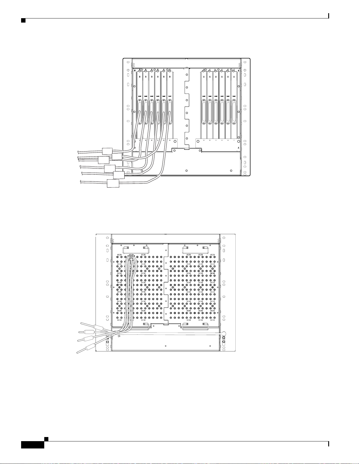
Ferrite Installation
Chapter 1 Hardware Installation
Figure 1-41 Attaching ferrites to AMP Champ connectors
32088
Figure 1-42 shows the suggested method for attaching ferrites to baluns. Use an oval ferrite TDK ZCAT
1730-0730 for each ca ble.
Figure 1-42 Attaching ferrites to electrical interface adapters (baluns)
B
A
32090
Figure 1-43 shows the suggested method for attach ing ferrites to SMB/BNC connectors. Use an oval
ferrite TDK ZCAT1730-0730 for each cable and place the ferrite as close to the connector as possible.
1-62
Cisco ONS 15454 Installation and Operations Guide
November 2001
 Loading...