

Page 1

CHAPTER
2
Cards Specifications
This chapter contains specific information about cards for dense wavelength division multiplexing
(DWDM) applications in the Cisco ONS 15454.
Note The terms"Unidirectional Path Switched Ring" and "UPSR" may appear in Cisco literature. These terms
do not refer to using Cisco ONS 15xxx products in a unidirectional path switched ring configuration.
Rather, these terms, as well as "Path Protected Mesh Network" and "PPMN," refer generally to Cisco's
path protection feature, which may be used in any topological network configuration. Cisco does not
recommend using its path protection feature in any particular topological network configuration.
The following topics are covered in this chapter:
• 2.1 Card Overview, page 2-1
• 2.2 Card Specifications, page 2-12
2.1 Card Overview
Redundant TCC2 and TCC2P cards are required to operate the Cisco ONS 15454. If you are using an
ETSI (SDH) shelf assembly,the MIC-A/P and MIC-C/T/P front mount electrical connections (FMECs)
are also required. The optional AIC-I card provides external alarms and controls (environmentalalarms).
Each DWDM card is marked with a symbol that corresponds to a slot (or slots) on the ONS 15454 shelf
assembly. These cards can only be installed into slots displaying the same symbols.
ONS 15454 DWDM cards are grouped into the following categories:
• Optical service channel OSC) cards provide bidirectional channels that connect all the ONS 15454
DWDM nodes and transport general-purpose information without affecting the client traffic.
ONS 15454 OSC cards include the Optical Service Channel Module (OSCM) and the Optical
Service Channel and Combiner/Separator Module (OSC-CSM).
• Optical erbium-doped fiber amplifier (EDFA) cards are used in amplified DWDM nodes, including
hub nodes, amplified OADM nodes, and line amplified nodes. Optical amplifier cards include the
Optical Preamplifier (OPT-PRE) and Optical Booster (OPT-BST).
• Dispersion compensation units (DCUs) are installed in the ONS 15454 dispersion compensation
shelf when optical preamplifier cards are installed in the DWDM node. Each DCU module can
compensate a maximum of 65 km of single-mode fiber (SMF-28) span. DCUs can be cascaded to
extend the compensation to 130 km.
July 2006
Cisco ONS 15454 DWDM Engineering and Planning Guide, Release 7.x
2-1
Page 2

2.1 Card Overview
Chapter 2 Cards Specifications
• Multiplexer and demultiplexercards multiplex and demultiplex DWDM optical channels. The cards
consist of three main modules: an optical plug-in, a microprocessor, and a DC/DC converter.
ONS 15454 multiplexer and demultiplexer cards include the 32-Channel Multiplexer (32MUX-O),
the 32-Channel Demultiplexer (32DMX-O), the single-slot 32-Channel Demultiplexer (32DMX),
and the 4-Channel Multiplexer/Demultiplexer (4MD-xx.x).
• Optical Add/Drop Multiplexer (OADM) cards are mainly divided into three groups: band OADM
cards, channel OADM cards, and wavelength selective switch (WSS) cards. Band OADM cards add
and drop one or four bands of adjacent channels; they include the 4-Band OADM (AD-4B-xx.x) and
the 1-Band OADM (AD-1B-xx.x). Channel OADM cards add and drop one, two, or four adjacent
channels; they include the 4-Channel OADM (AD-4C-xx.x), the 2-Channel OADM (AD-2C-xx.x)
and the 1-Channel OADM (AD-1C-xx.x). The 32-Channel Wavelength Selective Switch (32WSS)
card is used with the 32DMX to implement reconfigurable OADM (ROADM) functionality. These
cards consist of three main modules: an optical plug-in, a microprocessor, and a DC/DC converter.
Table 2-1 to Table 2-4 show the band IDs and the add/drop channel IDs for the 4MD-xx.x,
AD-2C-xx.x, AD-4C-xx.x, and AD-4B-xx.x cards.
Table 2-1 4MD-xx.x Channel Sets
Band IDs Add/Drop Channel IDs Add/Drop Wavelengths (nm)
Band 30.3 (A) 30.3, 31.2, 31.9, 32.6 1530.33, 1531.12, 1531.90,
1532.68
Band 34.2 (B) 34.2, 35.0, 35.8, 36.6 1534.25, 1535.04, 1535.82,
1536.61
Band 38.1 (C) 38.1, 38.9, 39.7, 40.5 1538.19, 1538.98, 1539.77,
1540.56
Band 42.1 (D) 42.1, 42.9, 43.7, 44.5 1542.14, 1542.94, 1543.73,
1544.53
Band 46.1 (E) 46.1, 46.9, 47.7, 48.5 1546.12, 1546.92, 1547.72,
1548.51
Band 50.1 (F) 50.1, 50.9, 51.7, 52.5 1550.12, 1550.92, 1551.72,
1552.52
Band 54.1 (G) 54.1, 54.9, 55.7, 56.5 1554.13, 1554.94, 1555.75,
1556.55
Band 58.1 (H) 58.1, 58.9, 59.7, 60.6 1558.17, 1558.98, 1559.79,
1560.61
2-2
Table 2-2 AD-2C-xx.x Channel Pairs
Band IDs Add/Drop Channel IDs Add/Drop Wavelengths (nm)
Band 30.3 (A) 30.3, 31.2 and 31.9, 32.6 1530.33, 1531.12 and 1531.90,
1532.68
Band 34.2 (B) 34.2, 35.0, and 35.8, 36.6 1534.25, 1535.04 and 1535.82,
1536.61
Band 38.1 (C) 38.1, 38.9 and 39.7, 40.5 1538.19, 1538.98 and 1539.77,
1540.56
Cisco ONS 15454 DWDM Engineering and Planning Guide, Release 7.x
July 2006
Page 3

Chapter 2 Cards Specifications
Table 2-2 AD-2C-xx.x Channel Pairs (continued)
Band IDs Add/Drop Channel IDs Add/Drop Wavelengths (nm)
Band 42.1 (D) 42.1, 42.9 and 43.7, 44.5 1542.14, 1542.94 and 1543.73,
Band 46.1 (E) 46.1, 46.9 and 47.7, 48.5 1546.12, 1546.92 and 1547.72,
Band 50.1 (F) 50.1, 50.9 and 51.7, 52.5 1550.12, 1550.92 and 1551.72,
Band 54.1 (G) 54.1, 54.9 and 55.7, 56.5 1554.13, 1554.94 and 1555.75,
Band 58.1 (H) 58.1, 58.9 and 59.7, 60.6 1558.17, 1558.98 and 1559.79,
Table 2-3 AD-4C-xx.x Channel Sets
Band IDs Add/Drop Channel IDs Add/Drop Wavelengths (nm)
Band 30.3 (A) 30.3, 31.2, 31.9, 32.6 1530.33, 1531.12, 1531.90,
Band 34.2 (B) 34.2, 35.0, 35.8, 36.6 1534.25, 1535.04, 1535.82,
Band 38.1 (C) 38.1, 38.9, 39.7, 40.5 1538.19, 1538.98, 1539.77,
Band 42.1 (D) 42.1, 42.9, 43.7, 44.5 1542.14, 1542.94, 1543.73,
Band 46.1 (E) 46.1, 46.9, 47.7, 48.5 1546.12, 1546.92, 1547.72,
Band 50.1 (F) 50.1, 50.9, 51.7, 52.5 1550.12, 1550.92, 1551.72,
Band 54.1 (G) 54.1, 54.9, 55.7, 56.5 1554.13, 1554.94, 1555.75,
Band 58.1 (H) 58.1, 58.9, 59.7, 60.6 1558.17, 1558.98, 1559.79,
2.1 Card Overview
1544.53
1548.51
1552.52
1556.55
1560.61
1532.68
1536.61
1540.56
1544.53
1548.51
1552.52
1556.55
1560.61
July 2006
Table 2-4 AD-4B-xx.x Channel Sets
Band IDs Add/Drop Channel IDs Add/Drop Wavelengths (nm)
Band 30.3 (A) B30.3 1530.33
Band 34.2 (B) B34.2 1534.25
Band 38.1 (C) B38.1 1538.19
Band 42.1 (D) B42.1 1542.14
Band 46.1 (E) B46.1 1546.12
Band 50.1 (F) B50.1 1550.12
Cisco ONS 15454 DWDM Engineering and Planning Guide, Release 7.x
2-3
Page 4

2.1 Card Overview
Chapter 2 Cards Specifications
Table 2-4 AD-4B-xx.x Channel Sets
Band IDs Add/Drop Channel IDs Add/Drop Wavelengths (nm)
Band 54.1 (G) B54.1 1554.13
Band 58.1 (H) B58.1 1558.17
• Transponder (TXP) and muxponder (MXP) cards convert the “gray” optical client interface signals
into trunk signals that operate in the “colored” DWDM wavelength range. Transponding or
muxponding is the process of converting the signals between the client and trunk wavelengths.
A muxponder generally handles several client signals. It aggregates, or multiplexes, lower- rate
client signals together and sends them out over a higher-rate trunk port. Likewise, a muxponder
demultiplexes optical signals coming in on a trunk and sends the signals out to individual client
ports. A transponder converts a single client signal to a single trunk signal and converts a single
incoming trunk signal to a single client signal.
All of the TXP and MXP cards perform optical-to-electrical-to-optical (OEO) conversion. As a
result, they are not optically transparent cards. OEO conversion is necessary because the cards must
operate on the signals passing through the cards.
However, the termination mode for all TXPs and MXPs can be configured as transparent
(termination is performed at the electrical level). In a transparent termination, neither the Line nor
the Section overhead is terminated. The cards can also be configured so that Line overhead, Section
overhead, or both Line and Section overhead can be terminated.
Note When configured in the transparent termination mode, the MXP_2.5G_10G card does terminate some
bytes by design.
Table 2-5 describes the Cisco ONS 15454 DWDM cards. Client-facing gray optical signals generally
operate at shorter wavelengths, whereas DWDM colored optical signals are in the longer wavelength
range (for example, 1490 nm = violet; 1510 nm = blue; 1530 nm = green; 1550 nm = yellow; 1570 nm
= orange; 1590 nm = red; 1610 nm = brown). Some of the newer client-facing SFPs, however, operate
in the colored region.
2-4
Cisco ONS 15454 DWDM Engineering and Planning Guide, Release 7.x
July 2006
Page 5

Chapter 2 Cards Specifications
2.1 Card Overview
Table 2-5 Cisco ONS 15454 DWDM Cards
Card Part Number Description
Optical Service Channel Cards
OSCM 15454-OSCM= The OSCM card has one set of optical ports and one Ethernet port
located on the faceplate. The card operates in Slots 8 and 10.
An OSC is a bidirectional channel connecting all the nodes in a ring.
The channel transports OSC overhead that is used to manage
ONS 15454 DWDM networks. The OSC uses the 1510 nm
wavelength and does not affect client traffic. The primary purpose of
this channel is to carry clock synchronization and orderwire channel
communications for the DWDM network. It also provides transparent
links between each node in the network. The OSC is an OC-3
formatted signal.
The OSCM is used in amplified nodes that include the OPT-BST
booster amplifier. The OPT-BST includes the required OSC
wavelengthcombiner and separator component. The OSCM cannot be
used in nodes where you use OC-N cards, electrical cards, or
cross-connect cards. The OSCM uses Slots 8 and 10 when the
ONS 15454 is configured in a DWDM network.
OSC-CSM 15454-OSC-CSM= The OSC-CSM card has three sets of optical ports and one Ethernet
port located on the faceplate. The card operates in Slots 1 to 6 and 12
to 17.
The OSC-CSM is identical to the OSCM, butalso contains a combiner
and separator module in addition to the OSC module.
The OSC-CSM is used in unamplified nodes. This means that the
booster amplifier with the OSC wavelength combiner and separator is
not required for OSC-CSM operation. The OSC-CSM can be installed
in Slots 1 to 6 and 12 to 17 when the ONS 15454 is configured in a
DWDM network.
Optical Amplifiers
OPT-PRE 15454-OPT-PRE= The OPT-PRE card is designed to support 64 channels at 50 GHz
channel spacing. The OPT-PREis a C-band DWDM,two-stage EDFA
with mid-amplifierloss (MAL) for allocation to a DCU. Tocontrolthe
gain tilt, the OPT-PRE is equipped with a built-in variable optical
attenuator (VOA). The VOA can also be used to pad the DCU to a
reference value. You can install the OPT-PRE in Slots 1 to 6 and 12 to
17 when the ONS 15454 is configured in a DWDM network.
OPT-BST 15454-OPT-BST= The OPT-BSTcardis designed to support up to 64 channels at 50 GHz
channel spacing. The OPT-BST is a C-band DWDM EDFA with OSC
add-and-drop capability. When an ONS 15454 DWDM has an
OPT-BST installed, it is only necessary to have the OSCM to process
the OSC. The card has a maximum output power of 17 dBm. To
control the gain tilt, the OPT-BST is equipped with a built-in VOA.
You can install the OPT-BST in Slots 1 to 6 and 12 to 17 when the
ONS 15454 is configured in a DWDM network.
July 2006
Cisco ONS 15454 DWDM Engineering and Planning Guide, Release 7.x
2-5
Page 6

Chapter 2 Cards Specifications
2.1 Card Overview
Table 2-5 Cisco ONS 15454 DWDM Cards (continued)
Card Part Number Description
OPT-BST-E 15454-OPT-BST-E= The OPT-BST-E card is designed to support up to 64 channels at
50 GHz channel spacing. It is a C-band DWDM EDFA with OSC
add-and-drop capability. Its maximum output power is 21 dBm. To
control the gain tilt, the OPT-BST-E is equipped with a built-in VOA.
You can install the OPT-BST-E in Slots 1 to 6 and 12 to 17 when the
ONS 15454 is configured in a DWDM network.
OPT-BST-L 15454-OPT-BST-L= The OPT-BST-L card is designed to support up to 64 channels at
50 GHz channel spacing. It is an L-band DWDM EDFA with OSC
add-and-drop capability. Its maximum output power is 17 dBm. To
control the gain tilt, the OPT-BST-L is equipped with a built-in VOA.
You can install the OPT-BST-L in Slots 1 to 6 and 12 to 17 when the
ONS 15454 is configured in a DWDM network.
OPT-AMP-L 15454-OPT-AMP-L= The OPT-AMP-L card is designed to support 64 channels at 50 GHz
channel spacing. The OPT-AMP-L is a L-band DWDM, two-stage
EDFA with MAL for allocation to a DCU. Its maximum output power
is 20 dBm. To control the gain tilt, the OPT-AMP-L is equipped with
a built-in VOA. The VOA can also be used to pad the DCU to a
reference value. OPT-AMP-Lis a double-slot card. You can install the
OPT-AMP-L in Slots 1-2, 3-4, 5-6, or in Slots 12-13, 14-15, or 16-17.
Multiplexer and Demultiplexer Cards
32MUX-O 15454-32MUX-O= The 32MUX-O card multiplexes 32 100 GHz-spaced channels
identified in the channel plan. The 32MUX-O card takes up two slots
in an ONS 15454 DWDM and can be installed in Slots 1 to 5 and 12
to 16.
32DMX-O 15454-32DMX-O= The 32DMX-O card demultiplexes 32 100-GHz-spaced channels
identifiedin the channel plan. The 32DMX-O takes up two slots in an
ONS 15454 DWDM and can be installed in Slots 1 to 5 and 12 to 16.
32DMX 15454-32DMX= The 32DMX card is a single-slot optical demultiplexer. The card
receives an aggregate optical signal on its COM RX port and
demultiplexes it into to 32 100-GHz-spaced channels. The 32DMX
card can be installed in Slots 1 to 6 and in Slots 12 to 17.
32DMX-L 15454-32DMX-L= The 32DMX-L card is a single-slot optical L-band demultiplexer. The
card receives an aggregate optical signal on its COM RX port and
demultiplexes it into to 32 100 GHz-spaced channels. The 32DMX
card can be installed in Slots 1 to 6 and in Slots 12 to 17.
4MD-xx.x 15454-4MD-xx.x= The 4MD-xx.x card multiplexes and demultiplexes four
100 GHz-spaced channels identified in the channel plan. The
4MD-xx.x card is designed to be used with band OADMs (both
AD-1B-xx.x and AD-4B-xx.x). There are eight versions of this card
that correspond with the eight subbands specified in Table 2-1 on
page 2-2. The 4MD-xx.x can be installed in Slots 1 to 6 and 12 to 17
when the ONS 15454 is configured in a DWDM network.
Optical Add/Drop Multiplexer Cards
2-6
Cisco ONS 15454 DWDM Engineering and Planning Guide, Release 7.x
July 2006
Page 7

Chapter 2 Cards Specifications
2.1 Card Overview
Table 2-5 Cisco ONS 15454 DWDM Cards (continued)
Card Part Number Description
AD-1C-xx.x 15454-AD-1C-xx.x= The AD-1C-xx.x card passively adds or drops one of the 32 channels
utilized within the 100 GHz-spacing of the DWDM card. There are
thirty-two versions of this card, each designed only for use with one
wavelength. Each wavelength version of the card has a different part
number. The AD-1C-xx.x can be installed in Slots 1 to 6 and 12 to 17
when the ONS 15454 is configured in a DWDM network.
AD-2C-xx.x 15454-AD-2C-xx.x= The AD-2C-xx.x card passively adds or drops two adjacent 100-GHz
channels within thesame band. There are sixteen versions of this card,
each designed for use with one pair of wavelengths. The card
bidirectionally adds and drops in two different sections on the same
card to manage signal flow in both directions. Each version of the card
has a different part number.TheAD-2C-xx.xcards are provisioned for
the channel pairs in Table 2-2 on page 2-2. In this table, channel IDs
are provided instead ofwavelengths.The AD-2C-xx.x can be installed
in Slots 1 to 6 and 12 to 17 when the ONS 15454 is configured in a
DWDM network.
AD-4C-xx.x 15454-AD-4C-xx.x= The AD-4C-xx.x card passively adds or drops all four
100 GHz-spaced channels within the same band. There are eight
versions of this card, each designed for use with one band of
wavelengths. The card bidirectionally adds and drops two different
sections on the same card to manage signal flow in both directions.
Each version of this card has a different part number.The AD-4C-xx.x
cards are provisioned for the channel pairs in Table 2-3 on page 2-3.
In this table, channel IDs are given rather than wavelengths. The
AD-4C-xx.x can be installed in Slots 1 to 6 and 12 to 17 when the
ONS 15454 is configured in a DWDM network.
AD-1B-xx.x 15454-AD-1B-xx= The AD-1B-xx.x card passively adds or drops a single band of four
adjacent 100 GHz-spaced channels. There are eight versions of this
card with eight different part numbers, each version designed for use
with one band of wavelengths. The card bidirectionally adds and
drops in two different sections on the same card to manage signal flow
in both directions. This card can be used when there is asymmetric
adding and dropping on each side (east or west) of the node; a band
can be added or dropped on one side but not on the other. The
AD-1B-xx.x can be installed in Slots 1 to 6 and 12 to17 when the
ONS 15454 is configured in a DWDM network.
AD-4B-xx.x 15454-AD-4B-xx= The AD-4B-xx.x card passively adds or drops four bands of four
adjacent 100 GHz-spaced channels. There are two versions of this
card with different part numbers, each version designed for use with
one set of bands. The card bidirectionally adds and drops in two
different sections on the same card to manage signal flow in both
directions. This card can be used when thereis asymmetric adding and
dropping on each side (east or west) of the node; a band can be added
or dropped on one side but not on the other.The AD-4B-xx.x cards are
provisioned for the channel pairs in Table 2-4 on page 2-3. In this
table, channel IDs are givenrather than wavelengths. The AD1B-xx.x
can be installed in Slots 1 to 6 and 12 to 17 when the ONS 15454 is
configured in a DWDM network.
July 2006
Cisco ONS 15454 DWDM Engineering and Planning Guide, Release 7.x
2-7
Page 8

Chapter 2 Cards Specifications
2.1 Card Overview
Table 2-5 Cisco ONS 15454 DWDM Cards (continued)
Card Part Number Description
32WSS 15454-32WSS= The 32WSS card has seven sets of ports located on the faceplate. The
card takes up two slots and operates in Slots 1-2, 3-4, 5-6, 12-13,
14-15, or 16-17. The 32WSS card performs channel add/drop
processing within the ONS 15454 DWDM node. The 32WSS card
works in conjunction with the 32DMX card to implement ROADM
functionality. Equipped with ROADM functionality, the ONS 15454
DWDM can be configured to add or drop individual optical channels
using Cisco Transport Controller (CTC), Cisco MetroPlanner, and
Cisco Transport Manager (CTM). A ROADM network element
utilizes two 32WSS cards (two slots each) and two 32DMX cards (one
slot each), for a total of six slots in the chassis.
32WSS-L — The 32WSS-L card has seven sets of ports located on the faceplate.
The card takes up two slots and operates in Slots 1-2, 3-4, 5-6,12-13,
14-15, or 16-17. The 32WSS-L card performs channel add/drop
processing in the L band. The 32WSS-L card works in conjunction
with the 32DMX-L card to implement ROADM functionality.
Equipped with ROADMfunctionality, the ONS 15454 DWDM can be
configured to add and drop or pass through each individual optical
channel.
MMU — The MMU card supports multiring and mesh upgrades for ROADM
nodes in both the C band and the L band. Mesh/multiring upgrade is
the capability to optically bypass a givenwavelengthfrom one section
of the network or ring to another one without requiring 3R
regeneration. In each node, you need to install two MMU cards, one
on the east side and one on the west side. The MMU card has six sets
of ports located on the faceplate. It operates in Slots 1 to 6 and 12 to
17.
Transponder and Muxponder Cards
TXP_MR_10G 15454-10T-L1-xx.x= The 10 Gbps Transponder-100 GHz-Tunable xx.xx-xx.xx card
(TXP_MR_10G) has twosets of ports located on the faceplateand can
be in Slots 1 to 6 and 12 to 17. It processes one 10-Gbps signal (client
side) into one 10-Gbps, 100-GHz DWDM signal (trunk side). It
provides one 10-Gbps port per card that can be provisioned for an
STM64/OC-192 short reach (1310 nm) signal, compliant with ITU-T
G.707, ITU-T G.709, ITU-T G.691, and Telcordia GR-253-CORE, or
to 10GE-BASE-LR, compliant with IEEE 802.3. Each version of this
card has a different part number.
The TXP_MR_10G card is tunable over two neighboring wavelengths
in the 1550 nm, ITU 100 GHz range. It is available in sixteen different
versions, covering thirty-two different wavelengths in the 1550 nm
range.
2-8
Cisco ONS 15454 DWDM Engineering and Planning Guide, Release 7.x
July 2006
Page 9

Chapter 2 Cards Specifications
2.1 Card Overview
Table 2-5 Cisco ONS 15454 DWDM Cards (continued)
Card Part Number Description
TXP_MR_10E 15454-10E-L1-xx.x= The 10 Gbps Transponder-100 GHz-Tunable xx.xx-xx.xx
(TXP_MR_10E) card has two sets of ports located on the faceplate
and can be installed in Slots 1 to 6 and Slots 12 to 17. It is a multirate
transponder for the ONS 15454 platform. It processes one 10-Gbps
signal (client side) into one 10-Gbps, 100-GHz DWDM signal (trunk
side) that is tunable on four wavelength channels (ITU-T 100-GHz
grid). Each version of this card has a different part number.
You can provision this card in a linear configuration,bidirectional line
switched ring (BLSR), a path protection, or a hub. The card can be
used in the middle of BLSR or 1+1 spans when the card is configured
for transparent termination mode.
The TXP_MR_10E port features a 1550-nm laser for the trunk port
and an ONS-XC-10G-S1 XFP module for the client port and contains
two transmit and receive connector pairs (labeled) on the card
faceplate.
The TXP_MR_10E card is tunable over four wavelengths in the
1550 nm ITU 100 GHz range. They are available in eight versions,
covering thirty-two different wavelengths in the 1550 nm range.
TXP_MR_10E-C 15454-10E-L1-C= This transponder has the same features as the TXP_MR_10E card, but
its trunk interface can be tuned over the entire C band.
TXP_MR_10E-L 15454-10E-L1-L= Thistransponder has the same features as the TXP_MR_10E card, but
its trunk interface can be tuned over the entire L band.
TXP_MR_2.5G 15454-MR-L1-xx.x= The 2.5 Gbps Multirate Transponder-100 GHz-Tunable xx.xx-xx.xx
(TXP_MR_2.5G) card has two sets of ports located on the faceplate
and can be installed in Slots 1 to 6 and Slots 12 to 17. It processes one
8 Mbps to2.488 Gbps signal (client side) into one 8 Mbps to 2.5 Gbps,
100-GHz DWDM signal (trunk side). It provides one long-reach
STM-16/OC-48 port per card, compliant with ITU-T G.707, ITU-T
G.709, ITU-T G.957, and Telcordia GR-253-CORE. Each version of
this card has a different part number.
The TXP_MR_2.5G card is tunable over four wavelengths in the
1550 nm ITU 100-GHz range. The card is available in eight versions,
covering thirty-two different wavelengths in the 1550 nm range. The
TXP_MR_2.5G card supports 2R (reshape and regenerate) and 3R
(retime, reshape and regenerate) modes of operation where the client
signal is mapped into a ITU-T G.709 frame.
July 2006
Cisco ONS 15454 DWDM Engineering and Planning Guide, Release 7.x
2-9
Page 10

Chapter 2 Cards Specifications
2.1 Card Overview
Table 2-5 Cisco ONS 15454 DWDM Cards (continued)
Card Part Number Description
TXPP_MR_2.5G 15454-MRP-L1-xx.x= The 2.5 Gbps Multirate Transponder-Protected-100 GHz-Tunable
xx.xxxx. xx (TXPP_MR_2.5G) card has three sets of ports located on
the faceplate and can be installed in Slots 1 to 6 and Slots 12 to 17. It
processes one 8 Mbps to 2.488 Gbps signal (client side) into two 8
Mbps to 2.5 Gbps, 100-GHz DWDM signals (trunk side). It provides
two long-reach STM-16/OC-48 ports per card, compliant with ITU-T
G.707, ITU-T G.957, and Telcordia GR-253-CORE. Each version of
this card has a different part number.
The TXPP_MR_2.5G card is tunable over four wavelengths in the
1550 nm ITU 100-GHz range. The card is available in eight versions,
covering thirty-two different wavelengths in the 1550 nm range. The
TXPP_MR_2.5G card support 2R and 3R modes of operation where
the client signal is mapped into a ITU-T G.709 frame.
MXP_2.5G_10G 15454-10M-L1-xx.x= The 2.5 Gbps-10 Gbps Muxponder-100 GHz-Tunable xx.xx-xx.xx
(MXP_2.5G_10G) card has 9 sets of ports located on the faceplateand
can be installed in Slots 1 to 6 and Slots 12 to 17. It
multiplexes/demultiplexesfour2.5-Gbps signals (client side) into one
10-Gbps, 100-GHz DWDM signal (trunk side). It provides one
extended long-range STM-64/OC-192 port per card on the trunk side
(compliant with ITU-T G.707, ITU-T G.709, ITU-T G.957, and
Telcordia GR-253-CORE) and four intermediate- or short-range
OC-48/STM-16 ports per card on the client side. The port operates at
9.95328 Gbps over unamplifieddistances up to 80 km (50 miles) with
different types of fiber such as C-SMF or dispersion compensated
fiber limited by loss and/or dispersion. The port can also operate at
10.70923 Gbps in ITU-T G.709 Digital Wrapper/FEC mode. Each
version of this card has a different part number.
Client ports on the MXP_2.5G_10G card are also interoperable with
OC-1 (STS-1) fiber-opticsignals definedin TelcordiaGR-253-CORE.
An OC-1 signal is the equivalent of one DS-3 channel transmitted
across optical fiber. OC-1 is primarily used for trunk interfaces to
phone switches in the United States.
The MXP_2.5G_10G card is tunable over two neighboring
wavelengths in the 1550 nm, ITU 100-GHz range. It is available in
sixteen different versions, covering thirty-two different wavelengths
in the 1550 nm range.
MXPP_2.5G_10G 15454-
2-10
Cisco ONS 15454 DWDM Engineering and Planning Guide, Release 7.x
July 2006
Page 11

Chapter 2 Cards Specifications
2.1 Card Overview
Table 2-5 Cisco ONS 15454 DWDM Cards (continued)
Card Part Number Description
MXP_2.5G_10E 15454-10ME-xx.x= The 2.5 Gbps-10 Gbps Muxponder-100 GHz-Tunable xx.xx-xx.xx
(MXP_2.5G_10E) card has nine sets of ports located on the faceplate
and can be installed in Slots 1 through 6 and 12 through 17. It is a
DWDM muxponder for the ONS 15454 platform that supports full
optical transparency on the client side. The card multiplexes four 2.5
Gbps client signals (4 x OC48/STM-16 SFP) into a single 10-Gbps
DWDM optical signal on the trunk side. The MXP_2.5G_10E card
provides wavelength transmission service for the four incoming 2.5
Gbps client interfaces. It passes all SONET overhead bytes
transparently. Each version of this card has a different part number.
The MXP_2.5G_10E workswith Optical TransparentNetwork(OTN)
devices defined in ITU-T G.709. The card supports Optical Data
Channel Unit 1 (ODU1) to Optical Channel Transport Unit (OTU2)
multiplexing, an industry standard method for asynchronously
mapping a SONET/SDH payload into a digitally wrapped envelope.
The MXP_2.5G_10E card is tunable over four neighboring
wavelengths in the 1550 nm, ITU 100-GHz range. It is available in
eight different versions, covering thirty-two different wavelengths in
the 1550 nm range. It is not compatible with the MXP_2.5G_10G
card, which does not supports full optical transparency.The faceplate
designation of the card is “4x2.5G 10E MXP.”
MXP_2.5G_10E-C 15454-10ME-C= This muxponder has the same features as the MXP_2.5G_10E card,
but its trunk interface can be tuned over the entire C band.
MXP_2.5G_10E-L 15454-10ME-L= This muxponder has the same features as the MXP_2.5G_10E card,
but its trunk interface can be tuned over the entire L band.
MXP_MR_2.5G 15454-Datamux2.5GDM The MXP_MR_2.5G card has nine sets of ports located on the
faceplate. The MXP_MR_2.5G card aggregates a mix and match of
client Storage Area Network (SAN) service client inputs (GE,
FICON, Fibre Channel, and ESCON) into one 2.5 Gbps
STM-16/OC-48 DWDM signal on the trunk side. It provides one
long-reach STM-16/OC-48 port per card and is compliant with
Telcordia GR-253-CORE.
MXPP_MR_2.5G 15454-Datamux2.5GDMP The MXPP_MR_2.5G card has ten sets of ports located on the
faceplate. The 2.5-Gbps Multirate Muxponder-Protected-100
GHz-Tunable 15xx.xx-15yy.yy (MXPP_MR_2.5G) card aggregates
various client SAN service client inputs (GE, FICON, Fibre Channel,
and ESCON) into one 2.5 Gbps STM-16/OC-48 DWDM signal on the
trunk side. It provides two long-reach STM-16/OC-48 ports per card
and is compliant with ITU-T G.957 and Telcordia GR-253-CORE.
July 2006
Cisco ONS 15454 DWDM Engineering and Planning Guide, Release 7.x
2-11
Page 12

Chapter 2 Cards Specifications
2.2 Card Specifications
Table 2-5 Cisco ONS 15454 DWDM Cards (continued)
Card Part Number Description
MXP_MR_10DME_C 15454-10DME-C= The MXP_MR_10DME_C and MXP_MR_10DME_L cards
MXP_MR_10DME_L 15454-10DME-L=
aggregate a mix of client SAN service client inputs (GE, FICON, and
Fibre Channel) into one 10-Gbps STM-64/OC-192 DWDM signal on
the trunk side. It provides one long-reach STM-64/OC-192 port per
card and is compliant with Telcordia GR-253-CORE and ITU-T
G.957. They pass all SONET/SDH overhead bytes transparently.
The ITU-T G.709 compliant digital wrapper function formats the
DWDM wavelength so that it can be used to set up generic
communications channels (GCCs) for data communications, enable
forward error correction (FEC), or facilitate performance monitoring
(PM). The cards work with the OTN devices defined in ITU-T G.709.
The cards support ODU1 to OTU2 multiplexing, an industry standard
method for asynchronously mapping a SONET/SDH payload into a
digitally wrapped envelope. You can install MXP_MR_10DME_C
and MXP_MR_10DME_L cards in Slots 1 to 6 and 12 to 17.
The MXP_MR_10DME_C card features a tunable 1550-nm C-band
laser on the trunk port. The laser is tunable across 82 wavelengths on
the ITU grid with 50-GHz spacing between wavelengths. The
MXP_MR_10DME_L features a tunable 1580-nm L-band laser on the
trunk port. The laser is tunable across 80 wavelengthson the ITU grid,
also with 50-GHz spacing. Each card features four 1310-nm lasers on
the client ports and contains five transmit and receive connector pairs
(labeled) on the card faceplate. The cards use dual LC connectors on
the trunk side and use SFP modules on the client side for optical cable
termination. The SFP pluggable modules are SR or IR and support an
LC fiber connector.
2.2 Card Specifications
Refer to the “Card Reference” chapter in the Cisco ONS 15454 DWDM Reference Manual for a detailed
description of each card.
2.2.1 Common Control Cards
This section describes the common control cards (TCC2, TCC2P, AIC-I, and MS-ISC-100T).
2.2.1.1 TCC2 Card
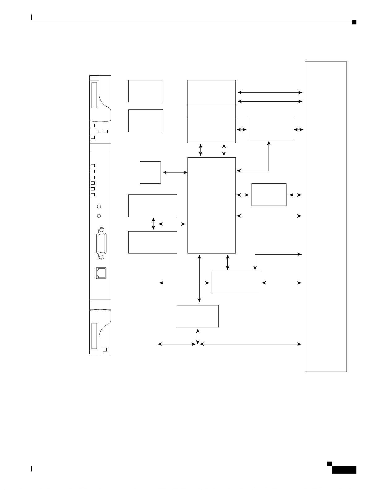
The Advanced Timing, Communications, and Control (TCC2) card performs system initialization,
provisioning, alarm reporting, maintenance, diagnostics, IP address detection/resolution, SONET
section overhead (SOH) data communications channel/generic communications channel (DCC/GCC)
termination, optical service channel (OSC) DWDM data communications network (DCN) termination,
and system fault detection for the ONS 15454. The TCC2 also ensures that the system maintains Stratum
3 (Telcordia GR-253-CORE) timing requirements. It monitors the supply voltage of the system.
Figure 2-1 shows the faceplate and block diagram for the TCC2.
Cisco ONS 15454 DWDM Engineering and Planning Guide, Release 7.x
2-12
July 2006
Page 13
Chapter 2 Cards Specifications
Figure 2-1 TCC2 Block Diagram and Faceplate
2.2.1 Common Control Cards
BACKPLANE
TCC2
FAIL
PWR
A
ACT/STBY
CRIT
MAJ
MIN
REM
SYNC
ACO
ACO
LAMP
RS-232
TCP/IP
-48V PWR
Monitors
System
Timing
FPGA
Real Time
Clock
B
DCC
Processor
TCCA ASIC
SCL Processor
Ref Clocks
(all I/O Slots)
BITS Input/
Output
SCL Links to
All Cards
HDLC
Serial
Debug
400MHz
Processor
MCC1
SCC1 SCC2
MCC2
SCC3
FCC1
Message
Modem
Interface
Bus
Modem
Interface
(Not Used)
Mate TCC2
HDLC Link
Communications
SDRAM Memory
& Compact Flash
Processor
FCC2SCC4
Mate TCC2
Ethernet Port
Backplane
Faceplate
Ethernet Port
Ethernet
Repeater
Ethernet Port
(Shared with
Mate TCC2)
July 2006
RS-232 Craft
Interface
Backplane
Faceplate
RS-232 Port
Note: Only 1 RS-232 Port Can Be Active -
RS-232 Port
(Shared with
Mate TCC2)
Backplane Port Will Supercede Faceplate Port
The TCC2 card terminates up to 32 DCCs. The TCC2 hardware is prepared for up to 84 DCCs, which
will be available in a future software release.
The node database, IP address, and system software are stored in TCC2 nonvolatile memory, which
allows quick recovery in the event of a power or card failure.
Cisco ONS 15454 DWDM Engineering and Planning Guide, Release 7.x
2-13
137639
Page 14

2.2.1 Common Control Cards
2.2.1.2 TCC2P Card
Chapter 2 Cards Specifications
The TCC2 performs all system-timing functions for each ONS 15454. The TCC2 monitors the recovered
clocks from each traffic card and two building integrated timing supply (BITS) ports for frequency
accuracy. The TCC2 selects a recovered clock, a BITS, or an internal Stratum 3 reference as the
system-timing reference. You can provision any of the clock inputs as primary or secondary timing
sources. A slow-reference trackingloop allows the TCC2 to synchronize with the recoveredclock, which
provides holdover if the reference is lost.
The TCC2 monitors both supply voltage inputs on the shelf. An alarm is generated if one of the supply
voltage inputs has a voltage out of the specified range.
Install TCC2 cards in Slots 7 and 11 for redundancy. If the active TCC2 fails, traffic switches to the
protect TCC2.
The TCC2 card has two built-in interface ports for accessing the system: an RJ-45 10BaseT LAN
interface and an EIA/TIA-232 ASCII interface for local craft access. It also has a 10BaseT LAN port for
user interfaces via the backplane.
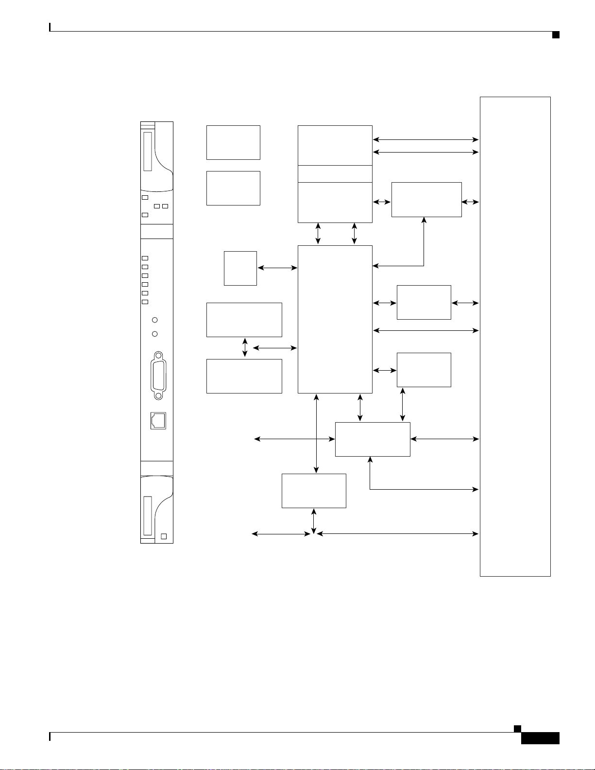
The Advanced Timing, Communications, and Control Plus (TCC2P) card is an enhanced version of the
TCC2 card. The primary enhancements are Ethernet security features and 64K composite clock BITS
timing.
The TCC2P card performs system initialization, provisioning, alarm reporting, maintenance,
diagnostics, IP address detection/resolution, SONET SOH DCC/GCC termination, and system fault
detection for the ONS 15454. The TCC2P also ensures that the system maintains Stratum 3 (Telcordia
GR-253-CORE) timing requirements. It monitors the supply voltage of the system.
Figure 2-2 shows the faceplate and block diagram for the TCC2P card.
2-14
Cisco ONS 15454 DWDM Engineering and Planning Guide, Release 7.x
July 2006
Page 15

Chapter 2 Cards Specifications
Figure 2-2 TCC2P Block Diagram and Faceplate
2.2.1 Common Control Cards
BACKPLANE
TCC2P
FAIL
PWR
A
ACT/STBY
CRIT
MAJ
MIN
REM
SYNC
ACO
ACO
LAMP
RS-232
Ref Clocks
-48V PWR
Monitors
System
Timing
(all I/O Slots)
BITS Input/
Output
FPGA
Real Time
Clock
B
DCC
Processor
TCCA ASIC
SCL Processor
SCL Links to
All Cards
HDLC
Serial
Debug
400MHz
Processor
MCC1
SMC1 SCC2
MCC2
SCC3
FCC1
Message
Modem
Interface
Bus
Modem
Interface
(Not Used)
Mate TCC2
HDLC Link
Communications
SDRAM Memory
& Compact Flash
Processor
SCC1
FCC2SCC4
Ethernet
Phy
TCP/IP
Faceplate
Ethernet Port
Ethernet Switch
Ethernet Port
(Shared with
Mate TCC2)
Backplane
EIA/TIA 232
Craft Interface
Mate TCC2
Ethernet Port
Backplane
Faceplate
EIA/TIA 232 Port
Note: Only 1 EIA/TIA 232 Port Can Be Active -
EIA/TIA 232 Port
(Shared with
Mate TCC2)
Backplane Port Will Supercede Faceplate Port
The TCC2P card supports multichannel, high-level data link control (HDLC) processing for the DCC.
Up to 84 DCCs can be routed over the TCC2P card and up to 84 section DCCs can be terminated at the
TCC2P card (subject to the available optical digital communication channels). The TCC2P selects and
processes 84 DCCs to facilitate remote system management interfaces.
The TCC2P card also originates and terminates a cell bus carried over the module. The cell bus supports
links between anytwo cards inthe node, which is essential for peer-to-peer communication. Peer-to-peer
communication accelerates protection switching for redundant cards.
145942
July 2006
Cisco ONS 15454 DWDM Engineering and Planning Guide, Release 7.x
2-15
Page 16

2.2.1 Common Control Cards
The node database, IP address, and system software are stored in TCC2P card nonvolatile memory,
which allows quick recovery in the event of a power or card failure.
The TCC2P card performs all system-timing functions for each ONS 15454. The TCC2P card monitors
the recovered clocks from each trafficcard and two BITS ports for frequency accuracy. The TCC2P card
selects a recovered clock, a BITS, or an internal Stratum 3 reference as the system-timing reference. You
can provision any of the clock inputs as primary or secondary timing sources. A slow-reference tracking
loop allows the TCC2P card to synchronize with the recovered clock, which provides holdover if the
reference is lost.
The TCC2P card supports 64/8K composite clock and 6.312 MHz timing output. The TCC2P card
monitors both supply voltage inputs on the shelf. An alarm is generated if one of the supply voltage
inputs has a voltage out of the specified range.
Install TCC2P cards in Slots 7 and 11 for redundancy. If the active TCC2P card fails, traffic switches to
the protect TCC2P card. All TCC2P card protection switches conform to protection switching standards
when the bit error rate (BER) counts are not in excess of1*10exp-3andcompletion time is less than
50 ms.
The TCC2P card has two built-in Ethernet interface ports for accessing the system: one built-in RJ-45
port on the front faceplate for on-site craft access and a second port on the backplane. The rear Ethernet
interface is for permanent LAN access and all remote access via TCP/IP as well as for Operations
Support System (OSS) access. The front and rear Ethernet interfaces can be provisioned with different
IP addresses using CTC.
Two EIA/TIA-232 serial ports, one on the faceplate and a second on the backplane, allow for craft
interface in TL1 mode.
Chapter 2 Cards Specifications
2.2.1.3 MS-ISC-100T Card
The MS-ISC-100T Ethernet LAN card (see Figure 2-3), which is a 12-port NEBS3 Ethernet Switch
running Cisco IOS. The MS-ISC-100T card must be equipped in an NC shelf; the preferred slots are 6
and 12. MS-ISC-100T Cisco IOS configuration is part of the software package and is automatically
loaded to the card at start-up. This configuration can be modified using the Cisco IOS command-line
interface (CLI) only. The CLI is disabled by default, but it can be enabled from the Cisco Transport
Controller (CTC) interface. All MS-ISC-100T ports are turned on by default. Using the CLI, you can
turn off ports that are not used.
2-16
Cisco ONS 15454 DWDM Engineering and Planning Guide, Release 7.x
July 2006
Page 17
Chapter 2 Cards Specifications
Figure 2-3 MS-ISC-100T Faceplate and Block Diagram
2.2.1 Common Control Cards
BACKPLANE
TCC2P
FAIL
PWR
A
ACT/STBY
CRIT
MAJ
MIN
REM
SYNC
ACO
ACO
LAMP
RS-232
Ref Clocks
-48V PWR
Monitors
System
Timing
(all I/O Slots)
BITS Input/
Output
FPGA
Real Time
Clock
B
DCC
Processor
TCCA ASIC
SCL Processor
SCL Links to
All Cards
HDLC
Serial
Debug
400MHz
Processor
MCC1
SMC1 SCC2
MCC2
SCC3
FCC1
Message
Modem
Interface
Bus
Modem
Interface
(Not Used)
Mate TCC2
HDLC Link
Communications
SDRAM Memory
& Compact Flash
Processor
SCC1
FCC2SCC4
Ethernet
Phy
TCP/IP
Faceplate
Ethernet Port
Ethernet Switch
Ethernet Port
(Shared with
Mate TCC2)
Backplane
EIA/TIA 232
Craft Interface
Mate TCC2
Ethernet Port
Backplane
Faceplate
EIA/TIA 232 Port
Note: Only 1 EIA/TIA 232 Port Can Be Active -
EIA/TIA 232 Port
(Shared with
Mate TCC2)
Backplane Port Will Supercede Faceplate Port
The MS-ISC-100T separates internal and external traffic using a VLAN.
A Cisco IOS configuration file assigns a specific role to each of MS-ISC-100T ports that are shown on
the card faceplates. They are as follows:
• DCN Port: Connected to external supervision
• SSC Port: Connected to a TCC2/TCC2P equipped in a subtended shelf
• NC Port: Connected to a TCC2/TCC2P equipped in an NC shelf
145942
July 2006
Cisco ONS 15454 DWDM Engineering and Planning Guide, Release 7.x
2-17
Page 18

2.2.2 Optical Service Channel Cards
• PROT: Connected to the other MS-ISC-100T ports
The TCC is connected to the MS LAN by its front panel port. The back panel Ethernet port is disabled
and cannot be used in the MS node.
2.2.2 Optical Service Channel Cards
The Optical Service Channel (OSC) is a bidirectional channel that connects all the nodes in a DWDM
ring that transports general-purpose information without affecting client traffic. In its primary
application, this channel carries data sub-channels for telemetry (supervisory) services for an optical
system, provides orderwire applications, and provides transparent links between each node of the
network for user-defined or proprietary functions.
The ONS 15454 has two OSC cards, the OSCM and the OSC-CSM.
Table 2-6 shows the optical specifications for the OSCM card.
Table 2-6 OSCM Card Optical Specifications
Parameter Condition Min Max Unit
OSC bandwidth at –0.5 dB OSCRX -> TX – OSCTX 1500 1520 nm
Insertion loss OSCRX -> TX – OSCTX — 1.4 dB
OSC band chromatic dispersion OSCRX -> TX – OSCTX –10 +10 ps/nm
Polarization Mode Dispersion (PMD) OSCRX -> TX – OSCTX — 0.1 ps
Polarization Dependent Loss (PDL) OSCRX -> TX – OSCTX 0-10dB 0.45 dB
Optical power setting accuracy — –0.5 +0.5 dB
Optical attenuation VOAosc power set
resolution (granularity)
Optical power stability — –0.2 +0.2 dB
Optical power setting time — — 200 ms
VOAosc dynamic range — 30 — dB
VOAosc off state AVS state 39 — dB
Directivity — 40 — dB
Return loss — 40 — dB
Chapter 2 Cards Specifications
— — 0.1 dB
2-18
Table 2-7 shows the optical specifications for the OSC-CSM card.
Table 2-7 OSC-CSM Card Optical Specifications
Parameter Condition Min Max Unit
OSC (–0.5 dB bandwidth) LINERX – OSC
OSCRX – LINE
Channels (–0,5 dB bandwidth) LINERX – COM
COMRX – LINE
Cisco ONS 15454 DWDM Engineering and Planning Guide, Release 7.x
TX
TX
TX
TX
1500 1520 nm
1529 1605 nm
July 2006
Page 19

Chapter 2 Cards Specifications
Table 2-7 OSC-CSM Card Optical Specifications (continued)
Parameter Condition Min Max Unit
Insertion loss LINERX – OSC
OSC crosstalk LINERX – OSC
Isolation LINERX – COM
OSC band chromatic dispersion LINERX – OSC
Channel band chromatic dispersion LINERX – COM
PMD Each optical path — 0.1 ps
PDL LINERX – COM
Optical power setting accuracy VOA in closed loop –0.5 +0.5 dB
Optical power setting time VOA in closed loop — 200 ms
VOAosc dynamic range — 30 — dB
VOAosc off state AVS state 39 — dB
Switch input lambda range COMRX – LINE
Switch open condition attenuation COMRX – LINE
Switching time Closed/Open COMRX – LINE
Directivity — 40 — dB
Return loss — 40 — dB
2.2.3 Optical Add and Drop Cards
0.5 1.4 dB
0.4 1.2 dB
1.2 2.2 dB
1.2 2.2 dB
30 — dB
–15 — dB
–20 +20 ps/nm
–20 +20 ps/nm
— 0.2 dB
— 0.5
1528 1605 nm
>40 — dB
—5ms
LINERX – COM
OSCRX – LINE
COMRX – LINE
OSCRX – LINE
COMRX – LINE
OSCRX – LINE
COMRX – LINE
LINERX – OSC
COMRX – LINE
OSCRX – LINE
TX
TX
TX
TX
TX
TX
TX
TX
TX
TX
TX
TX
TX
TX
TX
TX
TX
TX
TX
Open/Closed — 20
2.2.3 Optical Add and Drop Cards
This section describes the internal parameter and performance information for the 32WSS, 32WSS-L,
32DMX, 32DMX-L, 32DMX-O, 32DMX-L, AD-1B-xx.x, AD-4B-xx.x, AD-1C-xx.x, AD-2C-xx.x,
AD-4C-xx.x, and MMU cards.
2.2.3.1 32WSS Card
Table 2-8 defines internal parameter and performance details for the 32WSS card.
July 2006
Cisco ONS 15454 DWDM Engineering and Planning Guide, Release 7.x
2-19
Page 20

2.2.3 Optical Add and Drop Cards
Table 2-8 32WSS Card Parameters and Performance
Parameter Condition Min Typical Max Unit
Channel grid
–0.5 dB bandwidth EXP RX => COM TX +/–115 pm
–0.5 dB bandwidth Add 1, 32 => COM TX +/–135
Insertion loss EXP RX => COM TX — — 11.3 dB
Adjacent crosstalk Add 1, 32 23 — — dB
Multipath interference EXP RX => COM TX 45 — —
Nonadjacent crosstalk Add 1, 32 30 — —
PDL EXP RX => COM TX — — 0.9 dB
In-band chromatic
dispersion
Group delay ripple All paths –10 — +10 ps
In-band PMD All paths — — 0.5 ps
Optical power/VOA
attenuation setting
resolution
Optical power setting
accuracy
Optical power setting
precision
Optical power/VOA
attenuation settling time
Optical switch state
settling time
VOA dynamic range EXP RX => COM TX 20 — — dB
Channel shutoff
attenuation (AVS)
Optical port isolation EXP RX => COM TX 32 — — dB
Chapter 2 Cards Specifications
COM RX => EXP TX — — 1.5
Add 1, 32 => COM TX — — 7.6
COM RX => DROP TX 6 — 8.5
COM RX => EXP TX — — 0.1
Add 1, 32 => COM TX — — 0.5
COM RX => DROP TX — — 0.1
All paths –20 — +20 ps/nm
— — — 0.1 dB
— –0.5 — + 0.5 dB
— –0.1 — + 0.1 dB
— — — 200 ms
———5ms
———5
Add 1, 32 => COM TX 25 — —
EXP RX => COM TX 40 — — dB
Add 1, 32 => COM TX — —
EXP RX => COM TX 40 — —
Add 1, 32 => COM TX — —
Add 1, 32 => COM TX 42 45 —
2-20
Cisco ONS 15454 DWDM Engineering and Planning Guide, Release 7.x
July 2006
Page 21

Chapter 2 Cards Specifications
Table 2-8 32WSS Card Parameters and Performance (continued)
Parameter Condition Min Typical Max Unit
Directivity Add 1,32 <=> Add 1,32 40 — — dB
Return loss — 40 — — dB
Maximum optical input
power
Maximum AWG startup
time
2.2.3.2 32WSS-L Card
The 32WSS-L card is capable of operating bidirectionally over the L band of the optical spectrum
(wavelengths from 1577 nm to 1605 nm).
In one line direction, the EXP-RX port receives the aggregate optical signal. The first arrayed
wavelength grating (AWG) opens the spectrum and each wavelength goes through a 1x2 optical switch,
where the same wavelength can be added from its ADD port. A dedicated per-channel VOA allows
per-channel power regulation. The second AWG multiplexes all the wavelengths and the aggregate
signal goes through the COM-TX output port.
In the other line direction, the aggregate optical signal comes in from the COM-RX port. An 80/20
splitter (80 Express/20 Drop) sends the optical signals on two output ports, the DROP-TX port for
demultiplexing and dropping wavelengths, and the EXP-TX port for the next stage.
Each input and output port is equipped with either a real or a virtual photodiode. All VOAs for the
32 channels and switches are software-controlled for remote reconfiguration. Table 2-9 defines all
optical internal parameters and performances details.
2.2.3 Optical Add and Drop Cards
Add 1, 32 <=> EXP RX
— 300 — — mW
— — — 10 min.
Table 2-9 32WSS-L Card Parameters and Performance
Parameter Condition Min Typical Max Unit
–0.5 dB bandwidth EXP RX => COM TX +/–91 116 — pm
–0.5 dB bandwidth Add 1, 32 => COM TX +/–135 161 —
Insertion loss EXP RX => COM TX — 9.7 11.3 dB
COM RX => EXP TX — 1.4 1.6
Add 1, 32 => COM TX — 6.2 8.0
COM RX => DROP TX 6 8 8.5
Adjacent crosstalk Add 1, 32 23 30 — dB
Multi path interference EXP RX => COM TX 41 49 —
Nonadjacent crosstalk Add 1, 32 30 42 —
PDL EXP RX => COM TX — 0.5 0.9 dB
COM RX => EXP TX — 0.5 0.9
Add 1, 32 => COM TX — 0.7 1.5
COM RX => DROP TX — 0.7 1.3
July 2006
Cisco ONS 15454 DWDM Engineering and Planning Guide, Release 7.x
2-21
Page 22

2.2.3 Optical Add and Drop Cards
Table 2-9 32WSS-L Card Parameters and Performance (continued)
Parameter Condition Min Typical Max Unit
In-band chromatic
dispersion
Group delay ripple All paths –10 — +10 ps
In-band PMD All paths — — 1 ps
Optical power/VOA
attenuation setting
resolution
Optical power setting
accuracy
Optical power setting
precision
Optical power/VOA
attenuation settling time
Optical switch state
settling time
VOA dynamic range EXP RX => COM TX 20 25 — dB
Channel shutoff
attenuation (AVS)
Optical port isolation EXP RX => COM TX 27 33 — dB
Directivity Add 1,32 <=> Add 1,32 40 — — dB
Return loss — 40 — — dB
Maximum optical input
power
Maximum AWG startup
time
Chapter 2 Cards Specifications
All paths –20 — +20 ps/nm
— — — 0.1 dB
— –0.7 0.1 + 0.7 dB
— –0.4 0.1 + 0.4 dB
— — — 200 ms
———5ms
———5
Add 1, 32 => COM TX 25 25 —
EXP RX => COM TX 28 45 — dB
Add 1, 32 => COM TX —
EXP RX => COM TX 39 50 —
Add 1, 32 => COM TX —
Add 1, 32 => COM TX 36 50 —
Add 1, 32 <=> EXP RX
— 300 — — mW
— — — 10 min.
The 32WSS-L card supports OChSPRing protection. This implies that the optical plug-in module needs
to perform a switch fast enough to allow a total unit switching time of less than 10 ms.
The 32WSS-L is a double-slot card that has three LEDs on its front panel.
2.2.3.3 32DMX Card
Table 2-10 defines the 32DMX card optical parameters and the maximum insertion loss allowed.
Cisco ONS 15454 DWDM Engineering and Planning Guide, Release 7.x
2-22
July 2006
Page 23

Chapter 2 Cards Specifications
Table 2-10 32DMX Card Optical Parameters and Insertion Loss
Parameter Condition Min Typical Max Unit
–1 dB Bandwidth COM RX => TX 1, 32
–3 dB Bandwidth +/–200 — —
Insertion Loss COM RX => TX 1, 32 — — 5.5 dB
Adjacent Crosstalk COM RX => TX 1, 32 26 — — dB
Nonadjacent Crosstalk 34 — —
Total Crosstalk 20 — —
PDL COM RX => TX 1, 32 — — 0.5 dB
In Band Chromatic
Dispersion
Group Delay Ripple All paths –10 — +10 ps
In Band PMD All paths — — 0.5 ps
VOA attenuation Setting
Resolution
VOAAttenuationSetting
Accuracy
VOAAttenuationSetting
Precision
Power Monitoring
Indication Response
Time Internal Cycle
Optical Power/VOA
Attenuation Settling time
VOA shut-off
Attenuation (AVS)
Directivity — 40 — — dB
Return Loss — 40 — — dB
Maximum Optical input
power
MaximumAWG Start-up
time
2.2.3 Optical Add and Drop Cards
+/–110 — — pm
(OUT)
All paths –20 — +20 ps/nm
— — — 0.1 dB
Attenuation range
–0.5 + 0.5 dB
0 – 10 dB
Attenuation range
–0.1 + 0.1 dB
0 – 10 dB
All PDs (both real and
— — 20 ms
virtual)
— — — 200 ms
COM RX => TX 1, 32 40 — — dB
— 300 — — mW
— — — 10 min.
2.2.3.4 32DMX-L Card
The 32DMX-L is a unidirectional unit that operates over the L band of the optical spectrum in
wavelengths from 1577 nm to 1605 nm. The 32DMX-L card receives the aggregate optical signal
through the COM-RX port and demultiplexes all 32 wavelengths onto its output ports. Every port has a
photodiode for optical power monitoring. The common path is equipped with a common VOA for optical
power regulation.
The single VOA on the common path is the main difference between the 32DMX-L card and the
32DMX-O card, which has 32 VOAs, one for each output port. The 32DMX-L cannot provide power
regulation for each individual channel.
July 2006
Cisco ONS 15454 DWDM Engineering and Planning Guide, Release 7.x
2-23
Page 24

2.2.3 Optical Add and Drop Cards
When output ports are connected to the client equipment, an external bulk attenuator might be required
to match the receive (Rx) window of the interface. Table 2-11 defines the internal optical parameters.
Table 2-11 32DMX-L Card Optical Parameters
Parameter Condition Min Typical Max Unit
–1 dB bandwidth COM RX => TX 1, 32
–3 dB bandwidth +/–200 — —
Insertion loss COM RX => TX 1, 32 — — 5.8 dB
Adjacent crosstalk COM RX => TX 1, 32 25 — — dB
Nonadjacent crosstalk 34 — —
Total crosstalk 20 — —
PDL COM RX => TX 1, 32 — — 0.5 dB
In-band chromatic
dispersion
Group delay ripple All paths –10 — +10 ps
In-band PMD All paths — — 0.5 ps
VOA attenuation
setting resolution
VOA attenuation
setting accuracy
VOA attenuation
setting precision
Power monitoring
indication response
time internal cycle
Optical power/VOA
attenuation settling
time
VOA shutoff
attenuation (AVS)
Directivity — 40 — — dB
Return loss — 40 — — dB
Maximum optical
input power
Maximum AWG
startup time
Chapter 2 Cards Specifications
+/–100 — — pm
(OUT)
All paths –20 — +20 ps/nm
— — — 0.1 dB
Attenuation range
– 0.7 — + 0.7 dB
0 – 10 dB
Attenuation range
–0.1 — + 0.1 dB
0 – 10 dB
All PDs (both real and
— — 20 ms
virtual)
— — — 200 ms
COM RX => TX 1, 32 40 — — dB
— 300 — — mW
— — — 10 min.
2.2.3.5 32MUX-O Card
Table 2-12 defines the optical parameters for the 32MUX-O card.
Cisco ONS 15454 DWDM Engineering and Planning Guide, Release 7.x
2-24
July 2006
Page 25

Chapter 2 Cards Specifications
Table 2-12 32MUX-O Card Optical Parameters
Parameter Min Typical Max Unit
–1 dB bandwidth 160 — 300 pm
In-band ripple — — 0.5 dB
Insertion loss 4 — 8.5 dB
Insertion loss disuniformity — — 1.5 dB
Adjacent crosstalk 23 — — dB
Nonadjacent crosstalk 30 — — dB
Total crosstalk 20 — — dB
PDL — — 1.5 dB
In-band chromatic dispersion –20 — +20 ps/nm
In-band PMD — — 0.5 ps
Optical power/VOA attenuation setting
resolution
Optical power setting accuracy –0.5 — +0.5 dB
VOA attenuation setting accuracy –0.1 — +0.1 dB
Power monitoring indication response time — — 20 ms
Optical power/VOA attenuation settling
time
Optical rise and fall time — — 200 ms
Optical over and undershoot –1.5 — +1.5 dB
VOA dynamic range 25 — — dB
VOA shutoff attenuation (AVS) with unit
powered off
VOA shutoff attenuation (AVS) with unit
powered on
Directivity 40 — — dB
Return loss 40 — — dB
Optical monitor tap splitting ratio on
monitor port
Maximum optical input power 300 — — mW
Maximum AWG startup time — — 10 min.
2.2.3 Optical Add and Drop Cards
— — 0.1 dB
— — 200 ms
20——dB
40——dB
19 — 21 dB
2.2.3.6 32DMX-O Card
Table 2-13 defines the optical parameters for the 32DMX-O card.
July 2006
Cisco ONS 15454 DWDM Engineering and Planning Guide, Release 7.x
2-25
Page 26

2.2.3 Optical Add and Drop Cards
Table 2-13 32DMX-O Card Optical Parameters
Parameter Min Typical Max Unit
–1 dB bandwidth 160 — 300 pm
In-band ripple — — 0.5 dB
Insertion loss 4 — 8.5 dB
Insertion loss disuniformity — — 1.5 dB
Adjacent crosstalk 23 — — dB
Nonadjacent crosstalk 30 — — dB
Total crosstalk 20 — — dB
PDL — — 1.5 dB
In-band chromatic dispersion –20 — +20 ps/nm
In-band PMD — — 0.5 ps
Optical power/VOA attenuation setting
resolution
Optical power setting accuracy –0.5 — +0.5 dB
VOA attenuation setting accuracy –0.1 — +0.1 dB
Power monitoring indication response time — — 20 ms
Optical power/VOA attenuation settling
time
Optical rise and fall time — — 200 ms
Optical over and undershoot –1.5 — +1.5 dB
VOA dynamic range 25 — — dB
VOA shutoff attenuation (AVS) with unit
Powered Off
VOA shutoff attenuation (AVS) with unit
powered on
Directivity 40 — — dB
Return loss 40 — — dB
Optical monitor tap splitting ratio on
monitor port
Maximum optical input power 300 — — mW
Maximum AWG startup time — — 10 min.
Chapter 2 Cards Specifications
— — 0.1 dB
— — 200 ms
20——dB
40——dB
19 — 21 dB
2.2.3.7 4MD-xx.x Card
Table 2-14 defines optical parameters for the 4MD-xx.xx card.
Cisco ONS 15454 DWDM Engineering and Planning Guide, Release 7.x
2-26
July 2006
Page 27

Chapter 2 Cards Specifications
Table 2-14 4MD-xx.x Card Optical Parameters
Optical Parameters Value
Maximum insertion loss demultiplex section 3.2 dB
Maximum insertion loss multiplex section 3.6 dB at VOA min attenuation
Adjacent crosstalk 25 dB
Nonadjacent crosstalk 38 dB
VOA dynamic range 30 dB
2.2.3.8 C-Band OADM Filter Cards
Table 2-15 to Table 2-19 define optical parameters for the AD-1B-xx.x, AD-4B-xx.x, AD-1C-xx.x,
AD-2C-xx.x, and AD-4C-xx.x cards.
Table 2-15 AD-1B-xx.x Card Optical Parameters
Optical Parameters Value
Maximum insertion loss drop section 3 dB at VOA minimum attenuation
Maximum insertion loss add section 2.2 dB
Maximum insertion loss express section
(Exp RX – COM TX)
Maximum insertion loss express section
(COM RX – Exp TX)
In-band ripple 0.3 dB
Out-of-band ripple (COM RX – Exp TX) 0.5 dB at VOA minimum attenuation
Out-of-band ripple (Exp RX – COM TX) 0.3 dB
Left/Right adjacent crosstalk 25 dB
First channel nonadjacent crosstalk 30 dB
Nonadjacent crosstalk 35 dB
Left/Right isolation drop path –26 dB
Left/Right isolation add path –13 dB
2.2.3 Optical Add and Drop Cards
1.6 dB
2.8 dB at VOA minimum attenuation
July 2006
Table 2-16 AD-4B-xx.x Card Optical Parameters
Optical Parameters Value
Maximum insertion loss drop section 4.5 dB at VOA minimum attenuation
Maximum insertion loss add section 3.5 dB
Maximum insertion loss express section
3dB
(Exp RX – COM TX)
Maximum insertion loss express section
4.8 dB at VOA minimum attenuation
(COM RX – Exp TX)
In-Band Ripple 0.3 dB
Cisco ONS 15454 DWDM Engineering and Planning Guide, Release 7.x
2-27
Page 28

2.2.3 Optical Add and Drop Cards
Table 2-16 AD-4B-xx.x Card Optical Parameters (continued)
Optical Parameters Value
In-band ripple 0.5 dB at VOA minimum attenuation
Out-of-band ripple (COM RX – Exp TX) 0.3 dB
Left/Right adjacent crosstalk 25 dB
First channel nonadjacent crosstalk 30 dB
Nonadjacent crosstalk 35 dB
Left/Right isolation drop path –26 dB
Left/Right isolation add path –13 dB
Table 2-17 AD-C-xx.x Card Optical Parameters
Optical Parameters Value
Maximum insertion loss drop section 2 dB
Maximum insertion loss add section 2.6 dB at VOA minimum attenuation
Maximum insertion loss express section
(Exp RX – COM TX)
Maximum insertion loss express section
(COM RX – Exp TX)
Adjacent crosstalk 25 dB
Nonadjacent crosstalk 35 dB
Isolation left/right –14 dB
VOA dynamic range 30 dB
Chapter 2 Cards Specifications
1.1 dB
2.2 dB at VOA minimum attenuation
2-28
Table 2-18 AD-2C-xx.x Card Optical Parameters
Optical Parameters Value
Maximum insertion loss drop section 2.4 dB
Maximum insertion loss add section 3.1 dB at VOA minimum attenuation
Maximum insertion loss express section
(Exp RX – COM TX)
Maximum insertion loss express section
(COM RX – Exp TX)
Adjacent crosstalk 25 dB
Nonadjacent crosstalk 35 dB
Isolation left/right –14 dB
VOA dynamic range 30 dB
Cisco ONS 15454 DWDM Engineering and Planning Guide, Release 7.x
1.5 dB
2.7 dB at VOA minimum attenuation
July 2006
Page 29

Chapter 2 Cards Specifications
Table 2-19 AD-4C-xx.x Card Optical Parameters
Optical Parameters Value
Maximum insertion loss drop section 5.4 dB
Maximum insertion loss add section 4.9 dB at VOA min attenuation
Maximum insertion loss express section
(Exp RX – COM TX)
Maximum insertion loss express section
(COM RX – Exp TX)
Adjacent crosstalk 25 dB
Nonadjacent crosstalk 38 dB
Isolation (COM RX – Exp TX) –26 dB
Isolation (Exp RX – COM TX) –13 dB
VOA dynamic range 30 dB
2.2.3 Optical Add and Drop Cards
1.2 dB
2.5 dB at VOA min attenuation
2.2.3.9 MMU Card
The MMU is a single-slot bidirectional card that operates over both the C-band and L-band optical
spectrums. The MMU has six LC-PC-II optical connectors on its front panel. Table 2-20 shows the
MMU specifications.
Table 2-20 MMU Card Optical Specifications
Parameter Condition Notes Min Typical Max Unit
Operating
bandwidth
Insertion
loss
Wavelength
dependent
losses
All paths All SOP,
1500 – 1605 — — nm
including
EXP RX => COM TX — — 7.0 dB
EXP A RX =>
COM TX
COM RX => EXP TX — — 0.8
COM RX =>
EXPATX
WDL and
withinwhole
operating
temperature
range,
connectors
included
— — 2.3
— — 14.8
C band only — — 0.3 dB
L band only — — 0.3
C + L band — — 0.5
PDL C band only — — — 0.2 dB
L band only — — — 0.2
C + L band — — — 0.3
Chromatic
All paths — –20 — +20 ps/nm
dispersion
PMD All paths — — — 0.1 ps
July 2006
Cisco ONS 15454 DWDM Engineering and Planning Guide, Release 7.x
2-29
Page 30

2.2.4 Optical Amplifiers
Chapter 2 Cards Specifications
Table 2-20 MMU Card Optical Specifications (continued)
Parameter Condition Notes Min Typical Max Unit
Optical
power
All PDs (both real and
virtual)
— — — 0.1 dB
reading
resolution
Optical
— – 0.1 — 0.1 dB
power
reading
precision
Directivity EXPRX => EXP A RX All SOP,
EXP RX => EXP B RX
EXP A RX =>
EXP B RX
including
WDL and
withinwhole
operating
40 — — dB
temperature
range
Return loss — — 40 — — dB
Maximum
optical input
power
— Maximum
power
handling
500 — — mW
2.2.4 Optical Amplifiers
The optical amplifier cards can be installed in Slots 1 through 6 and 12 through 17.
These cards contain three main modules:
• Optical plug-in module
• Microprocessor module (uP8260)
• DC/DC converter
The optical plug-in module has a built-in microcontroller for managing functionalities such as the
optical power, laser current, and temperature control loops.
The microprocessor module (uP8260) manages the communication between the optical amplifier card
and the TCC2/TCC2P card, and provides all the Operation, Administration, Maintenance, and
Provisioning (OAM&P) functions (including controls and alarms). The DC/DC converter provides the
power supply voltages for the cards.
The Cisco ONS 15454 has five optical amplifier cards:
• C-Band Preamplifier (OPT-PRE)
• C-Band Booster (OPT-BST)
• C-Band Booster Enhanced (OPT-BST-E)
• L-Band Amplifier (OPT-AMP-L)
• L-Band Booster (OPT-BST-L)
2-30
Cisco ONS 15454 DWDM Engineering and Planning Guide, Release 7.x
July 2006
Page 31

Chapter 2 Cards Specifications
2.2.4.1 OPT-PRE Card
Table 2-21 provides the internal parameters and performance information for the OPT-PRE preamplifier
card.
Table 2-21 OPT-PRE Card Standard Power and Gain Range
Parameter Comment Min Typical Max Unit
Total input signal
power range
Maximum output
signal power
Mid-stage loss
range
Maximum total
mid-stage output
power
Maximum
per-channel
mid-stage output
power
Maximum optical
amplifier signal
gain
Standard gain
range
2.2.4 Optical Amplifiers
Full channel load; see Figure 2-4
–4 — 12 dBm
for a detailed Pin-Pout power
mask
Single channel; see Figure 2-4 for
–22 — –6 dBm
a detailed Pin-Pout power mask
Full channel load 17.0 — 17.5 dBm
Single channel –1.0 — –0.5 dBm
—3—9dB
— ——15dBm
At 32 channels — — 0 dBm
With tilt controlled at 0 dB — — 21 dB
With tilt controlled at 0 dB 5 — 21 dB
July 2006
Figure 2-4 shows a graphical representation of a standard range power mask for OPT-PRE card.
Figure 2-4 OPT-PRE Standard Range Power Mask
Cisco ONS 15454 DWDM Engineering and Planning Guide, Release 7.x
2-31
Page 32

2.2.4 Optical Amplifiers
Chapter 2 Cards Specifications
Table 2-22 indicates the extended power and gain range for OPT-PRE card.
Table 2-22 OPT-PRE Extended Power and Gain Range
Parameter Comment Min Typical Max Unit
Total input signal
power range
Full channel load
See Figure 2-5 for
detailed Pin-P
power
out
–21.5 –4 dBm
mask
Single channel
–39.5 –22 dBm
See Figure 2-5 for
detailed Pin-P
power
out
mask
Maximum output
signal power
Extended gain range
Full channel load 17.0 — 17.5 dBm
Single channel –1.0 — –0.5 dBm
1
See Figure 2-5
21 38.5 dB
Uncontrolled Tilt
1. In the DWDM system, the amplifier will be used in Constant Gain mode for Gain <= 28 dB; in the region 28dB < Gain <=
38.5 dB, the operational mode will be Constant Output Power mode.
Figure 2-5 shows a graphical representation of an extended range power mask for an OPT-PRE card.
Figure 2-5 OPT-PRE Card Extended Range Power Mask
2.2.4.2 OPT-BST and OPT-BST-E Cards
Table 2-23 and Table 2-24 define all optical internal parameters and performance information for the
OPT-BST and OPT-BST-E booster amplifier cards.
2-32
Cisco ONS 15454 DWDM Engineering and Planning Guide, Release 7.x
July 2006
Page 33

Chapter 2 Cards Specifications
Table 2-23 OPT-BST Card Power and Gain Specification
Parameter Comment Min Typical Max Unit
Total input signal power
range
Maximum output signal
power
Maximum optical amplifier
signal gain
Gain range Figure 44 5 — 20 dB
Gain tilt error at target gain
tilt = 0 dB
2.2.4 Optical Amplifiers
Full channel load; see
–3 — 12 dBm
Figure 2-6 for detailed
Pin-Pout power mask
Single channel; see
–21 — –6 dBm
Figure 2-6 for detailed
Pin-Pout power mask
Full channel load 17.0 — 17.5 dBm
Single channel –1.0 — –0.5 dBm
With tilt controlled at 0dB— — 20 dB
— — — 0.5 dB
Figure 2-6 shows a graphical representation of the power mask for the OPT-BST card.
Figure 2-6 OPT-BST Card Power Mask
Table 2-24 defines the power and gain specifications for the OPT-BST-E card.
Table 2-24 OPT-BST-E Card Power and Gain Specifications
Parameter Comment Min Typical Max Unit
Total input signal power
Full channel load –26 — 12 dBm
range
Maximum output signal
Full channel load 20 — 20.5 dBm
power
Operative output power
— 2 — 20 dBm
range
July 2006
Cisco ONS 15454 DWDM Engineering and Planning Guide, Release 7.x
2-33
Page 34

2.2.4 Optical Amplifiers
Chapter 2 Cards Specifications
Table 2-24 OPT-BST-E Card Power and Gain Specifications (continued)
Parameter Comment Min Typical Max Unit
Maximum optical
With tilt controlled at 0dB——23dB
amplifier signal gain
Gain range — 8 — 23 dB
Extended gain range Gain range with tilt
23 — 26 dB
uncontrolled
Gain tilt error at target
— — — +/– 0.5 dB
gain tilt = 0 dB
Figure 2-7 shows a graphical representation of standard extended gain range for the OPT-BST-E card.
Figure 2-7 OPT-BST-E Card Standard and Extended Gain Range
2.2.4.3 OPT-BST-L Card
The OPT-BST-L card is an L-band DWDM EDFA with OSC add/drop capability that can operate up to
64 optical transmission channels at 50-GHz channel spacing over the L band of the optical spectrum
(wavelengths from 1570 nm to 1605 nm). To control gain tilt, the card is equipped with a built-in VOA
managed by the card microprocessor. The OPT-BST-L provides the following features:
• True variable gain
• Fixed gain mode (with programmable tilt)
• Fast transient suppression
• Nondistorting low frequency transfer function
• Settable maximum output power
• Fixed output power mode (mode used during provisioning)
• Constant drive current mode (test mode)
• Amplified spontaneous emission (ASE) compensation in fixed gain mode
Cisco ONS 15454 DWDM Engineering and Planning Guide, Release 7.x
2-34
July 2006
Page 35

Chapter 2 Cards Specifications
• Full monitoring and alarm handling capability with settable thresholds
• Supported optical safety functionality by signal loss detection and alarm, fast power down control,
The OPT-BST-L card implements the following optical safety functions:
• Optical Safety Remote Interlock (OSRI)
• Automatic Laser Shutdown (ALS)
The OSRI function provides hardware and software capability for shutting down or reducing the output
optical power to a safer level, whereas the ALS function provides a safety mechanism (automatic power
reduction [APR]) for fiber cuts.
Table 2-25 defines all power and gain specifications for OPT-BST-L card:
Table 2-25 OPT-BST-L Card Power and Gain Specifications
Parameter Comment Min Typical Max Unit
Operative input power range Full channel load –10 — 9 dBm
Maximum total output
power
Signal output power range Full channel load — — 17 dBm
Standard gain range Controllable gain tilt 8 — 20 dB
Extended gain range Gain tilt uncontrolled 20 — 27 dB
2.2.4 Optical Amplifiers
and reduced maximum output power in safe power mode
Single channel –37 — –18 dBm
FW or HW limited — — 17.5 dBm
Single channel –10 — dBm
Figure 2-8 shows the standard and extended gain range for the OPT-BST-L card. Red lines indicate the
total measurement range accomplished by the photodiodes.
Figure 2-8 OPT-BST-L Card Standard and Extended Gain Range
July 2006
Cisco ONS 15454 DWDM Engineering and Planning Guide, Release 7.x
2-35
Page 36

2.2.4 Optical Amplifiers
Chapter 2 Cards Specifications
Figure 2-9 shows the internal functional structure for the OPT-BST-L card.
Figure 2-9 OPT-BST-L Card Functional Block Diagram
MON TX OSC RX
P3
Physical photodiode
P
Optical loss (in dB) caused by the OPT-BST-L monitor ports is printed on the card faceplate. The
OPT-BST-Lis a single-slot bidirectional card with three LEDs and eight LC-PC-II optical connectors on
the card faceplate.
2.2.4.4 OPT-AMP-L Card
The OPT-AMP-L preamplifier card can operate up to 64 optical transmission channels with 50-GHz
channel spacing over the L-band optical spectrum (wavelengths from 1570 nm to 1605 nm). The
OPT-AMP-L is an L-band DWDM optical amplifiermoduleconsisting of a two-stage EDFAwith a MAL
section for allocation of DCU and with the capability to add/drop the OSC. The OPT-AMP-L
preamplifier is software configurable as a preamplifier or as a booster amplifier.
To control gain tilt, the card is equipped with a built-inVOAmanaged by the card’smicroprocessor.The
VOA can also be used to pad the DCU to a reference value.
The OPT-AMP-L card provides the following features:
• True variable gain
• Fast transient suppression
• Nondistorting low frequency transfer function
• Settable maximum output power
• Fixed Output Power mode (mode used during provisioning)
• Constant drive current mode (test mode)
• MAL support for a fiber-based DCU
• ASE compensation in Fixed Gain mode
• Full monitoring and alarm handling capability with settable thresholds
• Supported optical safety functionality by means of signal loss detection and alarm, fast power down
control and reduced maximum output power in safe power mode
COM RX
COM TX
P1 P2
APR
signal
in RX
P4 P5
MON RX OSC TX
LINE TX
LINE RX
OSC
134976
2-36
Cisco ONS 15454 DWDM Engineering and Planning Guide, Release 7.x
July 2006
Page 37

Chapter 2 Cards Specifications
The OPT-AMP-L card implements the following optical safety functions:
• OSRI
• ALS
The OSRI function provides hardware and software capability for shutting down optical power or
reducing it to a safe level, whereas the ALS function provides an APR safety mechanism for fiber cuts.
Table 2-26 defines the standard and extended gain ranges for the OPT-AMP-L card.
Table 2-26 OPT-AMP-L Card Standard and Extended Gain Range
Parameter Comment Min Typ Max Unit
Operative input power range Full channel load –15 — 8 dBm
Maximum total output power FW or HW limited — — 21 dBm
Signal output power range Full channel load — — 20 dBm
Standard gain range With full MSL range.
Extended gain range With full MSL range.
2.2.4 Optical Amplifiers
Single channel –40 — –17 dBm
Single channel –5 — — dBm
12 — 24 dB
Output gain tilt = 0 dB
for:
0 dB MSL 12 dB
24 — 35 dB
Output gain tilt = 0 dB
for:
0 dB MSL (36 – G)
[dB]
Figure 2-10 shows a graphical representation of standard and extended gain range for the OPT-AMP-L
card.
July 2006
Cisco ONS 15454 DWDM Engineering and Planning Guide, Release 7.x
2-37
Page 38

2.2.4 Optical Amplifiers
Chapter 2 Cards Specifications
Figure 2-10 OPT-AMP-L Card Standard and Extended Gain Range
Figure 2-11 shows the internal functional structure of the OPT-AMP-L card.
2-38
Cisco ONS 15454 DWDM Engineering and Planning Guide, Release 7.x
July 2006
Page 39

Chapter 2 Cards Specifications
Figure 2-11 OPT-AMP-L Card Functional Block Diagram
External Mid-Stage
Loss
DC TX
DC RX
2.2.5 Dispersion Compensation Units
OSC RX
P2 P3
COM RX
P1
Transmit Section
Receive Section
COM TX
MON RX
P
P5
Physical photodiode
Variable optical attenuator
The card faceplate showsthe optical loss (in dB) of the monitor ports provided by the OPT-AMP-L card.
The OPT-AMP-L is a double-slot card with three LEDs on the faceplate.
2.2.5 Dispersion Compensation Units
P4
P7
OSC
Add
OSC
Drop
P6
OSC TX
LINE TX
MON TX
LINE RX
145256
July 2006
Dispersion compensation units (DCUs) are installed in the ONS 15454 dispersion compensation shelf
when optical preamplifier (OPT-PRE or OPT-AMP-L) cards are installed in the DWDM node.
Table 2-27 lists the DCUs used with the ONS 15454 DWDM configuration.
Cisco ONS 15454 DWDM Engineering and Planning Guide, Release 7.x
2-39
Page 40

2.2.5 Dispersion Compensation Units
Table 2-27 Dispersion Compensation Units by Fiber Type
Fiber DCU Description C Band L Band
SMF-28 SMF C-Band Dispersion
E-LEAF — 15216-DCU-E-200= —
DS DSF L-Band Dispersion
Chapter 2 Cards Specifications
15216-DCU-100= —
Compensation Unit 100ps/nm
SMF C-Band Dispersion
15216-DCU-350= —
Compensation Unit 350ps/nm
SMF C-Band Dispersion
15216-DCU-450= —
Compensation Unit 450ps/nm
SMF C-Band Dispersion
15216-DCU-550= —
Compensation Unit 550ps/nm
SMF C-Band Dispersion
15216-DCU-750= —
Compensation Unit 750ps/nm
SMF C-Band Dispersion
15216-DCU-950= —
Compensation Unit 950ps/nm
SMF C-Band Dispersion
15216-DCU-1150= —
Compensation Unit 1150ps/nm
SMF L-Band Dispersion
— 15216-DCU-L-300=
Compensation Unit 300ps/nm
SMF L-Band Dispersion
— 15216-DCU-L-600=
Compensation Unit 600ps/nm
SMF L-Band Dispersion
— 15216-DCU-L-700=
Compensation Unit 700ps/nm
SMF L-Band Dispersion
— 15216-DCU-L-800=
Compensation Unit 800ps/nm
SMF L-Band Dispersion
— 15216-DCU-L-1000=
Compensation Unit 1000ps/nm
SMF L-Band Dispersion
— 15216-DCU-L-1100=
Compensation Unit 1100ps/nm
— 15216-DCU-E-350= —
— 15216-DCU-DS-L100=
Compensation Unit 100ps/nm
DSF L-Band Dispersion
— 15216-DCU-DS-L200=
Compensation Unit 200ps/nm
DSF L-Band Dispersion
— 15216-DCU-DS-L300=
Compensation Unit 300ps/nm
2-40
Each C-band DCU can compensate a maximum of 65 km of single-mode fiber (SMF-28). DCUs can be
cascaded to extend the compensation to 130 km.
Cisco ONS 15454 DWDM Engineering and Planning Guide, Release 7.x
July 2006
Page 41

Chapter 2 Cards Specifications
2.2.5.1 DCU Mechanical Specifications
The DCU subrack is designed to comply with all international standards. The DCU shelf is housed in a
1-RU 19" (482.6mm)/23” (584.2mm) rack-mounted shelf [17" (431.8mm) wide, 11" (279.4mm) deep,
1.75" (44.45mm) high] with all front access (fibers, management interfaces when applicable). The depth
of the subrack, including cable management, does not exceed the 280 mm requirement.
Fora bidirectional DCU, shown in Figure 2-12, the dimensions are 8” (205mm) wide, 9” (230 mm) deep,
and 1.5” (38.5 mm) high.
The DCU has one optical adapter on its front panel that can house two LC-PC-II connectors.
Figure 2-12 DCU Front Panel
DCU West DCU East
2.2.5 Dispersion Compensation Units
151600
Refer to the Cisco ONS 15216 System Dispersion Compensation Unit User Guide for the
Cisco ONS 15216 DCU mechanical specifications.
2.2.5.2 DCU Optical Specifications
Table 2-28 shows the optical specifications for ONS 15454 DCUs.
Table 2-28 Optical Specifications for ONS 15454 DCUs
Units Specifications
Insertion
C Band L Band
Loss [dB]
15216-DCU-100= — <2.1 0.3 <0.1 <45 Wavelength range
15216-DCU-350= — <3.5 0.55
15216-DCU-450= — <3.5 0.65
15216-DCU-550= — <3.9 0.7
15216-DCU-750= — <5 0.8
15216-DCU-950= — <5.5 0.9
15216-DCU-1150= — <6 1
15216-DCU-E-200= — <5.5 0.9 <0.1 <45 Wavelength range
15216-DCU-E-350= — <7.0 1
PMD
[ps/nm] PDL [dB] ORL [dB]
Notes
1525 to 1565n
1529.5 to 1561.6 nm
July 2006
Cisco ONS 15454 DWDM Engineering and Planning Guide, Release 7.x
2-41
Page 42

2.2.6 Transponder, Muxponder, and Optical Cards
Table 2-28 Optical Specifications for ONS 15454 DCUs (continued)
Units Specifications
Chapter 2 Cards Specifications
C Band L Band
Insertion
Loss [dB]
PMD
[ps/nm] PDL [dB] ORL [dB]
Notes
— 15216-DCU-L-300= <3 0.5 <0.1 <45 Wavelength range
— 15216-DCU-L-600= <4.2 0.6
1576 to 1605 nm
— 15216-DCU-L-700= <4.6 0.6
— 15216-DCU-L-800= <5 0.7
— 15216-DCU-L-1000= <5.8 0.8
— 15216-DCU-L-1100= <6 0.8
— 15216-DCU-DS-L100= <3.6 0.5 <0.1 <45
— 15216-DCU-DS-L200= <4.4 0.6
— 15216-DCU-DS-L300= <5.2 0.7
2.2.6 Transponder, Muxponder, and Optical Cards
For DWDM system interoperability, the operating center frequency (wavelength) of channels must be
the same at the transmitting and receiving ends. Channel selection (center frequency) and channel width
determine the number of nonoverlapping channels in the spectrum. Channel width, wavelength,bit rate,
fiber type, and fiber length determine the amount of dispersion. Channel separation allows for a
frequency deviation of approximately 2 GHz, caused by frequency drifts in the laser,filter, and amplifier
devices to avoid interchannel interference.
The ITU-T currently recommends 81 channels in the C band, starting from 1528.77 nm and
incrementing in multiples of 50 GHz to 1560.61 nm.
All C-band TXP and MXP cards support a range of wavelengths in increments of 100 GHz, as shown in
Table 2-29.
Table 2-29 Supported C-Band Wavelengths for TXP/MXP Cards
DWDM 10-Gbps TXP/MXP
DWDM 2.5-Gbps
TXP/MXP
DWDM 10-Gbps
TXP/MXP
(Full C-Band
Frequency (THz) Wavelength (nm)
(2 Ch Tunable) (4 Ch Tunable) (4 Ch Tunable)
Tunable)
196 1529.55 — — — 15454-10E-L1-C=
195.9 1530.33 15454-10M-L1-30
.3=
195.8 1531.12 15454-DMP-L1-3
15454-10T-L1-30.
3=
15454-10E-L1-30.
3=
15454-10ME-30.3
=
15454-DM-L1-30.
3=
0.3=
15454-10ME-C=
15454-10DME-C=
195.7 1531.90 15454-10M-L1-31
.9=
15454-10T-L1-31.
195.6 1532.68 15454-MRP-L1-30
9=
15454-MR-L1-30.
3=
.3=
Cisco ONS 15454 DWDM Engineering and Planning Guide, Release 7.x
2-42
July 2006
Page 43

Chapter 2 Cards Specifications
Table 2-29 Supported C-Band Wavelengths for TXP/MXP Cards (continued)
2.2.6 Transponder, Muxponder, and Optical Cards
DWDM 2.5-Gbps
Frequency (THz) Wavelength (nm)
DWDM 10-Gbps TXP/MXP
(2 Ch Tunable) (4 Ch Tunable) (4 Ch Tunable)
TXP/MXP
195.5 1533.47 — — —
194.9 1538.19 15454-10M-L1-38
.1=
194.8 1538.98 15454-DMP-L1-3
15454-10T-L1-38.
1=
194.7 1539.77 15454-10M-L1-39
.7=
194.6 1540.56 15454-MRP-L1-38
15454-10T-L1-39.
7=
15454-10E-L1-38.
1=
15454-10ME-38.1
=
15454-DM-L1-38.
1=
8.1=
15454-MR-L1-38.
1=
.1=
194.5 1541.35 — — —
194.4 1542.14 15454-10M-L1-42
.1=
194.3 1542.94 15454-DMP-L1-4
15454-10T-L1-42.
1=
194.2 1543.73 15454-10M-L1-43
.7=
194.1 1544.53 15454-MRP-L1-42
15454-10T-L1-43.
7=
15454-10E-L1-42.
1=
15454-10ME-42.1
=
15454-DM-L1-42.
1=
2.1=
15454-MR-L1-42.
1=
.1=
194 1545.32 — — —
193.9 1546.12 15454-10M-L1-46
.1=
193.8 1546.92 15454-DMP-L1-4
15454-10T-L1-46.
1=
193.7 1547.72 15454-10M-L1-47
.7=
193.6 1548.51 15454-MRP-L1-46
15454-10T-L1-47.
7=
15454-10E-L1-46.
1=
15454-10ME
-46.1=
15454-DM-L1-46.
1=
6.1=
15454-MR-L1-46.
1=
.1=
193.5 1549.32 — — —
DWDM 10-Gbps
TXP/MXP
(Full C-Band
Tunable)
July 2006
Cisco ONS 15454 DWDM Engineering and Planning Guide, Release 7.x
2-43
Page 44

2.2.6 Transponder, Muxponder, and Optical Cards
Table 2-29 Supported C-Band Wavelengths for TXP/MXP Cards (continued)
Chapter 2 Cards Specifications
DWDM 2.5-Gbps
DWDM 10-Gbps TXP/MXP
Frequency (THz) Wavelength (nm)
193.4 1550.12 15454-10M-L1-50
193.3 1550.92 15454-DMP-L1-5
(2 Ch Tunable) (4 Ch Tunable) (4 Ch Tunable)
15454-10E-L1-50.
.1=
15454-10T-L1-50.
1=
1=
15454-10ME-50.1
=
193.2 1551.72 15454-10M-L1-50
.1=
193.1 1552.52 15454-MRP-L1-50
15454-10T-L1-50.
1=
TXP/MXP
15454-DM-L1-50.
1=
0.1=
15454-MR-L1-50.
1=
.1=
193 1553.33 — — —
192.9 1554.13 15454-10M-L1-54
.1=
192.8 1554.94 15454-DMP-L1-5
15454-10T-L1-54.
1=
192.7 1555.75 15454-10M-L1-55
.7=
192.6 1556.55 15454-MRP-L1-54
15454-10T-L1-55.
7=
15454-10E-L1-54.
1=
15454-10ME-54.1
=
15454-DM-L1-54.
1=
4.1=
15454-MR-L1-54.
1=
.1=
192.5 1557.36 — — —
192.4 1558.17 15454-10M-L1-58
.1=
192.3 1558.98 15454-DMP-L1-5
15454-10T-L1-58.
1=
192.2 1559.79 15454-10M-L1-59
.7=
192.1 1560.61 15454-10T-L1-59.
7=
15454-10E-L1-58.
1=
15454-10ME-58.1
=
15454-DM-L1-58.
1=
8.1=
15454-MR-L1-58.
1=
15454-MRP-L1-58
.1=
192 1561.42 — — —
DWDM 10-Gbps
TXP/MXP
(Full C-Band
Tunable)
2-44
The TXP and MXP cards support the following L-band range of wavelengthsin increments of 100 GHz.
Cisco ONS 15454 DWDM Engineering and Planning Guide, Release 7.x
July 2006
Page 45

Chapter 2 Cards Specifications
Table 2-30 Supported L-Band Wavelengths for Transponder/Muxponder Cards
2.2.6 Transponder, Muxponder, and Optical Cards
Frequency (THz) Wavelength (nm)
DWDM 10-Gbps TXP/MXP
(4 Ch Tunable)
DWDM 10-Gbps TXP/MXP
(Full L-Band Tunable)
190.9 1570.42 — 15454-10E-L1-L=
190.8 1571.24 —
190.7 1572.06 —
15454-10ME-L=
15454-10DME -L=
190.6 1572.89 —
190.5 1573.71 —
190.4 1574.54 —
190.3 1575.37 —
190.2 1576.2 —
190.1 1577.03 —
190 1577.86 15454-10E-L1-77.4=
189.9 1578.69
15454-10ME-77.4=
189.8 1579.52
189.7 1580.35
189.6 1581.18 15454-10E-L1-80.7=
189.5 1582.02
15454-10ME-80.7=
189.4 1582.85
189.3 1583.69
189.2 1584.53 15454-10E-L1-84.1=
189.1 1585.36
15454-10ME-84.1=
189 1586.20
188.9 1587.04
July 2006
Cisco ONS 15454 DWDM Engineering and Planning Guide, Release 7.x
2-45
Page 46

2.2.6 Transponder, Muxponder, and Optical Cards
Table 2-30 Supported L-Band Wavelengths for Transponder/Muxponder Cards (continued)
Chapter 2 Cards Specifications
DWDM 10-Gbps TXP/MXP
Frequency (THz) Wavelength (nm)
(4 Ch Tunable)
188.8 1587.88 15454-10E-L1-87.4=
188.7 1588.73
15454-10ME-87.4=
188.6 1589.57
188.5 1590.41
188.4 1591.26 15454-10E-L1-90.8=
188.3 1592.10
15454-10ME-90.8=
188.2 1592.95
188.1 1593.79
188 1594.64 —
187.9 1595.49 —
187.8 1596.34 —
187.7 1597.19 —
187.6 1598.04 —
187.5 1598.89 —
187.4 1599.75 —
187.3 1600.6 —
187.2 1601.46 —
187.1 1602.31 —
187 1603.17 —
186.9 1604.03 —
186.8 1604.88 —
186.7 1605.74 —
DWDM 10-Gbps TXP/MXP
(Full L-Band Tunable)
2.2.6.1 OC48 ITU-T Optics
The Cisco ONS 15454 supports a range of wavelengths in increments of 100 GHz and 200 GHz with its
OC48 ITU-T optics, as shown in Table 2-31.
Table 2-31 OC48 ITU-T Channels Available for the ONS 15454
C-Band Spectrum
15454 OC48 ELR 100 GHz ITU-T
Cards Channel (nm) Frequency (THz)
X 1528.77 196.1
X 1529.55 196
X 1530.33 195.9
X 1531.12 195.8
X 1531.90 195.7
Cisco ONS 15454 DWDM Engineering and Planning Guide, Release 7.x
2-46
July 2006
Page 47

Chapter 2 Cards Specifications
Table 2-31 OC48 ITU-T Channels Available for the ONS 15454 (continued)
C-Band Spectrum
15454 OC48 ELR 100 GHz ITU-T
Cards Channel (nm) Frequency (THz)
X 1532.68 195.6
X 1533.47 195.5
X 1534.28 195.4
X 1535.04 195.3
X 1535.82 195.2
X 1536.61 195.1
X 1538.19 194.9
X 1538.98 194.8
X 1539.77 194.7
X 1540.56 194.6
X 1541.35 194.5
X 1542.14 194.4
X 1542.94 194.3
X 1543.73 194.2
X 1544.53 194.1
X 1546.12 193.9
X 1546.92 193.8
X 1547.72 193.7
X 1548.51 193.6
X 1549.32 193.5
X 1550.12 193.4
X 1550.92 193.3
X 1551.72 193.2
X 1552.52 193.1
X 1554.13 192.9
X 1554.94 192.8
X 1555.75 192.7
X 1556.55 192.6
X 1557.36 192.5
X 1558.17 192.4
X 1558.98 192.3
X 1559.79 192.2
X 1560.61 192.1
2.2.6 Transponder, Muxponder, and Optical Cards
July 2006
Cisco ONS 15454 DWDM Engineering and Planning Guide, Release 7.x
2-47
Page 48

2.2.6 Transponder, Muxponder, and Optical Cards
The ONS 15454 OC48 ITU-T cards provide you with 37 separate ITU-T channels to choose from. These
wavelengths conform to ITU-T 100-GHz and 200-GHz channel spacing, enabling compatibility with
most DWDM systems. Integrating the ONS 15454 OC48 ITU-T cards with third-party DWDM products
enables you to design a low-cost, scalable DWDM system with full add/drop capabilities.
2.2.6.2 OC192 ITU-T Optics
Table 2-32 lists the OC192 ITU-T channels available for the ONS 15454.
Table 2-32 OC192 ITU-T Channels Available for the ONS 15454
C-Band Spectrum
15454 OC192 LR 100 GHz ITU-T
1
Cards
— 1530.33 195.9
— 1531.12 195.8
— 1531.90 195.7
— 1532.68 195.6
X 1534.25 195.4
X 1535.04 195.3
X 1535.82 195.2
X 1536.61 195.1
X 1538.19 194.9
X 1538.98 194.8
X 1539.77 194.7
X 1540.56 194.6
X 1542.14 194.4
X 1542.94 194.3
X 1543.73 194.2
X 1544.53 194.1
X 1546.12 193.9
X 1546.92 193.8
X 1547.72 193.7
X 1548.51 193.6
X 1550.12 193.4
X 1550.92 193.3
X 1551.72 193.2
X 1552.52 193.1
X 1554.13 192.9
X 1554.94 192.8
X 1555.75 192.7
Chapter 2 Cards Specifications
Channel (nm) Frequency (THz)
2-48
Cisco ONS 15454 DWDM Engineering and Planning Guide, Release 7.x
July 2006
Page 49

Chapter 2 Cards Specifications
Table 2-32 OC192 ITU-T Channels Available for the ONS 15454 (continued)
C-Band Spectrum
15454 OC192 LR 100 GHz ITU-T
Cards
X 1556.55 192.6
X 1558.17 192.4
X 1558.98 192.3
X 1559.79 192.2
X 1560.61 192.1
1. These wavelengths are shorter lead-time cards and are recommended for deployment.
The ONS 15454 offers eight OC192 ITU-T cards. Each card provides a long-reach SONET compliant
9.95328 Gbps high-speed interface operating at a 100-GHz spaced, ITU-T compliant wavelength within
the 1530 to 1562 nm frequency band. The primary application for the OC192 ITU-T card is for use in
ultra high-speed metro interofficefacility (IOF) solutions interconnecting central offices and collocation
sites over a DWDM-based transport network.
2.2.6 Transponder, Muxponder, and Optical Cards
1
Channel (nm) Frequency (THz)
2.2.6.3 Client Side Interfaces
The TXP and MXP cards utilize small form-factor pluggables (SFPs) and 10-Gigabit SFPs (XFPs) to
accommodate various client interface payloads. The SFP and XFP modules are inserted into matching
connectors on the front panels of the cards and then connected to the client equipment with fiber-optic
cables. Table 2-33 shows the SFP and XFP pluggable client modules available for each client service
type.
July 2006
Cisco ONS 15454 DWDM Engineering and Planning Guide, Release 7.x
2-49
Page 50

Chapter 2 Cards Specifications
2.2.6 Transponder, Muxponder, and Optical Cards
Table 2-33 Client Services
Program Name Client Service Type Client Interface (SFP/XFP) SFP/XFP Product ID (ANSI) SFP/XFP Product ID (ETSI)
— Gigabit Ethernet 1000Base-LX (IEEE 802.3)
1000Base-SX (IEEE 802.3)
FibreChannel
FICON 1G
100-SM-LC-L
100-M5-SN-I
100-M6-SN-I
FibreChannel 2G
FICON 2G
200-SM-LC-L
200-M5-SN-I
200-M6-SN-I
OC-3 IR-1
15454-SFP-GE+-LX
15454-SFP-GEFC-SX
15454-SFP-GE+-LX
15454-SFP-GEFC-SX
15454-SFP-GEFC-SX
15454-SFP-GE+-LX
15454-SFP-GEFC-SX
15454-SFP-GEFC-SX
15454E-SFP-GE+-LX
15454E-SFP-GEFC-SX
15454E-SFP-GE+-LX
15454E-SFP-GEFC-SX
15454E-SFP-GEFC-SX
15454E-SFP-GE+-LX
15454E-SFP-GEFC-SX
15454E-SFP-GEFC-SX
15454-SFP3-1-IR —
(GR-253-CORE-Table 4-9)
OC-12 IR-1
15454-SFP12-4-IR —
(GR-253-CORE-Table 4-10)
OC-48 IR-1
(GR-253-CORE-Table 4-11)
15454-SFP-OC48-IR
ONS-SE-2G-S1
—
SR-1
(GR-253-CORE-Table 4-6)
DV-6000 IR-1 15454-SFP-OC48-IR 15454E-SFP-L.16.1
STM-1 S-1.1
— 15454E-SFP-L.1.1
(ITU-T G.957-Table 2)
STM-4 S-4.1
— 15454E-SFP-L.4.1
(ITU-T G.957-Table 3)
— STM-16 S-16.1
(ITU-T G.957-Table 4)
— 15454E-SFP-L.16.1
ONS-SE-2G-S1
I-16.1
(ITU-T G.957-Table 4)
ISC-COMPAT 100-SM-LC-L 15454-SFP-GE+-LX 15454E-SFP-GE+-LX
ISC-PEER 100-SM-LC-L 15454-SFP-GE+-LX 15454E-SFP-GE+-LX
ESCON
SBCON 15454-SFP-200 15454-SFP-200
Sysplex ETR
Sysplex CLO
D1 Video
ITU BT-1367 15454-SFP3-1-IR 15454E-SFP-L.1.1
SDI
HDTV ITU BT-1367 15454-SFP-GE+-LX 15454E-SFP-GE+-LX
2R Any Rate — — —
2-50
Cisco ONS 15454 DWDM Engineering and Planning Guide, Release 7.x
July 2006
Page 51

Chapter 2 Cards Specifications
2.2.7 Y-Cable Module
Table 2-33 Client Services (continued)
Program Name Client Service Type Client Interface (SFP/XFP) SFP/XFP Product ID (ANSI) SFP/XFP Product ID (ETSI)
15454-DM-L115454-DMP-L1-
Gigabit Ethernet 1000Base-LX
1000Base-SX
FibreChannel
FICON 1G
100-SM-LC-L
100-M5-SN-I
100-M6-SN-I
FibreChannel 2G
FICON 2G
200-SM-LC-L
200-M5-SN-I
200-M6-SN-I
15454-SFP-GE+-LX
15454-SFP-GEFC-SX
15454-SFP-GE+-LX
15454-SFP-GEFC-SX
15454-SFP-GEFC-SX
15454-SFP-GE+-LX
15454-SFP-GEFC-SX
15454-SFP-GEFC-SX
15454E-SFP-GE+-LX
15454E-SFP-GEFC-SX
15454E-SFP-GE+-LX
15454E-SFP-GEFC-SX
15454E-SFP-GEFC-SX
15454E-SFP-GE+-LX
15454E-SFP-GEFC-SX
15454E-SFP-GEFC-SX
15454-10T-L1- 10GE 10GBASE-LR No SFP No SFP
OC-192 SR-1 No SFP No SFP
STM-64 I-64.1 No SFP No SFP
15454-10M-L1- 4xOC-48 IR-1
SR-1
4xSTM-16 S-16.1
I.16.1
15454-10E-L1- 10GE
10GBASE-LR ONS-XC-10G-S1 ONS-XC-10G-S1
15454-SFP-OC48-IR
—
ONS-SE-2G-S1
— 15454E-SFP-L.16.1
ONS-SE-2G-S1
FibreChannel -10G
OC-192 SR-1 ONS-XC-10G-S1 —
STM-64 I-64.1 — ONS-XC-10G-S1
15454-10ME- 4xOC-48 IR-1
SR-1
4xSTM-16 S-16.1
I.16.
15454-SFP-OC48-IR
—
ONS-SE-2G-S1
— 15454E-SFP-L.16.1
ONS-SE-2G-S1
For more information on SFPs and XFPs, refer to the “SFP Specifications” and “XFP Specifications”
sections in Cisco ONS 15454 DWDM Reference Manual.
2.2.7 Y-Cable Module
The two types of Y-cable module are the multimode splitter module and the single-mode splitter module.
Both module types have 6 optical LC-LC adapters on the front panel. The adapter position and labeling
are depicted in Figure 2-13.
July 2006
Cisco ONS 15454 DWDM Engineering and Planning Guide, Release 7.x
2-51
Page 52

2.2.7 Y-Cable Module
Chapter 2 Cards Specifications
Figure 2-13 Multimode Y-Cable Splitter Module
1x2
1x2
Client TX
Client RX
TXP W TX
TXP W RX
TXP P TX
TXP P RX
151942
Table 2-34 shows operating parameters for a multimode Y-cable module.
Table 2-34 Multimode Y-Cable Module Operating Parameters
Parameter Conditions Min Typical Max Unit
Wavelength range (WR) — 770–1260 860–1380 nm
Insertion loss (IL) In all wavelength ranges
— — 4.4 dB
(both windows)
Insertion loss uniformity In all wavelength ranges
— — 0.7 dB
(both windows)
PDL At both ports — — 0.1 dB
Optical return loss (RL) — 40 — — dB
Directivity — 40 — — dB
Operating temperature (Top) — –5 — 65 ˚C
Optical power — — — 500 mW
2-52
Table 2-35 shows operating parameters for the single-mode Y-cable module.
Table 2-35 Single-Mode Y-Cable Module Operating Parameters
Parameter Conditions Min Typical Max Unit
Wavelength range (WR) — 1260–1430 — 1360–1580 nm
Insertion loss (IL) In all wavelength ranges
(both windows)
Insertion loss uniformity In all wavelength ranges
(both windows)
PDL At both ports — — 0.1 dB
Optical return loss (RL) — 50 — — dB
Directivity — 50 — — dB
Operating temperature (Top) — –5 — 65 ˚C
Optical power — — — 500 mW
Cisco ONS 15454 DWDM Engineering and Planning Guide, Release 7.x
— — 4.1 dB
— — 1.1 dB
July 2006
Page 53

Chapter 2 Cards Specifications
2.2.8 Mechanical Equipment
The following section describes mechanical equipment such as the bay frame, optical shelf, dispersion
compensation shelf, Y-cable shelf, fiber storage units, and 32-channel patch-panel units.
2.2.8.1 Bay Frame
DWDMcards use a generic standard bayframe, which is compliant with ANSI Standard Seismic 19-inch
and 23-inch Bay Frames (Telcordia GR-63-CORE) and/or ETSI 600 mm x 300 mm (ETS 300-119, ETS
300-019, CEI EN 60917 and IEC 61587).
Floor mounting depends on the frame or cabinet that the customer chooses.
2.2.8.2 Optical Shelf
The shelf assemblies used in the ONS 15454 DWDM system and SONET/SDH systems are the same.
The ONS 15454 is simple to engineer and flexible, in order to reduce the equipping rules as much as
possible.
The system dimensions for an ONS 15454 ETSI rack are 617 mm(18.17”) high x 432 mm (17”) wide x
280 mm (11”) deep. The dimensions of the ANSI system are 18.1” (461.6 mm) high x 17”(431.8 mm)
wide x 12”(305.0 mm) deep. A total of four shelves fitinto a standard ANSI rack. A total of three shelves
fit into ETSI racks.
The subrack has 17 card slots, which are numbered from 1 starting at the left. Each slot is labeled with
an icon that must match the icon on the plug-in card’s faceplate. This enables easy identification of
card/slot compatibility. Slots 7 through 11, indicated in white, are dedicated to system operations. These
slots are known as common-control card slots. Slots 1 through 6 and 12 through 17, indicated in yellow
and blue, are dedicated to traffic cards, such as OSC cards, optical add/drop cards, optical amplifier
cards, and transponder/muxponder cards.
2.2.8 Mechanical Equipment
2.2.8.3 Dispersion Compensation Shelf
The dispersion compensation shelf is 1 RU in height. Two DCUs (one for each direction) can be housed
in the dispersion compensation shelf. The shelf is not powered or cooled because the DCUs are optically
passive.
2.2.8.4 Y-Cable Shelf
The Y-cable shelf houses up to eight Y-cable modules and all relevant patchcords. The Y-cable shelf has
a height of 2 RU and can be installed in 19”(482.6 mm) ANSI or ETSI racks. See Figure 2-14.
July 2006
Cisco ONS 15454 DWDM Engineering and Planning Guide, Release 7.x
2-53
Page 54

2.2.8 Mechanical Equipment
Figure 2-14 Y-Cable Shelf Fiber Routing
Chapter 2 Cards Specifications
Y cable modules
2.2.8.5 Fiber Storage
The fiberstorage tray has height of 1 RUand can be installed in 19” (482.6 mm) ANSI or ETSI racks.The
fiberstorage tray manages all incoming and outgoing fibers for a single ONS 15454 shelf. The minimum
fiber bend radius is 1.5” (38.1 mm) or 20 times the cable diameter at any point, whichever is greater.
For more information on fiber management, refer to the Cisco ONS 15454 DWDM Reference Manual.
2.2.8.6 32 Channel Patch-Panel Trays
The ONS 15454 offers two patch panel trays that can be installed in 19” (482.6 mm) ANSI or ETSI
shelves. The regular tray (15454-PP-64-LC) is 1 RU in height, and the deep tray is (PP-64) is 2 RU in
height.
The deep patch panel tray (PP-64) manages the 32 channels that interconnect a ROADM node to relevant
TXPs.
Table 2-35 shows fiber routing on the deep patch panel tray.
144678
LC-LC cables
2-54
Cisco ONS 15454 DWDM Engineering and Planning Guide, Release 7.x
July 2006
Page 55

Chapter 2 Cards Specifications
Figure 2-15 32-Channel Patch Panel Shelf Fiber Routing
2.2.8 Mechanical Equipment
151601
The PP-64 contains 64 LC-LC adapters and manages up to eight multifiber cables. The minimum fiber
bend radius is 1.5” (38.1 mm) or 20 times the cable diameter at any point, whichever is greater.
The PP-64 is used for both C-band and L-band systems. A label on the front panel enables identification
of channel wavelength IDs during installation.
July 2006
Cisco ONS 15454 DWDM Engineering and Planning Guide, Release 7.x
2-55
Page 56

2.2.8 Mechanical Equipment
Chapter 2 Cards Specifications
2-56
Cisco ONS 15454 DWDM Engineering and Planning Guide, Release 7.x
July 2006
 Loading...