

Page 1

Using Cisco Transport Controller
This chapter explains how to connect workstations to the Cisco ONS 15327 and use the Cisco
Transport Controller (CTC) software to operate the ONS 15327. This includes understanding the
CTC views; setting up basic ONS 15327 information, such as security, timing, and protection
groups; viewing ONS 15327 data, such as alarms, conditions, and events; and customizing
information, such alarm profiles, external alarms and controls, and network maps.
3.1 Overview
CHAPTER
3
CTC is a Java application that is downloaded from the Cross-Connect, Timing and Control (XTC)
card to your workstation when you connect to the ONS 15327. CTC allows you to perform all
operations, administration, maintenance, and provisioning (OAM&P) tasks for ONS 15327 using
Netscape or Microsoft® Internet Explorer. You can also use TL1 commands to communicate with
the ONS 15327 through VT100 terminals, VT100 emulation software, or you can Telnet to the node
using TL1 port 2361.
To use CTC, your workstation needs an appropriate version of Netscape, Internet Explorer and the
Java Runtime Environment (JRE) and Java plug-ins. Netscape and the required Java files are
provided on theCiscoONS15327SoftwareCD.The“InstallingCTC”section on page 3-2 explains
how to install Netscape and the Java files.
The first time you connect to an ONS 15327, a CTC launcher applet is downloaded from the ONS
15327 XTC card to your workstation. The launcher verifies that the workstation has a CTC version
that matches the version on the XTC. If the workstation does not have CTC, or if the version on the
XTC is a later release, the launcher downloads the CTC application to the temporary directory
designated by your workstation’s operating system and then runs the application.
Note Always point your browser to the node running the most recent release (version) of CTC.
CTC is backward compatible but not forward compatible.
Cisco ONS 15327 User Documentation 3-1
Page 2

3 Using Cisco Transport Controller 78-11719-02 July 2001
3.2 Installing CTC
This section explains how to install CTC on PCs and Solaris workstations.
3.2.1 Preparing PCs to Run CTC
The following minimum requirements are needed to run CTC from personal computers:
• Pentium or equivalent processor
• 128 megabytes of RAM
• LAN connection (to access the ONS 15327 through a LAN)
• Windows 95, Windows 98, Windows NT, or Windows 2000
• Any one of the following:
— Netscape 4.73 or higher, or
— Internet Explorer 4.0 (service pack 2) or higher
Netscape is included on the Cisco ONS 15327 Software CD. Internet Explorer 5.0 is included
with the Windows 98 second edition.
• Java Runtime Environment 1.2.2_005 or later with Java 1.2.2 plug-in (JRE 1.3.0 is included on
the Cisco ONS 15327 Software CD)
• User-supplied category 5 cable with RJ-45 connectors on each end
Note Your mouse pointer scheme should be set to Windows Standard (Windows 95/98) or None
(Windows NT). To check the settings, choose Settings > Control Panel from the Windows Start
menu. Double-click the Mouse option. From the Pointers tab of the Mouse Properties dialog box,
select the Windows Standard (or “none” for NT) mouse scheme. Click OK.
Procedure: Install Netscape (Windows)
If a web browser is not installed, install Netscape or Microsoft Internet Explorer. Netscape is
provided on the Cisco ONS 15327 Software CD. To install it:
Step 1 Insert the Cisco ONS 15327 Software CD into your PC’s CD drive.
Step 2 In the Windows/Netscapedirectory,double-click cc32e473.exe and follow the on-screen
instructions.
Procedure: Install the Java Runtime Environment and Java Plug-in (Windows)
Step 1 Insert the ONS 15327 Software CD into your PC’s CD drive.
Step 2 In the Windows/Jre1.3.0 folder, double-click J2re1_3_0-win.exe and follow the
on-screen instructions.
CTC software requires JRE 1.2.2_005 or later.
Cisco ONS 15327 User Documentation3-2
Page 3

78-11719-02 July 2001 Using Cisco Transport Controller 3
Step 3 In the Windows folder, double-click JavaPolicyInstall.exe.
A message displays on the DOS screen stating the installation was successful.
Step 4 Install the JRE 1.3.0 plug-in:
(a) From the Windows Start menu, choose Settings > Control Panel > Java Plug-in.
The Java Plug-in Control Panel is now in the Windows Control Panel. Versions earlier than
1.3.0 were accessed by clicking Programs > Java Plug-in.
(b) On the Java Plug-in Properties dialog box, click the Advanced tab.
(c) Under Java Run Time Environment, choose JRE 1.3.0.
(d) Click Apply. Close the Java Plug-in Properties dialog box.
Note The JRE and the Java Plug-in are combined into a single bundle on the software
CD.
3.2.2 Preparing Solaris Workstations to Run CTC
To install CTC Release 2.3 software on Solaris workstations, the workstation must have Solaris 2.6
or 2.7 installed with a minimum 128 megabytes of RAM. Use the following procedures to install
Netscape and the appropriate Java files on the Solaris workstation.
Note Solaris installation instructions use “CD/” instead of an actual CD-ROM path. Remember to
substitute the actual path to your CD-ROM drive.
Procedure: Extracting the CTC Version 2.3 Files for Solaris
To install Netscape, you need gzip. If gzip is not installed:
Step 1 Insert the ONS 15327 Software CD into your CD drive.If the CD directory does not open
automatically, open it.
Step 2 Extract the files from the CD/Solaris/files.tar archive to a temporary directory on your
hard drive by typing:
mkdir /tmp/ctctmp
cd /tmp/ctctmp
tar -xvf /CD/solaris/files.tar
Procedure: Install Netscape (Solaris)
If Netscape 4.61 or later is not installed on the workstation, install it from the Cisco ONS 15327
System Software Version 1.0.1 CD, which ships with Netscape 4.76:
Step 1 Insert the Cisco ONS 15327 System Software Version 1.0.1 CD into your CD-ROM
drive. If the CD directory does not open automatically, open it.
Cisco ONS 15327 User Documentation 3-3
Page 4

3 Using Cisco Transport Controller 78-11719-02 July 2001
Step 2 Extract the files from the CD/Solaris/files.tar archive (if not extracted in a previous
procedure) to a temporary directory on your hard drive by typing:
cd /tmp/ctctmp/Solaris/Netscape
tar -vxf communicator-v476-us.sparc-sun-solaris2.5.1.tar
cd communicator-v476.sparc-sun-solaris2.5.1
Step 3
Step 4 Follow the instructions in:
If gzip (required) is not installed, install it now by typing:
mkdir -p /usr/local/bin
cp /tmp/ctctmp/Solaris/Netscape/gzip /usr/local/bin
/var/tmp/Solaris/Netscape/navigator-v476.sparc-sun-solaris2.5.1/README.install.
It may be necessary to become root (by typing su root) to install Netscape in the
/opt/NSCPcom/ directory as recommended.
When prompted for the Netscape software location, type:
/opt/NSCPcom
Netscape is installed in the [/opt/netscape]: /opt/NSCPcom directory.
You must ensure that /usr/local/bin and /opt/NSCPcom are in thefollowing search
path:
csh: % set path = ( /usr/local/bin /opt/NSCPcom $path )
sh or ksh: # PATH=/usr/local/bin:/opt/NSCPcom:$PATH
# export PATH
Procedure: Install the Java Files (Solaris)
If JRE 1.3.0_01 with Java 1.3 plug-in is not installed on the workstation, complete Steps 1 – 8 to
install it from the Cisco ONS 15327 System Software Version 1.0.1 CD. If JRE 1.3.0_01 with 1.3
plug-in is installed, skip to Step 10.
Step 1 Insert the Cisco ONS 15327 System Software Version 1.0.1 CD into your CD-ROM
drive. If the directory of the CD does not open automatically, open it.
Step 2 Extract the files from the CD/Solaris/files.tar archive (if not extracted in a previous
procedure) to a temporary directory on your hard drive by typing:
mkdir /tmp/ctctmp
cd /tmp/ctctmp
tar -xvf /CD/solaris/files.tar
Step 3
Go to the /tmp/ctctmp/Solaris/Jre1.3.0_01/ directory and unpack the appropriate tar
archive:
• For Solaris 2.6, unpack the *.6.tar archive
• For Solaris 2.7, unpack the *.7.tar archive
• For Solaris 2.8, unpack the *.8.tar archive
The /tmp/ctctmp/Solaris/Jre1.3.0_01/ directory contains the Java Runtime for Solaris.
The directory also contains the necessary patch files for Solaris 2.6, 2.7, and 2.8.
Determine the release level of your operating system by typing:
showrev -p
Cisco ONS 15327 User Documentation3-4
Page 5

78-11719-02 July 2001 Using Cisco Transport Controller 3
Step 4 Un-compress each patch file by typing:
su - root
cd /tmp/ctctmp/Solaris/Jre1.3.0_01
tar -xvf j2sdk1_3_0-patches_solsparc-5.6.tar# or ...5.7 or 5.8.tar
cd 5.6 or 5.7 or 5.8
uncompress *.z
Step 5
Foreach un-compressed tar file, untar the archive,remove the tar file, and install the patch
file. For example:
tar -xvf 105181-20.tar
Step 6
Remove the intermediate tar files, for example:
rm *.z 10.tar
Do not remove j2sdk1_3_0-patches-solsparc-5.n.tar at this point.
Step 7 Add each patch (as root) using /usr/sbin/patchadd, for example:
/usr/sbin/patchadd 105181-11
You can add multiple patches at the same time, for example (for Solaris 5.6):
cd /tmp/ctctmp/Solaris/Jre1.3.0_01/
patchadd -M . 105181-20 105210-27 105284-33 105568-17
patchadd -M . 105591-09 105633-38 105669-10
patchadd -M . 106040-13 106125-09 106409-01
patchadd -M . 106841-01 106842-09 107733-06 108091-03
Note Refertohttp://java.sun.com/products/jdk/1.3/install-solaris-patches.htmlformore
information about installing Solaris patches.
Step 8 When the patches are all installed, install the JRE itself by typing:
cd /opt
/tmp/ctctmp/Solaris.Jre1.3.0_01/j2re-1_3_0_01-solsparc.bin
This installs the JRE in the /opt/j2re1_3_0_01 directory.
Step 9 Install the Java 1.3 plug-in by typing:
su - root
cd /tmp/ctctmp/Solaris/Jre1.3.0
tar -xvf plugin-13-sparc.tar
/usr/sbin/pkgadd -d . SUNWj2pi
This installs javaplugin.so into the /opt/NSCPcom/plugins directory. If Netscape was
installed under /opt/NSCPcom, the plug-in is installed in the Netscape directory.
Otherwise, copy javaplugin.so to <Netscape-directory>/plugins. For more information
about installing the JRE, see:
http://java.sun.com/products/jdk/1.3/runtime_solaris.html
Cisco ONS 15327 User Documentation 3-5
Page 6

3 Using Cisco Transport Controller 78-11719-02 July 2001
Step 10 If the Java plug-in is not in the default location on your workstation, set the environment
variable NPX_PLUGIN_PATH to the location of the plug-in for each user and include
/opt/j2re1_3_0_01/plugin/sparc/ns4 as its first element (and the only JRE-related
element). Set the environment by typing:
csh: % setenv
NPX_PLUGIN_PATH/opt/j2re1_3_0_01/plugin/sparc/ns4:/opt/NSCPcom/
plugins
sh or ksh: # NPX_PLUGIN_PATH=/opt/j2re1_3_0_01/plugin/sparc/ns4:/opt/
NSCPcom/plugins
Step 11
Step 12
Ensure that the xterm binary is in your search path by typing:
csh: % set path = ( /usr/openwin/bin $path ) # export PATH
sh or ksh: # PATH=/usr/openwin/bin:$PATH # export PATH
Configure the plug-in to use the proper JRE:
(a) Log out of root.
(b) Run the ControlPanel command located in the /opt/j2re1_3_0_01/bin directory for
each user.
(c) In the ControlPanel application, click Advanced.
(d) If JRE 1.3.0_01 appears in the list of available JREs, select it.
(e) If JRE 1.3.0_01 does not appear in the list, select Other and place your cursor in
front of the Path dialog box and enter the path for the JRE (/opt/J2re1_3_0_01).
(f) Click Apply.
Note To bring up the Java console for the plug-in each time you browse to a node, click
Basic, check the Show Java Control checkbox, and then click Apply. This may be useful
when troubleshooting.
Procedure: Enable Applet Security for CTC
Step 1 Modify the java.policy file to allow the CTC launcher to write to the workstation’s hard
drive:
(a) Exit Netscape if a Netscape session is running.
(b) Modify java.policy:
• To enable the applet for all users, copy the lines from:
/CD/Cisco15327/LAUNCHER.policy to /opt/j2re1_3_0_01/lib/security/java.policy.
Otherwise:
• If your home directory has a .java.policy file, copy the lines from
/CD/Cisco15327/LAUNCHER.policy to that file.
• If your home directory does not have a .java.policy file, copy the
/CD/Cisco15327/LAUNCHER.policy file to your home directory and rename it
.java.policy.
Cisco ONS 15327 User Documentation3-6
Page 7

78-11719-02 July 2001 Using Cisco Transport Controller 3
Note The per-user .java.policy has a leading period (.) while the system-wide file does
not.
Step 2 Use Netscape to launch and run CTC. (Before launching Netscape, make sure to put
/opt/j2re1_3_0_01/bin in your path.)
Step 3 Clean up the temporary files by typing:
cd /tmp/ctctmp
rm -fr Solaris
Step 4 Type eject cdrom to remove the CTC CD from your CD-ROM drive.
3.3 Connecting PCs to the ONS 15327
You can connect a PC to the ONS 15327 using the RJ-45 LAN port on the XTC. Each ONS 15327
has a unique Internet Protocol (IP) address that you use to access the ONS 15327. The initial IP
address, 192.1.0.2, is a generic address for initial ONS 15327 access and configuration. This section
describes how to connect to a single node using direct connection or over a LAN. For procedures
that connect a node to a multiple-node network, see the “Setting Up General Network Information”
section on page 3-29.
Note Do not use dual Network Interface cards (NICs) or an enabled NIC and dial-up adapter atthe
same time; this hinders communication between CTC and ONS 15327s.
3.3.1 Direct Connections
Use the following procedures to connect a PC running Windows 95, Windows 98, or Windows NT
directly to an ONS 15327.
Procedure: Set Up a PC for Direct Connection
Step 1 From the Windows Start menu, choose Settings > Control Panel.
Step 2 On the Control Panel dialog box, click the Network icon.
Step 3 If you have Windows NT, do the following (shown in Figure 3-1):
(a) Click the Protocols tab.
(b) Select TCP/IP Protocol.
(c) Click Properties.
(d) Click the WINS Address tab.
(e) Check Enable DNS for Windows Resolution.
(f) Leave Enable LMHOSTS Lookup as found (checked or unchecked).
(g) Click Apply and click OK.
Cisco ONS 15327 User Documentation 3-7
Page 8

3 Using Cisco Transport Controller 78-11719-02 July 2001
If you have Windows 95 or 98, do the following (shown in Figure 3-1):
(a) Click the Configuration tab.
(b) Select TCP/IP Ethernet 10/100 Adapter.
(c) Click Properties.
Figure 3-1 The Network dialog boxes for Windows 95/98 and Windows NT
Windows 95/98 Windows NT
Step 4
Figure 3-2 The TCP/IP Properties dialog box (IP Address tab)
Windows 95/98 Windows NT
Click the IP Address tab to view the IP Address information (Figure 3-2).
34330
Cisco ONS 15327 User Documentation3-8
Page 9

78-11719-02 July 2001 Using Cisco Transport Controller 3
Step 5 Click Specify an IP address.
Step 6 In the IP Address field, enter an IP address that is on the same subnet but not identical to
the ONS 15327 (in the example the new IP address is 192.1.0.5). The last three digits
must be between 1 and 254.
Step 7 Type 255.255.255.0 in the Subnet Mask field.
Step 8 Click OK.
Step 9 (Windows 95/98) Click the Gateway tab (Figure 3-3).
Figure 3-3 The TCP/IP Properties dialog box – Gateway tab (Windows 95/98)
Step 10
This step defines the ONS 15327 as the default gateway for the PC. In the New Gateway
field (Windows 95/98) or Default Gateway field (Windows NT), type the ONS 15327 IP
address. For initial setup, this is the default address that ships with the ONS 15327
(192.1.0.2).
Step 11 Click Apply (Windows NT) or Add (Windows 95/98). For Windows 95/98, verify that
the IP address displays in the Installed Gateways field.
Step 12 You will be prompted to restart your PC. Click Yes.
Step 13 Test the connection:
(a) Start Netscape or Windows Explorer.
(b) Enterthe ONS 15327 IP addressin the Webaddress (URL) field. Within30seconds,
the CTC login screen displays. If it does not appear, continue with Steps c and d.
(c) From the Windows Start menu, choose MS-DOS prompt.
(d) At the DOS prompt, type ping [ONS 15327 IP address], for example, ping
192.1.0.2
address]”
. If your computer is connected to the ONS 15327, a “reply from [IP
message displays.
Cisco ONS 15327 User Documentation 3-9
Page 10

3 Using Cisco Transport Controller 78-11719-02 July 2001
If your PC is not connected, a “Request timed out” message displays. If this occurs, check
that the cables connecting the PC to the ONS 15327 are securely attached. Check the Link
Status LED on the PC NIC. Repeat Steps 1 – 13, verifying IP and submask information.
3.3.2 LAN Connections
To access the ONS 15327 from a local area network (LAN):
• The ONS 15327 IP address must be changed to a LAN-compatible IP address.
• The ONS 15327 must be physically connected to the LAN (typically using a cross-over cable to
a router, hub, or switch).
• If the PC Network settings were changed for direct access to the ONS 15327, change the settings
back to LAN access. Usually this means setting the IP Address on the TCP/IP dialog box back
to “Obtain an IP address automatically” (Figure 3-2). If your LAN requires that DNS or WINS
is enabled, change the setting on the DNS Configuration or WINS Configuration tab of the
TCP/IP dialog box.
• If your computer is connected to a proxy server, disable proxy service or add the ONS 15327
nodes as exceptions.
If these conditions have been met, to access the ONS 15327, start your web browser and type the
ONS 15327 IP address in the URL field.
Procedure: Disable Proxy Service Using Windows with Internet Explorer
Step 1 From the Start menu, Choose Settings > Control Panel.
Step 2 In the Control Panel window, click Internet Options.
Step 3 From the Internet Properties dialog box, select the Connections tab and click LAN
Settings.
Step 4 On the LAN Settings dialog box do one of the following:
• Deselect “Use a proxy server” to disable the service, or
• Leave “User a proxy server” selected and click Advanced. On the Proxy Setting
dialog box under Exceptions, enter the IP addresses of ONS 15327 nodes that you will
access. Separate each address with a semi colon. Youcan insert an asterisk for the host
number to include all the ONS nodes on your network. Click OK to close each open
dialog box.
Procedure: Disable Proxy Service Using Windows with Netscape
Step 1 Open Netscape.
Step 2 From the Edit menu, choose Preferences.
Step 3 In the Preferences dialog box under Category, select Advanced > Proxies.
Step 4 On the right side of the Preferences dialog box under Proxies, do one of the following:
• Select Direct connection to the Internet to bypass the proxy server, or
Cisco ONS 15327 User Documentation3-10
Page 11

78-11719-02 July 2001 Using Cisco Transport Controller 3
• Select Manual proxy configuration to add exceptions to the proxy server, then click
View. On the Manual Proxy Configuration dialog box under Exceptions, enter the IP
addresses of ONS 15327 nodes that you will access. Separate each address with a
comma. Click OK to close each open dialog box.
3.3.3 Remote Access to the ONS 15327
You can remotely access an ONS 15327 node using a LAN modem. The LAN modem must be
connected to the RJ-45 port on an XTC card. The LAN modem must be properly configured for use
with the ONS 15327. When the modem is installed, dial-up access to the ONS 15327 is available
using a PC modem.
3.3.4 Connecting to the ONS 15327 with TL1 Terminals
Although the ONS 15327 is designed to be used with CTC, you can communicate with the ONS
15327 using TL1 commands or Telnet to port 2361. To connect a TL1 terminal (or a PC running
terminal emulation software) to the ONS 15327, use the craft port on the front panel of the XTC. For
TL1 commands that can be used with the ONS 15327, see Chapter 10, “TL1 Reference.”
3.4 Logging into CTC
After you have installed the required files to run CTC and connected your workstation to the ONS
15327, you can log into CTC and begin setting up the ONS 15327 node.
If you have a network with ONS 15327 or ONS 15454 nodes that are running different releases of
CTC software, you must log into the node running the most recent release in order to see the network
(on the network map) and communicate with all nodes on the network. You can view the software
version in the About CTCdialog box (Figure 3-4). To open the About CTC dialog box, onthe menu
bar click Help > About CTC. CTC Core Build tells you which version of software is running on the
node. Following the core build information is a list of the various network-element builds found on
the network. Each list has a sublist of the nodes running that build.
Figure 3-4 The About CTC dialog box showing the current software version
Cisco ONS 15327 User Documentation 3-11
Page 12

3 Using Cisco Transport Controller 78-11719-02 July 2001
Procedure: Log into the CTC
Step 1 From the PC connected to the ONS 15327, start Netscape or Windows Explorer.
Step 2 In the Netscape or Internet Explorer Web address (URL) field, type the ONS 15327 IP
address. For initial setup, this is the default address, 192.1.0.2.
When the PC connects to the ONS 15327, the login window displays (Figure 3-5).
Figure 3-5 The CTC Login screen showing the default user name
Step 3
After logging in, the CTC node view (Figure 3-6) appears. From here, you can navigate to other CTC
views to perform the ONS 15327 OAM&P tasks described in the following sections.
3.5 Viewing CTC
The CTC window,or graphical user interface (GUI), includes a menu bar and a top and bottom pane.
Information in CTC displays in one of three views that you can navigate through to perform
provisioning tasks:
Type a valid user name and password.For initial setup, type the user name CISCO15 and
click Login (no password is required).
Note CISCO15 is the default user name provided with every ONS 15327. This user
name has Superuser rights and privileges so you can set up other ONS 15327 users. The
CISCO15 user is delivered without a password. To assign a password, click the
Provisioning > Security tabs and change the Superuser password. In addition to the
CISCO15 user, a “cerent454” user is provided for compatibility with previous CTC
releases. For procedures that set upONS 15327 security, see the “Setting Up ONS 15327
Security” section on page 3-31.
• Network view—displays information about the ONS 15327 network. You perform network
management tasks in this view.
• Node view—displays information about one ONS 15327 node. You perform node management
tasks in this view.
• Card view—displays information about individual ONS 15327 cards. You perform card
management tasks in this view.
A graphic of the current view appears inthe upper right portion of the CTC window. The node view
displaysthe ONS 15327 shelf. The network viewdisplays a background map with ONS 15327 nodes
represented by colored icons. The card view displays a graphic of the selected card.
Cisco ONS 15327 User Documentation3-12
Page 13

78-11719-02 July 2001 Using Cisco Transport Controller 3
Status information for the current view is shown in the upper left hand corner of the node. In node
view, the node name; IP address; node boot date and time; a summary of critical (CR), major (MJ),
and minor (MN) alarms; the name of the user who is logged in; and the user’s security level are
shown. In network view, the status of the selected node or span is shown.
The middle of the CTC window provides tabs to access CTC functions. Some CTC tabs have
subtabs, which are used to access subfunctions. The tabs that display depend on the view. In node
view, seven tabs display: Alarms, History, Circuits, Provisioning, Inventory, Maintenance and
Conditions. In network view,only the Alarms, History,Circuits, Provisioning and Maintenance tabs
display. The card view contains the Alarms, History, Circuits, Provisioning, Maintenance,
Performance, and Conditions tabs. Figure 3-6 shows CTC window elements.
Figure 3-6 CTC in node view (login default)
Menu bar
Tool bar
Status
information
Graphic of
current view
Subtabs
3.5.1 Node View
The CTC node view (Figure 3-6) displays each time you log into CTC. Node view shows a real-time
depiction of the ONS 15327 shelf. The colors of the cards, shownin Table 3-1, indicate the statusof
the physical card and slot.
Table 3-1 Node View Card Colors
Card Color Status
Grey Slot is not provisioned; no card is installed
Blue Slot is provisioned; no card is installed
White Slot is provisioned; a functioning card is installed
Yellow Slot is provisioned; a minor alarm condition exists
Orange Slot is provisioned; a major alarm condition exists
Red Slot is provisioned; a critical alarm exists
Tabs
51837
Cisco ONS 15327 User Documentation 3-13
Page 14

3 Using Cisco Transport Controller 78-11719-02 July 2001
Node view provides seven tabs to access node information and perform node maintenance and
provisioning tasks. Some tabs have subtabs. Table 3-2 defines the node view tabs and lists their
subtabs.
Table 3-2 Node View Tabs and Subtabs
Tab Description Subtabs
Alarms Lists current alarms for the node none
History Provides a history of node alarms including date,
type, and severity of each alarm. The Session subtab
displays alarms and events for the current CTC
session. The Node subtab displays the last 640
alarms and events since the software installation or
node power up. These alarms and events are stored
on the node.
Circuits Allows you to create, delete, edit, and map circuits none
Provisioning Provision the ONS 15327 node General, Ether Bridge, Network,
Inventory Provides inventory information (part number, serial
number, CLEI codes) for cards installed in the node
Maintenance Allows you to perform maintenance tasks for the
node
Conditions Allows retrieval of conditions for the node. none
Session, Node
Protection, Security, SNMP, Sonet DCC,
Timing, Alarming
none
Database, Ether Bridge, Protection,
Software, Timing, Diagnostic, Audit,
Routing Table
Cisco ONS 15327 User Documentation3-14
Page 15

78-11719-02 July 2001 Using Cisco Transport Controller 3
3.5.2 Network View
Network view (Figure 3-7) displays information about the ONS network. You perform network
provisioning and management tasks in this view.A United States map displays and the ONS 15327
nodes are represented by colored icons. The color of the node icon indicates the status of the node.
Table 3-3 shows the colors and their corresponding status.
Figure 3-7 The CTC network view
Node color
indicates its
status
Table 3-3 Node Status
Color Alarm Status
Green No alarms
Yellow Minor alarms
Orange Major alarms
Red Critical alarms
Grey with node name Node is initializing
Grey with IP address Node is initializing, or a problem exists with IP routing from node to PC
The network view tabs display network alarms, alarm history, circuits, provisioning, and
maintenance. You can click spans (the lines connecting the nodes) and node icons on the network
map to view circuit properties, provision circuits, and perform protection switches. You can also
customize the network map view (see the “Inserting an Alternative Network TopologyMap” section
on page 3-16) and create new domains (see the “Creating Domains” section on page 3-18). This
customized map view becomes the default view for that user, when the user navigates out of the
network view. Table 3-4 shows the actions that you can perform in network view.
Cisco ONS 15327 User Documentation 3-15
Page 16

3 Using Cisco Transport Controller 78-11719-02 July 2001
Table 3-4 Network View Actions
Action Procedure
Open a node Any of the following:
• Double-click the node icon
• Right-click the icon, choose Drill Down to Node from the shortcut menu
• From the CTC Go Tomenu, choose Other Node, then choose the node from the Select
Node dialog box
Move a node icon Pressing the Control <Ctrl> and left mouse buttons, drag the node icon to a new location.
Reset node icon
position
Display span properties Click a network span. Properties display in the upper left corner of the window.
Perform a UPSR
protection switch for an
entire span
Provision a circuit Right-click a node and choose Provision Circuit To from the shortcut menu. For circuit
Update circuits with
new node
Customize map view To zoom in on the map graphic, click the Zoom In tool in the toolbar. To zoom out on the
Create New Domain Right-click the map graphic with your mouse pointed anywhere on the map (but not at a
Right-click a node and choose Reset Position from the shortcut menu. The node icon
moves to the position defined by the longitude and latitude fields on the General subtab.
Right-click a network span and click Circuits.See the “Switch UPSR Traffic” section on
page 4-7 for UPSR protection switch procedures.
procedures, see the “Creating and Provisioning Circuits” section on page 4-18.
Right-click a node and choose Update Circuits With New Node from the shortcut
menu. Use this command when you add a new node and want to pass circuits through the
new node.
map graphic, click the Zoom Out tool. Clicking on the
Zoom Selected Area tool
turns your cursor into a crosshair: hold down the left mouse button and drag the
crosshair diagonally across the area. The selected area will be zoomed. You can
also right-click on the map graphic and select Zoom In, Zoom Out, Zoom
Selected Area, Set Background Color, Set Background Image, Remove
Background Image.
node icon) and choose Create New Domain.
3.5.2.1 Inserting an Alternative Network Topology Map
WithCTC you can install acustom map for the networkview.The map needs to be in either a JPEG
or GIF file format and stored on an accessible local or network drive. Approximate longitudes and
latitudes for the edge coordinates of the map are required — this information is included on U.S.G.S.
topographical maps, and you can obtain the longitude and latitude for cities and ZipCodes from the
U.S. Census Bureau U.S. Gazetteer website (http://www.census.gov/cgi-bin/gazetteer). CTC uses
the edge coordinates of the custom map to determine the relative positions of the ONS node icons
on the map graphic. Edge coordinates only need to be precise enough to place ONS node icons in
approximate positions on the map graphic.
Procedure: Set Up an Alternative Network Map
Step 1 From the menu bar in network view, choose Edit > Preferences or click thePreferences
tool in the toolbar.
The Preference dialog box appears (Figure 3-8) with the four tabs listed in Table 3-5.
Cisco ONS 15327 User Documentation3-16
Page 17

78-11719-02 July 2001 Using Cisco Transport Controller 3
Figure 3-8 Specifying a customized network map with the Preferences dialog box
Table 3-5 Preferences Tabs
Tab Description
General Sets general map and history attributes
Topology Hosts Adds and removes additional nodes and rings for multiple ring management
Circuit Sets foreground/background color of active and standby spans
Firewall Sets firewall to Default-variable, Standard constant (683), or Other constant:
Step 2
Step 3 Click Browse. Navigate to the location of the stored map graphic file.
Step 4 Select the desired file. Click Open.
Step 5 Click Apply and then click OK.
Choose the General tab and uncheck Use Default Map.
Cisco ONS 15327 User Documentation 3-17
Page 18

3 Using Cisco Transport Controller 78-11719-02 July 2001
Figure 3-9 Example of a customized map graphic
Step 6
Step 7 From the menu bar, choose Edit > Preferences.
Step 8 Click the General tab.
Step 9 Use the down arrow and up arrow buttons to enter the correct longitudes and latitudes for
Step 10 Click Apply and click OK.
3.5.2.2 Creating Domains
You can create domains for managing the display of multiple nodes on the network-view map. You
can reduce the number of icons on the map or group nodes by location.
At the network view, fill the window with the desired map graphic:
(a) Click the Zoom Selected Area tool in the toolbar.
The cursor arrow becomes a crosshair.
(b) Holding down the left button on your mouse, drag the crosshair diagonally across
the area of the map that you want shown.
Theview that appears becomes the default network map viewfor thatparticular log-in or user
profile.
The Preference dialog box appears.
the top, bottom, left, and right edges of the entire map graphic (not justthe portion where
you zoomed in).
Procedure: Create a New Domain
Step 1 Right-click the network-view map.
Step 2 Choose Create New Domain.
Step 3 Type a name for your domain.
Cisco ONS 15327 User Documentation3-18
Page 19

78-11719-02 July 2001 Using Cisco Transport Controller 3
Step 4 Drag nodes onto the cloud icon to place nodes in the domain.
You can place an unlimited number of nodes in a domain.
Step 5 Right-click the domain cloud to display the following menu choices:
• Drill Down to Domain—Opens the domain to display the nodes that comprise the
domain. Double-clicking the domain cloud also opens the domain.
• Rename Domain—Places the cursor in the name box. Type the desired name in the
box.
• Show Domain Overview—Displays a thumbnail of the domain.
• Remove Domain—Removes the domain and returns the nodes to the network-view
map.
3.5.3 Card View
Card view displays information about individual ONS 15327 cards (Figure 3-10) You perform
card-specific maintenance and provisioning tasks in card view.The information that displays and the
tasks you perform depend on the card.
Card view provides access to seven tabs: Alarms, History, Circuits, Provisioning, Maintenance,
Performance, and Conditions. However, the subtabs, fields, and information displayed under each
tab depend on the card type selected. For information about configuring card information such as
transmission, threshold, and alarm settings, see Chapter 5, “Provisioning Cards.”
Figure 3-10 The CTC card view showing an E10/100 card
Cisco ONS 15327 User Documentation 3-19
Page 20

3 Using Cisco Transport Controller 78-11719-02 July 2001
3.5.4 CTC Navigation
You can use different methods to navigate to views within the CTC window. The toolbar and the
menu bar at the top of the screen contain a series of tools/menus that can be used for navigating and
other operations. Access the tools by clicking the tool icons. Access the menu options by clicking
File, Edit, View, and Tools. Table 3-6 identifies each tool and menu choice on the toolbar and its
description.
Table 3-6 Toolbar and Menu Bar Options
Tool Description
Lock Locks the CTC session
Print Prints Entire Frame, Tabbed View, or Table of Contents
Export Saves and exports data as HTML, CSV, or TSV
Undo Available in a future release
Redo Available in a future release
Cut Available in a future release
Copy Available in a future release
Paste Available in a future release
Preferences Sets preferences under General, Topology Hosts, Circuit, and Firewall tabs
Go to previous view Displays the view observed before the current view
Go to next view Displays the view observed before clicking “Go to previous view”
Go to parent view Displays the network view
Go to selected object view Displays the view of selected object
Go to home view Displays the node view
Go to network view Displays the network view
Open TL1 connection Opens a TL1 session with chosen node
Zoom out Decreases size of the of the graphic in network view
Zoom in Increases size of the graphic in network view
Zoom selected area Increases size of a selected area of the graphic in network view
You can also double-click or right-click objects in the CTC window.Moving the mouse over nodes,
cards, card ports and toolbar icons displays popup information about the node, card, port, or icon.
Figure 3-11 shows an example of the popup information.
Cisco ONS 15327 User Documentation3-20
Page 21

78-11719-02 July 2001 Using Cisco Transport Controller 3
Figure 3-11 CTC popup showing card-status information
Moving the mouse over
CTC window elements
displays ONS 15327
status information
3.5.5 Table Data
Within the three views, much of the ONS 15327 CTC data, such as alarms, alarm history, circuits,
and node inventory, displays in tables. You can change the way the CTC tables display. For example,
you can:
• Rearrange or hide table columns.
• Sort tables by primary and secondary keysin descending or ascending order. (Sorting and hiding
is available for all read-only tables except Inventory.)
• Export CTC table data to spreadsheets and database management programs to perform additional
data manipulation. For exporting procedures, see the “Printing and Exporting CTC Data” section
on page 3-48.
To change the CTC table display, left-click or right-click a table column header. Right-clicking a
column header displays a shortcut menu, shown in Figure 3-12, with table column display options.
Cisco ONS 15327 User Documentation 3-21
Page 22

3 Using Cisco Transport Controller 78-11719-02 July 2001
Figure 3-12 Displaying the table column shortcut menu by right-clicking a column header
Table 3-7 lists the options that youcan use to customize the information that displays in CTC tables.
Table 3-7 Table Display Options
Task Click Right-Click Shortcut Menu
Rearrange column order Drag column header right or left N/A
Reset column order N/A Select Reset Columns Order/Visibility
Hide column N/A Select Hide Column
Resize column Position cursor over column border and
drag right or left
Display a hidden column N/A Select Show Column > [column name]
Display all hidden
columns
Sort table (primary) Click a column header; each click changes
Sort table (secondary
sorting keys)
Reset sorting N/A Select Reset Sorting
View table row count N/A Table row count is the last item on the
N/A Select Reset Columns Order/Visibility
sort order (ascending or descending)
Pressing Shift, click column header Select Sort Column (incremental)
N/A
Select Sort Column
shortcut menu
3.5.6 Inventory Data
The Inventory tab (Figure 3-13) displays information about cards installed in the ONS 15327 node,
including part numbers, serial numbers, hardware revisions,and equipment types. The tab provides
a central location to obtain information and to determine the applicability of ONS 15327 Product
Cisco ONS 15327 User Documentation3-22
Page 23

78-11719-02 July 2001 Using Cisco Transport Controller 3
Change Notices (PCNs) and Field Service Bulletins (FSBs). Using the ONS 15327 export feature,
you can export inventory data from ONS 15327 nodes into spreadsheet and database programs,
where you can consolidate information for network inventory management and reporting.
Figure 3-13 Viewing hardware information about installed cards
The Inventory tab displays the following information about the cards installed in the ONS 15327:
• Location—The slot where the card is installed
• Eqpt Type—Equipment type the slot is provisioned for, for example, OC-12 or XTC
• Actual Eqpt Type—The actual card that is installed in the slot, for example, OC48-327 or
XTC-28-3
Note You can pre-provision a slot for a certain card before the card is installed by right-clicking the
slot in node view and selecting a card type.
• HW Part #—Card part number; this number is printed on the top of the card
• HW Rev—Card revision number
• Serial #—Card serial number; this number is unique to each card
• CLEI Code—Common Language Equipment Identifier code
• Firmware Rev—Revision number of the software used by the ASIC chip installed on the card
Cisco ONS 15327 User Documentation 3-23
Page 24

3 Using Cisco Transport Controller 78-11719-02 July 2001
3.6 Viewing ONS 15327 Alarms, Conditions, and Events
To display current and cleared alarms generated on the node, conditions, and events,open the node
view and selectthe Alarms tab (Figure 3-21). The Alarms tabs in networkview and card view show
network-levelalarms and card-level alarms, respectively.Messages with a severityof critical, major,
or minor and a status of raised or cleared qualify as alarms. Conditions are messages with a severity
of not reported or not alarmed and a status of raised or cleared. Events have a status of transient with
a severity of not alarmed. Table 3-8 shows the information that displays for each ONS 15327 alarm.
Table 3-8 Alarm Data
Column Description
Num Unique, per-node alarm identifier (this column is hidden by default)
Ref If an alarm references another alarm, the number of the referenced alarm (this column is hidden by
default)
Date Date and time of the alarm
New Indicates an alarm that has not been acknowledged by checking either the Synchronize Alarms or
Delete Cleared Alarms box; shows in all views
Node Node where the alarm occurred, based on the active XTC (displays in network view only)
Object TL1 AID for the alarmed object
Type Type of alarm, based on equipment type
Slot Slot where the alarm occurred (displays in network and node view only)
Port Port where the alarm occurred
Sev Severity level: CR (critical), MJ (major), MN (minor), NA (not alarmed), NR (not reported)
ST Status: R (raised), C (clear)
SA When checked, indicates the alarm is service affecting
Cond The error message code; see Chapter 8, “CTC Alarms” for troubleshooting procedures
Description Description of the alarm
For a definition of each alarm and its troubleshooting procedure, see Chapter 8, “CTC Alarms.”
Cisco ONS 15327 User Documentation3-24
Page 25

78-11719-02 July 2001 Using Cisco Transport Controller 3
Figure 3-14 The Alarms tab showing two standing alarms and two cleared alarms
Alarms are displayed in one of five background colors, listed in Table 3-9, to communicate the alarm
severity quickly.
Table 3-9 Alarm Colors
Color Description
Red Critical Alarm
Orange Major Alarm
Yellow Minor Alarm
Blue Event Notification (not an alarm)
White Cleared alarm or event
3.6.1 Controlling Alarm Display
You can control the display of alarms. Table 3-10 shows the actions you can perform from the
Alarms tab.
Table 3-10 Alarm Display
Button Action
Synchronize Alarms Updates the alarm display; although CTC displays alarms in real time, the
Synchronize Alarms button allows you to verify the alarm display (particularly useful
during provisioning or troubleshooting)
Delete Cleared Alarms Deletes alarms that have been cleared
Checkbox
AutoDelete Cleared Alarms If checked, automatically deletes new cleared alarms
Cisco ONS 15327 User Documentation 3-25
Page 26

3 Using Cisco Transport Controller 78-11719-02 July 2001
3.6.2 Viewing Alarm History
The History tab displays historical alarm data. The History tab also shows the events (that is,
non-reported activities) that occur in addition to the alarms. For example, protection switching
events or performance monitoring threshold crossings appear here. The History tab presents two
alarm history views:
• The Session subtab (Figure 3-15) presents alarms and events for the current CTC session. When
you log off, the alarms disappear.
• The Node subtab (Figure 3-16)shows the alarms, events and conditions that occurred at the node
since the CTC software installation or last node powerup, whichever occurredmost recently.The
ONS 15327 can store up to 640 critical alarms, 640 major alarms, 640 minor alarms, and 640
events. When the limit is reached, the ONS 15327 discards the oldest alarms and events. To
display a stored alarm or event, check the desired boxes and click the Retrieve button.
Tip Double-click an alarm in the alarm table to display the corresponding view. For example,
double-clicking a card alarm takes you to card view. In network view,double-clicking a node alarm
takes you to node view.
Figure 3-15 Viewing current-session alarms and events
Cisco ONS 15327 User Documentation3-26
Page 27

78-11719-02 July 2001 Using Cisco Transport Controller 3
Figure 3-16 Retrieving alarms
3.7 Setting Up General Node Information
The first ONS 15327 provisioning task to perform is setting up basic node information. If the node
will be connected to a LAN or other ONS nodes, the information that you enter for the node, such
as node name and IP address, must be coordinated with your network administrator.
Procedure: Set Up General Node Information
Step 1 Log into CTC on the ONS 15327 node you are provisioning.
Step 2 Click the Provisioning > General tabs.
Step 3 Enter the following information:
• Node Name—Type a name for the node.
• Contact—Type the contact person’s name forthe node contact andthe phone number
(optional).
• Location—(Optional).
• Description—Type the description of the node’s location.
• Latitude—Type the node’s latitude in the Nddmmssfff format, where d=degrees,
m=minutes, s=seconds, and f=fractional seconds.
• Longitude—Type the node’slongitude in the Wdddmmssfffformat, where d=degrees,
m=minutes, s=seconds, and f=fractional seconds.
Cisco ONS 15327 User Documentation 3-27
Page 28

3 Using Cisco Transport Controller 78-11719-02 July 2001
CTC uses the latitude and longitude to place node icons on the network-view map. To
convert longitudes and latitudes given in decimal degrees to degrees, minutes, and
seconds, see the “Convert Coordinates to Degrees, Minutes, and Seconds” section on
page 3-28.
• Use SNTP Server—when checked, CTC uses a Simple Network Time Protocol
(SNTP) server to set the date and time of the node. Using an SNTP server ensures that
all ONS 15327 network nodes use the same date and time reference. The server
synchronizesthe node’stimeduring poweroutages or software upgrades. If you check
Use SNTP Server, type the server’s IP address in the next field. If you do not use an
SNTP server, complete the Date, Time, and TimeZone fields. The ONS 15327 will use
these fields for alarm dates and times. You can still select a time zone if you use an
SNTP server.
• Date—Type the current date.
• Time—Type the current time.
• Time Zone—Select the time zone.
Step 4 Click Apply.
CTC uses the longitude and latitude you enter on the General subtab to place node icons on the
network-viewmap. Youcan obtain the longitude and latitude for cities and Zip Codesfrom the U.S.
Census Bureau U.S. Gazetteer website (www.census.gov/cgi-bin/gazetteer). Coordinates are
generally provided in decimal degrees. CTC requires that you enter coordinates in degrees, minutes,
and seconds. Use the following procedure to convert coordinates.
Procedure: Convert Coordinates to Degrees, Minutes, and Seconds
Step 1 Find the location’s longitude and latitude. For example, Petaluma, California is
38.250739 N, 122.615536 W.
Step 2 Use the appropriate directional letter plus the first two digits of latitude and first three
digits of longitude with no conversion. For Petaluma, this is N38 (latitude) and W122
(longitude).
Step 3 Using the unconverted longitude and latitude, multiply the number after the decimal by
60 to convert it to minutes. For example, .250739 x 60 is 15.0443, and .615536 x 60 is
36.93216. Use the whole numbers for the minutes (in the example, 15 and 36).
Step 4 Multiply the number after the decimal from Step 3 by 60 to convert it to seconds. In the
example, .0443 x 60 is 2.6580, and .93216 x 60 is 55.9296. Use the whole numbers of the
total (in the example, 02 and 55) for the seconds. If the whole number for either minutes
or seconds is less than ten, add a zero to the left of the number, for example, 2 is entered
as 02.
Step 5 Use zeros for fractional seconds, because the values are not significant for node
positioning on the CTC network-view map.
Step 6 Convert the latitude, originally given in decimal degrees, to the Nddmmssfff format,
where d=degrees, m=minutes, s=seconds, and f=fractional seconds. In this example,
38.257039 N = N381502000.
Cisco ONS 15327 User Documentation3-28
Page 29

78-11719-02 July 2001 Using Cisco Transport Controller 3
Step 7 Convert the longitude, originally given in decimal degrees, to the Wdddmmssfff format.
In the example, 122.615536 = W1223655000. Enter zeros if degrees are less than 100, for
example, 98 degrees is entered 098.
3.8 Setting Up General Network Information
This section explains how to set up general network information. For procedures that configure
networks, see Chapter 4, “Configuring Networks.”
3.8.1 Changing the IP Address
Before you connect an ONS 15327 to other ONS nodes or to a LAN, you must change the default
IP address that is shipped with the ONS 15327 (192.1.0.2). IP addresses are unique identifiers for
nodes or hosts connected to a network using TCP/IP. Each address consists of a network number and
a host number. The network numbers are used for routing, while the host number is used to address
an individual host within the network or subnetwork. A subnet mask is used to extract network and
host information from the IP address.
IP addresses are 32-bit binary numbers. However,to make IP addresses easier to work with, they are
represented as four decimal values, each representing eight bits in the range 0 to 255 (known as
octets) and separated by decimal points. For example, the following IP address is in binary format:
10001100.10110011.11011100.11001000
The same address, represented as four decimal values, is:
140.179.220.200
Because the IP addresses that you work with represent binary addresses, changing an address is not
always straightforward. Therefore, before you change the ONS 15327 IP addresses, consult your
LAN administrator or someone knowledgeable in TCP/IP to ensure addresses are suitable to your
network. See Chapter 7, “Network Management” and Chapter 6, “Ethernet Applications” for
additional information.
Procedure: Set Up Network Information
Step 1 Display the CTC node view.
Step 2 Click the Provisioning > Network tabs (Figure 3-17).
Step 3 Enter the following information:
• IP Address—Type the node IP address.
• Default Router—If the ONS 15327 must communicate with a device that has an IP
address that the ONS 15327 is not routed to, it forwards the packets to the default
router. Type the address of the router in this field. If the ONS 15327 is not connected
to a LAN, leave this field blank.
• Subnet Mask Length—Typethe subnet mask length (decimal number representing the
subnet mask length in bits), or click the arrows, to adjust the subnet mask length.
• MAC Address (read only)—Displays the ONS 15327 address as it is identified on the
Media Access Control layer.
Cisco ONS 15327 User Documentation 3-29
Page 30

3 Using Cisco Transport Controller 78-11719-02 July 2001
• Static Routes—Static routes permit multiple CTC sessions with different destination
IP addresses to coexist on the same subnet. If the ONS15327 or the computerused to
access the ONS 15327 is linked to a network router, create a static route. For static
route provisioning procedures, see the “Static Route Provisioning” section on
page 7-25.
• Forward DHCP Requests—Dynamic Host Configuration Protocol enables a server to
dynamically assign IP addresses to connecting workstations. Checking this box and
entering the IP address of a DHCP server allows DHCP requests and responses to be
forwarded to the DHCP server through the ONS network. Most users will leave this
box unchecked. Ask your LAN administrator if your LAN uses this feature.
Figure 3-17 Entering network information
Step 4
Step 5 Click Yes on the confirmation dialog box.
Note It may take up to 30 seconds before the reboots begin.
Cisco ONS 15327 User Documentation3-30
Click Apply.
The XTCs may reboot, one at a time, depending on the information that you changed; for
example, changes to an IP address or Default Router will trigger a reboot.
Page 31

78-11719-02 July 2001 Using Cisco Transport Controller 3
3.9 Setting Up ONS 15327 Security
The ONS 15327 has four security levels that limit the functions you can perform: Retrieve,
Maintenance, Provisioning, and Superuser. A Retrieve user can retrieveand viewCTC information
but cannot set or modify parameters. A Maintenance user can see Maintenance options only. A
Provisioning user can see only Provisioning and Maintenance options. A Superuser, usually the
network element administrator, can perform all of the functions of the other security levels and set
names, passwords, and security levels for other users. Table 3-11 shows a list of CTC actions that
can be performed at each security level.
Table 3-11 ONS 15327 Security Levels
CTC Tab Subtab Actions Retrieve Maintenance Provisioning Superuser
Alarms n/a Delete cleared alarms X X X X
History Session Read only
Node Retrieve X X X X
Circuits n/a Create/Delete/Edit/VLAN X X
Map X X X X
Provisioning General All X
EtherBridge All X X
Network Modify mask/IP/Route X
Protection Create/Delete/Edit X X
Browse groups X X X X
Security Create/Delete X
Change password same user same user same user X
SNMP Create/Delete/Edit X
Browse traps X X X X
Sonet DCC All X
Timing All X X
Alarming All X X
Inventory n/a Delete X X
Reset X X X
Maintenance Database Backup/Restore X
EtherBridge Read only
Protection Operation on protection
groups
Software Upgrade/Activate/Revert X
Diagnostic Retrieve X
Timing Read-only
Audit Retrieve X X X X
Routing
Table
Condition n/a Retrieve X X X X
Read Only
XXX
Cisco ONS 15327 User Documentation 3-31
Page 32

3 Using Cisco Transport Controller 78-11719-02 July 2001
Note For users to gain access to multiple nodes, the same user name and password must exist on
each node.
Security levels also limit the amount of time you can leave the system idle before the CTC window
is locked to prevent unauthorized users from making changes. Higher security levels have shorter
idle times. Table 3-12 shows CTC security levels and their idle times.
Table 3-12 ONS 15327 Security Idle Times
Security Level Idle Time
Retrieve Unlimited
Maintenance 60 minutes
Provisioning 30 minutes
Superuser 15 minutes
Procedure: Create New Users
Step 1 From the CTC node view or network view, click the Provisioning tab.
Step 2 Click the Security subtab.
Step 3 On the Security pane, click Create.
Users created at the network view are given access (added) to all nodes on the network.
Step 4 In the Create User dialog box enter the following:
• Name— type the user name.
• Password—typethe user password. The password must contain at least six characters
and can be any letter or number (a-z, A-Z, 0-9).
• Confirm Password—type the password again to confirm it.
• Security Level—Select the user’s security level.
Step 5 Click OK.
Figure 3-18 Assigning a security level in the Create User dialog box
Cisco ONS 15327 User Documentation3-32
Page 33

78-11719-02 July 2001 Using Cisco Transport Controller 3
Note When creating new users from the node view, you must add CTC users to each node where
they need access. Users are not automatically added to other network nodes. When creating new
users from the network view, the user will be created on all nodes. Youcan also delete and change a
user on all nodes from this view.
Procedure: Edit User Security (Node Level)
Step 1 Display the CTC node view.
Step 2 Click the Provisioning > Security tabs.
Step 3 On the Security pane, click the user you want to edit.
Step 4 On the right portion of the Security pane, enter new security information for the user:
name,password, password confirmation, and/or security level.ASuperuser does not need
to enter an old password. Other users must enter their old password to change a new
password.
Step 5 Click Apply.
Note Changing user permissions and access levels does not take effect while you are logged into
CTC. The changes take effect the next time you log into CTC. If you have access to more than one
node, you must change the user settings at each node.
Procedure: Edit User Security at the Network Level (all nodes)
Step 1 Display the CTC network view.
Step 2 Click the Provisioning > Security tabs.
Step 3 Click the Change button.
Step 4 In the Change User dialog box enter the following:
• Name— Type the user name.
• Password—Type the user password. The password must contain at least six characters
and can be any letter or number (a-z, A-Z, 0-9).
• Confirm Password—Type the password again to confirm it.
• Security Level—Select the user’s security level.
Step 5 Click OK.
Step 6 Click OK in the Changing User dialog box to confirm the changes.
Cisco ONS 15327 User Documentation 3-33
Page 34

3 Using Cisco Transport Controller 78-11719-02 July 2001
3.10 Setting Up Protection Groups
The ONS 15327 provides several card protection methods. When you set up protection for ONS
15327 cards, you must choose between maximum protection and maximum card-slot availability.
The highest protection reduces the number of available card slots; the highest card-slot availability
reduces the protection. For a description of protection groups refer to the “Card Protection” section
on page 2-2.
For the ONS 15327, a 1:1 (electrical) XTC protection group is pre-provisioned. The name of the
protection group is XTCPROTGRP and it cannot be edited or deleted. Therefore, you only need to
create protection for optical cards.
Procedure: Create Protection Groups for Optical Cards
Step 1 From the CTC node view, click the Provisioning tab.
Step 2 Click the Protection subtab.
Step 3 Under Protection Groups, click Create.
Step 4 In the Create Protection Group dialog box (Figure 3-19), enter the following:
• Name—Type a name for the protection group, up to 32 alpha-numeric characters.
• Type—Choose 1+1 as the protection type. The protection selected determines the
ports that are available to serve as protect and working ports.
• Protect Entity—Choose protect port from the list.
Based on these selections, a list of available working ports displays under Available
Entities. Because 1:1 protection is pre-provisioned, no cards appear under availablecards.
Figure 3-19 Specifying protection attributes in the Create Protection Group dialog box
Step 5
From the AvailableEntities list, choose the port that you want to provision as the working
port. This port will be protected by the port you selected in Protect Entity. Select the top
arrow button to move it to the Working Entities list. You can move more than one port.
Step 6 Complete the remaining fields:
• Bidirectional switching—(optical cards only) if checked, both transmit and receive
channels switch if a failure occurs to one.
• Revertive—if checked, the ONS 15327 reverts back to the working port after failure
conditions are corrected.
Cisco ONS 15327 User Documentation3-34
Page 35

78-11719-02 July 2001 Using Cisco Transport Controller 3
• Reversion time—if Revertive is checked, enter the amount of time following a
corrected failure condition that the ONS 15327 should switch back to the working
port.
Step 7 Click OK.
Note The default XTCPROTGRP provides XTC-level protection for DS-1 and DS-3 ports. It is
non-revertive and cannot be modified or deleted.
Procedure: Edit Protection Groups
Step 1 Display the CTC node view.
Step 2 Click the Provisioning > Protection tabs (Figure 3-20).
Figure 3-20 Editing and deleting protection groups in the Protection subtab
Step 3
Step 4 Under Selected Group, edit the fields as appropriate. (For field descriptions, see the
Under Protection Groups, choose a protection group.
“Create Protection Groups for Optical Cards” section on page 3-34.)
Step 5 Click Apply.
Cisco ONS 15327 User Documentation 3-35
Page 36

3 Using Cisco Transport Controller 78-11719-02 July 2001
Procedure: Delete Protection Groups
Step 1 Display the CTC node view.
Step 2 Verify that working traffic is not running on the protect card:
(a) Click the Maintenance > Protection tabs.
(b) Under Protection Groups, choose the group you want to delete.
(c) Under Selected Group, verify that the protect card is in standby mode. If it is,
continue to Step 3. If the protect card is active, manually switch traffic back to the
working card. Verify that the protect card is in standby mode, then continue to
Step 3. If the protect card is still active, do not continue. Begin troubleshooting or
call technical support.
Step 3 Click the Provisioning > Protection tabs.
Step 4 Under Protection Groups, choose a protection group.
Step 5 Click Delete.
3.11 Setting Up Timing
You must set the SONET timing parameters for each ONS 15327. ONS 15327 timing is set to one
of two modes: external or line. The external node derives its timing from a Building Integrated
TimingSupply (BITS) source wired to the BITS input on the management interface card (MIC). The
BITS source, in turn, derives its timing from a Primary Reference Source (PRS) such as a Stratum
1 clock or GPS signal. The line nodes derive timing from Optical cards.
For protection, up to two additional timing references can be identified: a BITS-level or line-level
source and an internal reference. The internal reference is the Stratum 3 (ST3) clock provided on
every ONS 15327 XTC card.
Figure 3-21 shows an example of an ONS 15327 network timing setup. Node 1 is set to external
timing. Two references are set to BITS, and the third reference is set to internal. The BITS output
pins on the MICs of Node 3 provide timing to outside equipment, such as a Digital Access Line
Access Multiplexer.
Cisco ONS 15327 User Documentation3-36
Page 37

78-11719-02 July 2001 Using Cisco Transport Controller 3
Figure 3-21 An ONS 15327 timing example with external, BITS, and internal timing
Node 4
Timing Line
Ref 1: Slot 6
Ref 2: Slot 5
Ref 3: Internal (ST3)
Slot 6
Slot 5
BITS1
source
Slot 5
Slot 6
BITS1
out
BITS2
source
Slot 6
Slot 5
BITS2
out
Node 1
Timing External
Ref 1: BITS1
Ref 2: BITS2
Ref 3: Internal (ST3)
Slot 5
Slot 6
Node 3
Timing Line
Ref 1: Slot 5
Ref 2: Slot 6
Ref 3: Internal (ST3)
Node 2
Timing Line
Ref 1: Slot 5
Ref 2: Slot 6
Ref 3: Internal (ST3)
Third party
equipment
34726
Synchronization Status Messaging (SSM) is a SONET protocol that communicates information
about the quality of the timing source. SSM messages are carried on the S1 byte of the SONET Line
layer.They enable SONET devices to automatically select the highest-quality timing reference and
to avoid timing loops.
SSM messages are either Generation 1 or Generation 2. Generation 1 is the first and most widely
deployed SSM message set. Generation 2 is a newer version. If you enable SSM for the ONS 15327,
consult your timing-reference documentation to determine which message set to use. Table 3-13 and
Table 3-14 show the Generation 1 and Generation 2 message sets.
Table 3-13 SSM Generation 1 Message Set
Message Quality Description
PRS 1 Primary reference source - Stratum 1
STU 2 Sync traceability unknown
ST2 3 Stratum 2
ST3 4 Stratum 3
SMC 5 SONET minimum clock
ST4 6 Stratum 4
DUS 7 Do not use for timing synchronization
Cisco ONS 15327 User Documentation 3-37
Page 38

3 Using Cisco Transport Controller 78-11719-02 July 2001
Table 3-13 SSM Generation 1 Message Set (continued)
Message Quality Description
RES Reserved; quality level set by user
Table 3-14 SSM Generation 2 Message Set
Message Quality Description
PRS 1 Primary reference source - Stratum 1
STU 2 Sync traceability unknown
ST2 3 Stratum 2
TNC 4 Transit node clock
ST3E 5 Stratum 3E
ST3 6 Stratum 3
SMC 7 SONET minimum clock
ST4 8 Stratum 4
DUS 9 Do not use for timing synchronization
RES Reserved; quality level set by user
Procedure: Set Up ONS 15327 Timing
Step 1 Display the CTC node view.
Step 2 Click the Provisioning > Timing tabs (Figure 3-22).
Step 3 Enter the following information:
• TimingMode—Set to External if timing is derived from an externalBITS source wired
to the MIC; set to Line if timing is derived from an Optical Carrier card.
• SSM Message Set—Choose the message set level supported by your network. If a
Generation 1 node receives a Generation 2 message, the message will be mapped
down to the next available Generation 1. For example, a ST3E message becomes a
ST3.
• Quality of RES—If your timing source supports the reserve S1 byte, you set the timing
quality here. (Most timing sources do not use RES.) Qualities are displayed in
descending quality order as ranges. For example, ST3<RES<ST2 means the timing
reference is higher than a Stratum 3 and lower than a Stratum 2. See Table 3-13 and
Table 3-14 for more information.
• Revertive—Ifchecked, the ONS 15327 revertsback to a primary reference source after
the conditions that caused it to switch to a secondary timing reference are corrected.
• RevertiveTime—IfRevertive is checked, enter the amount of time the ONS 15327 will
wait before reverting back to its primary timing source.
The BITS Facilities section sets the parameters used by your BITS1 and BITS2 timing
references.Many of these settings are determined by thetiming-source manufacturer.The
BITS 1 port is on MIC-A and the BITS 2 port is on MIC-B.
• State—Set the BITS reference to IS (In Service) or OOS (Out of Service). For nodes
set to Line timing, set State to OOS; for nodes using external timing, or nodes using
the external BITS out, set State to IS.
Cisco ONS 15327 User Documentation3-38
Page 39

78-11719-02 July 2001 Using Cisco Transport Controller 3
• Coding—Set to the coding used by your BITS reference, either B8ZS or AMI.
• Framing—Set to the framing used by your BITS reference, either ESF (Extended
Super Frame, or SF (D4)(Super Frame). SSM is not available with Super Frame.
• Sync Messaging—Check to enable SSM.
• AIS Threshold—Sets the quality level where a node sends an alarm indication signal
(AIS) from the BITS 1 Out and BITS 2 Out MIC pins. When a node times at orbelow
the AIS Threshold quality,an AIS is sent (used when SSM is disabled or frame is SF).
Reference fields define up to three timing references for the node and up to six BITS Out
references. BITS Out references define the timing references used by equipment that can
be attached to the node’s BITS Out pins on the MIC. If you attach equipment to BITS
Out, you must attach it to a node in Line mode because equipment near the External
timing reference might be directly wired to the reference.
• NEReference—Definesup to three network element (the current node) references, Ref
1, Ref 2, Ref 3. The options displayed depend on the node’stiming mode. If the timing
mode is External, the options are BITS1, BITS2, and Internal. If the timing mode is
Line, the node’s working optical cards are displayed. In this case, select optical ports
on cards that are directly or indirectly connected to a BITS timed source, that is, the
node’s trunk cards.
• BITS 1 Out/BITS 2 Out—Define the timing references for equipment wired to the
BITS Out pins. Normally, BITS Out is used with Line nodes, so the options displayed
are the working optical cards.
Note Changing the BITS facilities settings affects both BITS In and BITS Out.
Cisco ONS 15327 User Documentation 3-39
Page 40

3 Using Cisco Transport Controller 78-11719-02 July 2001
Figure 3-22 Setting timing parameters
Step 4
Click Apply.
3.12 Setting Up External User-Provisionable Alarms
You can use CTC to provision up to six external input alarms and two external output controls for
the ONS 15327. The XTC card houses the control logic for external alarm inputs and outputs.
3.12.1 Using Virtual Wires
Provisioning the external alarms provides a “virtual wires” option that you can use to route external
alarms and controls from different nodes to one or more alarm collection centers. For example, in
Figure 3-23, smoke detectors provisioned as external alarms at Nodes 1, 2, 3, and 4 are assigned to
Virtual Wire #1, and Virtual Wire #1 is provisioned as the trigger (external output control) for an
external bell at Node 1.
Cisco ONS 15327 User Documentation3-40
Page 41

78-11719-02 July 2001 Using Cisco Transport Controller 3
Figure 3-23 Example of external alarms and controls in a virtual wire configuration
Smoke
detector
Virtual Wire #1
ONS 15327
Node 1
Smoke
detector
ONS 15327
Node 4
ONS 15327
Node 3
Virtual Wire #1 Virtual Wire #1
Bell
Virtual Wire #1 is
external control
trigger
Virtual Wire #1
ONS 15327
Node 2
Smoke
detector
3.12.2 External Input Alarms
Use external alarms for sensors such as open doors, temperature sensors, flood sensors, and other
environmental conditions.
Procedure: Provision External Alarms
Step 1 Wire the external-device relays to the Alarm RJ-45 connector on the MIC.
Step 2 Log into CTC and display the working XTC card in card view.
Step 3 Click the External Alarms subtab (Figure 3-24).
Step 4 Complete the following fields for each external device wired to the RJ-45 connector on
the MIC card:
• Enabled—Click the box to activate the fields for the corresponding alarm input
number.
• Alarm Type—Select an alarm type from the list provided.
Smoke
detector
= External alarm
= External control
Cisco ONS 15327 User Documentation 3-41
55002
Page 42

3 Using Cisco Transport Controller 78-11719-02 July 2001
• Severity—Select a severity. The severity determines how the alarm displays in the
CTC Alarms and History tabs and whether the LEDs activate. Critical, Major, and
Minor activate the appropriate LEDs. Not Alarmed and Not Reported do not activate
LEDs, but do report the information in CTC.
• Virtual Wire—Select the virtual wire that will carry the alarm signal (none or Virtual
Wire 1– 4).
• Raised When—Select the contact condition (open or closed) that will trigger the alarm
in CTC.
• Description—Default descriptions are provided for each alarm type; change the
description as necessary. The description appears in Alarms tab view when the alarm
is raised.
Step 5 To provision additional devices, complete Step 4 for each additional device.
Step 6 Click Apply.
Figure 3-24 shows the External Alarms subtab.
Figure 3-24 The External Alarms subtab showing the XTC-28-3 card
Cisco ONS 15327 User Documentation3-42
Page 43

78-11719-02 July 2001 Using Cisco Transport Controller 3
3.12.3 External Output Controls
Use external controls, or office alarms, to drive visual or audible devices such as bells and lights. The
alarm-triggering conditions for the external controls can be the user-defined external input alarms
(virtual wire), local severity-based alarms (e.g. trigger when any Major alarm happens), or remote
severity-based alarms.
Procedure: Provision External Controls
Step 1 Wire the external control relays to the ALARM RJ-45 connector on the MIC.
Step 2 In CTC, log into the node and display the XTC card view.
Step 3 Click the External Controls subtab as shown in Figure 3-25.
Figure 3-25 The External Controls subtab showing the XTC-28-3 card
Step 4
Complete the following fields for each external control wired to the Alarm connector on
the MIC:
• Enabled—Click the box to activate the fields for alarm input number 1 or 2.
• Trigger Type—Select a trigger type: a local Minor, Major, or Critical alarm; a remote
Minor, Major, or Critical alarm; or a virtual wire activation.
• Description—Enter a description.
Step 5 To provision additional controls, complete Step 4 for each additional device.
Step 6 Click Apply.
Figure 3-26 shows a functional diagram of alarm input and output.
Cisco ONS 15327 User Documentation 3-43
Page 44

3 Using Cisco Transport Controller 78-11719-02 July 2001
Figure 3-26 Example of the external alarm input and output process
External control External alarms
Smoke
Bell
RelayRelay
detector
Light
CTC alarm turns on
an external device
3.13 Creating Alarm Profiles
The Alarm Profiles feature allows you to provision alarm severities by creating unique alarm profiles
for individual ONS 15327 nodes. A profile you create can be applied to a port, card, node, or all
nodes on the network. Alarm profiles must be stored ona node before theycan be applied to a node,
card, or port.
To assign alarm profiles to electrical ports, see the “DS-1 and DS-3 Alarming” section on page 5-6.
To assign alarm profiles to optical ports, see the “Optical Alarm Settings” section on page 5-10. To
assign alarm profiles to Ethernet ports, see “Ethernet Alarm Settings” section on page 5-11.
RelayRelay
sensor
External device
generates CTC alarm
= External alarm
= External control
Heat
38566
Cisco ONS 15327 User Documentation3-44
Page 45
78-11719-02 July 2001 Using Cisco Transport Controller 3
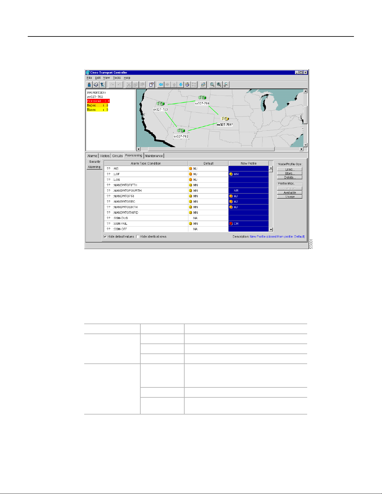
Figure 3-27 The Alarming tab showing the default profile and a new profile
AlarmProfiles are created at the network view using the Provisioning> Alarming tabs (Figure 3-27).
A default alarm profile (in the Default column) is pre-provisioned and you use the Clone feature to
create new profiles based on the default alarm profile.
The Alarming tab shows the default profile and the new profile. It also has two headings,
Node/Profile Ops and Profile Misc, which include six alarm profile buttons. Table 3-15 lists and
describes each of the alarm profile buttons.
Table 3-15 Alarm Profile Buttons
Heading Button Description
Node Profile Ops Load Loads a profile from either a node or a file
Store Stores profiles to a node (or nodes) or to a file
Delete Deletes profiles from a node
Profile Misc. Compare Displays differences between alarm profiles (i.e.
individual alarms that are not configured
equivalently between profiles)
Available Displays all of the profiles available on each node
Usage Displays all of the entities present in the network
and which profile(s) each is using
Five additional alarm profile options are located in a Profile Editing menu that you can display with
a right-click in any column that contains an alarm profile. Table 3-16 lists and describes the profile
editing options available when you right-click an alarm profile column.
Cisco ONS 15327 User Documentation 3-45
Page 46

3 Using Cisco Transport Controller 78-11719-02 July 2001
Table 3-16 Alarm Profile Editing Options
Button Description
Store Loads a profile from either a node or a file
Rename Changes a profile name
Clone Creates a new profile that contains the same alarm severity settings as
the highlighted profile (the profile being cloned)
Reset Restores a profile to the state of that profile before it was last applied or
to the state when it was first loaded, if it has not yet been applied
Remove Removes a profile from the table editor
Alarm severity is changed/assigned using a menu. Toviewthis menu, right-click the alarm you want
to change in its alarm profile column. Seven alarm severity levels appear:
• CR: Critical alarm
• MJ: Major alarm
• MN: Minor alarm
• NR: Not reported
• NA: Not alarmed
• TR: Transparent alarm
• UN: Unset alarm
Transparent and unset alarms are associated only with alarm profiles and therefore do not appear
when you view alarms, history, or conditions.
In addition to the alarm profile tabs, the Alarming tab displays two check boxes at the bottom of the
screen: Hide default values and Hide identical rows. The Hide default values check box will be
blank if the severity for that alarm is the same as the default. The Hide identical rows check box
allows you to hide rows that contain the same severity in each profile.
Procedure: Create an Alarm Profile
Step 1 Display the CTC network view.
Step 2 Click the Provisioning > Alarming tabs.
Step 3 Right-click anywhere in the Default column to display the Profile Editing menu.
Step 4 Choose Clone from the menu.
Step 5 In the Clone Profile Default dialog box, enter a name in New Profile Name.
Profile names must be unique. If you try to import or name a profile that has the same
name as another profile, CTC attempts to find an alternate name by adding a suffix.
Step 6 Click OK.
The new profile (named in Step 5) is created. It is identical to the default profile and is
added as a new column on the far right-hand side.
Step 7 Modify (customize) the alarm profile:
(a) In the new alarm profile column, click in a row that contains the alarm severity you
want to change.
Cisco ONS 15327 User Documentation3-46
Page 47

78-11719-02 July 2001 Using Cisco Transport Controller 3
(b) From the menu, select the desired severity.
(c) Repeat Steps a and b for each alarm that needs to be changed.
(d) After you haveassigned the properties to your new alarm profile, click the Store tab.
(e) In the Store Profile(s) dialog box, select a node or nodes where the profile will be
stored and/or specify a file on the workstation.
(f) Click OK.
Procedure: Apply an Alarm Profile at the Card View
Step 1 In CTC, display the card view of the desired DS-N card (the DS-N ports are located on
the XTC card).
Step 2 Click the Provisioning > (DS1 or DS3) Alarming tabs.
Step 3 To apply profiles on a port-to-port basis:
(a) Click the appropriate row under the Profile column for the port desired.
(b) Choose the appropriate profile.
(c) Click Apply. (Multiple port profiles can be selected before clicking Apply.)
Step 4 To set a profile for all the ports on a card:
(a) Click the Force all ports to profile menu arrow at the bottom of the screen.
(b) Choose the appropriate profile.
(c) Click Force (still need to “Apply”)
(d) Click Apply.
Tip If you choose the wrong profile, click Reset to return to the previous profile setting.
Procedure: Apply an Alarm Profile at the Node View
Step 1 In CTC, display the node view.
Step 2 Click the Provisioning > Alarming tabs.
Step 3 To apply profiles on a card basis:
(a) Click the Profile column for the card desired.
(b) Choose the appropriate profile.
(c) Click Apply. (Multiple card profiles can be selected before clicking Apply.)
Step 4 To apply the profile to an entire node:
(a) Click the Node Profile menu arrow.
(b) Choose the appropriate profile.
(c) Click Apply.
Cisco ONS 15327 User Documentation 3-47
Page 48

3 Using Cisco Transport Controller 78-11719-02 July 2001
Note The Port Overrides column at the node viewreads true when additional profiles are available
and false when only the inherited profile is available.
Tip If you choose the wrong profile, click Reset to return to the previous profile.
3.14 Printing and Exporting CTC Data
You can print CTC windows and CTC data that displays in columns, such as alarms and inventory.
You can also export CTC table data in formats that can be used by other applications such as
spreadsheets, word processors, and database management applications. Table 3-17 shows the CTC
data that you can export.
Table 3-17 Exportable CTC Table Data
View Tab Subtab
Node Alarms
History Node/Session
Circuits
Provisioning Ether Bridge/Network (Static Routes)/Alarming
Inventory
Maintenance Ether Bridge/Software/Audit/Routing Table
Network Alarms
History
Circuits
Provisioning Security (Print Only)/Alarming
Maintenance Software
OC Cards Alarms
History Session/Card
Circuits
Provisioning Line/Threshold/Alarming
Maintenance Loopback/Protection (print only)
Performance
Ethernet
Cards
Alarms
History
Circuits
Provisioning Port/VLAN/Card (print only)/Alarming
Performance Statistics/Utilization/History
Cisco ONS 15327 User Documentation3-48
Page 49

78-11719-02 July 2001 Using Cisco Transport Controller 3
Table 3-17 Exportable CTC Table Data (continued)
View Tab Subtab
XTC Cards Alarms
History Session/Card
Circuits
Provisioning DS1 Alarming/DS3 Alarming/External
Maintenance
Performance DS1/DS3
Procedure: Print CTC Data
Use the followingprocedure to print CTC screens and data. Before you start, make sure your PC is
connected to a printer.
Step 1 From the File menu on the menu bar, click Print.
Step 2 In the Print dialog box (Figure 3-28), choose an option:
• Entire Frame—Prints the entire CTC window
• Tabbed View—Prints the lower half of the CTC window
• TableContents—Prints CTCdata in table format; this option is only available for CTC
Figure 3-28 Printing the CTC window
Step 3
Step 4 In the Windows Print dialog box, choose a printer and click Print.
Procedure: Export CTC Data
Step 1 From the File menu, click Export.
Click OK.
table data (see Table 3-17)
Step 2 In the Export dialog box (Figure 3-29), choose an option:
• As HTML—Saves the data as an HTML file. The file can be viewed with a web
browser without running CTC.
• As CSV—Saves the CTC table values as text, separated by commas. You can import
CSV data into spreadsheets and database management programs.
Cisco ONS 15327 User Documentation 3-49
Page 50
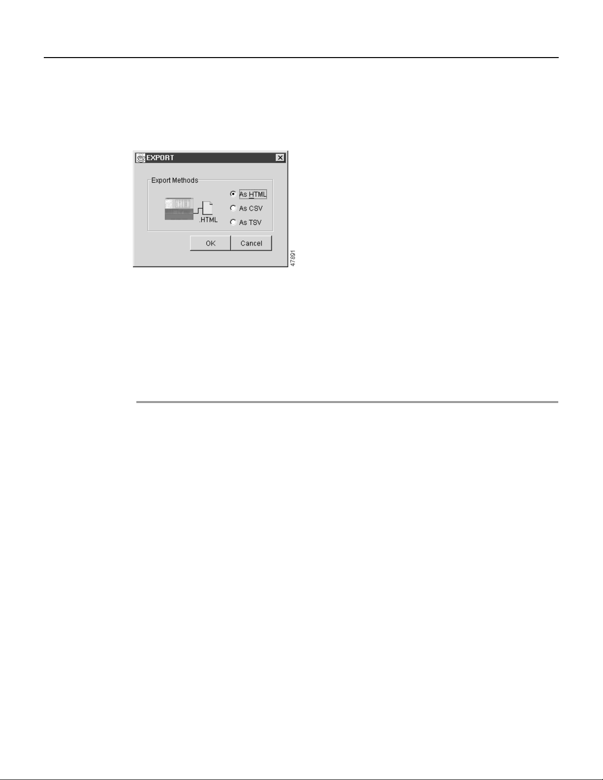
3 Using Cisco Transport Controller 78-11719-02 July 2001
• As TSV—Saves the CTC table values as text, separated by tabs. You can import TSV
data into spreadsheets and database management programs.
Figure 3-29 Exporting CTC data as HTML
Step 3
Step 4 In the Save dialog box, enter a file name in one of the following formats:
Click OK.
• [filename].htm for HTML files.
• [filename].csv for CSV files.
• [filename].tsv for TSV files.
Step 5 Navigate to a directory where you will store the file.
Step 6 Click OK.
3.15 Displaying CTC Data in Other Applications
You can display CTC data exported in HTML with any web browser application, such as Netscape
or Microsoft Internet Explorer. To display the data, use the web browser’s File/Open command to
open the CTC data file.
You can display CTC data exported as comma separated values(CSV) or tab separated values (TSV)
in text editors, word processors, spreadsheets, and database management applications. Although
procedures depend on the application, you can typically use File/Open to display the CTC data. Text
editors and word processors display the data exactly as it is exported. Spreadsheet and database
management applications display the data in cells. You can format and manage the data using the
spreadsheet or database management application tools.
Cisco ONS 15327 User Documentation3-50
 Loading...