

Page 1

Cisco ONS 15327 Troubleshooting Guide
Product and Documentation Release 3.4
April 2003
Corporate Headquarters
Cisco Systems, Inc.
170 West Tasman Drive
San Jose, CA 95134-1706
USA
http://www.cisco.com
Tel: 408 526-4000
800 553-NETS (6387)
Fax: 408 526-4100
Customer Order Number: DOC-7815641=
Text Part Number: 78-15641-01
Page 2

THE SPECIFICATIONS AND INFORMATION REGARDING THE PRODUCTS IN THIS M ANUAL ARE SUBJECT TO CHA NGE WITHOUT NO TICE. ALL
STATEMENTS, INFORMATION, AND RECOMMENDATIONS IN THIS MANUAL ARE BELIEVED TO BE ACCURATE BUT ARE PRESENTED WITHOUT
WARRANTY OF ANY KIND, EXPRESS OR IMPLIED. USERS MUST TAKE FULL RESPONSI BILITY FOR THEIR APPLICA TION OF ANY PRODUCT S.
THE SOFTWARE LICENSE AND LIMITED WARRANTY FOR THE ACCOMPANYING PRODUCT ARE SET FORT H IN THE INFORMATION PACKET T HAT
SHIPPED WITH THE PRODUCT AND ARE INCORPORATED HEREIN BY THIS REFERENCE. IF YOU ARE UNABLE TO LOCATE THE SOFTWARE LICENSE
OR LIMITED WARRANTY, CONTACT YOUR CISCO REPRESENTATIVE FOR A COPY.
The following information is for FCC compliance of Class A devices: This equipment has been tested and found to comply with the limits for a Class A digital device, pursuant
to part 15 of the FCC rules. These limits are designed to provide reasonable protection against harmful interference when the equipment is operated in a commercial
environment. This equipment generates, uses, and can radiate radio-frequency energy and, if not installed and used in accordance with the instruction manual, may cause
harmful interference to radio communications. Operation of this equipment in a residential area is likely to cause harmful interference, in which case users will be required
to correct the interference at their own expense.
The following information is for FCC compliance of Class B devices: The equipment described in this manual generates and may radiate radio-frequency ener gy. If it is not
installed in accordance with Cisco’s installation instructions, it may cause interference with radio and television reception. This equipment has been tested and found to
comply with the limits for a Class B digital device in accordance with the specifications in part 15 of the FCC rules. These specifications are designed to provide reasonable
protection against such interference in a residential installation. However, there is no guarantee that interference will not occur in a particular installation.
Modifying the equipment without Cisc o’s writ ten author ization m ay resul t in the equi pment no lo nger comp lyi ng with FCC requi rements for Class A or Class B digital
devices. In that event, your right to use the equ ipment may be limit ed by FCC regul ations , and you may be requir ed to correct a ny interference to radio or television
communications at your own expense.
You can determine whether your equipment is causing interference by turning it off. If the interferen ce stops, it was probably caused by the Cis co equipm ent or one of its
peripheral devices. If the equipment causes interference to radio or television reception, try to correct the interference by using one or more of the following measures:
• Turn the television or radio antenna unt il the int erference st ops.
• Move the equipment to one side or the other of the televisio n or radi o.
• Move the equipment farther away from the te levision or radio.
• Plug the equipment into an outlet that is on a di fferent cir cuit from the televi sion o r radio. (That is, make certain th e equipment and the te levision or radio are on circuit s
controlled by different circuit breaker s or fuses.)
Modifications to this product no t author ized by Cis co Syst ems, Inc. coul d voi d the FCC appro val and ne gate your authorit y to op erate the pr oduct.
The Cisco implementation of TCP head er compressi on is an adap tation of a program developed by the Universi ty of Ca lifornia, Berk eley (UCB) as part of UCB ’s public
domain version of the UNIX operatin g system. All rights reserved . Copyri ght © 1981 , Rege nts of the Uni versity of Calif ornia.
NOTWITHSTANDING ANY OTHER WARRANTY HEREIN, ALL DOCUMENT FILES AND SOFTWARE OF THE SE SUPPLIERS ARE PROVIDED “AS IS” WITH
ALL FAULTS. CISCO AND THE ABOVE-NAMED SUPPLIERS DISCLAI M ALL WARRANTIE S, EXPRESSED OR IMPLIED, INCLUDING, WITHOUT
LIMITATION, THOSE OF MERCHANTABILITY, FITNESS FOR A PARTICULAR PURPOSE AND NO NINFRINGEM ENT OR ARISING FROM A COURS E OF
DEALING, USAGE, OR TRADE PRACTICE.
IN NO EVENT SHALL CISCO OR ITS SUPPLIERS BE LIABLE FOR ANY INDIRECT, SPECIAL, CONSEQUENTIAL, OR INCIDENTAL DAMAGES, INCLUDING ,
WITHOUT LIMITATION, LOST PROFITS OR LOSS OR DAMAGE TO DATA ARISING OUT OF THE USE OR INABILITY TO USE THIS MANUAL, EVEN IF CISCO
OR ITS SUPPLIERS HAVE BEEN ADVISED OF THE POSSIBILITY OF SUCH DAMAGE S.
CCIP, CCSP, the Cisco Arrow logo, the Cisco Powered Network mark, Cisco Unity, Follow Me Browsing, FormShare, and StackWise are trademarks of Cisco Systems, Inc.;
Changing the Way We Work, Live, Play, and Learn, and iQuick Study are service marks of Cisco Systems, Inc.; and Aironet, ASIST, BPX, Catalyst, CCDA, CCDP, CCIE, CCNA,
CCNP, Cisco, the Cisco Certified Internetwork Expert logo, Cisco IOS, the Cisco IOS logo, Cisco Press, Cisco Systems, Cisco Systems Capital, the Cisco Systems logo,
Empowering the Internet Generation, Enterprise/Solver, EtherChannel, EtherSwitch, Fast Step, GigaStack, Internet Quotient, IOS, IP/TV, iQ Expertise, the iQ logo, iQ Net
Readiness Scorecard, LightStream, MGX, MICA, the Networkers logo, Networking Academy, Network Registrar, Packet, PIX, Post-Routing, Pre-Routing, RateMUX, Registrar,
ScriptShare, SlideCast, SMARTnet, StrataView Plus, Stratm, SwitchProbe, TeleRouter, The Fastest Way to Increase Your Internet Quotient, TransPath, and VCO are registered
trademarks of Cisco Systems, Inc. and/or its affiliates in the United States and certain other countries.
All other trademarks mentioned in this document or Website are the property of their respective owners. The use of the word partner does not imply a partnership relationship
between Cisco and any other company. (0401R)
Cisco ONS 15327 Troubleshooting Guide
Copyright © 2003 Cisco Systems, Inc. All rights reserved.
Page 3

About this Guide xxi
Document Objectives xxi
Audience xxi
Related Documentation xxi
Document Conventions xxii
Where to Find Safety and Warning Information xxiii
Obtaining Documentation xxiii
Cisco.com xxiii
Documentation CD-ROM xxiii
Ordering Documentation xxiv
Documentation Feedback xxiv
Obtaining Technical Assistance xxiv
Cisco.com xxiv
Technical Assistance Center xxv
Cisco TAC Website xxv
Cisco TAC Escalation Center xxvi
CONTENTS
CHAPTER
Obtaining Additional Publications and Information xxvi
1 General Troubleshooting 1-1
1.1 Network Troubleshooting Tests 1-2
1.2 Ident if y Points of Failur e on a DS-N Circuit Path 1-4
1.2.1 Perform a Facility Loopback on a Source XTC Port 1-5
Create the Facility Loopback on the Source XTC Port 1-5
Test the Facilit y Loo pb ack 1-6
Test the DS-N Cab ling 1-6
Test the XTC Ca rd 1-7
Test the MIC Cabl ing 1-7
Test the MIC Card 1-8
1.2.2 Perform a Hairpin on a Source Node XTC Port 1-8
Create the Hairpin on the Source Node Port 1-9
Test the Hairpin Circuit 1-9
Test the Altern ate Source XTC Card 1-10
Retest the Original Source XTC Card 1-11
1.2.3 Perform a Terminal Loopback on a Destination XTC Port 1-11
April 2003
Cisco ONS 15327 Troubleshooting Guide, R3.4
iii
Page 4

Contents
Create the Terminal Loopback on a Destination XTC Port 1-12
Test the Terminal Loopback Circuit on the Destination XTC Port 1-13
Test the Destination XTC Card 1-14
1.2.4 Per form a Hairpin on a Destination No d e XT C Port 1-14
Create the Hairpin Loopback Circuit on th e Destination Node XTC Card 1-15
Test the Hairpin Circuit 1-16
Test the Altern a te De stination XTC Ca rd 1-16
Retest the Original Destination XTC Card 1-17
1.2.5 Perform a Facility Loopback on a Destination XTC Card 1-18
Create a Facility Loopback Circuit on a Destination XTC Port 1-18
Test the Facilit y Loo pb ack Circuit 1-19
Test the DS-N Cab ling 1-19
Test the XTC Ca rd 1-20
Test the MIC Card 1-20
1.3 Identify Points of Failure on an OC-N Circuit Path 1-21
1.3.1 Perform a Facility Loopback on a Source-N ode OC-N Port 1-21
Create the Facil ity Loopback on the Source OC-N Port 1-22
Test the Facilit y Loo pb ack Circuit 1-22
Test the OC-N Car d 1-23
1.3.2 Perform a Cross-Connect Loopback on the Source OC-N Port 1-23
Test the Cross -C onnect Loopb a ck Circuit 1-24
Test the Standby XTC Card 1-25
Retest the Original XTC Card 1-26
1.3.3 Perform a Terminal Loopback on a Source-Node OC-N Port 1-27
Create the Terminal Loopback on a Source Node OC- N Port 1-27
Test the Terminal Loopback Circuit 1-28
Test the OC-N Car d 1-29
1.3.4 Perform a Facility Loopback on an Interm ediate-Node OC-N Port 1-29
Create the Facility Loopback on an Interm ediate-Node OC-N Port 1-30
Test the Facilit y Loo pb ack Circuit 1-31
Test the OC-N Car d 1-32
1.3.5 Perform a Terminal Loopback on an Intermediate-Node OC-N Port 1-32
Create the Terminal Loopback on an Intermedi ate-Node OC-N Port 1-33
Test the Terminal Loopback Circuit 1-34
Test the OC-N Car d 1-34
1.3.6 Perform a Facility Loopback on a Destination-Node OC-N Port 1-35
Create the Facility Loopback on a Destinati on Node OC-N Port 1-36
Test the Facilit y Loo pb ack Circuit 1-37
Test the OC-N Car d 1-37
1.3.7 Perform a Terminal Loopback on a Destination Node OC-N Port 1-38
iv
Cisco ONS 15327 Troubleshooting Guide, R3.4
April 2003
Page 5

Create the Terminal Loopback on a Destination Node OC-N Port 1-39
Test the Termi na l Lo o pback Circuit 1-40
Test the OC-N Car d 1-40
1.4 Restoring the Database and Default Settings 1-41
1.4.1 Res t ore the Node Data ba se 1-41
Restore the Databa se 1-41
1.4.2 Res t ore the Node to Fact ory Configura ti on 1-43
Use the Reinitialization Tool to Clear t he Database and Upload Software (Windows) 1-43
Use the Reinitiali zation Tool to Clear the Database and Upload Software (UNIX) 1-45
1.5 PC Connectivity Troubleshooting 1-47
1.5.1 Unable to Verify the IP Configuration of Your PC 1-47
Verify the IP Configuration of Your PC 1-47
1.5.2 Browser Login Does Not Launch Java 1-48
Reconfigur e th e PC Operating Sy st em Ja v a Plug-in Contr ol Panel 1-48
Reconfigur e th e B ro w se r 1-48
1.5.3 Unable to Verify the NIC Connection on Your PC 1-49
1.5.4 Verify PC Connection to the ONS 15327 (Ping) 1-50
Ping the ONS 15327 1-50
1.5.5 The IP Address of the Node is Unknown 1-51
Retrieve Unknown Node IP Address 1-51
Contents
1.6 CTC Operation Troubleshooting 1-52
1.6.1 Unable to Launch CTC Help After Removing Netscape 1-52
Set Internet Explorer as the Default Brow ser for CTC 1-52
1.6.2 Unable to Change Node View to Network View 1-52
Reset the CTC_HEAP Environment Variable for Windows 1-53
Reset the CTC_HEAP Environment Variable for Solaris 1-53
1.6.3 Browser Stalls When Downloading CTC JAR Files from XTC 1-54
Disable the VirusScan Download Scan 1-54
1.6.4 CTC D oe s N ot Launch 1-54
Redirect the Netscape Cache to a Valid Directory 1-55
1.6.5 Sluggish CTC Operation or Login Proble ms 1-55
Delete the CTC Cache File Automatically 1-55
Delete the CTC Cache File Manually 1-56
1.6.6 Node Icon is Gray on CTC Network View 1-57
1.6.7 CTC Cannot Launch Due to Applet Security Restrictions 1-57
Manually Edit the ja va .p o lic y Fi le 1-58
1.6.8 Java Runtime Environment Incompatible 1-58
Launch CTC to Correct the Core Version Build 1-59
1.6.9 Different CTC Releases Do Not Recognize Each Other 1-59
April 2003
Cisco ONS 15327 Troubleshooting Guide, R3.4
v
Page 6

Contents
Launch CTC to Correct the Core Version Build 1-60
1.6.10 Username or Password Does Not Match the XTC Information 1-60
Verify Correc t U se rn a m e an d Pas s w or d 1-61
1.6.11 No IP Connectivity Exists Between Nodes 1-61
1.6.12 DCC Connection Lost 1-61
1.6.13 “Path in Use” Error When Creating a Circuit 1-61
Cancel the Circuit Creation and Start Over 1-62
1.6.14 Calculate and Design IP Subnets 1-62
1.6.15 Et hernet Conne c tio n s 1-62
Verify Ethernet Connections 1-63
1.6.16 VLAN Cannot Connect to Network Device from Untag Port 1-64
Change VLAN Port Tag and Untagged Settings 1-65
1.7 Circu it s an d Tim in g 1-66
1.7.1 Circuit Transitions to Partial State 1-66
View the State of Circuit Nodes 1-67
1.7.2 AIS-V on XTC-28-3 Unused VT Circuits 1-67
Clear AIS-V on XTC-28-3 Unused VT Circuits 1-67
1.7.3 Circuit Creati on Error with VT1.5 Circuit 1-68
1.7.4 DS 3 Ca r d Does Not Report AIS-P From Extern al Equipmen t 1-68
1.7.5 OC-3 and DCC Limitati ons 1-69
1.7.6 ONS 15327 Switches Timing Reference 1-69
1.7.7 Holdover Synchr onization Alarm 1-70
1.7.8 Free-Running Synchronization Mode 1-70
1.7.9 Daisy-Chaine d BITS Not Functioning 1-70
1.7.10 Blinking STAT LED after Installing a Card 1-71
vi
1.8 Fiber and Cabling 1-71
1.8.1 Bit Erro r s Appear for a Traffic Card 1-71
1.8.2 Fau lt y Fiber-Optic Co nn e ct i o ns 1-72
Verify Fiber-O ptic Connections 1-72
1.8.2.1 Crimp Replacement LAN Cables 1-74
1.8.2.2 R ep lace Faulty SFP Co nnectors 1-76
Remove SFP Connectors 1-76
Install SFP Connectors 1-76
1.8.2.3 Optical Card Transmit and Receive Levels 1-77
1.9 Power and LED Tests 1-78
1.9.1 Power Supply Prob lems 1-78
Isolate the Cau s e of Pow e r S up ply Problems 1-79
1.9.2 Power Consumpt ion for Node and Cards 1-79
1.9.3 Lamp Test for Card LEDs 1-80
Cisco ONS 15327 Troubleshooting Guide, R3.4
April 2003
Page 7

Verify Card LED Operation 1-80
Contents
CHAPTER
2 Alarm Troubleshooting 2-1
2.1 Alarm In de x by D ef au lt Sev e rity 2-1
2.1.1 Critical Alarms (CR) 2-1
2.1.2 Maj o r A la rm s (M J) 2-2
2.1.3 Mi no r A la rm s (MN ) 2-2
2.1.4 Conditions (NA or NR) 2-3
2.2 Alarms and Conditions Indexed By Alphabet ical Entry 2-4
2.3 Alarm Index by Alarm Type 2-6
2.3.1 Ala rm Ty p e/ O bject Definit io n 2-13
2.4 Trouble Notifications 2-14
2.4.1 Conditions 2-14
2.4.2 Severities 2-14
2.5 Safety Summary 2-15
2.6 Alarm Procedures 2-15
2.6.1 AIS 2-16
Clear the AIS Condition 2-16
2.6.2 AIS-L 2-16
Clear the AIS-L Condition 2-16
2.6.3 AIS-P 2-17
Clear the AIS-P Cond ition 2-17
2.6.4 AIS-V 2-17
Clear the AIS-V Cond ition 2-17
2.6.5 APSB 2-18
Clear the APSB Alarm 2-18
2.6.6 APSCDFLTK 2-18
Clear the APSCDFLTK Alarm 2-19
2.6.7 APSC-IMP 2-19
Clear the APSC-IMP Alarm 2-20
2.6.8 APSCINCON 2-20
Clear the APSCINCON Alarm 2-20
2.6.9 APSCM 2-21
Clear the APSCM Alarm 2-21
2.6.10 APSCNMIS 2-21
Clear the APSCNMIS Alarm 2-21
2.6.11 APSMM 2-22
Clear the APSMM Alarm 2-22
2.6.12 AS-CMD 2-23
April 2003
Cisco ONS 15327 Troubleshooting Guide, R3.4
vii
Page 8

Contents
Clear the AS-CMD Condition 2-23
2.6.13 AS-MT 2-23
Clear the AS-MT Condi tion 2-24
2.6.14 AUD-LOG-LOSS 2-24
Clear the AUD-LOG-LOSS Condition 2-24
2.6.15 AUD-LOG-LOW 2-24
2.6.16 AUTORESET 2-25
Clear the AUTORESET Ala rm 2-25
2.6.17 AUTOSW-AIS 2-25
Clear the AUTOSW-AIS Condition 2-25
2.6.18 AUTOSW-LOP (STSMON) 2-26
Clear the AUTOSW-LOP (STSMON) Condition 2-26
2.6.19 AUTOSW-LOP (VTMON) 2-26
Clear the AUTOSW-LOP (VTMON) Alarm 2-26
2.6.20 AUTOSW-PDI 2-26
Clear the AUTOSW-PDI Condition 2-26
2.6.21 AUTOSW-SDBER 2-27
Clear the AUTOSW-SDBER Con dition 2-27
2.6.22 AUTOSW-SFBER 2-27
Clear the AUTOSW-SFBER Condition 2-27
2.6.23 AUTOSW-UNEQ (STSMON) 2-27
Clear the AUTOSW-UNEQ (STSMON) Condition 2-27
2.6.24 AUTOSW-UNEQ (VTMON) 2-28
Clear the AUTOSW-UNEQ (VTMON) Al arm 2-28
2.6.25 BAT-A-HGH-VLT 2-28
Clear the BAT-A-HGH-VLT Condition 2-28
2.6.26 BAT-A-LOW-VLT 2-28
Clear the BAT-A-LOW-VLT Co ndition 2-28
2.6.27 BAT-B-HGH-VLT 2-29
Clear the BAT-B-HGH-VLT Condition 2-29
2.6.28 BAT-B-LOW-VLT 2-29
Clear the BAT-B-LOW-VLT Condition 2-29
2.6.29 BKUPMEMP 2-29
Clear the BKUPMEMP Alarm 2-30
2.6.30 BLSROSYNC 2-30
Clear the BLSROSYNC Alarm 2-30
2.6.31 CA R L O SS (EQPT) 2-31
Clear the CARLOSS (EQPT) Alarm 2-31
2.6.32 C A R L O SS (E Series) 2-32
Clear the CARLOSS (E-Series) Alarm 2-32
viii
Cisco ONS 15327 Troubleshooting Guide, R3.4
April 2003
Page 9

2.6.33 CA R L O SS (G Se rie s ) 2-33
Clear the CARLOSS (G Serie s) Alarm 2-34
2.6.34 CLDRESTART 2-36
Clear the CLDRESTART Co ndition 2-36
2.6.35 COMIOXC 2-37
Clear the COMIOXC Alarm 2-37
2.6.36 CONTBUS-A-18 2-37
Clear the CONTBUS-A-18 Alarm 2-37
2.6.37 CONTBUS-B-18 2-38
Clear the CONTBUS-B-18 Al arm 2-38
2.6.38 CONTBUS-IO-A 2-38
Clear the CONTBUS-IO-A Alarm 2-39
2.6.39 CONTBUS-IO-B 2-40
Clear the CONTBUS-IO-B Al arm 2-40
2.6.40 CTNEQPT-PBPROT 2-41
Clear the CTNEQPT-PBPROT Alarm 2-42
2.6.41 CTNEQPT-PBWORK 2-43
Clear the CTNEQPT-PBWORK Alarm 2-43
2.6.42 DATAFLT 2-44
Clear the DATAFLT Alarm 2-44
2.6.43 DBOSYNC 2-45
Clear the DBOSYNC Alarm 2-45
2.6.44 DS3-MISM 2-45
Clear the DS3-MISM Condition 2-46
2.6.45 EHIBATVG-A 2-46
Clear the EHIBATVG-A Alar m 2-46
2.6.46 EHIBATVG-B 2-46
Clear the EHIBATVG-B Alarm 2-47
2.6.47 ELWBATVG-A 2-47
Clear the ELWBATVG-A Alarm 2-47
2.6.48 ELWBATVG-B 2-47
Clear the ELWBATVG-B Alarm 2-47
2.6.49 EOC 2-48
Clear the EOC Alarm 2-48
2.6.50 EQPT 2-50
Clear the EQPT Alarm 2-50
2.6.51 EQPT-MISS 2-51
Clear the EQPT-MISS Alarm 2-51
2.6.52 E-W-MISMATCH 2-51
Clear the E-W-MISMATCH Alarm with a Physical Switch 2-52
Contents
April 2003
Cisco ONS 15327 Troubleshooting Guide, R3.4
ix
Page 10

Contents
Clear the E-W-MISMATCH Alarm in CT C 2-52
2.6.53 EXCCOL 2-53
Clear the EXCCOL Alarm 2-53
2.6.54 EXERCISE-RING-REQ 2-53
2.6.55 EXERCISE-SPAN-REQ 2-53
2.6.56 EXT 2-54
Clear the EXT Alarm 2-54
2.6.57 EXTRA-TRAF-PREEMPT 2-54
Clear the EXTRA-TRAF-PREEMPT Alarm 2-54
2.6.58 FAILTOSW 2-54
Clear the FAILTOSW Condition 2-55
2.6.59 FAILTOSW-PATH 2-55
Clear the FAILTOSW-PATH Condition in a UPSR Configuration 2-55
2.6.60 FAILTOSWR 2-56
Clear the FAILTOSWR Condition in a BLSR Configuration 2-56
2.6.61 FAILTOSWS 2-58
Clear the FAILTOSWS Condition 2-58
2.6.62 FAN 2-59
Clear the FAN Alarm 2-60
2.6.63 FANDEGRADE 2-60
Clear the FANDEGRADE Alarm 2-60
2.6.64 FE-AIS 2-60
Clear the FE-AIS Condition 2-60
2.6.65 FE-DS1-MULTLOS 2-61
Clear the FE-DS1-MUL TLOS Condition 2-61
2.6.66 FE-DS1-NSA 2-61
Clear the FE-DS1-NSA Condition 2-61
2.6.67 FE-DS1-SA 2-62
Clear the FE-DS1-SA Condition 2-62
2.6.68 FE-DS1-SNGLLOS 2-62
Clear the FE-DS1-SNGLLOS Condition 2-62
2.6.69 FE-DS3-NSA 2-63
Clear the FE-DS3-NSA Condition 2-63
2.6.70 FE-DS3-SA 2-63
Clear the FE-DS3-SA Condition 2-63
2.6.71 FE-EQPT-NSA 2-64
Clear the FE-EQPT-NSA Condition 2-64
2.6.72 FE-EXERCISING-RING 2-64
2.6.73 FE-EXERCISING-SPAN 2-64
2.6.74 FE-FRCDWKSWPR-RING 2-65
Cisco ONS 15327 Troubleshooting Guide, R3.4
x
April 2003
Page 11

Clear the FE-FRCDWKSWPR-RING Condition 2-65
2.6.75 FE-FRCDWKSWPR-SPAN 2-65
Clear the FE-FRCDWKSWPR-SPAN Condition 2-65
2.6.76 FE-IDLE 2-66
Clear the FE-IDLE Co ndition 2-66
2.6.77 FE-LOCKOUTOFPR-SPAN 2-66
Clear the FE-LOCKOUTOFPR-SPAN Condition 2-66
2.6.78 FE-LOF 2-67
Clear the FE-LOF Condition 2-67
2.6.79 FE-LOS 2-67
Clear the FE-LOS Cond ition 2-67
2.6.80 FE-MANWKSWPR-RING 2-68
Clear the FE-MANWKSWPR-RING Condition 2-68
2.6.81 FE-MANWKSWPR-SPAN 2-68
Clear the FE-MANWKSWPR-SPAN Condition 2-68
2.6.82 FEPRLF 2-69
Clear the FEPRLF Alarm on a BLSR 2-69
2.6.83 FORCED-REQ 2-69
Clear the FORCED-REQ Condition 2-69
2.6.84 FORCED-REQ-RING 2-69
Clear the FORCED-REQ-RING Condition 2-70
2.6.85 FORCED-REQ-SPAN 2-70
Clear the FORCED-REQ-SPAN Condition 2-70
2.6.86 FRCDSWTOINT 2-70
2.6.87 FRCDSWTOPRI 2-70
2.6.88 FRCDSWTOSEC 2-71
2.6.89 FRCDSWTOTHIRD 2-71
2.6.90 FRNGSYNC 2-71
Clear the FRNGSYNC Alarm 2-71
2.6.91 FSTSYNC 2-71
2.6.92 FULLPASSTHR-BI 2-72
Clear the FULLPASSTHR-BI Condition 2-72
2.6.93 HITEMP 2-72
Clear the HITEMP Alarm 2-72
2.6.94 HLDOVRSYNC 2-73
Clear the HLDOVRSYNC Alarm 2-73
2.6.95 IMPROPRMVL 2-73
Clear the IMPROPRMVL Alarm 2-74
2.6.96 INC-ISD 2-75
2.6.97 INHSWPR 2-75
Contents
April 2003
Cisco ONS 15327 Troubleshooting Guide, R3.4
xi
Page 12

Contents
Clear the INHSWPR Condition 2-75
2.6.98 INHSWWKG 2-75
Clear the INHSWWKG Condition 2-76
2.6.99 INVMACADR 2-76
2.6.100 KB-PASSTHR 2-76
Clear the KB-PASSTHR Condition 2-76
2.6.101 LKOUTPR-S 2-76
Clear the LKOUTPR-S Co ndition 2-76
2.6.102 LOCKOUT-REQ 2-77
Clear the LOCKOUT-REQ Condition 2-77
2.6.103 LOCKOUT-REQ-RING 2-77
Clear the LOCKOUT-REQ-RING Condition 2-77
2.6.104 LOF (BITS) 2-77
Clear the LOF (BITS) Al arm 2-78
2.6.105 LOF (DS-1) 2-78
Clear the LOF (DS-1) Alarm 2-78
2.6.106 LOF (DS-3) 2-79
Clear the LOF (DS-3) Alarm 2-79
2.6.107 LOF (OC-N) 2-80
Clear the LOF (OC-N) Alarm 2-80
2.6.108 LOP-P 2-80
Clear the LOP-P Alarm 2-81
2.6.109 LOP-V 2-81
Clear the LOP-V Alarm 2-81
2.6.110 LOS (BITS) 2-81
Clear the LOS (BITS) Al arm 2-82
2.6.111 LOS (DS-1) 2-82
Clear the LOS (DS-1) Alarm 2-82
2.6.112 LOS (DS-3) 2-83
Clear the LOS (DS-3) Alarm 2-83
2.6.113 LOS (OC-N) 2-84
Clear the LOS (OC-N) Alar m 2-85
2.6.114 LPBKCRS 2-86
Clear the LBKCRS Condition 2-86
2.6.115 LPBKFACILITY (D S -N ) 2-86
Clear the LPBKFACILITY (DS-N) Condition 2-86
2.6.116 LPBKFACILI TY (O C -N ) 2-87
Clear the LPBKFACILITY (OC-N) Condition 2-87
2.6.117 LPBKTERMIN A L (D S -N , O C- N ) 2-87
Clear the LPBKTERMINAL (DS-N, OC-N) Condition 2-87
xii
Cisco ONS 15327 Troubleshooting Guide, R3.4
April 2003
Page 13

2.6.118 LPBKTERM IN A L (G-S e ri es ) 2-88
Clear the LPBKTERMINAL (G-Series) Condition 2-88
2.6.119 MAN-REQ 2-88
Clear the MAN-REQ Condition 2-88
2.6.120 MANRESET 2-88
2.6.121 MANSWTOINT 2-89
2.6.122 MANSWTOPRI 2-89
2.6.123 MANSWTOSEC 2-89
2.6.124 MANSWTOTHIRD 2-89
2.6.125 MANUAL-REQ-RING 2-89
Clear the MANUAL-REQ-RING Condition 2-90
2.6.126 MANUAL-REQ-SPAN 2-90
Clear the MANUAL-REQ-SPAN Condition 2-90
2.6.127 MEA (EQPT) 2-90
Clear the MEA (EQPT) Alar m 2-90
2.6.128 MEM-GONE 2-91
2.6.129 MEM-LOW 2-92
2.6.130 MFGMEM 2-92
Clear the MFGMEM (BP, Fan-Tray Assembly) Alarm 2-92
2.6.131 PDI-P 2-93
Clear the PDI-P Condition 2-93
2.6.132 PEER-NORESPONSE 2-94
Clear the PEER-NORESPONSE Alarm 2-94
2.6.133 PLM-P 2-95
Clear the PLM-P Alarm 2-95
2.6.134 PLM-V 2-96
Clear the PLM-V Alarm 2-96
2.6.135 PRC-DUPID 2-96
Clear the PRC-DUPID Alarm 2-96
2.6.136 PROTNA 2-97
Clear the PROTNA Alarm 2-97
2.6.137 PWR-A 2-98
Clear the PWR-A Alarm 2-98
2.6.138 PWR-B 2-99
Clear the PWR-B Alarm 2-99
2.6.139 PWR-REDUN 2-100
Clear the PWR-REDUN Alarm 2-100
2.6.140 RAI 2-100
Clear the RAI Conditi on 2-100
2.6.141 RCVR-MISS 2-100
Contents
April 2003
Cisco ONS 15327 Troubleshooting Guide, R3.4
xiii
Page 14

Contents
Clear the RCVR-MISS Alar m 2-101
2.6.142 RFI-L 2-101
Clear the RFI-L Con dition 2-101
2.6.143 RFI-P 2-102
Clear the RFI-P Con dition 2-102
2.6.144 RFI-V 2-102
Clear the RFI-V Condition 2-103
2.6.145 RING-MISMATCH 2-103
Clear the RING-MISMATCH Alarm 2-103
2.6.146 RING-SW-EAST 2-104
2.6.147 RING-SW-WEST 2-104
2.6.148 SD 2-104
Clear the SD Condition 2-105
2.6.149 SD-L 2-105
Clear the SD-L Conditi on 2-105
2.6.150 SD-P 2-105
Clear the SD-P Condition 2-106
2.6.151 SF 2-106
Clear the SF Condition 2-106
2.6.152 SF-L 2-106
Clear the SF-L Condition 2-107
2.6.153 SF-P 2-107
Clear the SF-P Condition 2-107
2.6.154 SFTWDOWN 2-107
2.6.155 SNTP-HOST 2-108
Clear the SNTP-HOST Alarm 2-108
2.6.156 SPAN-SW-EAST 2-108
2.6.157 SPAN-SW-WEST 2-108
2.6.158 SQUELCH 2-109
Clear the SQUELCH Condition 2-109
2.6.159 SSM-DUS 2-110
2.6.160 SSM-FAIL 2-110
Clear the SSM-FAIL Alarm 2-110
2.6.161 SSM-LNC 2-111
2.6.162 SSM-OFF 2-111
Clear the SSM-OFF Condition 2-111
2.6.163 SSM-PRC 2-111
2.6.164 SSM-PRS 2-111
2.6.165 SSM-RES 2-112
2.6.166 SSM-SMC 2-112
xiv
Cisco ONS 15327 Troubleshooting Guide, R3.4
April 2003
Page 15

2.6.167 SSM-ST2 2-112
2.6.168 SSM-ST3 2-112
2.6.169 SSM-ST3E 2-112
2.6.170 SSM-ST4 2-113
2.6.171 SSM-STU 2-113
Clear the STU Condition 2-113
2.6.172 SSM-TNC 2-113
2.6.173 SWMTXMOD 2-113
Clear the SWMTXMOD Alarm 2-114
2.6.174 SWTOPRI 2-115
2.6.175 SWTOSEC 2-115
Clear the SWTOSEC Conditi on 2-115
2.6.176 SWTOTHIRD 2-115
Procedure: Clear th e SWTOTHIRD Condition 2-116
2.6.177 SYNC-FREQ 2-116
Clear the SYNC-FREQ Condition 2-116
2.6.178 SYNCPRI 2-117
Clear the SYNCPRI Alarm 2-117
2.6.179 SYNCSEC 2-117
Clear the SYNCSEC Alarm 2-117
2.6.180 SYNCTHIRD 2-118
Clear the SYNCTHIRD Alarm 2-118
2.6.181 SYSBOOT 2-119
2.6.182 TIM-P 2-119
Clear the TIM-P Alarm 2-119
2.6.183 TPTFAIL (G-Series) 2-120
Clear the TPTFAIL (G-Series) Alarm 2-120
2.6.184 TRMT 2-120
Clear the TRMT Alarm 2-121
2.6.185 TRMT-MISS 2-121
Clear the TRMT-MISS Alarm 2-121
2.6.186 UNEQ-P 2-122
Clear the UNEQ-P Alarm 2-122
2.6.187 UNEQ-V 2-123
Clear the UNEQ-V Alarm 2-124
2.6.188 WKSWPR 2-124
Clear the WKSWPR Condition 2-124
2.6.189 WTR 2-124
Contents
April 2003
2.7 XTC Li ne Ala rms 2-124
2.8 Common Procedures in Alarm Troubleshooting 2-125
Cisco ONS 15327 Troubleshooting Guide, R3.4
xv
Page 16

Contents
Identify a Ring ID or Node ID Number 2-125
Change a Ring ID Number 2-125
Change a Node ID Number 2-126
Verify Node Vi si bility for Other No de s 2-126
Verify or Create Node DCC Terminations 2-126
Lock Out a BLSR Span 2-127
Clear a BLSR Span Lock Out 2-127
Clear a UPSR Lock Out 2-127
Switch Protection Group Traffic with an External Switching Command 2-127
Clear an External Switching Command 2-128
Delete a Circuit 2-128
Clear a Loopback 2-128
Reset the Active XTC Card in CTC 2-129
Reset a Traffic Card in CTC 2-129
Verify BER Threshold Level 2-129
Physically Replace a Card 2-130
Remove and Rei ns e rt (R es e at) a Card 2-130
Remove and Reinsert Fan-Tray Assembly 2-130
CHAPTER
I
NDEX
3 Replace Hardware 3-1
3.1 Replace the Fan-Tray Assembly 3-1
3.2 Remove and Reinsert (Reseat) the Standby XTC 3-3
3.3 Inspect, Clean, and Replace the Reusable Air Filter 3-3
xvi
Cisco ONS 15327 Troubleshooting Guide, R3.4
April 2003
Page 17

Figure 1-1 Facility Loopback Process on an XTC Card 1-2
Figure 1-2 Facility Loopback Process on an OC-N Card 1-2
Figure 1-3 Terminal Loopback Process on an OC-N Card 1-3
Figure 1-4 Terminal Loopback Process on a G1000-2 Card 1-3
Figure 1-5 Hairpin Circuit Process on an OC-N Card 1-3
Figure 1-6 Cross-Connect Loopback Process on an OC-N Port 1-4
Figure 1-7 Facility Loopback on a Source XTC Port 1-5
Figure 1-8 Hairpin Circuit on a Source Node XTC Port 1-9
Figure 1-9 Terminal Loopback on a Destination XTC Port 1-12
Figure 1-10 Hairpin on a Destination Node XTC Card 1-15
Figure 1-11 Facility Loopback on a Destination XTC Card 1-18
Figure 1-12 Facility Loopback on a Circuit Source OC-N Po rt 1-22
Figure 1-13 Cross-Connect Lo opback on a Source OC-N Port 1-24
Figure 1-14 Terminal Loopback on a Source-Node OC-N Port 1-27
Figure 1-15 Facility Loopback on an Intermediate-Node OC-N Port 1-30
FIGURES
Figure 1-16 Terminal Loopback on an Intermediate-Node OC-N Port 1-33
Figure 1-17 Facility Loopback on a Destination Node OC-N Port 1-35
Figure 1-18 Terminal Loopback on a Destination Node OC-N Port 1-38
Figure 1-19 Reinitialization Tool in Windows 1-44
Figure 1-20 Confirm NE Restoration 1-45
Figure 1-21 Reinitialization Tool in UNIX 1-46
Figure 1-22 Deleting the CTC Cache 1-56
Figure 1-23 Ethernet Connectivity Reference 1-63
Figure 1-24 VLAN with Ethernet Ports at Tagged and Untag 1-64
Figure 1-25 Configuring VLAN Membership for Individu al Ethernet Ports 1-65
Figure 1-26 RJ-45 Pin Numbers 1-74
Figure 1-27 LAN Cable Layout 1-74
Figure 1-28 Cross-Over Cable Layout 1-75
Figure 3-1 Removing the Fan-Tray Assembly 3-2
Figure 3-2 Replacing the Fan-Tray Assembly 3-2
Figure 3-3 Removing the Reusable Fan-Tray Air Filter 3-4
April 2003
Cisco ONS 15327 Troubleshooting Guide, R3.4
xvii
Page 18

Figures
Figure 3-4 Replacing the Reusable Fan-Tray Air Filter 3-5
xviii
Cisco ONS 15327 Troubleshooting Guide, R3.4
April 2003
Page 19

Table 1-1 Restore the Node Data base 1-41
Table 1-2 Restore the Node to Factory Configuration 1-43
Table 1-3 Unable to Verify the I P Configuration of Your PC 1-47
Table 1-4 Browser Logi n Do es No t La un c h Ja va 1-48
Table 1-5 Unable to Verify the NI C Connection on Your PC 1-49
Table 1-6 Verify PC Connection to ONS 15327 (Ping) 1-50
Table 1-7 Retrieve the Unknown IP Address of the Node 1-51
Table 1-8 Unable to Launch CTC Help After Removing Netscape 1-52
Table 1-9 Browser Stalls When Downloading Files From XTC 1-53
Table 1-10 Browser Stalls When Downloading JAR File from XTC 1-54
Table 1-11 CTC Does Not Launch 1-54
Table 1-12 Sluggish CTC Operation or Login Problems 1-55
Table 1-13 Node Icon is Gray on CTC Network View 1-57
Table 1-14 CTC Cannot Launch Due to Applet Security Restrictions 1-57
Table 1-15 Java Runtime Environment In co m p at ible 1-58
TABLES
Table 1-16 JRE Compatibility 1-59
Table 1-17 Different CTC Releases Do Not Recognize Each Other 1-60
Table 1-18 Username or Password Does Not Match the XTC Information 1-60
Table 1-19 No IP Connectivity Exists Between Nodes 1-61
Table 1-20 DCC Connection Lost 1-61
Table 1-21 “Path in Use” Error When Creating a Circuit 1-62
Table 1-22 Calculate and Design IP Subnets 1-62
Table 1-23 Ethernet Connections 1-63
Table 1-24 VLAN Cannot Connection to Network Device from Untag Port 1-65
Table 1-25 Circuit in Partial State 1-66
Table 1-26 AIS-V on XTC-28-3 Unused VT Circuits 1-67
Table 1-27 Circuit Creati o n Er ro r w ith VT 1 .5 Circ u i t 1-68
Table 1-28 DS3 Card Does Not Report AIS-P From External Equipment 1-69
Table 1-29 OC-3 and DCC Limitations 1-69
Table 1-30 ONS 15327 Switches Timing Reference 1-69
Table 1-31 Holdover Synchronization Alarm 1-70
April 2003
Cisco ONS 15327 Reference Manual, R3.4
xix
Page 20

Tables
Table 1-32 Free-Running Synchronization Mode 1-70
Table 1-33 Daisy-Chained BITS Not Functioning 1-70
Table 1-34 Blinking STAT LED on Installed Card 1-71
Table 1-35 Bit Errors Appear for a Line Card 1-71
Table 1-36 Faulty Fiber-O ptic Connections 1-72
Table 1-37 LAN Cable Pinout 1-75
Table 1-38 Cross-Over Cable Pinout 1-75
Table 1-39 Available SFP Conn ectors 1-76
Table 1-40 Optical Card Tran smit and Receive Levels 1-77
Table 1-41 Power Supply Problems 1-78
Table 1-42 Power Consumption for Node and Cards 1-79
Table 1-43 Lamp Test for Card LEDs 1-80
Table 2-1 Critical Alarm Index 2-1
Table 2-2 Major Alarm Index 2-2
Table 2-3 Minor Alarm Index 2-2
Table 2-4 Conditions Index 2-3
Table 2-5 Alphabetical Alarm Index 2-4
Table 2-6 Alarm Index by Alarm Type 2-6
Table 2-7 Alarm Type/ Ob ject Definition 2-13
Table 2-8 DS3-12E Line Alarms 2-125
xx
Cisco ONS 15327 Reference Manual, R3.4
April 2003
Page 21

About this Guide
This section expla ins the obje ctives, inten ded a ud ienc e, an d o rganiza tio n of th is pu bl icat ion an d
describes the conventions that convey instructions and other information.
This section provides the following information:
• Document Objectives
• Audience
• Related Documentation
• Document Conventions
• Obtaining Documentation
• Where to Find S afe ty a nd Warning Informati on
• Obtaining Technical Assistance
• Obtaining Additional Publications and Information
Document Objectives
The Cisco ONS 15 327 Troubleshooting Guide provides trou blesh ooti ng pr oc ed ures for SON ET a la rms
and error message s and p rovid es sym pt oms and solut ion s f or gene ral tro uble shoo tin g p robl ems wit h
CTC and hardware. T hi s guide al so co nt ain s h ard ware re pla c emen t pr oc ed ures. U se thi s d ocum ent i n
conjunction with the appropriate publications listed in the Related Documentation section.
Audience
To use this publication, you should be familia r with Cisc o or equivalent optical transmi ssion har dware
and cabling, te lec om mu nicat ions ha rdware an d c a bling, e lec tro ni c ci rcu itr y an d w iri ng pra cti ces, a nd
preferably have experience as a tele commu nic ations techn icia n.
Related Documentation
Use this Cisco ONS 15327 Troubleshooting Guide in conjunction with the following referenced
publications:
April 2003
Cisco ONS 15327 Troubleshooting Guide, R3.4
xxi
Page 22

Document Conventions
• Cisco ONS 15327 P rocedure Guide, Release 3.4
Provides installation, turn up, provisioni ng, and ma intainenc e proce dures for Cisco O NS 15327
nodes and networks
• Cisco ONS 15327 Refe rence Manual, Releas e 3.4
Provides reference information including detailed card specifications, feature descriptions, and
topology informatio n
• Cisco ONS 15454 a nd Cisco ON S 15 327 TL1 Comm and G uid e, Re lease 3.4
Provides a comprehensive list of TL1 commands for the ONS 153 27 and ONS 15454
• Release Notes fo r the C i sco O NS 15327 Release 3.4
Provides up-to-date caveats, closed issues, and new feature information
Document Conventions
This publication uses the following conventions:
Convention Application
About this Guide
boldface Commands and keywords in b ody t ext.
italic Command input that is supplied by the user.
[ ] Keywords or arguments that appear within square brackets are optional.
{ x | x | x } A choice of keywords (represented by x) appears in braces separated by
vertical bars. The user must select one.
Ctrl The control key. For example, where Ctrl + D is written, hold down the
Control key while pressing the D key.
screen font Examples of in forma ti on displa yed o n t h e scr e en.
boldface screen font Examples of information that the user must enter.
< > Command paramete rs tha t mu st be r epl ace d by m odu le- spe cific co de s.
Note Means reader take note. Notes contain helpful suggestions or references to material not covered in the
document.
xxii
Caution Means reader be careful. In this situation, the user might do something that could result in equipment
damage or loss of data.
Cisco ONS 15327 Troubleshooting Guide, R3.4
April 2003
Page 23

About this Guide
Where to Find Safety and Warning Information
Warning
IMPORTANT SAFETY INSTRUCTIONS
This warning symbol means danger. You are in a situation that could cause bodily injury. Before you
work on any equipment, be aware of the hazards involved with electrical circuitry and be familiar
with standard practices for preventing accidents. To see translations of the warnings that appear in
this publication, refer to the translated safety warnings that accompanied this device.
Note: SAVE THESE INSTRUCTIONS
Note: This documentation is to be used in conjunction wit h the specif ic product instal lation guide
that shipped with the product. Please refer to the Installation Guide, Configuration Guide, or other
Where to Find Safety and Warning Inf ormation
For safety and warning information, refer to the Cisco ONS 15327 In stall ation Ha ndbook that
accompanied the product. This publication describes the international agency compliance and safety
information for the Cisco ONS 15327. It also includes translations of the safety warnings that appear in
the ONS 15327 sy stem do cu ment ation .
Obtaining Documentation
Cisco provides several ways to obtain documentation, techn ical assistance , and other tec hnical
resources. These sect ion s expla in h ow to obta in te chni cal infor ma tion fr om Ci sco Sy stem s.
Cisco.com
You can access the most c ur rent C isco doc um entat ion on the World Wide Web at this URL:
http://www.cisco.com/univercd/home/home.htm
You can access the Cisco website at this URL:
http://www.cisco.com
International Cisco websites can be accessed from this URL:
http://www.cisco.com/public/countries_languages.shtml
Documentation CD-ROM
Optical networking-re lated doc umen tation is available in a CD-ROM package that shi ps with yo ur
product. The Optical Networking Product Documentation CD-ROM is updated periodically and may be
more current than printed documentation.
April 2003
Cisco ONS 15327 Troubleshooting Guide, R3.4
xxiii
Page 24

Obtaining Technical As sistance
Ordering Documentation
You can find instructions for or de ring do cu ment atio n a t t his U RL:
http://www.cisco.com/univercd/cc/td/doc/es_inpck/pdi.htm
You can order Cisco documentation in these ways:
• Registered Cisco.com users (Cisco direct customers) can order Cisco product documentation from
the Networking Produ cts Market Pla ce:
http://www.cisco.com/en/US/partner/ordering/index.shtml
• Nonregistered Cisco.co m u ser s can o rd er docum en tati on th rou gh a l oc al ac count r epre sen tative by
calling Cisco Systems Corpo rate Headqu arter s (Califo rnia, U.S.A. ) at 408 526-7208 or, elsewhere
in North America, by calli ng 800 55 3-NE TS (6387).
Documentation Feedback
You can submit comments electronic ally on Cisco.c om . On the C isco Doc ume nta tion home pag e, cli ck
Feedback at the top of the page.
You can e-mail your comments to bug-d oc@cisc o.com.
About this Guide
You can submit comments by using the respon se card (i f present ) behind t he front cover of your
document or by wri ting t o the fo llowing a ddress:
Cisco Systems
Attn: Customer Docume nt Ordering
170 West Tasman Drive
San Jose, CA 95134- 988 3
We appreciate yo ur comm ents .
Obtaining Technical Assistanc e
Cisco provides Cisco.com , w hich incl udes the Ci sco Technical Assistance Cent er ( TAC) website, as a
starting point for all technical assistance. Customers and partners can obtain online documentation,
troubleshooting tips, and sample configurations from the Cisco T AC website. Cisco.com registered users
have complete access to the technical support resources on the Cisco TAC website, including TAC tools
and utilities.
Cisco.com
Cisco.com offers a suite of in tera ct ive, networked serv ices t hat le t y ou acc ess Ci sco in for mat ion,
networking solutions, services, pr ogram s, and re sources at any time, from anywhe re in the world.
xxiv
Cisco.com provides a br oad r ange of fea tur es an d s er vice s to h elp you wi th th ese ta sks:
• Streamline business processes and improve productivity
• Resolve technical issues with online support
• Download and te st so ft war e pa ck ag es
• Order Cisco learning m ateri als and me rcha ndise
Cisco ONS 15327 Troubleshooting Guide, R3.4
April 2003
Page 25

About this Guide
• Register for online skill assessment, training, and certification programs
To obtain customized information and service, you can self-register on Cisco.com at this URL:
http://tools.cisco.com/RPF/register/register.do
Technical Assistance Center
The Cisco TAC is available to all customers who need technical assistance with a Cisco product,
technology, or solution. Two types of support are available: the Ci sco TAC website and the Cisco TAC
Escalation Center. The type of support that you choose depends on t he priorit y of the proble m and the
conditions stated in service contracts, when applicable.
We categorize Cisco TAC inquiries according to urgency:
• Priority level 4 (P4)—You need information or assistance conc erni n g Cisc o pr odu ct c apa bil ities,
product installation, or basic product configuration. There is little or no impact to yo ur business
operations.
• Priority level 3 (P3)—Operational performance of the network is impaired, but most business
operations remain functional. You and Cisco are willing to commit resou rces during normal bu siness
hours to restore service to satisfactory levels.
Obtaining Technical Assistance
Cisco TAC Website
The Cisco TAC website provides online documents and tools to help troubleshoot and resolve technical
issues with Cisco products and technologies. To access the Cisco TAC website, go to this URL:
http://www.cisco.com/tac
All customers, partners, and resellers who have a valid Cisco service contract have complete access to
the technical support resources on the Cisco TAC website. Some services on the Cisco TAC website
require a Cisco.co m login ID and password. If you have a valid service contract but do not have a login
ID or password, go t o th is URL to register :
http://tools.cisco.com/RPF/register/register.do
If you are a Cisco.com registere d user, and you cannot resol ve your tech ni cal issues by using the Cisco
TAC website, you can open a case online at this URL:
http://www.cisco.com/tac/caseopen
If you have Internet acc ess , we re com mend tha t y ou open P3 and P4 case s onl ine so that y ou ca n fu lly
describe the situation and attach any necessary files.
• Priority level 2 (P2)—Operation of an existing network is severely degraded, or significant aspects
of your business operations are negatively impacted by inadeq ua te pe rform an ce of Cisc o pro duct s.
You and Cisco will c ommit full-time resource s during normal busi ness hours to resolv e the situation.
• Priority level 1 (P1)—An existing network is “down,” or there is a critical impact to your business
operations. You and Cisco will commit all necessary resources around the clock to resolve the
situation.
April 2003
Cisco ONS 15327 Troubleshooting Guide, R3.4
xxv
Page 26

Obtaining Additiona l Publications and Informatio n
Cisco TAC Escalation Center
The Cisco TAC Escalation Center addresses priority level 1 or priority level 2 issues. These
classifications are assigned when severe network degradation significantly impacts business operations.
When you contact the TAC Escalation Center with a P1 or P2 problem, a Cisco TAC engineer
automatically opens a case.
To obtain a dir ect ory o f t oll-fr ee C isco TAC telephone n umb er s f or yo ur co unt ry, go to this URL:
http://www.cisco.com/warp/public/687/Directory/DirTAC.shtml
Before calling, please check with your network operations center to d etermine the Cisco support services
to which your company is en title d: fo r example, SMARTnet, SMARTnet Onsite, or Netw ork Suppor te d
Accounts (NSA). When you call the center, please have available your service agreement number and
your product seria l nu mb er.
Obtaining Additional Publications and Information
Information about Cisco products, technologies, and network solutions is available from various online
and printed sources.
About this Guide
• The Cisco Product Catalog describes the networking products offered by Cisco Systems, as well as
ordering and custome r support ser vices. Access the Cisco Product Catalog at this URL:
http://www.cisco.com/en/US/products/products_catalog_links_launch.html
• Cisco Press publishes a wid e ran ge of n etworki ng pub l icatio ns. Cisco suggest s the se t itle s for new
and experienced users: Internetworking Terms and Acronyms Dictionary, Internetworking
Technology Handbook, Int ernet wo rkin g Troubleshooting Guide, and the Inter netw ork ing De sign
Guide. For current Cisco Press titles and other information, go to Cisco Press online at this URL:
http://www.ciscopress.com
• Packet magazine is the Cisco quart erly pub licatio n that provides the latest networki ng trend s,
technology breakthrough s, and Cisco products an d solutions t o help ind ustry professi onals ge t the
most from their networking investment. Included are networking depl oyment an d troublesho oting
tips, configuration e xamples, customer case studies, tutorials and train ing, certificatio n information,
and links to numerous in-de pth online resour ces. You can access Packet ma gazine at this U RL:
http://www.cisco.com/go/packet
• iQ Magazine is the Cisco bimonthl y publica tion that de livers the latest informat ion about Int ernet
business strategies for executives. You can access i Q Magazi ne at th is UR L:
http://www.cisco.com/go/iqmagazine
• Internet Protocol Journa l is a quarterly jour nal publ ished by Cisco Systems for engineering
professionals involved in designing, developing, and ope ratin g p ubli c a nd pr ivate internets a nd
intranets. You can access the Internet Protocol Journal at this URL:
http://www.cisco.com/en/US/about/ac123/ac147/about_cisco_the_internet_protocol_journal.html
xxvi
• Training—Cisco offers world-class networking t raining. Curren t offerings in network tra ining are
listed at this URL:
http://www.cisco.com/en/US/learning/le31/learning_recommended_training_list.html
Cisco ONS 15327 Troubleshooting Guide, R3.4
April 2003
Page 27

CHAPTER
1
General Troubleshooting
This chapter provides proce dures for trouble shooting the most co mmon pro blems enc ounte red when
operating a Cisco ONS 153 27. To troubleshoot specific ONS 15327 alarms, see Chapter 2, “Alarm
Troubleshooting.” If you cann ot find wha t yo u ar e l ookin g f or cont act th e Ci sco Technical Assistance
Center (Cis co TAC).
This chapter includ es the fo llowing sec tions on network pr oble ms:
• 1.1 Network Troubleshoo tin g Tests—Describes loopbac ks and hair pin circui ts, whic h you can use
to test circuit paths through the network or logically isolate faults.
Note For network acceptance tests, refer to the Cisco ONS 15327 Procedure Guide.
• 1.2 Identify Points of Failure on a DS-N Circuit Path—Describes the steps to perform loopback and
hairpin tests, which y ou c an us e t o te st D S-N cir cuit path s t hrough th e n etwork o r l ogic al ly is olate
faults.
• 1.3 Identify Points of Failure on an OC-N Circuit Path—Describes the st eps to perf orm lo opbac k
and hairpin tests, which you can use to test OC-N ci rcuit pa ths through th e network or log ically
isolate faults.
April 2003
The remaining sections describe symptoms, problems, and solutions that are categorized according to
the following topics:
• 1.4 Restoring the Da tabase and D efault Se tting s—P rovides procedu res for re storing soft ware data
and restoring the n ode to t he d efaul t se tup.
• 1.5 PC Conne ctivity Troubleshooting— Provides troubl eshooting pr ocedure s for PC and network
connectivity to the ONS 15327.
• 1.6 CTC Operation Troubleshoot ing—Provide s tro ubles hoot ing pro cedu res f or CTC l ogin o r
operation problems.
• 1.7 Circui ts a nd Timing—Provides tro ubleshoo ting pro cedure s for cir cuit crea tion an d error
reporting as well as timi ng refere nce erro rs and alar ms.
• 1.8 Fiber a nd Cabl ing—Pr ovides tr ouble sho oti ng pro cedu re s f or fiber a nd cab ling c on nectivity
errors.
Cisco ONS 15327 Troubleshooting Guide, R3.4
1-1
Page 28
Network Troubleshooting Tests
1.1 Network Troubleshooting Tests
Use loopbacks and hairpins to te st ne wly created cir cuits before run ning li ve tra ff ic or to logically loca te
the source of a network failure. All ONS 15327 line (traffic) cards, except Ethernet cards, allow
loopbacks and ha irpins.
Caution On OC-N cards, a facility loopback applies to the entire card and not an individual circuit. Exercise
caution when using loop ba ck s o n an O C-N ca rd c arryi ng live traffic.
A facility loopback tests the line interface unit (LIU) of a card, the mechanical interface card (MIC), and
related cabling. After applyin g a facility loopback on a port, use a test set to run traffi c over the loopb ack.
A successful facility loopback isolates the LI U, th e M IC, o r the cab lin g pla nt as the po tential cause of a
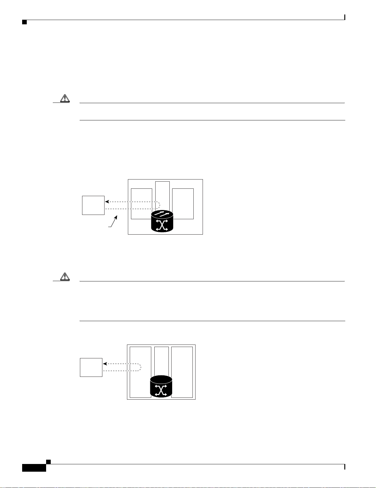
network problem. Figure 1-1 shows a facility loopback on an XTC-14 or XTC-28-3 ca rd.
Figure 1-1 Facility Loopback Process on an XTC Card
XTC
Test Set A
DS-N
MIC OC-N
Chapter1 General Troubleshooting
DS-N
Facility
loopback
76186
To test the LIU on an OC-N card, connect an optical test set to the OC-N port and perform a facility
loopback or use a loopback or hairpin on a card that is farther along the circuit path. Figur e 1-2 shows a
facility loopback on an OC-N card.
Caution Before performing a facilit y loop ba ck on a n OC -N c ard, m ake sur e the car d co ntain s at le ast two da ta
communications channel (DCC) paths to the node where the card is installed. A second DCC provides
a nonlooped path to log into the node after the loopback is applied, thus enabling you to remove the
facility loopback. Ensuring a second DCC is not necessary if you are directly connected to the
ONS 15327 conta ining the l oopback OC-N car d.
Figure 1-2 Facility Loopback Process on an OC-N Card
OC-N OC-NXTC
Test Set
1-2
90642
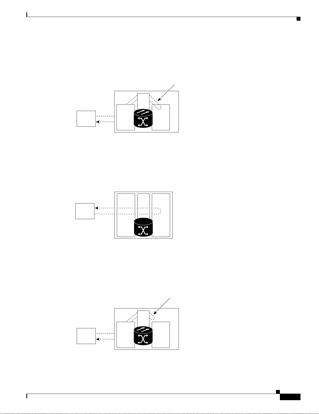
A terminal loopback tests a circuit path as it passes through t he XTC card and loops back from the card
with the loopback. Figure 1-3 on page 1- 3 shows a terminal loopback on an OC-N card. The test-set
traffic comes in on the MIC card DS-N ports and goes through the XTC card to the OC-N card. The
Cisco ONS 15327 Troubleshooting Guide, R3.4
April 2003
Page 29
Chapter 1 General Troubleshooting
terminal loopback on the OC-N card turns the signal around before it reaches the LIU and sends it back
through the XTC card to the MIC card. This test verifies that the XTC card cross-connect circuit paths
are valid, but does not test the LIU on the OC-N card.
Figure 1-3 Terminal Loopback Process on an OC-N Card
Network Troubleshooting Tests
Terminal loopback
XTC
Test Set A
DS-N
MIC OC-N
DS-N
76191
Figure 1-4 shows a terminal loopback on a G1000-2 card. The test-set traffic comes in on the MIC card
DS-N ports and g oe s t hroug h th e X TC car d to t he G 10 00-2 c a rd. T he te rmi nal loop ba ck on the
G1000-2 card turns the signal around before it r ea ches the LIU and sends it back thr ough the XTC card
to the MIC card. This test verifies that the XTC card cross-connect circuit paths are valid, but does not
test the LIU on the G1000 -2 card.
Figure 1-4 Terminal Loopback Process on a G1000-2 Card
MIC
XTC
G1000-2
Test Set
90641
A hairpin circui t br ings tra ffic in and ou t on a D S-N por t i nste ad o f se nd ing the tra ffic onto the OC -N .
A hairpin loops back only the specific STS or VT circuit and does not cause an entire OC-N port to loop
back, which would drop all traffic on the OC-N port. Th e hairpi n allows you to test a ci rcu it on nodes
running live traffic. Figure 1-5 shows the hairpin circuit proc ess on a OC-N car d.
April 2003
Figure 1-5 Hairpin Circuit Process on an OC-N Card
Hairpin circuit
XTC
Test Set A
DS-N
MIC OC-N
DS-N
76193
Cisco ONS 15327 Troubleshooting Guide, R3.4
1-3
Page 30
Identify Points of Failure on a DS-N Circuit Path
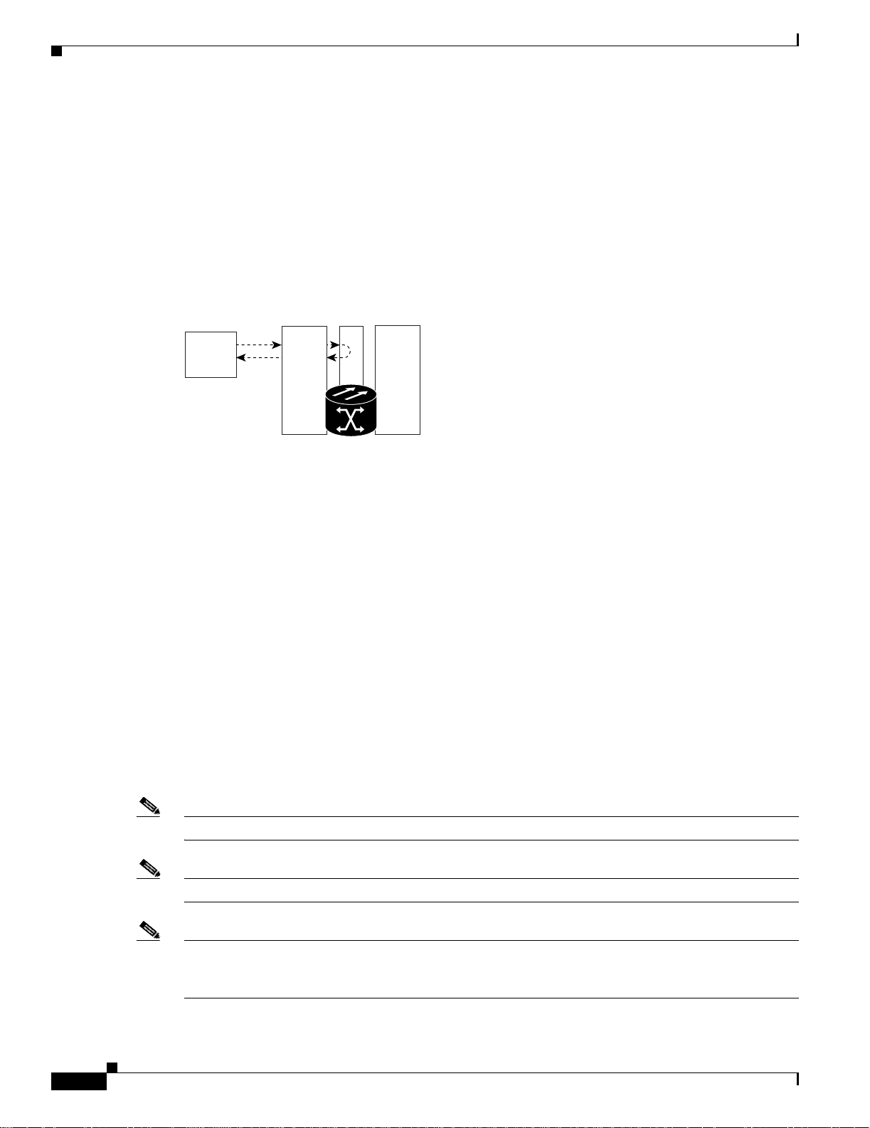
A cross-connect loopback tests a circuit path as it passes through the cross-connect card and loops back
to the port being tested. Testing and verifying circuit integrity often involves taking down the whole line;
however, a cross-conne ct lo opb ack all ows you to cr ea te a l oo pbac k o n a ny embe dd ed cha nne l a t
supported payloads at the STS-1 granularity and higher. For example, you can loop back a single STS-1,
STS-3c, STS-6c, etc., on an optical facility without interrupting the other STS circuits.
You can create a cross -c onn ect loo pba ck o n a ll worki ng or p rot ect opt ic al ports un less the pr ote ct p ort
is used in a 1+ 1 pro te ctio n g rou p and is in worki ng m ode. If a t e rmi nal or fac ilit y l oop back exi sts on a
port, you cannot use t he c ro ss-con nect lo opbac k. Figu re 1-6 shows a cross-connect loopback on an
OC-N port.
Figure 1-6 Cross-Connect Loopback Process on an OC-N Port
Test Set
OC-Nx
x
XTC
Chapter1 General Troubleshooting
OC-Ny
90645
1.2 Identify Points of Failure on a DS-N Circuit Path
Facility loopbacks, hairpin circuits, an d terminal loopba cks are often used to test a circu it path through
the network or to logically isolate a fault. Performing a loopback test at each point along the circuit path
systematically isolates possib le points of failure.
The example in this section tests an DS-N circuit o n a two-node bidirecti onal line switched ring (BLSR).
Using a series of facility loopback s, hai rpin circu its, and termin al loopb acks, the path of the circui t is
traced and the possible points of failure are tested and eliminated. A logical progression of network test
procedures applies to this scenario:
1. Facility loopback on t he s our ce -n ode X TC p ort
2. Hairpin on the source-nod e XTC port
3. Terminal loopback to the destinat ion-n ode XT C por t
4. Hairpin on the dest inat ion -no de X TC p ort
5. Facility loopback to the destination XTC port
Note The test seque nce for your c irc uits differs ac c ord ing to t he t y pe of c irc uit a nd net work t op ology.
Note All loopback tests require on-si te personne l.
1-4
Note These procedures are perfor med when power connecti ons to the nod e(s) or site (s) ar e assumed t o be
within necessary specificat ions. If the network t ests do not isolat e the pro blems, tro ubleshoo t outward
for power failure.
Cisco ONS 15327 Troubleshooting Guide, R3.4
April 2003
Page 31

Chapter 1 General Troubleshooting
Identify Points of Failure on a DS-N Circuit Path
1.2.1 Perform a Facility Loopback on a Source XTC Port
The facility loopback test is performed on the node source port in the network circuit; in this example,
the test is routed through the MIC card and performed on the XTC port in the source node. Completing
a successful facility loopback on this port isolates the cabling, MIC card, and XTC card as possible
failure points. Figure 1-7 shows an example of a facility loopback on a source node XTC port.
Figure 1-7 Facility Loopback on a Source XTC Port
ONS 15327
Source
XTC
Test Set A
Caution Performing a loopback on an in-service circuit is service-affecting.
Note Loopbacks operate only on ports in th e out of servic e-ma intenan ce (OO S_MT) state.
DS-N
DS-N
Facility loopback
MIC OC-N
OC-N MIC
Procedure: Create the Facility Loopback on the Source XTC Port
Step 1 Connect an electrical test set to the port you are testing.
Use appropriate cabling to att ach th e transmit ( Tx) and receive (Rx) terminals o f the e lectric al test set to
the MIC card, which interfaces with th e XTC card. Both T x and Rx connect to the sa me port. Adjust the
test set accordingly.
Step 2 Use CTC to create the facility loopback on the port b eing tested:
ONS 15327
Destination
XTC
76187
April 2003
a. In node view, double-click the ca rd whe re yo u a r e pe rfo rm ing the loop ba ck.
b. Click the Maintenance > Loopback tabs.
c. Choose OOS_MT from the State colum n for the port bein g tested . If thi s is a multiport card, select
the appropriate row for the port being tested.
d. Choose Facility (Line) from the Loopback Type column for the port being tested. If this is a
multiport card, select the appropriate row for the port being tested.
e. Click the Apply button.
f. Click the Yes button in the Confirmation Dialog box.
Note It is normal for a LPBKFACILITY condition to appear during loopback setup. The condition
clears when you remove the loopb ack.
Cisco ONS 15327 Troubleshooting Guide, R3.4
1-5
Page 32

Identify Points of Failure on a DS-N Circuit Path
Step 3 Proceed to the “Test the Facility Loopback” procedur e on page 1-6.
Procedure: Test the Facility Loopback
Step 1 If the test set is not already sending traffic, send test-set traffic on the loopback circuit.
Step 2 Examine the traffic received by the test set. Look for errors or any other signal information that the test
set is capable of indicating.
Step 3 If the test set indicates a good circuit, no further testing is necessary with the facility loopback:
a. Clear the loopback:
• Click the Maintenance > Loopback tabs.
• Choose None from the Lo opb ack Type column for the po rt bei ng t este d.
• Choose the appr opriat e state (IS, OOS, or OOS_A INS) fr om the Sta te colu mn for the port being
tested.
• Click the Apply butto n .
Chapter1 General Troubleshooting
• Click the Yes button in the Confirmation Dialog box.
b. Proceed to the “Perform a Cross-C onnec t L oop back on t he So urc e O C- N Por t” pro cedu re on
page 1-23.
Step 4 If the test set indicates a faulty circuit, the problem might be a faulty MIC card, faulty XTC card, or
faulty cabling from the DS-N port.
Step 5 Proceed to the “Test the DS-N Cabling” procedure on page 1-6.
Procedure: Test the DS-N Cabling
Step 1 Replace the suspect cabling (the cables from the test set to the MIC ports) with a cable known to be good.
If a cable known to be good is not available, test the suspect cable with a test set. Remove the suspect
cable from the MIC and connect the cable to the Tx and Rx terminals of the test set. Run traffic to
determine whether the cable is good or susp ect.
Step 2 Resend test-set traffic on the loopback circuit with a good cable installed.
Step 3 If the test set indicates a good circuit, the problem is probably the defective cable:
a. Replace the defective cable.
b. Clear the loopback:
• Click the Maintenance > Loopback tabs.
• Choose None from the Lo opb ack Type column for the po rt bei ng t este d.
1-6
• Choose the appr opriat e state (IS, OOS, or OOS_A INS) fr om the Sta te colu mn for the port being
tested.
• Click the Apply butto n .
• Click the Yes button in the Confirmation Dialog box.
Cisco ONS 15327 Troubleshooting Guide, R3.4
April 2003
Page 33

Chapter 1 General Troubleshooting
c. Proceed to the “Perform a Cross-C onnec t L oop back on t he So urc e O C- N Por t” pro cedu re on
page 1-23.
Step 4 If the test set indicates a faulty circuit, the problem might be a faulty card.
Step 5 Proceed to the “Test the XTC Card” procedure on page 1-7.
Procedure: Test the XTC Card
Step 1 Replace the suspect card with a card known to be good.
Step 2 Resend test traffic on the loopback circuit with a good card installed.
Step 3 If the test set indicates a good circuit, the problem is probably a defective card:
a. Return the defective card to Cisco through the returned materials authorization (RMA) process. Call
the Cisco TAC.
b. Replace the faulty card.
c. Clear the loopback:
Identify Points of Failure on a DS-N Circuit Path
• Click the Maintenance > Loopback tabs.
• Choose None from the Loopback Type column for the port being tested.
• Choose the appr opriat e state (IS, OOS, or OOS_A INS) fr om the Sta te colu mn for the po rt being
tested.
• Click the Apply butto n .
• Click the Yes button i n th e Con firmatio n Di al og box .
d. Proceed to the “Perform a Hairpin on a Source Node XTC Port ” proced ure on pag e 1- 8.
Step 4 If the test set indicates a fault circuit, the prob lem might be fau lty cabling fro m the MIC card to the XTC
card or a faulty MIC card.
Step 5 Proceed to the “Test the MIC Cabling” proced ure on pa ge 1- 7.
Procedure: Test the MIC Cabling
Step 1 Replace the suspect cabling (the cables from the test set to the MIC or from the MIC to the XTC) with
a cable that is kn own to be g ood .
If a good cable is not available, test the suspect cabl e with a test set. Rem ove the suspect cable and
connect the cable to the Tx and Rx terminals of the test set. Run traffic to determine whether the cable
is good or defec tive.
April 2003
Step 2 Resend test traffic on the loopback circuit with a cable that is known to be good installed.
Step 3 If the test set indicates a good circuit, the problem is probably the defective cable:
a. Replace the defective cable.
Cisco ONS 15327 Troubleshooting Guide, R3.4
1-7
Page 34

Identify Points of Failure on a DS-N Circuit Path
b. Clear the facility loopback:
• Click the Maintenance > Loopback tabs.
• Choose None from the Lo opb ack Type column for the po rt bei ng t este d.
• Choose the appr opriat e state (IS, OOS, or OOS_A INS) fr om the Sta te colu mn for the port being
tested.
• Click the Apply butto n .
• Click the Yes button in the Confirmation Dialog box.
c. Proceed to the “Perform a Hairpin on a Source Node XTC Port ” proced ure on pag e 1- 8.
Step 4 If the test set indicates a faulty circuit, the problem might be a faulty MIC card.
Step 5 Proceed to the “Test the MIC Card” procedur e on page 1-8.
Procedure: Test the MIC Card
Chapter1 General Troubleshooting
Step 1 Replace the suspe ct card with a good card. See the “Physically Replace a Card” procedure on page 2-130
for details.
Step 2 Resend test-set traffic on the loopback circuit with a good card installed.
Step 3 If the test set indicates a good circuit, the problem is probably a defective card:
a. Return the defective card to Cisco through the returned materials authorization (RMA) process. Call
the Cisco TAC.
b. Replace the faulty card. See the “Physically Replace a Card” p roce dure on page 2-130 for details.
c. Clear the loopback:
• Click the Maintenance > Loopback tabs.
• Choose None from the Lo opb ack Type column for the po rt bei ng t este d.
• Choose the appr opriat e state (IS, OOS, or OOS_A INS) fr om the Sta te colu mn for the port being
tested.
• Click the Apply butto n .
• Click the Yes button in the Confirmation Dialog box.
Step 4 If the test set indicates a faulty circuit, repeat all of the facility loopback procedures.
Step 5 Proceed to the “1.2.2 Perform a Hairpi n on a Sourc e N ode XT C Port ” se ctio n o n pag e 1-8.
1.2.2 Perform a Hairpin on a Source Node XTC Port
The hairpin test is performed on the first XTC card in the network circuit. A hairpin circuit uses the same
port for both source and destin ation. C ompleti ng a succes sful hair pin through t his card isolates th e
possibility that the source XTC card is the cause of the faulty circuit. Figure 1-8 on page 1-9 shows an
example of a hairp i n ci rcui t o n a sour ce n ode X TC por t.
Cisco ONS 15327 Troubleshooting Guide, R3.4
1-8
April 2003
Page 35

Chapter 1 General Troubleshooting
Figure 1-8 Hairpin Circuit on a Source Node XTC Port
Identify Points of Failure on a DS-N Circuit Path
ONS 15327
Source
XTC
Test Set A
Note An XTC card is required to ope rate the O NS 15327 and ca n be used in a redunda nt or nonre dundan t
DS-N
MIC OC-N OC-N MIC
DS-N
Hairpin
configuration.
Procedure: Create the Hairpin on the Source Node Port
Step 1 Connect an electrical test set to the port you are testing.
• If you just comp lete d th e “Perform a Facility Loopback on a Source XTC Port” procedure on
page 1-5, leave the e l ect ric al test set h ooked u p to th e M IC po rt.
• If you are st artin g t h e cu rrent pro ce du re w it hou t t he e lec tri cal test se t hooked u p t o the M IC port ,
use appropriate cabling to attach the Tx and Rx terminals of the electrical test set to the MIC
connectors for th e por t yo u a re testi ng. T he Tx an d R x te rm ina ls conn ect to the same p ort.
ONS 15327
Destination
XTC
76188
Adjust the test set accordingly.
Step 2 Use CTC to set up the hairpin on the port being tested:
a. Click the Circuits tab and click the Create button.
b. Give the circuit an easily identifiable name, such as Hairpin1.
c. Set the circuit Type and Size to the normal preferences.
d. Uncheck the Bidirectional check box and click th e Next button.
e. In the Circuit Source dialog box, select the same Node, card Slot, Port, and Type where the test set
is connected and c lic k t he Next bu t ton.
f. In the Circuit Destination dialog box, use the same Node, card Slot, Port, and Type used for the
Circuit Source dialog box a nd c lick the Finish but t o n .
Step 3 Confirm that th e newly crea ted ci rcu it appe ars on the Ci rcuit s tab li st as a on e- way c ircui t.
Step 4 Proceed to the “Test the Hairpin Circuit” proce dure on page 1-9.
Procedure: Test the Hairpin Circuit
Step 1 If the test set is not already sending traffic, send test-set traffic on the loopback circuit.
Step 2 Examine the test traffic received by the test set. Look for errors or any other signal information that the
test set is capable of indicating.
April 2003
Cisco ONS 15327 Troubleshooting Guide, R3.4
1-9
Page 36

Identify Points of Failure on a DS-N Circuit Path
Step 3 If the test set indicates a good circuit, no further testing is necessary with the hairpin loopback circuit:
a. Clear the hairpin circuit:
• Click the Circuits tab.
• Choose the hairpin circuit being tested.
• Click the Delete butto n .
• Click the Yes button in the Delete Circuits dialog box.
• Confirm that the hairpin circuit is deleted from the Circuits tab list.
b. Proceed to the “Perform a Terminal Loopback on a Destination XTC Port” procedure on page 1-11.
Step 4 If the test set indicates a faulty circuit, there might be a problem with the XTC card.
Step 5 Proceed to the “Test the Alternate Source XTC Card” procedure on page 1-10.
Procedure: Test the Alternate Source XTC Card
Chapter1 General Troubleshooting
Step 1 Perform a reset on the active XTC card:
a. Determine the active XTC card. On both the physical node and the Cisco Transport Controller
(CTC) windo w, th e active XTC ca rd h as a g reen ACT LED, an d th e sta ndb y XTC ca rd h as an a mber
SBY LED.
b. Position the cursor over the active cross-connect card.
c. Right-click and choo se Reset from the sh ortc ut me nu.
d. On the Resetting Card di alog box , click Yes. After 20 to 40 seco nds, a “ lost node co nnect ion ,
changing to network view” message is disp layed.
e. Click OK. On the network view map, the node w here you re set the X TC is gra y.
f. After the node icon turns green (within 1 to 2 minutes), double-click it. On the shelf graphic, observe
the following:
• The previous standby XTC displays a green ACT LED.
• The previous active XTC LEDs go through the following LED sequence: NP (card not present),
Ldg (software is l oadi ng ), a mbe r SBY LED (XT C is in sta ndby m ode).
• The LEDs should complete this sequence within 5 to 10 minutes.
Step 2 Resend test traffic on the loopback cir cuit. The test-set tra ffic now travels through the alternate XTC
card.
Step 3 If the test set indicates a faulty circuit, assume that the XTC card is not causing the problem:
a. Clear the hairpin circuit:
1-10
• Click the Circuits tab.
• Choose the hairpin circuit being tested.
• Click the Delete butto n .
• Click the Yes button in the Delete Circuits dialog box.
• Confirm that the hairpin circuit is deleted from the Circuits tab list.
b. Proceed to the “Perform a Terminal Loopback on a Destination XTC Port” procedure on page 1-11.
Cisco ONS 15327 Troubleshooting Guide, R3.4
April 2003
Page 37

Chapter 1 General Troubleshooting
Step 4 If the test set indicates a good circuit, the problem might be a defective card.
Step 5 To confirm a defective original XTC card, proceed to the “Retest the Original Source XTC Card”
procedure on page 1-11.
Procedure: Retest the Original Source XTC Card
Step 1 Perform a side switch of the XTC cards to make the original card the active card.
Step 2 Resend test-set traffic on the loopback circuit.
Step 3 If the test set indicates a faulty circuit on the original card, the problem is probably the defective card:
a. Return the defective card to Cisco through the returned materials authorization (RMA) process. Call
the Cisco TAC.
b. Replace the defective XTC card. See Chapter 3, “Replace Hardware” for details.
c. Clear the hairpin circuit:
• Click the Circuits tab.
Identify Points of Failure on a DS-N Circuit Path
• Choose the hairpin circuit being tested.
• Click the Delete butto n .
• Click the Yes button in the Delete Circuits dialog box.
• Confirm that the hairpin circuit is deleted from the Circuits tab list.
d. Proceed to Step 5.
Step 4 If the test set indicates a good circuit, the original XTC card might have had a temporary problem that
is cleared by the side switch.
Clear the hairpin circuit:
• Click the Circuits tab.
• Choose the hairpin circuit being tested.
• Click the Delete butto n .
• Click the Yes button in the Delete Circuits dialog box.
• Confirm that the hairpin circuit is deleted from the Circuits tab list.
Step 5 Proceed to the “1.2.3 Perform a Terminal Loopback on a Destinati on XTC Port” sec tion on page 1-11.
1.2.3 Perform a Te rminal L oop ba ck o n a Des tinatio n XTC P or t
April 2003
The terminal loopba ck test is perf orme d on th e node des ti nat ion por t in th e cir cuit ; in thi s example , the
XTC port in the destination node. First, create a bidirectional circuit that starts on the source node DS-N
port and terminates on the destination node DS-N port. Then proceed with the terminal loopback test.
Completing a successful terminal loopback to a destination node XTC port verifies that the circuit is
good up to the destination XTC. Figure 1-9 on page 1-12 shows an example of a ter min al loopback on a
destination node X TC p ort.
Cisco ONS 15327 Troubleshooting Guide, R3.4
1-11
Page 38

Identify Points of Failure on a DS-N Circuit Path
k
Figure 1-9 Terminal Loopback on a Destination XTC Port
Chapter1 General Troubleshooting
ONS 15327
Source
XTC
Test Set A
Caution Performing a loopback on an in-service circuit is service-affecting.
DS-N
DS-N
MIC OC-N MIC
OC-N
ONS 15327
Destination
OC-N
Procedure: Create the Terminal Loopback on a Destination XTC Port
Step 1 Connect an electrical test set to the port you are testing:
a. If you just completed the “Perform a Hairpin on a Source Node XTC Port” procedure on page 1-8,
leave the electrical test set hooked up to the DS-N port in the source node.
b. If you are st artin g t h e curre nt pro ce du re w it hou t t he e lec tri cal test se t h ooked u p t o the MIC c ar d,
use appropriate cabling to attach the Tx and Rx terminals of the electrical test set to the MIC
connectors for the port you are testing. The Tx and Rx connect to the same port.
XTC
Terminal loopbac
76190
c. Adjust the test set accordingly.
Step 2 Use CTC to set up the terminal l oopback c ircuit on the port bein g tested:
a. Click the Circuits tab and click the Create button.
b. Give the circuit an easily identifiable name, such as DSNtoDSN.
c. Set circuit Type and Size to the n orm a l pr ef erences.
d. Leave the Bidirectional check box checked and click the Next button.
e. In the Circuit Source di alog box, fill in the source Nod e , card Slot, Port, and Type where the test
set is connected a nd cl ick the Next bu t ton.
f. In the Circuit Destination dialog box, fill in the destination Node, card Slot, Port, and Type (the
DS-N port in the destination node) and click the Finish butt o n .
Step 3 Confirm that the newly crea ted cir cuit ap pear s on t he Circ uits ta b list as a two-wa y cir cuit.
Note Loopbacks operat e on ly o n p orts in t h e OO S_MT st at e.
Note It is normal for a LPBKTERMIN AL condition to appea r during a loopback setup . The conditio n
clears when you remove the loopb ack.
1-12
Cisco ONS 15327 Troubleshooting Guide, R3.4
April 2003
Page 39

Chapter 1 General Troubleshooting
Step 4 Create the terminal loopback on the destination port being tested:
a. Go to the node view of the destination node:
• Choose View > Go To Other Node from the menu ba r.
• Choose the node from the drop-down list in the Select Node dialog box and click the OK button.
b. In node view, double-click the card that requires the loopback, such as the DS-N card in the
destination node.
c. Click the Maintenance > Loopback tabs.
d. Select OOS_MT from the State column. If this is a multiport card, select the row appropriate for
the desired port.
e. Select Terminal (Inward) from the Loopback Type column. If this is a multiport card, select the
row appropriate for the de sired port .
f. Click the Apply button.
g. Click the Yes button in the Confirmation Dialog box.
Step 5 Proceed to the “Test the Terminal Loopback Circuit on the Destinati on XTC Port” procedur e on
page 1-13.
Identify Points of Failure on a DS-N Circuit Path
Procedure: Test the Terminal Loopback Circuit on the Destination XTC Port
Step 1 If the test set is not already sending traffic, send test-set traffic on the loopback circuit.
Step 2 Examine the t est tra ffic being re ceived by the test s et. Look fo r er rors o r any ot he r si gn al in for ma tio n
that the test set is capable of indicating.
Step 3 If the test set indicates a good circuit, no further testing is necessary on the loopback circuit:
a. Clear the te rm in al loopb ac k:
• Double-click the DS-N card in the destination node with the terminal loopback.
• Click the Maintenance > Loopback tabs.
• Select None from the Loopback Type column for the p ort bei ng t e sted .
• Select the appropr iate sta te (I S, OO S, or O OS _AIN S) i n the State c olum n for t he por t be ing
tested.
• Click the Apply butto n .
• Click the Yes button i n th e Con firmatio n Di al og box .
b. Clear the te rm in al loopb ac k cir cui t:
• Click the Circuits tab.
• Choose the loopb ack circ uit bein g te sted .
• Click the Delete butto n .
• Click the Yes button in the Delete Circuits dialog box.
April 2003
c. Proceed to the “Perform a Hairpin on a Destina tion Node XTC Port” proc edure on page 1-14.
Cisco ONS 15327 Troubleshooting Guide, R3.4
1-13
Page 40

Identify Points of Failure on a DS-N Circuit Path
Step 4 If the test set indicates a faulty circuit, the problem might be a faulty card.
Step 5 Proceed to the “Test the Destination XTC Card” proc edure on page 1 -14.
Procedure: Test the Destination XTC Card
Step 1 Replace the suspe ct card with a good card. See the “Physically Replace a Card” procedure on page 2-130
for details.
Step 2 Resend test-set t raffic on the lo opb ack cir cu it with a good ca rd .
Step 3 If the test set indicates a good circuit, the problem is probably the defective card:
a. Return the defective card to Cisco through the returned materials authorization (RMA) process. Call
the Cisco TAC.
b. Replace t h e defective XTC card. See the “Physi cally Replace a Card” procedure on page 2-130 for
details.
c. Clear the te rm in al loopb ac k:
Chapter1 General Troubleshooting
• Double-click the DS-N card in the destination node with the terminal loopback.
• Click the Maintenance > Loopback tabs.
• Select None from the Loopback Type column for the po rt bein g t est ed .
• Select the appropr iate sta te (I S, OO S, or O OS _AIN S) i n the State c olum n for t he por t be ing
tested.
• Click the Apply butto n .
• Click the Yes button in the Confirmation Dialog box.
d. Clear the te rm in al loopb ac k cir cui t:
• Click the Circuits tab.
• Choose the loopback circuit being tested.
• Click the Delete butto n .
• Click the Yes button in the Delete Circuits dialog box.
Step 4 Proceed to the “1.2.4 Perform a Hairpi n on a De stinat ion Nod e XTC Port” sec tion o n page 1-14.
1.2.4 Perform a Hairpin on a Destination Node XTC Port
The hairpin test is prefor med on the X TC card in the dest inati on node. To perform this test, you must
also create a bidirectional circuit from the source MIC card to the source OC-N node in the transmit
direction. Creating the bidirectional circuit and completing a successful hairpin isolates the possibility
that the source and destination OC-N cards, the source and destination XTC cards, or the fiber span is
responsible for the faulty ci rcuit. Figure 1-10 on page 1-1 5 shows an example of a hairpin circuit on a
destination node XT C c ard.
1-14
Cisco ONS 15327 Troubleshooting Guide, R3.4
April 2003
Page 41

Chapter 1 General Troubleshooting
Figure 1-10 Hairpin on a Destination Node XTC Card
Identify Points of Failure on a DS-N Circuit Path
Test Set A
Bidirectional
circuit
DS-N
DS-N
ONS 15327
Source
XTC
Slot 1
MIC OC-N OC-N MIC
OC-N
Slot 2
Unidirectional
circuit
Slot 2
Slot 1
ONS 15327
Destination
XTC
Procedure: Create the Hairpin Loopback Circuit on the Destination Node XTC Card
Step 1 Connect an electrical test set to the port you are testing.
Use appropriate cabling to atta ch the Tx and Rx termi nals of the ele ctrica l test set to t he EIA connec tors
or DSx panel for the port you are testing. The T x and Rx terminals connect to the same port. Adjust the
test set accordingly.
Step 2 Use CTC to set up the source loopback circuit on the port being tested:
a. Click the Circuits tab and click the Create button.
b. Give the circuit an easily identifiable name, such as Hairpin1.
c. Set the circuit Type and Size to the normal preferences.
d. Leave the Bidirectional check box checked and click the Next button.
e. In the Circuit Source di alog box, fill in the source Nod e , card Slot, Port, and Type where the test
set is connected a nd cl ick the Next bu t ton.
Hairpin
76189
f. In the Circuit Destination dialog box, fill in the destination Node, card Slot, Port, and Type (the
port in the destination node) and click the Finish button.
Step 3 Confirm that the newly crea ted cir cuit ap pear s on th e Circ uits tab list as a two-wa y circu it.
Step 4 Use CTC to set up the destination ha irpin circu it on the port being tested .
Note The destination loopback circuit on a port is a one-way test.
For example, in a typ ica l e ast- to-wes t slot c on figurati on, a Slot 1 (e ast) O C-N ca rd on t he sour ce n ode
is one end of the fiber span, and the Slot 2 (wes t) OC-N ca rd on the desti nation nod e is the ot her end.
a. Click the Circuits tab and click the Create button.
b. Give the circuit an easily identifiable name, such as Hairpin1.
c. Set the Circuit Type a nd Size to the normal preferences.
d. Uncheck the Bidirectional check box and click th e Next button.
e. In the Circuit Source dialog box, select the same Node, c ard Slot, Port, and Type where the previous
circuit is connected and click the Next button .
f. In the Circuit Destination dialog box, use the same Node, card Slot, Port, and Type used for the
Circuit Source dialog box a nd c lick the Finish but t o n .
Step 5 Confirm that the newly crea ted cir cuit appe ars on the Circ uit s tab lis t as a on e-way c ircui t.
April 2003
Cisco ONS 15327 Troubleshooting Guide, R3.4
1-15
Page 42

Identify Points of Failure on a DS-N Circuit Path
Step 6 Verify that the circuits connect to the correct slots. For example, verify that source node/Slot 1 OC-N
card (east slot) i s connected to destination node/Slot 2(west slot). If two east slots or two west slots are
connected, the circuit does not work. Except for the distinct slots, all other circuit information, such as
ports, should be identical.
Step 7 Proceed to the “Test the Hairpin Circuit” procedur e on page 1-16.
Procedure: Test the Hairpin Circuit
Step 1 If the test set is not already sending traffic, send test-set traffic on the loopback circuit.
Step 2 Examine the test traf f ic recei v ed by the test se t. Look fo r errors or any oth er signal i nformation ind icated
by the test set.
Step 3 If the test set indicates a good circuit, no further testing is necessary with the hairpin circuit:
a. Clear the hairpin circuit:
• Click the Circuits tab.
• Choose the hairpin circuit being tested.
Chapter1 General Troubleshooting
• Click the Delete butto n .
• Click the Yes button in the Delete Circuits dialog box.
• Confirm that the hairpin circuit is deleted from the Circuits tab list.
b. Proceed to the “Perform a Facility Loopback on a Destination XTC Card” procedure on page 1-18.
Step 4 If the test set indicates a faulty circuit, the problem might exist with the destination XTC card.
Step 5 Proceed to the “Test the Alternate Destination XTC Card” procedure on page 1-16.
Procedure: Test the Alternate Destination XTC Card
Step 1 Perform a software reset on the active XTC card.
Caution XTC side swit ch es are ser vice- af f ecting . An y live traf fic on an y card in the no de en dures a hit
of up to 50 ms.
Note After the activ e XTC goes into standby, the orig inal standby slot beco mes activ e. This causes the
ACT/STBY LED to become green on the former standby card.
1-16
Step 2 Resend test tr affic on the lo opb ack cir cu it. The t est tra ffic routes thr ough the alt erna te X TC ca r d.
Step 3 If the test set indicates a faulty circuit, assume that the XTC card is not causing the problem:
a. Clear the hairpin circuit:
• Click the Circuits tab.
• Choose the hairpin circuit being tested.
Cisco ONS 15327 Troubleshooting Guide, R3.4
April 2003
Page 43

Chapter 1 General Troubleshooting
• Click the Delete butto n .
• Click the Yes button in the Delete Circuits dialog box.
• Confirm that the hairpin circuit is deleted from the Circuits tab list.
b. Proceed to the “Perform a Facility Loopback on a Destination XTC Card” procedure on page 1-18.
Step 4 If the test set indicates a good circuit, the problem might be a defective card.
Step 5 To confirm a defective original XTC card, proceed to the “Retest the Original Destination XTC Card”
procedure on page 1-17.
Procedure: Retest the Original Destination XTC Card
Step 1 Perform a side switch of the XTC cards to make the original card the active card.
Note After the activ e XTC goes into standby, the orig inal standby slot beco mes activ e. This causes the
ACT/STBY LED to become green on the former standby card.
Identify Points of Failure on a DS-N Circuit Path
Step 2 Resend test traffic on the loopb ac k cir cu it. T he te st t raffic routes th rough t he orig ina l X TC ca rd .
Step 3 If the test set indicates a faulty circuit, the problem is probably the defective card:
a. Return the defective card to Cisco through the returned materials authorization (RMA) process. Call
the Cisco TAC.
b. Replace the defective cross-connect card. See “Physically Replace a Card” procedure on
page 2-130.
c. Clear the hairpin circuit:
• Click the Circuits tab.
• Choose the hairpin circuit being tested.
• Click the Delete butto n .
• Click the Yes button in the Delete Circuits dialog box.
d. Proceed to Step 5.
Step 4 If the test set indicates a good circuit, the XTC card might have had a temporary problem that is cleared
by the side switch.
Clear the hairpin circuit:
• Click the Circuits tab.
• Choose the hairpin circuit being tested.
• Click the Delete butto n .
April 2003
• Click the Yes button in the Delete Circuits dialog box.
Step 5 Proceed to the “1.2.5 Perform a Facility Loopback on a Destination XTC Card” section on page 1-18.
Cisco ONS 15327 Troubleshooting Guide, R3.4
1-17
Page 44

Chapter1 General Troubleshooting
Identify Points of Failure on a DS-N Circuit Path
1.2.5 Perform a Facility Loopback on a Destination XTC Card
The facility loopback test is performed on the last port in the circuit, in this case the XTC port in the
destination node. Completing a successful facility loopback on this port isolates the possibility that the
destination node cabling, MIC card, or line interface is responsible for a faulty circuit. Figure 1-11
shows an example of a facility loopback on a destination node XTC port.
Figure 1-11 Facility Loopback on a Destination XTC Card
ONS 15327
Source
XTC
MIC OC-N OC-N
Caution Performing a loopback on an in-service circuit is allowed but is service-affecting.
Note Loopbacks operat e on ly o n p orts in t h e OO S_MT st at e.
ONS 15327
Destination
XTC
MIC
DS-N
DS-N
Facility loopback
Procedure: Create a Facility Loopback Circuit on a Destination XTC Port
Step 1 Connect an electrical test set to the port you are testing:
a. If you just c omp lete d th e “Perform a Hairpin on a Destination Node XTC Port” procedure on
page 1-14, leave the electrical test set hooked up to the DS-N port in the destination node.
Test Set A
76192
1-18
b. If you are starti ng the cu rrent pr oced ure wi thout t he ele ctr ica l test set h ooked up t o the D S-N por t ,
use appropriate cabling to attach the Tx and Rx terminals of the electrical test set to the DSx panel
or the EIA connectors for the port you are testing. Both Tx and Rx connect to the same port.
c. Adjust the test set accordingly.
Step 2 Use CTC to create the facility loopback on the port b eing tested:
a. In node view, double-click the ca rd whe re yo u a r e pe rfo rm ing the loop ba ck.
b. Click the Maintenance > Loopback tabs.
c. Select Facility (Line) from the L oopback Type column for the p ort being tested. I f this is a multiport
card, select t he r ow appropr iat e f or the desi red por t.
d. Click the Apply button.
e. Click the Yes button in the Confirmation Dialog box.
Note It is normal for a LPBKFACILITY condition to appear during loopb ack setu p. The co ndition
clears when you remove the loopb ack.
Cisco ONS 15327 Troubleshooting Guide, R3.4
April 2003
Page 45

Chapter 1 General Troubleshooting
Step 3 Proceed to the “Test the Facility Loopback Circ uit” proc edure o n page 1-19.
Procedure: Test the Facility Loopback Circuit
Step 1 If the test set is not already sending traffic, send test-set traffic on the loopback circuit.
Step 2 Examine the test traffic received by the test set. Look for errors or any other signal information that the
test set is capable of indicating.
Step 3 If the test set indicates a good circuit, no further testing is necessary with the loopback circuit.
a. Clear the facility loopback:
• Click the Maintenance > Loopback tabs.
• Choose None from the Loopback Type column for the port being tested.
• Choose the appr opriat e state (IS, OOS, or OOS_A INS) fr om the Sta te colu mn for the po rt being
tested.
• Click the Apply butto n .
Identify Points of Failure on a DS-N Circuit Path
• Click the Yes button i n th e Con firmatio n Di al og box .
b. The entire DS-N circuit path has now p assed its comprehensi v e series of loopba ck tests. This circuit
qualifies to carry live traffic.
Step 4 If the test set indicates a faulty circuit, the problem might be a faulty MIC card or faulty cabling from
the MIC card to the XTC card.
Step 5 Proceed to the “Test the DS-N Cabling” procedure on page 1-6.
Procedure: Test the DS-N Cabling
Step 1 Replace the suspect cabling (the cables from the test set to the MIC ports) with a good cable.
If a good cable is not available, test the susp ec t cab le with a test set. Remov e th e susp ec t cab le f rom th e
MIC and connect the cable to the Tx and Rx terminals of the test set. Run traffic to determine whether
the cable is good or suspect.
Step 2 Resend test traffic on the loopback circuit with a good cable installed.
Step 3 If the test set indicates a good circuit, the problem is probably the defective cable:
a. Replace the defective cable.
b. Clear the facility loopback:
• Click the Maintenance > Loopback tabs.
• Choose None from the Loopback Type column for the port being tested.
April 2003
• Choose the appr opriat e state (IS, OOS, or OOS_A INS) fr om the Sta te colu mn for the po rt being
tested.
• Click the Apply butto n .
• Click the Yes button i n th e Con firmatio n Di al og box .
Cisco ONS 15327 Troubleshooting Guide, R3.4
1-19
Page 46

Identify Points of Failure on a DS-N Circuit Path
c. The entire DS-N circuit path has now p assed its comprehensi v e series of loopba ck tests. This circuit
qualifies to carry live traffic.
Step 4 If the test set indicates a faulty circuit, the problem might be a faulty card.
Step 5 Proceed to the “Test the XTC Card” procedure on page 1-20.
Procedure: Test the XTC Card
Step 1 Replace the s uspec t ca r d w ith a ca rd k nown to b e good.
Step 2 Resend test-set traffic on the loopback circuit with a good card installed.
Step 3 If the test set indicates a good circuit, the problem is probably the defective card:
a. Return the defective card to Cisco through the returned materials authorization (RMA) process. Call
the Cisco TAC.
b. Replace the faulty card. See the “Physically Replace a Card” p roce dure on page 2-130 for details.
c. Clear the facility loopback:
Chapter1 General Troubleshooting
• Click the Maintenance > Loopback tabs.
• Choose None from the Lo opb ack Type column for the po rt bei ng t este d.
• Choose the appr opriat e state (IS, OOS, or OOS_A INS) fr om the Sta te colu mn for the port being
tested.
• Click the Apply butto n .
• Click the Yes button in the Confirmation Dialog box.
d. The entire DS-N circuit path has now p assed its comprehensi v e series of loopba ck tests. This circuit
qualifies to carry live traffic.
Step 4 If the test set indicates a faulty circuit, the problem might be a faulty MIC card.
Step 5 Proceed to the “Test the MIC Card” procedur e on page 1-20.
Procedure: Test the MIC Card
Step 1 Replace the suspect card with a card known to be good.
Step 2 Resend test-set traffic on the loopback circuit with a good card installed.
Step 3 If the test set indicates a good circuit, the problem is probably the defective card:
a. Return the defective card to Cisco through the returned materials authorization (RMA) process. Call
the Cisco Technical Assistance Center (Cisco TAC).
1-20
b. Replace the faulty card. See the “Physically Replace a Card” p roce dure on page 2-130 for details.
c. Clear the facility loopback:
• Click the Maintenance > Loopback tabs.
• Choose None from the Lo opb ack Type column for the po rt bei ng t este d.
Cisco ONS 15327 Troubleshooting Guide, R3.4
April 2003
Page 47

Chapter 1 General Troubleshooting
Identify Points of Failure on an OC-N Circuit Path
• Choose the appr opriat e state (IS, OOS, or OOS_A INS) fr om the Sta te colu mn for the po rt being
tested.
• Click the Apply butto n .
• Click the Yes button i n th e Con firmatio n Di al og box .
d. The entire DS-N circuit path has now p assed its comprehensi v e series of loopba ck tests. This circuit
qualifies to carry live traffic.
Step 4 If the test set indicates a faulty circuit, contact the Cisco TAC.
1.3 Identify Points of Failure on an OC-N Circuit Path
Facility loopbacks, term inal loopback s, and cr oss-conn ect loopb ack cir cuits ar e often use d togeth er to
test the circuit path throug h the network or to logicall y isolate a fault. Performing a lo opback test a t each
point along the circuit path systematically isolates possible points of failure.
The example in this section tests an OC-N circuit on a three-node BLSR. Using a series of facility
loopbacks and terminal loopbacks, the path of the circuit is traced and the possible points of failure are
tested and eliminated. A logical progression of seven network test procedures applies to this sample
scenario:
1. Facility loopback on t he s ource -n ode OC- N port
2. Cross-connect loopbac k on the sourc e-node O C-N port
3. Terminal loopback on the source -n ode OC -N p ort
4. Facility loopback on the intermediate-node OC-N port
5. Terminal loopback on the intermediate-node OC-N port
6. Facility loopback on t he d esti nat ion- nod e OC-N port
7. Terminal loopback on the de stin atio n-no de OC -N por t
Note The test seque nce for y our c irc uits differs ac co rdin g to th e ty pe of ci rcui t and ne twork top ol ogy.
Note All loopback tests require on-si te personne l.
1.3.1 Perform a Facility Loopback on a Source-Node OC-N Port
The facility loopback test is performed on the node source port in the network circuit, in this example,
the source OC-N port in the source node. Completing a successful facility loopback on this port isolates
the OC-N port as a possible failure point. Figure 1-12 on page 1-22 shows an example of a facility
loopback on a c ircui t so urc e O C-N por t.
April 2003
Cisco ONS 15327 Troubleshooting Guide, R3.4
1-21
Page 48

Identify Points of Failure on an OC-N Circuit Path
Figure 1-12 Facility Loopback on a Circuit Source OC-N Port
Chapter1 General Troubleshooting
Source
ONS Node
XTCOC-N
Test Set
Caution Performing a loopback on an in-service circuit is service-affecting.
Intermediate
ONS Node
OC-N OC-NXTCOC-N
Procedure: Create the Facility Loopback on the Source OC-N Port
Step 1 Connect an optical test set to the port you are testing.
Use appropriate cabling to attach the Tx and Rx terminals of the optical test set to the port you are
testing. The Tx and Rx terminals connect to the same port. Adjust the test set accordingly.
Step 2 Use CTC to create the facility loopback circuit on the port being tested:
a. In node view, double-click the ca rd whe re yo u a r e pe rfo rm ing the loop ba ck.
b. Click the Maintenance > Loopback tabs.
c. Choose OOS_MT from the State colum n for the port bein g tested . If thi s is a multiport card, select
the appropriate r ow for t he desire d por t.
Destination
ONS Node
OC-N OC-NXTC
90639
d. Choose Facility (Line) from the Loopback Type column for the port being tested. If this is a
multiport card, se le ct t h e ap pro pri at e row fo r th e de sire d p ort.
e. Click the Apply button.
f. Click the Yes button in the Confirmation Dialog box.
Note It is normal for a LPBKFACILITY condition to appear during loopb ack setu p. The co ndition
clears when you remove the loopb ack.
Step 3 Proceed to the “Test the Facility Loopback Circ uit” pr ocedure on page 1-22.
Procedure: Test the Facility Loopback Circuit
Step 1 If the test set is not already sending traffic, send test traffic on the loopback circuit.
Step 2 Examine the traffic received by the test set. Look for errors or any other signal information that the test
set is capable of indicating.
Step 3 If the test set indicates a good circuit, no further testing is necessary with the facility loopback:
a. Clear the facility loopback:
• Click the Maintenance > Loopback tabs.
1-22
Cisco ONS 15327 Troubleshooting Guide, R3.4
April 2003
Page 49

Chapter 1 General Troubleshooting
• Choose None from the Loopback Type column for the port being tested.
• Choose the appr opriat e state (IS, OOS, or OOS_A INS) fr om the Sta te colu mn for the po rt being
tested.
• Click the Apply butto n .
• Click the Yes button i n th e Con firmatio n Di al og box .
b. Proceed to the “Perform a Cross-C onnec t L oop back on t he So urc e O C- N Por t” pro cedu re on
page 1-23.
Step 4 If the test set indicates a faulty circuit, the problem might be a faulty OC-N card.
Step 5 Proceed to the “Test the OC-N Card” proce dure on page 1-23.
Procedure: Test the OC-N Card
Step 1 Replace the suspect card with a card known to be good. See the “Physically Replace a Card” procedure
on page 2-130 for details.
Identify Points of Failure on an OC-N Circuit Path
Step 2 Resend test traffic on the loopback circuit with a good card installed.
Step 3 If the test set indicates a good circuit, the problem is probably the defective card:
a. Return the defective card to Cisco through the returned materials authorization (RMA) process.
Contact the Cisco TAC.
b. Replace the faulty card. See the “Physically Replace a Card” p roce dure on page 2-130 for details.
c. Clear the facility loopback:
• Click the Maintenance > Loopback tabs.
• Choose None from the Loopback Type column for the port being tested.
• Choose the appr opriat e state (IS, OOS, or OOS_A INS) fr om the Sta te colu mn for the po rt being
tested.
• Click the Apply butto n .
• Click the Yes button i n th e Con firmatio n Di al og box .
Step 4 Proceed to the “1.3.2 Perform a Cross-Connect Loopback on the Source OC-N Port” section on
page 1-23.
1.3.2 Perform a Cross-Connect Loopback on the Source OC-N Port
The cross-connect l oopback test occu rs on the cros s-connec t card (XCT ) in a network ci rcuit. A
cross-connect loop ba ck circ uit uses th e same po rt f or bo t h so urce and de stina tio n. Compl etin g a
successful cross-connect loopback through the XCT card isolates the possibility that the XCT card is the
cause of the fau lty ci rc uit . Fig ure 1-13 on page 1-24 shows an example of a cross-connect loopback on
a source OC-N por t.
April 2003
Cisco ONS 15327 Troubleshooting Guide, R3.4
1-23
Page 50

Identify Points of Failure on an OC-N Circuit Path
Figure 1-13 Cross-Connect Loopback on a Source OC-N Port
Chapter1 General Troubleshooting
Test Set
Source
ONS Node
OC-N XC
Step 1 Connect an optical test set to the port you are testing:
a. If you just completed the “1.3.1 Perform a Facility Loopback on a Source-Node OC-N Port” section
Intermediate
ONS Node
OC-N OC-NXCOC-N
on page 1-21, leave the opt ical te st se t h ooked up t o the O C- N por t i n t he sou rc e no de .
b. If you are starting the current procedure without the optical test set hooked up to the OC-N port, use
appropriate cabling to attach the Tx and Rx terminals of the optical test set to the port you are
testing. Both Tx and Rx connect to the same port.
c. Adjust the test set accordingly.
Step 2 Use CTC to put the circuit being teste d out of servic e:
a. In node view, double-click the ca rd whe re t he t est set is co nnect ed. T he c ard vi ew appe ars.
b. In card view, click the Provisioning > Line tabs.
c. Choose OOS or OOS_MT from t he St at us colu mn fo r th e por t bei ng teste d.
Destination
ONS Node
OC-N OC-NXC
90643
d. Click Apply.
e. Click Yes in the confirmation dialog box.
Step 3 Use CTC to set up the cross-connec t loopbac k on the circui t being tested:
a. In card view, click the Provisioning > SONET STS tabs.
b. Click the check box in the XC Loopback column for the port being tested.
c. Click Apply.
d. Click Yes in the confirmation dialog box.
Step 4 Proceed to the “Test the Cross-Connect Loopbac k Circuit ” proced ure on page 1-24.
Procedure: Test the Cross-Connect Loopback Circuit
Step 1 If the test set is not already sending traffic, send test traffic on the loopback circuit.
Step 2 Examine the test traffic received by the test set. Look for errors or any other signal information that the
test set is capable of indicating.
Step 3 If the test set indicates a good circuit, no further testing is necessary with the cross-connect:
a. Clear the cross-connect loopback:
• In card view, click the Provisioning > SONET STS tabs.
1-24
• Uncheck the check box in the XC Loopback column for the circuit being tested.
Cisco ONS 15327 Troubleshooting Guide, R3.4
April 2003
Page 51

Chapter 1 General Troubleshooting
• Click Apply.
• Click Yes in the confirmation dialog.
b. Proceed to the “Perform a Terminal Loopback on a Source-Node OC-N Port” procedure on
page 1-27.
Step 4 If the test set indicates a faulty circuit, there might be a problem with the cross-connect card.
Step 5 Proceed to the “Test the Standby XTC Card” procedure on page 1 -25.
Procedure: Test the Standby XTC Card
Step 1 Perform a reset on the active XTC card:
a. Determine which cross-connect card is active. On both the physical node and the CTC window, the
active XTC has a green ACT LED, a nd t he st andby X TC ha s an amb er SBY LED.
b. Position the cursor over the active cross-connect card.
c. Right-click and choo se Reset from the sh ortc ut me nu.
Identify Points of Failure on an OC-N Circuit Path
d. On the Resetting Card di alog box , click Yes. After 20 to 40 seconds, a “lost node co nnection ,
changing to network view” message is disp layed.
e. Click OK. On the network view map, the node w here you re set the X TC is gra y.
f. After the node icon turns green (within 1 to 2 minutes), double-click it. On the shelf graphic, observe
the following:
• The previous standby XTC displays a green ACT LED.
• The previous active XTC LEDs go through the following LED sequence: NP (card not present),
Ldg (software is l oadi ng ), a mbe r SBY LED (XT C is in sta ndby m ode).
• The LEDs should complete this sequence within 5 to 10 minutes.
Step 2 Resend test traffic on the loopback circuit.
The test traffic now travels through the alternate cross-connect card.
Step 3 If the test set indicates a faulty circuit, assume that the cross-connect card is not causing the problem:
a. Clear the cross-connect loopback circuit:
• Click the Circuits tab.
• Choose the cross-connect loopback circuit being tested.
• Click the Delete butto n .
• Click the Yes button in the Delete Circuits dialog box.
• Confirm that the cross-connect loopback circuit is deleted from the Circuits tab list.
April 2003
b. Proceed to “Perform a Terminal Loopback on a Sourc e- Node OC- N Port ” proce du re o n p ag e 1-27.
Step 4 If the test set indicates a good circuit, the problem might be a defective cross-connect card.
Step 5 Proceed to the “Retest the Origina l X TC Ca r d” proc ed ure o n pag e 1-26.
Cisco ONS 15327 Troubleshooting Guide, R3.4
1-25
Page 52

Identify Points of Failure on an OC-N Circuit Path
Procedure: Retest the Original XTC Card
Step 1 Do a manual switch of the XTC cards to make the original XTC card the active card:
a. Determine the active cross-connect card. On both the physical node and the CTC window, the active
XTC has a green ACT LED, and the standby XTC has an amber SBY LED.
b. Position the cursor over the active cross-connect card.
c. Right-click and choo se Reset from the sh ortc ut me nu.
d. On the Resetting Card di alog box , click Yes. After 20 to 40 seco nds, a “ lost node co nnect ion ,
changing to network view” message is disp layed.
e. Click OK. On the network view map, the node w here you re set the X TC is gra y.
f. After the node icon turns green (within 1 to 2 minutes), double-click it. On the shelf graphic, observe
the following:
• The previous standby XTC displays a green ACT LED.
• The previous active XTC LEDs go through the following LED sequence: NP (card not present),
Ldg (software is l oadi ng ), a mbe r SBY LED (XT C is in sta ndby m ode).
Chapter1 General Troubleshooting
• The LEDs should complete this sequence within 5 to 10 minutes.
Step 2 Resend test traffic on the loopback circuit.
Step 3 If the test set indicates a faulty circuit, the problem is probably the defective card:
a. Return the defective card to Cisco through the returned materials authorization (RMA) process.
Contact the Cisco TAC.
b. Replace the faulty XT C car d. See “Physically Replace a Ca rd ” p ro c ed ur e o n pag e 2-130 for details.
c. Clear the cross-connect loopback:
• Click the Circuits tab.
• Choose the cross-connect loopb ack cir cuit being te sted.
• Click the Delete butto n .
• Click the Yes button in the Delete Circuits dialog box.
d. Proceed to Step 5.
Step 4 If the test set indicates a good circuit, the XTC card might have had a temporary problem that is cleared
by the sw i tc h.
Clear the cross-connect loopback:
a. Click the Circuits tab.
b. Choose the cross-conne ct loopbac k circuit be ing teste d.
c. Click the Delete button.
d. Click the Yes button in the Delete Circuits dialog box.
1-26
Step 5 Proceed to the “1.3.3 Perform a Terminal Loopback on a Source-Node OC-N Port” section on page 1-27.
Cisco ONS 15327 Troubleshooting Guide, R3.4
April 2003
Page 53

Chapter 1 General Troubleshooting
Identify Points of Failure on an OC-N Circuit Path
1.3.3 Perform a Terminal Loopback on a Source-Node OC-N Port
The terminal loopback test is performed on the node destination port in the circuit, in this example, the
destination OC-N port in the source node. First, create a bidirectional circuit that starts on the node
source OC-N port and loops ba ck on the node destin ation OC-N por t. Then pr oceed with the termin al
loopback test. Completing a successful terminal loopback to a node destination OC-N port verifies that
the circuit is good up to the destination OC-N. Figure 1-14 shows an example of a terminal loopback on
a source node OC-N port.
Figure 1-14 Terminal Loopback on a Source-Node OC-N Port
Source
ONS Node
OC-N XTC
Test Set
Caution Performing a loopback on an in-service circuit is service-affecting.
Intermediate
ONS Node
OC-N OC-NXTCOC-N
Procedure: Create the Terminal Loopback on a Source Node OC-N Port
Step 1 Connect an optical test set to the port you are testing:
a. If you just completed the “1.3.1 Perform a Facility Loopback on a Source-Node OC-N Port” section
on page 1-21, leave the opt ical te st se t h ooked up t o the O C- N por t i n t he sou rc e no de .
b. If you are starting the current procedure without the optical test set hooked up to the OC-N port, use
appropriate cabling to attach the Tx and Rx terminals of the optical test set to the port you are
testing. Both Tx and Rx connect to the same port.
c. Adjust the test set accordingly.
Destination
ONS Node
OC-N OC-NXTC
90640
April 2003
Step 2 Use CTC to set up the terminal l oopback c ircuit on the port bein g tested:
a. Click the Circuits tab and click the Create button.
b. Give the circuit an easily identifiable name, such as OCN1toOCN2.
c. Set circuit Type and Size to the n orm a l pr ef erences.
d. Leave the Bidirectional check box checked and click the Next button.
e. In the Circuit Source dialog box, fil l in th e same Node, card Slot, Port, and Type where the test set
is connected and c lic k t he Next bu t ton.
f. In the Circuit Destination dialog box, fill in the destination Node, card Slot, Port, and Type (the
OC-N port in the source nod e) and cl ick the Finis h butt o n .
Cisco ONS 15327 Troubleshooting Guide, R3.4
1-27
Page 54

Identify Points of Failure on an OC-N Circuit Path
Step 3 Confirm that the newly crea ted cir cuit ap pear s on th e Circ uits tab list as a two-wa y circu it.
Note It is normal for a LPBKTERMIN AL condition to appea r during a loopback setup . The conditio n
clears when you remove the loopb ack.
Step 4 Create the terminal loopback on the destination port being tested:
a. In node view, double-click the card th at re quires the loopback, such as th e destin ation OC-N card in
the source node.
b. Click the Maintenance > Loopback tabs.
c. Select OOS_MT from the State column. If this is a multiport card, select the row appropriate for
the desired port.
d. Select Terminal (Inward) from the Loopback Type column. If this is a multiport card, select the
row appropriate for the de sired port .
e. Click the Apply button.
f. Click the Yes button in the Confirmation Dialog box.
Step 5 Proceed to the “Test the Terminal Loopback Circuit” procedur e on page 1-28.
Chapter1 General Troubleshooting
Procedure: Test the Terminal Loopback Circuit
Step 1 If the test set is not already sending traffic, send test traffic on the loopback circuit.
Step 2 Examine the te st t raffic being rec eived by the te st s et. L ook fo r er ror s o r any ot her si gnal in for mat ion
that the test set is capable of indicating.
Step 3 If the test set indicates a good circuit, no further testing is necessary on the loopback circuit:
a. Clear the te rm in al loopb ac k:
• Double-click the OC-N card in the source node with the terminal loopback.
• Click the Maintenance > Loopback tabs.
• Select None from the Loopback Type column for the po rt bein g t est ed .
• Select the appropr iate sta te (I S, OO S, or O OS _AIN S) i n the State c olum n for t he por t be ing
tested.
• Click the Apply butto n .
• Click the Yes button in the Confirmation Dialog box.
b. Clear the te rm in al loopb ac k cir cui t:
• Click the Circuits tab.
• Choose the loopback circuit being tested.
• Click the Delete butto n .
1-28
• Click the Yes button in the Delete Circuits dialog box.
c. Proceed to the “Perform a Facility L oop back on a n Inte rm edia te- Node OC -N Por t” pr oced ure o n
page 1-29.
Cisco ONS 15327 Troubleshooting Guide, R3.4
April 2003
Page 55

Chapter 1 General Troubleshooting
Step 4 If the test set indicates a faulty circuit, the problem might be a faulty card.
Step 5 Proceed to the “Test the OC-N Card” proce dure on page 1-29.
Procedure: Test the OC-N Card
Step 1 Replace the suspect card with a card known to be good. See the “Physically Replace a Card” procedure
on page 2-130 for details.
Step 2 Resend test traffic on the loopback circuit with a good card.
Step 3 If the test set indicates a good circuit, the problem is probably the defective card:
a. Return the defective card to Cisco through the returned materials authorization (RMA) process.
Contact the Cisco TAC.
b. Replace the defective OC-N card. See the “Physically Replace a Card” procedure on page 2-130 for
details.
c. Clear the te rm inal l oopb ack be fore te stin g th e next segme nt o f the ne twork ci rcui t pa th:
Identify Points of Failure on an OC-N Circuit Path
• Double-click the OC-N card in the source node with the terminal loopback.
• Click the Maintenance > Loopback tabs.
• Select None from the Loopback Type column for the p ort bei ng t e sted .
• Select the appropr iate sta te (I S, OO S, or O OS _AIN S) i n the State c olum n for t he por t be ing
tested.
• Click the Apply butto n .
• Click the Yes button i n th e Con firmatio n Di al og box .
d. Clear the terminal loopbac k circu it before testing the next segment of the network circuit path:
• Click the Circuits tab.
• Choose the loopb ack circ uit bein g te sted .
• Click the Delete butto n .
• Click the Yes button in the Delete Circuits dialog box.
Step 4 Proceed to the “1.3.4 Perform a Facility Loopback on an Intermediate-Node OC-N Port” section on
page 1-29.
1.3.4 Perform a Facility Loopback on an Intermediate-Node OC-N Port
April 2003
The facility loopback test is performed on the node source port in the network circuit, in this example,
the source OC-N port in the intermediate node. Completing a successful facility loopback on this port
isolates the OC-N p ort as a po ssibl e failu re point . Figu re 1-15 on page 1-3 0 shows an example of a
facility loopback on a intermediate no de c ircuit sou rce OC-N por t.
Cisco ONS 15327 Troubleshooting Guide, R3.4
1-29
Page 56

Identify Points of Failure on an OC-N Circuit Path
Figure 1-15 Facility Loopback on an Intermediate-Node OC-N Port
Chapter1 General Troubleshooting
Source
ONS Node
OC-N XTC OC-N
Test Set
Caution Performing a loopback on an in-service circuit is service-affecting.
Intermediate
ONS Node
OC-N OC-NXTC
9063690636
OC-N OC-NXTC
Procedure: Create the Facility Loopback on an Intermediate-Node OC-N Port
Step 1 Connect an optical test set to the port you are testing:
a. If you just c omp lete d th e “1 .3 .3 Perform a Terminal Loopba ck o n a So ur ce -Nod e O C-N Po rt ”
section on page 1-27, l eave the opt ic al test se t h ooked u p to t he O C- N po rt i n the so urce no de.
b. If you are starting the current procedure without the optical test set hooked up to the OC-N port, use
appropriate cabling to attach the Tx and Rx terminals of the optical test set to the port you are
testing. Both Tx and Rx connect to the same port.
c. Adjust the test set accordingly.
Destination
ONS Node
90637
Step 2 Use CTC to set up the facility loopback circuit on the port being tested:
a. Click the Circuits tab and click the Create button.
b. Give the circuit an easily identifiable name, such as OCN1toOCN3.
c. Set circuit Type and Size to the n orm a l pr ef erences.
d. Leave the Bidirectional check box checked and click the Next button.
e. In the Circuit Source di alog box, fill in the source Nod e , card Slot, Port, and Type where the test
set is connected a nd cl ick the Next bu t ton.
f. In the Circuit Destination dialog box, fill in the destination Node, card Slot, Port, and Type (the
OC-N port in the intermediate node) and click the Finish button.
Step 3 Confirm that the newly crea ted cir cuit ap pear s on th e Circ uits tab list as a two-wa y circu it.
Note It is normal for a LPBK FACILITY condition to appear du ring a lo opb ack s etu p. T he condit ion
clears when you remove the loopb ack.
Step 4 Create the facility loopback on the destination port being tested:
a. Go to the node view of the intermediate node:
• Choose View > Go To Other Node from the menu ba r.
• Choose the node from the drop-down list in the Select Node dialog box and click the OK button.
b. In node view, double-click the card th at re quires the loopback, such as th e destin ation OC-N card in
the intermediate node.
1-30
Cisco ONS 15327 Troubleshooting Guide, R3.4
April 2003
Page 57

Chapter 1 General Troubleshooting
c. Click the Maintenance > Loopback tabs.
d. Select OOS_MT from the State column. If this is a multiport card, select the row appropriate for
the desired port.
e. Select Terminal (Inward) from the Loopback Type column. If this is a multiport card, select the
row appropriate for the de sired port .
f. Click the Apply button.
g. Click the Yes button in the Confirmation Dialog box.
Note It is normal for a LPBKFACILITY condition to appear during loopb ack setu p. The co ndition
clears when you remove the loopb ack.
Step 5 Proceed to the “Test the Facility Loopback Circ uit” proc edure o n page 1-31.
Procedure: Test the Facility Loopback Circuit
Identify Points of Failure on an OC-N Circuit Path
Step 1 If the test set is not already sending traffic, send test traffic on the loopback circuit.
Step 2 Examine the traffic received by the test set. Look for errors or any other signal information that the test
set is capable of indicating.
Step 3 If the test set indicates a good circuit, no further testing is necessary with the facility loopback:
a. Clear the facility loopback:
• Click the Maintenance > Loopback tabs.
• Choose None from the Loopback Type column for the port being tested.
• Choose the appr opriat e state (IS, OOS, or OOS_A INS) fr om the Sta te colu mn for the po rt being
tested.
• Click the Apply butto n .
• Click the Yes button in th e confirmati on dialog box.
b. Clear the facility loopback circuit:
• Click the Circuits tab.
• Choose the loopb ack circ uit bein g te sted .
• Click the Delete butto n .
• Click the Yes button in the Delete Circuits dialog box.
c. Proceed to the “1.3.5 Perform a Terminal Loopback on an Intermediate-Node OC-N Port” section
on page 1-32.
Step 4 If the test set indicates a faulty circuit, the problem might be a faulty OC-N card.
April 2003
Step 5 Proceed to the “Test the OC-N Card” proce dure on page 1-32.
Cisco ONS 15327 Troubleshooting Guide, R3.4
1-31
Page 58

Identify Points of Failure on an OC-N Circuit Path
Procedure: Test the OC-N Card
Step 1 Replace the suspect card with a card known to be good. See the “Physically Replace a Card” procedure
on page 2-130 for details.
Step 2 Resend test traffic on the loopback circuit with a good card installed.
Step 3 If the test set indicates a good circuit, the problem is probably the defective card:
a. Return the defective card to Cisco through the returned materials authorization (RMA) process.
Contact the Cisco TAC.
b. Replace the faulty card. See the “Physically Replace a Card” p roce dure on page 2-130 for details.
c. Clear the facility loopback:
• Click the Maintenance > Loopback tabs.
• Choose None from the Lo opb ack Type column for the po rt bei ng t este d.
• Choose the appr opriat e state (IS, OOS, or OOS_A INS) fr om the Sta te colu mn for the port being
tested.
• Click the Apply butto n .
• Click the Yes button in the Confirmation Dialog box.
Chapter1 General Troubleshooting
d. Clear the facility loopback circuit:
• Click the Circuits tab.
• Choose the loopback circuit being tested.
• Click the Delete butto n .
• Click the Yes button in the Delete Circuits dialog box.
Step 4 Proceed to the “1.3.5 Perform a Terminal Loopbac k on an I nt erme dia te- Node O C-N Port” se ct ion on
page 1-32.
1.3.5 Perform a Termin al Lo op back on an In terme diate- Nod e OC-N Port
The terminal loopback test is performed on the node destination port in the circuit, in this example, the
destination OC-N port in the i ntermediate node. Fi rst, create a b idirectional circu it that starts on th e node
source OC-N port and loops ba ck on the nod e destin ation OC-N port . Then proc eed with t he termin al
loopback test. Completing a successful terminal loopback to a node destination OC-N port verifies that
the circuit is good up to the destination OC-N port. Figure 1-16 on page 1-33 shows an example of a
terminal loopback on an intermediate node destination OC-N port.
1-32
Cisco ONS 15327 Troubleshooting Guide, R3.4
April 2003
Page 59

Chapter 1 General Troubleshooting
Figure 1-16 Terminal Loopback on an Intermediate-Node OC-N Port
Identify Points of Failure on an OC-N Circuit Path
Source
ONS Node
OC-N XTC OC-N OC-N XTC
Test Set
Caution Performing a loopback on an in-service circuit is service-affecting.
Intermediate
ONS Node
OC-N
OC-N OC-NXTC
Procedure: Create the Terminal Loopback on an Intermediate-Node OC-N Port
Step 1 Connect an optical test set to the port you are testing:
a. If you just completed the “1.3.4 Perform a Facility Loopback on an Intermediate-Node OC-N Port”
section on page 1-29, l eave the opt ic al test se t h ooked u p to t he O C- N po rt i n the so urce no de.
b. If you are starting the current procedure without the optical test set hooked up to the OC-N port, use
appropriate cabling to attach the Tx and Rx terminals of the optical test set to the port you are
testing. Both Tx and Rx connect to the same port.
c. Adjust the test set accordingly.
Destination
ONS Node
90638
Step 2 Use CTC to set up the terminal l oopback c ircuit on the port bein g tested:
a. Click the Circuits tab and click the Create button.
b. Give the circuit an easily identifiable name, such as OCN1toOCN4.
c. Set circuit Type and Size to the n orm a l pr ef erences.
d. Leave the Bidirectional check box checked and click the Next button.
e. In the Circuit Source di alog box, fill in the source Nod e , card Slot, Port, and Type where the test
set is connected a nd cl ick the Next bu t ton.
f. In the Circuit Destination dialog box, fill in the destination Node, card Slot, Port, and Type (the
OC-N port in the intermediate node) and click the Finish button.
Step 3 Confirm that the newly crea ted cir cuit ap pear s on th e Circ uits tab list as a two-wa y circu it.
Note It is normal for a LPBKTERMIN AL condition to appea r during a loopback setup . The conditio n
clears when you remove the loopb ack.
Step 4 Create the terminal loopback on the destination port being tested:
a. Go to the node view of the intermediate node:
• Choose View > Go To Other Node from the menu ba r.
• Choose the node from the drop-down list in the Select Node dialog box and click the OK button.
b. In node view, d ouble- click the card that requ ires t he lo opb ack, s uch as the destin ation OC -N ca rd in
the intermediate node.
April 2003
Cisco ONS 15327 Troubleshooting Guide, R3.4
1-33
Page 60

Identify Points of Failure on an OC-N Circuit Path
c. Click the Maintenance > Loopback tabs.
d. Select OOS_MT from the State column. If this is a multiport card, select the row appropriate for
the desired port.
e. Select Terminal (Inward) from the Loopback Type column. If this is a multiport card, select the
row appropriate for the de sired port .
f. Click the Apply button.
g. Click the Yes button in the Confirmation Dialog box.
Step 5 Proceed to the “Test the Terminal Loopback Circuit” procedur e on page 1-34.
Procedure: Test the Terminal Loopback Circuit
Step 1 If the test set is not already sending traffic, send test traffic on the loopback circuit.
Step 2 Examine the te st t raffic being rec eived by the te st s et. L ook fo r er ror s o r any ot her si gnal in for mat ion
that the test set is capable of indicating.
Chapter1 General Troubleshooting
Step 3 If the test set indicates a good circuit, no further testing is necessary on the loopback circuit:
a. Clear the te rm in al loopb ac k:
• Double-click the OC-N card in the intermediate node with the terminal loopback.
• Click the Maintenance > Loopback tabs.
• Select None from the Loopback Type column for the po rt bein g t est ed .
• Select the appropr iate sta te (I S, OO S, or O OS _AIN S) i n the State c olum n for t he por t be ing
tested.
• Click the Apply butto n .
• Click the Yes button in the Confirmation Dialog box.
b. Clear the te rm in al loopb ac k cir cui t:
• Click the Circuits tab.
• Choose the loopback circuit being tested.
• Click the Delete butto n .
• Click the Yes button in the Delete Circuits dialog box.
c. Proceed to the “1.3.6 Perform a Facility Loopback on a Destination-Node OC-N Port” section on
page 1-35.
Step 4 If the test set indicates a faulty circuit, the problem might be a faulty card.
Step 5 Proceed to the “Test the OC-N Card” proce dure on page 1-34.
Procedure: Test the OC-N Card
Step 1 Replace the suspect card with a card known to be good. See the “Physically Replace a Card” procedure
on page 2-130 for details.
Cisco ONS 15327 Troubleshooting Guide, R3.4
1-34
April 2003
Page 61

Chapter 1 General Troubleshooting
Step 2 Resend test traffic on the loopback circuit with a good card.
Step 3 If the test set indicates a good circuit, the problem is probably the defective card:
a. Return the defective card to Cisco through the returned materials authorization (RMA) process.
Contact the Cisco TAC.
b. Replace the defective OC-N card. See the “Physically Replace a Card” procedure on page 2-130 for
details.
c. Clear the te rm in al loopb ac k:
• Double-click the OC-N card in the source node with the terminal loopback.
• Click the Maintenance > Loopback tabs.
• Select None from the Loopback Type column for the p ort bei ng t e sted .
• Select the appropr iate sta te (I S, OO S, or O OS _AIN S) i n the State c olum n for t he por t be ing
• Click the Apply butto n .
• Click the Yes button i n th e Con firmatio n Di al og box .
d. Clear the te rm in al loopb ac k cir cui t:
Identify Points of Failure on an OC-N Circuit Path
tested.
• Click the Circuits tab.
• Choose the loopb ack circ uit bein g te sted .
• Click the Delete butto n .
• Click the Yes button in the Delete Circuits dialog box.
Step 4 Proceed to the “1.3.6 Perform a Facility Loopback on a Destination-Node OC-N Port” section on
page 1-35.
1.3.6 Perform a Facility Loopback on a Destination-Node OC-N Port
The facility loopback test is performed on the node source port in the network circuit, in this example,
the source OC-N port in the destination node. Completing a successful facility loopback on this port
isolates the OC-N port as a possible failure point. Figure 1-17 shows an example of a facility loopback
on a destination n ode ci rcui t s our ce O C- N po rt.
Figure 1-17 Facility Loopback on a Destination Node OC-N Port
Source
ONS Node
OC-N XTC OC-N OC-N XTC OC-N
Intermediate
ONS Node
Destination
ONS Node
OC-N OC-NXTC
Test Set
April 2003
90636
Caution Performing a loopback on an in-service circuit is service-affecting.
Cisco ONS 15327 Troubleshooting Guide, R3.4
1-35
Page 62

Identify Points of Failure on an OC-N Circuit Path
Procedure: Create the Facility Loopback on a Destination Node OC-N Port
Step 1 Connect an optical test set to the port you are testing:
a. If you just c omp lete d th e “ Perf orm a Terminal Loopback on an Inte rmedia te-N ode OC-N Port”
procedure on page 1-32, leave the optical test set hooked up to the OC-N port in the source node.
b. If you are starting the current procedure without the optical test set hooked up to the OC-N port, use
appropriate cabling to attach the Tx and Rx terminals of the optical test set to the port you are
testing. Both Tx and Rx connect to the same port.
c. Adjust the test set accordingly.
Step 2 Use CTC to set up the facility loopback circuit on the port being tested:
a. Click the Circuits tab and click the Create button.
b. Give the circuit an easily identifiable name, such as OCN1toOCN5.
c. Set circuit Type and Size to the n orm a l pr ef erences.
d. Leave the Bidirectional check box checked and click the Next button.
e. In the Circuit Source di alog box, fill in the source Nod e , card Slot, Port, and Type where the test
set is connected a nd cl ick the Next bu t ton.
f. In the Circuit Destination dialog box, fill in the destination Node, card Slot, Port, and Type (the
OC-N port in the destination node) and click the Finish button.
Chapter1 General Troubleshooting
Step 3 Confirm that the newly crea ted cir cuit ap pear s on th e Circ uits tab list as a two-wa y circu it.
Note It is normal for a LPBK FACILITY condition to appear du ring a lo opb ack s etu p. T he condit ion
clears when you remove the loopb ack.
Step 4 Create the facility loopback on the destination port being tested:
a. Go to the node view of the destination node:
• Choose View > Go To Other Node from the menu ba r.
• Choose the node from the drop-down list in the Select Node dialog box and click the OK button.
b. In node view, double-click the card th at re quires the loopback, such as th e destin ation OC-N card in
the destination node.
c. Click the Maintenance > Loopback tabs.
d. Select OOS_MT from the State column. If this is a multiport card, select the row appropriate for
the desired port.
e. Select Terminal (Inward) from the Loopback Type column. If this is a multiport card, select the
row appropriate for the de sired port .
f. Click the Apply button.
1-36
Cisco ONS 15327 Troubleshooting Guide, R3.4
April 2003
Page 63

Chapter 1 General Troubleshooting
g. Click the Yes button in the Confirmation Dialog box.
Note It is normal for a LPBKFACILITY condition to appear during loopb ack setu p. The co ndition
clears when you remove the loopb ack.
Step 5 Proceed to the “Test the Facility Loopback Circ uit” proc edure o n page 1-31.
Procedure: Test the Facility Loopback Circuit
Step 1 If the test set is not already sending traffic, send test traffic on the loopback circuit.
Step 2 Examine the traffic received by the test set. Look for errors or any other signal information that the test
set is capable of indicating.
Step 3 If the test set indicates a good circuit, no further testing is necessary with the facility loopback:
a. Clear the facility loopback:
• Click the Maintenance > Loopback tabs.
Identify Points of Failure on an OC-N Circuit Path
• Choose None from the Loopback Type column for the port being tested.
• Choose the appr opriat e state (IS, OOS, or OOS_A INS) fr om the Sta te colu mn for the po rt being
tested.
• Click the Apply butto n .
• Click the Yes button in th e confirmati on dialog box.
b. Clear the facility loopback circuit:
• Click the Circuits tab.
• Choose the loopb ack circ uit bein g te sted .
• Click the Delete butto n .
• Click the Yes button in the Delete Circuits dialog box.
c. Proceed to the “1.3.7 Perform a Terminal Loopback on a Dest ina tio n Nod e OC- N Por t” se ctio n on
page 1-38.
Step 4 If the test set indicates a faulty circuit, the problem might be a faulty OC-N card.
Step 5 Proceed to the “Test the OC-N Card” proce dure on page 1-37.
Procedure: Test the OC-N Card
April 2003
Step 1 Replace the suspect card with a card known to be good. See the “Physically Replace a Card” procedure
on page 2-130 for details.
Step 2 Resend test traffic on the loopback circuit with a good card installed.
Step 3 If the test set indicates a good circuit, the problem is probably the defective card:
a. Return the defective card to Cisco through the returned materials authorization (RMA) process.
Contact the Cisco TAC.
Cisco ONS 15327 Troubleshooting Guide, R3.4
1-37
Page 64

Identify Points of Failure on an OC-N Circuit Path
b. Replace the faulty card. See the “Physically Replace a Card” p roce dure on page 2-130 for details.
c. Clear the facility loopback:
• Click the Maintenance > Loopback tabs.
• Choose None from the Lo opb ack Type column for the po rt bei ng t este d.
• Choose the appr opriat e state (IS, OOS, or OOS_A INS) fr om the Sta te colu mn for the port being
tested.
• Click the Apply butto n .
• Click the Yes button in the Confirmation Dialog box.
d. Clear the facility loopback circuit:
• Click the Circuits tab.
• Choose the loopback circuit being tested.
• Click the Delete butto n .
• Click the Yes button in the Delete Circuits dialog box.
Step 4 Proceed to the “1.3.7 Perform a Terminal Loopback on a Destinat ion Node OC-N Port” sec tion on
page 1-38.
Chapter1 General Troubleshooting
1.3.7 Perform a Te rminal L oop ba ck o n a Des tinatio n Node OC- N Port
The terminal loopback test is performed on the node destination port in the circuit, in this example, the
destination OC-N port in the destin at ion n ode . Fi rst, crea te a bidirectional circuit that start s on the node
source OC-N port and loops ba ck on the nod e destin ation OC-N port . Then proc eed with t he termin al
loopback test. Completing a successful terminal loopback to a node destination OC-N port verifies that
the circuit is good up to the destin a tion OC-N. Figure 1-18 shows an example of a terminal loopback on
an intermediate node destination OC-N port.
Figure 1-18 Terminal Loopback on a Destination Node OC-N Port
Destination
ONS Node
Test Set
Source
ONS Node
OC-N XTC OC-N OC-N XTC OC-N OC-N XTC
Caution Performing a loopback on an in-service circuit is service-affecting.
Intermediate
ONS Node
OC-N
90644
1-38
Cisco ONS 15327 Troubleshooting Guide, R3.4
April 2003
Page 65

Chapter 1 General Troubleshooting
Identify Points of Failure on an OC-N Circuit Path
Procedure: Create the Terminal Loopback on a Destination Node OC-N Port
Step 1 Connect an optical test set to the port you are testing:
a. If you just c omp lete d th e “Perform a Facility Loopback on a Destination-Node OC-N Port”
procedure on page 1-35, leave the optical test set hooked up to the OC-N port in the source node.
b. If you are starting the current procedure without the optical test set hooked up to the OC-N port, use
appropriate cabling to attach the Tx and Rx terminals of the optical test set to the port you are
testing. Both Tx and Rx connect to the same port.
c. Adjust the test set accordingly.
Step 2 Use CTC to set up the terminal l oopback c ircuit on the port bein g tested:
a. Click the Circuits tab and click the Create button.
b. Give the circuit an easily identifiable name, such as OCN1toOCN6.
c. Set circuit Type and Size to the n orm a l pr ef erences.
d. Leave the Bidirectional check box checked and click the Next button.
e. In the Circuit Source di alog box, fill in the source Nod e , card Slot, Port, and Type where the test
set is connected a nd cl ick the Next bu t ton.
f. In the Circuit Destination dialog box, fill in the destination Node, card Slot, Port, and Type (the
OC-N port in the destination node) and click the Finish button.
Step 3 Confirm that the newly crea ted cir cuit ap pear s on th e Circ uits tab list as a two-wa y circu it.
Note It is normal for a LPBKTERMIN AL condition to appea r during a loopback setup . The conditio n
clears when you remove the loopb ack.
Step 4 Create the terminal loopback on the destination port being tested:
a. Go to the node view of the destination node:
• Choose View > Go To Other Node from the menu ba r.
• Choose the node from the drop-down list in the Select Node dialog box and click the OK button.
b. In node view, d ouble- click the card that requ ires t he lo opb ack, s uch as the destin ation OC -N ca rd in
the destination node.
c. Click the Maintenance > Loopback tabs.
d. Select OOS_MT from the State column. If this is a multiport card, select the row appropriate for
the desired port.
e. Select Terminal (Inward) from the Loopback Type column. If this is a multiport card, select the
row appropriate for the de sired port .
f. Click the Apply button.
g. Click the Yes button in the Confirmation Dialog box.
Step 5 Proceed to the “Test the Terminal Loopback Circuit” procedure on pa ge 1- 40.
April 2003
Cisco ONS 15327 Troubleshooting Guide, R3.4
1-39
Page 66

Identify Points of Failure on an OC-N Circuit Path
Procedure: Test the Terminal Loopback Circuit
Step 1 If the test set is not already sending traffic, send test traffic on the loopback circuit.
Step 2 Examine the te st t raffic being rec eived by the te st s et. L ook fo r er ror s o r any ot her si gnal in for mat ion
that the test set is capable of indicating.
Step 3 If the test set indicates a good circuit, no further testing is necessary on the loopback circuit:
a. Clear the te rm in al loopb ac k:
• Double-click the OC-N card in the intermediate node with the terminal loopback.
• Click the Maintenance > Loopback tabs.
• Select None from the Loopback Type column for the po rt bein g t est ed .
• Select the appropr iate sta te (I S, OO S, or O OS _AIN S) i n the State c olum n for t he por t be ing
tested.
• Click the Apply butto n .
• Click the Yes button in the Confirmation Dialog box.
b. Clear the te rm in al loopb ac k cir cui t:
Chapter1 General Troubleshooting
• Click the Circuits tab.
• Choose the loopback circuit being tested.
• Click the Delete butto n .
• Click the Yes button in the Delete Circuits dialog box.
c. The entire OC-N circuit path has now passed its comprehensive series of loopback tests. This circuit
qualifies to carry live traffic.
Step 4 If the test set indicates a faulty circuit, the problem might be a faulty card.
Step 5 Proceed to the “Test the OC-N Card” proce dure on page 1-40.
Procedure: Test the OC-N Card
Step 1 Replace the suspect card with a card known to be good. See the “Physically Replace a Card” procedure
on page 2-130 for details.
Step 2 Resend test traffic on the loopback circuit with a good card.
Step 3 If the test set indicates a good circuit, the problem is probably the defective card:
a. Return the defective card to Cisco through the returned materials authorization (RMA) process.
Contact the Cisco TAC.
b. Replace the defective OC-N card. See the “Physically Replace a Card” procedure on page 2-130 for
details.
c. Clear the te rm in al loopb ac k:
1-40
• Double-click the OC-N card in the source node with the terminal loopback.
• Click the Maintenance > Loopback tabs.
• Select None from the Loopback Type column for the po rt bein g t est ed .
Cisco ONS 15327 Troubleshooting Guide, R3.4
April 2003
Page 67

Chapter 1 General Troubleshooting
Restoring the Database and Default Settings
• Select the appropr iate sta te (I S, OO S, or O OS _AIN S) i n the State c olum n for t he por t be ing
tested.
• Click the Apply butto n .
• Click the Yes button i n th e Con firmatio n Di al og box .
d. Clear the te rm in al loopb ac k cir cui t:
• Click the Circuits tab.
• Choose the loopb ack circ uit bein g te sted .
• Click the Delete butto n .
• Click the Yes button in the Delete Circuits dialog box.
Step 4 The entire OC-N cir cuit path has now passed its com prehe nsive series of loopbac k tests. Thi s circuit
qualifies to carry live traffic.
1.4 Restoring the Database and Default Settings
This section cont ai ns tr oub lesh ooting pr oced ure s f or node op er ation e rrors t hat requ ire rest or ation of
software data or the default node setup .
1.4.1 Restore the Node Database
Symptom: One or more node (s ) ar e not fun ctio nin g p rop er ly o r have incor rect da ta.
Table 1-1 on page 1-41 describes the potential cause of the symptom and the solution.
Table 1-1 Restore the Node Database
Possible Prob lem Solution
Incorrect or corrupted
node database.
Procedure: Restore the Database
Note When you restore the database, the followin g pa rameters are not backed up and re s tor ed : node name, IP
address, mask and ga teway, and IIOP port. If y ou ch ange the n ode n am e a nd the n r esto re a b acked up
database with a differen t no de name , the ci rcui ts m ap to the new ren amed n ode. Cisc o r ecom me nds
keeping a record of the old and new node name s.
Perform a Restore the Database procedure. Refer to the “Restore the
Database” procedure on page 1-41.
April 2003
Caution E10/100-4 cards lose traffic for approximately 90 seconds wh en an ONS 15327 database is restored.
Traffic is lost during the period of spanning-tree reconvergence. The CARLOSS alarm appears and
clears during this period .
Cisco ONS 15327 Troubleshooting Guide, R3.4
1-41
Page 68

Restoring the Database and Default Settings
Caution If you are restoring the data base on mu ltip le nod es, wait un til the X TC re bo ot h as co mp leted o n ea ch
node before pr ocee ding to t he next n ode.
Step 1 Log into the node where you are restoring the database.
a. On the PC connected to the ONS 15327, start Netscape or Internet Explorer.
b. In the Netscape or Internet Explorer Web address (URL) field, enter the ONS 15327 IP address.
A Java Console window displays the CTC file download status . T he we b browser disp lays
information about you r Java and system environments. If this is the first login, CTC cachi ng
messages display whi le CTC files ar e download ed t o y our c om pute r. The first time yo u con nec t to
an ONS 15327, this process can take several minutes. After the download, the CTC Login dialog
box displays.
c. In the Login dialog box, type a user name and password (both are case sensitive) and click the Login
button. The CTC node view window appears.
Step 2 Ensure that there are no ring or span swit ch e ve nts; th at is, rin g-switch east or west, and s pan-swit ch east
or west. In network view, click the Conditions tab and click Retrieve Conditions to view a list of
conditions.
Chapter1 General Troubleshooting
Step 3 If there are switch ev ents t hat need to be clear ed, in no de (defa ult) view , cli ck the Maintenance > BLSR
tabs and view the West Switch and East Switch columns.
a. If there is a switch event (not caused by a line failure), clear the switch by choosing CLEAR from
the drop-down menu and clic k Apply.
b. If there is a switch e ven t caused by the Wait to Restore (WTR) condition, choose LOCKOUT SPAN
from the drop-down menu and click Apply. When the LOCKOUT SPAN is applied, choose CLEAR
from the drop-down menu a nd clic k Apply.
Step 4 In node view, click the Maintenance > Database tabs .
Step 5 Click Restore.
Step 6 Locate the dat aba se file stor ed o n t h e work stat ion’s hard drive or on net work st orag e.
Step 7 Click the database file to highlight it.
Step 8 Click Open. The DB Restore dialog box appears.
Caution Opening a restore file from another node or from an earlier backup might affect traffic on the login node.
Step 9 Click Yes.
The Restore Database di alog box mon itors th e file transfe r.
Step 10 Wait for the file to complete the transfer to the XTC card.
Step 11 Click OK when the “Lost connection to node, changing to Network View” dialog box appears. Wait for
the node to re co nnec t.
1-42
Step 12 If you cleared a switch in Step 3, reapply the switch as needed.
Cisco ONS 15327 Troubleshooting Guide, R3.4
April 2003
Page 69

Chapter 1 General Troubleshooting
1.4.2 Restore the Node to Factory Configuration
Symptom A node has both XTC cards in standby state, a nd you are una ble reset the XT C ca rds to make
the node functiona l.
Table 1-2 describe s the potent ial cause( s) of the sympt om and the solution(s) .
Table 1-2 Restore the Node to Factory Configuration
Possible Prob lem Solution
Failure of both XTC
cards in the node.
Replacement of b oth
XTC cards at the same
time.
T o restore the node to factory configuration, see the “Use the Reinitialization
Tool to Clear the D at abase and U plo ad Sof tware (Windows)” proced ure on
page 1-43 or the “Use the Reinitialization Tool to Clear the Database and
Upload Software (UN IX) ” proce du re on p age 1-45.
This procedure d escribe s how to rest ore the no de t o fac tory configur ation
using the RE-INIT.jar JAVA file, which is referred to as the reinitialization
tool in this documentation. Use this tool to upload the software package
and/or restore the datab ase after it ha s been backed u p. You need the CD
containing the latest software, the node’s NE defaults, and the recovery tool.
Restoring the Database and Default Settings
Caution If you are restorin g the database on multiple nodes, wait until th e XTC cards hav e rebooted on each node
before proceeding t o t he next n ode.
Caution Cisco strongly recommends that yo u keep different node d ataba ses in sep arate f olders. T his i s beca use
the reinitialization tool chooses the first product-specific software package in the specified directory if
you only use the Search Path field. You might accidentally copy an incorrect database if multiple
databases are kept in the specified directory.
Note If the software package files and database backup files are located in different directories, complete the
Package and Database fields (Figure 1-19 on pag e 1-44).
Note The following parameters are not backed up and restored: node name, IP address, mask and gateway, and
IIOP port. If you change the node nam e and then restore a ba cked up databa se with a different nod e
name, the circuits map to the new renamed node. Cisco recommends keeping a record of the old and new
node names.
Procedure: Use the Reinitialization Tool to Clear the Database and Upload Software (Windows)
April 2003
Note The XTC cards reboot several times during this procedure. Wait until they are completely rebooted
before continuin g.
Cisco ONS 15327 Troubleshooting Guide, R3.4
1-43
Page 70

Restoring the Database and Default Settings
Step 1 Insert the system software CD containing the reinit tool (Figure 1-19) into the local craft interface PC
drive. If the CTC Installa tion Wizard ope ns, c lick Cancel.
Step 2 To find the recovery tool file, go to Start > Run > Browse and select the CD drive.
Step 3 On the CD drive, go to the CISCO15454 folder and set the Files of Type drop-down menu to All Files.
Step 4 Select the RE-INIT.jar file and click Open to open the reinit tool (Figure 1-19).
Figure 1-19 Reinitialization Tool in Windows
Chapter1 General Troubleshooting
Step 5 If the node you are rei nitializing is an external network element (ENE) in a p roxy server network, enter
the IP address of the gateway network element (GNE) in the GNE IP field. If not, leave it blank.
Step 6 Enter the node name or IP address of the node you are reinitializing in the Node IP field (Figure 1-19).
Step 7 Verify that the Re-Ini t Databa se, Up load Package , and Con firm chec k boxes ar e checked. If one is not
checked, click the c hec k box.
Step 8 In the Search Path field, verify that the path to the CISCO15454 folder on the CD drive is listed.
Caution Cisco strongly recommends that yo u keep different node d ataba ses in sep arate f olders. T his i s beca use
the reinit tool chooses the first product-specific software package in the specified directory if you use
the Search Path field i nste ad of t he Package a nd D ata base fields. You might accidentally copy a n
incorrect database if multiple databases are kept in the specified directory.
Caution Before you perform the next step, be sure you are uploading the correct database. Y ou cannot reverse the
upload process after you cl ick Yes.
Step 9 Click Go.
Step 10 A confirmation dialog box opens ( Figur e 1- 20). Click Yes.
1-44
Cisco ONS 15327 Troubleshooting Guide, R3.4
April 2003
Page 71

Chapter 1 General Troubleshooting
Figure 1-20 Confirm NE Restoration
Restoring the Database and Default Settings
Step 11
The status bar at the bottom of the window displays Complete when the node has activated the software
and uploaded the database .
Note The Complete message only indica tes tha t the XTC s uccessfull y upload ed the database , not t hat
the database rest ore i s successf ul. Th e XTC the n tr ies to r estore the d ataba se a fter it r e boots.
Step 12 If you are logged into CTC, close the br owser window and disconnec t the straigh t-thr ough LAN cab le
from the RJ-45 (L AN) p ort on t he X TC o r o n th e hub or sw itc h to w hic h the ONS 153 27 is phy sica lly
connected.
Step 13 Reconnect your straig ht-thr oug h LAN cab l e t o th e LAN p ort an d lo g b ack i nto C TC. R efer to t he
Cisco ONS 15327 Procedure Guide.
Step 14 Manually set the node name and network co nfiguration to site-speci fic values. Refer to the
Cisco ONS 15327 Procedure Guide for informat ion on setting t he node nam e, IP addre ss, mask and
gateway, and IIOP po rt.
Procedure: Use the Reinitialization Tool to Clear the Database and Upload Software (UNIX)
Note Java Runtime Environment (JRE 1.03_02) must also be installe d on the comp uter you use to perform
this procedure.
April 2003
Note The XTC cards reboot several times during this procedure. Wait until they are completely rebooted
before continuin g.
Step 1 Insert the system software CD containing the reinit tool, software, and defaults database into the local
craft interface PC drive. If the CTC Installation Wizard opens, click Cancel.
Step 2 To find the recovery tool file, go to the CISCO15454 direct ory on the CD (usu ally
/cdrom/cdrom0/CISCO1545 4).
Step 3 If you are using a file explorer, double click the RE-INIT.jar file to open the reinit tool (Figure 1-21).
If you are working with a comm and line i nterface, run
java -jar RE-INIT.j ar.
Cisco ONS 15327 Troubleshooting Guide, R3.4
1-45
Page 72

Restoring the Database and Default Settings
Figure 1-21 Reinitialization Tool in UNIX
Step 4 If the node you are reinitializing is an ENE in a proxy server network, enter the IP address of the GNE
in the GNE IP field. If not, leave it blank.
Step 5 Enter the node name or IP address of the node you are reinitializing in the Node IP field (Figure 1-21).
Step 6 Verify that the Re-Init Database, Upload Package, and Confirm check boxes are checked. If any are not
checked, click that check box.
Chapter1 General Troubleshooting
Step 7 In the Search Path field, verify that the path to the CISCO15454 folder on the CD drive is listed.
Caution Cisco strongly recommen ds that you keep different node da tabase s in separat e folder s. This
is because the reinit tool chooses the first product-specific software package in the specified
directory if you use the Search Path field instead of the Package and Database fields. You
might accidentally copy an incorrect database if multiple databases are kept in the specified
directory.
Caution Before you perform the next step, be sure you are uploading the correct database. You cannot
reverse the upload process afte r you clic k Yes.
Step 8 Click Go.
Step 9 A confirmation dialog bo x o pens ( Figur e 1-20 on pa ge 1- 45). Click Yes.
Step 10 The status bar at the bottom of the window displays Complete when the node has activated the software
and uploaded the database .
Note The Complete message only indica tes tha t the XTC s uccessfull y upload ed the database , not t hat
the database restore is suc cessf ul. Th e X TC t hen t ries to r esto re t he d ata base aft er it re boots.
Step 11 If you are logged into CTC, close the br owser window and disconnec t the straigh t-thr ough LAN cab le
from the RJ-45 (L AN) p ort on t he X TC o r o n th e hub or sw itc h to w hic h the ONS 153 27 is phy sica lly
connected.
1-46
Step 12 Reconnect your straig ht-thr oug h LAN cab l e t o th e LAN p ort an d lo g b ack i nto C TC. R efer to t he
Cisco ONS 15327 Procedure Guide.
Cisco ONS 15327 Troubleshooting Guide, R3.4
April 2003
Page 73

Chapter 1 General Troubleshooting
Step 13 Manually set the node name and network co nfiguration to site-speci fic values. Refer to the
Cisco ONS 15327 Procedure Guide for informat ion on setting t he node nam e, IP addre ss, mask and
gateway, and IIOP po rt.
1.5 PC Connectivity Troubleshooting
This section contains troub leshoot ing proc edures for PC and network co nnect ivity to the ONS 1 5327.
1.5.1 Unable to Verify the IP Configuration of Your PC
Symptom When connecting you r PC to t he O NS 15327, you are una ble to su cc essfu lly ping the IP
address of your PC to verify the I P c on figuratio n.
Table 1-3 describe s the potent ial cause( s) of the sympt om and the solution(s) .
PC Connectivity Troubleshooting
Table 1-3 Unable to Verify the IP Configuration of Your PC
Possible Prob lem Solution
The IP address is typed
incorrectly.
The IP configuration o f
your PC is not properly
set.
Verify that the IP address used to ping the PC matches the IP address
displayed when the W indo ws IP Conf iguration inf ormation is retrie v ed from
the system.
Verify the IP configuration of your PC, see the “Verify the IP Configuration
of Your PC” procedure on page 1-47.
If this procedur e i s un suc cessf ul, co ntac t y our Ne twork Adm in istrat o r for
instructions to correct the IP co nfiguration of your PC.
Procedure: Verify the IP Configuration of Your PC
Step 1 Open a DOS command window by selecting Start > Run from the Start menu.
Step 2 In the Open field, type command and then click the OK button. The DOS co mmand w indow appe ars.
Step 3 At the prompt i n t he DO S w indow, type one of the fo llowing a ppr opri ate co mma nds :
• For Windows 98, NT, and 2000, type ipconfig and press the Enter key.
• For Windows 95, type winipcfg and press the Enter key.
The Windows IP configuration informatio n is displayed, in cludi ng th e IP addre ss, subnet m ask, and the
default gateway.
Step 4 At the prompt in t he D OS window, type ping followed by the IP address shown in the Windows IP
configuration information that you displayed in the previous step.
April 2003
Step 5 Press the Enter key to execute t h e co mm an d.
If the DOS window displays multiple (usually four) replies, the IP configuration is working properly.
Cisco ONS 15327 Troubleshooting Guide, R3.4
1-47
Page 74

PC Connectivity Troubleshooting
If you do not receive a reply, your IP configuration might not be properly set . Contac t your Ne twork
Administrator for instructions to correct the IP configuration of your PC.
1.5.2 Browser Login Does Not Launch Java
Symptom The message “Loading Java Applet” does not ap pear and the JRE does not launc h during the
initial login.
Table 1-4 describe s the potent ial cause( s) of the sympt om and the solution(s) .
Table 1-4 Browser Login Does Not Launch Java
Possible Prob lem Solution
The PC oper at ing
system and browser are
not properl y conf igured.
Reconfigure the PC operating system java plug-in control panel and the
browser settings.
See the “Reconfigure the P C Ope rating System Java Pl ug -in Control Panel”
procedure on page 1-48 and the “Reconfigure the Browser” pr oced ure on
page 1-48.
Chapter1 General Troubleshooting
Procedure: Reconfigure the PC Operating System Java Plug-in Control Panel
Step 1 From the Windows start menu, click Settings > Control Panel.
Step 2 If Java Plug-in Control Panel does not appear, the JRE might not be installed on your PC.
a. Run the Cisco O NS 15327 software CD.
b. Open the CD-drive:\Windows\JRE folder.
c. Double-click the j2re-1_3_1_02-win icon to run the JRE installation wizard.
d. Follow the JRE installation wizard steps.
Step 3 From the Windows start menu, click Settings > Control Panel.
Step 4 In the Java Plug-in Control Panel window, double-click the Java Plug-i n 1 .3. 1 _0 2 ico n.
Step 5 Click the Advanced tab on the Java Plug-in Contro l Panel.
Step 6 From the Java Run Time Environment menu, select
JRE 1.3 in C:\ProgramFiles\JavaSoft\JRE\1.3.1_02.
Step 7 Click the Apply butto n .
Step 8 Close the Java Plug-in Control Panel window.
Procedure: Reconfigure the Browser
1-48
Step 1 From the Start Menu, lau nch your browser app licatio n.
Cisco ONS 15327 Troubleshooting Guide, R3.4
April 2003
Page 75

Chapter 1 General Troubleshooting
Step 2 If you are usi ng Nets ca pe Navigato r:
a. From the Netscape Navigator menu bar, click the Edit > Preference s menus.
b. In the Pr ef er en ce s wind ow, click the Advanc ed > Proxies categories.
c. In the Proxies window, click the Direct connection to the Internet check box and click the OK
button.
d. From the Netscape Navigator menu bar, click the Edit > Preference s menus.
e. In the Pr ef er en ce s wind ow, click the Advanced > Cache categories.
f. Confirm that the Disk Cache Folder field shows one of the following paths:
• For Windows 95/98/ME, C:\ProgramFiles\Netscape\Communicator\cache
• For Windows NT/2000, C:\ProgramFiles\Netscape\username\Communicator\cache.
g. If the Disk Cache Folder field is not correct, click the Choose Folder button.
h. Navigate to the file listed in step f and click the OK butto n .
i. Click the OK button on the Preferences window and exit the browser.
Step 3 If you are using Inter net Expl orer:
a. On the Internet Explore r menu bar, click the Tools > Internet Options menus .
PC Connectivity Troubleshooting
b. In the Internet Options window, click the Advanced tab.
c. In the Settings menu, scroll down to Java (Sun) and click the Use Java 2 v1.3.1_02 for <applet>
(requ ires resta r t) check box.
d. Click the OK button in the Internet Options window and exit the browser.
Step 4 Temporarily disable any virus-scanning soft ware on the c om pute r. See the “1.6.3 Browser Stalls When
Downloading CTC JAR Files from XTC” section on page 1-54.
Step 5 Verify that the co mp uter do es no t have two ne twork in te rface c ards (N IC s) in stal le d. If t he com put er
does have two NICs, remove one.
Step 6 Restart the browser and log into the ONS 1 5327.
Step 7 After completing browser co nfiguration, enable the vi rus-scan ning sof tware on the comp uter.
1.5.3 Unable to Verify the NIC Connection on Your P C
Symptom When connecting your PC to the ONS 15327, you are unable to verify that the NIC connection
is working properly be cau se the li nk LE D is not ill umi nate d or fla shi ng.
Table 1-5 describe s the potent ial cause( s) of the sympt om and the solution(s) .
Table 1-5 Unable to Verify the NIC Connection on Your PC
April 2003
Possible Prob lem Solution
The Category 5 cable is
not plugged in properly.
The Category 5 cable is
damaged.
Confirm both ends of the cable are properly inserted. If the cable is not fully
inserted due to a broken locking clip, the cable should be replaced.
Ensure that the cable is in good con dition. If in doubt, use a cable known to
be good. Often, c ab ling i s dama ged due to pu lling o r b endi ng.
Cisco ONS 15327 Troubleshooting Guide, R3.4
1-49
Page 76

PC Connectivity Troubleshooting
Table 1-5 Unable to Verify the NIC Connection on Your PC (continued)
Possible Prob lem Solution
Incorrect type of
Category 5 cable i s
being used.
The NIC is impr operly
inserted or installed.
The NIC is faulty. Confirm that the NIC is working properly. If you have no issues connectin g
Chapter1 General Troubleshooting
If connecting an ONS 15327 directly to your lapto p/PC or a rou ter, use a
straight-through Category 5 cable. When connecting the ONS 15327 to a hub
or a LAN switch, use a crossover Category 5 cabl e.
For details on the types of Category 5 cables, see the “1.8.2.1 Cri mp
Replacement LAN Cabl es” section on pa ge 1 -74.
If you are u sing a PCMC IA- ba sed NIC, r emove and re -in ser t t he N IC to
make sure the NIC is fully inserted.
If the NIC is built into the laptop/PC, verify that the NIC is not faulty.
to the network (or any other node), then the NIC should be working correctly.
If you have difficulty connecting to the network (or any other node), then the
NIC might be fau lty a nd need s to be r epl aced .
1.5.4 Verify PC Connection to the ONS 15327 (Ping)
Symptom The TCP/IP connection is established and then lost, and a DISCONNECTED alarm appears on
CTC.
Table 1-6 describes the potential cause of the symptom and the solution.
Table 1-6 Verify PC Connection to ONS 15327 (Ping)
Possible Prob lem Solution
A lost connection
between the PC and the
ONS 15327.
Procedure: Ping the ONS 15327
Step 1 Display the command promp t:
a. If you are using a Mi cr osoft Windows operating sy stem , fro m th e Star t M enu c ho ose Run, t ype
command prompt in the Open field of the Run dialog box, an d click OK.
b. If you are using a Sun So lari s ope rat ing syste m, f rom the Com mon De sktop Environment ( CD E)
click the Personal Application tab and click Terminal.
Use a standard ping command to verify the TCP/IP connection between the
PC and the ONS 1 532 7 XT C ca rd. A pi ng comm an d work s if the PC
connects directly to the XTC card or uses a LAN to access the XTC card.
See the “Ping the ONS 1532 7” pr oced ure on pa ge 1-50.
1-50
Step 2 For both the Sun and Microsoft oper ating syste ms, at the pro mpt type :
ping
ONS-15327-IP-address
For example:
ping 192.1.0.2.
Cisco ONS 15327 Troubleshooting Guide, R3.4
April 2003
Page 77

Chapter 1 General Troubleshooting
Step 3 If the workstation has c onn ect ivity to t he O NS 15327, the ping is succe ssful and displ ays a repl y from
the IP address. I f th e workst ation d oes no t have con nect ivity, a “Request time d out” m essage di splay s.
Step 4 If the ping is successful, an active TCP/IP connection exists. Restart CTC.
Step 5 If the ping is not successful and the workstatio n connects to the ONS 15327 through a LAN, che ck that
the workstation’s IP address is on the same subnet as the ONS node.
Step 6 If the ping is not successful and the workstation connects directly to the ONS 15327, check that the link
light on the workstation’s NIC is illuminated.
1.5.5 The IP Address of the Node is Unknown
Symptom The IP address of the node is unk nown and you are un able to log in.
Table 1-7 describes the potential cause of the symptom and the solution.
Table 1-7 Retrieve the Unknown IP Address of the Node
PC Connectivity Troubleshooting
Possible Prob lem Solution
The node is no t se t to
the default IP addr e ss.
Leave one XTC card in the shelf. Connect a PC directly to the remaining
XTC card and perform a hardwa re rese t of th e XTC ca rd. Th e XTC card
transmits the IP address during the reset to enable you to capture the IP
address for login a fter th e X TC ha s com pl eted rese t.
See the “Retrieve Unknown Node IP Address” procedu re on page 1-51.
Procedure: Retrieve Unknown Node IP Address
Step 1 Connect your PC di rec tl y to the ac tive XTC card Eth er net por t on the facepla te.
Step 2 Start the Sniffer application on your PC.
Step 3 Perform a hardware reset by pulling and rese ating the active XTC card.
Step 4 After the XTC card completes resetting, it broadcasts its IP address. The Sniffer software on your PC
captures the IP address being broadcast.
April 2003
Cisco ONS 15327 Troubleshooting Guide, R3.4
1-51
Page 78

CTC Operation Troubleshoot ing
1.6 CTC Operation Troubleshooting
This section contains troub leshooting pr oced ures for CTC logi n or operation pr oblems.
1.6.1 Unable to Launch CTC Help After Removing Netscape
Symptom After removing Netscape and running CTC using Internet Explorer, the user is unable to launch
the CTC Help and receives an “MSIE is not the default browser” error message.
Table 1-8 describes the potential cause of the symptom and the solution.
Table 1-8 Unable to Launch CTC Help After Removing Netscape
Possible Prob lem Solution
Loss of association
between browser and
Help files.
When the CTC software and Netscape are installed, the Help files are
associated wi th N e tsca pe by defau lt. W he n y ou re move Nets cape , the He lp
files are not automatically associated with Internet Explorer as the default
browser.
Set Internet Explorer as the default browser so that CTC will associate the
Help files to the correct browser.
Chapter1 General Troubleshooting
See the “Set Internet Explorer as the Default Browser for CTC” procedure
on page 1-52 to associate the CTC Help files to the correct browser.
Procedure: Set Internet Explorer as the Default Browser for CTC
Step 1 Open the Internet Explorer browser.
Step 2 From the menu bar, click Tools > In t ernet Options. The Internet Options w indow a ppear s.
Step 3 In the Internet Options window, click the Programs tab.
Step 4 Click the Internet Exp lorer shoul d che ck to see whet her it is the defa ult browser check box.
Step 5 Click the OK button.
Step 6 Exit any and all open a nd run ni ng CT C a nd Int erne t E xplor er app lic ation s .
Step 7 Launch Internet Explorer and open a new CTC session. You should now be able to access the CTC Help.
1.6.2 Unable to Change Node View to Network View
Symptom When activating a large, multinode BLSR from Software Release 3.2 to Software Release 3.3,
some of the nodes appear grayed out. Logging into the new CTC, the user is unable to change node view
to network view on any and all nodes, from any workstation . This is ac companie d by an “Except ion
occurred during event dispa tch i ng: java.lang.O utO fM emo ryE rror” i n t he java window.
1-52
Table 1-9 on p age 1-53 describes the potential cause of the symptom and the solution.
Cisco ONS 15327 Troubleshooting Guide, R3.4
April 2003
Page 79

Chapter 1 General Troubleshooting
Table 1-9 Browser Stalls When Downloading Files From XTC
Possible Prob lem Solution
The large, multinode
BLSR requires more
memory for the
graphical user interface
(GUI) environment
variables.
Reset the system or user CTC_HEAP environment variable to increase the
memory limits.
See the “Reset the CTC_HEAP Environment Variable for Windows”
procedure on page 1-53 or the “Res et the CTC_HE AP En vironmen t Variable
for Solaris” procedur e on page 1-53 to enable th e CT C_H EAP vari abl e
change.
Note This problem typically affects large networks where additional
memory is requir ed t o ma na ge l arge n umb ers o f n ode s an d c irc uit s.
Procedure: Reset the CTC_HEAP Environment Variable for Windows
Step 1 Exit any and all open and running CT C and Netsca pe applic ation s.
Step 2 From the Windows Desktop, right-click on My Computer and choose Properties in the shortcut menu.
CTC Operation Troubleshooting
Step 3 In the System Properties window, click the Advanced tab.
Step 4 Click the Environment Variables button to open the E nvironment Variables window.
Step 5 Click the New button under the Use r variabl es field or t he Sy st em variabl es field .
Step 6 Type CTC_HEAP in the Variable Name field.
Step 7 Type 256 in the Variable Value field, and then click OK to create the variable.
Step 8 Click OK in the Environment Variables window to accept the changes.
Step 9 Click OK in the System Properties window to accept the changes.
Step 10 You ca n now re start the browser and CT C software .
Procedure: Reset the CTC_HEAP Environment Variable for Solaris
Step 1 From the user shell window, kill any CTC applications.
Step 2 Kill any Netscape applications.
Step 3 In the user shell window, set the environment variable to increase the heap size:
% setenv CTC_HEAP 256
Step 4 You can now restart the browser and CTC software in the same user shell window.
April 2003
Cisco ONS 15327 Troubleshooting Guide, R3.4
1-53
Page 80

Chapter1 General Troubleshooting
CTC Operation Troubleshoot ing
1.6.3 Browser St alls Wh en Dow nloading CTC JAR Files from XTC
Symptom The browser stalls or hang s w hen download in g a CT C JAR file from the XT C ca rd .
Table 1-10 describes the potential cause of the symptom and the solution.
Table 1-10 Browser Stalls When Downloading JAR File from XTC
Possible Prob lem Solution
McAfee VirusScan
software might b e
interfering with the
operation. The problem
occurs when the
VirusScan Download
Scan is enabled on
McAfee VirusScan 4.5
or later.
Disable the VirusScan Download Scan feature. See the “Disable the
VirusScan Download Scan” procedure on page 1-54.
Procedure: Disable the VirusScan Download Scan
Step 1 From the Windows start menu, choose Programs > N etwork Assoc iat es > VirusScan Console.
Step 2 Double-click the VShield icon listed in the VirusScan Console dia log box .
Step 3 Click the Configure button on the lower part of the Task Properties window.
Step 4 Click the Download Scan icon on th e lef t of the Sy stem Scan Pr opert ie s dial og box.
Step 5 Uncheck the Enable Internet download scanning check box.
Step 6 Click Yes when the warning message appears.
Step 7 Click OK on the System Scan Properties dialo g box.
Step 8 Click OK on the Task Properties window.
Step 9 Close the McAfee VirusScan window.
1.6.4 CTC Does Not Launch
Symptom CTC does not la unch; usua ll y an er ro r me ssag e ap pe ar s bef ore th e login w indow displ ays.
Table 1-11 describes the potential cause of the symptom and the solution.
1-54
Table 1-11 CTC Does Not Launch
Possible Prob lem Solution
The Netscape browser
cache might point to an
invalid directory.
Cisco ONS 15327 Troubleshooting Guide, R3.4
Redirect the Netscape cache to a valid directory. See the “Redirect the
Netscape Cache to a Valid Directory” proc edure on pa ge 1 -55.
April 2003
Page 81

Chapter 1 General Troubleshooting
Procedure: Redirect the Netscape Cache to a Valid Directory
Step 1 Launch Netscape.
Step 2 Display the Edit menu.
Step 3 Choose Preferences.
Step 4 Under the Category column on the left side, expand Advanced and select the Cache tab.
Step 5 Change your disk cache folder to point to the cache file location.
The cache file location is usually C:\ProgramFiles\Netscape\Users\yourname\cache. The yourn ame
segment of the file location is often the same as the user name.
1.6.5 Sluggish CTC Operation or Login Problems
Symptom You experience sluggish CTC operation or have problems logging int o CTC.
Table 1-12 describes the potential cause of the symptom and the solution.
CTC Operation Troubleshooting
Table 1-12 Sluggish CTC Operation or Login Problems
Possible Prob lem Solution
The CTC cache file
might be corrupted or
might need to be
replaced.
Delete the CTC cache file. This operation forces the ONS 15327 to
download a new set of J AR files to your computer hard drive. See the “Delete
the CTC Cache File Automatical ly” proce dure on page 1-55 or the “D e l ete
the CTC Cache File Manually” procedure on page 1-56.
Procedure: Delete the CTC Cache File Automatically
Caution All running sessions of CTC must be halted before deleting the CTC cache. Deleting the CTC cache
might cause any C TC se ssions run ning on thi s system to be have in an unexpe cted ma nner.
Step 1 Enter an ONS 15327 IP add ress in the browser URL field. The initial browser window shows a
Delete CTC Cache button.
Step 2 Close all open CTC sessions and browser windows. The PC operat ing system doe s not allow you to
delete files that are in use.
Step 3 Click the Delete CTC Cache butto n on the initial b rowser window to clear th e CTC cache. Figure 1-22
on page 1-56 shows the Delete CTC Cache window.
April 2003
Cisco ONS 15327 Troubleshooting Guide, R3.4
1-55
Page 82

CTC Operation Troubleshoot ing
Figure 1-22 Deleting the CTC Cache
Chapter1 General Troubleshooting
Procedure: Delete the CTC Cache File Manually
Caution All running sessions of CTC must be halted before deleting the CTC cache. Deleting the CTC cache
might cause any CTC running on thi s system to behave in an unexpected manner.
Step 1 To delete the JAR files manually, from the Windows Start menu choose Search > For Files or Folders.
Step 2 Enter *.ja r in the “Se arch for files or fold ers nam ed” field on the Sear ch Result s dialog box and click
Search Now.
Step 3 Click the Modified column on the Search Results dialog box to find the JAR files that match the date
when you downloaded the files from the XTC. These files might include CTC*.jar, CMS*.jar, and
jar_cache*.tmp.
Step 4 Highlight the files and p ress the keyboard Delete key.
Step 5 Click Yes in the Confirm dialog b ox.
1-56
Cisco ONS 15327 Troubleshooting Guide, R3.4
April 2003
Page 83

Chapter 1 General Troubleshooting
1.6.6 Node Icon is Gr ay on CTC Network V iew
Symptom The CTC network view shows one or more node icons as gray in co lor and wit hout a node
name.
Table 1-13 describes the potential cause(s) of the symptom and the solution(s).
Table 1-13 Node Icon is Gray on CTC Network View
Possible Prob lem Solution
Different CTC releases
are not recognizin g each
other.
A username/password
mismatch.
No IP connectivity
between nodes.
A lost DCC connection. Usually accompan ied b y an EO C al arm. Cl ear th e EOC al arm an d ve ri fy the
Usually accompanied by an INCOMPATIBLE-SW alarm. Correct the core
version build as described i n th e “1.6.9 Different CTC Releases Do Not
Recognize Each Ot her” sec tio n o n page 1-59.
Usually accompanied by a NOT-AUTHENTICATED alarm. Correct the
username and password as desc ribe d in the “1.6.10 Username or Password
Does Not Match the XTC Informa tion” section on pa ge 1- 60.
Usually accompanied by Ethernet-specific alarms. Verify the Ethernet
connections as described in the “1.6.15 Ethernet Connections” section on
page 1-62.
DCC connection a s de scribe d in t he “2 .6.49 EOC” section on page 2 -48.
CTC Operation Troubleshooting
1.6.7 CTC Cannot Launch Due to Applet Security Restrictions
Symptom The error message “Unable to launch CTC due to applet security restrictions” appears after you
enter the IP address in the browser window.
Table 1-14 describes the potential cause(s) of the symptom and the solution(s).
Table 1-14 CTC Cannot Launch Due to Applet Security Restrictions
Possible Prob lem Solution
Did not execute the
javapolicyinstall.bat
file.
The java.policy file
might be incomplete.
1. Verify that you have executed the javapolicyinstall.bat file on the
ONS 15327 software CD. Thi s file is instal led whe n you r un the CTC
Setup Wizard. (Refer to the CTC installation information in the
Cisco ONS 15 327 Procedure Guide for instructions).
2. If you ran the javapolicyinstall.bat file but still receive the error
message, you must manually e dit the java.policy file on your computer.
See the “Manually Edit the java.policy File” pro ce dure on page 1-58.
April 2003
Cisco ONS 15327 Troubleshooting Guide, R3.4
1-57
Page 84

CTC Operation Troubleshoot ing
Procedure: Manually Edit the java.policy File
Step 1 Search your computer for this file and open it with a text editor (Notepad or Wordpad).
Step 2 Verify that the end of this file has the following lines:
// Insert this into the system-wide or a per-user java.policy file.
// DO NOT OVERWRITE THE SYSTEM-WIDE POLICY FILE--ADD THESE LINES!
grant codeBase "http://*/fs/LAUNCHER.jar" {
permission java.security.AllPermission;
};
Step 3 If these five lines are not in the file, enter them manually.
Step 4 Save the file and restart Netscape.
CTC should now start correctly.
Step 5 If the error message is still reported, sa ve the java .pol ic y file as “.java .p olicy.” On Windo w s 95, 98, an d
2000 PCs, save the file to the C:\Windows folder. On Windows NT 4.0 PCs, save the file to all of the
user folders on that PC, for example, C:\Winnt\profiles\joeuser.
Chapter1 General Troubleshooting
1.6.8 Java Runtime Environment Incompatible
Symptom The CTC application does not run properly.
Table 1-15 describes the potential cause of the symptom and the solution.
Table 1-15 Java Runtime Environment Incompatible
Possible Prob lem Solution
The compatible Java 2
JRE is not installed.
The Java 2 JRE contains the Java virtual machine, runtime class libraries,
and Java application launcher that are necessary to run programs written in
the Java programming la ng uage.
The ONS 15327 CTC is a Java application. A Java application, unlike an
applet, cannot rely complete ly on a web bro wser for installatio n and runtime
services. When yo u run an app lica tio n wr itte n in t he J ava program ming
language, you need the cor rect JR E install ed. T he corr ect JRE for e ach CTC
software release is include d on the Cisco ONS 15327 software CD and on
the Cisco ONS 15327 docum en tat ion C D. See the “Lau nch CT C to Correc t
the Core Version Build” procedure on pa ge 1- 59.
If you are running multiple CTC software releases on a network, the JRE
installed on the computer must be compatib le with all of the releases that you
are running. See Table 1-16 on page 1-59 .
1-58
Cisco ONS 15327 Troubleshooting Guide, R3.4
April 2003
Page 85

Chapter 1 General Troubleshooting
Table 1-16 on page 1-59 shows JRE compatibility with ONS 15327 software releases.
Table 1-16 JRE Compatibility
ONS Software Release JRE 1.2.2 Compatible JRE 1.3 Compatible
ONS 15327 Rele ase 1.0.0 Yes No
ONS 15327 Rele ase 1.0.1 Yes Yes
ONS 15327 Release 2.2.1 and earl ier Yes No
ONS 15327 Rele ase 2.2.2 Yes Yes
ONS 15327 Rele ase 3.0 Ye s Yes
ONS 15327 Rele ase 3.1 Ye s Yes
ONS 15327 Rele ase 3.2 Ye s Yes
ONS 15327 Rele ase 3.3 Ye s Yes
ONS 15327 Rele ase 3.4 No Yes
Procedure: Launch CTC to Correct the Core Version Build
CTC Operation Troubleshooting
Step 1 Exit the current CTC session and completely close the browser.
Step 2 Start the browser.
Step 3 Type the ONS 153 27 IP address of the node that reported th e alarm. This can be the original IP add ress
you logged in with or an IP address other than the original.
Step 4 Log into CTC. The b rowser downloads the JAR file from CTC.
Note After Release 2.2.2, the single CMS.jar file evolved into core and element files. Core files are
common to both th e O NS 15327 and ONS 15454, wh ile the ele ment files are uni que t o the
particular product. For example, the ONS 15327 Release 1.0 uses a Version 2.3 core build and a
Version 1.0 element build. To display the CTC Core Version number, from the CTC menu bar
click Help > About CTC. This lists the core and element builds discovered on the network.
1.6.9 Different CTC Releases Do Not Recognize Each Other
Symptom This situation is often accompanied by the INCOMPATIBLE-SW alarm.
Table 1-17 on page 1-60 describes the potential cause of the symptom and the solution.
April 2003
Cisco ONS 15327 Troubleshooting Guide, R3.4
1-59
Page 86

CTC Operation Troubleshoot ing
Table 1-17 Different CTC Releases Do Not Recognize Each Other
Possible Prob lem Solution
The software loaded on
the connectin g
workstation and the
software on t he XT C
card are incompatible.
This occurs when the XT C software is upgra ded but the PC has not yet
upgraded the compa tible CT C JAR file. It also occurs on login nodes with
compatible software that en counte r other nodes in the network t hat have a
newer software version.
Note Remember to always log into the ONS node with the late st CTC core
version first. If you initially log into an ONS node running a CTC
core version of 2.2 or earlier and then attempt to log into another
ONS node in the network running a later CTC core version, the
earlier version node doe s n ot r ecog ni ze the new node .
See the “Launch CTC to Correct the Cor e Version Build” proc edure on
page 1-60.
Procedure: Launch CTC to Correct the Core Version Build
Chapter1 General Troubleshooting
Step 1 Exit the current CTC session and completely close the browser.
Step 2 Start the browser.
Step 3 In the Node Name field, type the ONS 15327 IP address of the node that reported the alarm. This can be
the original IP address you logged on with or an IP address other than the original.
Step 4 Log into CTC. The browser downloads the JAR file from XTC.
1.6.10 Username or Password Does Not Match the XTC Information
Symptom A mismatch often occurs co ncurr ently with a NOT-AUTHENTICATED alarm.
Table 1-18 describes the potential cause(s) of the symptom and the solution(s).
Table 1-18 Username or Password Does Not Match the XTC Information
Possible Prob lem Solution
The username or
password entered does
not match the
information stored in
the XTC.
All ONS nodes must have the same username and password created to
display every ONS node in the network. You can also be locked out of certain
ONS nodes on a network if your username and password were not created on
those specific ONS nodes.
For initial logon to the ONS 1 5327, type th e CISCO15 use rname in cap ital
letters and click Login (no password is required). If you are using CTC
Software Release 2.2.2 or earlie r and CISCO1 5
does not work, type
cerent454 for the username.
See the “Verify Correct Username and Password” pro cedure on page 1-61.
1-60
Cisco ONS 15327 Troubleshooting Guide, R3.4
April 2003
Page 87

Chapter 1 General Troubleshooting
Procedure: Verify Correct Username and Password
Step 1 Ensure that you r keyboard Ca ps Lo ck key i s n ot t urn ed o n an d affecti ng the case -s ens itive entry of th e
username and password.
Step 2 Contact your system administ rator to verify the username and password.
Step 3 Call Cisco TAC to have them enter your sy stem a nd cre ate a new user n am e a nd pa ssword.
1.6.11 No IP Connectivity Exists Between Nodes
Symptom The nodes have a gray icon that is usu ally acc ompan ied by alarm s.
Table 1-19 describes the potential cause of the symptom and the solution.
Table 1-19 No IP Connectivity Exists Between Nodes
CTC Operation Troubleshooting
Possible Prob lem Solution
Lost Ethernet
connection
Usually, this condition is accompanied by Ethernet-specific alarms. Verify
the Ethernet conne ctio ns as descr ib ed in t he “1.6.15 Ethernet Connections”
section on page 1-62.
1.6.12 DCC Connection Lost
Symptom The node is usually accompanied by alarms and the nodes in the network view have a gray icon.
This symptom is usua ll y ac co mpani ed by an E OC al ar m.
Table 1-20 describes the potential cause of the symptom and the solution.
Table 1-20 DCC Connection Lost
Possible Prob lem Solution
A lost DCC connection Usually, this condition is accompanied by an EOC alarm. Clear the EOC
alarm and verify the DCC connection as de scribe d in the “2.6.49 EOC”
section on page 2-48.
1.6.13 “Path in Use” Error When Creating a Circuit
April 2003
Symptom While creating a circuit, you get a “Path in Use” error that prevents you from completing the
circuit creat ion.
Table 1-21 on page 1-62 describes the potential cause of the symptom and the solution.
Cisco ONS 15327 Troubleshooting Guide, R3.4
1-61
Page 88

CTC Operation Troubleshoot ing
Table 1-21 “Path in Use” Error When Creating a Circuit
Possible Prob lem Solution
Another user has
already selected the
same source port to
create anothe r circu it
CTC does not remove a card or port from the available list until a circuit is
completely provisi oned. If two users simultaneously select the same sourc e
port to create a circuit, t he first user t o complete circuit p rovisioning gets use
of the port. The othe r user gets the “Path in Use ” error.
See the “Cancel the Circuit Creation and Start Over” procedure on
page 1-62.
Procedure: Cancel the Circuit Creation and Start Over
Step 1 Cancel the cir cuit creat ion:
• Click the Cancel button.
• Click the Back button until you return to the initial circuit creation window.
Step 2 Check the list of available ports. The previously selected port no longer appears in the available list
because it is now part of a provisioned cir cuit.
Chapter1 General Troubleshooting
Step 3 Select a different available port and begin the circ uit crea tion pro cess.
1.6.14 Calcu late and De si gn IP S u bnets
Symptom You cannot calculate or design IP subnets on the ONS 15327.
Table 1-22 describes the potential cause(s) of the symptom and the solution(s).
Table 1-22 Calculate and Design IP Subnets
Possible Prob lem Solution
The IP capabilities of
the ONS 15327 requ ire
specific calculations to
properly design IP
subnets.
Cisco provides a free online tool to calculate and design IP subnets. Go to
http://www.cisco.com/techtools/ip_addr.html. For information about
ONS 15327 IP capability, refer to the Cisco ONS 15327 Re ference Manual .
1.6.15 Ethernet C o nnec tions
1-62
Symptom Ethernet connec tio ns ap pear t o be br oken or a re n ot wo rkin g p rop erl y.
Table 1-23 on pag e 1-63 describes the potential cause(s) of the symptom and the solution(s).
Cisco ONS 15327 Troubleshooting Guide, R3.4
April 2003
Page 89

Chapter 1 General Troubleshooting
Table 1-23 Ethernet Connections
Possible Prob lem Solution
Improperly s ea t ed
connections
Incorrect connections
Figure 1-23 Ethernet Connectivity Reference
CTC Operation Troubleshooting
You can fix most connectivity problems in an Ethernet network by following
a few guidelines. Se e Figure 1-23 when consulting the steps in the “Verify
Ethernet Connecti ons” proce dure on page 1-63.
Device "A"
192.168.1.25
255.255.255.0
VLAN #1 Member
ONS Node #1
Device "C"
192.168.1.50
255.255.255.0
VLAN #1 Member
Port #1 VLAN #1
Port #3 VLAN #1
Procedure: Verify Ethernet Connections
Step 1 Verify that the alarm filter is turned OFF.
Step 2 Check for SONET alarms o n the STS- N th at ca rr ies th e VL AN #1 Eth er net cir cu it. Cle ar any alarms by
looking them u p i n Chapter 2, “Alarm Troubleshooting.”
Virtual
LAN # 1
ONS Node #2
Port #1 VLAN #1
Port #2 VLAN #1
Device "B"
192.168.1.75
255.255.255.0
VLAN #1 Member
32167
Device "D"
192.168.1.100
255.255.255.0
VLAN #1 Member
April 2003
Step 3 Check for Ethernet-specific alarms. Clear any raised alarms by looking up that alarm in Chapter 2,
“Alarm Troubleshooting.”
Step 4 Verify that the ACT LED on the Ethernet card is green.
Step 5 Verify that Ports 1 and 3 on ONS 15327 #1 and Ports 1 and 2 on ONS 15327 #2 have green link-integrity
LEDs illuminated.
Step 6 If no green li nk- integri ty L ED is il lumi nat ed f or any o f these ports:
a. Verify physical connectivity betwe en the ON S 15327s and the attached device.
b. Verify that the ports are enabled on the Ethernet cards.
c. Verify tha t yo u are u sing the p roper Eth erne t cab le an d that i t is wir ed cor rectly, or replace the cable
with an Ethern et c abl e kn own to be goo d.
d. Check the status LED on the Ethernet card faceplate to ensure that the card booted up properly. This
LED should be steady green. If necessary, remove and reinsert the card and allow it to reboot.
e. It is possible that the Ethernet port is functioning properly but the link LED itself is broken. Run the
procedure in the “1.9.3 Lamp Test for Card LEDs” section on page 1-80.
Cisco ONS 15327 Troubleshooting Guide, R3.4
1-63
Page 90

Chapter1 General Troubleshooting
CTC Operation Troubleshoot ing
Step 7 Verify connectivity between d evice A and device C by pingi ng be tw ee n t hes e l oc ally att ach ed devices
(see the “1.5.4 Verify PC Connection to the O NS 153 27 (Ping )” section on page 1-50). If the ping is
unsuccessful:
a. Verify that device A and device C are on the same IP subnet.
b. Display the Ethernet ca rd in CTC card view and cli ck the Provisioning > VLAN tabs to v er ify that
both Port 1 and Port 3 o n the ca rd a re assi gned t o the same VL AN.
c. If a port is not assigned to the correct VLAN, click that port column in the VLAN row and set the
port to Tagged or Untag. Click Apply.
Step 8 Repeat Step 7 for devices B and D.
Step 9 Verify that the Ethernet cir cuit t hat car ries VLAN #1 is provisione d and th at ONS 15327 #1 and
ONS 15327 #2 po rts a lso use V LAN #1.
1.6.16 VLAN Cannot Connect to Network Device from Untag Port
Symptom Networks that have a VLAN with one ONS 15 327 Eth ernet card port set to Tagged and one
ONS 15327 Ethernet card set to Untag might have difficulty implementing Address Resolution Protocol
(ARP) for a network device attac hed to the Untag port (Figure 1-24). They might also see a higher than
normal runt packets count at the network de vice attached to the Untag port.This symptom/limitat ion also
exists when ports with in the sa me card o r ports with in the same chas sis are pu t on th e same VLA N, with
a mix of tagged and untagged.
Figure 1-24 VLAN with Ethernet Ports at Tagged and Untag
Workstation #1 ONS Node
with Ethernet card
VLAN port set to Tagged
Table 1-24 on pag e 1-65 describes the potential cause(s) of the symptom and the solution(s).
ONS Node
with Ethernet card
VLAN port set to Untag
SONET/SDH
Ethernet
Workstation #2
55243
1-64
Cisco ONS 15327 Troubleshooting Guide, R3.4
April 2003
Page 91

Chapter 1 General Troubleshooting
Table 1-24 VLAN Cannot Connection to Network Device from Untag Port
Possible Prob lem Solution
The Tagged ONS 15327 adds the
IEEE 802.1Q ta g and t he U nta g
ONS 15327 removes the Q-tag
without replacing the bytes. The NI C
of the network device categorizes the
packet as a runt an d dr ops th e pa cke t.
Dropped packets ca n also occur when
ARP attempts to match the IP address
of the network device attached to the
Untag port with the physic al MAC
address required by the network
access layer.
See the “Change VLAN Port Tag and Untagged Settings”
procedure on page 1-65.
The solution is to set b oth ports in the VL AN to Tagged to stop
the stripping of th e 4 bytes f rom the d ata p acket a nd prevents
the NIC card in the network access device from recognizing the
packet as a runt and dropping it. Network devices with
IEEE 802.1Q-c omp liant NI C card s c an a c cept t h e t agg ed
packets. Network devices with non-IEEE 802.1Q compliant
NIC cards still drop these tagged packets. The solution might
require upgrading network devices with no n-IEEE 802.1Q
compliant NIC c ards to I EE E 802.1Q-compliant NI C c ards.
You can also set both ports in the VLAN to Unta g, b ut you lose
IEEE 802.1Q compliance.
Procedure: Change VLAN Port Tag and Untagged Settings
CTC Operation Troubleshooting
Step 1 Display the CTC card view for the Ethernet card involved in the problem VLAN.
Step 2 Click the Provisioning > VLAN tabs (Figure 1-25).
Figure 1-25 Configuring VLAN Membership for Individual Ethernet Ports
April 2003
Step 3 If the port is set to Tagged, co ntinue to look at o ther ca rds and th eir ports in the VL AN until yo u f ind the
port that is set to Untag.
Cisco ONS 15327 Troubleshooting Guide, R3.4
1-65
Page 92

Circuits and Timing
Step 4 At the VLAN port set to Untag, click the port and choose Tagged.
Note The attached exter na l devices mu st re cogn iz e I EE E 802.1Q VLANs.
Step 5 After each port is in the appropriate VLAN, click Apply.
1.7 Circuits and Timing
This section provides solutions to circuit creation and reporting errors, as well as common timing
reference errors an d alarms .
1.7.1 Circuit Transitions to Partial State
Chapter1 General Troubleshooting
Symptom An automatic or manual transition of a circuit from one sta te to another stat e results in one of
the following partial state conditions:
• OOS_PARTIAL—At least one o f the con nections in the ci rcuit is in OOS st ate and at leas t one other
connection in the circuit is in IS, OOS_MT, or OOS_AINS state.
• OOS_MT_PARTIAL—At least one connection in the circuit is in OOS_MT state and at least one
other connection in the circuit is in IS, OOS_MT, or OOS_AINS state.
• OOS_AINS_P AR TI AL—At least one connectio n in the circuit is in the OOS_AI NS state and at least
one other connection in the circuit is in IS or OOS_AINS state.
Table 1-25 describes the potential cause(s) of the symptom and the solution(s).
Table 1-25 Circuit in Partial State
Possible Prob lem Solution
During a manual
transition, CTC cannot
communicate with one
of the nodes or o ne of
the nodes is on a version
of software that does
not support th e new
state model.
Repeat the manual transition operation. If the partial stat e persists, determine
which node in the cir cuit is not cha nging to the desired stat e. Refe r to the
“View the State o f C irc uit Node s” p roc edur e on page 1-67.
Log onto the circu it node that did not ch ange to the desire d state and
determine t he version of software . If the s oft ware o n th e nod e is Sof twar e
R3.3 or earl ie r, upgrade t he so ftware . R ef er t o the Cisco ONS 1532 7
Software Upgrade Guide for so ftwa re up gra de pro ce du res.
Note If the node software cannot be upgraded to Software R3.4, the partial
state condition can be avoided by only using the circuit state(s)
supported in the earlier software release.
1-66
Cisco ONS 15327 Troubleshooting Guide, R3.4
April 2003
Page 93

Chapter 1 General Troubleshooting
Table 1-25 Circuit in Partial State (continued)
Possible Prob lem Solution
During an automatic
transition, some
path-level defects
and/or alarms were
detected on the circuit.
One end of the circuit is
not properly terminated.
Determine which node in the circuit is not changing to the desired state.
Refer to the “View the State of Circuit Nodes” proc ed ure o n page 1-67.
Log into the circuit node that did not change to the desired state and examine
the circuit for path-level defects, improper circuit termination, or alarms.
Refer to the Cisco ONS 15327 Procedure Guide for procedures to clear
alarms and chan ge ci rcui t c onfigura tio n set ti ngs.
Resolve and clear the defec ts and /or ala rms on the cir cuit node an d verify
that the circuit transitions to the desired state.
Procedure: View the State of Circuit Nodes
Step 1 Click the Circuits tab.
Step 2 From the Circuits tab list, select the circuit with the *_PARTIAL state condition.
Circuits and Timing
Step 3 Click the Edit button. The Edit Circuit window appears.
Step 4 In the Edit Circuit window, click the State tab.
The State tab window lists the Node, CRS End A, CRS End B, and CRS Sta te for each of the nodes in
the circuit.
1.7.2 AIS-V on XTC-28-3 Unused VT Circuits
Symptom An incomplete circuit path causes an alarm indications signal (AIS).
Table 1-26 describes the potential cause of the symptom and the solution.
Table 1-26 AIS-V on XTC-28-3 Unused VT Circuits
Possible Prob lem Solution
The port on the
reporting node i s
in-service but a node
upstream on the circuit
does not have an OC-N
port in service.
An AIS-V indicates that an upstream f ailure o ccurre d at the virtu al trib utary
(VT) layer. AIS-V alarms also occur on XTC -28 -3 VT cir cuits t hat ar e not
carrying traffic and on stranded bandwi dth.
Perform the “Clear AIS-V on XTC-28-3 Unused VT Circuits” procedure on
page 1-67.
Procedure: Clear AIS-V on XTC-28-3 Unused VT Circuits
Step 1 Determine the affected port.
Step 2 Record the node I D, slo t numbe r, port numb er, and VT nu mbe r.
Step 3 Create a unidirectional VT circuit from the affected port back to itself, such as
Source node/Slot 2/Port 2/VT 13 cr oss conne cted to Sourc e no de/Slo t 2/Por t 2/ VT 13.
April 2003
Cisco ONS 15327 Troubleshooting Guide, R3.4
1-67
Page 94

Circuits and Timing
Step 4 Uncheck the bidirectional check box in the circuit creation window.
Step 5 Give the unidirectional VT circuit an easily recognizable name, such as “delete me.”
Step 6 Display the XTC-28-3 c ard in CTC card v iew. Click the Maintenance > DS1 tabs.
Step 7 Locate the V T t ha t i s r epor tin g t he al arm (f or exam ple , DS3 # 2, DS 1 #13) .
Step 8 From the Loopback Type list, choose Facility (line) and click Apply.
Step 9 Click Circuits.
Step 10 Find the one-way circui t yo u c rea ted i n Step 3. Select the circuit and click Delete.
Step 11 Click Yes in the Delete Confirm ation dia log box.
Step 12 Display the XTC-28-3 card in CTC card v iew. Click Maintenance > DS1.
Step 13 Locate the VT in Facility (line) Loopback list.
Step 14 From the Loopback Type list, choose None and then clic k Apply.
Step 15 Click the Alarm tab and verify that the AIS-V alarms have cleared.
Step 16 Repeat this procedure for all the AIS- V alarms on t he XTC-28 -3 card s.
Chapter1 General Troubleshooting
1.7.3 Circuit Creation Error with VT1.5 Circuit
Symptom You might receive an “Error while finishing circuit cr eat ion. Unabl e to provisi on circu it.
Unable to create connection object at node-nam e” message when trying to create a VT1.5 circuit in CTC.
Table 1-27 describes the potential cause(s) of the symptom and the solution(s).
Table 1-27 Circuit Creation Error with VT1.5 Circuit
Possible Prob lem Solution
You might have run out
of bandwidth on the VT
cross-connect matrix at
the ONS 15327
indicated in the error
The matrix has a m ax imum cap aci ty o f 336 bi dir ecti onal VT 1.5
cross-connects. Certain configurations exhaust VT capacity with less than
336 bidirectional VT1.5s in a BLSR or less than 224 bidirectional VT1.5s in
a UPSR or 1+1 pr ote ction gr oup. Ref er t o t he Cisc o ONS 15327 Re ference
Manual for more information.
message.
1.7.4 DS3 Card Does Not Report AIS-P From External Equipment
Symptom A DS-3 card does not report STS AIS-P from the external equipme nt/line side.
Table 1-28 describes the potential cause of the symptom and the solution.
1-68
Cisco ONS 15327 Troubleshooting Guide, R3.4
April 2003
Page 95

Chapter 1 General Troubleshooting
Table 1-28 DS3 Card Does Not Report AIS-P From External Equipment
Possible Prob lem Solution
The card is func ti oning
as designed.
1.7.5 OC-3 and DCC Limitations
Symptom Limitations t o OC -3 and DC C usag e.
Table 1-29 describes the potential cause of the symptom and the solution.
Circuits and Timing
This card termin ates the por t signal at the ba ckpl ane so S TS AIS -P is no t
reported from the external equipm ent/lin e side.
DS-3 cards have DS- 3 header mon itoring func tionality, which allows you to
view performance monitoring (PM ) on the DS-3 pa th. Nevertheless, you
cannot view AIS-P on the STS p ath . For mor e info rma tion on the PM
capabilities of the DS-3 cards, refer to the Cisco ONS 15327 Procedure
Guide.
Table 1-29 OC-3 and DCC Limitations
Possible Prob lem Solution
OC-3 and DCC have
limitations for the
For an explanation of OC-3 and DCC limitat ions, refer to the DC C Tunnels
section of the Cisco ONS 15327 Procedure Guide.
ONS 15327.
1.7.6 ONS15327 Switch es Tim ing Refe renc e
Symptom Timing references switch when one or mor e problems oc cur.
Table 1-30 describes the potential cause(s) of the symptom and the solution(s).
Table 1-30 ONS 15327 Switches Timing Reference
Possible Prob lem Solution
The optical or building integrated timing supply
(BITS) input is receiving loss of signal (LOS), loss of
frame (LOF), or AIS alarms from its timing source.
The optical or BITS input is not functioning.
Synchronization status message (SSM) is set t o Don’t
Use for Synchronization (DUS).
SSM indicates a Stratum 3 or lower clock quality.
The input frequen cy is off by more than 15 ppm.
The input clock wanders and has more than three slips
in 30 seconds.
A bad timing referenc e existed for at least two
minutes.
The ONS 15327 internal clock operates at a
Stratum 3 level of accuracy. This gives the
ONS 15327 a free-r unning sync hroniz ation
accuracy of ±
of less than 255 slips in the first 24 hours or
3.7 x 10
4.6 ppm and a holdover stability
–7
per day, including temper at ur e.
ONS 15327 free-runni ng synchro nizat ion
relies on th e St ratu m 3 inte rna l clo ck .
Use a higher quality Stratum 1 or Stratum 2
timing source. This results in fewer timing
slips than a lower quality Stratum 3 timing
source.
April 2003
Cisco ONS 15327 Troubleshooting Guide, R3.4
1-69
Page 96

Circuits and Timing
1.7.7 Holdover Sy nc hron izatio n Ala rm
Symptom The clock is running at a different frequency than normal and the HLDOVRSYNC alarm
appears.
Table 1-31 describes the potential cause of the symptom and the solution.
Table 1-31 Holdover Synchronization Alarm
Possible Prob lem Solution
The last reference input
has failed.
The clock i s r unnin g a t the frequ en cy of the la st valid r e fere nc e i nput. T his
alarm is raised when the last reference input fails. See the
“2.6.94 HLDOVRSY NC” section on page 2-73 for a detailed description of
this alarm.
Note The ONS 15327 support s holdover timing per Telcordia GR-4436
when provisioned for external (BIT S) timi ng.
Chapter1 General Troubleshooting
1.7.8 Free-Running Synchronization Mode
Symptom The clock is running at a different frequency than normal and the FRNGSYNC alarm appears.
Table 1-32 describes the potential cause of the symptom and the solution.
Table 1-32 Free-Runn ing S yn chronization Mode
Possible Prob lem Solution
No reliabl e re fe renc e
input is available.
The clock is using the internal oscillator as its only frequency reference. This
occurs when no reliable, prior timing reference is available. See the
“2.6.90 FRNGSYNC” section on page 2-71 for a detailed descriptio n of this
alarm.
1.7.9 Daisy-Chained BITS Not Functioning
Symptom You are unable to daisy-chain t he BITS.
Table 1-33 describes the potential cause of the symptom and the solution.
Table 1-33 Daisy-Chained BITS Not Functioning
1-70
Possible Prob lem Solution
Daisy-chaining BITS is
not supported on the
ONS 15327.
Cisco ONS 15327 Troubleshooting Guide, R3.4
Daisy-chaining BITS caus es addit ional wander build up in the net work and
is therefore not suppor ted. Instead , use a timing signal gene rator to crea te
multiple copies of the BITS clock and separately link them to each
ONS 15327.
April 2003
Page 97

Chapter 1 General Troubleshooting
1.7.10 Blinking STAT LED after Installing a Card
Symptom After installing a card, the STAT LED blinks continuously for more than 60 seconds.
Table 1-34 describes the potential cause of the symptom and the solution.
Table 1-34 Blinking STAT LED on Installed Card
Possible Prob lem Solution
The card cannot boot
because it failed the
Power On Shelf Test
(POST) diagnostics.
The blinking STAT LED indic ates t hat POST diagn osti cs a re be ing
performed. If the LED continues to blink more than 60 seconds, the card has
failed the POST diagnostics test and has failed to boot.
If the card has truly failed, an EQPT-BOOT alarm is raised against the slot
number with an “Equipment F ails To Boot” description. Check the alarm tab
for this alarm to appear for the slot where the card is installed.
To attempt reco ver y, remo v e and reinstall the ca rd and ob serv e the card b oot
process. If the card fails to boot, replace the card.
Fiber and Cabling
1.8 Fiber and Cabling
This section explains problems typically caused by cabling connectivity errors. It also includes
instructions for crimping Category 5 cable and lists the optical fiber connectivity levels.
1.8.1 Bit Errors Appear for a Traffic Card
Symptom A traffic card has multiple bit errors.
Table 1-35 describes the potential cause of the symptom and the solution.
Table 1-35 Bit Errors Appear for a Line Card
Possible Prob lem Solution
Faulty cabling or low
optical-line levels.
Bit errors on line (traffic) cards usually origin ate from ca bling probl ems or
low optical-line l evels. The error s ca n be cau sed by syn chron iza tio n
problems, especially if PJ ( pointer ju stif ica tion) err ors are r eported. Mo v ing
cards into different error-free slots isolates the cause. Use a test set whenever
possible because the c ause of th e error s c ou ld b e extern al cabl ing, fiber, or
external equipment connecting to the ONS 15327. Troubleshoot cabling
problems using the “ 1.1 Network Troubleshooting Tests” section on
page 1-2. Troubleshoot low optical levels using the “1.8 .2 Faulty
Fiber-Optic Connections” sec tio n on p ag e 1-72.
April 2003
Cisco ONS 15327 Troubleshooting Guide, R3.4
1-71
Page 98

Fiber and Cabling
1.8.2 Faulty Fiber-Optic Connections
Symptom A line card has multiple SONET alarms and/or signal errors.
Table 1-36 describes the potential cause(s) of the symptom and the solution(s).
Table 1-36 Faulty Fiber-Optic Connections
Possible Prob lem Solution
Faulty fiber-optic
connections.
Faulty Category-5
cables.
Faulty gigabit interface
connectors.
Faulty fiber-optic connections can be the source of SONET alarms and
signal errors. Se e the “Verify Fiber-Optic Connections” procedur e on
page 1-72.
Faulty Category-5 cables can be the sour ce of SONE T alarms and signal
errors. See the “1.8.2.1 Crimp Replacement LAN Cables” section on
page 1-74.
Faulty gigabit interface converters can be the source of SONET alarms and
signal errors. Se e the “1.8.2.2 Replace Faulty SFP Connectors” section on
page 1-76.
Chapter1 General Troubleshooting
Warning
Warning
Warning
Warning
Follow all directions and warning labels when working with optical fibers. To prevent eye damage,
never look directly into a fiber or connector.
Class IIIb laser.
Danger, laser radiation when open. The OC-192 laser is off when the safety key is off (labeled 0). The
laser is on when the card is booted and the safety key is in the on position (labeled 1). The port does
not have to be in service for the laser to be on.
Avoid direct exposure to the beam. Invisible radiation is emitted from the aperture at the end of the
fiber optic cable when connected, but not terminated.
Procedure: Verify Fiber-Optic Connections
Step 1 Ensure that a single-m ode fiber connec ts to the ON S 15 327 card.
SM or SM Fiber should be printed on the f iber span cable. ONS 15327 cards do not use multim ode fib er .
Step 2 Ensure that the conn ector keys on the SC fiber connec tor are properly aligned and locked.
Step 3 Check that the single-mode fiber power level is within the specified range:
1-72
a. Remove the Rx end of th e sus pect fiber.
b. Connect the receive end of the suspect fiber to a fiber-optic power meter, such as a
GN Nettest LP-5000.
Cisco ONS 15327 Troubleshooting Guide, R3.4
April 2003
Page 99

Chapter 1 General Troubleshooting
c. Determine the power level of fiber with the fiber-optic power meter.
d. Verify that the power meter is set to the appropriate wavelength for the optical card being tested
(either 1310 nm o r 1550 n m depen di ng on the sp eci fic card ).
e. V erify that the powe r leve l falls within the range speci fied for the card; see the “1.8.2.3 Optical Card
Transmit and Receive Levels” section on page 1-77.
Step 4 If the power level falls below the specified range:
a. Clean or replace th e fiber patch cords. Cle an the fiber accor ding to site prac tice or, if none exists,
follow the procedure in the Cisco ONS 15327 Procedure Guide. If possible, do this for th e OC-N
card you are working on a nd the far-end car d.
b. Clean the optical connectors on the card. Clea n the connectors according to site practice or, if none
exists, follow the procedure in the Cisco ONS 15327 Procedure Guide. If possible, do this for the
card you are working on a nd the far-end car d.
c. Ensure that the far-end transmitting card is not an ONS intermediate-range (IR) card when an ONS
long-range (LR) ca rd is ap propri ate.
IR cards transmit a lower output power than LR cards.
d. Replace the far-end transmitting card to eliminate the possibility of a degrading transmitter on this
card.
Fiber and Cabling
e. If the power level still falls below the specified range with the replacement fibers and replacement
card, check for one of these three factors that attenuate the power level and affect link loss (LL):
• Excessive fiber distance—Single -mode fiber att enua tes at ap pro xima tely 0. 5 dB/km .
• Excessive number or fiber connectors—Co nnecto rs take appro ximatel y 0.5 dB eac h.
• Excessive number of fiber splices—Splices take appro ximatel y 0.5 dB eac h.
Note These are typical at tenua tion values. Ref er to the spec ific product doc umen tation fo r the
actual values or use an optical time domain reflectometer (OTDR) to establish precise link
loss and budget requireme nts.
Step 5 If no power level shows on the fiber, the fiber is bad or the transmitter on the optical card failed:
a. Check that the Tx and Rx fibers are not reversed. LOS and EOC alarms normally accompany
reversed Tx and Rx fibers. Switching reversed Tx and Rx fibers clears the alarms and restores the
signal.
b. Clean or replace th e fiber patch cords. Cle an the fiber accor ding to site prac tice or, if none exists,
follow the proced ure in the Cisco ONS 15327 Procedure Guide. If possible, do this for the card you
are working on and the far-end card.
c. Retest the fib er power level.
d. If the replacement fiber still shows no power, replace the optical card.
Step 6 If the power level on the fiber is above the range specified for the card, ensure that an ONS long-range
(LR) card is not being used when an ONS intermediate-range (IR) card is appropriate.
April 2003
LR cards transmit a higher ou tput power than IR car ds. When used with short runs of fiber, an LR
transmitter is too powerful for the receiver on the receiving card.
Receiver overloads occur when maximum receiver power is exceeded.
Cisco ONS 15327 Troubleshooting Guide, R3.4
1-73
Page 100

Fiber and Cabling
Tip To prevent overloading the receiver, use an attenuator on th e fiber bet wee n the c ard t ransm itt er a nd the
receiver. Place the attenuator on the receive transmitter of the cards. Refer to the attenuator
documentation for specific instructions.
Tip Most fiber has text printed on only one of the two fiber strands. Use this to identify which fiber is
connected to Tx and whi ch fiber is connec ted to Rx.
1.8.2.1 Crimp Replacement LAN Cables
You can crimp your own LAN cables for use with the ONS 15327. Use a cross-over cable when
connecting an ONS 15327 to a hub, LAN mod em , o r switc h, a nd use a LA N ca ble whe n c onnec tin g an
ONS 15327 to a rou ter or workst atio n. U se #22 o r #2 4 AWG shielded wire with RJ-45 conn ec tors, an d
a crimping tool. Figure 1-26 shows the layout of an RJ-45 connector.
Chapter1 General Troubleshooting
Figure 1-26 RJ-45 Pin Numbers
87654321 12345678
End view of RJ-45 plug Looking into an RJ-45 jack
Figure 1-27 shows the layout of a LAN cable .
Figure 1-27 LAN Cable Layout
1
2
3
4
5
6
7
8
1
2
3
4
5
6
7
8
55048
55415
1-74
Cisco ONS 15327 Troubleshooting Guide, R3.4
April 2003
 Loading...