

Page 1

Cisco ONS 15310-CL and
Cisco ONS 15310-MA Ethernet Card
Software Feature and Configuration Guide
Cisco IOS Release 12.2(28)SV
CTC and Documentation Release 8.5
June 2009
Americas Headquarters
Cisco Systems, Inc.
170 West Tasman Drive
San Jose, CA 95134-1706
USA
http://www.cisco.com
Tel: 408 526-4000
800 553-NETS (6387)
Fax: 408 527-0883
Text Part Number: 78-18133-01
Page 2

THE SPECIFICATIONS AND INFORMATION REGARDING THE PRODUCTS IN THIS MANUAL ARE SUBJECT TO CHANGE WITHOUT NOTICE. ALL
STATEMENTS, INFORMATION, AND RECOMMENDATIONS IN THIS MANUAL ARE BELIEVED TO BE ACCURATE BUT ARE PRESENTED WITHOUT
WARRANTY OF ANY KIND, EXPRESS OR IMPLIED. USERS MUST TAKE FULL RESPONSIBILITY FOR THEIR APPLICATION OF ANY PRODUCTS.
THE SOFTWARE LICENSE AND LIMITED WARRANTY FOR THE ACCOMPANYING PRODUCT ARE SET FORTH IN THE INFORMATION PACKET THAT
SHIPPED WITH THE PRODUCT AND ARE INCORPORATED HEREIN BY THIS REFERENCE. IF YOU ARE UNABLE TO LOCATE THE SOFTWARE LICENSE
OR LIMITED WARRANTY, CONTACT YOUR CISCO REPRESENTATIVE FOR A COPY.
The following inform ation is for FCC compliance of Class A devices: This equipment has been tested and found to comply with the limits for a Class A digital device, pursuant
to part 15 of the FCC rules. These limits are designed to provide reasonable protection against harmful interference when the equipment is operated in a commercial
environment. This equipment generates, uses, and can radiate radio-frequency energy and, if not installed and used in accordance with the instruction manual, may cause
harmful interference to radio communications. Operation of this equipment in a residential area is likely to cause harmful interference, in which case users will be required
to correct the interference at their own expense.
The following information is for FCC compliance of Class B devices: The equipment described in this manual generates and may radiate radio-frequency energy. If it is not
installed in accordance with Cisco’s installation instructions, it may cause interference with radio and television reception. This equipment has been tested and found to
comply with the limits for a Class B digital device in accordance with the specifications in part 15 of the FCC rules. These specifications are designed to provide reasonable
protection against such interference in a residential installation. However, there is no guarantee that interference will not occur in a particular installation.
Modifying the equipment without Cisco’s written authorization may result in the equipment no longer complying with FCC requirements for Class A or Class B digital
devices. In that event, your right to use the equipment may be limited by FCC regulations, and you may be required to correct any interference to radio or television
communications at your own expense.
You can determine whether your equipment is causing interference by turning it off. If the interference stops, it was probably caused by the Cisco equipment or one of its
peripheral devices. If the equipment causes interference to radio or television reception, try to correct the interference by using one or more of the following measures:
• Turn the television or radio antenna until the interference stops.
• Move the equipment to one side or the other of the television or radio.
• Move the equipment farther away from the television or radio.
• Plug the equipment into an outlet that is on a different circuit from the television or radio. (That is, make certain the equipment and the television or radio are on circuits
controlled by different circuit breakers or fuses.)
Modifications to this product not authorized by Cisco Systems, Inc. could void the FCC approval and negate your authority to operate the product.
The Cisco implementation of TCP header compression is an adaptation of a program developed by the University of California, Berkeley (UCB) as part of UCB’s public
domain version of the UNIX operating system. All rights reserved. Copyright © 1981, Regents of the University of California.
NOTWITHSTANDING ANY OTHER WARRANTY HEREIN, ALL DOCUMENT FILES AND SOFTWARE OF THESE SUPPLIERS ARE PROVIDED “AS IS” WITH
ALL FAULTS. CISCO AND THE ABOVE-NAMED SUPPLIERS DISCLAIM ALL WARRANTIES, EXPRESSED OR IMPLIED, INCLUDING, WITHOUT
LIMITATION, THOSE OF MERCHANTABILITY, FITNESS FOR A PARTICULAR PURPOSE AND NONINFRINGEMENT OR ARISING FROM A COURSE OF
DEALING, USAGE, OR TRADE PRACTICE.
IN NO EVENT SHALL CISCO OR ITS SUPPLIERS BE LIABLE FOR ANY INDIRECT, SPECIAL, CONSEQUENTIAL, OR INCIDENTAL DAMAGES, INCLUDING,
WITHOUT LIMITATION, LOST PROFITS OR LOSS OR DAMAGE TO DATA ARISING OUT OF THE USE OR INABILITY TO USE THIS MANUAL, EVEN IF CISCO
OR ITS SUPPLIERS HAVE BEEN ADVISED OF THE POSSIBILITY OF SUCH DAMAGES.
CCDE, CCENT, CCSI, Cisco Eos, Cisco HealthPresence, Cisco IronPort, the Cisco logo, Cisco Nurse Connect, Cisco Pulse, Cisco SensorBase, Cisco StackPower,
Cisco StadiumVision, Cisco TelePresence, Cisco Unified Computing System, Cisco WebEx, DCE, Flip Channels, Flip for Good, Flip Mino, Flipshare (Design), Flip Ultra,
Flip Video, Flip Video (Design), Instant Broadband, and Welcome to the Human Network are trademarks; Changing the Way We Work, Live, Play, and Learn, Cisco Capital,
Cisco Capital (Design), Cisco:Financed (Stylized), Cisco Store, Flip Gift Card, and One Million Acts of Green are service marks; and Access Registrar, Aironet, AllTouch,
AsyncOS, Bringing the Meeting To You, Catalyst, CCDA, CCDP, CCIE, CCIP, CCNA, CCNP, CCSP, CCVP, Cisco, the Cisco Certified Internetwork Expert logo,
Cisco IOS, Cisco Lumin, Cisco Nexus, Cisco Press, Cisco Systems, Cisco Systems Capital, the Cisco Systems logo, Cisco Unity, Collaboration Without Limitation,
Continuum, EtherFast, EtherSwitch, Event Center, Explorer, Follow Me Browsing, GainMaker, iLYNX, IOS, iPhone, IronPort, the IronPort logo, Laser Link, LightStream,
Linksys, MeetingPlace, MeetingPlace Chime Sound, MGX, Networkers, Networking Academy, PCNow, PIX, PowerKEY, PowerPanels, PowerTV, PowerTV (Design),
PowerVu, Prisma, ProConnect, ROSA, SenderBase, SMARTnet, Spectrum Expert, StackWise, WebEx, and the WebEx logo are registered trademarks of Cisco Systems, Inc.
and/or its affiliates in the United States and certain other countries.
All other trademarks mentioned in this document or website are the property of their respective owners. The use of the word partner does not imply a partnership relationship
between Cisco and any other company. (0910R)
Any Internet Protocol (IP) addresses used in this document are not intended to be actual addresses. Any examples, command display output, and figures included in the
document are shown for illustrative purposes only. Any use of actual IP addresses in illustrative content is unintentional and coincidental.
Cisco ONS 15310-CL and Cisco ONS 15310-MA Ethernet Card Software Feature and Configuration Guide, Release 8.5
Copyright © 2007–2009 Cisco Systems, Inc. All rights reserved.
Page 3

CONTENTS
Preface i
Revision History i
Document Objectives ii
Audience ii
Related Documentation ii
Document Conventions iii
Obtaining Optical Networking Information ix
Where to Find Safety and Warning Information ix
Cisco Optical Networking Product Documentation CD-ROM ix
Obtaining Documentation, Obtaining Support, and Security Guidelines ix
CHAPTER
CHAPTER
1 Overview of the ML-Series Card 1-1
ML-Series Card Description 1-1
ML-Series Feature List 1-2
Key ML-Series Features 1-4
Cisco IOS 1-4
GFP-F Framing 1-4
Link Aggregation (FEC and POS) 1-5
RMON 1-5
RPR 1-5
SNMP 1-5
TL1 1-6
2 CTC Operations on the ML-Series Card 2-1
Displaying ML-Series POS Statistics in CTC 2-1
Displaying ML-Series Ethernet Statistics in CTC 2-2
Displaying ML-Series Ethernet Ports Provisioning Information on CTC 2-2
Displaying ML-Series POS Ports Provisioning Information on CTC 2-3
Displaying SONET Alarms 2-4
78-18133-01
Displaying J1 Path Trace 2-4
Provisioning SONET Circuits 2-4
Cisco ONS 15310-CL and Cisco ONS 15310-MA Ethernet Card Software Feature and Configuration Guide R8.5
i
Page 4

Contents
CHAPTER
3 Initial Configuration of the ML-Series Card 3-1
Hardware Installation 3-1
Cisco IOS on the ML-Series Card 3-1
Opening a Cisco IOS Session Using CTC 3-2
Telnetting to the Node IP Address and Slot Number 3-2
Telnetting to a Management Port 3-3
ML-Series IOS CLI Console Port 3-4
RJ-11 to RJ-45 Console Cable Adapter 3-4
Connecting a PC or Terminal to the Console Port 3-4
Startup Configuration File 3-5
Manually Creating a Startup Configuration File Through the Serial Console Port 3-6
Passwords 3-6
Configuring the Management Port 3-6
Configuring the Hostname 3-7
Loading a Cisco IOS Startup Configuration File Through CTC 3-8
Database Restore of the Startup Configuration File 3-9
Cisco IOS Command Modes 3-9
Using the Command Modes 3-11
Exit 3-11
Getting Help 3-11
CHAPTER
CHAPTER
4 Configuring Interfaces on the ML-Series Card 4-1
General Interface Guidelines 4-1
MAC Addresses 4-1
Interface Port ID 4-2
Basic Interface Configuration 4-3
Basic Fast Ethernet and POS Interface Configuration 4-4
Configuring the Fast Ethernet Interfaces 4-4
Configuring the POS Interfaces 4-5
Monitoring Operations on the Fast Ethernet Interfaces 4-6
5 Configuring POS on the ML-Series Card 5-1
Understanding POS on the ML-Series Card 5-1
Available Circuit Sizes and Combinations 5-1
LCAS Support 5-2
J1 Path Trace, and SONET Alarms 5-2
Framing Mode, Encapsulation, Scrambling, MTU and CRC Support 5-3
Configuring the POS Interface 5-3
Cisco ONS 15310-CL and Cisco ONS 15310-MA Ethernet Card Software Feature and Configuration Guide R8.5
ii
78-18133-01
Page 5

Configuring POS Interface Framing Mode 5-4
Configuring POS Interface Encapsulation Type Under GFP-F Framing 5-5
SONET Alarms 5-6
Configuring SONET Alarms 5-6
Configuring SONET Delay Triggers 5-7
Monitoring and Verifying POS 5-8
Contents
CHAPTER
6 Configuring STP and RSTP on the ML-Series Card 6-1
STP Features 6-1
STP Overview 6-2
Supported STP Instances 6-2
Bridge Protocol Data Units 6-2
Election of the Root Switch 6-3
Bridge ID, Switch Priority, and Extended System ID 6-4
Spanning-Tree Timers 6-4
Creating the Spanning-Tree Topology 6-5
Spanning-Tree Interface States 6-5
Blocking State 6-6
Listening State 6-7
Learning State 6-7
Forwarding State 6-7
Disabled State 6-7
Spanning-Tree Address Management 6-8
STP and IEEE 802.1Q Trunks 6-8
Spanning Tree and Redundant Connectivity 6-8
Accelerated Aging to Retain Connectivity 6-9
78-18133-01
RSTP Features 6-9
Supported RSTP Instances 6-9
Port Roles and the Active Topology 6-10
Rapid Convergence 6-11
Synchronization of Port Roles 6-12
Bridge Protocol Data Unit Format and Processing 6-13
Processing Superior BPDU Information 6-14
Processing Inferior BPDU Information 6-14
Topology Changes 6-14
Interoperability with IEEE 802.1D STP 6-15
Configuring STP and RSTP Features 6-15
Default STP and RSTP Configuration 6-16
Disabling STP and RSTP 6-16
Cisco ONS 15310-CL and Cisco ONS 15310-MA Ethernet Card Software Feature and Configuration Guide R8.5
iii
Page 6

Contents
Configuring the Root Switch 6-17
Configuring the Port Priority 6-17
Configuring the Path Cost 6-18
Configuring the Switch Priority of a Bridge Group 6-18
Configuring the Hello Time 6-19
Configuring the Forwarding-Delay Time for a Bridge Group 6-20
Configuring the Maximum-Aging Time for a Bridge Group 6-20
Verifying and Monitoring STP and RSTP Status 6-20
CHAPTER
CHAPTER
7 Configuring VLANs on the ML-Series Card 7-1
Understanding VLANs 7-1
Configuring IEEE 802.1Q VLAN Encapsulation 7-2
IEEE 802.1Q VLAN Configuration 7-3
Monitoring and Verifying VLAN Operation 7-5
8 Configuring IEEE 802.1Q Tunneling and Layer 2 Protocol Tunneling on the ML-Series Card 8-1
Understanding IEEE 802.1Q Tunneling 8-1
Configuring IEEE 802.1Q Tunneling 8-4
IEEE 802.1Q Tunneling and Compatibility with Other Features 8-4
Configuring an IEEE 802.1Q Tunneling Port 8-4
IEEE 802.1Q Example 8-5
Understanding VLAN-Transparent and VLAN-Specific Services 8-6
VLAN-Transparent and VLAN-Specific Services Configuration Example 8-7
Understanding Layer 2 Protocol Tunneling 8-9
Configuring Layer 2 Protocol Tunneling 8-9
Default Layer 2 Protocol Tunneling Configuration 8-10
Layer 2 Protocol Tunneling Configuration Guidelines 8-10
Configuring Layer 2 Tunneling on a Port 8-11
Configuring Layer 2 Tunneling Per-VLAN 8-12
Monitoring and Verifying Tunneling Status 8-12
CHAPTER
iv
9 Configuring Link Aggregation on the ML-Series Card 9-1
Understanding Link Aggregation 9-1
Configuring Link Aggregation 9-2
Configuring Fast EtherChannel 9-2
EtherChannel Configuration Example 9-3
Configuring POS Channel 9-4
POS Channel Configuration Example 9-5
Cisco ONS 15310-CL and Cisco ONS 15310-MA Ethernet Card Software Feature and Configuration Guide R8.5
78-18133-01
Page 7

Understanding Encapsulation over FEC or POS Channel 9-6
Configuring Encapsulation over EtherChannel or POS Channel 9-6
Encapsulation over EtherChannel Example 9-7
Monitoring and Verifying EtherChannel and POS 9-8
Load Balancing on the ML-Series cards 9-9
Contents
CHAPTER
CHAPTER
10 Configuring IRB on the ML-Series Card 10-1
Understanding Integrated Routing and Bridging 10-1
Configuring IRB 10-2
IRB Configuration Example 10-3
Monitoring and Verifying IRB 10-4
11 Configuring Quality of Service on the ML-Series Card 11-1
Understanding QoS 11-2
Priority Mechanism in IP and Ethernet 11-2
IP Precedence and Differentiated Services Code Point 11-2
Ethernet CoS 11-3
ML-Series QoS 11-4
Classification 11-4
Policing 11-5
Marking and Discarding with a Policer 11-5
Queuing 11-6
Scheduling 11-6
Control Packets and L2 Tunneled Protocols 11-7
Egress Priority Marking 11-8
Ingress Priority Marking 11-8
QinQ Implementation 11-8
Flow Control Pause and QoS 11-9
78-18133-01
QoS on RPR 11-9
Configuring QoS 11-10
Creating a Traffic Class 11-10
Creating a Traffic Policy 11-11
Attaching a Traffic Policy to an Interface 11-15
Configuring CoS-Based QoS 11-16
Monitoring and Verifying QoS Configuration 11-16
QoS Configuration Examples 11-17
Traffic Classes Defined Example 11-18
Traffic Policy Created Example 11-18
Cisco ONS 15310-CL and Cisco ONS 15310-MA Ethernet Card Software Feature and Configuration Guide R8.5
v
Page 8

Contents
class-map match-any and class-map match-all Commands Example 11-19
match spr1 Interface Example 11-19
ML-Series VoIP Example 11-20
ML-Series Policing Example 11-20
ML-Series CoS-Based QoS Example 11-21
Understanding Multicast QoS and Multicast Priority Queuing 11-23
Default Multicast QoS 11-23
Multicast Priority Queuing QoS Restrictions 11-24
Configuring Multicast Priority Queuing QoS 11-24
QoS not Configured on Egress 11-26
ML-Series Egress Bandwidth Example 11-26
Case 1: QoS with Priority and Bandwidth Configured Without Priority Multicast 11-26
Case 2: QoS with Priority and Bandwidth Configured with Priority Multicast 11-27
Understanding CoS-Based Packet Statistics 11-28
CHAPTER
CHAPTER
Configuring CoS-Based Packet Statistics 11-29
Understanding IP SLA 11-30
IP SLA on the ML-Series 11-31
IP SLA Restrictions on the ML-Series 11-31
12 Configuring the Switching Database Manager on the ML-Series Card 12-1
Understanding the SDM 12-1
Understanding SDM Regions 12-1
Configuring SDM 12-2
Configuring SDM Regions 12-2
Configuring Access Control List Size in TCAM 12-3
Monitoring and Verifying SDM 12-3
13 Configuring Access Control Lists on the ML-Series Card 13-1
Understanding ACLs 13-1
ML-Series ACL Support 13-1
IP ACLs 13-2
Named IP ACLs 13-2
User Guidelines 13-2
Creating IP ACLs 13-3
Creating Numbered Standard and Extended IP ACLs 13-3
Creating Named Standard IP ACLs 13-4
Creating Named Extended IP ACLs (Control Plane Only) 13-4
Applying the ACL to an Interface 13-4
vi
Cisco ONS 15310-CL and Cisco ONS 15310-MA Ethernet Card Software Feature and Configuration Guide R8.5
78-18133-01
Page 9

Modifying ACL TCAM Size 13-5
Contents
CHAPTER
14 Configuring Resilient Packet Ring on the ML-Series Card 14-1
Understanding RPR 14-1
Role of SONET Circuits 14-2
Packet Handling Operations 14-2
Ring Wrapping 14-3
RPR Framing Process 14-4
MAC Address and VLAN Support 14-6
RPR QoS 14-6
CTM and RPR 14-6
Configuring RPR 14-6
Connecting the ML-Series Cards with Point-to-Point STS Circuits 14-7
Configuring CTC Circuits for RPR 14-7
CTC Circuit Configuration Example for RPR 14-7
Configuring RPR Characteristics and the SPR Interface on the ML-Series Card 14-9
Assigning the ML-Series Card POS Ports to the SPR Interface 14-11
Creating the Bridge Group and Assigning the Ethernet and SPR Interfaces 14-13
RPR Cisco IOS Configuration Example 14-14
Verifying Ethernet Connectivity Between RPR Ethernet Access Ports 14-15
CRC Threshold Configuration and Detection 14-15
CHAPTER
Monitoring and Verifying RPR 14-16
Add an ML-Series Card into an RPR 14-17
Adding an ML-Series Card into an RPR 14-19
Delete an ML-Series Card from an RPR 14-21
Deleting an ML-Series Card from an RPR 14-23
Cisco Proprietary RPR KeepAlive 14-25
Configuring Cisco Proprietary RPR KeepAlive 14-25
Monitoring Cisco Propretary RPR KeepAlive 14-25
Cisco Proprietary RPR Shortest Path 14-25
Configuring Shortest Path and Topology Discovery 14-25
Monitoring and Verifying Shortest Path andTopolgy Discovery 14-26
Redundant Interconnect 14-26
15 Configuring Security for the ML-Series Card 15-1
Understanding Security 15-1
Disabling the Console Port on the ML-Series Card 15-2
Secure Login on the ML-Series Card 15-2
78-18133-01
Cisco ONS 15310-CL and Cisco ONS 15310-MA Ethernet Card Software Feature and Configuration Guide R8.5
vii
Page 10

Contents
Secure Shell on the ML-Series Card 15-2
Understanding SSH 15-2
Configuring SSH 15-3
Configuration Guidelines 15-3
Setting Up the ML-Series Card to Run SSH 15-3
Configuring the SSH Server 15-4
Displaying the SSH Configuration and Status 15-5
RADIUS on the ML-Series Card 15-6
RADIUS Relay Mode 15-6
Configuring RADIUS Relay Mode 15-7
RADIUS Stand Alone Mode 15-7
Understanding RADIUS 15-8
Configuring RADIUS 15-8
Default RADIUS Configuration 15-9
Identifying the RADIUS Server Host 15-9
Configuring AAA Login Authentication 15-11
Defining AAA Server Groups 15-13
Configuring RADIUS Authorization for User Privileged Access and Network Services 15-15
Starting RADIUS Accounting 15-16
Configuring a nas-ip-address in the RADIUS Packet 15-17
Configuring Settings for All RADIUS Servers 15-17
Configuring the ML-Series Card to Use Vendor-Specific RADIUS Attributes 15-18
Configuring the ML-Series Card for Vendor-Proprietary RADIUS Server Communication 15-19
Displaying the RADIUS Configuration 15-20
CHAPTER
CHAPTER
viii
16 Configuring Bridging on the ML-Series Card 16-1
Understanding Bridging 16-1
Configuring Bridging 16-2
Monitoring and Verifying Bridging 16-3
17 CE-100T-8 Ethernet Operation 17-1
CE-100T-8 Overview 17-1
CE-100T-8 Ethernet Features 17-2
Autonegotiation, Flow Control, and Frame Buffering 17-2
Ethernet Link Integrity Support 17-3
Enhanced State Model for Ethernet and SONET Ports 17-4
IEEE 802.1Q CoS and IP ToS Queuing 17-4
RMON and SNMP Support 17-6
Statistics and Counters 17-6
Cisco ONS 15310-CL and Cisco ONS 15310-MA Ethernet Card Software Feature and Configuration Guide R8.5
78-18133-01
Page 11

CE-100T-8 SONET Circuits and Features 17-6
Available Circuit Sizes and Combinations 17-6
CE-100T-8 STS/VT Allocation Tab 17-8
CE-100T-8 VCAT Characteristics 17-9
CE-100T-8 POS Encapsulation, Framing, and CRC 17-10
CE-100T-8 Loopback, J1 Path Trace, and SONET Alarms 17-11
Contents
APPENDIX
APPENDIX
APPENDIX
I
NDEX
A Command Reference for the ML-Series Card A-1
B Unsupported CLI Commands for the ML-Series Card B-1
Unsupported Privileged Exec Commands B-1
Unsupported Global Configuration Commands B-1
Unsupported POS Interface Configuration Commands B-3
Unsupported FastEthernet Interface Configuration Commands B-4
Unsupported Port-Channel Interface Configuration Commands B-5
Unsupported BVI Interface Configuration Commands B-6
C Using Technical Support C-1
Gathering Information About Your Internetwork C-1
Getting the Data from Your ML-Series Card C-2
Providing Data to Your Technical Support Representative C-3
78-18133-01
Cisco ONS 15310-CL and Cisco ONS 15310-MA Ethernet Card Software Feature and Configuration Guide R8.5
ix
Page 12

Contents
Cisco ONS 15310-CL and Cisco ONS 15310-MA Ethernet Card Software Feature and Configuration Guide R8.5
x
78-18133-01
Page 13

FIGURES
Figure 3-1 CTC Node View Showing IP Address 3-3
Figure 3-2 Console Cable Adapter 3-4
Figure 6-1 Spanning-Tree Topology 6-5
Figure 6-2 Spanning-Tree Interface States 6-6
Figure 6-3 Spanning Tree and Redundant Connectivity 6-8
Figure 6-4 Proposal and Agreement Handshaking for Rapid Convergence 6-12
Figure 6-5 Sequence of Events During Rapid Convergence 6-13
Figure 7-1 VLANs Spanning Devices in a Network 7-2
Figure 7-2 Bridging IEEE 802.1Q VLANs 7-4
Figure 8-1 IEEE 802.1Q Tunnel Ports in a Service-Provider Network 8-2
Figure 8-2 Normal, IEEE 802.1Q, and IEEE 802.1Q-Tunneled Ethernet Packet Formats 8-3
Figure 8-3 ERMS Example 8-7
Figure 9-1 Encapsulation over EtherChannel Example 9-3
Figure 9-2 POS Channel Example 9-5
Figure 9-3 Encapsulation over EtherChannel Example 9-7
Figure 10-1 Configuring IRB 10-3
Figure 11-1 IP Precedence and DSCP 11-3
Figure 11-2 Ethernet Frame and the CoS Bit (IEEE 802.1p) 11-3
Figure 11-3 ML-Series QoS Flow 11-4
Figure 11-4 Dual Leaky Bucket Policer Model 11-5
Figure 11-5 Queuing and Scheduling Model 11-7
Figure 11-6 QinQ Implementation on the ML-Series Card 11-9
Figure 11-7 ML-Series VoIP Example 11-20
Figure 11-8 ML-Series Policing Example 11-21
Figure 11-9 ML-Series CoS Example 11-22
Figure 11-10 QoS not Configured on Egress 11-26
Figure 14-1 RPR Packet Handling Operations 14-3
Figure 14-2 RPR Ring Wrapping 14-4
Figure 14-3 RPR Frame for ML-Series Card 14-5
Figure 14-4 RPR Frame Fields 14-5
78-18133-01
Cisco ONS 15310-CL and Cisco ONS 15310-MA Ethernet Card Software Feature and Configuration Guide R8.5
i
Page 14

Figures
Figure 14-5 Three-Node RPR Example 14-8
Figure 14-6 RPR Bridge Group 14-13
Figure 14-7 Two-Node RPR Before the Addition 14-17
Figure 14-8 Three-Node RPR After the Addition 14-18
Figure 14-9 Three-Node RPR Before the Deletion 14-22
Figure 14-10 Two-Node RPR After the Deletion 14-22
Figure 16-1 Bridging Example 16-3
Figure 17-1 CE-100T-8 Point-to-Point Circuit 17-1
Figure 17-2 Flow Control 17-3
Figure 17-3 End-to-End Ethernet Link Integrity Support 17-3
Figure 17-4 CE-100T-8 STS/VT Allocation Tab 17-9
Figure 17-5 ONS CE-100T-8 Encapsulation and Framing Options 17-11
Cisco ONS 15310-CL and Cisco ONS 15310-MA Ethernet Card Software Feature and Configuration Guide R8.5
ii
78-18133-01
Page 15

TABLES
Table 2-1 ML-Series POS Statistics Fields and Buttons 2-1
Table 2-2 ML-Series Ethernet Statistics Fields and Buttons 2-2
Table 3-1 RJ-11 to RJ-45 Pin Mapping 3-4
Table 3-2 Cisco IOS Command Modes 3-10
Table 5-1 ML-Series Card Supported Circuit Sizes and Sizes Required for Ethernet Wire Speeds 5-2
Table 5-2 ML-Series Card Encapsulation, Framing, and CRC Sizes 5-3
Table 6-1 Switch Priority Value and Extended System ID 6-4
Table 6-2 Spanning-Tree Timers 6-4
Table 6-3 Port State Comparison 6-10
Table 6-4 RSTP BPDU Flags 6-13
Table 6-5 Default STP and RSTP Configuration 6-16
Table 6-6 Commands for Displaying Spanning-Tree Status 6-21
Table 8-1 VLAN-Transparent Service Versus VLAN-Specific Services 8-6
Table 8-2 Default Layer 2 Protocol Tunneling Configuration 8-10
Table 8-3 Commands for Monitoring and Maintaining Tunneling 8-12
Table 9-1 MAC Based- 2- Port Channel Interface 9-9
Table 9-2 IP Based- 2- Port Channel Interface 9-10
Table 9-3 MAC Based - 4-Port Channel Interface 9-10
Table 9-4 IP Based - 4-Port Channel Interface 9-11
Table 10-1 Commands for Monitoring and Verifying IRB 10-5
Table 10-2 show interfaces irb Field Descriptions 10-6
Table 11-1 Traffic Class Commands 11-11
Table 11-2 Traffic Policy Commands 11-12
Table 11-3 CoS Commit Command 11-16
Table 11-4 Commands for QoS Status 11-16
Table 11-5 CoS Multicast Priority Queuing Command 11-25
Table 11-6 Packet Statistics on ML-Series Card Interfaces 11-28
Table 11-7 CoS-Based Packet Statistics Command 11-29
Table 11-8 Commands for CoS-Based Packet Statistics 11-29
Table 12-1 Default Partitioning by Application Region 12-2
78-18133-01
Cisco ONS 15310-CL and Cisco ONS 15310-MA Ethernet Card Software Feature and Configuration Guide R8.5
i
Page 16

Tables
Table 12-2 Partitioning the TCAM Size for ACLs 12-3
Table 13-1 Commands for Numbered Standard and Extended IP ACLs 13-3
Table 13-2 Applying ACL to Interface 13-5
Table 14-1 Definitions of RPR Frame Fields 14-5
Table 15-1 Commands for Displaying the SSH Server Configuration and Status 15-5
Table 17-1 IP ToS Priority Queue Mappings 17-5
Table 17-2 CoS Priority Queue Mappings 17-5
Table 17-3 CE-100T-8 Supported Circuit Sizes 17-7
Table 17-4 SONET Circuit Size Required for Ethernet Wire Speeds 17-7
Table 17-5 CCAT High Order Circuit Size Combinations 17-7
Table 17-6 VCAT High Order Circuit Size Combinations 17-7
Table 17-7 CE-100T-8 Maximum Service Densities 17-8
Cisco ONS 15310-CL and Cisco ONS 15310-MA Ethernet Card Software Feature and Configuration Guide R8.5
ii
78-18133-01
Page 17

Preface
Note The terms "Unidirectional Path Switched Ring" and "UPSR" may appear in Cisco literature. These terms
do not refer to using Cisco ONS 15xxx products in a unidirectional path switched ring configuration.
Rather, these terms, as well as "Path Protected Mesh Network" and "PPMN," refer generally to Cisco's
path protection feature, which may be used in any topological network configuration. Cisco does not
recommend using its path protection feature in any particular topological network configuration.
This section provides the following information:
• Document Objectives, page ii
• Audience, page ii
• Related Documentation, page ii
• Document Conventions, page iii
• Obtaining Optical Networking Information, page ix
• Obtaining Documentation, Obtaining Support, and Security Guidelines, page ix
Revision History
Date Notes
July 2008 Modified a statement in the “Flow Control Pause and QoS” section of Chapter 12,
September 2008 Updated the section “CE-100T-8 VCAT Characteristics” in Chapter 17,
December 2008 Added a new section “Load Balancing on the ML-Series Cards” in Chapter 9,
Cisco ONS 15310-CL and Cisco ONS 15310-MA Ethernet Card Software Feature and Configuration Guide R8.5
78-18133-01
Configuring Quality of Service.
CE-100T-8 Ethernet Operation.
Configuring Link Aggregation on the ML-Series Cards”.
i
Page 18

Preface
Date Notes
January 2009 Added the following sections in Chapter 11, Configuring Quality of Service on
the ML-Series Card:
• QoS not Configured on Egress
• ML-Series Egress Bandwidth Example
• Added a new bullet point in the “IP SLA Restrcitions on the ML-Series”
section.
• Added Tables 9-1 and 9-2 and updated Table 4 in the “Load Balancing on
ML-Series Cards” section of Chapter 9, Configuring Link Aggregation on the
ML-Series Cards.
February 2009 Added a note in the “Ring Wrapping” section of Chapter 15, Configuring
Resilient Packet Ring on the ML-Series Card.
June 2009 Updated the sections “RMON” and “SNMP” in Chapter 1, Overview of the
ML-Series Cards.
Document Objectives
This guide covers the software features and operations of the ML-100T-8 and the CE-100T-8 Ethernet
cards for the Cisco ONS 15310-CL and the Cisco ONS 15310-MA. It explains software features and
configuration for Cisco IOS on the ML-Series card. It also explains software feature and configuration
for Cisco Transport Controller (CTC) on the CE-100T-8 card. The CE-100T-8 card is also available as a
card for the Cisco ONS 15454 and Cisco ONS 15454 SDH. This version of the card is described in the
Cisco ONS 15454 and Cisco ONS 15454 SDH Ethernet Card Software Feature and Configuration Guide.
Use this guide in conjunction with the appropriate publications listed in the Related Documentation
section.
Audience
To use the ML-Series card chapters of this publication, you should be familiar with Cisco IOS and
preferably have technical networking background and experience. To use the CE-100T-8 card chapter of
this publication, you should be familiar with CTC and preferably have technical networking background
and experience.
Related Documentation
Use the Cisco ONS 15310-CL and Cisco ONS 15310-MA Ethernet Card Software Feature and
Configuration Guide R8.5 in conjunction with the following general ONS 15310-CL and ONS
15310-MA system publications:
• To install, turn up, provision, and maintain a Cisco ONS 15310-CL or Cisco ONS 15310-MA node
and network, refer to the Cisco ONS 15310-CL and Cisco ONS 15310-MA Procedure Guide.
• For alarm clearing, general troubleshooting procedures, transient conditions, and error messages for
a Cisco ONS 15310-CL and Cisco ONS 15310-MA card, node, or network, refer to the
Cisco ONS 15310-CL and Cisco ONS 15310-MA Troubleshooting Guide.
Cisco ONS 15310-CL and Cisco ONS 15310-MA Ethernet Card Software Feature and Configuration Guide R8.5
ii
78-18133-01
Page 19

Preface
• For detailed reference information about Cisco ONS 15310-CL or Cisco ONS 15310-MA cards,
nodes, and networks, refer to the Cisco ONS 15310-CL and Cisco ONS 15310-MA Reference
Manual.
The ML-Series card employs the Cisco IOS Modular QoS CLI (MQC). For more information on general
MQC configuration, refer to the following Cisco IOS documents:
• Cisco IOS Quality of Service Solutions Configuration Guide, Release 12.2
• Cisco IOS Quality of Service Solutions Command Reference, Release 12.2
• The ML-Series card employs Cisco IOS 12.2. For more general information on Cisco IOS 12.2, refer
to the extensive Cisco IOS documentation at http://www.cisco.com.
For an update on End-of-Life and End-of-Sale notices, refer to
http://cisco.com/en/US/products/hw/optical/ps2001/prod_eol_notices_list.html.
Document Conventions
This publication uses the following conventions:
Convention Application
boldface Commands and keywords in body text.
italic Command input that is supplied by the user.
[ ] Keywords or arguments that appear within square brackets are optional.
{ x | x | x } A choice of keywords (represented by x) appears in braces separated by
vertical bars. The user must select one.
Ctrl The control key. For example, where Ctrl + D is written, hold down the
Control key while pressing the D key.
screen font
boldface screen font
Examples of information displayed on the screen.
Examples of information that the user must enter.
< > Command parameters that must be replaced by module-specific codes.
Note Means reader take note. Notes contain helpful suggestions or references to material not covered in the
document.
78-18133-01
Caution Means reader be careful. In this situation, the user might do something that could result in equipment
damage or loss of data.
Cisco ONS 15310-CL and Cisco ONS 15310-MA Ethernet Card Software Feature and Configuration Guide R8.5
iii
Page 20

Preface
Warning
Waarschuwing
Varoitus
IMPORTANT SAFETY INSTRUCTIONS
This warning symbol means danger. You are in a situation that could cause bodily injury. Before you
work on any equipment, be aware of the hazards involved with electrical circuitry and be familiar
with standard practices for preventing accidents. Use the statement number provided at the end of
each warning to locate its translation in the translated safety warnings that accompanied this
device.
Statement 1071
SAVE THESE INSTRUCTIONS
BELANGRIJKE VEILIGHEIDSINSTRUCTIES
Dit waarschuwingssymbool betekent gevaar. U verkeert in een situatie die lichamelijk letsel kan
veroorzaken. Voordat u aan enige apparatuur gaat werken, dient u zich bewust te zijn van de bij
elektrische schakelingen betrokken risico's en dient u op de hoogte te zijn van de standaard
praktijken om ongelukken te voorkomen. Gebruik het nummer van de verklaring onderaan de
waarschuwing als u een vertaling van de waarschuwing die bij het apparaat wordt geleverd, wilt
raadplegen.
BEWAAR DEZE INSTRUCTIES
TÄRKEITÄ TURVALLISUUSOHJEITA
Tämä varoitusmerkki merkitsee vaaraa. Tilanne voi aiheuttaa ruumiillisia vammoja. Ennen kuin
käsittelet laitteistoa, huomioi sähköpiirien käsittelemiseen liittyvät riskit ja tutustu
onnettomuuksien yleisiin ehkäisytapoihin. Turvallisuusvaroitusten käännökset löytyvät laitteen
mukana toimitettujen käännettyjen turvallisuusvaroitusten joukosta varoitusten lopussa näkyvien
lausuntonumeroiden avulla.
Attention
Warnung
SÄILYTÄ NÄMÄ OHJEET
IMPORTANTES INFORMATIONS DE SÉCURITÉ
Ce symbole d'avertissement indique un danger. Vous vous trouvez dans une situation pouvant
entraîner des blessures ou des dommages corporels. Avant de travailler sur un équipement, soyez
conscient des dangers liés aux circuits électriques et familiarisez-vous avec les procédures
couramment utilisées pour éviter les accidents. Pour prendre connaissance des traductions des
avertissements figurant dans les consignes de sécurité traduites qui accompagnent cet appareil,
référez-vous au numéro de l'instruction situé à la fin de chaque avertissement.
CONSERVEZ CES INFORMATIONS
WICHTIGE SICHERHEITSHINWEISE
Dieses Warnsymbol bedeutet Gefahr. Sie befinden sich in einer Situation, die zu Verletzungen
führen kann. Machen Sie sich vor der Arbeit mit Geräten mit den Gefahren elektrischer Schaltungen
und den üblichen Verfahren zur Vorbeugung vor Unfällen vertraut. Suchen Sie mit der am Ende jeder
Warnung angegebenen Anweisungsnummer nach der jeweiligen Übersetzung in den übersetzten
Sicherheitshinweisen, die zusammen mit diesem Gerät ausgeliefert wurden.
BEWAHREN SIE DIESE HINWEISE GUT AUF.
iv
Cisco ONS 15310-CL and Cisco ONS 15310-MA Ethernet Card Software Feature and Configuration Guide R8.5
78-18133-01
Page 21

Preface
Avvertenza
Advarsel
Aviso
IMPORTANTI ISTRUZIONI SULLA SICUREZZA
Questo simbolo di avvertenza indica un pericolo. La situazione potrebbe causare infortuni alle
persone. Prima di intervenire su qualsiasi apparecchiatura, occorre essere al corrente dei pericoli
relativi ai circuiti elettrici e conoscere le procedure standard per la prevenzione di incidenti.
Utilizzare il numero di istruzione presente alla fine di ciascuna avvertenza per individuare le
traduzioni delle avvertenze riportate in questo documento.
CONSERVARE QUESTE ISTRUZIONI
VIKTIGE SIKKERHETSINSTRUKSJONER
Dette advarselssymbolet betyr fare. Du er i en situasjon som kan føre til skade på person. Før du
begynner å arbeide med noe av utstyret, må du være oppmerksom på farene forbundet med
elektriske kretser, og kjenne til standardprosedyrer for å forhindre ulykker. Bruk nummeret i slutten
av hver advarsel for å finne oversettelsen i de oversatte sikkerhetsadvarslene som fulgte med denne
enheten.
TA VARE PÅ DISSE INSTRUKSJONENE
INSTRUÇÕES IMPORTANTES DE SEGURANÇA
Este símbolo de aviso significa perigo. Você está em uma situação que poderá ser causadora de
lesões corporais. Antes de iniciar a utilização de qualquer equipamento, tenha conhecimento dos
perigos envolvidos no manuseio de circuitos elétricos e familiarize-se com as práticas habituais de
prevenção de acidentes. Utilize o número da instrução fornecido ao final de cada aviso para
localizar sua tradução nos avisos de segurança traduzidos que acompanham este dispositivo.
¡Advertencia!
Varning!
GUARDE ESTAS INSTRUÇÕES
INSTRUCCIONES IMPORTANTES DE SEGURIDAD
Este símbolo de aviso indica peligro. Existe riesgo para su integridad física. Antes de manipular
cualquier equipo, considere los riesgos de la corriente eléctrica y familiarícese con los
procedimientos estándar de prevención de accidentes. Al final de cada advertencia encontrará el
número que le ayudará a encontrar el texto traducido en el apartado de traducciones que acompaña
a este dispositivo.
GUARDE ESTAS INSTRUCCIONES
VIKTIGA SÄKERHETSANVISNINGAR
Denna varningssignal signalerar fara. Du befinner dig i en situation som kan leda till personskada.
Innan du utför arbete på någon utrustning måste du vara medveten om farorna med elkretsar och
känna till vanliga förfaranden för att förebygga olyckor. Använd det nummer som finns i slutet av
varje varning för att hitta dess översättning i de översatta säkerhetsvarningar som medföljer denna
anordning.
SPARA DESSA ANVISNINGAR
78-18133-01
Cisco ONS 15310-CL and Cisco ONS 15310-MA Ethernet Card Software Feature and Configuration Guide R8.5
v
Page 22
Preface
vi
Cisco ONS 15310-CL and Cisco ONS 15310-MA Ethernet Card Software Feature and Configuration Guide R8.5
78-18133-01
Page 23

Preface
Aviso
Advarsel
INSTRUÇÕES IMPORTANTES DE SEGURANÇA
Este símbolo de aviso significa perigo. Você se encontra em uma situação em que há risco de lesões
corporais. Antes de trabalhar com qualquer equipamento, esteja ciente dos riscos que envolvem os
circuitos elétricos e familiarize-se com as práticas padrão de prevenção de acidentes. Use o
número da declaração fornecido ao final de cada aviso para localizar sua tradução nos avisos de
segurança traduzidos que acompanham o dispositivo.
GUARDE ESTAS INSTRUÇÕES
VIGTIGE SIKKERHEDSANVISNINGER
Dette advarselssymbol betyder fare. Du befinder dig i en situation med risiko for
legemesbeskadigelse. Før du begynder arbejde på udstyr, skal du være opmærksom på de
involverede risici, der er ved elektriske kredsløb, og du skal sætte dig ind i standardprocedurer til
undgåelse af ulykker. Brug erklæringsnummeret efter hver advarsel for at finde oversættelsen i de
oversatte advarsler, der fulgte med denne enhed.
GEM DISSE ANVISNINGER
78-18133-01
Cisco ONS 15310-CL and Cisco ONS 15310-MA Ethernet Card Software Feature and Configuration Guide R8.5
vii
Page 24
Preface
viii
Cisco ONS 15310-CL and Cisco ONS 15310-MA Ethernet Card Software Feature and Configuration Guide R8.5
78-18133-01
Page 25

Preface
Obtaining Optical Networking Information
This section contains information that is specific to optical networking products. For information that
pertains to all of Cisco, refer to the Obtaining Documentation, Obtaining Support, and Security
Guidelines section.
Where to Find Safety and Warning Information
For safety and warning information, refer to the Cisco Optical Transport Products Safety and
Compliance Information document that accompanied the product. This publication describes the
international agency compliance and safety information for the Cisco ONS 15454 system. It also
includes translations of the safety warnings that appear in the ONS 15454 system documentation.
Cisco Optical Networking Product Documentation CD-ROM
Optical networking-related documentation, including Cisco ONS 15xxx product documentation, is
available in a CD-ROM package that ships with your product. The Optical Networking Product
Documentation CD-ROM is updated periodically and may be more current than printed documentation.
Obtaining Documentation, Obtaining Support, and Security Guidelines
For information on obtaining documentation, obtaining support, providing documentation feedback,
security guidelines, and also recommended aliases and general Cisco documents, see the monthly
What’s New in Cisco Product Documentation, which also lists all new and revised Cisco technical
documentation, at:
http://www.cisco.com/en/US/docs/general/whatsnew/whatsnew.html
78-18133-01
Cisco ONS 15310-CL and Cisco ONS 15310-MA Ethernet Card Software Feature and Configuration Guide R8.5
ix
Page 26

Preface
Cisco ONS 15310-CL and Cisco ONS 15310-MA Ethernet Card Software Feature and Configuration Guide R8.5
x
78-18133-01
Page 27

CHA PTER
1o
Overview of the ML-Series Card
This chapter provides an overview of the ML-100T-8 card for Cisco ONS 15310-CL and the Cisco ONS
15310-MA. It lists Ethernet and SONET capabilities and Cisco IOS and Cisco Transport Controller
(CTC) software features, with brief descriptions of selected features.
The CE-100T-8 card for the Cisco ONS 15310-CL and the Cisco ONS 15310-MA is covered in
Chapter 17, “CE-100T-8 Ethernet Operation.” For Ethernet card specifications, refer to the
Cisco ONS 15454 Reference Manual. For step-by-step Ethernet card circuit configuration, hard-reset,
and soft-reset procedures, refer to the Cisco ONS 15454 Procedure Guide. Refer to the Cisco ONS
SONET TL1 Command Guide for TL1 provisioning commands. For specific details on ONS 15310-CL
Ethernet card interoperability with other ONS platforms, refer to the “POS on ONS Ethernet Cards”
chapter of the Cisco ONS 15454 and Cisco ONS 15454 SDH Ethernet Card Software Feature and
Configuration Guide.
This chapter contains the following major sections:
• ML-Series Card Description, page 1-1
• ML-Series Feature List, page 1-2
• Key ML-Series Features, page 1-4
ML-Series Card Description
The ML-Series card is a module in the Cisco ONS 15310-CL and the Cisco ONS 15310-MA. It is an
independent Fast Ethernet switch with eight RJ-45 interfaces. The ML-Series card uses Cisco IOS
Release 12.2(28)SV, and the Cisco IOS command-line interface (CLI) is the primary user interface for
the ML-Series card. Most configuration for the card, such as Ethernet and packet-over-SONET (POS)
port provisioning, bridging, VLAN, and Quality of Service (QoS), can be done only with the Cisco IOS
CLI.
However, CTC—the ONS 15310-CL graphical user interface (GUI)—and Transaction Language One
(TL1) also support the ML-Series card. SONET circuits must be configured through CTC or TL1 and
cannot be provisioned through Cisco IOS. CTC also offers ML-Series card status information, SONET
alarm management, Cisco IOS Telnet session initialization, provisioning, inventory, and other standard
functions.
The ML-Series card features two virtual ports, which function in a manner similar to OC-N card ports.
The SONET circuits are provisioned through CTC in the same manner as standard OC-N circuits.
For detailed card specifications, refer to the Cisco ONS 15454 Reference Manual.
Cisco ONS 15310-CL and Cisco ONS 15310-MA Ethernet Card Software Feature and Configuration Guide R8.5
78-18133-01
1-1
Page 28

ML-Series Feature List
ML-Series Feature List
The ML-100T-8 has the following features:
• Layer 1 data features:
–
10/100BASE-TX half-duplex and full-duplex data transmission
–
IEEE 802.3x compliant flow control
• SONET features:
–
High-level data link control (HDLC) or frame-mapped generic framing procedure (GFP-F)
framing mechanisms for POS
–
GFP-F supports LEX (default), Cisco HDLC, and Point-to-Point Protocol/Bridging Control
Protocol (PPP/BCP) encapsulation for POS
–
HDLC framing supports LEX encapsulation only
–
Two POS virtual ports
–
Virtual concatenated (VCAT) circuits with Link Capacity Adjustment Scheme (LCAS) or
without LCAS
Chapter 1 Overview of the ML-Series Card
–
ONS 15310 ML-Series LCAS is compatible with ONS 15454 ML-Series SW-LCAS
• Layer 2 bridging features:
–
Transparent bridging
–
MAC address learning, aging, and switching by hardware
–
Protocol tunneling
–
Multiple Spanning Tree (MST) protocol tunneling
–
255 active bridge group maximum
–
8,000 MAC address maximum per card
–
Integrated routing and bridging (IRB)
–
IEEE 802.1P/Q-based VLAN trunking
–
IEEE 802.1Q VLAN tunneling
–
IEEE 802.1D Spanning Tree Protocol (STP) and IEEE 802.1W Rapid Spanning Tree Protocol
(RSTP)
–
IEEE 802.1D STP instance per bridge group
–
Resilient packet ring (RPR)
–
VLAN-transparent and VLAN-specific services (Ethernet Relay Multipoint Service [ERMS])
• Fast EtherChannel (FEC) features:
–
Bundling of up to four Fast Ethernet ports
1-2
–
Load sharing based on source and destination IP addresses of unicast packets
–
Load sharing for bridge traffic based on MAC addresses
–
IRB
–
IEEE 802.1Q trunking
–
Up to 4 active FEC port channels
• POS channel:
Cisco ONS 15310-CL and Cisco ONS 15310-MA Ethernet Card Software Feature and Configuration Guide R8.5
78-18133-01
Page 29

Chapter 1 Overview of the ML-Series Card
–
Bundling the two POS ports
–
LEX encapsulation only
–
IRB
–
IEEE 802.1Q trunking
• Layer 3 static routing:
–
Default routes
–
IP unicast and multicast forwarding
–
Reverse Path Forwarding (RPF) multicast (not RPF unicast)
–
Load balancing among equal cost paths based on source and destination IP addresses
–
Up to 350 IP routes per card
–
Up to 350 IP hosts per card
–
IRB routing mode support
• QoS features:
–
Multicast priority queuing classes
ML-Series Feature List
–
Service level agreements (SLAs) with 1-Mbps granularity
–
Input policing
–
Guaranteed bandwidth (weighted round-robin [WDRR] plus strict priority scheduling)
–
Low latency queuing support for unicast voice over IP (VoIP)
–
Class of service (CoS) based on Layer 2 priority, VLAN ID, Layer 3 Type of Service/DiffServ
Code Point
–
CoS-based packet statistics
–
Up to 350 QoS entries per card
–
Up to 350 policers per card
–
IP SLA network monitoring using Cisco IP SLA (formerly Cisco Service Assurance Agent)
• Security features
–
Cisco IOS login enhancements
–
Secure Shell connection (SSH Version 2)
–
Disabled console port
–
Authentication, Authorization, and Accounting/Remote Authentication Dial-In User Service
(TOS/DSCP), and port
(AAA/RADIUS) stand alone mode
–
AAA/RADIUS relay mode
• Additional protocols:
78-18133-01
–
Cisco Discovery Protocol (CDP) support on Ethernet ports
–
Dynamic Host Configuration Protocol (DHCP) relay
–
Hot Standby Router Protocol (HSRP) over 10/100 Ethernet, FEC and Bridge Group Virtual
Interface (BVI)
–
Internet Control Message Protocol (ICMP)
• Management features:
Cisco ONS 15310-CL and Cisco ONS 15310-MA Ethernet Card Software Feature and Configuration Guide R8.5
1-3
Page 30

Key ML-Series Features
–
Cisco IOS Release 12.2(28)SV
–
CTC
–
Remote monitoring (RMON)
–
Simple Network Management Protocol (SNMP)
–
TL1
• System features:
–
Network Equipment Building Systems 3 (NEBS3) compliant
• CTC features:
–
Standard synchronous transport signal (STS) and VCAT circuit provisioning for POS virtual
ports
–
SONET alarm reporting for path alarms and other ML-Series card specific alarms
–
Raw port statistics
–
Standard inventory and card management functions
–
J1 path trace
–
Cisco IOS CLI Telnet sessions from CTC
Chapter 1 Overview of the ML-Series Card
–
Cisco IOS startup configuration file management from CTC
Key ML-Series Features
This section describes selected key features and their implementation on the ML-Series cards.
Cisco IOS
Cisco IOS controls the data functions of the ML-Series cards. Users cannot update the ML-Series
Cisco IOS image in the same manner as the Cisco IOS system image on a Cisco Catalyst Series. An
ML-Series Cisco IOS image upgrade is available only as part of the Cisco ONS 15310-CL or the Cisco
ONS 15310-MA software release and accomplished only through CTC or TL1. The image is not
available for download or shipped separately.
GFP-F Framing
GFP defines a standard-based mapping of different types of services onto SONET/SDH. The ML-Series
and CE-Series support frame-mapped GFP (GFP-F), which is the protocol data unit (PDU)-oriented
client signal adaptation mode for GFP. GFP-F maps one variable length data packet onto one GFP
packet.
GFP is composed of common functions and payload specific functions. Common functions are those
shared by all payloads. Payload-specific functions are different depending on the payload type. GFP is
detailed in the ITU recommendation G.7041.
1-4
Cisco ONS 15310-CL and Cisco ONS 15310-MA Ethernet Card Software Feature and Configuration Guide R8.5
78-18133-01
Page 31

Chapter 1 Overview of the ML-Series Card
Link Aggregation (FEC and POS)
The ML-Series offers Fast EtherChannel and POS channel link aggregation. Link aggregation groups
multiple ports into a larger logical port and provides resiliency during the failure of any individual ports.
The ML-Series supports a maximum of four Ethernet ports in Fast EtherChannel, and two SONET
virtual ports in POS channel. POS channel is only supported with LEX encapsulation.
Traffic flows map to individual ports based on MAC source address (SA)/destination address (DA) for
bridged packets and IP SA/DA for routed packets. There is no support for policing or class-based packet
priorities when link aggregation is configured.
RMON
The ML-Series card features RMON that allows network operators to monitor the health of the network
with an NMS. ONG RMON is recommended for the ML-100T-8. The ONG RMON contains the
statistics, history, alarms, and events MIB groups from the standard RMON MIB. The standard
Cisco IOS RMON is also available. A user can access RMON threshold provisioning through TL1 or
CTC. For more information on RMON, refer to the “SNMP Remote Monitoring” section in “SNMP”
chapter of the Cisco ONS 15310-CL and Cisco ONS 15310-MA Reference Manual.
Key ML-Series Features
RPR
SNMP
RPR is an emerging network architecture designed for metro fiber ring networks. This new MAC
protocol is designed to overcome the limitations of STP, RSTP, and SONET in packet-based networks.
RPR convergence times are comparable to SONET and much faster than STP or RSTP. RPR operates at
the Layer 2 level and is compatible with Ethernet and protected or unprotected SONET circuits.
The Cisco ONS 15310-CL, the Cisco ONS 15310-MA, and the ML-Series cards have SNMP agents and
support SNMP Version 1 (SNMPv1) and SNMP Version 2c (SNMPv2c) sets and traps. The Cisco ONS
15310-CL and the Cisco ONS 15310-MA accept, validate, and forward get/getNext/set requests to the
ML-Series through a proxy agent. Responses from the ML-Series are relayed by the Cisco ONS
15310-CL and the Cisco ONS 15310-MA to the requesting SNMP agents.
The ML-Series card SNMP support includes:
• STP traps from Bridge-MIB (RFC 1493)
• Authentication traps from RFC 1157
• Export of QoS statistics through the CISCO-PORT-QOS-MIB extension
For more information on how the ONS 15310-CL implements SNMP, refer to the “SNMP” chapter of
the Cisco ONS 15310-CL and Cisco ONS 15310-MA Reference Manual. For more information on
specific MIBs, refer to the Cisco SNMP Object Navigator at http://www.cisco.com.
78-18133-01
Cisco ONS 15310-CL and Cisco ONS 15310-MA Ethernet Card Software Feature and Configuration Guide R8.5
1-5
Page 32

Key ML-Series Features
TL1
Chapter 1 Overview of the ML-Series Card
TL1 on the ML-Series cards can be used for card inventory, fault and alarm management, card
provisioning, and retrieval of status information for both data and SONET ports. TL1 can also be used
to provision SONET STS circuits and transfer a Cisco IOS startup configuration file to the card memory.
For specific TL1 commands and general TL1 information, refer to the Cisco ONS SONET TL1 Command
Guide.
1-6
Cisco ONS 15310-CL and Cisco ONS 15310-MA Ethernet Card Software Feature and Configuration Guide R8.5
78-18133-01
Page 33

CHA PTER
2
CTC Operations on the ML-Series Card
This chapter covers Cisco Transport Controller (CTC) operation of the ML-Series card. All operations
described in the chapter take place at the card-level view of CTC. CTC shows provisioning information
and statistics for both the Ethernet and packet-over-SONET (POS) ports of the ML-Series card. For the
ML-Series cards, CTC manages SONET alarms and provisions STS circuits in the same manner as other
Cisco ONS 15310-CL and Cisco ONS 15310-MA SONET traffic.
Use CTC to load a Cisco IOS configuration file or to open a Cisco IOS command-line interface (CLI)
session. See Chapter 3, “Initial Configuration of the ML-Series Card.”
This chapter contains the following major sections:
• Displaying ML-Series POS Statistics in CTC, page 2-1
• Displaying ML-Series Ethernet Statistics in CTC, page 2-2
• Displaying ML-Series Ethernet Ports Provisioning Information on CTC, page 2-2
• Displaying ML-Series POS Ports Provisioning Information on CTC, page 2-3
• Displaying SONET Alarms, page 2-4
• Displaying J1 Path Trace, page 2-4
• Provisioning SONET Circuits, page 2-4
Displaying ML-Series POS Statistics in CTC
The POS statistics window lists POS port-level statistics. Display the CTC card view for the ML-Series
card and click the Performance > POS Ports tabs to display the window.
Table 2-1 describes the buttons in the POS Ports window.
Table 2-1 ML-Series POS Statistics Fields and Buttons
Button Description
Refresh
Cisco ONS 15310-CL and Cisco ONS 15310-MA Ethernet Card Software Feature and Configuration Guide R8.5
78-18133-01
Manually refreshes the statistics.
2-1
Page 34

Chapter 2 CTC Operations on the ML-Series Card
Displaying ML-Series Ethernet Statistics in CTC
Table 2-1 ML-Series POS Statistics Fields and Buttons
Button Description
Baseline
Auto-Refresh
Refer to the Cisco ONS 15454 Troubleshooting Guide for definitions of the SONET POS parameters.
CTC displays a different set of parameters for high-level data link control (HDLC) and frame-mapped
generic framing procedure (GFP-F) framing modes.
Resets the software counters (in that particular CTC client only) temporarily to zero
without affecting the actual statistics on the card. From that point on, only counters
displaying the change from the temporary baseline are displayed by this CTC client.
These new baselined counters are shown only as long as the user displays the
Performance window. If the user navigates to another CTC window and comes back
to the Performance window, the true actual statistics retained by the card are shown.
Sets a time interval for the automatic refresh of statistics.
Displaying ML-Series Ethernet Statistics in CTC
The Ethernet statistics window lists Ethernet port-level statistics. It is similar in appearance to the POS
statistics window with different statistic parameters. The ML-Series Ethernet ports are zero based.
Display the CTC card view for the ML-Series card and click the Performance > Ether Ports tabs to
display the window. Table 2-2 describes the buttons in the EtherPorts window.
Table 2-2 ML-Series Ethernet Statistics Fields and Buttons
Button Description
Refresh
Baseline
Auto-Refresh
Refer to the Cisco ONS 15454 Troubleshooting Guide for definitions of the Ethernet parameters. CTC
displays a different set of parameters for HDLC and GFP-F framing modes.
Queries the current values from the card and updates the CTC display.
Resets the software counters (in that particular CTC client only) temporarily to zero
without affecting the actual statistics on the card. From that point on, only counters
displaying the change from the temporary baseline are displayed by this CTC client.
These new baselined counters appear as long as the user displays the Performance
window. If the user navigates to another CTC window and comes back to the
Performance window, the true actual statistics retained by the card are shown.
Sets a time interval for the automatic refresh of statistics.
Displaying ML-Series Ethernet Ports Provisioning Information on CTC
2-2
The Ethernet port provisioning window displays the provisioning status of the Ethernet ports. Click the
Provisioning > Ether Ports tabs to display this window. For ML-Series cards, the user must configure
ML-Series Ethernet ports and POS ports using the Cisco IOS CLI.
Cisco ONS 15310-CL and Cisco ONS 15310-MA Ethernet Card Software Feature and Configuration Guide R8.5
78-18133-01
Page 35

Chapter 2 CTC Operations on the ML-Series Card
The following fields can be provisioned using CTC: Port Name, Pre-Service Alarm Suppression (PSAS),
and Soak Time. Click the Port Name field to assign a name to the port. For more information on
provisioning these fields, refer to the “Change Card Settings” chapter in the Cisco ONS 15454
Procedure Guide.
Note The port name can also be configured in Cisco IOS. The port name field configured in CTC and the port
name configured in Cisco IOS are independent of each other, and will not match unless the same name
is used to configure the port name in both CTC and Cisco IOS.
The Provisioning > Ether Ports tab displays the following information:
• Port #—The fixed number identifier for the specific port.
• Port Name—Configurable 12-character alphanumeric identifier for the port.
• Admin State—Configured port state, which is administratively active or inactive. Possible values are
UP and DOWN.
• PSAS—A check indicates alarm suppression is set on the port for the time designated in the Soak
Time column.
• Soak Time—Desired soak time in hours and minutes. Use this column when you have checked PSAS
to suppress alarms. Once the port detects a signal, the countdown begins for the designated soak
time. Soak time hours can be set from 0 to 48. Soak time minutes can be set from 0 to 45 in 15 minute
increments.
Displaying ML-Series POS Ports Provisioning Information on CTC
• Link State—Status between signaling points at port and attached device. Possible values are UP and
DOWN.
• Operating Speed—ML-100T-8 possible values are Auto, 10Mbps, or 100Mbps.
• Operating Duplex—Setting of the port. ML-100T-8 possible values are Auto, Full, or Half.
• Flow Control—Negotiated flow control mode. ML-100T-8 possible values are None or
Symmetrical.
Note Auto indicates the port is set to autonegotiate capabilities with the attached link partner.
Displaying ML-Series POS Ports Provisioning Information on
CTC
The POS ports provisioning window displays the provisioning status of the card’s POS ports. Click the
Provisioning > POS Ports tabs to display this window. For ML-Series cards, the user must configure
ML-Series Ethernet ports and POS ports using the Cisco IOS CLI.
The following fields can be provisioned using CTC: Port Name, PSAS, and Soak Time. Click in the Port
Name field to assign a name to the port. For more information on provisioning these fields, refer to the
“Change Card Settings” chapter in the Cisco ONS 15454 Procedure Guide.
78-18133-01
Note The port name can also be configured in Cisco IOS. The port name field configured in CTC and the port
name configured in Cisco IOS are independent of each other and will not match unless the same name
is used to configure the port name in both CTC and Cisco IOS.
Cisco ONS 15310-CL and Cisco ONS 15310-MA Ethernet Card Software Feature and Configuration Guide R8.5
2-3
Page 36

Displaying SONET Alarms
The Provisioning > POS Ports tab displays the following information:
• Port #—Fixed number identifier for the specific port.
• Port Name—Configurable 12-character alphanumeric identifier for the port.
• Admin State—Configured administrative port state, which is active or inactive. Possible values are
• PSAS—A check indicates alarm suppression is set on the port for the time designated in the Soak
• Soak Time—Desired soak time in hours and minutes. Use this column when you have checked PSAS
• MTU—The maximum transfer unit, which is the largest acceptable packet size for that port. This
• Link State—Status between signaling points at the port and an attached device. Possible values are
Chapter 2 CTC Operations on the ML-Series Card
UP and DOWN. For the UP value to appear, a POS port must be both administratively active and
have a SONET/SDH circuit provisioned.
Time column.
to suppress alarms. Once the port detects a signal, the countdown begins for the designated soak
time. Soak time hours can be set from 0 to 48. Soak time minutes can be set from 0 to 45 in 15 minute
increments.
value cannot be configured on the Cisco ONS 15310-CL and the Cisco ONS 15310-MA ML-Series
card.
UP and DOWN.
• Framing Type- HDLC or frame-mapped generic framing procedure (GFP-F) framing type shows the
POS framing mechanism being employed on the port
Displaying SONET Alarms
To view SONET alarms on the ML-Series card, click the Alarms tab.
CTC manages the ML-Series card SONET alarm behavior in the same manner as it manages alarm
behavior for other Cisco ONS 15310-CL and the Cisco ONS 15310-MA SONET traffic. Click the
Provisioning > Alarm Profiles tabs for the Ethernet and POS port alarm profile information. Refer to
the Cisco ONS 15454 Troubleshooting Guide for detailed information.
Displaying J1 Path Trace
The J1 Path Trace is a repeated, fixed-length string comprised of 64 consecutive J1 bytes. You can use
the string to monitor interruptions or changes to SONET circuit traffic. Click the Maintenance >
Path Trace tabs for the J1 Path Trace information.
For information on J1 Path Trace, refer to the Cisco ONS 15454 Troubleshooting Guide.
Provisioning SONET Circuits
2-4
CTC provisions and edits STS level circuits for the two POS ports of the ML-Series card in the same
manner as it provisions other Cisco ONS 15310-CL and Cisco ONS 15310-MA SONET OC-N cards.
The ONS 15310-CL ML-Series card supports both contiguous concatenation (CCAT) and virtual
concatenation (VCAT) circuits. Refer to the “Create Circuits” chapter of the Cisco ONS 15454
Procedure Guide to create SONET STS circuits.
Cisco ONS 15310-CL and Cisco ONS 15310-MA Ethernet Card Software Feature and Configuration Guide R8.5
78-18133-01
Page 37

Chapter 2 CTC Operations on the ML-Series Card
Note The initial state of the ML-Series card POS port is inactive. A Cisco IOS POS interface command of no
shutdown is required to carry traffic on the SONET circuit.
Provisioning SONET Circuits
78-18133-01
Cisco ONS 15310-CL and Cisco ONS 15310-MA Ethernet Card Software Feature and Configuration Guide R8.5
2-5
Page 38

Provisioning SONET Circuits
Chapter 2 CTC Operations on the ML-Series Card
2-6
Cisco ONS 15310-CL and Cisco ONS 15310-MA Ethernet Card Software Feature and Configuration Guide R8.5
78-18133-01
Page 39

Initial Configuration of the ML-Series Card
This chapter describes the initial configuration of the ML-Series card and contains the following major
sections:
• Hardware Installation, page 3-1
• Cisco IOS on the ML-Series Card, page 3-1
• Startup Configuration File, page 3-5
• Cisco IOS Command Modes, page 3-9
• Using the Command Modes, page 3-11
Hardware Installation
This section lists hardware installation tasks, including booting up the ML-Series card. Because the
ONS 15310 card slots can be preprovisioned for an ML-Series line card, the following physical
operations can be performed before or after the provisioning of the slot has taken place.
CHA PTER
3
1. Install the ML-Series card into the ONS 15310. For physical installation instructions, refer to the
Cisco ONS 15454 Troubleshooting Guide.
2. Connect the Ethernet cables to the ML-Series card.
3. Connect the console terminal to the ML-Series card (optional).
Note A NO-CONFIG condition is reported in CTC under the Alarms pane when an ML-Series card is inserted
and no valid Cisco IOS startup configuration file exists. Loading or creating this file clears the condition.
See the “Startup Configuration File” section on page 3-5 for information on loading or creating the file.
Cisco IOS on the ML-Series Card
The Cisco IOS software image used by the ML-Series card is not permanently stored on the ML-Series
card but in the flash memory of the 15310-CL-CTX or CTX2500 card. During a hard reset, the Cisco IOS
software image is downloaded from the flash memory of the 15310-CL-CTX or CTX2500 to the memory
cache of the ML-Series card. The cached image is then decompressed and initialized for use by the
ML-Series card.
78-18133-01
Cisco ONS 15310-CL and Cisco ONS 15310-MA Ethernet Card Software Feature and Configuration Guide R8.5
3-1
Page 40

Cisco IOS on the ML-Series Card
During a soft reset, which reloads or warm restarts the ML-Series card, the ML-Series card checks the
cache for a Cisco IOS image. If a valid and current Cisco IOS image exists, the ML-Series card
decompresses and initializes the image. If the image does not exist, the ML-Series requests a new copy
of the Cisco IOS image from the 15310-CL-CTX or CTX2500. Caching the Cisco IOS image provides
a significant time savings when a soft reset is performed.
To use CTC to reset the ML-Series card with a hard reset or soft reset, at the CTC card-level view or
node-level view, right-click on the ML-Series card and click Hard-reset Card or Soft-reset Card. A
hard reset also requires that the ML-Series card is in the out of service (OOS) state, which is set under
the Inventory tab. Then click Yes at the confirmation dialog that appears. You can also initiate a hard
reset by removing and reinserting the ML-Series card. You can initiate a soft reset through Cisco IOS
with the privileged EXEC reboot command. For TL1 commands, refer to the Cisco ONS SONET TL1
Command Guide.
Caution A soft reset or a hard reset on the Cisco ONS 15310 ML-Series card is service-affecting.
There are four ways to access the ML-Series card Cisco IOS configuration. The two out-of-band options
are opening a Cisco IOS session on CTC and telnetting to the node IP Address and 2001. The
two-in-band signalling options are telnetting to a configured management interface and directly
connecting to the console port.
Chapter 3 Initial Configuration of the ML-Series Card
Opening a Cisco IOS Session Using CTC
Users can initiate a Cisco IOS CLI session for the ML-Series card using CTC. Click the IOS tab at the
card-level CTC view, then click the Open IOS Command Line Interface (CLI) button. A window
opens and a standard Cisco IOS CLI User EXEC command mode prompt appears.
Note A Cisco IOS startup configuration file must be loaded and the ML-Series card must be installed and
initialized prior to opening a Cisco IOS CLI session on CTC. See the “Startup Configuration File”
section on page 3-5 for more information.
Telnetting to the Node IP Address and Slot Number
Users can telnet to the Cisco IOS CLI using the IP address and the port number (2000 plus the slot
number).
Note A Cisco IOS startup configuration file must be loaded and the ML-Series card must be installed and
initialized prior to telnetting to the ML-Series card. See the “Startup Configuration File” section on
page 3-5 for more information.
Note If the ONS 15310 node is set up as a proxy server, where one ONS 15310 node in the ring acts as a
gateway network element (GNE) for the other nodes in the ring, telnetting over the GNE firewall to the
IP address and slot number of a non-GNE or end network element (ENE) requires the user’s Telnet client
to be SOCKS v5 aware (RFC 1928). Configure the Telnet client to recognize the GNE as the SOCKS v5
proxy for the Telnet session and to recognize the ENE as the host.
3-2
Cisco ONS 15310-CL and Cisco ONS 15310-MA Ethernet Card Software Feature and Configuration Guide R8.5
78-18133-01
Page 41

Chapter 3 Initial Configuration of the ML-Series Card
134411
Node IP address
Step 1 Obtain the node IP address from the IP Addr field shown at the CTC node view (Figure 3-1).
Figure 3-1 CTC Node View Showing IP Address
Cisco IOS on the ML-Series Card
Step 2 If you are telnetting into an ONS 15310-CL with an ML-Series card, use the IP address and the port
number 2001 as the Telnet address in your preferred communication program. For example with the IP
address of 10.92.18.124 on the ONS 15310-CL in the example, you would enter or telnet
. The slot number is always 1 for the ONS 15310-CL.
2001
Step 3 If you are telnetting into an ONS 15310-MA with an ML-Series card, use the IP address and the port
number (2000 plus the slot number) as the Telnet address in your preferred communication program. For
example, with an IP address of 10.92.18.125 on an ONS 15310-CL with an ML-Series card in slot 5, you
would enter or telnet to
Telnetting to a Management Port
Users can access the ML-Series through a standard Cisco IOS management port in the same manner as
other Cisco IOS platforms. For further details about configuring ports and lines for management access,
refer to the Cisco IOS Configuration Fundamentals Configuration Guide.
As a security measure, the vty lines used for Telnet access are not fully configured. In order to gain
Telnet access to the ML-Series card, you must configure the vty lines via the serial console connection
or preload a startup-configuration file that configures the vty lines. A port on the ML-Series must first
be configured as the management port; see the “Configuring the Management Port” section on page 3-6
or the “Loading a Cisco IOS Startup Configuration File Through CTC” section on page 3-8.
10.92.18.124
10.92.18.125 2005. .
78-18133-01
Cisco ONS 15310-CL and Cisco ONS 15310-MA Ethernet Card Software Feature and Configuration Guide R8.5
3-3
Page 42

Cisco IOS on the ML-Series Card
78970
ML-Series IOS CLI Console Port
The ML-Series card has an RJ-11 serial console port on the card faceplate labeled Console. It enables
communication from the serial port of a PC or workstation running terminal emulation software to the
Cisco IOS CLI on a specific ML-Series card.
RJ-11 to RJ-45 Console Cable Adapter
Due to space limitations on the ML-Series card faceplate, the console port is an RJ-11 modular jack
instead of the more common RJ-45 modular jack. Cisco supplies an RJ-11 to RJ-45 console cable adapter
with each ML-Series card. After connecting the adapter, the console port functions like the standard
Cisco RJ-45 console port. Figure 3-2 shows the RJ-11 to RJ-45 console cable adapter.
Figure 3-2 Console Cable Adapter
Chapter 3 Initial Configuration of the ML-Series Card
Table 3-1 shows the mapping of the RJ-11 pins to the RJ-45 pins.
Table 3-1 RJ-11 to RJ-45 Pin Mapping
RJ-11 Pin RJ-45 Pin
11
22
33
44
None 5
56
None 7
68
Connecting a PC or Terminal to the Console Port
Use the supplied cable, an RJ-11 to RJ-45 console cable adapter, and a DB-9 adapter to connect a PC to
the ML-Series console port.
The PC must support VT100 terminal emulation. The terminal-emulation software—frequently a PC
application such as HyperTerminal or Procomm Plus—makes communication between the ML-Series
and your PC or terminal possible during the setup program.
3-4
Step 1 Configure the data rate and character format of the PC or terminal to match these console port default
settings:
• 9600 baud
Cisco ONS 15310-CL and Cisco ONS 15310-MA Ethernet Card Software Feature and Configuration Guide R8.5
78-18133-01
Page 43

Chapter 3 Initial Configuration of the ML-Series Card
• 8 data bits
• 1 stop bit
• No parity
Step 2 Insert the RJ-45 connector of the supplied cable into the female end of the supplied console cable
adapter.
Step 3 Insert the RJ-11 modular plug end of the supplied console cable adapter into the RJ-11 serial console
port, labeled CONSOLE, on the ML-Series card faceplate.
Step 4 Attach the supplied RJ-45-to-DB-9 female DTE adapter to the nine-pin DB-9 serial port on the PC.
Step 5 Insert the other end of the supplied cable in the attached adapter.
Startup Configuration File
The ML-Series card needs a startup configuration file in order to configure itself beyond the default
configuration when it resets. If no startup configuration file exists in the 15310-CL-CTX or the CTX
2500 flash memory, then the card boots up to a default configuration. Users can manually set up the
startup configuration file through the serial console port and the Cisco IOS CLI configuration mode or
load a Cisco IOS supplied sample startup configuration file through CTC. A running configuration
becomes a startup configuration file when saved with a copy running-config startup-config command.
Startup Configuration File
It is not possible to establish a Telnet connection to the ML-Series card until a startup configuration file
is loaded onto the ML-Series card. Access is available through the console port.
Caution The copy running-config startup-config command saves a startup configuration file to the flash
memory of the ML-Series card. This operation is confirmed by the appearance of the text “[OK]” in the
Cisco IOS CLI session. The startup configuration file is also saved to the ONS node’s database
restoration file after approximately 30 additional seconds.
Caution Accessing the read-only memory monitor mode (ROMMON) on the ML-Series card without the
assistance of Cisco personnel is not recommended. This mode allows actions that can render the
ML-Series card inoperable. The ML-Series card ROMMON is preconfigured to boot the correct
Cisco IOS software image for the ML-Series card.
Caution The maximum permitted size of the startup configuration file on the ONS 15310 ML-Series card is 96
kilobytes.
Note When the running configuration file is altered, a RUNCFG-SAVENEED condition appears in CTC. This
condition is a reminder to enter a copy running-config startup-config command in the Cisco IOS CLI,
or configuration changes will be lost when the ML-Series card reboots.
78-18133-01
Cisco ONS 15310-CL and Cisco ONS 15310-MA Ethernet Card Software Feature and Configuration Guide R8.5
3-5
Page 44

Chapter 3 Initial Configuration of the ML-Series Card
Startup Configuration File
Manually Creating a Startup Configuration File Through the Serial Console Port
Configuration through the serial console port is familiar to those who have worked with other products
using Cisco IOS. At the end of the configuration procedure, the copy running-config startup-config
command saves a startup configuration file.
The serial console port gives the user visibility to the entire booting process of the ML-Series card.
During initialization the ML-Series card first checks for a locally, valid cached copy of Cisco IOS. It
then either downloads the Cisco IOS software image from the 15310-CL-CTX or the CTX 2500 or
proceeds directly to decompressing and initializing the image. Following Cisco IOS initialization the
CLI prompt appears, at which time the user can enter the Cisco IOS CLI configuration mode and setup
the basic ML-Series configuration.
Passwords
There are two types of passwords that you can configure for an ML-Series card: an enable password and
an enable secret password. For maximum security, make the enable password different from the enable
secret password.
• Enable password—The enable password is an unencrypted password. It can contain any number of
uppercase and lowercase alphanumeric characters. Give the enable password only to users permitted
to make configuration changes to the ML-Series card.
• Enable secret password—The enable secret password is a secure, encrypted password. By setting an
encrypted password, you can prevent unauthorized configuration changes. On systems running
Cisco IOS software, you must enter the enable secret password before you can access global
configuration mode.
An enable secret password can contain from 1 to 25 uppercase and lowercase alphanumeric
characters. The first character cannot be a number. Spaces are valid password characters. Leading
spaces are ignored; trailing spaces are recognized.
Passwords are configured in the “Configuring the Management Port” section on page 3-6.
Configuring the Management Port
Because there is no separate management port on ML-Series cards, any Fast Ethernet interface (0-7), or
any POS interface (0-1) can be configured as a management port.
You can remotely configure the ML-Series card through the management port, but first you must
configure an IP address so that the ML-Series card is reachable or load a startup configuration file. You
can manually configure the management port interface from the Cisco IOS CLI via the serial console
connection.
To configure Telnet for remote management access, perform the following procedure, beginning in user
EXEC mode:
Command Purpose
Step 1
Step 2
Router> enable
Router# configure terminal
Activates user EXEC (or enable) mode.
The # prompt indicates enable mode.
Activates global configuration mode. You can abbreviate
the command to config t. The Router(config)# prompt
indicates that you are in global configuration mode.
3-6
Cisco ONS 15310-CL and Cisco ONS 15310-MA Ethernet Card Software Feature and Configuration Guide R8.5
78-18133-01
Page 45

Chapter 3 Initial Configuration of the ML-Series Card
Command Purpose
Step 3
Step 4
Step 5
Step 6
Step 7
Step 8
Step 9
Step 10
Step 11
Step 12
Router(config)# enable password
password
Router(config)# enable secret
Router(config)# interface
Router(config-if)#
Router(config-if)# ip address
ip-address subnetmask
Router(config-if)# no shutdown
Router(config-if)# exit
Router(config)#
Router(config)# line vty
Router(config-line)# password
Router(config-line)# end
Router#
Router# copy running-config
startup-config
password
type number
line-number
password
Startup Configuration File
Sets the enable password. See the “Passwords” section
on page 3-6.
Allows you to enter an enable secret password. See the
“Passwords” section on page 3-6. A user must enter the
enable secret password to gain access to global
configuration mode.
Activates interface configuration mode on the interface.
Allows you to enter the IP address and IP subnet mask
for the interface specified in Step 5.
Enables the interface.
Returns to global configuration mode.
Activates line configuration mode for virtual terminal
connections. Commands entered in this mode control the
operation of Telnet sessions to the ML-Series card.
Allows you to enter a password for Telnet sessions.
Returns to privileged EXEC mode.
(Optional) Saves your configuration changes to
NVRAM.
After you have completed configuring remote management on the management port, you can use Telnet
to remotely assign and verify configurations.
Configuring the Hostname
In addition to the system passwords and enable password, your initial configuration should include a
hostname to easily identify your ML-Series card. To configure the hostname, perform the following task,
beginning in enable mode:
Command Purpose
Step 1
Step 2
Step 3
Step 4
Router# configure terminal
Router(config)# hostname
Router(config)# end
Router# copy running-config
startup-config
name-string
Activates global configuration mode.
Allows you to enter a system name. In this example, we
set the hostname to “Router.”
Returns to privileged EXEC mode.
(Optional) Copies your configuration changes to
NVRAM.
78-18133-01
Cisco ONS 15310-CL and Cisco ONS 15310-MA Ethernet Card Software Feature and Configuration Guide R8.5
3-7
Page 46

Chapter 3 Initial Configuration of the ML-Series Card
Startup Configuration File
Loading a Cisco IOS Startup Configuration File Through CTC
CTC allows a user to load the startup configuration file required by the ML-Series card. A
Cisco-supplied sample Cisco IOS startup configuration file, named Basic-IOS-startup-config.txt, is
available on the Cisco ONS 15310 software CD. CISCO15 is the Cisco IOS CLI default line password
and the enable password for this configuration. Users can also create their own startup configuration file
(see the “Manually Creating a Startup Configuration File Through the Serial Console Port” section on
page 3-6).
CTC can load a Cisco IOS startup configuration file into the 15310-CL-CTX or CTX 2500 card flash
before the ML-Series card is physically installed in the slot. When installed, the ML-Series card
downloads and applies the Cisco IOS software image and the preloaded Cisco IOS startup-configuration
file. Preloading the startup configuration file allows an ML-Series card to immediately operate as a fully
configured card when inserted into the ONS 15310.
If the ML-Series card is booted up prior to the loading of the Cisco IOS startup configuration file into
15310-CL-CTX or CTX 2500 card flash, then the ML-Series card must be reset to use the Cisco IOS
startup configuration file or the user can issue the command copy start run at the Cisco IOS CLI to
configure the ML-Series card to use the Cisco IOS startup configuration file.
This procedure details the initial loading of a Cisco IOS Startup Configuration file through CTC.
Step 1 At the card-level view of the ML-Series card, click the IOS tab (Figure 3-1 on page 3-3).
The CTC IOS window appears.
Step 2 Click the IOS startup config button.
The config file dialog box appears.
Step 3 Click the Local -> CTX button.
Step 4 The sample Cisco IOS startup configuration file can be installed from either the ONS 15310 software
CD or from a PC or network folder:
• To install the Cisco supplied startup config file from the ONS 15310 software CD, insert the CD into
the CD drive of the PC or workstation. Using the CTC config file dialog box, navigate to the CD
drive of the PC or workstation, and double-click the Basic-IOS-startup-config.txt file.
• To install the Cisco supplied config file from a PC or network folder, navigate to the folder
containing the desired Cisco IOS startup config file and double-click the desired Cisco IOS startup
config file.
Step 5 At the Are you sure? dialog box, click the Ye s button.
The Directory and Filename fields on the configuration file dialog update to reflect that the Cisco IOS
startup config file is loaded onto the 15310-CL-CTX.
Step 6 Load the Cisco IOS startup config file from the 15310-CL-CTX to the ML-Series card:
a. If the ML-Series card has already been installed, right-click on the ML-Series card at the node-level
or card-level CTC view and select Soft-reset.
After the reset, the ML-Series card runs under the newly loaded Cisco IOS startup configuration.
3-8
b. If the ML-Series card is not yet installed, installing the ML-Series card into the slot loads and runs
the newly loaded Cisco IOS startup configuration on the ML-Series card.
Caution A soft reset or a hard reset on the ONS 15310 ML-Series card is service-affecting.
Cisco ONS 15310-CL and Cisco ONS 15310-MA Ethernet Card Software Feature and Configuration Guide R8.5
78-18133-01
Page 47

Chapter 3 Initial Configuration of the ML-Series Card
Note If there is a parsing error when the Cisco IOS startup configuration file is downloaded and
parsed at initialization, an ERROR-CONFIG alarm is reported and appears under the CTC
alarms tab or in TL1. No other Cisco IOS error messages regarding the parsing of text are
reported to the CTC or in TL1. An experienced Cisco IOS user can locate and troubleshoot the
line in the startup configuration file that produced the parsing error by opening the Cisco IOS
CLI and entering a copy start run command.
Note A standard ONS 15310 database restore reinstalls the Cisco IOS startup config file, but does not
implement the Cisco IOS startup config on the ML-Series. Complete Step 6 to load the
Cisco IOS startup config file from the 15310-CL-CTX to the ML-Series card.
Database Restore of the Startup Configuration File
Cisco IOS Command Modes
The ONS 15310-CL includes a database restoration feature. Restoring the database will reconfigure a
node and the installed line cards to the saved provisioning, except for the ML-Series card. The
ML-Series card does not automatically restore the startup configuration file saved in the database.
A user can load the saved startup configuration file onto the ML-Series card in two ways. He can revert
completely to the saved startup configuration and lose any additional provisioning in the unsaved
running configuration, which is a restoration scheme similar to other ONS cards, or he can install the
saved startup configuration file on top of the current running configuration, which is a merging
restoration scheme used by many Cisco Catalyst devices.
To revert completely to the startup configuration file saved in the restored database, the user needs to
soft reset the ML-Series card. Right-click the ML-Series card in CTC and choose Soft-reset or use the
Cisco IOS CLI reload command to reset the ML-Series card.
To merge the saved startup configuration file with the running configuration, use the Cisco IOS CLI copy
startup-config running-config command. This restoration scheme should only be used by experienced
users with an understanding of the current running configuration and the Cisco IOS copy command. The
copy startup-config running-config command will not reset the ML-Series card. The user also needs
to use the Cisco IOS CLI copy running-config startup-config command to save the new merged
running configuration to the startup configuration file.
Cisco IOS Command Modes
The Cisco IOS user interface has several different modes. The commands available to you depend on
which mode you are in. To get a list of the commands available in a given mode, type a question mark
(?) at the system prompt.
Table 3-2 describes the most commonly used modes, how to enter the modes, and the resulting system
prompts. The system prompt helps you identify which mode you are in and, therefore, which commands
are available to you.
78-18133-01
Cisco ONS 15310-CL and Cisco ONS 15310-MA Ethernet Card Software Feature and Configuration Guide R8.5
3-9
Page 48

Chapter 3 Initial Configuration of the ML-Series Card
Cisco IOS Command Modes
Note When a process makes unusually heavy demands on the CPU of the ML-Series card, it might impair CPU
response time and cause a CPUHOG error message to appear on the console. This message indicates
which process used a large number of CPU cycles, such as the updating of the routing table with a large
number of routes due to an event. Seeing this message as a result of card reset or other infrequent events
should not be a cause for concern.
Table 3-2 Cisco IOS Command Modes
Mode What You Use It For How to Access Prompt
User EXEC Connect to remote devices,
Log in.
Router>
change terminal settings on a
temporary basis, perform basic
tests, and display system
information.
Privileged EXEC
(also called Enable
mode)
Set operating parameters. The
privileged command set includes
the commands in user EXEC
From user EXEC mode, enter the
enable command and the enable
password.
Router#
mode, as well as the configure
command. Use this command
mode to access the other
command modes.
Global configuration Configure features that affect the
system as a whole.
From privileged EXEC mode,
enter the configure terminal
Router(config)#
command.
Interface configuration Enable features for a particular
interface. Interface commands
enable or modify the operation
of a Fast Ethernet or POS port.
From global configuration mode,
enter the interface type number
command.
For example, enter
Router(config-if)#
interface fastethernet 0 for
Fast Ethernet or interface pos 0
for POS interfaces.
Line configuration Configure the console port or vty
line from the directly connected
console or the virtual terminal
used with Telnet.
From global configuration mode,
enter the line console 0
command to configure the
console port or the
Router(config-line)#
line vty line-number command
to configure a vty line.
3-10
When you start a session on the ML-Series card, you begin in user EXEC mode. Only a small subset of
the commands are available in user EXEC mode. To have access to all commands, you must enter
privileged EXEC mode, also called Enable mode. From privileged EXEC mode, you can type in any
EXEC command or access global configuration mode. Most of the EXEC commands are single-use
commands, such as show commands, which show the current configuration status, and clear commands,
which clear counters or interfaces. The EXEC commands are not saved across reboots of the ML-Series
card.
Cisco ONS 15310-CL and Cisco ONS 15310-MA Ethernet Card Software Feature and Configuration Guide R8.5
78-18133-01
Page 49

Chapter 3 Initial Configuration of the ML-Series Card
The configuration modes allow you to make changes to the running configuration. If you later save the
configuration, these commands are stored across ML-Series card reboots. You must start in global
configuration mode. From global configuration mode, you can enter interface configuration mode,
subinterface configuration mode, and a variety of protocol-specific modes.
ROMMON mode is a separate mode used when the ML-Series card cannot boot properly. For example,
your ML-Series card might enter ROM monitor mode if it does not find a valid system image when it is
booting, or if its configuration file is corrupted at startup.
Using the Command Modes
The Cisco IOS command interpreter, called the EXEC, interprets and executes the commands you enter.
You can abbreviate commands and keywords by entering just enough characters to make the command
unique from other commands. For example, you can abbreviate the show command to sh and the
configure terminal command to config t.
Exit
Using the Command Modes
Getting Help
When you type exit, the ML-Series card backs out one level. In general, typing exit returns you to global
configuration mode. Enter end to exit configuration mode completely and return to privileged EXEC
mode.
In any command mode, you can get a list of available commands by entering a question mark (?).
Router> ?
To obtain a list of commands that begin with a particular character sequence, type in those characters
followed immediately by the question mark (?). Do not include a space. This form of help is called word
help, because it completes a word for you.
Router# co?
configure
To list keywords or arguments, enter a question mark in place of a keyword or argument. Include a space
before the question mark. This form of help is called command syntax help, because it reminds you
which keywords or arguments are applicable based on the command, keywords, and arguments you have
already entered.
Router# configure ?
memory Configure from NV memory
network Configure from a TFTP network host
overwrite-network Overwrite NV memory from TFTP network host
terminal Configure from the terminal
<cr>
78-18133-01
To redisplay a command you previously entered, press the Up Arrow key. You can continue to press the
Up Arrow key to see more of the previously issued commands.
Tip If you are having trouble entering a command, check the system prompt, and enter the question mark (?)
for a list of available commands. You might be in the wrong command mode or using incorrect syntax.
Cisco ONS 15310-CL and Cisco ONS 15310-MA Ethernet Card Software Feature and Configuration Guide R8.5
3-11
Page 50

Using the Command Modes
You can press Ctrl-Z or type end in any mode to immediately return to privileged EXEC (enable) mode,
instead of entering exit, which returns you to the previous mode.
Chapter 3 Initial Configuration of the ML-Series Card
3-12
Cisco ONS 15310-CL and Cisco ONS 15310-MA Ethernet Card Software Feature and Configuration Guide R8.5
78-18133-01
Page 51

Configuring Interfaces on the ML-Series Card
This chapter describes basic interface configuration for the ML-Series card to help you get your
ML-Series card up and running. Advanced packet-over-SONET (POS) interface configuration is covered
in Chapter 5, “Configuring POS on the ML-Series Card.” For more information about the Cisco IOS
commands used in this chapter, refer to the Cisco IOS Command Reference publication.
This chapter contains the following major sections:
• General Interface Guidelines, page 4-1
• Basic Interface Configuration, page 4-3
• Basic Fast Ethernet and POS Interface Configuration, page 4-4
• Monitoring Operations on the Fast Ethernet Interfaces, page 4-6
General Interface Guidelines
CHA PTER
4
The main function of the ML-Series card is to relay packets from one data link to another. Consequently,
you must configure the characteristics of the interfaces, which receive and send packets. Interface
characteristics include, but are not limited to, IP address, address of the port, data encapsulation method,
and media type.
Many features are enabled on a per-interface basis. Interface configuration mode contains commands
that modify the interface operation (for example, of an Ethernet port). When you enter the interface
command, you must specify the interface type and number.
The following general guidelines apply to all physical and virtual interface configuration processes:
• All interfaces have a name that is composed of an interface type (word) and a Port ID (number). For
• Configure each interface with a bridge-group or IP address and IP subnet mask.
• VLANs are supported through the use of subinterfaces. The subinterface is a logical interface
• Each physical interface, including the internal POS interfaces, has an assigned MAC address.
MAC Addresses
Every port or device that connects to an Ethernet network needs a MAC address. Other devices in the
network use MAC addresses to locate specific ports in the network and to create and update routing
tables and data structures.
example, Fast Ethernet 2.
configured separately from the associated physical interface.
78-18133-01
Cisco ONS 15310-CL and Cisco ONS 15310-MA Ethernet Card Software Feature and Configuration Guide R8.5
4-1
Page 52

General Interface Guidelines
To find MAC addresses for a device, use the show interfaces command, as follows:
ML_Series# show interfaces fastethernet 0
FastEthernet0 is up, line protocol is up
Hardware is epif_port, address is 000b.fcfa.339e (bia 000b.fcfa.339e)
Description: 100 mbps full duplex q-in-q tunnel
MTU 1500 bytes, BW 100000 Kbit, DLY 100 usec,
reliability 255/255, txload 18/255, rxload 200/255
Encapsulation ARPA, loopback not set
Keepalive set (10 sec)
Full-duplex, 100Mb/s, 100BaseTX
ARP type: ARPA, ARP Timeout 04:00:00
Last input 00:00:00, output 00:00:00, output hang never
Last clearing of "show interface" counters never
Input queue: 0/75/0/0 (size/max/drops/flushes); Total output drops: 0
Queueing strategy: weighted fair
Output queue: 0/1000/64/0 (size/max total/threshold/drops)
Conversations 0/0/256 (active/max active/max total)
Reserved Conversations 0/0 (allocated/max allocated)
Available Bandwidth 75000 kilobits/sec
30 second input rate 78525000 bits/sec, 144348 packets/sec
30 second output rate 7363000 bits/sec, 13537 packets/sec
4095063706 packets input, 3885007012 bytes
Received 0 broadcasts (0 IP multicast)
2 runts, 0 giants, 0 throttles
4 input errors, 0 CRC, 0 frame, 1 overrun, 0 ignored
0 watchdog, 0 multicast
0 input packets with dribble condition detected
1463732665 packets output, 749573412 bytes, 0 underruns
131072 output errors, 131072 collisions, 0 interface resets
0 babbles, 0 late collision, 0 deferred
0 lost carrier, 0 no carrier
0 output buffer failures, 0 output buffers swapped out
Chapter 4 Configuring Interfaces on the ML-Series Card
Interface Port ID
The interface port ID designates the physical location of the interface within the ML-Series card. It is
the name that you use to identify the interface you are configuring. The system software uses interface
port IDs to control activity within the ML-Series card and to display status information. Interface port
IDs are not used by other devices in the network; they are specific to the individual ML-Series card and
its internal components and software.
The ML-100T-8 port IDs for the eight Fast Ethernet interfaces are Fast Ethernet 0 through 7. The
ML-Series card features two POS ports. The ML-Series port IDs for the two POS interfaces are POS 0
and 1. You can use user-defined abbreviations such as f0 through f7 to configure the eight Fast Ethernet
interfaces, and POS0 and POS1 to configure the two POS ports.
You can use Cisco IOS show commands to display information about any or all the interfaces of the
ML-Series card.
4-2
Cisco ONS 15310-CL and Cisco ONS 15310-MA Ethernet Card Software Feature and Configuration Guide R8.5
78-18133-01
Page 53

Chapter 4 Configuring Interfaces on the ML-Series Card
Basic Interface Configuration
The following general configuration instructions apply to all interfaces. Before you configure interfaces,
develop a plan for a bridge or routed network.
To configure an interface, do the following:
Step 1 Enter the configure EXEC command at the privileged EXEC prompt to enter global configuration mode.
The key word your-password is the password set up by the user in the initial configuration of the
ML-Series card.
ML_Series> enable
Password:<
ML_Series# configure terminal
ML_Series(config)#
Step 2 Enter the interface command, followed by the interface type (for example, fastethernet or pos) and its
interface port ID (see the “Interface Port ID” section on page 4-2).
For example, to configure a Fast Ethernet port, enter this command:
ML_Series(config)# interface fastethernet
your-password
>
Basic Interface Configuration
number
Step 3 Follow each interface command with the interface configuration commands required for your particular
interface.
The commands you enter define the protocols and applications that will run on the interface. The
ML-Series card collects and applies commands to the interface command until you enter another
interface command or a command that is not an interface configuration command. You can also enter
end to return to privileged EXEC mode.
Step 4 Check the status of the configured interface by entering the EXEC show interface command.
ML_Series# show interfaces fastethernet 0
FastEthernet0 is up, line protocol is up
Hardware is epif_port, address is 000b.fcfa.339e (bia 000b.fcfa.339e)
Description: 100 mbps full duplex q-in-q tunnel
MTU 1500 bytes, BW 100000 Kbit, DLY 100 usec,
reliability 255/255, txload 18/255, rxload 200/255
Encapsulation ARPA, loopback not set
Keepalive set (10 sec)
Full-duplex, 100Mb/s, 100BaseTX
ARP type: ARPA, ARP Timeout 04:00:00
Last input 00:00:00, output 00:00:00, output hang never
Last clearing of "show interface" counters never
Input queue: 0/75/0/0 (size/max/drops/flushes); Total output drops: 0
Queueing strategy: weighted fair
Output queue: 0/1000/64/0 (size/max total/threshold/drops)
Conversations 0/0/256 (active/max active/max total)
Reserved Conversations 0/0 (allocated/max allocated)
Available Bandwidth 75000 kilobits/sec
30 second input rate 78525000 bits/sec, 144348 packets/sec
30 second output rate 7363000 bits/sec, 13537 packets/sec
4095063706 packets input, 3885007012 bytes
Received 0 broadcasts (0 IP multicast)
2 runts, 0 giants, 0 throttles
4 input errors, 0 CRC, 0 frame, 1 overrun, 0 ignored
0 watchdog, 0 multicast
0 input packets with dribble condition detected
1463732665 packets output, 749573412 bytes, 0 underruns
131072 output errors, 131072 collisions, 0 interface resets
0 babbles, 0 late collision, 0 deferred
78-18133-01
Cisco ONS 15310-CL and Cisco ONS 15310-MA Ethernet Card Software Feature and Configuration Guide R8.5
4-3
Page 54

Chapter 4 Configuring Interfaces on the ML-Series Card
Basic Fast Ethernet and POS Interface Configuration
0 lost carrier, 0 no carrier
0 output buffer failures, 0 output buffers swapped out
Basic Fast Ethernet and POS Interface Configuration
ML-Series cards support Fast Ethernet and POS interfaces. This section provides some examples of
configurations for all interface types.
To configure an IP address or bridge-group number on a Fast Ethernet or POS interface, perform the
following procedure, beginning in global configuration mode:
Command Purpose
Step 1
Step 2
Step 3
Step 4
Step 5
ML_Series(config)# interface
ML_Series(config-if)# {ip address
ip-address subnet-mask |
bridge-group-number
ML_Series(config-if)# no shutdown
ML_Series(config)# end
ML_Series# copy running-config
startup-config
}
type number
bridge-group
Activates interface configuration mode to
configure either the Fast Ethernet interface or the
POS interface.
Sets the IP address and IP subnet mask to be
assigned to the interface.
or
Assigns a network interface to a bridge group.
Enables the interface by preventing it from
shutting down.
Returns to privileged EXEC mode.
(Optional) Saves configuration changes to flash
database.
Configuring the Fast Ethernet Interfaces
To configure the IP address or bridge-group number, autonegotiation, and flow control on a Fast Ethernet
interface, perform the following procedure, beginning in global configuration mode:
Command Purpose
Step 1
Step 2
Step 3
Cisco ONS 15310-CL and Cisco ONS 15310-MA Ethernet Card Software Feature and Configuration Guide R8.5
4-4
ML_Series(config)# interface fastethernet
number
ML_Series(config-if)# {ip address
ip-address subnet-mask
bridge-group-number
ML_Series(config-if)# [no] speed {10 | 100
| auto}
| bridge-group
}
Activates interface configuration mode to
configure the Fast Ethernet interface.
Sets the IP address and IP subnet mask to be
assigned to the interface.
or
Assigns a network interface to a bridge group.
Configures the transmission speed for 10 or
100 Mbps. If you set the speed or duplex for auto,
you enable autonegotiation on the system—the
ML-Series card matches the speed and duplex
mode of the partner node.
78-18133-01
Page 55

Chapter 4 Configuring Interfaces on the ML-Series Card
Command Purpose
Step 4
Step 5
Step 6
Step 7
Step 8
ML_Series(config-if)# [no] duplex {full |
half
| auto}
ML_Series(config-if)# flowcontrol send {on
| off | desired}
ML_Series(config-if)# no shutdown
ML_Series(config)# end
ML_Series# copy running-config
startup-config
Example 4-1 shows how to do the initial configuration of a Fast Ethernet interface with an IP address,
autonegotiated speed, and autonegotiated duplex.
Example 4-1 Initial Configuration of a Fast Ethernet Interface
Basic Fast Ethernet and POS Interface Configuration
Sets full duplex, half duplex, or autonegotiate
mode.
(Optional) Sets the send flow control value for an
interface. Flow control works only with port-level
policing. ML-Series card Fast Ethernet port flow
control is IEEE 802.3x compliant.
Enables the interface by preventing it from
shutting down.
Returns to privileged EXEC mode.
(Optional) Saves your configuration changes to
the flash database.
ML_Series(config)# interface fastethernet 1
ML_Series(config-if)# ip address 10.1.2.4 255.0.0.0
ML_Series(config-if)# speed auto
ML_Series(config-if)# duplex auto
ML_Series(config-if)# no shutdown
ML_Series(config-if)# end
ML_Series# copy running-config startup-config
Configuring the POS Interfaces
Encapsulation changes on POS ports are allowed only when the interface is in a manual shutdown
(ADMIN_DOWN). For advanced POS interface configuration, see Chapter 5, “Configuring POS on the
ML-Series Card.”
Note The initial state of the ONS 15310-CL and ONS 15310-MA ML-Series card POS port is inactive. A POS
interface command of no shutdown is required to carry traffic on the SONET circuit.
To configure the IP address, bridge group, or encapsulation for the POS interface, perform the following
procedure, beginning in global configuration mode:
Command Purpose
Step 1
Step 2
ML_Series(config)# interface pos
ML_Series(config-if)# {ip address
ip-address subnet-mask |
bridge-group-number
}
number
bridge-group
Activates interface configuration mode to
configure the POS interface.
Sets the IP address and subnet mask.
or
Assigns a network interface to a bridge group.
78-18133-01
Cisco ONS 15310-CL and Cisco ONS 15310-MA Ethernet Card Software Feature and Configuration Guide R8.5
4-5
Page 56

Monitoring Operations on the Fast Ethernet Interfaces
Command Purpose
Step 3
Step 4
Step 5
Step 6
Step 7
ML_Series(config-if)# shutdown
ML_Series(config-if)# encapsulation
ML_Series(config-if)# no shutdown
ML_Series(config)# end
ML_Series# copy running-config
startup-config
type
Chapter 4 Configuring Interfaces on the ML-Series Card
Manually shuts down the interface. Encapsulation
changes on POS ports are allowed only when the
interface is shut down (ADMIN_DOWN).
Sets the encapsulation type. Valid values are:
• hdlc—Cisco high-level data link control
(HDLC)
• lex—(Default) LAN extension, special
encapsulation for use with Cisco ONS
Ethernet line cards
• ppp—Point-to-Point Protocol
Note Under GFP-F framing, the
ONS 15310-CLand ONS 15310-MA
ML-Series card is restricted to LEX
encapsulation.
Restarts the shutdown interface.
Returns to privileged EXEC mode.
(Optional) Saves configuration changes to
NVRAM.
Monitoring Operations on the Fast Ethernet Interfaces
To verify the settings after you have configured the interfaces, enter the show interface command. For
additional information on monitoring the operations on POS interfaces, see the “Configuring POS on the
ML-Series Card” chapter.
Example 4-2 shows the output from the show interface command, which displays the status of the
interface including port speed and duplex operation.
Example 4-2 show interface Command Output
ML_Series# show interface fastethernet 0
FastEthernet0 is up, line protocol is up
Hardware is epif_port, address is 000b.fcfa.339e (bia 000b.fcfa.339e)
Description: 100 mbps full duplex q-in-q tunnel
MTU 1500 bytes, BW 100000 Kbit, DLY 100 usec,
reliability 255/255, txload 18/255, rxload 200/255
Encapsulation ARPA, loopback not set
Keepalive set (10 sec)
Full-duplex, 100Mb/s, 100BaseTX
ARP type: ARPA, ARP Timeout 04:00:00
Last input 00:00:00, output 00:00:00, output hang never
Last clearing of "show interface" counters never
Input queue: 0/75/0/0 (size/max/drops/flushes); Total output drops: 0
Queueing strategy: weighted fair
Output queue: 0/1000/64/0 (size/max total/threshold/drops)
Conversations 0/0/256 (active/max active/max total)
Reserved Conversations 0/0 (allocated/max allocated)
Available Bandwidth 75000 kilobits/sec
30 second input rate 78525000 bits/sec, 144348 packets/sec
30 second output rate 7363000 bits/sec, 13537 packets/sec
4-6
Cisco ONS 15310-CL and Cisco ONS 15310-MA Ethernet Card Software Feature and Configuration Guide R8.5
78-18133-01
Page 57

Chapter 4 Configuring Interfaces on the ML-Series Card
4095063706 packets input, 3885007012 bytes
Received 0 broadcasts (0 IP multicast)
2 runts, 0 giants, 0 throttles
4 input errors, 0 CRC, 0 frame, 1 overrun, 0 ignored
0 watchdog, 0 multicast
0 input packets with dribble condition detected
1463732665 packets output, 749573412 bytes, 0 underruns
131072 output errors, 131072 collisions, 0 interface resets
0 babbles, 0 late collision, 0 deferred
0 lost carrier, 0 no carrier
0 output buffer failures, 0 output buffers swapped out
Enter the show controller command to display information about the Fast Ethernet controller chip.
Example 4-3 shows the output from the show controller command, which shows statistics, including
information about initialization block information and raw MAC counters.
Example 4-3 show controller Command Output
ML_Series# show controller fastethernet 0
IF Name: FastEthernet0
Port Status UP
Send Flow Control : Disabled
Receive Flow Control : Enabled
Monitoring Operations on the Fast Ethernet Interfaces
MAC registers
CMCR : 0x00000433 (Tx Enabled, Rx Enabled)
CMPR : 0x150B0A82 (Long Frame Enabled)
FCR : 0x00008007
MII registers:
Control Register (0x0): 0x100 (Auto negotation disabled)
Status Register (0x1): 0x780D (Link status Up)
PHY Identification Register 1 (0x2): 0x40
PHY Identification Register 2 (0x3): 0x61D4
Auto Neg. Advertisement Reg (0x4): 0x461 (Speed 10, Duplex Full)
Auto Neg. Partner Ability Reg (0x5): 0x0 (Speed 10, Duplex Half)
Auto Neg. Expansion Register (0x6): 0x4
100Base-X Aux Control Reg (0x10): 0x0
100Base-X Aux Status Register(0x11): 0x0
100Base-X Rcv Error Counter (0x12): 0x0
100Base-X False Carr. Counter(0x13): 0x400
100Base-X Disconnect Counter (0x14): 0x200
Aux Control/Status Register (0x18): 0x31
Aux Status Summary Register (0x19): 0x5
Interrupt Register (0x1A): 0xC000
10Base-T Aux Err & Gen Status(0x1C): 0x3021
Aux Mode Register (0x1D): 0x0
Aux Multi-phy Register (0x1E): 0x0
Counters :
MAC receive conters:
Bytes 749876721
pkt64 2394
pkts64to127 49002
pkts128to255 21291
pkts256to511 11308
pkts512to1023 40175
pkts1024to1518 24947
pkts1519to1530 54893
pkts_good_giants 11319
pkts_error_giants 0
78-18133-01
Cisco ONS 15310-CL and Cisco ONS 15310-MA Ethernet Card Software Feature and Configuration Guide R8.5
4-7
Page 58

Monitoring Operations on the Fast Ethernet Interfaces
pkts_good_runts 0
pkts_error_runts 5
pkts_ucast 26976
pkts_mcast 57281
pkts_bcast 0
align_errors 1
FCS_errors 5
Overruns 0
MAC Transmit Counters
Bytes 1657084026
pkts64 23344
pkts65to127 48188
pkts128to255 12358
pkts256to511 38550
pkts512to1023 24897
pkts1024to1518 11305
pkts1519to1530 62760
pkts_ucast 17250
pkts_mcast 23108
pkts_bcast 11
pkts_fcs_err 0
pkts_giants 0
pkts_underruns 0
pkts_one_collision 0
pkts_multiple_collisions 0
pkts_excessive_collision 0
Ucode drops 2053079661
Chapter 4 Configuring Interfaces on the ML-Series Card
Enter the show run interface [type number] command to display information about the configuration of
the Fast Ethernet interface. The command is useful when there are multiple interfaces and you want to
look at the configuration of a specific interface.
Example 4-4 shows output from the show run interface [type number] command, which includes
information about the IP or lack of IP address and the state of the interface.
Example 4-4 show run interface Command Output
daytona# show run interface fastethernet 1
Building configuration...
Current configuration : 222 bytes
!
interface FastEthernet1
no ip address
duplex full
speed 10
mode dot1q-tunnel
l2protocol-tunnel cdp
l2protocol-tunnel stp
l2protocol-tunnel vtp
no cdp enable
bridge-group 2
bridge-group 2 spanning-disabled
end
4-8
Cisco ONS 15310-CL and Cisco ONS 15310-MA Ethernet Card Software Feature and Configuration Guide R8.5
78-18133-01
Page 59

CHA PTER
Configuring POS on the ML-Series Card
This chapter describes advanced packet-over-SONET (POS) interface configuration for the ML-Series
card. Basic POS interface configuration is included in Chapter 4, “Configuring Interfaces on the
ML-Series Card.” For more information about the Cisco IOS commands used in this chapter, refer to the
Cisco IOS Command Reference publication.
This chapter contains the following major sections:
• Understanding POS on the ML-Series Card, page 5-1
• Configuring the POS Interface, page 5-3
• Monitoring and Verifying POS, page 5-8
Understanding POS on the ML-Series Card
Ethernet frames and IP data packets need to be framed and encapsulated into SONET frames for
transport across the SONET network. This framing and encapsulation process is known as POS and is
carried out by the ML-Series card.
5
The ML-Series card treats all the standard Ethernet ports on the front of the card and the two POS ports
as switch ports. Under Cisco IOS, the POS port is an interface similar to the other Ethernet interfaces on
the ML-Series card. Many standard Cisco IOS features, such as IEEE 802.1 Q VLAN configuration, are
configured on the POS interface in the same manner as on a standard Ethernet interface. Other features
and configurations are done strictly on the POS interface. The configuration of features limited to POS
ports is shown in this chapter.
Available Circuit Sizes and Combinations
Each POS port terminates an independent contiguous SONET concatenation (CCAT) or virtual SONET
concatenation (VCAT). The SONET circuit is created for these ports through Cisco Transport Controller
(CTC) or Transaction Language One (TL1) in the same manner as a SONET circuit is created for a
non-Ethernet line card. Table 5-1shows the circuit sizes available for the ML-Series card on the
ONS 15310-CL and ONS 15310-MA, and the circuit sizes required for Ethernet wire speeds.
Cisco ONS 15310-CL and Cisco ONS 15310-MA Ethernet Card Software Feature and Configuration Guide R8.5
78-18133-01
5-1
Page 60

Understanding POS on the ML-Series Card
Table 5-1 ML-Series Card Supported Circuit Sizes and Sizes Required for Ethernet Wire Speeds
Ethernet Wire Speed CCAT High Order VCAT High Order
10 Mbps STS-1 STS-1-1v
100 Mbps — STS-1-2v
1. STS-1-2v provides a total transport capacity of 98 Mbps
Caution The maximum tolerable VCAT differential delay for the ML-100T-8 is 48 milliseconds. The VCAT
differential delay is the relative arrival time measurement between members of a virtual concatenation
group (VCG).
Note The initial state of the ONS 15310-CL and ONS 15310-MA ML-Series card POS port is inactive. A POS
interface command of no shutdown is required to carry traffic on the SONET circuit.
Chapter 5 Configuring POS on the ML-Series Card
1
Note ML-Series card POS interfaces normally send an alarm for signal label mismatch failure in the ONS
15454 STS path overhead (PDI-P) to the far end when the POS link goes down or when RPR wraps.
ML-Series card POS interfaces do not send PDI-P to the far-end when PDI-P is detected, when a remote
defection indication alarm (RDI-P) is being sent to the far end, or when the only defects detected are
generic framing procedure (GFP)-loss of frame delineation (LFD), GFP client signal fail (CSF), virtual
concatenation (VCAT)-loss of multiframe (LOM), or VCAT-loss of sequence (SQM).
LCAS Support
The ML-100T-8 card and the CE-100T-8 card (both the ONS 15310-CL/ONS 15310-MA version and the
ONS 15454 SONET/SDH version) have hardware-based support for the ITU-T G.7042 standard link
capacity adjustment scheme (LCAS). This allows the user to dynamically resize a high-order or
low-order VCAT circuit through CTC or TL1 without affecting other members of the VCG (errorless).
ML-100T-8 LCAS support is high order only and is limited to a two-member VCG.
The ONS 15454 SONET/SDH ML-Series card has a software-based LCAS (SW-LCAS) scheme. This
scheme is also supported by both the ML-100T-8 card and both versions of the CE-100T-8, but only for
circuits terminating on an ONS 15454 SONET ML-Series card.
J1 Path Trace, and SONET Alarms
The ML-100T-8 card also reports SONET alarms and transmits and monitors the J1 path trace byte in
the same manner as OC-N cards. Support for path termination functions includes:
5-2
• H1 and H2 concatenation indication
• Bit interleaved parity 3 (BIP-3) generation
• G1 path status indication
• C2 path signal label read/write
Cisco ONS 15310-CL and Cisco ONS 15310-MA Ethernet Card Software Feature and Configuration Guide R8.5
78-18133-01
Page 61

Chapter 5 Configuring POS on the ML-Series Card
Configuring the POS Interface
• Path-level alarms and conditions, including loss of pointer (LOP), unequipped (UNEQ-P), payload
mismatch (PLM-P), alarm indication signal (AIS) detection, and remote defect indication (RDI)
• J1 path trace for high-order paths
Framing Mode, Encapsulation, Scrambling, MTU and CRC Support
The ML-Series card on the ONS 15310-CL and ONS 15310-MA supports high-level data link control
(HDLC) framing and frame-mapped generic framing procedure (GFP-F) framing. Supported
encapsulation and cyclic redundancy check (CRC) sizes for the framing types are detailed in Table 5-2 .
Table 5-2 ML-Series Card Encapsulation, Framing, and CRC Sizes
GFP-F Framing HDLC Framing
Encapsulations LEX (default)
Cisco HDLC
PPP/BCP
CRC Sizes 32-bit (default) 32-bit (default)
1
LEX (default)
None (FCS disabled)
1. RPR requires LEX encapsulation in either framing mode.
LEX is the common term for Cisco-EoS-LEX, which is a proprietary Cisco Ethernet-over-SONET
encapsulation. This encapsulation is available on most ONS Ethernet cards. When the ML-Series card
is configured for GFP-F framing, the LEX encapsulation is in accordance with ITU-T G.7041 as
standard mapped Ethernet over GFP. Under GFP-F framing, the Cisco IOS CLI also uses this lex
keyword to represent standard mapped Ethernet over GFP-F.
LEX encapsulation is the required and default encapsulation for RPR on the ML-Series card. The
maximum transmission unit (MTU) size is not configurable and is set at a 1500-byte maximum (standard
Ethernet MTU). In addition, the ML-Series card supports baby giant frames in which the standard
Ethernet frame is augmented by IEEE 802.1 Q tags or Multiprotocol Label Switching (MPLS) tags. It
does not support full Jumbo frames.
The ML-Series card supports GFP null mode. GFP-F client-management frames (CMFs) are counted and
discarded.
The ML-100T-8 card is interoperable with the ONS 15310-CL and ONS 15310-MA CE-100T-8 card and
several other ONS Ethernet cards. For specific details on the ONS 15310-CL and ONS 15310-MA
CE-100T-8 card’s encapsulation, framing, and CRC, see Chapter 17, “CE-100T-8 Ethernet Operation.”
For specific details on interoperability with other ONS system Ethernet cards, including framing mode,
encapsulation, and CRC, refer to the “POS on ONS Ethernet Cards” chapter of the Cisco ONS 15454
and Cisco ONS 15454 SDH Ethernet Card Software Feature and Configuration Guide.
Configuring the POS Interface
The user can configure framing mode, encapsulation, and Cisco IOS SONET alarm reporting parameters
through Cisco IOS.
Cisco ONS 15310-CL and Cisco ONS 15310-MA Ethernet Card Software Feature and Configuration Guide R8.5
78-18133-01
5-3
Page 62

Configuring the POS Interface
Scrambling on the ONS 15310-CL and ONS 15310-MA ML-Series card is on by default and is not
configurable. The C2 byte is not configurable. CRC-under-HDLC framing is restricted to 32-bit and is
not configurable. CRC-under-GFP-F is restricted to 32-bit, but can be enabled (default) and disabled.
Note ML-Series card POS interfaces normally send PDI-P to the far end when the POS link goes down or RPR
wraps. ML-Series card POS interfaces do not send PDI-P to the far end when PDI-P is detected, when
RDI-P is being sent to the far end, or when the only defects detected are GFP LFD, GFP CSF,
V C AT L O M , o r V C AT SQ M .
Configuring POS Interface Framing Mode
You can configure framing mode on an ML-100T-8 card through Cisco IOS. You cannot configure
framing mode through CTC on the ML-100T-8 card.
Framing mode can be changed on a port by port basis. The user does not need to delete the existing
circuits or reboot the ML-100T-8 card. On the ONS 15454 or ONS 15454 SDH ML-Series cards, the
circuits must be deleted and the card must reboot for the framing mode to change.
Chapter 5 Configuring POS on the ML-Series Card
Step 1
Step 2
To configure framing mode for the ML-Series card, perform the following steps, beginning in global
configuration mode:
Command Purpose
Router(config)# interface pos
number
Activates interface configuration mode to
configure the POS interface.
Router(config-if)# shutdown
Manually shuts down the interface. Encapsulation
and framing mode changes on POS ports are
allowed only when the interface is shut down
(ADMIN_DOWN).
5-4
Cisco ONS 15310-CL and Cisco ONS 15310-MA Ethernet Card Software Feature and Configuration Guide R8.5
78-18133-01
Page 63

Chapter 5 Configuring POS on the ML-Series Card
Command Purpose
Step 3
Router(config-if)# [no] pos mode gfp
[fcs-disabled]
Configuring the POS Interface
Sets the framing mode employed by the ONS
Ethernet card for framing and encapsulating data
packets onto the SONET transport layer. Valid
framing modes are:
• HDLC—A common mechanism employed in
framing data packets for SONET. HDLC is
not a keyword choice in the command. The no
form of the command sets the framing mode
to Cisco HDLC.
• GFP (default)—The ML-Series card supports
the frame mapped version of generic framing
procedure (GFP-F).
GFP-F with a 32-bit CRC, also referred to as
frame check sequence (FCS), is enabled by
default. The optional FCS-disabled keyword
disables the GFP-F 32-bit FCS.
The FCS-disabled keyword is not available when
setting the framing mode to Cisco HDLC.
Note CRC-under-HDLC framing is restricted to
a 32-bit size and cannot be disabled.
Note The GFP-F FCS is compliant with ITU-T
G.7041/Y.1303
Step 4
Step 5
Step 6
Router(config-if)# no shutdown
Router(config)# end
Router# copy running-config startup-config
Restarts the shutdown interface.
Returns to privileged EXEC mode.
(Optional) Saves configuration changes to
NVRAM.
Configuring POS Interface Encapsulation Type Under GFP-F Framing
To configure the encapsulation type for a ML-Series card, perform the following steps beginning in
global configuration mode:
Command Purpose
Step 1
Step 2
Router(config)# interface pos
Router(config-if)# shutdown
number
Activates interface configuration mode to
configure the POS interface.
Manually shuts down the interface. Encapsulation
and framing mode changes on POS ports are
allowed only when the interface is shut down
(ADMIN_DOWN).
78-18133-01
Cisco ONS 15310-CL and Cisco ONS 15310-MA Ethernet Card Software Feature and Configuration Guide R8.5
5-5
Page 64

Configuring the POS Interface
Command Purpose
Step 3
Step 4
Step 5
Step 6
Router(config-if)# encapsulation
Router(config-if)# no shutdown
Router(config)# end
Router# copy running-config startup-config
type
Chapter 5 Configuring POS on the ML-Series Card
Sets the encapsulation type. Valid values are:
• hdlc—Cisco HDLC
• lex—(default) LAN extension
(Cisco-EoS-LEX), special encapsulation for
use with Cisco ONS Ethernet line cards
• ppp—Point-to-Point Protocol
Note Under HDLC framing, the
ONS 15310-CL and ONS 15310-MA
ML-Series card is restricted to LEX
encapsulation.
Restarts the shutdown interface.
Returns to privileged EXEC mode.
(Optional) Saves configuration changes to
NVRAM.
SONET Alarms
The ML-Series cards report SONET alarms under Cisco IOS, CTC, and TL1. A number of path alarms
are reported in the Cisco IOS console. Configuring Cisco IOS console alarm reporting has no effect on
CTC and TL1 alarm reporting. The “Configuring SONET Alarms” section on page 5-6 procedure
specifies the alarms reported to the Cisco IOS console.
CTC and TL1 have sophisticated SONET alarm reporting capabilities. The ML-Series card reports
Telcordia GR-253 SONET alarms on the Alarms tab of CTC, and in TL1-like other ONS system line
cards. For more information about alarms and alarm definitions, refer to the “Alarm Troubleshooting”
chapter of the Cisco ONS 15454 Troubleshooting Guide.
Configuring SONET Alarms
All SONET alarms are logged on the Cisco IOS CLI by default. But to provision or disable the reporting
of SONET alarms on the Cisco IOS CLI, perform the following steps beginning in global configuration
mode:
5-6
Cisco ONS 15310-CL and Cisco ONS 15310-MA Ethernet Card Software Feature and Configuration Guide R8.5
78-18133-01
Page 65

Chapter 5 Configuring POS on the ML-Series Card
Command Purpose
Step 1
Step 2
Router(config)# interface pos
number
Router(config-if)# pos report
{all | encap | pais | plop | ppdi
| pplm | prdi | ptim | puneq |
sd-ber-b3 | sf-ber-b3}
Configuring the POS Interface
Enters interface configuration mode and specifies the POS
interface to configure.
Permits console logging of selected SONET alarms. Use the
no form of the command to disable reporting of a specific
alarm.
The alarms are as follows:
• all—All alarms/signals
• encap—Path encapsulation mismatch
• pais—Path alarm indication signal
• plop—Path loss of pointer
• ppdi—Path payload defect indication
• pplm—Payload label, C2 mismatch
• prdi—Path remote defect indication
Step 3
Step 4
Router(config-if)# end
Router# copy running-config
startup-config
To determine which alarms are reported on the POS interface and to display the bit error rate (BER)
thresholds, use the show controllers pos command, as described in the “Monitoring and Verifying POS”
section on page 5-8.
Configuring SONET Delay Triggers
You can set path alarms listed as triggers to bring down the line protocol of the POS interface. When you
configure the path alarms as triggers, you can also specify a delay for the triggers using the pos trigger
delay command. You can set the delay from 200 to 2000 ms. If you do not specify a time interval, the
default delay is set to 200 ms.
• ptim—Path trace identifier mismatch
• puneq—Path label equivalent to zero
• sd-ber-b3—PBIP BER in excess of SD threshold
• sf-ber-b3—PBIP BER in excess of SF threshold
Returns to the privileged EXEC mode.
(Optional) Saves configuration changes to NVRAM.
78-18133-01
Cisco ONS 15310-CL and Cisco ONS 15310-MA Ethernet Card Software Feature and Configuration Guide R8.5
5-7
Page 66

Monitoring and Verifying POS
To configure path alarms as triggers and specify a delay, perform the following steps beginning in global
configuration mode:
Command Purpose
Step 1
Step 2
Router(config)# interface pos
number
Router(config-if)# pos trigger
defect {all | ber_sf_b3 | encap
| pais | plop | ppdi | pplm |
prdi | ptim | puneq}
Chapter 5 Configuring POS on the ML-Series Card
Enters interface configuration mode and specifies the POS
interface to configure.
Configures certain path defects as triggers to bring down the
POS interface. The configurable triggers are as follows:
• all—All link down alarm failures
• ber_sd_b3—PBIP BER in excess of SD threshold
failure
• ber_sf_b3—PBIP BER in excess of SD threshold failure
(default)
• encap—Path Signal Label Encapsulation Mismatch
failure (default)
• pais—Path Alarm Indication Signal failure (default)
Step 3
Step 4
Step 5
Router(config-if)# pos trigger
delay
millisecond
Router(config-if)# end
Router# copy running-config
startup-config
Monitoring and Verifying POS
Showing the outputs framing mode and concatenation information with the show controller pos [0 | 1]
command (Example 5-1).
Example 5-1 Showing Framing Mode and Concatenation Information with the show controller pos
[0 | 1] Command
• plop—Path Loss of Pointer failure (default)
• ppdi—Path Payload Defect Indication failure (default)
• pplm—Payload label mismatch path (default)
• prdi—Path Remote Defect Indication failure (default)
• ptim—Path Trace Indicator Mismatch failure (default)
• puneq—Path Label Equivalent to Zero failure (default)
Sets waiting period before the line protocol of the interface
goes down. Delay can be set from 200 to 2000 ms. If no time
intervals are specified, the default delay is set to 200 ms.
Returns to the privileged EXEC mode.
(Optional) Saves configuration changes to NVRAM.
5-8
ML_Series# show controller pos0
Interface POS0
Hardware is Packet Over SONET
Framing Mode: HDLC
Concatenation: CCAT
*************** GFP ***************
Active Alarms : None
Active Alarms : None
LDF = 0 CSF = 0
Cisco ONS 15310-CL and Cisco ONS 15310-MA Ethernet Card Software Feature and Configuration Guide R8.5
78-18133-01
Page 67

Chapter 5 Configuring POS on the ML-Series Card
CCAT/VCAT info not available yet!
56517448726 total input packets, 4059987309747 post-encap bytes
0 input short packets, ?? pre-encap bytes
283 input CRCerror packets , 0 input drop packets
564 rx HDLC addr mismatchs , 564 rx HDLC ctrl mismatchs
564 rx HDLC sapi mismatchs , 564 rx HDLC ctrl mismatchs
0 rx HDLC destuff errors , 564 rx HDLC invalid frames
0 input abort packets
5049814101 input packets dropped by ucode
0 input packets congestion drops
56733042489 input good packets (POS MAC rx)
4073785395967 input good octets (POS MAC rx)
56701415757 total output packets, 4059987309747 post-encap bytes
Carrier delay is 200 msec
Showing scrambling with the show interface pos [0 | 1] command (Example 5-2).
Example 5-2 Showing Scrambling with the show interface pos [0 | 1] Command
Monitoring and Verifying POS
ML_Series# show interface pos 0
POS0 is up, line protocol is down
Hardware is Packet Over SONET, address is 000b.fcfa.33b0 (bia 000b.fcfa.33b0)
MTU 1500 bytes, BW 48384 Kbit, DLY 100 usec,
reliability 255/255, txload 1/255, rxload 1/255
Encapsulation: Cisco-EoS-LEX, loopback not set
Keepalive set (10 sec)
Scramble enabled
ARP type: ARPA, ARP Timeout 04:00:00
Last input 22:46:51, output never, output hang never
Last clearing of "show interface" counters 1w5d
Input queue: 0/75/0/0 (size/max/drops/flushes); Total output drops: 0
Queueing strategy: fifo
Output queue: 0/40 (size/max)
5 minute input rate 0 bits/sec, 0 packets/sec
5 minute output rate 0 bits/sec, 0 packets/sec
777 packets input, 298426 bytes
Received 0 broadcasts (0 IP multicast)
0 runts, 0 giants, 0 throttles
0 parity
0 input errors, 0 CRC, 0 frame, 0 overrun, 0 ignored
0 input packets with dribble condition detected
769 packets output, 296834 bytes, 0 underruns
0 output errors, 0 applique, 1 interface resets
0 babbles, 0 late collision, 0 deferred
0 lost carrier, 0 no carrier
0 output buffer failures, 0 output buffers swapped out
0 carrier transitions
78-18133-01
Cisco ONS 15310-CL and Cisco ONS 15310-MA Ethernet Card Software Feature and Configuration Guide R8.5
5-9
Page 68

Monitoring and Verifying POS
Chapter 5 Configuring POS on the ML-Series Card
5-10
Cisco ONS 15310-CL and Cisco ONS 15310-MA Ethernet Card Software Feature and Configuration Guide R8.5
78-18133-01
Page 69

Configuring STP and RSTP on the ML-Series Card
This chapter describes the IEEE 802.1D Spanning Tree Protocol (STP) and the ML-Series
implementation of the IEEE 802.1W Rapid Spanning Tree Protocol (RSTP). It also explains how to
configure STP and RSTP on the ML-Series card.
This chapter consists of these sections:
• STP Features, page 6-1
• RSTP Features, page 6-9
• Interoperability with IEEE 802.1D STP, page 6-15
• Configuring STP and RSTP Features, page 6-15
• Verifying and Monitoring STP and RSTP Status, page 6-20
STP Features
CHA PTER
6
These sections describe how the spanning-tree features work:
• STP Overview, page 6-2
• Supported STP Instances, page 6-2
• Bridge Protocol Data Units, page 6-2
• Election of the Root Switch, page 6-3
• Bridge ID, Switch Priority, and Extended System ID, page 6-4
• Spanning-Tree Timers, page 6-4
• Creating the Spanning-Tree Topology, page 6-5
• Spanning-Tree Interface States, page 6-5
• Spanning-Tree Address Management, page 6-8
• STP and IEEE 802.1Q Trunks, page 6-8
• Spanning Tree and Redundant Connectivity, page 6-8
• Accelerated Aging to Retain Connectivity, page 6-9
78-18133-01
Cisco ONS 15310-CL and Cisco ONS 15310-MA Ethernet Card Software Feature and Configuration Guide R8.5
6-1
Page 70

STP Features
STP Overview
Chapter 6 Configuring STP and RSTP on the ML-Series Card
STP is a Layer 2 link management protocol that provides path redundancy while preventing loops in the
network. For a Layer 2 Ethernet network to function properly, only one active path can exist between
any two stations. Spanning-tree operation is transparent to end stations, which cannot detect whether
they are connected to a single LAN segment or a switched LAN of multiple segments.
When you create fault-tolerant internetworks, you must have a loop-free path between all nodes in a
network. The spanning-tree algorithm calculates the best loop-free path throughout a switched Layer 2
network. Switches send and receive spanning-tree frames, called bridge protocol data units (BPDUs), at
regular intervals. The switches do not forward these frames, but use the frames to construct a loop-free
path.
Multiple active paths among end stations cause loops in the network. If a loop exists in the network, end
stations might receive duplicate messages. Switches might also learn end-station MAC addresses on
multiple Layer 2 interfaces. These conditions result in an unstable network.
Spanning tree defines a tree with a root switch and a loop-free path from the root to all switches in the
Layer 2 network. Spanning tree forces redundant data paths into a standby (blocked) state. If a network
segment in the spanning tree fails and a redundant path exists, the spanning-tree algorithm recalculates
the spanning-tree topology and activates the standby path.
When two interfaces on a switch are part of a loop, the spanning-tree port priority and path cost settings
determine which interface is put in the forwarding state and which is put in the blocking state. The port
priority value represents the location of an interface in the network topology and how well it is located
to pass traffic. The path cost value represents media speed.
Supported STP Instances
The ML-Series card supports the per-VLAN spanning tree (PVST+) and a maximum of
255 spanning-tree instances.
Caution At more than 100 STP instances the STP instances may flap and may result in MAC entries flushed, and
MAC entries learned again and again. This will cause flooding in the network. So it is recommended to
keep the STP instances to be less than 100, to keep system from being unstable.
Bridge Protocol Data Units
The stable, active, spanning-tree topology of a switched network is determined by these elements:
• Unique bridge ID (switch priority and MAC address) associated with each VLAN on each switch
• Spanning-tree path cost to the root switch
• Port identifier (port priority and MAC address) associated with each Layer 2 interface
6-2
When the switches in a network are powered up, each functions as the root switch. Each switch sends a
configuration BPDU through all of its ports. The BPDUs communicate and compute the spanning-tree
topology. Each configuration BPDU contains this information:
• Unique bridge ID of the switch that the sending switch identifies as the root switch
• Spanning-tree path cost to the root
• Bridge ID of the sending switch
Cisco ONS 15310-CL and Cisco ONS 15310-MA Ethernet Card Software Feature and Configuration Guide R8.5
78-18133-01
Page 71

Chapter 6 Configuring STP and RSTP on the ML-Series Card
• Message age
• Identifier of the sending interface
• Values for the hello, forward delay, and max-age protocol timers
When a switch receives a configuration BPDU that contains superior information (lower bridge ID,
lower path cost, etc.), it stores the information for that port. If this BPDU is received on the root port of
the switch, the switch also forwards it with an updated message to all attached LANs for which it is the
designated switch.
If a switch receives a configuration BPDU that contains inferior information to that currently stored for
that port, it discards the BPDU. If the switch is a designated switch for the LAN from which the inferior
BPDU was received, it sends that LAN a BPDU containing the up-to-date information stored for that
port. In this way, inferior information is discarded, and superior information is propagated on the
network.
A BPDU exchange results in these actions:
• One switch in the network is elected as the root switch.
• A root port is selected for each switch (except the root switch). This port provides the best path
(lowest cost) when the switch forwards packets to the root switch.
STP Features
• The shortest distance to the root switch is calculated for each switch based on the path cost.
• A designated switch for each LAN segment is selected. The designated switch incurs the lowest path
cost when forwarding packets from that LAN to the root switch. The port through which the
designated switch is attached to the LAN is called the designated port.
• Interfaces included in the spanning-tree instance are selected. Root ports and designated ports are
put in the forwarding state.
• All interfaces not included in the spanning tree are blocked.
Election of the Root Switch
All switches in the Layer 2 network participating in the spanning tree gather information about other
switches in the network through an exchange of BPDU data messages. This exchange of messages results
in these actions:
• Election of a unique root switch for each spanning-tree instance
• Election of a designated switch for every switched LAN segment
• Removal of loops in the switched network by blocking Layer 2 interfaces connected to redundant
links
For each VLAN, the switch with the highest switch priority (the lowest numerical priority value) is
elected as the root switch. If all switches are configured with the default priority (32768), the switch with
the lowest MAC address in the VLAN becomes the root switch. The switch priority value occupies the
most significant bits of the bridge ID.
When you change the switch priority value, you change the probability that the switch will be elected as
the root switch. Configuring a higher value decreases the probability; a lower value increases the
probability.
78-18133-01
The root switch is the logical center of the spanning-tree topology in a switched network. All paths that
are not needed to reach the root switch from anywhere in the switched network are placed in the
spanning-tree blocking mode.
Cisco ONS 15310-CL and Cisco ONS 15310-MA Ethernet Card Software Feature and Configuration Guide R8.5
6-3
Page 72

Chapter 6 Configuring STP and RSTP on the ML-Series Card
STP Features
BPDUs contain information about the sending switch and its ports, including switch and MAC
addresses, switch priority, port priority, and path cost. Spanning tree uses this information to elect the
root switch and root port for the switched network and the root port and designated port for each
switched segment.
Bridge ID, Switch Priority, and Extended System ID
The IEEE 802.1D standard requires that each switch has an unique bridge identifier (bridge ID), which
determines the selection of the root switch. Because each VLAN is considered as a different
logical bridge with PVST+, the same switch must have as many different bridge IDs as VLANs
configured on it. Each VLAN on the switch has a unique 8-byte bridge ID; the two most-significant bytes
are used for the switch priority, and the remaining six bytes are derived from the switch MAC address.
The ML-Series card supports the IEEE 802.1T spanning-tree extensions, and some of the bits previously
used for the switch priority are now used as the bridge ID. The result is that fewer MAC addresses are
reserved for the switch, and a larger range of VLAN IDs can be supported, all while maintaining the
uniqueness of the bridge ID. As shown in Tab l e 6- 1 , the two bytes previously used for the switch priority
are reallocated into a 4-bit priority value and a 12-bit extended system ID value equal to the bridge ID.
In earlier releases, the switch priority is a 16-bit value.
Table 6-1 Switch Priority Value and Extended System ID
Switch Priority Value Extended System ID (Set Equal to the Bridge ID)
Bit 16 Bit 15 Bit 14 Bit 13 Bit 12 Bit 11 Bit 10 Bit 9 Bit 8 Bit 7 Bit 6 Bit 5 Bit 4 Bit 3 Bit 2 Bit 1
32768 16384 8192 4096 2048 1024 512 256 128 64 32 16 8 4 2 1
Spanning tree uses the extended system ID, the switch priority, and the allocated spanning-tree MAC
address to make the bridge ID unique for each VLAN.
Spanning-Tree Timers
Table 6-2 describes the timers that affect the entire spanning-tree performance.
Table 6-2 Spanning-Tree Timers
Variable Description
Hello timer When this timer expires, the interface sends out a Hello message to the
neighboring nodes.
Forward-delay timer Determines how long each of the listening and learning states last before the
interface begins forwarding.
Maximum-age timer Determines the amount of time the switch stores protocol information
received on an interface.
6-4
Cisco ONS 15310-CL and Cisco ONS 15310-MA Ethernet Card Software Feature and Configuration Guide R8.5
78-18133-01
Page 73

Chapter 6 Configuring STP and RSTP on the ML-Series Card
124085
DP
DP
RP DP
DP
RP
DP
RP = root port
DP = designated port
DP
RP
DP
DA
CB
ML-Series
ML-Series
ML-Series
ML-Series
Creating the Spanning-Tree Topology
In Figure 6-1, Switch A is elected as the root switch because the switch priority of all the switches is set
to the default (32768) and Switch A has the lowest MAC address. However, because of traffic patterns,
number of forwarding interfaces, or link types, Switch A might not be the ideal root switch. By
increasing the priority (lowering the numerical value) of the ideal switch so that it becomes the root
switch, you force a spanning-tree recalculation to form a new topology with the ideal switch as the root.
Figure 6-1 Spanning-Tree Topology
STP Features
When the spanning-tree topology is calculated based on default parameters, the path between source and
destination end stations in a switched network might not be ideal. For instance, connecting higher-speed
links to an interface that has a higher number than the root port can cause a root-port change. The goal
is to make the fastest link the root port.
Spanning-Tree Interface States
Propagation delays can occur when protocol information passes through a switched LAN. As a result,
topology changes can take place at different times and at different places in a switched network. When
an interface transitions directly from nonparticipation in the spanning-tree topology to the forwarding
state, it can create temporary data loops. Interfaces must wait for new topology information to propagate
through the switched LAN before starting to forward frames. They must allow the frame lifetime to
expire for forwarded frames that have used the old topology.
Each Layer 2 interface on a switch using spanning tree exists in one of these states:
• Blocking—The interface does not participate in frame forwarding.
• Listening—The first transitional state after the blocking state when the spanning tree determines
that the interface should participate in frame forwarding.
• Learning—The interface prepares to participate in frame forwarding.
• Forwarding—The interface forwards frames.
• Disabled—The interface is not participating in spanning tree because of a shutdown port, no link on
the port, or no spanning-tree instance running on the port.
78-18133-01
An interface moves through these states:
1. From initialization to blocking
Cisco ONS 15310-CL and Cisco ONS 15310-MA Ethernet Card Software Feature and Configuration Guide R8.5
6-5
Page 74

STP Features
Power-on
initialization
Blocking
state
Listening
state
Disabled
state
Learning
state
Forwarding
state
Chapter 6 Configuring STP and RSTP on the ML-Series Card
2. From blocking to listening or to disabled
3. From listening to learning or to disabled
4. From learning to forwarding or to disabled
5. From forwarding to disabled
Figure 6-2 illustrates how an interface moves through the states.
Figure 6-2 Spanning-Tree Interface States
Blocking State
When you power up the switch, STP is enabled by default, and every interface in the switch, VLAN, or
network goes through the blocking state and the transitory states of listening and learning. Spanning tree
stabilizes each interface at the forwarding or blocking state.
When the spanning-tree algorithm places a Layer 2 interface in the forwarding state, this process occurs:
1. The interface is in the listening state while spanning tree waits for protocol information to transition
the interface to the blocking state.
2. While spanning tree waits for the forward-delay timer to expire, it moves the interface to the
learning state and resets the forward-delay timer.
3. In the learning state, the interface continues to block frame forwarding as the switch learns
end-station location information for the forwarding database.
4. When the forward-delay timer expires, spanning tree moves the interface to the forwarding state,
where both learning and frame forwarding are enabled.
A Layer 2 interface in the blocking state does not participate in frame forwarding. After initialization, a
BPDU is sent to each interface in the switch. A switch initially functions as the root until it exchanges
BPDUs with other switches. This exchange establishes which switch in the network is the root or root
switch. If there is only one switch in the network, no exchange occurs, the forward-delay timer expires,
and the interfaces move to the listening state. An interface always enters the blocking state after switch
initialization.
An interface in the blocking state performs as follows:
• Discards frames received on the port
6-6
Cisco ONS 15310-CL and Cisco ONS 15310-MA Ethernet Card Software Feature and Configuration Guide R8.5
78-18133-01
Page 75

Chapter 6 Configuring STP and RSTP on the ML-Series Card
• Discards frames switched from another interface for forwarding
• Does not learn addresses
• Receives BPDUs
Listening State
The listening state is the first state a Layer 2 interface enters after the blocking state. The interface enters
this state when the spanning tree determines that the interface should participate in frame forwarding.
An interface in the listening state performs as follows:
• Discards frames received on the port
• Discards frames switched from another interface for forwarding
• Does not learn addresses
• Receives BPDUs
Learning State
STP Features
Forwarding State
Disabled State
A Layer 2 interface in the learning state prepares to participate in frame forwarding. The interface enters
the learning state from the listening state.
An interface in the learning state performs as follows:
• Discards frames received on the port
• Discards frames switched from another interface for forwarding
• Learns addresses
• Receives BPDUs
A Layer 2 interface in the forwarding state forwards frames. The interface enters the forwarding state
from the learning state.
An interface in the forwarding state performs as follows:
• Receives and forwards frames received on the port
• Forwards frames switched from another port
• Learns addresses
• Receives BPDUs
78-18133-01
A Layer 2 interface in the disabled state does not participate in frame forwarding or in the spanning tree.
An interface in the disabled state is nonoperational.
A disabled interface performs as follows:
• Forwards frames switched from another interface for forwarding
• Learns addresses
• Does not receive BPDUs
Cisco ONS 15310-CL and Cisco ONS 15310-MA Ethernet Card Software Feature and Configuration Guide R8.5
6-7
Page 76

STP Features
Workstations
Active link
Blocked link
124094
ONS 15454
with ML100T-12
ML-Series
ML-Series
Spanning-Tree Address Management
IEEE 802.1D specifies 17 multicast addresses, ranging from 0x00180C2000000 to 0x0180C2000010, to
be used by different bridge protocols. These addresses are static addresses that cannot be removed.
The ML-Series card switches supported BPDUs (0x0180C2000000 and 01000CCCCCCD) when they
are being tunneled via the protocol tunneling feature.
STP and IEEE 802.1Q Trunks
When you connect a Cisco switch to a non-Cisco device through an IEEE 802.1Q trunk, the Cisco switch
uses PVST+ to provide spanning-tree interoperability. PVST+ is automatically enabled on IEEE 802.1Q
trunks after users assign a protocol to a bridge group. The external spanning-tree behavior on access
ports and Inter-Switch Link (ISL) trunk ports is not affected by PVST+.
For more information on IEEE 802.1Q trunks, see Chapter 7, “Configuring VLANs on the ML-Series
Card.”
Chapter 6 Configuring STP and RSTP on the ML-Series Card
Spanning Tree and Redundant Connectivity
You can create a redundant backbone with spanning tree by connecting two switch interfaces to another
device or to two different devices. Spanning tree automatically disables one interface but enables it if
the other one fails, as shown in Figure 6-3. If one link is high speed and the other is low speed, the
low-speed link is always disabled. If the speeds are the same, the port priority and port ID are added
together, and spanning tree disables the link with the lowest value.
Figure 6-3 Spanning Tree and Redundant Connectivity
6-8
You can also create redundant links between switches by using EtherChannel groups. For more
information, see Chapter 9, “Configuring Link Aggregation on the ML-Series Card.”
Cisco ONS 15310-CL and Cisco ONS 15310-MA Ethernet Card Software Feature and Configuration Guide R8.5
78-18133-01
Page 77

Chapter 6 Configuring STP and RSTP on the ML-Series Card
Accelerated Aging to Retain Connectivity
The default for aging dynamic addresses is 5 minutes, which is the default setting of the bridge
bridge-group-number aging-time global configuration command. However, a spanning-tree
reconfiguration can cause many station locations to change. Because these stations could be unreachable
for 5 minutes or more during a reconfiguration, the address-aging time is accelerated so that station
addresses can be dropped from the address table and then relearned.
Because each VLAN is a separate spanning-tree instance, the switch accelerates aging on a per-VLAN
basis. A spanning-tree reconfiguration on one VLAN can cause the dynamic addresses learned on that
VLAN to be subject to accelerated aging. Dynamic addresses on other VLANs can be unaffected and
remain subject to the aging interval entered for the switch.
RSTP Features
RSTP provides rapid convergence of the spanning tree. It improves the fault tolerance of the network
because a failure in one instance (forwarding path) does not affect other instances (forwarding paths).
The most common initial deployment of RSTP is in the backbone and distribution layers of a Layer 2
switched network; this deployment provides the highly available network required in a service-provider
environment.
RSTP improves the operation of the spanning tree while maintaining backward compatibility with
equipment that is based on the (original) IEEE 802.1D spanning tree.
RSTP Features
RSTP takes advantage of point-to-point wiring and provides rapid convergence of the spanning tree.
Reconfiguration of the spanning tree can occur in less than 2 second (in contrast to 50 seconds with the
default settings in the IEEE 802.1D spanning tree), which is critical for networks carrying
delay-sensitive traffic such as voice and video.
These sections describe how RSTP works:
• Supported RSTP Instances, page 6-9
• Port Roles and the Active Topology, page 6-10
• Rapid Convergence, page 6-11
• Synchronization of Port Roles, page 6-12
• Bridge Protocol Data Unit Format and Processing, page 6-13
• Topology Changes, page 6-14
Supported RSTP Instances
The ML Series supports per-VLAN rapid spanning tree (PVRST) and a maximum of 255 rapid
spanning-tree instances.
Caution At more than 100 RSTP instances the RSTP instances may flap and may result in MAC entries flushed,
and MAC entries learned again and again. This will cause flooding in the network.. So it is recommended
to keep the RSTP instances to be less than 100, to keep system from being unstable.
78-18133-01
Cisco ONS 15310-CL and Cisco ONS 15310-MA Ethernet Card Software Feature and Configuration Guide R8.5
6-9
Page 78

RSTP Features
Port Roles and the Active Topology
The RSTP provides rapid convergence of the spanning tree by assigning port roles and by determining
the active topology. The RSTP builds upon the IEEE 802.1D STP to select the switch with the highest
switch priority (lowest numerical priority value) as the root switch as described in the “Election of the
Root Switch” section on page 6-3. Then the RSTP assigns one of these port roles to individual ports:
• Root port—Provides the best path (lowest cost) when the switch forwards packets to the root switch.
• Designated port—Connects to the designated switch, which incurs the lowest path cost when
forwarding packets from that LAN to the root switch. The port through which the designated switch
is attached to the LAN is called the designated port.
• Alternate port—Offers an alternate path toward the root switch to that provided by the current root
port.
• Backup port—Acts as a backup for the path provided by a designated port toward the leaves of the
spanning tree. A backup port can exist only when two ports are connected together in a loopback by
a point-to-point link or when a switch has two or more connections to a shared LAN segment.
• Disabled port—Has no role within the operation of the spanning tree.
A port with the root or a designated port role is included in the active topology. A port with the alternate
or backup port role is excluded from the active topology.
Chapter 6 Configuring STP and RSTP on the ML-Series Card
In a stable topology with consistent port roles throughout the network, the RSTP ensures that every root
port and designated port immediately transition to the forwarding state while all alternate and backup
ports are always in the discarding state (equivalent to blocking in IEEE 802.1D). The port state controls
the operation of the forwarding and learning processes. Tabl e 6 -3 provides a comparison of
IEEE 802.1D and RSTP port states.
Table 6-3 Port State Comparison
Is Port Included in the
Operational Status STP Port State RSTP Port State
Active Topology?
Enabled Blocking Discarding No
Enabled Listening Discarding No
Enabled Learning Learning Yes
Enabled Forwarding Forwarding Yes
Disabled Disabled Discarding No
Caution STP edge ports are bridge ports that do not need STP enabled, where loop protection is not needed out
of that port or an STP neighbor does not exist out of that port. For RSTP, it is important to disable STP
on edge ports, which are typically front-side Ethernet ports, using the command bridge
bridge-group-number spanning-disabled on the appropriate interface. If RSTP is not disabled on edge
ports, convergence times will be excessive for packets traversing those ports.
6-10
Note To be consistent with Cisco STP implementations, Ta b le 6-3 describes the port state as blocking instead
of discarding. Designated ports start in the listening state.
Cisco ONS 15310-CL and Cisco ONS 15310-MA Ethernet Card Software Feature and Configuration Guide R8.5
78-18133-01
Page 79

Chapter 6 Configuring STP and RSTP on the ML-Series Card
Rapid Convergence
The RSTP provides for rapid recovery of connectivity following the failure of switch, a switch port, or
a LAN. It provides rapid convergence for new root ports, and ports connected through point-to-point
links as follows:
• Root ports—If the RSTP selects a new root port, it blocks the old root port and immediately
transitions the new root port to the forwarding state.
• Point-to-point links—If you connect a port to another port through a point-to-point link and the local
port becomes a designated port, it negotiates a rapid transition with the other port by using the
proposal-agreement handshake to ensure a loop-free topology.
As shown in Figure 6-4, Switch A is connected to Switch B through a point-to-point link, and all of the
ports are in the blocking state. Assume that the priority of Switch A is a smaller numerical value than
the priority of Switch B. Switch A sends a proposal message (a configuration BPDU with the proposal
flag set) to Switch B, proposing itself as the designated switch.
After receiving the proposal message, Switch B selects as its new root port the port from which the
proposal message was received, forces all non-edge ports to the blocking state, and sends an agreement
message (a BPDU with the agreement flag set) through its new root port.
RSTP Features
After receiving an agreement message from Switch B, Switch A also immediately transitions its
designated port to the forwarding state. No loops in the network are formed because Switch B blocked
all of its non-edge ports and because there is a point-to-point link between Switches A and B.
When Switch C is connected to Switch B, a similar set of handshaking messages are exchanged. Switch
C selects the port connected to Switch B as its root port, and both ends immediately transition to the
forwarding state. With each iteration of this handshaking process, one more switch joins the active
topology. As the network converges, this proposal-agreement handshaking progresses from the root
toward the leaves of the spanning tree.
The switch determines the link type from the port duplex mode: a full-duplex port is considered to have
a point-to-point connection; a half-duplex port is considered to have a shared connection.
78-18133-01
Cisco ONS 15310-CL and Cisco ONS 15310-MA Ethernet Card Software Feature and Configuration Guide R8.5
6-11
Page 80

RSTP Features
Proposal
FF
RPDP
FF
RPDP
FF
RPDP
FF
RPDP
124086
Agreement
Root
Switch A
Switch A
Switch A
Switch A
Switch B
Switch B
Switch B
Switch B
Switch B
Switch B
Proposal
Agreement
DP = designated port
RP = root port
F = forwarding
ML-Series
ML-Series
ML-Series
Root
ML-Series
Root
ML-Series
ML-Series
ML-Series
Chapter 6 Configuring STP and RSTP on the ML-Series Card
Figure 6-4 Proposal and Agreement Handshaking for Rapid Convergence
Synchronization of Port Roles
When the switch receives a proposal message on one of its ports and that port is selected as the new root
port, the RSTP forces all other ports to synchronize with the new root information. The switch is
synchronized with superior root information received on the root port if all other ports are synchronized.
If a designated port is in the forwarding state, it transitions to the blocking state when the RSTP forces
it to synchronize with new root information. In general, when the RSTP forces a port to synchronize with
root information and the port does not satisfy any of the above conditions, its port state is set to blocking.
After ensuring all of the ports are synchronized, the switch sends an agreement message to the designated
switch corresponding to its root port. When the switches connected by a point-to-point link are in agreement
about their port roles, the RSTP immediately transitions the port states to forwarding. The sequence of events
is shown in Figure 6-5.
6-12
Cisco ONS 15310-CL and Cisco ONS 15310-MA Ethernet Card Software Feature and Configuration Guide R8.5
78-18133-01
Page 81

Chapter 6 Configuring STP and RSTP on the ML-Series Card
2. Block
9. Forward
1. Proposal4. Agreement
6. Proposal
Root port
Designated port
8. Agreement 10. Agreement
Edge port
7. Proposal
5. Forward
3. Block
11. Forward
74008
Figure 6-5 Sequence of Events During Rapid Convergence
RSTP Features
Bridge Protocol Data Unit Format and Processing
The RSTP BPDU format is the same as the IEEE 802.1D BPDU format except that the protocol version
is set to 2. A new Length field is set to zero, which means that no version 1 protocol information is
present. Table 6-4 shows the RSTP flag fields.
Table 6-4 RSTP BPDU Flags
Bit Function
0 Topology change (TC)
1 Proposal
Port role:
Unknown
Alternate port
Root port
Designated port
2–3:
00
01
10
11
4Learning
5Forwarding
6 Agreement
7 Topology change acknowledgement
The sending switch sets the proposal flag in the RSTP BPDU to propose itself as the designated switch
on that LAN. The port role in the proposal message is always set to the designated port.
78-18133-01
Cisco ONS 15310-CL and Cisco ONS 15310-MA Ethernet Card Software Feature and Configuration Guide R8.5
6-13
Page 82

RSTP Features
The sending switch sets the agreement flag in the RSTP BPDU to accept the previous proposal. The port
role in the agreement message is always set to the root port.
The RSTP does not have a separate topology change notification (TCN) BPDU. It uses the topology
change (TC) flag to show the topology changes. However, for interoperability with IEEE 802.1D
switches, the RSTP switch processes and generates TCN BPDUs.
The learning and forwarding flags are set according to the state of the sending port.
Processing Superior BPDU Information
If a port receives superior root information (lower bridge ID, lower path cost, etc.) than currently stored
for the port, the RSTP triggers a reconfiguration. If the port is proposed and is selected as the new root
port, RSTP forces all the other ports to synchronize.
If the BPDU received is an RSTP BPDU with the proposal flag set, the switch sends an agreement
message after all of the other ports are synchronized. If the BPDU is an IEEE 802.1D BPDU, the switch
does not set the proposal flag and starts the forward-delay timer for the port. The new root port requires
twice the forward-delay time to transition to the forwarding state.
If the superior information received on the port causes the port to become a backup or alternate port,
RSTP sets the port to the blocking state but does not send the agreement message. The designated port
continues sending BPDUs with the proposal flag set until the forward-delay timer expires, at which time
the port transitions to the forwarding state.
Chapter 6 Configuring STP and RSTP on the ML-Series Card
Processing Inferior BPDU Information
If a designated port receives an inferior BPDU (higher bridge ID, higher path cost, etc.) than currently
stored for the port with a designated port role, it immediately replies with its own information.
Topology Changes
This section describes the differences between the RSTP and the IEEE 802.1D in handling spanning-tree
topology changes.
• Detection—Unlike IEEE 802.1D, in which any transition between the blocking and the forwarding
state causes a topology change, only transitions from the blocking to the forwarding state cause a
topology change with RSTP. (Only an increase in connectivity is considered a topology change.)
State changes on an edge port do not cause a topology change. When an RSTP switch detects a
topology change, it flushes the learned information on all of its non-edge ports.
• Notification—Unlike IEEE 802.1D, which uses TCN BPDUs, the RSTP does not use them.
However, for IEEE 802.1D interoperability, an RSTP switch processes and generates TCN BPDUs.
• Acknowledgement—When an RSTP switch receives a TCN message on a designated port from an
IEEE 802.1D switch, it replies with an IEEE 802.1D configuration BPDU with the topology change
acknowledgement bit set. However, if the timer (the same as the topology-change timer in
IEEE 802.1D) is active on a root port connected to an IEEE 802.1D switch and a configuration
BPDU with the topology change acknowledgement bit set is received, the timer is reset.
This behavior is only required to support IEEE 802.1D switches. The RSTP BPDUs never have the
topology change acknowledgement bit set.
6-14
Cisco ONS 15310-CL and Cisco ONS 15310-MA Ethernet Card Software Feature and Configuration Guide R8.5
78-18133-01
Page 83

Chapter 6 Configuring STP and RSTP on the ML-Series Card
• Propagation—When an RSTP switch receives a TC message from another switch through a
designated or root port, it propagates the topology change to all of its non-edge, edge, designated
ports, and root port (excluding the port on which it is received). The switch starts the TC-while timer
for all such ports and flushes the information learned on them.
• Protocol migration—For backward compatibility with IEEE 802.1D switches, RSTP selectively
sends IEEE 802.1D configuration BPDUs and TCN BPDUs on a per-port basis.
When a port is initialized, the timer is started (which specifies the minimum time during which
RSTP BPDUs are sent), and RSTP BPDUs are sent. While this timer is active, the switch processes
all BPDUs received on that port and ignores the protocol type.
If the switch receives an IEEE 802.1D BPDU after the port’s migration-delay timer has expired, it
assumes that it is connected to an IEEE 802.1D switch and starts using only IEEE 802.1D BPDUs.
However, if the RSTP switch is using IEEE 802.1D BPDUs on a port and receives an RSTP BPDU
after the timer has expired, it restarts the timer and starts using RSTP BPDUs on that port.
Interoperability with IEEE 802.1D STP
A switch running RSTP supports a built-in protocol migration mechanism that enables it to interoperate
with legacy IEEE 802.1D switches. If this switch receives a legacy IEEE 802.1D configuration BPDU
(a BPDU with the protocol version set to 0), it sends only IEEE 802.1D BPDUs on that port.
Interoperability with IEEE 802.1D STP
However, the switch does not automatically revert to the RSTP mode if it no longer receives
IEEE 802.1D BPDUs because it cannot determine whether the legacy switch has been removed from the
link unless the legacy switch is the designated switch. Also, a switch might continue to assign a boundary
role to a port when the switch to which this switch is connected has joined the region.
Configuring STP and RSTP Features
These sections describe how to configure spanning-tree features:
• Default STP and RSTP Configuration, page 6-16
• Disabling STP and RSTP, page 6-16
• Configuring the Root Switch, page 6-17
• Configuring the Port Priority, page 6-17
• Configuring the Path Cost, page 6-18
• Configuring the Switch Priority of a Bridge Group, page 6-18
• Configuring the Hello Time, page 6-19
• Configuring the Forwarding-Delay Time for a Bridge Group, page 6-20
• Configuring the Maximum-Aging Time for a Bridge Group, page 6-20
78-18133-01
Cisco ONS 15310-CL and Cisco ONS 15310-MA Ethernet Card Software Feature and Configuration Guide R8.5
6-15
Page 84

Configuring STP and RSTP Features
Default STP and RSTP Configuration
Table 6-5 shows the default STP and RSTP configuration.
Table 6-5 Default STP and RSTP Configuration
Feature Default Setting
Enable state Up to 255 spanning-tree instances
Switch priority 32768 + Bridge ID
Spanning-tree port priority (configurable on a per-interface
basis—used on interfaces configured as Layer 2 access ports)
Spanning-tree port cost (configurable on a per-interface basis) 100 Mbps: 19
Hello time 2 seconds
Forward-delay time 15 seconds
Maximum-aging time 20 seconds
Chapter 6 Configuring STP and RSTP on the ML-Series Card
can be enabled.
128
10 Mbps: 100
STS-1: 37
Disabling STP and RSTP
STP is enabled by default on the native VLAN 1 and on all newly created VLANs up to the specified
spanning-tree limit of 255. Disable STP only if you are sure there are no loops in the network topology.
Caution STP edge ports are bridge ports that do not need STP enabled—where loop protection is not needed out
of that port or an STP neighbor does not exist out of that port. For RSTP, it is important to disable STP
on edge ports, which are typically front-side Ethernet ports, using the command bridge
bridge-group-number spanning-disabled on the appropriate interface. If RSTP is not disabled on edge
ports, convergence times will be excessive for packets traversing those ports.
Caution When STP is disabled and loops are present in the topology, excessive traffic and indefinite packet
duplication can drastically reduce network performance.
Beginning in privileged EXEC mode, follow these steps to disable STP or RSTP on a per-VLAN basis:
Command Purpose
Step 1
Step 2
Step 3
Step 4
ML_Series# configure terminal
ML_Series(config)# interface
ML_Series(config-if)# bridge-group
bridge-group-number
ML_Series(config-if)# end
interface-id
spanning disabled
Enters the global configuration mode.
Enters the interface configuration mode.
Disables STP or RSTP on a per-interface basis.
Returns to privileged EXEC mode.
6-16
Cisco ONS 15310-CL and Cisco ONS 15310-MA Ethernet Card Software Feature and Configuration Guide R8.5
78-18133-01
Page 85

Chapter 6 Configuring STP and RSTP on the ML-Series Card
To reenable STP, use the no bridge-group bridge-group-number spanning disabled interface-level
configuration command.
Configuring the Root Switch
The switch maintains a separate spanning-tree instance for each active VLAN configured on it. A
bridge ID, consisting of the switch priority and the switch MAC address, is associated with each
instance. For each VLAN, the switch with the lowest bridge ID becomes the root switch for that VLAN.
Note If your network consists of switches that both do and do not support the extended system ID, it is unlikely
that the switch with the extended system ID support will become the root switch. The extended system
ID increases the switch priority value every time the bridge ID is greater than the priority of the
connected switches that are running older software.
Configuring the Port Priority
Configuring STP and RSTP Features
Step 1
Step 2
Step 3
Step 4
If a loop occurs, spanning tree uses the port priority when selecting an interface to put into the
forwarding state. You can assign higher priority values (lower numerical values) to interfaces that you
want selected first, and lower priority values (higher numerical values) that you want selected last. If all
interfaces have the same priority value, spanning tree puts the interface with the lowest interface number
in the forwarding state and blocks the other interfaces.
Beginning in privileged EXEC mode, follow these steps to configure the port priority of an interface:
Command Purpose
ML_Series# configure terminal
ML_Series(config)# interface
interface-id
Enters the global configuration mode.
Enters the interface configuration mode, and specifies an
interface to configure.
Valid interfaces include physical interfaces and
port-channel logical interfaces (port-channel
port-channel-number).
ML_Series(config-if)# bridge-group
bridge-group-number priority-value
Configures the port priority for an interface that is an
access port.
For the priority-value, the range is 0 to 255; the default is
128 in increments of 16. The lower the number, the higher
the priority.
ML_Series(config-if)# end
Return to privileged EXEC mode.
78-18133-01
To return the interface to its default setting, use the no bridge-group id bridge-group-number
priority-value command.
Cisco ONS 15310-CL and Cisco ONS 15310-MA Ethernet Card Software Feature and Configuration Guide R8.5
6-17
Page 86

Configuring STP and RSTP Features
Configuring the Path Cost
The spanning-tree path cost default value is derived from the media speed of an interface. If a loop
occurs, spanning tree uses cost when selecting an interface to put in the forwarding state. You can assign
lower cost values to interfaces that you want selected first and higher cost values to interfaces that you
want selected last. If all interfaces have the same cost value, spanning tree puts the interface with the
lowest interface number in the forwarding state and blocks the other interfaces.
Beginning in privileged EXEC mode, follow these steps to configure the cost of an interface:
Command Purpose
Step 1
Step 2
Step 3
Step 4
ML_Series# configure terminal
ML_Series(config)# interface
interface-id
ML_Series(config-if)#
bridge-group
bridge-group-number
cost
ML_Series(config-if)# end
path-cost
Chapter 6 Configuring STP and RSTP on the ML-Series Card
Enters the global configuration mode.
Enters the interface configuration mode and specifies an
interface to configure.
Valid interfaces include physical interfaces and port-channel
logical interfaces (port-channel port-channel-number).
Configures the cost for an interface that is an access port.
If a loop occurs, spanning tree uses the path cost when selecting
an interface to place into the forwarding state. A lower path cost
represents higher-speed transmission.
For cost, the range is 0 to 65535; the default value is derived
from the media speed of the interface.
Returns to the privileged EXEC mode.
Note The show spanning-tree interface interface-id privileged EXEC command displays information only
for ports that are in a link-up operative state. Otherwise, you can use the show running-config privileged
EXEC command to confirm the configuration.
To return the interface to its default setting, use the no bridge-group bridge-group-number path-cost
cost command.
Configuring the Switch Priority of a Bridge Group
You can configure the switch priority and make it more likely that the switch will be chosen as the root
switch.
6-18
Cisco ONS 15310-CL and Cisco ONS 15310-MA Ethernet Card Software Feature and Configuration Guide R8.5
78-18133-01
Page 87

Chapter 6 Configuring STP and RSTP on the ML-Series Card
Beginning in privileged EXEC mode, follow these steps to configure the switch priority of a bridge
group:
Command Purpose
Step 1
Step 2
Step 3
ML_Series# configure terminal
ML_Series(config)# bridge
bridge-group-number
priority-number
ML_Series(config)# end
priority
To return the switch to its default setting, use the no bridge bridge-group-number priority
priority-number command.
Configuring STP and RSTP Features
Enters the global configuration mode.
Configures the switch priority of a bridge group.
For priority, the range is 0 to 61440 in increments of 4096; the
default is 32768. The lower the number, the more likely the switch
will be chosen as the root switch.
The value entered is rounded to the lower multiple of 4096. The
actual number is computed by adding this number to the bridge
group number.
Return to the privileged EXEC mode.
Configuring the Hello Time
Change the hello time to configure the interval between the generation of configuration messages by the
root switch.
Beginning in privileged EXEC mode, follow these steps to configure the hello time of a bridge group:
Command Purpose
Step 1
Step 2
Step 3
ML_Series# configure terminal
ML_Series(config)# bridge
bridge-group-number
seconds
ML_Series(config)# end
To return the switch to its default setting, use the no bridge bridge-group-number hello-time seconds
command. The number for seconds should be the same number as configured in the original command.
hello-time
Enters global configuration mode.
Configures the hello time of a bridge group. The hello time is
the interval between the generation of configuration
messages by the root switch. These messages mean that the
switch is alive.
For seconds, the range is 1 to 10; the default is 2.
Returns to privileged EXEC mode.
78-18133-01
Cisco ONS 15310-CL and Cisco ONS 15310-MA Ethernet Card Software Feature and Configuration Guide R8.5
6-19
Page 88

Chapter 6 Configuring STP and RSTP on the ML-Series Card
Verifying and Monitoring STP and RSTP Status
Configuring the Forwarding-Delay Time for a Bridge Group
Beginning in privileged EXEC mode, follow these steps to configure the forwarding-delay time for a
bridge group:
Command Purpose
Step 1
Step 2
Step 3
ML_Series# configure
terminal
ML_Series(config)# bridge
bridge-group-number
forward-time
seconds
Enters global configuration mode.
Configures the forward time of a VLAN. The forward delay is the
number of seconds a port waits before changing from its
spanning-tree learning and listening states to the forwarding state.
For seconds, the range is 4 to 200; the default is 15.
ML_Series(config)# end
Returns to privileged EXEC mode.
To return the switch to its default setting, use the no bridge bridge-group-number forward-time seconds
command. The number for seconds should be the same number as configured in the original command.
Configuring the Maximum-Aging Time for a Bridge Group
Beginning in privileged EXEC mode, follow these steps to configure the maximum-aging time for a
bridge group:
Command Purpose
Step 1
Step 2
ML_Series# configure
terminal
ML_Series(config)# bridge
bridge-group-number
seconds
max-age
Enters global configuration mode.
Configures the maximum-aging time of a bridge group. The
maximum-aging time is the number of seconds a switch waits
without receiving spanning-tree configuration messages before
attempting a reconfiguration.
For seconds, the range is 6 to 200; the default is 20.
Step 3
ML_Series(config)# end
Returns to privileged EXEC mode.
To return the switch to its default setting, use the no bridge bridge-group-number max-age seconds
command. The number for seconds should be the same number as configured in the original command.
Verifying and Monitoring STP and RSTP Status
To display the STP or RSTP status, use one or more of the privileged EXEC commands in Table 6 - 6 .
6-20
Cisco ONS 15310-CL and Cisco ONS 15310-MA Ethernet Card Software Feature and Configuration Guide R8.5
78-18133-01
Page 89

Chapter 6 Configuring STP and RSTP on the ML-Series Card
Table 6-6 Commands for Displaying Spanning-Tree Status
Command Purpose
ML_Series# show spanning-tree
ML_Series# show spanning-tree
brief
ML_Series# show spanning-tree
interface
ML_Series# show spanning-tree
summary
interface-id
[totals]
Note The show spanning-tree interface interface-id privileged EXEC command displays information only
if the port is in a link-up operative state. Otherwise, you can use the show running-config interface
privileged EXEC command to confirm the configuration.
Examples of the show spanning-tree privileged EXEC commands are shown here:
Verifying and Monitoring STP and RSTP Status
Displays detailed STP or RSTP information.
Displays brief summary of STP or RSTP information.
Displays STP or RSTP information for the specified interface.
Displays a summary of port states or displays the total lines of
the STP or RSTP state section.
Example 6-1 show spanning-tree Commands
ML_Series# show spanning-tree brief
Bridge group 1 is executing the rstp compatible Spanning Tree protocol
Bridge Identifier has priority 32768, sysid 1, address 000b.fcfa.339e
Configured hello time 2, max age 20, forward delay 15
We are the root of the spanning tree
Topology change flag not set, detected flag not set
Number of topology changes 1 last change occurred 1w1d ago
from POS0.1
Times: hold 1, topology change 35, notification 2
hello 2, max age 20, forward delay 15
Timers: hello 0, topology change 0, notification 0, aging 300
Port 3 (FastEthernet0) of Bridge group 1 is designated disabled
Port path cost 19, Port priority 128, Port Identifier 128.3.
Designated root has priority 32769, address 000b.fcfa.339e
Designated bridge has priority 32769, address 000b.fcfa.339e
Designated port id is 128.3, designated path cost 0
Timers: message age 0, forward delay 0, hold 0
Number of transitions to forwarding state: 0
Link type is point-to-point by default
BPDU: sent 0, received 0
ML_Series# show spanning-tree interface fastethernet 0
Port 3 (FastEthernet0) of Bridge group 1 is designated disabled
Port path cost 19, Port priority 128, Port Identifier 128.3.
Designated root has priority 32769, address 000b.fcfa.339e
Designated bridge has priority 32769, address 000b.fcfa.339e
Designated port id is 128.3, designated path cost 0
Timers: message age 0, forward delay 0, hold 0
Number of transitions to forwarding state: 0
Link type is point-to-point by default
BPDU: sent 0, received 0
78-18133-01
ML_Series# show spanning-tree summary totals
Switch is in pvst mode
Root bridge for: Bridge group 1-Bridge group 8
Cisco ONS 15310-CL and Cisco ONS 15310-MA Ethernet Card Software Feature and Configuration Guide R8.5
6-21
Page 90

Verifying and Monitoring STP and RSTP Status
Name Blocking Listening Learning Forwarding STP Active
---------------------- -------- --------- -------- ---------- ---------8 bridges 8 0 0 0 16
Chapter 6 Configuring STP and RSTP on the ML-Series Card
6-22
Cisco ONS 15310-CL and Cisco ONS 15310-MA Ethernet Card Software Feature and Configuration Guide R8.5
78-18133-01
Page 91

CHA PTER
7
Configuring VLANs on the ML-Series Card
This chapter describes VLAN configurations for the ML-Series card. It describes how to configure
IEEE 802.1Q VLAN encapsulation. For more information about the Cisco IOS commands used in this
chapter, refer to the Cisco IOS Command Reference publication.
This chapter contains the following major sections:
• Understanding VLANs, page 7-1
• Configuring IEEE 802.1Q VLAN Encapsulation, page 7-2
• IEEE 802.1Q VLAN Configuration, page 7-3
• Monitoring and Verifying VLAN Operation, page 7-5
Note Configuring VLANs is optional. Complete general interface configurations before proceeding with
configuring VLANs as an optional step.
Understanding VLANs
VLANs enable network managers to group users logically rather than by physical location. A VLAN is
an emulation of a standard LAN that allows secure intragroup data transfer and communication to occur
without the traditional restraints placed on the network. It can also be considered a broadcast domain
that is set up within a switch. With VLANs, switches can support more than one subnet (or VLAN) on
each switch and give routers and switches the opportunity to support multiple subnets on a single
physical link. A group of devices that belong to the same VLAN, but are part of different LAN segments,
are configured to communicate as if they were part of the same LAN segment.
VLANs enable efficient traffic separation and provide excellent bandwidth utilization. VLANs also
alleviate scaling issues by logically segmenting the physical LAN structure into different subnetworks
so that packets are switched only between ports within the same VLAN. This can be very useful for
security, broadcast containment, and accounting.
ML-Series software supports port-based VLANs and VLAN trunk ports, which are ports that carry the
traffic of multiple VLANs. Each frame transmitted on a trunk link is tagged as belonging to only one
VLAN.
ML-Series software supports VLAN frame encapsulation through the IEEE 802.1Q standard. The
Cisco Inter-Switch Link (ISL) VLAN frame encapsulation is not supported. ISL frames are broadcast at
Layer 2 or dropped at Layer 3.
78-18133-01
Cisco ONS 15310-CL and Cisco ONS 15310-MA Ethernet Card Software Feature and Configuration Guide R8.5
7-1
Page 92

Configuring IEEE 802.1Q VLAN Encapsulation
Host station
Host station
Host station
Host station
VLAN 10
VLAN 10
VLAN 2
VLAN 10
VLAN 2 VLAN 2
Fast Ethernet 3
ML-Series
ML-Series
124089
Fast Ethernet 1 Fast Ethernet 4
POS 0.10 POS 0. 2
Fast Ethernet 2
ML-Series switching supports up to 254 VLAN subinterfaces per interface. A maximum of 255 logical
VLANs can be bridged per card (limited by the number of bridge-groups). Each VLAN subinterface can
be configured for any VLAN ID in the full 1 to 4095 range. Figure 7-1 shows a network topology in
which two VLANs span two ONS 15310-CLs with ML-Series cards.
Figure 7-1 VLANs Spanning Devices in a Network
Chapter 7 Configuring VLANs on the ML-Series Card
Configuring IEEE 802.1Q VLAN Encapsulation
You can configure IEEE 802.1Q VLAN encapsulation on either type of ML-Series card interfaces,
Ethernet or Packet over SONET/SDH (POS). VLAN encapsulation is not supported on POS interfaces
configured with HDLC encapsulation.
The native VLAN is always VLAN ID 1 on ML-Series cards. Frames on the native VLAN are normally
transmitted and received untagged. On an trunk port, all frames from VLANs other than the native
VLAN are transmitted and received tagged.
To configure VLANs using IEEE 802.1Q VLAN encapsulation, perform the following procedure,
beginning in global configuration mode:
Command Purpose
Step 1
Step 2
Step 3
Step 4
Step 5
ML_Series(config)# bridge
bridge-group-number
ML_Series(config)# interface
ML_Series(config)# interface
number.subinterface-number
ML_Series(config-subif)# encap dot1q
vlan-id
ML_Series(config-subif)# bridge-group
bridge-group
-
number
protocol
type
type number
type
Assigns a bridge group (VLAN) number and
define the appropriate spanning tree type.
Enters interface configuration mode to configure
the interface.
Enters subinterface configuration mode to
configure the subinterface.
Sets the encapsulation format on the VLAN to
IEEE 802.1Q.
Assigns a network interface to a bridge group.
7-2
Cisco ONS 15310-CL and Cisco ONS 15310-MA Ethernet Card Software Feature and Configuration Guide R8.5
78-18133-01
Page 93

Chapter 7 Configuring VLANs on the ML-Series Card
Command Purpose
Step 6
Step 7
Note In a bridge group on the ML-Series card, the VLAN ID does not have to be uniform across interfaces
ML_Series(config-subif)# end
ML_Series# copy running-config
startup-config
that belong to that bridge group. For example, a bridge-group can connect from a VLAN ID subinterface
to a subinterface with a different VLAN ID, and then frames entering with one VLAN ID can be changed
to exit with a different VLAN ID. This is know as VLAN translation.
Note IP routing is enabled by default. To enable bridging, enter the no ip routing or bridge IRB command.
Note Native VLAN frames transmitted on the interface are normally untagged. All untagged frames received
on the interface are associated with the native VLAN, which is always VLAN 1. Use the command
encapsulation dot1q 1 native.
IEEE 802.1Q VLAN Configuration
Returns to privileged EXEC mode.
(Optional) Saves your configuration changes to
NVRAM.
IEEE 802.1Q VLAN Configuration
The VLAN configuration example for the ML-Series card shown in Figure 7-2 depicts the following
VLANs:
• Fast Ethernet subinterface 0.1 is in the IEEE 802.1Q native VLAN 1.
• Fast Ethernet subinterface 0.2 is in the IEEE 802.1Q VLAN 2.
• Fast Ethernet subinterface 0.3 is in the IEEE 802.1Q VLAN 3.
• Fast Ethernet subinterface 0.4 is in the IEEE 802.1Q VLAN 4.
78-18133-01
Cisco ONS 15310-CL and Cisco ONS 15310-MA Ethernet Card Software Feature and Configuration Guide R8.5
7-3
Page 94
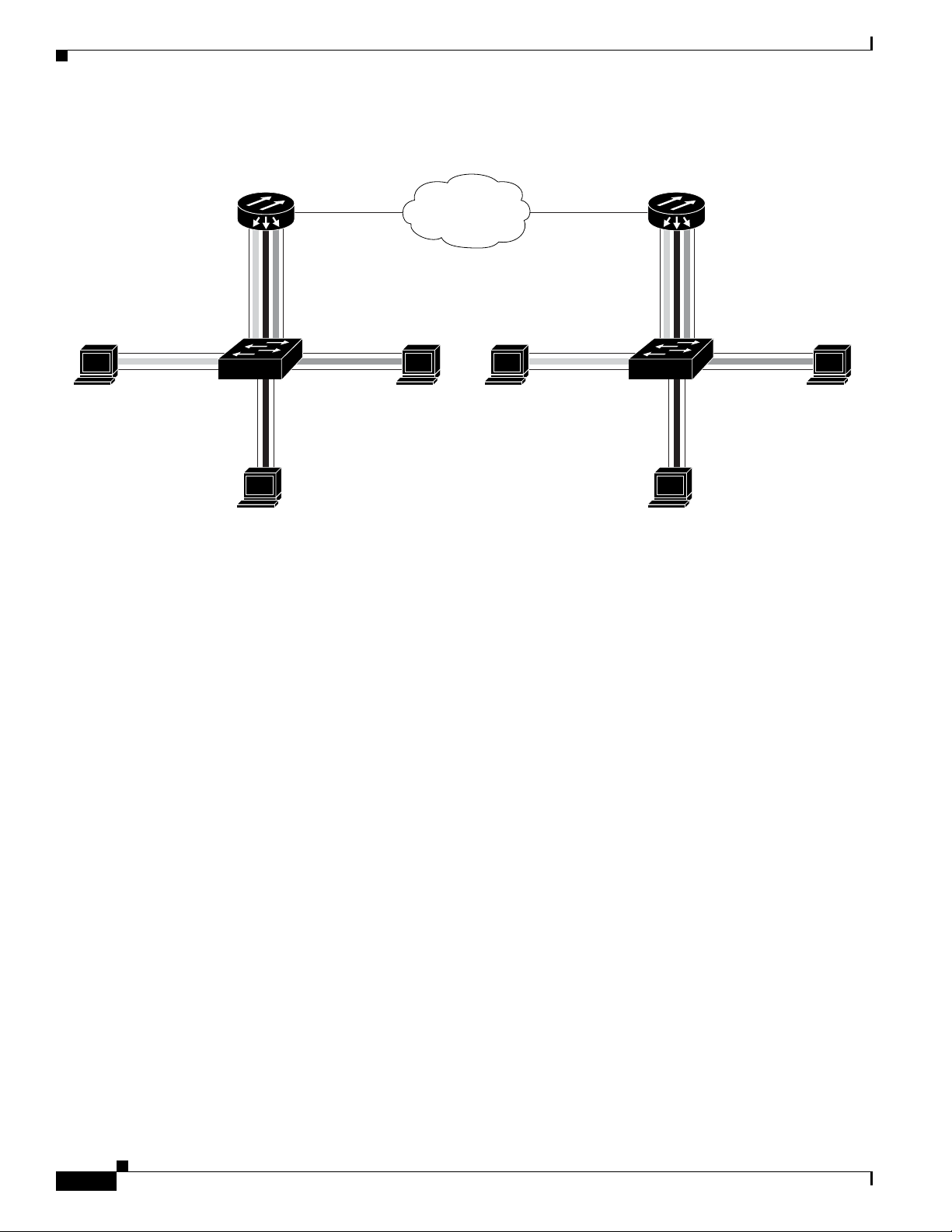
IEEE 802.1Q VLAN Configuration
ML-Series
ML-Series
POS 0POS 0
Router_A
Router_B
124090
SONET/SDH
Fast Ethernet 0.1
Host station
VLAN 2
Host station Host station
VLAN 3
VLAN 4
Fast Ethernet 0.3
Fast Ethernet 0.2
Fast Ethernet 0.4
Switch
802.1.Q
Fast Ethernet 0.1
Host station
VLAN 2
Host station Host station
VLAN 3
VLAN 4
Fast Ethernet 0.3
Fast Ethernet 0.2
Fast Ethernet 0.4
Switch
802.1.Q
Native VLAN 1
Native VLAN 1
Figure 7-2 Bridging IEEE 802.1Q VLANs
Chapter 7 Configuring VLANs on the ML-Series Card
Example 7-1 shows how to configure VLANs for IEEE 802.1Q VLAN encapsulation. Use this
configuration for both ML_Series A and ML_Series B.
Example 7-1 Configure VLANs for IEEE 8021Q VLAN Encapsulation
no ip routing
bridge 1 protocol ieee
bridge 2 protocol ieee
bridge 3 protocol ieee
bridge 4 protocol ieee
!
!
interface FastEthernet0
!
interface FastEthernet0.1
encapsulation dot1Q 1 native
bridge-group 1
!
interface FastEthernet0.2
encapsulation dot1Q 2
bridge-group 2
!
interface FastEthernet0.3
encapsulation dot1Q 3
bridge-group 3
!
interface FastEthernet0.4
encapsulation dot1Q 4
bridge-group 4
!
interface POS0
!
interface POS0.1
encapsulation dot1Q 1 native
bridge-group 1
Cisco ONS 15310-CL and Cisco ONS 15310-MA Ethernet Card Software Feature and Configuration Guide R8.5
7-4
78-18133-01
Page 95

Chapter 7 Configuring VLANs on the ML-Series Card
!
interface POS0.2
encapsulation dot1Q 2
bridge-group 2
!
interface POS0.3
encapsulation dot1Q 3
bridge-group 3
!
interface POS0.4
encapsulation dot1Q 4
bridge-group 4
Monitoring and Verifying VLAN Operation
After the VLANs are configured on the ML-Series card, you can monitor their operation by entering the
privileged EXEC command show vlans [vlan-id] (Example 7-2). This command displays information
on all configured VLANs or on a specific VLAN (by VLAN ID number).
Monitoring and Verifying VLAN Operation
Example 7-2 Output for show vlans Command
ML-Series# show vlans 1
Virtual LAN ID: 1 (IEEE 802.1Q Encapsulation)
vLAN Trunk Interface: POS0.1
This is configured as native Vlan for the following interface(s) :
POS0
Protocols Configured: Address: Received: Transmitted:
Bridging Bridge Group 1 0 0
78-18133-01
Cisco ONS 15310-CL and Cisco ONS 15310-MA Ethernet Card Software Feature and Configuration Guide R8.5
7-5
Page 96

Monitoring and Verifying VLAN Operation
Chapter 7 Configuring VLANs on the ML-Series Card
7-6
Cisco ONS 15310-CL and Cisco ONS 15310-MA Ethernet Card Software Feature and Configuration Guide R8.5
78-18133-01
Page 97

CHA PTER
8
Configuring IEEE 802.1Q Tunneling and Layer 2 Protocol Tunneling on the ML-Series Card
Virtual private networks (VPNs) provide enterprise-scale connectivity on a shared infrastructure, often
Ethernet-based, with the same security, prioritization, reliability, and manageability requirements of
private networks. Tunneling is a feature designed for service providers who carry traffic of multiple
customers across their networks and are required to maintain the VLAN and Layer 2 protocol
configurations of each customer without impacting the traffic of other customers. The ML-Series cards
support IEEE 802.1Q tunneling (QinQ) and Layer 2 protocol tunneling.
This chapter contains the following sections:
• Understanding IEEE 802.1Q Tunneling, page 8-1
• Configuring IEEE 802.1Q Tunneling, page 8-4
• Understanding VLAN-Transparent and VLAN-Specific Services, page 8-6
• VLAN-Transparent and VLAN-Specific Services Configuration Example, page 8-7
• Understanding Layer 2 Protocol Tunneling, page 8-9
• Configuring Layer 2 Protocol Tunneling, page 8-9
Understanding IEEE 802.1Q Tunneling
Business customers of service providers often have specific requirements for VLAN IDs and the number
of VLANs to be supported. The VLAN ranges required by different customers in the same
service-provider network might overlap, and traffic of customers through the infrastructure might be
mixed. Assigning a unique range of VLAN IDs to each customer would restrict customer configurations
and could easily exceed the IEEE 802.1Q specification VLAN limit of 4096.
Using the IEEE 802.1Q tunneling (QinQ) feature, service providers can use a single VLAN to support
customers who have multiple VLANs. Customer VLAN IDs are preserved and traffic from different
customers is segregated within the service-provider infrastructure even when they appear to be on the
same VLAN. The IEEE 802.1Q tunneling expands VLAN space by using a VLAN-in-VLAN hierarchy
and tagging the tagged packets. A port configured to support IEEE 802.1Q tunneling is called a tunnel
port. When you configure tunneling, you assign a tunnel port to a VLAN that is dedicated to tunneling.
Each customer requires a separate VLAN, but that VLAN supports all of the customer’s VLANs.
78-18133-01
Cisco ONS 15310-CL and Cisco ONS 15310-MA Ethernet Card Software Feature and Configuration Guide R8.5
8-1
Page 98

Understanding IEEE 802.1Q Tunneling
Customer A
VLANs 1 to 100
Customer B
VLANs 1 to 200
Customer B
VLANs 1 to 200
Customer A
VLANs 1 to 100
Tunnel port
VLAN 40
Tunnel port
VLAN 40
Trunk
Asymmetric link
Tunnel port
VLAN 30
POS
0
POS
0
Switch_A
SONET STS-N
Switch_B
Fast Ethernet 1
Fast Ethernet 0
Fast Ethernet 1
Fast Ethernet 0
124095
Tunnel port
VLAN 30
ML-Series
ML-Series
Customer traffic tagged in the normal way with appropriate VLAN IDs comes from an IEEE 802.1Q
trunk port on the customer device and into a tunnel port on the ML-Series card. The link between the
customer device and the ML-Series card is an asymmetric link because one end is configured as an
IEEE 802.1Q trunk port and the other end is configured as a tunnel port. You assign the tunnel port
interface to an access VLAN ID unique to each customer (Figure 8-1).
Figure 8-1 IEEE 802.1Q Tunnel Ports in a Service-Provider Network
Chapter 8 Configuring IEEE 802.1Q Tunneling and Layer 2 Protocol Tunneling on the ML-Series Card
8-2
Packets coming from the customer trunk port into the tunnel port on the ML-Series card are normally
IEEE 802.1Q-tagged with an appropriate VLAN ID. The tagged packets remain intact inside the
ML-Series card and, when they exit the trunk port into the service provider network, are encapsulated
with another layer of an IEEE 802.1Q tag (called the metro tag) that contains the VLAN ID unique to
the customer. The original IEEE 802.1Q tag from the customer is preserved in the encapsulated packet.
Therefore, packets entering the service-provider infrastructure are double-tagged, with the outer tag
containing the customer’s access VLAN ID, and the inner VLAN ID being the VLAN of the incoming
traffic.
When the double-tagged packet enters another trunk port in a service provider ML-Series card, the outer
tag is stripped as the packet is processed inside the switch. When the packet exits another trunk port on
the same core switch, the same metro tag is again added to the packet. Figure 8-2 shows the structure of
the double-tagged packet.
Cisco ONS 15310-CL and Cisco ONS 15310-MA Ethernet Card Software Feature and Configuration Guide R8.5
78-18133-01
Page 99

Chapter 8 Configuring IEEE 802.1Q Tunneling and Layer 2 Protocol Tunneling on the ML-Series Card
Double-tagged
frame in service
provider
infrastructure
IEE 802.1Q frame from
customer network
Original Ethernet frame
Destination
address
Length/
EtherType
Frame Check
Sequence
Source
address
SADA Len/Etype Data FCS
SADA Len/Etype DataEtype Tag FCS
SADA Len/Etype DataEtype Ta g Etype Ta g FCS
74072
Figure 8-2 Normal, IEEE 802.1Q, and IEEE 802.1Q-Tunneled Ethernet Packet Formats
Understanding IEEE 802.1Q Tunneling
When the packet enters the trunk port of the service-provider egress switch, the outer tag is again
stripped as the packet is processed internally on the switch. However, the metro tag is not added when it
is sent out the tunnel port on the edge switch into the customer network, and the packet is sent as a normal
IEEE 802.1Q-tagged frame to preserve the original VLAN numbers in the customer network.
In Figure 8-1 on page 8-2, Customer A was assigned VLAN 30, and Customer B was assigned
VLAN 40. Packets entering the ML-Series card tunnel ports with IEEE 802.1Q tags are double-tagged
when they enter the service-provider network, with the outer tag containing VLAN ID 30 or 40,
appropriately, and the inner tag containing the original VLAN number, for example, VLAN 100. Even
if both Customers A and B have VLAN 100 in their networks, the traffic remains segregated within the
service-provider network because the outer tag is different. With IEEE 802.1Q tunneling, each customer
controls its own VLAN numbering space, which is independent of the VLAN numbering space used by
other customers and the VLAN numbering space used by the service-provider network.
At the outbound tunnel port, the original VLAN numbers on the customer’s network are recovered. If
the traffic coming from a customer network is not tagged (native VLAN frames), these packets are
bridged or routed as if they were normal packets, and the metro tag is added (as a single-level tag) when
they exit toward the service provider network.
If the native VLAN (VLAN 1) is used in the service provider network as a metro tag, this tag must always
be added to the customer traffic, even though the native VLAN ID is not normally added to transmitted
frames. If the VLAN 1 metro tag is not added on frames entering the service provider network, then the
customer VLAN tag appears to be the metro tag, with disastrous results. The global configuration vlan
dot1q tag native command must be used to prevent this by forcing a tag to be added to VLAN 1.
Avoiding the use of VLAN 1 as a metro tag transporting customer traffic is recommended to reduce the
risk of misconfiguration. A best practice is to use VLAN 1 as a private management VLAN in the service
provider network.
The IEEE 802.1Q class of service (COS) priority field on the added metro tag is set to zero by default,
78-18133-01
but can be modified by input or output policy maps.
Cisco ONS 15310-CL and Cisco ONS 15310-MA Ethernet Card Software Feature and Configuration Guide R8.5
8-3
Page 100

Chapter 8 Configuring IEEE 802.1Q Tunneling and Layer 2 Protocol Tunneling on the ML-Series Card
Configuring IEEE 802.1Q Tunneling
Configuring IEEE 802.1Q Tunneling
This section includes the following information about configuring IEEE 802.1Q tunneling:
• IEEE 802.1Q Tunneling and Compatibility with Other Features, page 8-4
• Configuring an IEEE 802.1Q Tunneling Port, page 8-4
• IEEE 802.1Q Example, page 8-5
Note By default, IEEE 802.1Q tunneling is not configured on the ML-Series.
IEEE 802.1Q Tunneling and Compatibility with Other Features
Although IEEE 802.1Q tunneling works well for Layer 2 packet switching, there are incompatibilities
with some Layer 2 features and with Layer 3 switching:
• A tunnel port cannot be a routed port.
• Tunnel ports do not support IP access control lists (ACLs).
• Layer 3 quality of service (QoS) ACLs and other QoS features related to Layer 3 information are
not supported on tunnel ports. MAC-based QoS is supported on tunnel ports.
• EtherChannel port groups are compatible with tunnel ports as long as the IEEE 802.1Q
configuration is consistent within an EtherChannel port group.
• Port Aggregation Protocol (PAgP) and Unidirectional Link Detection (UDLD) Protocol are not
supported on IEEE 802.1Q tunnel ports.
• Dynamic Trunking Protocol (DTP) is not compatible with IEEE 802.1Q tunneling because you must
manually configure asymmetric links with tunnel ports and trunk ports.
• Loopback detection is supported on IEEE 802.1Q tunnel ports.
• When a port is configured as an IEEE 802.1Q tunnel port, spanning tree bridge protocol data unit
(BPDU) filtering is automatically disabled on the interface.
Configuring an IEEE 802.1Q Tunneling Port
Beginning in privileged EXEC mode, follow these steps to configure a port as an IEEE 802.1Q tunnel
port:
Command Purpose
Step 1
Step 2
Step 3
ML_Series# configure terminal
ML_Series(config)# bridge
bridge-number
ML_Series(config)# interface
fastethernet
protocol
number
bridge-protocol
Enters global configuration mode.
Creates a bridge number and specifies a protocol.
Enters the interface configuration mode and the interface to be
configured as a tunnel port. This should be the edge port in the
service-provider network that connects to the customer switch. Valid
interfaces include physical interfaces and port-channel logical
interfaces.
8-4
Cisco ONS 15310-CL and Cisco ONS 15310-MA Ethernet Card Software Feature and Configuration Guide R8.5
78-18133-01
 Loading...