

Page 1

Installing the High-Density Electrical Interface
Assemblies on the Cisco ONS 15310-MA
Product Name: 15310-EIA-HD-A, 15310-EIA-HD-B
This document explains how to install and remove high-density electrical interface assemblies (EIAs)
on the Cisco ONS 15310-MA.As appropriate, use this document in conjunction with the
Cisco ONS 15310-CL and Cisco ONS 15310-MA Procedure Guide, the Cisco ONS 15310-CL and
Cisco ONS 15310-MA Reference Manual, and the Cisco ONS 15310-CL and Cisco ONS 15310-MA
Troubleshooting Guide when working with the high-density EIAs.
This document contains the following sections:
• High-Density EIA Description, page 1
• Install the High-Density EIAs, page 3
• Related Documentation, page 5
• Obtaining Documentation and Submitting a Service Request, page 5
High-Density EIA Description
High-density EIAs are attached to the ONS 15310-MA shelf assembly backplane to provide up to 168
transmit and receive DS-1 connections through six Champ connectors per side (A and B) or six transmit
and receive DS-3/EC-1 connections through six BNC connectors per side. The EIAs are designed to
support DS-1, DS-3, and EC-1 signals. The appropriate cable assembly is required depending on the type
of signal.
Note The HD expansion connectors on the high-density EIA are not supported in Software Release 7.0.x and
earlier.
You can install EIAs on one or both sides of the ONS 15310-MA. As you face the rear of the shelf
assembly, the right side is the A side (15310-EIA-HD-A) and the left side is the B side
(15310-EIA-HD-B).
Americas Headquarters:
Cisco Systems, Inc., 170 West Tasman Drive, San Jose, CA 95134-1706 USA
Page 2

High-Density EIA Description
Figure 1 shows the J connectors on the A- and B-side high-density EIAs installed on the ONS
15310-MA.
Figure 1 High-Density EIA Connectors
PWR B J1-LAN
P/N
COO
J5-BITS2 J7-ALM OUT
PWR AJ6-ALM INPUT
J2-CRFT J3-UDC J4-BITS1RTN -48VDC
P/N
DS1
OUT
J21
PID VIDS/NCLEI CODEBAR CODE
PID VID S/N BAR CODE CLEI CODE
DS1
OUT
J8
COO
-48VDC RTN
J33-HD DS3
DS1
IN
J22
DS1
OUT
J23
DS1
IN
J24
DS1
OUT
J25
DS1
IN
J26
J31-OUTJ30-INJ29-OUT
312
J32-INJ28-INJ27-OUT
DS1
IN
J9
DS1
OUT
J10
DS1
IN
J11
DS1
OUT
J12
DS1
IN
J13
J15-IN J16-OUT J17-IN
132
J14-OUT J18-OUT J19-IN
J20-HD DS3
Figure 2 shows the A- and B-side high-density EIAs installed on the ONS 15310-MA.
151584
Installing the High-Density Electrical Interface Assemblies on the Cisco ONS 15310-MA
2
78-17418-01
Page 3

Figure 2 High-Density EIA Installation
High-Density EIA Installation
High-Density EIA Installation
To install the EIA on the rear of the shelf assembly, you must first remove the standard sheet metal
covers. The EIAs use the same screw holes as the standard sheet metal covers, but they use three holes
for panhead screws and two holes for jack screws.
When installed with the standard door and cabling on the backplane, the ONS 15310-MA shelf measures
approximately 13.7 inches deep when fully populated with backplane cables.
Install the High-Density EIAs
The following parts are needed to install the high-density EIAs.
• #2 Phillips screwdriver
• High-density EIA(s)
• 6-32 x 5/16-inch pan head screws (3, included with EIA)
EIA installed
on the B Side
EIA installed
on the A Side
151575
Caution Always use the supplied ESD wristband when working with a powered ONS 15310-MA. Plug the
wristband cable into either of the ESD jacks, on the far left and right faceplates in the shelf.
78-17418-01
Installing the High-Density Electrical Interface Assemblies on the Cisco ONS 15310-MA
3
Page 4

Install the High-Density EIAs
151576
Step 1 Remove the blank sheet metal covers. Use a Phillips screwdriver to remove the five screws holding each
sheet metal cover in place.
Figure 3 shows the screw locations of the sheet metal covers installed on the A- and B-side of the ONS
15310-MA.
Figure 3 Blank Sheet Metal Covers
Step 2
Determine which high-density EIA is designed for installation on the B Side and which is designed for
installation on the A Side (Figure 2 on page 3).
Step 3 Align the connectors on the EIA you want to install with the mating connectors on the backplane, using the
plastic guide posts on the connectors.
Caution Do not firmly apply pressure to the EIA; this could damage the EIA and backplane connectors.
Step 4 Seat the EIA as flat as possible by gently exerting enough pressure with your hands to only partially seat the
connectors. Do not try and fully insert the EIA.
Step 5 Locate the two jack screws on the EIA, which are found on the opposite corners (Figure 2 on page 3). (For
example, on the B-side EIA, the screws are located in the top right and bottom left corners.)
Step 6 Starting with either jack screw, tighten the thumb screw turn five full turns, then turn the other thumb
screw five full turns (Figure 4). Alternate between the jack screws until the EIA is full seated onto the
chassis and the jack screws are hand tight. The EIA is fully mated when both jack screws are fully threaded
into the chassis.
Installing the High-Density Electrical Interface Assemblies on the Cisco ONS 15310-MA
4
Blank sheet metal cover
installed on the B Side
Blank sheet metal cover
installed on the A Side
78-17418-01
Page 5
Related Documentation
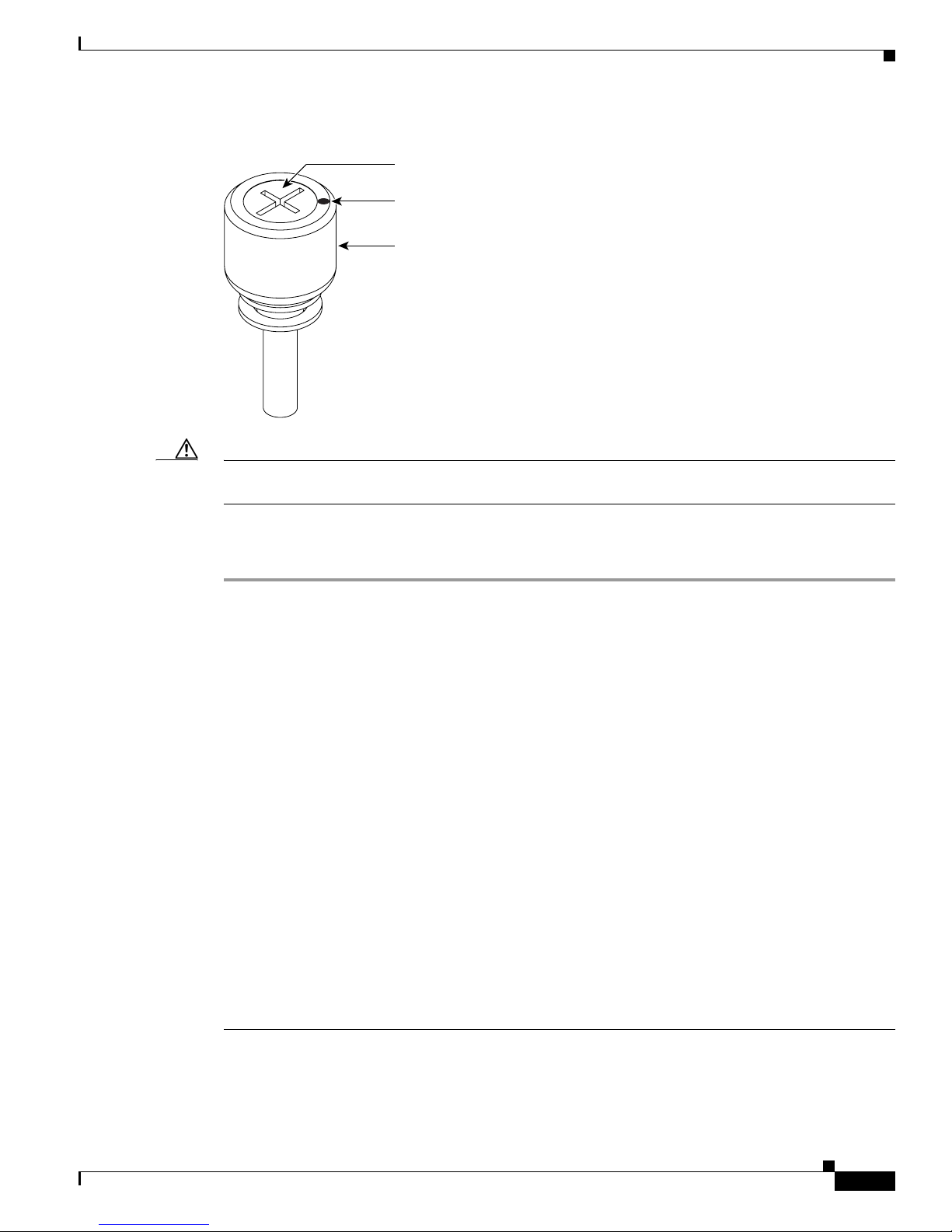
Figure 4 EIA Jack Screw
Inner screw
Rotation indicator
Thumbscrew
115260
Caution Threading one jack screw completely before threading the other jack screw might result in connector
misalignment and damage to the EIA. Do not overtighten the jack screws.
Step 7 Install the remaining three 6-32 x 5/16-inch pan head screws onto the EIA and torque to 8 to 10 in-lbs.
Step 8 Repeat Steps 3 through 7 to install the other EIA, as necessary.
Related Documentation
• Cisco ONS 15310-CL and Cisco ONS 15310-MA Procedure Guide
• Cisco ONS 15310-CL and Cisco ONS 15310-MA Reference Manual
• Cisco ONS 15310-CL and Cisco ONS 15310-MA Troubleshooting Guide
Obtaining Documentation and Submitting a Service Request
For information on obtaining documentation, submitting a service request, and gathering additional
information, see the monthly What’s New in Cisco Product Documentation, which also lists all new and
revised Cisco technical documentation, at:
http://www.cisco.com/en/US/docs/general/whatsnew/whatsnew.html
Subscribe to the What’s New in Cisco Product Documentation as an RSS feed and set content to be
delivered directly to your desktop using a reader application. The RSS feeds are a free service. Cisco currently
supports RSS Version 2.0.
This document is to be used in conjunction with the documents listed in the “Related Documentation” section.
Cisco and the Cisco Logo are trademarks of Cisco Systems, Inc. and/or its affiliates in the U.S. and other countries. A listing of Cisco's trademarks
can be found at www.cisco.com/go/trademarks. Third party trademarks mentioned are the property of their respective owners. The use of the word
partner does not imply a partnership relationship between Cisco and any other company. (1005R)
78-17418-01
Installing the High-Density Electrical Interface Assemblies on the Cisco ONS 15310-MA
5
Page 6
Related Documentation
Any Internet Protocol (IP) addresses and phone numbers used in this document are not intended to be actual addresses and phone numbers. Any
examples, command display output, network topology diagrams, and other figures included in the document are shown for illustrative purposes only.
Any use of actual IP addresses or phone numbers in illustrative content is unintentional and coincidental.
© 2011 Cisco Systems, Inc. All rights reserved.
Printed in the USA on recycled paper containing 10% postconsumer waste.
Installing the High-Density Electrical Interface Assemblies on the Cisco ONS 15310-MA
6
78-17418-01
 Loading...