

Page 1

Configuring the Management Interface
Information About the Management Interface, page 295
•
Configuring the Management Interface (GUI), page 296
•
Configuring the Management Interface (CLI), page 297
•
Information About the Management Interface
The management interface is the default interface for in-band management of the controller and connectivity
to enterprise services such as AAA servers. It is also used for communications between the controller and
access points. The management interface has the only consistently “pingable” in-band interface IP address on
the controller. You can access the GUI of the controller by entering the management interface IP address of
the controller in the address field of either Internet Explorer or Mozilla Firefox browser.
For CAPWAP, the controller requires one management interface to control all inter-controller communications
and one AP-manager interface to control all controller-to-access point communications, regardless of the
number of ports.
CHAPTER 27
Note
Caution
Caution
OL-28744-01 295
To prevent or block a wired or wireless client from accessing the management network on a controller
(from the wireless client dynamic interface or VLAN), the network administrator must ensure that only
authorized clients gain access to the management network through proper CPU ACLs, or use a firewall
between the client dynamic interface and the management network.
Do not map a guest WLAN to the management interface. If the EoIP tunnel breaks, the client could obtain
an IP and be placed on the management subnet.
Do not configure wired clients in the same VLAN or subnet of the service port of the controller on the
network. If you configure wired clients on the same subnet or VLAN as the service port, it is not possible
to access the management interface of the controller.
Cisco Wireless LAN Controller Configuration Guide, Release 7.4
Page 2

Configuring the Management Interface (GUI)
Configuring the Management Interface (GUI)
Step 1
Step 2
Step 3
Choose Controller > Interfaces to open the Interfaces page.
Click the management link.
The Interfaces > Edit page appears.
Set the management interface parameters:
Note
The management interface uses the controller’s factory-set distribution system MAC address.
Quarantine and quarantine VLAN ID, if applicable
•
Note
Select the Quarantine check box if you want to configure this VLAN as unhealthy or you want to configure
network access control (NAC) out-of-band integration. Doing so causes the data traffic of any client that
is assigned to this VLAN to pass through the controller.
NAT address (only Cisco 2500 Series Controllers and Cisco 5500 Series Controllers are configured for dynamic
•
AP management.)
Note
Select the Enable NAT Address check box and enter the external NAT IP address if you want to be able
to deploy your Cisco 2500 Series Controllers or Cisco 5500 Series Controller behind a router or other
gateway device that is using one-to-one mapping network address translation (NAT). NAT allows a device,
such as a router, to act as an agent between the Internet (public) and a local network (private). In this case,
it maps the controller’s intranet IP addresses to a corresponding external address. The controller’s dynamic
AP-manager interface must be configured with the external NAT IP address so that the controller can send
the correct IP address in the Discovery Response.
Note
If a Cisco 2500 Series Controllers or Cisco 5500 Series Controller is configured with an external NAT IP
address under the management interface, the APs in local mode cannot associate with the controller. The
workaround is to either ensure that the management interface has a globally valid IP address or ensure
that external NAT IP address is valid internally for the local APs.
Note
The NAT parameters are supported for use only with one-to-one-mapping NAT, where each private client
has a direct and fixed mapping to a global address. The NAT parameters do not support one-to-many NAT,
which uses source port mapping to enable a group of clients to be represented by a single IP address.
VLAN identifier
•
Note
Enter 0 for an untagged VLAN or a nonzero value for a tagged VLAN. We recommend using tagged
VLANs for the management interface.
Fixed IP address, IP netmask, and default gateway
•
Dynamic AP management (for Cisco 2500 Series Controllers or Cisco 5500 Series Controller only)
•
Note
For Cisco 5500 Series Controllers, the management interface acts like an AP-manager interface by default.
If desired, you can disable the management interface as an AP-manager interface and create another
dynamic interface as an AP manager.
Physical port assignment (for all controllers except the Cisco 2500 Series Controllers or Cisco 5500 Series Controller)
•
Primary and secondary DHCP servers
•
Access control list (ACL) setting, if required
•
Cisco Wireless LAN Controller Configuration Guide, Release 7.4
296 OL-28744-01
Page 3

Configuring the Management Interface (CLI)
Step 4
Step 5
Click Save Configuration.
If you made any changes to the management or virtual interface, reboot the controller so that your changes take effect.
Configuring the Management Interface (CLI)
Step 1
Step 2
Step 3
Enter the show interface detailed management command to view the current management interface settings.
Note
The management interface uses the controller’s factory-set distribution system MAC address.
Enter the config wlan disable wlan-number command to disable each WLAN that uses the management interface for
distribution system communication.
Enter these commands to define the management interface:
config interface address management ip-addr ip-netmask gateway
•
config interface quarantine vlan management vlan_id
•
Note
Use the config interface quarantine vlan management vlan_id command to configure a quarantine
VLAN on the management interface.
config interface vlan management {vlan-id | 0}
•
Note
Enter 0 for an untagged VLAN or a nonzero value for a tagged VLAN. We recommend using tagged
VLANs for the management interface.
Step 4
config interface ap-manager management {enable | disable} (for Cisco 5500 Series Controllers only)
•
Note
Use the config interface ap-manager management {enable | disable} command to enable or disable
dynamic AP management for the management interface. For Cisco 5500 Series Controllers, the management
interface acts like an AP-manager interface by default. If desired, you can disable the management interface
as an AP-manager interface and create another dynamic interface as an AP manager.
config interface port management physical-ds-port-number (for all controllers except the 5500 series)
•
config interface dhcp management ip-address-of-primary-dhcp-server [ip-address-of-secondary-dhcp-server]
•
config interface acl management access-control-list-name
•
Enter these commands if you want to be able to deploy your Cisco 5500 Series Controller behind a router or other gateway
device that is using one-to-one mapping network address translation (NAT):
config interface nat-address management {enable | disable}
•
config interface nat-address management set public_IP_address
•
NAT allows a device, such as a router, to act as an agent between the Internet (public) and a local network (private). In
this case, it maps the controller’s intranet IP addresses to a corresponding external address. The controller’s dynamic
AP-manager interface must be configured with the external NAT IP address so that the controller can send the correct
IP address in the Discovery Response.
Cisco Wireless LAN Controller Configuration Guide, Release 7.4
OL-28744-01 297
Page 4

Configuring the Management Interface (CLI)
Step 5
Step 6
Step 7
Note
These commands are supported for use only with one-to-one-mapping NAT, where each private client has a
direct and fixed mapping to a global address. These commands do not support one-to-many NAT, which uses
source port mapping to enable a group of clients to be represented by a single IP address.
Enter the save config command.
Enter the show interface detailed management command to verify that your changes have been saved.
If you made any changes to the management interface, enter the reset system command to reboot the controller in order
for the changes to take effect.
Cisco Wireless LAN Controller Configuration Guide, Release 7.4
298 OL-28744-01
Page 5

Configuring the AP-Manager Interface
Information the About AP-Manager Interface, page 299
•
Restrictions for Configuring AP Manager Interfaces, page 299
•
Configuring the AP-Manager Interface (GUI), page 300
•
Configuring the AP Manager Interface (CLI), page 300
•
Configuration Example: Configuring AP-Manager on a Cisco 5500 Series Controller, page 301
•
Information the About AP-Manager Interface
A controller has one or more AP-manager interfaces, which are used for all Layer 3 communications between
the controller and lightweight access points after the access points have joined the controller. The AP-manager
IP address is used as the tunnel source for CAPWAP packets from the controller to the access point and as
the destination for CAPWAP packets from the access point to the controller.
CHAPTER 28
Note
The controller does not support transmitting the jumbo frames. To avoid having the controller transmit
CAPWAP packets to the AP that will necessitate fragmentation and reassembly, reduce MTU/MSS on
the client side.
The AP-manager interface communicates through any distribution system port by listening across the Layer
3 network for access point CAPWAP or LWAPP join messages to associate and communicate with as many
lightweight access points as possible.
Restrictions for Configuring AP Manager Interfaces
The MAC address of the management interface and the AP-manager interface is the same as the base
•
LAG MAC address.
If only one distribution system port can be used, you should use distribution system port 1.
•
•
Cisco Wireless LAN Controller Configuration Guide, Release 7.4
OL-28744-01 299
Page 6

Configuring the AP-Manager Interface (GUI)
An AP-manager interface is not required to be configured. The management interface acts like an
•
AP-manager interface by default, and the access points can join on this interface.
If link aggregation (LAG) is enabled, there can be only one AP-manager interface. But when LAG is
•
disabled, one or more AP-manager interfaces can be created, generally one per physical port.
Port redundancy for the AP-manager interface is not supported. You cannot map the AP-manager
•
interface to a backup port.
Configuring the AP-Manager Interface (GUI)
Step 1
Step 2
Step 3
Step 4
Step 5
Choose Controller > Interfaces to open the Interfaces page.
Click AP-Manager Interface.
The Interface > Edit page appears.
Set the AP-Manager Interface parameters:
Note
Click Save Configuration to save your changes.
If you made any changes to the management or virtual interface, reboot the controller so that your changes take effect.
For Cisco 5500 Series Controllers, you are not required to configure an AP-manager interface. The management
interface acts like an AP-manager interface by default.
Physical port assignment
•
VLAN identifier
•
Note
Fixed IP address, IP netmask, and default gateway
•
Primary and secondary DHCP servers
•
Access control list (ACL) name, if required
•
Enter 0 for an untagged VLAN or a nonzero value for a tagged VLAN. We recommend using tagged
VLANs for the AP-manager interface.
Configuring the AP Manager Interface (CLI)
Before You Begin
For Cisco 5500 Series Controllers, you are not required to configure an AP-manager interface. The management
interface acts like an AP-manager interface by default.
Step 1
300 OL-28744-01
Enter the show interface summary command to view the current interfaces.
Note
Cisco Wireless LAN Controller Configuration Guide, Release 7.4
If the system is operating in Layer 2 mode, the AP-manager interface is not
listed.
Page 7

Configuration Example: Configuring AP-Manager on a Cisco 5500 Series Controller
Step 2
Step 3
Step 4
Step 5
Step 6
Enter the show interface detailed ap-manager command to view the current AP-manager interface settings.
Enter the config wlan disable wlan-number command to disable each WLAN that uses the AP-manager interface for
distribution system communication.
Enter these commands to define the AP-manager interface:
config interface address ap-manager ip-addr ip-netmask gateway
•
config interface vlan ap-manager {vlan-id | 0}
•
Note
config interface port ap-manager physical-ds-port-number
•
config interface dhcp ap-manager ip-address-of-primary-dhcp-server [ip-address-of-secondary-dhcp-server]
•
config interface acl ap-manager access-control-list-name
•
Enter the save config command to save your changes.
Enter the show interface detailed ap-manager command to verify that your changes have been saved.
Enter 0 for an untagged VLAN or a nonzero value for a tagged VLAN. We recommend using tagged
VLANs for the AP-manager interface.
Configuration Example: Configuring AP-Manager on a Cisco 5500 Series
Controller
For a Cisco 5500 Series Controller, we recommend that you have eight dynamic AP-manager interfaces and
associate them to the eight Gigabit ports of the controller when LAG is not used. If you are using the
management interface, which acts like an AP-manager interface by default, you must create only seven more
dynamic AP-manager interfaces and associate them to the remaining seven Gigabit ports.
Cisco Wireless LAN Controller Configuration Guide, Release 7.4
OL-28744-01 301
Page 8
Configuration Example: Configuring AP-Manager on a Cisco 5500 Series Controller
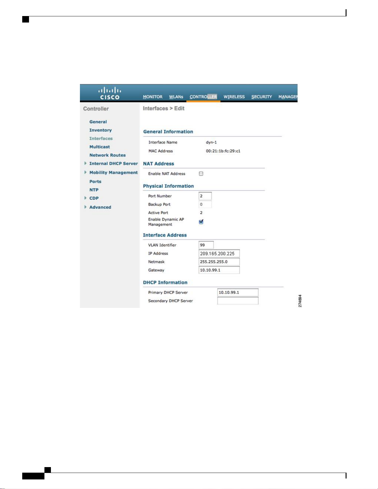
This figure shows a dynamic interface that is enabled as a dynamic AP-manager interface and associated to
port number 2.
Figure 35: Dynamic Interface Example with Dynamic AP Management
Cisco Wireless LAN Controller Configuration Guide, Release 7.4
302 OL-28744-01
Page 9

Configuration Example: Configuring AP-Manager on a Cisco 5500 Series Controller
This figure shows a Cisco 5500 Series Controller with LAG disabled, the management interface used as one
dynamic AP-manager interface, and seven additional dynamic AP-manager interfaces, each mapped to a
different Gigabit port.
Figure 36: Cisco 5500 Series Controller Interface Configuration Example
Cisco Wireless LAN Controller Configuration Guide, Release 7.4
OL-28744-01 303
Page 10

Configuration Example: Configuring AP-Manager on a Cisco 5500 Series Controller
Cisco Wireless LAN Controller Configuration Guide, Release 7.4
304 OL-28744-01
Page 11

Configuring Virtual Interfaces
Information About the Virtual Interface, page 305
•
Configuring Virtual Interfaces (GUI), page 306
•
Configuring Virtual Interfaces (CLI), page 306
•
Information About the Virtual Interface
The virtual interface is used to support mobility management, Dynamic Host Configuration Protocol (DHCP)
relay, and embedded Layer 3 security such as guest web authentication and VPN termination. It also maintains
the DNS gateway host name used by Layer 3 security and mobility managers to verify the source of certificates
when Layer 3 web authorization is enabled.
Specifically, the virtual interface plays these two primary roles:
Acts as the DHCP server placeholder for wireless clients that obtain their IP address from a DHCP
•
server.
CHAPTER 29
Serves as the redirect address for the web authentication login page.
•
The virtual interface IP address is used only in communications between the controller and wireless clients.
It never appears as the source or destination address of a packet that goes out a distribution system port and
onto the switched network. For the system to operate correctly, the virtual interface IP address must be set (it
cannot be 0.0.0.0), and no other device on the network can have the same address as the virtual interface.
Therefore, the virtual interface must be configured with an unassigned and unused gateway IP address. The
virtual interface IP address is not pingable and should not exist in any routing table in your network. In addition,
the virtual interface cannot be mapped to a physical port.
Note
OL-28744-01 305
All controllers within a mobility group must be configured with the same virtual interface IP address.
Otherwise, inter-controller roaming may appear to work, but the handoff does not complete, and the client
loses connectivity for a period of time.
Cisco Wireless LAN Controller Configuration Guide, Release 7.4
Page 12

Configuring Virtual Interfaces (GUI)
Configuring Virtual Interfaces (GUI)
Step 1
Step 2
Step 3
Step 4
Step 5
Choose Controller > Interfaces to open the Interfaces page.
Click Virtual.
The Interfaces > Edit page appears.
Enter the following parameters:
Any fictitious, unassigned, and unused gateway IP address
•
DNS gateway hostname
•
Note
Click Save Configuration.
If you made any changes to the management or virtual interface, reboot the controller so that your changes take effect.
To ensure connectivity and web authentication, the DNS server should always point to the virtual interface.
If a DNS hostname is configured for the virtual interface, then the same DNS host name must be configured
on the DNS server(s) used by the client.
Configuring Virtual Interfaces (CLI)
Step 1
Step 2
Step 3
Enter the show interface detailed virtual command to view the current virtual interface settings.
Enter the config wlan disable wlan-number command to disable each WLAN that uses the virtual interface for distribution
system communication.
Enter these commands to define the virtual interface:
config interface address virtual ip-address
•
Note
config interface hostname virtual dns-host-name
•
Step 4
Step 5
306 OL-28744-01
Enter the reset system command. At the confirmation prompt, enter Y to save your configuration changes to NVRAM.
The controller reboots.
Enter the show interface detailed virtual command to verify that your changes have been saved.
Cisco Wireless LAN Controller Configuration Guide, Release 7.4
For ip-address, enter any fictitious, unassigned, and unused gateway IP address.
Page 13

Configuring Service-Port Interfaces
Information About Service-Port Interfaces, page 307
•
Restrictions for Configuring Service-Port Interfaces, page 307
•
Configuring Service-Port Interfaces (GUI), page 307
•
Configuring Service-Port Interfaces (CLI), page 308
•
Information About Service-Port Interfaces
The service-port interface controls communications through and is statically mapped by the system to the
service port. The service port can obtain an IP address using DHCP, or it can be assigned a static IP address,
but a default gateway cannot be assigned to the service-port interface. Static routes can be defined through
the controller for remote network access to the service port.
CHAPTER 30
Restrictions for Configuring Service-Port Interfaces
Only Cisco 7500 Series Controllers and Cisco 5500 Series Controllers have a physical service-port
•
interface that is reachable from the external network.
Configuring Service-Port Interfaces (GUI)
Step 1
Step 2
Step 3
Choose Controller > Interfaces to open the Interfaces page.
Click the service-port link to open the Interfaces > Edit page.
Enter the Service-Port Interface parameters:
Note
The service-port interface uses the controller’s factory-set service-port MAC address.
DHCP protocol (enabled)
•
DHCP protocol (disabled) and IP address and IP netmask
•
Cisco Wireless LAN Controller Configuration Guide, Release 7.4
OL-28744-01 307
Page 14

Configuring Service-Port Interfaces (CLI)
Step 4
Step 5
Click Save Configuration to save your changes.
If you made any changes to the management or virtual interface, reboot the controller so that your changes take effect.
Configuring Service-Port Interfaces (CLI)
Step 1
Step 2
To view the current service-port interface settings, enter this command:
show interface detailed service-port
Note
Enter these commands to define the service-port interface:
The service-port interface uses the controller’s factory-set service-port MAC address.
To configure the DHCP server, enter this command:
•
config interface dhcp service-port enable
To disable the DHCP server, enter this command:
•
config interface dhcp service-port disable
To configure the IP address, enter this command:
•
config interface address service-port ip-addr ip-netmask
Step 3
Step 4
Step 5
The service port is used for out-of-band management of the controller. If the management workstation is in a remote
subnet, you may need to add a route on the controller in order to manage the controller from that remote workstation.
To do so, enter this command:
config route add network-ip-addr ip-netmask gateway
Enter the save config command to save your changes.
Enter the show interface detailed service-port command to verify that your changes have been saved.
Cisco Wireless LAN Controller Configuration Guide, Release 7.4
308 OL-28744-01
Page 15

Configuring Dynamic Interfaces
Information About Dynamic Interface, page 309
•
Pre - requisites for Configuring Dynamic Interfaces, page 310
•
Restrictions for Configuring Dynamic Interfaces, page 310
•
Configuring Dynamic Interfaces (GUI), page 310
•
Configuring Dynamic Interfaces (CLI), page 312
•
Information About Dynamic Interface
Dynamic interfaces, also known as VLAN interfaces, are created by users and designed to be analogous to
VLANs for wireless LAN clients. A controller can support up to 512 dynamic interfaces (VLANs). Each
dynamic interface is individually configured and allows separate communication streams to exist on any or
all of a controller’s distribution system ports. Each dynamic interface controls VLANs and other communications
between controllers and all other network devices, and each acts as a DHCP relay for wireless clients associated
to WLANs mapped to the interface. You can assign dynamic interfaces to distribution system ports, WLANs,
the Layer 2 management interface, and the Layer 3 AP-manager interface, and you can map the dynamic
interface to a backup port.
You can configure zero, one, or multiple dynamic interfaces on a distribution system port. However, all
dynamic interfaces must be on a different VLAN or IP subnet from all other interfaces configured on the port.
If the port is untagged, all dynamic interfaces must be on a different IP subnet from any other interface
configured on the port.
This table lists the maximum number of VLANs supported on the various controller platforms.
CHAPTER 31
Table 7: Maximum number of VLANs supported on Cisco Wireless Controllers
Maximum VLANsWireless Controllers
512Cisco Virtual Wireless Controller
16Cisco Wireless Controller Module for ISR G2
16Cisco 2500 Series Wireless Controllers
Cisco Wireless LAN Controller Configuration Guide, Release 7.4
OL-28744-01 309
Page 16

Pre - requisites for Configuring Dynamic Interfaces
Maximum VLANsWireless Controllers
512Cisco 5500 Series Wireless Controller
512Cisco Catalyst 6500 Series Wireless Services
Module2 (WiSM2)
4,096Cisco Flex 7500 Series Cloud Controller
4,096Cisco 8500 Series Controller
Pre - requisites for Configuring Dynamic Interfaces
While configuring on the dynamic interface of the controller, you must ensure the following:
•
You must use tagged VLANs for dynamic interfaces.
•
Restrictions for Configuring Dynamic Interfaces
The following restrictions apply for configuring the dynamic interfaces on the controller:
You must not configure a dynamic interface in the same subnetwork as a server that is reachable by the
•
controller CPU, such as a RADIUS server, as it might cause asymmetric routing issues.
Wired clients cannot access management interface of the Cisco WLC 2500 series using the IP address
•
of the AP Manager interface – when Dynamic AP Management is enabled on a dynamic VLAN.
•
For SNMP requests that come from a subnet that is configured as a dynamic interface, the controller
•
responds but the response does not reach the device that initiated the conversation.
If you are using DHCP proxy and/or a RADIUS source interface, ensure that the dynamic interface has
•
a valid routable address. Duplicate or overlapping addresses across controller interfaces are not supported.
Configuring Dynamic Interfaces (GUI)
Step 1
Step 2
Choose Controller > Interfaces to open the Interfaces page.
Perform one of the following:
To create a new dynamic interface, click New. The Interfaces > New page appears. Go to Step 3.
•
To modify the settings of an existing dynamic interface, click the name of the interface. The Interfaces > Edit
•
page for that interface appears. Go to Step 5.
Cisco Wireless LAN Controller Configuration Guide, Release 7.4
310 OL-28744-01
Page 17

Configuring Dynamic Interfaces (GUI)
To delete an existing dynamic interface, hover your cursor over the blue drop-down arrow for the desired interface
•
and choose Remove.
Step 3
Step 4
Step 5
Enter an interface name and a VLAN identifier, as shown in the figure above.
Click Apply to commit your changes. The Interfaces > Edit page appears.
Configure the following parameters:
Guest LAN, if applicable
•
Quarantine and quarantine VLAN ID, if applicable
•
Note
Select the Quarantine check box if you want to configure this VLAN as unhealthy or you want to configure
network access control (NAC) out-of-band integration. Doing so causes the data traffic of any client that
is assigned to this VLAN to pass through the controller.
Physical port assignment (for all controllers except the 5500 series)
•
NAT address (only for Cisco 5500 Series Controllers configured for dynamic AP management)
•
Note
Select the Enable NAT Address check box and enter the external NAT IP address if you want to be able
to deploy your Cisco 5500 Series Controller behind a router or other gateway device that is using one-to-one
mapping network address translation (NAT). NAT allows a device, such as a router, to act as an agent
between the Internet (public) and a local network (private). In this case, it maps the controller’s intranet
IP addresses to a corresponding external address. The controller’s dynamic AP-manager interface must
be configured with the external NAT IP address so that the controller can send the correct IP address in
the Discovery Response.
Note
The NAT parameters are supported for use only with one-to-one-mapping NAT, where each private client
has a direct and fixed mapping to a global address. The NAT parameters do not support one-to-many NAT,
which uses source port mapping to enable a group of clients to be represented by a single IP address.
Dynamic AP management
•
Note
When you enable this feature, this dynamic interface is configured as an AP-manager interface (only one
AP-manager interface is allowed per physical port). A dynamic interface that is marked as an AP-manager
interface cannot be used as a WLAN interface.
Note
Set the APs in a VLAN that is different than the dynamic interface configured on the controller. If the APs
are in the same VLAN as the dynamic interface, the APs are not registered on the controller and the
“LWAPP discovery rejected” and “Layer 3 discovery request not received on management VLAN” errors
are logged on the controller.
VLAN identifier
•
Fixed IP address, IP netmask, and default gateway
•
Primary and secondary DHCP servers
•
Access control list (ACL) name, if required
•
To ensure proper operation, you must set the Port Number and Primary DHCP Server parameters.Note
Step 6
Step 7
OL-28744-01 311
Click Save Configuration to save your changes.
Repeat this procedure for each dynamic interface that you want to create or edit.
Cisco Wireless LAN Controller Configuration Guide, Release 7.4
Page 18

Configuring Dynamic Interfaces (CLI)
Configuring Dynamic Interfaces (CLI)
Step 1
Step 2
Step 3
Step 4
Enter the show interface summary command to view the current dynamic interfaces.
View the details of a specific dynamic interface by entering this command:
show interface detailed operator_defined_interface_name.
Note
Interface names that contain spaces must be enclosed in double quotes. For example: config interface create
"vlan 25"
Enter the config wlan disable wlan_id command to disable each WLAN that uses the dynamic interface for distribution
system communication.
Enter these commands to configure dynamic interfaces:
config interface create operator_defined_interface_name {vlan_id | x}
•
config interface address interface ip_addr ip_netmask [gateway]
•
config interface vlan operator_defined_interface_name {vlan_id | o}
•
config interface port operator_defined_interface_name physical_ds_port_number
•
config interface ap-manager operator_defined_interface_name {enable | disable}
•
Note
Use the config interface ap-manager operator_defined_interface_name {enable | disable} command
to enable or disable dynamic AP management. When you enable this feature, this dynamic interface is
configured as an AP-manager interface (only one AP-manager interface is allowed per physical port). A
dynamic interface that is marked as an AP-manager interface cannot be used as a WLAN interface.
config interface dhcp operator_defined_interface_name ip_address_of_primary_dhcp_server
•
[ip_address_of_secondary_dhcp_server]
config interface quarantine vlan interface_name vlan_id
•
Note
Use the config interface quarantine vlan interface_name vlan_id command to configure a quarantine
VLAN on any interface.
config interface acl operator_defined_interface_name access_control_list_name
•
Step 5
Enter these commands if you want to be able to deploy your Cisco 5500 Series Controller behind a router or other gateway
device that is using one-to-one mapping network address translation (NAT):
config interface nat-address dynamic-interface operator_defined_interface_name {enable | disable}
•
config interface nat-address dynamic-interface operator_defined_interface_name set public_IP_address
•
NAT allows a device, such as a router, to act as an agent between the Internet (public) and a local network (private). In
this case, it maps the controller’s intranet IP addresses to a corresponding external address. The controller’s dynamic
AP-manager interface must be configured with the external NAT IP address so that the controller can send the correct
IP address in the Discovery Response.
Note
These commands are supported for use only with one-to-one-mapping NAT, whereby each private client has a
direct and fixed mapping to a global address. These commands do not support one-to-many NAT, which uses
source port mapping to enable a group of clients to be represented by a single IP address.
Cisco Wireless LAN Controller Configuration Guide, Release 7.4
312 OL-28744-01
Page 19

Configuring Dynamic Interfaces (CLI)
Step 6
Step 7
Step 8
Enter the config wlan enable wlan_id command to reenable each WLAN that uses the dynamic interface for distribution
system communication.
Enter the save config command to save your changes.
Enter the show interface detailed operator_defined_interface_name command and show interface summary command
to verify that your changes have been saved.
Note
If desired, you can enter the config interface delete operator_defined_interface_name command to delete a
dynamic interface.
Cisco Wireless LAN Controller Configuration Guide, Release 7.4
OL-28744-01 313
Page 20

Configuring Dynamic Interfaces (CLI)
Cisco Wireless LAN Controller Configuration Guide, Release 7.4
314 OL-28744-01
Page 21

Configuring Ports
Configuring Ports (GUI), page 315
•
Configuring Ports (GUI)
The controller’s ports are configured with factory-default settings designed to make the controllers’ ports
operational without additional configuration. However, you can view the status of the controller’s ports and
edit their configuration parameters at any time.
CHAPTER 32
Step 1
Choose Controller > Ports to open the Ports page.
This page shows the current configuration for each of the controller’s ports.
If you want to change the settings of any port, click the number for that specific port. The Port > Configure page appears.
Note
Note
The following show the current status of the port:
If the management and AP-manager interfaces are mapped to the same port and are members of the same VLAN,
you must disable the WLAN before making a port-mapping change to either interface. If the management and
AP-manager interfaces are assigned to different VLANs, you do not need to disable the WLAN.
The number of parameters available on the Port > Configure page depends on your controller
type.
• Port Number—Number of the current port.
• Admin Status—Current state of the port. Values: Enable or Disable
• Physical Mode—Configuration of the port physical interface. The mode varies by the controller type.
• Physical Status—The data rate being used by the port. The available data rates vary based on controller type.
2500 series - 1 Gbps full duplex
◦
WiSM2 - 10 Gbps full duplex
◦
7500 series - 10 Gbps full duplex
◦
• Link Status—Link status of the port. Values: Link Up or Link Down
Cisco Wireless LAN Controller Configuration Guide, Release 7.4
OL-28744-01 315
Page 22

Configuring Ports (GUI)
• Link Trap—Whether the port is set to send a trap when the link status changes. Values: Enable or Disable
• Power over Ethernet (PoE)—If the connecting device is equipped to receive power through the Ethernet cable and
if so, provides –48 VDC. Values: Enable or Disable
Note
Some older Cisco access points do not draw PoE even if it is enabled on the controller port. In such cases,
contact the Cisco Technical Assistance Center (TAC).
The following is a list of the port’s configurable parameters.
1
Admin Status—Enables or disables the flow of traffic through the port. Options: Enable or Disable Default: Enable.
Step 2
Step 3
Step 4
Step 5
Note
When a primary port link goes down, messages may get logged internally only and not be posted to a syslog
server. It may take up to 40 seconds to restore logging to the syslog server.
2
Physical Mode—Determines whether the port’s data rate is set automatically or specified by the user. The supported
data rates vary based on the controller type. Default: Auto.
3
Link Trap—Causes the port to send a trap when the port’s link status changes. Options: Enable or Disable Default:
Enable.
Click Apply.
Click Save Configuration.
Click Back to return to the Ports page and review your changes.
Repeat this procedure for each additional port that you want to configure.
Cisco Wireless LAN Controller Configuration Guide, Release 7.4
316 OL-28744-01
Page 23

CHAPTER 33
Information About Using Cisco 5500 Series
Controller USB Console Port
The USB console port on the Cisco 5500 Series Controllers connects directly to the USB connector of a PC
using a USB Type A-to-5-pin mini Type B cable.
Note
Note
The 4-pin mini Type B connector is easily confused with the 5-pin mini Type B connector. They are not
compatible. Only the 5-pin mini Type B connector can be used.
For operation with Microsoft Windows, the Cisco Windows USB console driver must be installed on any
PC connected to the console port. With this driver, you can plug and unplug the USB cable into and from
the console port without affecting Windows HyperTerminal operations.
Only one console port can be active at a time. When a cable is plugged into the USB console port, the
RJ-45 port becomes inactive. Conversely, when the USB cable is removed from the USB port, the RJ-45
port becomes active.
USB Console OS Compatibility, page 317
•
Changing the Cisco USB Systems Management Console COM Port to an Unused Port, page 318
•
USB Console OS Compatibility
Before You Begin
These operating systems are compatible with the USB console:
Microsoft Windows 2000, Windows XP, Windows Vista, Windows 7 (Cisco Windows USB console
•
driver required)
Apple Mac OS X 10.5.2 (no driver required)
•
Cisco Wireless LAN Controller Configuration Guide, Release 7.4
OL-28744-01 317
Page 24

Changing the Cisco USB Systems Management Console COM Port to an Unused Port
Linux (no driver required)
•
Step 1
Step 2
Step 3
Step 4
Download the USB_Console.inf driver file as follows:
a)
Click this URL to go to the Software Center: http://tools.cisco.com/support/downloads/go/Redirect.x?mdfid=278875243
b) Click Wireless LAN Controllers.
c) Click Standalone Controllers.
d) Click Cisco 5500 Series Wireless LAN Controllers.
e) Click Cisco 5508 Wireless LAN Controller.
f) Choose the USB driver file.
g) Save the file to your hard drive.
Connect the Type A connector to a USB port on your PC.
Connect the mini Type B connector to the USB console port on the controller.
When prompted for a driver, browse to the USB_Console.inf file on your PC. Follow the prompts to install the USB
driver.
Note
Some systems might also require an additional system file. You can download the Usbser.sys file from http://
support.microsoft.com/kb/918365.
Changing the Cisco USB Systems Management Console COM Port to an Unused
Port
Step 1
Step 2
Step 3
Step 4
Step 5
Step 6
Step 7
Step 8
Before You Begin
The USB driver is mapped to COM port 6. Some terminal emulation programs do not recognize a port higher
than COM 4. If necessary, you must change the Cisco USB systems management console COM port to an
unused port of COM 4 or lower.
From your Windows desktop, right-click My Computer and choose Manage.
From the list on the left side, choose Device Manager.
From the device list on the right side, double-click Ports (COM & LPT).
Right-click Cisco USB System Management Console 0108 and choose Properties.
Click the Port Settings tab and click the Advanced button.
From the COM Port Number drop-down list, choose an unused COM port of 4 or lower.
Click OK to save and then close the Advanced Settings dialog box.
Click OK to save and then close the Communications Port Properties dialog box.
Cisco Wireless LAN Controller Configuration Guide, Release 7.4
318 OL-28744-01
Page 25

Configuring Link Aggregation
Information About Link Aggregation, page 319
•
Restrictions for Link Aggregation, page 319
•
Enabling Link Aggregation (GUI), page 321
•
Enabling Link Aggregation (CLI), page 321
•
Verifying Link Aggregation Settings (CLI), page 322
•
Configuring Neighbor Devices to Support Link Aggregation, page 322
•
Choosing Between Link Aggregation and Multiple AP-Manager Interfaces, page 322
•
Information About Link Aggregation
Link aggregation (LAG) is a partial implementation of the 802.3ad port aggregation standard. It bundles all
of the controller’s distribution system ports into a single 802.3ad port channel, thereby reducing the number
of IP addresses needed to configure the ports on your controller. When LAG is enabled, the system dynamically
manages port redundancy and load balances access points transparently to the user.
LAG simplifies controller configuration because you no longer need to configure primary and secondary ports
for each interface. If any of the controller ports fail, traffic is automatically migrated to one of the other ports.
As long as at least one controller port is functioning, the system continues to operate, access points remain
connected to the network, and wireless clients continue to send and receive data.
CHAPTER 34
LAG is supported across switches.Note
Restrictions for Link Aggregation
You can bundle all eight ports on a Cisco 5508 Controller into a single link.
•
Terminating on two different modules within a single Catalyst 6500 series switch provides redundancy
•
and ensures that connectivity between the switch and the controller is maintained when one module
fails. The controller’s port 1 is connected to Gigabit interface 3/1, and the controller’s port 2 is connected
Cisco Wireless LAN Controller Configuration Guide, Release 7.4
OL-28744-01 319
Page 26

Restrictions for Link Aggregation
to Gigabit interface 2/1 on the Catalyst 6500 series switch. Both switch ports are assigned to the same
channel group.
LAG requires the EtherChannel to be configured for 'mode on' on both the controller and the Catalyst
•
switch.
Once the EtherChannel is configured as on at both ends of the link, the Catalyst switch should not be
•
configured for either Link Aggregation Control Protocol (LACP) or Cisco proprietary Port Aggregation
Protocol (PAgP) but be set unconditionally to LAG. Because no channel negotiation is done between
the controller and the switch, the controller does not answer to negotiation frames and the LAG is not
formed if a dynamic form of LAG is set on the switch. Additionally, LACP and PAgP are not supported
on the controller.
If the recommended load-balancing method cannot be configured on the Catalyst switch, then configure
•
the LAG connection as a single member link or disable LAG on the controller.
Figure 37: Link Aggregation with the Catalyst 6500 Series Neighbor Switch
• You cannot configure the controller’s ports into separate LAG groups. Only one LAG group is supported
per controller. Therefore, you can connect a controller in LAG mode to only one neighbor device.
When you enable LAG or make any changes to the LAG configuration, you must immediately reboot
•
the controller.
When you enable LAG, you can configure only one AP-manager interface because only one logical port
•
is needed. LAG removes the requirement for supporting multiple AP-manager interfaces.
When you enable LAG, all dynamic AP-manager interfaces and untagged interfaces are deleted, and all
•
WLANs are disabled and mapped to the management interface. Also, the management, static AP-manager,
and VLAN-tagged dynamic interfaces are moved to the LAG port.
Multiple untagged interfaces to the same port are not allowed.
•
When you enable LAG, you cannot create interfaces with a primary port other than 29.
•
When you enable LAG, all ports participate in LAG by default. You must configure LAG for all of the
•
connected ports in the neighbor switch.
Cisco Wireless LAN Controller Configuration Guide, Release 7.4
320 OL-28744-01
Page 27

Enabling Link Aggregation (GUI)
When you enable LAG, if any single link goes down, traffic migrates to the other links.
•
When you enable LAG, only one functional physical port is needed for the controller to pass client
•
traffic.
When you enable LAG, access points remain connected to the controller until you reboot the controller,
•
which is needed to activate the LAG mode change, and data service for users continues uninterrupted.
When you enable LAG, you eliminate the need to configure primary and secondary ports for each
•
interface.
When you enable LAG, the controller sends packets out on the same port on which it received them. If
•
a CAPWAP packet from an access point enters the controller on physical port 1, the controller removes
the CAPWAP wrapper, processes the packet, and forwards it to the network on physical port 1. This
may not be the case if you disable LAG.
When you disable LAG, the management, static AP-manager, and dynamic interfaces are moved to port
•
1.
When you disable LAG, you must configure primary and secondary ports for all interfaces.
•
When you disable LAG, you must assign an AP-manager interface to each port on the controller.
•
Otherwise, access points are unable to join.
Cisco 5500 Series Controllers support a single static link aggregation bundle.
•
LAG is typically configured using the Startup Wizard, but you can enable or disable it at any time through
•
either the GUI or CLI.
When you enable LAG on Cisco 2500 Series Controller to which the direct-connect access point is
•
associated, the direct connect access point is disconnected since LAG enabling is still in the transition
state. You must reboot the controller immediately after enabling LAG.
Enabling Link Aggregation (GUI)
Step 1
Step 2
Step 3
Step 4
Step 5
Step 6
Choose Controller > General to open the General page.
Set the LAG Mode on Next Reboot parameter to Enabled.
Click Apply to commit your changes.
Click Save Configuration to save your changes.
Reboot the controller.
Assign the WLAN to the appropriate VLAN.
Enabling Link Aggregation (CLI)
Step 1
OL-28744-01 321
Enter the config lag enable command to enable LAG.
Cisco Wireless LAN Controller Configuration Guide, Release 7.4
Page 28

Verifying Link Aggregation Settings (CLI)
Note
Enter the config lag disable command if you want to disable
LAG.
Step 2
Step 3
Enter the save config command to save your settings.
Reboot the controller.
Verifying Link Aggregation Settings (CLI)
To verify your LAG settings, enter this command:
show lag summary
Information similar to the following appears:
LAG Enabled
Configuring Neighbor Devices to Support Link Aggregation
The controller’s neighbor devices must also be properly configured to support LAG.
Each neighbor port to which the controller is connected should be configured as follows:
•
interface GigabitEthernet <interface id>
switchport
channel-group <id> mode on
no shutdown
The port channel on the neighbor switch should be configured as follows:
•
interface port-channel <id>
switchport
switchport trunk encapsulation dot1q
switchport trunk native vlan <native vlan id>
switchport trunk allowed vlan <allowed vlans>
switchport mode trunk
no shutdown
Choosing Between Link Aggregation and Multiple AP-Manager Interfaces
Cisco 5500 Series Controllers have no restrictions on the number of access points per port, but we recommend
using LAG or multiple AP-manager interfaces on each Gigabit Ethernet port to automatically balance the
load.
The following factors should help you decide which method to use if your controller is set for Layer 3 operation:
With LAG, all of the controller ports need to connect to the same neighbor switch. If the neighbor switch
•
goes down, the controller loses connectivity.
With multiple AP-manager interfaces, you can connect your ports to different neighbor devices. If one
•
of the neighbor switches goes down, the controller still has connectivity. However, using multiple
AP-manager interfaces presents certain challenges when port redundancy is a concern.
Cisco Wireless LAN Controller Configuration Guide, Release 7.4
322 OL-28744-01
Page 29

CHAPTER 35
Configuring Multiple AP-Manager Interfaces
Information About Multiple AP-Manager Interfaces, page 323
•
Restrictions for Configuring Multiple AP Manager Interfaces, page 323
•
Creating Multiple AP-Manager Interfaces (GUI), page 324
•
Creating Multiple AP-Manager Interfaces (CLI), page 324
•
Information About Multiple AP-Manager Interfaces
When you create two or more AP-manager interfaces, each one is mapped to a different port. The ports should
be configured in sequential order so that AP-manager interface 2 is on port 2, AP-manager interface 3 is on
port 3, and AP-manager interface 4 is on port 4.
Before an access point joins a controller, it sends out a discovery request. From the discovery response that
it receives, the access point can tell the number of AP-manager interfaces on the controller and the number
of access points on each AP-manager interface. The access point generally joins the AP-manager with the
least number of access points. In this way, the access point load is dynamically distributed across the multiple
AP-manager interfaces.
Note
Access points may not be distributed completely evenly across all of the AP-manager interfaces, but a
certain level of load balancing occurs.
Restrictions for Configuring Multiple AP Manager Interfaces
The following restrictions apply while configuring the multiple AP manager interfaces in the controller:
You must assign an AP-manager interface to each port on the controller.
•
Before implementing multiple AP-manager interfaces, you should consider how they would impact your
•
controller’s port redundancy.
Only Cisco 5500 Series Controllers support the use of multiple AP-manager interfaces.
•
Cisco Wireless LAN Controller Configuration Guide, Release 7.4
OL-28744-01 323
Page 30

Creating Multiple AP-Manager Interfaces (GUI)
AP-manager interfaces do not need to be on the same VLAN or IP subnet, and they may or may not be
•
on the same VLAN or IP subnet as the management interface. However, we recommend that you configure
all AP-manager interfaces on the same VLAN or IP subnet.
If the port of one of the AP-manager interfaces fails, the controller clears the state of the access points,
•
and the access points must reboot to reestablish communication with the controller using the normal
controller join process. The controller no longer includes the failed AP-manager interface in the CAPWAP
or LWAPP discovery responses. The access points then rejoin the controller and are load balanced among
the available AP-manager interfaces.
Creating Multiple AP-Manager Interfaces (GUI)
Step 1
Step 2
Step 3
Step 4
Step 5
Step 6
Step 7
Step 8
Choose Controller > Interfaces to open the Interfaces page.
Click New.
The Interfaces > New page appears.
Enter an AP-manager interface name and a VLAN identifier.
Click Apply to commit your changes. The Interfaces > Edit page appears.
Enter the appropriate interface parameters.
Every interface supports primary and backup port with the following exceptionsNote
Dynamic interface is converted to AP manager which does not support backup of port configuration.
•
If AP manager is enabled on management interface and when management interface moves to backup port
•
because of primary port failure, the AP manager will be disabled.
To make this interface an AP-manager interface, select the Enable Dynamic AP Management check box.
Note
Click Save Configuration to save your settings.
Repeat this procedure for each additional AP-manager interface that you want to create.
Only one AP-manager interface is allowed per physical port. A dynamic interface that is marked as an AP-manager
interface cannot be used as a WLAN interface.
Creating Multiple AP-Manager Interfaces (CLI)
Step 1
324 OL-28744-01
Enter these commands to create a new interface:
config interface create operator_defined_interface_name {vlan_id | x}
•
config interface address operator_defined_interface_name ip_addr ip_netmask [gateway]
•
config interface vlan operator_defined_interface_name {vlan_id | o}
•
config interface port operator_defined_interface_name physical_ds_port_number
•
Cisco Wireless LAN Controller Configuration Guide, Release 7.4
Page 31

Creating Multiple AP-Manager Interfaces (CLI)
config interface dhcp operator_defined_interface_name ip_address_of_primary_dhcp_server
•
[ip_address_of_secondary_dhcp_server]
config interface quarantine vlan interface_name vlan_id
•
Note
Use this command to configure a quarantine VLAN on any
interface.
config interface acl operator_defined_interface_name access_control_list_name
•
Step 2
Step 3
Step 4
To make this interface an AP-manager interface, enter this command:
{config interface ap-manager operator_defined_interface_name enable | disable}
Note
Only one AP-manager interface is allowed per physical port. A dynamic interface that is marked as an AP-manager
interface cannot be used as a WLAN interface.
Enter save config command to save your changes.
Repeat this procedure for each additional AP-manager interface that you want to create.
Cisco Wireless LAN Controller Configuration Guide, Release 7.4
OL-28744-01 325
Page 32

Creating Multiple AP-Manager Interfaces (CLI)
Cisco Wireless LAN Controller Configuration Guide, Release 7.4
326 OL-28744-01
Page 33

Configuring VLAN Select
Information About VLAN Select, page 327
•
Restrictions for Configuring VLAN Select, page 328
•
Configuring Interface Groups, page 328
•
Information About VLAN Select
Whenever a wireless client connects to a wireless network (WLAN), the client is placed in a VLAN that is
associated with the WLAN. In a large venue such as an auditorium, a stadium, or a conference where there
may be numerous wireless clients, having only a single WLAN to accommodate many clients might be a
challenge.
The VLAN select feature enables you to use a single WLAN that can support multiple VLANs. Clients can
get assigned to one of the configured VLANs. This feature enables you to map a WLAN to a single or multiple
interface VLANs using interface groups. Wireless clients that associate to the WLAN get an IP address from
a pool of subnets identified by the interfaces. The IP address is derived by an algorithm based on the MAC
address of the wireless client. This feature also extends the current AP group architecture where AP groups
can override an interface or interface group to which the WLAN is mapped to, with multiple interfaces using
the interface groups. This feature also provides the solution to auto anchor restrictions where a wireless guest
user on a foreign location can get an IP address from multiple subnets based on their foreign locations or
foreign controllers from the same anchor controller.
When a client roams from one controller to another, the foreign controller sends the VLAN information as
part of the mobility announce message. Based on the VLAN information received, the anchor decides whether
the tunnel should be created between the anchor controller and the foreign controller. If the same VLAN is
available on the foreign controller, the client context is completely deleted from the anchor and the foreign
controller becomes the new anchor controller for the client.
If an interface (int-1) in a subnet is untagged in one controller (Vlan ID 0) and the interface (int-2) in the same
subnet is tagged to another controller (Vlan ID 1), then with the VLAN select, client joining the first controller
over this interface may not undergo an L2 roam while it moves to the second controller. Hence, for L2 roaming
to happen between two controllers with VLAN select, all the interfaces in the same subnet should be either
tagged or untagged.
As part of the VLAN select feature, the mobility announce message carries an additional vendor payload that
contains the list of VLAN interfaces in an interface group mapped to a foreign controller’s WLAN. This
VLAN list enables the anchor to differentiate from a local to local or local to foreign handoff.
CHAPTER 36
Cisco Wireless LAN Controller Configuration Guide, Release 7.4
OL-28744-01 327
Page 34

Restrictions for Configuring VLAN Select
Restrictions for Configuring VLAN Select
The VLAN select feature enables you to use a single WLAN that can support multiple VLANs.
•
Configuring Interface Groups
Information About Interface Groups
Interface groups are logical groups of interfaces. Interface groups facilitate user configuration where the same
interface group can be configured on multiple WLANs or while overriding a WLAN interface per AP group.
An interface group can exclusively contain either quarantine or nonquarantine interfaces. An interface can be
part of multiple interface groups.
A WLAN can be associated with an interface or interface group. The interface group name and the interface
name cannot be the same.
This feature also enables you to associate a client to specific subnets based on the foreign controller that they
are connected to. The anchor controller WLAN can be configured to maintain a mapping between foreign
controller MAC and a specific interface or interface group (Foreign maps) as needed. If this mapping is not
configured, clients on that foreign controller gets VLANs associated in a round robin fashion from interface
group configured on WLAN.
You can also configure AAA override for interface groups. This feature extends the current access point group
and AAA override architecture where access point groups and AAA override can be configured to override
the interface group WLAN that the interface is mapped to. This is done with multiple interfaces using interface
groups.
This feature enables network administrators to configure guest anchor restrictions where a wireless guest user
at a foreign location can obtain an IP address from multiple subnets on the foreign location and controllers
from within the same anchor controller.
Restrictions for Configuring Interface Groups
The priority order for configuring VLAN interface select for WLAN is:
•
AAA override
◦
AP group
◦
DHCP server override
◦
Interface group
◦
Creating Interface Groups (GUI)
Step 1
328 OL-28744-01
Choose Controller > Interface Groups.
The Interface Groups page appears with the list of interface groups already created.
Cisco Wireless LAN Controller Configuration Guide, Release 7.4
Page 35

Configuring Interface Groups
To remove an interface group, hover your mouse pointer over the blue drop-down icon and choose Remove.Note
Step 2
Step 3
Step 4
Click Add Group.
The Add New Interface Group page appears.
Enter the details of the interface group:
• Interface Group Name—Specify the name of the interface group.
• Description—Add a brief description of the interface group.
Click Add.
Creating Interface Groups (CLI)
• config interface group {create | delete} interface_group_name—Creates or deletes an interface group
• config interface group description interface_group_name description—Adds a description to the
interface group
Adding Interfaces to Interface Groups (GUI)
Step 1
Step 2
Step 3
Step 4
Step 5
Choose Controller > Interface Groups.
The Interface Groups page appears with a list of all interface groups.
Click the name of the interface group to which you want to add interfaces.
The Interface Groups > Edit page appears.
Choose the interface name that you want to add to this interface group from the Interface Name drop-down list.
Click Add Interface to add the interface to the Interface group.
Repeat Steps 2 and 3 if you want to add multiple interfaces to this interface group.
Note
To remove an interface from the interface group, hover your mouse pointer over the blue drop-down arrow and
choose Remove.
Adding Interfaces to Interface Groups (CLI)
To add interfaces to interface groups, use the config interface group interface add interface_group
interface_name command.
Cisco Wireless LAN Controller Configuration Guide, Release 7.4
OL-28744-01 329
Page 36

Configuring Interface Groups
Viewing VLANs in Interface Groups (CLI)
To view a list of VLANs in the interface groups, use the show interface group detailed interface-group-name
command.
Adding an Interface Group to a WLAN (GUI)
Step 1
Step 2
Step 3
Step 4
Choose the WLAN tab.
The WLANs page appears listing the available WLANs.
Click the WLAN ID of the WLAN to which you want to add the interface group.
In the General tab, choose the interface group from the Interface/Interface Group (G) drop-down list.
Click Apply.
Note
Suppose that the interface group that you add to a WLAN has RADIUS Server Overwrite interface enabled. In
this case, when a client requests for authentication, the controller selects the first IP address from the interface
group as the RADIUS server.
Adding an Interface Group to a WLAN (CLI)
To add an interface group to a WLAN, enter the config wlan interface wlan_id interface_group_name
command.
Cisco Wireless LAN Controller Configuration Guide, Release 7.4
330 OL-28744-01
Page 37

CHAPTER 37
Configuring Interface Groups
Information About Interface Groups, page 331
•
Restrictions for Configuring Interface Groups, page 332
•
Creating Interface Groups (GUI), page 332
•
Creating Interface Groups (CLI), page 332
•
Adding Interfaces to Interface Groups (GUI), page 333
•
Adding Interfaces to Interface Groups (CLI), page 333
•
Viewing VLANs in Interface Groups (CLI), page 333
•
Adding an Interface Group to a WLAN (GUI), page 333
•
Adding an Interface Group to a WLAN (CLI), page 334
•
Information About Interface Groups
Interface groups are logical groups of interfaces. Interface groups facilitate user configuration where the same
interface group can be configured on multiple WLANs or while overriding a WLAN interface per AP group.
An interface group can exclusively contain either quarantine or nonquarantine interfaces. An interface can be
part of multiple interface groups.
A WLAN can be associated with an interface or interface group. The interface group name and the interface
name cannot be the same.
This feature also enables you to associate a client to specific subnets based on the foreign controller that they
are connected to. The anchor controller WLAN can be configured to maintain a mapping between foreign
controller MAC and a specific interface or interface group (Foreign maps) as needed. If this mapping is not
configured, clients on that foreign controller gets VLANs associated in a round robin fashion from interface
group configured on WLAN.
You can also configure AAA override for interface groups. This feature extends the current access point group
and AAA override architecture where access point groups and AAA override can be configured to override
the interface group WLAN that the interface is mapped to. This is done with multiple interfaces using interface
groups.
Cisco Wireless LAN Controller Configuration Guide, Release 7.4
OL-28744-01 331
Page 38

Restrictions for Configuring Interface Groups
This feature enables network administrators to configure guest anchor restrictions where a wireless guest user
at a foreign location can obtain an IP address from multiple subnets on the foreign location and controllers
from within the same anchor controller.
Restrictions for Configuring Interface Groups
The priority order for configuring VLAN interface select for WLAN is:
•
AAA override
◦
AP group
◦
DHCP server override
◦
Interface group
◦
Creating Interface Groups (GUI)
Step 1
Step 2
Step 3
Step 4
Choose Controller > Interface Groups.
The Interface Groups page appears with the list of interface groups already created.
To remove an interface group, hover your mouse pointer over the blue drop-down icon and choose Remove.Note
Click Add Group.
The Add New Interface Group page appears.
Enter the details of the interface group:
• Interface Group Name—Specify the name of the interface group.
• Description—Add a brief description of the interface group.
Click Add.
Creating Interface Groups (CLI)
• config interface group {create | delete} interface_group_name—Creates or deletes an interface group
• config interface group description interface_group_name description—Adds a description to the
interface group
Cisco Wireless LAN Controller Configuration Guide, Release 7.4
332 OL-28744-01
Page 39

Adding Interfaces to Interface Groups (GUI)
Adding Interfaces to Interface Groups (GUI)
Step 1
Step 2
Step 3
Step 4
Step 5
Choose Controller > Interface Groups.
The Interface Groups page appears with a list of all interface groups.
Click the name of the interface group to which you want to add interfaces.
The Interface Groups > Edit page appears.
Choose the interface name that you want to add to this interface group from the Interface Name drop-down list.
Click Add Interface to add the interface to the Interface group.
Repeat Steps 2 and 3 if you want to add multiple interfaces to this interface group.
Note
To remove an interface from the interface group, hover your mouse pointer over the blue drop-down arrow and
choose Remove.
Adding Interfaces to Interface Groups (CLI)
To add interfaces to interface groups, use the config interface group interface add interface_group
interface_name command.
Viewing VLANs in Interface Groups (CLI)
To view a list of VLANs in the interface groups, use the show interface group detailed interface-group-name
command.
Adding an Interface Group to a WLAN (GUI)
Step 1
Step 2
Step 3
Step 4
OL-28744-01 333
Choose the WLAN tab.
The WLANs page appears listing the available WLANs.
Click the WLAN ID of the WLAN to which you want to add the interface group.
In the General tab, choose the interface group from the Interface/Interface Group (G) drop-down list.
Click Apply.
Note
Suppose that the interface group that you add to a WLAN has RADIUS Server Overwrite interface enabled. In
this case, when a client requests for authentication, the controller selects the first IP address from the interface
group as the RADIUS server.
Cisco Wireless LAN Controller Configuration Guide, Release 7.4
Page 40

Adding an Interface Group to a WLAN (CLI)
Adding an Interface Group to a WLAN (CLI)
To add an interface group to a WLAN, enter the config wlan interface wlan_id interface_group_name
command.
Cisco Wireless LAN Controller Configuration Guide, Release 7.4
334 OL-28744-01
Page 41

Configuring Multicast Optimization
Information About Multicast Optimization, page 335
•
Configuring a Multicast VLAN (GUI), page 335
•
Configuring a Multicast VLAN (CLI), page 336
•
Information About Multicast Optimization
Prior to the 7.0.116.0 release, multicast was based on the grouping of the multicast address and the VLAN as
one entity, MGID. With VLAN select and VLAN pooling, there is a possibility that you might increase
duplicate packets. With the VLAN select feature, every client listens to the multicast stream on a different
VLAN. As a result, the controller creates different MGIDs for each multicast address and VLAN. Therefore,
the upstream router sends one copy for each VLAN, which results, in the worst case, in as many copies as
there are VLANs in the pool. Since the WLAN is still the same for all clients, multiple copies of the multicast
packet are sent over the air. To suppress the duplication of a multicast stream on the wireless medium and
between the controller and access points, you can use the multicast optimization feature.
Multicast optimization enables you to create a multicast VLAN which you can use for multicast traffic. You
can configure one of the VLANs of the WLAN as a multicast VLAN where multicast groups are registered.
Clients are allowed to listen to a multicast stream on the multicast VLAN. The MGID is generated using
mulicast VLAN and multicast IP addresses. If multiple clients on the VLAN pool of the same WLAN are
listening to a single multicast IP address, a single MGID is generated. The controller makes sure that all
multicast streams from the clients on this VLAN pool always go out on the multicast VLAN to ensure that
the upstream router has one entry for all the VLANs of the VLAN pool. Only one multicast stream hits the
VLAN pool even if the clients are on different VLANs. Therefore, the multicast packets that are sent out over
the air is just one stream.
CHAPTER 38
Configuring a Multicast VLAN (GUI)
Step 1
Step 2
OL-28744-01 335
Choose WLANs > WLAN ID. The WLAN > Edit page appears.
In the General tab, select the Multicast VLAN feature check box to enable multicast VLAN for the WLAN.
The Multicast Interface drop-down list appears.
Cisco Wireless LAN Controller Configuration Guide, Release 7.4
Page 42

Configuring a Multicast VLAN (CLI)
Step 3
Step 4
Choose the VLAN from the Multicast Interface drop-down list.
Click Apply.
Configuring a Multicast VLAN (CLI)
Use the config wlan multicast interface wlan_id enable interface_name command to configure the multicast
VLAN feature.
Cisco Wireless LAN Controller Configuration Guide, Release 7.4
336 OL-28744-01
Page 43

PART III
Configuring VideoStream
Configuring VideoStream, page 339
•
Page 44

Page 45

Configuring VideoStream
Information about VideoStream, page 339
•
Prerequisites for VideoStream, page 339
•
Restrictions for Configuring VideoStream, page 339
•
Configuring VideoStream (GUI), page 340
•
Configuring VideoStream (CLI), page 343
•
Viewing and Debugging Media Streams, page 344
•
Information about VideoStream
The IEEE 802.11 wireless multicast delivery mechanism does not provide a reliable way to acknowledge lost
or corrupted packets. As a result, if any multicast packet is lost in the air, it is not sent again which may cause
an IP multicast stream unviewable.
The VideoStream feature makes the IP multicast stream delivery reliable over the air, by converting the
multicast frame to a unicast frame over the air. Each VideoStream client acknowledges receiving a video IP
multicast stream.
CHAPTER 39
Prerequisites for VideoStream
Make sure that the multicast feature is enabled. We recommend configuring IP multicast on the controller
with multicast-multicast mode.
Check for the IP address on the client machine. The machine should have an IP address from the respective
VLAN.
Verify that the access points have joined the controllers.
Make sure that the clients are able to associate to the configured WLAN at 802.11n speed.
Restrictions for Configuring VideoStream
VideoStream is supported in the 7.0.98.0 and later controller software releases.
Cisco Wireless LAN Controller Configuration Guide, Release 7.4
OL-28744-01 339
Page 46

Configuring VideoStream (GUI)
VideoStream is supported on the following access points: Cisco Aironet 3600, 3500, 1260, 1250, 1240, 1140,
1130, and 1040.
Configuring VideoStream (GUI)
Step 1
Step 2
Configure the multicast feature by following these steps:
a) Choose Wireless > MediaStream > General.
b) Select or unselect the Multicast Direct feature check box. The default value is disabled.
Note
Enabling the multicast direct feature does not automatically reset the existing client state. The wireless clients
must rejoin the multicast stream after enabling the multicast direct feature on the controller.
c) In the Session Message Config area, select Session announcement State check box to enable the session
announcement mechanism. If the session announcement state is enabled, clients are informed each time a controller
is not able to serve the multicast direct data to the client.
d) In the Session announcement URL text box, enter the URL where the client can find more information when an
error occurs during the multicast media stream transmission.
e) In the Session announcement e-mail text box, enter the e-mail address of the person who can be contacted.
f) In the Session announcement Phone text box, enter the phone number of the person who can be contacted.
g) In the Session announcement Note text box, enter a reason as to why a particular client cannot be served with a
multicast media.
h) Click Apply.
Add a media stream by following these steps:
a) Choose Wireless > Media Stream > Streams to open the Media Stream page.
b) Click Add New to configure a new media stream. The Media Stream > New page appears.
Note
The Stream Name, Multicast Destination Start IP Address (IPv4 or IPv6), and Multicast Destination End IP
Address (IPv4 or IPv6) text boxes are mandatory. You must enter information in these text boxes.
c) In the Stream Name text box, enter the media stream name. The stream name can be up to 64 characters.
d) In the Multicast Destination Start IP Address (IPv4 or IPv6) text box, enter the start (IPv4 or IPv6) address of
the multicast media stream.
e) In the Multicast Destination End IP Address (IPv4 or IPv6) text box, enter the end (IPv4 or IPv6) address of the
multicast media stream.
Note
Ensure that the Multicast Destination Start and End IP addresses are of the same type, that is both addresses
should be of either IPv4 or IPv6 type.
f) In the Maximum Expected Bandwidth text box, enter the maximum expected bandwidth that you want to assign
to the media stream. The values can range between 1 to 35000 kbps.
We recommend that you use a template to add a media stream to the controller.Note
g) From the Select from Predefined Templates drop-down list under Resource Reservation Control (RRC) Parameters,
choose one of the following options to specify the details about the resource reservation control:
Very Coarse (below 300 kbps)
•
Coarse (below 500 kbps)
•
Ordinary (below 750 kbps)
•
Low (below 1 Mbps)
•
Medium (below 3 Mbps)
•
Cisco Wireless LAN Controller Configuration Guide, Release 7.4
340 OL-28744-01
Page 47

Configuring VideoStream (GUI)
High (below 5 Mbps)
•
Note
When you select a predefined template from the drop-down list, the following text boxes under the
Resource Reservation Control (RRC) Parameters list their default values that are assigned with the
template.
• Average Packet Size (100-1500 bytes)—Specifies the average packet size. The value can be in the range of 100
to 1500 bytes. The default value is 1200.
• RRC Periodic update—Enables the RRC (Resource Reservation Control Check) Periodic update. By default,
this option is enabled. RRC periodically updates the admission decision on the admitted stream according to
the correct channel load. As a result, it may deny certain low priority admitted stream requests.
• RRC Priority (1-8)—Specifies the priority bit set in the media stream. The priority can be any number between
1 and 8. The larger the value means the higher the priority is. For example, a priority of 1 is the lowest value
and a value of 8 is the highest value. The default priority is 4. The low priority stream may be denied in the
RRC periodic update.
• Traffic Profile Violation—Specifies the action to perform in case of a violation after a re-RRC. Choose an
action from the drop-down list. The possible values are as follows:
Step 3
Step 4
Step 5
Drop—Specifies that a stream is dropped on periodic revaluation.
Fallback—Specifies that a stream is demoted to Best Effort class on periodic reevaluation.
The default value is drop.
h) Click Apply.
Enable the media stream for multicast-direct by following these steps:
a) Choose WLANs > WLAN ID to open the WLANs > Edit page.
b) Click the QoS tab and select Gold (Video) from the Quality of Service (QoS) drop-down list.
c) Click Apply.
Set the EDCA parameters to voice and video optimized (optional) by following these steps:
a) Choose Wireless > 802.11a/n or 802.11b/g/n > EDCA Parameters.
b) From the EDCA Profile drop-down list, choose the Voice and Video Optimized option.
c) Click Apply.
Enable the admission control on a band for video (optional) by following these steps:
Note
Keep the voice bandwidth allocation to a minimum for better
performance.
a) Choose Wireless > 802.11a/n or 802.11b/g/n > Media to open the 802.11a/n (5 GHZ) or 802.11b/g/n > Media page.
b) Click the Video tab.
c) Select the Admission Control (ACM) check box to enable bandwidth-based CAC for this radio band. The default
value is disabled.
d) Click Apply.
Step 6
Configure the video bandwidth by following these steps:
Note
The template bandwidth that is configured for a media stream should be more than the bandwidth for the source
media stream.
The voice configuration is optional. Keep the voice bandwidth allocation to a minimum for better performance.Note
a) Disable all WMM WLANs.
Cisco Wireless LAN Controller Configuration Guide, Release 7.4
OL-28744-01 341
Page 48

Configuring VideoStream (GUI)
b) Choose Wireless > 802.11a/n or 802.11b/g/n > Media to open the 802.11a/n (5 GHZ) or 802.11b/g/n > Media page.
c) Click the Video tab.
d) Select the Admission Control (ACM) check box to enable the video CAC for this radio band. The default value is
disabled.
e) In the Max RF Bandwidth field, enter the percentage of the maximum bandwidth allocated to clients for video
applications on this radio band. Once the client reaches the value specified, the access point rejects new requests on
this radio band.
f) The range is 5 to 85%.
g) The default value is 9%.
h) Click Apply.
i) Reenable all WMM WLANs and click Apply.
Step 7
Configure the media bandwidth by following these steps:
a) Choose Wireless > 802.11a/n or 802.11b/g/n > Media to open the 802.11a (or 802.11b) > Media > Parameters page.
b) Click the Media tab to open the Media page.
c) Select the Unicast Video Redirect check box to enable Unicast Video Redirect. The default value is disabled.
d) In the Maximum Media Bandwidth (0-85%) text box, enter the percentage of the maximum bandwidth to be
allocated for media applications on this radio band. Once the client reaches a specified value, the access point rejects
new calls on this radio band.
e) The default value is 85%; valid values are from 0% to 85%.
f) In the Client Minimum Phy Rate text box, enter the minimum transmission data rate to the client. If the transmission
data rate is below the phy rate, either the video will not start or the client may be classified as a bad client. The bad
client video can be demoted for better effort QoS or subject to denial.
g) In the Maximum Retry Percent (0-100%) text box, enter the percentage of maximum retries that are allowed. The
default value is 80. If it exceeds 80, either the video will not start or the client might be classified as a bad client. The
bad client video can be demoted for better effort QoS or subject to denial.
h) Select the Multicast Direct Enable check box to enable the Multicast Direct Enable field. The default value is
enabled.
i) From the Max Streams per Radio drop-down list, choose the maximum number of streams allowed per radio from
the range 0 to 20. The default value is set to No-limit. If you choose No-limit, there is no limit set for the number of
client subscriptions.
j) From the Max Streams per Client drop-down list, choose the maximum number of streams allowed per client from
the range 0 to 20. The default value is set to No-limit. If you choose No-limit, there is no limit set for the number of
client subscriptions.
k) Select the Best Effort QoS Admission check box to enable best-effort QoS admission.
l) Click Apply.
Step 8
Enable a WLAN by following these steps:
a) Choose WLANS > WLAN ID. The WLANs > Edit page appears.
b) Select the Status check box.
c) Click Apply.
Step 9
Enable the 802.11 a/n or 802.11 b/g/n network by following these steps:
a) Choose Wireless > 802.11a/n or 802.11b/g/n > Network.
b) Select the 802.11a or 802.11b/g Network Status check box to enable the network status.
c) Click Apply.
Step 10
342 OL-28744-01
Verify that the clients are associated with the multicast groups and group IDs by following these steps:
Cisco Wireless LAN Controller Configuration Guide, Release 7.4
Page 49

a) Choose Monitor > Clients. The Clients page appears.
b) Check if the 802.11a/n or 802.11b/g/n network clients have the associated access points.
c) Choose Monitor > Multicast. The Multicast Groups page appears.
d) Select the MGID check box for the VideoStream to the clients.
e) Click MGID. The Multicast Group Detail page appears. Check the Multicast Status details.
Configuring VideoStream (CLI)
Configuring VideoStream (CLI)
Step 1
Step 2
Step 3
Step 4
Step 5
Configure the multicast-direct feature on WLANs media stream by entering this command:
config wlan media-stream multicast-direct {wlan_id | all} {enable | disable}
Enable or disable the multicast feature by entering this command:
config media-stream multicast-direct {enable | disable}
Configure various message configuration parameters by entering this command:
config media-stream message {state [enable | disable] | url url | email email | phone phone _number | note note}
Save your changes by entering this command:
save config
Configure various global media-stream configurations by entering this command:
config media-stream add multicast-direct stream-name media_stream_name start_IP end_IP [template {very-coarse
| coarse | ordinary | low-resolution | med-resolution | high-resolution} | detail {Max_bandwidth bandwidth | packet
size packet_size | Re-evaluation re-evaluation {periodic | initial}} video video priority {drop | fallback}
The Resource Reservation Control (RRC) parameters are assigned with the predefined values based on the values
•
assigned to the template.
The following templates are used to assign RRC parameters to the media stream:
•
Very Coarse (below 3000 kbps)
◦
Coarse (below 500 kbps)
◦
Ordinary (below 750 kbps)
◦
Low Resolution (below 1 mbps)
◦
Medium Resolution (below 3 mbps)
◦
High Resolution (below 5 mbps)
◦
Step 6
Step 7
OL-28744-01 343
Delete a media stream by entering this command:
config media-stream delete media_stream_name
Enable a specific enhanced distributed channel access (EDC) profile by entering this command:
config advanced{ 801.11a | 802.11b} edca-parameters optimized-video-voice
Cisco Wireless LAN Controller Configuration Guide, Release 7.4
Page 50

Viewing and Debugging Media Streams
Step 8
Step 9
Step 10
Enable the admission control on the desired bandwidth by entering the following commands:
Enable bandwidth-based voice CAC for 802.11a or 802.11b/g network by entering this command:
•
config {802.11a | 802.11b} cac voice acm enable
Set the percentage of the maximum bandwidth allocated to clients for voice applications on the 802.11a or 802.11b/g
•
network by entering this command:
config {802.11a | 802.11b} cac voice max-bandwidth bandwidth
Configure the percentage of the maximum allocated bandwidth reserved for roaming voice clients on the 802.11a
•
or 802.11b/g network by entering this command:
config {802.11a | 802.11b} cac voice roam-bandwidth bandwidth
For TSpec and SIP based CAC for video calls, only Static method is supported.Note
Set the maximum number of streams per radio and/or per client by entering these commands:
Set the maximum limit to the number multicast streams per radio by entering this command:
•
config {802.11a | 802.11b} media-stream multicast-direct radio-maximum [value | no-limit]
Set the maximum number of multicast streams per client by entering this command:
•
config {802.11a | 802.11b} media-stream multicast-direct client-maximum [value | no-limit]
Save your changes by entering this command:
save config
Viewing and Debugging Media Streams
See the configured media streams by entering this command:
•
show wlan wlan_id
See the details of the media stream name by entering this command:
•
show 802.11{a | b | h} media-stream media-stream_name
See the clients for a media stream by entering this command:
•
show 802.11a media-stream client media-stream-name
See a summary of the media stream and client information by entering this command:
•
show media-stream group summary
See details about a particular media stream group by entering this command:
•
show media-stream group detail media_stream_name
See details of the 802.11a or 802.11b media resource reservation configuration by entering this command:
•
show {802.11a | 802.11b} media-stream rrc
Enable debugging of the media stream history by entering this command:
•
Cisco Wireless LAN Controller Configuration Guide, Release 7.4
344 OL-28744-01
Page 51

debug media-stream history {enable | disable}
Viewing and Debugging Media Streams
Cisco Wireless LAN Controller Configuration Guide, Release 7.4
OL-28744-01 345
Page 52

Viewing and Debugging Media Streams
Cisco Wireless LAN Controller Configuration Guide, Release 7.4
346 OL-28744-01
Page 53

PART IV
Configuring Security Solutions
Cisco Unified Wireless Network Solution Security, page 349
•
Configuring RADIUS, page 351
•
Configuring TACACS+, page 373
•
Configuring Maximum Local Database Entries, page 383
•
Configuring Local Network Users on the Controller, page 385
•
Configuring Password Policies, page 389
•
Configuring LDAP, page 393
•
Configuring Local EAP, page 399
•
Configuring the System for SpectraLink NetLink Telephones, page 409
•
Configuring RADIUS NAC Support, page 413
•
Using Management Over Wireless, page 417
•
Using Dynamic Interfaces for Management, page 419
•
Configuring DHCP Option 82, page 421
•
Configuring and Applying Access Control Lists, page 425
•
Configuring Management Frame Protection, page 433
•
Configuring Client Exclusion Policies, page 439
•
Configuring Identity Networking, page 443
•
Page 54

Configuring AAA Override, page 449
•
Managing Rogue Devices, page 453
•
Classifying Rogue Access Points, page 461
•
Configuring Cisco TrustSec SXP, page 475
•
Configuring Cisco Intrusion Detection System, page 481
•
Configuring IDS Signatures, page 487
•
Configuring wIPS, page 497
•
Configuring the Wi-Fi Direct Client Policy, page 507
•
Configuring Web Auth Proxy, page 509
•
Detecting Active Exploits, page 513
•
Page 55

Cisco Unified Wireless Network Solution
Security
Security Overview, page 349
•
Layer 1 Solutions, page 349
•
Layer 2 Solutions, page 349
•
Layer 3 Solutions, page 350
•
Integrated Security Solutions, page 350
•
Security Overview
The Cisco Unified Wireless Network (UWN) security solution bundles potentially complicated Layer 1,
Layer 2, and Layer 3 802.11 Access Point security components into a simple policy manager that customizes
system-wide security policies on a per-WLAN basis. The Cisco UWN security solution provides simple,
unified, and systematic security management tools.
One of the biggest hurdles to WLAN deployment in the enterprise is WEP encryption, which is a weak
standalone encryption method. A newer problem is the availability of low-cost access points, which can be
connected to the enterprise network and used to mount man-in-the-middle and denial-of-service attacks.
CHAPTER 40
Layer 1 Solutions
The Cisco UWN security solution ensures that all clients gain access within a user-set number of attempts. If
a client fails to gain access within that limit, it is automatically excluded (blocked from access) until the
user-set timer expires. The operating system can also disable SSID broadcasts on a per-WLAN basis.
Layer 2 Solutions
If a higher level of security and encryption is required, you can also implement industry-standard security
solutions such as Extensible Authentication Protocol (EAP), Wi-Fi Protected Access (WPA), and WPA2. The
Cisco UWN solution WPA implementation includes AES (Advanced Encryption Standard), TKIP and Michael
(temporal key integrity protocol and message integrity code checksum) dynamic keys, or WEP (Wired
Cisco Wireless LAN Controller Configuration Guide, Release 7.4
OL-28744-01 349
Page 56

Layer 3 Solutions
Equivalent Privacy) static keys. Disabling is also used to automatically block Layer 2 access after a user-set
number of failed authentication attempts.
Regardless of the wireless security solution selected, all Layer 2 wired communications between controllers
and lightweight access points are secured by passing data through CAPWAP tunnels.
Restrictions for Layer 2 Solutions
Cisco Aironet client adapter version 4.2 does not authenticate if WPA/WPA2 is used with CCKM as auth key
management and a 2 second latency between the controller and AP.
Layer 3 Solutions
The WEP problem can be further solved using industry-standard Layer 3 security solutions such as passthrough
VPNs (virtual private networks).
The Cisco UWN solution supports local and RADIUS MAC (media access control) filtering. This filtering
is best suited to smaller client groups with a known list of 802.11 access card MAC addresses.
The Cisco UWN solution supports local and RADIUS user/password authentication. This authentication is
best suited to small to medium client groups.
Integrated Security Solutions
The integrated security solutions are as follows:
Cisco Unified Wireless Network (UWN) solution operating system security is built around a 802.1X
•
AAA (authorization, authentication and accounting) engine, which allows users to rapidly configure
and enforce a variety of security policies across the Cisco UWN solution.
The controllers and lightweight access points are equipped with system-wide authentication and
•
authorization protocols across all ports and interfaces, maximizing system security.
Operating system security policies are assigned to individual WLANs, and lightweight access points
•
simultaneously broadcast all (up to 16) configured WLANs, which can eliminate the need for additional
access points, which can increase interference and degrade system throughput.
Operating system security uses the RRM function to continually monitor the air space for interference
•
and security breaches and to notify the user when they are detected.
Operating system security works with industry-standard authorization, authentication, and accounting
•
(AAA) servers.
Cisco Wireless LAN Controller Configuration Guide, Release 7.4
350 OL-28744-01
Page 57

Configuring RADIUS
Information About RADIUS, page 351
•
Configuring RADIUS on the ACS, page 353
•
Configuring RADIUS (GUI), page 354
•
Configuring RADIUS (CLI), page 358
•
RADIUS Authentication Attributes Sent by the Controller, page 361
•
Authentication Attributes Honored in Access-Accept Packets (Airespace), page 364
•
RADIUS Accounting Attributes, page 371
•
Information About RADIUS
Remote Authentication Dial-In User Service (RADIUS) is a client/server protocol that provides centralized
security for users attempting to gain management access to a network. It serves as a backend database similar
to local and TACACS+ and provides authentication and accounting services:
CHAPTER 41
• Authentication—The process of verifying users when they attempt to log into the controller.
Users must enter a valid username and password in order for the controller to authenticate users to the
RADIUS server. If multiple databases are configured, you can specify the sequence in which the backend
database must be tired.
• Accounting—The process of recording user actions and changes.
Whenever a user successfully executes an action, the RADIUS accounting server logs the changed
attributes, the user ID of the person who made the change, the remote host where the user is logged in,
the date and time when the command was executed, the authorization level of the user, and a description
of the action performed and the values provided. If the RADIUS accounting server becomes unreachable,
users are able to continue their sessions uninterrupted.
RADIUS uses User Datagram Protocol (UDP) for its transport. It maintains a database and listens on UDP
port 1812 for incoming authentication requests and UDP port 1813 for incoming accounting requests. The
controller, which requires access control, acts as the client and requests AAA services from the server. The
traffic between the controller and the server is encrypted by an algorithm defined in the protocol and a shared
secret key configured on both devices.
Cisco Wireless LAN Controller Configuration Guide, Release 7.4
OL-28744-01 351
Page 58

Information About RADIUS
You can configure multiple RADIUS accounting and authentication servers. For example, you may want to
have one central RADIUS authentication server but several RADIUS accounting servers in different regions.
If you configure multiple servers of the same type and the first one fails or becomes unreachable, the controller
automatically tries the second one, then the third one if necessary, and so on.
When a management user is authenticated using a RADIUS server, only the PAP protocol is used. For web
authentication users, PAP, MSCHAPv2 and MD5 security mechanisms are supported.
RADIUS Server Support
You can configure up to 17 RADIUS authentication and accounting servers each.
•
If multiple RADIUS servers are configured for redundancy, the user database must be identical in all
•
the servers for the backup to work properly.
One Time Passwords (OTPs) are supported on the controller using RADIUS. In this configuration, the
•
controller acts as a transparent passthrough device. The controller forwards all client requests to the
RADIUS server without inspecting the client behavior. When using OTP, the client must establish a
single connection to the controller to function properly. The controller currently does not have any
intelligence or checks to correct a client that is trying to establish multiple connections.
To create a read-only controller user on the RADIUS sever, you must set the service type to NAS prompt
•
instead of Callback NAS prompt. If you set the service type to Callback NAS Prompt, the user
authentication fails while setting it to NAS prompt gives the user read-only access to the controller.
Also, the Callback Administrative service type gives the user the lobby ambassador privileges to the
controller.
Radius ACS Support
You must configure RADIUS on both your CiscoSecure Access Control Server (ACS) and your controller.
•
RADIUS is supported on CiscoSecure ACS version 3.2 and later releases. See the CiscoSecure ACS
•
documentation for the version that you are running.
Primary and Fallback RADIUS Servers
The primary RADIUS server (the server with the lowest server index) is assumed to be the most preferable
server for the controller. If the primary server becomes unresponsive, the controller switches to the next active
backup server (the server with the next lowest server index). The controller continues to use this backup server,
unless you configure the controller to fall back to the primary RADIUS server when it recovers and becomes
responsive or to a more preferable server from the available backup servers.
Cisco Wireless LAN Controller Configuration Guide, Release 7.4
352 OL-28744-01
Page 59

Configuring RADIUS on the ACS
Configuring RADIUS on the ACS
Step 1
Step 2
Choose Network Configuration on the ACS main page.
Choose Add Entry under AAA Clients to add your controller to the server. The Add AAA Client page appears.
Figure 38: Add AAA Client Page on CiscoSecure ACS
Step 3
Step 4
Step 5
In the AAA Client Hostname text box, enter the name of your controller.
In the AAA Client IP Address text box, enter the IP address of your controller.
In the Shared Secret text box, enter the shared secret key to be used for authentication between the server and the
controller.
Note
The shared secret key must be the same on both the server and the
controller.
Cisco Wireless LAN Controller Configuration Guide, Release 7.4
OL-28744-01 353
Page 60

Configuring RADIUS (GUI)
Step 6
Step 7
Step 8
Step 9
Step 10
Step 11
Step 12
Step 13
Step 14
Step 15
Step 16
Step 17
Step 18
Step 19
From the Authenticate Using drop-down list, choose RADIUS (Cisco Airespace).
Click Submit + Apply to save your changes.
Choose Interface Configuration on the ACS main page.
Choose RADIUS (Cisco Aironet). The RADIUS (Cisco Aironet) page appears.
Under User Group, select the Cisco-Aironet-Session-Timeout check box.
Click Submit to save your changes.
On the ACS main page, from the left navigation pane, choose System Configuration.
Choose Logging.
When the Logging Configuration page appears, enable all of the events that you want to be logged and save your changes.
On the ACS main page, from the left navigation pane, choose Group Setup.
Choose a previously created group from the Group drop-down list.
Note
This step assumes that you have already assigned users to groups on the ACS according to the roles to which
they will be assigned.
Click Edit Settings. The Group Setup page appears.
Under Cisco Aironet Attributes, select the Cisco-Aironet-Session-Timeout check box and enter a session timeout
value in the edit box.
Specify read-only or read-write access to controllers through RADIUS authentication, by setting the Service-Type
attribute (006) to Callback NAS Prompt for read-only access or to Administrative for read-write privileges. If you do
not set this attribute, the authentication process completes successfully (without an authorization error on the controller),
but you might be prompted to authenticate again.
Note
If you set the Service-Type attribute on the ACS, make sure to select the Management check box on the RADIUS
Authentication Servers page of the controller GUI.
Step 20
Click Submit to save your changes.
Configuring RADIUS (GUI)
Step 1
Step 2
Choose Security > AAA > RADIUS.
Perform one of the following:
If you want to configure a RADIUS server for authentication, choose Authentication.
•
If you want to configure a RADIUS server for accounting, choose Accounting.
•
Note
The pages used to configure authentication and accounting contain mostly the same text boxes. Therefore, these
instructions walk through the configuration only once, using the Authentication pages as examples. You would
follow the same steps to configure multiple services and/or multiple servers.
The RADIUS Authentication (or Accounting) Servers page appears.
This page lists any RADIUS servers that have already been configured.
If you want to delete an existing server, hover your cursor over the blue drop-down arrow for that server and choose
•
Remove.
Cisco Wireless LAN Controller Configuration Guide, Release 7.4
354 OL-28744-01
Page 61

Configuring RADIUS (GUI)
If you want to make sure that the controller can reach a particular server, hover your cursor over the blue drop-down
•
arrow for that server and choose Ping.
Step 3
Step 4
Step 5
From the Call Station ID Type drop-down list, choose the option that is sent to the RADIUS server in the Access-Request
message. The following options are available:
IP Address
•
System MAC Address
•
AP MAC Address
•
AP MAC Address:SSID
•
AP Name:SSID
•
AP Name
•
AP Group
•
Flex Group
•
AP Location
•
VLAN ID
•
Note
The AP Name:SSID, AP Name, AP Group, Flex Group, AP Location, and VLAN ID options are added in the
7.4 release.
Enable RADIUS-to-controller key transport using AES key wrap protection by selecting the Use AES Key Wrap check
box. The default value is unselected. This feature is required for FIPS customers.
Click Apply. Perform one of the following:
Step 6
Step 7
Step 8
Step 9
Step 10
To edit an existing RADIUS server, click the server index number for that server. The RADIUS Authentication
•
(or Accounting) Servers > Edit page appears.
To add a RADIUS server, click New. The RADIUS Authentication (or Accounting) Servers > New page appears.
•
If you are adding a new server, choose a number from the Server Index (Priority) drop-down list to specify the priority
order of this server in relation to any other configured RADIUS servers providing the same service.
If you are adding a new server, enter the IP address of the RADIUS server in the Server IP Address text box.
From the Shared Secret Format drop-down list, choose ASCII or Hex to specify the format of the shared secret key
to be used between the controller and the RADIUS server. The default value is ASCII.
In the Shared Secret and Confirm Shared Secret text boxes, enter the shared secret key to be used for authentication
between the controller and the server.
The shared secret key must be the same on both the server and the controller.Note
If you are configuring a new RADIUS authentication server and want to enable AES key wrap, which makes the shared
secret between the controller and the RADIUS server more secure, follow these steps:
Note
AES key wrap is designed for Federal Information Processing Standards (FIPS) customers and requires a
key-wrap compliant RADIUS authentication server.
a) Select the Key Wrap check box.
b) From the Key Wrap Format drop-down list, choose ASCII or HEX to specify the format of the AES key wrap
keys: Key Encryption Key (KEK) and Message Authentication Code Key (MACK).
Cisco Wireless LAN Controller Configuration Guide, Release 7.4
OL-28744-01 355
Page 62

Configuring RADIUS (GUI)
c) In the Key Encryption Key (KEK) text box, enter the 16-byte KEK.
d) In the Message Authentication Code Key (MACK) text box, enter the 20-byte KEK.
Step 11
Step 12
Step 13
Step 14
Step 15
Step 16
Step 17
Step 18
If you are adding a new server, enter the RADIUS server’s UDP port number for the interface protocols in the Port
Number text box. The valid range is 1 to 65535, and the default value is 1812 for authentication and 1813 for accounting.
From the Server Status text box, choose Enabled to enable this RADIUS server or choose Disabled to disable it. The
default value is enabled.
If you are configuring a new RADIUS authentication server, choose Enabled from the Support for RFC 3576 drop-down
list to enable RFC 3576, which is an extension to the RADIUS protocol that allows dynamic changes to a user session,
or choose Disabled to disable this feature. The default value is Enabled. RFC 3576 includes support for disconnecting
users and changing authorizations applicable to a user session and supports disconnect and change-of-authorization
(CoA) messages. Disconnect messages cause a user session to be terminated immediately where CoA messages modify
session authorization attributes such as data filters.
In the Server Timeout text box, enter the number of seconds between retransmissions. The valid range is 2 to 30 seconds,
and the default value is 2 seconds.
Select the Key Wrap check box.
Note
We recommend that you increase the timeout value if you experience repeated reauthentication attempts or the
controller falls back to the backup server when the primary server is active and reachable.
Select the Network User check box to enable network user authentication (or accounting), or unselect it to disable this
feature. The default value is selected. If you enable this feature, this entry is considered the RADIUS authentication (or
accounting) server for network users. If you did not configure a RADIUS server entry on the WLAN, you must enable
this option for network users.
If you are configuring a RADIUS authentication server, select the Management check box to enable management
authentication, or unselect it to disable this feature. The default value is selected. If you enable this feature, this entry is
considered the RADIUS authentication server for management users, and authentication requests go to the RADIUS
server.
Select the IPSec check box to enable the IP security mechanism, or unselect it to disable this feature. The default value
is unselected.
If you enabled IPsec in Step 17, follow these steps to configure additional IPsec parameters:
a) From the IPSec drop-down list, choose one of the following options as the authentication protocol to be used for IP
security: HMAC MD5 or HMAC SHA1. The default value is HMAC SHA1.
A message authentication code (MAC) is used between two parties that share a secret key to validate information
transmitted between them. HMAC (Hash MAC) is based on cryptographic hash functions. It can be used in combination
with any iterated cryptographic hash function. HMAC MD5 and HMAC SHA1 are two constructs of the HMAC
using the MD5 hash function and the SHA1 hash function. HMAC also uses a secret key for calculation and verification
of the message authentication values.
b) From the IPSec Encryption drop-down list, choose one of the following options to specify the IP security encryption
mechanism:
• DES—Data Encryption Standard that is a method of data encryption using a private (secret) key. DES applies
a 56-bit key to each 64-bit block of data.
• 3DES—Data Encryption Standard that applies three keys in succession. This is the default value.
• AES CBC—Advanced Encryption Standard that uses keys with a length of 128, 192, or 256 bits to encrypt
data blocks with a length of 128, 192, or 256 bits. AES 128 CBC uses a 128-bit data path in Cipher Block
Chaining (CBC) mode.
Cisco Wireless LAN Controller Configuration Guide, Release 7.4
356 OL-28744-01
Page 63

Configuring RADIUS (GUI)
c) From the IKE Phase 1 drop-down list, choose one of the following options to specify the Internet Key Exchange
(IKE) protocol: Aggressive or Main. The default value is Aggressive.
IKE Phase 1 is used to negotiate how IKE should be protected. Aggressive mode passes more information in fewer
packets with the benefit of slightly faster connection establishment at the cost of transmitting the identities of the
security gateways in the clear.
d) In the Lifetime text box, enter a value (in seconds) to specify the timeout interval for the session. The valid range is
1800 to 57600 seconds, and the default value is 1800 seconds.
e) From the IKE Diffie Hellman Group drop-down list, choose one of the following options to specify the IKE Diffie
Hellman group: Group 1 (768 bits), Group 2 (1024 bits), or Group 5 (1536 bits). The default value is Group 1
(768 bits).
Diffie-Hellman techniques are used by two devices to generate a symmetric key through which they can publicly
exchange values and generate the same symmetric key. Although all three groups provide security from conventional
attacks, Group 5 is considered more secure because of its larger key size. However, computations involving Group
1 and Group 2 based keys might occur slightly faster because of their smaller prime number size.
Step 19
Step 20
Step 21
Step 22
Click Apply.
Click Save Configuration.
Repeat the previous steps if you want to configure any additional services on the same server or any additional RADIUS
servers.
Specify the RADIUS server fallback behavior, as follows:
a) Choose Security > AAA > RADIUS > Fallback to open the RADIUS > Fallback Parameters to open the fallback
parameters page.
b) From the Fallback Mode drop-down list, choose one of the following options:
• Off—Disables RADIUS server fallback. This is the default value.
• Passive—Causes the controller to revert to a server with a lower priority from the available backup servers
without using extraneous probe messages. The controller ignores all inactive servers for a time period and retries
later when a RADIUS message needs to be sent.
• Active—Causes the controller to revert to a server with a lower priority from the available backup servers by
using RADIUS probe messages to proactively determine whether a server that has been marked inactive is back
online. The controller ignores all inactive servers for all active RADIUS requests. Once the primary server
receives a response from the recovered ACS server, the active fallback RADIUS server no longer sends probe
messages to the server requesting the active probe authentication.
c)
If you enabled Active fallback mode in Step b, enter the name to be sent in the inactive server probes in the Username
text box. You can enter up to 16 alphanumeric characters. The default value is “cisco-probe.”
d)
If you enabled Active fallback mode in Step b, enter the probe interval value (in seconds) in the Interval in Sec text
box. The interval serves as inactive time in passive mode and probe interval in active mode. The valid range is 180
to 3600 seconds, and the default value is 300 seconds.
Step 23
Specify the order of authentication when multiple databases are configured by choosing Security > Priority Order >
Management User. The Priority Order > Management User page appears.
Step 24
In the Order Used for Authentication text box, specify which servers have priority when the controller attempts to
authenticate management users. Use the > and < buttons to move servers between the Not Used and Order Used for
Authentication text boxes. After the desired servers appear in the Order Used for Authentication text box, use the Up
and Down buttons to move the priority server to the top of the list.
Cisco Wireless LAN Controller Configuration Guide, Release 7.4
OL-28744-01 357
Page 64

Configuring RADIUS (CLI)
By default, the local database is always queried first. If the username is not found, the controller switches to the RADIUS
server if configured for RADIUS or to the TACACS+ server if configured for TACACS+. The default setting is local
and then RADIUS.
Step 25
Step 26
Click Apply.
Click Save Configuration.
Configuring RADIUS (CLI)
Specify whether the IP address, system MAC address, AP MAC address, AP Ethernet MAC address of
•
the originator will be sent to the RADIUS server in the Access-Request message by entering this
command:
config radius callStationIdType {ipaddr | macaddr | ap-macaddr-only | ap-macaddr-ssid | | |
ap-group-name | ap-location | ap-name | ap-name-ssid | flex-group-name | vlan-id}
The default is System MAC Address.Note
Do not use callStation IdType for IPv6-only clients.Caution
Specify the delimiter to be used in the MAC addresses that are sent to the RADIUS authentication or
•
accounting server in Access-Request messages by entering this command:
config radius {auth | acct} mac-delimiter {colon | hyphen | single-hyphen | none}
where
colon sets the delimiter to a colon (the format is xx:xx:xx:xx:xx:xx).
•
hyphen sets the delimiter to a hyphen (the format is xx-xx-xx-xx-xx-xx). This is the default value.
•
single-hyphen sets the delimiter to a single hyphen (the format is xxxxxx-xxxxxx).
•
none disables delimiters (the format is xxxxxxxxxxxx).
•
Configure a RADIUS authentication server by entering these commands:
•
• config radius auth add index server_ip_address port# {ascii | hex} shared_secret—Adds a
RADIUS authentication server.
• config radius auth keywrap {enable | disable}—Enables AES key wrap, which makes the shared
secret between the controller and the RADIUS server more secure. AES key wrap is designed for
Federal Information Processing Standards (FIPS) customers and requires a key-wrap compliant
RADIUS authentication server.
• config radius auth keywrap add {ascii | hex} kek mack index—Configures the AES key wrap
attributes
where
Cisco Wireless LAN Controller Configuration Guide, Release 7.4
358 OL-28744-01
Page 65

Configuring RADIUS (CLI)
kek specifies the 16-byte Key Encryption Key (KEK).
◦
mack specifies the 20-byte Message Authentication Code Key (MACK).
◦
index specifies the index of the RADIUS authentication server on which to configure the
◦
AES key wrap.
• config radius auth rfc3576 {enable | disable} index—Enables or disables RFC 3576, which is
an extension to the RADIUS protocol that allows dynamic changes to a user session. RFC 3576
includes support for disconnecting users and changing authorizations applicable to a user session
and supports disconnect and change-of-authorization (CoA) messages. Disconnect messages cause
a user session to be terminated immediately where CoA messages modify session authorization
attributes such as data filters.
• config radius auth retransmit-timeout index timeout—Configures the retransmission timeout
value for a RADIUS authentication server.
• config radius auth network index {enable | disable}—Enables or disables network user
authentication. If you enable this feature, this entry is considered the RADIUS authentication server
for network users. If you did not configure a RADIUS server entry on the WLAN, you must enable
this option for network users.
• config radius auth management index {enable | disable}—Enables or disables management
authentication. If you enable this feature, this entry is considered the RADIUS authentication server
for management users, and authentication requests go to the RADIUS server.
• config radius auth ipsec {enable | disable} index—Enables or disables the IP security mechanism.
• config radius auth ipsec authentication {hmac-md5 | hmac-sha1} index—Configures the
authentication protocol to be used for IP security.
• config radius auth ipsec encryption {3des | aes | des | none} index—Configures the IP security
encryption mechanism.
• config radius auth ipsec ike dh-group {group-1 | group-2 | group-5} index—Configures the
IKE Diffie-Hellman group.
• config radius auth ipsec ike lifetime interval index—Configures the timeout interval for the
session.
• config radius auth ipsec ike phase1{aggressive | main} index—Configures the Internet Key
Exchange (IKE) protocol.
• config radius auth {enable | disable} index—Enables or disables a RADIUS authentication server.
• config radius auth delete index—Deletes a previously added RADIUS authentication server.
Configure a RADIUS accounting server by entering these commands:
•
• config radius acct add index server_ip_address port# {ascii | hex} shared_secret—Adds a
RADIUS accounting server.
• config radius acct server-timeout index timeout—Configures the retransmission timeout value
for a RADIUS accounting server.
• config radius acct network index {enable | disable}—Enables or disables network user accounting.
If you enable this feature, this entry is considered the RADIUS accounting server for network
Cisco Wireless LAN Controller Configuration Guide, Release 7.4
OL-28744-01 359
Page 66

Configuring RADIUS (CLI)
users. If you did not configure a RADIUS server entry on the WLAN, you must enable this option
for network users.
• config radius acct ipsec {enable | disable} index—Enables or disables the IP security mechanism.
• config radius acct ipsec authentication {hmac-md5 | hmac-sha1} index—Configures the
authentication protocol to be used for IP security.
• config radius acct ipsec encryption {3des | aes | des | none} index—Configures the IP security
encryption mechanism.
• config radius acct ipsec ike dh-group {group-1 | group-2 | group-5} index—Configures the IKE
Diffie Hellman group.
• config radius acct ipsec ike lifetime interval index—Configures the timeout interval for the
session.
• config radius acct ipsec ike phase1{aggressive | main} index—Configures the Internet Key
Exchange (IKE) protocol.
• config radius acct {enable | disable} index—Enables or disables a RADIUS accounting server.
• config radius acct delete index—Deletes a previously added RADIUS accounting server.
Configure the RADIUS server fallback behavior by entering this command:
•
config radius fallback-test mode {off | passive | active}
where
off disables RADIUS server fallback.
•
passive causes the controller to revert to a server with a lower priority from the available backup
•
servers without using extraneous probe messages. The controller simply ignores all inactive servers
for a time period and retries later when a RADIUS message needs to be sent.
active causes the controller to revert to a server with a lower priority from the available backup
•
servers by using RADIUS probe messages to proactively determine whether a server that has been
marked inactive is back online. The controller simply ignores all inactive servers for all active
RADIUS requests. Once the primary server receives a response from the recovered ACS server,
the active fallback RADIUS server no longer sends probe messages to the server requesting the
active probe authentication.
If you enabled Active mode in Step 5, enter these commands to configure additional fallback parameters:
•
• config radius fallback-test username username—Specifies the name to be sent in the inactive
server probes. You can enter up to 16 alphanumeric characters for the username parameter.
• config radius fallback-test interval interval—Specifies the probe interval value (in seconds).
Save your changes by entering this command:
•
save config
Configure the order of authentication when multiple databases are configured by entering this command:
•
config aaa auth mgmt AAA_server_type AAA_server_type
where AAA_server_type is local, radius, or tacacs.
To see the current management authentication server order, enter the show aaa auth command.
Cisco Wireless LAN Controller Configuration Guide, Release 7.4
360 OL-28744-01
Page 67

RADIUS Authentication Attributes Sent by the Controller
See RADIUS statistics by entering these commands:
•
• show radius summary—Shows a summary of RADIUS servers and statistics with AP Ethernet
MAC configurations.
• show radius auth statistics—Shows the RADIUS authentication server statistics.
• show radius acct statistics—Shows the RADIUS accounting server statistics.
• show radius rfc3576 statistics—Shows a summary of the RADIUS RFC-3576 server.
See active security associations by entering these commands:
•
• show ike {brief | detailed} ip_or_mac_addr—Shows a brief or detailed summary of active IKE
security associations.
• show ipsec {brief | detailed} ip_or_mac_addr—Shows a brief or detailed summary of active
IPSec security associations.
Clear the statistics for one or more RADIUS servers by entering this command:
•
clear stats radius {auth | acct} {index | all}
Make sure that the controller can reach the RADIUS server by entering this command:
•
ping server_ip_address
RADIUS Authentication Attributes Sent by the Controller
The following tables identify the RADIUS authentication attributes sent between the controller and the
RADIUS server in access-request and access-accept packets.
Table 8: Authentication Attributes Sent in Access-Request Packets
DescriptionAttribute ID
User-Name1
Password2
CHAP-Password3
NAS-IP-Address4
NAS-Port5
6
Service-Type
Framed-MTU12
4
Called-Station-ID (MAC address)30
Calling-Station-ID (MAC address)31
NAS-Identifier32
Proxy-State33
CHAP-Challenge60
Cisco Wireless LAN Controller Configuration Guide, Release 7.4
OL-28744-01 361
Page 68

RADIUS Authentication Attributes Sent by the Controller
DescriptionAttribute ID
NAS-Port-Type61
EAP-Message79
TPLUS-Role243
4
To specify read-only or read-write access to controllers through RADIUS authentication, you must set the Service-Type attribute (6) on the RADIUS server
to Callback NAS Prompt for read-only access or to Administrative for read-write privileges.
Table 9: Authentication Attributes Honored in Access-Accept Packets (Cisco)
DescriptionAttribute ID
Cisco-LEAP-Session-Key1
Cisco-Keywrap-Msg-Auth-Code2
Cisco-Keywrap-NonCE3
Cisco-Keywrap-Key4
Cisco-URL-Redirect5
Cisco-URL-Redirect-ACL6
These Cisco-specific attributes are not supported: Auth-Algo-Type and SSID.Note
Table 10: Authentication Attributes Honored in Access-Accept Packets (Standard)
DescriptionAttribute ID
6
Service-Type. To specify read-only or read-write access to controllers
through RADIUS authentication, you must set the Service-Type attribute
(6) on the RADIUS server to Callback NAS Prompt for read-only access
or to Administrative for read-write privileges.
Framed-IP-Address8
Class25
Vendor-Specific26
Timeout27
Termination-Action29
Acct-Status-Type40
Tunnel-Type64
EAP-Message79
Cisco Wireless LAN Controller Configuration Guide, Release 7.4
362 OL-28744-01
Page 69

RADIUS Authentication Attributes Sent by the Controller
Tunnel-Group-ID81
Message authentication is not supported.Note
Table 11: Authentication Attributes Honored in Access-Accept Packets (Microsoft)
DescriptionAttribute ID
MS-CHAP-Challenge11
MS-MPPE-Send-Key16
MS-MPPE-Receive-Key17
MS-MSCHAP2-Response25
MS-MSCHAP2-Success26
Table 12: Authentication Attributes Honored in Access-Accept Packets (Airespace)
DescriptionAttribute ID
VAP-ID1
DSCP3
8021P-Type4
VLAN-Interface-Name5
ACL-Name6
Data-Bandwidth-Average-Contract7
Real-Time-Bandwidth-Average-Contract8
Data-Bandwidth-Burst-Contract9
Real-Time-Bandwidth-Burst-Contract10
Guest-Role-Name11
Data-Bandwidth-Average-Contract-US13
Real-Time-Bandwidth-Average-Contract-US14
Data-Bandwidth-Burst-Contract-US15
Real-Time-Bandwidth-Burst-Contract-US16
Cisco Wireless LAN Controller Configuration Guide, Release 7.4
OL-28744-01 363
Page 70

Authentication Attributes Honored in Access-Accept Packets (Airespace)
Authentication Attributes Honored in Access-Accept Packets (Airespace)
This section lists the RADIUS authentication Airespace attributes currently supported on the Cisco WLC.
VAP ID
This attribute indicates the WLAN ID of the WLAN to which the client should belong. When the WLAN-ID
attribute is present in the RADIUS Access Accept, the system applies the WLAN-ID (SSID) to the client
station after it authenticates. The WLAN ID is sent by the Cisco WLC in all instances of authentication except
IPsec. In case of web authentication, if the Cisco WLC receives a WLAN-ID attribute in the authentication
response from the AAA server, and it does not match the ID of the WLAN, authentication is rejected. Other
types of security methods do not do this. The fields are transmitted from left to right.
0 1 2 3
0 1 2 3 4 5 6 7 8 9 0 1 2 3 4 5 6 7 8 9 0 1 2 3 4 5 6 7 8 9 0 1
+-+-+-+-+-+-+-+-+-+-+-+-+-+-+-+-+-+-+-+-+-+-+-+-+-+-+-+-+-+-+-+-+
| Type | Length | Vendor-Id
+-+-+-+-+-+-+-+-+-+-+-+-+-+-+-+-+-+-+-+-+-+-+-+-+-+-+-+-+-+-+-+-+
Vendor-Id (cont.) | Vendor type | Vendor length |
+-+-+-+-+-+-+-+-+-+-+-+-+-+-+-+-+-+-+-+-+-+-+-+-+-+-+-+-+-+-+-+-+
| WLAN ID (VALUE) |
+-+-+-+-+-+-+-+-+-+-+-+-+-+-+-+-+-+-+-+-+-+-+-+-+-+-+-+-+-+-+-+-+
• Type – 26 for Vendor-Specific
• Length – 10
• Vendor-Id – 14179
• Vendor type – 1
• Vendor length – 4
• Value – ID of the WLAN to which the client should belong.
QoS-Level
This attribute indicates the QoS level to be applied to the mobile client's traffic within the switching fabric,
as well as over the air. This example shows a summary of the QoS-Level Attribute format. The fields are
transmitted from left to right.
0 1 2 3
0 1 2 3 4 5 6 7 8 9 0 1 2 3 4 5 6 7 8 9 0 1 2 3 4 5 6 7 8 9 0 1
+-+-+-+-+-+-+-+-+-+-+-+-+-+-+-+-+-+-+-+-+-+-+-+-+-+-+-+-+-+-+-+-+
| Type | Length | Vendor-Id
+-+-+-+-+-+-+-+-+-+-+-+-+-+-+-+-+-+-+-+-+-+-+-+-+-+-+-+-+-+-+-+-+
Vendor-Id (cont.) | Vendor type | Vendor length |
+-+-+-+-+-+-+-+-+-+-+-+-+-+-+-+-+-+-+-+-+-+-+-+-+-+-+-+-+-+-+-+-+
| QoS Level |
+-+-+-+-+-+-+-+-+-+-+-+-+-+-+-+-+-+-+-+-+-+-+-+-+-+-+-+-+-+-+-+-+
• Type – 26 for Vendor-Specific
• Length – 10
• Vendor-Id – 14179
• Vendor type – 2
• Vendor length – 4
Cisco Wireless LAN Controller Configuration Guide, Release 7.4
364 OL-28744-01
Page 71

Authentication Attributes Honored in Access-Accept Packets (Airespace)
• Value – Three octets:
◦ 3 – Bronze (Background)
◦ 0 – Silver (Best Effort)
◦ 1 – Gold (Video)
◦ 2 – Platinum (Voice)
Differentiated Services Code Point (DSCP)
DSCP is a packet header code that can be used to provide differentiated services based on the QoS levels.
This attribute defines the DSCP value to be applied to a client. When present in a RADIUS Access Accept,
the DSCP value overrides the DSCP value specified in the WLAN profile. The fields are transmitted from
left to right.
0 1 2 3
0 1 2 3 4 5 6 7 8 9 0 1 2 3 4 5 6 7 8 9 0 1 2 3 4 5 6 7 8 9 0 1
+-+-+-+-+-+-+-+-+-+-+-+-+-+-+-+-+-+-+-+-+-+-+-+-+-+-+-+-+-+-+-+-+
| Type | Length | Vendor-Id
+-+-+-+-+-+-+-+-+-+-+-+-+-+-+-+-+-+-+-+-+-+-+-+-+-+-+-+-+-+-+-+-+
Vendor-Id (cont.) | Vendor type | Vendor length |
+-+-+-+-+-+-+-+-+-+-+-+-+-+-+-+-+-+-+-+-+-+-+-+-+-+-+-+-+-+-+-+-+
| DSCP (VALUE) |
+-+-+-+-+-+-+-+-+-+-+-+-+-+-+-+-+-+-+-+-+-+-+-+-+-+-+-+-+-+-+-+-+
• Type – 26 for Vendor-Specific
• Length – 10
• Vendor-Id – 14179
• Vendor type – 3
• Vendor length – 4
• Value – DSCP value to be applied for the client.
802.1p Tag Type
802.1p VLAN tag received from the client, defining the access priority. This tag maps to the QoS Level for
client-to-network packets. This attribute defines the 802.1p priority to be applied to the client. When present
in a RADIUS Access Accept, the 802.1p value overrides the default specified in the WLAN profile. The fields
are transmitted from left to right.
0 1 2 3
0 1 2 3 4 5 6 7 8 9 0 1 2 3 4 5 6 7 8 9 0 1 2 3 4 5 6 7 8 9 0 1
+-+-+-+-+-+-+-+-+-+-+-+-+-+-+-+-+-+-+-+-+-+-+-+-+-+-+-+-+-+-+-+-+
| Type | Length | Vendor-Id
+-+-+-+-+-+-+-+-+-+-+-+-+-+-+-+-+-+-+-+-+-+-+-+-+-+-+-+-+-+-+-+-+
Vendor-Id (cont.) | Vendor type | Vendor length |
+-+-+-+-+-+-+-+-+-+-+-+-+-+-+-+-+-+-+-+-+-+-+-+-+-+-+-+-+-+-+-+
| 802.1p (VALUE) |
+-+-+-+-+-+-+-+-+-+-+-+-+-+-+-+-+-+-+-+-+-+-+-+-+-+-+-+-+-+-+-
• Type – 26 for Vendor-Specific
Cisco Wireless LAN Controller Configuration Guide, Release 7.4
OL-28744-01 365
Page 72

Authentication Attributes Honored in Access-Accept Packets (Airespace)
• Length – 10
• Vendor-Id – 14179
• Vendor type – 4
• Vendor length – 3
• Value – 802.1p priority to be applied to a client.
VLAN Interface Name
This attribute indicates the VLAN interface a client is to be associated to. A summary of the Interface-Name
Attribute format is shown below. The fields are transmitted from left to right.
0 1 2 3
0 1 2 3 4 5 6 7 8 9 0 1 2 3 4 5 6 7 8 9 0 1 2 3 4 5 6 7 8 9 0 1
+-+-+-+-+-+-+-+-+-+-+-+-+-+-+-+-+-+-+-+-+-+-+-+-+-+-+-+-+-+-+-+-+
| Type | Length | Vendor-Id
+-+-+-+-+-+-+-+-+-+-+-+-+-+-+-+-+-+-+-+-+-+-+-+-+-+-+-+-+-+-+-+-+
Vendor-Id (cont.) | Vendor type | Vendor length |
+-+-+-+-+-+-+-+-+-+-+-+-+-+-+-+-+-+-+-+-+-+-+-+-+-+-+-+-+-+-+-+-+
| Interface Name...
+-+-+-+-+-+-+-+-+-+-+-+-+-+-+-
• Type – 26 for Vendor-Specific
• Length – >7
• Vendor-Id – 14179
• Vendor type – 5
• Vendor length – >0
• Value – A string that includes the name of the interface the client is to be assigned to.
Note
This attribute only works when MAC filtering is enabled or if 802.1X or WPA is used
as the security policy.
ACL-Name
This attribute indicates the ACL name to be applied to the client. A summary of the ACL-Name Attribute
format is shown below. The fields are transmitted from left to right.
0 1 2 3
0 1 2 3 4 5 6 7 8 9 0 1 2 3 4 5 6 7 8 9 0 1 2 3 4 5 6 7 8 9 0 1
+-+-+-+-+-+-+-+-+-+-+-+-+-+-+-+-+-+-+-+-+-+-+-+-+-+-+-+-+-+-+-+-+
| Type | Length | Vendor-Id
+-+-+-+-+-+-+-+-+-+-+-+-+-+-+-+-+-+-+-+-+-+-+-+-+-+-+-+-+-+-+-+-+
Vendor-Id (cont.) | Vendor type | Vendor length |
+-+-+-+-+-+-+-+-+-+-+-+-+-+-+-+-+-+-+-+-+-+-+-+-+-+-+-+-+-+-+-+-+
| ACL Name...
+-+-+-+-+-+-+-+-+-+-+-+-+-+-+-
• Type – 26 for Vendor-Specific
• Length – >7
Cisco Wireless LAN Controller Configuration Guide, Release 7.4
366 OL-28744-01
Page 73

Authentication Attributes Honored in Access-Accept Packets (Airespace)
• Vendor-Id – 14179
• Vendor type – 6
• Vendor length – >0
• Value – A string that includes the name of the ACL to use for the client
Data Bandwidth Average Contract
This attribute is a rate limiting value. It indicates the Data Bandwidth Average Contract that will be applied
for a client for non-realtime traffic such as TCP. This value is specific for downstream direction from wired
to wireless. When present in a RADIUS Access Accept, the Data Bandwidth Average Contract value overrides
the Average Data Rate value present in the WLAN or QoS Profile. The fields are transmitted from left to
right.
0 1 2 3
0 1 2 3 4 5 6 7 8 9 0 1 2 3 4 5 6 7 8 9 0 1 2 3 4 5 6 7 8 9 0 1
+-+-+-+-+-+-+-+-+-+-+-+-+-+-+-+-+-+-+-+-+-+-+-+-+-+-+-+-+-+-+-+-+
| Type | Length | Vendor-Id
+-+-+-+-+-+-+-+-+-+-+-+-+-+-+-+-+-+-+-+-+-+-+-+-+-+-+-+-+-+-+-+-+
Vendor-Id (cont.) | Vendor type | Vendor length |
+-+-+-+-+-+-+-+-+-+-+-+-+-+-+-+-+-+-+-+-+-+-+-+-+-+-+-+-+-+-+-+-+
| Data Bandwidth Average Contract...
+-+-+-+-+-+-+-+-+-+-+-+-+-+-+-
• Type – 26 for Vendor-Specific
• Length – 10
• Vendor-Id – 14179
• Vendor type – 7
• Vendor length – 4
• Value – A value in kbps
Real Time Bandwidth Average Contract
This attribute is a rate limiting value. It indicates the Data Bandwidth Average Contract that will be applied
to a client for realtime traffic such as UDP. This value is specific for downstream direction from wired to
wireless. When present in a RADIUS Access Accept, the Real Time Bandwidth Average Contract value
overrides the Average Real-Time Rate value present in the WLAN or QoS Profile. The fields are transmitted
from left to right.
0 1 2 3
0 1 2 3 4 5 6 7 8 9 0 1 2 3 4 5 6 7 8 9 0 1 2 3 4 5 6 7 8 9 0 1
+-+-+-+-+-+-+-+-+-+-+-+-+-+-+-+-+-+-+-+-+-+-+-+-+-+-+-+-+-+-+-+-+
| Type | Length | Vendor-Id
+-+-+-+-+-+-+-+-+-+-+-+-+-+-+-+-+-+-+-+-+-+-+-+-+-+-+-+-+-+-+-+-+
Vendor-Id (cont.) | Vendor type | Vendor length |
+-+-+-+-+-+-+-+-+-+-+-+-+-+-+-+-+-+-+-+-+-+-+-+-+-+-+-+-+-+-+-+-+
| Real Time Bandwidth Average Contract...
+-+-+-+-+-+-+-+-+-+-+-+-+-+-+-
• Type – 26 for Vendor-Specific
• Length – 10
• Vendor-Id – 14179
Cisco Wireless LAN Controller Configuration Guide, Release 7.4
OL-28744-01 367
Page 74

Authentication Attributes Honored in Access-Accept Packets (Airespace)
• Vendor type – 8
• Vendor length – 4
• Value – A value in kbps
Data Bandwidth Burst Contract
This attribute is a rate limiting value. It indicates the Data Bandwidth Burst Contract that will be applied to
a client for non-realtime traffic such as TCP. This value is specific to downstream direction from wired to
wireless. When present in a RADIUS Access Accept, the Data Bandwidth Burst Contract value overrides the
Burst Data Rate value present in the WLAN or QoS Profile. The fields are transmitted from left to right.
0 1 2 3
0 1 2 3 4 5 6 7 8 9 0 1 2 3 4 5 6 7 8 9 0 1 2 3 4 5 6 7 8 9 0 1
+-+-+-+-+-+-+-+-+-+-+-+-+-+-+-+-+-+-+-+-+-+-+-+-+-+-+-+-+-+-+-+-+
| Type | Length | Vendor-Id
+-+-+-+-+-+-+-+-+-+-+-+-+-+-+-+-+-+-+-+-+-+-+-+-+-+-+-+-+-+-+-+-+
Vendor-Id (cont.) | Vendor type | Vendor length |
+-+-+-+-+-+-+-+-+-+-+-+-+-+-+-+-+-+-+-+-+-+-+-+-+-+-+-+-+-+-+-+-+
| Data Bandwidth Burst Contract...
+-+-+-+-+-+-+-+-+-+-+-+-+-+-+-
• Type – 26 for Vendor-Specific
• Length – 10
• Vendor-Id – 14179
• Vendor type – 9
• Vendor length – 4
• Value – A value in kbps
Real Time Bandwidth Burst Contract
This attribute is a rate limiting value. It indicates the Data Bandwidth Burst Contract that will be applied to
a client for realtime traffic such as UDP. This value is specific to downstream direction from wired to wireless.
When present in a RADIUS Access Accept, the Real Time Bandwidth Burst Contract value overrides the
Burst Real-Time Rate value present in the WLAN or QoS Profile. The fields are transmitted from left to right.
0 1 2 3
0 1 2 3 4 5 6 7 8 9 0 1 2 3 4 5 6 7 8 9 0 1 2 3 4 5 6 7 8 9 0 1
+-+-+-+-+-+-+-+-+-+-+-+-+-+-+-+-+-+-+-+-+-+-+-+-+-+-+-+-+-+-+-+-+
| Type | Length | Vendor-Id
+-+-+-+-+-+-+-+-+-+-+-+-+-+-+-+-+-+-+-+-+-+-+-+-+-+-+-+-+-+-+-+-+
Vendor-Id (cont.) | Vendor type | Vendor length |
+-+-+-+-+-+-+-+-+-+-+-+-+-+-+-+-+-+-+-+-+-+-+-+-+-+-+-+-+-+-+-+-+
| Real Time Bandwidth Burst Contract...
+-+-+-+-+-+-+-+-+-+-+-+-+-+-+-
• Type – 26 for Vendor-Specific
• Length – 10
• Vendor-Id – 14179
• Vendor type – 10
• Vendor length – 4
Cisco Wireless LAN Controller Configuration Guide, Release 7.4
368 OL-28744-01
Page 75

Authentication Attributes Honored in Access-Accept Packets (Airespace)
• Value – A value in kbps
Guest Role Name
This attribute provides the bandwidth contract values to be applied for an authenticating user. When present
in a RADIUS Access Accept, the bandwidth contract values defined for the Guest Role overrides the bandwidth
contract values (based on QOS value) specified for the WLAN. The fields are transmitted from left to right.
0 1 2 3
0 1 2 3 4 5 6 7 8 9 0 1 2 3 4 5 6 7 8 9 0 1 2 3 4 5 6 7 8 9 0 1
+-+-+-+-+-+-+-+-+-+-+-+-+-+-+-+-+-+-+-+-+-+-+-+-+-+-+-+-+-+-+-+-+
| Type | Length | Vendor-Id
+-+-+-+-+-+-+-+-+-+-+-+-+-+-+-+-+-+-+-+-+-+-+-+-+-+-+-+-+-+-+-+-+
Vendor-Id (cont.) | Vendor type | Vendor length |
+-+-+-+-+-+-+-+-+-+-+-+-+-+-+-+-+-+-+-+-+-+-+-+-+-+-+-+-+-+-+-+-+
| GuestRoleName ...
+-+-+-+-+-+-+-+-+-+-+-+-+-+-+-
• Type – 26 for Vendor-Specific
• Length – 10
• Vendor-Id – 14179
• Vendor type – 11
• Vendor length – Variable based on the Guest Role Name length
• Value – A string of alphanumeric characters
Data Bandwidth Average Contract Upstream
This attribute is a rate limiting value. It indicates the Data Bandwidth Average Contract that will be applied
to a client for non-realtime traffic such as TCP. This value is specific to upstream direction from wireless to
wired. When present in a RADIUS Access Accept, the Data Bandwidth Average Contract value overrides the
Average Data Rate value present in the WLAN or QoS Profile. The fields are transmitted from left to right.
0 1 2 3
0 1 2 3 4 5 6 7 8 9 0 1 2 3 4 5 6 7 8 9 0 1 2 3 4 5 6 7 8 9 0 1
+-+-+-+-+-+-+-+-+-+-+-+-+-+-+-+-+-+-+-+-+-+-+-+-+-+-+-+-+-+-+-+-+
| Type | Length | Vendor-Id
+-+-+-+-+-+-+-+-+-+-+-+-+-+-+-+-+-+-+-+-+-+-+-+-+-+-+-+-+-+-+-+-+
Vendor-Id (cont.) | Vendor type | Vendor length |
+-+-+-+-+-+-+-+-+-+-+-+-+-+-+-+-+-+-+-+-+-+-+-+-+-+-+-+-+-+-+-+-+
| Data Bandwidth Average Contract Upstream...
+-+-+-+-+-+-+-+-+-+-+-+-+-+-+-
• Type – 26 for Vendor-Specific
• Length – 10
• Vendor-Id – 14179
• Vendor type – 13
• Vendor length – 4
• Value – A value in kbps
Cisco Wireless LAN Controller Configuration Guide, Release 7.4
OL-28744-01 369
Page 76

Authentication Attributes Honored in Access-Accept Packets (Airespace)
Real Time Bandwidth Average Contract Upstream
This attribute is a rate limiting value. It indicates the Data Bandwidth Average Contract that will be applied
to a client for realtime traffic such as UDP. This value is specific to upstream direction from wireless to wired.
When present in a RADIUS Access Accept, the Real Time Bandwidth Average Contract value overrides the
Average Real-Time Rate value present in the WLAN or QoS Profile. The fields are transmitted from left to
right.
0 1 2 3
0 1 2 3 4 5 6 7 8 9 0 1 2 3 4 5 6 7 8 9 0 1 2 3 4 5 6 7 8 9 0 1
+-+-+-+-+-+-+-+-+-+-+-+-+-+-+-+-+-+-+-+-+-+-+-+-+-+-+-+-+-+-+-+-+
| Type | Length | Vendor-Id
+-+-+-+-+-+-+-+-+-+-+-+-+-+-+-+-+-+-+-+-+-+-+-+-+-+-+-+-+-+-+-+-+
Vendor-Id (cont.) | Vendor type | Vendor length |
+-+-+-+-+-+-+-+-+-+-+-+-+-+-+-+-+-+-+-+-+-+-+-+-+-+-+-+-+-+-+-+-+
| Real Time Bandwidth Average Contract Upstream...
+-+-+-+-+-+-+-+-+-+-+-+-+-+-+-
• Type – 26 for Vendor-Specific
• Length – 10
• Vendor-Id – 14179
• Vendor type – 14
• Vendor length – 4
• Value – A value in kbps
Data Bandwidth Burst Contract Upstream
This attribute is a rate limiting value. It indicates the Data Bandwidth Burst Contract that will be applied to
a client for non-realtime traffic such as TCP. This value is specific to upstream direction from wireless to
wired. When present in a RADIUS Access Accept, the Data Bandwidth Burst Contract value overrides the
Burst Data Rate value present in the WLAN or QoS Profile. The fields are transmitted from left to right.
0 1 2 3
0 1 2 3 4 5 6 7 8 9 0 1 2 3 4 5 6 7 8 9 0 1 2 3 4 5 6 7 8 9 0 1
+-+-+-+-+-+-+-+-+-+-+-+-+-+-+-+-+-+-+-+-+-+-+-+-+-+-+-+-+-+-+-+-+
| Type | Length | Vendor-Id
+-+-+-+-+-+-+-+-+-+-+-+-+-+-+-+-+-+-+-+-+-+-+-+-+-+-+-+-+-+-+-+-+
Vendor-Id (cont.) | Vendor type | Vendor length |
+-+-+-+-+-+-+-+-+-+-+-+-+-+-+-+-+-+-+-+-+-+-+-+-+-+-+-+-+-+-+-+-+
| Data Bandwidth Burst Contract Upstream...
+-+-+-+-+-+-+-+-+-+-+-+-+-+-+-
• Type – 26 for Vendor-Specific
• Length – 10
• Vendor-Id – 14179
• Vendor type – 15
• Vendor length – 4
• Value – A value in kbps
Cisco Wireless LAN Controller Configuration Guide, Release 7.4
370 OL-28744-01
Page 77

RADIUS Accounting Attributes
Real Time Bandwidth Burst Contract Upstream
This attribute is a rate limiting value. It indicates the Data Bandwidth Burst Contract that will be applied to
a client for realtime traffic such as UDP. This value is specific to upstream direction from wireless to wired.
When present in a RADIUS Access Accept, the Real Time Bandwidth Burst Contract value overrides the
Burst Real-Time Rate value present in the WLAN or QoS Profile. The fields are transmitted from left to right.
0 1 2 3
0 1 2 3 4 5 6 7 8 9 0 1 2 3 4 5 6 7 8 9 0 1 2 3 4 5 6 7 8 9 0 1
+-+-+-+-+-+-+-+-+-+-+-+-+-+-+-+-+-+-+-+-+-+-+-+-+-+-+-+-+-+-+-+-+
| Type | Length | Vendor-Id
+-+-+-+-+-+-+-+-+-+-+-+-+-+-+-+-+-+-+-+-+-+-+-+-+-+-+-+-+-+-+-+-+
Vendor-Id (cont.) | Vendor type | Vendor length |
+-+-+-+-+-+-+-+-+-+-+-+-+-+-+-+-+-+-+-+-+-+-+-+-+-+-+-+-+-+-+-+-+
| Real Time Bandwidth Burst Contract Upstream...
+-+-+-+-+-+-+-+-+-+-+-+-+-+-+-
• Type – 26 for Vendor-Specific
• Length – 10
• Vendor-Id – 14179
• Vendor type – 16
• Vendor length – 4
• Value – A value in kbps
RADIUS Accounting Attributes
This table identifies the RADIUS accounting attributes for accounting requests sent from a controller to the
RADIUS server.
Table 13: Accounting Attributes for Accounting Requests
DescriptionAttribute ID
User-Name1
NAS-IP-Address4
NAS-Port5
Framed-IP-Address8
Class25
Called-Station-ID (MAC address)30
Calling-Station-ID (MAC address)31
NAS-Identifier32
Accounting-Status-Type40
Accounting-Delay-Time (Stop and interim messages only)41
Accounting-Input-Octets (Stop and interim messages only)42
Cisco Wireless LAN Controller Configuration Guide, Release 7.4
OL-28744-01 371
Page 78

RADIUS Accounting Attributes
DescriptionAttribute ID
Accounting-Output-Octets (Stop and interim messages only)43
Accounting-Session-ID44
Accounting-Authentic45
Accounting-Session-Time (Stop and interim messages only)46
Accounting-Input-Packets (Stop and interim messages only)47
Accounting-Output-Packets (Stop and interim messages only)48
Accounting-Terminate-Cause (Stop messages only)49
Accounting-Input-Gigawords52
Accounting-Output-Gigawords53
Event-Timestamp55
Tunnel-Type64
Tunnel-Medium-Type65
Tunnel-Group-ID81
This table lists the different values for the Accounting-Status-Type attribute (40).
Table 14: Accounting-Status-Type Attribute Values
DescriptionAttribute ID
Start1
Stop2
Interim-Update3
Accounting-On7
Accounting-Off8
Reserved for Tunneling Accounting9-14
Reserved for Failed15
Cisco Wireless LAN Controller Configuration Guide, Release 7.4
372 OL-28744-01
Page 79

Configuring TACACS+
Information About TACACS+, page 373
•
Configuring TACACS+ on the ACS, page 376
•
Configuring TACACS+ (GUI), page 378
•
Configuring TACACS+ (CLI), page 379
•
Viewing the TACACS+ Administration Server Logs, page 380
•
Information About TACACS+
Terminal Access Controller Access Control System Plus (TACACS+) is a client/server protocol that provides
centralized security for users attempting to gain management access to a controller. It serves as a backend
database similar to local and RADIUS. However, local and RADIUS provide only authentication support and
limited authorization support while TACACS+ provides three services:
CHAPTER 42
• Authentication—The process of verifying users when they attempt to log into the controller.
Users must enter a valid username and password in order for the controller to authenticate users to the
TACACS+ server. The authentication and authorization services are tied to one another. For example,
if authentication is performed using the local or RADIUS database, then authorization would use the
permissions associated with the user in the local or RADIUS database (which are read-only, read-write,
and lobby-admin) and not use TACACS+. Similarly, when authentication is performed using TACACS+,
authorization is tied to TACACS+.
Note
• Authorization—The process of determining the actions that users are allowed to take on the controller
based on their level of access.
For TACACS+, authorization is based on privilege (or role) rather than specific actions. The available
roles correspond to the seven menu options on the controller GUI: MONITOR, WLAN, CONTROLLER,
WIRELESS, SECURITY, MANAGEMENT, and COMMANDS. An additional role, LOBBY, is available
for users who require only lobby ambassador privileges. The roles to which users are assigned are
When multiple databases are configured, you can use the controller GUI or CLI to
specify the sequence in which the backend databases should be tried.
Cisco Wireless LAN Controller Configuration Guide, Release 7.4
OL-28744-01 373
Page 80

Information About TACACS+
configured on the TACACS+ server. Users can be authorized for one or more roles. The minimum
authorization is MONITOR only, and the maximum is ALL, which authorizes the user to execute the
functionality associated with all seven menu options. For example, a user who is assigned the role of
SECURITY can make changes to any items appearing on the Security menu (or designated as security
commands in the case of the CLI). If users are not authorized for a particular role (such as WLAN), they
can still access that menu option in read-only mode (or the associated CLI show commands). If the
TACACS+ authorization server becomes unreachable or unable to authorize, users are unable to log
into the controller.
Note
If users attempt to make changes on a controller GUI page that are not permitted for
their assigned role, a message appears indicating that they do not have sufficient privilege.
If users enter a controller CLI command that is not permitted for their assigned role, a
message may appear indicating that the command was successfully executed although
it was not. In this case, the following additional message appears to inform users that
they lack sufficient privileges to successfully execute the command: “Insufficient
Privilege! Cannot execute command!”
• Accounting—The process of recording user actions and changes.
Whenever a user successfully executes an action, the TACACS+ accounting server logs the changed
attributes, the user ID of the person who made the change, the remote host where the user is logged in,
the date and time when the command was executed, the authorization level of the user, and a description
of the action performed and the values provided. If the TACACS+ accounting server becomes unreachable,
users are able to continue their sessions uninterrupted.
TACACS+ uses Transmission Control Protocol (TCP) for its transport, unlike RADIUS which uses User
Datagram Protocol (UDP). It maintains a database and listens on TCP port 49 for incoming requests. The
controller, which requires access control, acts as the client and requests AAA services from the server. The
traffic between the controller and the server is encrypted by an algorithm defined in the protocol and a shared
secret key configured on both devices.
You can configure up to three TACACS+ authentication, authorization, and accounting servers each. For
example, you may want to have one central TACACS+ authentication server but several TACACS+
authorization servers in different regions. If you configure multiple servers of the same type and the first one
fails or becomes unreachable, the controller automatically tries the second one and then the third one if
necessary.
Note
If multiple TACACS+ servers are configured for redundancy, the user database must be identical in all
the servers for the backup to work properly.
The following are some guidelines about TACACS+:
You must configure TACACS+ on both your CiscoSecure Access Control Server (ACS) and your
•
controller. You can configure the controller through either the GUI or the CLI.
TACACS+ is supported on CiscoSecure ACS version 3.2 and later releases. See the CiscoSecure ACS
•
documentation for the version that you are running.
One Time Passwords (OTPs) are supported on the controller using TACACS. In this configuration, the
•
controller acts as a transparent passthrough device. The controller forwards all client requests to the
Cisco Wireless LAN Controller Configuration Guide, Release 7.4
374 OL-28744-01
Page 81

TACACS+ VSA
The Internet Engineering Task Force (IETF) draft standard specifies a method for communicating
vendor-specific attributes (VSAs) between the network access server and the TACACS+ server. The IETF
uses attribute 26. VSAs allow vendors to support their own extended attributes that are not suitable for general
use.
The Cisco TACACS+ implementation supports one vendor-specific option using the format recommended
in the IETF specification. The Cisco vendor ID is 9, and the supported option is vendor type 1, which is named
cisco-av-pair. The value is a string with the following format:
Information About TACACS+
TACACS server without inspecting the client behavior. When using OTP, the client must establish a
single connection to the controller to function properly. The controller currently does not have any
intelligence or checks to correct a client that is trying to establish multiple connections.
We recommend that you increase the retransmit timeout value for TACACS+ authentication, authorization,
•
and accounting servers if you experience repeated reauthentication attempts or the controller falls back
to the backup server when the primary server is active and reachable. The default retransmit timeout
value is 2 seconds and you can increase the retransmit timeout value to a maximum of 30 seconds.
protocol : attribute separator value *
The protocol is a Cisco attribute for a particular type of authorization, the separator is = (equal sign) for
mandatory attributes, and * (asterisk) indicates optional attributes.
Cisco Wireless LAN Controller Configuration Guide, Release 7.4
OL-28744-01 375
Page 82

Configuring TACACS+ on the ACS
Configuring TACACS+ on the ACS
Step 1
Step 2
Choose Network Configuration on the ACS main page.
Choose Add Entry under AAA Clients to add your controller to the server. The Add AAA Client page appears.
Figure 39: Add AAA Client Page on CiscoSecure ACS
Step 3
Step 4
Step 5
In the AAA Client Hostname text box, enter the name of your controller.
In the AAA Client IP Address text box, enter the IP address of your controller.
In the Shared Secret text box, enter the shared secret key to be used for authentication between the server and the controller.
Note
The shared secret key must be the same on both the server and the
controller.
Cisco Wireless LAN Controller Configuration Guide, Release 7.4
376 OL-28744-01
Page 83

Configuring TACACS+ on the ACS
Step 6
Step 7
Step 8
Step 9
Step 10
Step 11
Step 12
Step 13
Step 14
Step 15
Step 16
Step 17
Step 18
Step 19
Step 20
Step 21
Step 22
From the Authenticate Using drop-down list, choose TACACS+ (Cisco IOS).
Click Submit + Apply to save your changes.
On the ACS main page, in the left navigation pane, choose Interface Configuration.
Choose TACACS+ (Cisco IOS). The TACACS+ (Cisco) page appears.
Under TACACS+ Services, select the Shell (exec) check box.
Under New Services, select the first check box and enter ciscowlc in the Service text box and common in the Protocol
text box.
Under Advanced Configuration Options, select the Advanced TACACS+ Features check box.
Click Submit to save your changes.
On the ACS main page, in the left navigation pane, choose System Configuration.
Choose Logging.
When the Logging Configuration page appears, enable all of the events that you want to be logged and save your changes.
On the ACS main page, in the left navigation pane, choose Group Setup.
From the Group drop-down list, choose a previously created group.
Note
This step assumes that you have already assigned users to groups on the ACS according to the roles to which
they will be assigned.
Click Edit Settings. The Group Setup page appears.
Under TACACS+ Settings, select the ciscowlc common check box.
Select the Custom Attributes check box.
In the text box below Custom Attributes, specify the roles that you want to assign to this group. The available roles are
MONITOR, WLAN, CONTROLLER, WIRELESS, SECURITY, MANAGEMENT, COMMANDS, ALL, and LOBBY.
The first seven correspond to the menu options on the controller GUI and allow access to those particular controller
features. If a user is not entitled for a particular task, the user is still allowed to access that task in read-only mode. You
can enter one or multiple roles, depending on the group's needs. Use ALL to specify all seven roles or LOBBY to specify
the lobby ambassador role. Enter the roles using this format:
rolex=ROLE
For example, to specify the WLAN, CONTROLLER, and SECURITY roles for a particular user group, you would enter
the following text:
role1=WLAN
role2=CONTROLLER
role3=SECURITY?
To give a user group access to all seven roles, you would enter the following text:
role1=ALL?
Note
Make sure to enter the roles using the format shown above. The roles must be in all uppercase letters, and there
can be no spaces within the text.
Note
You should not combine the MONITOR role or the LOBBY role with any other roles. If you specify one of
these two roles in the Custom Attributes text box, users will have MONITOR or LOBBY privileges only, even
if additional roles are specified.
Step 23
OL-28744-01 377
Click Submit to save your changes.
Cisco Wireless LAN Controller Configuration Guide, Release 7.4
Page 84

Configuring TACACS+ (GUI)
Configuring TACACS+ (GUI)
Step 1
Step 2
Step 3
Choose Security > AAA > TACACS+.
Perform one of the following:
If you want to configure a TACACS+ server for authentication, choose Authentication.
•
If you want to configure a TACACS+ server for authorization, choose Authorization.
•
If you want to configure a TACACS+ server for accounting, choose Accounting.
•
Note
The pages used to configure authentication, authorization, and accounting all contain the same text boxes.
Therefore, these instructions walk through the configuration only once, using the Authentication pages as
examples. You would follow the same steps to configure multiple services and/or multiple servers.
Note
For basic management authentication via TACACS+ to succeed, it is required to configure authentication and
authorization servers on the WLC. Accounting configuration is optional.
The TACACS+ (Authentication, Authorization, or Accounting) Servers page appears. This page lists any TACACS+
servers that have already been configured.
If you want to delete an existing server, hover your cursor over the blue drop-down arrow for that server and choose
•
Remove.
If you want to make sure that the controller can reach a particular server, hover your cursor over the blue drop-down
•
arrow for that server and choose Ping.
Perform one of the following:
To edit an existing TACACS+ server, click the server index number for that server. The TACACS+ (Authentication,
•
Authorization, or Accounting) Servers > Edit page appears.
To add a TACACS+ server, click New. The TACACS+ (Authentication, Authorization, or Accounting) Servers
•
> New page appears.
Step 4
If you are adding a new server, choose a number from the Server Index (Priority) drop-down list to specify the priority
order of this server in relation to any other configured TACACS+ servers providing the same service. You can configure
up to three servers. If the controller cannot reach the first server, it tries the second one in the list and then the third if
necessary.
Step 5
Step 6
If you are adding a new server, enter the IP address of the TACACS+ server in the Server IP Address text box.
From the Shared Secret Format drop-down list, choose ASCII or Hex to specify the format of the shared secret key
to be used between the controller and the TACACS+ server. The default value is ASCII.
Step 7
In the Shared Secret and Confirm Shared Secret text boxes, enter the shared secret key to be used for authentication
between the controller and the server.
Note
The shared secret key must be the same on both the server and the
controller.
Cisco Wireless LAN Controller Configuration Guide, Release 7.4
378 OL-28744-01
Page 85

Configuring TACACS+ (CLI)
Step 8
Step 9
Step 10
Step 11
Step 12
Step 13
Step 14
Step 15
Step 16
Step 17
If you are adding a new server, enter the TACACS+ server’s TCP port number for the interface protocols in the Port
Number text box. The valid range is 1 to 65535, and the default value is 49.
In the Server Status text box, choose Enabled to enable this TACACS+ server or choose Disabled to disable it. The
default value is Enabled.
In the Server Timeout text box, enter the number of seconds between retransmissions. The valid range is 5 to 30 seconds,
and the default value is 5 seconds.
Note
Click Apply.
Click Save Configuration.
Repeat the previous steps if you want to configure any additional services on the same server or any additional TACACS+
servers.
Specify the order of authentication when multiple databases are configured by choosing Security > Priority Order >
Management User. The Priority Order > Management User page appears.
In the Order Used for Authentication text box, specify which servers have priority when the controller attempts to
authenticate management users.
Use the > and < buttons to move servers between the Not Used and Order Used for Authentication text boxes. After
the desired servers appear in the Order Used for Authentication text box, use the Up and Down buttons to move the
priority server to the top of the list. By default, the local database is always queried first. If the username is not found,
the controller switches to the RADIUS server if configured for RADIUS or to the TACACS+ server if configured for
TACACS+. The default setting is local and then RADIUS.
Click Apply.
Click Save Configuration.
We recommend that you increase the timeout value if you experience repeated reauthentication attempts or the
controller falls back to the backup server when the primary server is active and reachable.
Configuring TACACS+ (CLI)
Configure a TACACS+ authentication server by entering these commands:
•
• config tacacs auth add index server_ip_address port# {ascii | hex} shared_secret—Adds a
TACACS+ authentication server.
• config tacacs auth delete index—Deletes a previously added TACACS+ authentication server.
• config tacacs auth (enable | disable} index—Enables or disables a TACACS+ authentication
server.
• config tacacs auth server-timeout index timeout—Configures the retransmission timeout value
for a TACACS+ authentication server.
Configure a TACACS+ authorization server by entering these commands:
•
◦ config tacacs athr add index server_ip_address port# {ascii | hex} shared_secret—Adds a
TACACS+ authorization server.
◦ config tacacs athr delete index—Deletes a previously added TACACS+ authorization server.
Cisco Wireless LAN Controller Configuration Guide, Release 7.4
OL-28744-01 379
Page 86

Viewing the TACACS+ Administration Server Logs
◦ config tacacs athr (enable | disable} index—Enables or disables a TACACS+ authorization
server.
◦ config tacacs athr server-timeout index timeout—Configures the retransmission timeout value
for a TACACS+ authorization server.
Configure a TACACS+ accounting server by entering these commands:
•
◦ config tacacs acct add index server_ip_address port# {ascii | hex} shared_secret—Adds a
TACACS+ accounting server.
◦ config tacacs acct delete index—Deletes a previously added TACACS+ accounting server.
◦ config tacacs acct (enable | disable} index—Enables or disables a TACACS+ accounting server.
◦ config tacacs acct server-timeout index timeout—Configures the retransmission timeout value
for a TACACS+ accounting server.
See TACACS+ statistics by entering these commands:
•
◦ show tacacs summary—Shows a summary of TACACS+ servers and statistics.
◦ show tacacs auth stats—Shows the TACACS+ authentication server statistics.
◦ show tacacs athr stats—Shows the TACACS+ authorization server statistics.
◦ show tacacs acct stats—Shows the TACACS+ accounting server statistics.
Clear the statistics for one or more TACACS+ servers by entering this command:
•
clear stats tacacs [auth | athr | acct] {index | all}
Configure the order of authentication when multiple databases are configured by entering this command.
•
The default setting is local and then radius.
config aaa auth mgmt [radius | tacacs]
See the current management authentication server order by entering the show aaa auth command.
Make sure the controller can reach the TACACS+ server by entering this command:
•
ping server_ip_address
Enable or disable TACACS+ debugging by entering this command:
•
debug aaa tacacs {enable | disable}
Save your changes by entering this command:
•
save config
Viewing the TACACS+ Administration Server Logs
Step 1
Step 2
380 OL-28744-01
On the ACS main page, in the left navigation pane, choose Reports and Activity.
Under Reports, choose TACACS+ Administration.
Cisco Wireless LAN Controller Configuration Guide, Release 7.4
Page 87

Viewing the TACACS+ Administration Server Logs
Click the .csv file corresponding to the date of the logs you want to view. The TACACS+ Administration .csv page
appears.
Figure 40: TACACS+ Administration .csv Page on CiscoSecure ACS
This page displays the following information:
Date and time the action was taken
•
Name and assigned role of the user who took the action
•
Group to which the user belongs
•
Specific action that the user took
•
Privilege level of the user who executed the action
•
IP address of the controller
•
IP address of the laptop or workstation from which the action was executed
•
Sometimes a single action (or command) is logged multiple times, once for each parameter in the command. For example,
if you enter the snmp community ipaddr ip_address subnet_mask community_name command, the IP address may be
logged on one line while the subnet mask and community name are logged as “E.” On another line, the subnet mask
Cisco Wireless LAN Controller Configuration Guide, Release 7.4
OL-28744-01 381
Page 88

Viewing the TACACS+ Administration Server Logs
maybe logged while the IP address and community name are logged as “E.” See the first and third lines in the example
in this figure.
Figure 41: TACACS+ Administration .csv Page on CiscoSecure ACS
Cisco Wireless LAN Controller Configuration Guide, Release 7.4
382 OL-28744-01
Page 89

CHAPTER 43
Configuring Maximum Local Database Entries
Information About Configuring Maximum Local Database Entries, page 383
•
Configuring Maximum Local Database Entries (GUI), page 383
•
Configuring Maximum Local Database Entries (CLI), page 384
•
Information About Configuring Maximum Local Database Entries
You can configure the controller to specify the maximum number of local database entries used for storing
user authentication information. The database entries include local management users (including lobby
ambassadors), local network users (including guest users), MAC filter entries, exclusion list entries, and access
point authorization list entries. Together they cannot exceed the configured maximum value.
Configuring Maximum Local Database Entries (GUI)
Step 1
Step 2
Step 3
Step 4
OL-28744-01 383
Choose Security > AAA > General to open the General page.
In the Maximum Local Database Entries text box, enter a value for the maximum number of entries that can be added
to the local database the next time the controller reboots. The currently configured value appears in parentheses to the
right of the text box. The valid range is 512 to 2048, and the default setting is 2048.
The Number of Entries, Already Used text box shows the number of entries currently in the database.
Click Apply to commit your changes.
Click Save Configuration to save your settings.
Cisco Wireless LAN Controller Configuration Guide, Release 7.4
Page 90

Configuring Maximum Local Database Entries (CLI)
Configuring Maximum Local Database Entries (CLI)
Step 1
Step 2
Step 3
Specify the maximum number of entries that can be added to the local database the next time the controller reboots by
entering this command:
config database size max_entries
Save your changes by entering this command:
save config
View the maximum number of database entries and the current database contents by entering this command:
show database summary
Cisco Wireless LAN Controller Configuration Guide, Release 7.4
384 OL-28744-01
Page 91

CHAPTER 44
Configuring Local Network Users on the
Controller
Information About Local Network Users on Controller, page 385
•
Configuring Local Network Users for the Controller (GUI), page 385
•
Configuring Local Network Users for the Controller (CLI), page 386
•
Information About Local Network Users on Controller
You can add local network users to the local user database on the controller. The local user database stores
the credentials (username and password) of all the local network users. These credentials are then used to
authenticate the users. For example, local EAP may use the local user database as its backend database to
retrieve user credentials.
Note
The controller passes client information to the RADIUS authentication server first. If the client information
does not match a RADIUS database entry, the RADIUS authentication server replies with an authentication
failure message. If the RADIUS authentication server does not reply, then the local user database is queried.
Clients located in this database are granted access to network services if the RADIUS authentication fails
or does not exist.
Configuring Local Network Users for the Controller (GUI)
Step 1
Step 2
OL-28744-01 385
Choose Security > AAA > Local Net Users to open the Local Net Users page.
Note
Perform one of the following:
If you want to delete an existing user, hover your cursor over the blue drop-down arrow for that user and choose
Remove.
To edit an existing local network user, click the username for that user. The Local Net Users > Edit page appears.
•
Cisco Wireless LAN Controller Configuration Guide, Release 7.4
Page 92

Configuring Local Network Users for the Controller (CLI)
To add a local network user, click New. The Local Net Users > New page appears.
•
Step 3
Step 4
Step 5
Step 6
Step 7
Step 8
Step 9
Step 10
Step 11
Step 12
If you are adding a new user, enter a username for the local user in the User Name text box. You can enter up to 24
alphanumeric characters.
Local network usernames must be unique because they are all stored in the same database.Note
In the Password and Confirm Password text boxes, enter a password for the local user. You can enter up to 24
alphanumeric characters.
If you are adding a new user, select the Guest User check box if you want to limit the amount of time that the user has
access to the local network. The default setting is unselected.
If you are adding a new user and you selected the Guest User check box, enter the amount of time (in seconds) that the
guest user account is to remain active in the Lifetime text box. The valid range is 60 to 2,592,000 seconds (30 days)
inclusive, and the default setting is 86,400 seconds.
If you are adding a new user, you selected the Guest User check box, and you want to assign a QoS role to this guest
user, select the Guest User Role check box. The default setting is unselected.
Note
If you do not assign a QoS role to a guest user, the bandwidth contracts for this user are defined in the QoS
profile for the WLAN.
If you are adding a new user and you selected the Guest User Role check box, choose the QoS role that you want to
assign to this guest user from the Role drop-down list.
From the WLAN Profile drop-down list, choose the name of the WLAN that is to be accessed by the local user. If you
choose Any WLAN, which is the default setting, the user can access any of the configured WLANs.
In the Description text box, enter a descriptive title for the local user (such as “User 1”).
Click Apply to commit your changes.
Click Save Configuration to save your changes.
Configuring Local Network Users for the Controller (CLI)
Configure a local network user by entering these commands:
•
config netuser add username password wlan wlan_id userType permanent description
◦
description—Adds a permanent user to the local user database on the controller.
config netuser add username password {wlan | guestlan} {wlan_id | guest_lan_id} userType
◦
guestlifetime seconds description description—Adds a guest user on a WLAN or wired guest
LAN to the local user database on the controller.
Note
Cisco Wireless LAN Controller Configuration Guide, Release 7.4
386 OL-28744-01
Instead of adding a permanent user or a guest user to the local user database from the controller, you can
choose to create an entry on the RADIUS server for the user and enable RADIUS authentication for the
WLAN on which web authentication is performed.
◦ config netuser delete username—Deletes a user from the local user database on the controller.
Page 93

Configuring Local Network Users for the Controller (CLI)
Local network usernames must be unique because they are all stored in the same database.Note
See information related to the local network users configured on the controller by entering these
•
commands:
◦ show netuser detail username—Shows the configuration of a particular user in the local user
database.
◦ show netuser summary—Lists all the users in the local user database.
Save your changes by entering this command:
•
save config
Cisco Wireless LAN Controller Configuration Guide, Release 7.4
OL-28744-01 387
Page 94

Configuring Local Network Users for the Controller (CLI)
Cisco Wireless LAN Controller Configuration Guide, Release 7.4
388 OL-28744-01
Page 95

Configuring Password Policies
Information About Password Policies, page 389
•
Configuring Password Policies (GUI), page 390
•
Configuring Password Policies (CLI), page 390
•
Information About Password Policies
The password policies allows you to enforce strong password checks on newly created passwords for additional
management users of controller and access point. The following are the requirements enforced on the new
password:
When the controller is upgraded from old version, all the old passwords are maintained as it is, even
•
though the passwords are weak. After the system upgrade, if strong password checks are enabled, the
same is enforced from that time and the strength of previously added passwords will not be checked or
altered.
CHAPTER 45
Depending on the settings done in the Password Policy page, the local management and access point
•
user configuration is affected.
Cisco Wireless LAN Controller Configuration Guide, Release 7.4
OL-28744-01 389
Page 96

Configuring Password Policies (GUI)
Configuring Password Policies (GUI)
Step 1
Step 2
Choose Security > AAA > Password Policies to open the Password Policies page.
Select the Password must contain characters from at least 3 different classes check box if you want your password
to contain characters from at least three of the following classes: lower case letters, upper case letters, digits, and special
characters.
Step 3
Select the No character can be repeated more than 3 times consecutively check box if you do not want character in
the new password to repeat more than three times consecutively.
Step 4
Select the Password cannot be the default words like cisco, admin check box if you do not want the password to
contain words such as Cisco, ocsic, admin, nimda, or any variant obtained by changing the capitalization of letters or by
substituting 1, |, or! or substituting 0 for o or substituting $ for s.
Step 5
Select the Password cannot contain username or reverse of username check box if you do not want the password to
contain a username or the reverse letters of a username.
Step 6
Step 7
Click Apply to commit your changes.
Click Save Configuration to save your changes.
Configuring Password Policies (CLI)
Enable or disable strong password check for AP and WLC by entering this command:
•
config switchconfig strong-pwd {case-check | consecutive-check | default-check | username-check
| all-checks} {enable | disable}
where
◦ case-check—Checks the occurrence of same character thrice consecutively
◦ consecutive-check—Checks the default values or its variants are being used.
◦ default-check—Checks either username or its reverse is being used.
◦ all-checks—Enables/disables all the strong password checks.
See the configured options for strong password check by entering this command:
•
show switchconfig
Information similar to the following appears:
802.3x Flow Control Mode......................... Disabled
FIPS prerequisite features....................... Disabled
secret obfuscation............................... Enabled
Strong Password Check Features:
case-check ...........Enabled
consecutive-check ....Enabled
default-check .......Enabled
username-check ......Enabled
Cisco Wireless LAN Controller Configuration Guide, Release 7.4
390 OL-28744-01
Page 97

Configuring Password Policies (CLI)
Cisco Wireless LAN Controller Configuration Guide, Release 7.4
OL-28744-01 391
Page 98

Configuring Password Policies (CLI)
Cisco Wireless LAN Controller Configuration Guide, Release 7.4
392 OL-28744-01
Page 99

Configuring LDAP
Information About LDAP, page 393
•
Configuring LDAP (GUI), page 394
•
Configuring LDAP (CLI), page 396
•
Information About LDAP
An LDAP backend database allows the controller to query an LDAP server for the credentials (username and
password) of a particular user. These credentials are then used to authenticate the user. For example, local
EAP may use an LDAP server as its backend database to retrieve user credentials.
Fallback LDAP Servers
The LDAP servers are configured on a WLAN for authentication. You require at least two LDAP servers to
configure them for fallback behavior. A maximum of three LDAP servers can be configured for the fallback
behavior per WLAN. The servers are listed in the priority order for authentication. If the first LDAP server
becomes irresponsive, then the controller switches to the next LDAP server. If the second LDAP server
becomes irresponsive, then the controller switches again to the third LDAP server.
CHAPTER 46
Note
Note
OL-28744-01 393
The LDAP backend database supports these local EAP methods: EAP-TLS, EAP-FAST/GTC, and
PEAPv1/GTC. LEAP, EAP-FAST/MSCHAPv2, and PEAPv0/MSCHAPv2 are also supported but only
if the LDAP server is set up to return a clear-text password.
Cisco wireless LAN controllers support Local EAP authentication against external LDAP databases such
as Microsoft Active Directory and Novell’s eDirectory. For more information about configuring the
controller for Local EAP authentication against Novell’s eDirectory, see the Configure Unified Wireless
Network for Authentication Against Novell's eDirectory Database whitepaper at http://www.cisco.com/
en/US/products/ps6366/products_white_paper09186a0080b4cd24.shtml.
Cisco Wireless LAN Controller Configuration Guide, Release 7.4
Page 100

Configuring LDAP (GUI)
Configuring LDAP (GUI)
Step 1
Step 2
Step 3
Step 4
Step 5
Step 6
Step 7
Step 8
Choose Security > AAA > LDAP to open the LDAP Servers page.
If you want to delete an existing LDAP server, hover your cursor over the blue drop-down arrow for that server
•
and choose Remove.
If you want to make sure that the controller can reach a particular server, hover your cursor over the blue drop-down
•
arrow for that server and choose Ping.
Perform one of the following:
To edit an existing LDAP server, click the index number for that server. The LDAP Servers > Edit page appears.
•
To add an LDAP server, click New. The LDAP Servers > New page appears. If you are adding a new server,
•
choose a number from the Server Index (Priority) drop-down list to specify the priority order of this server in
relation to any other configured LDAP servers. You can configure up to 17 servers. If the controller cannot reach
the first server, it tries the second one in the list and so on.
If you are adding a new server, enter the IP address of the LDAP server in the Server IP Address text box.
If you are adding a new server, enter the LDAP server’s TCP port number in the Port Number text box. The valid range
is 1 to 65535, and the default value is 389.
From the Server Mode drop-down list, choose None.
Select the Enable Server Status check box to enable this LDAP server or unselect it to disable it. The default value is
disabled.
From the Simple Bind drop-down list, choose Anonymous or Authenticated to specify the local authentication bind
method for the LDAP server. The Anonymous method allows anonymous access to the LDAP server. The Authenticated
method requires that a username and password be entered to secure access. The default value is Anonymous.
If you chose Authenticated in the previous step, follow these steps:
a) In the Bind Username text box, enter a username to be used for local authentication to the LDAP server. The username
can contain up to 80 characters.
Note
If the username starts with “cn=” (in lowercase letters), the controller assumes that the username includes
the entire LDAP database path and does not append the user base DN. This designation allows the
authenticated bind user to be outside the user base DN.
b) In the Bind Username text box, enter a username to be used for local authentication to the LDAP server. The username
can contain up to 80 characters.
Step 9
394 OL-28744-01
In the User Base DN text box, enter the distinguished name (DN) of the subtree in the LDAP server that contains a list
of all the users. For example, ou=organizational unit, .ou=next organizational unit, and o=corporation.com. If the tree
containing users is the base DN, type.
o=corporation.com
or
Cisco Wireless LAN Controller Configuration Guide, Release 7.4
 Loading...